,, . ....— / ,. NA TK3NA JL A DVISO RY C OM MITTEE FO R A ERO O RIG INA LLY ISSUED Mq v 1945as Advanoe Confidential eport L5D20a \ I TESTS OF DIVIH?EC O’VERY IAR3 ON AN XP-5 1 AIRPLANE By De E. Beele randWalte r C. Wil Mam s IangleyMemorial Aeronautical Iangley Field, Va. Ikboratory . . ~ACA ‘ . .. WASHINGTON NACA WARTIME REPORTS are reprints of papers origimlly issued to provide rapid distribution of advance research results to an authorized group requiring them for the war effort. They were pre- viously held under a security sta us but are n ow unclassified. Some of these repor s were not tech- nically edited. All have been reproduced without change in order to expedite general distribution. L -778 ,. b ... ,,—.....—— . . ...-----— -.— -------— ,—

Welcome message from author
This document is posted to help you gain knowledge. Please leave a comment to let me know what you think about it! Share it to your friends and learn new things together.
Transcript

8/9/2019 NACA P-51X Dive Flap Mods
http://slidepdf.com/reader/full/naca-p-51x-dive-flap-mods 1/37
,, . . ...—
NATK3NAJL ADVISORY COMMITTEE FOR AERO
ORIGINALLY ISSUED
Mqv 1945as
AdvanoeConfidentialeportL5D20a\ I
TESTSOF DIVIH?ECO’VERYIAR3ONAN XP-51AIRPLANE
By De E. BeelerandWalterC.WilMams
IangleyMemorialAeronauticalIangleyField,Va.
Ikboratory
. .
~ACA ‘. ..
WASHINGTON
NACA WARTIME REPORTS are repr ints of papers or igimlly issued to provide rapid dist r ibut ion of
advance research results to an author ized group requir ing them for the war effor t . They were pre-
viously held under a secur ity status but are now unclassified. Some of these repor t s were not tech-
nically edited. All have been reproduced without change in order to expedit e general dist r ibut ion.
L -778
,.
,—.....—— . . ...-----— -.— -------— ,—

8/9/2019 NACA P-51X Dive Flap Mods
http://slidepdf.com/reader/full/naca-p-51x-dive-flap-mods 2/37
— —.. . — —.—
——.— r-—-.— --- * .** .
NACA ACR No. L51EOa#.,,p
NATIONAL.ADUISORY COMMITTEE FOR AEIWWJTICS
-—- .-
.-. .
ADVANCE CONFIDENTIAL
... .-. ...,,,.-.-,.-....
FLIGHT TESCS OF.DN’E=RECOVERY FLAPS.,. .
By be E. Beeler and Walter
: “!mMMARY
REPORT
ON AN XP-jl AIRPLANE
c . Williams
. . ; \. . . .
A I?li&t investigation”was”made to determine the. . .
effectiveness ot dive~recovery flaps Installed on theXP-51 atrplane as a safety device for recovery from con-
templated terminal-velocity dives. This dive-recovery-flap Installation is described and results are presentedof measurements obtained during stick-freepull-ups andpull-outs made by deflecting the dive-recovery flapa totwo selected values of-flap a le.
YTests were made for
a range of Mach numbers to 0.7 “at an altitude of approxi-mately 20,000 feet. .
The results of the tests showed that the flap effec-tiveness decreased after a Mach number of 0.65 was reachedand Indicated that a satisfactory dive recovery could bemade by deflecting the dive-recovery flaps 21.5° at Machnumbers up to the estimated terminal Mach number of theairplane. ‘Resultscalculated from data obtained in testsusing a 30° flap deflection Indicated that the designload factor may be exceeded during high-speed dive recov-eries at.altttude.sbelow 15,000 feet. The tests furthershowed thatino buffeting occurreddefleched and that no rolling ofencountered during tests when theue~ually. ~.
when the flaps werethl a$rplane wasflapq were deflected
“l~RODUCTION. .-.. .
““ Considerable’difficulty has been encountered inrecoveri~ from high-speed-dives with present-day fighteralrplanbs.” “(Seereference 1.) Unpublished wtnd-tunnel .testisof the Lockhe-edP-38 airplane qnd fltght. “tests of th& Republic P-47 airplane have shown thatdive-recovery-flaps,which are small auxiliary flapson the under surface of the w$ng, are effective in pro-ducing the acceleration required to effect a dive pull-out
.

8/9/2019 NACA P-51X Dive Flap Mods
http://slidepdf.com/reader/full/naca-p-51x-dive-flap-mods 3/37
.-. —. .—— -—— —— ..——— — —
q h
•.~*- ““., - . .. . .. .. . . . .
at high speeds, even:when othe~~eofitdQla+proveuseless.The North Ameripan XP-51 a~zlan~, on which dive tests
up to the terminal Mach number were .belngmade, wasthbi%fo~e equipped.with dive-rbcovery’flaps as a Safktymeasure. . . . . . :
Tests of the dive-recovery flaps were made as partof the general program of dive tests. A description ofthe design and installation of dive-recovery flaps ispresented herein together with data obtained in flightto determine their effectiveness.,.
. . . .. . .. . :.
APP~TUS ...
... .
.- Tests were made of the dive-recoveryflap6%%%ed onan XP-~laWplane. Aphotograph o;” ~tlieairplane is shown In figure “1and pertinent dimen- -siong-and.’dataare g“ivenIn the following table? .
,.
Airplane. .
5OverAll length”. . . . . ; . i ... . . .,. 32ft 2~ In.
Hil&ht” .. . . . . 11 f% 9 In.Gross we~g&”(~t”t;k;-;f;).”.I I , . . . . . . . . 787oCenter of gravity .(attake-off),percent mean aerodyn~ic chqrd . . . . . . . . 28.4 ‘
Ih&ne ‘ Allison v-171o-83. .
RatI&:.’ .,.
Take-off . . . . . 11 0 horsepower at 2800 rpn and.
k .8 in. mercury at sea levelMilitary . . . . . 1150 horsepower at 3000 rpn and
. .45.9 in.mercury at 9600 ftNormal . . . . . . 1000 horsepower at 2600 rpu and
39.5 in q mercury at 9000 rt
Propeller ‘ . Curtiss constant-speed.,
Diameter” . . . . . . . (. . . . . . . . 10 ft”6 in. .Numberofblades . . . . . . . . . . . ., . . . . 3
., . .
“. .
. .
8/9/2019 NACA P-51X Dive Flap Mods
http://slidepdf.com/reader/full/naca-p-51x-dive-flap-mods 4/37
.—
.
NACA AOR No. L5b20a 3
<..—. .
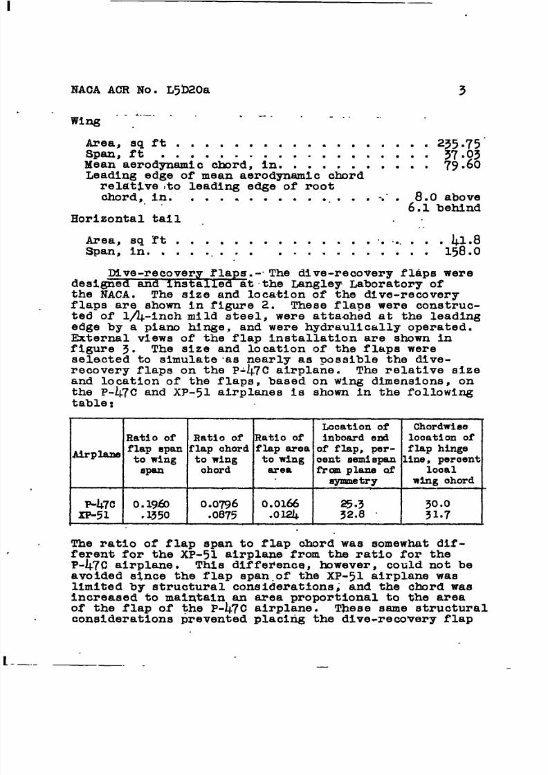
wing “ -.
. -. . . . .
Area, si ft . . . . . . . . . . . . . . . . . ~ 237.g;”span, ftMean aerodfi&~c”c&d; ~nl 1 ~ 1 1 I 1 1 1 1 . 79160Leading edge of mean aerodynamic chordrelat~ve rto leading edge of’rootchord, ln. . . . . . . . . . ... . . -.”. 8.Oabove. .
6.1 behindHorizontal tail .
..
Area, sql’t . . . . . . . . . . . . . . .. .. . .41..8
Spare,in. . . . ... . . . . . . . . . . . . . 158.0
Dive-recovery f’laps.-The dive-recovery flaps weredesigned and ihstalled at the Langley Laboratory ofthe NACA. The size and location of the dive-recoveryflaps are shown In f’igurez. These flaps were construc-ted of’l~-inch mild steel, were attaahed at the leadingedge by a piano hinge, and were hydraulically operated.Wternal views of the flap installation are shown infigure 3. The size and location of the flaps wereselected to simulate“asnearly as possible the dive-
recovery flaps on the P-47C airplane. The relative sizeand location of the flaps, based on wing dimensions, onthe P-4.7Cand XP-51 airplanes is shown in the followingtable:
Ratioof Ratioof Ratioofflapspanflapchordflaparea
~rp- towing towing towingspan ohord area
P-47C
I
o.19&l
I0.0796
I
0.0166XP-51 q1350 .08’75 .Ola+
, 1 I
---L
ocationof Chordwiseinbosrdend looationofof flap,per- flaphingeoentaemispanline,peroentfrcnlllaneof 100al
W*Y wingohord
The ratio of flap span to flap chord was somewhat dif-ferent for the XP-51 airplane from the ratio for theP-47C airplane. This difference, however, could not beavoided since the flap span.of the XP-51 airplane wasllmited by structural considerations; and the chord wasincreased to maintain an area monortlonal to the areaof the flap of
considerations
—. .
the P-47C alrpl~nel ~ese same structural
prevented placing the dive-recovery flap
—

8/9/2019 NACA P-51X Dive Flap Mods
http://slidepdf.com/reader/full/naca-p-51x-dive-flap-mods 5/37
.I
4 NACA ACR No. L5D20a
as far Inboard as the dive-recovery flap on the P-47C air-plane. An attempt was made, however, to have as much of’the flap as possible in front of the horizontal tail,since wind-tunnel tests have shown that a part of theeffectiveness of the flaps Is due to a change In downwashat the tall. An initial dive-recovery flap deflectionof 300 was used~ because experience has shown that greaterdeflections would cause serious buffeting.
Instrument&.- In the tests of the dive-recovery flapson the XP->1 airplane, standard NACA recording instru-
ments, synchronized by means of a timer, were used toobtain the following quantities:
IndZcated airspeedNormal and longitudinal accelerationAltitudeElevator posittonDive-recovery-flap positionElevator and aileron stick forcesPitching angular velocltyPressure variation at orifice on upper surface of
stabilizer (see fig. 2)
Temperature of the free air was obtained from an indi-cating resistance thermometer corrected for adiabaticrise.
SYMBOLS
An. incremental normal acceleration, g units
AFe elevator stick-force increment, pounds
x longitudinal position of center of gravity, per-cent mean aerodynamic chord i
Ax percent change In center-of-gravity position fromselected value
dFe/th stick force per g, pounds per g
af dive-recovery-flap deflection, degrees
P standard air density, s l ugs per cubic foot
.“

8/9/2019 NACA P-51X Dive Flap Mods
http://slidepdf.com/reader/full/naca-p-51x-dive-flap-mods 6/37
—. —
NACA AOR No. L5D20+ . 5
a velocfty of -sound,feet per seoond
w -~@08a we-ight.of .-alrplang~,ounds. . . ... ...-..-J
rd. Mach number
Be elevator derlectiori,degrees
TESTS, RESULTS, AND DIS~SSION
The c&racteristlcs of the dive-reoovery flaps on .the XP-51 airplane were investigated at Mach n~bers
ranging from o.~ to 0.76. The’airplane was trimmed forzero stick force In gliding flight at a given speed andthen the dive-recovery flaps were deflected. Records
were taken of the dd.ve-reoovery-flapdeflection and theensuing maneuver. The pilot was instructed to simulatethe stiok-free condltlop during the maneuver qnd to uaecontrol only to prevent excessive accelerations. Thetest runs were all,made at a pressure altitude of approxi-mately 20,000 feet.
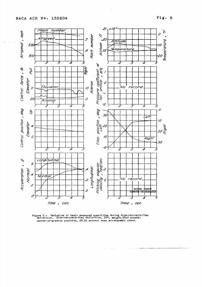
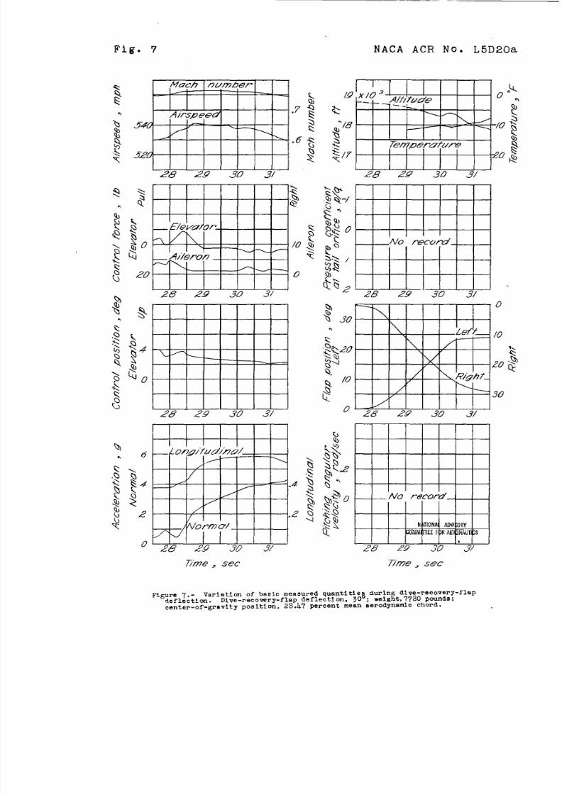
Time histories of use of’ the dive-recovery flaps
with the Initial dive-recovery-flap deflection of 30°are shown In figures 4 to 10. These figures show thatthe increase in normal acceleration due to use of thedive-recovery flaps Is smooth and slmllar to that whloha pilot would effect in a dive pull-out. It may benoted that even though in several of these maneuversthe dive-recovery flaps did not deflect equally, the.pilot reported no appreciable rolling, which indicatesthat some differential-flap action can be tolerated.The time histories of pressure coef’ficlent p/q at anorifice on the upper surface of the horizontal tail(fig. 2) were uqed to detetine whether any tail buf-
feting occurred during use of the dive-r6covery flaps.”The data confirmed the pilot~s opinion that no buffetingoocurred. The size and length of tubing connecting theorifice to the recording pressure cell was such thatoscillations of about”25 cycles per second or.less couldeasily be recorded.
From the data given .infigures 4 to 10, the ohangeIn normal acceleration An due to use of the dive-recovery flaps at various Maoh numbers was determined.
.
—— — .—-
8/9/2019 NACA P-51X Dive Flap Mods
http://slidepdf.com/reader/full/naca-p-51x-dive-flap-mods 7/37
— . .
6 NACA ACR No.-.5D20a
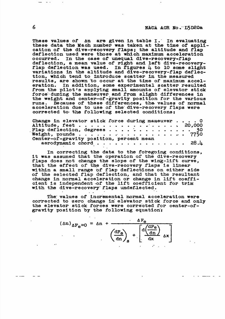
These values of An are given In table I.” In evaluatingthese data the Mach nwnber was taken at the time of appli-
cation of the dive-recovery flaps; the altitude and flapdeflection used were those at which maximum accelerationoccurred. In the case of unequal dive-recovery-flapdeflection, a mean value of right and left dive-recovery-flap deflection was used. In figures 4 to 10 some slightvariations in the altitude and dive-recovery-flap deflec-tion, which tend to introduce scatter in the measuredresults, are shown “tooccur at the time of maximum accel-eration. In addition, some expertiental scatter resultedfrom the pilotts applying small amounts of elevator stickforce..duningthe maneuver.and from slight differences in
the wetght and center-of-gravity position for the variousrune. Because of’these differences, ths values of’normalacceleration due to use of the”dive-recovery flaps wereoorrected to.the following selected conditions:
Change in elevator stick force during maneuver . . . . 0Altitude, feet . . q . . . q . . . . e“. # . . b 20,000.Flap deflection, degrees . . . . ‘.. . . . . . . . . 30Weight, pounds . . . . . . ti. . . . . . . . . .. . 7750Center-of-gravity position, percent mean
aerodynamic chord. . . . . . . . . . . . . . . 28.4
..In correcting the data to the foregoing conditions,it was assumed that the operation of the dive-recoveryflaps does not change the slope of the wing-lift curve,that the effect of the dive-recovery flaps is linearwithin a small range bf flap deflections on either sideof the selected flap deflection, and that the resultantchange in normal acceleration or change in lift coeffi-cient Is independent -of the lift coefficient for trimwith the dive-recovery”flaps undef.lected...
..
The:values of incremental normal acceleration werecorrected to “zerochange in.ele”vatorstick force and onlythe elevator stick forces were corrected for center-of-gravity position by the following equation”:
(An)*Fe=O = An +AFe
(%9s +!!?,.] .. .
.“. .

8/9/2019 NACA P-51X Dive Flap Mods
http://slidepdf.com/reader/full/naca-p-51x-dive-flap-mods 8/37
—.1
.,
NACA ACR No. L5D20a 7
where subscript s denotes the selected conditions pre-vl’ouslyspecified. The value of An was not corrected
for.p-e t~ Genter-of=gratity.ozai,tlonecause theeffeot of this variable had not been determined fromflight tests. It is thought, however, that such a Corrrect ion would have q larger effect on the measured results
4-)
dl?e
‘xthan the correction obtained from ~ Ax.
The values of dFe/ti” and the rate of change
of dFe/ti with center-of-gravity position were deter-
mined from the fllght tests as 8.5 and 1.2, respectively,
for the selected center-of-gravityposition. In deter-mining 4Fe, stick-force increments of less than 1 poundwere ignored since such values would be within the accu-racy-of the control-force recorder. The increment AFe
was determined as any change In applied stick force thatwould contribute to a change In the acceleration resultingfrom deflection of the dive-recovery flaps. The valuesof AFe and Ax used are given In table I. Values ofIncremental normal acceleration corrected for stick-forcechange and center-of-gravityposition are also given in
table I.
The values of Incremental acceleration An werecorrected to the selected altitude, flap deflection, andwei”ghtby the following equation:
.
AnB = (An),,eo(-)(%)(t)
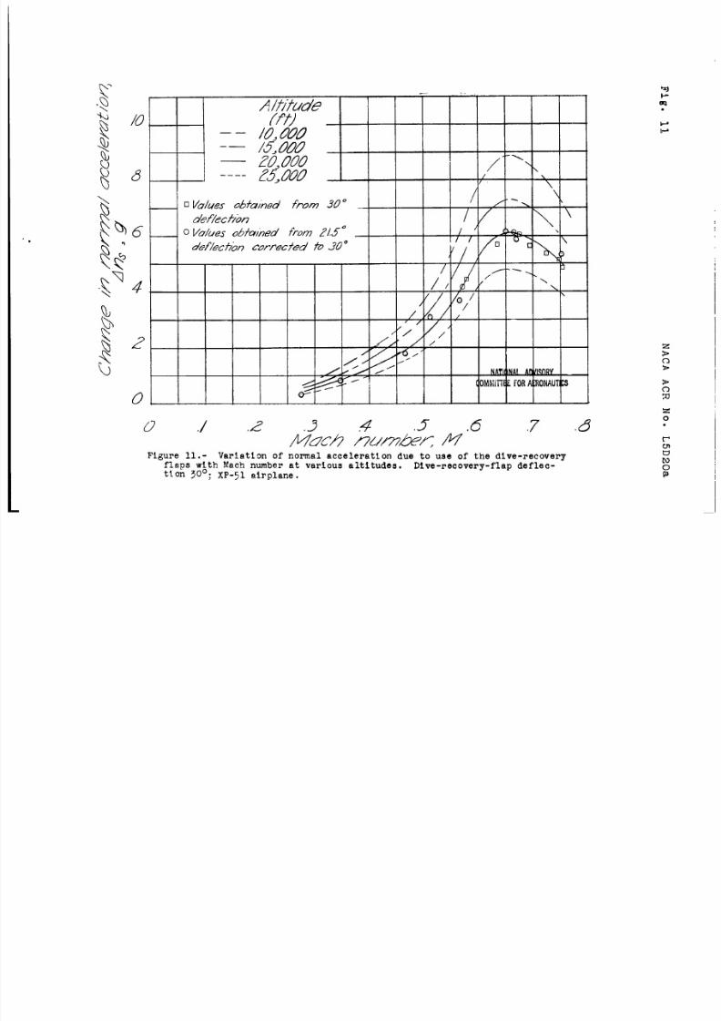
values of Ana are given in table I. These values qre
shown plotted against Mach number in f’igura11. 0urve8are also given in figure 11, which show the -effectofthe dive-recovery flaps at altitudes ranging from 10,000to 25,000 feet, These curves were derived by the fol~lowing equatlon~
(Pa)2a1t
An20,000 ft (Pa2)20;OOO.ft . .
—..

8/9/2019 NACA P-51X Dive Flap Mods
http://slidepdf.com/reader/full/naca-p-51x-dive-flap-mods 9/37
..-, .-. ..-, —
8“ .,) l’JAC@kQEt,l@,.I15~@
In.calculating .tllpe.f’fwtQf the dive.-recoveryflapa ataltitudes other than .2QJ)bU’eet, the-same a.ssumptlon
was made as In cqrrectlng tliedata to the.selected alti-tude - that 1s, “therequlta t change In normal accelera-tion Is independent of the rift coefficient required to
-. trim .t.heirplane”with thq dive-recovery flaps unde.fleeted..A”scan be seen In figure 11.,dfve-recovery flaps deflected300 can cause acceleration increments at the lower alti..tudes in excess of the.design load factor of the airplane.When thig possibility became evident, the dive-recovery-flap deflection was reduced to 21.5° and tests wererepeated. ,:.
. : . .. :
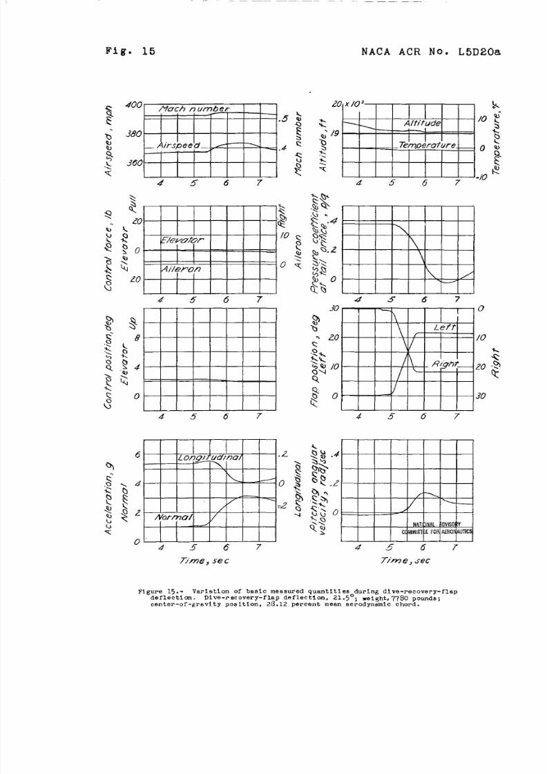
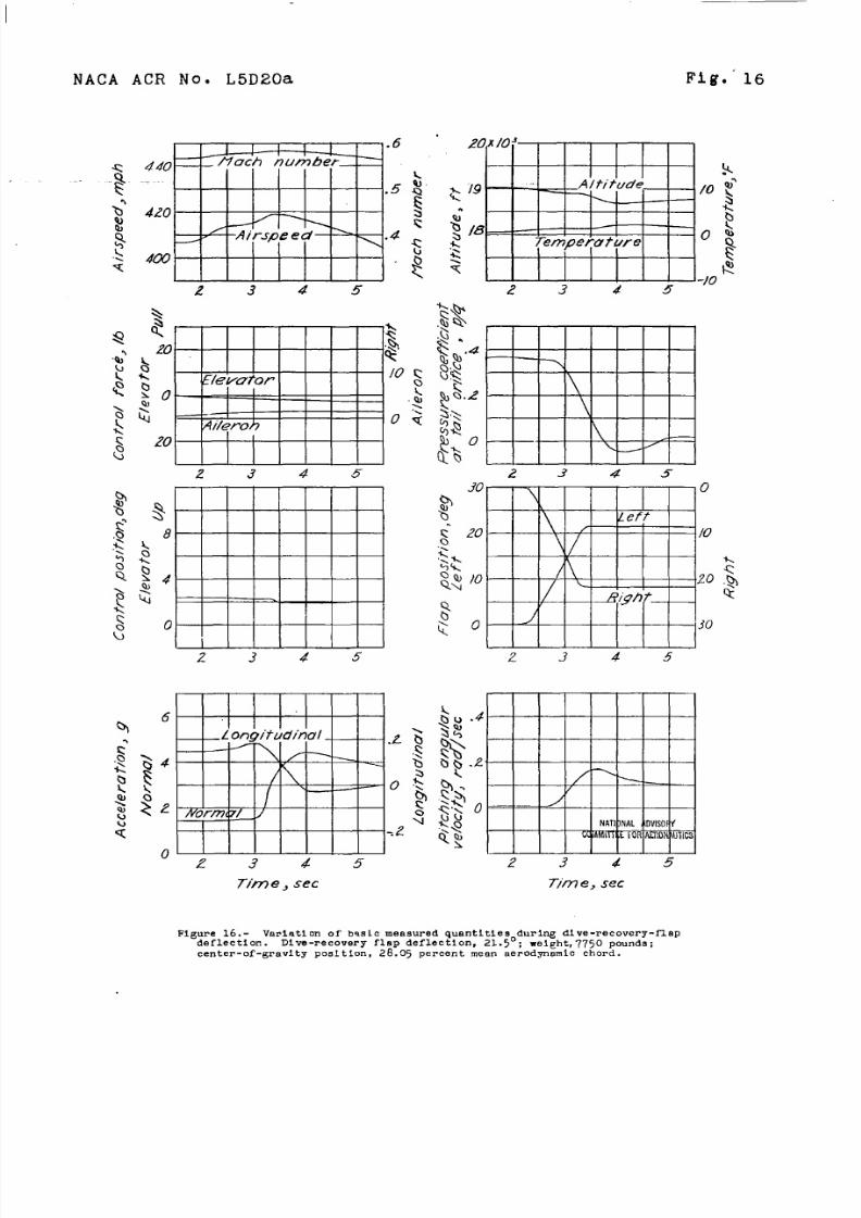
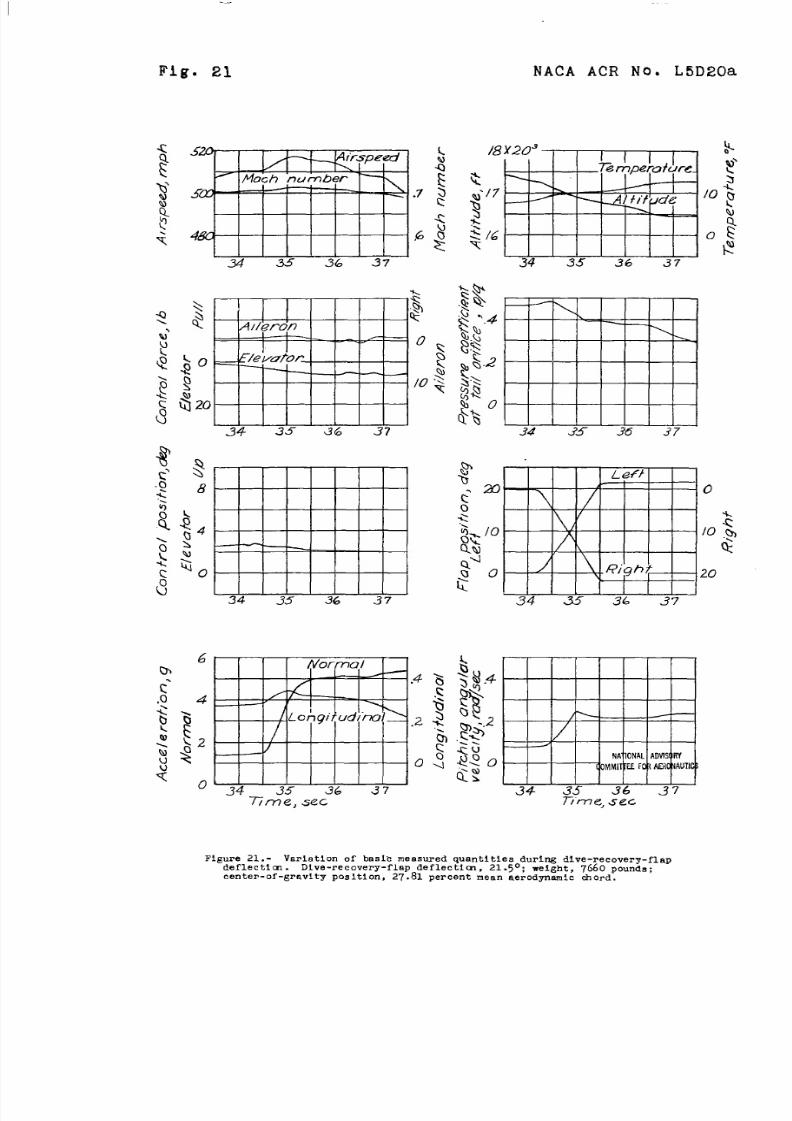
jFi&@is 12 to 21 are ’timehistories of the.t~st runs.... -. rn.a@with the dive-recovery flaps deflected 21.5°. Thecha~e In”normal accelerate.m with”Mach nw.ber was deter-.. . ..1 mined and the values of incremental acceleration were
-.... ..-.corrected.t.o..theelected conditions In the same Way asfor the tests of the dive-recovery flaps deflected 30°.
1...... The.varlationof’change in normal acceleration due to.... ...+.“.defilectfnghe dive-recovery flaps 21.5° with Mach number.. ..2s shown in figure 22. The curve shown for the variation
Qf:.~O~al.aCCeleratiOri. with Mach number at an altitude ..,. of 120,000feet was obtained from the corrected test
results and the curves for other altitudes were ‘calculatedon.ths basis of these results. Figure 22 shows that thedive-recovery flaps set at 21.5° will produce an adequate
..stlcJc-freedive recovery at all practical altitudes withinthe.Mach number range tested without exceeding the llqit:.load factor of the airplane.
Figures 11 and 22 show that the maximum effectivenessof the.dive-recovery flap when deflected occms at a Machnumber qf approximately 0.65 with a decrease In effec-tiveness as the Mach number is Increased. Also, no con-
sistent trend is apparent when test values of eitherflap-deflection setti~ are corrected to 21.5° or t0300;., therefore the effect of the flaps can be considered td
be linear between these two angles.,.
. .. Tests to”terminal Mach number of the airplane.,whichIS estimated to be 0.82, have not been made using thedive-recovery flaps. The present data, however, indicatedthat the dive-recovery flaps would @ an emergency effecta satlsfactb$y dive recovery at the estimated terminalMach number.of the XP-51 airplane.
.

8/9/2019 NACA P-51X Dive Flap Mods
http://slidepdf.com/reader/full/naca-p-51x-dive-flap-mods 10/37
— —.. -
NAGA AOR.NO. L5D20a 9
.
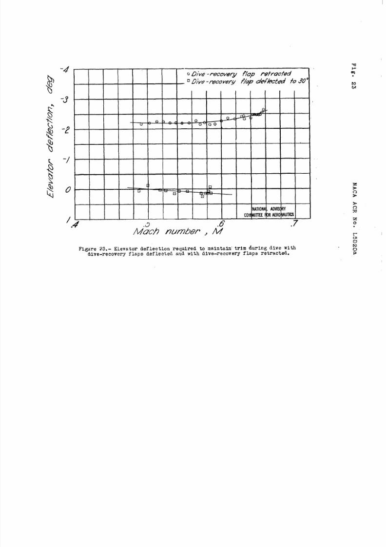
me elevator defleot$o.nsthat wotid cau s e a changeIn longitudinal trim equivalent to that c&used by
deflecting the dive-recovery flEps were determined by
flylng with the gaps.,qd.efle.cted and vflth the flaps...,,“defleoted 30°. The data obtained are given In figure 23,whfoh shows that defl.eoting’the dive-recovery flaps 30°,in tiheB@oh number range tested, wmild re$miltIn a normalacoelenation corresponding to that obtained with approxl-nmtely 2° change in elevator deflection. At very hl&Mach numbers, however, the elevators may beoome relativelyless ef’feotivein produoing a ohange in normal aooelera-tlon. . .
Wind-tunnel tests have shown that the change inlongitudinal trim provided by the dive-reoovery flapsat hi
PMaoh numbers is caused by a ohange In pitohing
momen of the wing am.by a change’in “anglaof attackof the tall. The ef.feCtof ohange in pttchlng moment ofthe wing is rather small oompared with the effect of theohange in angle of attaok at the tall when the dlve-reoovery flaps are plaoed at about one-third of the wing
chord behind the leadlng edge. If the flaps are Installedfarther back on the wlng,the wing pitching moment beoomesnegative and is of such magnitude as to onuse an appreciablereduction In the effect of the dive-recovery flaps. metwo factors that contribute to the ancle-of-attaok ohange
at the tail are: (1) a decrease in an@e of attaok tomaintain the some lift (chanae In the arucleof zero lift),and (2) a change in dowr&ash-at the tail-due to a cha~e -in spanwise loading on the wing, The cha~e in downwashat the tall due to the altered spanwise loading can beseen to be greatest *en the dive-reoovery flaps aredirectly ahead of the tail,
Available data Indicated th~.tseleotlon of satis-factory dive-recovery flaps for any conventional airplaneIs possilile. The flaps should.be located approximately
one-thtrd of the wing chord behind the Ieadlng edge andshotid be ahead of the horizontal teil. The selection ofdimensions of the dive-recovery flaps shotid be based onwing dimensions as in the present case. -somewhats~llerdtve-recovery flaps could probably be tolerated If thedive-reoovery-flapdeflection wore increased. The rate
of dive-recovery-flap deflection should bo similar tothat used in the present tests since lower rates mightresult In a slower recovery with a resultant greater lossof altitude in recovery even though the same value of
\,
. .
..
—.— ——- . - .—

8/9/2019 NACA P-51X Dive Flap Mods
http://slidepdf.com/reader/full/naca-p-51x-dive-flap-mods 11/37
10 ‘ “ NA’CAACR No.”L5U20a
. .
maximum .acoeleratilmwould fintilly”bereached. Flighttestsj as’in.the present in”veatigation,wiil probably benecessary *O obtain the final fJap”configuration, but a
step-by-step test prpgram similar to the one describedherein can be.-conducted with a mlntium amount of danger .involved. ..“.
CONCLUSIONS
From results of flight tests to determine the effec-tiveness of dive-recovery flaps as installed on the NorthAmerican XP-51 airplane the following conclusions were
drawn: .. . . .
1. The dive-rec&very f’~apso,nthe XP-51 airplaneprovided a smooth dive recoveuy at.high speeds with littlelag between deflection of the f’lapsand the resultant .“.acceleration. . .
2. The effectiveness of the dive-recovery flapsvaried linearly with deflection.within the deflectionrange tested.
3. The effectIveness of the dive-recovery fla szncreased with an increase In Mach number Lp to O. 5 andthen gradually decreased with further increase in Machnumber.
,.
.4. No buffeting resulted from the use of the dive-recovery flaps at any speed tested and no rolling of theairplane was encountered during tests when the flapswere deflected unequally.
5. The data indicate that the dive-recover flapszused on the XP-51 airplane, when deflected 21.5 , will
probably effect satisfactory dive recovery up to theestimated termtnal Mach number for the airplane withoutexceeding the design load factor anmrhere jn thespe~d Results calculated.from dtitaobtainedin test~a%& a 30° flap deflection indicated that.the
8/9/2019 NACA P-51X Dive Flap Mods
http://slidepdf.com/reader/full/naca-p-51x-dive-flap-mods 12/37
. .
I!MA AUR No. “L5D20a
design load faotor mayaltitudes below 15,000
... .......... -.. ..
11
be exoeeded at high speed atfeet.
, - ----- .- .-
Langley Memorial Aeronautical LaboratoryNational Advisory Committee for Aeronautics
Lqgley Field, Va.
REFERENCE
1. Hood, Manley J., and Allen, H. Julian: The Problemof Longitudinal StabilltSpeeds. NACA CB ~~0.3K1~,~~~~’rol at High

8/9/2019 NACA P-51X Dive Flap Mods
http://slidepdf.com/reader/full/naca-p-51x-dive-flap-mods 13/37
ITA~LE 1,. SUMMARY OF Pb~TINENT MEASURED AND CORRECTED
OBTAINED DURING DIVE-RECOVERY-FLAP DEFLECTION
.
DATA
.—)
dnAn~ Ans,
Axcorrected
for zero stick(An corrected {An corrected ~
Figure An dFe ‘~e~c~n~ ../force and to a ! ~’~~i~~~~c~~~ 1 $&;:;:’;;:
, (g) (lb) ‘-”” selected center- iweight and a weight, and a I
Iof-gravity
flap deflection , ~.lap deflectionposition
of’ jof~)–____L ______
Of 21.50).—. ——.- ..—
Dive-recovery-flap Ueflectionj~~o
J
r
~ - ~.60 2.50 ~.~ ——r—— Loy~ ‘—----- ~:;~~—
~ ~.~ ;.::I 4.0
-.23?t
k
;“; t
3.8-.15 i .86
7t:75 I 6:50 -.o~ ~:52 1
?4.12 k:17
8 .35! 2.00 . o~” I ~ yl.
u
~: ‘5.8 ~.oo .35 ~:?: ! ;;
6.15 3.500.15
.67 ~ 6.56 ~ 6.03 i J&_._—~ –.—
Dive-recovery-flap deflections 21.50—.——
‘—12 o.2b~----- 0.04 -~
—..
0.24 I O:;$;
;~ ~::~~:;::j!
o.2~
.12 i .60 Ii .59.~o j 1.29 ~*77 1.26
.28 i 2.23‘ ;:~; \ ::(); ‘ .5 i
.11 2.2216
t
3.19 .19 3.001~ . . .’3 2.80 3.69 2.64
18 t:k5 ;:;;.12 b.57 6.11
1
19
20 4.55 1.00.28
q34.77 6.184.66 I
~:g5.84
21 3.95! 5.00q 59 4.49 ! 5.37 3:8)+

8/9/2019 NACA P-51X Dive Flap Mods
http://slidepdf.com/reader/full/naca-p-51x-dive-flap-mods 14/37
!23c)>
zo.
Figure l,- Three-quarter front view of the XP-51 airplane. Gal.

8/9/2019 NACA P-51X Dive Flap Mods
http://slidepdf.com/reader/full/naca-p-51x-dive-flap-mods 15/37
NACA ACR No. L51’)20a Fig. 2
,.
1
0 NATIONAL ADVISORY
COMMITTEEOR AERONAUTICS
.
Figure2.- Locationof dive-recoveryflapson theXP-51airplane.
—

8/9/2019 NACA P-51X Dive Flap Mods
http://slidepdf.com/reader/full/naca-p-51x-dive-flap-mods 16/37
NACA ACR No. L5D20a Fig. 3a,b
(a) Flap deflected 30°.
[b) Flap fully retracted.
Figure 3.- Dive-recovery flap located on left wingof the xP-51 airplane,

8/9/2019 NACA P-51X Dive Flap Mods
http://slidepdf.com/reader/full/naca-p-51x-dive-flap-mods 17/37

8/9/2019 NACA P-51X Dive Flap Mods
http://slidepdf.com/reader/full/naca-p-51x-dive-flap-mods 18/37
Fig. 5
Figure 5.- Varlatlon of bnslc measured qumtlties during dive-recovery-flapdeflection. Dive-recovery-flap deflection, 30°; wei@lt,7~50 pounds:
center-of-gravity position, 28.63 percent mean aerodynamic chord.
8/9/2019 NACA P-51X Dive Flap Mods
http://slidepdf.com/reader/full/naca-p-51x-dive-flap-mods 19/37
NACA ACR No. L5D20a
2/
,
A/o r e Co r (7’
c o1
/2
77AW , sec fime , sec
Figure 6.- Varlntlon of basic measured quantities during dive-recovery-flapdeflection. Dive-recovery-flap deflection, 300; weight, ~810 pounds;
center-of-gravity poaltion, 28.55percent mean aerodynamic chord.
8/9/2019 NACA P-51X Dive Flap Mods
http://slidepdf.com/reader/full/naca-p-51x-dive-flap-mods 20/37
Fig. 7 NACA ACR No. L5D20a
7Zm e, sec 77rne , sec
Figure 7.- Varlntlon of basic measured quantltfe~ during dive-TecOverY-flaPdeflectlcm. Dive-recovery-flap deflection, 30 ; weight, 7730 pounds;
center-of-gravity pOslti On. .z’9.J47ercent mean BerOdP~lc ch’xd”

8/9/2019 NACA P-51X Dive Flap Mods
http://slidepdf.com/reader/full/naca-p-51x-dive-flap-mods 21/37
.. .. ..
NACA ACR No. L5D20a Fig. 6
?7m c, sec
— — — \
/
{
N A’ ‘ ! J N 4 L AD VI S R Y
c o ma T I r E E - F o r r rK m s
1
/ 2 4577me{ sec
Figure 8.- Varlatlon of basic measured quantities during dive-recovery-flapdeflection. Dive-recovery-flap deflectl On, 30°; weight, 7870 pounds;
center- of-grnvlty posltlon, 28.36 percent mean aerodynamic chord.

8/9/2019 NACA P-51X Dive Flap Mods
http://slidepdf.com/reader/full/naca-p-51x-dive-flap-mods 22/37
Fig. 9 NACA ACR No. L5D20a.
/ ~
/ ‘/ /,2
I \.
LOf)g it u di n d
oNornw/
/
.2.
/77 fme, SCC
45
30 0
.
#’mk J ’ I I
/0c -.0
+2
“ $ %
i
wr ~ ‘ —
NAI ON A LFlovlslWLm
T ‘
/ 2 J 5Tim e, sec
\Fgure 9.- Varlatlon of basic measured quantltlea during dive-recovery-flap
deflection. Dive-recovery-flap deflection, ~OO; “eight, 7750 powds;
center-of-gravity poaltlon, 28.05 percent mean aerodynamic chord.

8/9/2019 NACA P-51X Dive Flap Mods
http://slidepdf.com/reader/full/naca-p-51x-dive-flap-mods 23/37
NACA ACR No; L5D20a Fig. 10
8
fa 6
o
Y.-... ---- .-
\
/ 2 3 4
.2.
0
2.
/ 234T i” m e, sec
/ -
\ t
/
/
/\ &
/ z 3 4
Figure 10.- Vari atlon of basic measured quantities during dive-recovery-flapd~flectlon. Dive-rec every-flap deflect ion, 30°; weight, 763opounds;center- of-~ravlty position, 27.73 percent mean aerodynamic chord.
o
/0
30
.,,,,,.,,,., ! I .! . . ii !! . . . .-, ---- .,. -,.,.--,- ,.--—-—
8/9/2019 NACA P-51X Dive Flap Mods
http://slidepdf.com/reader/full/naca-p-51x-dive-flap-mods 24/37
— . .
Altitude(xv
– – /“:$$——
Zb.uoo‘--- Z3-Jmu
/ “ “ \// \ \
k u u v u / u e s oh jajned fpom
o
300/ / --, “
H
deflechon / / \
o Va/ues obfw ied f rom 2/50 / J \
def /eC770n Cor rec +d b 300/
H .1
u c
w
NATIIWJAIAIWIWM?V
0 ./ az .3 .+ .5 .6 7 dM’ucb / z#m5eYC 27
Figure 11. - Varla t lcm of normal accelera te on due to use of the dive-recovery
flaps wfth Mach number a t var ious alt itudes. Dive-recovery-fla p de f lee-t i on 30°;Xp-slairplane
z0.
I
I

8/9/2019 NACA P-51X Dive Flap Mods
http://slidepdf.com/reader/full/naca-p-51x-dive-flap-mods 25/37
NACA ACR No. L5D20a Fig. 12
‘t
I I I I IJ
2ZC— — /Yuch ‘numbep —
.2
2 0 G#
A i rsp eed.
/80
/5 /6 /7 /8
.\
/5 /6 /7 /8
6
.2
4LOng iru di f i 0 /
oz
Normo/.2
A/5 /6 /7 /8
Time, sec
/5 /6 /7 /8
/5 /6 17 /8 “
.4
./?
o — — — — — — — -
Mww$ + h m* —COM l l E EORAER0N4UIt s
/5 /6 /7 /8
T/”m e, see,
Figure 12.- Variatlon of basic measured q“antltles during dive-recovery-flapdeflection. Dive-recovery-flep deflection, 21.5°;eight, 7E170 pounds;
center-o f-ernvlty position, 28.36 percent mean aerodynamic chord.

8/9/2019 NACA P-51X Dive Flap Mods
http://slidepdf.com/reader/full/naca-p-51x-dive-flap-mods 26/37
Fig. 13 NACA ACR No . L5D20a
280Much number
.4 $
c
260 .3 ;
~ -‘Airspee d
~
240 -t
/0- // /2 /3
/0 // /2 /3
/0 // /2 /3
7/”me , .rec
/0 // /2 /3
/0 II /2 13
/0 // /2 /3
.4 -
./?
o .
NA I I CA L _ Ay & ! x L !
/ 0 / 1 / 4 ? /3
Time, sec
Figure l~.- Varlatlcm of tnglc measured quantities durl~ dlve-recovery-
flap deflection. Dive-recovery-flap deflection, Z1.5 ; weight, 787o
pounds; center-of-gravity poaltlon, 28.28 percent mean aerodynamic chord.

8/9/2019 NACA P-51X Dive Flap Mods
http://slidepdf.com/reader/full/naca-p-51x-dive-flap-mods 27/37
NACA ACR No. L5D20a Fig. 1?
“0iT17FTnu’8 9 10 II
T ime, sec
.4
.2
\ ,0
/ ‘
‘b+-++-+”/ 0
$ ‘ttmmlsr7 8 9 /0 I f
.4
.2 !
\ \
o / yw QJULw P&
C(MMI T T E F OF A E RO ) AU T I C S
78 9 /0 I t
T ime, sec
Figure 14.- Varlatlon of basic meastxred quantities during dive-recovery-flap
deflection. Dive-recovery-flap deflectl~n, 21 .~”: weiEht , 781o pounds ;center-of-gravity posltl on, 28.20 percent mean aerodynamic ct,ord.
8/9/2019 NACA P-51X Dive Flap Mods
http://slidepdf.com/reader/full/naca-p-51x-dive-flap-mods 28/37
Fig. 15 NACA ACR No. L5D20a
400f loc h num ber
,5 k380 -g
_Air.spee d_. - — \ . .4 c<
360 8R
456 7
45 67
4 56 7 4 567
4 5 6 7
~:$”:o / v—
Q N AT I N AL i DV I S O Y
c c MMI T I : E F O R A E R o hA UT I C S
4 567
Tim e, se c Time, ~ec
Figure 15.- Var18tlon of basic measured quantities during dive-recovery-flap
deflection. Dive-recovery-flap dnflectlon, 21.5°; ~.gi ..+ t ,~~30 ~OWdS:center-of-gravity posltlon, 28.12 percent mean aerodynamic chord.
8/9/2019 NACA P-51X Dive Flap Mods
http://slidepdf.com/reader/full/naca-p-51x-dive-flap-mods 29/37
NACA ACR No. L5D20a Fig.” 16
I I i 1 ! f.61
4 40 — If luc h numbe~ —
.5
420 / ~ ,
— ‘/ —A/ rspe eo’ , .4
m
z 34 5
2 3 d 5
II[ longi tud ina l .,?
/ ‘ -
/ Y,
I- 0
Aiorn717/ J
I..2
z 345
Time= see
“
Z Ox 1 0 ’
I $
19 “’ _ A I t i t uo ’e / 0 ‘f
I ~
— —h
/ 8:?empetytye
tiiiiliilEt?!
23 4 5-10
\
\
\ . H
2 3 4 530
\ ,0
Lef fr20
\,/
/0
/\
+-.
)0 -20 &
/%Ight ‘%/
o J 30
2 3 4 5
.4
.2,
/ ‘ ~ ./
o1
N AT I I NA L j I D VI S OF
c c m m A E R ONWmcs
2 3 4 5
Tim e, sec
Figure 16.- Varlntlon of bqsic measured quantltlesodurlng dive-recovery-flapdeflectlcm. Dive-recovery flmp deflection, .ZL.5 ; welght,7750 pounds;
center-of-gravity posltlon, .Z8.C15percent mean aerodynamic chord.
8/9/2019 NACA P-51X Dive Flap Mods
http://slidepdf.com/reader/full/naca-p-51x-dive-flap-mods 30/37
Fig. 17
I
NACA ACR No. L5D20a
440I
t iuc h kUmbek- .6
k
4201.5 >
_ A ir s p ee d Q
\ <400 ~ 8
t
/ z 3 4
/ 234
I I I
‘12!zXm
2
k
o rma
. Z
n“
/ z 3 4
Time, sec
2 0 4 / 0 3
~
/9 Al t i~u de. _ ~n
/0 s
/8g
Tempe ru rure
0 $1?
/ 2 3 4
/ z 3 4
/234
.4
.2
0 -
NATNAL DV I S OYC (MMI EF OAEROhUT I CS
/ z 3 4
Time, sec
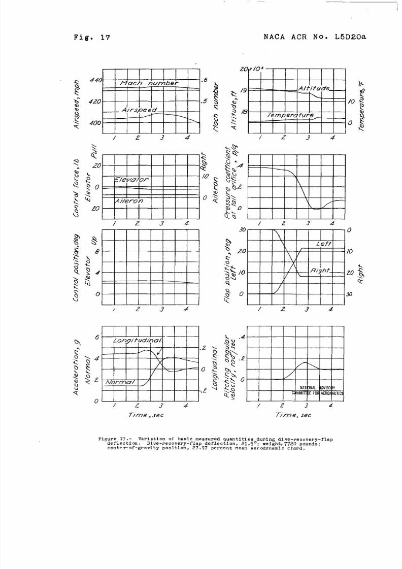
Figure 17.- Varlation of basic mea.nn.ed quantltlesodurlng dive-recovery-flap
defleet Im. Dive-recovery-f’lap deflection, 21.5 ; wefght,7720 pounds;
cente~~f-~ravlty posltlon, 27.97 ?ercent mean aercdynam!c chord.
8/9/2019 NACA P-51X Dive Flap Mods
http://slidepdf.com/reader/full/naca-p-51x-dive-flap-mods 31/37
NACA ACR No. L5D20a
1o&?udW_
MOr fn u /—
72
/ 34Dmze , 5(?C
Fig. 18
\
\
- / —
/234
/ — --i= – [y
// ’
HA T I OLAL l s o
/23 477m e. sec
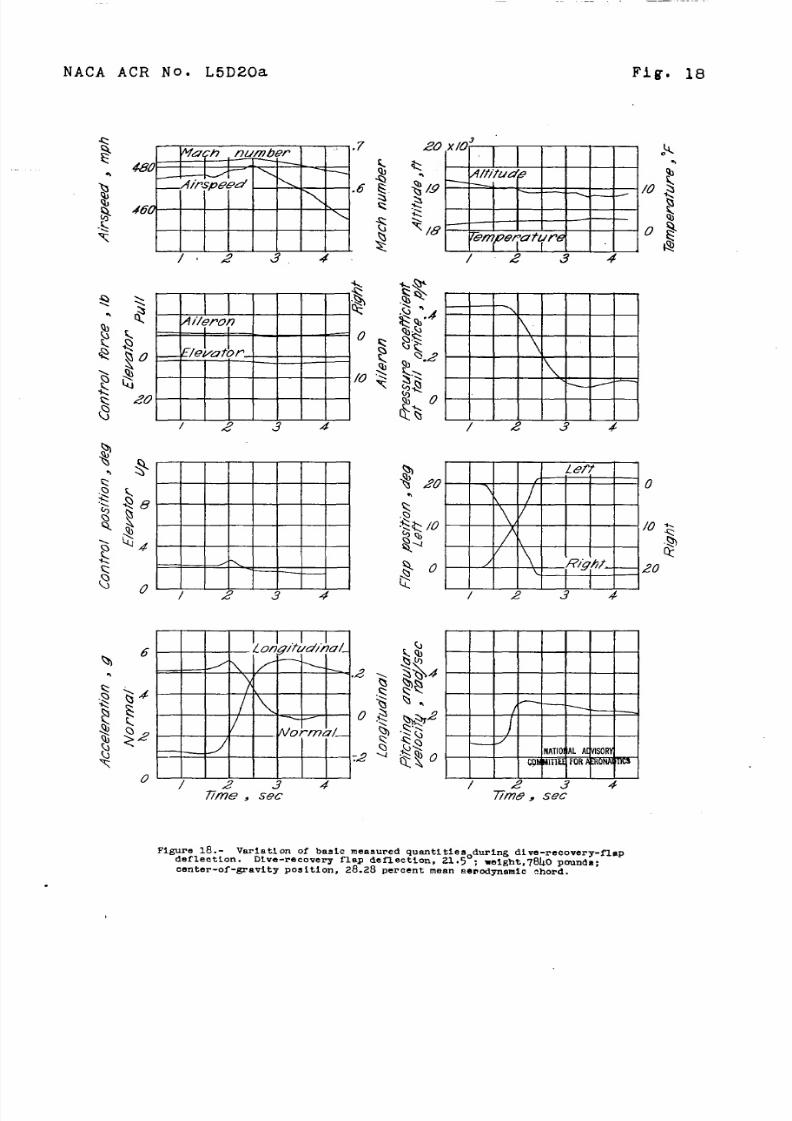
Figure 18. - Varlatl on of basic measured quantl tlesodurlng dive-recovery-flapdeflection. Dive-recovery flap deflection, 21.5 ; melght,7t340 pmnds:center-of -gravity POS ltion, 28.28 percent mean senodynamlc ?hord.
8/9/2019 NACA P-51X Dive Flap Mods
http://slidepdf.com/reader/full/naca-p-51x-dive-flap-mods 32/37
Fig. 19 NACA ACR No. L5D20a
I I
6Norrra I
/ \/
4 “
A , /
, .2/)<
2 ,.“\ 0
Longi fud lro l .
0 / 2 3 4 3-Tlrne)sgc
/o ‘ “
I/NA TNA L OV I SOY
e tMf l l t i 3H 3 $ k E R e t
/ z 45Time?sec
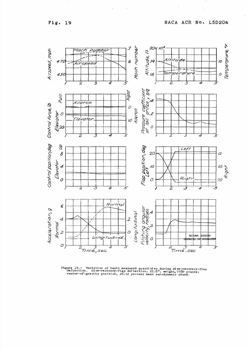
Figure 19.- Vnrl.stion of basic measured quantities during dive-recovery-flapdeflection . Dive-recovery-flap defle~tl On, .21,jo ; “ e~g~t, 77&3 ~omd~ ;
center-of-gravity position, 28.12 percent mean aerodynamic chord .
8/9/2019 NACA P-51X Dive Flap Mods
http://slidepdf.com/reader/full/naca-p-51x-dive-flap-mods 33/37
NACA ACR No. L5D20a Fig. 20
X203 Ternperpf f f re . ‘o. 1
\
\o
I2 3 4 5
\
\
\ _ L .
2 3 4 5
6 . #o!mL 1. _ <U~ S?V/ - < — ~
.2 $ 3?.4( \
4/ Y . R -Q<
J
-
r/ %? ‘ 2b . ~ . , /2
/{ c
Q <: — -- -
.2-4 * LO NATNALwl s o t Y
& su MMI T I z F o w m
o ~ ~4 ~ 23 s77m e, s ec T I’m e, a 4e.z
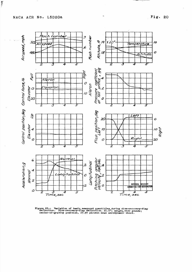
Hgure 2 0 . - Vcriatlon of baaic measured quantttiea durhg dLve-recovery-flapdeflection. Dive-recovery-flap deflection. 21.5°; velght,7720 pounds;
CCUItCr-Of-~8tit~ p08itf0n, 27.97 percent ineen aeroclyn~ic chord.
o
/0;
i?w
8/9/2019 NACA P-51X Dive Flap Mods
http://slidepdf.com/reader/full/naca-p-51x-dive-flap-mods 34/37
....
Fig. 21
520
‘ )-loc h ‘number -‘5C0 L .7
48a ,6
34 M 36 37
6Cn
.
$A i l.w o n
1 r— o
E/evu~of
—— . .
/0
34 35 J6 37
— .
34 35 36 37
Norpal/ —
/’h
/ Lc l+9 i l ud I ’m 15
/
,34 35 36 37
7ime, .se~
NACA ACR No. L5D20a
* V7
Wttmttl4 35 36 37
.
34 35 36 37
L &f/I .
4-
/
/
\
A
I
34 35 36 37
/ ~
/w ‘ I ONA LOV I S f
( I MMI TF OARoWJ T I C
34 35 36 37T /”me , sec
Figure 21. - Varlatlon of basle measured quantities during dive-recovery-flapdeflectlm. Dive-recovery-flap deflectim, 21.5°: weight, 7660 pounds;CenteP-Of-gravity pOsltl On, 27.81 percent mean aerodynamic chord.

8/9/2019 NACA P-51X Dive Flap Mods
http://slidepdf.com/reader/full/naca-p-51x-dive-flap-mods 35/37
Figure 22. - Variation of normalaccelerationuetouseofthedive-recoveryflapa with Mach number at varloua altltudea. Dive-recovery-flap deflec-tion 21.50; XP-51 airplane.
zo.
8/9/2019 NACA P-51X Dive Flap Mods
http://slidepdf.com/reader/full/naca-p-51x-dive-flap-mods 36/37
-4
-3
-2
-/
G’
/
Q Dive -recovery flop re t ruc t id
DDive -recover ’ f/up U&ktd t o 300
L]
u m--u-Fl
El~ b
NATKIN. AWN(w
co!AWTEEFM ml oWll?cs
‘ .4 .6’AX& mwnbef , M
./
Figure 23, - Elevatordeflectionrequired to malntaln’trim dur ing dive withdive-recovery flapg deflected and with dive-recovery flaps retracted.
Nw
zo.
rWI
U

8/9/2019 NACA P-51X Dive Flap Mods
http://slidepdf.com/reader/full/naca-p-51x-dive-flap-mods 37/37
.,,. .. . .. . -.G ~ - ... .
..
—..
lllllllllllMl]lfllnl3 1176013544300
Related Documents