NA-series HMI Programmable Terminal E3NW-ECT Window to Set up and Monitor EtherCAT Communication Unit for Sensor Amplifiers NA5-15[]101[] NA5-12[]101[] NA5-9[]001[] NA5-7[]001[] V416-E1-01

Welcome message from author
This document is posted to help you gain knowledge. Please leave a comment to let me know what you think about it! Share it to your friends and learn new things together.
Transcript

NA-series HMI Programmable Terminal
E3NW-ECT Window to Set up and Monitor EtherCAT Communication Unit for Sensor Amplifiers
NA5-15[]101[] NA5-12[]101[] NA5-9[]001[] NA5-7[]001[]
V416-E1-01

2
■ IntroductionThis guide provides reference information for the use of the E3NW-ECT Window to set up and monitor the EtherCAT Communication Unit for Sensor Amplifiers in NA-series HMIs. It does not provide safety information.
Be sure to obtain the NA-series Programmable Terminal User's Manuals, read and understand the safety points and other information required for use, and test sufficiently before actually using the equipment.

3
Terms and Conditions Agreement
Warranty, Limitations of Liability
Warranties
Exclusive Warranty
Omron’s exclusive warranty is that the Products will be free from defects in materials and
workmanship for a period of twelve months from the date of sale by Omron (or such other period
expressed in writing by Omron). Omron disclaims all other warranties, express or implied.
Limitations
OMRON MAKES NO WARRANTY OR REPRESENTATION, EXPRESS OR IMPLIED,
ABOUT NON-INFRINGEMENT, MERCHANTABILITY OR FITNESS FOR A PARTICULAR
PURPOSE OF THE PRODUCTS. BUYER ACKNOWLEDGES THAT IT ALONE HAS
DETERMINED THAT THE PRODUCTS WILL SUITABLY MEET THE REQUIREMENTS OF
THEIR INTENDED USE.
Omron further disclaims all warranties and responsibility of any type for claims or expenses
based on infringement by the Products or otherwise of any intellectual property right.
Buyer Remedy
Omron’s sole obligation hereunder shall be, at Omron’s election, to (i) replace (in the form
originally shipped with Buyer responsible for labor charges for removal or replacement
thereof) the non-complying Product, (ii) repair the non-complying Product, or (iii) repay or
credit Buyer an amount equal to the purchase price of the non-complying Product; provided
that in no event shall Omron be responsible for warranty, repair, indemnity or any other
claims or expenses regarding the Products unless Omron’s analysis confirms that the
Products were properly handled, stored, installed and maintained and not subject to
contamination, abuse, misuse or inappropriate modification. Return of any Products by
Buyer must be approved in writing by Omron before shipment. Omron Companies shall not
be liable for the suitability or unsuitability or the results from the use of Products in
combination with any electrical or electronic components, circuits, system assemblies or any
other materials or substances or environments. Any advice, recommendations or
information given orally or in writing, are not to be construed as an amendment or addition to
the above warranty.
See http://www.omron.com/global/ or contact your Omron representative for published
information.
Limitation on Liability; Etc
OMRON COMPANIES SHALL NOT BE LIABLE FOR SPECIAL, INDIRECT, INCIDENTAL,
OR CONSEQUENTIAL DAMAGES, LOSS OF PROFITS OR PRODUCTION OR
COMMERCIAL LOSS IN ANY WAY CONNECTED WITH THE PRODUCTS, WHETHER
SUCH CLAIM IS BASED IN CONTRACT, WARRANTY, NEGLIGENCE OR STRICT
LIABILITY.
Further, in no event shall liability of Omron Companies exceed the individual price of the
Product on which liability is asserted.

4
Application Considerations
Suitability of Use
Omron Companies shall not be responsible for conformity with any standards, codes or
regulations which apply to the combination of the Product in the Buyer’s application or use
of the Product. At Buyer’s request, Omron will provide applicable third party certification
documents identifying ratings and limitations of use which apply to the Product. This
information by itself is not sufficient for a complete determination of the suitability of the
Product in combination with the end product, machine, system, or other application or use.
Buyer shall be solely responsible for determining appropriateness of the particular Product
with respect to Buyer’s application, product or system. Buyer shall take application
responsibility in all cases.
NEVER USE THE PRODUCT FOR AN APPLICATION INVOLVING SERIOUS RISK TO
LIFE OR PROPERTY WITHOUT ENSURING THAT THE SYSTEM AS A WHOLE HAS
BEEN DESIGNED TO ADDRESS THE RISKS, AND THAT THE OMRON PRODUCT(S) IS
PROPERLY RATED AND INSTALLED FOR THE INTENDED USE WITHIN THE OVERALL
EQUIPMENT OR SYSTEM.
Programmable Products
Omron Companies shall not be responsible for the user’s programming of a programmable
Product, or any consequence thereof.
Disclaimers
Performance Data
Data presented in Omron Company websites, catalogs and other materials is provided as a
guide for the user in determining suitability and does not constitute a warranty. It may
represent the result of Omron’s test conditions, and the user must correlate it to actual
application requirements. Actual performance is subject to the Omron’s Warranty and
Limitations of Liability.
Change in Specifications
Product specifications and accessories may be changed at any time based on
improvements and other reasons. It is our practice to change part numbers when published
ratings or features are changed, or when significant construction changes are made.
However, some specifications of the Product may be changed without any notice. When in
doubt, special part numbers may be assigned to fix or establish key specifications for your
application. Please consult with your Omron’s representative at any time to confirm actual
specifications of purchased Product.
Errors and Omissions
Information presented by Omron Companies has been checked and is believed to be
accurate; however, no responsibility is assumed for clerical, typographical or proofreading
errors or omissions.

5
Contents
Terms and Conditions Agreement ........................................................................ 3
Warranty, Limitations of Liability ............................................................................................. 3 Application Considerations ..................................................................................................... 4 Disclaimers ............................................................................................................................. 4
1 Related Manuals ............................................................................................... 7
2 Precautions ....................................................................................................... 8
3 Introduction ....................................................................................................... 9
3-1 Provided Files ........................................................................................................... 9
4 Applicable Devices and System Configuration ........................................... 10
4-1 Device Configuration .............................................................................................. 10 4-2 System Specifications ............................................................................................ 12 4-3 Examples of Connecting Sensor Amplifiers ........................................................... 14
5 E3NW-ECT Window (for NJ) .......................................................................... 15
5-1 Description of screens ............................................................................................ 15 5-2 Transition of Screens............................................................................................ 17 6-1 Menu Screen .......................................................................................................... 21 6-2 Monitor Screen ....................................................................................................... 22 6-3 Select Tuning Function Screen .............................................................................. 23 6-4 Select Workpiece Screen ....................................................................................... 29 6-5 Detailed Setting Screen 1 ...................................................................................... 31 6-8 Detailed Setting Screen 4 ...................................................................................... 35 6-9 Settings Selection Display ...................................................................................... 38 6-10 Trend Graph Screen ............................................................................................... 40 6-11 Setting All Thresholds and Selecting All Targeted Serial Numbers ....................... 44 6-12 Pop-up Screen for EtherCAT NODE Switching ..................................................... 45 6-13 Pop-up Screen for Language Switching................................................................. 46

6
7 Startup Procedure .......................................................................................... 47
7-1 Procedure ............................................................................................................... 47 7-2 Building the System Configuration .................................................................... 48 7-3 Setting and Transferring the Project Data .............................................................. 49
8 Program ........................................................................................................... 52
8-1 Overview ................................................................................................................. 52 8-2 Variables to Use ..................................................................................................... 58 8-3 Program in ST Language ....................................................................................... 77 8-4 Function Block ........................................................................................................ 83
Revision History ................................................................................................... 86

7
1 Related Manuals
The following manuals are related to this manual.
Cat. No. Model Manual name
W500 NJ501-[][][][]
NJ301-[][][][]
NJ101-[][][][]
NJ-series CPU Unit Hardware User’s Manual
W501 NX701-[][][][]
NJ501-[][][][]
NJ301-[][][][]
NJ101-[][][][]
NJ/NX-series CPU Unit Software User’s Manual
W506 NX701-[][][][]
NJ501-[][][][]
NJ301-[][][][]
NJ101-[][][][]
NJ/NX-series CPU Unit Built-in EtherNet/IPTM Port
User’s Manual
W505 NX701-[][][][]
NJ501-[][][][]
NJ301-[][][][]
NJ101-[][][][]
NJ/NX-series CPU Unit Built-in EtherCAT® Port
User’s Manual
W504 SYSMAC-SE2[][][] Sysmac Studio Version 1 Operation Manual
W502 NX701-[][][][]
NJ501-[][][][]
NJ301-[][][][]
NJ101-[][][][]
NJ/NX-series Instructions Reference Manual
0969584-7 W4S1-05[]
W4S1-03B
W4S1 Switching Hub User’s Manual
V117 NA5-15W[][][][]NA5-12W[][][][] NA5-9W[][][][] NA5-7W[][][][]
NA-series Programmable Terminal Hardware User’s Manual
V118 NA5-15W[][][][]NA5-12W[][][][] NA5-9W[][][][] NA5-7W[][][][]
NA-series Programmable Terminal Software User’s Manual
V119 NA5-15W[][][][]NA5-12W[][][][] NA5-9W[][][][] NA5-7W[][][][]
NA-series Programmable Terminal Device Connection User’s Manual
V120 NA5-15W[][][][]NA5-12W[][][][] NA5-9W[][][][] NA5-7W[][][][]
NA-series Programmable Terminal Startup Guide
E429 E3NW-ECT E3NW-ECT EtherCAT® Digital Sensor Communication Unit Operation Manual

8
2 P(1
(2
(3
(4
(5
(6
Sp
Preca
) When build
system, us
such as sa
2) For safe us
check the
use.
3) It is the res
system mu
4) All rights re
system, or
recording,
5) The inform
No patent
Moreover,
information
6) The opera
indicated i
templates
pecial inform
Preca
Indicate
Precaut
Indicate
perform
Addition
Addition
This info
Copyrigh
Sysmac
Japan a
Screens
Window
other co
EtherCA
Automa
tradema
aution
ding an actu
se within the
afety circuits
se of the sys
information
sponsibility o
ust comply w
eserved. No
r transmitted
or otherwise
mation in this
liability is as
because O
n contained
tion of each
n section 4-
is not guara
mation in this
autions for S
es precaution
ions for Cor
es precaution
mance.
nal Informat
nal informatio
ormation is p
hts and Trad
c and SYSMA
and other cou
shots are use
ws and Visua
ountries. Ethe
AT® is regist
ation GmbH,
arks or regist
ns
ual system, c
e ratings and
s to minimize
stem, obtain
in each man
of the custom
with.
o part of this
d, in any form
e, without th
s guide is cu
ssumed with
MRON is co
in this guide
design tem
1 of this gui
anteed.
s document
Safe Use
ns on what to
rrect Use
ns on what to
tion
on to read as
provided to in
demarks
AC are trade
untries for O
ed in accorda
l Basic are re
erNet/IP is a
tered tradem
Germany.Co
tered tradem
check the sp
d specified p
e the possib
n the manua
nual, includi
mer to chec
publication
m, or by any
he prior writt
urrent as of A
h respect to
onstantly str
e is subject
mplate has be
de. The disp
is classified
o do and wha
o do and wha
s required.
ncrease unde
emarks or reg
MRON facto
ance with M
egistered tra
a trademark o
mark and pate
ompany nam
marks of their
pecifications
performance
bility of an ac
als of the com
ng safety pr
ck all laws, re
may be rep
y means, me
ten permissi
April 2015.
the use of th
iving to impr
to change w
een tested u
play operatio
d as follows:
at not to do to
at not to do to
erstanding o
gistered trad
ory automatio
icrosoft Corp
ademark of M
of ODVA.
ented techno
mes and prod
r respective c
s of the com
e, and implem
ccident.
mponent dev
recautions, p
egulations, a
produced, sto
echanical, el
on of OMRO
he informatio
rove its high
without notice
using the de
on after inco
o ensure saf
o ensure pro
r make opera
emarks of O
on products.
poration guid
Microsoft Cor
ology, license
uct names in
companies.
ponent devi
ment safety
vices of the
precautions
and standar
ored in a ret
lectronic, ph
ON.
on containe
h-quality pro
e.
evice configu
orporation of
fe usage of t
oper operatio
ation easier.
OMRON Corp
delines.
rporation in th
ed by Beckho
n this docum
ices of the
measures
system and
for safe
rds that the
trieval
hotocopying,
d herein.
ducts, the
uration
f the
he product.
on and
poration in
he USA and
off
ment are the
d
,

3 InTh
Fo
wi
3-1 PrTh
Us
・E
・E
As
ntrod
his guide ex
or descriptio
ith the senso
rovided Fhe following
se an appro
E3NW_NA_
E3NW_NA_
sk your OMR
Precaut
The pro
The ope
by the u
ductio
xplains how t
ons of terms
or amplifier
Files project files
opriate file ac
9inch.smc2
12inch.smc2
RON repres
ions for Cor
ovided proje
eration of th
user as the s
on
to operate th
used for the
being used.
s are provide
ccording to t
···············
2 ·············
sentative for
rrect Use
ct files and t
e devices in
specification
he E3NW-E
e template s
ed.
the screen s
····· Project f
···· Project f
information
this guide a
ncorporated
ns described
CT Window
screens, refe
size of the N
file for 7-inch
ile for 12-inc
on how to o
re samples
has been te
d in this guid
w for NA.
er to the rele
NA.
h/9-inch scre
ch/15-inch s
obtain the fil
for sales pro
ested, howev
de is not gua
evant manua
reen
screen
les.
omotions.
ver, must be
aranteed by
9
al supplied
e checked
Omron.

10
4 A
4-1 DeO
Manufactu
OMRON
OMRON
OMRON
OMRON
OMRON
OMRON
OMRON
OMRON
NJ301
Ver.1.
Sensor Co
E3NW-EC
Sensor am
E9NC-T
E3NC-L
E3NX-F
Applica
evice ConMRON impl
ure Name
CPU
Powe
Progr
Sysm
PC (O
Senso
Senso
Senso
Senso
Ether
Ether
Switc
Addition
This gu
For info
a Contr
1-1100
09
ommunication
CT
mplifiers
TA
LAX2
FAX2
able D
nfiguratioemented the
e
Unit
er Supply Unit
rammable Ter
macStudio
OS Windows7
or Communica
or amplifier
or amplifiers X
or amplifiers X
rNet/IP cable X
rCAT cable
ching hub
nal Informat
uide provides
ormation on
roller in the S
EtherCAT
Ether
n Unit
Device
on e operation
rminal
)
ation Unit
X2
X2
X3
tion
s the proced
how to conn
Sysmac Stu
T cable
Net/IP cable
es and
check using
Model
NJ301-1
PA3001
NA5-12W
E3NW-E
E9NC-TA
E3NC-LA
E3NX-FA
W4S1-05
dure of the 3
nect the NJ t
udio Version
Et
E
Syste
g the followin
100
W101S
ECT
A
A
A
5B
3NW-ECT W
to NA, refer
1 Operation
therNet/IP cab
EtherNet/IP ca
Switching hub
W4S1-05B
em Co
ng equipmen
Version
Ver 1.0
Runtim
OS 4.2
Ver1.14
Window for N
to Section 6
n Manual (C
ble
ble
Personal c
(SysmacStu
installed, O
(
b
onfigur
nt.
n
09
me 1.3.41
2.1
4
NA.
6 Online Con
Cat. No. W50
computer
udio Ver1.14
OS: Windows
NA5-12W101
(Runtime 1.3.4
ration
nnections to
04).
4
7)
S
41)
o

11
Additional Information
For information on how to connect the NJ to E3NW via EtherCAT, refer to the
NJ/NX-series CPU Unit Built-in EtherCAT® Port User’s Manual (Cat. No. W505) and the
E3NW-ECT EtherCAT® Digital Sensor Communication Unit Operation Manual (Cat. No.
E429).

12
4-2 System Specifications This section describes the system specifications of this project.
Target Model Remarks CPU NJ-series HMI NA5-series 7,9,12,15 inch supported. Communication Unit
E3NW-ECT Possible to use E3NW-DC (Distributed Unit).
Sensor amplifier E3NX-FA Fiber Amplifier E3NC-LA Laser Amplifier E3NC-SA Laser Amplifier (CMOS) E3NC-TA Contact Amplifier
Applicable sensor head E32 -series Applicable sensor head E3NC-LH -series Applicable sensor head E3NC-SH -series Applicable sensor head E9NC-TH -series
Monitorable range on the screen.
Function Monitorable range Remarks No. of nodes 1 to 192
The specified 1 node is displayed. Node 100 is used in this project file.
To monitor, enter a node No. to be monitored.*1 The variables for 2 nodes such as node 100 and 101 are registered in this project file.
No. of Units 1 to 24 sensor amplifiers can be connected.
Unit No.25 to 30 cannot be allocated in this project file.There is no restriction on the connected position of each sensor amplifier.
*1: When multiple Communication Units are connected, a program of the project file needs to be changed.
Monitorable and settable items on the screen.
Function Input port Target Model name of connected sensor amplifier for each unit - - Flashing function 1 / 2 - Input port ON/OFF status monitor 1 / 2 - Input port Light ON / Dark ON operation setting monitor/ setting 1 / 2 *1 Smart tuning function 1 / 2 Setting all/
individual setting Threshold (SV value) monitor/ setting *2 1 / 2 *1 Incident light (PV value) monitor 1 - ST DPC status monitor - - Sensor detail setting 1 / 2 Setting all/
individual setting Trend graph and change recording log (latest 30 logs) 1 - For setting all, select all/clear all of sensor amplifiers - - For setting all, individual select/individual clear of sensor amplifier - -
*1: ”Setting all” can be set on dedicated screens. *2: Setting can be changed with [+][-]key or numeric keypad.
Pop-up for EtherCAT NODE switching Function Remarks Switches a node No. to be monitored. (a numeric keypad is used to change setting)
Displays a list of node No. connected in the system ( up to 21 nodes).
Pop-up for language switching
Function Remarks Switches a display language. Japanese, English, Chinese (Simplified), and Korean
are supported. Detailed settings screen (setting all/ individual setting)
Function Remarks Sets each function to the selected sensor amplifier. The screen of “individual setting” shows the current
settings (each button lamp turns on). The screen of “setting all” turns on each lamp button only when the corresponding function is selected.

13
Select tuning function screen (setting all/ individual setting) Function Remarks Performs each tuning to the selected sensor amplifier. There is no difference in function between individual
setting and setting all. Since tuning functions vary depending on the model of sensor amplifiers, make sure that the same model of sensor amplifier is selected when performing the tuning all.
Settings selection display, Select workpiece screen
Function Remarks Reads the settings of the selected sensor amplifiers (Settings Selection Display) or all the connected sensor amplifiers (Select workpiece screen) into the PLC memory, or writes to amplifier.
“Settings Selection Display” is moved from “Detailed Settings Screen 1”. “Select workpiece screen” is moved from the “Monitor screen”.
Trend graph screen
Function Remarks Displays the incident light (PV-value) and threshold (SV-value) of the selected sensor amplifiers as a graph.
Only input 1 of the incident light (PV-value) and threshold (SV-value) can be displayed as a trend graph.
Additional Information
For details on how to monitor and set each screen, refer to Section 6 External
Specifications of E3NW-ECT Window (for NJ) in this guide.

14
4-3 ExThe
xamples oconnections
Precaut
When t
amplifie
they ne
position
Exam
Examp
DC
DC
DC
of Connes as shown
ions for Cor
his project is
ers. When ch
eed to be wit
n of the sens
mple 1
ple 2
DS-Bus
C24V
C24V
C24V
ecting Senin the follow
rrect Use
s used, ther
hanging PD
hin the map
sor amplifier
nsor Ampwing example
re is no restr
O mappings
ping memor
rs to be mon
1
2 3
1
2
7
8
plifiers es are used
riction on ins
s and conne
ry range, for
nitored.
4
5
3
4 5
, , , , ,
in this proje
stallation pos
ecting 25 or m
r instance, by
6
, , , , ,
5
6
24
ect.
sition of sen
more senso
y limiting the
24
nsor
or amplifiers,
e connected
,
d

5 E
5-1 DeTh
Menu s
After thscreenPages button.Pop-up
Switch
Detaile
Displayto the s
E3NW
escriptionhis section d
screen
he power is t appears. can be chan
. p for languag
es a display
ed Settings S
ys and sets selected sen
W-ECT
n of screedescribes th
turned ON,
nged by clic
ge switching
y language in
Screen
the status onsor amplifie
T Wind
ens e overview o
this menu
cking each it
g
n the projec
of each functer.
dow (
of each scre
Pop-
tem
Dispa list
Mon
ct.
DispconnUnitSett
tion
Reasens
(for N
een.
-up for Ethe
plays a nodet of node No
nitor screen
plays the stanected to the. ings Selectio
ds and writesor amplifier
NJ)
rCAT NODE
e No. to be mo. connected
atus of the see E3NW-EC
on Display
es the statusrs into 8 mem
E switching
monitored asd to the Con
ensor amplifCT Commun
s of the selemory areas.
15
s well as
ntroller.
fiers ication
cted

16
Select
PerformamplifieSetting
Executamplifieonce. Select
Executamplifieonce.
Tuning Fun
ms each tuner.
g all Detailed
tes each seters selected
all tuning fu
tes each tuners selected
ction screen
ning to the se
d Settings S
tting to the md on the mon
unction
ning to the md on the mon
n
elected sens
creen
multiple sensnitor screen
multiple sensnitor screen
Tren
sor
DispampSettseria
sor at
Selesetti
Sele
sor
at
ReaampE3Nmem
nd Graph Sc
plays the staplifiers as a ting all threshal numbers
ects sensor angs.
ect workpiec
ds and writeplifiers, whichNW-ECT Commory areas.
creen
atus of the serend graph. holds and se
amplifiers to
e screen
es the statush are connemmunication
elected sens electing all t
o be targeted
s of all the sected to the n Unit, into 8
sor
targeted
d for all
ensor
8

5-2 TrTh
Sele
Menu scree
ransition ohis section s
Menu screen
Mo
ect workpiece s
n
of Screenshows diagra
n (Initial scree
onitor screen
screen
ns am of scree
n)
en transition.
Po
Moni
op-up for Ethe
Pop-up for la
Deta
Tren
Selec
Select
Setting all
itor screen
erCAT NODE s
anguage switc
ailed Settings S
nd Graph Scre
ct Tuning Fun
t all tuning fun
l Detailed Sett
17
switching
hing
Screen
een
nction
nction
ting Screen

18
Monitor screen
Monitor screen
Monitor screen
Monitor screen
Detailed Settings Screen 1
Detailed Settings Screen 2
Detailed Settings Screen 3
Detailed Settings Screen 4
Settings Selection Display
Additional Information
Press the “Return” button on each [Detailed Settings Screen] to back to [Monitor screen].
[Detailed Settings Screens 2 and 4] show corresponding displays depending on the
selected sensor amplifier.
Additional Information
Press the “Return” button on each [Trend graph screen] to back to [Monitor screen].
Trend Graph Screen Displaying Trend graph log Monitor screen

19
Additional Information
Press the “Return” button on each [Setting all Detailed Settings Screen] or [Select all
tuning functions] to back to [Monitor screen].
You can move to [Setting all thresholds and selecting all targeted serial numbers] from
[Setting all Detailed Settings Screen] or [Select all tuning functions].
Press the “Return” button to go back to the previous screen.
Monitor screen
Monitor screen
Monitor screen
Monitor screen
Monitor screen
Setting all thresholds and selecting all
targeted serial numbers
Setting all Detailed Setting Screen 2
Setting all Detailed Setting Screen 3
Setting all Detailed Setting Screen 1
Setting all Detailed Setting Screen 4
Select all Tuning functions

20
Select Tuning Function screen
or
Select all Tuning functions
Additional Information
After tuning, [Monitor screen] is automatically displayed.
Or you can press the “Return” button to go back to [Monitor screen].
Monitor screen Power Tuning
Percent Tuning
2-point Tuning (Point 1) 2-point Tuning (Point 2)
Position Tuning (Executing) Position Tuning
Maximum Sensitivity Tuning (Executing) Maximum Sensitivity Tuning
Full Auto Tuning (Executing) Full Auto Tuning
Execute Tolerance Tuning (Executing) Execute Tolerance Tuning
Tuning with Workpiece Absent (Executing) Tuning with Workpiece Absent
1-point Tuning (Executing) 1-point Tuning

21
6 External Specifications of E3NW-ECT Window (for NJ)
This section describes the display of each screen and procedure in this project.
Make sure that the devices are connected as indicated in section 4-1 before operating each
screen. If the device is connected incorrectly, turn OFF the power to each device and connect
them as indicated in section 4-1.
6-1 Menu Screen After the power is turned ON, the following screen appears.
No. Function Description (1) ”Monitor screen” button Moves to the screen that displays and controls information for all
sensor amplifiers that are connected to the E3NW-ECT Communication Unit.
(2) “EtherCAT NODE switching” button Displays a pop-up screen for EtherCAT NODE switching.
(3) ”Language switching” button Displays a pop-up screen for language switching.
(1)
(2)
(3)

22
6-2 Monitor Screen This monitor screen allows you to display and change the status of sensor amplifiers that are
connected to the E3NW-ECT Communication Unit.
Up to 6 sensor amplifiers can be displayed per page.
No. Function Description (1) Sensor information Displays and controls information for each sensor amplifier.
For the details, see the next page. (2) Node address Indicates a node address of the displayed slave. (3) Number of the sensors Displays No. of the connected sensors and the status. (4) Button for all selection
(Select all, Clear all)
Selects and clears all sensor amplifiers targeted for all settings
(tuning, detail setting). (5) “Menu” button Moves to the Menu screen. (6) “Select a workpiece” button Moves to the Select workpiece screen. (7) “Tuning all” button Moves to the Select all tuning function. (8) "All Detailed Settings" button Moves to Setting all Detailed Settings Screen. (9) <> button Moves forward or backward one page.
(if the first page is showing, the last page will be displayed by
pressing this button, and if the last page is showing, the first page
will be displayed) (10) Button for individual selection
(individual select, individual
clear)
Selects and clears individual sensor amplifier targeted for all
settings (tuning, detail setting).
(3)
(9)
(2) (7) (8) (6) (5) (4)
(10)
(1)
(9)

No. F(1)
S(2)
S
(3) F
(4) S
(5) I
(6) L
f
(7) S
(8) D
t
(9) D
((10)
D
(11) D
6-3 Se
(1)
Function
Sensor informa
Sensor functio
Flashing opera
Smart tuning
Input status
L_ON/D_ON s
function setting
Status display
Display and ch
threshold (SV)
Display of incid
(PV)
Detailed setting
Display of trend
Addition
In the “O
elect Tun
(2)
O
ation -
n name -
ation B
B
L
tatus and
g
B
L
hange of B
dent light L
g B
d graph B
nal Informat
Object” colu
ing Func
(3)
Object Descr
Displa
Displa
(You c
A mod
(as an
L Flashe
The bu
begins
Moves
The to
Displa
The to
The co
Displa
You ca
This in
Indica
Displa
The to
Use th
・The [
・As lo
in ord
・If an
displ
・You c
the n
Displa
Input 2
Moves
This is
L Moves
This is
tion
umn above,
ction Scre
(4) (5)
ription
ays and control
ays a function n
can assign any
del name of the
n example, mod
es sensor amp
utton lamp will
s flashing. This
s to the Select
op is for input 1
ays the status o
op is for input 1
olor of indicato
ays the status o
an change the
ndicator is hidd
ates the ST LED
ays and change
op is for input 1
he [ + ]/ [-] keys
[ + ] key increm
ong as the butto
der from 1st dig
unsupported v
layed properly.
can also input
numerical displa
ays the incident
2 is for future e
s to the Detaile
s hidden if no s
s to the Trend g
s hidden if no s
B stands for
een
(6) (7
s information f
name of senso
y function name
e sensor amplif
del names are
plifiers.
blink by press
s is hidden if no
tuning function
/ The bottom
of input ON/OF
/ The bottom
or changes to re
of amplifier fun
operation sett
den if no senso
D/DPC LED on
es the threshold
/ The bottom
s or a numeric
ments the value
on is held down
git to 10th digit ,
value by the se
a value using t
ay part on the s
t light for input
expansion.
ed settings scre
sensor amplifie
graph screen f
sensor amplifie
r Button, L fo
7) (8)
or each sensor
r amplifier.
e for each sens
fier is automati
indicated on th
ing the button,
o sensor amplif
n screen.
is for input 2
FF.
is for input 2
ed when the in
ction (L_ON/D_
ing by pressing
r amplifier is co
n the topside of
d for each inpu
is for input 2
keypad to chan
e, and the [-] ke
n, a digit to be
, and then to 10
nsor amplifier i
the numeric ke
screen.
1 of the senso
een.
r is connected
or input 1 of th
r is connected
or Lamp, an
(9
r amplifier.
sor amplifier)
ically displayed
he screen)
and the senso
fier is connecte
put is turned O
_ON).
g the "▲” butto
onnected.
f the sensor am
ut port of the se
nge the set va
ey decrements
changed is sh
00th digit.
is input, it will n
eypad by direct
or amplifier.
.
he sensor ampl
.
nd BL for Bu
9) (10)
23
d.
or amplifier
ed.
ON.
on.
mplifier.
ensor amplifier.
lue.
the value.
ifted
not be
tly touching in
ifier.
tton Lamp.
(11)
.
24
Th
No. Fu
(1) Se
(2) "S
se
(3) ”P
”P
(4) “2
(5) “P
“M
(6) ”T
(7) “1
“E
(w
(8) ”F
(9) “R*1. This is hid
*2. This is sh
*3. This is sh
*4. This is sh
*5. This is sh
When a
*6. This is sh
[Tuning fu
his screen a
Precaut
All butto
are disp
unction
ensor informat
Setting all the t
erial numbers"
Power Tuning”
Percent Tuning
-point Tuning”
Position Tuning
Maximum Sens
Tuning with Wo
-point tuning”
Execute Tolera
when TA selec
Full Auto Tunin
Return” button dden when setting
hown when setting
hown when setting
hown when setting
hown when setting
TA amplifier is co
hown when setting
unctions for e
(3)
(4)
(5)
allows you to
ions for Cor
ons are show
played, depe
tion
thresholds and
" button
button
g” button
” button
g” button
sitivity Tuning”
orkpiece Abse
button
ance Tuning” b
cted)
ng” button
g tuning all.
g tuning all.
g individual tuning
g individual tuning
g individual tuning
nnected, the butto
g individual tuning
each type of
o select a tun
rrect Use
wn on the a
ending on th
D
D
d targeted M
n
D
F
D
F
” button
D
F
ent” button D
F
button
D
F
D
F
R
while FA/LA amp
while SA amplifie
while SA / TA / A
on name changes
while FA / LA / S
f sensor am
(1)
ning function
bove screen
he type of se
Description
Displays a cal
Moves to the
numbers.
Displays a scr
Follow the dire
Displays the tu
Follow the dire
Displays the s
Follow the dire
Displays the s
Follow the dire
Displays the s
Follow the dire
Displays the s
Follow the dire
Returns to the
plifier is connected
er is connected.
AA amplifier is con
s to “Execute Tole
SA / AA amplifier is
plifier ]
n for each s
n. In actual o
ensor amplif
lling sensor No
Setting all the
reen for each
ection on the s
uning screen f
ection on the s
screen 1 for tu
ection on the s
screen 1 for tu
ection on the s
screen 1 for tu
ection on the s
screen 1 for tu
ection on the s
e screen of ca
d.
nnected.
rance Tuning”.
s connected.
(2)
(6)
ensor ampli
operation, o
fiers of the s
o., input No., a
e thresholds a
tuning.
screen to exec
for point 1.
screen to exec
ning.
screen to exec
ning.
screen to exec
ning.
screen to exec
ning.
screen to exec
lling sensor.
(7)
ifier.
nly settable
selected unit
and model na
and targeted
cute tuning.
cute tuning.
cute tuning.
cute tuning.
cute tuning.
cute tuning.
(9)
(8)
functions
t.
Rema
me. *1
serial *2
*3
*3
*4
*5
*6
)
arks

Function n
name
2-poin
Full A
Positi
Perce
Powe
Maxim
Tunin
1-poin
Execu
Tunin
Absen
Precaut
After a
will be d
nt Tuning
Auto Tuning
ion Tuning
ent Tuning
er Tuning
mum Sensitivi
ng
nt Tuning
ute Tolerance
ng with Workp
nt
ions for Cor
tuning is su
displayed. If
FA
-se
OK
OK
OK
OK
OK
ty OK
-
Tuning -
iece -
rrect Use
ccessfully p
f the operatio
A
eries
LA
-serie
K OK
K OK
K OK
K OK
K OK
K OK
-
-
-
erformed, th
on fails, the
Model
es
SA
-series
OK
OK
-
-
-
-
OK
-
OK
he subseque
following m
TA
-series
OK
-
-
-
-
-
-
OK
-
ent screen o
message app
AA
-series
OK 2 s
OK 2 s
- 2 s
- 1 s
- 1 s
- 2 s
OK 2 s
- 2 s
- 2 s
or the monito
pears.
25
screens
screens
screens
screen
screen
screens
screens
screens
screens
or screen

26
Additional Information
Screen for tuning with 2 screens (No.1)
”2-point Tuning” screen
Follow the direction on the screen and press the “Execution” button.
Press the “Return” button to Return to the Monitor screen.
”Position Tuning” screen
Follow the direction on the screen and press the “Execution” button.
Press the “Return” button to Return to the Monitor screen.
“Tuning with Workpiece Absent” screen
Follow the direction on the screen and press the “Execution” button.
Press the “Return” button to Return to the Monitor screen.

27
Additional Information
Screen for tuning with 2 screens (No.2)
“Full Auto Tuning” screen
Follow the direction on the screen and press the “Execution” button.
Press the “Return” button to Return to the Monitor screen.
“1-point Tuning” screen
Follow the direction on the screen and press the “Execution” button.
Press the “Return” button to Return to the Monitor screen.
“Maximum Sensitivity Tuning” screen
Follow the direction on the screen and press the “Execution” button.
Press the “Return” button to Return to the Monitor screen.

28
Additional Information
Screen for tuning with 2 screens (No.3)
“Execute Tolerance Tuning” screen
Follow the direction on the screen and press the “Execution” button.
Press the “Return” button to Return to the Monitor screen.
Screen for tuning with 1 screen
“Power Tuning” screen
Follow the direction on the screen and press the “Execution” button.
Press the “Return” button to Return to the Monitor screen.
“Percent Tuning” screen
Follow the direction on the screen and press the “Execution” button.
Press the “Return” button to Return to the Monitor screen.

29
6-4 Select Workpiece Screen This screen allows you to store various setting information for all the connected sensor
amplifiers to the PLC memory. It is also used to write information to the sensor amplifiers.
Additional Information
The button framed in green indicates a memory area in which information is stored.
Select a memory area to perform the operation by pressing a toggle button.
* You cannot select multiple buttons simultaneously.
First release the button currently being selected, and then select another button.
With the select workpiece, the following information can be stored to the memory or written to
the amplifiers. ・Threshold 1 Input 1, Input 2 ・Threshold 2 Input 1 ・Operation mode
・Detection function ・Timer function ・Timer time 1
・Timer time 2 ・Zero reset ・Hold mode function
・Percent tuning setting ・Percent tuning level ・DPC function
・Power tuning setting ・Power tuning level ・Output mode
・Hysteresis width setting ・Hysteresis width 1 ・Hysteresis width 2
Information of all the connected sensor amplifiers is read/written in order.
If a dummy unit exists between the sensor amplifiers, a position of the unit is not read.
(4)
(3) (2)
(1)

30
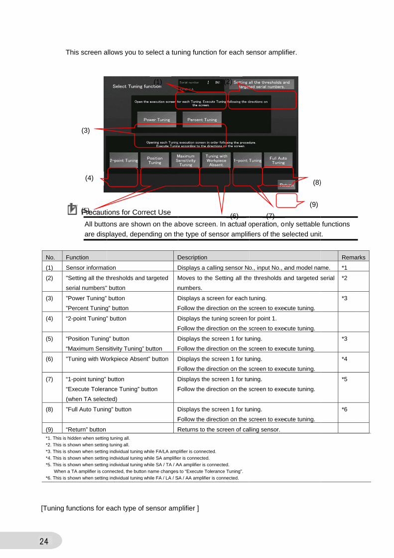
No. Function Description
(1) "Memory registration area"
button
Specifies an area in which you want to store memory on the PLC .
8 memory areas are provided.
(2) Operation button Performs the operation to the specified memory area.
Procedures)
Select an area and press the operation button.
After pressing the “Amplifier to Memory” or the “Memory to
Amplifier” button, a message and the operation progress counter
will be displayed in the status display area.
This processing is done when the message disappears after the
counter completes counting all the connected Units.
(3) “Clear memory” button Clears the stored memory information.
Procedures)
Select an area and press the operation button.
After pressing the “Clear memory” button, the following message
appears.
Press the “Yes” button to clear the memory.
This processing is done after the selected status is cleared.
(4) “Return” button Returns to the calling screen.

6-5 DeTh
m
pe
Function
> button
< button
“Return” b
Eco functi
Key lock f
Output mo
Detection
Indicator b
Initializing
setting
Threshold
Threshold
“Selecting
button
etailed Sehis screen a
ode, detecti
erforms the
button
ion
function
ode
function
blink
g sensor
d 1
d 2
g setting”
Addition
On the
You can
The exa
In actua
not disp
In the “
Precauti
etting Scallows you to
ion function,
indicator blin
Object
B
B
B
BL
BL
BL
BL
B
B
-
-
B
nal Informat
top of the sc
nnot change
ample scree
al operation,
played on th
“Object” co
ions for Cor
reen 1 o display the
, and to cha
nk and initia
Description
Moves to the
3 for a certain
Moves to the
3 for a certain
Return to the
Displays the
The indicator
If a lights-off
light blue.
Executes eac
This instructio
You can chan
clicking in the
Moves to the
tion
creen, the s
e the set val
en above sho
, function bu
e screen.
olumn above
rect Use
e current valu
nge these s
alizes senso
e Detailed Sett
n model of am
e Detailed Sett
n model of am
e Monitor scre
status of curre
r in blue indica
button is pres
ch operation.
on cannot ind
nge the set va
e numerical di
e Settings Sele
tatus of the
ue there.
ows all the f
uttons unset
e, B stands f
ue of the eco
ettings. It al
r setting.
tings Screen 2
mplifiers).
tings Screen 4
mplifiers).
en.
ent setting.
ates the curren
ssed, the settin
icate the statu
alue using a nu
isplay area.
ection Display
selected se
function butt
ttable by the
for Button, L
o function, k
so sets the
2 (Moves to th
4(Moves to the
nt setting.
ng changes, a
us (i.e. lightnin
umeric keypad
.
nsor amplifi
tons that can
connected
for Lamp, a
key lock func
threshold 1
he Detailed Se
e Detailed Set
and the chang
ng in blue).
d that is displa
ier is display
n be set on
sensor amp
and BL for B
31
ction, output
and 2, and
ettings Screen
ttings Screen
ed button will
ayed by
yed.
the screen.
plifiers are
utton Lamp.
t
.

32
If selecting, executing, or inputting the functions or values that are not supported by the
sensor amplifiers, the following screen appears.
In this case, the setting will
not be reflected.

6-6 DeTh
di
an
Function
> button
< button
“Return” b
Digital Dis
Timer Fun
Inverted D
Zero Rese
Emitting O
Timer Tim
Timer Tim
etailed Sehis screen a
splay, and t
nd emitting O
button
splay
nction
Display
et
OFF
me 1
me 2
Precaut
When a
as there
Addition
In the “
etting Scallows you to
o change th
OFF.
Object De
B Mo
B Mo
B Re
BL Dis
The
If a
blu
BL
BL
B Exe
ThiB
- Dis
Yo
the
-
ions for Cor
a TA-series a
e is no setta
nal Informat
“Object” co
reen 2 o display the
hese settings
scription
oves to the De
oves to the De
turn to the Mo
splays the stat
e indicator in b
a lights-off butt
e.
ecutes each o
is instruction c
splays the valu
u can change
e numerical dis
rrect Use
amplifier is s
able item.
tion
olumn above
e current valu
s. It also set
etailed Settings
etailed Settings
onitor screen.
tus of current
blue indicates
ton is pressed
operation.
cannot indicat
ue of current s
the set value
splay area.
selected, the
e, B stands f
ue of the dig
ts the timer t
s Screen 3.
s Screen 1.
setting.
s the current se
d, the setting c
e the status (i
setting.
using a nume
e Detailed S
for Button, L
gital display,
time, and pe
etting.
hanges, and t
.e. lightning in
eric keypad tha
Settings Scre
for Lamp, a
timer functi
erforms the z
the changed b
n blue).
at is displayed
een 2 is not
and BL for B
33
on, inverted
zero reset
button will light
d by clicking in
displayed
utton Lamp.
d
t
n
.

34
6-7 Detailed Setting Screen 3 This screen allows you to display the current values of the percent/ power tuning settings and
connecting head, and to change these settings. It also sets the percent, power tuning level,
hysteresis width, and executes the DPC function, keep setting, background removal.
Function Object Description
> button B Moves to the Detailed Settings Screen 4 (Detailed Settings Screen 1 for certain
model of amplifiers).
< button B Moves to the Detailed Settings Screen 2 (Detailed Settings Screen 1 for certain
model of amplifiers).
“Return” button B Return to the Monitor screen.
Power tuning setting BL Displays the status of current setting.
The indicator in blue indicates the current setting.
If a lights-off button is pressed, the setting changes, and the changed button will
light blue.
Percent tuning setting BL
Connecting head BL
DPC function B Executes each operation.
This instruction cannot indicate the status (i.e. lightning in blue). Keep setting B
Background removal B
Power tuning level - Displays the value of current setting.
You can change the set value using a numeric keypad that is displayed by
clicking in the numerical display area.
Percent tuning level -
Hysteresis width setting -
Hysteresis width IN1 -
Hysteresis width IN2 -
Additional Information
The example screen above shows all the function buttons that can be set on the screen.
In actual operation, function buttons unsettable by the connected sensor amplifiers are
not displayed on the screen.
In the “Object” column above, B stands for Button, L for Lamp, and BL for Button Lamp.

6-8 DeTh
pr
tu
Function
> button
< button
“Return” b
Direction s
Selecting
Setting to
Preset
Tolerance
Tolerance
Preset Va
etailed Sehis screen a
reset, setting
ning high an
button
setting
output
use origin
e Tuning High
e Tuning Low
alue
Precaut
On the
For this
amplifie
Addition
In the “
Precaut
Some s
Settings
etting Scallows you to
g to use orig
nd low, and
Object
B
B
B
BL
BL
BL
BL
-
-
-
ions for Cor
Detailed Se
s reason, this
er is connect
nal Informat
“Object” co
ions for Cor
sensor ampl
s Screens 1
reen 4 o display the
gin, and to c
preset value
Description
Moves to th
Moves to th
Return to th
Displays th
The indicat
If a lights-o
will light blu
Displays th
You can ch
clicking in t
rrect Use
etting Screen
s Detailed S
ted.
tion
olumn above
rrect Use
ifiers do not
to 4.
e current val
hange these
e.
n
he Detailed Se
he Detailed Se
he Monitor scr
e status of cu
tor in blue indi
off button is pre
ue.
e value of cur
hange the set v
the numerical
n 4, you can
Setting Scree
e, B stands f
t support the
ue of the dir
e settings. It
ettings Screen
ettings Screen
reen.
rrent setting.
cates the curr
essed, the set
rrent setting.
value using a
display area.
n only chang
en 4 can be
for Button, L
e functions t
rection settin
t also sets th
n 1.
n 3.
rent setting.
tting changes,
numeric keyp
ge settings o
displayed o
for Lamp, a
hat can be s
ng, selecting
he execute t
, and the chan
pad that is disp
of TA-series
only when a
and BL for B
set on the D
35
g output,
tolerance
nged button
played by
amplifiers.
TA-series
utton Lamp.
Detailed
.

36
Detailed Setting Screen 1
Function FA LA SA TA AA Remarks
Eco function OK OK OK OK OK
Indicator blink OK OK OK OK OK
Key lock function OK OK OK OK OK
Output mode OK OK OK OK *2
Threshold 1 IN1 OK OK OK OK OK
Threshold 2 IN1 OK OK OK OK *2
Detection function OK OK OK OK OK
Initializing sensor setting OK OK OK OK OK
Detailed Setting Screen 2
Function FA LA SA TA AA Remarks
Digital display OK OK *1 *2 *1 Including the solution viewer (button
key on topside of the amplifier)
Timer Function OK OK OK *2 *2
Timer Time 1 OK OK OK *2 *2
Timer Time 2 OK OK OK *2 *2
Zero reset OK OK OK *2 *2
Emitting OFF OK OK OK *2 *2
Inverted display OK OK OK *2 OK
Detailed Setting Screen 3
Function FA LA SA TA AA Remarks
Hysteresis width setting OK OK OK OK OK
Hysteresis width IN1 OK OK OK *2 OK
Hysteresis width IN2 OK OK OK OK OK
Power tuning setting OK OK *2 *2 *2
Power tuning level OK OK *2 *2 *2
Percent tuning setting OK OK *2 *2 *2
Percent tuning level OK OK *2 *2 *2
DPC function OK OK *2 *2 *2
Keep setting *2 *2 OK *2 *2
Background removal *2 *2 OK *2 *2
Connecting head *2 *2 OK *2 *2
*1: Some functions that can be set on the screen are not supported by the sensor amplifier.
*2: This function is not supported by the sensor amplifier. Accordingly, corresponding detailed
settings screen will not be displayed.
Additional Information

37
You can display a Setting All Detailed Setting Screen by pressing the “All Detailed Settings”
button at the top of the Monitor screen.
Differences from a Detailed Settings Screen, which is moved by pressing the “MODE” button on
the Monitor screen of each sensor amplifier, are shown below.
・The sensor status and current value are not highlighted.
・The “Selecting setting” button is not displayed (Detailed Settings Screen1).
・The “Setting all the thresholds and targeted serial numbers” button is displayed (Detailed
Settings Screen1).

38
6-9 Settings Selection Display This screen allows you to store various setting information for the selected sensor amplifier to
the PLC memory. It is also used to write information to the sensor amplifier.
Additional Information
The button framed in green indicates a memory area in which information is stored.
Select a memory area to perform the operation by pressing a toggle button.
* You cannot select multiple buttons simultaneously.
First release the button currently being selected, and then select another button.
With the select workpiece, the following information can be stored to the memory or written to
the amplifiers. ・Threshold 1 Input 1, Input 2 ・Threshold 2 Input 1 ・Operation mode
・Detection function ・Timer function ・Timer time 1
・Timer time 2 ・Zero reset ・Hold mode function
・Percent tuning setting ・Percent tuning level ・DPC function
・Power tuning setting ・Power tuning level ・Output mode
・Hysteresis width setting ・Hysteresis width 1 ・Hysteresis width 2
On the top of the screen, the status of the selected sensor amplifier is displayed.
You cannot change the set value there.
(4)
(3) (2)
(1)
39
No. Function Description
(1) “Memory registration area”
button
Specifies an area in which you want to store memory on the PLC .
8 memory areas are provided.
(2) Operation button Performs the operation to the specified memory area.
Procedures)
Select an area and press the operation button.
After pressing the “Amplifier to Memory” or the “Memory to
Amplifier” button, a message and the operation progress counter
will be displayed in the status display area.
This processing is done when the message disappears after the
counter completes counting all the connected Units.
(3) “Clear memory” button Clears the stored memory information.
Procedures)
Select an area and press the operation button.
After pressing the “Clear memory” button, the following message
appears.
Press the “Yes” button to clear the memory.
This processing is done after the selected status is cleared.
(4) “Return” button Returns to the calling screen.

40
6-10 TTh
gr
No. F
(1) T
(2) B
g
(3) G
(4) “
(5) “
Trend Grhis screen a
raph.
Function
Trend graph sc
Button for colle
graph data
Graph scaling
Log” button
Return” button
raph Screallows you to
creen
ecting
n
(2)
een o display the
Description
Displays the
sensor ampli
Performs the
A button to st
This button is
The indicator
collecting.
A button to st
You can use
Changes a g
You can sele
Moves to the
Return to the
e threshold a
logged data o
fier as a graph
e operation to t
tart the log co
s automatically
r on the right s
top the log co
the scroll butt
raph scaling.
ect from a mag
e Display Tren
e Monitor scre
(2)
and incident
of threshold (S
h.
the specified m
ollection
y tuned ON w
side of the scr
llection
tons while the
gnification of X
d Graph log s
en.
(4)
light of each
SV) and incide
memory area.
hen the scree
een turns ON
logging is sto
X1, X2, X4,X8,
creen (see the
(2)
h sensor am
ent light (PV) fo
.
en is displayed
while the log
opped.
,X10, and X 5
e next page).
(5)
)
mplifier as a
or each
d.
is
50.
(1)
(2)
(3)

41
Additional Information
On the top of the screen, the status of the selected sensor amplifier is displayed. You cannot
change the set value there.

42
No. Function Description
(5) Scroll UP/Down Scrolls up/down to display data by pressing this button.
Press and hold down this button, data can be automatically scrolled
up/down by one log.
(6) “Return” button Moves to the Trend Graph Screen.
Additional Information
The following data can be logged.
・The maximum peak bottom value that is logged one day before the updated data.
・The peak bottom value at the incident light is determined to be alarmed.
The latest logged data is shown at the bottom.
The most recent 30 logs can be monitored.
(6)
(5)
(5)

43
Additional Information
Concept of alarm
peak/bottom difference
Judgment example)
Peak
Alarm range Threshold
Bottom
Alarm range: A value falls below either “Difference between threshold and peak” or “Difference between threshold and bottom”
Peak
Alarm range
Bottom
Alarm value: 5500
Threshold: 5000
Value for judgement: 4500
“Difference between peak and threshold” /Threshold Example) (9000-5000)/5000=0.8⇒80%OK
(7500-5000)/5000=0.5⇒50%OK
(5200-5000)/5000=0.04⇒4%NG
For example, if alarm warning is performed when threshold is 5000 and at±10%.
Alarm is output when threshold is in range from 4500 to 5500.
“Difference between threshold and bottom” /Threshold Example) (5000-100)/5000=0.98⇒98%OK
(5000-3000)/5000=0.4⇒40%OK
(5000-4900)/5000=0.02⇒2%NG
* Once the above condition is met even for a short time, alarm is output but the error status is not maintained. Note)
・When a value falls within the alarm range, error log is output, and the indicator color on the main screen
changes to yellow. If the value goes to the normal range shortly afterward, the indicator returns to green which shows the normal status.
・An error log is output only once when the value goes into the alarm range from the normal range.

44
6-11 STh
It
No. F
(1) I
a
(2) S
ta
(3) F
(4) “
Setting Ahis screen a
is also used
Function
nput all thresh
and operation
Selection of al
argeted units
Function butto
Return” button
Precaut
When a
value is
Unlike i
amplifie
by defa
When a
written
case, fi
“ENT” k
(2)
All Threshallows you to
d to select al
Obje
holds
mode
B
L
l B
n B
n B
ions for Cor
a disconnect
s set.
individual se
er. Regardle
ault.
attempting to
to the unit s
rst press “C
key.
holds ando set all thres
ll units targe
ct Descrip
Sets the
・To inp
the nu
・To cha
Selects/When sappeare
Perform
・The ”S
disconn
・If a du
Returns
all tunin
rrect Use
ted unit is se
etting, all set
ess of thresh
o set the sam
simply by pre
LR” key to c
Selectinsholds and
eted for the o
ption
e threshold an
ut a threshold
merical displa
ange the opera
/unselects unselecting unitsed next to the
ms the operatio
Select all” an
nected unit.
mmy unit is se
s to the calling
ng function).
elected, a co
tting does n
hold for sens
me threshold
essing the “E
clear the valu
g All Targoperation m
operation.
nd operation m
, use a numer
ay area.
ation mode, p
its by pressing, refer to the munit No. butto
on stated on th
nd ”Reverse”
et, ”Not conn
g screen (Sett
ommand err
ot display th
sor amplifier
d to another
ENT” key us
ue, input the
(3)
geted Semodes.
mode of each i
ric keypad that
ress the ▲ b
g the unit No. model name ofon.
he button to th
operations ar
ected” is disp
ing all Detaile
ror doesn’t a
he current st
, D_ON is se
r targeted un
sing the num
e same value
erial Num
input.
t is displayed
button.
button. of the connecte
he selected un
re not perform
played.
ed Settings Sc
appear even
tatus of each
et for opera
nit, the value
meric keypad
e, and then
(4
(1
bers
by touching in
ed amplifier
nits.
med to the
creen 1/Select
n though a
h sensor
tion mode
e cannot be
d. In this
presses the
)
)
n
t
e

6-12 PTh
m
co
No. F
(1) “
(2) N
(3) C
n
Pop-up Shis screen a
onitored. It i
onnected to
Function
Return” button
Node address
Connection
node list
Precaut
Node N
connec
In some
contain
Setup ”
Screen foallows you to
is also used
the Controll
Descript
n Closes t
Displays
You can
clicking
* An err
Displays
(Up to 2
ions for Cor
No. of all the
ction node lis
e optional en
ed. Make su
page in the
r EtherCAo display and
to display t
er.
tion
his screen and
s the node add
n change the
in the numeric
ror message a
s the node add
1 node addres
rrect Use
EtherCAT s
st.
nvironments
ure that the
e Sysmac St
AT NODEd change th
the node add
d returns to th
dress No. to b
set value us
cal display are
appears if any
dresses of the
sses can be d
slaves conne
s, EtherCAT
set node No
tudio.
E Switchie node addr
dresses of t
he Menu scree
e monitored.
sing a numer
ea.
value that is o
EtherCAT sla
displayed)
ected to the
slaves othe
o. is for E3N
ng ress of the E
he EtherCAT
en.
ric keypad tha
outside the ran
aves connecte
Controller a
er than E3NW
W-ECT on t
EtherCAT sl
AT slaves tha
at is displaye
nge is entered
ed to the Contr
are displaye
W-ECT may
the” Configu
(3)
45
ave to be
at are
ed by
d.
roller.
ed in the
y be
urations and
(1)
(2)
d

46
6-13 Pop-up Screen for Language Switching This screen allows you to switch language to be displayed.
No. Function Description
(1) Japanese Switches the language on the buttons or labels into Japanese.
(2) English Switches the language on the buttons or labels into English.
(3) Chinese (Simplified) Switches the language on the buttons or labels into Chinese.
(4) Korean Switches the language on the buttons or labels into Korean.
(5) “Return” button Closes this screen and returns to the Menu screen.
Additional Information
Select a button of national flag to switch a language.
(1)
(2)
(3)
(4)
(5)

47
7 Startup Procedure
This section describes the procedure for connecting the NJ, various types of sensor amplifiers,
and NA to use the E3NW-ECT Window.
For the connection configuration, refer to 4-1 Device Configuration.
7-1 Procedure Take the following steps to start the system.
6-2 Building the System Configuration Connect the NJ, sensor amplifiers, and NA with
EtherNet cables.
↓
Connecting the NJ to sensor amplifiers Connect the NJ to each sensor amplifier via
EtherCAT.
↓
Connecting the NJ to NA Connect the NJ to NA via the switching hub.
↓
6-3 Setting and Transferring the
Project Data
Transfer the project file to the NJ and NA.
↓
Starting the Sysmac Studio and
importing the project file
Start the Sysmac Studio and import the project file.
↓
Checking the communication setting
and executing the build
Check the communication setting and program for
project data and execute the build.
↓
Connecting online and transferring the
project
Connect the Sysmac Studio online and transfer the
project data to the NJ and NA.
↓
Operating the screen After transferring the project data, check for normal
operation of each screen.

48
7-2 BuTh
1 Atta
the ”
Com
Afte
Amp
Ethe
side
an E
3 Con
hub.
4 In th
conn
hub.
Con
Ethe
5 Turn
the N
swit
uilding thhis section e
ch Sensor A
”E3NW-ECT
mmunication
r attaching t
plifier Units,
erCAT port o
e of the E3NW
EtherNet cab
nnect the NJ
.
he same way
nect the NA
.
nnect the sw
ernet port 1
n ON the po
NJ, NA, E3N
ching hub.
he Systeexplains how
Amplifier Un
T” Sensor
n Unit.
the Sensor
connect the
of NJ to the
W-ECT port
ble.
to the switc
y as step 3,
to the switc
itching hub t
of NA.
wer supplies
NW-ECT, an
em Confiw to connect
its to
e
“IN”
t with
ching
ching
to the
s to
nd
gurationt each devic
n ce and build
・
the system configuratioon.

49
7-3 Setting and Transferring the Project Data This section explains how to import, set, and transfer the project data.
1 Start the Sysmac Studio.
After starting the Sysmac
Studio, click the “Import” button
to import a project file.
3 Select the project file to import.
In this example,
”E3NW_NA_9inch.smc2” file is
selected.
4 Open the project of the NJ.
Select ”PLC_NJ3_0” from the
pull-down menu of Multiview
Explorer.
5 Check a node address in the
EtherCAT Tab Page of the
Sysmac Studio, and set the
rotary switch of the E3NW-ECT
to match the node address of
the project.
Node address is set to “100”
here.

50
6 Click
Setu
->”B
to ch
TCP
IP a
“192
7 Click
Con
“F8”
mak
norm
If a b
the p
mes
Tab
agai
8 Con
Sele
click
butto
the N
Afte
that
9 Ope
Sele
pull-
Exp
10 Click
Setu
the
Sett
IP a
”192
k ” Configura
up ”->”Contr
Built-in Ether
heck the IP
P/IP Settings
ddress is se
2.168.250.1”
k ”Project ”-
ntroller” or pr
” key to exec
ke sure that
mally.
build error o
project by fo
ssage displa
Page, and
in.
nnect the NJ
ect “Synchro
k the “Transf
on to transfe
NJ.
r the transfe
no error exi
en the projec
ect ” HMI_NA
-down menu
lorer.
k” Configura
up”->”HMI S
IP address i
tings.
ddress is se
2.168.250.2”
ations and
roller Setup”
rNet/IP Setti
address in
s.
et to
” here.
>”Build
ress down th
cute build an
build ends
occurs, corre
ollowing the
ayed in the B
executes bu
online with
onization” an
fer to Contro
er the projec
er, make sur
ists in the N
ct of the NA.
A5_0” from
u of Multiview
ations and
Settings” to c
in TCP/IP
et to
” here.
ng”
he
nd
ect
Build
uild
PC.
nd
oller”
ct to
re
J.
.
the
w
check

51
11 Click ”Project ”->”Build HMI” or
press down the “F8” key to
execute build and make sure
that build ends normally.
If a build error occurs, correct
the project by following the
message displayed in the Build
Tab Page.
12 Click “HMI”->”Online” to connect
the NA online with PC.
If OS for the NA needs to be
updated, a pop-up will appear.
Follow the direction to update
OS.
13 Select “Synchronization” and
click the “Transfer to Device”
button to transfer the project to
the NA.
If OS was updated in step 12,
connect the NA online with PC
again, perform the
synchronization, and transfer
the project to the NA.

52
8 P
8-1 OvThis All th
・P
Progr
verview section des
he variables
Precaut
The com
indicate
device
Program con
1st node of E3N
NA (part
Communicatio(Sensor ampInternal inform
SDO
instruct
Trend Graph
Variab
(for
Varia
ram
cribes detaiand program
ions for Cor
mmunication
ed in Section
performance
nfiguration
NW-ECT Comm
ially Visual Ba
Variarequope
PD
PDO com
on Unit plifiers) mation
O ion
h Screen
le for graph
all Units)
able mapping [
[Ex1s
ls of the proms appeared
rrect Use
n with this p
n 4-1; howev
e or possible
unication Unit
asic program i
Monitor scr
Display ar
V
(
able for uesting eration
DO mappingallocated variable
mmunications
External variab
NJ IO mappingxternal variable st node: 24 Units
ograms usedd in this sec
rogram has
ver, the ope
e disturbanc
ncluded )
reen
[External v
rea
Variable for display
(for 6 Units)
le 4]
1 ]s
2nd node
Commu(SensoInternal
SDO in
d in the E3Nction have be
been check
ration is not
ce such as e
NJ ST prog
variable 3 ]
Variable will chaccod
behavior ochan
of E3NW-ECT C
PDO
nication Unitr amplifiers) information
nstruction
W-ECT Wineen set in th
ked using the
guaranteed
electrical noi
ram
to refer ange
dig to of screen ges
Communication
PDO mappallocatedvariable
O communicatio
NJ IO mapp[External varia2nd node: 24
ndow projecthe project of
e device co
d due to varia
ise.
Variable fo
controlling P
(for 24 Unit
[External
variable 2
n Unit
ping d e
ons
ping able 1 ]
Units
t for NA. f the NJ.
nfiguration
ations in the
or
PLC
ts)
l
]
e

53
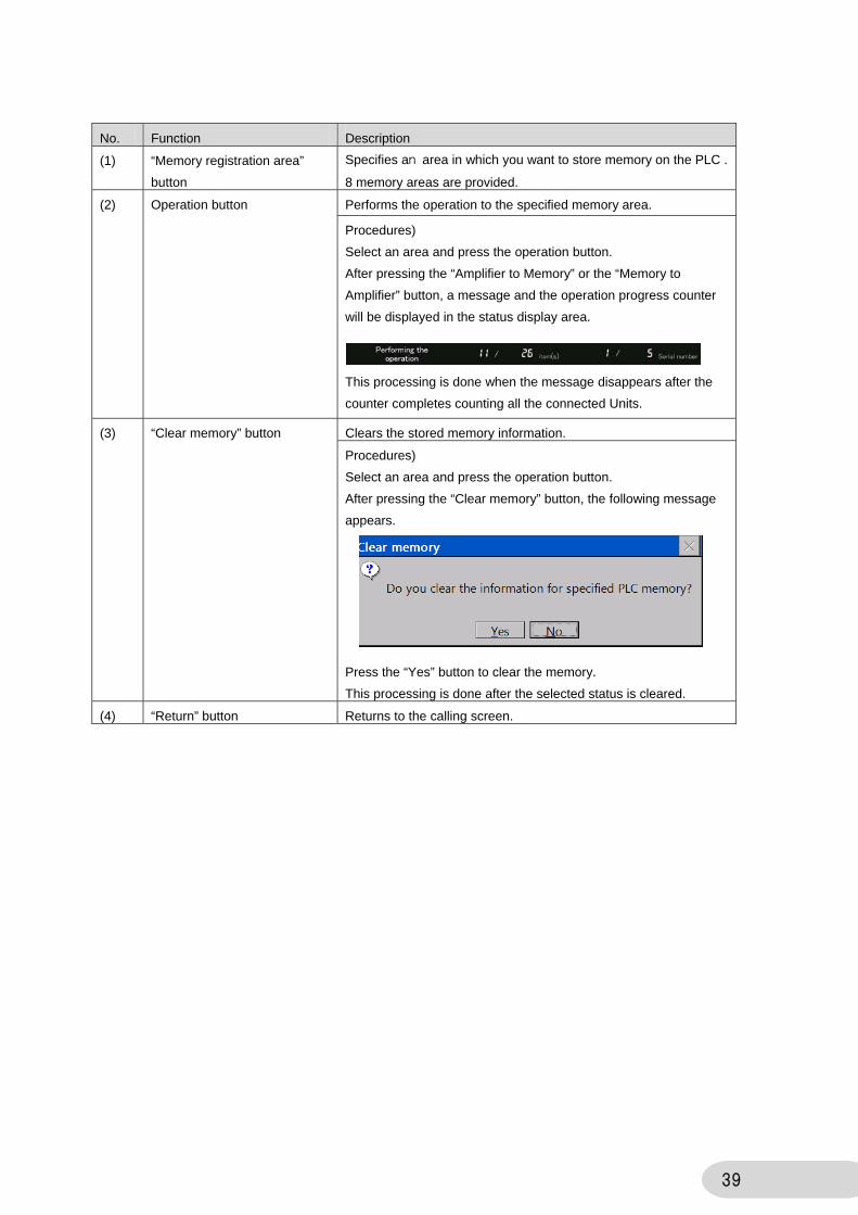
PDO mapping The PDO mapping used in this program is given below. In addition to the default mapping setting for E3NW-ECT Communication Unit, the sensor detection level for 24 sensor amplifiers (Input 1 only, 4 byte included) are assigned as PV values. This allows the corresponding sensor amplifiers to obtain PV values without depending on the connected position.
No. PDO mapping to send Factory setting of
Communication Unit
Setting of this programNo. PDO entry
1 257 Read input 1st word OK OK 2 258 Read input 2nd word OK OK 3 259 Read input 3rd word - OK 4 260 Read input 4th word - - 5 265 Status of Sensor Communications OK OK 6 267 Number of sensors to be set OK OK 7 268 Sensor warning status OK OK 8 273 Unit No. 01 sensor detection level IN1 OK OK 9 274 Unit No. 01 sensor detection level IN2 - -
10 275 Unit No. 02 sensor detection level IN1 OK OK 11 276 Unit No. 02 sensor detection level IN2 - - 12 277 Unit No. 03 sensor detection level IN1 OK OK 13 278 Unit No. 03 sensor detection level IN2 - - 14 279 Unit No. 04 sensor detection level IN1 OK OK 15 280 Unit No. 04 sensor detection level IN2 - - 16 281 Unit No. 05 sensor detection level IN1 OK OK 17 282 Unit No. 05 sensor detection level IN2 - - 18 283 Unit No. 06 sensor detection level IN1 OK OK 19 284 Unit No. 06 sensor detection level IN2 - - 20 285 Unit No. 07 sensor detection level IN1 OK OK 21 286 Unit No. 07 sensor detection level IN2 - - 22 287 Unit No. 08 sensor detection level IN1 OK OK 23 288 Unit No. 08 sensor detection level IN2 - - 24 289 Unit No. 09 sensor detection level IN1 - OK 25 290 Unit No. 09 sensor detection level IN2 - - 26 291 Unit No. 10 sensor detection level IN1 - OK 27 292 Unit No. 10 sensor detection level IN2 - - 28 293 Unit No. 11 sensor detection level IN1 - OK 29 294 Unit No. 11 sensor detection level IN2 - - 30 295 Unit No. 12 sensor detection level IN1 - OK 31 296 Unit No. 12 sensor detection level IN2 - - 32 297 Unit No. 13 sensor detection level IN1 - OK 33 298 Unit No. 13 sensor detection level IN2 - - 34 299 Unit No. 14 sensor detection level IN1 - OK 35 300 Unit No. 14 sensor detection level IN2 - - 36 301 Unit No. 15 sensor detection level IN1 - OK 37 302 Unit No. 15 sensor detection level IN2 - - 38 303 Unit No. 16 sensor detection level IN1 - OK 39 304 Unit No. 16 sensor detection level IN2 - - 40 305 Unit No. 17 sensor detection level IN1 - OK No. PDO mapping to send Factory setting of
Communication Unit Setting of this programNo. PDO entry

54
41 306 Unit No. 17 sensor detection level IN2 - - 42 307 Unit No. 18 sensor detection level IN1 - OK 43 308 Unit No. 18 sensor detection level IN2 - - 44 309 Unit No. 19 sensor detection level IN1 - OK 45 310 Unit No. 19 sensor detection level IN2 - - 46 311 Unit No. 20 sensor detection level IN1 - OK 47 312 Unit No. 20 sensor detection level IN2 - - 48 313 Unit No. 21 sensor detection level IN1 - OK 49 314 Unit No. 21 sensor detection level IN2 - - 50 315 Unit No. 22 sensor detection level IN1 - OK 51 316 Unit No. 22 sensor detection level IN2 - - 52 317 Unit No. 23 sensor detection level IN1 - OK 53 318 Unit No. 23 sensor detection level IN2 - - 54 319 Unit No. 24 sensor detection level IN1 - OK 55 320 Unit No. 24 sensor detection level IN2 - - 56 321 Unit No. 25 sensor detection level IN1 - - 57 322 Unit No. 25 sensor detection level IN2 - - 58 323 Unit No. 26 sensor detection level IN1 - - 59 324 Unit No. 26 sensor detection level IN2 - - 60 325 Unit No. 27 sensor detection level IN1 - - 61 326 Unit No. 27 sensor detection level IN2 - - 62 327 Unit No. 28 sensor detection level IN1 - - 63 328 Unit No. 28 sensor detection level IN2 - - 64 329 Unit No. 29 sensor detection level IN1 - - 65 330 Unit No. 29 sensor detection level IN2 - - 66 331 Unit No. 30 sensor detection level IN1 - - 67 332 Unit No. 30 sensor detection level IN2 - - 68 333 Unit No. 01 threshold 1 IN1 - -○ 69 334 Unit No. 01 threshold 2 IN1 - - 70 335 Unit No. 01 threshold 1 IN2 - -○ 71 336 Unit No. 02 threshold 1 IN1 - -○ 72 337 Unit No. 02 threshold 2 IN1 - - 73 338 Unit No. 02 threshold 1 IN2 - -○ 74 339 Unit No. 03 threshold 1 IN1 - -○ 75 340 Unit No. 03 threshold 2 IN1 - - 76 341 Unit No. 03 threshold 1 IN2 - -○ 77 342 Unit No. 04 threshold 1 IN1 - -○ 78 343 Unit No. 04 threshold 2 IN1 - - 79 344 Unit No. 04 threshold 1 IN2 - -○ 80 345 Unit No. 05 threshold 1 IN1 - -○ 81 346 Unit No. 05 threshold 2 IN1 - - 82 347 Unit No. 05 threshold 1 IN2 - -○ 83 348 Unit No. 06 threshold 1 IN1 - -○ 84 349 Unit No. 06 threshold 2 IN1 - - 85 350 Unit No. 06 threshold 1 IN2 - -○ 86 351 Unit No. 07 threshold 1 IN1 - -○ 87 352 Unit No. 07 threshold 2 IN1 - - 88 353 Unit No. 07 threshold 1 IN2 - -○ No. PDO mapping to send Factory setting of
Communication Unit Setting of this programNo. PDO entry

55
89 354 Unit No. 08 threshold 1 IN1 - -○ 90 355 Unit No. 08 threshold 2 IN1 - -- 91 356 Unit No. 08 threshold 1 IN2 - -○- 92 357 Unit No. 09 threshold 1 IN1 - -○ 93 358 Unit No. 09 threshold 2 IN1 - -- 94 359 Unit No. 09 threshold 1 IN2 - -○- 95 360 Unit No. 10 threshold 1 IN1 - -○ 96 361 Unit No. 10 threshold 2 IN1 - -- 97 362 Unit No. 10 threshold 1 IN2 - -○- 98 363 Unit No. 11 threshold 1 IN1 - -○ 99 364 Unit No. 11 threshold 2 IN1 - -- 100 365 Unit No. 11 threshold 1 IN2 - -○- 101 366 Unit No. 12 threshold 1 IN1 - -○ 102 367 Unit No. 12 threshold 2 IN1 - -- 103 368 Unit No. 12 threshold 1 IN2 - -○- 104 369 Unit No. 13 threshold 1 IN1 - -○ 105 370 Unit No. 13 threshold 2 IN1 - -- 106 371 Unit No. 13 threshold 1 IN2 - -○- 107 372 Unit No. 14 threshold 1 IN1 - -○ 108 373 Unit No. 14 threshold 2 IN1 - -- 109 374 Unit No. 14 threshold 1 IN2 - -○- 110 375 Unit No. 15 threshold 1 IN1 - -○ 111 376 Unit No. 15 threshold 2 IN1 - -- 112 377 Unit No. 15 threshold 1 IN2 - -○- 113 378 Unit No. 16 threshold 1 IN1 - -○ 114 379 Unit No. 16 threshold 2 IN1 - -- 115 380 Unit No. 16 threshold 1 IN2 - -○- 116 381 Unit No. 17 threshold 1 IN1 - -○ 117 382 Unit No. 17 threshold 2 IN1 - -- 118 383 Unit No. 17 threshold 1 IN2 - -○- 119 384 Unit No. 18 threshold 1 IN1 - -○ 120 385 Unit No. 18 threshold 2 IN1 - -- 121 386 Unit No. 18 threshold 1 IN2 - -○- 122 387 Unit No. 19 threshold 1 IN1 - -○ 123 388 Unit No. 19 threshold 2 IN1 - -- 124 389 Unit No. 19 threshold 1 IN2 - -○- 125 390 Unit No. 20 threshold 1 IN1 - -○ 126 391 Unit No. 20 threshold 2 IN1 - -- 127 392 Unit No. 20 threshold 1 IN2 - -○- 128 393 Unit No. 21 threshold 1 IN1 - -○ 129 394 Unit No. 21 threshold 2 IN1 - -- 130 395 Unit No. 21 threshold 1 IN2 - -○- 131 396 Unit No. 22 threshold 1 IN1 - -○ 132 397 Unit No. 22 threshold 2 IN1 - -- 133 398 Unit No. 22 threshold 1 IN2 - -○- 134 399 Unit No. 23 threshold 1 IN1 - -○ 135 400 Unit No. 23 threshold 2 IN1 - -- No. PDO mapping to send Factory setting of
Communication Unit
Setting of this programNo. PDO entry

56
136 401 Unit No. 23 threshold 1 IN2 - -○-- 137 402 Unit No. 24 threshold 1 IN1 - -○ 138 403 Unit No. 24 threshold 2 IN1 - --- 139 404 Unit No. 24 threshold 1 IN2 - -○-- 140 405 Unit No. 25 threshold 1 IN1 - - 141 406 Unit No. 25 threshold 2 IN1 - --- 142 407 Unit No. 25 threshold 1 IN2 - -- 143 408 Unit No. 26 threshold 1 IN1 - - 144 409 Unit No. 26 threshold 2 IN1 - -- 145 410 Unit No. 26 threshold 1 IN2 - - 146 411 Unit No. 27 threshold 1 IN1 - - 147 412 Unit No. 27 threshold 2 IN1 - - 148 413 Unit No. 27 threshold 1 IN2 - - 149 414 Unit No. 28 threshold 1 IN1 - - 150 415 Unit No. 28 threshold 2 IN1 - - 151 416 Unit No. 28 threshold 1 IN2 - - 152 417 Unit No. 29 threshold 1 IN1 - - 153 418 Unit No. 29 threshold 2 IN1 - - 154 419 Unit No. 29 threshold 1 IN2 - - 155 420 Unit No. 30 threshold 1 IN1 - - 156 421 Unit No. 30 threshold 2 IN1 - - 157 422 Unit No. 30 threshold 1 IN2 - - 158 423 Unit No. 01 sensor detection level
(4byte) - OK
159 424 Unit No. 02 sensor detection level (4byte)
- OK
160 425 Unit No. 03 sensor detection level (4byte)
- OK
161 426 Unit No. 04 sensor detection level (4byte)
- OK
162 427 Unit No. 05 sensor detection level (4byte)
- OK
163 428 Unit No. 06 sensor detection level (4byte)
- OK
164 429 Unit No. 07 sensor detection level (4byte)
- OK
165 430 Unit No. 08 sensor detection level (4byte)
- OK
166 431 Unit No. 09 sensor detection level (4byte)
- OK
167 432 Unit No. 10 sensor detection level (4byte)
- OK
168 433 Unit No. 11 sensor detection level (4byte)
- OK
169 434 Unit No. 12 sensor detection level (4byte)
- OK
170 435 Unit No. 13 sensor detection level (4byte)
- OK
171 436 Unit No. 14 sensor detection level (4byte)
- OK
172 437 Unit No. 15 sensor detection level (4byte)
- OK
No. PDO mapping to send Factory setting of Communication Unit
Setting of this programNo. PDO entry

173
174
175
176
177
178
179
180
181
182
183
184
185
186
187
188
3 438
439
5 440
6 441
7 442
8 443
9 444
445
446
447
3 448
449
5 450
6 451
7 452
8 512
Precaut
When c
to be w
of the s
Unit(4byUnit(4byUnit(4byUnit(4byUnit(4byUnit(4byUnit(4byUnit(4byUnit(4byUnit(4byUnit(4byUnit(4byUnit(4byUnit(4byUnit(4bySys
ions for Cor
changing PD
within the ma
sensor ampli
t No. 16 syte) t No. 17 senyte) t No. 18 senyte) t No. 19 senyte) t No. 20 senyte) t No. 21 senyte) t No. 22 senyte) t No. 23 senyte) t No. 24 senyte) t No. 25 senyte) t No. 26 senyte) t No. 27 senyte) t No. 28 senyte) t No. 29 senyte) t No. 30 senyte) mac error st
rrect Use
DO mapping
apping memo
ifiers to be m
sensor dete
sor detectio
sor detectio
sor detectio
sor detectio
sor detectio
sor detectio
sor detectio
sor detectio
sor detectio
sor detectio
sor detectio
sor detectio
sor detectio
sor detectio
tatus
gs and conne
ory range, fo
monitored.
ection level
on level
on level
on level
on level
on level
on level
on level
on level
on level
on level
on level
on level
on level
on level
ecting 25 or
or instance,
-
-
-
-
-
-
-
-
-
-
-
-
-
-
-
O
more senso
by limiting t
-
-
-
-
-
-
-
-
-
-
-
-
-
-
-
OK
or amplifiers
the connecte
57
OK
OK
OK
OK
OK
OK
OK
OK
OK
-
-
-
-
-
-
OK
s, they need
ed position

58
8-2 Variables to Use ■ Variables to Use
This section lists data types, external variables (user-defined global variables), and internal variables used in this program.
● Data type (structure type)
Data types are registered by the NJ. They also can be used in the NA.
[Amplifier information for controlling inside PLC]
Name Data type Description
AMP_Status STRUCT A structure of amplifier information
Amp_Name STRING[30] A name of amplifier
Name_In1 STRING[30] Function In1
Name_In2 STRING[30] Function In2
Led_In1 BOOL LED In1
Led_In2 BOOL LED In2
Led_ST BOOL LED ST
Led_DPC BOOL LED DPC
L_D_Select_In1 BOOL Function setting IN1
L_D_Select_In2 BOOL Function setting IN2
SV_In1 DINT Threshold IN1
SV_In2 DINT Threshold IN2
PV_IN1 DINT Incident light IN1
PV_IN2 DINT Incident light IN2
PV_IN1_4byte DINT Incident light 4byte IN1
Amp_Index UINT Amplifier index
Amp_Disp_Index UINT Amplifier display No.
Amp_Active BOOL Amplifier_enable/disable
DPC_Label WORD DPC label indication
Head_Flg INT Connecting head information (SA only)
W_Level UINT Warning level
DPC_Amp_Error BOOL Error in DPC amplifier
DPC_Calc_Error_P BOOL DPC peak calculation error
DPC_Calc_Error_B BOOL DPC bottom calculation error
[Trend graph log information]
Name Data type Description
LOG_DISP STRUCT Log information
Log_Date STRING[20] Log date
Peek DINT Peak value
Btm DINT Bottom value
Peek_Sa DINT Peak difference
Botm_Sa DINT Bottom difference
ErrLog_Time STRING[10] Error log time string
ErrLog_Mes DINT Error log message FLG
ErrLog_Assy STRING[50] Error log message display area

59
[Memory information of workpiece selection, setting selection]
Name Data type Description
AMP_WORK STRUCT Work memory information
Data_Set BOOL Data setting FLG
Threshold1_IN1 DINT Threshold 1 IN1
Threshold1_IN2 DINT Threshold 1 IN2
Threshold 2_IN1 DINT Threshold 2 IN1
Output_Mode_IN1 UINT Output mode IN1
Output_Mode_IN2 UINT Output mode IN2
Operating_Mode_IN1 UINT Operation modeIN1
Operating_Mode_IN2 UINT Operation modeIN2
Detect_Fnc UINT Detection function
Timer_Fnc_IN1 UINT Timer functionIN1
Timer_Fnc_IN2 UINT Timer functionIN2
Timer_1_IN1 UINT Timer 1 IN1
Timer_1_IN2 UINT Timer 1 IN2
Timer_2_IN1 UINT Timer 2 IN1
Timer_2_IN2 UINT Timer 2 IN2
DPC_Set UINT DPC setting
Hysteresis_Width_Set UINT Hysteresis width setting
Hysteresis_Width1_IN1 UDINT Hysteresis width 1_IN1
Hysteresis_Width1_IN2 UDINT Hysteresis width 1_IN2
Hysteresis_Width2_IN1 UDINT Hysteresis width 2_IN1
HoldMode_Set UINT Hold mode setting
Zero_Reset UINT Zero reset
Percent_Tunn_Set_IN1 UINT Percent tuning set_IN1
Percent_Tunn_Set_IN2 UINT Percent tuning set_IN2
Percent_Tunn_Level_IN1 INT Percent tuning level_IN1
Percent_Tunn_Level_IN2 INT Percent tuning level_IN2
Power_Tunn_Set UINT Power tuning set
Power_Tunn_Level UDINT Power tuning level
[Amplifier information for displaying the NA main monitor]
Name Data type Description
AMP_Status_Main STRUCT A structure of amplifier information
Amp_Index UINT Amplifier index
Led_In1 BOOL LED In1
Led_In2 BOOL LED In2

60
[Amplifier information for displaying the status of NA sensor amplifiers]
Name Data type Description
AMP_Status_Set STRUCT A structure of amplifier information
Led_ST BOOL LED ST
Led_DPC BOOL LED DPC
DPC_Label WORD DPC label indication
Led_In1 BOOL LED In1
Led_In2 BOOL LED In2
Amp_Index UINT Amplifier index
Amp_Disp_Index UINT Amplifier display No.
L_D_Select_In1 BOOL Function setting IN1
L_D_Select_In2 BOOL Function setting IN2
SV_In1 DINT Threshold IN1
SV_In2 DINT Threshold IN2
PV_IN1 DINT Incident light IN1
PV_IN2 DINT Incident light IN2
61
●External variable 1
[Global variables to be allocated to the used slave] Node No. 100
Name Data type Description
Allocation
status
PDO NA
E001_Read_input_1st_word WORD Input bits 00 to 15 OK -
E001_Read_input_2nd_word WORD Input bits 16 to 31 OK -
E001_Read_input_3rd_word WORD Input bits 32 to 47 OK -
E001_Sensor_Communication_Status BYTE Sensor communication status 8bit OK -
E001_Number_of_Sensors_Setting USINT Number of sensors to be set OK -
E001_Number_of_Sensors_with_Dummy USINT Number of sensors (including
dummy)
OK -
E001_Sensor_Warning_Status DWORD Sensor warning status OK -
E001_No_01_Detection_Level_IN1 INT Unit No. 01 sensor detection level
IN1
OK -
: : : : :
E001_No_24_Detection_Level_IN1 *1 INT Unit No. 24 sensor detection level
IN1 *1
OK -
E001_No_01_Threshold_1_Settings_IN1 DINT Unit No. 01 threshold 1 IN1 - -
E001_No_01_Threshold_1_Settings_IN2 DINT Unit No. 01 threshold 1 IN2 - -
: : : : :
: : : : :
E001_No_24_Threshold_1_Settings_IN1
*1 DINT Unit No. 24 threshold 1 IN1 *1
- -
E001_No_24_Threshold_1_Settings_IN2
*1 DINT Unit No. 24 threshold 1 IN2 *1
- -
E001_No_01_Detection_Level_4byte DINT Unit No. 01 sensor detection level
(4byte)
OK -
: : : : :
E001_No_24_Detection_Level_4byte *1 DINT Unit No. 24 sensor detection level
(4byte) *1
OK -
E001_In_Bit00 BOOL Input bit 00 OK -
: : : : :
E001_In_Bit47 *1 BOOL Input bit 47 *1 OK -
E001_Sensor_Communication_Busy BOOL Sensor communication busy OK -
E001_Sensor_Communication_Error BOOL Sensor communication error OK -
E001_Sysmac_Error_Status BYTE Sysmac error status OK -
E001_Observation BOOL Error information at observation
level
OK -
E001_Minor_Fault BOOL Error information at minor fault level OK -
*1: Since Unit No. in the “Name” column is given in a row, subsequent Unit No. is omitted. Node No. 101

62
Name
E002_Read
E002_Read
E002_Read
E002_Sens
E002_Num
E002_Num
E002_Sens
E002_No_0
:
E002_No_2
E002_No_0
E002_No_0
E002_No_2
E002_No_2
E002_No_0
:
E002_No_2
E002_In_Bi
:
E002_In_Bi
E002_Sens
E002_Sens
E002_Sysm
E002_Obse
E002_Mino
*1: Since U
d_input_1st_w
d_input_2nd_w
d_input_3rd_w
sor_Communic
ber_of_Senso
ber_of_Senso
sor_Warning_S
01_Detection_
24_Detection_
01_Threshold_
01_Threshold_
:
: 24_Threshold_
24_Threshold_
01_Detection_
24_Detection_
it00
it47 *1
sor_Communic
sor_Communic
mac_Error_Sta
ervation
r_Fault
Unit No. in th
Addition
The “Al
PDO: "O
NA: "OK
Precaut
word
word
word
cation_Status
ors_Setting
ors_with_Dum
Status
_Level_IN1
_Level_IN1 *1
_1_Settings_I
_1_Settings_I
_1_Settings_I
_1_Settings_I
_Level_4byte
_Level_4byte *
cation_Busy
cation_Error
atus
he “Name” c
nal Informat
location stat
OK" indicate
K" indicates
ions for Cor
Da
W
W
W
BY
US
my US
DW
IN
IN
N1 DI
N2 DI
N1 *1 DI
N2 *1 DI
DI
*1 DI
BO
BO
BO
BO
BY
BO
BO
column is giv
tion
tus” column
es that the v
that the mu
rrect Use
ata type D
WORD In
WORD In
WORD In
YTE S
SINT N
SINT N
d
WORD S
NT U
IN
:
NT U
IN
INT U
INT U
:
:
INT U
INT U
INT U
(4
:
INT U
(4
OOL In
:
OOL In
OOL S
OOL S
YTE S
OOL E
le
OOL E
le
ven in a row
indicates th
variable is ta
utual commu
Description
nput bits 00 to
nput bits 16 to
nput bits 32 to
Sensor commu
Number of sen
Number of sen
ummy)
Sensor warning
Unit No. 01 sen
N1
Unit No. 24 sen
N1 *1
Unit No. 01 thre
Unit No. 01 thre
Unit No. 24 thre
Unit No. 24 thre
Unit No. 01 sen
4byte)
Unit No. 24 sen
4byte) *1
nput bit 00
nput bit 47 *1
Sensor commu
Sensor commu
Sysmac error s
Error informatio
evel
Error informatio
evel
, subsequen
he following;
argeted for P
unications w
15
31
47
unication statu
sors to be set
sors (including
g status
nsor detection
:
nsor detection
eshold 1 IN1
eshold 1 IN2
:
: eshold 1 IN1 *
eshold 1 IN2 *
nsor detection
:
nsor detection
:
unication busy
unication error
status
on at observat
on at minor fau
nt Unit No. is
PDO mappin
ith the NA a
Alloc
statu
PD
OK
OK
OK
us 8bit OK
t OK
g OK
OK
n level OK
:
n level OK
-
-
:
:
*1 -
*1 -
n level OK
:
n level OK
OK
:
OK
y OK
r OK
OK
tion OK
ult OK
s omitted.
ng.
are available
cation
us
DO NA
K -
K -
K -
K -
K -
K -
K -
K -
:
K -
- -
- -
:
: - -
- -
K -
:
K -
K -
:
K -
K -
K -
K -
K -
K -
e.

63
The variables for node 101 in this project are registered in the NJ’s global variables;
however, the EtherCAT slave is not registered, the allocation destination is left blank.
To use node 101, associate the variable by selecting ”Configurations and Setup ” ->”
I/O Map” in the NJ project of the Sysmac Studio.

64
●External variable 2
[Common variables for NJ/NA using user program NA/SDO non-reference]
Name Data type Description Allocation status
Retain SDO NA
g_BTM_ErrLog_Out BOOL Bottom error output flag -
g_DL_Chg_Act BOOL Inputting operation mode -
g_DPC_ErrLog_Out BOOL DPC error output -
G_FL_Chg_Act BOOL Inputting flashing operation -
g_Hysteresis_Low1_Chg BOOL Hysteresis width Low1 change OK
g_Multi_Active BOOL Disable/enable selecting all OK
g_PEK_ErrLog_Out BOOL Peak error output flag -
g_ProjLightOff_Act2 BOOL Emitting OFF execution IN2 OK
g_ProjLightOff_Can2 BOOL Emitting OFF cancel IN2 OK
g_PV_Ave BOOL PV value-average flag -
g_SDO_FIRST_READ BOOL SDO instruction read first time only -
g_SDO_READ BOOL SDO instruction read -
g_SDO_SET_READ BOOL SDO instruction read only for the setting
screen -
g_SV_Active BOOL SV value display update, stop flag -
g_SV_Chg_Act BOOL Inputting threshold by numeric keypad -
g_SV_UPDW BOOL Inputting threshold by + - key -
g_Sys_Start BOOL Start flag at startup OK
g_UNIT_Busy BOOL Communication Unit Busy -
g_BTM_ErrLog_No INT Bottom error output targeted unit -
g_DitectionFunc_Set INT Detection function setting information -
g_DPC_ErrLog_No INT DPC error output targeted unit -
g_PEK_ErrLog_No INT Peak error output targeted unit -
g_Write_Sk_In1 INT Threshold input 1 write value -
g_Write_Sk_In2 INT Threshold input 2 write value -
g_READ_Data LINT SDO read data -
g_SET_Data LINT SDO write data -
g_SET_DataSize UINT SDO data size -
g_SET_Index UINT SDO index -
g_Hysteresis_Low_IN1 UDINT Hysteresis Low IN1 OK
g_SET_SubIndex USINT SDO sub index -
g_MemViewer AMP_WORK Amplifier registration viewer OK
[Data type is array or structure]
Name Data type Description
Allocation status
Retai
n SDO NA
g_DL_ModeStatus_Active ARRAY[0..30] OF BOOL Operation mode LED show/hide OK
g_FL_ModeStatus_Active ARRAY[0..30] OF BOOL Flashing LED show/hide OK
g_FL_ModeStatus_IN1 ARRAY[0..30] OF BOOL Flashing operation status Input 1 OK

65
g_FL_ModeStatus_IN1_BL
INK ARRAY[0..30] OF BOOL Flashing blink IN1 -
g_FL_ModeStatus_IN2 ARRAY[0..30] OF BOOL Flashing operation status Input 2 OK
g_FL_ModeStatus_IN2_BL
INK ARRAY[0..30] OF BOOL Flashing blink IN2 -
g_GraphDisp ARRAY[0..30] OF BOOL Trend graph button display OK
g_Node_No_Select ARRAY[0..199] OF BOOL Node No. to be displayed -
g_DispSensorDat2 ARRAY[0..30] OF INT Information 2 of sensor amplifier
for displaying the screen OK
g_Graph_Range_HI ARRAY[0..30] OF DINT Upper limit of trend graph range OK
g_Graph_Range_Low ARRAY[0..30] OF DINT Lower limit of trend graph range OK
g_PV_Graph_IN1 ARRAY[0..30,0..1600] OF
DINT Incident light for graph IN1 -
g_PV_In1 ARRAY[0..30] OF DINT Incident lightInput 1 OK
g_PV_In1_2byte ARRAY[0..30] OF DINT 2 byte of incident light input 1 -
g_PV_In1_2byte_AVE ARRAY[0..30] OF DINT 2 byte average value of incident
light input 1 -
g_PV_In1_4byte ARRAY[0..30] OF DINT 4 byte of incident light input 1 -
g_PV_In1_Err_B ARRAY[0..30] OF DINT Bottom value when error occurs -
g_PV_In1_Err_P ARRAY[0..30] OF DINT Peak value when error occurs -
g_PV_In1_Max ARRAY[0..30] OF DINT Updating the maximum incident
light input 1 at each time -
g_PV_In1_Max_Day ARRAY[0..30] OF DINT Maximum incident light input 1 for
each day -
g_PV_In1_Min ARRAY[0..30] OF DINT Updating the minimum incident
light input 1 at each time -
g_PV_In1_Min_Day ARRAY[0..30] OF DINT Updating the minimum incident
light input 1 for each day -
g_PV_In1_Sa_B ARRAY[0..30] OF DINT Bottom difference Input 1 -
g_PV_In1_Sa_P ARRAY[0..30] OF DINT Peak difference input 1 -
g_PV_In2 ARRAY[0..30] OF DINT Incident light input 2 -
g_SV_Graph_IN1 ARRAY[0..30,0..1600] OF
DINT Threshold for graph IN1 -
g_SV_In1_ECT ARRAY[0..30] OF DINT Threshold input 1 obtain for each
node -
g_SV_In2_ECT ARRAY[0..30] OF DINT Threshold input 2 obtain for each
node -
g_SV_Key_In1 ARRAY[0..30] OF DINT Threshold screen input value 1 OK
g_SV_Key_In2 ARRAY[0..30] OF DINT Threshold screen input value 2 OK
g_Temp_PV_In1 ARRAY[0..30,0..100] OF
DINT [Unit , buffer for average] -
g_DPC_Label_Set ARRAY[0..30] OF WORD DPC ZERO label setting OK
g_GraphLogBuff ARRAY[0..30,0..30] OF
LOG_DISP
Buffer for operation log PV-value
[30 units, 30 logs] OK

66
Additional Information
The “Allocation status” column indicates the following;
Retain:"OK" indicates that the variable is to be retained.
SDO:”OK” indicates that the variable is to be obtained via SDO communications.
NA:"OK" indicates that the mutual communications with the NA are available.

67
●External variable3
[Common variables for NJ/NA using user program NA/SDO reference ]
Name Data type Description Allocation status
Retain SDO NA
g_DispBlink_Off1 BOOL Display blink cancel IN1 OK OK
g_DispBlink_On1 BOOL Display blink execution IN1 OK OK
g_DispDirect_1 BOOL Display direction normal OK OK
g_DispDirect_2 BOOL Display direction invert OK OK
g_DL_ModeCHG_IN1 BOOL Operation mode change input 1 OK OK
g_DL_ModeCHG_IN2 BOOL Operation mode change input 2 OK OK
g_FL_ModeCHG_IN1 BOOL Flashing operation change input 1 OK OK
g_FL_ModeCHG_IN2 BOOL Flashing operation change input 2 OK OK
g_Graph_Alarm_ChgFlg BOOL Alarm for trend graph Set value change
Flag OK OK
g_Graph_ loging BOOL Graph loging - OK
g_Graph_Scr_L_Full BOOL Move to start of graph 1 data - OK
g_Graph_Scr_L1 BOOL Graph 1 data move - OK
g_Graph_Scr_R_Full BOOL Move to end of graph 1 data - OK
g_Graph_Scr_R1 BOOL Graph 1 data move - OK
g_Graph_Scr_Reset BOOL Graph 1 data delete - OK
g_GraphDisp_Dwn BOOL Trend graph scroll down OK OK
g_GraphDisp_Up BOOL Trend graph scroll up OK OK
g_Hysteresis_Chg BOOL Hysteresis width change OK OK
g_Hysteresis_High_Chg BOOL Hysteresis width High change OK OK
g_Hysteresis_Low2_Chg BOOL Hysteresis width Low 2 change OK OK
g_Multi_OpMode_IN1 BOOL Operation mode IN1 for multi OK OK
g_Multi_OpMode_IN1_Color BOOL Operation mode IN1 display color for
multi OK OK OK
g_Multi_OpMode_IN2 BOOL Operation mode IN2 for multi OK OK
g_Multi_OpMode_IN2_Color BOOL Operation mode IN2 display color for
multi OK OK OK
g_Multi_Select_Cansel BOOL Selecting all clear all OK OK
g_Multi_Select_Rev BOOL Selecting all invert OK OK
g_Multi_Select_Set BOOL Selecting all OK OK
g_Multi_Set BOOL All detailed settings OK OK
g_Multi_Set_ON BOOL All detailed settings execution OK OK
g_Multi_SV_IN1_1_CHG BOOL Thresholds all IN1_1 input OK OK
g_Multi_SV_IN1_2_CHG BOOL Thresholds all IN1_2 input OK OK
g_Multi_SV_IN2_CHG BOOL Thresholds all IN2_ input OK OK
g_Multi_Tuning BOOL Tuning all OK OK
g_Multi_Tuning_ON BOOL Tuning all execution OK OK
g_Page_Next BOOL Move to next page - OK
g_Page_Prev BOOL Return to previous page - OK
g_PowerTun_Chg1 BOOL Power Tuning target value change1 OK OK
Name Data type Description Allocation status

68
Retain SDO NA
g_Priset_Data_Chg BOOL Preset value change - OK
g_ProjLightOff_Act1 BOOL Emitting OFF execution IN1 OK OK
g_ProjLightOff_Can1 BOOL Emitting OFF cancel IN1 OK OK
g_SensorInit BOOL Initializing sensor setting OK OK
g_SetSelect_Act BOOL Setting selection execution OK OK
g_SetSelect_AMP_To_PLC BOOL Storing the setting information of amplifier
to PLC memory OK OK
g_SetSelect_Disp BOOL Displaying operation progress of PLC
memory OK OK
g_SetSelect_MemClr BOOL PLC memory clear OK OK
g_SetSelect_No_Mem BOOL Storing the setting selection No. OK OK
g_SetSelect_PLC_To_AMP BOOL Storing the setting information of PLC
memory to amplifier OK OK
g_Sv_ChgFlg_In1 BOOL Threshold direct input change input 1 OK OK
g_Sv_ChgFlg_In2 BOOL Threshold direct input change input 2 OK OK
g_Sv_Down_In1 BOOL Threshold - Input 1 OK OK
g_Sv_Down_In2 BOOL Threshold - Input 2 OK OK
g_SV_In1_1_Chg BOOL Threshold IN1_1 change OK OK
g_SV_In1_2_Chg BOOL Threshold IN1_2 change OK OK
g_Sv_PreChgFlg_In1 BOOL Threshold direct input change advance
notice input 1 OK OK
g_Sv_PreChgFlg_In2 BOOL Threshold direct input change advance
notice input 2 OK OK
g_SV_RD_Pass BOOL Read value direct display flag - OK
g_Sv_Up_In1 BOOL Threshold + Input 1 OK OK
g_Sv_Up_In2 BOOL Threshold + Input 2 OK OK
g_Threshold_Chg1 BOOL Percent tuning change IN1 OK OK
g_Threshold_Chg2 BOOL Percent tuning change IN2 OK OK
g_TimerSet1_Chg1 BOOL Timer time 1 change 1 OK OK
g_TimerSet1_Chg2 BOOL Timer time 1 change 2 OK OK
g_TimerSet2_Chg1 BOOL Timer time 2 change 1 OK OK
g_TimerSet2_Chg2 BOOL Timer time 2 change 2 OK OK
g_tolerance_High_Chg BOOL Tolerance high value change - OK
g_tolerance_Low_Chg BOOL Tolerance low value change - OK
g_Tune_Power1 BOOL Power tuning execution OK OK
g_Tune_Wk1 BOOL Workpiece present/ absent tuning point 1 OK OK
g_Tuning_Exe BOOL Display FLG during tuning OK OK
g_Tuning_TextFlg1 BOOL Tuning message setting FLG OK OK
g_WorkSelect_Act BOOL Workpiece selection execution OK OK
g_WorkSelect_AMP_To_PLC BOOL Storing the work information of amplifier
to PLC memory OK OK
g_WorkSelect_Disp BOOL Displaying operation progress of PLC
memory OK OK
g_WorkSelect_MemClr BOOL PLC memory clear OK OK
Name Data type Description Allocation status

69
Retain SDO NA
g_WorkSelect_No_Mem BOOL Storing the workpiece selection No. OK OK
g_WorkSelect_PLC_To_AMP BOOL Storing the work information of PLC
memory to amplifier OK OK
g_ZeroReset_Color1 BOOL Zero reset button display color IN1 OK OK OK
g_ZeroReset_Color2 BOOL Zero reset button display color IN2 OK OK OK
g_ZeroReset_Off1 BOOL Zero reset cancel IN1 OK OK
g_ZeroReset_On1 BOOL Zero reset execution IN1 OK OK
g_goki_CNT INT Display unit setting - OK
g_Multi_SV_IN1_1 INT Thresholds all IN1_1 input OK OK OK
g_Multi_SV_IN1_2 INT Thresholds all IN1_2 input OK OK OK
g_Multi_SV_IN2 INT Thresholds all IN2 OK OK OK
g_PercentTun_Level_IN1 INT Percent tuning level IN1 OK OK OK
g_PercentTun_Level_IN2 INT Percent tuning level IN2 OK OK OK
g_SV_In1_1_Set INT Threshold input 1_1 OK OK OK
g_SV_In1_2_Set INT Threshold input 1_2 OK OK OK
g_Priset_Data DINT Preset value - OK OK
g_PV_In1_Max_Disp DINT Peak value input1 for screen display OK OK
g_PV_In1_Min_Disp DINT Bottom value input1 for screen display OK OK
g_tolerance_High DINT Tolerance high - OK OK
g_tolerance_Low DINT Tolerance low - OK OK
g_DL1_CallNo UINT D/L change IN1 call No. OK OK
g_DL2_CallNo UINT D/L change IN2 call No. OK OK
g_FL1_CallNo UINT Flashing operation change IN1 call No. OK OK
g_FL2_CallNo UINT Flashing operation change IN 2 call No. OK OK
g_Graph_Alarm_Disp UINT Alarm display value for trend graph OK OK
g_Graph_ED_No UINT Graph scale display end No. - OK
g_Graph_Scale UINT Interval for obtaining graph (scaling) - OK
g_Graph_ST_No UINT Graph scale display start No. - OK
g_Graph1_CallNo UINT Input 1 trend graph call No. OK OK
g_HMI_PageNo UINT HMI display page No. (from 0) - OK
g_Hysteresis_Set UINT Hysteresis width setting OK OK OK
g_MultiTuning_Message UINT Tuning all message FLG OK OK
g_NDA UINT Node address OK OK
g_SENSOR_CNT_Color UINT No. of the connected sensor status OK OK
g_Set_CallNo UINT Function settings screen calling unit No. OK OK
g_SetSelect_No UINT Setting selection No. OK OK
g_SV_CallNo UINT Threshold + - calling unit No. OK OK
g_SV_TenKey_In1 UINT Numeric keypad input IN1 OK OK
g_SV_TenKey_In2 UINT Numeric keypad input IN2 OK OK
g_Timer_Time1_In1 UINT Timer time 1 input 1 OK OK OK
g_Timer_Time1_In2 UINT Timer time 1 input 2 OK OK OK
g_Timer_Time2_In1 UINT Timer time 2 input 1 OK OK OK
g_Timer_Time2_In2 UINT Timer time 2 input 2 OK OK OK
Name Data type Description Allocation status
Retain SDO NA
70
g_Tune1_CallNo UINT Input 1tuning call No. OK OK
g_Tune2_CallNo UINT Input 2tuning call No. OK OK
g_Tuning_IN_Message UINT Tuning input port OK OK
g_Tuning_Message UINT Tuning function message FLG OK OK
g_WorkSelect_No UINT Workpiece selection No. OK OK
g_Hysteresis_High UDINT Hysteresis high OK OK OK
g_Hysteresis_Low_IN2 UDINT Hysteresis low IN2 OK OK OK
g_PowerT_Target_In1 UDINT Power Tuning target value input 1 OK OK OK
g_SENSOR_CNT USINT No. of the connected sensors OK OK
g_SetSelect_All USINT PLC memory setting selection
number of operations OK OK
g_SetSelect_CNT USINT PLC memory setting selection
operation progress counter OK OK
g_WorkSelect_All USINT PLC memory Workpiece selection
number of operations OK OK
g_WorkSelect_CNT USINT PLC memory Workpiece selection
operation progress counter OK OK
g_WorkSelect_GokiCNT USINT PLC memory Workpiece selection
operation progress unit counter OK OK
g_DispName STRING[50] Display name OK OK
g_Pop_DispName STRING[50] Pop-up display name NJ request OK OK
g_Pop_NA_DispName STRING[50] Pop-up display name NA operation OK OK [Data type is array or structure]
Name Data type Description Allocation status
Retain SDO NA
g_AMPHead ARRAY[0..2] OF BOOL Sensor connected amplifier head OK OK
g_AMPHead_Color ARRAY[0..2] OF BOOL Status of sensor amplifier head OK OK
g_BackDel ARRAY[0..5] OF BOOL Background removal OK OK
g_BackDel_Color ARRAY[0..5] OF BOOL Background removal button
display color OK OK OK
g_direction_Color ARRAY[0..2] OF BOOL Direction setting display color - OK OK
g_direction_Select ARRAY[0..2] OF BOOL Direction setting - OK
g_DispDirect_Color ARRAY[0..5] OF BOOL Direction setting button display
color OK OK OK
g_DispMode ARRAY[0..20] OF BOOL Display mode OK OK
g_DispMode_Color ARRAY[0..20] OF BOOL Display mode button display
color OK OK OK
g_DispSensor_Active ARRAY[0..30] OF BOOL Checking the sensor amplifier
implementation - OK
g_DitectFunc_Color ARRAY[0..10] OF BOOL Detection function button display
color OK OK
g_DitectionFunction ARRAY[0..10] OF BOOL Detection function OK OK
g_DL_ModeStatus_Active_
HMI ARRAY[0..6] OF BOOL Operation mode show/hide HMI - OK

71
g_DL_ModeStatus_IN1_H
MI ARRAY[0..6] OF BOOL
Operation mode status input 1
HMI - OK
g_DL_ModeStatus_IN2_H
MI ARRAY[0..6] OF BOOL
Operation mode status input 2
HMI - OK
g_DPC_Led_status_HMI ARRAY[0..6] OF BOOL DPC LED status HMI - OK
g_DPC_SetMode1 ARRAY[0..10] OF BOOL DPC setting IN1 OK OK
g_DPC_SetMode1_Color ARRAY[0..10] OF BOOL DPC setting IN1 button display
color OK OK
g_EcoMode ARRAY[0..5] OF BOOL ECO mode OK OK
g_EcoMode_Color ARRAY[0..5] OF BOOL ECO mode button display color OK OK OK
g_FL_ModeStatus_Active_
HMI ARRAY[0..6] OF BOOL
Flashing operation LED
show/hide HMI - OK
g_FL_ModeStatus_IN1_H
MI ARRAY[0..6] OF BOOL
flashing operation status input 1
HMI - OK
g_FL_ModeStatus_IN1_H
MI_BLINK ARRAY[0..6] OF BOOL Flashing blink IN1 HMI - OK
g_FL_ModeStatus_IN2_H
MI ARRAY[0..6] OF BOOL
flashing operation status input 2
HMI - OK
g_FL_ModeStatus_IN1_H
MI_BLINK ARRAY[0..6] OF BOOL Flashing blink IN2 HMI - OK
g_GraphDisp_HMI ARRAY[0..6] OF BOOL Trend graph button display HMI - OK
g_KeepSet ARRAY[0..5] OF BOOL Keep setting OK OK
g_KeepSet_Color ARRAY[0..5] OF BOOL Keep setting button display color OK OK OK
g_KeyLock ARRAY[0..5] OF BOOL Key lock function OK OK
g_KeyLock_Color ARRAY[0..5] OF BOOL Key lock function button display
color OK OK OK
g_Multi_Select_Ctrl ARRAY[0..30] OF BOOL Selecting all unit selection OK OK
g_Multi_Select_Ctrl_HMI ARRAY[0..6] OF BOOL Selecting all unit selection HMI - OK
g_Origin_Color ARRAY[0..2] OF BOOL Setting to use origin display color - OK OK
g_Origin_Select ARRAY[0..2] OF BOOL Setting to use origin - OK
g_Output_Color ARRAY[0..2] OF BOOL Selecting output display color - OK OK
g_Output_Select ARRAY[0..2] OF BOOL Selecting output - OK
g_OutPutMode2 ARRAY[0..10] OF BOOL Output mode IN2 OK OK
g_OutPutMode1_Color ARRAY[0..10] OF BOOL Output mode IN1 display color OK OK OK
g_OutPutMode1 ARRAY[0..10] OF BOOL Output mode IN1 OK OK
g_OutPutMode2_Color ARRAY[0..10] OF BOOL Output mode IN2 display color OK OK OK
g_PercentTun_IN1 ARRAY[0..5] OF BOOL Percent tuning setting IN1 OK OK
g_PercentTun_IN1_Color ARRAY[0..5] OF BOOL Percent tuning setting display
color IN1 OK OK OK
g_PercentTun_IN2 ARRAY[0..5] OF BOOL Percent tuning setting IN2 OK OK
g_PercentTun_IN2_Color ARRAY[0..5] OF BOOL Percent tuning setting display
color IN2 OK OK OK
g_PowerTun_Set ARRAY[0..5] OF BOOL Power tuning setting OK OK
g_PowerTun_Set_Color ARRAY[0..5] OF BOOL Power Tuning display color OK OK OK
g_Priset_Color ARRAY[0..2] OF BOOL Preset setting display color - OK OK
g_Priset_Select ARRAY[0..2] OF BOOL Preset setting - OK

72
g_SET1_Visibility ARRAY[0..9] OF BOOL Setting 1 item display - OK
g_SET2_Visibility ARRAY[0..9] OF BOOL Setting 2 item display - OK
g_SET3_Visibility ARRAY[0..9] OF BOOL Setting 3 item display - OK
g_SET4_Visibility ARRAY[0..9] OF BOOL Setting 4 item display - OK
g_SetMemory_ACT ARRAY[0..10] OF BOOL Setting selection status OK OK
g_SetSelect ARRAY[0..10] OF BOOL Setting selection - OK
g_ST_Led_status_HMI ARRAY[0..6] OF BOOL ST LED status HMI - OK
g_TimerFunc1_Color ARRAY[0..10] OF BOOL Timer function IN1 display
color OK OK OK
g_TimerFunc2_Color ARRAY[0..10] OF BOOL Timer function IN2 display
color OK OK OK
g_TimerFunction1 ARRAY[0..10] OF BOOL Timer function IN1 OK OK
g_TimerFunction2 ARRAY[0..10] OF BOOL Timer function IN2 OK OK
g_Tuning_ActFlg ARRAY[0..5] OF BOOL Tuning disable/enable FLG OK OK
g_WorkMemory_ACT ARRAY[0..10] OF BOOL Workpiece memory status
[10 memories] OK OK
g_WorkSelect ARRAY[0..10] OF BOOL Workpiece selection - OK
g_DispSensorDat1 ARRAY[0..30] OF INT Sensor amplifier information 1
for displaying screen OK OK OK
g_DispSensorDat1_HMI ARRAY[0..6] OF INT Sensor amplifier information1 for
displaying HMI screen - OK
g_PV_HMI ARRAY[0..1600] OF
DINT Incident light for displaying HMI - OK
g_PV_In1_HMI ARRAY[0..6] OF DINT Incident light input 1 HMI - OK
g_PV_In2_HMI ARRAY[0..6] OF DINT Incident light input 2 HMI - OK
g_SV_HMI ARRAY[0..1600] OF
DINT Threshold for displaying HMI - OK
g_SV_In1 ARRAY[0..30] OF DINT ThresholdInput 1 OK OK
g_SV_In1_HMI ARRAY[0..6] OF DINT ThresholdInput 1 HMI - OK
g_SV_In2 ARRAY[0..30] OF DINT ThresholdInput 2 OK OK
g_SV_In2_HMI ARRAY[0..6] OF DINT ThresholdInput 2 HMI - OK
g_Node_No ARRAY[0..199] OF
STRING[10] Recognized node No. - OK
g_USER_AMP_Name ARRAY[0..30] OF
STRING[50] User function name OK OK
g_USER_AMP_Name_HM
I
ARRAY[0..6] OF
STRING[50] User function name HMI - OK
g_DMY_AMP ARRAY[0..30] OF BYTE Dummy amplifier information OK OK OK
g_DPC_Label_Set_HMI ARRAY[0..6] OF WORD DPC ZERO label setting HMI - OK
g_GraphStatus_IN1_HMI ARRAY[0..6] OF WORD Graph LED lighting status IN1
HMI - OK
g_SetSelect_SetFlg ARRAY[0..10] OF WORD Setting selection status flag OK OK
g_WorkSelect_SetFlg ARRAY[0..10] OF WORD Workpiece selection status flag OK OK
g_AMP_HMI ARRAY[0..6] OF
AMP_Status_Main
HMI to display amplifier
information Only - OK

73
g_Set_AMP ARRAY[0..1] OF
AMP_Status_Set
Amplifier information for setting
screen OK OK OK
g_GraphDispBuff ARRAY[0..10] OF
LOG_DISP Buffer for trend graph OK OK
g_DL_ModeStatus_IN1 ARRAY[0..30] OF BOOL Operation mode status input 1 OK OK
g_DL_ModeStatus_IN2 ARRAY[0..30] OF BOOL Operation mode status input 2 OK OK
g_DPC_Led_status ARRAY[0..30] OF BOOL DPC LED status OK OK
g_ST_Led_status ARRAY[0..30] OF BOOL ST LED status OK OK
g_Temp_Sk_In1 ARRAY[0..30] OF INT Threshold input 1 - OK
g_Temp_Sk_In2 ARRAY[0..30] OF INT Threshold input 2 - OK
g_GraphStatus_IN1 ARRAY[0..30] OF WORD Graph LED lighting status IN1 OK OK
g_AMP ARRAY[0..30] OF
AMP_Status Amplifier information all units OK OK
g_SetMemory ARRAY[0..10] OF
AMP_WORK Setting selection information OK OK
g_WorkMemory ARRAY[0..30,0..10] OF
AMP_WORK
Workpiece memory information
[30 units, 10 memories] OK OK
Additional Information
The “Allocation status” column indicates the following;
Retain:"OK" indicates that the variable is to be retained.
SDO:”OK” indicates that the variable is to be obtained via SDO communications.
NA:"OK" indicates that the mutual communications with the NA are available.

74
●External variable 4
[NA using user program only]
Name Data type Description
Allocation
status
SDO NA
AMP_30_Disp Boolean Unit No. 30 display flag - OK
g_Multi_Btn_ON Boolean All buttons ON - OK
g_NDA_Chg Boolean Node address change - OK
g_TA_AMP_SetMenu Boolean Operation flag when using TA-series
amplifiers - OK
HMI_DL_ModeCHG_IN1 Boolean Operation mode change input 1 - OK
HMI_DL_ModeCHG_IN2 Boolean Operation mode change input 2 - OK
HMI_FL_ModeCHG_IN1 Boolean Flashing operation mode change input 1 - OK
HMI_FL_ModeCHG_IN2 Boolean Flashing operation mode change input 2 - OK
keyClose Boolean Close the key - OK
Minus Boolean With/without sign - OK
OverMax Boolean Exceeding input upper limit flag - OK
UnderMin Boolean Exceeding input lower limit flag - OK
ValEnter Boolean Value enter flag - OK
Multi_AMPHead_Color Boolean(1) Sensor connected amplifier head status - OK
Multi_BackDel_Color Boolean(1) Background removal button display color - OK
Multi_direction_Color Boolean(1) Detection function button display color - OK
Multi_DispDirect_Color Boolean(1) Direction setting button display color - OK
Multi_DPC_SetMode1_Color Boolean(1) DPC setting IN1 button display color - OK
Multi_KeepSet_Color Boolean(1) Keep setting button display color - OK
Multi_KeyLock_Color Boolean(1) Key lock function button display color - OK
Multi_Origin_Color Boolean(1) Setting to use origin display color - OK
Multi_Output_Color Boolean(1) Selecting output display color - OK
Multi_PercentTun_IN1_Color Boolean(1) Percent tuning setting display color IN1 - OK
Multi_PercentTun_IN2_Color Boolean(1) Percent tuning setting display color IN2 - OK
Multi_PowerTun_Set_Color Boolean(1) Power tuning setting display color - OK
Multi_Priset_Color Boolean(1) Preset setting display color - OK
Multi_ZeroReset_Color Boolean(1) Zero reset button display color - OK
Multi_EcoMode_Color Boolean(2) ECO mode button display color - OK
Multi_OutPutMode2_Color Boolean(2) Output mode IN2 display color - OK
Multi_DitectFunc_Color Boolean(3) Detection function button display color - OK
Multi_OutPutMode1_Color Boolean(3) Output mode IN1 display color - OK
Multi_TimerFunc1_Color Boolean(4) Timer function IN1 button display color - OK
Multi_TimerFunc2_Color Boolean(4) Timer function IN2 button display color - OK
g_select_Lang Boolean(10) Language selection - OK
Multi_DispMode_Color Boolean(10) Display mode button display color - OK
g_Bef_NDA UShort Node address before change - OK
g_Multi_CallNo UShort Call No. when operating all. - OK
g_NDA_CHK UShort Node address shortly after input - OK
g_SetSelect_No_HMI UShort Setting selection No. - OK
75
g_Tune_Act_CallNo UShort Tuning call No. - OK
g_WorkSelect_No_HMI UShort Workpiece selection No. - OK
HMI_DL1_CallNo UShort D/L change IN1 call No. - OK
HMI_DL2_CallNo UShort D/L change IN2 call No. - OK
HMI_FL1_CallNo UShort Flashing operation change IN1 call No. - OK
HMI_FL2_CallNo UShort Flashing operation change IN2 call No. - OK
HMI_Multi_CallNo UShort Call No. when operating all. - OK
HMI_Set_CallNo UShort Detail setting call No. - OK
HMI_SV_CallNo UShort Threshold + - calling unit No. - OK
HMI_SV_TenKey_In1 UShort Numeric keypad input IN1 - OK
HMI_SV_TenKey_In2 UShort Numeric keypad input IN2 - OK
HMI_Tune1_CallNo UShort Input 1 tuning call No. - OK
HMI_Tune2_CallNo UShort Input 2 tuning call No. - OK
Setting1_timerSet Integer Timer Time setting No. - OK
DataDisplayID UInteger Data display identification No - OK
ViewInt UInteger Integer of display digit - OK
KeybordInput Double Converting user input to numerical value - OK
Maxval Double Upper limit input - OK
Minval Double Lower limit input - OK
g_Disp_RetName String Return display name - OK
g_Multi_Disp_RetName String Return display name when operating all - OK
PreHMI_CurrentPage String Screen before transition - OK
UserInputError String Input value for error display - OK
g_Log_Text String(9) Graph log text - OK
Additional Information
The “Allocation status” column indicates the following;
SDO:”OK” indicates that the variable is to be obtained via SDO communications.
NA:"OK" indicates that the mutual communications with the NA are available.

76
■
M
g_PV
g_SV
g_SV
g_
g_
g_
■ Example o
The followin
Precaut
The abo
for devi
In actua
NA
Monitor screen
V_In1_HMI[0
V_In1_HMI[0
V_In2_HMI[0
Variables to
according to th
Trend graph _PV_In1[0~2
_SV_In1[0~2
_SV_In2[0~2
They are con
a
of variable a
ng diagram
ions for Cor
ove diagram
ices.
al operation,
n to 5]
to 5]
to 5]
o refer will chan
he screen switc
23] 23] 23]
nstantly commun
as trend graph
allocation
shows a flow
rrect Use
m shows an e
, refer to var
NJ ST p
g_PV_In1
g_SV_In1
g_SV_In2
ge
ching.
nicated, and dis
in the NA
w from input
example of
riable names
program 1I[0 to 23] 1I[0 to 23] 2I[0 to 23]
splayed
Substi
v
t ports of PV
variable nam
s that are al
E
N
No_
No_
N
No_
No_
tute into array
variable
V value and
mes and how
located to th
E3NW Commu
I/O m
No_01_Detect
_01_Threshold
_01_Threshold
,
,
,
,
No_24_Detect
_24_Threshold
_24_Threshold
y
Allocate to P
and aqui
SV value to
w to substitu
he actual fun
unication Unit
map tion_Level_IN
d_1_Settings_
d_1_Settings_
, , , , tion_Level_IN
d_1_Settings_
d_1_Settings_
PDO mapping
ire values
o NA.
ute values
nction.
t
1 _IN1 _IN2
1 _IN1 _IN2

77
8-3 Program in ST Language ■ Functional configurations of the program This program is written in ST language. The functional configurations are listed below.
Task E3NW_MAIN
Function Acquires information of system configuration. Controls the pages on the Monitor screen. Updates information of the sensor amplifiers within the display range.
FB None
Line Description Detail
1-51 Processing for specified node Specifies the location to refer for each node.
52-128 First time setup at start-up Sets the initial value and initializes variables.
129-148 Network configuration check Checks the node address recognized by the system.
149-156 TIMER processing Sets various timer functions.
157-236
First time operation at system start-up
Reads information of the connected amplifier.
Writes the initial value to the trend graph-related variable.
237-364
Display update of each read value
Updates the data collections according to the selected main monitor screen.
Always updates values to display within the display range.
Task PANEL_INPUT
Function Responds to button operation on the Monitor screen. * Changes SV value (Entry with a numeric keypad, or [ + ][-] key). Switch an operation mode.
FB Press_Hold_Button, SDO_WRITE_OBJ
Line Description Detail
1-50 First time setup at start-up Sets the initial value and initializes variables.
51-70 TIMER processing Sets various timer functions.
71-184 Flashing input Prepares to issue a control command according to the input status of flashing function.
185-276 Operation mode input Prepares to issue a control command according to the status of input operation mode.
277-388 Check of write value inputted by numeric keypad
Checks whether or not to write the value inputted by numeric keypad.
389-910 Check of write value inputted by [+][-] keys
・Checks whether or not to write the value inputted by [+][-] keys.
(input by next button cannot be accepted until processing of
the pressed button ends)
・Checks whether or not to shift the digit to be changed when
inputting value by the [+][-] keys. The digit to be changed is shifted by every 20 times you pressed the button in a row (use of FB)
911-990 Operation upon SDO instruction write completion
Writes the operation results.
991-1002 This is the execution part of SDO writing function.
Task PDO_PV_SV_IO
Function Substitutes the input information of the Unit mapped to PDO into the display variables.
FB None
Line Description Detail
1-47 First time setup at start-up Sets the initial value and initializes variables.
48-580 Updating constantly Obtains the PV-value, SV-value, and input status.

78
*Average is performed 100 times for PV-value.
Whether or not to use 4byte of PV value, the model of amplifiers are referred.
Reads the value according to the status and conditions of drawing update.
Substitute the IN state to the display variable.
Task SDO_FIRST_READ
Function This is operated at system startup for the first time. Acquires the connection information (amplifier type, dummy information ). This operation is disabled for disconnected Units.
FB SDO_READ_OBJ
Line Description Detail
1-24 First time setup at start-up Sets the initial value and initializes variables.
25-252 SDO instruction read Reads the status of dummy setting and model of sensor amplifier.
253-264 This is the execution part of SDO writing function.
Task SDO_AMP_READ
Function
Acquires information of sensor amplifiers that are displayed on the Monitor screen and various setting screen. (PDO information excluded) Operation mode status. LED status. While the target screen is being displayed, communications are always established and screen information is updated.
FB SDO_READ_OBJ
Line Description Detail
1-33 First time setup at start-up Sets the initial value and initializes variables.
34-297 SDO instruction read Reads the sensor status of operation mode.
298-308 This is the execution part of SDO writing function.
Task SET_DISP1
Function Only when an entry is made on the screen while the Detailed Settings Screen 1 is being displayed, executes the corresponding operation (setting all included) .
FB SDO_READ_OBJ , SDO_WRITE_OBJ
Line Description Detail
1-35 First time setup at start-up Sets the initial value and initializes variables.
36-48 Multi setting check Performs the flag setting when inputting multi setting.
49-66 Screen operation
Initializes the displayed information on the screen. (P0030_Detailed Settings Screen 1 excluded)
67-85 Screen operation Initializes the variables shortly after changing the screen.
85-99 (P0030_Detailed Settings Screen 1 only)
Prepares to issue a control command according to the status of each input button and input value.
100-283 Reads the current set value shortly after changing the screen.
284-611 Writes each setting according to the instruction selected by each button.
612-675 This is the execution part of SDO reading/writing FB.
Task SET_DISP2
Function Only when an entry is made on the screen while the Detailed Settings Screen 2 is being displayed, executes the corresponding operation (setting all included)
FB SDO_READ_OBJ , SDO_WRITE_OBJ
Line Description Detail

79
1-35 First time setup at start-up Sets the initial value and initializes variables.
36-53 Screen operation
Initializes the displayed information on the screen. (P0031_Detailed Settings Screen 2 excluded)
54-72 Screen operation Initializes the variables shortly after changing the screen.
73-86 (P0031_Detailed Settings Screen 2 only)
Prepares to issue a control command according to the status of each input button and input value.
87-310 Reads the current set value shortly after changing the screen.
311-787 Writes each setting according to the instruction selected by each button.
788-813 This is the execution part of SDO reading/writing FB.
Task SET_DISP3
Function Only when an entry is made on the screen while the Detailed Settings Screen 3 is being displayed, executes the corresponding operation (setting all included).
FB SDO_READ_OBJ , SDO_WRITE_OBJ
Line Description Detail
1-34 First time setup at start-up Sets the initial value and initializes variables.
35-54 Screen operation
Initializes the displayed information on the screen. (P0032_Detailed Settings Screen 3 excluded)
55-77 Screen operation Initializes the variables shortly after changing the screen.
78-86 (P0032_Detailed Settings Screen 3 only)
Prepares to issue a control command according to the status of each input button and input value.
87-347 Reads the current set value shortly after changing the screen.
348-824 Writes each setting according to the instruction selected by each button.
825-850 This is the execution part of SDO reading/writing FB.
Task SET_DISP4
Function Only when an entry is made on the screen while the Detailed Settings Screen 4 is being displayed, executes the corresponding operation (setting all included).
FB SDO_READ_OBJ , SDO_WRITE_OBJ
Line Description Detail
1-37 First time setup at start-up Sets the initial value and initializes variables.
38-56 Screen operation
Initializes the displayed information on the screen. (P0033_Detailed Settings Screen 4 excluded)
57-78 Screen operation Initializes the variables shortly after changing the screen.
79-92 (P0033_Detailed Settings Screen 4 only)
Prepares to issue a control command according to the status of each input button and input value.
93-270 Reads the current set value shortly after changing the screen.
271-610 Writes each setting according to the instruction selected by each button.
611-636 This is the execution part of SDO reading/writing FB.
Task SET_MEM_AMP
Function Executes the corresponding operation on the Settings Selection Display. Reads and writes operation of setting values of the specified amplifier (26 items).
FB SDO_MEM_READ , SDO_MEM_WRITE
Line Description Detail
1-24 First time setup at start-up Sets the initial value and initializes variables.
25-35 Screen operation Initializes the displayed information on the screen.

80
(P0035_Settings Selection Display excluded)
36-49 Screen operation Initializes the variables shortly after changing the screen.
50-62 (P0035_Settings Selection Display only)
Prepares to issue a control command according to the status of each input button and operation function.
63-225 Reads and writes various settings according to the request of each button.
226-270 Reads and writes amplifier according to the request of each function.
271-292 This is the execution part of SDO reading/writing FB.
293-368 Function check Displays acquired data (for function check).
Task SET_MEM_WORK
Function Executes the corresponding operation on the Select workpiece screen. Reads and writes operation of setting values of all the amplifiers (26 items).
FB SDO_MEM_READ , SDO_MEM_WRITE
Line Description Detail
1-24 First time setup at start-up Sets the initial value and initializes variables.
25-35 Screen operation
Initializes the displayed information on the screen. (P0034_the select workpiece screen excluded)
36-48 Screen operation Initializes the variables shortly after changing the screen.
49-52 (P0034_the select workpiece screen only)
Prepares to issue a control command according to the status of each input button and selected operational function.
53-219 Reads and writes various settings according to the request of each button.
220-270 Writes the set value to the amplifier according to the instruction.
271-290 This is the execution part of SDO reading/writing FB.
291-366 Displays acquired data (for function check).
Task SET_GRAPH
Function Displays a trend graph. Determines the error in the peak and bottom.
FB None
Line Description Detail
1-31 First time setup at start-up Sets the initial value and initializes variables.
32-45 Screen operation Initializes the variables shortly after changing the screen.
(P0040_Trend graph_ n screen excluded)
Writes the current value to each variable.
46-134 Screen operation Initializes the variables shortly after changing the screen.
(P0040_Trend graph_ n screen only)
Prepares to issue a control command according to the status of each input button and selected operational function.
135-183
Operating constantly
Updates peak bottom value of each input port.
184-273 Check alarm for the peak bottom value.
274-289 Calculates the data for log write.
290-336 Creates the logs of updated date.
337-410 Creates the error logs.
411-436 Function check Displays sample text on the trend graph log screen(for function check)
Task SET_GRAPH_LOG
Function Displays trend graph logs. Displays 10 latest logs in the display variable range.

81
Changes the display range according to the request of button operation.
FB None
Line Description Detail
1-29 First time setup at start-up Sets the initial value and initializes variables.
30-74 Screen operation Initializes the variables shortly after changing the screen.
75-87 (P0041_Trend graph_ log screen only)
Sets various timer functions.
88-244 Updates the display contents according to the status of button input.
245-266 Function check Displays sample text on the trend graph log screen (for function check)

82
Task TUNING_DISP
Function Controls according to the requested operation from the Tuning screen (setting all included).
FB SDO_WRITE_OBJ
Line Description Detail
1-32 First time setup at start-up Sets the initial value and initializes variables.
33-44 Multi setting check Performs the flag setting when inputting multi setting.
45-65 Screen operation Initializes the variables shortly after changing the screen.
66-168 (P0020_TuningFunction screen only)
Sets to show/hide buttons on the screen.
169-314
Operating constantly
Prepares to issue a control command according to the status of each input button.
315-364 Performs operation after SDO write.
365-377 This is the execution part of SDO writing FB.
Task MULTI_CTRL
Function Changes all thresholds of all targeted Units, and operation mode.
FB SDO_WRITE_OBJ
Line Description Detail
1-33 First time setup at start-up Sets the initial value and initializes variables.
34-78
Screen operation
Changes the state according to the status selected by input button.
(P0010_Monitor screen_ECT screen, P0039_All_Threshold_unit selection screen)
79-89 Screen operation Initializes the displayed information on the screen.
90-108 (P0039_All_Threshold_unit selection screen only)
Initializes the variables shortly after changing the screen.
109-358 Prepares to issue a control command according to the status of each input button and selected operational function.
359-400 Performs operation after SDO write.
401-413 This is the execution part of SDO writing FB.
Additional Information
For details of each instruction used in ST program of NJ, refer to the NJ/NX-series
Instructions Reference Manual (Cat. No. W502).

83
8-4 Function Block This section describes FB (Function Block) used in this program and the functional configurations.
Name Press_Hold_Button
Function Performs the incrementing and decrementing operation by pressing and holding down a button.
[Input/output variables]
Variable name Input/Output Data type Description
Calc_Execute Input BOOL Execute
Calc_Status Input BOOL The key is pressed and holding down
Calc_Cycle Input TIME Cycle of incrementing and decrementing
Plus_Minus Input BOOL Incrementing and decrementing flag
TRUE= increment : FALSE=decrement
Inp_Data Input DINT Value when starting operation
Calc_Busy Output BOOL Executing the incrementing and decrementing
operation
Calc_Data Output DINT Calculated result
Name SDO_MEM_READ
Function Reads 26 items that are set from the sensor amplifiers with the setting selection and the workpiece selection. To use, call SDO_READ_OBJ FB from this FB.
FB SDO_READ_OBJ
[Input/output variables]
Variable name Input/Output Data type Description
R_Execute Input BOOL Execute
R_Area Input UINT Memory location
R_AMP Input UINT Amplifier to be executed
(0=all units/0<>specified unit)
R_ALL_AMP Input UINT No. of the connected sensors
R_NDA Input UINT Node address
R_UNIT_Busy Input BOOL Unit status
R_Goki_CNT Output USINT Execution unit No.
R_CNT Output USINT Execution item No.
R_Done Output BOOL Complete
R_Busy Output BOOL During execution
R_Error Output BOOL Error [External variable]
Variable name Data type Description
g_DispSensor_Activ
e ARRAY[0..30] OF BOOL
Checking the implementation of sensor
amplifiers
g_DMY_AMP ARRAY[0..30] OF BYTE Dummy amplifier information
g_SetMemory ARRAY[0..10] OF AMP_WORK Setting selection information

84
Variable name Data type Description
g_WorkMemory ARRAY[0..30,0..10] OF
AMP_WORK
Workpiece memory information
[30 units, 10 memories]
Name SDO_MEM_WRITE
Function Writes 26 items that are set by the sensor amplifier in the setting selection and the workpiece selection. To use, call the SDO_WRITE_OBJ FB from this FB.
FB SDO_WRITE_OBJ
[Input/output variables]
Variable name Input/Out
put Data type Description
W_Execute Input BOOL Execute
W_Area Input UINT Memory location
W_AMP Input UINT Amplifier to be executed (0=all
units/0<>specified unit)
W_ALL_AMP Input UINT No. of the connected sensors
W_NDA Input UINT Node address
W_UNIT_Busy Input BOOL Unit status
W_Goki_CNT Output USINT Execution unit No.
W_CNT Output USINT Execution item No.
W_Done Output BOOL Complete
W_Busy Output BOOL During execution
W_Error Output BOOL Error
[External variable]
Variable name Data type Description
g_DispSensor_Active ARRAY[0..30] OF BOOL Checking the implementation of
sensor amplifiers
g_DMY_AMP ARRAY[0..30] OF BYTE Dummy amplifier information
g_SetMemory ARRAY[0..10] OF AMP_WORK Setting selection information
g_WorkMemory ARRAY[0..30,0..10] OF AMP_WORK Workpiece memory information
[30 units, 10 memories]

85
Name SDO_READ_OBJ
Function Reads SDO according to a read instruction from each program.
[Input/output variables]
Variable name Input/Out
put Data type Description
R_Execute Input BOOL Execute
R_Unit_Busy Input BOOL Unit to be read is busy
R_Index Input UINT Read index
R_SubIndex Input USINT Read Sub Index
R_IsCompleteAccess Input BOOL Read complete Access
R_NDA Input UINT Read node address
R_TimeOut Input UINT Read timeout value
R_Data Input/Outp
ut LINT Read value
R_Size Output UINT Read size
R_Done Output BOOL Complete
R_Busy Output BOOL During execution
R_Error Output BOOL Error information
R_ErrorID Output WORD Error ID
R_AbortCode Output DWORD Abort code
Name SDO_WRITE_OBJ
Function Writes SDO according to a write instruction from each program.
[Input/output variables]
Variable name Input/Out
put Data type Description
W_Execute Input BOOL Execute
W_Unit_Busy Input BOOL Unit to be written is busy
W_Index Input UINT Write Index
W_SubIndex Input USINT Write Sub Index
W_IsCompleteAccess Input BOOL Write Complete Access
W_NDA Input UINT Write node address
W_Data Input LINT Write value
W_Size Input UINT Write size
W_TimeOut Input UINT Write timeout value
W_Done Output BOOL Complete
W_Busy Output BOOL During execution
W_Error Output BOOL Error information
W_ErrorID Output WORD Error ID
W_AbortCode Output DWORD Abort code

86
Revision History
Revision code Date Revised content
01 December, 2015 Original production

OMRON CANADA, INC. • HEAD OFFICEToronto, ON, Canada • 416.286.6465 • 866.986.6766 • www.omron247.com
OMRON ELECTRONICS DE MEXICO • HEAD OFFICEMéxico DF • 52.55.59.01.43.00 • 01-800-226-6766 • [email protected]
OMRON ELECTRONICS DE MEXICO • SALES OFFICEApodaca, N.L. • 52.81.11.56.99.20 • 01-800-226-6766 • [email protected]
OMRON ELETRÔNICA DO BRASIL LTDA • HEAD OFFICESão Paulo, SP, Brasil • 55.11.2101.6300 • www.omron.com.br
OMRON ARGENTINA • SALES OFFICECono Sur • 54.11.4783.5300
OMRON CHILE • SALES OFFICESantiago • 56.9.9917.3920
OTHER OMRON LATIN AMERICA SALES54.11.4783.5300
Authorized Distributor:
V416-E1-01 12/15 Note: Specifications are subject to change. © 2015 Omron Electronics LLC Printed in U.S.A.
Printed on recycled paper.
Automation Control Systems• Machine Automation Controllers (MAC) • Programmable Controllers (PLC) • Operator interfaces (HMI) • Distributed I/O • Software
Drives & Motion Controls • Servo & AC Drives • Motion Controllers & Encoders
Temperature & Process Controllers • Single and Multi-loop Controllers
Sensors & Vision• Proximity Sensors • Photoelectric Sensors • Fiber-Optic Sensors• Amplified Photomicrosensors • Measurement Sensors• Ultrasonic Sensors • Vision Sensors
Industrial Components • RFID/Code Readers • Relays • Pushbuttons & Indicators• Limit and Basic Switches • Timers • Counters • Metering Devices • Power Supplies
Safety • Laser Scanners • Safety Mats • Edges and Bumpers • Programmable Safety
Controllers • Light Curtains • Safety Relays • Safety Interlock Switches
OMRON AUTOMATION AND SAFETY • THE AMERICAS HEADQUARTERS • Chicago, IL USA • 847.843.7900 • 800.556.6766 • www.omron247.com
OMRON EUROPE B.V. • Wegalaan 67-69, NL-2132 JD, Hoofddorp, The Netherlands. • +31 (0) 23 568 13 00 • www.industrial.omron.eu
Related Documents