‘1 -“ ● ,. ; . . . .. . .. ..-. -= ,,-> , -..? -1..”, -—..;:.,–, P <: . n NATIONAL ADVISORY COMMITTEE FOR AERONAUTICS WAlrmm REPORT ORIGINALLY ISSUED July 1942 as Advance Restricted Repart WIND-TT5?KELINVESTIGATIONOF ccNTRoL-sm?AcE CHARACI!ERISTICS Ix- SOME JilvALYTIcmCc$?smmms AND ExP~AL TEST RESULTS FOR AN INTERNALLY BALMWED FLAP By Richard 1. Sears ~: - ——————l ,~--._qy-__ —---.--__.,-– --’ ., :FNACA,../~s%*= .- !/’-.. .. ‘-.> “ .+/” c“ ““ ““’ h~~~=t~~l~~ WASHINGTON NACA WARTIME REPORTS arereprints ofpapersoriginally issuedtoprovide rapiddtstributlon of advanceresearch results toanauthorized grouprequiring themforthewareffort. Theywerepre- viously heldunderasecurity status butarenowunclassified. Someofthesereporta werenottech- nically edited. Allhavebeenreproduced without changeinordertoexpedits generaldistribution. 1

Welcome message from author
This document is posted to help you gain knowledge. Please leave a comment to let me know what you think about it! Share it to your friends and learn new things together.
Transcript

‘1-“
●
,. ;.
. . . . . . . ..-. -=
,,-> ,-..?-1..”,-—..;:.,–,P <:
.
n NATIONAL ADVISORY COMMITTEE FOR AERONAUTICS
WAlrmm REPORTORIGINALLY ISSUED
July 1942 asAdvance Restricted Repart
WIND-TT5?KELINVESTIGATION OF
ccNTRoL-sm?AcE CHARACI!ERISTICS
Ix- SOME JilvALYTIcmCc$?smmms AND ExP~AL
TEST RESULTS FOR AN INTERNALLY BALMWED FLAP
By Richard 1. Sears
~: - ——————l,~--._qy-__ —---.--__.,-– --’.,
:FNACA,../~s%*=.-!/’-....‘-.>“.+/”c“““““’h~~~=t~~l~~WASHINGTON
NACA WARTIME REPORTS arereprintsofpapersoriginallyissuedtoproviderapiddtstributlonofadvanceresearchresultstoanauthorizedgrouprequiringthemforthewareffort.Theywerepre-viouslyheldundera securitystatusbutarenowunclassified.Someofthesereportawerenottech-nicallyedited.Allhavebeenreproducedwithoutchangeinordertoexpeditsgeneraldistribution.
1

31176013542726—— —- __—
m>.3,.-\
A
NATIONAL ADVISORY COMMITTEE FOR AEROITAUTICS
. ADVANCE RESTRICTED R31’ORT
I?IND-TUITNEL INVESTIGATION 01’
CONTROL-SURFACE CHLILACTERISTICS
xx - SOiZZ ANALYTICAL CONSIDERATIONS AND EXPERIMENTAL
TEST! R3SULTS FOR AN INTERITALLY BALA3TCED I’LAP
By Richard I. Sears
sumuLRY
An analysis has leen made to determine the probableaerodynamic section characteristics of a plain flap with .various arrangements of an internal balance. Tests in two-dimensional flow have %een made in the HACA 4- 3% 6-footvertical tunnel of an NACA 0009 airfoil with an internallybalanced flap in order to check the validity of the analyt-ical calculation. The results of these tests, presented
. in this paper, indicate that the calculations are in agree-ment with ex~riment. The analysis has been extended on “the I)asi’sof the lifting-line theory to include an approx-imate method for the design of an internal lalance for a .control surface of finite span.
The present investigation indicates that an internalbalance is am aerodynamically desirable means of control-ling the magnitude and the direction of the rate of changeof flap hinge moment with angle of attack and with flapdeflection. Because the internal balance is entirely con-cealed within the airfoil contour, the lift, the drag,and the pitching-moment characteristics of the controlsurface are in no vay affected by the presence of the %al-ancing surface. Analytical considerations indicate that afull-span balancing tab actuated by an internal balanceshould prove to be a feasible method of reducing controlforces.
IJJTRODUCTION
.
The desiralillty of red~~cing the hinge moments of air-plane control surfaces has long been apparent. The reduc-

_ _____ 2. -. . . . . . . . . . -- . ,---—.. _— . . .. —- - _,_ .
2
. .
Lion of control-surface hinge moments ghou.j.d _grefer–ably be accomplished in such a canner as to improve andnot to impair the frying qualities of the airplane. In aneffort to solve this problem, the NACA is conducting anextensive investigation of the aerodynamic characteristicsof control surfaces. The main objectives of this investi-gation are to arrive at a rational method for the designof airplafie control surfaces, to determine the typ~ offlap arrangements best suited. for use as control surfaces,and to supply oxporiman$al data for design purposes.
Se~eral years ~,go the NLCA made measurements in two-dimensional flow of the pressure distribution on an NACA0009 e.ii’foilwith plain llays Qf various chqrds. The re-sults of th~so t~s~g ~rg reported in roforeac9s 1, 2, and3. !Fho pressure-distribution records of thaso tests havebaen analyzed to determine tha possible characteristics ofa flap vith an internal balance. The internal balanco is .a mechanism by vhich t>e pr~ssuro difference bet~men twopo~nts on tb.~ ~i?:oil is us~d to act upon a flat plcte orstutl~r device entirely enclosed within tke a3.rfoil prD-filo and thus to de t~orl:in do??lecting the cont~ol surface.By the proper loc~;tion of vents on the airfoil au.rfac~, itk’as foun~ to ‘be theoretically possible to vary independent-ly the flap hinge-momerit parameters to any des:ued rwgni-tuda and to provide the c~ntrol surface vith any .desirodinitial hinge moment at O ~ngle of attack and flap deflec-tion.
Tho present yaper presents a theoretical analysis ofthe c3a~~cteristics of an iaternal haia~ce and a methodOf 5aicu3a\ing the physical charact,ez’istlcs of s-ach a %al-anclng device to give any desira.i Eec*ion hinge-moner.tcharacteristics to a c~ntrol surface. In order to check’the analytical calculations, tests of an internally bal-.ancei fla~ ha~e 3~Gn made in two-cilmeusienal flov~ ,and therssul%s vi’ t.>ese ~ests are fLIiscus30L. Yne application ofinternal talance to tabs is brisfly trea~ed.
The symbols used in this Taper are:
CL airfoil lift coefficient (L/qS) “
.
..
.
..

3
-,
.
Cm
3?
h
M
m
s
Sf
c
‘f
airfoil section lift coefficient (2/qc = dL/qcdb)
flap hinge-moment coefficient (H/q;fSf)
flap section hinge-moment coefficient
(/h qcfa =dH
qcfadb )
airfoil section pitching-moment coefficient
(/ dMm w2 = —
qcadb )
(Pu - Pt
resultant pressuro coefficientq )
airfoil lift
airfoil section lift (dL)
flap hinge moment
flap section hinge moment (dH)
airfoil pitching moment
airfoil section pitching moment (dM )
airfoil area
flap area
chord of airfoil section
chord of flap measured at airfoil section from hingeaxis to trailing edge of airfoil
root-mean square chord of flap
chord of balancing plate
dynamic pressure of free air stream ,
static pressure at point on upper surface of airfoil
static pressure at corresponding point on lov~er sur-face of airfoil

.——. .—---- -.—.. .
4
angle of attackal
u~
6
II
x
anglo of attack for infinite aspect ratio
deflection of flap with respect to airfoil
span of surface
chordvise location of vent neasured from airfoilnose.
R“
k
nose radius of flap.
constant defining size of balancing plate
span-load-distribution factor
span-load-distvibut ion factor
A aspect ratio
Cha =
G?-)ao=(2).0=c%,ch8 =
(3, =(~),=‘%3
cl =. a3
.
.*
Cz63=

>
-.
‘ . 5
.. . , . .
(C%l)‘ (*)”’ ““:::,,’:.:: .“” ~...,.. .>
f (c%,)‘= “(*L:‘ :’..-a
.,
()P“”.’:=”’””. .;:.a2 ..- a+a& ‘.. . ,’ . ., .... .. ...... ,>. “ ,, . .
-.
Pap”’ . H’ A.. ~
,a3 “: ‘- ()q8 “ ‘ - ‘., .. , .,.. ,.,.
. ..- ,ap’. “.:- ‘. ‘.. ,. # , “
().P6- “:%.,“~ : ,b-” :: . .‘. ..,..
, a,. .... .’ 2CG0., ~“
L ... .,,... J.. . ,...., ,... .. ,
()’326 . ...=,:% ,:”.:; ..’ .,.
“-., .,.” ,3.”,., ..-..,., ... .3.ao “ “ “+ . . ..
., ., “., . ..
(),.~. .“”. , ....,.,.:”
r. P()
. . ...<, =....-
%~”.,
%6.’. ,(.,.;, .,;. . , ,., ,..,. :,” --- . .,., ,., :,, .. ,.,.
()
..,,.,,....... ‘5P ““”-;:.:’“ ‘“ . ‘,, ,.()
P6 ;’””.=.:,= : ‘“ f.:-.
cl. .“.,’. ,: aJ...,::::.:...,., ..,. ,,... ., , . ... f..,.,. .. . ,---., .. .: ., .,.
Subsc~”ip&s: ,.:;“ “ “ : :: ::., ;.” . .’. . , .,..,. ,- .. . .. .0’”” initial’ ‘force “and .”~o&~t.a’t “tingie<of a%tack of 0° and
flap deflection of O ‘ . ..“... . ....... ...,,. ..
...?- ::’.$’‘~.:in&u.@etl,.angl.s ., .. .,
r. ..-. .,, , ....? .,... . . .
., “ 2’: .“ch”aract~rist.ics i,:,%“”;~o-di’mensi onal ~flow “ .’.... .:,.,-,,. . .. .. .;J. ~ .,.,‘.3 ‘! ‘clia~~c’tie~i:stiec’s‘~-p‘~hke&d Irnenst~qgal”flo~v ,:..,- ,. .-.. . .....:, ..... .. ., ,., ., ,..
,. :..f’”’ ““fIAp” ~har~cteiistics “ ...,:., ..
. .. .. -,. ..- . . .’. .
b %kl~n~irig-.sfirface “cha;”acterip$ics “ “’ <4. . .
Subscripts outside par bnthe’se’saround ,partial derivativesindicate the variables held constant when. the “derivativesare taken,
.“

——. :--- .-, ----- - —— .-J
6
.e.’, .. .
L:..’. :. ,
-4 / ,.... .“... ‘
.“
Prima indicates effective value for. flap and,,balancing-surface cbmhinat ions. The term ~[flap! .refqrs::.tothe mova- I%le part of the control surface behind’’.$fihingege ,,axis.(rud-der, elevator} or aileron).
/ ., ‘. -,.. ..?
ANALYSIS OF IiTZERNAL BALANCE IN TJWO~DZ~1$SIONAL”O~L071
....’
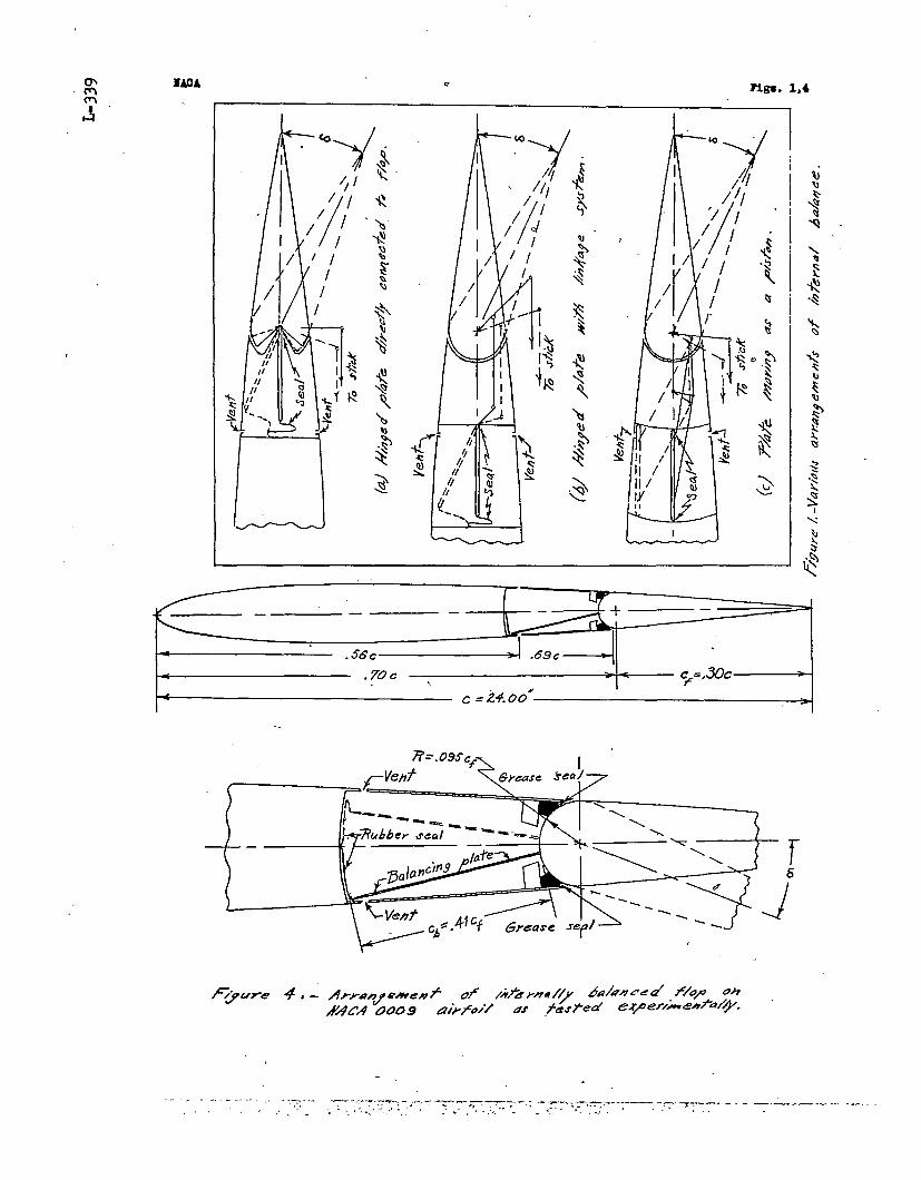
An internal balance consists esse~ti~lly-of a fla~plate enclosed in a sealed cha~ber uit~~n’’the airfoil(fig. 1). The plate is connected to the flap surface ei-ther directly as in figure l(a) or by a-linkage systern.+af3in figures l(b) and l(c). The free edges -of.ihe plateare sealed by a suitable means to the. iralls of the cham-ber in such a way that the static pressures at correspond-ing points on the upper and lower surfaceq ’of’the airf~il,admitted through vents, act on opposite. sides of the :dl’at~.The resulting force on the flat plate ‘causes a moment thattends to balance the aerodynamic hinge moment of the flap.
“ The hinge-moment characteristics of the f-lap can be con-trolled by varying the location of the.ve.nts and t.ha””sl’zeof the balancing plate. The calculatiori of the sectioncharacteristics of a flap with an internal balance is de-scri”hod in the fc)lloTJTinganalysis. ,““., ,‘<.:.,.[... ,
The distribution of pressure norms~:to the airfoilsurface has bean experimentally measured in two,-dirnensj.,onalflow for the MACA 0009 airfoil with plain flips” ‘(reference-s o1, 2, and 3). From a study of the pressure-di,st~i}ution
~~:.di”a-g~~s.Obtain’ed i~tit’h~”se“i~vesti”ga$i~”ri~,it “has ‘been ~x- ,perimentally determined that ~he variation of pressure atany point on the airfoil surfaoe is a linear function 0$both angle of attack and flap deflection. The-ran-go of”’linear variation, of course, is teymin~ted by. separationphenomena. ‘-”~’ 1 ““” ~“. “ “ ‘:’ ‘ #,
The ~atk of’chitige of-resulta~t pressure: coefficient~rith angle of attack Paa and with flap deflection P6a, :.-,. .,
is plotted as a function of chordwise position in figure 2for the NACA 0009 ~+rfp~> .Tq~$hA 0.3Qci a 0.50c; .e.nd an’0.80c plain flap with sealed gap at the flap nose. Be- .
..Cause .of segarati~n~phaqomena, the”variation of p :’~,j~tfi,~aa’;h~s,’the siofie .YaA. .only vitbip the ’li.mits’ a; a“~lo”>&-.. ,.and the variation of F“ with 82 has the slope ‘ ““%2only within 82 = ~lOO.
.“’. ,,, 7
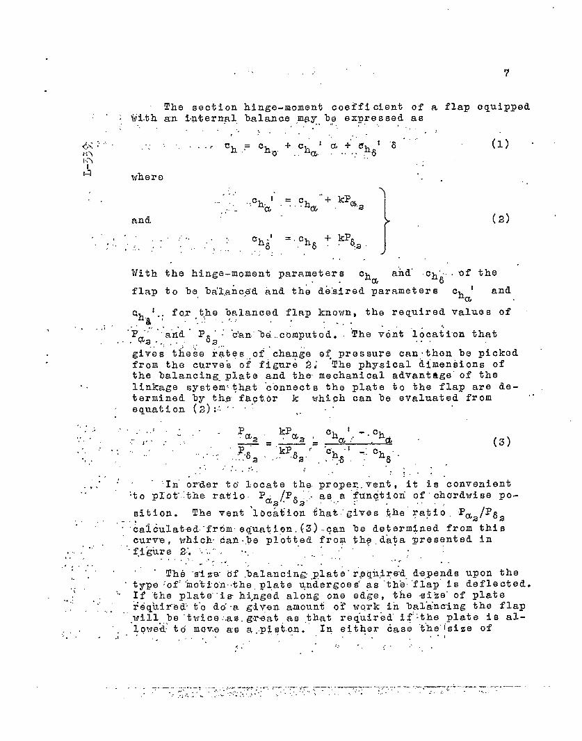
The section hinge-moment coefficient of a flap equipped,,...Iii.tham i’n%ernpl, balance ,m~y b,? expressed as
., . . .. . .. .. . .‘. .,. .. .. . . .,;r . .
. .,. . ..r ‘a+’&h t “6.-’”~h ,.=‘ho. ‘.cha. . . . .. ,. ,6(1) -
..
where . . .,
.. .
and
. ‘. ..
“+ kP )..ch,t .= .Chw... .,.a Q.a
,.’”-
).’ ,
? . .
.,. ,., ,.
. .
.
,,. ,, ,, ,;.. .. . .
. ,..,.! .
.,
. .’.,. ,
. .
(2),,
,.” ?.,.’ Ch .! =.c~ -t-kP6. :’.., .!.. . . . . . . . 6 6“J3’
.“::. J.,
l’fiththe hinge-moment parameters ch a“fid..ch....of theQ 6
flap to be bdl.anc~.d and the dbklred parameters ch 1 anda
Ch ‘.; fox,the balanced flap known, the required values Of8 ..:’” ~ ‘ ----
.$ ,: ,
~= .+~d “ F “ . “c’an.”%d..computo”da .62 ~‘The verit ‘loca~ion that
, . . .,.‘..), .> :---- . . .
gives these rates,,of ’chan~e o; pressure can. then he picked .from the curves of figUr8 2; The physical dimensions ofthe balancing-plate and the mechanical advantage” of thelinkage system$hat .c’onnects the plate to the flap are de-termined by th.~ faft,dr k which can be evaluated from “.equation (2):~ ‘“ ~ , “
.’ . .: - . . . 2.aa kPa ch t -.Ch.,,.J .- ..! a:
.~=“kP8a’= .~h “1
(3).. ... ,..,.. -:c~... . .... .2 . ... ~. .,6. 6
.. ,’,.. :“, .. .’.. .. :.-.. ..)
. . ‘In”order to locate the. prope~.vent, it is convenient.-toploti~the ral$ia Pti2~P8a. as:a ftin~tiori of”chcrrdwise po-.. . .sition. The vent ‘location fhat~gives ~he’ ratio. ~a2/F82
“.‘ ,,‘;‘&alculated-frdmeq uatiou .(3) .can be determined from this
curve , t~hich’dan.me plotted from thq.da~a presented in.,.,“ -.f,ikure 2:....... ....
.:,,.,. .,., ... . .......,,. ~.-. ... ..,... ‘>. . .. . ..,..,, , ,’.
The ‘size df .balancin~ .plate”r.pq~ir~ depends upon the.. .. type ‘of::mo%i.’o’n.the,pl,ate undergoes’ as ‘ths:”flap’is deflected?..\
.- If tke plate’i~ hi,nged along one ed~e, the -size.of plate.+.: .>.,.,., ,., r6quir’e& t-o old-a g.iyen amount of work in ba~.a:n~ing the flaP
.“.willile “twice:as.gr~at as ,that req.uirbd’ if’~the plate is al-Ig either case ‘t’he”~sizeof“. . lowed to move as a..p$?t+n. , . . ..,,..,.., . ., .,, .. . .
---- ~.-.,. .,.

8
plate required is ‘“d6te’imi”nedby tl+d “factdr. k. “After thevent locations have been determined, tihe-valties of Paa
and are know? and%2 k can he evaluated from equationz. ....
(2). Thus,-.
Cha 1 - cha kPm=k=.p ~. ., .= Pm2.“ ...,
(4)
For Q rectan~lar flat plate hinged at one ed~e, thenoment about the hi.q-gecaused” by’ a--uniformly distributedpressure is
pc~?y~:. . q’ y“k~cf%)fq “ “
.?-. .. .. ..”.. ..
This quantity.multi~lipd ?)y.the. ~echanical, advantagea6f/a8b of the connecting linkage is the baiancing moment
supplied to *he’ fla~. *Thb-”size of the balancing plate interms of the.,flap ch,ord is, therefore,. . . ..”. .. .
.:
.. . . .“,‘“’$=JFRO-’:(5)
.
.
..
If the vent on the upper surface is located at a dif-ferent airfoil K’ka-ti-o-p,-fromthat of the vent on the lowersurface , the in~ernal bal~ncq. wt~lc.ause the flap to havean initial hi.~~e-n-b~~nt;”co@f”tcient ch at an angle of
oattack and R flap deflection of O . In”this manner thoiritie”tinal”bblan-ce “call.”tie:-desi~ned“to supply the flap with
.,”. ‘&ri’i..tiit”idlf“lo”a~izingtendency. ‘ , , : “ ..... ..... t # . . .A~tier’ie:s-’of”ca~culatidtis ‘has ~een made: to illu”8trate
‘th0”possih!iX3ties of the “Ih’ternal.balance as a means of“re”gti”latin-g”thf3“bingo-nozieritlpar.amot.ers.-of.q coqtmo~. sur-faco . Tho resultant prossuro characteristiqa for the NAOA0009 airfoil in two-dimensional flow as presented in figure .
.,..,,2w~d~6’us6d” as~.the-”.baie.&.of %h& G%,kcu,latlon,s,and the re-
..”-. .9ult”$for tlio-0.30c and the 0.5.O.Cfl”a.pare given in figure‘;’-+.: ‘Tli6“appl.f%atfon o@;the zinalys.is already derived -is il-
lustrated ly the following [email protected] out fqr ome par-●
. . ‘; f-icul’arpo~rit ‘on:the”.curvesof fi5~re~3; Tlre,higge-~moment parameters ‘c. and Ch for the 0.30c plain flap
‘a 6

..
9
on the ITACA 0009 airfoil can be found by taking the momentabout the 0970c station of the areas under the curves ofP= fl(x/c) and Pa ,= f2(x/c) in figure 2. For theaz
m2
t.7 unbalanced flap, Ch = -0.00’75 and ch = -0.0130.I’.n a 8
h The vent locations and the length of the balancing platerequired to nako ch [ = O and ch 1 = O may be calcu-
a .6lated froa equation (3)
Pm~ o- (-0.0075)—=’62 0 - (-0.0130)
Figure 2 shov~s that Pa./P62 has
= 0.577
the calculated value of
C057’7 at s/c = 0.66. Tho vents should be located, there-fOre. at this station. The required length of the bal-ance-plate can be found fron tfie(4),
k=”- (-0.0075)
0.04?
Fron equation (5), fcr bb = %f
factor ‘k. Fron equation
= 0.160
and ~8f/~8~ = 1
cl—=Cf
2(0.160) (1) (1) = 0.56
.The section hi.n~e-monent characteristics for O.SOC
and 0,50c fla~s on the NLCA 0009 airfoil were coaputed,for 7arioqs arrangements of internal balance (fig. l(b)),to make t(+ = cha/2? 0, and -cha/ 2, The length of
-athe %alancing plate required to give the specified valuesof Cha’ and the resulting values of Ich6 are plotted
as functions of vent location in figure 3. The nochanicaladvantage of the systen is unity.
An inspection of figures 2 and 3 togother indicatesthat small valaes of Ch 1 nay ‘be obtained hy locating
8the vents near the flap hinge axis because in this regionthe rate of change of rewltant pressure with flap deflec-tion is large. The size of balancing plate required fora given Value of ch 1 will decrease, therefore, as the
6vent location approaches the hinge axis. Conversely, snail

—.. .. ... ... ~,= —.— .A “s.= +— . . ..— .-
10
values of ch 1 without much reduction in ch 1 may bea 8
obtained by locating the vents near the airfoil nose 3e-causo the size of %alancing plate required for a givenvaluo of ch t decreases as the vent location approaches
athe airfoil nose. Comparable auounts of %alance are ob-tained for the 0.30c and the 0.50c flap hy balancing platesof practically the sane size relative to the size of theflap and by practicall~ the sane location of the vent withrespect to the hings axis. For either flap, therefore, a~alancing plate approximately 0.50cf long with vents locat-
ed approximately 0.15cf ahead of the hinge axis is required
to reduce both ch 1 and ch 1 to zero.a a
Apparatu-s, Model, and Tests
.
Tests of a model wing with an internally balanced flaphave teen nade in the IULCA 4- %y 6-foot vertical tunnel inorder to chec’k the validity of the theoretical analysis.This tunnel, de.scri%ed in reference 4, has been nodified.for tests in two-di.nensional flow. A three-conponent lal-ance syste~. has been installed in the tunnel in order thatforce-test ~aasurenents of lift, drag, and pitching no-nent can be nade. Vhe hinge nonent of the flap was neas-ured by an electrical strain gage built into the model.
.
The 2-foot-chor& %y 4-foot-span nodel (fig. 4) WaSnade of la~inaiad aahogan~ to the ITACA 0009 prof~le (ta%leI). It was equiFped with an internality %alanced flap hav-ing a chord 30 parcent of the airfoil chort. The intern-al balance consistsd of a full-span flat plate o.41cf in
length and fastened rigidly to the flapt Tha plate vas “attacked to t~e flap iii such a way thzt w~on tho flap wasneutral th~ plate was def:ccted down 13 .5 . With” tlzisinsta~lation the flap could le deflected’ 24° positively.The edges of the plate VTere sealed to the walls of thebalancing chaaber by a rub%er sheet. At the 0.56c sta-
.
tion a series of holes 1/8 inch in dianeter (0.0052c).
.spaced spanwise 5/16 inch .(2$ rlian.) on centez’s were drilledthrough the upper and lower surfaces of the airfoil to servo , :as vents. For a part of the tests, the gap be+woon the air-foil and the nose of the” flap was sealed with a light grease.

11
For other tests, the vent location was moved hack near thabingo axis, to x/c = 0.69, ly renoving the grease thatfilled the gap and by sealing the original vents with
o\ scotch tape.
3ecause the ~odel completely spanned the tunnel, two-dimensional flow was approximated. The tests were Dade ata dynamic pressure of 15 pounds per square foot correspond-ing at standard sea-level conditions to an air velocity ofa%out 76 miles per hour and a test Reynolds num%er of1,430,000. Lift , drag, pitching moment, and flap hingemoment were measured for each flap deflection throughoutthe angle-of-attackorange from positive to negative stallof the airfoil in 2 increments ofoangle o: at~ack.o l?es~swere made at flap deflections 0% O , 1°, 2 , 5 , 10 ~ 15 ~20°, ~.nd 24° with the forward location of the vent. Theoutor 25 percent of the veuts at each end of the spanwere then sealed and tests wero made at flap deflectionsof 0° e,nd 10°. With the vent located near the hi~ge a~is,tests vore me,de at flap deflections of 0°, 5°, 10 , 15 ,20°, and 23.50..
Precision
The maximum error in the an le of attack or in flap5
setting appears to he about fO.2 . An experimentally de-termined tunnel correction has been applied only to lift.The hinge moments, therefore, are probably slightly higherthan would be obtained in free air. Because of an unknowntunnel correction, values of drag coefficient should notbe considered absolute; the relative values, hovevers aregenerally independent of tunnel effect.
Computed Characteristics of 171ap Tested
The balancing plate was rigidly fastened to the flapin such a way that the flap nose formed the rear wall ofthe balancing chamber (fig. 4). The predicted character-istics of figure 3, therefore, do not strictly apply forthis particular type of installation. Because the pres-sure in both sides of the balancing chamber acts uniform-ly on all walls of the chamber and because one wall ofthe chamber was the flap itself, the balancing moment mustbe calculated to include the moment of the force on thefla,p nose. The forvard edge Qf the lal.ancing plate wassealed to the forward wall of the chamber by a rubbersheet . For a proporly designed seal , therefore, half the

12
force on this seal may %e considered as %ei.ng transmittedto the flap as a balancing moment . For the type of install-ation tested, with the dimensions shown in figure 4, thebalancing moment is
P@R + cb/2)bbq = kpcfabfq
Therefove, because b~ = 3+
k=C3(R + ch/2) 2.945(0.680 + 2.945/2) = 0.122.,~=
Cf (’7.200)a
With the forward location of the vent, at X/C = 0.56, fromfigure 2
Paa = 0.062
P52 = 0.060
The hinge-moment parameters of the plain unbalanced flapare, from reference 5,
Ch = -0.0070a
Ch =8.
-0.0120
. . .These values are slightly less than those neaaured in tho ‘pressure-distribution investigation (reference.1) but, be-cause the ckord of the model of reference 5 was smaller(2 ft instead of 3 ft) possible tunnel effects are smallerthan for reference 1 and therefore these values are con-sidered more accurate.
From equation (2), the computed characteristics ofthe internally balaaced flap te~ted are
c~ ‘ = (-0.0070) + (0.122) (0.062)a
= 0.0006
Ch :,= (-0.0120) + (0.122) (0.060)a
= -0.0047
Sinilarly, with the vent loca%ed slightly forward of thehinge axis, at X/C = 0.69,
Paa = 0.041
P6 = 0.120a
.
..
c,....tnIn
A
.
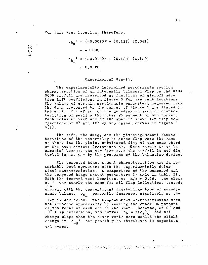
13
For this vent location, therefore,
Ch’= (-o.oo70j’+ (0.122) (0.041)a
= -0.0020
Ch ‘ = (-0.0120) -f- (0.122) (0.120)6
= 0.0026
Ex-perimental Results
The experimentally determined aerodynamic sectioncharacteristics of an internally balanced flap on the NACA0009 airfoil are presented as functions of airfotl sec-tion lift coefficient in figure 5 for two vent locations.The values of kertain aerodynamic parameters measured fronthe data presented by the curves of figure 5 are listed intalle II. The effect on the aerodynamic section charac-teristics of sealing the outer 25 percent of the forwardvent holes at each end of the span is shown for flap de-flections of 0° and 10° by the dashed curves in figure “5(a).
The lift, the drag, and the pitching-moment charac-teristics of the internally balanced flap were the sameas those for the plain, unbalanced flap of the sane chordon the sane airfoil (reference 5). This result is to beexpected because the air flow over the airfoil is not dis-turled in any way by the presence of the balancing device.
The computed hinge-noment characteristics are in re-markably good agreenent ?vith the experimentally deter-mined characteristics. A comparison of the measured andthe computed hinge-monent parameters is nade in table II.Vith the forward vent location, at X/C = 0.56, the slopech 1 was nearly the sane for all flap deflections tested;
awhereas vith the conventional inset-hinge type of aerody-namic b~lance. ch generally increases negatively as the
aflap is deflected. The hinge-nonent characteristics werenot affected appreciably ‘by sealing the outer 25 percentofothe vents at each end of the span. Because, at 0° and10 flap deflection, the curves ch = f(c& did not
change slope when the outer vents were sealed the slightchange in ch 1
6can probably bo attributed to experimen-
tal error.

____ J_” .. .,,-. -s. -.--,’.. ~ : -—”. +...- . . .
14
.The flap was overbalanced at deflections less than
10° when the vent was located near the hinge axis, at ‘X/G = 0e69, (fig. 5(3)). The-flap with this arrangementof internal balance will require the usQ of a leading,that is, unbalancing, tab in order to give satisfactorycharacteristics. The magnitude of overbalancing moment wasnot so great as that predicted from analytical consider-ations.
It should he noted that the experimental tests report-ed in this pager wero mado for steady-state attitudes ofthe model and no attcm~t was made to flnvestigato possiblelag effec~s or damping caused by the rate of change of theangie of attack or the flap deflection. The d,ete~minationof the optimum size of vent for minimum lag and for properdamping are subjects for future investigations.
THEORETICAL APl?LICA.Z!IONOF INTERNAL BALANCE
TO CONTROL SURZ’ACES OF FINITE SPAN .,
The spanwise as veil as the chordwise distribution of ‘ .resultant normal pressure over the surface of the wing b
must be known in order to calculate the vent locations andths size of balancing plate rea-uired to belance a controlsurface of finite span. Unfortunately; because the lifting-line theory assumes the induced downvmsh to be constantalong ths chord, the chordwise distribution of resultantpressure at a section of a wing in three-dimensional flow ‘cannot be accurately computed by the application of theo-retical aspect-ratio corrections based on the lifting-line theory to the chordvise distribution of resultantpressurs $(cr a ring in two-dimensional flow. Until the “lifting-surface theory provides an adequate method for thecomputation of chordwise distribution of resultant pressureat any section ~f a ving of finite aspect ratio or untilempirical correction factors are experimentally determinedfor the existing lifting-line theory, the pressure distri-bution and hence the hinge-moment characteristics of con-trol surfaces of finite span cannot be accurately estimat-
.ed from tvo-dimensione.l-flow data. A research program to
.,
correlate two- a“nd three-di’rnensional-flow aero~ynamiccharacteristics both theoretically and experimentally isbsing conducted by the NACA..
.,
. Section data, corrected according to the lifting-line

15
theory, can serve as a first approximation for the calcu-lation of the hinge-moment characteristics of a finite-span control surface with an internal balance. .&n internalbalance for a finite control surface may be designed fromthe pressure-distribution diagrams for two-dimensionalflow corrected in the marine: to be indicated in the discus-sion which follows, If experimental tests of such a bal-anced. surfaoe fail to give quite the desired hinge-mcmentcharactoristicst the Lirectioa and t.hs orfier of m2gI)iiUdeof modifications to the iaternal-ialancs Cesign can %e es-timated from the available pressure-distribution diagramseven though they are not exact.
In order to arrive at a first approximation to thevariation of resultant pressure coefficient with angle ofattack and flap deflection for a wing of finite aspectratio9 the span-load distribution should be computed.From the tablss presented in references 6 and 7, for wingsof various espect ratios and taper ratios, the sectionlift coefficient cl at any spanwise station can be com-puted in terms of the characteristics of the complete wing. “Thus, at any sectiou of a wing,
cl = c1 CL ‘3 + Ctbl CL8 63al a3 3
Therefore
The terms Ctal and c~b~are span-load distribution- ‘
factors and can be evaluated from references 6 and 7. .
If, in accordance with the lifting-line theory, the iinduced angle of attack at any section of a wing is as-sumed constant across the airfoil chord, the aspect-ratiocorrection to the variation of the resultant pressure dis-tribution with angle of attack is the distribution ofpressure caused by the induced angle of attack at the sec-tion in question. This correction is illustrated in figure ●
6. Thus
..=. — & :----- .. =&_____ ..— .-
..
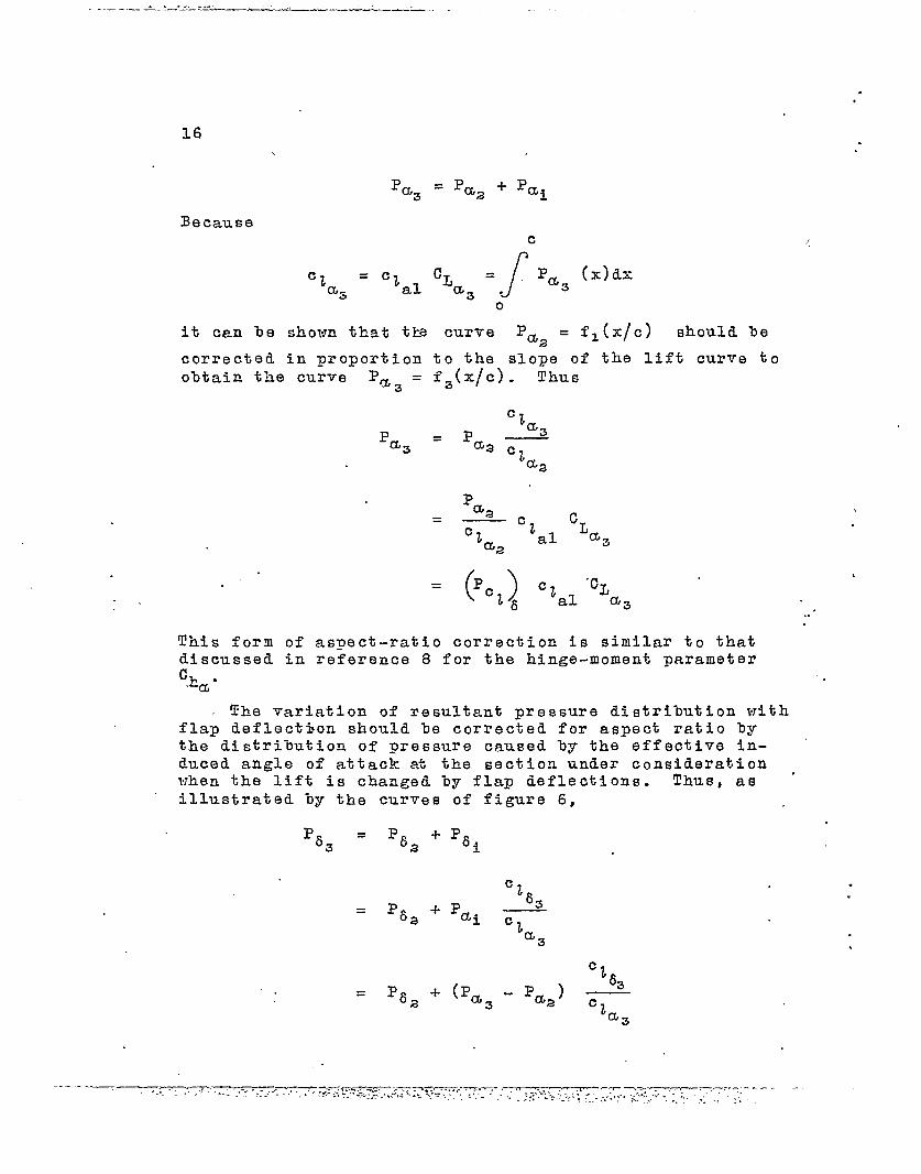
16
2 = %a+ Paia3
.
Becausec
c? = cl JCL =.Pas (x)dxas al a3 “
o
it cen be shown that tb curve I?aa = fl(x/c) should be
corrected in ~roportion to the slope of the lift curve toobtain the curve Pa= = f3(x/c). ‘l?hus
‘2P a3a=
=P—aa c
za~
.
.
..
This form of aspect-ratio correction is similar to thatdiscussed in referenae 8 for the hinge-moment parameter
%a “
The variation of resultant pressure distribution wi,thflap deflection should le corrected for aspeat ratio bythe distribution of pressure caused %y the effective in-duced angle of attack at the section under considerationwhen the lift is changed by flap deflations. Thus, as ‘illustrated by the curves of figure 6,
%3 = %2 + %i
..
.
.

1?
c.
The final expression for ‘6 ~ is similar to the’ aspect-
ratio correction for the hinge-moment parameter Cha (ref- .
erence 8). The resultant pressure distribution caused byflap deflection can be divided, therefore, into two partsas in figure 7. One part
(J‘8 = f5(x/c) is due to cam-
1
ber and, according to the lifting-line theory, is inde-pendent of aspect ratio.
()The other part Pcl CL = “
c% 83fe(x/c) is dependent on lift and must be corre%ted foraspect
()ratio in the manner indicated; Pc is theoret-
68ically independent of aspect ratio.
The curves Pa = f3(x/c) and %3 = f4(x/c) for z. 3
finite wing can be computed from the curves Paz = fl(x/o)
and %2 = f2(x/c) for the airfoil in tvo-dimensional flolt~.
Such computations, of course, are subject to all the limi-tations of the lifting-line theory. At best, therefore,the pressure distribution calculated by this method can offeronly a first approximation to the actual chordwise distribu-tion of resultant pressure at a section of a finite wing.For small aspect ratios, the effect of induced streamlinecurvature probally causes considerable discrepancy between
:;:;ct~::t}, .nd. %Jc,nd the comp ted distribution because the param-
cease to be independent of as-
pect ratio.
Once the curves Pm = f3(x/c) and %3 ‘= f4(x/c)3
have been determined at several spanvise locations, thecalculation of the characteristics of the internal balance .should be made i.n the same manner as has been discussed .for a model in two-dimensional flow. Thu-s it shoulQ bepossible to calculate the size of the balancing plate and

——.—.-. .—. J.L---- — —:..—- .—. Z . . .
.
18 .
the vent location that give any desired hinge-moment param-eters to a control surface of finite span.
As a part of the ITACA wind-tunnel investigation ofcontrol surfaces, experimental tests are scheduled to checkthe proposed method of making design calculations for aninternally. balanced control surface of finite span. Theexperimental tests of an internally balanced flap in two-dimensional flow have shown good agreement with the calcu-lations for a control surface of infinite aspect rktio. ,The tests in two-dimensional flow can serve, therefore, toindicate the direction in whicli the vent location shouldbe noved, on a control surface of finite span if the calcu-lated location should fail to give the desired hinge-moment charectoristics. The vent location should be movedtoward the leading edge of the airfoil to decrease ch I
e.and should be noved toward the flap hinge axis to decreasechl. The magnitude of the balancing moment may be varied
8 .%y altering the size of the balancing plate. This proce- .
duro does not change the ratio of the balancing momentproportional to the angle of attaok and the balancing mo- ,ment. proportional to the control-surface deflection.
PROPOS3D APPLICATION TO BALANCING TABS
One possible use of internal balance that is worthnoting is its application to balancing tabs. A full-spanbalancing tap 3.s a powerful device for reducing the hingemoments of a control surface provided that the tab can bedeflected as a function of angle of attack as well as offlap deflection. It iS theroforo proposod to provide acontrol surfaco with a full-span balancing tab aotuatedby an internal balance to govern the rate of tab deflec-tion with angle of attack and with flap defl~ction. If theflap is ~rovided with a moderate noso overhang, the amountof vork the tab must do to balance the flap is reduced anda tah of small chord that operates well within the linearrange may be used. The internal balance, because it has
.
only to augment the tab hinge moments, can be made smalland compact and most probably in the form of a piston andcylinder. The principal objection to an internal balance, 1
.
size, can therefore be largely overcome.
Calcul,atfons indicate that with the type of installa-tion descri%ed, the tab would float freely in such a manner

....
19
m1.3tp
la
that the hinge moments would %e reduced, the pllotts con-trol being attached directly to the flap. If the internal-ly b.alancod tab is arranged to float in such a way thatoh ‘ is positive, c~ is negative, and the pilot’s
‘d - %f
control effects a trim setting to the balancing tabs thesystem becomes the equivalent of a servocontrol systemthat has a tendency to float against the relative wind.
The explication of an internal balance to tabs becameapparent in the study of the characteristics of the inter-nal balance and it is mentioned In this paper only as apossible ~Lpplication of the device. The detailed charac-teristics of such a system are leyond the scope of thispaper and remain a subject for further investigation.
,(jo~JcLTJsIONs”
The theoretical analysis presented in this paper and “the experimental results of tests in two-dimensional flowof an internally balanced flap on an NACA 0009 airfoil in-dicate the following conclusions: ..,
1.. An ‘internal balance is a feasible and an aerody-namic~~~ desirable meins of controlling the magnitude and
the direction of the rate of change of flap hinge nonentwith angle of ‘attack and with flap deflection.
2. Section hinge-moment parameters calculated for aninternally balanced flap from experimentally determinedpressure-distribution .diagrans are in satisfactory agree-ment with pe,rameters measured experimentally on a modelin two-dimensional flow.
3.” E.xperi~ent indicates that because the internalbalance is entirely concealed within the airfpil contour,the lift, the drag, and the pitching-~omant characteris-tics of the control surfaco me in’no way affected by thepresence of the balancing surface.
4. Section dat”a, corrected for aspect ratio accord-ing to the lifting-line theory, can serve as a first ap-proximation for the calculation of the distrilmtion of re-sultant pressure and hence the hinge-noment characteris-tics for a finite-span control surface with an internalbalance.

. .. ..— -..
.
20
5. Analysis indicates that a full-span balancing tabactuated by an internal balance should prove to he a fea-sible method of reducing contsol forces.
Langley Menorial Aeronautical Laboratory,National Advisory Comnittee for Aeronautics,
Langley Field, Va.
1.
2.
3.
4.
5.
6.
‘?.
8.
hes, Milton 3., Jr., and Sears, Richard I.: Pressure-Distribution Investigation of an IT.A.C.A. 0009 Air-foil with a 30-i?ercent-Chord Plain Flap and ThreeTabs. T.N. no. 759, NACA, 1940.
Street, William G., and Aries, Milton B., Jr.: Pressure-Distribution Investigation of an N.A.C.A. 0009 Air-foil with a 50-Percent-Chord Plain I?lap and !l.!hree
.,
Tabs. Tn. 30. 734, ITACA, 1939.
Ames, Milto~ B., Jr., and Sears, Richard I.: Pressure- ,Distribution Investigation of an IT.A,C.A. 0009 Air-foil with an 80-Percent-Chord Plain E’lap and Three .Ta3s. T.IT. NO. 761, NACA, 1940.
I/enZinger, Carl J. , and Harris, Thomas A,: The VerticalWind Tunnel of the National Advisory Committee forAeronautics. Rep. No. 38?’, NACA, 1931.
Sears, Richard 1.: lJind-Tunnel Investigation of Control-Surface Characteristics. I - Effect of Gap on theAerodynamic Charatieristics of an NACA 0009 Airfoilwith a 30-Percent-Chord Plain Flap. I?ACA A.R.R.,June 1941.
Jacobs, Eastman 1?., and Rhode, R. V.: Airfoil SectionCharacteristics as Applied to the Prediction of AirTortes and Their Distrilnztion on Wings. Rep, No.631, NACA, 1938.
.L
Pearson, H. A.: Span Load Distribution for TaperedWings with Partial-Span Flaps. Rep. No. 585, NAOA,
.
1937..
Aries, Milton B., Jr., and Sears, Richard I.: Determi-nation of Control-Surface Characteristics from NACAPl~.in-Flap and Ta-o Data. Rep. No. 721, NACA, 1941s
.. .—-— —,T,,.,,, .,,_.,, .-,.. ..-. ...... . ::J..:...-.\’:- - -“-’>:,y: :.’.:..2:::.-:>;,:.... .;.C“”,:i.... .:..,,;..,. =.7 :-n’—“— —....... ,. ;+,.. .....3...;~.”..- ‘-.-’.-..,.-.,,,,..--.,. .-,... ,,.. .,”,“‘.

——— —-. ..— -— —.. . .
*
IAOA
\
UpperStation
Lswor8urr80e ●urrme
o o’1.25 1.42 -:.422.5 1.96 -1.96
2.67 -2.62j.5 3.15
p-3.15
15 :01p: :01
g M
c
w!
::? $:%
% 3?2.g
R
:$!
:: -1:97 .9095’ ;:8 3:%100 $.lO)“ (;.10)100
*
L- ~f Ebd3us: 0.89
TABU II
IRmuAxu BuAlFcQwoIEAoAmo9 A12FOIL
Vent looation
Parameter XU=O. S8 X/a = 0s69All vents Outer Computed Centinuoua Computodopen 25 peroent open Vent
vents sealed
()U1 00098 0.098 ------ 0.099 ------a6
(),
a6al
-.s0 -*!M ------ -.52 -----~
()%% ~
● 010 .010 - ------ .010 ------
&o)-.1s8 -0156 ----- -.158 -*----
Za
(%)1 -.0005 -.WOS o.- --- -00-00
~47a -.0060 “ -*OWT -.0047 * sO026a
%m-linw.
.
~ ,--.--;7:z-y - ~T:,,L ,~:~—.— . —— —---~ -—— .— —- -e.- ,T --, ~~ - .
.,,..- ,,. -.. : ‘.’ ; ‘, . ,: ’..:.- ‘“.” -’ -.-”“. .. ‘.’ “ - “-. ‘.. -----...
IMA c Hg8. 1,4
/1
,.
I— — — — n —--4.$sc~!ki “
.70C \ 1< CF=.30C
c =2+?00” *
R=.09scXY I
Rubber aeol -- ‘--—h
,
. . . . .-., _. . .. .. .. ._. _,,..,. .’,,. ., .’.

.4
‘.3
.2
r—..1-
1---------------- .1
1
i!
0,‘- , , , t 1 I , I , , I t I
d
-. . ..- . . . .
-- -----
1 1 I t
----
T.—---....--—-
.. -—.“4’-----I 1 I I I , 1 , 1 , t I ,
230C
L-339
u’” .0, ./, ,2/ ‘ ,3 .4” .5 .; .7 .& ,9 Lo-,
“+\
,,
*
2.- Balk of choge of ~e$ul%?hf
A!XCA -00(2 g
W/’fh Jea/ed
,
,
coefflhieh+ w).!.!dng/e of 07%2 CK
of “choAwAre /G’orjf/hh .
.

I.AaA,..
Hg.
.
—-L
Lo .— -
1~
u+ —— I—
— _—. —— ——
0 I
a
.
P
7CA’. .. ...
-— 0. aoa38
&T+F+--L
0i
-.0/ ~“---- –: ..:—_———.—————-.02 L
0 ./ .3 ,4{a)0.30zCfla~. Vefif Iocaf.
-.——
,/
___
Figure 3.- iffecf of Pe@’ /cu=u7&7. adCAE’ fo P jh&Paa//y &7/4mced
T—...—.—/\
.1
Lo
Slt$
1-_— ——-——-——
0
.03 I
I Ic&‘
/ l-l— — O. 6D69
.02—0000..... -.———- -.._
——— ——_ .0063
.CV
. /
$ 0 /
—-,0/
/,_-—-—
-,02~’ 1,,, , ../ .2 .9
--
/
/’-...
z!//-/
‘< -. i
?,
—
/’/k, !--’
// i-/ \j--_i $;.— 1—
1 I
7
I I I
.0 .3 Lo
.-.
—— -i -.–..
i
1-4’
-. .-— ---
*
1, .
!
.
—.. — —.
—-
11.
\ I-.
t ----
I
-+-
(b) 0.50 c f/ap. Venf /oca7%n, ~
Ffgure 3.- C’./.a’.d,
) i
I———A ——.4
-w—-—- --—I
I
.

.
fi~bi1 1 I 1 I 1 1 I I 1 I 1
+rd 5.-
,. .-,. .,.
&erol$aomc tiecz%7 CA@mC,fu.ris+ic# of MACAPo0,9pi2-f@Y JWWJ 0 C230 e
/aQced fhp. ,ti7*rno/!y
.0
●
----- -T -.. . .p.~— ~r ,. —,. .- —~-=...—.... ,:. , ,,, /....“. . . .,., ----- ., ’.. ,- :, ... 7-- —- ————— .—. —.. . .. ...- .. . . . . . . ..,. .’,. . . ... . .. . . ‘.. ,-. -.. .

*
N.4CA: Fig.5b$ # 1 ,
.U4
.
<{‘(
ia
I 1111111 llc4-LT.l/l.l●
..
/
. .
F/9vr.s 5, - Con C/udd.

—
. \2
—
YAaA.’ Fi@. 8,7I
.3 \ksns&a/-77!ow dMn3uiion (A s 3.6) !
—— Induced o!!8ir.&dion
.2
@o .
7/—-
0 ./ .2 .3 d~c
A@re 6.-Rate of c4ange of msul+anf prestwm coaWc.&ni WI% angk ofalfackvd w~h f7..po@f/ecil”ona~ Q {unc{ionof chom’vzse posi)%nfor“fwo-arw’+hzee-d/mmskno/ f/ow.NACA’OOOS a&fcoilwith a 030 cp/2/n flap wifi aem’tedgop.
P=3= ?&+ g,. q,-=q=*61.= ~a+gi +:.47 -._. ‘“-:”—-T”- ~
q*k I
—.--l-------I---- - ,..——- ...
%2
0 .~
.-0 ./
F/gure 7.-
----—---- ------ -- ...=...= ~ ~ —.-..,.-. ----.’— ~—.-. —.— .-,.. . . . . . . . . . . . .. >. ..,- .-
:. ~...”... ,,, ... ., ..’.. ,.’ . . . . . ..-” ‘
,..--- --~. .—-,-. — —-
Related Documents