©coseyfannitutti 2020 //// cftkb.com //// GitHub To build the MYSTERIUM through-hole kit you will need the following (not included): • Soldering iron and solder wire (kester 63/37 .031 inch leaded solder recommended) • Phillips head screwdriver • Flush side cutters (small) • Screw-in stabilizers (plate mounted stabilizers are not supported) o 3-4x 2u stabilizers (ANSI layout - 4x / ISO layout - 3x) o 1x 6.25u or 7u stabilizer (depending on bottom row layout) • 86-88x MX-style switches (plate mount or pcb mount) • Keycaps for MX switches • USB Type-C cable Recommended (not included): • No-clean flux paste (HIGHLY recommended to prevent bridging on USB pins) • Solder wick (to remove solder bridges if they occur) • Solder sucker (to remove solder from holes if a mistake is made and component needs to be reinserted)

Welcome message from author
This document is posted to help you gain knowledge. Please leave a comment to let me know what you think about it! Share it to your friends and learn new things together.
Transcript
©coseyfannitutti 2020 //// cftkb.com //// GitHub
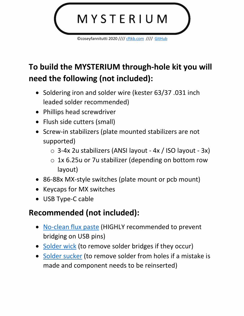
To build the MYSTERIUM through-hole kit you will
need the following (not included):
• Soldering iron and solder wire (kester 63/37 .031 inch
leaded solder recommended)
• Phillips head screwdriver
• Flush side cutters (small)
• Screw-in stabilizers (plate mounted stabilizers are not
supported)
o 3-4x 2u stabilizers (ANSI layout - 4x / ISO layout - 3x)
o 1x 6.25u or 7u stabilizer (depending on bottom row
layout)
• 86-88x MX-style switches (plate mount or pcb mount)
• Keycaps for MX switches
• USB Type-C cable
Recommended (not included):
• No-clean flux paste (HIGHLY recommended to prevent
bridging on USB pins)
• Solder wick (to remove solder bridges if they occur)
• Solder sucker (to remove solder from holes if a mistake is
made and component needs to be reinserted)
©coseyfannitutti 2020 //// cftkb.com //// GitHub
2
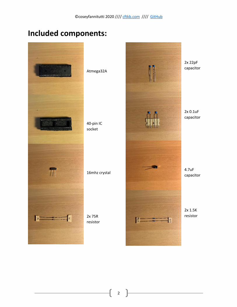
Included components:
Atmega32A
40-pin IC
socket
16mhz crystal
2x 75R
resistor
2x 22pF
capacitor
2x 0.1uF
capacitor
4.7uF
capacitor
2x 1.5K
resistor
©coseyfannitutti 2020 //// cftkb.com //// GitHub
3
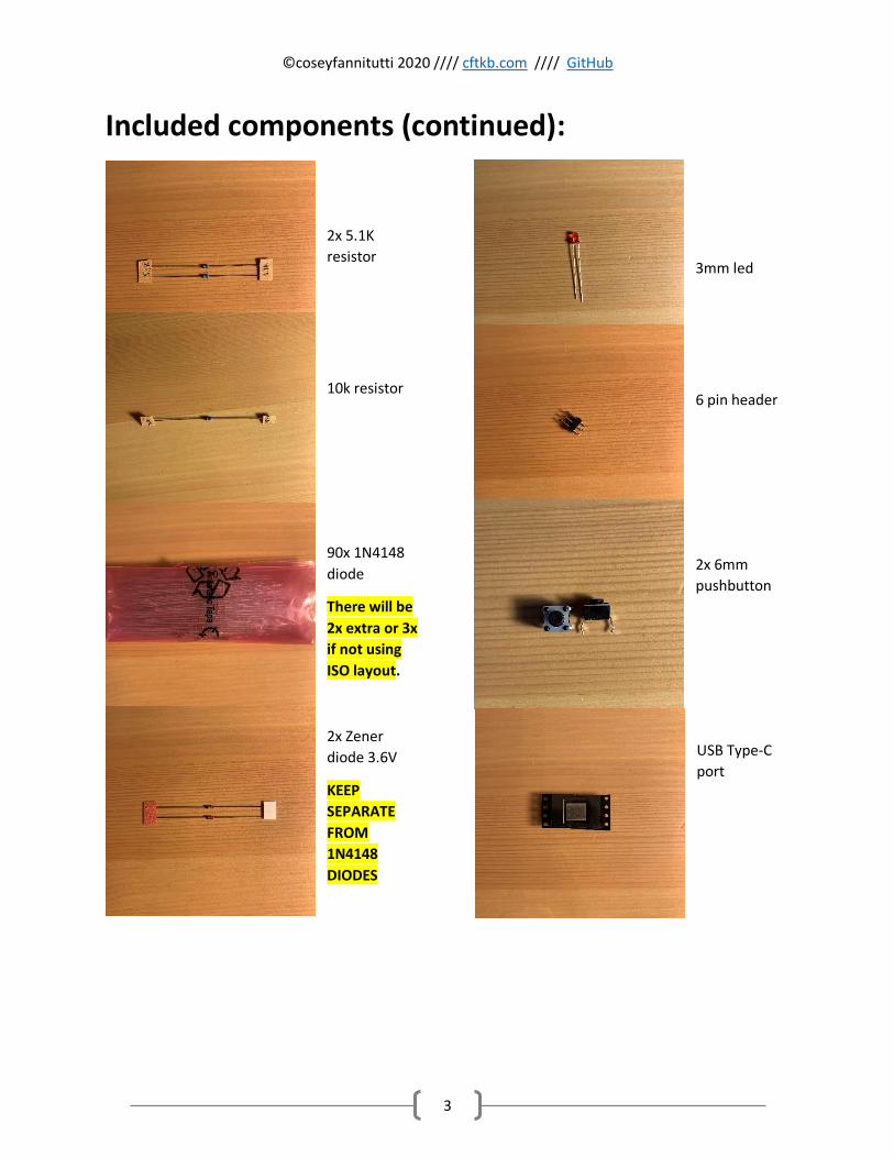
Included components (continued):
2x 5.1K
resistor
10k resistor
90x 1N4148
diode
There will be
2x extra or 3x
if not using
ISO layout.
2x Zener
diode 3.6V
KEEP
SEPARATE
FROM
1N4148
DIODES
3mm led
6 pin header
2x 6mm
pushbutton
USB Type-C
port
©coseyfannitutti 2020 //// cftkb.com //// GitHub
4
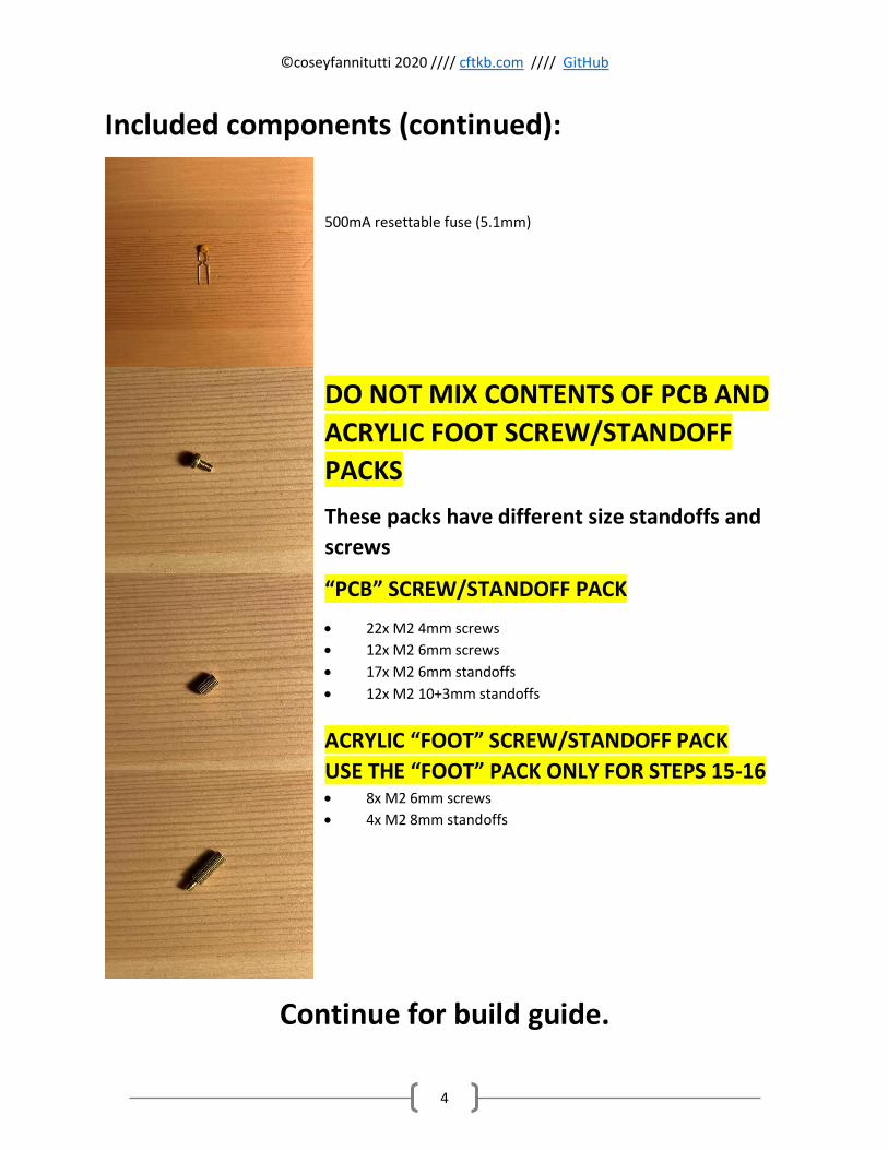
Included components (continued):
500mA resettable fuse (5.1mm)
DO NOT MIX CONTENTS OF PCB AND
ACRYLIC FOOT SCREW/STANDOFF
PACKS
These packs have different size standoffs and
screws
“PCB” SCREW/STANDOFF PACK
• 22x M2 4mm screws
• 12x M2 6mm screws
• 17x M2 6mm standoffs
• 12x M2 10+3mm standoffs
ACRYLIC “FOOT” SCREW/STANDOFF PACK
USE THE “FOOT” PACK ONLY FOR STEPS 15-16 • 8x M2 6mm screws
• 4x M2 8mm standoffs
Continue for build guide.
©coseyfannitutti 2020 //// cftkb.com //// GitHub
5
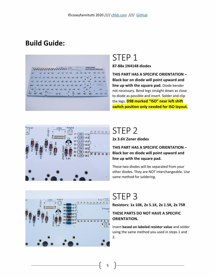
Build Guide:
STEP 1 87-88x 1N4148 diodes
THIS PART HAS A SPECIFIC ORIENTATION –
Black bar on diode will point upward and
line up with the square pad. Diode bender
not necessary. Bend legs straight down as close
to diode as possible and insert. Solder and clip
the legs. D98 marked “ISO” near left shift
switch position only needed for ISO layout.
STEP 2 2x 3.6V Zener diodes
THIS PART HAS A SPECIFIC ORIENTATION –
Black bar on diode will point upward and
line up with the square pad.
These two diodes will be separated from your
other diodes. They are NOT interchangeable. Use
same method for soldering.
STEP 3 Resistors: 1x 10K, 2x 5.1K, 2x 1.5K, 2x 75R
THESE PARTS DO NOT HAVE A SPECIFIC
ORIENTATION.
Insert based on labeled resistor value and solder
using the same method you used in steps 1 and
2.
©coseyfannitutti 2020 //// cftkb.com //// GitHub
6
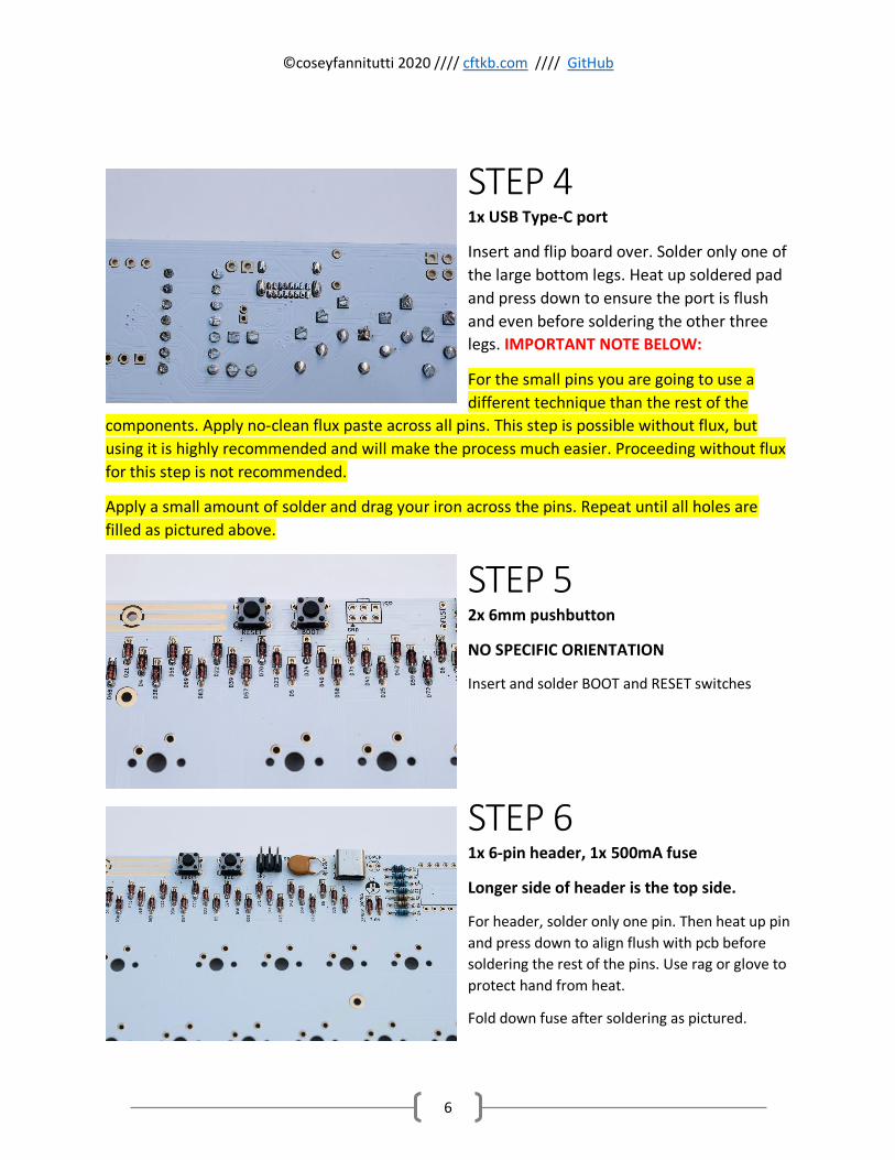
STEP 4 1x USB Type-C port
Insert and flip board over. Solder only one of
the large bottom legs. Heat up soldered pad
and press down to ensure the port is flush
and even before soldering the other three
legs. IMPORTANT NOTE BELOW:
For the small pins you are going to use a
different technique than the rest of the
components. Apply no-clean flux paste across all pins. This step is possible without flux, but
using it is highly recommended and will make the process much easier. Proceeding without flux
for this step is not recommended.
Apply a small amount of solder and drag your iron across the pins. Repeat until all holes are
filled as pictured above.
STEP 5
2x 6mm pushbutton
NO SPECIFIC ORIENTATION
Insert and solder BOOT and RESET switches
STEP 6 1x 6-pin header, 1x 500mA fuse
Longer side of header is the top side.
For header, solder only one pin. Then heat up pin
and press down to align flush with pcb before
soldering the rest of the pins. Use rag or glove to
protect hand from heat.
Fold down fuse after soldering as pictured.
©coseyfannitutti 2020 //// cftkb.com //// GitHub
7
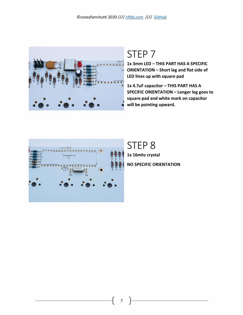
STEP 7 1x 3mm LED – THIS PART HAS A SPECIFIC
ORIENTATION – Short leg and flat side of
LED lines up with square pad
1x 4.7uF capacitor – THIS PART HAS A
SPECIFIC ORIENTATION – Longer leg goes to
square pad and white mark on capacitor
will be pointing upward.
STEP 8 1x 16mhz crystal
NO SPECIFIC ORIENTATION
©coseyfannitutti 2020 //// cftkb.com //// GitHub
8
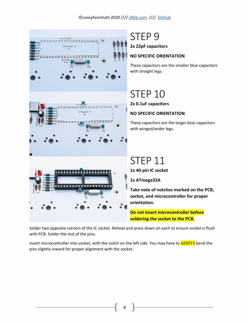
STEP 9 2x 22pF capacitors
NO SPECIFIC ORIENTATION
These capacitors are the smaller blue capacitors
with straight legs.
STEP 10 2x 0.1uF capacitors
NO SPECIFIC ORIENTATION
These capacitors are the larger blue capacitors
with winged/wider legs.
STEP 11 1x 40-pin IC socket
1x ATmega32A
Take note of notches marked on the PCB,
socket, and microcontroller for proper
orientation.
Do not insert microcontroller before
soldering the socket to the PCB.
Solder two opposite corners of the IC socket. Reheat and press down on each to ensure socket is flush
with PCB. Solder the rest of the pins.
Insert microcontroller into socket, with the notch on the left side. You may have to GENTLY bend the
pins slightly inward for proper alignment with the socket.
©coseyfannitutti 2020 //// cftkb.com //// GitHub
9
It is highly recommended before proceeding to test your
PCB for functionality at this point before soldering your
switches.
You may use a key tester such as the one included with
VIA to test your keys by shorting the switch pads with
tweezers or a bent diode leg salvaged from this build.
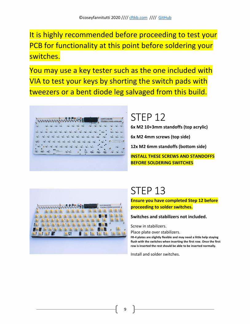
STEP 12 6x M2 10+3mm standoffs (top acrylic)
6x M2 4mm screws (top side)
12x M2 6mm standoffs (bottom side)
INSTALL THESE SCREWS AND STANDOFFS
BEFORE SOLDERING SWITCHES
STEP 13 Ensure you have completed Step 12 before
proceeding to solder switches.
Switches and stabilizers not included.
Screw in stabilizers.
Place plate over stabilizers. FR-4 plates are slightly flexible and may need a little help staying
flush with the switches when inserting the first row. Once the first
row is inserted the rest should be able to be inserted normally.
Install and solder switches.
©coseyfannitutti 2020 //// cftkb.com //// GitHub
10
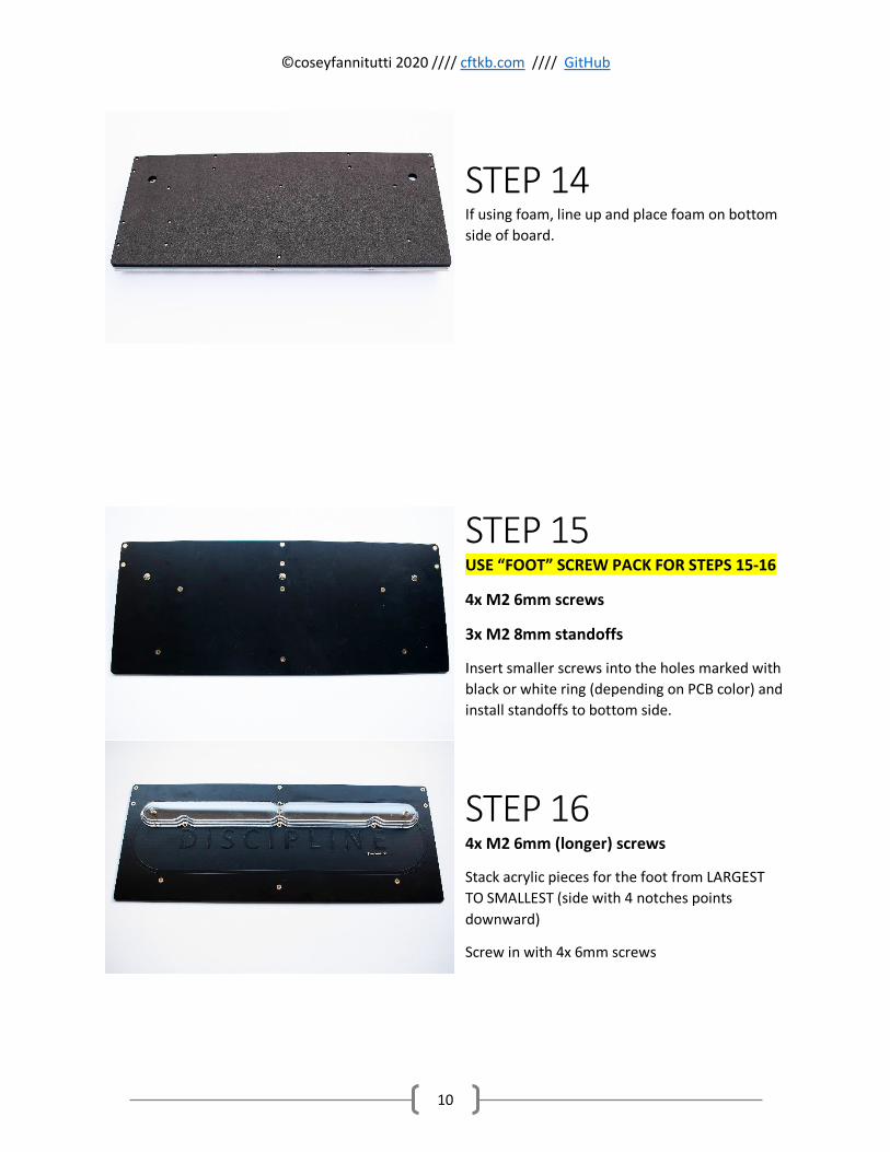
STEP 14 If using foam, line up and place foam on bottom
side of board.
STEP 15 USE “FOOT” SCREW PACK FOR STEPS 15-16
4x M2 6mm screws
3x M2 8mm standoffs
Insert smaller screws into the holes marked with
black or white ring (depending on PCB color) and
install standoffs to bottom side.
STEP 16 4x M2 6mm (longer) screws
Stack acrylic pieces for the foot from LARGEST
TO SMALLEST (side with 4 notches points
downward)
Screw in with 4x 6mm screws
©coseyfannitutti 2020 //// cftkb.com //// GitHub
11
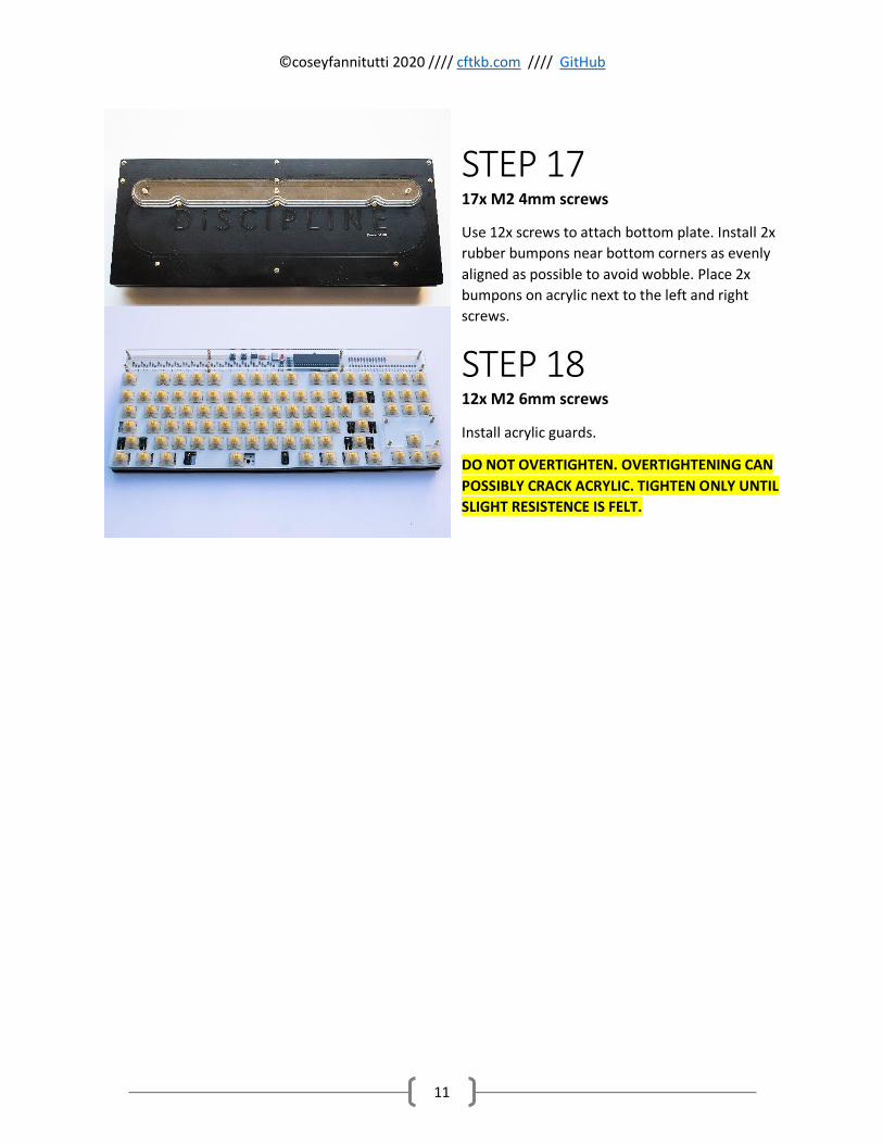
STEP 17 17x M2 4mm screws
Use 12x screws to attach bottom plate. Install 2x
rubber bumpons near bottom corners as evenly
aligned as possible to avoid wobble. Place 2x
bumpons on acrylic next to the left and right
screws.
STEP 18 12x M2 6mm screws
Install acrylic guards.
DO NOT OVERTIGHTEN. OVERTIGHTENING CAN
POSSIBLY CRACK ACRYLIC. TIGHTEN ONLY UNTIL
SLIGHT RESISTENCE IS FELT.
©coseyfannitutti 2020 //// cftkb.com //// GitHub
12
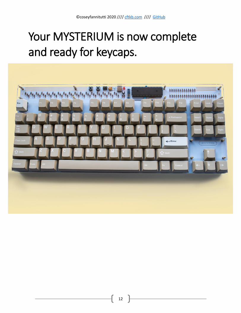
Your MYSTERIUM is now complete and ready for keycaps.
Related Documents