Camera Hardware Manual

Welcome message from author
This document is posted to help you gain knowledge. Please leave a comment to let me know what you think about it! Share it to your friends and learn new things together.
Transcript

Camera Hardware Manual

Page 2 of 22
Disclaimer
Copyright © 2009-2010 by MYLAPS SPORTS TIMING (previously AMB i.t. B.V.)
This publication is to be used for the Finish Camera. This publication has been written with great care.
However, the manufacturer cannot be held responsible, either for any errors occurring in the publication or for their consequences. Information in this document is subject to change without
notice.
All rights reserved. No part of this publication may be reproduced, stored in a retrieval system, or
transmitted, in any form or by any means, electronic, mechanical, photocopying, recording, or otherwise, without the prior written consent of the publisher.
Printed in the Netherlands
Manual version: 1.0
MYLAPS SPORTS TIMING Zuiderhoutlaan 4
2012 PJ Haarlem The Netherlands
Phone: +31 23 529 1893
Fax: +31 23 529 0156
Email: [email protected] Web: www.mylaps.com
Page 3 of 22
Table of Contents
CAMERA HARDWARE MANUAL ................................................................................................................... 1
DISCLAIMER ....................................................................................................................................................... 2
INTRODUCTION ................................................................................................................................................. 4
ABOUT THIS DOCUMENT ...................................................................................................................................... 4
BASIC CONCEPT................................................................................................................................................. 5
SYSTEM OVERVIEW .............................................................................................................................................. 6
FINISH CAMERA INSTALLATION ................................................................................................................. 7
CONNECTIONS ..................................................................................................................................................... 7 NETWORK SETTINGS ............................................................................................................................................ 8 NETWORK SETTINGS FOR AUTOMATIC CONFIGURATION ...................................................................................... 8 NETWORK SETTINGS FOR STATIC CONFIGURATIONS ............................................................................................ 8 TRACK SIDE PLACEMENT ..................................................................................................................................... 9
OPERATING THE FINISH CAMERA ............................................................................................................ 12
CAMERA STATUS LED ....................................................................................................................................... 12 FRONT PANEL .................................................................................................................................................... 12 POWERING UP THE FINISH CAMERA ................................................................................................................... 13 POWERING DOWN THE FINISH CAMERA ............................................................................................................. 13
CONFIGURATION ............................................................................................................................................ 14
NETWORK SETTINGS .......................................................................................................................................... 14 STATIC NETWORK SETUP ................................................................................................................................... 15 AUTOMATIC CONFIGURATION ........................................................................................................................... 15 SYNC UNIT SERIALNUMBER .............................................................................................................................. 16 UPDATE FIRMWARE ........................................................................................................................................... 16
DIAGNOSTICS AND STATUS ......................................................................................................................... 17
MAIN INFORMATION SCREEN ............................................................................................................................. 17 VERSION AND STATUS SCREEN .......................................................................................................................... 18 SYSTEM INFORMATION ...................................................................................................................................... 18 NETWORK INFORMATION ................................................................................................................................... 19 CAMERA LINK STATUS ...................................................................................................................................... 19
TECHNICAL SPECIFICATIONS .................................................................................................................... 21
CAMERA DECODER SPECIFICATIONS ................................................................................................................. 21 CAMERA SPECIFICATIONS (2K LINES) ................................................................................................................ 21 CAMERA SPECIFICATIONS (10K LINES) .............................................................................................................. 21 STANDARDS CONFORMITY ................................................................................................................................. 22

Introduction
About this document This document explains the installation and operation of the Finish
Camera hardware.
Page 5 of 22
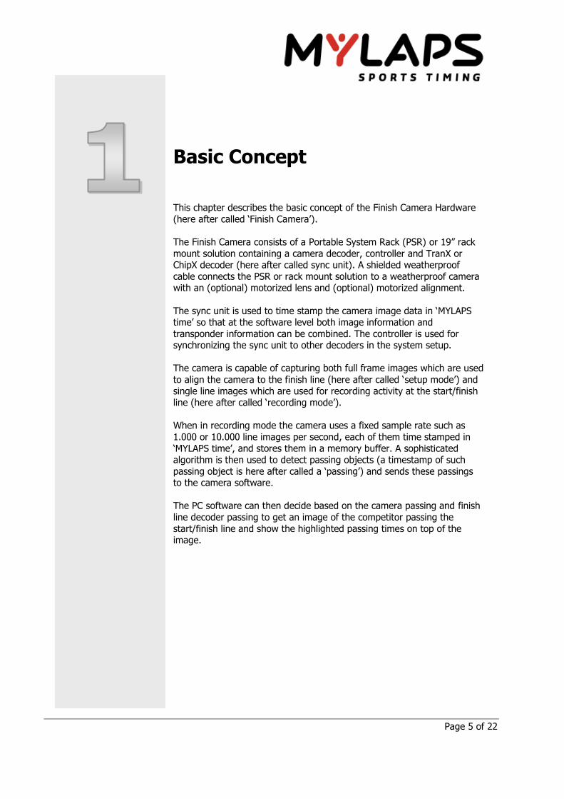
Basic Concept
This chapter describes the basic concept of the Finish Camera Hardware
(here after called ‘Finish Camera’).
The Finish Camera consists of a Portable System Rack (PSR) or 19” rack
mount solution containing a camera decoder, controller and TranX or ChipX decoder (here after called sync unit). A shielded weatherproof
cable connects the PSR or rack mount solution to a weatherproof camera with an (optional) motorized lens and (optional) motorized alignment.
The sync unit is used to time stamp the camera image data in ‘MYLAPS time’ so that at the software level both image information and
transponder information can be combined. The controller is used for synchronizing the sync unit to other decoders in the system setup.
The camera is capable of capturing both full frame images which are used
to align the camera to the finish line (here after called ‘setup mode’) and
single line images which are used for recording activity at the start/finish line (here after called ‘recording mode’).
When in recording mode the camera uses a fixed sample rate such as
1.000 or 10.000 line images per second, each of them time stamped in
‘MYLAPS time’, and stores them in a memory buffer. A sophisticated algorithm is then used to detect passing objects (a timestamp of such
passing object is here after called a ‘passing’) and sends these passings to the camera software.
The PC software can then decide based on the camera passing and finish
line decoder passing to get an image of the competitor passing the
start/finish line and show the highlighted passing times on top of the image.
Page 6 of 22
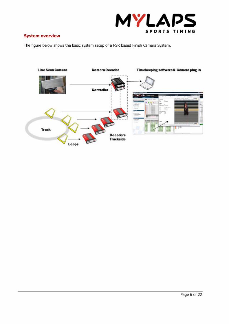
System overview
The figure below shows the basic system setup of a PSR based Finish Camera System.

Page 7 of 22
Finish Camera installation
Connections
Figure 1 PatchPanel
Connect the supplied network cable between the Camera
connection on the patch panel and the Cam connection on the
camera. Make sure this is a direct connection and it is not connected through a network switch or hub. The connection is
pictured in RED.
Connect a network cable between the PC connection and your
PC. This does not have to be a direct connection and can be routed through a network switch or hub. The connection is
pictured in grey. Connect the power cable. Use the supplied Y-cable to make the
connection. Both connections should be powered.
Page 8 of 22
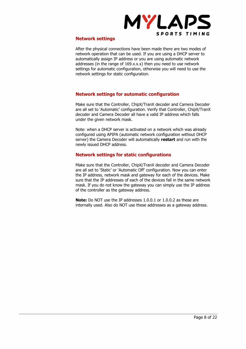
Network settings
After the physical connections have been made there are two modes of network operation that can be used. If you are using a DHCP server to
automatically assign IP address or you are using automatic network addresses (in the range of 169.x.x.x) then you need to use network
settings for automatic configuration, otherwise you will need to use the
network settings for static configuration.
Network settings for automatic configuration
Make sure that the Controller, ChipX/TranX decoder and Camera Decoder
are all set to ‘Automatic’ configuration. Verify that Controller, ChipX/TranX decoder and Camera Decoder all have a valid IP address which falls
under the given network mask.
Note: when a DHCP server is activated on a network which was already
configured using APIPA (automatic network configuration without DHCP server) the Camera Decoder will automatically restart and run with the
newly issued DHCP address.
Network settings for static configurations
Make sure that the Controller, ChipX/TranX decoder and Camera Decoder
are all set to ‘Static’ or ‘Automatic Off’ configuration. Now you can enter the IP address, network mask and gateway for each of the devices. Make
sure that the IP addresses of each of the devices fall in the same network
mask. If you do not know the gateway you can simply use the IP address of the controller as the gateway address.
Note: Do NOT use the IP addresses 1.0.0.1 or 1.0.0.2 as these are
internally used. Also do NOT use these addresses as a gateway address.

Page 9 of 22
Example configuration for a standalone network with a Finish Camera and
single PC using local network 192.168.x.x:
PC network settings
o IP address 192.168.1.1 o Network mask 255.255.255.0
o Gateway: 192.168.1.1
Controller network settings
o IP address 192.168.1.2 o Network mask 255.255.255.0
o Gateway: 192.168.1.1 ChipX/TranX network settings
o IP address 192.168.1.3
o Network mask 255.255.255.0
o Gateway: 192.168.1.1 Camera Decoder network settings
o IP address 192.168.1.4
o Network mask 255.255.255.0 o Gateway: 192.168.1.1
Track side placement
The camera comes with a mounting head that allows the camera to
rotate around 3 axis. It can pan, tilt and roll.
Tilt
Pan
Rolll
However the most important thing about camera placement is to make
sure that it is aligned correctly with the finish line.
Pan, tilt and roll will not help to correctly line out a camera that has been
placed incorrectly besides the track.

Page 10 of 22
As can be seen in the upper picture when the camera is placed not on the
finish line but slightly next to it then the timing results for competitors in
the different lanes will have an offset in the results. In the above case the competitor in the most far away lane will have to travel a longer distance
to cross the photo finish line than the competitor in the closest lane.
To check that the camera is lined up with the finish line you can connect
a plumb line to the mounted camera and then check if the plumb line hits the ground at the finish line.
After the camera is lined up correctly to the finish line make sure that the
2d camera plane is at a 90 degree angle to the finish line. You can rotate (roll) the camera to align it correctly.
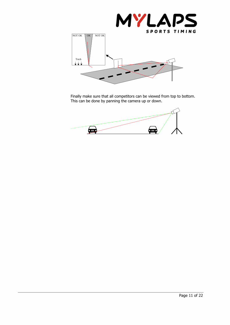
Page 11 of 22
OK
Track
NOT OK NOT OK
Finally make sure that all competitors can be viewed from top to bottom.
This can be done by panning the camera up or down.

Page 12 of 22
Operating the Finish Camera
Camera status LED
The camera is equipped with a dual color status LED indicating the current camera operating mode.
LED blinking green – the camera is attempting to get a
connection with the camera decoder LED blinking red – the camera is updating its firmware.
LED solid green – the camera is in setup mode
LED solid red at power on – the camera firmware is corrupt. This
can be corrected by a firmware update
LED solid red during recording – the camera is in recording mode
Front panel
The Camera Decoder is equipped with a front panel housing an OLED
display, an USB slot, 3 status LEDs and a rotary pushbutton.
1. The OLED display is used to show status/diagnostics
information and to review and change settings.
2. The rotary pushbutton is used to navigate the menu options and to select/confirm an option.
3. The USB slot is used for firmware updates. 4. The PWR led is on when the Camera Decoder has power.
5. The SSD led is on when the Camera Decoder is reading or
writing to the solid state device. 6. The POE led is on when the Camera is receiving power from the
Camera Decoder.

Page 13 of 22
Powering up the Finish Camera
The Finish Camera is configured to automatically power up all hardware when the power plug is inserted. If the power plug is already inserted
press and HOLD the rotary pushbutton on the Camera Decoder for 5 seconds. The Camera Decoder will now show a ‘starting camera’ logo
which will change to the main diagnostics screen when the Camera
Decoder startup sequence has been completed.
Powering down the Finish Camera
Press and HOLD the rotary pushbutton on the Camera Decoder for 5
seconds. The Camera Decoder will now show a ‘shutdown’ logo which will be displayed until the power down sequence is completed.
For a complete power down the power plug should be unplugged.

Page 14 of 22
Configuration
To go to the menu screens, rotate the rotary pushbutton clockwise. When on the menu screen rotate clockwise or counterclockwise to select an
option and push the rotary pushbutton to confirm the selection.
The main menu screen:
The following menus and options are available:
Network Settings
o Static Network Setup Ip Address
Netmask
Gateway o Automatic Config On/Off
o << (back to main menu screen) Sync Unit SerialNumber
Firmware Update
<< (back to main information screen)
Network Settings
There are two main modes available for the network link between the camera decoder and the sync unit and camera software on the PC. It can
be automatic which means that an IP address should be assigned either by a DHCP server or by APIPA, or static meaning that the IP
configuration as set in the Static Network Setup should be used for the
network configuration.

Page 15 of 22
Static Network Setup
The network settings that can be configured are IP address, net mask
and gateway. Rotate the rotary pushbutton clockwise and/or counter clockwise to scroll through the settings. To edit a setting push the rotary
pushbutton once to edit a digit then rotate clockwise and/or counter
clockwise to select the digit and finally push the rotary button again to confirm the selection.
To apply the settings push the rotary pushbutton when highlighting ‘apply’. To cancel the settings push the rotary pushbutton when
highlighting ‘cancel’.
If the networking mode is set to ‘Automatic Config Off’ the network
configuration change will take effect immediately. If the networking mode is set to ‘Automatic Config On’ then the networking configuration will take
effect when the networking mode is switched.
Only the most elementary error checking is done for illegal network
configurations. If the network setting is illegal then the camera decoder will simply not show up in the camera software.
Caution: the camera decoder needs to be restarted when changing
network configuration. Any connection to the camera decoder will be lost
and any recording will be stopped.
Caution: the IP addresses 1.0.0.1 and 1.0.0.2 are used for camera link communication between camera decoder and camera. Do NOT use these
IP addresses in the static network setup.
Automatic Configuration
Automatic configuration allows switching between obtaining the network
settings from a DHCP server (or APIPA) and using the static network setup for network configuration.
Caution: the camera decoder needs to be restarted when changing
network configuration. Any connection to the camera decoder will be lost and any recording will be stopped.
Note: when a DHCP server is activated on a network which was already configured using APIPA (automatic network configuration without DHCP
server) the Camera Decoder will automatically restart and run with the newly issued DHCP address.

Page 16 of 22
Sync Unit SerialNumber
The sync unit serial number is the serial number of the ChipX or TranX
decoder that is used for time stamping the line images. Please see the ChipX or TranX decoder manual on how to obtain the
serial number from the decoder. If the serial number is incorrect recording is not possible. Please check the ‘Version and Status’ screen to
verify that the connection to the decoder has been established. Caution: the camera decoder needs to be restarted when changing the
sync unit serial number. Any connection to the camera decoder will be
lost and any recording will be stopped.
Update Firmware
The camera decoder allows firmware updates through USB drives. Please check the information that comes with the firmware update on details of
how to prepare the USB drive. To update the firmware insert the USB drive into the USB slot and then
select ‘Update’. The message ‘Update in progress…’ will be displayed
while the camera decoder is copying the updated firmware from the USB drive to the internal storage. When the data copy is completed the
message ‘Update done, rebooting….’ will be displayed. The USB drive can be removed from the USB slot at this point. Please allow up to 5
minutes for the camera to be restarted.
To verify that the firmware has been updated check the version numbers
on the ‘Version and Status’ screen.
Caution: Do not power off the camera decoder during the ‘Update in progress…’ message or the camera decoder may fail to start up due to
firmware data corruption.

Page 17 of 22
Diagnostics and status
To cycle through the status and diagnostics screens, repeatedly push the rotary pushbutton when on any of the status and diagnostics screens.
The information on the diagnostics screens is normally only used for troubleshooting. There is no need to monitor this information for normal
operation of the camera.
The following screens are available:
Main information screen
Version and Status screen
System Information screen
Network Information screen
Camera link Status screen
Main information screen
The first line shows the status of the camera:
Camera: Disconnected
Camera: Setup Mode
Camera: Recording Mode.
The first character of the line switches between -, + and * symbols to show that the decoder is still alive.
The third line shows the current IP address used by the Camera Decoder.
The fourth line shows how the current IP address was obtained. Either by using the static settings or by obtaining an IP address the automatic
way by DHCP or APIPA. An APIPA address is any IP address in the range of 169.254.0.1 – 169.254.255.254 which is assigned if no DHCP address
was assigned.
Page 18 of 22
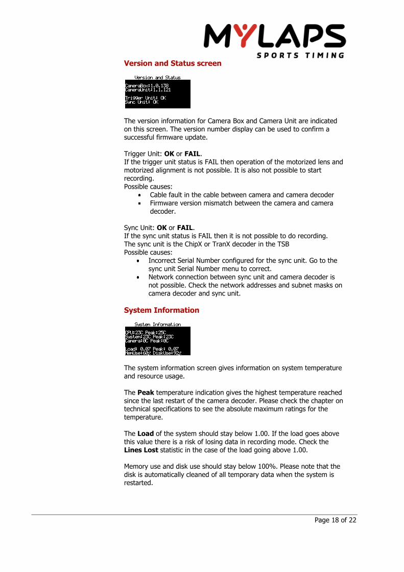
Version and Status screen
The version information for Camera Box and Camera Unit are indicated
on this screen. The version number display can be used to confirm a successful firmware update.
Trigger Unit: OK or FAIL. If the trigger unit status is FAIL then operation of the motorized lens and
motorized alignment is not possible. It is also not possible to start recording.
Possible causes:
Cable fault in the cable between camera and camera decoder
Firmware version mismatch between the camera and camera
decoder.
Sync Unit: OK or FAIL. If the sync unit status is FAIL then it is not possible to do recording.
The sync unit is the ChipX or TranX decoder in the TSB
Possible causes: Incorrect Serial Number configured for the sync unit. Go to the
sync unit Serial Number menu to correct.
Network connection between sync unit and camera decoder is
not possible. Check the network addresses and subnet masks on camera decoder and sync unit.
System Information
The system information screen gives information on system temperature
and resource usage.
The Peak temperature indication gives the highest temperature reached
since the last restart of the camera decoder. Please check the chapter on technical specifications to see the absolute maximum ratings for the
temperature.
The Load of the system should stay below 1.00. If the load goes above
this value there is a risk of losing data in recording mode. Check the Lines Lost statistic in the case of the load going above 1.00.
Memory use and disk use should stay below 100%. Please note that the
disk is automatically cleaned of all temporary data when the system is restarted.

Page 19 of 22
Network Information
The network information screen gives information the network interface
that is used to communicate between the camera decoder and the camera software, sync unit and the rest of the PC network.
IP and how it was obtained is the same information as on the main information screen.
Link:
Down means there is no network connection. No cable is
plugged in or the cable is damaged
100M means the network link runs at 100Mbit.
1000M means the network link runs at gigabit speed.
Rx and Tx give the average network utilization by the camera decoder.
When the link is connected at 100Mbit the maximum effective bandwidth can be as low as 8 MBps so be careful not to overload the network link.
Note: The controller contains a 100Mbit switch, so in configurations where the Camera Decoder is connected through the controller the
maximum speed on the network link is 100Mbit.
Camera Link Status
The camera link status screen gives information about the interface that is used to communicate between the camera decoder and the camera.
Link:
Down means there is no network connection. No cable is
plugged in or the cable is damaged.
100M means the link runs at 100Mbit. Cable is damaged or
not plugged in correctly. 1000M means the link runs at the correct speed.
Rx and Tx give the average network utilization between the camera and camera decoder.
Errors are the amount of network packets that were rejected due to data
corruption. This statistic is reset when the camera decoder is restarted.
Total gives the total amount of network packets transferred so far. This statistic is reset when the camera decoder is restarted.
Lines Lost gives the amount of recorded lines that were lost due to network packet errors. This statistic is reset at the start of each
recording.

Page 20 of 22
In the best case there should not be any error during operation of the
camera decoder. However with long cables which are routed next to sources of electromagnetic noise such as power lines it is possible that
the occasional error occurs (such as 1 error packet per 1 million total packets). The camera decoder uses error detection and data
resend/recovery techniques to avoid losing recording data due to network
problems. If lines are lost and there are no error packets, it could be due to excessive system load. Check the system information screen for load
information.

Page 21 of 22
Technical Specifications
Camera Decoder Specifications
Operating Temp. 0 to 60 degrees Celsius
Humidity 0 to 80% relative
Power Consumption 100 VA; 90/240 VAC; 50/60 Hz
Camera Specifications (2K lines)
Resolution 640 x 480
Operating Temp. 0 to 50 degrees Celsius
Humidity 20% to 80% relative
Camera Specifications (10K lines)
Horizontal Resolution 1280 x 1024
Operating Temp. 5 to 50 degrees Celsius
Humidity 0 to 80% relative
Specifications are subject to change without notice

Page 22 of 22
Standards conformity
The finish camera has been tested with the supplied power cable and the supplied network cable. We
recommend using the supplied cabling to ensure standards compliance.
FCC conformity
The finish camera complies with Part 15 of FCC rules. Operation is subject to the following conditions:
This device may not cause harmful interference, and
This device must accept any interference received, including interference that may cause
undesired operation.
This equipment has been tested and found to comply with the limits for a Class A digital device,
pursuant to part 15 of the FCC rules. These limits are designed to provide reasonable protection
against harmful interference when the equipment is operated in a commercial environment. This
equipment generates, uses and can radiate radio frequency energy and, if not installed and used in
accordance with the instruction manual, may cause harmful interference to radio communications.
Operation of this equipment in a residential area is likely to cause harmful interference in which case
the user will be required to correct the interference at his own expense.
CE conformity
The finish camera complies with the requirements of the European EMC directive (EN55022 Class A
Radiated emissions).
Related Documents