Advance Technologies; Automate the World. Manual Rev.: 2.00 Revision Date: Sept 28, 2012 Part No: 50-1Z130-2000 MXE-1300 Series Intel ® Atom™ D2550/N2600 Fanless Embedded Computer with Integrated I/O

Welcome message from author
This document is posted to help you gain knowledge. Please leave a comment to let me know what you think about it! Share it to your friends and learn new things together.
Transcript
Advance Technologies; Automate the World.
Manual Rev.: 2.00
Revision Date: Sept 28, 2012
Part No: 50-1Z130-2000
MXE-1300 SeriesIntel® Atom™ D2550/N2600 Fanless
Embedded Computer with Integrated I/O

ii
Revision History
Revision Release Date Description of Change(s)
2.00 Sept 28, 2012 Initital Release

Preface iii
MXE-1300
PrefaceCopyright 2012 ADLINK Technology, Inc.This document contains proprietary information protected by copy-right. All rights are reserved. No part of this manual may be repro-duced by any mechanical, electronic, or other means in any formwithout prior written permission of the manufacturer.
DisclaimerThe information in this document is subject to change without priornotice in order to improve reliability, design, and function and doesnot represent a commitment on the part of the manufacturer.
In no event will the manufacturer be liable for direct, indirect, spe-cial, incidental, or consequential damages arising out of the use orinability to use the product or documentation, even if advised ofthe possibility of such damages.
Environmental ResponsibilityADLINK is committed to fulfill its social responsibility to globalenvironmental preservation through compliance with the Euro-pean Union's Restriction of Hazardous Substances (RoHS) direc-tive and Waste Electrical and Electronic Equipment (WEEE)directive. Environmental protection is a top priority for ADLINK.We have enforced measures to ensure that our products, manu-facturing processes, components, and raw materials have as littleimpact on the environment as possible. When products are at theirend of life, our customers are encouraged to dispose of them inaccordance with the product disposal and/or recovery programsprescribed by their nation or company.
TrademarksProduct names mentioned herein are used for identification pur-poses only and may be trademarks and/or registered trademarksof their respective companies.

iv Preface
ConventionsTake note of the following conventions used throughout thismanual to make sure that users perform certain tasks andinstructions properly.
NOTE:NOTE:
Additional information, aids, and tips that help users perform tasks.
CAUTION:
Information to prevent minor physical injury, component dam-age, data loss, and/or program corruption when trying to com-plete a task.
WARNING:
Information to prevent serious physical injury, component damage, data loss, and/or program corruption when trying to complete a specific task.

Table of Contents v
MXE-1300
Table of Contents
Revision History...................................................................... ii
Preface .................................................................................... iii
List of Tables.......................................................................... ix
List of Figures ........................................................................ xi
1 Introduction ........................................................................ 11.1 Overview.............................................................................. 11.2 Features............................................................................... 21.3 Specifications....................................................................... 31.4 Unpacking Checklist ............................................................ 51.5 Mechanical Drawings........................................................... 61.6 Front Panel I/O Connectors ................................................. 8
1.6.1 Power Button .............................................................. 91.6.2 LED indicators ............................................................ 91.6.3 Reset Button............................................................. 101.6.4 VGA Connector ........................................................ 101.6.5 DVI-D Connector ...................................................... 101.6.6 USB 2.0 Connectors................................................. 101.6.7 Compact-Flash Port.................................................. 101.6.8 Gigabit Ethernet (Intel 82574L) ................................ 111.6.9 Active/Link & Speed LEDs........................................ 111.6.10 MIC & Speaker Jacks ............................................... 12
1.7 Rear Panel I/O Connectors................................................ 131.7.1 DC Power Supply Connector.................................... 131.7.2 COM Ports................................................................ 141.7.3 Digital I/O Connector ................................................ 151.7.4 Antenna Connector................................................... 17
1.8 Internal I/O Connectors...................................................... 18

vi Table of Contents
1.8.1 SATA Slot ................................................................. 191.8.2 LVDS Interface Connector (optional)........................ 191.8.3 Clear CMOS Jumper ................................................ 201.8.4 LVDS Backlight Power Connector (option)............... 211.8.5 LVDS Voltage Selected Jumper (optional) ............... 221.8.6 Mini PCI Express Slot & USIM Socket...................... 221.8.7 Extra +3.3 V/ +5 V Voltage Internal Connectors....... 221.8.8 Reset/Power Button Extension Internal
Connector ................................................................. 23
2 Getting Started .................................................................. 252.1 Installing a Hard Disk Drive................................................ 252.2 Installing a CF Card ........................................................... 322.3 Connecting DI/O Device .................................................... 332.4 Connecting DC power........................................................ 342.5 Wall-mounting the MXE-1300............................................ 352.6 Cooling Configuration ........................................................ 38
3 Driver Installation.............................................................. 393.1 Installing the chipset driver ................................................ 393.2 Installing the graphics driver .............................................. 403.3 Installing the Ethernet driver .............................................. 403.4 Installing the audio driver ................................................... 413.5 Installing the WDT and DI/O drivers .................................. 41
A Appendix: Watchdog Timer (WDT) &DI/O Function Libraries..........................................................43
A.1 WDT with API/Windows..................................................... 43InitWDT ......................................................................... 43SetWDT ........................................................................ 44
A.2 DI/O with API/Windows...................................................... 46GPIO_Init ...................................................................... 46GPI_Read() ................................................................... 46

Table of Contents vii
MXE-1300
GPO_Write() ................................................................. 47GPO_Read() ................................................................. 47
B Appendix: BIOS Setup...................................................... 49B.1 Main ................................................................................... 50
B.1.1 BIOS Information ...................................................... 50B.1.2 PC Health Status ...................................................... 50B.1.3 System Time/System Date ....................................... 50
B.2 Advanced........................................................................... 51B.2.1 CPU Configuration.................................................... 52
Hyper-Threading ........................................................... 53Execute Disable Bit ....................................................... 53Limit CPUID Maximum ................................................. 53
B.2.2 Onboard Device Configuration ................................. 53Serial Port 1~4 Configuration ....................................... 54Intel 82574L LAN #1 ..................................................... 54Launch Intel 82574 LAN PXE OpROM ......................... 54Intel 82574L LAN #2 ..................................................... 54Launch Intel 82574 LAN PXE OpROM ......................... 54Intel 82574L LAN #3 ..................................................... 54Launch Intel 82574 LAN PXE OpROM ......................... 54SATA Controller(s) ........................................................ 54SATA Mode Selection ................................................... 54Legacy USB Support .................................................... 55
B.2.3 Advanced Power Management ................................ 55Restore AC Power Loss ............................................... 55System Watchdog ......................................................... 56Wake System With Fixed Time ..................................... 56Wake On Ring .............................................................. 56
B.2.4 SATA Configuration.................................................. 56B.2.5 Serial Port Console Redirection ............................... 57
Console Redirection ..................................................... 58

viii Table of Contents
Out-of-Band Mgmt Port ................................................. 58Terminal Type ............................................................... 58
B.3 Chipset............................................................................... 58Primary IGFX Boot Display ........................................... 58Active LFP .................................................................... 59
B.4 Boot ................................................................................... 59Setup Prompt Timeout .................................................. 59Bootup Num-Lock State ................................................ 59Quiet Boot ..................................................................... 59Fast Boot ...................................................................... 60Boot Option Priorities .................................................... 60Hard Drive BBS Priorities ............................................. 60
B.5 Security .............................................................................. 61Administrator Password ................................................ 61User Password ............................................................. 61
B.6 Save & Exit ........................................................................ 62Discard Changes and Exit ............................................ 62Save Changes and Reset ............................................. 62Discard Changes .......................................................... 62Restore Defaults ........................................................... 62Save as User Defaults .................................................. 63Restore User Defaults .................................................. 63Launch EFI Shell from filesystem device ...................... 63
Important Safety Instructions............................................... 65
Getting Service ...................................................................... 67

List of Tables ix
MXE-1300
List of TablesTable 1-1: MXE-1300 Front Panel I/O Connector Legend........... 9Table 1-2: LED Indicators ............................................................ 9Table 1-3: Active/Link LED ........................................................ 12Table 1-4: Speed LED ............................................................... 12Table 1-5: MXE-1300 Rear Panel I/O Connector Legend ......... 13Table 1-6: D-sub 9P signal name of COM1 & COM2 ports ....... 15Table 1-7: DI/O Connector Pin Definition .................................. 16Table 1-8: MXE-1300 Internal I/O Legend................................. 18Table 1-9: LVDS Interface Connector Pin Definition ................. 20Table 1-10: Clear CMOS Jumper ................................................ 20Table 1-11: LVDS Backlight Power Connector
Pin Definition ............................................................ 21Table 1-12: LVDS Voltage Selected Jumper ............................... 22Table 1-13: +3.3 V/ +5 V Voltage Internal Connectors
Pin Definition ............................................................ 23Table 1-14: Reset/Power Button Extension Internal Connector
Pin Definitions........................................................... 24

x List of Tables
This page intentionally left blank.

List of Figures xi
MXE-1300
List of FiguresFigure 1-1: MXE-1300 Functional Block Diagram......................... 5Figure 1-2: Top View..................................................................... 6Figure 1-3: Underside View .......................................................... 7Figure 1-4: Front View .................................................................. 7Figure 1-5: Rear View ................................................................... 8Figure 1-6: Side View.................................................................... 8Figure 1-7: Front Panel I/O ........................................................... 8Figure 1-8: Active/Link & Speed LEDs........................................ 11Figure 1-9: Rear Panel I/O.......................................................... 13Figure 1-10: DI/O Connector Pin Numbering................................ 15Figure 1-11: DO Schematic .......................................................... 17Figure 1-12: DI Schematic ............................................................ 17Figure 1-13: Internal I/O................................................................ 18Figure 1-14: LVDS Pin Numbering ............................................... 19Figure 1-15: LVDS Backlight Power Connector
Pin Numbering.......................................................... 21Figure 1-16: +3.3 V/ +5 V Voltage Internal Connectors
Pin Numbering.......................................................... 23Figure 1-17: Reset/Power Button Extension Internal Connector
Pin Numbering.......................................................... 24

xii List of Figures
This page intentionally left blank.

Introduction 1
MXE-1300
1 Introduction1.1 OverviewThe Matrix MXE-1300 series is the latest addition to ADLINK’sMatrix line of embedded computers. Based on the Intel® Atom™D2550/N2600 processor, the MXE-1300 provides excellent com-puting performance while conserving considerable power.
The three Intel® Gigabit Ethernet ports provide abundant supportfor a variety of internet/ intranet applications, and four digital inputsand outputs deliver superior flexibility for inter-device communica-tion. An internal PCI Express Mini Card socket and the USIM slotsupport extension of additional functions, such as wireless con-nection (3G/WiFi/BT/GPS), video capture, Secure Access Mod-ules (SAM), and others.
With its ruggedized architecture and rich I/O, the MXE-1300 is thebest choice for industrial automation/ intelligent transportation sys-tems, facility management, and applications demanding reliabilityin harsh environments.

2 Introduction
1.2 FeaturesIntel® Atom™ D2550/N2600 processor + NM10 chipset2X Software-programmable RS-232/422/485 + 2 RS-232 ports3X 1000/100/10 Mbps Ethernet ports, 6 USB 2.0 ports, 4 TTL digital input and output1 external CF slot and 1 internal PCIe Mini Card socket with USIM slotBuilt-in 6 VDC to 36 VDC wide-range DC power inputRugged, -20°C to 70°C fanless operation (w/ industrial SSD)*
*This option guarantees cold boot of the system at -20°c and oper-ation with 100% loading at 70°. The industrial solid-state drivestorage option is required

Introduction 3
MXE-1300
1.3 Specifications
MXE-1301 MXE-1302
System Core
Processor D2550 1.86GHz N2600 1.6GHz
Chipset Intel® NM10
Video DVI + VGA dual display up to 1920 x 1200
Memory Up to 4 GB DDR3 800/1066 Up to 2 GB DDR3 800
I/O Interface
Ethernet 3x GbE ports (3x Intel® 82574L)
Serial Ports2x software-programmable RS-232/422/485 (COM1 & COM2)2x RS-232 (COM3 & COM4)
USB 6x USB 2.0 ports
Audio 1x mic-in and 1x line-out
Expansion 1x mini PCIe slot
DI/O 4DI + 4DO
Power Supply
DC Input Built-in 6-36 V DC wide-range DC input , 3P pluggable connector with latch (V-, GND, V+)
AC Input Optional 80 W external AC-DC adapter for AC input
Storage
SATA HDD 1 x onboard SATA port for 2.5" HDD/SSD installation
CF 1x external type I CompactFlash socket
Mechanical
Dimensions 210 (W) x 170 (D) x 53(H) mm (8.3 x 6.75 x 2.1 in.)

4 Introduction
Weight 1.8 kg (3.98 lb)
Mounting VESA 100
Environmental
OperatingTemperature
Standard: 0°C to 50°C (32 to 122°F) (w/ HDD)Extended: -20°C to 70°C (-14 to 140°F) (w/o HDD or w/ industrial SSD/CF)
StorageTemperature -40°C to 85°C (-40 to 185°F)
Humidity approx. 95% @ 40°C (non-condensing)
VibrationOperating, 5 G, 5-500 Hz, 3 axes (w/ CF or SSD)
Operating, 0.5 G, 5-500 Hz, 3 axes (w/ HDD)
EMC CE, FCC
Shock Operating, 50 G, half sine 11ms duration (w/ CF or
Power Consumption
Power off 2.16 WIn shutdown status with DC input and only USB keyboard/mouse
System Idle 11.04 WUnder Windows Desktop with no application programs executed
Processor full load 14/15.8W
Under Windows with 100% CPU utilization /with 2D/3D graphic full load
System full load 49.92 W
Under Windows with 100% CPU utilization and simultaneous access to all I/O devices.
Recommended power supply 80W
With consideration of voltage de-rating under high environment temperature.
MXE-1301 MXE-1302
Introduction 5
MXE-1300
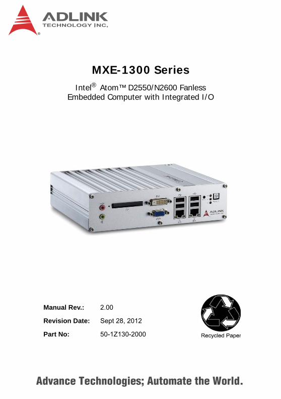
Figure 1-1: MXE-1300 Functional Block Diagram
1.4 Unpacking ChecklistBefore unpacking, check the shipping carton for any damage. Ifthe shipping carton and/or contents are damaged, inform yourdealer immediately. Retain the shipping carton and packingmaterials for inspection. Obtain authorization from your dealerbefore returning any product to ADLINK. Ensure that the fol-lowing items are included in the package.
MXE-1300Screw pack for wall-mounting and HDD installationUser’s ManualADLINK All-in-One DVD
Intel AtomD2550 1.86GHz
Processor
Channel A204 pin SODIMM
Intel NM10Express Chipset
DDR3
800/1066MHz
DMI
GbE controllerIntel 82574L
RJ45 &USB x 2
Connector
RJ45 &USB x 2
Connector
Line out &Mic inJack
COM PortDB-9
Connector x4
GbE I/F
USB 2.0
Audio
COM serial
PCIe x1
PCIe x1GbE controllerIntel 82574L
GbE I/F
USB 2.0
Super I/OLPC
DVI
VGA
DVI-D Connector DVIlevel shifter
SATAConnector
SATA II
CRT Connector
LVDS Internal Slot LVDS
SATAJMD330 CF Card SlotCF
GbE controllerIntel 82574L
RJ45 &USB x 2
Connector
GbE I/F
USB 2.0
PCIe x1
RealtekALC269Q
HDA
DIO DIO x4Connector
6 Introduction
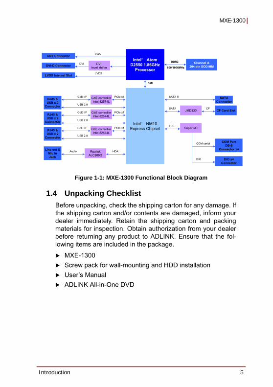
1.5 Mechanical Drawings
Figure 1-2: Top View
NOTE:NOTE:
All dimensions shown are in millimeters (mm) unless otherwise stated.
210
170

Introduction 7
MXE-1300
Figure 1-3: Underside View
Figure 1-4: Front View
4x-M4 THREADED
75
75

8 Introduction
Figure 1-5: Rear View
Figure 1-6: Side View
1.6 Front Panel I/O ConnectorsThis section describes the I/O connectors lcoated on the frontpanel of the MXE-1300.
Figure 1-7: Front Panel I/O
A
B
CD
EF
G
H
I

Introduction 9
MXE-1300
Table 1-1: MXE-1300 Front Panel I/O Connector Legend
1.6.1 Power ButtonThe power button is a non-latched push button with a blue LEDindicator. System is turned on when button is pressed, and thepower LED lit. To shut down the system, the operating system canbe issued shutdown command in or just press the power button. Ifthe system halts, press the button for 5 seconds also can turn offthe system compulsorily.
1.6.2 LED indicatorsBesides the LED attached in the power button, there are threeLED indicators on the front panel. The following table describesthe color and function of the LED indicators.
Table 1-2: LED Indicators
A Power ButtonB LED IndicatorsC Reset ButtonD USB 2.0 connectors (Type A)E Gigabit Ethernet connectorsF VGA connectorG DVI connectorH Compact-flash socketI MIC & speaker jacks
Indicator Color Description
Watchdog (WDT) Yellow When Watchdog Timer is started, flashes and lights when timer is expired.
Hard disk drive Red When the SATA interface device is active, blinks.
Diagnostic Green
If no physical storage device is connected to the system, remians litIf no memory is installed in the SO-DIMM sockets, blinks.

10 Introduction
1.6.3 Reset ButtonThe reset button is used to perform hard reset for the MXE-1300.
1.6.4 VGA ConnectorThe MXE-1300 provides one VGA connector for display on exter-nal (D-sub 15P) monitor.
1.6.5 DVI-D ConnectorThe MXE-1300 provides one DVI-D connector for display on anexternal (DVI-D) monitor.
1.6.6 USB 2.0 ConnectorsThe MXE-1300 provides a total of six USB 2.0 ports using Type AUSB connectors, with four ports on the front and two on the rearpanel. All are compatible with Hi-Speed, full-speed, and low-speedUSB devices. All USB ports share one EHCI controller, and twoUSB ports share one UHCI controller. The MXE-1300 supportsmultiple boot devices, including USB flash drive, USB externalhard drive, USB floppy, USB CD-ROM and etc. The boot priorityand boot device can be configured in BIOS setting.
1.6.7 Compact-Flash PortThe MXE-1300 is equipped with a Type I Compact-Flash socketon the front panel. The CF interface provides +3.3V voltage to theCF card, is transferred from SATA by an ASIC, and can act as analternative storage device for system installation. The MXE-1300can be booted up via a CF card with OS installed. When the CFcard is used as the boot device, it must be installed before system
NOTE:NOTE:
The high impedance of long VGA/DVI cables negatively affects video signal integrity at the receiver side.It is recommended that VGA/DVI cables be less than 2 meters in length with effective shielding, such as UL style 2919 AWM. If video transmission distance is to exceed 10 meters, a VGA/DVI signal repeater or active KVM may provide better results..

Introduction 11
MXE-1300
powerup. For installation details, see “Installing a CF Card” onpage 32..
1.6.8 Gigabit Ethernet (Intel 82574L) The MXE-1300 provides two Gigabit Ethernet ports on the frontpanel, and one on the rear, via the Intel 82574L controller. TheEthernet controller supports the following features:
Advanced error reporting Message signaled interrupts TCP segmentation offload/large-send support 802.3x flow control-compliant IEEE 802.1p and 802.1q support 10/100/1000 IEEE 802.3-compliant Automatic MDI/MDIX crossover at all speeds ACPI 2.0 specification Wake-On-Link feature Preboot eXecution Environment (PXE) flash interface sup-port
1.6.9 Active/Link & Speed LEDs
Figure 1-8: Active/Link & Speed LEDs
Active/Link LEDYellow
Speed LEDGreen/Orange

12 Introduction
Table 1-3: Active/Link LED
Table 1-4: Speed LED
1.6.10 MIC & Speaker JacksThe MXE-1300 implements Intel High Definition audio on theREALTEK ALC269Q chip, with support up to 24-bit, 192 KHz sam-ple rate high quality headphone output and microphone input. Thepink jack is for microphone input, and the green jack for head-phone output.
Color Status Description
Yellow
OFF Ethernet port is disconnected
ON Ethernet port is connected and no data transmission is underway
Flashing Ethernet port is connected and transmitting/receiving data.
Color Status Description
Green/OrangeOFF 10 MbpsGreen 100 MbpsOrange 1000 Mbps

Introduction 13
MXE-1300
1.7 Rear Panel I/O Connectors
Figure 1-9: Rear Panel I/O
Table 1-5: MXE-1300 Rear Panel I/O Connector Legend
1.7.1 DC Power Supply ConnectorThe DC power supply connector consists of three pins, V+, chas-sis ground, and V- from right to left respectively. V+ and V- pinsare for DC power input and chassis ground pin grounds the chas-sis for better EMC compatibility. DC power input of the MXE-1300allows a voltage input range from DC 6 to 36V, with UVP (undervoltage protect of 6V), OVP (over voltage protect of 36V), andreversed polarity protection.
A DC power supply connectorB COM port connectors (DB9 x4)C USB 2.0 connectors (Type A)D Gigabit Ethernet connectorE Digital I/O connectorF Antenna connector (optional)
ABC
F
E

14 Introduction
1.7.2 COM PortsThe MXE-1300 provides 4 COM ports on the rear panel in theform of D-sub 9P connectors, configured as follows. COM1 &COM2 ports can support RS232/RS422/RS485 mode as set inBIOS, see “Serial Port 1~4 Configuration” on page 54..
2x Software-programmable RS-232/422/485 (COM1 & COM2) by DB9 connectors 2x RS-232 (COM3 & COM4) by DB9 connectors
WARNING:
Please ensure that DC power supply is within the input voltage range defined in the specification, stable and low-noise, and provides sufficient operating current.Over- or under-voltage, unstable, or insufficiently powered DC power supply may cause system instability and physical dam-age.
PINSignal name
RS-232 RS-422 RS-485
1 DCD# RXD422n 485n2 RXD RXD422p 485p3 TXD TXD422p N/S4 DTR# TXD422n N/S5 GND N/S N/S6 DSR# N/S N/S
15
69

Introduction 15
MXE-1300
Table 1-6: D-sub 9P signal name of COM1 & COM2 ports
1.7.3 Digital I/O ConnectorThe MXE-1300 provides four channel non-isolation digital inputcircuits and four digital non-isolation output circuits through a ter-minal slot of pitch 3.81mm. Spec and connector pin numberingand definitions are as follows.
Figure 1-10: DI/O Connector Pin Numbering
7 RTS# N/S N/S8 CTS# N/S N/S9 RI# N/S N/S
4-Channel Digital Input 4-Channel Digital Output
Logic high: 2 to 5.25 V
Output type: Open drain N-channel MOSFET driver with internal pull high of 200 Ω resistanceOutput high: 2.4 to 5 V
Logic low: 0 to 0.8 VOutput low: 0 to 0.5 VSource/Sink current for all channels: 24 mA
PINSignal name
RS-232 RS-422 RS-485
1 5
6 10

16 Introduction
Table 1-7: DI/O Connector Pin Definition
Pin Description Pin Description
1 DI 0 6 DO 02 DI 1 7 DO 13 DI 2 8 DO 24 DI 3 9 DO 35 GND 10 GND
+5V
DOoutput
GND
DO
GND
MOSFET
200

Introduction 17
MXE-1300
Figure 1-11: DO Schematic
Figure 1-12: DI Schematic
1.7.4 Antenna ConnectorThe MXE-1300 provides two SMA type antenna connectors suit-able for Wireless LAN and Wireless WAN modules of an internalMini PCI Express card.
+3.3V
DIinput
GND
DI
GND
MOSFET
4.7K
18 Introduction
1.8 Internal I/O Connectors
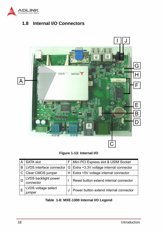
Figure 1-13: Internal I/O
Table 1-8: MXE-1300 Internal I/O Legend
A SATA slot F Mini PCI Express slot & USIM SocketB LVDS interface connector G Extra +3.3V voltage internal connectorC Clear CMOS jumper H Extra +5V voltage internal connector
D LVDS backlight power connector I Reset button extend internal connector
E LVDS voltage select jumper J Power button extend internal connector
A
B
C
D
E
F
HG
JI

Introduction 19
MXE-1300
1.8.1 SATA SlotThe MXE-1300 provides a Gen 2 SATA port at 3.0 Gbit/s, compat-ible with SATA Gen 1 1.5Gbit/s. The SATA host controller sup-ports legacy mode using I/O space and AHCI mode using memoryspace. This SATA connector accepts 2.5” and 3.5” (optional) HDDor solid state disk (SSD). The disk must be installed in the SATAconnector with a HDD bracket. For installation information, see“Installing a Hard Disk Drive” on page 25.
1.8.2 LVDS Interface Connector (optional)The MXE-1300 provides an internal LVDS interface connector,supporting single channel up to 1366*768 24-bit resolution, withpin numbering and definition as follows.
Figure 1-14: LVDS Pin Numbering
1 2

20 Introduction
Table 1-9: LVDS Interface Connector Pin Definition
1.8.3 Clear CMOS JumperUpon encountering an abnormal condition preventing theMXE-1300 from booting, the jumper can clear the BIOS contentstored in CMOS and restore default settings. To clear CMOS,short pin #2 to pin #3 of JP1 and then return to normal mode (shortpin #1 to pin #2).
Table 1-10: Clear CMOS Jumper
Pin Signal Pin Signal
1 +LVDS_VCC 2 +LVDS_VCC
3 GND 4 GND
5 LVDS_CLK+ 6 LVDS_TXP2
7 LVDS_CLK- 8 LVDS_TXN2
9 GND 10 GND
11 LVDS_TXP0 12 LVDS_TXP3
13 LVDS_TXN0 14 LVDS_TXN3
15 GND 16 GND
17 LVDS_TXP1 18 LVDS_DCLK
19 LVDS_TXN1 20 LVDS_DDAT
Normal Clear

Introduction 21
MXE-1300
1.8.4 LVDS Backlight Power Connector (option)The MXE-1300 internal LVDS backlight power connector supports+5V and +12V, with numbering and pin definitions as follows.
Figure 1-15: LVDS Backlight Power Connector Pin Numbering
Table 1-11: LVDS Backlight Power Connector Pin Definition
Pin Description
1 +5V
2 Backlight Enable
3 Backlight Control
4 GND
5 +12V
1

22 Introduction
1.8.5 LVDS Voltage Selected Jumper (optional)The MXE-1300 can support +3.3V and +5V for the LVDS powerpanel, with power of the LVDS interface (+LVDS_VCC) selectedby internal jumper. default jumper setting is 5 V, as follows.
Table 1-12: LVDS Voltage Selected Jumper
1.8.6 Mini PCI Express Slot & USIM SocketThe MXE-1300 features a Mini PCI Express slot providing func-tional expansion with, for example, wireless LAN module, wirelessWAN module, GPS module, and others. Conforms to PCI ExpressMini Card Electromechanical Specification Revision 1.2.
The USIM Socket allows a wireless WAN module for wirelesscommunication with a telecom operator, connected to a Mini PCIExpress module. SIM card and Wireless WAN module can beinstalled to facilitate wireless wide area network communication.
1.8.7 Extra +3.3 V/ +5 V Voltage Internal ConnectorsInternal +3.3V and +5V connectors support up to 1A current of+3.3V and +5V to the Mini PCI Express card if needed, such as forwireless WAN or GPS card. Pin numbering and definition are asfollows.
+LVDS_VCC: +5V +LVDS_VCC: +3.3V
2 2

Introduction 23
MXE-1300
Figure 1-16: +3.3 V/ +5 V Voltage Internal Connectors Pin Numbering
Table 1-13: +3.3 V/ +5 V Voltage Internal Connectors Pin Definition
1.8.8 Reset/Power Button Extension Internal ConnectorInternal reset and power button extension connectors extendpower and reset button function to external controllable devices,with pin numbering and definition of the two connectors as follows.
Pin Description
1 +5V2 GND3 +3.3V4 GND
1234

24 Introduction
Figure 1-17: Reset/Power Button Extension Internal ConnectorPin Numbering
Table 1-14: Reset/Power Button Extension Internal Connector Pin Definitions
Pin Description
1 Power button2 GND3 Reset button4 GND
1
2
3
4

Getting Started 25
MXE-1300
2 Getting StartedThis chapter demonstrates installation of a hard disk drive andCompactFlash card. In addition to connection and use of DI/O,wall-mounting instruction is also provided.
2.1 Installing a Hard Disk Drive Before installing a hard disk drive, remove the bottom cover of thechassis as follows.
1. Use a #3 hex wrench to unscrew all 6 screws (M3 hexbolts) from the front panel.
2. Remove the 4 fixing members from the front panel andremove the panel.

26 Getting Started
3. Remove the 6 screws from the rear panel.
4. Remove the 8 fixing members from the rear panel andremove the panel.

Getting Started 27
MXE-1300
5. Remove the bottom chassis by sliding it off the top chas-sis.
6. The MXE-1300 ships with an attached empty HDDbracket. Unscrew the 4 screws and remove the HDDbracket.
28 Getting Started
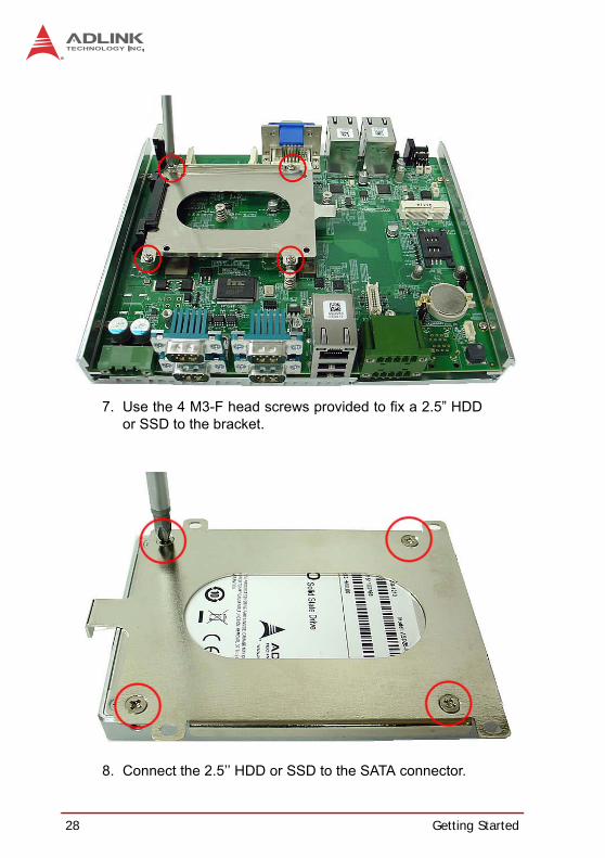
7. Use the 4 M3-F head screws provided to fix a 2.5” HDDor SSD to the bracket.
8. Connect the 2.5’’ HDD or SSD to the SATA connector.
Getting Started 29
MXE-1300
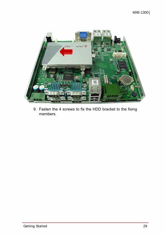
9. Fasten the 4 screws to fix the HDD bracket to the fixingmembers.

30 Getting Started
10.Align the sliding parts as shown and reassemble the bot-tom chassis to the top chassis.

Getting Started 31
MXE-1300
11.Reinstall the front and rear panels and fasten 12 screws(M3 hex bolts) and 12 fixing members into the front andrear panels.

32 Getting Started
2.2 Installing a CF CardThe MXE-1300 series provides a CompactFlash socket on thefront panel to accommodate one CF card. A SATA HDD or SSDand CF card can further be simultaneously installed, and bootdevice preferences set in the BIOS. To install the CF card:
1. Remove and rotate the CF cover to expose the slot.
2. Gently insert the CF card into the CF socket.
Getting Started 33
MXE-1300
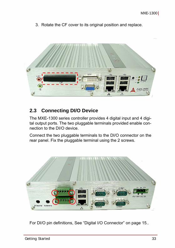
3. Rotate the CF cover to its original position and replace.
2.3 Connecting DI/O DeviceThe MXE-1300 series controller provides 4 digital input and 4 digi-tal output ports. The two pluggable terminals provided enable con-nection to the DI/O device.
Connect the two pluggable terminals to the DI/O connector on therear panel. Fix the pluggable terminal using the 2 screws.
For DI/O pin definitions, See “Digital I/O Connector” on page 15..

34 Getting Started
2.4 Connecting DC power
The MXE-1300 DC power input connector utilizes V+, V- , andchassis ground pins, and accepts input voltage as discussed.
Connect the DC power connector and fix using the 2 screws.
WARNING:
Before providing DC power to the MXE-1300, ensure voltage and polarity provided are compatible with the DC input. Improper input voltage and/or polarity can be responsible for system damage.

Getting Started 35
MXE-1300
2.5 Wall-mounting the MXE-1300The MXE-1300 is shipped with a VESA 100 wall-mount bracketsand accessory screws. The bracket has four M4 mounting holeswith a pitch of 100 mm, allowing fixture to any VESA 100 compati-ble mounting mechanism. The mounting bracket enables theMXE-1300 series controller to be mounted on a wall or the back ofa monitor. To wall-mount the MXE-1300:
1. Prepare the wall-mount brackets and 4 M4 screws pro-vided.

36 Getting Started
2. Fasten the 4 screws to fix the bracket to the desiredmounting surface (wall or monitor) as shown.

Getting Started 37
MXE-1300
3. Fasten the 4 dedicated mounting screws provided intothe holes on the bottom of the MXE-1300.
38 Getting Started
4. Depress the MXE-1300 until a click is heard. The chas-sis is now locked to the mounting bracket
2.6 Cooling ConfigurationHeat-generating components of the MXE-1300 (such as CPU andPCH) are all situated on the left side of the system. These compo-nents directly contact the heat sink via thermal pads and dissipateheat generated by the components. To maximize efficiency of heatdissipation, maintain a minimum of 2 inches (5 cm) clearance onthe top of the MXE-1300.

Driver Installation 39
MXE-1300
3 Driver InstallationAfter installing the operating system, all related drivers must beinstalled for the system to function properly. This section describesthe drivers needed for Windows operating systems and theprocedures to install them. For other OS support, please contactADLINK for further information.
Install drivers as follows.
1. Fully install Microsoft Windows OS before installing anydrivers. Most standard I/O device drivers have beenincluded in Microsoft Windows OS. For Windows 7users, please note that you need Administrator privilegeto install the drivers properly.
2. Install the chipset driver.
3. Install the graphics driver.
4. Install the Ethernet driver.
5. Install the audio driver.
6. Install the WDT (watchdog timer) driver.
7. Install the DI/O driver.
3.1 Installing the chipset driverThis section describes installation of the chipset driver for theMXE-1300. The chipset driver directs the operating system to con-figure the Intel® NM10 chipset components in order to ensure thatthe following features function properly:
SATA Storage Support USB Support
Identification of Intel® Chipset Components in the Device Manager
Microsoft Windows 7 must be fully installed and running on thesystem before installing this software:

40 Driver Installation
The following steps install the chipset driver for the MXE-1300
1. Close any running applications.
2. Insert the ADLINK All-in-One DVD. The chipset driver islocated in the directoryx:\Driver Installation\Matrix\MXE-1300\Chipsetwhere x: denotes the DVD-ROM drive.
3. Execute Setup.exe and follow onscreen instructions tocomplete the setup.
4. After installation is complete, reboot the system.
3.2 Installing the graphics driverThis section describes installation of the graphics driver for theMXE-1300. The MXE-1300 is equipped with the Intel® GraphicsMedia Accelerator Driver package, which supports Windows 7.
To install the graphics driver:
1. Close any running applications.
2. Insert the ADLINK All-in-One DVD. The graphics driveris located in the directoryx:\Driver Installation\Matrix\MXE-1300\Graphicswhere x: denotes the DVD-ROM drive.
3. Execute Setup.exe and follow onscreen instructions tocomplete the setup.
4. After installation is complete, reboot the system.
3.3 Installing the Ethernet driverThis section describes installation of the Ethernet driver for theMXE-1300. To install the driver for the Intel 82547 Gigabit Ether-net controller:
1. Close any running applications.
2. Insert the ADLINK All-in-One DVD. The Ethernet driveris located in the directory

Driver Installation 41
MXE-1300
x:\Driver Installation\Matrix\MXE-1300\LAN-Intel\where x: denotes the DVD-ROM drive.
3. Execute setup.exe and follow onscreen instructions tocomplete the setup.
4. After installation is complete, reboot the system.
3.4 Installing the audio driverThis section describes installation of the audio driver for theMXE-1300. The MXE-1300 supports High Definition audio usingthe Realtek ALC269 audio codec. To install the audio driver:
1. Close any running applications.
2. Insert the ADLINK All-in-One DVD. The audio driver islocated in the directoryx:\Driver Installation\Matrix\MXE-1300\Audio\where x: denotes the DVD-ROM drive.
3. Execute Setup.exe and follow onscreen instructions tocomplete the setup.
4. After installation is complete, reboot the system.
3.5 Installing the WDT and DI/O driversA WDT (watchdog timer) is a hardware mechanism resetting thesystem when the operating system or application is halted. A typi-cal usage of WDT is to start the timers and periodically reset thetimer, and when timer is expired, the system resets. The WDTdriver must be installed to program the WDT.
The MXE-1300 also provides 4 channel DI and 4 channel DO.WDT and DI/O Driver/ API driver packages must be installed toaccess and use the DI/O feature.
To install the WDT and DI/O drivers for the MXE-1300:
Close any running applications.
Ensure you have Administrator privilege.
Download Microsoft® Visual C++ 2005 Redistributable Packagex86 or x64 version from: http://www.microsoft.com/en-us/down-load/details.aspx?id=3387

42 Driver Installation
Insert the ADLINK All-in-One DVD. The WDT driver is located inthe directory:x:\Driver Installation\Matrix\MXE-1300\WDT_DI/O\where x denotes the DVD-ROM drive.
Run Setup.exe and follow the onscreen instructions to completesetup.
After complete installation, reboot the system.
WDT, DI/O API library and sample programs are located in theMXE1300_WDT folder, default location of “C:\ProgramFiles\ADLINK\MXE1300_WDT”
NOTE:NOTE:
Administrator privilege is required to use the WDT API in Windows 7.

Watchdog Timer (WDT) & DI/O Function Libraries 43
MXE-1300
Appendix A: Watchdog Timer (WDT) &DI/O Function Libraries
This appendix describes use of the watchdog timer (WDT) func-tion library for the MXE-1300.
The watchdog timer is a hardware mechanism provided to resetthe system if the operating system or an application stalls. Afterstarting, the watchdog timer in the application must be periodicallyreset before the timer expires. Once the watchdog timer expires, ahardware-generated signal is sent to reset the system.
DI/O provides input/output to support inter-device communica-tions. Simple programming guides allow easy transmission of digi-tal signals between the system and attached peripherals.
A.1 WDT with API/WindowsMatrix WDT API library files and a demo program (incl. sourcecode) can be found on the included driver CD or downloaded fromhttp://www.adlinktech.com.
To use the WDT function library for MXE-1300 series, include theheader file WDT.h and linkage library WDT.lib in the C++ project.
InitWDT Initializes watchdog timer function of MXE-1300. InitWDT mustbe called before the invocation of any other WDT function.
@ SyntaxC/C++
BOOL InitWDT()
@ ParametersNone
@ Return codeTRUE if watchdog timer is successfully initialized.
FALSE if watchdog timer fails to initialize.

44 Watchdog Timer (WDT) & DI/O Function Libraries
SetWDTSets the timeout value of the watchdog timer. There are twoparameters for this function to indicate the timeout ticks andunit. ResetWDT or StopWDT should be called before the expi-ration of watchdog timer, or the system will reset.
@ SyntaxC/C++
BOOL SetWDT(BYTE tick, BYTE unit)
@ Parameterstick
Specify the number of ticks for watchdog timer. A valid valueis 1 - 255.
unit
Specify the timeout ticks of the watchdog timer.
@ Return codesTRUE if timeout value of watchdog timer is successfully set.
FALSE if timeout value of watchdog timer is failed to set.
StartWDT Starts watchdog timer function. Once the StartWDT is invoked,the watchdog timer starts. ResetWDT or StopWDT should becalled before the expiration of watchdog timer, or the systemwill reset.
@ SyntaxC/C++
BOOL StartWDT()
Value Description
0The unit for one tick is one second. For example, when one tick is specified as 100 and the unit as 0, the timeout value is 100 seconds.
1The unit for one tick is one minute. For example, whenone tick is specified as 100 and the unit as 1, the timeout value is 100 minutes.

Watchdog Timer (WDT) & DI/O Function Libraries 45
MXE-1300
@ ParametersNone
@ Return codesTRUE if watchdog timer is successfully started.
FALSE if watchdog timer is failed to start.
ResetWDT Resets the watchdog timer. The invocation of ResetWDTallows restoration of the watchdog timer to the initial timeoutvalue specified in SetWDT function. ResetWDT or StopWDTshould be called before the expiration of the watchdog timer, orthe system will reset.
@ SyntaxC/C++
BOOL ResetWDT()
@ ParametersNone
@ Return codesTRUE if watchdog timer is successfully reset.
FALSE if watchdog timer fails to reset.
StopWDT Stops the watchdog timer.
@ SyntaxC/C++
BOOL StopWDT()
@ ParametersNone
@ Return codesTRUE if watchdog timer is successfully stopped.

46 Watchdog Timer (WDT) & DI/O Function Libraries
FALSE if watchdog timer fails to stop.
A.2 DI/O with API/WindowsMatrix DI/O API library files and a demo program (incl. sourcecode) are located on the included driver CD or downloaded fromhttp://www.adlinktech.com.
DI/O functions are as follows.
GPIO_Init Reserves system resources for digital input/output API ser-vice.It is necessary to call this function before using other MXE-1300 DI/O functions.
@ SyntaxC/C++
I16 GPIO_Init(void)
@ ParametersNone
@ Return codeNoError
ErrorOpenDriverFailed
ErrorDeviceIoctl
GPI_Read() Reads the digital logic state of the digital input line..
@ SyntaxC/C++
I16 GPI_Read(U16 *pwState)
@ ParameterspwState
Returns the digital logic state of MXE-1300 digital input chan-nels 1~4 (bit 0~3)
@ Return code

Watchdog Timer (WDT) & DI/O Function Libraries 47
MXE-1300
NoError
ErrorOpenDriverFailed
ErrorDeviceIoctl
GPO_Write()Sets the digital logic state of the digital output line.
@ SyntaxC/C++
I16 GPO_Write(U16 wState)
@ ParametersState
Sets the digital logic state of MXE-1300 digital output channels1~4 (bit 0~3) to 0 or 1.
@ Return codeNoError
ErrorOpenDriverFailed
ErrorDeviceIoctl
GPO_Read()Reads the digital logic state of the digital output line.
@ SyntaxC/C++
I16 GPO_Read(U16 *pwState)
@ ParameterspwState
Returns the digital logic state of MXE-1300 digital output chan-nels 1~4 (bit 0~3).
@ Return codeNoError
ErrorOpenDriverFailed
ErrorDeviceIoctl

48 Watchdog Timer (WDT) & DI/O Function Libraries
This page intentionally left blank.

BIOS Setup 49
MXE-1300
Appendix B: BIOS Setup
The Basic Input/Output System (BIOS) is a program that providesa basic level of communication between the processor andperipherals. In addition, the BIOS also contains codes for variousadvanced features applied to the MXE-1300. The BIOS setupprogram includes menus for configuring settings and enablingfeatures of the MXE-1300 series. Most users do not need to usethe BIOS setup program, as the MXE-1300 ships with defaultsettings that work well for most configurations.
NOTE:NOTE:
BIOS options in the manual are for reference only, and are subject to configuration. Users can contact their hardware pro-vider for the latest BIOS version.
WARNING:
Changing BIOS settings may lead to incorrect controller behav-ior and possible inability to boot. In such a case, Section 1.8.3 on page 20 provides instruction on clearing the CMOS and restoring default settings

50 BIOS Setup
B.1 MainContains basic system information for the MXE-1300.
B.1.1 BIOS InformationBIOS Vendor: Provider of the BIOS code
Core Version
BIOS Version: Current BIOS version
B.1.2 PC Health StatusIndicates CPU Temperature and voltages for CPU, VGFX,+1.05V, +3.3V, +1.5V, +5V, +12.0V, VBAT.
B.1.3 System Time/System DateThis option changes the system time and date. Highlight Sys-tem Time or System Date using the up or down <Arrow> keys.

BIOS Setup 51
MXE-1300
Enter new values using the keyboard then press <Enter> key.Press the < Tab > key to move between fields. The date mustbe entered in MM/DD/YY format. The time is entered inHH:MM:SS format.
B.2 Advanced
Accesses advanced options of the MXE-1300.
NOTE:NOTE:
The time is in 24-hour format. For example, 5:30 A.M. appears as 05:30:00, and 5:30 P.M. as 17:30:00.
CAUTION:
Setting incorrect or conflicting values in Advanced BIOS Setup may cause system malfunction

52 BIOS Setup
B.2.1 CPU Configuration
Displays:
Processor TypeEMT64 SupportProcessor SpeedSystem Bus SpeedRatio StatusActual RatioProcessor SteppingMicrocode RevisionL1 Cache RAML2 Cache RAMProcessor CoreHyper-threading Support

BIOS Setup 53
MXE-1300
And settings for
Hyper-ThreadingEnabled for Windows XP and Linux (OS is optimized for Hyper-Threading Technology) and disabled for other OS (OS not opti-mized for Hyper-Threading Technology).
Execute Disable BitEnabled in XP, can prevent certain classes of malicious bufferoverflow attacks when combined with a supporting OS.
Limit CPUID MaximumDisabled for Windows XP.
B.2.2 Onboard Device Configuration

54 BIOS Setup
Serial Port 1~4 ConfigurationPort type (RS-232/422/485) is controllable for Serial Ports 1 and 2only.
Intel 82574L LAN #1Enables/Disables onboard Intel 82574L LAN controller.
Launch Intel 82574 LAN PXE OpROMEnables/Disables execution of LAN boot-rom to add boot optionfor legacy network devices.
Intel 82574L LAN #2Enables/Disables onboard Intel 82574L LAN controller.
Launch Intel 82574 LAN PXE OpROMEnables/Disables execution of LAN boot-rom to add boot optionfor legacy network devices.
Intel 82574L LAN #3Enables/Disables onboard Intel 82574L Lan controller.
Launch Intel 82574 LAN PXE OpROMEnables/Disables execution of LAN boot-rom to add boot optionfor legacy network devices.
SATA Controller(s)Enables/Disables internal serial ATA controller.
SATA Mode SelectionAllows selection of SATA channel configuration, from IDE Mode orAHCI Mode

BIOS Setup 55
MXE-1300
Legacy USB SupportEnables Legacy USB Support, with AUTO disabling if no USBdevices are connected, and DISABLE maintaining USB devicesavailable only for EFI applications.
B.2.3 Advanced Power Management
Restore AC Power Loss Determines the state the computer will enter when power isrestored after a power loss, from among Last State, Power On andPower Off, as follows
Option Description
Power Off When enabled, powers off the system when power is restored.
Power On When enabled, powers on the system when power is restored.

56 BIOS Setup
System WatchdogEnables/disables system internal watchdog to prevent boot failureat system POST stage.
Wake System With Fixed TimeEnables/disables system wake on alarm event.
Wake On RingEnables/disables system wake on RI event.
B.2.4 SATA Configuration
Last StateWhen enabled, powers the system off or on depending on the previous system power state while power is restored.
Option Description

BIOS Setup 57
MXE-1300
Displays status ionformation for:
SATA Port
CF Port
And allows setting of CF Port Hot Plug.
B.2.5 Serial Port Console Redirection
Provides redirection and settings for COMs 1 to 4.
Also displays current status of miscellaneous parameters for COMPorts.
As well, the following Serial Port for Out-of-Band Management/EMS settings can be made:
58 BIOS Setup
Console RedirectionEnables Console Redirection function for remote management ofa Windows Server OS through the port selected by Out-of-BandMgmt Port.
Out-of-Band Mgmt PortSelects the COM Port for remote management of a Windows OS.
Terminal TypeSelects the transmission protocol for remote terminal console.
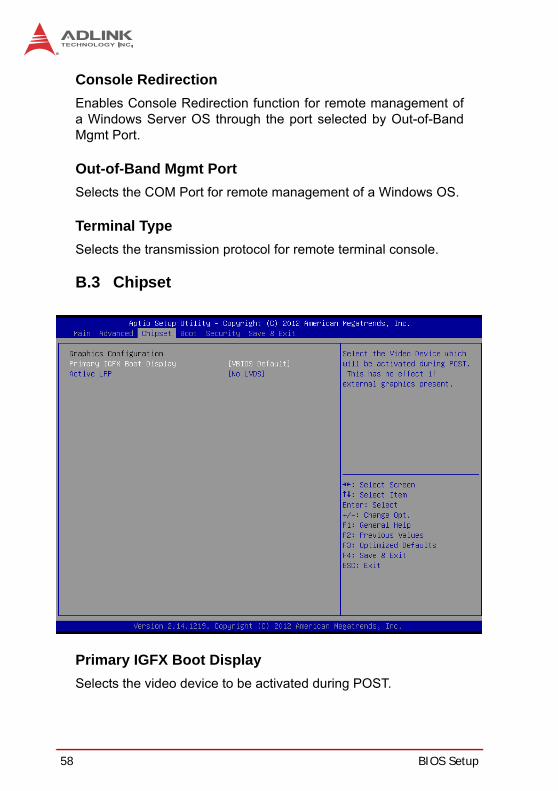
B.3 Chipset
Primary IGFX Boot DisplaySelects the video device to be activated during POST.

BIOS Setup 59
MXE-1300
Active LFPSelects the Active LFP configuration.
B.4 Boot
Setup Prompt TimeoutSets the number of seconds for the setup activation key (“DEL”) toremain active.
Bootup Num-Lock StateAllows the Number Lock setting to be modified during boot.
Quiet Boot When disabled, BIOS displays POST messages, and whenenabled, BIOS displays the OEM logo.

60 BIOS Setup
Fast Boot When disabled, BIOS performs all POST tests. When enabled,BIOS to skips selected POST tests to boot faster.
Boot Option PrioritiesSpecifies the priority of boot devices. All installed boot devices aredetected during POST and displayed. Selection of the target BootOption # selects the desired boot device.
Hard Drive BBS PrioritiesSelects the HDD to be displayed in the Boot Option Priorities list-ing when multiple HDD are present.
NOTE:NOTE:
While enabling Fast Boot can reduce the ready time of system, some startup parameters will be assumed and may not func-tion as expected.

BIOS Setup 61
MXE-1300
B.5 Security
If only the Administrator’s password is set, only access to Setup islimited and requests the password. If only User’s password is set,the password is requested at power up to boot or enter Setup, inwhich the user is grated Administrator rights.
Administrator PasswordSets Setup Administrator password
User PasswordSets Boot/Setup User password

62 BIOS Setup
B.6 Save & Exit
Discard Changes and Exit Discards all changes and exits BIOS setup.
Save Changes and ResetSaves all changes and reboots the system to activate new set-tings.
Discard ChangesResets system setup without saving any changes.
Restore Defaults Resets all BIOS options to the complete default settings. Defaultsettings, while designed for maximum system stability, may impact

BIOS Setup 63
MXE-1300
performance. Restore Defaults Setup is indicated if the computerencounters system configuration problems.
Save as User DefaultsSaves all changes made as user defaults.
Restore User DefaultsRestores the user defaults to all setup options.
Launch EFI Shell from filesystem deviceAttempts to launch an EFI Shell application (Shellx64.efi) from oneavailable filesystem device.

64 BIOS Setup
This page intentionally left blank.

Important Safety Instructions 65
MXE-1300
Important Safety Instructions
For user safety, please read and follow all instructions,WARNINGS, CAUTIONS, and NOTES marked in this manualand on the associated equipment before handling/operating theequipment.
Read these safety instructions carefully.Keep this user’s manual for future reference.Read the specifications section of this manual for detailed information on the operating environment of this equipment.When installing/mounting or uninstalling/removing equipment:
Turn off power and unplug any power cords/cables.To avoid electrical shock and/or damage to equipment:
Keep equipment away from water or liquid sources;Keep equipment away from high heat or high humidity;Keep equipment properly ventilated (do not block or cover ventilation openings);Make sure to use recommended voltage and power source settings;Always install and operate equipment near an easily accessible electrical socket-outlet;Secure the power cord (do not place any object on/over the power cord);Only install/attach and operate equipment on stable surfaces and/or recommended mountings; and,If the equipment will not be used for long periods of time, turn off and unplug the equipment from its power source.

66 Important Safety Instructions
Never attempt to fix the equipment. Equipment should only be serviced by qualified personnel.
A Lithium-type battery may be provided for uninterrupted, backupor emergency power.
Equipment must be serviced by authorized technicians when:
The power cord or plug is damaged;Liquid has penetrated the equipment;It has been exposed to high humidity/moisture;It is not functioning or does not function according to the user’s manual;It has been dropped and/or damaged; and/or,It has an obvious sign of breakage.
WARNING:
There is risk of explosion if the battery is replaced with an incorrect type. Dispose of used batteries appropriately.

Getting Service 67
MXE-1300
Getting Service
Contact us should you require any service or assistance.
ADLINK Technology, Inc. Address: 9F, No.166 Jian Yi Road, Zhonghe District New Taipei City 235, Taiwan
166 9Tel: +886-2-8226-5877 Fax: +886-2-8226-5717 Email: [email protected]
Ampro ADLINK Technology, Inc. Address: 5215 Hellyer Avenue, #110, San Jose, CA 95138, USA Tel: +1-408-360-0200 Toll Free: +1-800-966-5200 (USA only) Fax: +1-408-360-0222 Email: [email protected]
ADLINK Technology (China) Co., Ltd. Address: 300 (201203) 300 Fang Chun Rd., Zhangjiang Hi-Tech Park,
Pudong New Area, Shanghai, 201203 China Tel: +86-21-5132-8988 Fax: +86-21-5132-3588 Email: [email protected]
ADLINK Technology Beijing Address: 1 E 801 (100085)
Rm. 801, Power Creative E, No. 1, B/D Shang Di East Rd., Beijing, 100085 China
Tel: +86-10-5885-8666 Fax: +86-10-5885-8625 Email: [email protected]
ADLINK Technology Shenzhen Address:
A1 2 C (518057) 2F, C Block, Bldg. A1, Cyber-Tech Zone, Gao Xin Ave. Sec. 7, High-Tech Industrial Park S., Shenzhen, 518054 China
Tel: +86-755-2643-4858 Fax: +86-755-2664-6353 Email: [email protected]

68 Getting Service
ADLINK Technology, Inc. (French Liaison Office) Address: 15 rue Emile Baudot, 91300 Massy CEDEX, France Tel: +33 (0) 1 60 12 35 66 Fax: +33 (0) 1 60 12 35 66 Email: [email protected]
ADLINK Technology Japan Corporation Address: 101-0045 3-7-4
374 4F KANDA374 Bldg. 4F, 3-7-4 Kanda Kajicho, Chiyoda-ku, Tokyo 101-0045, Japan
Tel: +81-3-4455-3722 Fax: +81-3-5209-6013 Email: [email protected]
ADLINK Technology, Inc. (Korean Liaison Office) Address: 1675-12 8
8F Mointer B/D,1675-12, Seocho-Dong, Seocho-Gu, Seoul 137-070, Korea
Tel: +82-2-2057-0565 Fax: +82-2-2057-0563 Email: [email protected]
ADLINK Technology Singapore Pte. Ltd. Address: 84 Genting Lane #07-02A, Cityneon Design Centre,
Singapore 349584 Tel: +65-6844-2261 Fax: +65-6844-2263 Email: [email protected]
ADLINK Technology Singapore Pte. Ltd. (Indian Liaison Office) Address: 1st Floor, #50-56 (Between 16th/17th Cross) Margosa Plaza,
Margosa Main Road, Malleswaram, Bangalore-560055, India Tel: +91-80-65605817, +91-80-42246107 Fax: +91-80-23464606 Email: [email protected]
ADLINK Technology, Inc. (Israeli Liaison Office) Address: 6 Hasadna St., Kfar Saba 44424, Israel Tel: +972-9-7446541 Fax: +972-9-7446542 Email: [email protected]
Related Documents