SERVICE MANUAL MX775 MX800 MX825 7UD-F8197-E0 LIT-19616-02-37

Welcome message from author
This document is posted to help you gain knowledge. Please leave a comment to let me know what you think about it! Share it to your friends and learn new things together.
Transcript

SERVICE MANUAL
MX775MX800MX825
7UD-F8197-E0LIT-19616-02-372016.12×1 !
7UD-F8197-E0_Cover.indd 1 2016/12/13 11:23:58

7UD-F8197-E0_Cover.indd 2 2016/12/13 11:23:58

MX775, MX800, MX825SERVICE MANUAL
©2016 by Yamaha MotorCorporation, U.S.A.
1st Edition, December 2016All rights reserved. Any reprinting orunauthorized use without the written
permission of Yamaha MotorCorporation, U.S.A.
is expressly prohibited.LIT-19616-02-37

IMPORTANT
This manual was produced by the Yamaha Motor Powered Products Co., Ltd. primarily for use byYamaha dealers and their qualified mechanics. It is not possible to include all the knowledge of amechanic in one manual. Therefore, anyone who uses this book to perform maintenance andrepairs on Yamaha machines should have a basic understanding of mechanics and the techniquesto repair these types of machines. Repair and maintenance work attempted by anyone without thisknowledge is likely to render the machine unsafe and unfit for use.This model has been designed and manufactured to perform within certain specifications in regardto performance and emissions. Proper service with the correct tools is necessary to ensure that themachine will operate as designed. If there is any question about a service procedure, it is imperativethat you contact a Yamaha dealer for any service information changes that apply to this model. Thispolicy is intended to provide the customer with the most satisfaction from his machine and to con-form to federal environmental quality objectives.Yamaha Motor Powered Products Co., Ltd. is continually striving to improve all of its models. Modifi-cations and significant changes in specifications or procedures will be forwarded to all authorizedYamaha dealers and will appear in future editions of this manual where applicable.
TIP
• This Service Manual contains information regarding periodic maintenance to the emission controlsystem. Please read this material carefully.
• Designs and specifications are subject to change without notice.
IMPORTANT MANUAL INFORMATION
Particularly important information is distinguished in this manual by the following notations.
This is the safety alert symbol. It is used to alert you to potential personal injury hazards.Obey all safety messages that follow this symbol to avoid possible injury or death.
A WARNING indicates a hazardous situation which, if not avoided, could result in death orserious injury.
A NOTICE indicates special precautions that must be taken to avoid damage to the machineor other property.
TIPA TIP provides key information to make procedures easier or clearer.
WARNING
NOTICE

HOW TO USE THIS MANUAL
This manual is intended as a handy, easy-to-read reference book for the mechanic.Comprehensive explanations of all installation, removal, disassembly, assembly, repair and checkprocedures are laid out with the individual steps in sequential order.• The manual is divided into chapters and each chapter is divided into sections. The current section
title is shown at the top of each page “1”.• Sub-section titles appear in smaller print than the section title “2”.• To help identify parts and clarify procedure steps, there are exploded diagrams at the start of each
removal and disassembly section “3”.• Numbers are given in the order of the jobs in the exploded diagram. A number indicates a disas-
sembly step “4”.• Symbols indicate parts to be lubricated or replaced “5”.
Refer to SYMBOLS.• A job instruction chart accompanies the exploded diagram, providing the order of jobs, names of
parts, notes in jobs, etc. “6”. This step explains removal procedure only. For installation, reversethe steps.
• Jobs requiring more information (such as special tools and technical data) are described sequen-tially “7”.
1
3
7
2
4
5
6
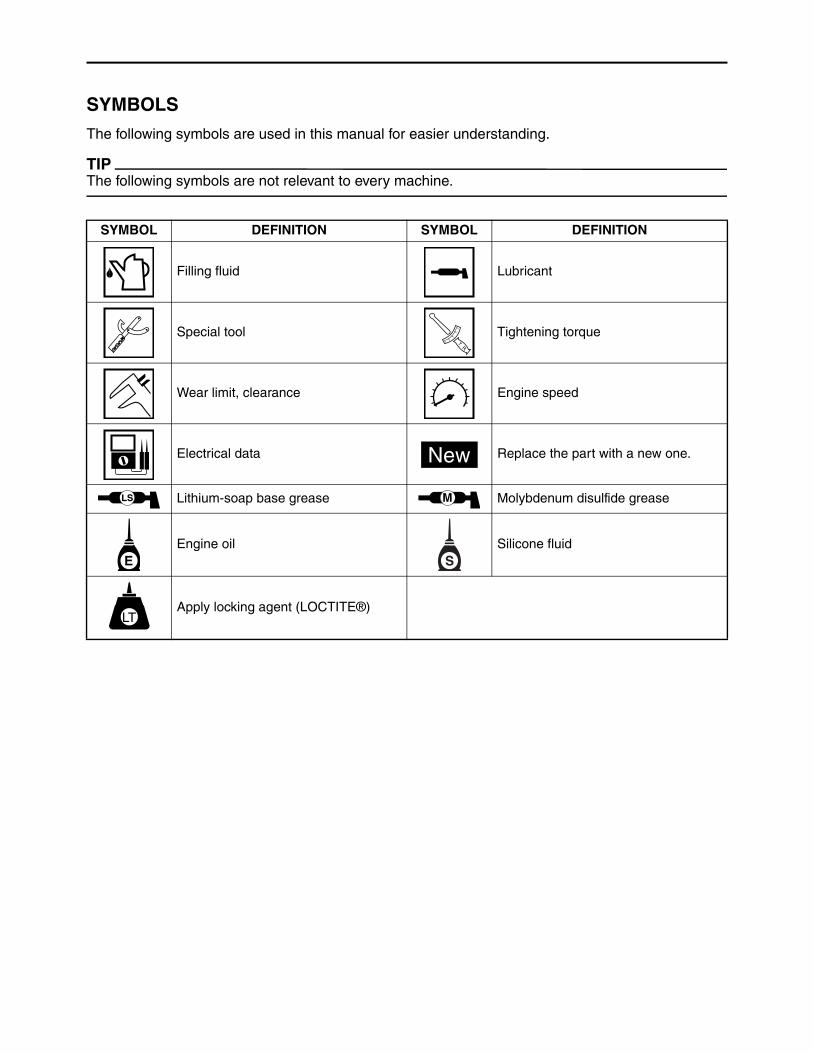
SYMBOLS
The following symbols are used in this manual for easier understanding.
TIP
The following symbols are not relevant to every machine.
SYMBOL DEFINITION SYMBOL DEFINITION
Filling fluid Lubricant
Special tool Tightening torque
Wear limit, clearance Engine speed
Electrical data Replace the part with a new one.
Lithium-soap base grease Molybdenum disulfide grease
Engine oil Silicone fluid
Apply locking agent (LOCTITE®)
T R..
New
LS M
E S
LT
GENERAL INFORMATION
PERIODIC CHECKS AND ADJUSTMENTS
ENGINE
FUEL
ELECTRICAL
TROUBLESHOOTING
SPECIFICATIONS
1
2
3
4
5
6
7
8
9
10
INDEX

MEMO
TABLE OF CONTENTS
GENERAL INFORMATION
MACHINE IDENTIFICATION ......................1-1SERIAL NUMBER .................................1-1STARTING SERIAL NUMBER...............1-1
DIMENSIONS .............................................1-2TOP .......................................................1-2MOUNTING BASE ................................1-2REAR.....................................................1-3REAR (For models equipped with a muffler) ..................................................1-3RIGHT SIDE ..........................................1-4RIGHT SIDE (For models equipped with a muffler) ........................................1-4
IMPORTANT INFORMATION .....................1-5PREPARATION FOR REMOVAL AND DISASSEMBLY......................................1-5CAUTION ON SERVICE........................1-5NOTES ON SERVICE ...........................1-5ALL REPLACEMENT PARTS................1-6GASKETS, OIL SEALS, AND O-RINGS ...............................................1-6BEARINGS AND OIL SEALS ................1-7
BASIC SERVICE INFORMATION ..............1-7ELECTRICAL SYSTEM.........................1-7
SPECIAL TOOLS AND TESTERS...........1-11
PERIODIC CHECKS AND ADJUSTMENTS
INTRODUCTION.........................................2-1
MAINTENANCE INTERVALS CHART .......2-1
PERIODIC MAINTENANCE/LUBRICATION INTERVALS.......................2-1
PERIODIC MAINTENANCE .......................2-2SPARK PLUGS......................................2-2MUFFLER (For models equipped with a muffler) ....2-3ENGINE OIL LEAKAGE ........................2-4ENGINE OIL LEVEL..............................2-5REPLACING THE ENGINE OIL ............2-6FUEL LEAKAGE....................................2-8FUEL FILTER ........................................2-8
OIL COOLER ........................................ 2-9AIR FILTER ELEMENT ......................... 2-9ADJUSTING THE VALVE CLEARANCE ........................................ 2-9CYLINDER HEADS DECARBONIZATION.......................... 2-13ENGINE SPEED ................................. 2-14ADJUSTING THE ENGINE SPEED.... 2-15LOW ENGINE SPEED (Replace the throttle body) ....................................... 2-16FITTINGS AND FASTENERS............. 2-16
ENGINE
ENGINE INSPECTION............................... 3-1MEASURING THE COMPRESSION PRESSURE .......................................... 3-1
AIR FILTER ................................................ 3-3
MUFFLER (For models equipped with a muffler) ...................................................... 3-4
OIL COOLER ............................................. 3-5REMOVING THE OIL COOLER............ 3-6CHECKING THE OIL COOLER............ 3-6INSTALLING THE OIL COOLER .......... 3-6
ECU, RECTIFIER/REGULATOR, AND FUSES........................................................ 3-8
INSTALLING THE FUSES .................... 3-9
IGNITION COILS...................................... 3-10
CASE AND FAN....................................... 3-11REMOVING THE CASE AND FAN ..... 3-12CHECKING THE CASE AND FAN...... 3-13INSTALLING THE CASE AND FAN .... 3-13
FLYWHEEL AND STATOR COIL ASSEMBLY .............................................. 3-15
REMOVING THE FLYWHEEL AND STATOR COIL ASSEMBLY ................. 3-16CHECKING THE FLYWHEEL AND STATOR COIL ASSEMBLY ................. 3-17INSTALLING THE FLYWHEEL AND STATOR COIL ASSEMBLY ................. 3-17INSTALLING THE CRANKSHAFT POSITION SENSOR........................... 3-19

CYLINDER HEAD COVERS, CYLINDER HEADS......................................................3-20
CYLINDER HEAD #1 ..........................3-20CYLINDER HEAD #2 ..........................3-22CHECKING THE ROCKER ARMS AND ROCKER ARM SHAFTS.............3-24CHECKING THE PUSH RODS ...........3-24REMOVING THE CYLINDER HEADS ................................................3-24CHECKING THE CYLINDER HEADS ................................................3-24INSTALLING THE CYLINDER HEAD ASSEMBLY..........................................3-25
VALVES ....................................................3-27REMOVING THE VALVES AND VALVE SPRINGS.................................3-28CHECKING THE VALVES AND VALVE SPRINGS.................................3-28CHECKING THE VALVE SEATS .........3-30VALVE LAPPING .................................3-31INSTALLING THE VALVES AND VALVE SPRINGS.................................3-32
OIL PUMP.................................................3-33DISASSEMBLING THE OIL PUMP.....3-34CHECKING THE OIL PUMP ...............3-34CHECKING THE RELIEF VALVE........3-35CHECKING THE CRANKCASE COVER 2 .............................................3-35INSTALLING THE OIL PRESSURE SWITCH ..............................................3-35ASSEMBLING THE OIL PUMP...........3-36INSTALLING THE CRANKCASE COVER 2 .............................................3-37
PISTONS, CAMSHAFT, CRANKCASE, AND CRANKSHAFT ................................3-38
CRANKCASE ......................................3-38PISTONS, CAMSHAFT, AND CRANKSHAFT ....................................3-40REMOVING THE FLYWEIGHT SHAFT ASSEMBLY AND GOVERNOR FORK.............................3-41DISASSEMBLING THE FLYWEIGHT SHAFT ASSEMBLY.............................3-41CHECKING THE FLYWEIGHT SHAFT ASSEMBLY.............................3-41ASSEMBLING THE FLYWEIGHT SHAFT ASSEMBLY.............................3-42
INSTALLING THE FLYWEIGHT SHAFT ASSEMBLY AND GOVERNOR FORK ............................ 3-42REMOVING THE CAMSHAFT AND VALVE LIFTERS ................................. 3-43CHECKING THE CAMSHAFT ............ 3-43CHECKING THE VALVE LIFTERS ..... 3-44CHECKING THE REED VALVE .......... 3-45INSTALLING THE VALVE LIFTERS AND CAMSHAFT................................ 3-45INSTALLING THE COVER 1............... 3-45INSTALLING THE COVER 2............... 3-46CHECKING THE CRANKCASE COVER 1 ............................................ 3-46INSTALLING THE CRANKCASE COVER 1 ............................................ 3-47CHECKING THE CYLINDERS AND PISTONS ............................................ 3-47CHECKING THE CRANKCASE.......... 3-49CHECKING THE PISTON PINS ......... 3-49CHECKING THE PISTON RINGS ...... 3-49CHECKING THE CRANKSHAFT........ 3-51CHECKING THE CONNECTING RODS OIL CLEARANCE .................... 3-52INSTALLING THE PISTONS AND PISTON RINGS .................................. 3-52INSTALLING THE CRANKSHAFT...... 3-54
FUEL
FUEL PUMPS ............................................ 4-1REMOVING THE HIGH-PRESSURE FUEL PUMP.......................................... 4-2CHECKING THE LOW-PRESSURE FUEL PUMP.......................................... 4-3CHECKING THE HIGH-PRESSURE FUEL PUMP.......................................... 4-3INSTALLING THE HIGH-PRESSURE FUEL PUMP.......................................... 4-4
THROTTLE BODY ASSEMBLY ................. 4-6REMOVING THE THROTTLE BODY ASSEMBLY ........................................... 4-7CHECKING THE THROTTLE BODY ASSEMBLY ........................................... 4-7INSTALLING THE THROTTLE BODY ASSEMBLY ........................................... 4-7

FUEL INJECTORS AND INTAKE MANIFOLD .................................................4-9
REMOVING THE FUEL INJECTORS ........................................4-11INSTALLING THE FUEL INJECTORS ........................................4-12REMOVING THE MANIFOLD ABSOLUTE PRESSURE SENSOR ....4-14INSTALLING THE MANIFOLD ABSOLUTE PRESSURE SENSOR ....4-14REMOVING THE INTAKE MANIFOLD ..........................................4-14CHECKING THE INTAKE MANIFOLD ..........................................4-15INSTALLING THE INTAKE MANIFOLD ..........................................4-15
ELECTRICAL
CIRCUIT DIAGRAM....................................5-1
FUEL INJECTION SYSTEM.......................5-3FI DIAG TOOL INSTRUCTIONS ...........5-3FUEL INJECTION DIAGRAM................5-9ERROR CODE LIST............................5-10DIAG CODE LIST................................5-11FUEL INJECTION SYSTEM TROUBLESHOOTING.........................5-12
ELECTRICAL COMPONENTS.................5-25CHECKING THE SWITCH CONTINUITY.......................................5-27CHECKING THE FUSES ....................5-27CHECKING THE OIL PRESSURE SWITCH ..............................................5-28CHECKING MANIFOLD ABSOLUTE PRESSURE SENSOR.........................5-29CHECKING THE THROTTLE POSITION SENSOR ...........................5-29CHECKING THE CRANKSHAFT POSITION SENSOR ...........................5-30CHECKING THE ENGINE TEMPERATURE SENSOR..................5-31CHECKING THE IGNITION COILS.....5-32CHECKING THE IGNITION SPARK GAP .....................................................5-33CHECKING THE SPARK PLUG CAPS...................................................5-33
CHECKING THE STATOR COIL ASSEMBLY ......................................... 5-34CHECKING THE RECTIFIER/REGULATOR ...................................... 5-35CHECKING THE FUEL INJECTORS........................................ 5-35CHECKING THE STARTER MOTOR OPERATION ....................................... 5-36
ELECTRIC STARTING SYSTEM............. 5-37REMOVING THE STARTER MOTOR ............................................... 5-37DISASSEMBLING THE STARTER MOTOR ............................................... 5-38CHECKING THE ARMATURE COIL... 5-39CHECKING THE BRUSH ................... 5-40CHECKING THE STARTER RELAY ... 5-40ASSEMBLING THE STARTER MOTOR ............................................... 5-40
TROUBLESHOOTING
ENGINE DOES NOT START...................... 6-1IGNITION SYSTEM .............................. 6-1ELECTRIC STARTING SYSTEM ......... 6-2FUEL INJECTION SYSTEM ................. 6-2FUEL PUMP SYSTEM.......................... 6-2
OTHER TROUBLES................................... 6-3ENGINE STARTS BUT STALLS............ 6-3ENGINE SPEED DOES NOT INCREASE............................................ 6-4ENGINE SPEED IS UNEVEN............... 6-5THE BATTERY IS NOT CHARGED ...... 6-5GOVERNOR OPERATION.................... 6-6
OIL PRESSURE SYSTEM ......................... 6-6
SPECIFICATIONS
GENERAL SPECIFICATIONS ................... 7-1
MAINTENANCE SPECIFICATIONS .......... 7-3ENGINE ................................................ 7-3ELECTRICAL........................................ 7-7
TIGHTENING TORQUES........................... 7-8

GENERAL TORQUE SPECIFICATIONS ....................................7-10
LUBRICATION POINTS AND TYPE OF LUBRICANTS...........................................7-11
WIRE ROUTING DIAGRAM .....................7-12UPPER SIDE VIEW.............................7-12LEFT SIDE VIEW ................................7-16RIGHT SIDE VIEW..............................7-18REAR SIDE VIEW ...............................7-22

1
2
3
4
5
6
7
8
9
10
GE
NE
RA
L IN
FO
RM
AT
ION
1-1
GENERAL INFORMATIONMACHINE IDENTIFICATION
SERIAL NUMBERThe serial number is printed on the label “1” affixed to theposition of the multi-purpose engine as shown in the illus-tration.
TIP
• The first four digits identify the model, and the remainingdigits indicates the production number.
• Designs and specifications are subject to change withoutnotice.
STARTING SERIAL NUMBER
:
1
Model CodeStarting serial num-
ber
MX775VJ7L6
7U2J
7U2J-1000101-
MX775VJ7W6 7U2J-2000101-
MX775VJ7X6 7U2J-3000101-
MX800VJ7L6
7U1J
7U1J-1000101-
MX800VJ7W6 7U1J-2000101-
MX800VJ7X6 7U1J-3000101-
MX825VJ7L6
7UDJ
7UDJ-1000101-
MX825VJ7W6 7UDJ-2000101-
MX825VJ7X6 7UDJ-3000101-

DIMENSIONS
1-2
1
2
3
4
5
6
7
8
9
10
GE
NE
RA
L IN
FO
RM
AT
ION
DIMENSIONS
TOP
MOUNTING BASE
*1: UNC: Unified coarse thread (Unit: in)*2: PCD: Pitch Circle Diameter
mm (in)
mm (in)
157.
1(6.
19)
499.
2(19
.65)
35° 35°
45° 45°
PCD 254
4 3/8-16UNC

1-3
1
2
3
4
5
6
7
8
9
10
GE
NE
RA
L IN
FO
RM
AT
ION
DIMENSIONS
REAR
REAR (For models equipped with a muffler)
mm (in)
mm (in)
463.8(18.26)
231.1(9.1)
463.8(18.26)
445.4(17.54)
231.1(9.1)

DIMENSIONS
1-4
1
2
3
4
5
6
7
8
9
10
GE
NE
RA
L IN
FO
RM
AT
ION
RIGHT SIDE
RIGHT SIDE (For models equipped with a muffler)
mm (in)
mm (in)41
6.2(
16.3
9)
114.
3(4.
5)63
9(25
.16)
416.
2(16
.39)
639(
25.1
6)11
6.7(
4.59
)

1-5
1
2
3
4
5
6
7
8
9
10
GE
NE
RA
L IN
FO
RM
AT
ION
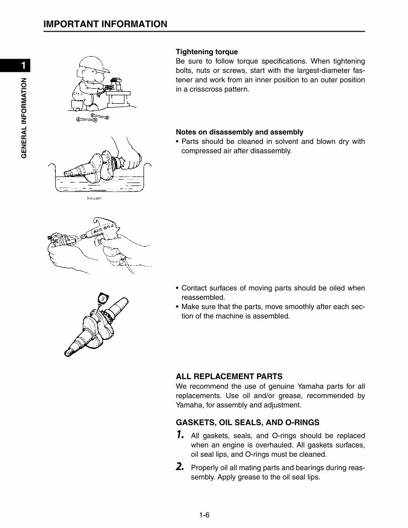
IMPORTANT INFORMATION
IMPORTANT INFORMATION
PREPARATION FOR REMOVAL AND DISASSEMBLY
CAUTION ON SERVICEFire preventionWhen servicing the engine, always keep the engine andyourself away from fire.
NOTES ON SERVICECorrect toolsBe sure to use the correct special tool for the job to guardagainst damage.
Oil, grease and sealsBe sure to use genuine Yamaha oils, grease and sealers,or the equivalents.
Expendable partsAlways replace the gaskets, O-rings, cotter pins and cir-clips with new parts when servicing engine.
IMPORTANT INFORMATION
1-6
1
2
3
4
5
6
7
8
9
10
GE
NE
RA
L IN
FO
RM
AT
ION
Tightening torqueBe sure to follow torque specifications. When tighteningbolts, nuts or screws, start with the largest-diameter fas-tener and work from an inner position to an outer positionin a crisscross pattern.
Notes on disassembly and assembly• Parts should be cleaned in solvent and blown dry with
compressed air after disassembly.
• Contact surfaces of moving parts should be oiled whenreassembled.
• Make sure that the parts, move smoothly after each sec-tion of the machine is assembled.
ALL REPLACEMENT PARTSWe recommend the use of genuine Yamaha parts for allreplacements. Use oil and/or grease, recommended byYamaha, for assembly and adjustment.
GASKETS, OIL SEALS, AND O-RINGS
1. All gaskets, seals, and O-rings should be replacedwhen an engine is overhauled. All gaskets surfaces,oil seal lips, and O-rings must be cleaned.
2. Properly oil all mating parts and bearings during reas-sembly. Apply grease to the oil seal lips.
1-7
1
2
3
4
5
6
7
8
9
10
GE
NE
RA
L IN
FO
RM
AT
ION
BASIC SERVICE INFORMATION
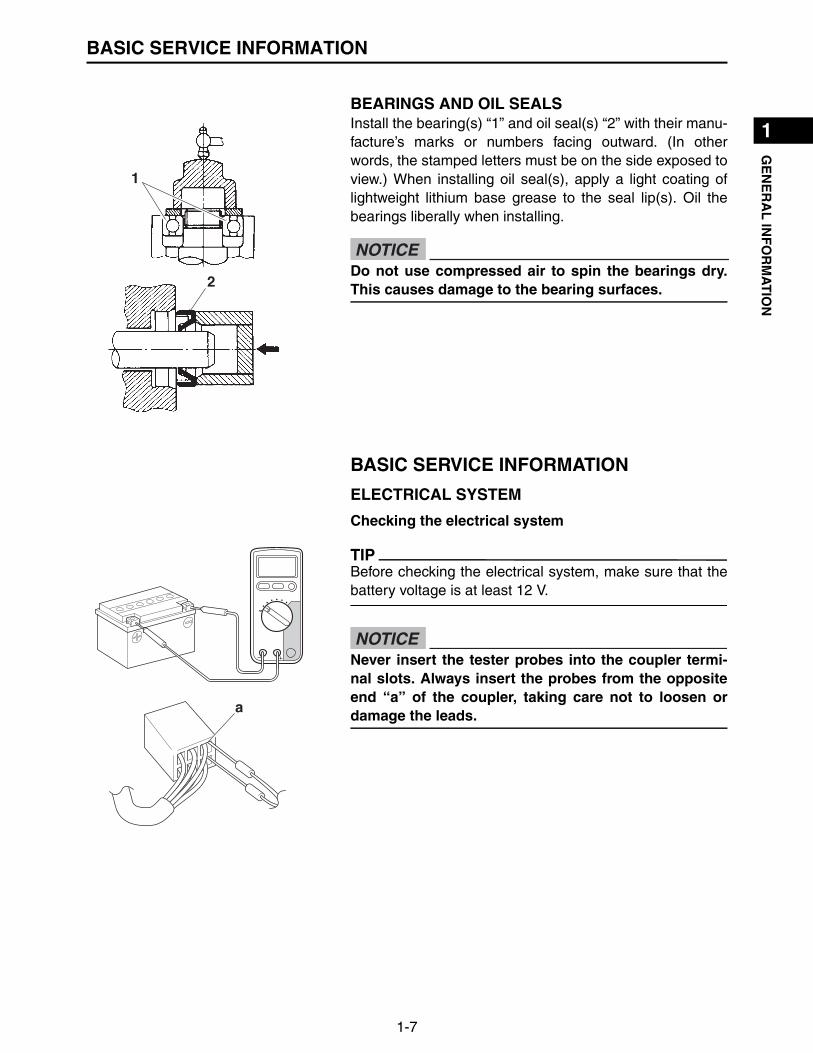
BEARINGS AND OIL SEALSInstall the bearing(s) “1” and oil seal(s) “2” with their manu-facture’s marks or numbers facing outward. (In otherwords, the stamped letters must be on the side exposed toview.) When installing oil seal(s), apply a light coating oflightweight lithium base grease to the seal lip(s). Oil thebearings liberally when installing.
BASIC SERVICE INFORMATION
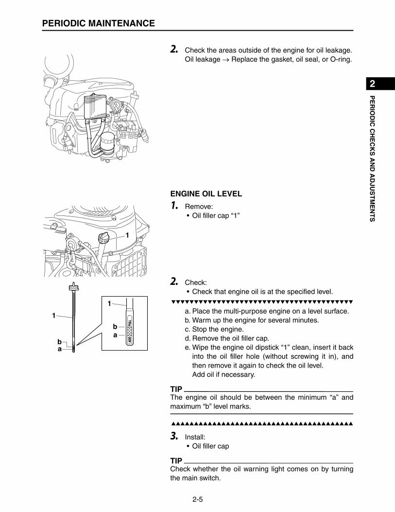
ELECTRICAL SYSTEM
Checking the electrical system
TIP
Before checking the electrical system, make sure that thebattery voltage is at least 12 V.
1
2Do not use compressed air to spin the bearings dry.This causes damage to the bearing surfaces.
NOTICE
a
Never insert the tester probes into the coupler termi-nal slots. Always insert the probes from the oppositeend “a” of the coupler, taking care not to loosen ordamage the leads.
NOTICE

BASIC SERVICE INFORMATION
1-8
1
2
3
4
5
6
7
8
9
10
GE
NE
RA
L IN
FO
RM
AT
ION
Checking the connections
Check the leads, couplers, and connectors for stains, rust,moisture, etc.
1. Disconnect:• Lead• Coupler• Connector
2. Check:• Lead• Coupler• Connector
Moisture Dry with an air blower.Rust/stains Connect and disconnect severaltimes.
• When disconnecting a coupler, release the couplerlock, hold both sections of the coupler securely, andthen disconnect the coupler.
• There are many types of coupler locks; therefore, besure to check the type of coupler lock before discon-necting the coupler.
NOTICE
When disconnecting a connector, do not pull theleads. Hold both sections of the connector securely,and then disconnect the connector.
NOTICE

1-9
1
2
3
4
5
6
7
8
9
10
GE
NE
RA
L IN
FO
RM
AT
ION
BASIC SERVICE INFORMATION
3. Connect:• Lead• Coupler• Connector
TIP
• When connecting a coupler or connector, push both sec-tions of the coupler or connector together until they areconnected securely.
• Make sure all connections are tight.
4. Check:• Continuity
(with the digital circuit tester)
TIP
• If there is no continuity, clean the terminals.• When checking the wire harness, perform steps (1) to
(3).• As a quick remedy, use a contact revitalizer available at
most part stores.
Model 88 Multimeter with tachometer:YU-A1927
For waterproof couplers, never insert the tester leadsdirectly into the coupler. When performing any checksusing a waterproof coupler, use the specified test har-ness or a suitable commercially available test harness.
NOTICE

BASIC SERVICE INFORMATION
1-10
1
2
3
4
5
6
7
8
9
10
GE
NE
RA
L IN
FO
RM
AT
ION
5. Check:• Resistance
TIP
The resistance values shown were obtained at the stan-dard measuring temperature of 20 C (68 F). If the mea-suring temperature is not 20 C (68 F), the specifiedmeasuring conditions will be shown.
Model 88 Multimeter with tachometer:YU-A1927
Engine temperature sensor resistance:9.0 k–11.0 k at 25 C (77 F)

1-11
1
2
3
4
5
6
7
8
9
10
GE
NE
RA
L IN
FO
RM
AT
ION
SPECIAL TOOLS AND TESTERS
SPECIAL TOOLS AND TESTERS
The proper special tools are necessary for complete and accurate tune-up and assembly. Using thecorrect special tool will help prevent damage caused by the use of improper tools or improvisedtechniques.
Valve spring compressor90890-01253
Ignition checker90890-06754
FI Diagnostic Tool90890-03253
Feeler gauge setYU-26900-9
Oil filter wrenchYM-01469
Engine compression tes-terYU-33223
Primary clutch holderYU-01235
Rotor holding tool90890-01235
Heavy duty pullerYU-33270-B
Cylinder gaugeCommercially obtainable
Piston ring compressorYM-08037
Dial indicator gaugeYU-A8428
Pressure/vacuum testerYB-35956-B
Fuel pressure gaugeYU-03153
Fuel pressure adapterYM-03186
Model 88 Multimeter with tachometerYU-A1927
66.8
YU-33223
SVU1160

SPECIAL TOOLS AND TESTERS
1-12
1
2
3
4
5
6
7
8
9
10
GE
NE
RA
L IN
FO
RM
AT
ION
MEMO

1
2
3
4
5
6
7
8
9
10
PE
RIO
DIC
CH
EC
KS
AN
D A
DJU
ST
ME
NT
S
2-1
PERIODIC CHECKS AND ADJUSTMENTSINTRODUCTION
This chapter includes all information necessary to perform recommended checks and adjustments.These preventive maintenance procedures, if followed, will ensure more reliable machine operationand a longer service life. The need for costly overhaul work will be greatly reduced. This informationapplies to machines already in service as well as new machines that are being prepared for sale. Allservice technicians should be familiar with this entire chapter.
MAINTENANCE INTERVALS CHART
Proper periodic maintenance is important. Especially important are the maintenance servicesrelated to emissions control. These controls not only function to ensure air filter but are also vital toproper engine operation and maximum performance.
PERIODIC MAINTENANCE/LUBRICATION INTERVALS
*1 For models equipped with a Yamaha muffler.*2 Items marked with an asterisk require special tools, data and technical skills, have a Yamahadealer perform the service.
Daily 50 hrs100 hrs
200 hrs
250 hrs
500 hrs
1000 hrs
Check spark plug
Check muffler and spark arrester (*1)
Check oil level
Change engine oil
Change oil filter
Clean fan case covers and cooling area
Check and change fuel filter
Check fuel line
Clean oil cooler fins
Check air filter element
Replace air filter element
Check air filter inner element
Replace air filter inner element
Check valve clearance (*2)
Clean combustion chamber (*2)
Idle speed (*2)
Fitting/fastener (*2)
Check leaks and anything operator notices such as noises or abnormal operation.

2-2
1
2
3
4
5
6
7
8
9
10
PE
RIO
DIC
CH
EC
KS
AN
D A
DJU
ST
ME
NT
SPERIODIC MAINTENANCE
PERIODIC MAINTENANCE
SPARK PLUGS
1. Remove:• Spark plug caps “1”• Spark plugs
2. Check:• Spark plug type
Not correct Replace.
• Electrode “1”Wear/damage Replace.
• Insulator color “2”Not normal Replace.
3. Measure:• Spark plug gap “a”
Use a wire gauge or feeler gauge set.Out of specification Regap.If necessary, clean the spark plugs with a sparkplug cleaner.
TIP
Before installing the spark plugs, clean the gasket surfaceand plug surface.
Check and adjust the areas around the cylinder headafter the engine has cooled down completely.
WARNING
Before removing the spark plugs, use compressed airto clean the cylinder head covers to prevent dirt fromfalling into the engine.
NOTICE
12
a
Spark plug type:BPR6ES (NGK)
Feeler gauge set:YU-26900-9
Spark plug gap:0.7–0.8 mm (0.028–0.031 in)

2-3
1
2
3
4
5
6
7
8
9
10
PE
RIO
DIC
CH
EC
KS
AN
D A
DJU
ST
ME
NT
SPERIODIC MAINTENANCE
4. Install:• Spark plugs
TIP
To prevent threads from being damaged, temporallytighten “a” the spark plug before tightening it to the speci-fied torque “b”.
MUFFLER (For models equipped with a muffler)
1. Remove:• Spark arrester screw “1”
2. Remove:• Spark arrester “1”
TIP
Use a flathead screw driver to pry the spark arrester outfrom the muffler.
a
b
Spark plug:20 N·m (2.0 kgf·m, 14 lb·ft)T
R..
The engine and muffler will be very hot after theengine has been run.Avoid touching the engine and muffler while they arestill hot with any part of your body or clothing duringcheck or repair.
WARNING

2-4
1
2
3
4
5
6
7
8
9
10
PE
RIO
DIC
CH
EC
KS
AN
D A
DJU
ST
ME
NT
SPERIODIC MAINTENANCE
3. Remove:• Muffler
(Refer to “MUFFLER (For models equipped with amuffler)” on page 3-4)
4. Decarbonize:• Muffler
Tap on the muffler in the area shown in the illustra-tion to loosen carbon buildup, and then shake it outfrom the end of the muffler.
5. Decarbonize:• Spark arrester
6. Install:• Muffler
(Refer to “MUFFLER (For models equipped with amuffler)” on page 3-4)
• Spark arrester• Spark arrester screw
TIP
Align the spark arrester lump “a” with the hole “b” in themuffler pipe.
ENGINE OIL LEAKAGE
1. Place the multi-purpose engine on a level surface.
Do not use a wire brush to clean, otherwise the noisedamping material may come out, and the dampingeffect may be reduced.
NOTICE
When cleaning with a wire brush, use it softly to avoiddamage or scratch the spark arrester.
NOTICE
Spark arrester screw:3.5 N·m (0.35 kgf·m, 2.5 lb·ft)T
R..
2-5
1
2
3
4
5
6
7
8
9
10
PE
RIO
DIC
CH
EC
KS
AN
D A
DJU
ST
ME
NT
SPERIODIC MAINTENANCE
2. Check the areas outside of the engine for oil leakage.Oil leakage Replace the gasket, oil seal, or O-ring.
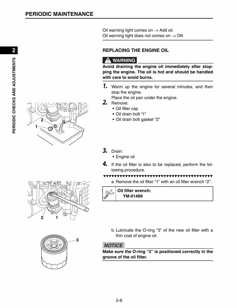
ENGINE OIL LEVEL
1. Remove:• Oil filler cap “1”
2. Check:• Check that engine oil is at the specified level.
▼▼▼▼▼▼▼▼▼▼▼▼▼▼▼▼▼▼▼▼▼▼▼▼▼▼▼▼▼▼▼▼▼▼▼▼▼▼▼▼▼
a. Place the multi-purpose engine on a level surface.b. Warm up the engine for several minutes.c. Stop the engine.d. Remove the oil filler cap.e. Wipe the engine oil dipstick “1” clean, insert it back
into the oil filler hole (without screwing it in), andthen remove it again to check the oil level. Add oil if necessary.
TIP
The engine oil should be between the minimum “a” andmaximum “b” level marks.
▲▲▲▲▲▲▲▲▲▲▲▲▲▲▲▲▲▲▲▲▲▲▲▲▲▲▲▲▲▲▲▲▲▲▲▲▲▲▲▲▲
3. Install:• Oil filler cap
TIP
Check whether the oil warning light comes on by turningthe main switch.
2-6
1
2
3
4
5
6
7
8
9
10
PE
RIO
DIC
CH
EC
KS
AN
D A
DJU
ST
ME
NT
SPERIODIC MAINTENANCE
Oil warning light comes on Add oil.Oil warning light does not comes on OK
REPLACING THE ENGINE OIL
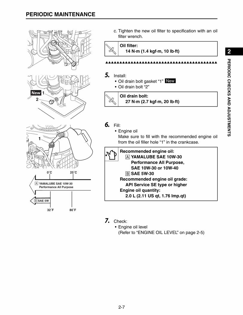
1. Warm up the engine for several minutes, and thenstop the engine.Place the oil pan under the engine.
2. Remove:• Oil filler cap• Oil drain bolt “1”• Oil drain bolt gasket “2”
3. Drain:• Engine oil
4. If the oil filter is also to be replaced, perform the fol-lowing procedure.
▼▼▼▼▼▼▼▼▼▼▼▼▼▼▼▼▼▼▼▼▼▼▼▼▼▼▼▼▼▼▼▼▼▼▼▼▼▼▼▼▼
a. Remove the oil filter “1” with an oil filter wrench “2”.
b. Lubricate the O-ring “3” of the new oil filter with athin coat of engine oil.
Avoid draining the engine oil immediately after stop-ping the engine. The oil is hot and should be handledwith care to avoid burns.
WARNING
2 1
Oil filter wrench:YM-01469
Make sure the O-ring “3” is positioned correctly in thegroove of the oil filter.
NOTICE
2-7
1
2
3
4
5
6
7
8
9
10
PE
RIO
DIC
CH
EC
KS
AN
D A
DJU
ST
ME
NT
SPERIODIC MAINTENANCE
c. Tighten the new oil filter to specification with an oilfilter wrench.
▲▲▲▲▲▲▲▲▲▲▲▲▲▲▲▲▲▲▲▲▲▲▲▲▲▲▲▲▲▲▲▲▲▲▲▲▲▲▲▲▲
5. Install:• Oil drain bolt gasket “1” • Oil drain bolt “2”
6. Fill:• Engine oil
Make sure to fill with the recommended engine oilfrom the oil filler hole “1” in the crankcase.
7. Check:• Engine oil level
(Refer to “ENGINE OIL LEVEL” on page 2-5)
Oil filter:14 N·m (1.4 kgf·m, 10 lb·ft)T
R..
21
Oil drain bolt:27 N·m (2.7 kgf·m, 20 lb·ft)
New
TR..
0˚C
SAE 5W
32˚F
25˚C
80˚F
YAMALUBE SAE 10W-30Performance All Purpose
Recommended engine oil:A YAMALUBE SAE 10W-30
Performance All Purpose, SAE 10W-30 or 10W-40
B SAE 5W-30Recommended engine oil grade:
API Service SE type or higherEngine oil quantity:
2.0 L (2.11 US qt, 1.76 Imp.qt)
2-8
1
2
3
4
5
6
7
8
9
10
PE
RIO
DIC
CH
EC
KS
AN
D A
DJU
ST
ME
NT
SPERIODIC MAINTENANCE
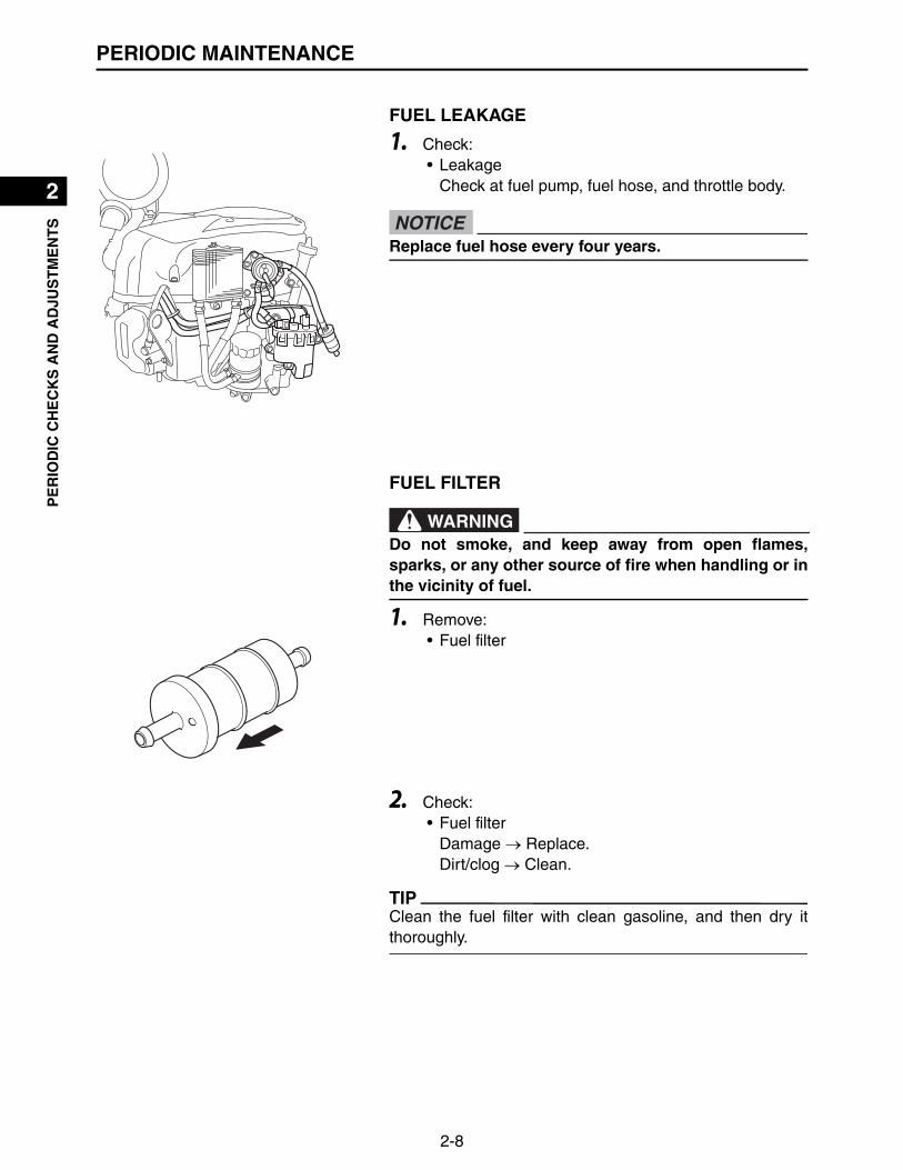
FUEL LEAKAGE
1. Check:• Leakage
Check at fuel pump, fuel hose, and throttle body.
FUEL FILTER
1. Remove:• Fuel filter
2. Check:• Fuel filter
Damage Replace.Dirt/clog Clean.
TIP
Clean the fuel filter with clean gasoline, and then dry itthoroughly.
Replace fuel hose every four years.NOTICE
Do not smoke, and keep away from open flames,sparks, or any other source of fire when handling or inthe vicinity of fuel.
WARNING

2-9
1
2
3
4
5
6
7
8
9
10
PE
RIO
DIC
CH
EC
KS
AN
D A
DJU
ST
ME
NT
SPERIODIC MAINTENANCE
OIL COOLER
1. Check:• Oil cooler
Damage Replace.Dirt/clog Clean.
AIR FILTER ELEMENT
1. Remove:• Dust cap “1”• Air filter case cover “2”• Air filter element “3”• Inner element “4”
2. Check:• Air filter element• Inner element
Damage/dirty Replace.
3. Install:• Inner element• Air filter element• Air filter case cover• Dust cap
ADJUSTING THE VALVE CLEARANCEThe following procedure applies to all of the valves.
1. Remove:• Spark plug cap “1”• Spark plug “2”
Be sure not to run the engine without air filter element.Otherwise this can result in excessive piston and/orcylinder wear.
NOTICE
1
2
3
Before removing the spark plug, use compressed airto clean the cylinder head cover to prevent dirt fromfalling into the engine.
NOTICE

2-10
1
2
3
4
5
6
7
8
9
10
PE
RIO
DIC
CH
EC
KS
AN
D A
DJU
ST
ME
NT
SPERIODIC MAINTENANCE
2. Remove:• Cylinder head cover “3”• Cylinder head cover gasket
3. Remove:• Fan case cover “1”
(Refer to “CASE AND FAN” on page 3-11)• Grass screen “2”
(Refer to “CASE AND FAN” on page 3-11)
4. Turn the crankshaft clockwise, and then set the pistonat TDC (top-dead-center) on the compression stroke.
TIP
Check the piston position by inserting a screw driver intothe spark plug hole.
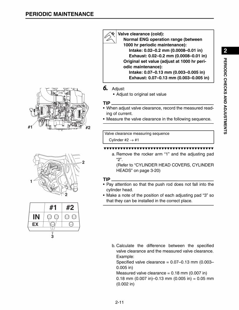
5. Measure:• Valve clearance
(Between the rocker arm and adjusting pad)Out of specification Adjust to original set value atevery 1000 hr.
TIP
Valve clearance must be measured when the engine hascooled down enough to be touched.
1
2
Feeler gauge set:YU-26900-9
2-11
1
2
3
4
5
6
7
8
9
10
PE
RIO
DIC
CH
EC
KS
AN
D A
DJU
ST
ME
NT
SPERIODIC MAINTENANCE
6. Adjust:• Adjust to original set value
TIP
• When adjust valve clearance, record the measured read-ing of current.
• Measure the valve clearance in the following sequence.
▼▼▼▼▼▼▼▼▼▼▼▼▼▼▼▼▼▼▼▼▼▼▼▼▼▼▼▼▼▼▼▼▼▼▼▼▼▼▼▼▼
a. Remove the rocker arm “1” and the adjusting pad“2”.(Refer to “CYLINDER HEAD COVERS, CYLINDERHEADS” on page 3-20)
TIP
• Pay attention so that the push rod does not fall into thecylinder head.
• Make a note of the position of each adjusting pad “3” sothat they can be installed in the correct place.
b. Calculate the difference between the specifiedvalve clearance and the measured valve clearance.Example:Specified valve clearance = 0.07–0.13 mm (0.003–0.005 in)Measured valve clearance = 0.18 mm (0.007 in)0.18 mm (0.007 in)–0.13 mm (0.005 in) = 0.05 mm(0.002 in)
Valve clearance (cold):Normal ENG operation range (between 1000 hr periodic maintenance):
Intake: 0.02–0.2 mm (0.0008–0.01 in)Exhaust: 0.02–0.2 mm (0.0008–0.01 in)
Original set value (adjust at 1000 hr peri-odic maintenance):
Intake: 0.07–0.13 mm (0.003–0.005 in)Exhaust: 0.07–0.13 mm (0.003–0.005 in)
#1 #2Valve clearance measuring sequence
Cylinder #2 #1
1
2
2
3
2-12
1
2
3
4
5
6
7
8
9
10
PE
RIO
DIC
CH
EC
KS
AN
D A
DJU
ST
ME
NT
SPERIODIC MAINTENANCE
c. Check the thickness of the current adjusting pad.
TIP
The thickness of each adjusting pad is indicated in 1/100mm units “a” and inscribed on the side.
Example:If the adjusting pad is marked “180”, the pad thick-ness is 1.80 mm (0.071 in).
d. Calculate the sum of the values obtained in steps(b) and (c) to determine the required adjusting padthickness and the adjusting pad number.Example:1.80 mm (0.071 in) + 0.05 mm (0.002 in) = 1.85 mm(0.073 in)The adjusting pad number is 185.
e. Round off the adjusting pad number according tothe following table, and then select the suitableadjusting pad.
TIP
Refer to the following table for the available adjusting pads.
Example:Adjusting pad number = 188Rounded value = 200New adjusting pad number = 200
f. Install the new adjusting pad “4”.
TIP
Lubricate the adjusting pad with engine oil.
a
Last digit Rounded value
0,2 0
5 5
8 10
Adjusting pad range Nos. 180–300
Adjusting pad thickness1.80–3.00 mm(0.07086–0.11811 in)
Available adjusting pads0.050 mm (0.002 in) incre-ments
4
4
2-13
1
2
3
4
5
6
7
8
9
10
PE
RIO
DIC
CH
EC
KS
AN
D A
DJU
ST
ME
NT
SPERIODIC MAINTENANCE
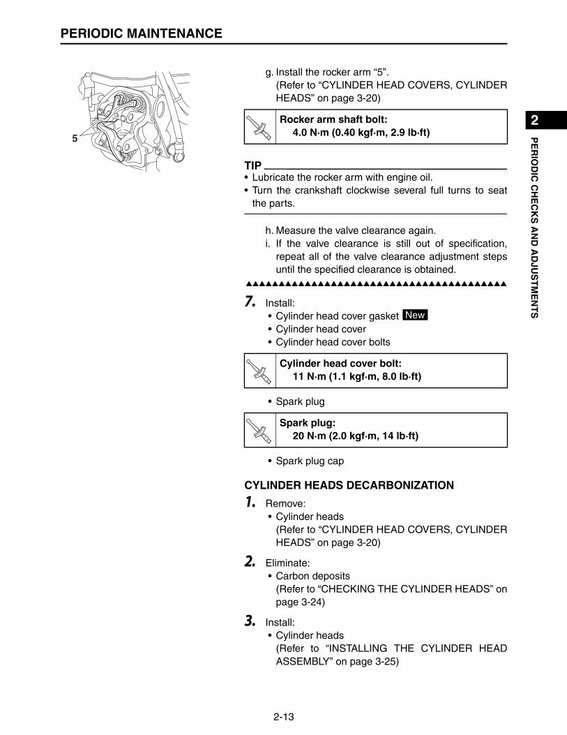
g. Install the rocker arm “5”.(Refer to “CYLINDER HEAD COVERS, CYLINDERHEADS” on page 3-20)
TIP
• Lubricate the rocker arm with engine oil.• Turn the crankshaft clockwise several full turns to seat
the parts.
h. Measure the valve clearance again.i. If the valve clearance is still out of specification,
repeat all of the valve clearance adjustment stepsuntil the specified clearance is obtained.
▲▲▲▲▲▲▲▲▲▲▲▲▲▲▲▲▲▲▲▲▲▲▲▲▲▲▲▲▲▲▲▲▲▲▲▲▲▲▲▲▲
7. Install:• Cylinder head cover gasket • Cylinder head cover• Cylinder head cover bolts
• Spark plug
• Spark plug cap
CYLINDER HEADS DECARBONIZATION
1. Remove:• Cylinder heads
(Refer to “CYLINDER HEAD COVERS, CYLINDERHEADS” on page 3-20)
2. Eliminate:• Carbon deposits
(Refer to “CHECKING THE CYLINDER HEADS” onpage 3-24)
3. Install:• Cylinder heads
(Refer to “INSTALLING THE CYLINDER HEADASSEMBLY” on page 3-25)
5
Rocker arm shaft bolt:4.0 N·m (0.40 kgf·m, 2.9 lb·ft)T
R..
Cylinder head cover bolt:11 N·m (1.1 kgf·m, 8.0 lb·ft)
Spark plug:20 N·m (2.0 kgf·m, 14 lb·ft)
New
TR..
TR..

2-14
1
2
3
4
5
6
7
8
9
10
PE
RIO
DIC
CH
EC
KS
AN
D A
DJU
ST
ME
NT
SPERIODIC MAINTENANCE
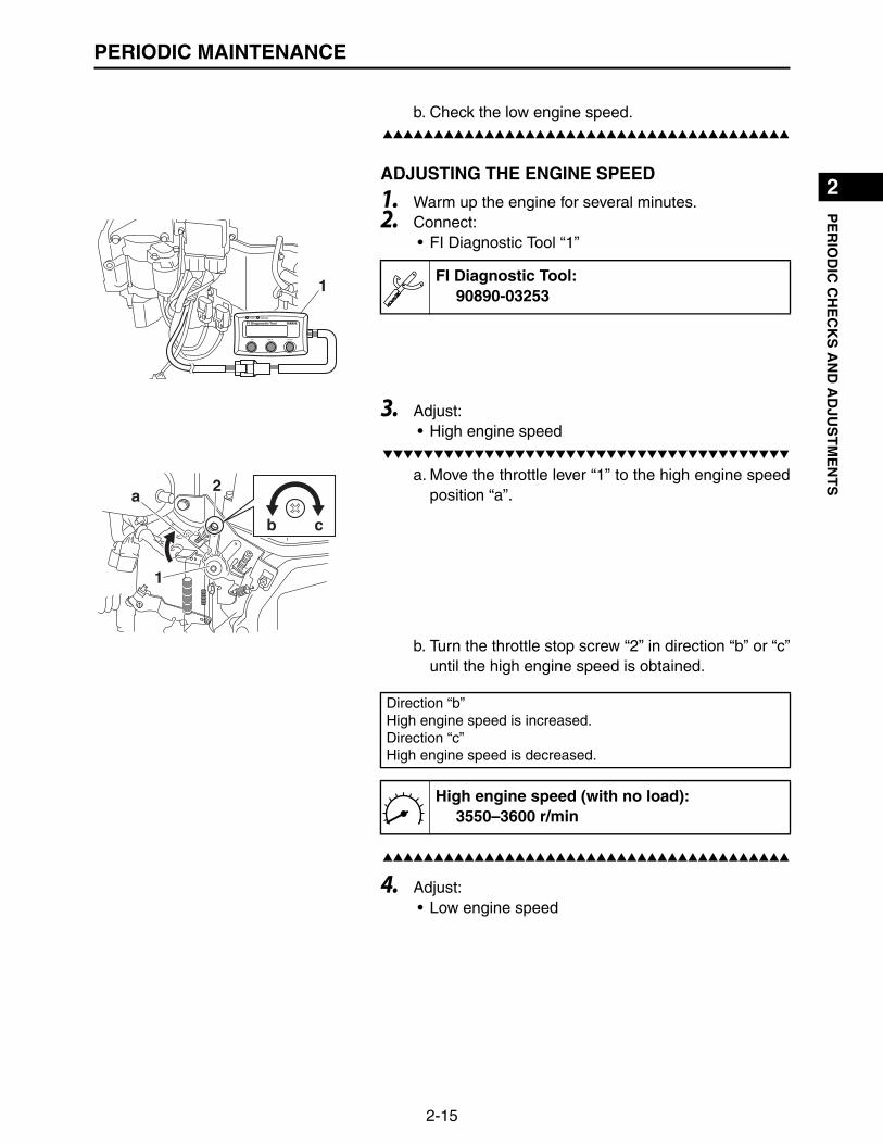
ENGINE SPEED
1. Warm up the engine for several minutes.2. Connect:
• FI Diagnostic Tool “1”
3. Measure:• High engine speed (with no load)
Out of specification Adjust.
▼▼▼▼▼▼▼▼▼▼▼▼▼▼▼▼▼▼▼▼▼▼▼▼▼▼▼▼▼▼▼▼▼▼▼▼▼▼▼▼▼
a. Move the throttle lever “1” to the high engine speedposition “a”.
b. Check the high engine speed.▲▲▲▲▲▲▲▲▲▲▲▲▲▲▲▲▲▲▲▲▲▲▲▲▲▲▲▲▲▲▲▲▲▲▲▲▲▲▲▲▲
4. Measure:• Low engine speed (with no load)
Out of specification Adjust.
▼▼▼▼▼▼▼▼▼▼▼▼▼▼▼▼▼▼▼▼▼▼▼▼▼▼▼▼▼▼▼▼▼▼▼▼▼▼▼▼▼
a. Move the throttle lever “1” to the low engine speedposition “a”.
1FI Diagnostic Tool:
90890-03253
High engine speed (with no load):3550–3600 r/min
a
1
Low engine speed (with no load):1450–1550 r/min
a
1
2-15
1
2
3
4
5
6
7
8
9
10
PE
RIO
DIC
CH
EC
KS
AN
D A
DJU
ST
ME
NT
SPERIODIC MAINTENANCE
b. Check the low engine speed.▲▲▲▲▲▲▲▲▲▲▲▲▲▲▲▲▲▲▲▲▲▲▲▲▲▲▲▲▲▲▲▲▲▲▲▲▲▲▲▲▲
ADJUSTING THE ENGINE SPEED
1. Warm up the engine for several minutes.2. Connect:
• FI Diagnostic Tool “1”
3. Adjust:• High engine speed
▼▼▼▼▼▼▼▼▼▼▼▼▼▼▼▼▼▼▼▼▼▼▼▼▼▼▼▼▼▼▼▼▼▼▼▼▼▼▼▼▼
a. Move the throttle lever “1” to the high engine speedposition “a”.
b. Turn the throttle stop screw “2” in direction “b” or “c”until the high engine speed is obtained.
▲▲▲▲▲▲▲▲▲▲▲▲▲▲▲▲▲▲▲▲▲▲▲▲▲▲▲▲▲▲▲▲▲▲▲▲▲▲▲▲▲
4. Adjust:• Low engine speed
1FI Diagnostic Tool:
90890-03253
1
2 a
b c
Direction “b”High engine speed is increased.Direction “c”High engine speed is decreased.
High engine speed (with no load):3550–3600 r/min

2-16
1
2
3
4
5
6
7
8
9
10
PE
RIO
DIC
CH
EC
KS
AN
D A
DJU
ST
ME
NT
SPERIODIC MAINTENANCE
▼▼▼▼▼▼▼▼▼▼▼▼▼▼▼▼▼▼▼▼▼▼▼▼▼▼▼▼▼▼▼▼▼▼▼▼▼▼▼▼▼
a. Move the throttle lever “1” to the low engine speedposition “a”.
b. Turn the screw “3” in direction “c” or “d” until obtainadequet low engine speed.
▲▲▲▲▲▲▲▲▲▲▲▲▲▲▲▲▲▲▲▲▲▲▲▲▲▲▲▲▲▲▲▲▲▲▲▲▲▲▲▲▲
LOW ENGINE SPEED (Replace the throttle body)
TIP
When replace throttle body, follow the procedure below.Adjust low engine speed with throttle stop screw “1” indirection “a” or “b”.
1. Turn the throttle stop screw “1” (throttle body) in direc-tion “a” or “b” until the low engine speed is obtained.
FITTINGS AND FASTENERS
1. Check:• All fittings and fasteners
Looseness Tighten.Rough movement Replace the defective part(s).Damage/pitting Replace.
a
1
c db
3
22 Direction “c”Low engine speed is decreased.Direction “d”Low engine speed is increased.
Low engine speed (with no load):1450–1550 r/min
1
a b
Direction “a”Low engine speed is decreased.Direction “b”Low engine speed is increased.
Low engine speed (with no load):1450–1550 r/min

1
2
3
4
5
6
7
8
9
10
EN
GIN
E
3-1
ENGINEENGINE INSPECTION
MEASURING THE COMPRESSION PRESSUREThe following procedure applies to all of the cylinders.
TIP
Measure the compression pressure after checking andadjusting the valve clearance.
1. Warm up the engine for several minutes.
2. Remove:• Spark plug cap• Spark plug
3. Connect:• Engine compression tester “1”• Extension “2”
4. Measure:• Compression pressure
Open the throttle and crank the engine until theneedle stop rising on the engine compression tes-ter.Out of specification Refer to steps (a) and (b).
Before removing the spark plug, use compressed airto clean the cylinder head cover to prevent dirt fromfalling into the engine.
NOTICE
1
2
Engine compression tester:YU-33223
Standard compression pressure:1.31–1.45 MPa (13.4–14.8 kg/cm², 190–210 psi)
Limit:1.03 MPa (10.3 kg/cm², 150 psi)
To prevent sparking the plugs, remove all ignition coilcouplers and fuel injector couplers before crankingthe engine.
WARNING
3-2
1
2
3
4
5
6
7
8
9
10
EN
GIN
EENGINE INSPECTION
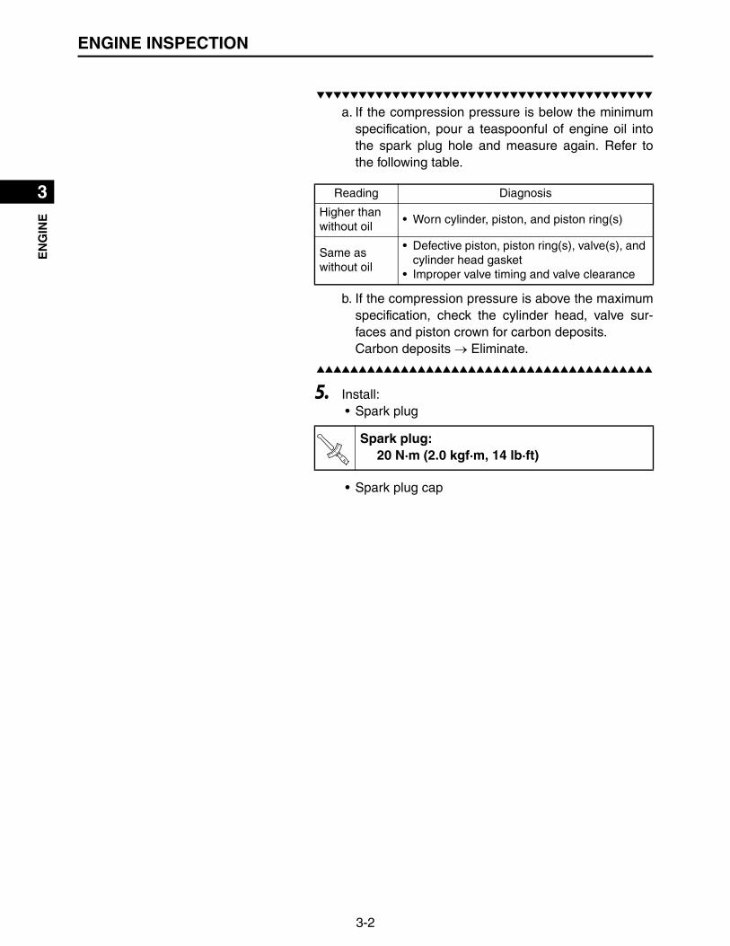
▼▼▼▼▼▼▼▼▼▼▼▼▼▼▼▼▼▼▼▼▼▼▼▼▼▼▼▼▼▼▼▼▼▼▼▼▼▼▼▼▼
a. If the compression pressure is below the minimumspecification, pour a teaspoonful of engine oil intothe spark plug hole and measure again. Refer tothe following table.
b. If the compression pressure is above the maximumspecification, check the cylinder head, valve sur-faces and piston crown for carbon deposits.Carbon deposits Eliminate.
▲▲▲▲▲▲▲▲▲▲▲▲▲▲▲▲▲▲▲▲▲▲▲▲▲▲▲▲▲▲▲▲▲▲▲▲▲▲▲▲▲
5. Install:• Spark plug
• Spark plug cap
Reading Diagnosis
Higher than without oil
• Worn cylinder, piston, and piston ring(s)
Same as without oil
• Defective piston, piston ring(s), valve(s), and cylinder head gasket
• Improper valve timing and valve clearance
Spark plug:20 N·m (2.0 kgf·m, 14 lb·ft)T
R..

3-3
1
2
3
4
5
6
7
8
9
10
EN
GIN
EAIR FILTER
AIR FILTER
Order Job/Parts to remove Q’ty Remarks
Removing the air filter Remove the parts in the order listed.
1 Dust cap 1
2 Air filter case cover 1
3 Air filter element 1
4 Inner element 1
5 Air filter cover 1 1
6 Air filter case stay 1
7 Air filter case 1
8 Joint 2 1
1
2
3
4
5
6
6
7
8
10 N・m (1.0 kgf・m, 7.2 lb・ft)
1.8 N・m (0.18 kgf・m, 1.3 lb・ft)
1.8 N・m (0.18 kgf・m, 1.3 lb・ft)
7 N・m (0.7 kgf・m, 5.1 lb・ft)
3-4
1
2
3
4
5
6
7
8
9
10
EN
GIN
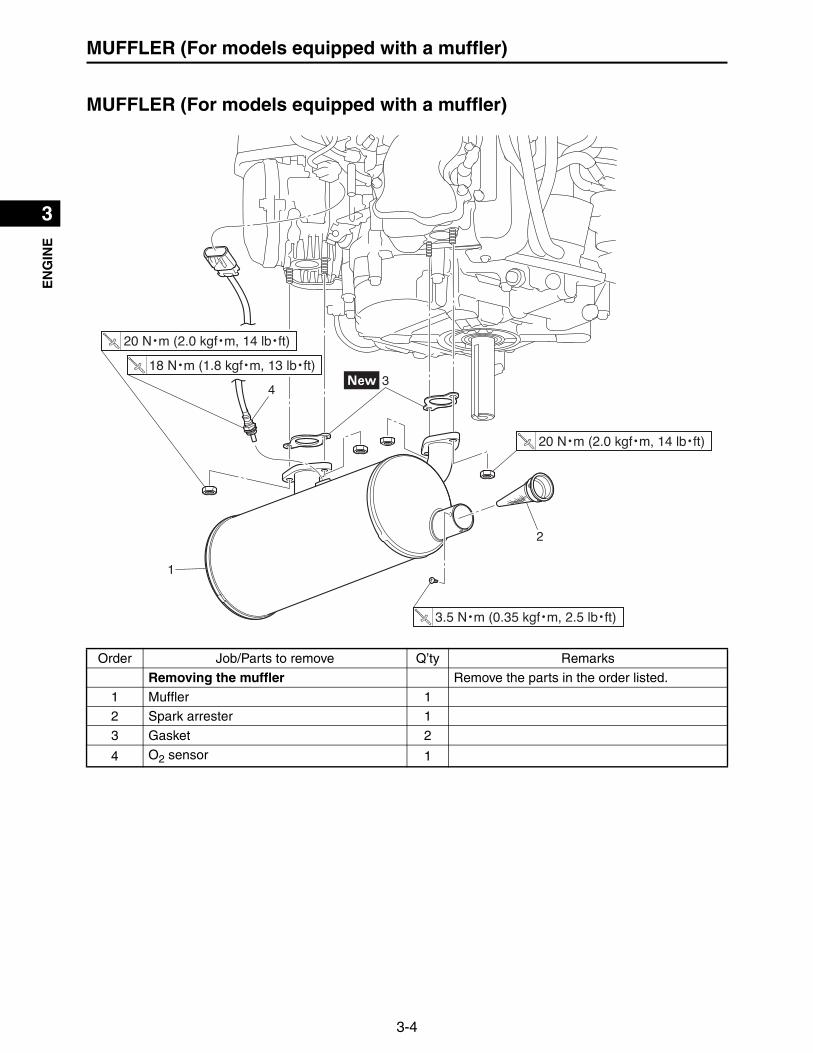
EMUFFLER (For models equipped with a muffler)
MUFFLER (For models equipped with a muffler)
Order Job/Parts to remove Q’ty Remarks
Removing the muffler Remove the parts in the order listed.
1 Muffler 1
2 Spark arrester 1
3 Gasket 2
4 O2 sensor 1
1
2
3
3.5 N・m (0.35 kgf・m, 2.5 lb・ft)
20 N・m (2.0 kgf・m, 14 lb・ft)
20 N・m (2.0 kgf・m, 14 lb・ft)
18 N・m (1.8 kgf・m, 13 lb・ft)
4

3-5
1
2
3
4
5
6
7
8
9
10
EN
GIN
EOIL COOLER
OIL COOLER
Order Job/Parts to remove Q’ty Remarks
Removing the oil cooler Remove the parts in the order listed.
Engine oilDrain.Refer to “REPLACING THE ENGINE OIL” on page 2-6.
1 Oil cooler 1
2 Oil hose 1 1
3 Oil hose 2 1
4 Oil filter 1
5 Adapter union bolt 1
6 Adapter 1
7 Oil seal 1
17 N・m (1.7 kgf・m, 12 lb・ft)
14 N・m (1.4 kgf・m, 10 lb・ft)
9 N・m (0.9 kgf・m, 6.5 lb・ft)
62 N・m (6.2 kgf・m, 45 lb・ft)
1
2
3
4
5
6
7

3-6
1
2
3
4
5
6
7
8
9
10
EN
GIN
EOIL COOLER
REMOVING THE OIL COOLER
1. Remove:• Hose clamp (Clic-R) “1”
TIP
• Remove the hose clamp using the hose clamp pliers “2”.• When removing the hose clamp, make sure that the thick
tip “a” of the hose clamp pliers is directed as shown inthe illustration.
2. Remove:• Oil hose 1• Oil hose 2• Oil cooler
CHECKING THE OIL COOLER
1. Check:• Oil cooler “1”• Oil hose 1 “2”• Oil hose 2 “3”• Adapter “4”
Damage Replace.Dirt/clog Clean.
INSTALLING THE OIL COOLER
1. Clean:• Mating surfaces of the adapter and the crankcase
cover 2(with a cloth dampened with lacquer thinner)
2. Install:• Oil seal “1” • Adapter “2”• Adapter union bolt “3”
1
2
a
A. Hose clamp pliers
12
3
4
1
2
3
Adapter union bolt:62 N·m (6.2 kgf·m, 45 lb·ft)
New
TR..

3-7
1
2
3
4
5
6
7
8
9
10
EN
GIN
EOIL COOLER
TIP
• Make sure the oil seal is positioned properly.• Align the projection “a” on the adapter with the hole “b” in
the crankcase cover 2.
3. Install:• Oil filter• Oil hose 2• Oil hose 1• Hose clamp (Clic-R) “1”
TIP
• Install the hose clamp using the hose clamp pliers “2”.• When installing the hose clamp, make sure that the thin
tip “a” of the hose clamp pliers is directed as shown inthe illustration.
4. Install:• Oil cooler• Oil cooler bolts
a
b
1 2
a
A. Hose clamp pliers
New
Oil cooler bolt:9 N·m (0.9 kgf·m, 6.5 lb·ft)T
R..

3-8
1
2
3
4
5
6
7
8
9
10
EN
GIN
EECU, RECTIFIER/REGULATOR, AND FUSES
ECU, RECTIFIER/REGULATOR, AND FUSES
Order Job/Parts to remove Q’ty Remarks
Removing the ECU, rectifier/regulator, and fuses
Remove the parts in the order listed.
1 ECU coupler 2 Disconnect.
2 Earth terminal 1
3 ECU 1
4 Engine hunger 1 For maintenance.
5 Rectifier/regulator lead connector 4 Disconnect.
6 Rectifier/regulator 1
7 Fuse holder bracket 1
8 Fuse 1 30 A
9 Fuse 2 10 A
20 N・m (2.0 kgf・m, 14 lb・ft)
4.0 N・m (0.40 kgf・m, 2.9 lb・ft)
7 N・m (0.7 kgf・m, 5.1 lb・ft)
7 N・m (0.7 kgf・m, 5.1 lb・ft)
7 N・m (0.7 kgf・m, 5.1 lb・ft)
1
2
3
4
5
6
7
89
3-9
1
2
3
4
5
6
7
8
9
10
EN
GIN
EECU, RECTIFIER/REGULATOR, AND FUSES
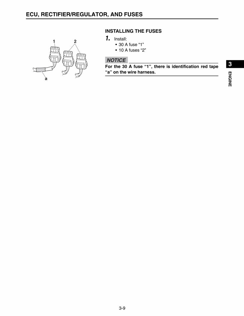
INSTALLING THE FUSES
1. Install:• 30 A fuse “1”• 10 A fuses “2”
21
a
For the 30 A fuse “1”, there is identification red tape“a” on the wire harness.
NOTICE

3-10
1
2
3
4
5
6
7
8
9
10
EN
GIN
EIGNITION COILS
IGNITION COILS
Order Job/Parts to remove Q’ty Remarks
Removing the ignition coils Remove the parts in the order listed.
Air filter case Refer to “AIR FILTER” on page 3-3.
ECU and rectifier/regulatorRefer to “ECU, RECTIFIER/REGULATOR, AND FUSES” on page 3-8.
Low-pressure fuel pump Refer to “FUEL PUMPS” on page 4-1.
Oil cooler Refer to “OIL COOLER” on page 3-5.
Fan case Refer to “CASE AND FAN” on page 3-11.
1 Ignition coil #1 lead coupler 1 Disconnect.
2 Ignition coil #2 lead coupler 1 Disconnect.
3 Ignition coil #1 1
4 Ignition coil #2 1
5 Spark plug 2
20 N・m (2.0 kgf・m, 14 lb・ft)
20 N・m (2.0 kgf・m, 14 lb・ft)
7 N・m (0.7 kgf・m, 5.1 lb・ft)
1 2
4
3
5
5

3-11
1
2
3
4
5
6
7
8
9
10
EN
GIN
ECASE AND FAN
CASE AND FAN
Order Job/Parts to remove Q’ty Remarks
Removing the case and fan Remove the parts in the order listed.
Air filter case Refer to “AIR FILTER” on page 3-3.
ECU and rectifier/regulatorRefer to “ECU, RECTIFIER/REGULATOR, AND FUSES” on page 3-8.
Low-pressure fuel pump Refer to “FUEL PUMPS” on page 4-1.
Oil cooler Refer to “OIL COOLER” on page 3-5.
1 Oil filler cap 1
2 Oil filler pipe 1
3 O-ring 1
4 Fan case cover 1
5 Grass screen 1
6 Fan case 1
7 Fan 1
10 N・m (1.0 kgf・m, 7.2 lb・ft)
10 N・m (1.0 kgf・m, 7.2 lb・ft)
10 N・m (1.0 kgf・m, 7.2 lb・ft)
7 N・m (0.7 kgf・m, 5.1 lb・ft)
7 N・m (0.7 kgf・m, 5.1 lb・ft) 7 N・m (0.7 kgf・m, 5.1 lb・ft)
1
2
3
4
5
6
710 N・m (1.0 kgf・m, 7.2 lb・ft)
(4)

3-12
1
2
3
4
5
6
7
8
9
10
EN
GIN
ECASE AND FAN
REMOVING THE CASE AND FAN
1. Remove:• Air filter case
(Refer to “AIR FILTER” on page 3-3)
2. Remove:• ECU and rectifier/regulator
(Refer to “ECU, RECTIFIER/REGULATOR, ANDFUSES” on page 3-8)
3. Remove:• Low-pressure fuel pump
(Refer to “FUEL PUMPS” on page 4-1)
4. Remove:• Oil cooler
(Refer to “OIL COOLER” on page 3-5)
5. Remove:• Oil filler cap• Oil filler pipe
6. Remove:• Fan case cover “1”• Grass screen “2”• Fan case “3”• Fan “4”
1
2
3
4
Because there is a risk of damage, remove the grassscreen “2” and fan case “3” in this order.
NOTICE

3-13
1
2
3
4
5
6
7
8
9
10
EN
GIN
ECASE AND FAN
CHECKING THE CASE AND FAN
1. Check:• Fan case cover “1”• Grass screen “2”• Fan case “3”• Fan “4”
Damage Replace.Dirt/clog Clean.
INSTALLING THE CASE AND FAN
1. Install:• Fan “1”• Fan bolts
• Fan case “2”• Fan case bolts
• Grass screen “3”• Grass screen bolts
• Fan case cover “4”• Fan case cover bolts
1
2
3
4
4
3
2
1
Fan bolt:10 N·m (1.0 kgf·m, 7.2 lb·ft)
Fan case bolt:7 N·m (0.7 kgf·m, 5.1 lb·ft)
Grass screen bolt:10 N·m (1.0 kgf·m, 7.2 lb·ft)
Fan case cover bolt:7 N·m (0.7 kgf·m, 5.1 lb·ft)
TR..
TR..
TR..
TR..

3-14
1
2
3
4
5
6
7
8
9
10
EN
GIN
ECASE AND FAN
TIP
Insert the tab “a” of the fan case cover “4” into the hole “b”of the fan case “2” first and then install.
2. Install:• Oil filler pipe • Oil filler pipe bolt
• Oil filler cap
24
a
b
ab
Oil filler pipe bolt:7 N·m (0.7 kgf·m, 5.1 lb·ft)T
R..

3-15
1
2
3
4
5
6
7
8
9
10
EN
GIN
EFLYWHEEL AND STATOR COIL ASSEMBLY
FLYWHEEL AND STATOR COIL ASSEMBLY
Order Job/Parts to remove Q’ty Remarks
Removing the flywheel and stator coil assembly
Remove the parts in the order listed.
Air filter case Refer to “AIR FILTER” on page 3-3.
ECU and rectifier/regulatorRefer to “ECU, RECTIFIER/REGULATOR, AND FUSES” on page 3-8.
Low-pressure fuel pump Refer to “FUEL PUMPS” on page 4-1.
Oil cooler Refer to “OIL COOLER” on page 3-5.
Fan case Refer to “CASE AND FAN” on page 3-11.
1 Crankshaft position sensor lead coupler 1 Disconnect.
2 Crankshaft position sensor 1
3 Flywheel 1
4 Woodruff key 1
5 Stator coil assembly 1
180 N・m (18 kgf・m, 130 lb・ft)
7 N・m (0.7 kgf・m, 5.1 lb・ft)
7 N・m (0.7 kgf・m, 5.1 lb・ft)
1
2
3
4
5

3-16
1
2
3
4
5
6
7
8
9
10
EN
GIN
EFLYWHEEL AND STATOR COIL ASSEMBLY
REMOVING THE FLYWHEEL AND STATOR COIL ASSEMBLY
1. Remove:• Air filter case
(Refer to “AIR FILTER” on page 3-3)
2. Remove:• ECU and rectifier/regulator
(Refer to “ECU, RECTIFIER/REGULATOR, ANDFUSES” on page 3-8)
3. Remove:• Low-pressure fuel pump
(Refer to “FUEL PUMPS” on page 4-1)
4. Remove:• Oil cooler
(Refer to “OIL COOLER” on page 3-5)
5. Remove:• Fan case cover• Grass screen• Fan case• Fan
(Refer to “CASE AND FAN” on page 3-11)
6. Remove:• Crankshaft position sensor “1”
7. Remove:• Flywheel nut “1”• Washer “2”
TIP
Attach the primary clutch holder “3” to hold the flywheel.
1
1
3
2
Primary clutch holder:YU-01235
Rotor holding tool:90890-01235

3-17
1
2
3
4
5
6
7
8
9
10
EN
GIN
EFLYWHEEL AND STATOR COIL ASSEMBLY
8. Remove:• Flywheel “1”• Woodruff key
TIP
• Remove the flywheel “1” using the heavy duty puller “2”.• Fully tighten the tool holding bolts, making sure the tool
body is parallel with the flywheel. If necessary, one boltmay be backed out slightly to level the tool body.
9. Remove:• Stator coil assembly
CHECKING THE FLYWHEEL AND STATOR COIL ASSEMBLY
1. Check:• Flywheel “1”• Stator coil assembly “2”
Damage Replace.
INSTALLING THE FLYWHEEL AND STATOR COIL ASSEMBLY
1. Install:• Stator coil assembly• Stator coil assembly bolts
2. Install:• Woodruff key• Flywheel
12
Heavy duty puller:YU-33270-B
1 2
Stator coil assembly bolt:7 N·m (0.7 kgf·m, 5.1 lb·ft)T
R..

3-18
1
2
3
4
5
6
7
8
9
10
EN
GIN
EFLYWHEEL AND STATOR COIL ASSEMBLY
3. Install:• Washer “1”• Flywheel nut “2”
TIP
Tighten the flywheel nut “2” using the primary clutch holder“3” to hold the flywheel.
4. Install:• Crankshaft position sensor• Crankshaft position sensor bolts
(Refer to “INSTALLING THE CRANKSHAFT POSI-TION SENSOR” on page 3-19)
5. Install:• Fan• Fan case• Grass screen• Fan case cover
(Refer to “CASE AND FAN” on page 3-11)
6. Install:• Low-pressure fuel pump
(Refer to “FUEL PUMPS” on page 4-1)
7. Install:• ECU and rectifier/regulator
(Refer to “ECU, RECTIFIER/REGULATOR, ANDFUSES” on page 3-8)
8. Install:• Air filter case
(Refer to “AIR FILTER” on page 3-3)
1
3
2
Flywheel nut:180 N·m (18 kgf·m, 130 lb·ft)
Primary clutch holder:YU-01235
Rotor holding tool:90890-01235
TR..
Crankshaft position sensor bolt:7 N·m (0.7 kgf·m, 5.1 lb·ft)T
R..

3-19
1
2
3
4
5
6
7
8
9
10
EN
GIN
EFLYWHEEL AND STATOR COIL ASSEMBLY
INSTALLING THE CRANKSHAFT POSITION SENSOR
1. Install:• Crankshaft position sensor• Crankshaft position sensor bolts
2. Measure:• Crankshaft position sensor air gap
Out of specification Adjust.
3. Adjust:• Crankshaft position sensor air gap
▼▼▼▼▼▼▼▼▼▼▼▼▼▼▼▼▼▼▼▼▼▼▼▼▼▼▼▼▼▼▼▼▼▼▼▼▼▼▼▼▼
a. Loosen the crankshaft position sensor bolts “1”.b. Adjust the crankshaft position sensor air gap.
c. Tighten the crankshaft position sensor bolts “1”.
▲▲▲▲▲▲▲▲▲▲▲▲▲▲▲▲▲▲▲▲▲▲▲▲▲▲▲▲▲▲▲▲▲▲▲▲▲▲▲▲▲
Crankshaft position sensor bolt:7 N·m (0.7 kgf·m, 5.1 lb·ft)T
R..
Feeler gauge set:YU-26900-9
Crankshaft position sensor air gap:0.5–1.5 mm (0.02–0.06 in)
1Feeler gauge set:
YU-26900-9
Crankshaft position sensor air gap:0.5–1.5 mm (0.02–0.06 in)
Crankshaft position sensor bolt:7 N·m (0.7 kgf·m, 5.1 lb·ft)T
R..

3-20
1
2
3
4
5
6
7
8
9
10
EN
GIN
ECYLINDER HEAD COVERS, CYLINDER HEADS
CYLINDER HEAD COVERS, CYLINDER HEADS
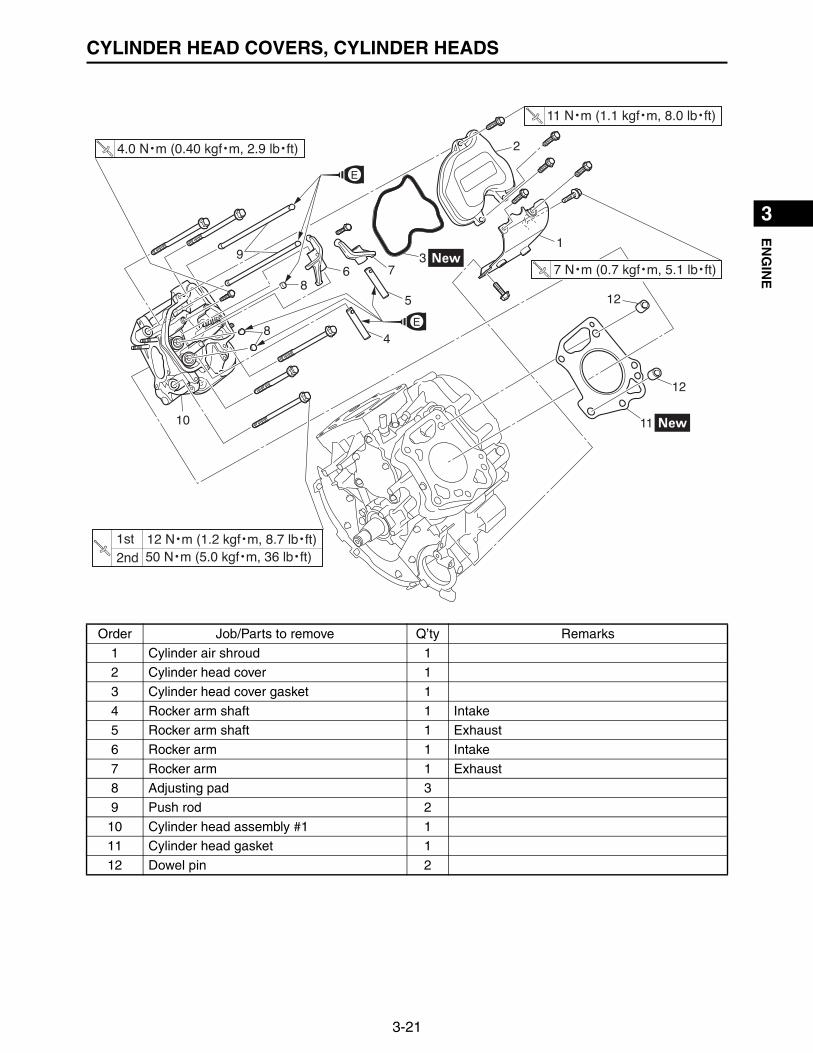
CYLINDER HEAD #1
Order Job/Parts to remove Q’ty Remarks
Removing the cylinder head covers, and cylinder heads
Remove the parts in the order listed.
Air filter case Refer to “AIR FILTER” on page 3-3.
ECU, rectifier/regulator and fuseRefer to “ECU, RECTIFIER/REGULATOR, AND FUSES” on page 3-8.
High and low-pressure fuel pump Refer to “FUEL PUMPS” on page 4-1.
Oil cooler Refer to “OIL COOLER” on page 3-5.
Fan case Refer to “CASE AND FAN” on page 3-11.
Flywheel and stator coil assemblyRefer to “FLYWHEEL AND STATOR COIL ASSEMBLY” on page 3-15.
Throttle body assemblyRefer to “THROTTLE BODY ASSEMBLY” on page 4-6.
Intake manifoldRefer to “FUEL INJECTORS AND INTAKE MANIFOLD” on page 4-9.
Starter motor assemblyRefer to “REMOVING THE STARTER MOTOR” on page 5-37.
11 N・m (1.1 kgf・m, 8.0 lb・ft)
4.0 N・m (0.40 kgf・m, 2.9 lb・ft)
7 N・m (0.7 kgf・m, 5.1 lb・ft)
50 N・m (5.0 kgf・m, 36 lb・ft) 12 N・m (1.2 kgf・m, 8.7 lb・ft) 1st
2nd
3-21
1
2
3
4
5
6
7
8
9
10
EN
GIN
ECYLINDER HEAD COVERS, CYLINDER HEADS
Order Job/Parts to remove Q’ty Remarks
1 Cylinder air shroud 1
2 Cylinder head cover 1
3 Cylinder head cover gasket 1
4 Rocker arm shaft 1 Intake
5 Rocker arm shaft 1 Exhaust
6 Rocker arm 1 Intake
7 Rocker arm 1 Exhaust
8 Adjusting pad 3
9 Push rod 2
10 Cylinder head assembly #1 1
11 Cylinder head gasket 1
12 Dowel pin 2
1
2
3
4
5
6 7
8
8
9
10 11
12
12
11 N・m (1.1 kgf・m, 8.0 lb・ft)
4.0 N・m (0.40 kgf・m, 2.9 lb・ft)
7 N・m (0.7 kgf・m, 5.1 lb・ft)
50 N・m (5.0 kgf・m, 36 lb・ft) 12 N・m (1.2 kgf・m, 8.7 lb・ft) 1st
2nd
3-22
1
2
3
4
5
6
7
8
9
10
EN
GIN
ECYLINDER HEAD COVERS, CYLINDER HEADS
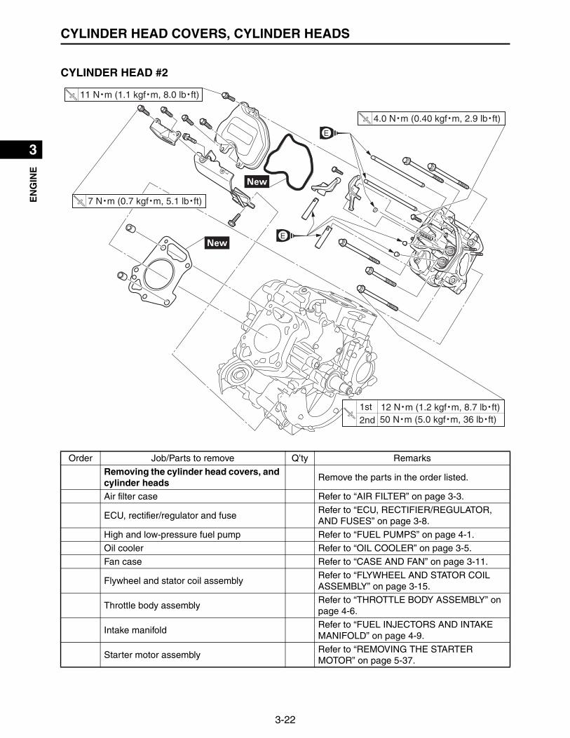
CYLINDER HEAD #2
Order Job/Parts to remove Q’ty Remarks
Removing the cylinder head covers, and cylinder heads
Remove the parts in the order listed.
Air filter case Refer to “AIR FILTER” on page 3-3.
ECU, rectifier/regulator and fuseRefer to “ECU, RECTIFIER/REGULATOR, AND FUSES” on page 3-8.
High and low-pressure fuel pump Refer to “FUEL PUMPS” on page 4-1.
Oil cooler Refer to “OIL COOLER” on page 3-5.
Fan case Refer to “CASE AND FAN” on page 3-11.
Flywheel and stator coil assemblyRefer to “FLYWHEEL AND STATOR COIL ASSEMBLY” on page 3-15.
Throttle body assemblyRefer to “THROTTLE BODY ASSEMBLY” on page 4-6.
Intake manifoldRefer to “FUEL INJECTORS AND INTAKE MANIFOLD” on page 4-9.
Starter motor assemblyRefer to “REMOVING THE STARTER MOTOR” on page 5-37.
11 N・m (1.1 kgf・m, 8.0 lb・ft)
7 N・m (0.7 kgf・m, 5.1 lb・ft)
4.0 N・m (0.40 kgf・m, 2.9 lb・ft)
50 N・m (5.0 kgf・m, 36 lb・ft) 12 N・m (1.2 kgf・m, 8.7 lb・ft) 1st
2nd

3-23
1
2
3
4
5
6
7
8
9
10
EN
GIN
ECYLINDER HEAD COVERS, CYLINDER HEADS
Order Job/Parts to remove Q’ty Remarks
1 Engine hunger 1 For maintenance.
2 Cylinder air shroud 1
3 Cylinder head cover 1
4 Cylinder head cover gasket 1
5 Rocker arm shaft 1 Intake
6 Rocker arm shaft 1 Exhaust
7 Rocker arm 1 Intake
8 Rocker arm 1 Exhaust
9 Adjusting pad 3
10 Push rod 2
11 Cylinder head assembly #2 1
12 Cylinder head gasket 1
13 Dowel pin 2
11 N・m (1.1 kgf・m, 8.0 lb・ft)
7 N・m (0.7 kgf・m, 5.1 lb・ft)
2
3
4
5
6
789
9
11
10
12
13
13
4.0 N・m (0.40 kgf・m, 2.9 lb・ft)
50 N・m (5.0 kgf・m, 36 lb・ft) 12 N・m (1.2 kgf・m, 8.7 lb・ft) 1st
2nd
1

3-24
1
2
3
4
5
6
7
8
9
10
EN
GIN
ECYLINDER HEAD COVERS, CYLINDER HEADS
CHECKING THE ROCKER ARMS AND ROCKER ARM SHAFTSThe following procedure applies to all of the rocker armsand rocker arm shafts.
1. Check:• Rocker arm “1”• Rocker arm shaft “2”
Wear/damage/cracks Replace.
CHECKING THE PUSH RODSThe following procedure applies to all of the push rods.
1. Check:• Push rod runout
Out of specifications Replace.
REMOVING THE CYLINDER HEADSThe following procedure applies to all of the cylinderheads.
1. Remove:• Cylinder head
TIP
Set the piston at TDC (top-dead-center) on the compres-sion stroke.(Refer to “ADJUSTING THE VALVE CLEARANCE” onpage 2-9.)
CHECKING THE CYLINDER HEADSThe following procedure applies to all of the cylinderheads.
1
2
Runout limit:0.3 mm (0.0118 in)

3-25
1
2
3
4
5
6
7
8
9
10
EN
GIN
ECYLINDER HEAD COVERS, CYLINDER HEADS
1. Check:• Cylinder head combustion chamber
Check the combustion chamber for carbon depos-its.Any carbon deposits Eliminate.
TIP
Be sure not to damage the sealing surface of the cylinderhead.
2. Check:• Cylinder head
Cracks/damage around the hole of spark plug Replace.
3. Measure:• Cylinder head warpage
TIP
Measure the warpage on the contact surface of the cylin-der head at six points using the straight edge and feelergauge set.
Out of specifications Resurface or replace.
INSTALLING THE CYLINDER HEAD ASSEMBLY
1. Install:• Cylinder head assembly #1• Cylinder head bolts “1” to “5”.
TIP
Tighten the bolts to the specified torque in two steps and inorder from “1” to “5”.
2. Install:• Cylinder head assembly #2• Cylinder head bolts “1” to “5”.
TIP
Tighten the bolts to the specified torque in two steps and inorder from “1” to “5”.
Warpage limit:0.05 mm (0.002 in)
1
2
3
4
55
Cylinder head bolt:1st: 12 N·m (1.2 kgf·m, 8.7 lb·ft)2nd: 50 N·m (5.0 kgf·m, 36 lb·ft)
TR..
1
2
3
4
5
5

3-26
1
2
3
4
5
6
7
8
9
10
EN
GIN
ECYLINDER HEAD COVERS, CYLINDER HEADS
Cylinder head bolt:1st: 12 N·m (1.2 kgf·m, 8.7 lb·ft)2nd: 50 N·m (5.0 kgf·m, 36 lb·ft)
TR..

3-27
1
2
3
4
5
6
7
8
9
10
EN
GIN
EVALVES
VALVES
Order Job/Parts to remove Q’ty Remarks
Removing the valvesRemove the parts in the order listed.The following procedure applies to both cylin-ders.
Cylinder head assemblyRefer to “CYLINDER HEAD COVERS, CYL-INDER HEADS” on page 3-20.
1 Valve cotter 3
2 Valve spring retainer 3
3 Intake valve spring 2
4 Exhaust valve spring 1
5 Intake valve 2
6 Exhaust valve 1
7 Valve stem seal 3
8 Valve spring seat 3
1
2
4
5
6
78
1
2
3
78
2
3
78
3-28
1
2
3
4
5
6
7
8
9
10
EN
GIN
EVALVES
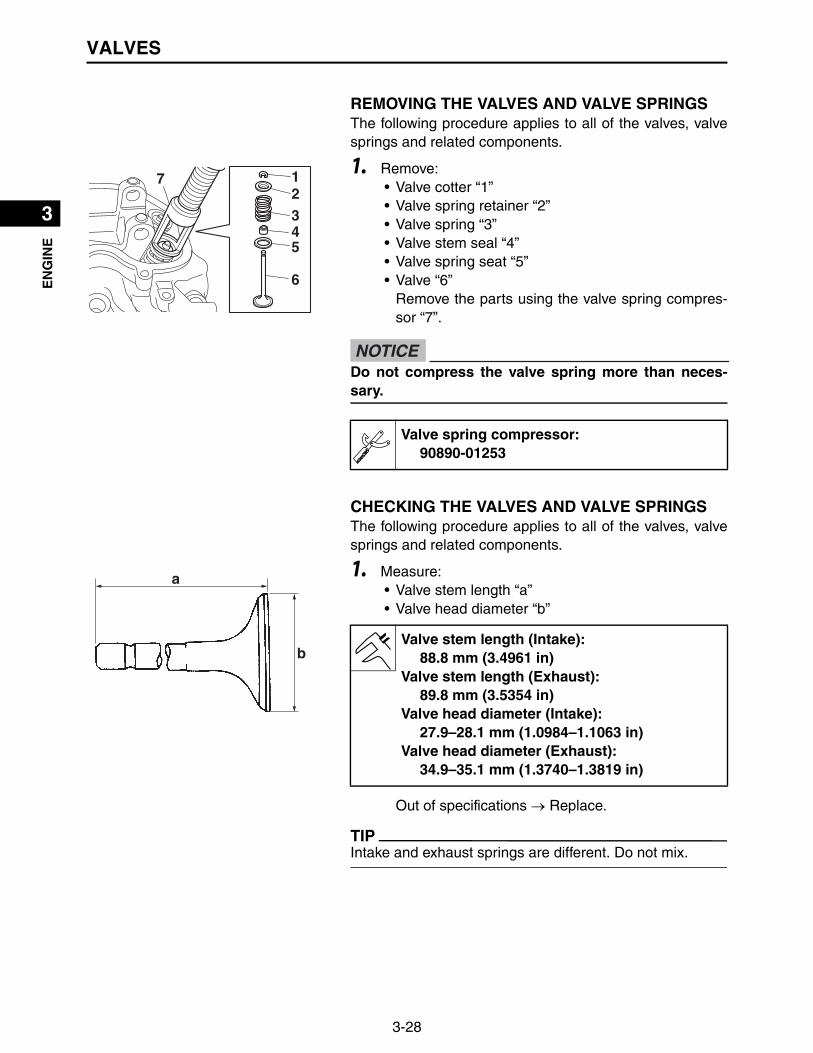
REMOVING THE VALVES AND VALVE SPRINGSThe following procedure applies to all of the valves, valvesprings and related components.
1. Remove:• Valve cotter “1”• Valve spring retainer “2”• Valve spring “3”• Valve stem seal “4”• Valve spring seat “5”• Valve “6”
Remove the parts using the valve spring compres-sor “7”.
CHECKING THE VALVES AND VALVE SPRINGSThe following procedure applies to all of the valves, valvesprings and related components.
1. Measure:• Valve stem length “a”• Valve head diameter “b”
Out of specifications Replace.
TIP
Intake and exhaust springs are different. Do not mix.
12345
6
7
Do not compress the valve spring more than neces-sary.
Valve spring compressor:90890-01253
NOTICE
b
a
Valve stem length (Intake):88.8 mm (3.4961 in)
Valve stem length (Exhaust):89.8 mm (3.5354 in)
Valve head diameter (Intake):27.9–28.1 mm (1.0984–1.1063 in)
Valve head diameter (Exhaust):34.9–35.1 mm (1.3740–1.3819 in)

3-29
1
2
3
4
5
6
7
8
9
10
EN
GIN
EVALVES
2. Measure:• Valve stem diameter “a”
Out of specifications Replace.
3. Measure:• Valve stem runout
Out of specifications Replace.
TIP
The value is half of that indicated on the dial indicatorgauge.
4. Measure:• Valve spring free length “a”
Out of specifications Replace.
5. Measure:• Compressed valve spring force “a”
Out of specification Replace.
aValve stem diameter (Intake):
5.948–5.963 mm (0.2342–0.2348 in)Valve stem diameter (Exhaust):
5.940–5.955 mm (0.2339–0.2344 in)Limit (Intake):
5.918 mm (0.2330 in)Limit (Exhaust):
5.910 mm (0.2327 in)
Valve stem runout limit:0.01 mm (0.0004 in)
a
Valve spring free length (Intake):37.1 mm (1.4606 in)
Valve spring free length (Exhaust):35.6 mm (1.4016 in)
Limit (Intake):35.25 mm (1.3878 in)
Limit (Exhaust):33.82 mm (1.3315 in)
b
a
b. Installed length

3-30
1
2
3
4
5
6
7
8
9
10
EN
GIN
EVALVES
6. Measure:• Valve spring tilt “a”
Out of specifications Replace.
7. Check:• Valve spring contact surface “a”
More than 2/3 of the contact surface does not con-tact Replace.
CHECKING THE VALVE SEATSThe following procedure applies to all of the valves andvalve seats.
1. Remove carbon deposits from the valve face andvalve seat.
2. Apply a small amount of coarse mechanic’s blue lay-out fluid to the valve face “a”.
3. Insert the valve into the valve guide and use a valvelapper to contact the valve face with the valve seat.
TIP
Do not rotate the valve while the valve face is contactingthe valve seat.
Installed compression spring force (Intake):67.7 N (6.90 kgf, 15.2 lbf)
Installed compression spring force (Exhaust):118.1 N (12.0 kgf, 26.5 lbf)
Installed length (Intake):29.3 mm (1.1535 in)
Installed length (Exhaust):29.0 mm (1.1417 in)
a
Tilt limit:2.0 mm (0.0787 in)
a
a

3-31
1
2
3
4
5
6
7
8
9
10
EN
GIN
EVALVES
4. Measure:• Valve face contact width “a”
Make sure that the contact width along the entirevalve face is within specifications.
Out of specification/rough/eccentric wear Replace.
5. Measure:• Valve seat contact width “a”
Make sure that the contact width along the entirevalve seat is within specifications.
Out of specification/rough/eccentric wear Replace.
VALVE LAPPING
1. Apply a coarse lapping compound evenly on the valveface. Lap the valve by tapping and rotating the valvelapper clockwise and counterclockwise.
2. Clean off all of the lapping compound from the valveface and valve seat. Apply fine lapping compound onthe valve face and lap the valve as described in step1.
aValve face contact width (Intake):
0.9–1.1 mm (0.0354–0.0433 in)Valve face contact width (Exhaust):
0.9–1.1 mm (0.0354–0.0433 in)Limit (Intake):
1.6 mm (0.063 in)Limit (Exhaust):
1.6 mm (0.063 in)
a Valve seat contact width (Intake):0.9–1.1 mm (0.0354–0.0433 in)
Valve seat contact width (Exhaust):0.9–1.1 mm (0.0354–0.0433 in)
Limit (Intake):1.6 mm (0.063 in)
Limit (Exhaust):1.6 mm (0.063 in)

3-32
1
2
3
4
5
6
7
8
9
10
EN
GIN
EVALVES
3. Once the contacting surface of the valve face is pol-ished and becomes shiny, apply mechanic’s blue lay-out fluid to make sure that there are traces of evencontact in the center of the valve face.
TIP
After every lapping procedure, clean off the compoundfrom the valve face and valve seat.
INSTALLING THE VALVES AND VALVE SPRINGSThe following procedure applies to all of the valves, valvesprings and related components.
1. Install:• Valve “1”• Valve spring seat “2”• Valve stem seal “3” • Valve spring “4”• Valve spring retainer “5”• Valve cotter “6”
Use the valve spring compressor “7” to install theparts.
Do not let the lapping compound enter the gapbetween the valve stem and the valve guide.
NOTICE
6 543
2
1
7
Valve spring compressor:90890-01253
New
New
a b
• Do not compress the spring more than necessary.• Surface “a” with the rounded edges of the valve cot-
ter must face downward (to the valve spring retainerside) when installing it on top of the valve springretainer. If surface “b” of the opposite side is facingdownward when the valve cotter is installed, it couldresult in the premature wear of the valve cotter.
NOTICE

3-33
1
2
3
4
5
6
7
8
9
10
EN
GIN
EOIL PUMP
OIL PUMP
Order Job/Parts to remove Q’ty Remarks
Removing the oil pump Remove the parts in the order listed.
Cylinder head assemblyRefer to “CYLINDER HEAD COVERS, CYL-INDER HEADS” on page 3-20.
1 Collar 1
2 Crankcase cover 2 1
3 Dowel pin 2
4 Relief valve 1
5 Oil pump cover 1
6 Oil strainer cover 1
7 Oil strainer 1
8 Inner rotor 1
9 Outer rotor 1
10 Oil seal 1
11 Oil pressure switch 1
10 N・m (1.0 kgf・m, 7.2 lb・ft)
27 N・m (2.7 kgf・m, 20 lb・ft)
27 N・m (2.7 kgf・m, 20 lb・ft)
30 N・m (3.0 kgf・m, 22 lb・ft)
30 N・m (3.0 kgf・m, 22 lb・ft) 12 N・m (1.2 kgf・m, 8.7 lb・ft) 1st
2nd
1
2
3
3
4
5
6
79
8
10
(11)
(3)
11
8 N・m (0.8 kgf・m, 5.8 lb・ft)

3-34
1
2
3
4
5
6
7
8
9
10
EN
GIN
EOIL PUMP
DISASSEMBLING THE OIL PUMP
1. Remove:• Crankcase cover 2
2. Remove:• Relief valve “1”
3. Remove:• Oil pump cover “1”
4. Remove:• Oil strainer cover “1”• Oil strainer “2”• Inner rotor “3”• Outer rotor “4”
CHECKING THE OIL PUMP
1. Check:• Inner rotor “1”• Outer rotor “2”
Cracks/damage/wear Replace the defectivepart(s).
2. Check:• Oil strainer “1”• Oil strainer cover “2”
Damage Replace.Contaminants Clean with solvent.
1
1
1
23
4
12
12
3-35
1
2
3
4
5
6
7
8
9
10
EN
GIN
EOIL PUMP
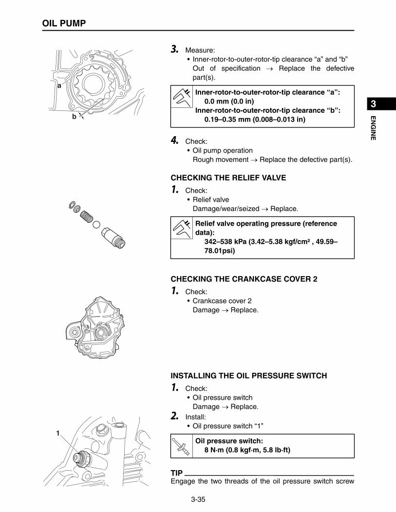
3. Measure:• Inner-rotor-to-outer-rotor-tip clearance “a” and “b”
Out of specification Replace the defectivepart(s).
4. Check:• Oil pump operation
Rough movement Replace the defective part(s).
CHECKING THE RELIEF VALVE
1. Check:• Relief valve
Damage/wear/seized Replace.
CHECKING THE CRANKCASE COVER 2
1. Check:• Crankcase cover 2
Damage Replace.
INSTALLING THE OIL PRESSURE SWITCH
1. Check:• Oil pressure switch
Damage Replace.
2. Install:• Oil pressure switch “1”
TIP
Engage the two threads of the oil pressure switch screw
a
b
Inner-rotor-to-outer-rotor-tip clearance “a”:0.0 mm (0.0 in)
Inner-rotor-to-outer-rotor-tip clearance “b”:0.19–0.35 mm (0.008–0.013 in)
Relief valve operating pressure (reference data):
342–538 kPa (3.42–5.38 kgf/cm² , 49.59–78.01psi)
1Oil pressure switch:
8 N·m (0.8 kgf·m, 5.8 lb·ft)TR..

3-36
1
2
3
4
5
6
7
8
9
10
EN
GIN
EOIL PUMP
with the crankcase cover 2, apply LOCTITE®, and tightento the specified torque.
ASSEMBLING THE OIL PUMP
1. Lubricate:• Inner rotor• Outer rotor
2. Install:• Outer rotor “1”• Inner rotor “2”• Oil strainer “3”• Oil strainer cover “4”
TIP
Face portion “a” of the oil strainer cover downward asshown in the illustration, and install it.
3. Install:• Oil pump cover “1”• Oil pump cover bolts
4. Install:• Relief valve “1”
Recommended lubricant:Engine oil
1
2 34
a
1
Oil pump cover bolt:10 N·m (1.0 kgf·m, 7.2 lb·ft)T
R..
1
Relief valve:30 N·m (3.0 kgf·m, 22 lb·ft)T
R..

3-37
1
2
3
4
5
6
7
8
9
10
EN
GIN
EOIL PUMP
INSTALLING THE CRANKCASE COVER 2
1. Clean:• Mating surfaces of the crankcase and the crank-
case cover 2(with a cloth dampened with lacquer thinner)
2. Apply:• Sealant
(onto the crankcase cover 2 mating surfaces)
3. Install:• Crankcase cover 2
TIP
Align the inner rotor “a” of the oil pump with the flat portion“b” of the crankshaft and install.
4. Install:• Crankcase cover 2 bolts “1” to “11”
TIP
Tighten the bolts to the specified torque in two steps and inorder from “1” to “11”.
Three bond No.1217G®
ab
11
1
2
3
4
5
6
7
8
9
10
11
Crankcase cover 2 bolt:1st: 12 N·m (1.2 kgf·m, 8.7 lb·ft)2nd: 30 N·m (3.0 kgf·m, 22 lb·ft)
TR..
3-38
1
2
3
4
5
6
7
8
9
10
EN
GIN
EPISTONS, CAMSHAFT, CRANKCASE, AND CRANKSHAFT
PISTONS, CAMSHAFT, CRANKCASE, AND CRANKSHAFT
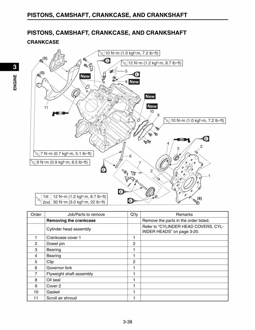
CRANKCASE
Order Job/Parts to remove Q’ty Remarks
Removing the crankcase Remove the parts in the order listed.
Cylinder head assemblyRefer to “CYLINDER HEAD COVERS, CYL-INDER HEADS” on page 3-20.
1 Crankcase cover 1 1
2 Dowel pin 2
3 Bearing 1
4 Bearing 1
5 Clip 2
6 Governor fork 1
7 Flyweight shaft assembly 1
8 Oil seal 1
9 Cover 2 1
10 Gasket 1
11 Scroll air shroud 1
1
2
2
34
5
6
7
8
910
11
(8)
(5)
(5)
9 N・m (0.9 kgf・m, 6.5 lb・ft)
10 N・m (1.0 kgf・m, 7.2 lb・ft)
10 N・m (1.0 kgf・m, 7.2 lb・ft)
12 N・m (1.2 kgf・m, 8.7 lb・ft)
7 N・m (0.7 kgf・m, 5.1 lb・ft)
30 N・m (3.0 kgf・m, 22 lb・ft) 12 N・m (1.2 kgf・m, 8.7 lb・ft) 1st
2nd

3-39
1
2
3
4
5
6
7
8
9
10
EN
GIN
EPISTONS, CAMSHAFT, CRANKCASE, AND CRANKSHAFT
Order Job/Parts to remove Q’ty Remarks
12 Cover 1 1
13 Dowel pin 2
14 Reed valve 1
15 Engine temperature sensor 1
16 Oil seal 1
1213 14
15
16
(8)
(5)
(5)
9 N・m (0.9 kgf・m, 6.5 lb・ft)
10 N・m (1.0 kgf・m, 7.2 lb・ft)
10 N・m (1.0 kgf・m, 7.2 lb・ft)
12 N・m (1.2 kgf・m, 8.7 lb・ft)
7 N・m (0.7 kgf・m, 5.1 lb・ft)
30 N・m (3.0 kgf・m, 22 lb・ft) 12 N・m (1.2 kgf・m, 8.7 lb・ft) 1st
2nd

3-40
1
2
3
4
5
6
7
8
9
10
EN
GIN
EPISTONS, CAMSHAFT, CRANKCASE, AND CRANKSHAFT
PISTONS, CAMSHAFT, AND CRANKSHAFT
Order Job/Parts to remove Q’ty Remarks
Removing the pistons, camshaft, and crankshaft
Remove the parts in the order listed.
1 Camshaft 1
2 Valve lifter 4
3 Connecting rod cap 2
4 Crankshaft 1
5 Connecting rod 2
6 Piston pin circlip 4
7 Piston pin 2
8 Piston 2
9 Top ring 2
10 2nd ring 2
11 Oil ring 2
1
2
22
3
4
5
6
67
8
910
11
3
5
6
678
9
10
11
20 N・m (2.0 kgf・m, 14 lb・ft)
20 N・m (2.0 kgf・m, 14 lb・ft)

3-41
1
2
3
4
5
6
7
8
9
10
EN
GIN
EPISTONS, CAMSHAFT, CRANKCASE, AND CRANKSHAFT
REMOVING THE FLYWEIGHT SHAFT ASSEMBLY AND GOVERNOR FORK
1. Remove:• Crankcase cover 1• Governor assembly
2. Remove:• Clips “1”• Governor fork “2”• Washers “3”
3. Remove:• Flyweight shaft assembly “1”• Washer “2”
TIP
Remove the flyweight shaft assembly by tapping theweight shaft from outside of the crankcase cover 1.
DISASSEMBLING THE FLYWEIGHT SHAFT ASSEMBLY
1. Remove:• Flyweight shafts “1”• Weights “2”• Collar “3”• Washer “4”• Circlip “5”• Weight shaft “6”
CHECKING THE FLYWEIGHT SHAFT ASSEMBLY
1. Check:• Flyweight shaft assembly move smoothly
Rough movement Replace.
1
2
33
2
1
1
23
45
61
1

3-42
1
2
3
4
5
6
7
8
9
10
EN
GIN
EPISTONS, CAMSHAFT, CRANKCASE, AND CRANKSHAFT
2. Check:• Weight• Flyweight shaft• Collar• Washer• Weight shaft
Wear/damage Replace.
ASSEMBLING THE FLYWEIGHT SHAFT ASSEMBLY
1. Install:• Weight shaft “1”• Circlip “2” • Washer “3”• Collar “4”• Weights “5”• Flyweight shafts “6”
INSTALLING THE FLYWEIGHT SHAFT ASSEMBLY AND GOVERNOR FORK
1. Install:• Washer “1”• Flyweight shaft assembly “2”
2. Install:• Washers “1”• Governor fork “2”• Clips “3”
3. Install:• Governor assembly• Crankcase cover 1
(Refer to “INSTALLING THE CRANKCASE COVER1” on page 3-47)
4. Adjust:• Governor
6
6
6
54
32
1
New
2
1
1 1
2
3

3-43
1
2
3
4
5
6
7
8
9
10
EN
GIN
EPISTONS, CAMSHAFT, CRANKCASE, AND CRANKSHAFT
(Refer to “INSTALLING THE THROTTLE BODYASSEMBLY” on page 4-7)
REMOVING THE CAMSHAFT AND VALVE LIFTERSThe following procedure applies to all of the camshaft andvalve lifters.
1. Remove:• Camshaft “1”
TIP
Remove the camshaft when the camshaft gear mark “a”and the crankshaft gear mark “b” are aligned.
2. Remove:• Valve lifter “1” (Intake)• Valve lifter “2” (Exhaust)
CHECKING THE CAMSHAFT
1. Check:• Camshaft
Crack/damage/wear Replace.
a
b
1
1 1
2 2
Mark the valve lifters so as not to confuse them duringreassembly.
NOTICE

3-44
1
2
3
4
5
6
7
8
9
10
EN
GIN
EPISTONS, CAMSHAFT, CRANKCASE, AND CRANKSHAFT
2. Check:• Camshaft lobe dimensions “a” and “b”
Out of specification Replace.
3. Check:• Surface of camshaft gear teeth
Crack/damage/wear Replace.
4. Check:• Camshaft journal diameter “a”
Out of specification Replace.
CHECKING THE VALVE LIFTERSThe following procedure applies to all of the valve lifters.
a
b
Camshaft lobe dimensionsLobe height “a” (Intake):
32.885 mm (1.2947 in)Limit:
32.785 mm (1.2907 in)Lobe height “a” (Exhaust):
33.957 mm (1.3369 in)Limit:
33.857 mm (1.3330 in)Base circle diameter “b” (Intake):
26.000 mm (1.0236 in)Limit:
25.900 mm (1.0197 in)Base circle diameter “b” (Exhaust):
26.000 mm (1.0236 in)Limit:
25.900 mm (1.0197 in)
a
a
Camshaft journal diameter:16.965–16.990 mm (0.6679–0.6689 in)
Limit:16.950 mm (0.6673 in)

3-45
1
2
3
4
5
6
7
8
9
10
EN
GIN
EPISTONS, CAMSHAFT, CRANKCASE, AND CRANKSHAFT
1. Check:• Valve lifter
Damage Replace.
CHECKING THE REED VALVE
1. Check:• Reed valve
Damage Replace.
INSTALLING THE VALVE LIFTERS AND CAMSHAFTThe following procedure applies to all of the camshaft andvalve lifters.
1. Install:• Valve lifter “1” (Intake)• Valve lifter “2” (Exhaust)
2. Install:• Camshaft “1”
INSTALLING THE COVER 1
1. Clean:• Mating surfaces of the crankcase and the cover 1
(with a cloth dampened with lacquer thinner)
1 1
2 2
a
b
1Be sure to align the camshaft gear mark “a” with thecrankshaft gear mark “b”.
NOTICE

3-46
1
2
3
4
5
6
7
8
9
10
EN
GIN
EPISTONS, CAMSHAFT, CRANKCASE, AND CRANKSHAFT
2. Apply:• Sealant
(onto the crankcase mating surfaces)
3. Install:• Cover 1• Cover 1 bolts “1” to “5”
TIP
Tighten the bolts to the specified torque in order from “1” to“5”.
INSTALLING THE COVER 2
1. Install:• Gasket • Cover 2• Cover 2 bolts “1” to “5”
TIP
Tighten the bolts to the specified torque in order from “1” to“5”.
CHECKING THE CRANKCASE COVER 1
1. Check:• Crankcase cover 1
Damage Replace.• Bearing
Noise/wear/rotational failure Replace.
Three bond No.1217G®
51
23
4
5
Cover 1 bolt:9 N·m (0.9 kgf·m, 6.5 lb·ft)T
R..
5
1
2
3
4 5
Cover 2 bolt:10 N·m (1.0 kgf·m, 7.2 lb·ft)
New
TR..

3-47
1
2
3
4
5
6
7
8
9
10
EN
GIN
EPISTONS, CAMSHAFT, CRANKCASE, AND CRANKSHAFT
INSTALLING THE CRANKCASE COVER 1
1. Install:• Crankcase cover 1• Crankcase cover 1 bolts “1” to “8”
TIP
Tighten the bolts to the specified torque in two steps and inorder from “1” to “8”.
CHECKING THE CYLINDERS AND PISTONSThe following procedure applies to all of the pistons andcylinders.
1. Check:• Piston wall• Cylinder wall
Vertical scratches Replace the cylinder, andreplace the piston and piston rings as a set.
2. Measure:• Cylinder warpage
TIP
Measure the warpage on the contact surface of the cylin-der head at six points using a straight edge and feelergauge set.
Out of specification Replace the crankcaseassembly.
3. Measure:• Piston-to-cylinder clearance
▼▼▼▼▼▼▼▼▼▼▼▼▼▼▼▼▼▼▼▼▼▼▼▼▼▼▼▼▼▼▼▼▼▼▼▼▼▼▼▼▼
a. Measure cylinder bore “C” with the cylinder boregauge.
1 2
3
4
5
6 7
8
8
Crankcase cover 1 bolt:1st: 12 N·m (1.2 kgf·m, 8.7 lb·ft)2nd: 30 N·m (3.0 kgf·m, 22 lb·ft)
TR..
Feeler gauge set:YU-26900-9
Warpage limit:0.05 mm (0.002 in)

3-48
1
2
3
4
5
6
7
8
9
10
EN
GIN
EPISTONS, CAMSHAFT, CRANKCASE, AND CRANKSHAFT
TIP
Measure cylinder bore “C” by taking side-to-side and front-to-back measurements of the cylinder.
b. If out of specification, replace the crankcaseassembly, and replace the piston and piston ringsas a set.
c. Measure piston skirt diameter “P” with the microm-eter.a = 6.0 mm (0.2362 in) from the piston bottom edge
d. If out of specification, replace the piston and pistonrings as a set.
e. Calculate the piston-to-cylinder clearance with thefollowing formula.
f. If out of specification, replace the crankcaseassembly, and replace the piston and piston ringsas a set.
▲▲▲▲▲▲▲▲▲▲▲▲▲▲▲▲▲▲▲▲▲▲▲▲▲▲▲▲▲▲▲▲▲▲▲▲▲▲▲▲▲
Bore:80.000–80.020 mm (3.1496–3.1504 in)
Warpage limit:80.025 mm (3.1506 in)
“C” = maximum of D1, D2, D3, D4, D5, D6
Pa
Piston diameter:79.959–79.980 mm (3.1480–3.1488 in)
Limit:79.900 mm (3.1457 in)
Piston-to-cylinder clearance = Cylinder bore “C” – Piston skirt diameter “P”
Piston-to-cylinder clearance:0.033–0.047 mm (0.0013–0.0019 in)
Limit:0.15 mm (0.0059 in)
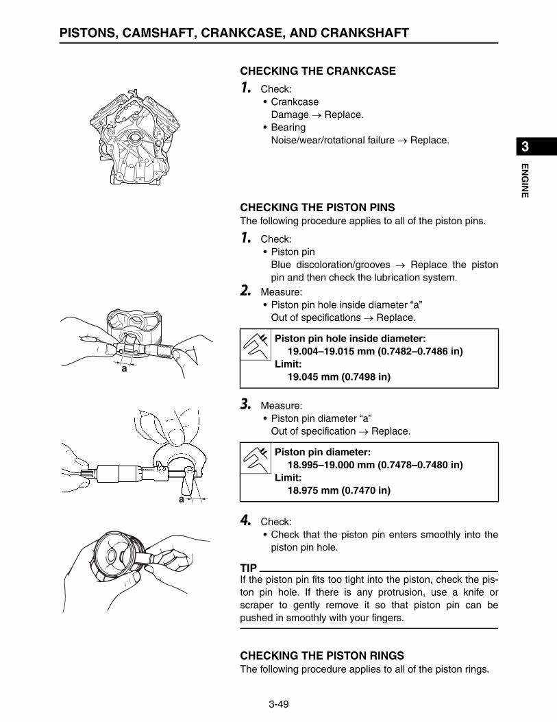
3-49
1
2
3
4
5
6
7
8
9
10
EN
GIN
EPISTONS, CAMSHAFT, CRANKCASE, AND CRANKSHAFT
CHECKING THE CRANKCASE
1. Check:• Crankcase
Damage Replace.• Bearing
Noise/wear/rotational failure Replace.
CHECKING THE PISTON PINSThe following procedure applies to all of the piston pins.
1. Check:• Piston pin
Blue discoloration/grooves Replace the pistonpin and then check the lubrication system.
2. Measure:• Piston pin hole inside diameter “a”
Out of specifications Replace.
3. Measure:• Piston pin diameter “a”
Out of specification Replace.
4. Check:• Check that the piston pin enters smoothly into the
piston pin hole.
TIP
If the piston pin fits too tight into the piston, check the pis-ton pin hole. If there is any protrusion, use a knife orscraper to gently remove it so that piston pin can bepushed in smoothly with your fingers.
CHECKING THE PISTON RINGSThe following procedure applies to all of the piston rings.
a
Piston pin hole inside diameter:19.004–19.015 mm (0.7482–0.7486 in)
Limit:19.045 mm (0.7498 in)
a
Piston pin diameter:18.995–19.000 mm (0.7478–0.7480 in)
Limit:18.975 mm (0.7470 in)

3-50
1
2
3
4
5
6
7
8
9
10
EN
GIN
EPISTONS, CAMSHAFT, CRANKCASE, AND CRANKSHAFT
1. Measure:• Piston ring side clearance
Out of specification Replace the piston and pis-ton rings as a set.
TIP
Before measuring the piston ring side clearance, eliminateany carbon deposits from the piston ring grooves and pis-ton rings.
2. Install:• Piston ring
(into the cylinder)
TIP
Use the piston crown to level the piston ring near bottom ofcylinder “a”, where cylinder wear is lowest.
3. Measure:• Piston ring end gap
Out of specification Replace the piston rings as aset.
Piston ringTop ring
Side clearance:0.04–0.08 mm (0.0016–0.0031 in)
Limit:0.13 mm (0.0051 in)
2nd ringSide clearance:
0.03–0.07 mm (0.0012–0.0028 in)Limit:
0.13 mm (0.0051 in)
a
bb. Upper of cylinder

3-51
1
2
3
4
5
6
7
8
9
10
EN
GIN
EPISTONS, CAMSHAFT, CRANKCASE, AND CRANKSHAFT
CHECKING THE CRANKSHAFT
1. Check:• Crankshaft sprocket “1”
Damage/wear Replace the crankshaft.
2. Measure:• Crankshaft runout limit
Out of specification Replace.Use a dial indicator gauge.
3. Measure:• Crank pin outside diameter “a”
Out of specification Replace.Use a micrometer.
Top ringEnd gap (installed):
0.20–0.35 mm (0.0079–0.0138 in)Limit:
0.60 mm (0.0236 in)2nd ring
End gap (installed):0.20–0.35 mm (0.0079–0.0138 in)
Limit:0.60 mm (0.0236 in)
Oil ringEnd gap (installed):
0.20–0.70 mm (0.0079–0.0276 in)
1
Dial indicator gauge:YU-A8428
Runout limit:0.03 mm (0.0012 in)
a
Crank pin outside diameter:40.950–41.050 mm (1.6122–1.6161 in)

3-52
1
2
3
4
5
6
7
8
9
10
EN
GIN
EPISTONS, CAMSHAFT, CRANKCASE, AND CRANKSHAFT
CHECKING THE CONNECTING RODS OIL CLEARANCEThe following procedure applies to all of the connectingrods.
TIP
Measure the oil clearance if replacing the crankshaft orconnecting rod.
1. Place a piece of Plastigauge® “1” on the crank pinhorizontally.
TIP
Wipe off oil thoroughly from the crankshaft, connectingrod, and connecting rod cap.
2. Install:• Connecting rod “1”• Connecting rod cap “2”
TIP
Tighten the cap bolts so that the crankshaft does not movewhile the oil clearance is being measured.
3. Remove:• Connecting rod cap• Connecting rod
4. Measure:• Connecting rod big end oil clearance
Out of specification Replace crankshaft or con-necting rod assembly, and then measure the clear-ance again.
TIP
Measure the widest portion of the pressed Plastigauge®.
INSTALLING THE PISTONS AND PISTON RINGSThe following procedure applies to all of the pistons, piston
1
1
2
Connecting rod cap bolt:20 N·m (2.0 kgf·m, 14 lb·ft)T
R..
Connecting rod big end oil clearance:0.016–0.046 mm (0.0006–0.0018 in)
Limit:0.09 mm (0.0035 in)

3-53
1
2
3
4
5
6
7
8
9
10
EN
GIN
EPISTONS, CAMSHAFT, CRANKCASE, AND CRANKSHAFT
rings and related components.
1. Install:• Top ring “1”• 2nd ring “2”• Oil ring “3”
TIP
• Be sure to install the top ring so that the “R” mark “a”faces toward the piston head.
• Be sure to install the 2nd ring so that the “RN” mark “b”faces toward the piston head.
• Make sure that the piston rings move smoothly.
2. Apply the engine oil to the inside of the connecting rodsmall end.
3. Install:• Piston “1”• Piston pin “2”• Piston pin circlips “3”
TIP
• Make sure that the “ ” mark “a” on the piston headfaces toward the flywheel.
• Install the piston pin clips so that the clip ends are 45“b” or more from the cutout in the piston.
12
3
2
1
ab
1 23
a
#1 #2
1 3
2
b
New
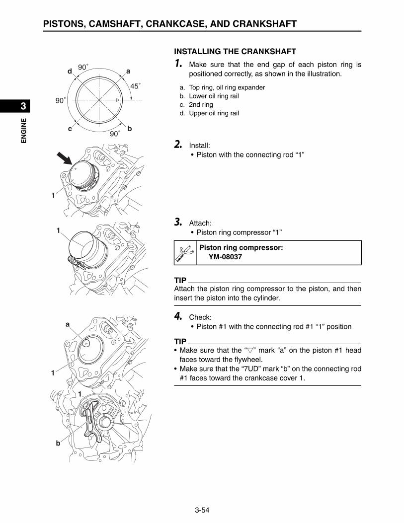
3-54
1
2
3
4
5
6
7
8
9
10
EN
GIN
EPISTONS, CAMSHAFT, CRANKCASE, AND CRANKSHAFT
INSTALLING THE CRANKSHAFT
1. Make sure that the end gap of each piston ring ispositioned correctly, as shown in the illustration.
2. Install:• Piston with the connecting rod “1”
3. Attach:• Piston ring compressor “1”
TIP
Attach the piston ring compressor to the piston, and theninsert the piston into the cylinder.
4. Check:• Piston #1 with the connecting rod #1 “1” position
TIP
• Make sure that the “ ” mark “a” on the piston #1 headfaces toward the flywheel.
• Make sure that the “7UD” mark “b” on the connecting rod#1 faces toward the crankcase cover 1.
45˚
90˚
90˚
90˚
a
bc
d
a. Top ring, oil ring expanderb. Lower oil ring railc. 2nd ringd. Upper oil ring rail
1
1
Piston ring compressor:YM-08037
a
1
1
b

3-55
1
2
3
4
5
6
7
8
9
10
EN
GIN
EPISTONS, CAMSHAFT, CRANKCASE, AND CRANKSHAFT
5. Check:• Piston #2 with the connecting rod #2 “1” position.
TIP
• Make sure that the “ ” mark “a” on the piston #2 headfaces toward the flywheel.
• Make sure that the “YAMAHA” mark “b” on the connect-ing rod #2 faces toward the crankcase cover 1.
6. Install:• Crankshaft “1”
7. Install:• Connecting rod cap #1 “1”• Connecting rod cap #1 bolts “2”
TIP
• Make sure that the “ ” mark “a” on the connecting rod #1
is aligned with the “ ” mark “b” on the connecting rod cap#1.
• Tighten the connecting rod cap #1 bolts alternately twoto three times.
a
1
1
b
1
21
2 21
a
b
Connecting rod cap bolt:20 N·m (2.0 kgf·m, 14 lb·ft)T
R..
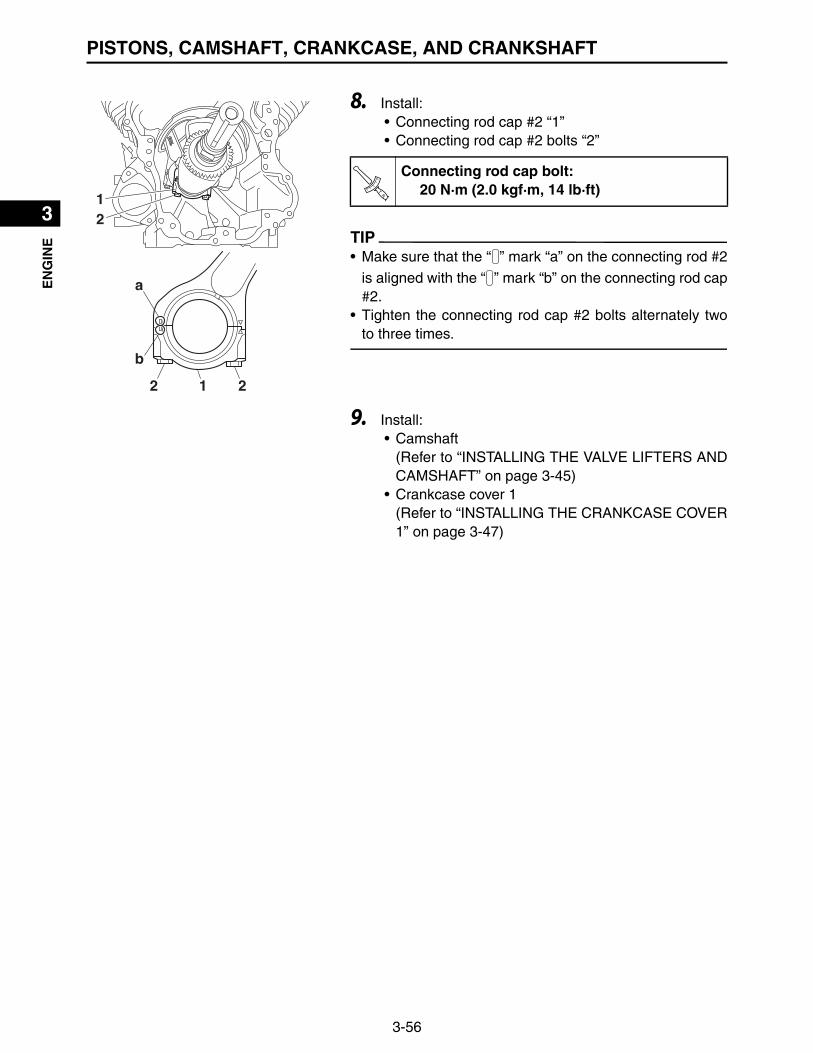
3-56
1
2
3
4
5
6
7
8
9
10
EN
GIN
EPISTONS, CAMSHAFT, CRANKCASE, AND CRANKSHAFT
8. Install:• Connecting rod cap #2 “1”• Connecting rod cap #2 bolts “2”
TIP
• Make sure that the “ ” mark “a” on the connecting rod #2
is aligned with the “ ” mark “b” on the connecting rod cap#2.
• Tighten the connecting rod cap #2 bolts alternately twoto three times.
9. Install:• Camshaft
(Refer to “INSTALLING THE VALVE LIFTERS ANDCAMSHAFT” on page 3-45)
• Crankcase cover 1(Refer to “INSTALLING THE CRANKCASE COVER1” on page 3-47)
21
2 21
a
b
Connecting rod cap bolt:20 N·m (2.0 kgf·m, 14 lb·ft)T
R..

1
2
3
4
5
6
7
8
9
10
FU
EL
4-1
FUELFUEL PUMPS
Order Job/Parts to remove Q’ty Remarks
Removing the fuel pumps Remove the parts in the order listed.
1 Fuel filter 1
2 Fuel hose 1
3 Low-pressure fuel pump 1
4 Fuel pump bracket 1
5 Fuel injector pipe 1 1 Disconnect.
6 Purge hose 2 1 Disconnect.
7 High-pressure fuel pump lead coupler 1 Disconnect.
8 High-pressure fuel pump 1
9 Fuel pump bracket 1
10 Pulsar hose 1
11 Fuel delivery hose 1
7 N・m (0.7 kgf・m, 5.1 lb・ft)
9 N・m (0.9 kgf・m, 6.5 lb・ft) 9 N・m (0.9 kgf・m, 6.5 lb・ft)
1
2
3
5
6
7
8
9
11 10
4

4-2
1
2
3
4
5
6
7
8
9
10
FU
EL
FUEL PUMPS
REMOVING THE HIGH-PRESSURE FUEL PUMP
1. Disconnect:• Fuel injector pipe 1 “1”
TIP
• To remove the fuel injector pipe 1 from the high-pressurefuel pump joint, press the two buttons “2” on the sides ofthe connector, and then remove the pipe.
• Before removing the pipe, place a few rags in the areaunder where it will be removed.
2. Disconnect:• High-pressure fuel pump lead coupler
TIP
Slide the coupler cover “a” upward as shown in the illustra-tion, and remove the coupler.
3. Remove:• High-pressure fuel pump
Cover fuel injector pipe 1 connections with a clothwhen disconnecting them. Residual pressure in thefuel lines could cause fuel to spurt out when removingthe fuel injector pipe 1.
WARNING
1
Be sure to disconnect the fuel injector pipe 1 “1” byhand. Do not forcefully disconnect the hose with tools.
NOTICE
2
a a

4-3
1
2
3
4
5
6
7
8
9
10
FU
EL
FUEL PUMPS
CHECKING THE LOW-PRESSURE FUEL PUMP
1. Check:• Fuel hose “1”• Fuel delivery hose “2”• Pulsar hose “3”• Low-pressure fuel pump “4”
Cracks/damage Replace.
2. Check:• Low-pressure fuel pump operation
▼▼▼▼▼▼▼▼▼▼▼▼▼▼▼▼▼▼▼▼▼▼▼▼▼▼▼▼▼▼▼▼▼▼▼▼▼▼▼▼▼
a. Connect the manual vacuum pump (Pressure/vac-uum tester) “1” to the pulsar hose “2”.
b. Place the container underneath the end of the fueldelivery hose “3”.
c. Operate the manual vacuum pump (Pressure/vac-uum tester) “1” and check that gasoline is flowingout of the fuel delivery hose “3”.
d. If not, replace the fuel pump assembly.▲▲▲▲▲▲▲▲▲▲▲▲▲▲▲▲▲▲▲▲▲▲▲▲▲▲▲▲▲▲▲▲▲▲▲▲▲▲▲▲▲
CHECKING THE HIGH-PRESSURE FUEL PUMP
1. Check:• High-pressure fuel pump
Cracks/damage Replace.
2. Check:• Fuel pressure
▼▼▼▼▼▼▼▼▼▼▼▼▼▼▼▼▼▼▼▼▼▼▼▼▼▼▼▼▼▼▼▼▼▼▼▼▼▼▼▼▼
a. Disconnect the fuel injector pipe 1 “1” from the fuelpump.Refer to “REMOVING THE HIGH-PRESSUREFUEL PUMP” on page 4-2.
1
23
4
213
Pressure/vacuum tester:YB-35956-B
1Cover fuel injector pipe 1 connections with a clothwhen disconnecting them. Residual pressure in thefuel lines could cause fuel to spurt out when removingthe fuel injector pipe 1.
WARNING

4-4
1
2
3
4
5
6
7
8
9
10
FU
EL
FUEL PUMPS
b. Connect the Fuel pressure gauge “2” and fuel pres-sure adapter “3” to the fuel injector pipe 1.
c. Start the engine.d. Measure the fuel pressure.
Faulty Replace the fuel pump.
▲▲▲▲▲▲▲▲▲▲▲▲▲▲▲▲▲▲▲▲▲▲▲▲▲▲▲▲▲▲▲▲▲▲▲▲▲▲▲▲▲
INSTALLING THE HIGH-PRESSURE FUEL PUMP
1. Install:• High-pressure fuel pump
2. Connect:• High-pressure fuel pump lead coupler
TIP
Insert the coupler securely, slide the coupler cover “a”downward as shown in the illustration, and then lock thecoupler.
3. Connect:• Fuel injector pipe 1
TIP
Install the fuel injector pipe 1 securely onto the high-pres-
Be sure to disconnect the fuel injector pipe 1 by hand.Do not forcefully disconnect the hose with tools.
NOTICE
3
2
Fuel pressure gauge:YU-03153
Fuel pressure adapter:YM-03186
Fuel line pressure (at idle):255–285 kPa (2.55–2.85 kgf/cm², 36.98–41.33 psi)
aa
When connecting the fuel injector pipe 1, make surethat it is securely connected, and that the fuel injectorpipe 1 connector on the fuel injector pipe 1 is in thecorrect position, otherwise the fuel injector pipe 1 willnot be properly installed.
NOTICE
4-5
1
2
3
4
5
6
7
8
9
10
FU
EL
FUEL PUMPS
sure fuel pump joint until a distinct “click” is heard.

4-6
1
2
3
4
5
6
7
8
9
10
FU
EL
THROTTLE BODY ASSEMBLY
THROTTLE BODY ASSEMBLY
Order Job/Parts to remove Q’ty Remarks
Removing the throttle body assembly Remove the parts in the order listed.
Air filter case Refer to “AIR FILTER” on page 3-3.
1 Governor spring 1
2 Governor assembly 1
3 Throttle lever comp 1
4 Link rod/spring 1/1
5 Stay 1
6 Breather hose 1
7 Joint 1 1
8 Gasket 1
9 Throttle body assembly lead coupler 1 Disconnect.
10 Throttle body assembly 1
11 Gasket 1
12
3
4
5
6
7
8
910
11
8 N・m (0.8 kgf・m, 5.8 lb・ft)
7 N・m (0.7 kgf・m, 5.1 lb・ft)
1.1 N・m (0.11 kgf・m, 0.80 lb・ft)

4-7
1
2
3
4
5
6
7
8
9
10
FU
EL
THROTTLE BODY ASSEMBLY
REMOVING THE THROTTLE BODY ASSEMBLY
1. Remove:• Governor spring• Governor assembly• Throttle lever comp• Link rod/spring
2. Remove:• Stay “1”• Breather hose “2”• Joint 1 “3”• Throttle body assembly “4”• Gaskets “5”
CHECKING THE THROTTLE BODY ASSEMBLY
1. Check:• Throttle body assembly
Cracks/damage Replace.
2. Check:• Throttle valve operation
Throttle valve can not move smoothly Replace.• Engine speed adjustment
Can not adjust engine high/low engine speed byprocedure on page 2-16 Replace.
INSTALLING THE THROTTLE BODY ASSEMBLY
1. Install:• Gaskets “1” • Throttle body assembly “2”• Joint 1 “3”• Breather hose “4”• Stay “5”• Throttle body assembly nuts
1
5
5
2
3
4
5
1
1
4
3
2
Throttle body assembly nut:7 N·m (0.7 kgf·m, 5.1 lb·ft)
New
TR..

4-8
1
2
3
4
5
6
7
8
9
10
FU
EL
THROTTLE BODY ASSEMBLY
2. Install:• Link rod/spring• Throttle lever comp• Governor assembly• Governor spring “1”
TIP
• Install the bending portion (short) “a” of the governorspring “1” into the hole “c” of the throttle lever comp whileinstalling the bending portion (long) “b” of the governorspring “1” into the hole “d” of the governor assembly.
• Install the governor spring to the throttle lever comp first,and then to the governor assembly.
3. Adjust:• Governor • Governor assembly
▼▼▼▼▼▼▼▼▼▼▼▼▼▼▼▼▼▼▼▼▼▼▼▼▼▼▼▼▼▼▼▼▼▼▼▼▼▼▼▼▼
a. Loosen the governor assembly bolt “1”.b. Turn the governor assembly “2” counterclockwise
until it stops.c. Turn the governor fork “3” counterclockwise until it
stops.d. Tighten the governor assembly bolt “1”.
▲▲▲▲▲▲▲▲▲▲▲▲▲▲▲▲▲▲▲▲▲▲▲▲▲▲▲▲▲▲▲▲▲▲▲▲▲▲▲▲▲
4. Check:• Engine speed
(Refer to “ENGINE SPEED” on page 2-14)
1
a
b
c
d
1
23
Governor assembly bolt:8 N·m (0.8 kgf·m, 5.8 lb·ft)
High engine speed (with no load):3550–3600 r/min
Low engine speed (with no load):1450–1550 r/min
TR..

4-9
1
2
3
4
5
6
7
8
9
10
FU
EL
FUEL INJECTORS AND INTAKE MANIFOLD
FUEL INJECTORS AND INTAKE MANIFOLD
Order Job/Parts to remove Q’ty Remarks
Removing the fuel injectors and intake manifold
Remove the parts in the order listed.
Air filter case Refer to “AIR FILTER” on page 3-3.
ECU and rectifier/regulatorRefer to “ECU, RECTIFIER/REGULATOR, AND FUSES” on page 3-8.
Low-pressure fuel pump Refer to “FUEL PUMPS” on page 4-1.
Oil cooler Refer to “OIL COOLER” on page 3-5.
Fan case and fan Refer to “CASE AND FAN” on page 3-11.
Throttle body assembly Refer to “THROTTLE BODY ASSEMBLY” on page 4-6.
Ignition coil Refer to “IGNITION COILS” on page 3-10.
1 Purge hose 1
2 Fuel injector #1 lead coupler 1 Disconnect.
3 Fuel injector #2 lead coupler 1 Disconnect.
1
23
7 N・m (0.7 kgf・m, 5.1 lb・ft) 3.0 N・m (0.30 kgf・m, 2.2 lb・ft) 1st
2nd7 N・m (0.7 kgf・m, 5.1 lb・ft)
9 N・m (0.9 kgf・m, 6.5 lb・ft)
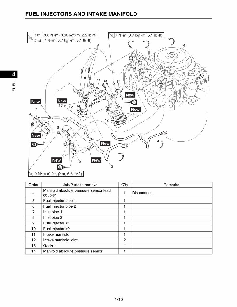
4-10
1
2
3
4
5
6
7
8
9
10
FU
EL
FUEL INJECTORS AND INTAKE MANIFOLD
Order Job/Parts to remove Q’ty Remarks
4Manifold absolute pressure sensor lead coupler
1 Disconnect.
5 Fuel injector pipe 1 1
6 Fuel injector pipe 2 1
7 Inlet pipe 1 1
8 Inlet pipe 2 1
9 Fuel injector #1 1
10 Fuel injector #2 1
11 Intake manifold 1
12 Intake manifold joint 2
13 Gasket 4
14 Manifold absolute pressure sensor 1
4
5
6
7
89
10
11
12
1213
13
14
7 N・m (0.7 kgf・m, 5.1 lb・ft) 3.0 N・m (0.30 kgf・m, 2.2 lb・ft) 1st
2nd7 N・m (0.7 kgf・m, 5.1 lb・ft)
9 N・m (0.9 kgf・m, 6.5 lb・ft)

4-11
1
2
3
4
5
6
7
8
9
10
FU
EL
FUEL INJECTORS AND INTAKE MANIFOLD
REMOVING THE FUEL INJECTORSThe following procedure applies to all of the fuel injectorsand related components.
1. Remove:• Air filter case
(Refer to “AIR FILTER” on page 3-3)• ECU and rectifier/regulator
(Refer to “ECU, RECTIFIER/REGULATOR, ANDFUSES” on page 3-8)
• Low-pressure fuel pump(Refer to “FUEL PUMPS” on page 4-1)
• Oil cooler(Refer to “OIL COOLER” on page 3-5)
• Fan case and fan(Refer to “CASE AND FAN” on page 3-11)
• Throttle body assembly(Refer to “THROTTLE BODY ASSEMBLY” on page4-6)
• Ignition coil(Refer to “IGNITION COILS” on page 3-10)
2. Remove:• Hose clamp (Clic-R)
(Refer to “REMOVING THE OIL COOLER” on page3-6)
• Fuel injector pipe 1 “1”• Fuel injector pipe 2 “2”
3. Disconnect:• Fuel injector lead coupler
TIP
Slide the coupler cover “a” upward as shown in the illustra-tion, and remove the coupler.
1
2
aa
a

4-12
1
2
3
4
5
6
7
8
9
10
FU
EL
FUEL INJECTORS AND INTAKE MANIFOLD
4. Remove:• Fuel injector
TIP
Remove the fuel injector “1” with the inlet pipe “2” installed.
5. Remove:• Inlet pipe
TIP
After removing the retainer “1”, remove the inlet pipe “2”from the fuel injector.
6. Check:• Fuel injectors
Obstruction Replace and check the fuel pump/fuel supply system.Deposit Replace.Damage Replace.
7. Check:• Fuel injector resistance
(Refer to “CHECKING THE FUEL INJECTORS” onpage 5-35)
INSTALLING THE FUEL INJECTORSThe following procedure applies to all of the fuel injectorsand related components.
1. Install:• Fuel injector “1”• O-ring “2” • Inlet pipe “3”
1
2
1 2
1
3
2
2
New
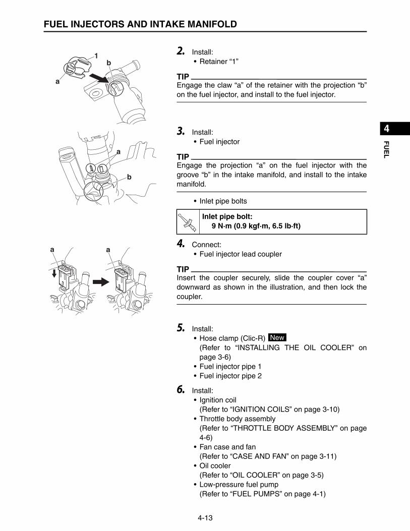
4-13
1
2
3
4
5
6
7
8
9
10
FU
EL
FUEL INJECTORS AND INTAKE MANIFOLD
2. Install:• Retainer “1”
TIP
Engage the claw “a” of the retainer with the projection “b”on the fuel injector, and install to the fuel injector.
3. Install:• Fuel injector
TIP
Engage the projection “a” on the fuel injector with thegroove “b” in the intake manifold, and install to the intakemanifold.
• Inlet pipe bolts
4. Connect:• Fuel injector lead coupler
TIP
Insert the coupler securely, slide the coupler cover “a”downward as shown in the illustration, and then lock thecoupler.
5. Install:• Hose clamp (Clic-R)
(Refer to “INSTALLING THE OIL COOLER” onpage 3-6)
• Fuel injector pipe 1• Fuel injector pipe 2
6. Install:• Ignition coil
(Refer to “IGNITION COILS” on page 3-10)• Throttle body assembly
(Refer to “THROTTLE BODY ASSEMBLY” on page4-6)
• Fan case and fan(Refer to “CASE AND FAN” on page 3-11)
• Oil cooler(Refer to “OIL COOLER” on page 3-5)
• Low-pressure fuel pump(Refer to “FUEL PUMPS” on page 4-1)
1
a
b
a
b
Inlet pipe bolt:9 N·m (0.9 kgf·m, 6.5 lb·ft)T
R..
a a
New
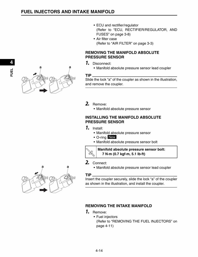
4-14
1
2
3
4
5
6
7
8
9
10
FU
EL
FUEL INJECTORS AND INTAKE MANIFOLD
• ECU and rectifier/regulator(Refer to “ECU, RECTIFIER/REGULATOR, ANDFUSES” on page 3-8)
• Air filter case(Refer to “AIR FILTER” on page 3-3)
REMOVING THE MANIFOLD ABSOLUTE PRESSURE SENSOR
1. Disconnect:• Manifold absolute pressure sensor lead coupler
TIP
Slide the lock “a” of the coupler as shown in the illustration,and remove the coupler.
2. Remove:• Manifold absolute pressure sensor
INSTALLING THE MANIFOLD ABSOLUTE PRESSURE SENSOR
1. Install:• Manifold absolute pressure sensor• O-ring • Manifold absolute pressure sensor bolt
2. Connect:• Manifold absolute pressure sensor lead coupler
TIP
Insert the coupler securely, slide the lock “a” of the coupleras shown in the illustration, and install the coupler.
REMOVING THE INTAKE MANIFOLD
1. Remove:• Fuel injectors
(Refer to “REMOVING THE FUEL INJECTORS” onpage 4-11)
aa
Manifold absolute pressure sensor bolt:7 N·m (0.7 kgf·m, 5.1 lb·ft)
New
TR..
a a

4-15
1
2
3
4
5
6
7
8
9
10
FU
EL
FUEL INJECTORS AND INTAKE MANIFOLD
2. Remove:• Intake manifold “1”• Intake manifold joints “2”• Gaskets “3”
CHECKING THE INTAKE MANIFOLD
1. Check:• Intake manifold• Intake manifold joints
Cracks/damage Replace.
INSTALLING THE INTAKE MANIFOLD
1. Install:• Gaskets “1” • Intake manifold joints “2”• Intake manifold “3”
2. Install:• Intake manifold nuts “1”–“4” and bolts “5”–“8”
TIP
Tighten the bolts and nuts to the specified torque in twosteps and in order from “1” to “8”.
3. Install:• Fuel injectors
(Refer to “INSTALLING THE FUEL INJECTORS”on page 4-12)
1
3
32
2
3
1
12
2
New
12
34
5
67
8
4
4 Intake manifold nut and bolt:1st: 3.0 N·m (0.30 kgf·m, 2.2 lb·ft)2nd: 7 N·m (0.7 kgf·m, 5.1 lb·ft)
TR..
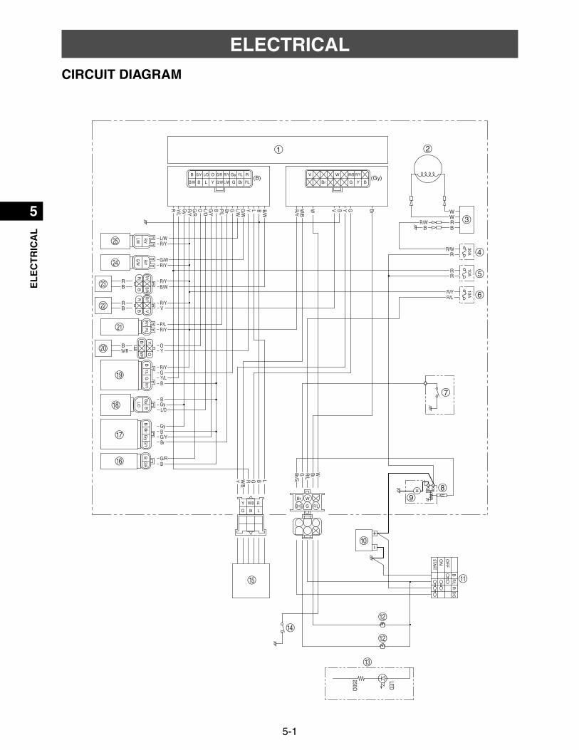
5-1
1
2
3
4
5
6
7
8
9
10
EL
EC
TR
ICA
L
ELECTRICALCIRCUIT DIAGRAM
W/R
Y
V
Br
250Ω
LED
(B) (Gy)
R/LW
GBr/GL
GY
BG
BrBV
RW/B
B
L
Y
B/WB
L/W
P/L
W/B
W
G/W
L/WGBrP/LBG
/Y
OG/R
Gy
RBGy
R/L
B
G/RB
O
R
B/WB
G
R
GyBG/YBr
G/W
R/W
R/WB
B
R
BRWW
Y
L/O
Y/L
L/O
R
R
Y/L
R/Y
R/Y
R/Y
R/Y
R/Y
R/Y
R/Y
R/Y
R/Y
Y
V W W/B
Br BGP/LBrGL/WG/WYLBB/W
RGyG/ROG/YB Y/LL/O R/YR/Y
P/LG
BG
/RY
L/W
O
BB
BW
/RB
r
G/W
BG
yG
/YB
Y/LG
yB/W
BV
L/OR
R
R/YR/Y
R/YR/Y
R/YR/Y
30A10A
10A
L
RW/B
B
Y
GR/LG
W
Br/G
Br
OF
F
ON
R/LR
BBr/G
START2
3
1
7
89
0
w
w
e
r
y
u
o
a
t
f
g
p
s
d
i
4
5
6
q

5-2
1
2
3
4
5
6
7
8
9
10
EL
EC
TR
ICA
LCIRCUIT DIAGRAM
Color code
1. ECU (Engine Control Unit) 14.Rollover switch2. Stator coil assembly 15.FI diagnostic tool coupler3. Rectifier/regulator 16.Engine temperature sensor4. Fuse (30 A) 17.Manifold absolute pressure sensor5. Fuse (10 A) 18.Throttle position sensor6. Fuse (10 A) 19.O2 sensor7. Oil pressure switch 20.Crankshaft position sensor8. Starter relay 21.High-pressure fuel pump9. Starter motor 22.Ignition coil #210.Battery 23.Ignition coil #111.Main switch 24.Fuel injector #112.Mil light 25.Fuel injector #213.Oil warning light
B Black G/R Green/Red
Br Brown G/W Green/White
G Green G/Y Green/Yellow
Gy Gray L/O Blue/Orange
L Blue L/W Blue/White
O Orange P/L Pink/Blue
R Red R/L Red/Blue
V Violet R/W Red/White
W White R/Y Red/Yellow
Y Yellow W/B White/Black
B/W Black/White W/R White/Red
Br/G Brown/Green Y/L Yellow/Blue
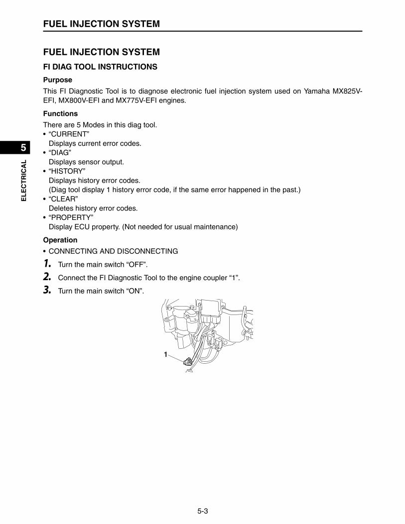
5-3
1
2
3
4
5
6
7
8
9
10
EL
EC
TR
ICA
LFUEL INJECTION SYSTEM
FUEL INJECTION SYSTEM
FI DIAG TOOL INSTRUCTIONS
Purpose
This FI Diagnostic Tool is to diagnose electronic fuel injection system used on Yamaha MX825V-EFI, MX800V-EFI and MX775V-EFI engines.
Functions
There are 5 Modes in this diag tool.• “CURRENT”
Displays current error codes.• “DIAG”
Displays sensor output.• “HISTORY”
Displays history error codes.(Diag tool display 1 history error code, if the same error happened in the past.)
• “CLEAR”Deletes history error codes.
• “PROPERTY”Display ECU property. (Not needed for usual maintenance)
Operation
• CONNECTING AND DISCONNECTING
1. Turn the main switch “OFF”.
2. Connect the FI Diagnostic Tool to the engine coupler “1”.
3. Turn the main switch “ON”.
1
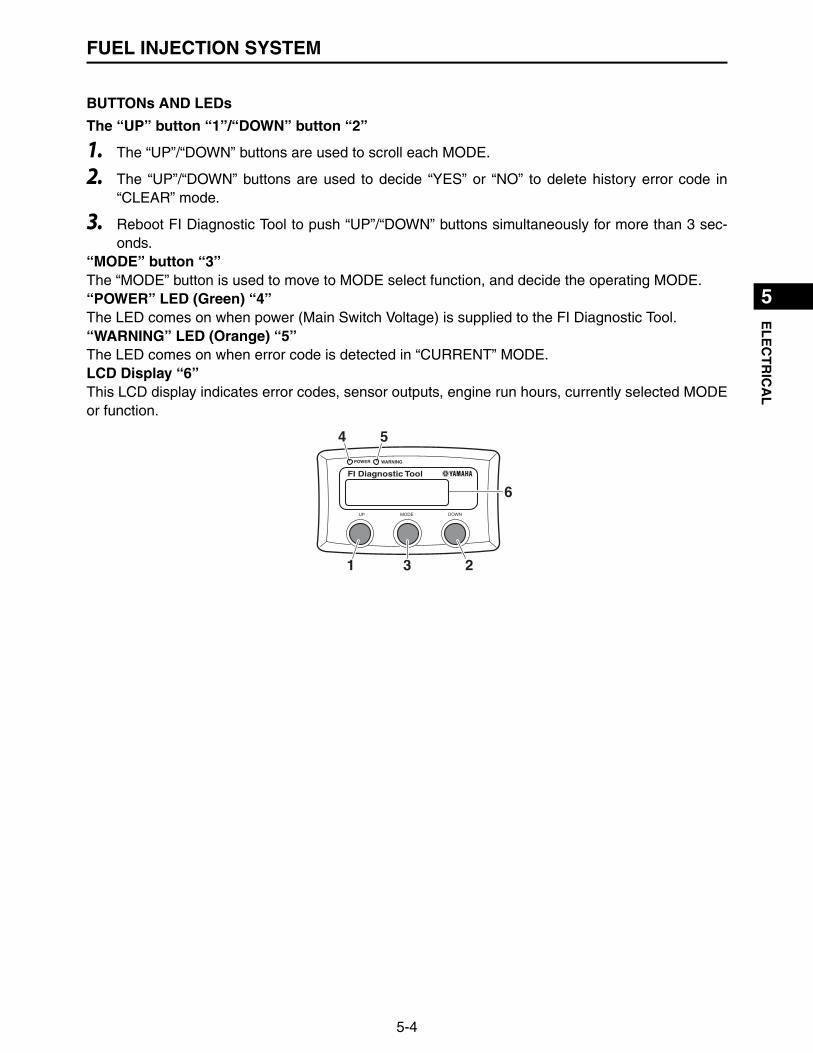
5-4
1
2
3
4
5
6
7
8
9
10
EL
EC
TR
ICA
LFUEL INJECTION SYSTEM
BUTTONs AND LEDs
The “UP” button “1”/“DOWN” button “2”
1. The “UP”/“DOWN” buttons are used to scroll each MODE.
2. The “UP”/“DOWN” buttons are used to decide “YES” or “NO” to delete history error code in“CLEAR” mode.
3. Reboot FI Diagnostic Tool to push “UP”/“DOWN” buttons simultaneously for more than 3 sec-onds.
“MODE” button “3”The “MODE” button is used to move to MODE select function, and decide the operating MODE.“POWER” LED (Green) “4”The LED comes on when power (Main Switch Voltage) is supplied to the FI Diagnostic Tool.“WARNING” LED (Orange) “5”The LED comes on when error code is detected in “CURRENT” MODE.LCD Display “6”This LCD display indicates error codes, sensor outputs, engine run hours, currently selected MODEor function.
6
31 2
54

5-5
1
2
3
4
5
6
7
8
9
10
EL
EC
TR
ICA
LFUEL INJECTION SYSTEM
Operation (BUTTONs and LEDs)
1. CONNECT 10.SELECT2. CONNECTED 11.CURRENT3. CHANGE MODE 12.SELECT4. (EACH) MODE 13.CURRENT5. DETERMINE MODE 14.DIAG6. FAILED 15.HISTORY7. Reboot (UP+DOWN) (Simultaneously more than 3
seconds)16.CLEAR
8. WAITING 17.PROPERTY9. COM ERROR
CODENO ERRORCOM ERROR
CODENO ERRORWAITING...
CURRENT
CURRENTDIAGHISTORYCLEARPROPERTY
DOWN
MODE
UP
SELECT
NO ERRORSELECT
1
2
3
4
5
6
7
151413
1716
11
8
9
10
12

5-6
1
2
3
4
5
6
7
8
9
10
EL
EC
TR
ICA
LFUEL INJECTION SYSTEM
Details
• “CURRENT” MODEDisplay when there is error
Display when there is no error
• “DIAG” MODE
1. Selected Mode 3. Total number of Error Code2. Error Code 4. Current page number on display
1. Selected Mode 2. Message
Diag Code Item What to display Unit
MAPManifold Absolute Pressure Sen-sor
Manifold Absolute Pressure psi
IAT Intake Air Temperature Sensor Intake Air Temperature F
ET Engine Temperature Sensor Engine Temperature F
TPS Throttle Position Sensor Throttle Valve position %
O2 O2 sensor Oxygen density V
RPM Engine rpm Engine rpm rpm
HOUR Engine run hour Engine run hour hr
P012201/02CURRENT 2
34
1
CODENO ERRORCURRENT
2
1

5-7
1
2
3
4
5
6
7
8
9
10
EL
EC
TR
ICA
LFUEL INJECTION SYSTEM
• “HISTORY” MODEDisplay when there is error code in the past
Display there is no error code in the past
1. Selected Mode 3. Unit2. Selected Diag Code 4. Sensor output
1. Selected Mode 3. Total number of Error Code2. Error Code 4. Current page number on display
1. Selected Mode 2. Message
psi14.7DIAG MAP
2
34
1
P012201/02HISTORY 2
34
1
CODENO ERRORHISTORY
2
1
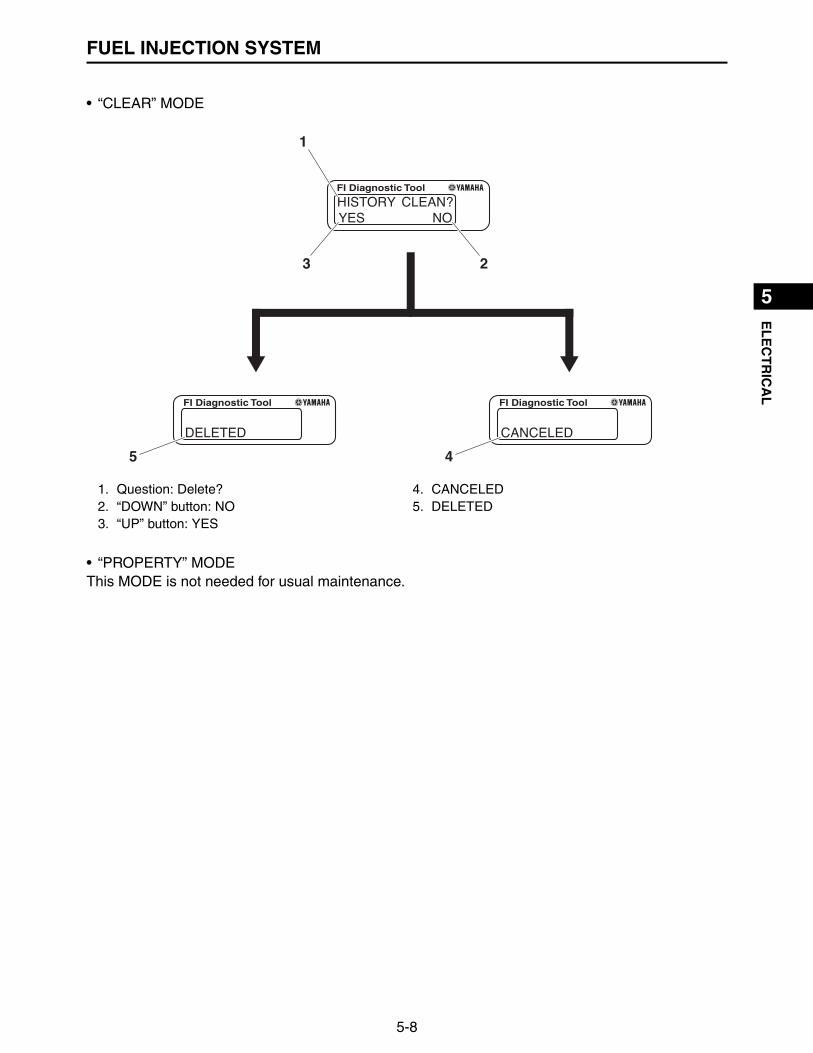
5-8
1
2
3
4
5
6
7
8
9
10
EL
EC
TR
ICA
LFUEL INJECTION SYSTEM
• “CLEAR” MODE
• “PROPERTY” MODEThis MODE is not needed for usual maintenance.
1. Question: Delete? 4. CANCELED2. “DOWN” button: NO 5. DELETED3. “UP” button: YES
NOYESHISTORY CLEAN?
DELETEDHISTORY
CANCELEDHISTORY
3 2
1
5 4

5-9
1
2
3
4
5
6
7
8
9
10
EL
EC
TR
ICA
LFUEL INJECTION SYSTEM
FUEL INJECTION DIAGRAM
1. Fuel filter 8. O2 sensor2. Fuel pump (low pressure) 9. Engine temperature sensor3. Fuel pump (high pressure) 10.Crankshaft position sensor4. Fuel injector 11.Throttle body5. ECU (Engine Control Unit) 12.Manifold absolute pressure sensor6. Throttle position sensor 13.Air filter case7. Ignition coil 14.Muffler
A. Fuel systemB. Air systemC. Control system
3
13B
11
12
10
9
8
A
4
5
C
7
6
14
21
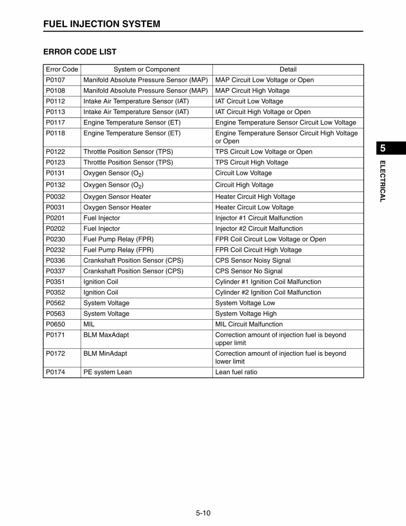
5-10
1
2
3
4
5
6
7
8
9
10
EL
EC
TR
ICA
LFUEL INJECTION SYSTEM
ERROR CODE LIST
Error Code System or Component Detail
P0107 Manifold Absolute Pressure Sensor (MAP) MAP Circuit Low Voltage or Open
P0108 Manifold Absolute Pressure Sensor (MAP) MAP Circuit High Voltage
P0112 Intake Air Temperature Sensor (IAT) IAT Circuit Low Voltage
P0113 Intake Air Temperature Sensor (IAT) IAT Circuit High Voltage or Open
P0117 Engine Temperature Sensor (ET) Engine Temperature Sensor Circuit Low Voltage
P0118 Engine Temperature Sensor (ET) Engine Temperature Sensor Circuit High Voltage or Open
P0122 Throttle Position Sensor (TPS) TPS Circuit Low Voltage or Open
P0123 Throttle Position Sensor (TPS) TPS Circuit High Voltage
P0131 Oxygen Sensor (O2) Circuit Low Voltage
P0132 Oxygen Sensor (O2) Circuit High Voltage
P0032 Oxygen Sensor Heater Heater Circuit High Voltage
P0031 Oxygen Sensor Heater Heater Circuit Low Voltage
P0201 Fuel Injector Injector #1 Circuit Malfunction
P0202 Fuel Injector Injector #2 Circuit Malfunction
P0230 Fuel Pump Relay (FPR) FPR Coil Circuit Low Voltage or Open
P0232 Fuel Pump Relay (FPR) FPR Coil Circuit High Voltage
P0336 Crankshaft Position Sensor (CPS) CPS Sensor Noisy Signal
P0337 Crankshaft Position Sensor (CPS) CPS Sensor No Signal
P0351 Ignition Coil Cylinder #1 Ignition Coil Malfunction
P0352 Ignition Coil Cylinder #2 Ignition Coil Malfunction
P0562 System Voltage System Voltage Low
P0563 System Voltage System Voltage High
P0650 MIL MIL Circuit Malfunction
P0171 BLM MaxAdapt Correction amount of injection fuel is beyond upper limit
P0172 BLM MinAdapt Correction amount of injection fuel is beyond lower limit
P0174 PE system Lean Lean fuel ratio

5-11
1
2
3
4
5
6
7
8
9
10
EL
EC
TR
ICA
LFUEL INJECTION SYSTEM
DIAG CODE LIST
DIAG Tool Mode
Diag Code
ItemWhat to dis-
playUnit How to diagnosis
DIAG
MAP
Manifold Absolute
Pressure sen-sor
Manifold Absolute Pressure
psi
• Compare the sensor output value with atmospheric absolute pressure (Exam-ple: 14.7 psi) with engine stopped.
• Confirm the sensor output value on dis-play changes while engine cranking.(Manifold Absolute pressure changes during cranking.)
IATIntake Air
Temperature Sensor
Intake Air Temperature
F
• Compare the sensor output value with ambient air temperature. (with engine cold)
• Confirm the sensor output value on dis-play changes with heating or cooling sen-sor alone.
ETEngine Tem-perature Sen-
sor
Engine Tem-perature
F
• Compare the sensor output value with ambient air temperature. (with engine cold)
• Confirm the sensor output value on dis-play changes with heating or cooling sen-sor alone.
• Sensor resistance: 9.0–11.0 k (25 C)
TPSThrottle Posi-tion Sensor
Throttle Valve position
%
• Confirm throttle position on FI diagnositc tool display when throttle valve is fully opened.MX825V: 95–100 %MX800V: 67–77 %MX775V: 54–64 %
• Confirm throttle position on FI diagnositc tool display when throttle valve is fully closed.MX825/800/775V: 0–5 %
• Confirm throttle position on display changes smoothly with throttle valve open and close.
O2 O2 sensor Oxygen den-sity
V —
RPM Engine rpm Engine rpm rpm —
HOUREngine run
hourEngine run
hourhr —
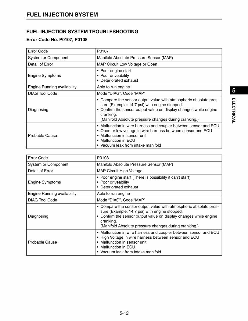
5-12
1
2
3
4
5
6
7
8
9
10
EL
EC
TR
ICA
LFUEL INJECTION SYSTEM
FUEL INJECTION SYSTEM TROUBLESHOOTING
Error Code No. P0107, P0108
Error Code P0107
System or Component Manifold Absolute Pressure Sensor (MAP)
Detail of Error MAP Circuit Low Voltage or Open
Engine Symptoms• Poor engine start• Poor driveability• Deteriorated exhaust
Engine Running availability Able to run engine
DIAG Tool Code Mode “DIAG”, Code “MAP”
Diagnosing
• Compare the sensor output value with atmospheric absolute pres-sure (Example: 14.7 psi) with engine stopped.
• Confirm the sensor output value on display changes while engine cranking.(Manifold Absolute pressure changes during cranking.)
Probable Cause
• Malfunction in wire harness and coupler between sensor and ECU• Open or low voltage in wire harness between sensor and ECU• Malfunction in sensor unit• Malfunction in ECU• Vacuum leak from intake manifold
Error Code P0108
System or Component Manifold Absolute Pressure Sensor (MAP)
Detail of Error MAP Circuit High Voltage
Engine Symptoms• Poor engine start (There is possibility it can’t start)• Poor driveability• Deteriorated exhaust
Engine Running availability Able to run engine
DIAG Tool Code Mode “DIAG”, Code “MAP”
Diagnosing
• Compare the sensor output value with atmospheric absolute pres-sure (Example: 14.7 psi) with engine stopped.
• Confirm the sensor output value on display changes while engine cranking.(Manifold Absolute pressure changes during cranking.)
Probable Cause
• Malfunction in wire harness and coupler between sensor and ECU• High Voltage in wire harness between sensor and ECU• Malfunction in sensor unit• Malfunction in ECU• Vacuum leak from intake manifold
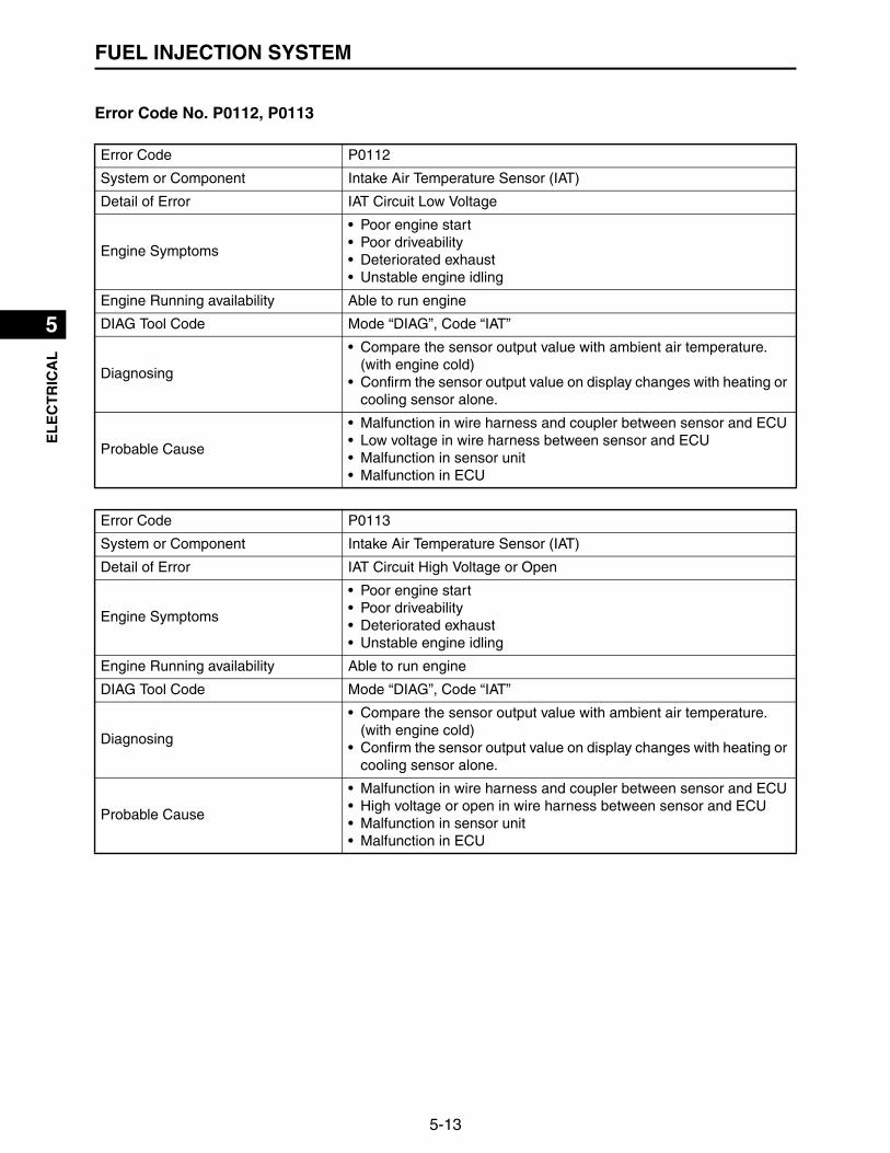
5-13
1
2
3
4
5
6
7
8
9
10
EL
EC
TR
ICA
LFUEL INJECTION SYSTEM
Error Code No. P0112, P0113
Error Code P0112
System or Component Intake Air Temperature Sensor (IAT)
Detail of Error IAT Circuit Low Voltage
Engine Symptoms
• Poor engine start• Poor driveability• Deteriorated exhaust• Unstable engine idling
Engine Running availability Able to run engine
DIAG Tool Code Mode “DIAG”, Code “IAT”
Diagnosing
• Compare the sensor output value with ambient air temperature. (with engine cold)
• Confirm the sensor output value on display changes with heating or cooling sensor alone.
Probable Cause
• Malfunction in wire harness and coupler between sensor and ECU• Low voltage in wire harness between sensor and ECU• Malfunction in sensor unit• Malfunction in ECU
Error Code P0113
System or Component Intake Air Temperature Sensor (IAT)
Detail of Error IAT Circuit High Voltage or Open
Engine Symptoms
• Poor engine start• Poor driveability• Deteriorated exhaust• Unstable engine idling
Engine Running availability Able to run engine
DIAG Tool Code Mode “DIAG”, Code “IAT”
Diagnosing
• Compare the sensor output value with ambient air temperature. (with engine cold)
• Confirm the sensor output value on display changes with heating or cooling sensor alone.
Probable Cause
• Malfunction in wire harness and coupler between sensor and ECU• High voltage or open in wire harness between sensor and ECU• Malfunction in sensor unit• Malfunction in ECU
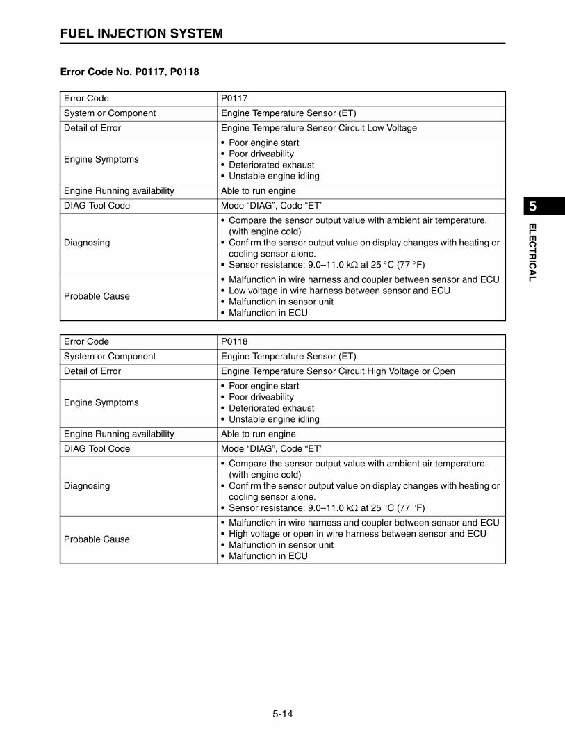
5-14
1
2
3
4
5
6
7
8
9
10
EL
EC
TR
ICA
LFUEL INJECTION SYSTEM
Error Code No. P0117, P0118
Error Code P0117
System or Component Engine Temperature Sensor (ET)
Detail of Error Engine Temperature Sensor Circuit Low Voltage
Engine Symptoms
• Poor engine start• Poor driveability• Deteriorated exhaust• Unstable engine idling
Engine Running availability Able to run engine
DIAG Tool Code Mode “DIAG”, Code “ET”
Diagnosing
• Compare the sensor output value with ambient air temperature. (with engine cold)
• Confirm the sensor output value on display changes with heating or cooling sensor alone.
• Sensor resistance: 9.0–11.0 k at 25 C (77 F)
Probable Cause
• Malfunction in wire harness and coupler between sensor and ECU• Low voltage in wire harness between sensor and ECU• Malfunction in sensor unit• Malfunction in ECU
Error Code P0118
System or Component Engine Temperature Sensor (ET)
Detail of Error Engine Temperature Sensor Circuit High Voltage or Open
Engine Symptoms
• Poor engine start• Poor driveability• Deteriorated exhaust• Unstable engine idling
Engine Running availability Able to run engine
DIAG Tool Code Mode “DIAG”, Code “ET”
Diagnosing
• Compare the sensor output value with ambient air temperature. (with engine cold)
• Confirm the sensor output value on display changes with heating or cooling sensor alone.
• Sensor resistance: 9.0–11.0 k at 25 C (77 F)
Probable Cause
• Malfunction in wire harness and coupler between sensor and ECU• High voltage or open in wire harness between sensor and ECU• Malfunction in sensor unit• Malfunction in ECU

5-15
1
2
3
4
5
6
7
8
9
10
EL
EC
TR
ICA
LFUEL INJECTION SYSTEM
Error Code No. P0122, P0123
Error Code P0122
System or Component Throttle Position Sensor (TPS)
Detail of Error TPS Circuit Low Voltage or Open
Engine Symptoms
• Poor engine start (There is possibility it can’t start)• Poor driveability• Deteriorated exhaust• Unstable engine idling (Different idling engine rpm)• Limited engine performance
Engine Running availability Able to run engine
DIAG Tool Code Mode “DIAG”, Code “TPS”
Diagnosing
• Confirm throttle position on FI diagnostic tool display when throttle valve is fully opened.MX825V: 95–100 %MX800V: 67–77 %MX775V: 54–64 %
• Confirm throttle position on FI diagnostic tool display when throttle valve is fully closed.MX825/800/775V: 0–5 %
• Confirm throttle position on display changes smoothly with throttle valve open and close.
Probable Cause
• Malfunction in wire harness and coupler between sensor and ECU• Low voltage or open in wire harness between sensor and ECU• Malfunction in sensor unit• Malfunction in ECU
Error Code P0123
System or Component Throttle Position Sensor (TPS)
Detail of Error TPS Circuit High Voltage
Engine Symptoms
• Poor engine start (There is possibility it can’t start)• Poor driveability• Deteriorated exhaust• Unstable engine idling (Different idling engine rpm)• Limited engine performance
Engine Running availability Able to run engine
DIAG Tool Code Mode “DIAG”, Code “TPS”
Diagnosing
• Confirm throttle position on FI diagnostic tool display when throttle valve is fully opened.MX825V: 95–100 %MX800V: 67–77 %MX775V: 54–64 %
• Confirm throttle position on FI diagnostic tool display when throttle valve is fully closed.MX825/800/775V: 0–5 %
• Confirm throttle position on display changes smoothly with throttle valve open and close.
Probable Cause
• Malfunction in wire harness and coupler between sensor and ECU• Low voltage or open in wire harness between sensor and ECU• Malfunction in sensor unit• Malfunction in ECU

5-16
1
2
3
4
5
6
7
8
9
10
EL
EC
TR
ICA
LFUEL INJECTION SYSTEM
Error Code No. P0131, P0132
Error Code P0131
System or Component Oxygen Sensor
Detail of Error Circuit Low Voltage
Engine Symptoms Deteriorated exhaust
Engine Running availability Able to run engine
DIAG Tool Code Mode “DIAG”, Code “O2”
Diagnosing —
Probable Cause
• Malfunction in wire harness and coupler between sensor and ECU• Low voltage in wire harness between sensor and ECU• Malfunction in sensor unit• Malfunction in ECU
Error Code P0132
System or Component Oxygen Sensor
Detail of Error Circuit High Voltage
Engine Symptoms Deteriorated exhaust
Engine Running availability Able to run engine
DIAG Tool Code Mode “DIAG”, Code “O2”
Diagnosing —
Probable Cause
• Malfunction in wire harness and coupler between sensor and ECU• High voltage in wire harness between sensor and ECU• Malfunction in sensor unit• Malfunction in ECU
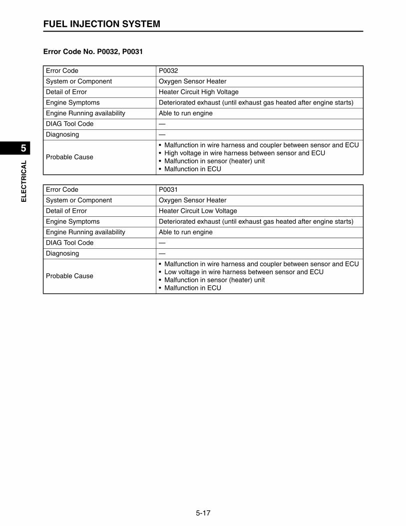
5-17
1
2
3
4
5
6
7
8
9
10
EL
EC
TR
ICA
LFUEL INJECTION SYSTEM
Error Code No. P0032, P0031
Error Code P0032
System or Component Oxygen Sensor Heater
Detail of Error Heater Circuit High Voltage
Engine Symptoms Deteriorated exhaust (until exhaust gas heated after engine starts)
Engine Running availability Able to run engine
DIAG Tool Code —
Diagnosing —
Probable Cause
• Malfunction in wire harness and coupler between sensor and ECU• High voltage in wire harness between sensor and ECU• Malfunction in sensor (heater) unit• Malfunction in ECU
Error Code P0031
System or Component Oxygen Sensor Heater
Detail of Error Heater Circuit Low Voltage
Engine Symptoms Deteriorated exhaust (until exhaust gas heated after engine starts)
Engine Running availability Able to run engine
DIAG Tool Code —
Diagnosing —
Probable Cause
• Malfunction in wire harness and coupler between sensor and ECU• Low voltage in wire harness between sensor and ECU• Malfunction in sensor (heater) unit• Malfunction in ECU

5-18
1
2
3
4
5
6
7
8
9
10
EL
EC
TR
ICA
LFUEL INJECTION SYSTEM
Error Code No. P0201, P0202
Error Code P0201
System or Component Fuel Injector
Detail of Error Injector #1 Circuit Malfunction
Engine Symptoms Cylinder #1 stops
Engine Running availability Able to run with Cylinder #2 alone
DIAG Tool Code —
DiagnosingFuel injector resistance11.4–12.6
Probable Cause
• Malfunction in wire harness and coupler between injector and ECU• Shorted or open in wire harness between sensor and ECU• Malfunction in injector• Malfunction in ECU
Error Code P0202
System or Component Fuel Injector
Detail of Error Injector #2 Circuit Malfunction
Engine Symptoms Cylinder #2 stops
Engine Running availability Able to run with Cylinder #1 alone
DIAG Tool Code —
DiagnosingFuel injector resistance11.4–12.6
Probable Cause
• Malfunction in wire harness and coupler between injector and ECU• Shorted or open in wire harness between sensor and ECU• Malfunction in injector• Malfunction in ECU

5-19
1
2
3
4
5
6
7
8
9
10
EL
EC
TR
ICA
LFUEL INJECTION SYSTEM
Error Code No. P0230, P0232
Error Code P0230
System or Component Fuel Pump Relay (FPR)
Detail of Error FPR Coil Circuit Low Voltage or Open
Engine Symptoms• Engine stop• Unable to start engine
Engine Running availability Unable to run engine
DIAG Tool Code —
Diagnosing —
Probable Cause
• Malfunction in wire harness and coupler between pump and ECU• Low voltage or open in wire harness between pump and ECU• Malfunction in pump• Malfunction in ECU
Error Code P0232
System or Component Fuel Pump Relay (FPR)
Detail of Error FPR Coil Circuit High Voltage
Engine Symptoms• Engine stop• Unable to start engine
Engine Running availability Unable to run engine
DIAG Tool Code —
Diagnosing —
Probable Cause
• Malfunction in wire harness and coupler between pump and ECU• High voltage in wire harness between pump and ECU• Malfunction in pump• Malfunction in ECU

5-20
1
2
3
4
5
6
7
8
9
10
EL
EC
TR
ICA
LFUEL INJECTION SYSTEM
Error Code No. P0336, P0337
Error Code P0336
System or Component Crankshaft Position Sensor (CPS)
Detail of Error CPS Sensor Noisy Signal
Engine Symptoms
• Poor engine start (There is possibility it can’t start)• Poor driveability• Deteriorated exhaust• Unstable engine idling
Engine Running availability Depends on the case
DIAG Tool Code —
DiagnosingCrankshaft position sensor resistance3.0–7.0 k
Probable Cause
• Malfunction in wire harness and coupler between sensor and ECU• Malfunction in sensor installing (loose sensor, dirty sensor, air gap)• Malfunction in sensor unit• Malfunction in ECU• Malfunction in rotor (damaged, deformed)
Error Code P0337
System or Component Crankshaft Position Sensor (CPS)
Detail of Error CPS Sensor No Signal
Engine Symptoms
• Poor engine start (There is possibility it can’t start)• Poor driveability• Deteriorated exhaust• Unstable engine idling
Engine Running availability Depends on the case
DIAG Tool Code —
DiagnosingCrankshaft position sensor resistance3.0–7.0 k
Probable Cause
• Malfunction in wire harness and coupler between sensor and ECU• Shorted or open in wire harness between sensor and ECU• Malfunction in sensor installing (loose sensor, dirty sensor, air gap)• Malfunction in sensor unit• Malfunction in ECU• Malfunction in rotor (damaged, deformed)

5-21
1
2
3
4
5
6
7
8
9
10
EL
EC
TR
ICA
LFUEL INJECTION SYSTEM
Error Code No. P0351, P0352
Error Code P0351
System or Component Ignition Coil
Detail of Error Cylinder #1 Ignition Coil Malfunction
Engine Symptoms Cylinder #1 stops operating (Injector also stops operating.)
Engine Running availability Able to run with Cylinder #2 alone
DIAG Tool Code —
Diagnosing
• Primary coil resistance0.44–0.66
• Secondary coil resistance5.6–8.4
Probable Cause
• Malfunction in wire harness and coupler between coil and ECU• Shorted or open in wire harness between coil and ECU• Malfunction in coil• Malfunction in ECU
Error Code P0352
System or Component Ignition Coil
Detail of Error Cylinder #2 Ignition Coil Malfunction
Engine Symptoms Cylinder #2 stops operating (Injector also stops operating)
Engine Running availability Able to run with Cylinder #1 alone
DIAG Tool Code —
Diagnosing
• Primary coil resistance0.44–0.66
• Secondary coil resistance5.6–8.4
Probable Cause
• Malfunction in wire harness and coupler between coil and ECU• Shorted or open in wire harness between coil and ECU• Malfunction in coil• Malfunction in ECU

5-22
1
2
3
4
5
6
7
8
9
10
EL
EC
TR
ICA
LFUEL INJECTION SYSTEM
Error Code No. P0562, P0563
Error Code P0562
System or Component System Voltage
Detail of Error System Voltage Low
Engine Symptoms• Engine stop• Unable to start engine
Engine Running availability Depends on the case
DIAG Tool Code —
Diagnosing Confirm battery voltage
Probable Cause
• Malfunction in wire harness and coupler between battery and ECU• Shorted or open in wire harness between battery and ECU• Malfunction in battery• Malfunction in charging system• Malfunction in ECU
Error Code P0563
System or Component System Voltage
Detail of Error System Voltage High
Engine Symptoms• Engine stop• Unable to start engine
Engine Running availability Depends on the case
DIAG Tool Code —
Diagnosing Confirm battery voltage
Probable Cause
• Malfunction in wire harness and coupler between battery and ECU• Shorted or open in wire harness between battery and ECU• Malfunction in battery• Malfunction in charging system• Malfunction in ECU

5-23
1
2
3
4
5
6
7
8
9
10
EL
EC
TR
ICA
LFUEL INJECTION SYSTEM
Error Code No. P0171, P0172, P0174
Error Code P0171
System or Component BLM MaxAdapt
Detail of Error Correction amount of injection fuel is beyond upper limit
Engine Symptoms
• Poor engine start (There is possibility it can’t start)• Poor driveability• Deteriorated exhaust• Unstable engine idling (Different idling engine rpm)
Engine Running availability Able to run engine
DIAG Tool Code —
Diagnosing —
Probable Cause
• Fuel system malfunction (Clogged fuel filter/line, fuel injector, fuel pump)
• Malfunction in O2 sensor• Malfunction in manifold absolute pressure sensor• Difference of actual intake air volume (Intake air leak, clogged man-
ifold, dirty/restricted air filter)• Malfunction in ECU• Malfunction in wiring harness
Error Code P0172
System or Component BLM MinAdapt
Detail of Error Correction amount of injection fuel is beyond lower limit
Engine Symptoms
• Poor engine start (There is possibility it can’t start)• Poor driveability• Deteriorated exhaust• Unstable engine idling (Different idling engine rpm)• Overheat• Engine knock sound
Engine Running availability Able to run engine
DIAG Tool Code —
Diagnosing —
Probable Cause
• Fuel system malfunction (Clogged fuel filter/line, fuel injector, fuel pump)
• Malfunction in O2 sensor• Malfunction in manifold absolute pressure sensor• Difference of actual intake air volume (Intake air leak, clogged man-
ifold, dirty/restricted air filter)• Malfunction in ECU• Malfunction in wiring harness

5-24
1
2
3
4
5
6
7
8
9
10
EL
EC
TR
ICA
LFUEL INJECTION SYSTEM
Error Code P0174
System or Component PE system Lean
Detail of Error Lean fuel ratio
Engine Symptomes
• Poor drivability• Deteriorated exhaust• Unstable engine idling (Different idling engine rpm)• Overheat• Engine knock sound
Engine Running availability Able to run engine
DIAG Tool Code —
How to Diagnosis —
Probable Cause
• Fuel system malfunction (Clogged fuel filter/line, fuel injector, fuel pump)
• Malfunction in O2 sensor• Malfunction in manifold absolute pressure sensor• Difference of actual intake air volume (Intake air leak/clogged man-
ifold)• Running out fuel

5-25
1
2
3
4
5
6
7
8
9
10
EL
EC
TR
ICA
LELECTRICAL COMPONENTS
ELECTRICAL COMPONENTS
1
2
2
3
45
6
6
7
89
10
11
12
13
14

5-26
1
2
3
4
5
6
7
8
9
10
EL
EC
TR
ICA
LELECTRICAL COMPONENTS
1. Manifold absolute pressure sensor2. Fuel injector3. Engine temperature sensor4. High-pressure fuel pump5. Oil pressure switch6. Ignition coil/spark plug cap7. Stator coil assembly8. Rectifier/regulator9. Crankshaft position sensor10.Throttle position sensor11.O2 sensor12.ECU (Engine Control Unit)13.Fuse14.Starter motor

5-27
1
2
3
4
5
6
7
8
9
10
EL
EC
TR
ICA
LELECTRICAL COMPONENTS
CHECKING THE SWITCH CONTINUITYCheck each switch for continuity with the tester. If the con-tinuity reading is incorrect, check the wiring connectionsand if necessary, replace the switch.
TIP
• Before checking for continuity, set the digital circuit testerto the “” range.
• When checking for continuity, switch back and forthbetween the switch positions a few times.
CHECKING THE FUSESThe following procedure applies to all of the fuses.
1. Remove:• Fuse “1”
2. Check:• Fuse
▼▼▼▼▼▼▼▼▼▼▼▼▼▼▼▼▼▼▼▼▼▼▼▼▼▼▼▼▼▼▼▼▼▼▼▼▼▼▼▼▼
a. Connect the digital circuit tester to the fuse andcheck the continuity.
Ω”
”
O.L”
”
Never insert the tester probes into the coupler termi-nal slots. Always insert the probes from the oppositeend of the coupler, taking care not to loosen or dam-age the leads.
Model 88 Multimeter with tachometer:YU-A1927
NOTICE
To avoid a short circuit, always set the main switch to“OFF” when checking or replacing a fuse.
NOTICE

5-28
1
2
3
4
5
6
7
8
9
10
EL
EC
TR
ICA
LELECTRICAL COMPONENTS
TIP
Set the digital circuit tester selector to “”.
b. If the digital circuit tester indicates “O.L”, replace thefuse.
▲▲▲▲▲▲▲▲▲▲▲▲▲▲▲▲▲▲▲▲▲▲▲▲▲▲▲▲▲▲▲▲▲▲▲▲▲▲▲▲▲
3. Replace:• Blown fuse
▼▼▼▼▼▼▼▼▼▼▼▼▼▼▼▼▼▼▼▼▼▼▼▼▼▼▼▼▼▼▼▼▼▼▼▼▼▼▼▼▼
a. Set the main switch to “OFF”.b. Install a new fuse of the correct amperage.c. Set the main switch to “ON” and verify if the electri-
cal circuit is operational.d. If the fuse immediately blows again, check the elec-
trical circuit.
▲▲▲▲▲▲▲▲▲▲▲▲▲▲▲▲▲▲▲▲▲▲▲▲▲▲▲▲▲▲▲▲▲▲▲▲▲▲▲▲▲
4. Install:• Fuse
CHECKING THE OIL PRESSURE SWITCH
1. Drain:• Engine oil
2. Disconnect:• Oil pressure switch lead
Model 88 Multimeter with tachometer:YU-A1927
ba
Fuse amperage “a”:30 A 1
Fuse amperage “b”:10 A 2
Never use a fuse with an amperage other than thatspecified. Improvising or using a fuse with the wrongamperage rating may cause extensive damage to theelectrical system and could possibly cause a fire.
WARNING

5-29
1
2
3
4
5
6
7
8
9
10
EL
EC
TR
ICA
LELECTRICAL COMPONENTS
3. Connect:• Digital circuit tester
(between the engine ground and oil pressure switchterminal)
4. Check:• Oil pressure switch continuity
No continuity Replace the oil pressure switch.
CHECKING MANIFOLD ABSOLUTE PRESSURE SENSOR
1. Connect:• FI Diagnostic Tool “1”
2. Select Mode:• Select “DIAG” Mode and “MAP” Diag Code.
3. Check:• Compare “MAP” value with atomosphere pressure
Does not much Replace the manifold absolute.
CHECKING THE THROTTLE POSITION SENSOR
1. Remove:• Throttle body assembly
(Refer to “THROTTLE BODY ASSEMBLY” on page4-6)
2. Check:• Throttle position sensor maximum resistance
Out of specification Replace the throttle positionsensor.
Model 88 Multimeter with tachometer:YU-A1927
1FI Diagnostic Tool:
90890-03253
Atomosphere pressure (Reference):14–15 Psi
• Handle the throttle body assembly with special care.• Never subject the throttle body assembly to strong
shocks. If the throttle body assembly is dropped,replace it.
NOTICE
5-30
1
2
3
4
5
6
7
8
9
10
EL
EC
TR
ICA
LELECTRICAL COMPONENTS
▼▼▼▼▼▼▼▼▼▼▼▼▼▼▼▼▼▼▼▼▼▼▼▼▼▼▼▼▼▼▼▼▼▼▼▼▼▼▼▼▼
a. Connect the digital circuit tester () to the throttleposition sensor terminals as shown.
b. Measure the throttle position sensor maximumresistance.
▲▲▲▲▲▲▲▲▲▲▲▲▲▲▲▲▲▲▲▲▲▲▲▲▲▲▲▲▲▲▲▲▲▲▲▲▲▲▲▲▲
3. Install:• Throttle body assembly
CHECKING THE CRANKSHAFT POSITION SENSOR
1. Remove:• Fan case cover• Grass screen• Fan case
(Refer to “CASE AND FAN” on page 3-11)
2. Check:• Crankshaft position sensor resistance
Out of specification Replace the crankshaft posi-tion sensor.
▼▼▼▼▼▼▼▼▼▼▼▼▼▼▼▼▼▼▼▼▼▼▼▼▼▼▼▼▼▼▼▼▼▼▼▼▼▼▼▼▼
a. Connect the digital circuit tester () to the crank-shaft position sensor coupler as shown.
Resistance:3.0–7.0 k
Model 88 Multimeter with tachometer:YU-A1927
a b• Positive tester probe
Terminal “a”• Negative tester probe
Terminal “b”
Crankshaft position sensor resistance:3.0–7.0 k
Model 88 Multimeter with tachometer:YU-A1927

5-31
1
2
3
4
5
6
7
8
9
10
EL
EC
TR
ICA
LELECTRICAL COMPONENTS
b. Measure the crankshaft position sensor resistance.▲▲▲▲▲▲▲▲▲▲▲▲▲▲▲▲▲▲▲▲▲▲▲▲▲▲▲▲▲▲▲▲▲▲▲▲▲▲▲▲▲
CHECKING THE ENGINE TEMPERATURE SENSOR
1. Remove:• Engine temperature sensor
2. Check:• Engine temperature sensor resistance
Out of specification Replace.
▼▼▼▼▼▼▼▼▼▼▼▼▼▼▼▼▼▼▼▼▼▼▼▼▼▼▼▼▼▼▼▼▼▼▼▼▼▼▼▼▼
a. Connect the digital circuit tester () to the enginetemperature sensor as shown.
b. Immerse the engine temperature sensor “1” in acontainer filled with water “2”.
TIP
Make sure the engine temperature sensor terminals do notget wet.
c. Place a thermometer “3” in the water.d. Slowly heat the water, then let it cool down to the
specified temperature.
1
2
• Positive tester probe White/Red “1” (wire harness color)
• Negative tester probe Black “2” (wire harness color)
• Handle the engine temperature sensor with specialcare.
• Never subject the engine temperature sensor tostrong shocks. If the engine temperature sensor isdropped, replace it.
Use inch tool “5/8” or 16 mm for engine temperaturesensor.
WARNING
NOTICE
Engine temperature sensor resistance:9.0–11.0 k at 25 C (77 F)
3 1
2
Model 88 Multimeter with tachometer:YU-A1927

5-32
1
2
3
4
5
6
7
8
9
10
EL
EC
TR
ICA
LELECTRICAL COMPONENTS
e. Measure the engine temperature sensor resis-tance.
▲▲▲▲▲▲▲▲▲▲▲▲▲▲▲▲▲▲▲▲▲▲▲▲▲▲▲▲▲▲▲▲▲▲▲▲▲▲▲▲▲
3. Install:• Engine temperature sensor
CHECKING THE IGNITION COILSThe following procedure applies to all of the ignition coils.
1. Check:• Primary coil resistance
Out of specification Replace.
▼▼▼▼▼▼▼▼▼▼▼▼▼▼▼▼▼▼▼▼▼▼▼▼▼▼▼▼▼▼▼▼▼▼▼▼▼▼▼▼▼
a. Remove the ignition coil from the spark plug.b. Connect the digital circuit tester () to the ignition
coil as shown.
c. Measure the primary coil resistance.▲▲▲▲▲▲▲▲▲▲▲▲▲▲▲▲▲▲▲▲▲▲▲▲▲▲▲▲▲▲▲▲▲▲▲▲▲▲▲▲▲
2. Check:• Secondary coil resistance
Out of specification Replace.
▼▼▼▼▼▼▼▼▼▼▼▼▼▼▼▼▼▼▼▼▼▼▼▼▼▼▼▼▼▼▼▼▼▼▼▼▼▼▼▼▼
a. Connect the digital circuit tester () to the ignitioncoil as shown.
Primary coil resistance:0.44–0.66
1
2
Model 88 Multimeter with tachometer:YU-A1927
• Positive tester probe Red “1” (wire harness color)
• Negative tester probe Black “2” (wire harness color)
Secondary coil resistance:5.6–8.4 k
Model 88 Multimeter with tachometer:YU-A1927

5-33
1
2
3
4
5
6
7
8
9
10
EL
EC
TR
ICA
LELECTRICAL COMPONENTS
b. Measure the secondary coil resistance.▲▲▲▲▲▲▲▲▲▲▲▲▲▲▲▲▲▲▲▲▲▲▲▲▲▲▲▲▲▲▲▲▲▲▲▲▲▲▲▲▲
CHECKING THE IGNITION SPARK GAPThe following procedure applies to all of the ignition coils.
1. Check:• Ignition spark gap
Out of specification Perform the ignition systemtroubleshooting, starting with step 5.(Refer to “IGNITION SYSTEM” on page 6-1)
TIP
If the ignition spark gap is within specification, the ignitionsystem circuit is operating normally.
▼▼▼▼▼▼▼▼▼▼▼▼▼▼▼▼▼▼▼▼▼▼▼▼▼▼▼▼▼▼▼▼▼▼▼▼▼▼▼▼▼
a. Disconnect the spark plug cap “1” from the sparkplug.
b. Connect the ignition checker “2” as shown.
c. Turn the main switch to “START”.d. Measure the ignition spark gap “a”.
▲▲▲▲▲▲▲▲▲▲▲▲▲▲▲▲▲▲▲▲▲▲▲▲▲▲▲▲▲▲▲▲▲▲▲▲▲▲▲▲▲
CHECKING THE SPARK PLUG CAPSThe following procedure applies to all of the spark plugcaps.
1. Remove:• Spark plug cap
2. Check:• Spark plug cap resistance
Out of specification Replace the spark plug cap.
1
2
• Positive tester probe Red “1” (wire harness color)
• Negative tester probe High-tension cord “2”
Minimum ignition spark gap:6.0 mm (0.236 in)
1
2
aIgnition checker:
90890-06754
Spark plug cap resistance:3.75–6.25 k
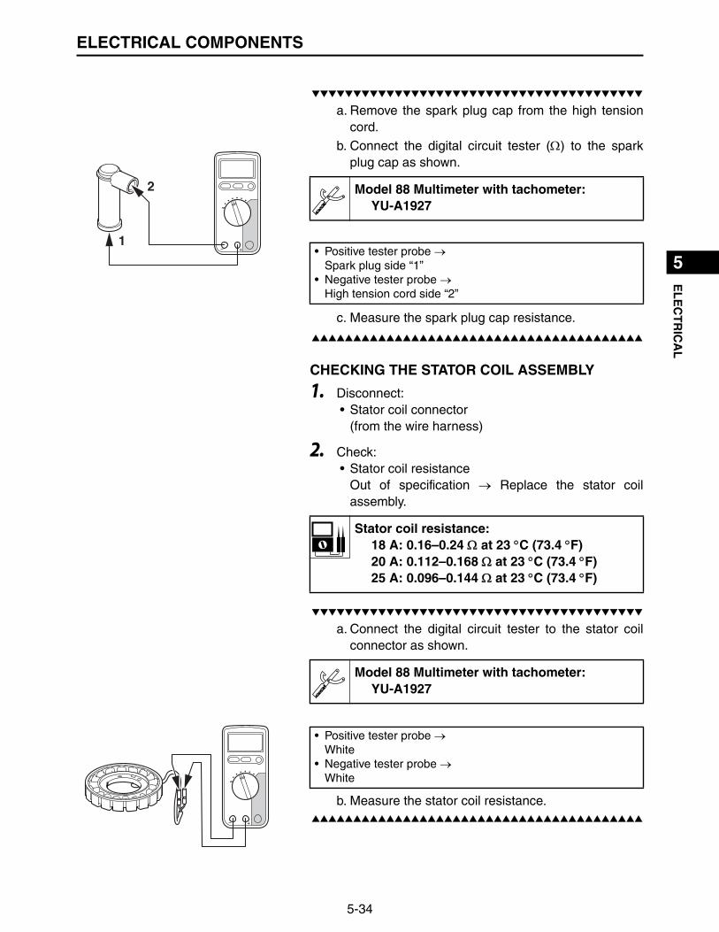
5-34
1
2
3
4
5
6
7
8
9
10
EL
EC
TR
ICA
LELECTRICAL COMPONENTS
▼▼▼▼▼▼▼▼▼▼▼▼▼▼▼▼▼▼▼▼▼▼▼▼▼▼▼▼▼▼▼▼▼▼▼▼▼▼▼▼▼
a. Remove the spark plug cap from the high tensioncord.
b. Connect the digital circuit tester () to the sparkplug cap as shown.
c. Measure the spark plug cap resistance.
▲▲▲▲▲▲▲▲▲▲▲▲▲▲▲▲▲▲▲▲▲▲▲▲▲▲▲▲▲▲▲▲▲▲▲▲▲▲▲▲▲
CHECKING THE STATOR COIL ASSEMBLY
1. Disconnect:• Stator coil connector
(from the wire harness)
2. Check:• Stator coil resistance
Out of specification Replace the stator coilassembly.
▼▼▼▼▼▼▼▼▼▼▼▼▼▼▼▼▼▼▼▼▼▼▼▼▼▼▼▼▼▼▼▼▼▼▼▼▼▼▼▼▼
a. Connect the digital circuit tester to the stator coilconnector as shown.
b. Measure the stator coil resistance.▲▲▲▲▲▲▲▲▲▲▲▲▲▲▲▲▲▲▲▲▲▲▲▲▲▲▲▲▲▲▲▲▲▲▲▲▲▲▲▲▲
1
2 Model 88 Multimeter with tachometer:YU-A1927
• Positive tester probe Spark plug side “1”
• Negative tester probe High tension cord side “2”
Stator coil resistance:18 A: 0.16–0.24 at 23 C (73.4 F)20 A: 0.112–0.168 at 23 C (73.4 F)25 A: 0.096–0.144 at 23 C (73.4 F)
Model 88 Multimeter with tachometer:YU-A1927
• Positive tester probe White
• Negative tester probe White
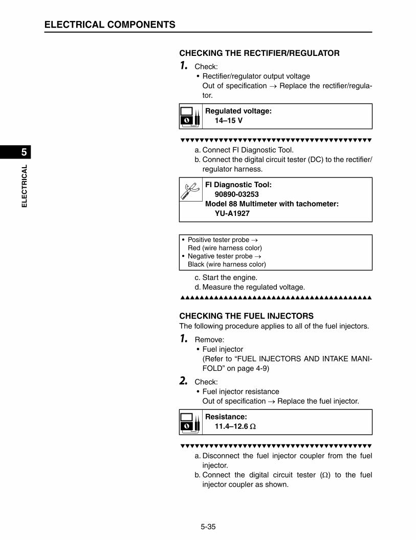
5-35
1
2
3
4
5
6
7
8
9
10
EL
EC
TR
ICA
LELECTRICAL COMPONENTS
CHECKING THE RECTIFIER/REGULATOR
1. Check:• Rectifier/regulator output voltage
Out of specification Replace the rectifier/regula-tor.
▼▼▼▼▼▼▼▼▼▼▼▼▼▼▼▼▼▼▼▼▼▼▼▼▼▼▼▼▼▼▼▼▼▼▼▼▼▼▼▼▼
a. Connect FI Diagnostic Tool.b. Connect the digital circuit tester (DC) to the rectifier/
regulator harness.
c. Start the engine.d. Measure the regulated voltage.
▲▲▲▲▲▲▲▲▲▲▲▲▲▲▲▲▲▲▲▲▲▲▲▲▲▲▲▲▲▲▲▲▲▲▲▲▲▲▲▲▲
CHECKING THE FUEL INJECTORSThe following procedure applies to all of the fuel injectors.
1. Remove:• Fuel injector
(Refer to “FUEL INJECTORS AND INTAKE MANI-FOLD” on page 4-9)
2. Check:• Fuel injector resistance
Out of specification Replace the fuel injector.
▼▼▼▼▼▼▼▼▼▼▼▼▼▼▼▼▼▼▼▼▼▼▼▼▼▼▼▼▼▼▼▼▼▼▼▼▼▼▼▼▼
a. Disconnect the fuel injector coupler from the fuelinjector.
b. Connect the digital circuit tester () to the fuelinjector coupler as shown.
Regulated voltage:14–15 V
FI Diagnostic Tool:90890-03253
Model 88 Multimeter with tachometer:YU-A1927
• Positive tester probe Red (wire harness color)
• Negative tester probe Black (wire harness color)
Resistance:11.4–12.6

5-36
1
2
3
4
5
6
7
8
9
10
EL
EC
TR
ICA
LELECTRICAL COMPONENTS
c. Measure the fuel injector resistance.▲▲▲▲▲▲▲▲▲▲▲▲▲▲▲▲▲▲▲▲▲▲▲▲▲▲▲▲▲▲▲▲▲▲▲▲▲▲▲▲▲
CHECKING THE STARTER MOTOR OPERATION
1. Check:• Starter motor operation
Does not operate Perform the electric startingsystem troubleshooting, starting with step 4.(Refer to “ELECTRIC STARTING SYSTEM” onpage 6-2)
▼▼▼▼▼▼▼▼▼▼▼▼▼▼▼▼▼▼▼▼▼▼▼▼▼▼▼▼▼▼▼▼▼▼▼▼▼▼▼▼▼
a. Connect the jumper lead “1” to the starter relay ter-minals on the battery side and the starter motorside.
b. Check the starter motor operation.c. Disconnect the main switch coupler.d. Connect the jumper lead “1” to the starter relay
coupler.e. Check the starter motor operation.
▲▲▲▲▲▲▲▲▲▲▲▲▲▲▲▲▲▲▲▲▲▲▲▲▲▲▲▲▲▲▲▲▲▲▲▲▲▲▲▲▲
Model 88 Multimeter with tachometer:YU-A1927
1
2• Positive tester probe
Injector terminal “1”• Negative tester probe
Injector terminal “2”
1
• A wire that is used as a jumper lead must have atleast the same capacity of the battery lead, other-wise the jumper lead may burn.
• This check is likely to produce sparks, therefore,make sure no flammable gas or fluid is in the vicin-ity.
WARNING
1

5-37
1
2
3
4
5
6
7
8
9
10
EL
EC
TR
ICA
LELECTRIC STARTING SYSTEM
ELECTRIC STARTING SYSTEM
REMOVING THE STARTER MOTOR
Order Job/Parts to remove Q’ty Remarks
Removing the starter motor Remove the parts in the order listed.
1 Starter relay terminals 1 Disconnect.
2 Earth terminal 1 Disconnect.
3 Starter motor assembly 1
1
2
3
9 N・m (0.9 kgf・m, 6.5 lb・ft)
23 N・m (2.3 kgf・m, 17 lb・ft)

5-38
1
2
3
4
5
6
7
8
9
10
EL
EC
TR
ICA
LELECTRIC STARTING SYSTEM
DISASSEMBLING THE STARTER MOTOR
Order Job/Parts to remove Q’ty Remarks
Disassembling the starter motor Disassemble the parts in the order listed.
1 Rear bracket 1
2 Insulator 1
3 Brush spring 4
4 Brush 4
5 Yoke 1
6 Armature 1
7 Starter relay 1
8 Starter drive lever 1
9 Starter case 1
1
2
34
5
6
7 8
9
11 N・m (1.1 kgf・m, 8.0 lb・ft)
9 N・m (0.9 kgf・m, 6.5 lb・ft)
6 N・m (0.6 kgf・m, 4.3 lb・ft)

5-39
1
2
3
4
5
6
7
8
9
10
EL
EC
TR
ICA
LELECTRIC STARTING SYSTEM
CHECKING THE ARMATURE COIL
1. Check:• Commutator (outer surface)
Dirty Clean it with #600 grit sandpaper.
2. Measure:• Mica (insulation depth between the commutator
segments)Out of specification Scrape the mica to theproper measurement using a hacksaw blade whichhas been grounded to fit the commutator.
TIP
The mica insulation of the commutator must be undercut toensure proper operation of the commutator.
3. Measure:• Armature coil (insulation/continuity)
Defects Replace the starter motor.Connect the digital circuit tester to the armaturecoil.
a
Depth of insulator “a”:2.0 mm (0.79 in)
Model 88 Multimeter with tachometer:YU-A1927
Commutator continuity:Continuity
Insulation resistance:More than 1.0 M
3
1
2
1. Continuity check2. Insulation check3. Armature coil
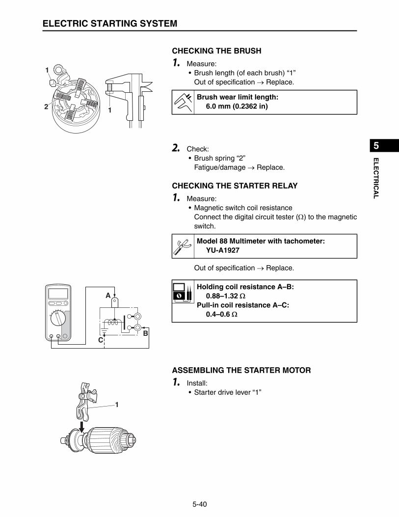
5-40
1
2
3
4
5
6
7
8
9
10
EL
EC
TR
ICA
LELECTRIC STARTING SYSTEM
CHECKING THE BRUSH
1. Measure:• Brush length (of each brush) “1”
Out of specification Replace.
2. Check:• Brush spring “2”
Fatigue/damage Replace.
CHECKING THE STARTER RELAY
1. Measure:• Magnetic switch coil resistance
Connect the digital circuit tester () to the magneticswitch.
Out of specification Replace.
ASSEMBLING THE STARTER MOTOR
1. Install:• Starter drive lever “1”
1
12Brush wear limit length:
6.0 mm (0.2362 in)
Model 88 Multimeter with tachometer:YU-A1927
A
BC
Holding coil resistance A–B:0.88–1.32
Pull-in coil resistance A–C:0.4–0.6
1

5-41
1
2
3
4
5
6
7
8
9
10
EL
EC
TR
ICA
LELECTRIC STARTING SYSTEM
2. Install:• Armature and starter drive lever “1”
3. Install:• Starter relay “1”
1
1Starter relay nut:
11 N·m (1.1 kgf·m, 8.0 lb·ft)TR..

1
2
3
4
5
6
7
8
9
10
TR
OU
BL
ES
HO
OT
ING
6-1
TROUBLESHOOTINGENGINE DOES NOT START
IGNITION SYSTEMThe ignition system fails to operate (no spark or intermittent spark).
No. Checking steps Possible remedy
1Check the fuses.(Refer to “CHECKING THE FUSES” on page 5-27)
Replace the fuse(s).
2 Check the battery.• Clean the battery terminals.• Recharge or replace the battery.
3Check the spark plugs.(Refer to “SPARK PLUGS” on page 2-2).
Re-gap or replace the spark plugs.
4Check the ignition spark gap.(Refer to “CHECKING THE IGNITION SPARK GAP” on page 5-33)
If the ignition spark gap is OK, the igni-tion system is OK.
5Check the ignition coils.(Refer to “CHECKING THE IGNITION COILS” on page 5-32)
Replace the ignition coils.
6Check the spark plug cap resistance.(Refer to “CHECKING THE SPARK PLUG CAPS” on page 5-33).
Replace the spark plug cap.
7Check the crankshaft position sensor.(Refer to “CHECKING THE CRANKSHAFT POSITION SENSOR” on page 5-30)
Replace the crankshaft position sensor.
8 Check the main switch. Replace the main switch.
9Check the entire ignition system’s wiring.(Refer to “CIRCUIT DIAGRAM” on page 5-1)
Properly connect or repair the ignition system’s wiring.
10 Replace the ECU. —
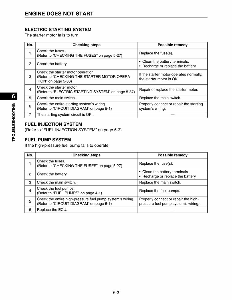
6-2
1
2
3
4
5
6
7
8
9
10
TR
OU
BL
ES
HO
OT
ING
ENGINE DOES NOT START
ELECTRIC STARTING SYSTEM The starter motor fails to turn.
FUEL INJECTION SYSTEM(Refer to “FUEL INJECTION SYSTEM” on page 5-3)
FUEL PUMP SYSTEMIf the high-pressure fuel pump fails to operate.
No. Checking steps Possible remedy
1Check the fuses.(Refer to “CHECKING THE FUSES” on page 5-27)
Replace the fuse(s).
2 Check the battery.• Clean the battery terminals.• Recharge or replace the battery.
3Check the starter motor operation.(Refer to “CHECKING THE STARTER MOTOR OPERA-TION” on page 5-36)
If the starter motor operates normally, the starter motor is OK.
4Check the starter motor.(Refer to “ELECTRIC STARTING SYSTEM” on page 5-37)
Repair or replace the starter motor.
5 Check the main switch. Replace the main switch.
6Check the entire starting system’s wiring.(Refer to “CIRCUIT DIAGRAM” on page 5-1)
Properly connect or repair the starting system’s wiring.
7 The starting system circuit is OK. —
No. Checking steps Possible remedy
1Check the fuses.(Refer to “CHECKING THE FUSES” on page 5-27)
Replace the fuse(s).
2 Check the battery.• Clean the battery terminals.• Recharge or replace the battery.
3 Check the main switch. Replace the main switch.
4Check the fuel pumps.(Refer to “FUEL PUMPS” on page 4-1)
Replace the fuel pumps.
5Check the entire high-pressure fuel pump system’s wiring.(Refer to “CIRCUIT DIAGRAM” on page 5-1)
Properly connect or repair the high-pressure fuel pump system’s wiring.
6 Replace the ECU. —

6-3
1
2
3
4
5
6
7
8
9
10
TR
OU
BL
ES
HO
OT
ING
OTHER TROUBLES
OTHER TROUBLES
ENGINE STARTS BUT STALLS
No. Checking steps Possible remedy
1 Check the fuel level. Add the fuel if it is insufficient.
2 Check if the fuel filter is clogged. Clean or replace.
3 Check if the fuel hoses is clogged. Clean.
4Check if there is air suction from the throttle body assembly joint, gasket, or throttle shaft.
• Tighten the throttle body assembly nuts securely.
• Replace the throttle body assembly joint or gasket with a new one.
5Check the fuel pumps.(Refer to “FUEL PUMPS” on page 4-1)
Replace the fuel pumps.
6Check the low engine speed.(Refer to “ENGINE SPEED” on page 2-14)
Adjust the low engine speed.
7Measure the valve clearance.(Refer to “ADJUSTING THE VALVE CLEARANCE” on page 2-9)
Adjust the valve clearance.
8Check the compression pressure.(Refer to “MEASURING THE COMPRESSION PRES-SURE” on page 3-1)
Too high:Decarbonize the combustion chamber if there is carbon deposits.Too low:Next checking steps.
9
Check if there is seizure, wear, or damage on the piston, piston ring, or cylinder.(Refer to “PISTONS, CAMSHAFT, CRANKCASE, AND CRANKSHAFT” on page 3-38)
Rebore or replace.
10Check the crankshaft position sensor air gap.(Refer to “INSTALLING THE CRANKSHAFT POSITION SENSOR” on page 3-19)
Adjust.

6-4
1
2
3
4
5
6
7
8
9
10
TR
OU
BL
ES
HO
OT
ING
OTHER TROUBLES
ENGINE SPEED DOES NOT INCREASE
No. Checking steps Possible remedy
1Check the spark plugs for dirt and check the spark plug gap.
Clean, adjust, or replace the spark plugs.
2 Check the air filter element for dirt. Replace the air filter element.
3 Check spark arrester, muffler and air filter.Clean or replace spark arrester, muffler and air filter.
4Check the valve clearance.(Refer to “ADJUSTING THE VALVE CLEARANCE” on page 2-9)
Adjust the valve clearance.
5Check the compression pressure.(Refer to “MEASURING THE COMPRESSION PRES-SURE” on page 3-1)
Too high:Decarbonize the combustion chamber if there is carbon deposits.Too low:Next checking steps.
6Check governor setting.(Refer to “INSTALLING THE THROTTLE BODY ASSEM-BLY” on page 4-7)
Adjust the governor.
7Check the valve face and valve seat for wear.(Refer to “VALVES” on page 3-27)
Resurface or replace the valve face and valve seat.
8
Check if the marks on the crankshaft and camshaft are aligned.(Refer to “INSTALLING THE VALVE LIFTERS AND CAM-SHAFT” on page 3-45)
Correct.
9
Check if there is seizure, wear, or damage on the piston, piston ring, or cylinder.(Refer to “PISTONS, CAMSHAFT, CRANKCASE, AND CRANKSHAFT” on page 3-38)
Rebore or replace.
10Check if the main passages, such as the throttle body assembly, are clogged.
Clean the parts.
11Check if there is air suction from the throttle body assembly joint, gasket, or throttle shaft.
• Tighten the throttle body assembly nuts securely.
• Replace the throttle body assembly joint or gasket with a new one.

6-5
1
2
3
4
5
6
7
8
9
10
TR
OU
BL
ES
HO
OT
ING
OTHER TROUBLES
ENGINE SPEED IS UNEVEN
THE BATTERY IS NOT CHARGED
No. Checking steps Possible remedy
1 Check the fuel level. Add the fuel if it is insufficient.
2 Check if fuel has deteriorated. Replace the fuel.
3Check the spark plugs for dirt and check the spark plug gap.
Clean, adjust, or replace the spark plugs.
4Check if there is air suction from the throttle body assembly joint, gasket, or throttle shaft.
• Tighten the throttle body assembly nuts securely.
• Replace the throttle body assembly joint or gasket with a new one.
5Check if the main passages, such as the throttle body assembly, are clogged.
Clean the parts.
6Check the valve clearance.(Refer to “ADJUSTING THE VALVE CLEARANCE” on page 2-9)
Adjust the valve clearance.
7Check the valve face and valve seat for wear.(Refer to “VALVES” on page 3-27)
Resurface or replace the valve face and valve seat.
8
Check if there is seizure, wear, or damage on the piston, piston ring, or cylinder.(Refer to “PISTONS, CAMSHAFT, CRANKCASE, AND CRANKSHAFT” on page 3-38)
Rebore or replace the piston, piston ring or cylinder.
No. Checking steps Possible remedy
1Check the fuses.(Refer to “CHECKING THE FUSES” on page 5-27)
Replace the fuse(s).
2 Check the battery.• Clean the battery terminals.• Recharge or replace the battery.
3Check the stator coil.(Refer to “CHECKING THE STATOR COIL ASSEMBLY” on page 5-34)
Replace the stator coil assembly.
4Check the rectifier/regulator.(Refer to “CHECKING THE RECTIFIER/REGULATOR” on page 5-35)
Replace the rectifier/regulator.
5Check the entire charging system’s wiring.(Refer to “CIRCUIT DIAGRAM” on page 5-1)
Properly connect or repair the charging system’s wiring.
6 The charging system circuit is OK. —

6-6
1
2
3
4
5
6
7
8
9
10
TR
OU
BL
ES
HO
OT
ING
OIL PRESSURE SYSTEM
GOVERNOR OPERATION
OIL PRESSURE SYSTEM
If the oil pressure switch fails to operate.
No. Checking steps Possible remedy
1 Check that the governor link operate smoothly. Adjust or replace.
2 Check that the governor spring is stretched. Replace.
3Check the governor adjustment.(Refer to “INSTALLING THE THROTTLE BODY ASSEM-BLY” on page 4-7)
Adjust.
4Check the governor weight and governor bushing function.(Refer to “CHECKING THE FLYWEIGHT SHAFT ASSEM-BLY” on page 3-41)
Adjust or replace.
No. Checking steps Possible remedy
1Check the fuses.(Refer to “CHECKING THE FUSES” on page 5-27)
Replace the fuse(s).
2 Check the battery.• Clean the battery terminals.• Recharge or replace the battery.
3 Check the main switch. Replace the main switch.
4 Check the engine oil level. Add the oil if it is insufficient.
5 Check the oil filter. Replace the oil filter.
6Check the oil pressure switch.(Refer to “CHECKING THE OIL PRESSURE SWITCH” on page 5-28)
Replace the oil pressure switch.
7Check the entire oil pressure system’s wiring.(Refer to “CIRCUIT DIAGRAM” on page 5-1)
Properly connect or repair the oil pres-sure system’s wiring.
8Check the oil pump.(Refer to “CHECKING THE OIL PUMP” on page 3-34)
Replace the oil pump.
9Check the relief valve.(Refer to “CHECKING THE RELIEF VALVE” on page 3-35)
Replace the relief valve.
10 Replace the ECU. —
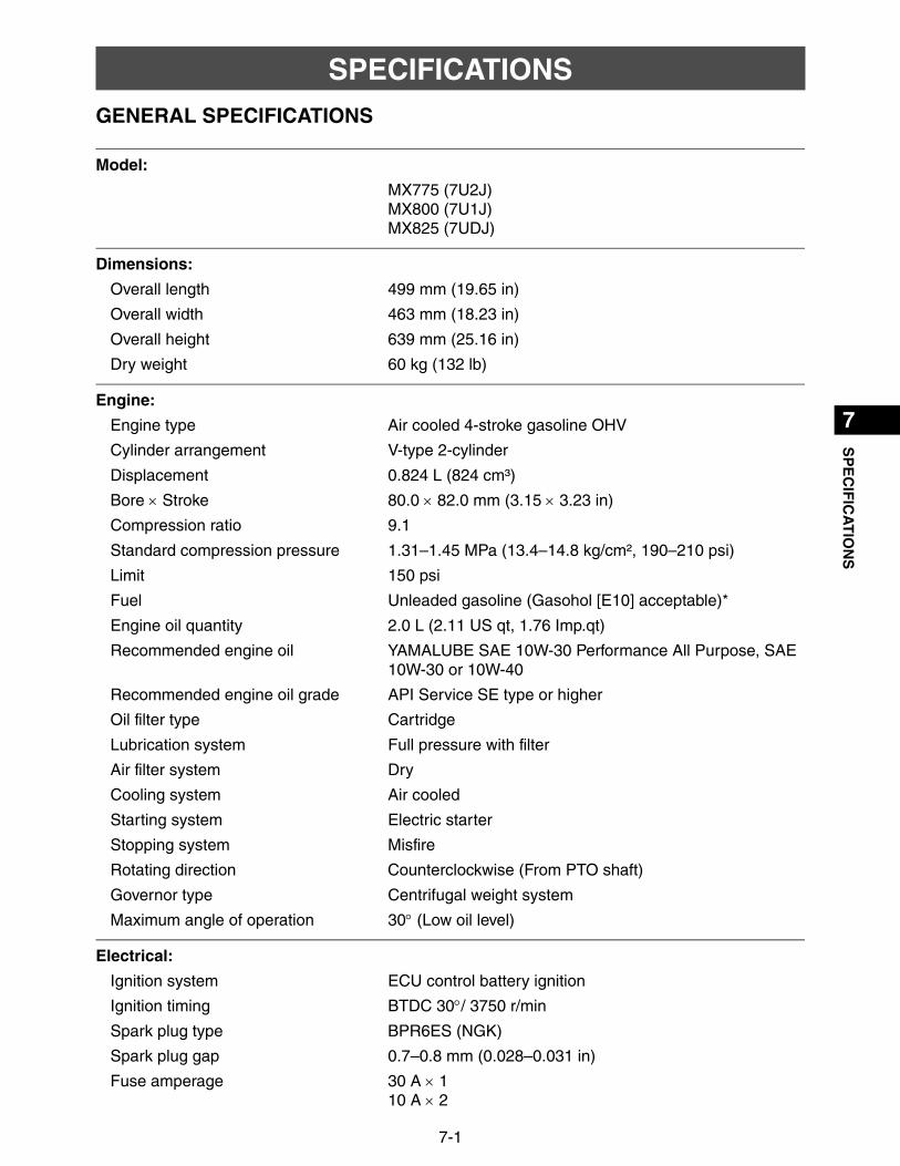
1
2
3
4
5
6
7
8
9
10
SP
EC
IFIC
AT
ION
S
7-1
SPECIFICATIONSGENERAL SPECIFICATIONS
Model:
MX775 (7U2J)MX800 (7U1J)MX825 (7UDJ)
Dimensions:
Overall length 499 mm (19.65 in)
Overall width 463 mm (18.23 in)
Overall height 639 mm (25.16 in)
Dry weight 60 kg (132 lb)
Engine:
Engine type Air cooled 4-stroke gasoline OHV
Cylinder arrangement V-type 2-cylinder
Displacement 0.824 L (824 cm³)
Bore Stroke 80.0 82.0 mm (3.15 3.23 in)
Compression ratio 9.1
Standard compression pressure 1.31–1.45 MPa (13.4–14.8 kg/cm², 190–210 psi)
Limit 150 psi
Fuel Unleaded gasoline (Gasohol [E10] acceptable)*
Engine oil quantity 2.0 L (2.11 US qt, 1.76 Imp.qt)
Recommended engine oil YAMALUBE SAE 10W-30 Performance All Purpose, SAE 10W-30 or 10W-40
Recommended engine oil grade API Service SE type or higher
Oil filter type Cartridge
Lubrication system Full pressure with filter
Air filter system Dry
Cooling system Air cooled
Starting system Electric starter
Stopping system Misfire
Rotating direction Counterclockwise (From PTO shaft)
Governor type Centrifugal weight system
Maximum angle of operation 30 (Low oil level)
Electrical:
Ignition system ECU control battery ignition
Ignition timing BTDC 30/ 3750 r/min
Spark plug type BPR6ES (NGK)
Spark plug gap 0.7–0.8 mm (0.028–0.031 in)
Fuse amperage 30 A 110 A 2

7-2
1
2
3
4
5
6
7
8
9
10SP
EC
IFIC
AT
ION
SGENERAL SPECIFICATIONS
****** Yamaha engine has been designed to use regular unleaded gasoline with a pump octane number((R+M)/2) of 86 or higher, or research octane number of 91 or higher.Gasohol containing ethanol can be used if the ethanol content does not exceed 10 % (E10).
Use only unleaded gasoline. The use of leaded gasoline will cause severe damage to internalengine parts.
NOTICE
7-3
1
2
3
4
5
6
7
8
9
10
SP
EC
IFIC
AT
ION
SMAINTENANCE SPECIFICATIONS
MAINTENANCE SPECIFICATIONS
ENGINE
Piston:
Piston-to-cylinder clearance 0.033–0.047 mm (0.0013–0.0019 in)
Limit 0.15 mm (0.0059 in)
Piston diameter 79.959–79.980 mm (3.1480–3.1488 in)
Limit 79.900 mm (3.1457 in)
Measuring point (from piston skirt bottom)
6.0 mm (0.2362 in)
Oversize 1st 80.25 mm (3.1594 in)
2nd 80.50 mm (3.1693 in)
Piston pin hole inside diameter 19.004–19.015 mm (0.7482–0.7486 in)
Limit 19.045 mm (0.7498 in)
Piston pin:
Piston pin diameter 18.995–19.000 mm (0.7478–0.7480 in)
Limit 18.975 mm (0.7470 in)
Piston ring:
Top ringType BarrelDimensions 1.2 2.9 mm (0.0472 0.1142 in)End gap (installed) 0.20–0.35 mm (0.0079–0.0138 in)Limit 0.60 mm (0.0236 in)Side clearance 0.04–0.08 mm (0.0016–0.0031 in)Limit 0.13 mm (0.0051 in)
2nd ringType TaperDimensions 1.0 2.5 mm (0.0394 0.0984 in)End gap (installed) 0.20–0.35 mm (0.0079–0.0138 in)Limit 0.60 mm (0.0236 in)Side clearance 0.03–0.07 mm (0.0012–0.0028 in)Limit 0.13 mm (0.0051 in)
Oil ringType 3-piece typeDimensions 2.0 2.5 mm (0.0787 0.0984 in)End gap (installed) 0.20–0.70 mm (0.0079–0.0276 in)
Cylinder head:
Warpage limit 0.05 mm (0.002 in)
Cylinder:
Bore 80.000–80.020 mm (3.1496–3.1504 in)
Warpage limit 80.025 mm (3.1506 in)
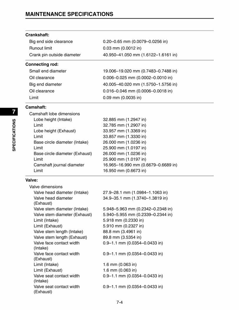
7-4
1
2
3
4
5
6
7
8
9
10SP
EC
IFIC
AT
ION
SMAINTENANCE SPECIFICATIONS
Crankshaft:
Big end side clearance 0.20–0.65 mm (0.0079–0.0256 in)
Runout limit 0.03 mm (0.0012 in)
Crank pin outside diameter 40.950–41.050 mm (1.6122–1.6161 in)
Connecting rod:
Small end diameter 19.006–19.020 mm (0.7483–0.7488 in)
Oil clearance 0.006–0.025 mm (0.0002–0.0010 in)
Big end diameter 40.005–40.020 mm (1.5750–1.5756 in)
Oil clearance 0.016–0.046 mm (0.0006–0.0018 in)
Limit 0.09 mm (0.0035 in)
Camshaft:
Camshaft lobe dimensionsLobe height (Intake) 32.885 mm (1.2947 in)Limit 32.785 mm (1.2907 in)Lobe height (Exhaust) 33.957 mm (1.3369 in)Limit 33.857 mm (1.3330 in)Base circle diameter (Intake) 26.000 mm (1.0236 in)Limit 25.900 mm (1.0197 in)Base circle diameter (Exhaust) 26.000 mm (1.0236 in)Limit 25.900 mm (1.0197 in)Camshaft journal diameter 16.965–16.990 mm (0.6679–0.6689 in)Limit 16.950 mm (0.6673 in)
Valve:
Valve dimensionsValve head diameter (Intake) 27.9–28.1 mm (1.0984–1.1063 in)Valve head diameter (Exhaust)
34.9–35.1 mm (1.3740–1.3819 in)
Valve stem diameter (Intake) 5.948–5.963 mm (0.2342–0.2348 in)Valve stem diameter (Exhaust) 5.940–5.955 mm (0.2339–0.2344 in)Limit (Intake) 5.918 mm (0.2330 in)Limit (Exhaust) 5.910 mm (0.2327 in)Valve stem length (Intake) 88.8 mm (3.4961 in)Valve stem length (Exhaust) 89.8 mm (3.5354 in)Valve face contact width (Intake)
0.9–1.1 mm (0.0354–0.0433 in)
Valve face contact width (Exhaust)
0.9–1.1 mm (0.0354–0.0433 in)
Limit (Intake) 1.6 mm (0.063 in)Limit (Exhaust) 1.6 mm (0.063 in)Valve seat contact width (Intake)
0.9–1.1 mm (0.0354–0.0433 in)
Valve seat contact width (Exhaust)
0.9–1.1 mm (0.0354–0.0433 in)

7-5
1
2
3
4
5
6
7
8
9
10
SP
EC
IFIC
AT
ION
SMAINTENANCE SPECIFICATIONS
Limit (Intake) 1.6 mm (0.063 in)Limit (Exhaust) 1.6 mm (0.063 in)Valve stem runout limit 0.01 mm (0.0004 in)
Valve guide
Guide inside diameter (Intake) 6.000–6.012 mm (0.2362–0.2367 in)
Guide inside diameter (Exhaust) 6.000–6.012 mm (0.2362–0.2367 in)
Stem to guide clearance (Intake) 0.08 mm (0.0031 in)
Stem to guide clearance (Exhaust)
0.10 mm (0.0039 in)
Valve clearance (cold)Intake 0.02–0.2 mm (0.0008–0.01 in)Exhaust 0.02–0.2 mm (0.0008–0.01 in)
Push rod:
Runout limit 0.3 mm (0.0118 in)
Rocker arm:
Rocker arm shaft hole inside diameter (Intake)
12.000–12.018 mm (0.4724–0.4731 in)
Rocker arm shaft hole inside diameter (Exhaust)
12.000–12.018 mm (0.4724–0.4731 in)
Rocker arm shaft diameter (Intake)
11.981–11.991 mm (0.4717–0.4721 in)
Rocker arm shaft diameter (Exhaust)
11.981–11.991 mm (0.4717–0.4721 in)
Oil clearance 0.08 mm (0.0031 in)
Valve spring:
Valve spring free length (Intake) 37.1 mm (1.4606 in)
Valve spring free length (Exhaust)
35.6 mm (1.4016 in)
Limit (Intake) 35.25 mm (1.3878 in)
Limit (Exhaust) 33.82 mm (1.3315 in)
Installed length (Intake) 29.3 mm (1.1535 in)
Installed length (Exhaust) 29.0 mm (1.1417 in)
Installed compression spring force (Intake)
67.7 N (6.90 kgf, 15.2 lbf)
Installed compression spring force (Exhaust)
118.1 N (12.0 kgf, 26.5 lbf)
Tilt limit 2.0 mm (0.0787 in)
Fuel pump:
Pump type (Lo) Mechanical
Pump type (Hi) Electrical

7-6
1
2
3
4
5
6
7
8
9
10SP
EC
IFIC
AT
ION
SMAINTENANCE SPECIFICATIONS
Fuel line pressure (at idle) 255–285 kPa (2.55–2.85 kgf/cm², 36.98–41.33 psi)
Fuel injector:
Resistance 11.4–12.6
Oil pump:
Inner-rotor-to-outer-rotor-tip clearance
0.19–0.35 mm (0.008–0.013 in)
Relief valve operating pressure 342–538 kPa (3.42–5.38 kgf/cm², 49.59–78.01 psi)
Throttle body:
ID mark E-3750-2 (MX775)E-3750-1 (MX800)E-3750-0 (MX825)
Throttle position sensor:
Output voltage (at idle) 0.95–4.5 V
Resistance 3.0–7.0 k
Governor assembly:
Tension spring attach hole 7
Engine speed:
High engine speed (with no load) 3550–3600 r/min
Low engine speed (with no load) 1450–1550 r/min
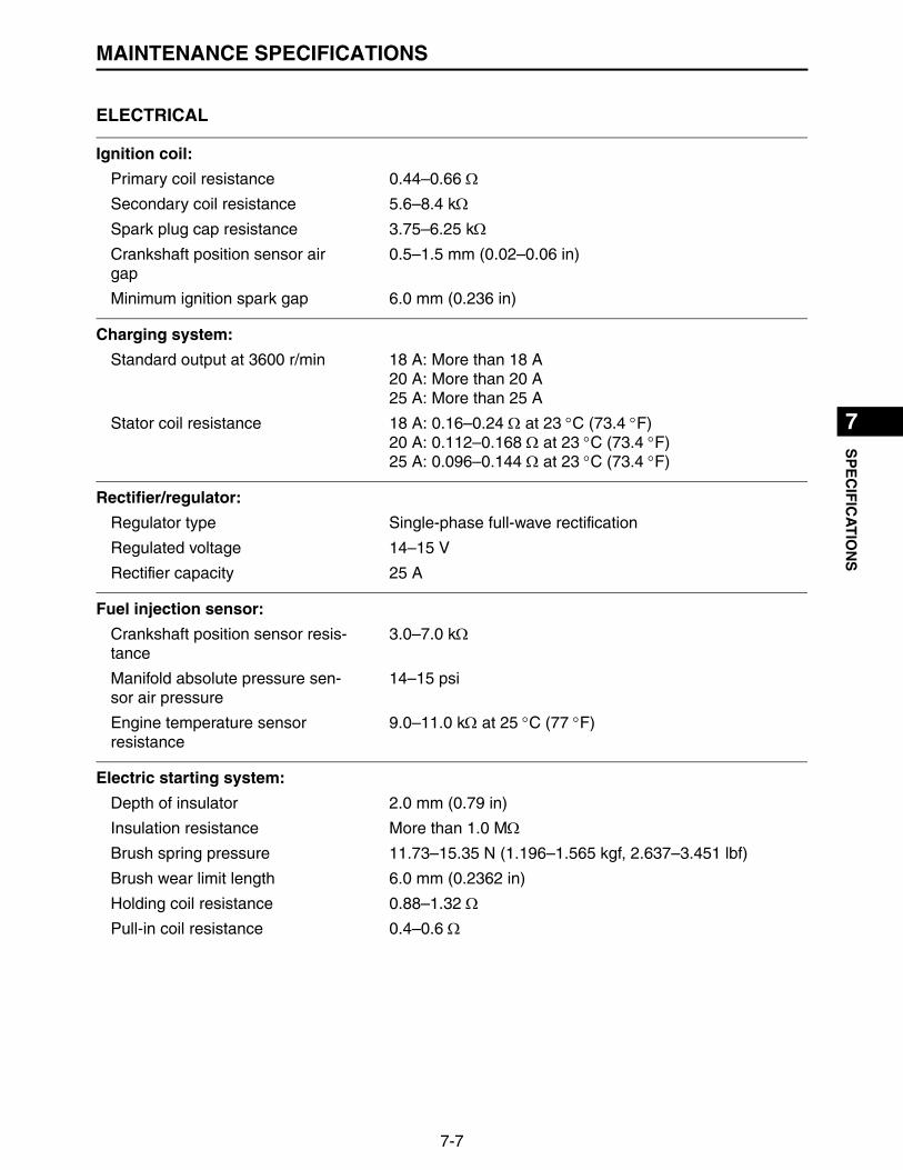
7-7
1
2
3
4
5
6
7
8
9
10
SP
EC
IFIC
AT
ION
SMAINTENANCE SPECIFICATIONS
ELECTRICAL
Ignition coil:
Primary coil resistance 0.44–0.66
Secondary coil resistance 5.6–8.4 k
Spark plug cap resistance 3.75–6.25 k
Crankshaft position sensor air gap
0.5–1.5 mm (0.02–0.06 in)
Minimum ignition spark gap 6.0 mm (0.236 in)
Charging system:
Standard output at 3600 r/min 18 A: More than 18 A20 A: More than 20 A25 A: More than 25 A
Stator coil resistance 18 A: 0.16–0.24 at 23 C (73.4 F)20 A: 0.112–0.168 at 23 C (73.4 F)25 A: 0.096–0.144 at 23 C (73.4 F)
Rectifier/regulator:
Regulator type Single-phase full-wave rectification
Regulated voltage 14–15 V
Rectifier capacity 25 A
Fuel injection sensor:
Crankshaft position sensor resis-tance
3.0–7.0 k
Manifold absolute pressure sen-sor air pressure
14–15 psi
Engine temperature sensor resistance
9.0–11.0 k at 25 C (77 F)
Electric starting system:
Depth of insulator 2.0 mm (0.79 in)
Insulation resistance More than 1.0 M
Brush spring pressure 11.73–15.35 N (1.196–1.565 kgf, 2.637–3.451 lbf)
Brush wear limit length 6.0 mm (0.2362 in)
Holding coil resistance 0.88–1.32
Pull-in coil resistance 0.4–0.6
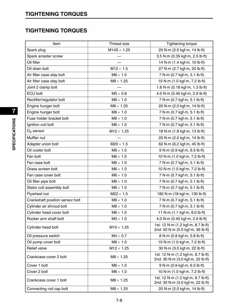
7-8
1
2
3
4
5
6
7
8
9
10SP
EC
IFIC
AT
ION
STIGHTENING TORQUES
TIGHTENING TORQUES
Item Thread size Tightening torque
Spark plug M14S 1.25 20 N·m (2.0 kgf·m, 14 lb·ft)
Spark arrester screw — 3.5 N·m (0.35 kgf·m, 2.5 lb·ft)
Oil filter — 14 N·m (1.4 kgf·m, 10 lb·ft)
Oil drain bolt M12 1.5 27 N·m (2.7 kgf·m, 20 lb·ft)
Air filter case stay bolt M6 1.0 7 N·m (0.7 kgf·m, 5.1 lb·ft)
Air filter case stay bolt M8 1.25 10 N·m (1.0 kgf·m, 7.2 lb·ft)
Joint 2 clamp bolt — 1.8 N·m (0.18 kgf·m, 1.3 lb·ft)
ECU bolt M5 0.8 4.0 N·m (0.40 kgf·m, 2.9 lb·ft)
Rectifier/regulator bolt M6 1.0 7 N·m (0.7 kgf·m, 5.1 lb·ft)
Engine hunger bolt M8 1.25 20 N·m (2.0 kgf·m, 14 lb·ft)
Engine hunger bolt M6 1.0 7 N·m (0.7 kgf·m, 5.1 lb·ft)
Fuse holder bracket bolt M6 1.0 7 N·m (0.7 kgf·m, 5.1 lb·ft)
Ignition coil bolt M6 1.0 7 N·m (0.7 kgf·m, 5.1 lb·ft)
O2 sensor M12 1.25 18 N·m (1.8 kgf·m, 13 lb·ft)
Muffler nut — 20 N·m (2.0 kgf·m, 14 lb·ft)
Adapter union bolt M20 1.5 62 N·m (6.2 kgf·m, 45 lb·ft)
Oil cooler bolt M6 1.0 9 N·m (0.9 kgf·m, 6.5 lb·ft)
Fan bolt M6 1.0 10 N·m (1.0 kgf·m, 7.2 lb·ft)
Fan case bolt M6 1.0 7 N·m (0.7 kgf·m, 5.1 lb·ft)
Grass screen bolt M6 1.0 10 N·m (1.0 kgf·m, 7.2 lb·ft)
Fan case cover bolt M6 1.0 7 N·m (0.7 kgf·m, 5.1 lb·ft)
Oil filler pipe bolt M6 1.0 7 N·m (0.7 kgf·m, 5.1 lb·ft)
Stator coil assembly bolt M6 1.0 7 N·m (0.7 kgf·m, 5.1 lb·ft)
Flywheel nut M22 1.5 180 N·m (18 kgf·m, 130 lb·ft)
Crankshaft position sensor bolt M6 1.0 7 N·m (0.7 kgf·m, 5.1 lb·ft)
Cylinder air shroud bolt M6 1.0 7 N·m (0.7 kgf·m, 5.1 lb·ft)
Cylinder head cover bolt M6 1.0 11 N·m (1.1 kgf·m, 8.0 lb·ft)
Rocker arm shaft bolt M5 1.0 4.0 N·m (0.40 kgf·m, 2.9 lb·ft)
Cylinder head bolt M10 1.251st: 12 N·m (1.2 kgf·m, 8.7 lb·ft)2nd: 50 N·m (5.0 kgf·m, 36 lb·ft)
Oil pressure switch M4 0.7 8 N·m (0.8 kgf·m, 5.8 lb·ft)
Oil pump cover bolt M6 1.0 10 N·m (1.0 kgf·m, 7.2 lb·ft)
Relief valve M12 1.25 30 N·m (3.0 kgf·m, 22 lb·ft)
Crankcase cover 2 bolt M8 1.251st: 12 N·m (1.2 kgf·m, 8.7 lb·ft)2nd: 30 N·m (3.0 kgf·m, 22 lb·ft)
Cover 1 bolt M6 1.0 9 N·m (0.9 kgf·m, 6.5 lb·ft)
Cover 2 bolt M6 1.0 10 N·m (1.0 kgf·m, 7.2 lb·ft)
Crankcase cover 1 bolt M8 1.251st: 12 N·m (1.2 kgf·m, 8.7 lb·ft)2nd: 30 N·m (3.0 kgf·m, 22 lb·ft)
Connecting rod cap bolt M8 1.25 20 N·m (2.0 kgf·m, 14 lb·ft)

7-9
1
2
3
4
5
6
7
8
9
10
SP
EC
IFIC
AT
ION
STIGHTENING TORQUES
Engine temperature sensor M10 1.5 12 N·m (1.2 kgf·m, 8.7 lb·ft)
Reed valve M6 1.0 10 N·m (1.0 kgf·m, 7.2 lb·ft)
Scroll air shroud bolt M6 1.0 7 N·m (0.7 kgf·m, 5.1 lb·ft)
Low-pressure fuel pump bolt M6 1.0 7 N·m (0.7 kgf·m, 5.1 lb·ft)
High-pressure fuel pump bolt M6 1.0 9 N·m (0.9 kgf·m, 6.5 lb·ft)
Fuel pump bracket M6 1.0 9 N·m (0.9 kgf·m, 6.5 lb·ft)
Throttle body assembly nut M6 1.0 7 N·m (0.7 kgf·m, 5.1 lb·ft)
Governor assembly bolt M6 1.0 8 N·m (0.8 kgf·m, 5.8 lb·ft)
Inlet pipe bolt M6 1.0 9 N·m (0.9 kgf·m, 6.5 lb·ft)
Manifold absolute pressure sensor bolt
M6 1.0 7 N·m (0.7 kgf·m, 5.1 lb·ft)
Intake manifold nut and bolt M6 1.01st: 3.0 N·m (0.30 kgf·m, 2.2 lb·ft)2nd: 7 N·m (0.7 kgf·m, 5.1 lb·ft)
Starter motor assembly bolt M8 1.25 23 N·m (2.3 kgf·m, 17 lb·ft)
Earth terminal nut M8 1.25 9 N·m (0.9 kgf·m, 6.5 lb·ft)
Starter motor rear bracket bolt M6 0.8 6 N·m (0.6 kgf·m, 4.3 lb·ft)
Starter relay nut M6 1.0 11 N·m (1.1 kgf·m, 8.0 lb·ft)
Item Thread size Tightening torque

7-10
1
2
3
4
5
6
7
8
9
10SP
EC
IFIC
AT
ION
SGENERAL TORQUE SPECIFICATIONS
GENERAL TORQUE SPECIFICATIONS
This chart specifies torque for standard fasteners with standard I.S.O. pitch threads. Torque specifi-cations for special components or assemblies are included in the applicable sections of this book. Toavoid warpage, tighten multi fastener assemblies in a crisscross fashion, in progressive stages, untilfull torque is reached. Unless otherwise specifications call for clean, dry threads. Componentsshould be at room temperature.
Thread sizeTightening torque
N·m kgf·m lb·ft
M4 2 0.2 1.5
M5 3 0.3 2.2
M6 7 0.7 5.2
M7 10 1.0 7.4
M8 15 1.5 11.1
M10 30 3.0 22.1
M12 60 6.0 44.3
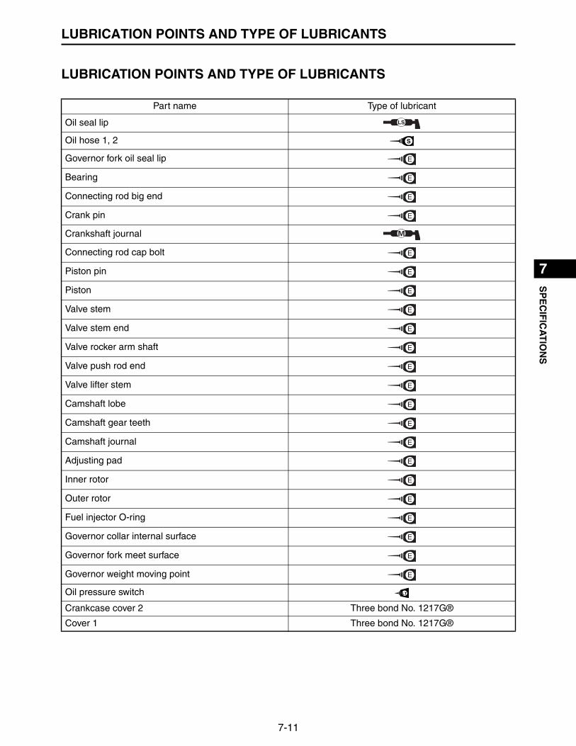
7-11
1
2
3
4
5
6
7
8
9
10
SP
EC
IFIC
AT
ION
SLUBRICATION POINTS AND TYPE OF LUBRICANTS
LUBRICATION POINTS AND TYPE OF LUBRICANTS
Part name Type of lubricant
Oil seal lip
Oil hose 1, 2
Governor fork oil seal lip
Bearing
Connecting rod big end
Crank pin
Crankshaft journal
Connecting rod cap bolt
Piston pin
Piston
Valve stem
Valve stem end
Valve rocker arm shaft
Valve push rod end
Valve lifter stem
Camshaft lobe
Camshaft gear teeth
Camshaft journal
Adjusting pad
Inner rotor
Outer rotor
Fuel injector O-ring
Governor collar internal surface
Governor fork meet surface
Governor weight moving point
Oil pressure switch
Crankcase cover 2 Three bond No. 1217G®
Cover 1 Three bond No. 1217G®
LS
S
E
E
E
E
E
E
E
E
E
E
E
E
E
E
E
E
E
E
E
E
E
E
LT
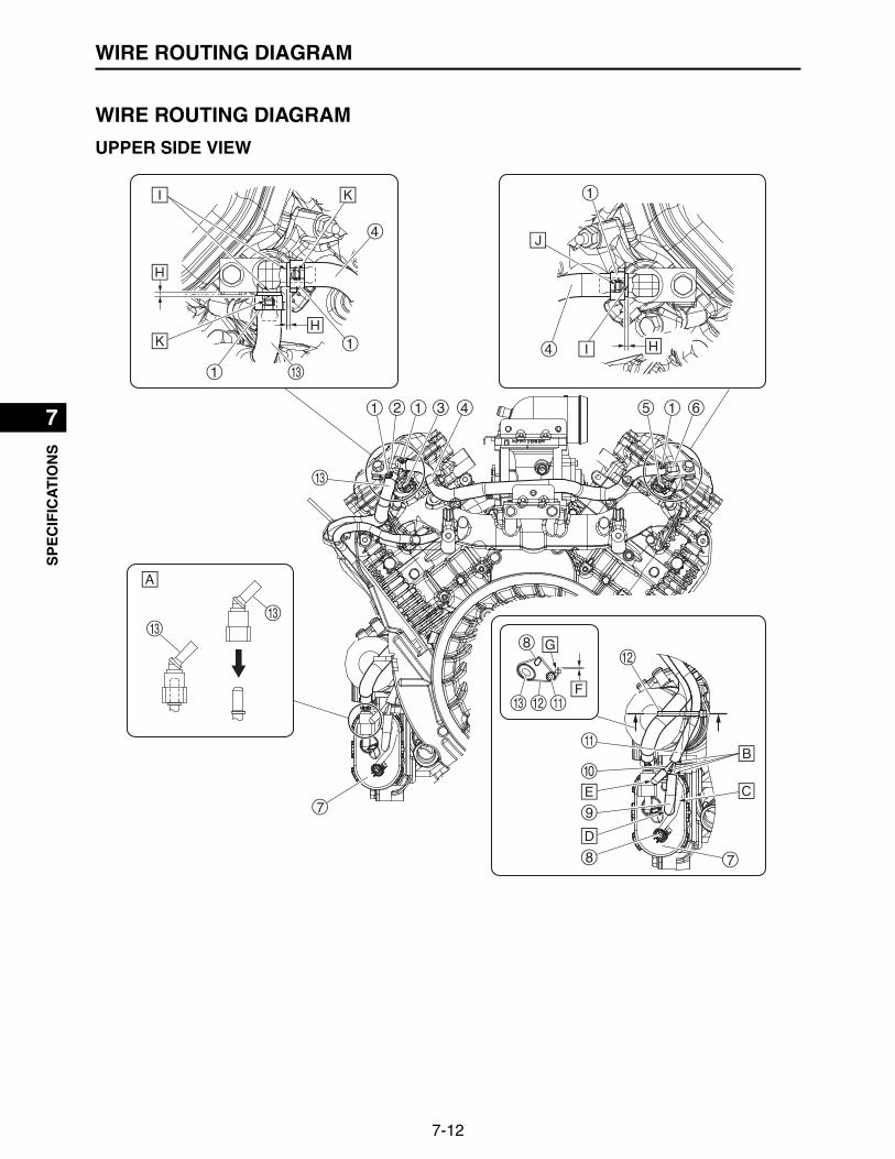
7-12
1
2
3
4
5
6
7
8
9
10SP
EC
IFIC
AT
ION
SWIRE ROUTING DIAGRAM
WIRE ROUTING DIAGRAM
UPPER SIDE VIEW

7-13
1
2
3
4
5
6
7
8
9
10
SP
EC
IFIC
AT
ION
SWIRE ROUTING DIAGRAM
1. Hose clamp 8. Wire harness2. Inlet pipe 2 9. Purge hose 23. Fuel injector #2 10.3 WAY joint4. Fuel injector pipe 2 11.Purge hose 15. Fuel injector #1 12.Plastic locking tie6. Inlet pipe 1 13.Fuel injector pipe 17. High-pressure fuel pump
A. Fuel injector pipe 1 connector installation details• Insert the fuel injector pipe 1 connector until a click is heard, and then make sure that the connector is
not disconnected.• When inserting the fuel injector pipe 1 connector, pay attention not to prize.
B. Insert the purge hose 1, purge hose 2, cap all the way into the 3 WAY joint.C. Make sure that there is no looseness or tension of the lead.D. Insert the protector side of the purge hose 2 all the way into the pipe of the fuel pump.E. Install the cap in the direction shown in the illustration.F. Keep the length shown in the illustration to 0–2.0 mm (0–0.08 in) and cut off the end of the plastic lock-
ing tie.G. The binding area of the plastic locking tie should be on the outside of the engine.H. 2.0–4.0 mm (0.08–0.16 in)I. Insert the fuel injector pipes until it contacts the inlet pipes.J. Install the yellow painted portion in the direction shown in the illustration.K. Install the white painted portion in the direction shown in the illustration.

7-14
1
2
3
4
5
6
7
8
9
10SP
EC
IFIC
AT
ION
SWIRE ROUTING DIAGRAM

7-15
1
2
3
4
5
6
7
8
9
10
SP
EC
IFIC
AT
ION
SWIRE ROUTING DIAGRAM
1. Crankshaft position sensor 12.Fuel injector #2 coupler2. Ignition coil #2 13.Manifold absolute pressure sensor lead3. Throttle position sensor lead 14.Ignition coil #2 coupler4. Engine temperature sensor lead 15.Fuel injector #1 lead5. O2 sensor lead 16.Ignition coil #1 lead6. Ignition coil #1 coupler 17.Plastic locking tie7. Fuel injector #1 coupler 18.Fuel injector #2 and crankshaft position sensor
lead8. Ignition coil #1 19.High-pressure fuel pump lead and oil pressure
switch lead9. Wire harness 20.Ignition coil #2 lead10.Stator 21.Fuel injector #2 lead11.Crankshaft position sensor coupler 22.Intake manifold
A. Install the leads so that they overlap each other.B. Lock the fuel injector coupler after installation.C. Install the lead as shown in the illustration.D. Gap between crankshaft position sensor and rotor should be 0.5–1.5 mm (0.02–0.06 in).E. Installation details of ignition coil and couplerF. After installing the coupler, insert it until it is locked.G. BossH. Align the wire harness with the boss of the intake manifold.I. BranchJ. Position the plastic locking tie between the projections as shown in the illustration.K. ProjectionL. Allowance 2.0 mm (0.08 in) or lessM. Direction of upper surface of the engineN. Install the lock of the plastic locking tie as shown in the illustration.
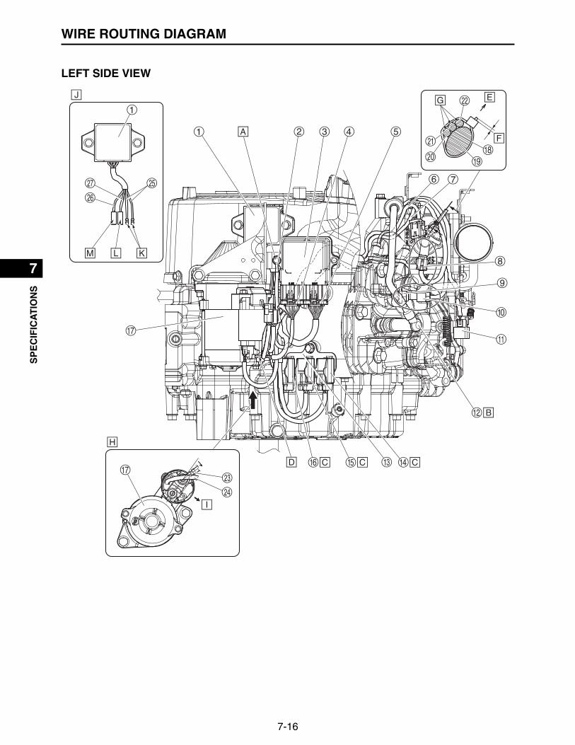
7-16
1
2
3
4
5
6
7
8
9
10SP
EC
IFIC
AT
ION
SWIRE ROUTING DIAGRAM
LEFT SIDE VIEW

7-17
1
2
3
4
5
6
7
8
9
10
SP
EC
IFIC
AT
ION
SWIRE ROUTING DIAGRAM
1. Rectifier/regulator 15.Fuse (10 A) coupler2. Earth terminal 16.Fuse (30 A) coupler3. ECU 17.Starter motor4. ECU coupler (black) 18.Plastic locking tie5. ECU coupler (gray) 19.Throttle body6. Fuel injector #1 lead 20.Throttle position sensor lead7. Ignition coil #1 lead 21.Engine temperature sensor lead8. Throttle position sensor coupler 22.O2 sensor lead9. Engine temperature sensor 23.Starter motor lead10.Engine temperature sensor coupler 24.Starter relay lead11.O2 sensor coupler 25.Rectifier/regulator lead (white)12.Spark plug cap 26.Rectifier/regulator lead (red)13.Stay 27.Rectifier/regulator lead (black)14.Fuse (10 A) coupler
A. Tighten the earth terminal together with the mounting bolt in the direction shown in the illustration.B. Install the spark plug cap in the direction shown in the illustration.C. Install in the stay.D. Tighten together with the vehicle battery positive terminal.E. Direction of upper surface of the engineF. Allowance 2.0 mm (0.08 in) or lessG. Install the leads so that they do not overlap each other.H. Starter motor lead installation detailsI. Engine sideJ. Rectifier/regulator lead installation detailsK. Connect with the stator lead connector (female). (Polarity does not matter)L. Connect with the wire harness connector (male/black).M. Connect with the wire harness connector (male/red).

7-18
1
2
3
4
5
6
7
8
9
10SP
EC
IFIC
AT
ION
SWIRE ROUTING DIAGRAM
RIGHT SIDE VIEW
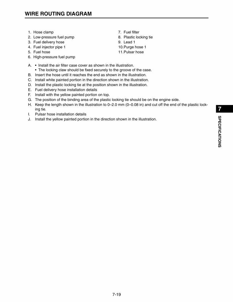
7-19
1
2
3
4
5
6
7
8
9
10
SP
EC
IFIC
AT
ION
SWIRE ROUTING DIAGRAM
1. Hose clamp 7. Fuel filter2. Low-pressure fuel pump 8. Plastic locking tie3. Fuel delivery hose 9. Lead 14. Fuel injector pipe 1 10.Purge hose 15. Fuel hose 11.Pulsar hose6. High-pressure fuel pump
A. • Install the air filter case cover as shown in the illustration.• The locking claw should be fixed securely to the groove of the case.
B. Insert the hose until it reaches the end as shown in the illustration.C. Install white painted portion in the direction shown in the illustration.D. Install the plastic locking tie at the position shown in the illustration.E. Fuel delivery hose installation detailsF. Install with the yellow painted portion on top.G. The position of the binding area of the plastic locking tie should be on the engine side.H. Keep the length shown in the illustration to 0–2.0 mm (0–0.08 in) and cut off the end of the plastic lock-
ing tie.I. Pulsar hose installation detailsJ. Install the yellow painted portion in the direction shown in the illustration.

7-20
1
2
3
4
5
6
7
8
9
10SP
EC
IFIC
AT
ION
SWIRE ROUTING DIAGRAM
1. Oil hose 1 4. Oil hose 22. Oil cooler 5. Oil filter3. Hose clamp
A. Insert the oil hose all the way into the oil cooler.B. Face the projection inward.C. Install the white painted portion in the direction shown in the illustration.D. 8–12 mm (0.31–0.47 in)E. Install the hose clamp in the direction shown in the illustration.F. Install the yellow painted portion in the direction shown in the illustration.G. 2.0–4.0 mm (0.08–0.16 in)H. Face the projection outward.

7-21
1
2
3
4
5
6
7
8
9
10
SP
EC
IFIC
AT
ION
SWIRE ROUTING DIAGRAM
1. Fuel injector #2 lead 5. High-pressure fuel pump coupler2. Ignition coil #2 lead 6. Oil pressure switch3. High-pressure fuel pump lead 7. Oil pressure switch lead4. Purge hose 8. Spark plug cap
A. The high-pressure fuel pump coupler should be laid along the purge hose.B. Install the spark plug cap in the direction shown in the illustration.C. Oil pressure switch lead routing directionD. Direction of upper surface of the engine
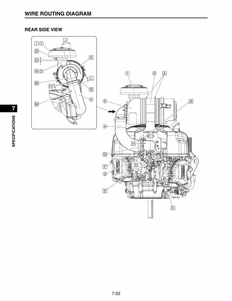
7-22
1
2
3
4
5
6
7
8
9
10SP
EC
IFIC
AT
ION
SWIRE ROUTING DIAGRAM
REAR SIDE VIEW

7-23
1
2
3
4
5
6
7
8
9
10
SP
EC
IFIC
AT
ION
SWIRE ROUTING DIAGRAM
1. Air filter cover 1 4. Joint 22. Air filter case stay 5. Air filter case3. Breather hose
A. Install the air filter case stay into the groove in the air filter case.B. Install the screw in the direction shown in the illustration.C. Insert the protector side of the purge hose 1 all the way into the pipe of the throttle body.D. 19–21 mm (0.75–0.83 in)E. Install the white painted portion in the direction shown in the illustration.F. Insert the breather hose all the way into the pipe of the joint 1.G. Insert the joint 2 until it contacts the projection on the joint 1.H. 2.0–4.0 mm (0.08–0.16 in)I. Insert the air filter cover 1 until it contacts the air filter case.J. Installation angle of joint 2 15.75 (reference value)K. Install the joint 2 in the direction shown in the illustration.L. Insert from 22 mm (0.87 in) until contact is made as shown in the illustration.M. The air filter case and joint 2 should not be bent or detached due to unreasonable installation.N. Install the air filter case in the direction shown in the illustration.O. 5–7 mm (0.20–0.28 in)

7-24
1
2
3
4
5
6
7
8
9
10SP
EC
IFIC
AT
ION
SWIRE ROUTING DIAGRAM
1. Manifold absolute pressure sensor coupler 5. Plastic locking tie2. Manifold absolute pressure sensor 6. Inlet manifold3. Clamp 7. Ignition coil #1 lead4. O2 sensor coupler 8. Fuel injector #1 lead
A. FI diagnostic tool couplerB. Main switch couplerC. Direction of upper surface of the engineD. Allowance 2.0 mm (0.08 in) or lessE. Install the plastic locking tie as shown in the illustration.F. • Install the leads so that they do not overlap each other.
• The leads should not interfere with the side of the fan case.

7-25
1
2
3
4
5
6
7
8
9
10
SP
EC
IFIC
AT
ION
SWIRE ROUTING DIAGRAM
MEMO

APPENDIXCIRCUIT DIAGRAM
W/R
Y
V
Br
250Ω
LED
(B) (Gy)
R/LW
GBr/GL
GY
BG
BrBV
RW/B
B
L
Y
B/WB
L/W
P/L
W/B
W
G/W
L/WGBrP/LBG
/Y
OG/R
Gy
RBGy
R/L
B
G/RB
O
R
B/WB
G
R
GyBG/YBr
G/W
R/W
R/WB
B
R
BRWW
Y
L/O
Y/L
L/O
R
R
Y/L
R/Y
R/Y
R/Y
R/Y
R/Y
R/Y
R/Y
R/Y
R/Y
30A10A
10A
OF
F
ON
START2
3
1
7
89
0
w
w
e
r
y
u
o
a
t
f
g
p
s
d
i
4
5
6
q
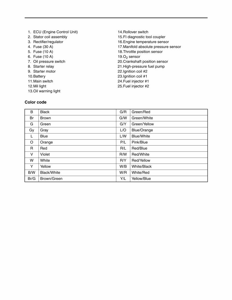
Color code
1. ECU (Engine Control Unit) 14.Rollover switch2. Stator coil assembly 15.FI diagnostic tool coupler3. Rectifier/regulator 16.Engine temperature sensor4. Fuse (30 A) 17.Manifold absolute pressure sensor5. Fuse (10 A) 18.Throttle position sensor6. Fuse (10 A) 19.O2 sensor7. Oil pressure switch 20.Crankshaft position sensor8. Starter relay 21.High-pressure fuel pump9. Starter motor 22.Ignition coil #210.Battery 23.Ignition coil #111.Main switch 24.Fuel injector #112.Mil light 25.Fuel injector #213.Oil warning light
B Black G/R Green/Red
Br Brown G/W Green/White
G Green G/Y Green/Yellow
Gy Gray L/O Blue/Orange
L Blue L/W Blue/White
O Orange P/L Pink/Blue
R Red R/L Red/Blue
V Violet R/W Red/White
W White R/Y Red/Yellow
Y Yellow W/B White/Black
B/W Black/White W/R White/Red
Br/G Brown/Green Y/L Yellow/Blue

MEMO

7UD-F8197-E0_Cover.indd 2 2016/12/13 11:23:58

SERVICE MANUAL
MX775MX800MX825
7UD-F8197-E0LIT-19616-02-372016.12×1 !
7UD-F8197-E0_Cover.indd 1 2016/12/13 11:23:58
Related Documents