Overview The MWS5 series of miniature microwave presence detectors provide automatic control of lighting loads with optional manual control. As microwave radiation penetrates plastic and glass, this unit has been specifically designed to be mounted inside a luminaire. Three models are available: premium, direct dim, and analogue dim all of which will switch incandescent, fluorescent and compact fluorescent lighting. The direct dim variant controls DALI or DSI digital dimming ballasts whilst the analogue dim variant controls 1-10V dimming ballasts. The unit detects movement using a microwave sensor and turns the load on. When an area is no longer occupied the load will switch off after an adjustable time out period. A selection of fixing clips to allow the unit to me mounted in or to the side of a luminaire are available. All functionality is fully programmable using an IR handset. Features Miniature Microwave Presence Detector (luminaire fitting) MWS5 (standard & slim-line PSU) Product Guide Standard power supply Microwave Sensor Detects movement within the unit’s detection range, allowing load control in response to changes in occupancy. IR Receiver Receives control and programming commands from an IR (infrared) handset. Light Level Sensor Measures the overall light level in the detection area Status LEDs The LED flashes Red to indicate the following: RJ11 connector The sensor head has a flying lead with a RJ11 plug at the end plugs into the RJ11 socket on the power supply. Standard power supply This power supply has a 6A relay. It also has connections for an external switch that can be used to turn on the load when absence detection mode has been set or raised / lowered with dimming variants. Slim-line power supply Where space is at a premium the slim-line power supply is compact and suitable for luminaire mounting where a 2A relay is sufficient. This power supply does not have connections for external switches. Walk Test LED active when movement is detected Valid setting received Sensor head Lens which covers... IR Receiver Light Level Sensor Status LED Slim-line power supply Dimming version shown Dimming version shown

Welcome message from author
This document is posted to help you gain knowledge. Please leave a comment to let me know what you think about it! Share it to your friends and learn new things together.
Transcript
Overview
The MWS5 series of miniature microwave presence detectors provide automatic control of lighting loads with optional manual control. As microwave radiation penetrates plastic and glass, this unit has been specifically designed to be mounted inside a luminaire.
Three models are available: premium, direct dim, and analogue dim all of which will switch incandescent, fluorescent and compact fluorescent lighting. The direct dim variant controls DALI or DSI digital dimming ballasts whilst the analogue dim variant controls 1-10V dimming ballasts.
The unit detects movement using a microwave sensor and turns the load on. When an area is no longer occupied the load will switch off after an adjustable time out period.
A selection of fixing clips to allow the unit to me mounted in or to the side of a luminaire are available.
All functionality is fully programmable using an IR handset.
Features
Miniature Microwave Presence Detector (luminaire fitting)
MWS5 (standard & slim-line PSU)
Product Guide
Standard power supply
Microwave Sensor Detects movement within the unit’s detection range, allowing load control in response to changes in occupancy.
IR Receiver Receives control and programming commands from an IR (infrared) handset.
Light Level Sensor Measures the overall light level in the detection area
Status LEDs The LED flashes Red to indicate the following:
RJ11 connector The sensor head has a flying lead with a RJ11 plug at the end plugs into the RJ11 socket on the power supply.
Standard power supply This power supply has a 6A relay. It also has connections for an external switch that can be used to turn on the load when absence detection mode has been set or raised / lowered with dimming variants.
Slim-line power supply Where space is at a premium the slim-line power supply is compact and suitable for luminaire mounting where a 2A relay is sufficient. This power supply does not have connections for external switches.
Walk Test LED active when movement is detected
Valid setting received
Sensor head
Lens which covers...
IR Receiver
Light Level Sensor Status LED
Slim-line power supply
Dimming version shown
Dimming version shown
2
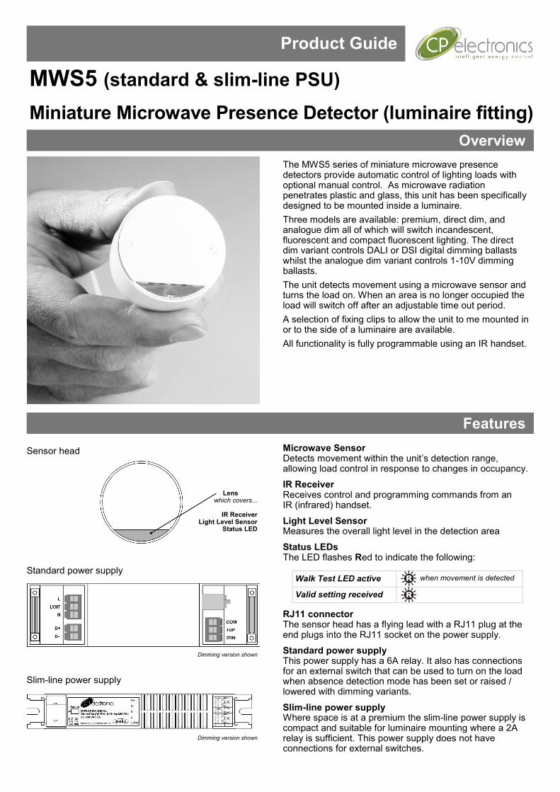
Detection diagram
Please note that these approximate distances will apply with the sensitivity set to maximum.
3
The detector should be sited so that the occupants of the room fall inside the detection pattern shown opposite). Please note that when ceiling mounting, the recommended ceiling height of the sensor head is 2.4m.
• Avoid direct sunlight entering the sensor.
• Do not site within 1m of forced air heating or ventilation.
• Do not fix to a vibrating surface.
• Avoid metallic objects directly in front of the sensor head.
• Do not fit to a suspended luminaire.
Installation
Detection mode
• Presence When movement is detected the load will automatically turn on. When the area is no longer occupied the load will automatically switch off after an adjustable time period.
• Absence (standard power supply only) The load is manually switched on. When the area is no longer occupied the load will automatically switch off after the adjustable time period has elapsed.
• Switch operation:
PRM single switch: short press turn on, long press turn off.
MWS5-DD & MWS5-AD single switch: short press turn on, short press turn off, press and hold cycles dimming.
MWS5-DD & MWS5-AD two way switch: up button short press turns on, press and hold to dims up. Down button short press turns off, press and hold dims down.
In either case, sensitivity to movement of the microwave sensor can be adjusted using the Sensitivity parameter.
HINT: To assist in setting the Sensitivity, turn on the Walk Test LED which will flash red when movement is detected.
Switch Level On/Off
Occupancy detection can be made dependant on the ambient light level using the Lux On Level and Lux Off Level parameters.
Maintained Illuminance (daylight harvesting) - DD and AD variants only The detector measures the overall light level in the detection area and calculates the correct output for the luminaires, to achieve a preset lux level (maintained illuminance or daylight harvesting).
Burn-in - DD and AD variants only
• Overview
It is a requirement of many fluorescent lamp manufacturers to have the lamps on at maximum output for a period of time to guarantee lamp life (refer to the manufacturer’s datasheet for details). As the MWS5-DD & AD are able to dim the lamps using DALI/DSI or 1-10V, the products provide a facility to disable this for a given period of time.
• Operation
By setting the “Burn in” parameter, you can select a time during which the lamps are not allowed to deviate from maximum output. The unit counts the time, and even remembers how long has elapsed in the event of a power failure. To cancel the burn in function, simply select a time of 0. Note that when the lamps are changed, the burn in time should be set again.
Sensor functionality
Burn-in - DD and AD variants only
4
Ø23mm
Ø3.5m
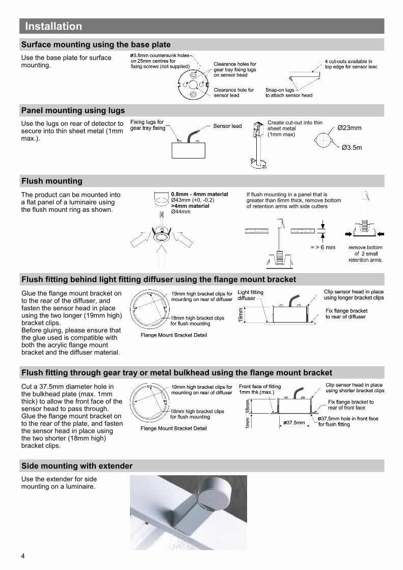
Panel mounting using lugs
Flush mounting
The product can be mounted into a flat panel of a luminaire using the flush mount ring as shown.
Flush fitting behind light fitting diffuser using the flange mount bracket
Use the lugs on rear of detector to secure into thin sheet metal (1mm max.).
Glue the flange mount bracket on to the rear of the diffuser, and fasten the sensor head in place using the two longer (19mm high) bracket clips. Before gluing, please ensure that the glue used is compatible with both the acrylic flange mount bracket and the diffuser material.
Flush fitting through gear tray or metal bulkhead using the flange mount bracket
Cut a 37.5mm diameter hole in the bulkhead plate (max. 1mm thick) to allow the front face of the sensor head to pass through. Glue the flange mount bracket on to the rear of the plate, and fasten the sensor head in place using the two shorter (18mm high) bracket clips.
Surface mounting using the base plate
Use the base plate for surface mounting.
Installation
Side mounting with extender
Use the extender for side mounting on a luminaire.
0.8mm - 4mm material Ø43mm (+0, -0.2) >4mm material Ø44mm
If flush mounting in a panel that is greater than 6mm thick, remove bottom of retention arms with side cutters
Create cut-out into thin sheet metal (1mm max)
5
The UNLCDHS has the ability to read back the settings stored in a device. To read back individual parameters
• Navigate to the parameter and press the ‘R’ (Read) button whilst pointing at the device. The handset will click when the parameter has been read back, the device will flash its LED, and the value will be shown against the parameter in the menu.
To read back all of the parameters in a menu
• Press and hold the ‘R’ (Read) button for more than 1 second.
• The handset will click every time a parameter is received
• The device will show multiple flashes of its LED
• All of the values will be shown against the parameters in the menu.
• The individual parameters may be edited and then saved as a ‘Macro’. Notes
• If a parameter(s) has been missed because of a communication error, the missing value(s) is replaced by dashes.
• When reading back, the Channel 1 relay (where fitted) will temporarily be switched off, and will return to it’s normal state 2 seconds after the read back has been completed.
Readback function (only with UNLCDHS handset )
When power is applied to the unit, the load will turn on immediately. Set the timeout to 10 seconds, vacate the room or remain very still and wait for the load to switch off . Check that the load switches on when movement is detected. The unit is now ready for programming.
Power-up test procedure
What if the load does not turn ON?
• Check that the live supply to the circuit is good.
• Check that the load is functioning by bypassing the sensor (e.g. link terminals L and L/ Out).
• If the detection range is smaller than expected, check the diagram on page 2. Rotating the sensor slightly may improve the detection range.
HINT: The Walk Test LED function can be used to check that the unit is detecting movement in the required area. What if the load does not turn OFF?
• Ensure that the area is left unoccupied for longer than the Time Out Period.
• Ensure that the sensor is not adjacent to circulating air, heaters or lamps.
• The unit may pick up movement through glass, thin partitions or walls and “false trigger”. Reduce the sensitivity using the sensitivity settings .
Fault finding
6
Wiring diagrams - standard power supply
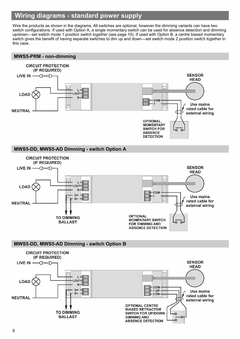
Wire the products as shown in the diagrams. All switches are optional, however the dimming variants can have two switch configurations. If used with Option A, a single momentary switch can be used for absence detection and dimming up/down—set switch mode 1 position switch together (see page 10). If used with Option B, a centre biased momentary switch gives the benefit of having separate switches to dim up and down—set switch mode 2 position switch together in this case.
MWS5-PRM - non-dimming
MWS5-DD, MWS5-AD Dimming - switch Option A
MWS5-DD, MWS5-AD Dimming - switch Option B
7
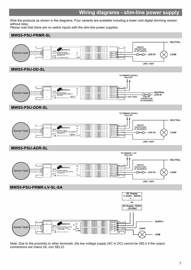
Wiring diagrams - slim-line power supply
MWS5-PSU-DD-SL
MWS5-PSU-PRMR-SL
MWS5-PSU-ADR-SL
MWS5-PSU-DDR-SL
Wire the products as shown in the diagrams. Four variants are available including a lower cost digital dimming version without relay. Please note that there are no switch inputs with the slim-line power supplies.
MWS5-PSU-PRMR-LV-SL-SA
Note. Due to the proximity to other terminals ,the low voltage supply (AC or DC) cannot be SELV if the output connections are mains (ie, non SELV).
8
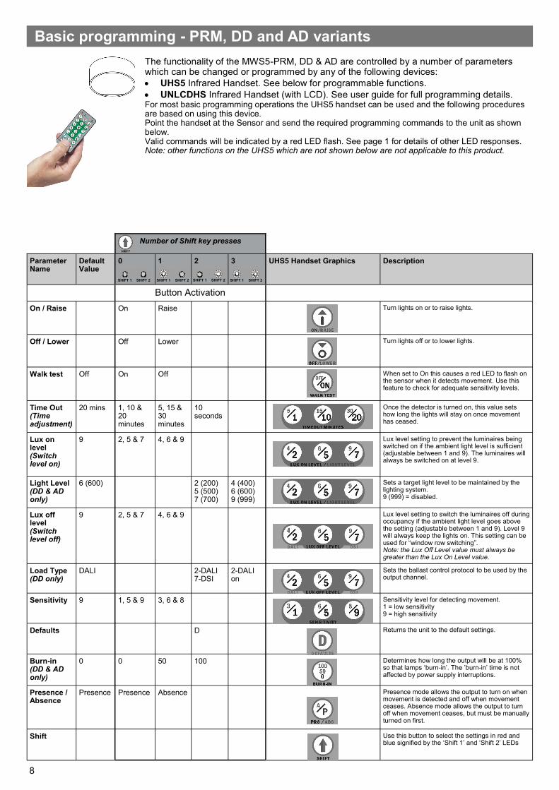
Basic programming - PRM, DD and AD variants
Parameter Name
Default Value
0 1 2 3 UHS5 Handset Graphics Description
Button Activation
On / Raise On Raise Turn lights on or to raise lights.
Off / Lower Off Lower Turn lights off or to lower lights.
Walk test Off On Off When set to On this causes a red LED to flash on the sensor when it detects movement. Use this feature to check for adequate sensitivity levels.
Time Out (Time adjustment)
20 mins 1, 10 & 20 minutes
5, 15 & 30 minutes
10 seconds
Once the detector is turned on, this value sets how long the lights will stay on once movement has ceased.
Lux on level (Switch level on)
9 2, 5 & 7 4, 6 & 9 Lux level setting to prevent the luminaires being switched on if the ambient light level is sufficient (adjustable between 1 and 9). The luminaires will always be switched on at level 9.
Light Level (DD & AD only)
6 (600) 2 (200) 5 (500) 7 (700)
4 (400) 6 (600) 9 (999)
Sets a target light level to be maintained by the lighting system. 9 (999) = disabled.
Lux off level (Switch level off)
9 2, 5 & 7 4, 6 & 9 Lux level setting to switch the luminaires off during occupancy if the ambient light level goes above the setting (adjustable between 1 and 9). Level 9 will always keep the lights on. This setting can be used for “window row switching”. Note: the Lux Off Level value must always be greater than the Lux On Level value.
Load Type (DD only)
DALI 2-DALI 7-DSI
2-DALI on
Sets the ballast control protocol to be used by the output channel.
Sensitivity 9 1, 5 & 9 3, 6 & 8 Sensitivity level for detecting movement. 1 = low sensitivity 9 = high sensitivity
Defaults D Returns the unit to the default settings.
Burn-in (DD & AD only)
0 0 50 100 Determines how long the output will be at 100% so that lamps ‘burn-in’. The ’burn-in’ time is not affected by power supply interruptions.
Presence / Absence
Presence Presence Absence Presence mode allows the output to turn on when movement is detected and off when movement ceases. Absence mode allows the output to turn off when movement ceases, but must be manually turned on first.
Shift Use this button to select the settings in red and blue signified by the ‘Shift 1’ and ‘Shift 2’ LEDs
Number of Shift key presses
The functionality of the MWS5-PRM, DD & AD are controlled by a number of parameters which can be changed or programmed by any of the following devices:
• UHS5 Infrared Handset. See below for programmable functions.
• UNLCDHS Infrared Handset (with LCD). See user guide for full programming details. For most basic programming operations the UHS5 handset can be used and the following procedures are based on using this device. Point the handset at the Sensor and send the required programming commands to the unit as shown below. Valid commands will be indicated by a red LED flash. See page 1 for details of other LED responses. Note: other functions on the UHS5 which are not shown below are not applicable to this product.
SHIFT 1 SHIFT 2 SHIFT 1 SHIFT 2 SHIFT 1 SHIFT 2 SHIFT 1 SHIFT 2
9
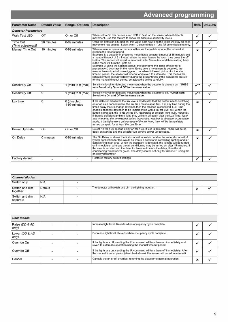
Advanced programming
Parameter Name Default Value Range / Options Description
Detector Parameters
Walk Test LED Off On or Off When set to On this causes a red LED to flash on the sensor when it detects movement. Use this feature to check for adequate sensitivity levels. ✓ ✓
Time Out (Time adjustment)
20 minutes 0-99 minutes Once the detector is turned on, this value sets how long the lights will stay on once movement has ceased. Select 0 for 10 second delay – use for commissioning only. ✓ ✓
Manual Time Out 10 minutes 0-99 minutes When a manual operation occurs, either via the switch input or the infrared, it invokes the timeout period. Example 1: a detector in presence mode has a detector timeout of 15 minutes and a manual timeout of 3 minutes. When the user leaves the room they press the off button. The sensor will revert to automatic after 3 minutes, and then walking back in the room will turn the lights on. Example 2: using the settings above, the user turns the lights off (say for a presentation) but stays in the room. Every time a movement is detected, the manual timeout period is re-triggered, but when it doesn’t pick up for the short timeout period, the sensor will timeout and revert to automatic. This means the lights may turn on inadvertently during the presentation, if the occupants are still for the manual timeout period, so adjust the timing carefully.
✓
Sensitivity On 9 1 (min) to 9 (max) Sensitivity level for detecting movement when the detector is already on. *UHS5 sets Sensitivity On and Off to the same value. ✓* ✓
Sensitivity Off 9 1 (min) to 9 (max) Sensitivity level for detecting movement when the detector is off. *UHS5 sets Sensitivity On and Off to the same value. ✓* ✓
Lux time 0 0 (disabled) 1-99 minutes
If the detector measures the lux level and decides that the output needs switching on or off as a consequence, the lux time must elapse first. If at any time during the timed delay the lux change reverses then the process is cancelled. Lux Time enables absence detection to be implemented with a lux off level set. When the button is pressed, the lights will go on, regardless of ambient light level. However, if there is sufficient ambient light, they will turn off again after the Lux Time. Note that whenever the an external switch is pressed, whether in absence or presence mode, if the lights were out because of the lux level, they will be immediately turned on again for at least the Lux Time.
✓
Power Up State On On or Off Select No for a 30 second delay on start up. If Yes is selected, there will be no delay on start up and the detector will always power up detecting. ✓
On Delay 0 minutes 0-99 minutes The On Delay to allows the first channel to switch on after the second channel. A typical application for this would be where a detector is controlling lighting and air conditioning in an area. When the occupant is detected, the lighting will be turned on immediately, whereas the air conditioning may be turned on after 15 minutes. If the area is vacated and the detector times out before the delay, then the air conditioning would never go on. The delay can be set only for channel 1 using the on delay parameter.
✓
Factory default - - Restores factory default settings ✓ ✓
User Modes
Raise (DD & AD only)
- - Increase light level. Reverts when occupancy cycle complete. ✓ ✓
Lower (DD & AD only)
- - Decrease light level. Reverts when occupancy cycle complete. ✓ ✓
Override On - - If the lights are off, sending the IR command will turn them on immediately and revert to automatic operation using the manual timeout period. ✓ ✓
Override Off - - If the lights are on, sending the IR command will turn them off immediately. After the manual timeout period (described above), the sensor will revert to automatic. ✓ ✓
Cancel - - Cancels the on or off override, returning the detector to normal operation. ✓
Channel Modes
Switch only N/A -
Switch and dim together
Default - The detector will switch and dim the lighting together. ✓
Switch and dim separate
N/A -
10
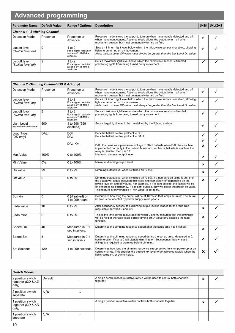
Parameter Name Default Value Range / Options Description
Channel 1 –Switching Channel
Detection Mode Presence Presence or Absence
Presence mode allows the output to turn on when movement is detected and off when movement ceases. Absence mode allows the output to turn off when movement ceases, but must be manually turned on first.
✓ ✓
Lux on level (Switch level on)
9 1 to 9 For a higher resolution a scale of 101-199 is available
Sets a minimum light level below which the microwave sensor is enabled, allowing lights to be turned on by movement. Note: the Lux Level Off value must always be greater than the Lux Level On value.
✓ ✓
Lux off level (Switch level off)
9 1 to 9 For a higher resolution a scale of 101-199 is available
Sets a maximum light level above which the microwave sensor is disabled, preventing lights from being turned on by movement. ✓ ✓
Advanced programming
Switch Modes
2 position switch together (DD & AD only)
Default - A single centre biased retractive switch will be used to control both channels together. ✓
2 position switch separate
N/A -
1 position switch together (DD & AD only)
- - A single position retractive switch controls both channels together. ✓
1 position switch separate
N/A -
Channel 2 -Dimming Channel (DD & AD only)
Detection Mode Presence Presence or Absence
Presence mode allows the output to turn on when movement is detected and off when movement ceases. Absence mode allows the output to turn off when movement ceases, but must be manually turned on first.
✓ ✓
Lux on level (Switch level on)
9 1 to 9 For a higher resolution a scale of 101-199 is available
Sets a minimum light level below which the microwave sensor is enabled, allowing lights to be turned on by movement. Note: the Lux Level Off value must always be greater than the Lux Level On value.
✓ ✓
Lux off level (Switch level off)
9 1 to 9 For a higher resolution a scale of 101-199 is available
Sets a maximum light level above which the microwave sensor is disabled, preventing lights from being turned on by movement. ✓ ✓
Light Level (maintained illuminance)
600 1 to 998 (999 disabled)
Sets a target light level to be maintained by the lighting system. ✓ ✓
Load Type (DD only)
DALI DSI DALI DALI On
Sets the ballast control protocol to DSI. Sets the ballast control protocol to DALI. DALI On provides a permanent voltage to DALI ballasts when DALI has not been implemented correctly in the ballast. Maximum number of ballasts is 4 unless the relay is disabled then it is 10.
✓
✓
✓
✓
✓
Max Value 100% 0 to 100% Maximum dimming output level. ✓
Min Value 0% 0 to 100% Minimum dimming output level. ✓
On value 99 0 to 99 Dimming output level when switched on (0-99). ✓
Off value 0 0 to 99 Dimming output level when switched off (0-99). If a non-zero off value is set, then the output will toggle between this value and completely off depending on the switch level on and off values. For example, if it is light outside, the fittings will be off if there is no occupancy. If it is dark outside, they will adopt the preset off value. This feature is only enabled if ‘Min value’ is set to 99.
✓
Burn-in 0 0 (disabled) or 1 to 999 hours
Determines how long the output will be at 100% so that lamps ‘burn-in’. The ’burn-in’ time is not affected by power supply interruptions. ✓ ✓
Fade value 10 0 to 99 After occupancy ceases, this dimming output level is loaded for the fade time (adjustable between 0 and 99). ✓
Fade mins 0 0 to 99 This is the time period (adjustable between 0 and 99 minutes) that the luminaire will be held at the fade value before turning off. A value of 0 disables the fade function.
✓
Speed On 40 Measured in 0.1 sec intervals.
Determines the dimming response speed after the setup time has finished. ✓
Speed Set 5 Measured in 0.1 sec intervals.
Determines the dimming response speed during the set up time. Measured in 0.1 sec intervals. If set to 0 will disable dimming for “Set seconds” below, used if fittings are required to warm up before dimming.
✓
Set Seconds 120 1 to 999 seconds Determines how long the dimming response set-up period lasts on power-up or on setting change. This enables the desired lux level to be achieved rapidly when the lights come on, or during setup.
✓
11
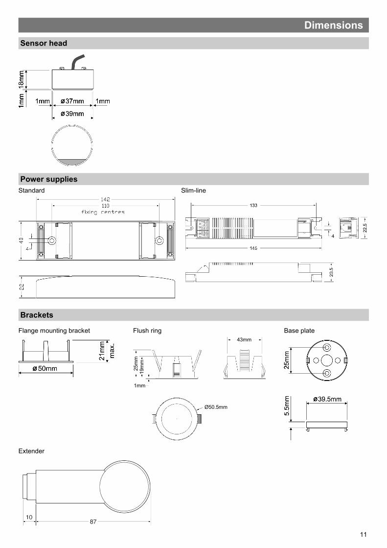
Dimensions
Flange mounting bracket
Extender
Standard Slim-line
Sensor head
Power supplies
Brackets
Base plate Flush ring
25m
m
19m
m
43mm
1mm
Ø50.5mm
12
Due to our policy of continual product improvement CP Electronics reserves the right to alter the specification of this product without prior notice.
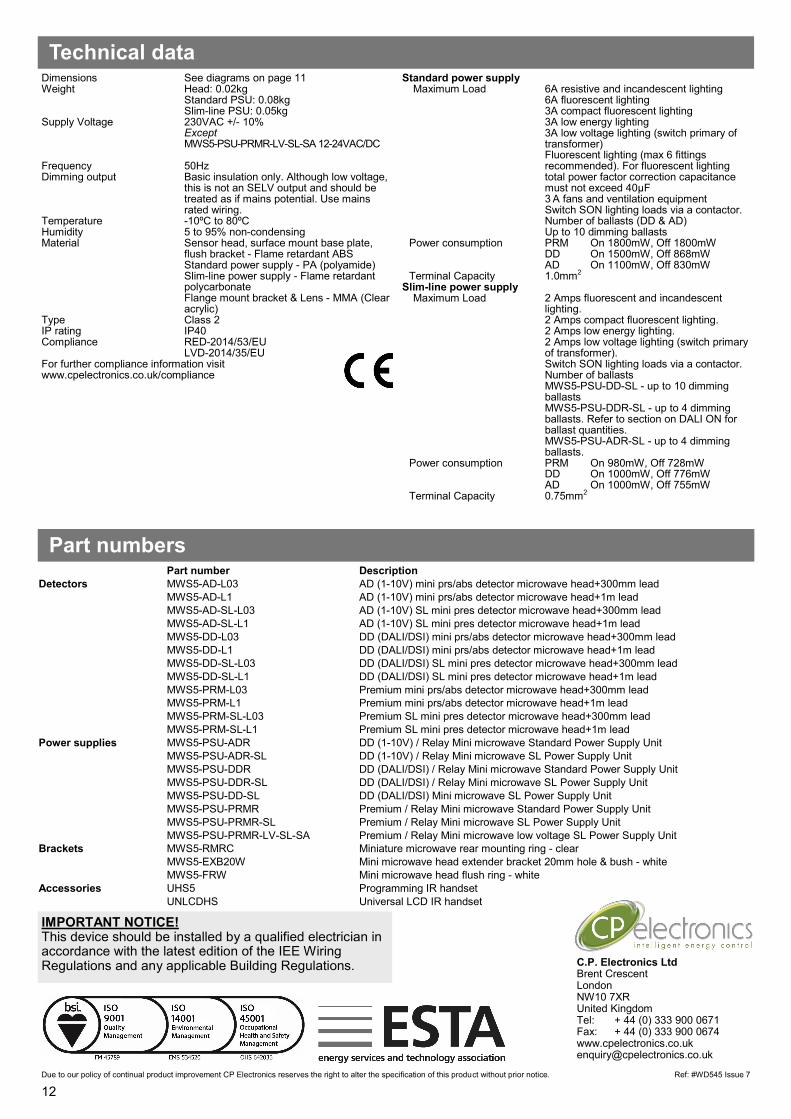
Dimensions See diagrams on page 11 Weight Head: 0.02kg Standard PSU: 0.08kg Slim-line PSU: 0.05kg Supply Voltage 230VAC +/- 10%
Except MWS5-PSU-PRMR-LV-SL-SA 12-24VAC/DC Frequency 50Hz Dimming output Basic insulation only. Although low voltage,
this is not an SELV output and should be treated as if mains potential. Use mains rated wiring.
Temperature -10ºC to 80ºC Humidity 5 to 95% non-condensing Material Sensor head, surface mount base plate,
flush bracket - Flame retardant ABS Standard power supply - PA (polyamide) Slim-line power supply - Flame retardant polycarbonate
Flange mount bracket & Lens - MMA (Clear acrylic)
Type Class 2 IP rating IP40 Compliance RED-2014/53/EU
LVD-2014/35/EU For further compliance information visit www.cpelectronics.co.uk/compliance
Standard power supply Maximum Load 6A resistive and incandescent lighting
6A fluorescent lighting 3A compact fluorescent lighting 3A low energy lighting 3A low voltage lighting (switch primary of
transformer) Fluorescent lighting (max 6 fittings
recommended). For fluorescent lighting total power factor correction capacitance must not exceed 40μF
3 A fans and ventilation equipment Switch SON lighting loads via a contactor.
Number of ballasts (DD & AD) Up to 10 dimming ballasts
Power consumption PRM On 1800mW, Off 1800mW DD On 1500mW, Off 868mW AD On 1100mW, Off 830mW
Terminal Capacity 1.0mm2 Slim-line power supply
Maximum Load 2 Amps fluorescent and incandescent lighting. 2 Amps compact fluorescent lighting. 2 Amps low energy lighting. 2 Amps low voltage lighting (switch primary of transformer). Switch SON lighting loads via a contactor. Number of ballasts MWS5-PSU-DD-SL - up to 10 dimming ballasts MWS5-PSU-DDR-SL - up to 4 dimming ballasts. Refer to section on DALI ON for ballast quantities. MWS5-PSU-ADR-SL - up to 4 dimming ballasts.
Power consumption PRM On 980mW, Off 728mW DD On 1000mW, Off 776mW AD On 1000mW, Off 755mW
Terminal Capacity 0.75mm2
Technical data
Part numbers
C.P. Electronics Ltd Brent Crescent London NW10 7XR United Kingdom Tel: + 44 (0) 333 900 0671 Fax: + 44 (0) 333 900 0674 www.cpelectronics.co.uk [email protected]
Ref: #WD545 Issue 7
IMPORTANT NOTICE! This device should be installed by a qualified electrician in accordance with the latest edition of the IEE Wiring Regulations and any applicable Building Regulations.
Part number Description
Detectors MWS5-AD-L03 AD (1-10V) mini prs/abs detector microwave head+300mm lead
MWS5-AD-L1 AD (1-10V) mini prs/abs detector microwave head+1m lead
MWS5-AD-SL-L03 AD (1-10V) SL mini pres detector microwave head+300mm lead
MWS5-AD-SL-L1 AD (1-10V) SL mini pres detector microwave head+1m lead
MWS5-DD-L03 DD (DALI/DSI) mini prs/abs detector microwave head+300mm lead
MWS5-DD-L1 DD (DALI/DSI) mini prs/abs detector microwave head+1m lead
MWS5-DD-SL-L03 DD (DALI/DSI) SL mini pres detector microwave head+300mm lead
MWS5-DD-SL-L1 DD (DALI/DSI) SL mini pres detector microwave head+1m lead
MWS5-PRM-L03 Premium mini prs/abs detector microwave head+300mm lead
MWS5-PRM-L1 Premium mini prs/abs detector microwave head+1m lead
MWS5-PRM-SL-L03 Premium SL mini pres detector microwave head+300mm lead
MWS5-PRM-SL-L1 Premium SL mini pres detector microwave head+1m lead
Power supplies MWS5-PSU-ADR DD (1-10V) / Relay Mini microwave Standard Power Supply Unit
MWS5-PSU-ADR-SL DD (1-10V) / Relay Mini microwave SL Power Supply Unit
MWS5-PSU-DDR DD (DALI/DSI) / Relay Mini microwave Standard Power Supply Unit
MWS5-PSU-DDR-SL DD (DALI/DSI) / Relay Mini microwave SL Power Supply Unit
MWS5-PSU-DD-SL DD (DALI/DSI) Mini microwave SL Power Supply Unit
MWS5-PSU-PRMR Premium / Relay Mini microwave Standard Power Supply Unit
MWS5-PSU-PRMR-SL Premium / Relay Mini microwave SL Power Supply Unit
MWS5-PSU-PRMR-LV-SL-SA Premium / Relay Mini microwave low voltage SL Power Supply Unit
Brackets MWS5-RMRC Miniature microwave rear mounting ring - clear
MWS5-EXB20W Mini microwave head extender bracket 20mm hole & bush - white
MWS5-FRW Mini microwave head flush ring - white
Accessories UHS5 Programming IR handset
UNLCDHS Universal LCD IR handset
Related Documents