MODEL NUMBERS MWE-9501 MWEH-9501 MWEF-9501 MWEL-9501 MWER-9501 MWEFH-9501 SERVICE MANUAL NOTE: This manual pertains to all grill models listed above. The reader/operator must interpret its contents to applicable needs. However, if there is any question of interpretation of any literature pertaining to Garland grills, please contact our Customer Service Department at one of the phone numbers listed above. WARNING: IMPROPER INSTALLATION, ADJUSTMENT, ALTERATION, SERVICE OR MAINTENANCE CAN CAUSE PROPERTY DAMAGE, INJURY OR DEATH. READ THE INSTALLATION, OPERATING AND MAINTENANCE INSTRUCTIONS THOROUGHLY BEFORE INSTALLING OR SERVICING THIS EQUIPMENT. PLEASE READ ALL SECTIONS OF THIS MANUAL AND RETAIN FOR FUTURE REFERENCE. CAUTION: THIS EQUIPMENT MUST ONLY BE OPERATED UNDER AN APPROVED HOOD SYSTEM THIS EQUIPMENT “MUST” BE INSTALLED AND COMMISSIONED BY A PROFESSIONAL FACTORY TRAINED TECHNICIAN ® Rev 7e P/N 1881010 IN(072105) MANUFACTURED EXCLUSIVELY FOR McDonald's BY GARLAND COMMERCIAL INDUSTRIES, INC. 185 EAST SOUTH STREET FREELAND, PENNSYLVANIA 18224 TOLL FREE: (800) 446-8367 PHONE: (570) 636-1000 FAX: (570) 636-9874 Come visit us on the web at www.garland-group.com E-mail: [email protected]

Welcome message from author
This document is posted to help you gain knowledge. Please leave a comment to let me know what you think about it! Share it to your friends and learn new things together.
Transcript
MODEL NUMBERSMWE-9501
MWEH-9501MWEF-9501MWEL-9501MWER-9501
MWEFH-9501
SERVICE MANUAL
NOTE: This manual pertains to all grill models listed above. The reader/operator must interpret its contents to applicable needs. However, if there is any question of interpretation of any literature
pertaining to Garland grills, please contact our Customer Service Department at one of the phonenumbers listed above.
WARNING:IMPROPER INSTALLATION, ADJUSTMENT, ALTERATION, SERVICE OR MAINTENANCE CAN CAUSE PROPERTY
DAMAGE, INJURY OR DEATH. READ THE INSTALLATION, OPERATING AND MAINTENANCE INSTRUCTIONS THOROUGHLY BEFORE INSTALLING OR SERVICING THIS EQUIPMENT.
PLEASE READ ALL SECTIONS OF THIS MANUAL AND RETAIN FOR FUTURE REFERENCE.
CAUTION: THIS EQUIPMENT MUST ONLY BE OPERATED UNDER AN APPROVED HOODSYSTEM
THIS EQUIPMENT “MUST” BE INSTALLED AND COMMISSIONED BY A PROFESSIONALFACTORY TRAINED TECHNICIAN
®
Rev 7e P/N 1881010 IN(072105)
MANUFACTURED EXCLUSIVELY FORMcDonald's
BYGARLAND COMMERCIAL INDUSTRIES, INC.
185 EAST SOUTH STREETFREELAND, PENNSYLVANIA 18224
TOLL FREE: (800) 446-8367PHONE: (570) 636-1000
FAX: (570) 636-9874Come visit us on the web at
www.garland-group.comE-mail: [email protected]
2
TABLE OF CONTENTS
WARRANTY ........................................................................................................................................................................................................................ 4INTRODUCTION ............................................................................................................................................................................................................. 4SAFETY .................................................................................................................................................................................................................................. 4SHIPPING DAMAGE CLAIM PROCEDURE .................................................................................................................................................. 5CLEANING AND MAINTENANCE ....................................................................................................................................................................... 5SPECIFICATIONS ........................................................................................................................................................................................................... 7
FULL SIZE ELECTRIC GRILL MODEL MWE-9501 W/ 2 SPEED FAN .............................................................................................. 7HALF SIZE ELECTRIC GRILL MODEL MWEH-9501 W/ 2 SPEED FAN .......................................................................................... 8HALF & HALF FULL SIZE LEFT SIDE CLAM ONLY MODEL MWEL-9501 .................................................................................. 9HALF & HALF FULL SIZE RIGHT SIDE CLAM ONLY MODEL MWER-9501 .............................................................................. 10FULL SIZE FLAT GRILL MODEL MWEF-9501 ........................................................................................................................................ 11
RELEASE MATERIAL INSTALLATION .......................................................................................................................................................... 12RELEASE MATERIAL INSTALLATION (OPTIONAL) ........................................................................................................................... 132-SPEED FAN INTERFACE INFORMATION ................................................................................................................................................ 15UNIT INSTALLATION ................................................................................................................................................................................................. 16PLATEN ZEROING ........................................................................................................................................................................................................ 17OPTIONAL ACCESSORIES ...................................................................................................................................................................................... 19CLAMSHELL GRILL CONTROLS ...................................................................................................................................................................... 20CONTROLES DE LA PARRILLA DE DOBLE COCCIÓN ..................................................................................................................... 20DESCRIPTION OF GRILL CONTROLS ........................................................................................................................................................... 21
General Overview ................................................................................................................................................................................... 21The Master Power (Pushbutton (ON / OFF) .......................................................................................................................................... 21Indicator Lights ....................................................................................................................................................................................... 21Up Arrow Button - Two Functions .......................................................................................................................................................... 21Right Arrow Button - Two Functions ...................................................................................................................................................... 21Program Mode Button - Two Functions ................................................................................................................................................. 21Menu Button - Two Functions ................................................................................................................................................................ 21Temperature / Function Button - Two Functions .................................................................................................................................... 21Standby Button - Black ........................................................................................................................................................................... 22
NORMAL OPERATING MODES ........................................................................................................................................................................... 22Preheat Mode (Eprom 6.20 and higher) ................................................................................................................................................. 22To Cook in Clam Grill Mode: ................................................................................................................................................................. 22Cancel / Raise Button - Green ................................................................................................................................................................ 22To Cook in Flat Grill Mode: ................................................................................................................................................................... 22Standby Mode: ........................................................................................................................................................................................ 23EXIT the Standby Mode: ......................................................................................................................................................................... 23Standby Alarm (Version 6.20 and higher) .............................................................................................................................................. 23To Display the Current Temperature ...................................................................................................................................................... 23To View Settings for a Menu Item: .......................................................................................................................................................... 23To Reset Factory Defaults ...................................................................................................................................................................... 23To Clean the Grill: .................................................................................................................................................................................. 24Breakfast to Lunch Transition (Transition Cooking) .............................................................................................................................. 24Multi-Stage Cooking ............................................................................................................................................................................... 24
PROGRAM LOGIC CHART ..................................................................................................................................................................................... 25SYSTEM SETUP .................................................................................................................................................................................................. 26
To Display Temperatures in F or C ........................................................................................................................................................ 26To Change the Speaker Volume (High / Low) ........................................................................................................................................ 26To Change the Gap Calibration ............................................................................................................................................................. 26To Enable / Disable Start Delay ............................................................................................................................................................. 26To Change Start Delay Timer ................................................................................................................................................................. 27To Change the Standby Alert Feature - EPROM Chip Ver. 6.20 and higher ......................................................................................... 27To Enable / Disable Multi-Stage Cooking - EPROM Chip Ver. 7.XX and higher ................................................................................. 27
MENU ITEMS ....................................................................................................................................................................................................... 28To Add or Delete a Menu Item ............................................................................................................................................................... 28To Change the Remove Time .................................................................................................................................................................. 28To Change the Remove Time Alarm (Auto/Manual) ............................................................................................................................... 28To Change the Sear Time ........................................................................................................................................................................ 29To Change the Sear Time Alarm (Auto/Manual) .................................................................................................................................... 29To Change the Toast Buns Time .............................................................................................................................................................. 29To Change the Toast Buns Alarm (Auto/Manul) .................................................................................................................................... 29To Change Turn Time .............................................................................................................................................................................. 30To Change Turn In Alarm (Auto / Manual) ............................................................................................................................................ 30To Change the grill surface set temperature .......................................................................................................................................... 30To Change the upper platen set temperature .......................................................................................................................................... 31To Change the Gap Setting ..................................................................................................................................................................... 31
3
To Enable High Limit Test - GRILL SURFACE (Chip V. 3.52 and 4.0* ONLY) .................................................................................... 31To Enable High Limit Test - PLATEN (Chip V. 3.52 and 4.0* ONLY) .................................................................................................. 31
TO ADD / PROGRAM NEW MENU ITEMS .................................................................................................................................................... 32To Add / Program an [Option Menu - CLAM] ....................................................................................................................................... 32To Add / Program an [OPTION MENU - FLAT] ................................................................................................................................... 33
PROBE CALIBRATION .............................................................................................................................................................................................. 34TROUBLESHOOTING ................................................................................................................................................................................................. 36
IN STORE TROUBLESHOOTING GUIDE .................................................................................................................................................. 36POSSIBLE ERROR MESSAGES ..................................................................................................................................................................... 37TECHNICAL TROUBLESHOOTING ............................................................................................................................................................ 38
Master Power (ON / OFF) Switch turned ON - Power telite is not lit .................................................................................................. 38Low Internal Product Temperatures ....................................................................................................................................................... 38Controller Displays “Too Hot” .............................................................................................................................................................. 39Controller Displays “EPROM CORRUPT” .......................................................................................................................................... 39Controller Displays “FAULTY ELEMENT OR SHORTED PROBE” - Only 1 or 2 zones LED lights are RED ................................. 40Controller displays “OPEN PROBE” .................................................................................................................................................... 41Controller Displays “HIGH LIMIT” ...................................................................................................................................................... 41Controller displays “FAULTY ELEMENT OR SHORTED PROBE” - All LED’s are red ..................................................................... 42Inconsistant or erratic internal product temperature ............................................................................................................................. 42Controller Display is BLANK, Main Power (ON / OFF) telite IS LIT .................................................................................................. 43Main Power Switch (ON / OFF) is on - Grill is on - Exhaust fan is not running ................................................................................. 44Master Power (ON / OFF) Switch turned ON - Power LIght in On - Grill is not heating ................................................................... 45Controller Displays “MOTOR OVERCURRENT” - Platen does not move at all ................................................................................. 46Controller Displays “MOTOR OVERCURRENT” - Platen goes up, and then half way down ............................................................ 46
MILLIVOLT CONVERSION CHART ................................................................................................................................................................. 47PARTS IDENTIFICATION ......................................................................................................................................................................................... 48
Exploded View - Exterior ........................................................................................................................................................................ 48Control Panel Assembly .......................................................................................................................................................................... 48Upper Platen Assembly ........................................................................................................................................................................... 50Interior Grill ........................................................................................................................................................................................... 52Lift Assembly ........................................................................................................................................................................................... 54Lift Assembly - Exploded Views .............................................................................................................................................................. 55
CONTROLLER MENU ITEMS ............................................................................................................................................................................... 58CONTROLLER MENU ITEMS (EPROM CHIP VER. 7.XX) ................................................................................................................ 60WIRING DIAGRAMS ................................................................................................................................................................................................... 62
Full Size MWE-9501 Wiring diagram - SK98-003 ................................................................................................................................. 62Full size MWE-9501 Wiring diagram - SK98-004 ................................................................................................................................. 63MWE/MWEH-9501 Control Wiring Diagram - 18597S02 .................................................................................................................... 64MWE-9501 Element Wiring Diagram - 18597S01 ................................................................................................................................. 65MWEH-9501 Element Wiring Diagram - 18597S03 .............................................................................................................................. 66MWEF-9501 Control Wiring Diagram - 18597S05 ............................................................................................................................... 67MWEF-9501 Element Wiring Diagram - 18597S04 .............................................................................................................................. 68
TEMPERATURE CONVERSION (F / C) ........................................................................................................................................................... 69MANUAL CORRECTIONS AND MODIFICATIONS ................................................................................................................................. 71
4
WARRANTYThis warranty covers defects in material and workmanship under normal use providing that:
a) the equipment has not been accidentally or intentionally damaged, altered or misused.
b) the equipment is properly installed, adjusted, operated and maintained in accordance with national and local codes and in accordance with the installation instructions provided with this product.
c) the warranty serial number affixed to the appliance by us has not been defaced, obliterated or removed.
d) an acceptable report for any claim under this warranty is supplied to us.
The equipment warranty coverage remains in force for one (1) year (parts and labor) from the date the equipment is put into operation and two (2) years (parts only) for the microprocessor controller, motor speed controller and upper platen (aluminum casting and shroud).
The Garland Group agrees to repair or replace, at it’s option, any part that proves to be defective in material or workmanship at no charge for the part or normal labor.
We assume no responsibility for installation, adjustments, diagnosis, or normal maintenance such as: lubrication of springs or valves. We exclude failures caused by erratic voltage or gas supplies. We assume no responsibility for travel costs beyond 100 miles round trip, travel other than overland, and overtime costs of repair. We exclude broken glass, paint and porcelain finish, surface rust, gasket material, ceramic material, light bulbs and fuses from normal coverage. We exclude damage or dysfunction caused by fire, flood, and like “Acts of God” that are beyond the control of The Garland Group.
The Garland Group’s liability on a claim of warranty shall not exceed the price of the material and/or service, which caused the claim. This warranty is limited and is in lieu of all other warranties, expressed or implied. The Garland Group, our employees, or our agents shall not be held liable for any claims of personal injury or consequential damage or loss. This warranty gives you specific legal rights, and you may have other rights which vary from state to state.
INTRODUCTION
Always follow these safety precautions when operating the clamshell grill.
THIS GRILL MUST be operated by persons who have been given adequate training.
CAUTION: THIS EQUIPMENT MUST ONLY BE OPERATED UNDER AN APPROVED HOOD SYSTEM.
DO NOT OPERATE THE GRILL UNLESS IT HAS BEEN COMMISSIONED (START-UP) BY A FACTORY AUTHORIZED SERVICE CENTER.
DO NOT operate the grill without reading this operation manual.
DO NOT operate the clamshell grill unless it has been properly installed and grounded.
DO NOT operate the clamshell grill unless all service and access panels are in place and fastened properly.
The Garland clamshell grill is a semi-automatic cooking appliance. The upper platen is lowered automatically, following the manual; two-handed initiation of the cooking cycle, and the upper platen is raised automatically upon completion of the cooking cycle.
When two sided cooking, the area between the upper platen and the griddle plate should be regarded as a "danger zone". During two sided cooking the operator must not be within this danger zone. When used as a flat grill, then this area is no longer a danger zone, the platens do not move.
For whatever reason, be it cleaning, maintenance, normal operation, any exposed person must use extreme caution if within this danger zone.
In two side cooking the upper platen remains in the lowered position by nature of it's own weight. It is not locked down. It can be raised by lifting of the handle on the front of the platen, which pivots the platen about its rear mounting point.
The clamshell grill may during its operation emit airborne noise equivalent to a continuous A weighted sound pressure level of 73dB(A).
SAFETY
The Garland clamshell grill, manufactured exclusively for McDonald's, provides a method for efficient two-sided cooking, while accommodating a variety of products. The unit will also serve as a flat grill, and meets all of McDonald's standards for safety, efficiency, and cleanliness.
5
CLEANING AND MAINTENANCE
Tools: McD Hi-Temp Grill Cleaner (HCS), McD All Purpose Super Concentrate (HCS), McD's NO-SCRATCH( Pad and Pad Holder, a suitable container, High-Temperature Pot Brush and Grill Cloth, Stainless Steel Pan Filled With Lukewarm Water, Protective Gloves, (to protect hands from heat), Grill Squeegee and Grill Scraper.
Warning: The upper platen surface and edges are very hot! To prevent burn injuries, use extreme caution when wiping down release sheets and platen edges.
Important: Frequently throughout the day, (at least 4 times per hour), thoroughly wipe down the release sheets and platen edges with a damp grill cloth.
1. PRESS the "MENU" button until "CLEAN MODE" is displayed, (the control will maintain the proper cleaning temperature). Repeat with the other control. "READY TO CLEAN" will be displayed and an audible alarm will
SHIPPING DAMAGE CLAIM PROCEDURE
Please note that the Garland equipment was carefully inspected and packed by skilled personnel before leaving the factory. The transportation company assumes full responsibility for safe delivery upon acceptance of the equipment.
What to do if the equipment arrives damaged:
1. File a claim immediately regardless of the extent of damage.
2. Be sure to note, “visible loss or damage,” on the freight bill or express receipt and have the person making the delivery sign it.
3. Concealed loss or damage: if damage is unnoticed until the equipment is unpacked, notify the freight company immediately, (within 15 days), and file a concealed damage claim.
The clamshell grill must only be used for single and two sided cooking of foodstuffs in a McDonald's store and must not be used for any other purpose.
WARNING: To avoid serious personal injury:
DO NOT attempt to repair or replace any part of the clamshell grill unless all main power supplies to the grill have been disconnected.USE EXTREME CAUTION in setting up, operating and cleaning the clamshell grill to avoid coming in contact with hot grill surfaces or hot grease. Suitable protective clothing should be worn to prevent the risk of burns.
WARNING: This appliance must not be cleaned with a water jet. DO NOT apply ice to a HOT grill surface.
NOTE: All warning labels and markings on the grill, which call attention to further dangers and necessary precautions.
HAZARD COMMUNICATION STANDARD, (HCS) - The procedures in this manual include the use of chemical products. These chemical products will be printed in bold face, followed by the abbreviation (HCS) in the text portion of the procedure. See the Hazard Communication Standard, (HCS) manual for the appropriate Material Safety Data Sheet(s), (MSDS).
WARNING: After turning the master power switch to the START position, the grill will go through an initialization process. If the upper platens are in the lowered position they will return to their raised upper position. This movement takes approximately 8 seconds.
MAINTENANCE - the platen support arms carriage block bearing bushes, the platen adjuster nuts, the platen support (shoulder) bolt and the cam follower should be checked annually for wear. Should there be any noticeable play in the bearing bushes and any visible wear on the platen adjuster nuts, platen support bolts or cam follower, then they must be replaced.
MAINTENANCE - the audible alarm that sounds on platen lowering, platen raising and 5 seconds before the completion of the cooking cycle is to advise the operator that the platen is about to move. The function of this device may be tested by pushing the left hand CANCEL button. If no sound is heard, ensure that the alarm volume is not set to low in SYSTEM SETUP. If there is still no sound then a service engineer should be called out to rectify the fault.SERVICE AND CLEANING - The grill is secured in the grill bay by the installer using two anchors that lock onto the front casters. If the grill is to be moved out of the bay for cleaning or service, remove the anchor from each caster by turning the knob counterclockwise to loosen the retainer. When the retainer is free of the caster, lay the assembly aside on the floor.
NOTE: The anchor assembly remains fastened to the back wall of the grill bay.
After service or cleaning is complete, return the grill to its position in the bay and reattach the anchors by placing the retainer on the caster post and turning the knob clockwise to tighten.
NOTE: For safety reasons, the grill must be secured in the grill bay in this manner before operation can resume.
The following information is also available on the McDonalds MRC Card 11.
6
sound when the grill is at the proper cleaning temperature. PRESS the "MENU" button to display "OFF." The "OFF" position on the controllers allows the operator to raise and lower the upper platens, (for clamshell grills), to alternate positions for proper cleaning of the platen edges.
2. Empty and replace the grease troughs. Grease troughs should be emptied and replaced consistent with store security policy.
3. Put on the protective gloves and wipe down the exposed surface of the release sheet with a damp grill cloth.
4. Remove the release sheet locking clips and bars. Clean the release sheets following the instructions provided by your local cleaning chemical supplier.
5. Scrape only the lower grill surface with the grill scraper, and squeegee any residue into the grease troughs with the grill squeegee.
Caution: Do not scrape or otherwise scratch the upper platens. The use of metal scrapers, abrasive pads, or wire brushes will permanently damage the surface of the upper platens.
6. Open one packet of McD Hi-Temp Grill Cleaner, (HCS), and empty the contents into a suitable container. (One packet cleans a 3ft. grill).
7. Firmly attach the McD NO-SCRATCH( Pad to the pad holder.
8. Dip the NO-SCRATCH( Pad into the grill cleaner.
9. Spread a light coating of grill cleaner over the entire platen surface, BACK, FRONT AND SIDE EDGES of both upper platens. DO NOT SCRUB WHILE APPLYING THE PRODUCT.
10. After applying the grill cleaner, lightly scrub the platen surfaces, BACK, FRONT AND SIDE EDGES with the NO-SCRATCH( Pad until all the soil has been liquefied by the grill cleaner. For stubborn soils, apply additional grill cleaner and lightly scrub. DO NOT RINSE THE PLATENS AT THIS TIME.
11. Starting at the back of the lower grill, spread a light coating of grill cleaner over the entire surface. DO NOT SCRUB WHILE APPLYING THE PRODUCT.
12. After applying the grill cleaner, lightly scrub the grill surface with the NO-SCRATCH( Pad until all the soil has been liquefied
13. For Clamshell Grills, rinse the upper platens with a dripping wet grill cloth. RINSE PLATEN EDGE THOROUGHLY, THEN WIPE DOWN BACK EDGE OF PLATEN.
14. Carefully pour small quantities of lukewarm water onto the grill while brushing the surface, backsplash, and bullnose with a LONGLIFE( pot brush or equivalent high-temperature brush. Continue until the water no longer boils away and the grill remains wet. Squeegee dry.
Caution: Ice, cold water, or large quantities of water must never be applied to the grill plate or upper platen. Severe damage to the grill will occur!
15. Clean the release sheets as follows:
16. Place the sheets on the lower grill. Scrub both sides of the sheets with the same McD NO-SCRATCH( Pad used on the grill.
Note: It is generally not necessary to apply additional product to the NO-SCRATCH( Pad. If the pad is not wet enough, rewet with a small amount of water, if no cleaner is left.
a. Rinse both sides of the sheets with a wet grill cloth. b. Rinse the lower grill by flooding the surface twice with
lukewarm water. Squeegee after each rinse.
17. Wipe the lower grill surface, backsplash, bullnose, and hood with a clean, damp grill cloth.
AFTER CLEANING - Apply a thin coat of fresh shortening to the lower grill surface only. Wipe down the surrounding areas. Empty, wash, rinse, and replace the grease troughs.
Note: Repeat this procedure to clean additional grills. Reverse NO-SCRATCH™ Pad, and use clean side.
CLEANING AFTER EACH RUN OF PRODUCT:
Using grill scraper, scrape grease on lower grill plate from front to back only. Do not scrape across the rear of the lower grill plate with grill scraper. Use wiper squeegee to clean release material sheet on upper platen in a downward motion. Hold handle at a slight upward angle with wiper end facing downward. Do not press hard against the release material sheet to prevent scratching or tearing.
Push the grease at the rear of the lower grill plate into the grease cans using the wiper squeegee only. Do not use the grill scraper for this step.
Warning: Grill Temperatures will cause severe skin burns.
Use the grill cloth to clean back splash and bullnose areas as needed during operation.
Note: To increase life of release material sheet, wipe down with folded grill cloth four (4) times every hour.
SPECIFICATIONS
7
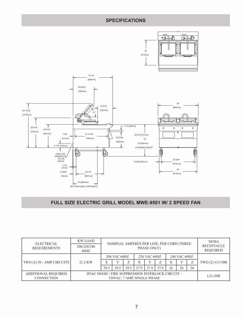
FULL SIZE ELECTRIC GRILL MODEL MWE-9501 W/ 2 SPEED FAN
COOKING HEIGHT
33 [838mm]
30-3/4 [781mm]
28-9/16
[725mm]22-5/16
[567mm]
[959mm]
37-3/4
TO
[965mm]
38
[610mm]
24
BOTTOM CABLE ENTRANCE
23 [584mm]
[667mm]
26-1/42-59/64
[74mm]
32-3/64
[814mm]
31-21/64
[796mm]
1-5/8
[41mm] 15-27/64
[392mm]
1-1/2 [38mm]
1-63/64 [50mm]
36
[914mm]
14-5/16
[363mm]51°
19-29/32
[505mm]
[1076mm]
42-11/32
4-1/16 [103mm]
VENT FAN
INTERFACE
3/4 DIA
[19mm]
11/32
[9mm]
ELECTRICAL REQUIREMENTS
KW LOADNOMINAL AMPERES PER LINE, PER CORD (THREE
PHASE ONLY)
NEMA RECEPTACLE
REQUIRED208/220/240
60HZ
TWO (2) 50 - AMP CIRCUITS 21.2 KW208 VAC 60HZ 220 VAC 60HZ 240 VAC 60HZ
TWO (2) #15-50RX Y Z X Y Z X Y Z29.5 29.5 29.5 27.9 27.9 27.9 26 26 26
ADDITIONAL REQUIRED CONNECTION
HVAC HOOD / FIRE SUPPRESSION INTERLOCK CIRCUIT - 120VAC, 7 AMP, SINGLE PHASE L21-20R
SPECIFICATIONS
SPECIFICATIONS
8
[610mm]
24
20
[508mm]
[392mm]
15-27/64
[567mm]
22-5/16
[725mm]
28-9/16
[796mm]
31-21/64
26-1/4
[667mm][74mm]
2-59/64
[41mm]
1-5/8
14-5/16
[363mm]
37-3/4
[959mm]
1-1/2 [38mm]
30-3/4 [781mm]
33 [838mm]
COOKING HEIGHT
TO
1-63/64 [50mm]14-3/64
[357mm]
18
[457mm]
19-1/4 [489mm]
BOTTOM CABLE ENTRANCE
51°
19-29/32
[505mm]
42-11/32
[1076mm]
4-1/16 [103mm]
11/32 [9mm]
VENT FAN
INTERFACE
3/4 DIA
[19mm]
6-43/64 [169mm]
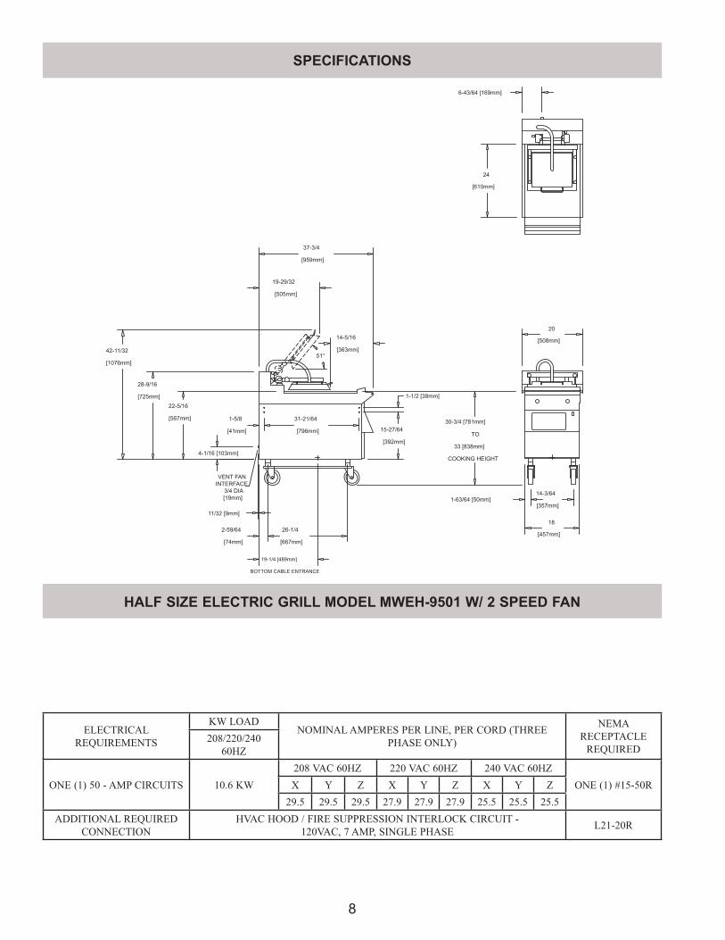
ELECTRICAL REQUIREMENTS
KW LOADNOMINAL AMPERES PER LINE, PER CORD (THREE
PHASE ONLY)
NEMA RECEPTACLE
REQUIRED208/220/240
60HZ
ONE (1) 50 - AMP CIRCUITS 10.6 KW208 VAC 60HZ 220 VAC 60HZ 240 VAC 60HZ
ONE (1) #15-50RX Y Z X Y Z X Y Z29.5 29.5 29.5 27.9 27.9 27.9 25.5 25.5 25.5
ADDITIONAL REQUIRED CONNECTION
HVAC HOOD / FIRE SUPPRESSION INTERLOCK CIRCUIT - 120VAC, 7 AMP, SINGLE PHASE L21-20R
HALF SIZE ELECTRIC GRILL MODEL MWEH-9501 W/ 2 SPEED FAN
SPECIFICATIONS
9
24”(610mm)
38”(965mm)
30 - 3/4” (781mm)TO
33” (838mm)COOKING HEIGHT
32 - 3/64”(814mm)
36”(914mm)
1 - ½” (38mm)
1 - 63/64” (50mm)
15 - 27/64”(392mm)
14 - 5/16”(363mm)
37 - 3/4”(959mm)
19 - 29/32”(505mm)
42 - 11/32”(1076mm)
28 - 9/16”(725mm) 22 - 5/16”
(567mm)
1 - 5/8”(41mm)
31 - 21/64”(796mm)
51
2 - 59/64”(74mm)
23” (584mm)
BOTTOM CABLE ENTRANCE
26 -1/4”(667mm)
ELECTRICAL REQUIREMENTS
KW LOADNOMINAL AMPERES PER LINE, PER CORD (THREE
PHASE ONLY)
NEMA RECEPTACLE
REQUIRED208/220/240
60HZ
TWO (2) 50 - AMP CIRCUITS 18.1 KW208 VAC 60HZ 220 VAC 60HZ 240 VAC 60HZ
TWO (2) #15-50RX Y Z X Y Z X Y Z25.1 25.1 25.1 23.8 23.8 23.8 21.8 21.8 21.8
ADDITIONAL REQUIRED CONNECTION
HVAC HOOD / FIRE SUPPRESSION INTERLOCK CIRCUIT - 120VAC, 7 AMP, SINGLE PHASE L21-20R
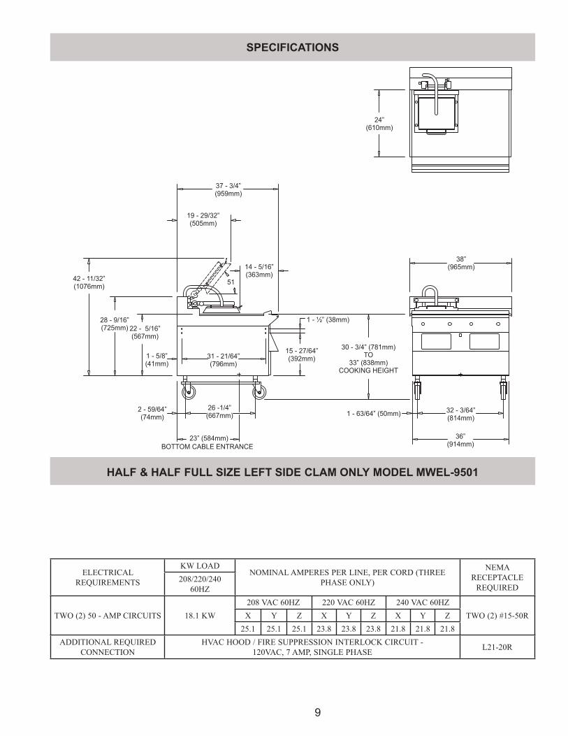
HALF & HALF FULL SIZE LEFT SIDE CLAM ONLY MODEL MWEL-9501
SPECIFICATIONS
10
24”(610mm)
38”(965mm)
32 - 3/64”(814mm)
36”(914mm)
30 - 3/4” (781mm)TO
33” (838mm)COOKING HEIGHT
1 - 63/64” (50mm)
1 - ½” (38mm)
15 - 27/64”(392mm)
37 - 3/4”(959mm)
19 - 29/32”(505mm)
14 - 5/16”(363mm)
5142 - 11/32”(1076mm)
28 - 9/16”(725mm)
22 - 5/16”(567mm)
1 - 5/8”(41mm)
31 - 21/64”(796mm)
2 - 59/64”(74mm)
26 -1/4”(667mm)
23” (584mm)
BOTTOM CABLE ENTRANCE
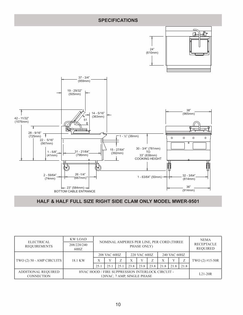
HALF & HALF FULL SIZE RIGHT SIDE CLAM ONLY MODEL MWER-9501
ELECTRICAL REQUIREMENTS
KW LOADNOMINAL AMPERES PER LINE, PER CORD (THREE
PHASE ONLY)
NEMA RECEPTACLE
REQUIRED208/220/240
60HZ
TWO (2) 50 - AMP CIRCUITS 18.1 KW208 VAC 60HZ 220 VAC 60HZ 240 VAC 60HZ
TWO (2) #15-50RX Y Z X Y Z X Y Z25.1 25.1 25.1 23.8 23.8 23.8 21.8 21.8 21.8
ADDITIONAL REQUIRED CONNECTION
HVAC HOOD / FIRE SUPPRESSION INTERLOCK CIRCUIT - 120VAC, 7 AMP, SINGLE PHASE L21-20R
SPECIFICATIONS
SPECIFICATIONS
11
24”(610mm)
38”(965mm)
36”(914mm)
32-3/64”(814mm)
30-3/4” (781mm)TO
33” (838mm)COOKING HEIGHT
1-63/64”(50mm)
15-27/64”(392mm)
1-1/2” (38mm)
37-3/4”(959mm)
31-21/64”(796mm)
28-9/16”(725mm)
20-21/64”(516mm)
1-5/8”(41mm)
2-59/6”(74mm) 26-1/4”
(667mm)
23”(584mm)BOTTOM CABLE ENTRANCE
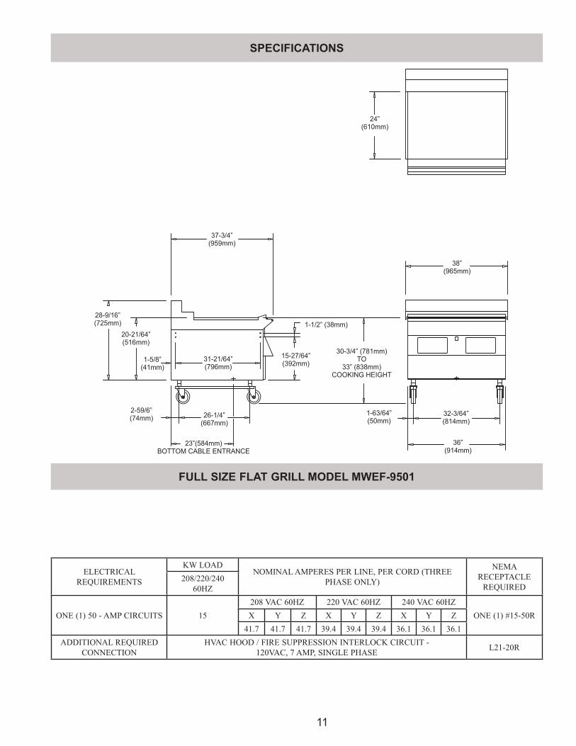
FULL SIZE FLAT GRILL MODEL MWEF-9501
ELECTRICAL REQUIREMENTS
KW LOADNOMINAL AMPERES PER LINE, PER CORD (THREE
PHASE ONLY)
NEMA RECEPTACLE
REQUIRED208/220/240
60HZ
ONE (1) 50 - AMP CIRCUITS 15208 VAC 60HZ 220 VAC 60HZ 240 VAC 60HZ
ONE (1) #15-50RX Y Z X Y Z X Y Z41.7 41.7 41.7 39.4 39.4 39.4 36.1 36.1 36.1
ADDITIONAL REQUIRED CONNECTION
HVAC HOOD / FIRE SUPPRESSION INTERLOCK CIRCUIT - 120VAC, 7 AMP, SINGLE PHASE L21-20R
SPECIFICATIONS
12
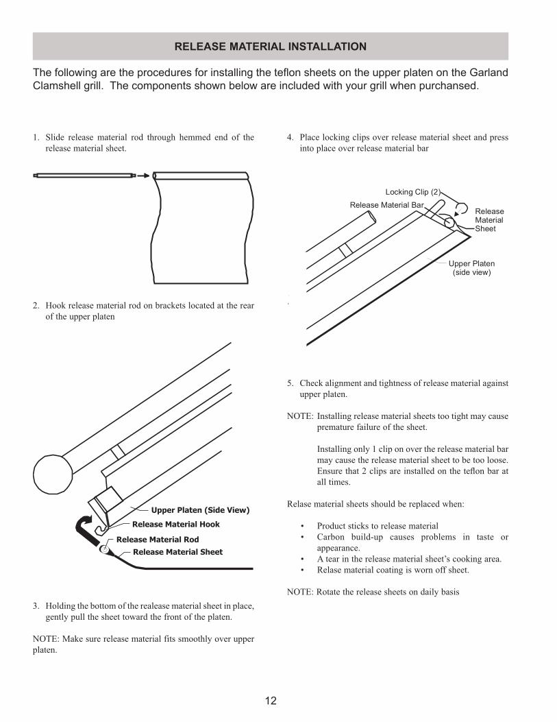
The following are the procedures for installing the teflon sheets on the upper platen on the Garland Clamshell grill. The components shown below are included with your grill when purchansed.
1. Slide release material rod through hemmed end of the release material sheet.
2. Hook release material rod on brackets located at the rear of the upper platen
Upper Platen (Side View)
Release Material Hook
Release Material Rod
Release Material Sheet
3. Holding the bottom of the realease material sheet in place, gently pull the sheet toward the front of the platen.
NOTE: Make sure release material fits smoothly over upper platen.
4. Place locking clips over release material sheet and press into place over release material bar
5. Check alignment and tightness of release material against upper platen.
NOTE: Installing release material sheets too tight may cause premature failure of the sheet.
Installing only 1 clip on over the release material bar may cause the release material sheet to be too loose. Ensure that 2 clips are installed on the tefl on bar at all times.
Relase material sheets should be replaced when:
• Product sticks to release material • Carbon build-up causes problems in taste or
appearance. • A tear in the release material sheet’s cooking area. • Relase material coating is worn off sheet.
NOTE: Rotate the release sheets on daily basis
RELEASE MATERIAL INSTALLATION
13
Insert this end first
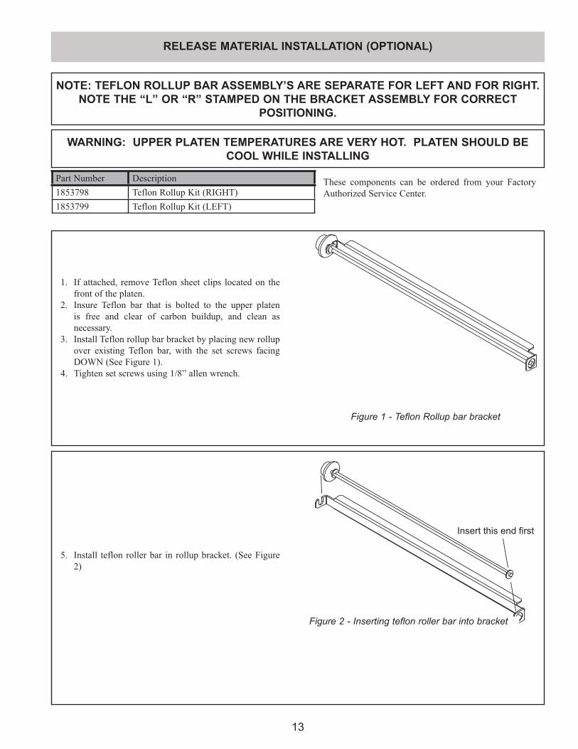
NOTE: TEFLON ROLLUP BAR ASSEMBLY’S ARE SEPARATE FOR LEFT AND FOR RIGHT. NOTE THE “L” OR “R” STAMPED ON THE BRACKET ASSEMBLY FOR CORRECT
POSITIONING.
WARNING: UPPER PLATEN TEMPERATURES ARE VERY HOT. PLATEN SHOULD BE COOL WHILE INSTALLING
Figure 1 - Teflon Rollup bar bracket
1. If attached, remove Teflon sheet clips located on the front of the platen.
2. Insure Teflon bar that is bolted to the upper platen is free and clear of carbon buildup, and clean as necessary.
3. Install Teflon rollup bar bracket by placing new rollup over existing Teflon bar, with the set screws facing DOWN (See Figure 1).
4. Tighten set screws using 1/8” allen wrench.
5. Install teflon roller bar in rollup bracket. (See Figure 2)
Figure 2 - Inserting teflon roller bar into bracket
RELEASE MATERIAL INSTALLATION (OPTIONAL)
Part Number Description1853798 Teflon Rollup Kit (RIGHT)1853799 Teflon Rollup Kit (LEFT)
These components can be ordered from your Factory Authorized Service Center.
14
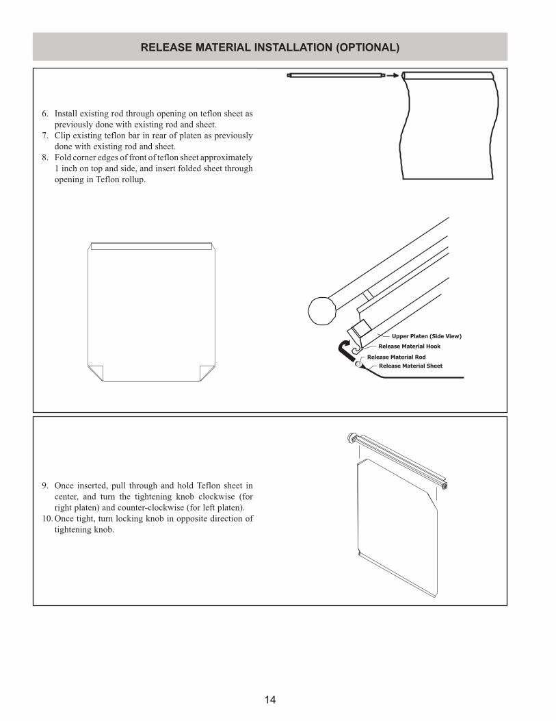
6. Install existing rod through opening on teflon sheet as previously done with existing rod and sheet.
7. Clip existing teflon bar in rear of platen as previously done with existing rod and sheet.
8. Fold corner edges of front of teflon sheet approximately 1 inch on top and side, and insert folded sheet through opening in Teflon rollup.
Upper Platen (Side View)
Release Material Hook
Release Material Rod
Release Material Sheet
9. Once inserted, pull through and hold Teflon sheet in center, and turn the tightening knob clockwise (for right platen) and counter-clockwise (for left platen).
10. Once tight, turn locking knob in opposite direction of tightening knob.
RELEASE MATERIAL INSTALLATION (OPTIONAL)
15
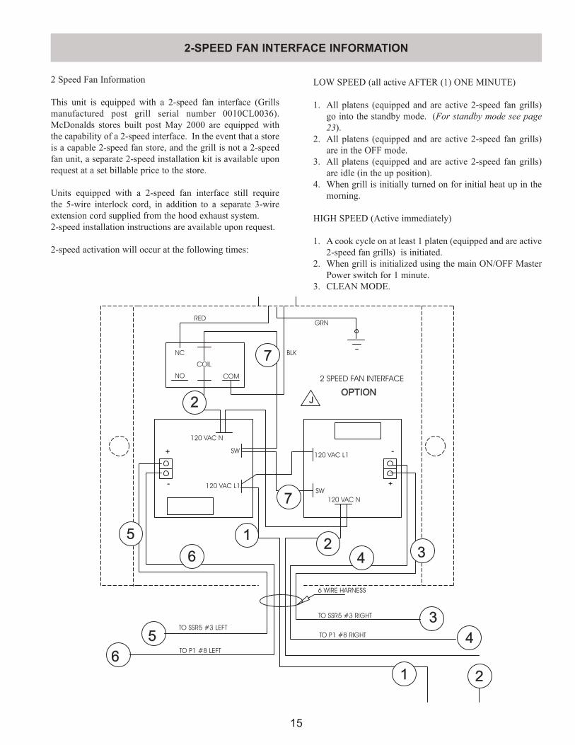
2 Speed Fan Information
This unit is equipped with a 2-speed fan interface (Grills manufactured post grill serial number 0010CL0036). McDonalds stores built post May 2000 are equipped with the capability of a 2-speed interface. In the event that a store is a capable 2-speed fan store, and the grill is not a 2-speed fan unit, a separate 2-speed installation kit is available upon request at a set billable price to the store.
Units equipped with a 2-speed fan interface still require the 5-wire interlock cord, in addition to a separate 3-wire extension cord supplied from the hood exhaust system.2-speed installation instructions are available upon request.
2-speed activation will occur at the following times:
LOW SPEED (all active AFTER (1) ONE MINUTE)
1. All platens (equipped and are active 2-speed fan grills) go into the standby mode. (For standby mode see page 23).
2. All platens (equipped and are active 2-speed fan grills) are in the OFF mode.
3. All platens (equipped and are active 2-speed fan grills) are idle (in the up position).
4. When grill is initially turned on for initial heat up in the morning.
HIGH SPEED (Active immediately)
1. A cook cycle on at least 1 platen (equipped and are active 2-speed fan grills) is initiated.
2. When grill is initialized using the main ON/OFF Master Power switch for 1 minute.
3. CLEAN MODE.
2-SPEED FAN INTERFACE INFORMATION
5
6
5
6
-
+
2
1
1
3
24 3
2
4
7
7
J
+
-
OPTION
GRN
120 VAC L1
RED
BLK
COM
COIL
NC
NO 2 SPEED FAN INTERFACE
SW
120 VAC N
120 VAC N
SW
120 VAC L1
TO SSR5 #3 LEFT
TO SSR5 #3 RIGHT
TO P1 #8 RIGHT
TO P1 #8 LEFT
6 WIRE HARNESS
16
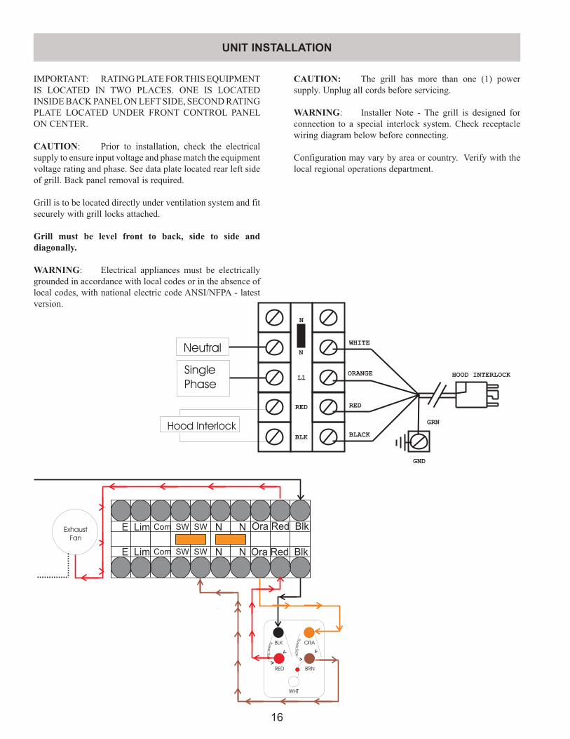
IMPORTANT: RATING PLATE FOR THIS EQUIPMENT IS LOCATED IN TWO PLACES. ONE IS LOCATED INSIDE BACK PANEL ON LEFT SIDE, SECOND RATING PLATE LOCATED UNDER FRONT CONTROL PANEL ON CENTER.
CAUTION: Prior to installation, check the electrical supply to ensure input voltage and phase match the equipment voltage rating and phase. See data plate located rear left side of grill. Back panel removal is required.
Grill is to be located directly under ventilation system and fit securely with grill locks attached.
Grill must be level front to back, side to side and diagonally.
WARNING: Electrical appliances must be electrically grounded in accordance with local codes or in the absence of local codes, with national electric code ANSI/NFPA - latest version.
UNIT INSTALLATION
CAUTION: The grill has more than one (1) power supply. Unplug all cords before servicing.
WARNING: Installer Note - The grill is designed for connection to a special interlock system. Check receptacle wiring diagram below before connecting.
Configuration may vary by area or country. Verify with the local regional operations department.
ORABLK
RED BRN
WHT
Ora Red BlkE Lim Com SW SW N N
Ora Red BlkE Lim Com SW SW N N
Pow
erFlo
w
Pow
erFlo
w
Exhaust
Fan
ORANGE HOOD INTERLOCK
RED
BLACK
WHITE
BLK
RED
N
L1
GND
GRN
N
Neutral
Single
Phase
Hood Interlock
17
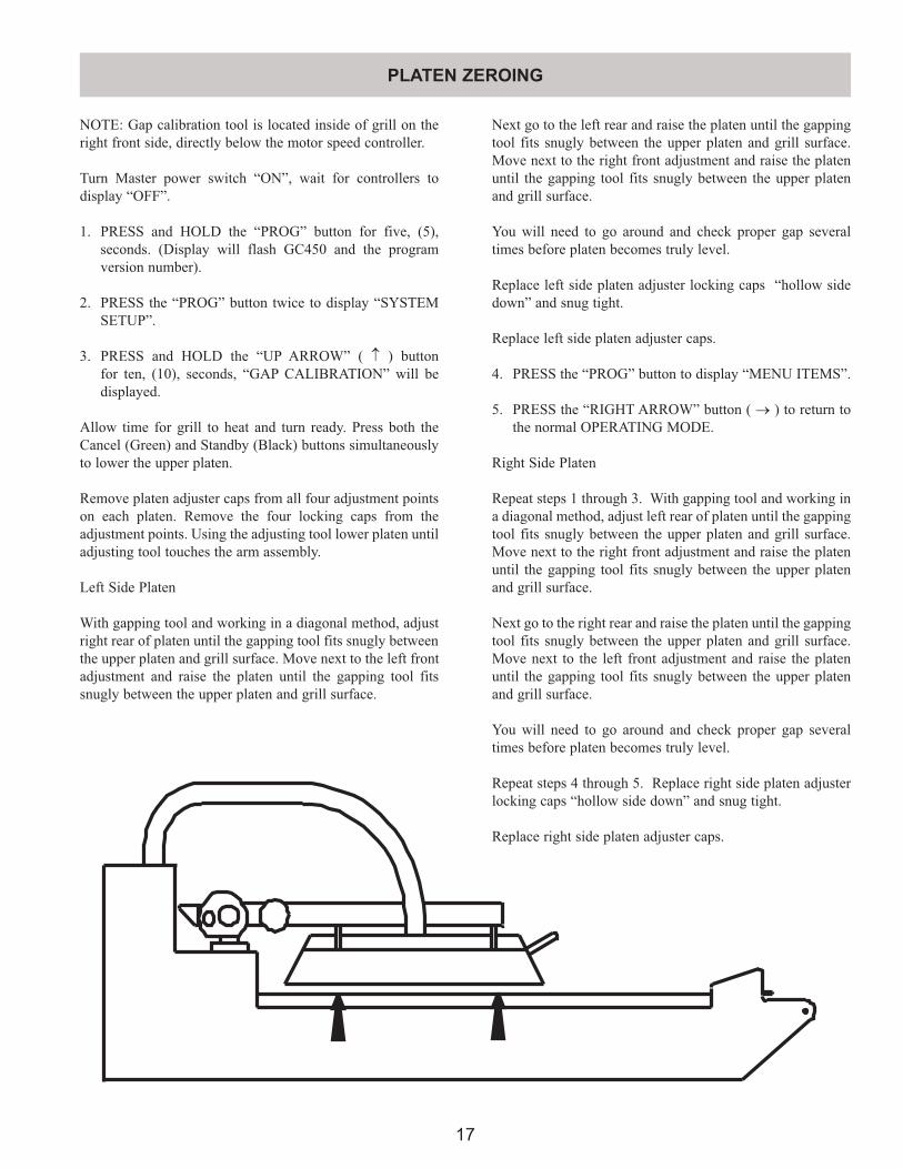
NOTE: Gap calibration tool is located inside of grill on the right front side, directly below the motor speed controller.
Turn Master power switch “ON”, wait for controllers to display “OFF”.
1. PRESS and HOLD the “PROG” button for five, (5), seconds. (Display will flash GC450 and the program version number).
2. PRESS the “PROG” button twice to display “SYSTEM SETUP”.
3. PRESS and HOLD the “UP ARROW” ( ↑ ) button for ten, (10), seconds, “GAP CALIBRATION” will be displayed.
Allow time for grill to heat and turn ready. Press both the Cancel (Green) and Standby (Black) buttons simultaneously to lower the upper platen.
Remove platen adjuster caps from all four adjustment points on each platen. Remove the four locking caps from the adjustment points. Using the adjusting tool lower platen until adjusting tool touches the arm assembly.
Left Side Platen
With gapping tool and working in a diagonal method, adjust right rear of platen until the gapping tool fits snugly between the upper platen and grill surface. Move next to the left front adjustment and raise the platen until the gapping tool fits snugly between the upper platen and grill surface.
Next go to the left rear and raise the platen until the gapping tool fits snugly between the upper platen and grill surface. Move next to the right front adjustment and raise the platen until the gapping tool fits snugly between the upper platen and grill surface.
You will need to go around and check proper gap several times before platen becomes truly level.
Replace left side platen adjuster locking caps “hollow side down” and snug tight.
Replace left side platen adjuster caps.
4. PRESS the “PROG” button to display “MENU ITEMS”.
5. PRESS the “RIGHT ARROW” button ( → ) to return to the normal OPERATING MODE.
Right Side Platen
Repeat steps 1 through 3. With gapping tool and working in a diagonal method, adjust left rear of platen until the gapping tool fits snugly between the upper platen and grill surface. Move next to the right front adjustment and raise the platen until the gapping tool fits snugly between the upper platen and grill surface.
Next go to the right rear and raise the platen until the gapping tool fits snugly between the upper platen and grill surface. Move next to the left front adjustment and raise the platen until the gapping tool fits snugly between the upper platen and grill surface.
You will need to go around and check proper gap several times before platen becomes truly level.
Repeat steps 4 through 5. Replace right side platen adjuster locking caps “hollow side down” and snug tight.
Replace right side platen adjuster caps.
PLATEN ZEROING
18
PLATEN ZEROING
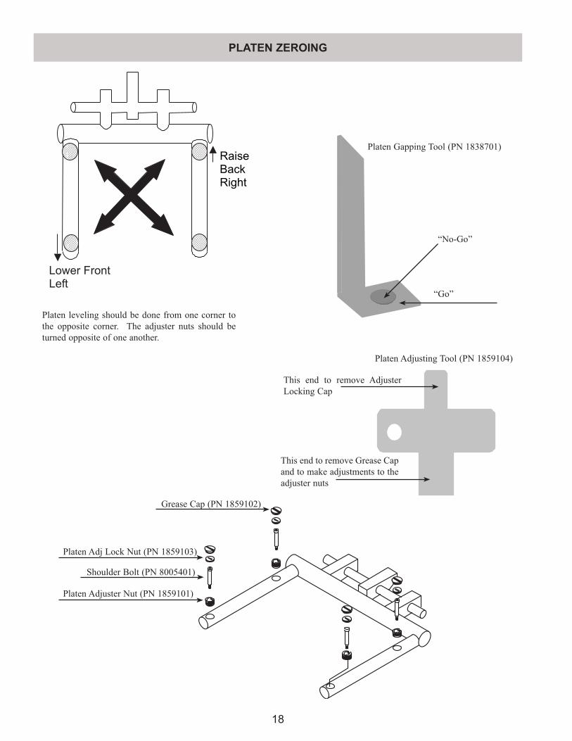
RaiseBackRight
Lower FrontLeft
“No-Go”
“Go”
This end to remove Adjuster Locking Cap
This end to remove Grease Cap and to make adjustments to the adjuster nuts
Platen leveling should be done from one corner to the opposite corner. The adjuster nuts should be turned opposite of one another.
Platen Adj Lock Nut (PN 1859103)
Shoulder Bolt (PN 8005401)
Platen Adjuster Nut (PN 1859101)
Grease Cap (PN 1859102)
Platen Adjusting Tool (PN 1859104)
Platen Gapping Tool (PN 1838701)
19
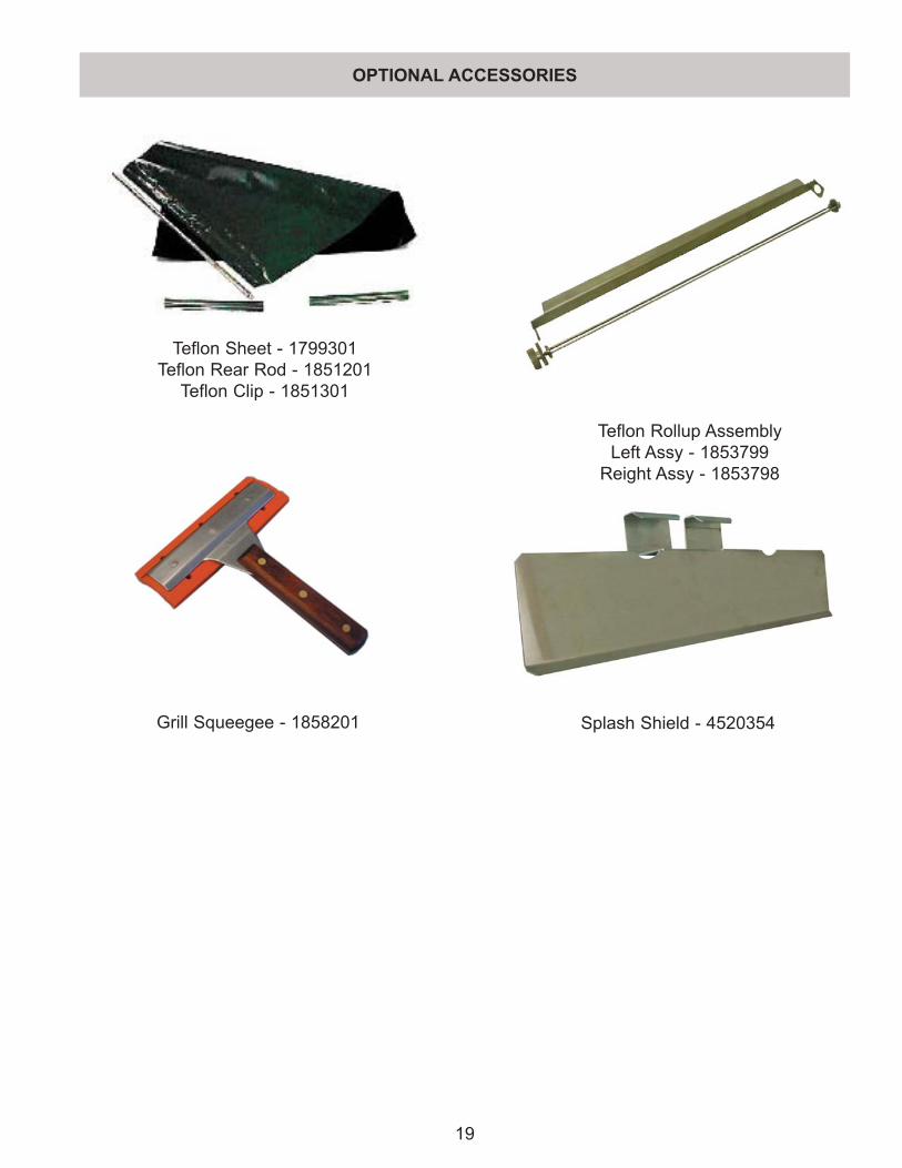
Teflon Sheet - 1799301Teflon Rear Rod - 1851201
Teflon Clip - 1851301
Teflon Rollup AssemblyLeft Assy - 1853799
Reight Assy - 1853798
Grill Squeegee - 1858201 Splash Shield - 4520354
OPTIONAL ACCESSORIES
20
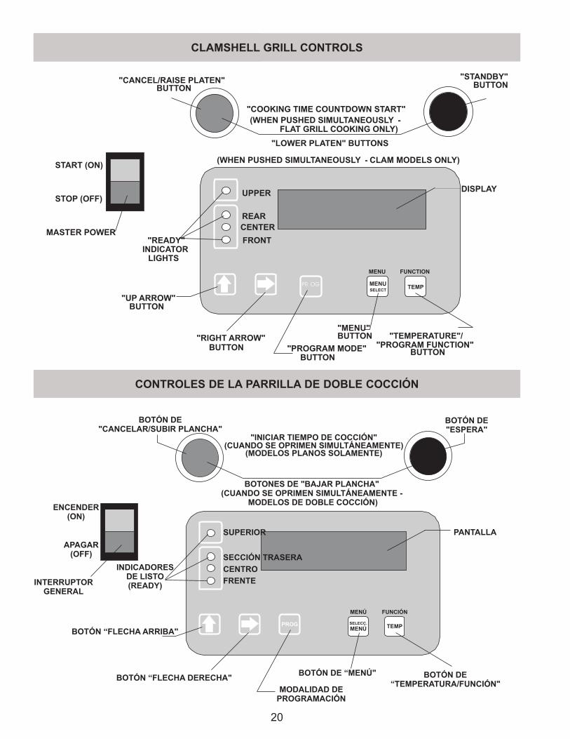
TEMP
MENU FUNCTION
MENUSELECT
PR OG
DISPLAY
"LOWER PLATEN" BUTTONS
"READY"INDICATOR
LIGHTS
"MENU"BUTTON "TEMPERATURE"/
"PROGRAM FUNCTION"BUTTON"PROGRAM MODE"
BUTTON
"RIGHT ARROW"BUTTON
"UP ARROW"BUTTON
(WHEN PUSHED SIMULTANEOUSLY - CLAM MODELS ONLY)
"CANCEL/RAISE PLATEN"BUTTON
"STANDBY"BUTTON
UPPER
REARCENTER
FRONT
"COOKING TIME COUNTDOWN START"(WHEN PUSHED SIMULTANEOUSLY -
FLAT GRILL COOKING ONLY)
MASTER POWER
START (ON)
STOP (OFF)
CLAMSHELL GRILL CONTROLS
TEMP
MENÚ FUNCIÓN
SELECC.
MENÚ
PANTALLA
INTERRUPTORGENERAL
BOTONES DE "BAJAR PLANCHA"(CUANDO SE OPRIMEN SIMULTÁNEAMENTE -
MODELOS DE DOBLE COCCIÓN)
DE LISTOINDICADORES
(READY)
BOTÓN DE “MENÚ" BOTÓN DE“TEMPERATURA/FUNCIÓN"
MODALIDAD DEPROGRAMACIÓN
BOTÓN “FLECHA DERECHA"
BOTÓN “FLECHA ARRIBA"
BOTÓN DE"CANCELAR/SUBIR PLANCHA"
BOTÓN DE"ESPERA"
ENCENDER(ON)
APAGAR(OFF)
SUPERIOR
SECCI TRASERAÓN
CENTRO
FRENTE
"INICIAR TIEMPO DE COCCIÓN"(CUANDO SE OPRIMEN SIMULTÁNEAMENTE)
(MODELOS PLANOS SOLAMENTE)
PROG
CONTROLES DE LA PARRILLA DE DOBLE COCCIÓN
21
The Master Power (Pushbutton (ON / OFF)
Program Mode Button - Two Functions
Indicator Lights
Right Arrow Button - Two Functions
Up Arrow Button - Two Functions
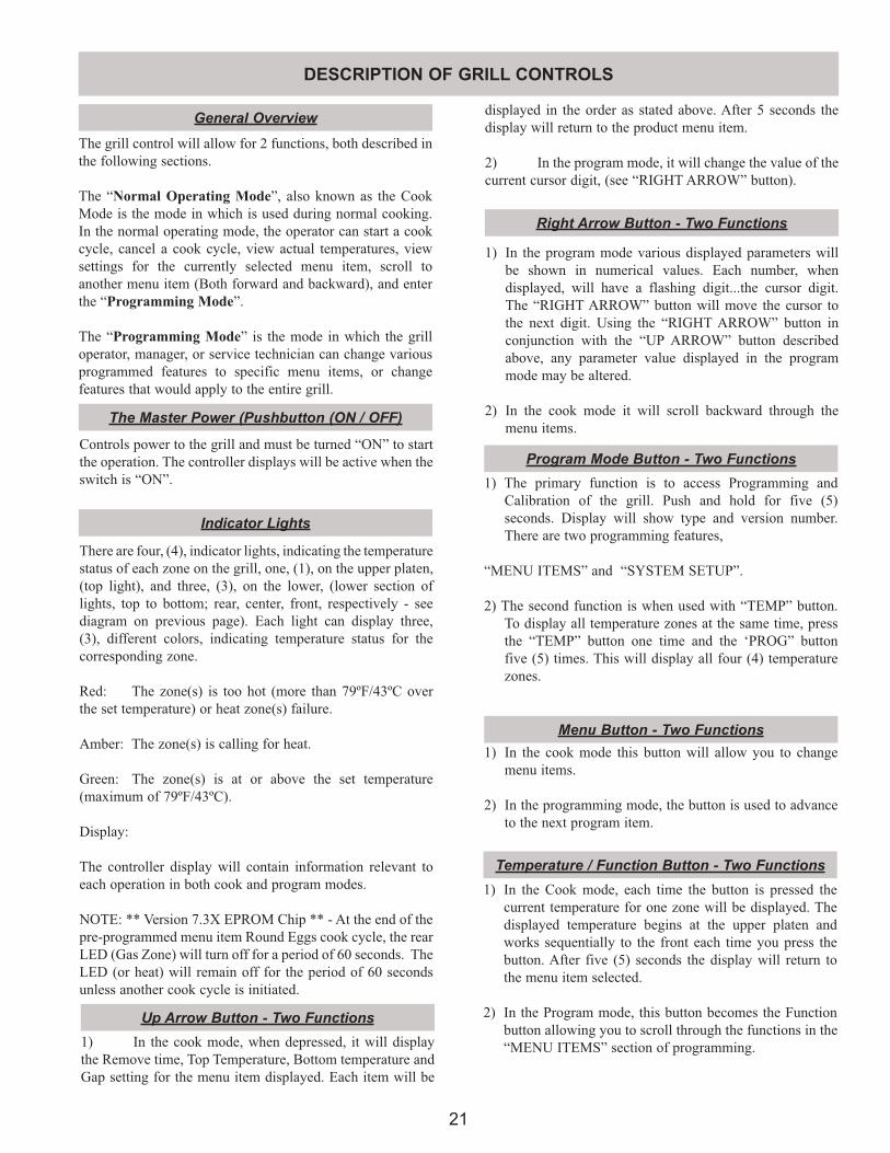
Controls power to the grill and must be turned “ON” to start the operation. The controller displays will be active when the switch is “ON”.
There are four, (4), indicator lights, indicating the temperature status of each zone on the grill, one, (1), on the upper platen, (top light), and three, (3), on the lower, (lower section of lights, top to bottom; rear, center, front, respectively - see diagram on previous page). Each light can display three, (3), different colors, indicating temperature status for the corresponding zone.
Red: The zone(s) is too hot (more than 79ºF/43ºC over the set temperature) or heat zone(s) failure.
Amber: The zone(s) is calling for heat.
Green: The zone(s) is at or above the set temperature (maximum of 79ºF/43ºC).
Display:
The controller display will contain information relevant to each operation in both cook and program modes.
NOTE: ** Version 7.3X EPROM Chip ** - At the end of the pre-programmed menu item Round Eggs cook cycle, the rear LED (Gas Zone) will turn off for a period of 60 seconds. The LED (or heat) will remain off for the period of 60 seconds unless another cook cycle is initiated.
1) In the cook mode, when depressed, it will display the Remove time, Top Temperature, Bottom temperature and Gap setting for the menu item displayed. Each item will be
1) In the program mode various displayed parameters will be shown in numerical values. Each number, when displayed, will have a flashing digit...the cursor digit. The “RIGHT ARROW” button will move the cursor to the next digit. Using the “RIGHT ARROW” button in conjunction with the “UP ARROW” button described above, any parameter value displayed in the program mode may be altered.
2) In the cook mode it will scroll backward through the menu items.
1) The primary function is to access Programming and Calibration of the grill. Push and hold for five (5) seconds. Display will show type and version number. There are two programming features,
“MENU ITEMS” and “SYSTEM SETUP”.
2) The second function is when used with “TEMP” button. To display all temperature zones at the same time, press the “TEMP” button one time and the ‘PROG” button five (5) times. This will display all four (4) temperature zones.
The grill control will allow for 2 functions, both described in the following sections.
The “Normal Operating Mode”, also known as the Cook Mode is the mode in which is used during normal cooking. In the normal operating mode, the operator can start a cook cycle, cancel a cook cycle, view actual temperatures, view settings for the currently selected menu item, scroll to another menu item (Both forward and backward), and enter the “Programming Mode”.
The “Programming Mode” is the mode in which the grill operator, manager, or service technician can change various programmed features to specific menu items, or change features that would apply to the entire grill.
General Overview
DESCRIPTION OF GRILL CONTROLS
Menu Button - Two Functions1) In the cook mode this button will allow you to change
menu items.
2) In the programming mode, the button is used to advance to the next program item.
Temperature / Function Button - Two Functions1) In the Cook mode, each time the button is pressed the
current temperature for one zone will be displayed. The displayed temperature begins at the upper platen and works sequentially to the front each time you press the button. After five (5) seconds the display will return to the menu item selected.
2) In the Program mode, this button becomes the Function button allowing you to scroll through the functions in the “MENU ITEMS” section of programming.
displayed in the order as stated above. After 5 seconds the display will return to the product menu item.
2) In the program mode, it will change the value of the current cursor digit, (see “RIGHT ARROW” button).
22
To Cook in Clam Grill Mode:
NOTE - TO STOP THE GRILL AT ANY TIME, TURN THE MASTER POWER SWITCH OFF
To Cook in Flat Grill Mode:
Cancel / Raise Button - Green
NORMAL OPERATING MODES
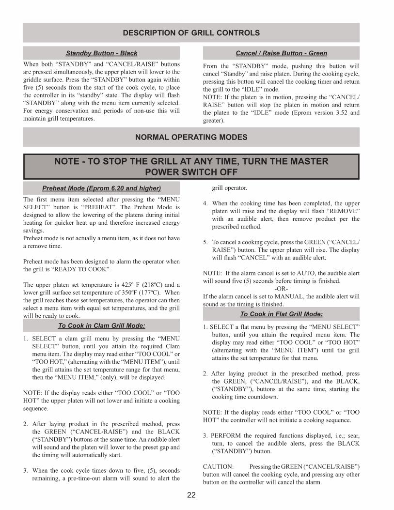
1. SELECT a clam grill menu by pressing the “MENU SELECT” button, until you attain the required Clam menu item. The display may read either “TOO COOL” or “TOO HOT,” (alternating with the “MENU ITEM”), until the grill attains the set temperature range for that menu, then the “MENU ITEM,” (only), will be displayed.
NOTE: If the display reads either “TOO COOL” or “TOO HOT” the upper platen will not lower and initiate a cooking sequence.
2. After laying product in the prescribed method, press the GREEN (“CANCEL/RAISE”) and the BLACK (“STANDBY”) buttons at the same time. An audible alert will sound and the platen will lower to the preset gap and the timing will automatically start.
3. When the cook cycle times down to five, (5), seconds remaining, a pre-time-out alarm will sound to alert the
1. SELECT a flat menu by pressing the “MENU SELECT” button, until you attain the required menu item. The display may read either “TOO COOL” or “TOO HOT” (alternating with the “MENU ITEM”) until the grill attains the set temperature for that menu.
2. After laying product in the prescribed method, press the GREEN, (“CANCEL/RAISE”), and the BLACK, (“STANDBY”), buttons at the same time, starting the cooking time countdown.
NOTE: If the display reads either “TOO COOL” or “TOO HOT” the controller will not initiate a cooking sequence.
3. PERFORM the required functions displayed, i.e.; sear, turn, to cancel the audible alerts, press the BLACK (“STANDBY”) button.
CAUTION: Pressing the GREEN (“CANCEL/RAISE”) button will cancel the cooking cycle, and pressing any other button on the controller will cancel the alarm.
Preheat Mode (Eprom 6.20 and higher)The first menu item selected after pressing the “MENU SELECT” button is “PREHEAT”. The Preheat Mode is designed to allow the lowering of the platens during initial heating for quicker heat up and therefore increased energy savings.Preheat mode is not actually a menu item, as it does not have a remove time.
Preheat mode has been designed to alarm the operator when the grill is “READY TO COOK”. The upper platen set temperature is 425º F (218ºC) and a lower grill surface set temperature of 350ºF (177ºC). When the grill reaches these set temperatures, the operator can then select a menu item with equal set temperatures, and the grill will be ready to cook.
From the “STANDBY” mode, pushing this button will cancel “Standby” and raise platen. During the cooking cycle, pressing this button will cancel the cooking timer and return the grill to the “IDLE” mode.NOTE: If the platen is in motion, pressing the “CANCEL/RAISE” button will stop the platen in motion and return the platen to the “IDLE” mode (Eprom version 3.52 and greater).
grill operator.
4. When the cooking time has been completed, the upper platen will raise and the display will flash “REMOVE” with an audible alert, then remove product per the prescribed method.
5. To cancel a cooking cycle, press the GREEN (“CANCEL/RAISE”) button. The upper platen will rise. The display will flash “CANCEL” with an audible alert.
NOTE: If the alarm cancel is set to AUTO, the audible alert will sound five (5) seconds before timing is finished.
-OR-If the alarm cancel is set to MANUAL, the audible alert will sound as the timing is finished.
Standby Button - BlackWhen both “STANDBY” and “CANCEL/RAISE” buttons are pressed simultaneously, the upper platen will lower to the griddle surface. Press the “STANDBY” button again within five (5) seconds from the start of the cook cycle, to place the controller in its “standby” state. The display will flash “STANDBY” along with the menu item currently selected. For energy conservation and periods of non-use this will maintain grill temperatures.
DESCRIPTION OF GRILL CONTROLS
23
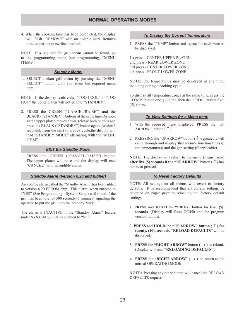
Standby Mode:
EXIT the Standby Mode:
1. SELECT a clam grill menu by pressing the “MENU SELECT” button, until you attain the required menu item.
NOTE: If the display reads either “TOO COOL” or “TOO HOT” the upper platen will not go into “STANDBY”.
2. PRESS the GREEN (“CANCEL/RAISE”) and the BLACK (“STANDBY”) buttons at the same time. As soon as the upper platen moves down, release both buttons and press the BLACK (“STANDBY”) button again, (within 5 seconds), from the start of a cook cycle,the display will read “STANDBY MODE” alternating with the “MENU ITEM”.
1. PRESS the GREEN (“CANCEL/RAISE”) button. The upper platen will raise and the display will read “CANCEL” with an audible alarm.
4. When the cooking time has been completed, the display will flash “REMOVE” with an audible alert. Remove product per the prescribed method.
NOTE: If a required flat grill menu cannot be found, go to the programming mode (see programming, “MENU ITEMS”.
1. PRESS the “TEMP” button and repeat for each zone to be displayed.
1st press - CENTER UPPER PLATEN2nd press - REAR LOWER ZONE3rd press - CENTER LOWER ZONE4th press - FRONT LOWER ZONE
NOTE: The temperatures may be displayed at any time, including during a cooking cycle. To display all temperature zones at the same time, press the “TEMP” button one, (1), time, then the “PROG” button five, (5), times.
To View Settings for a Menu Item:
To Display the Current Temperature
Standby Alarm (Version 6.20 and higher)
An audible alarm called the “Standby Alarm” has been added to version 6.20 EPROM chip. This alarm, when enabled to “YES” (See Programming - System Setup) will sound if the grill has been idle for 300 seconds (5 minutes) signaling the operator to put the grill into the Standby Mode.
The alarm is INACTIVE if the “Standby Alarm” feature under SYSTEM SETUP is enabled to “NO”.
1. With the required menu displayed, PRESS the “UP ARROW “ button ( ↑ ).
2. PRESSING the "UP ARROW" button ( ↑ ) repeatedly will cycle through and display that menu’s function time(s), set temperature(s) and the gap setting (if applicable).
NOTE: The display will return to the menu (menu name) after five (5) seconds if the “UP ARROW” button ( ↑ ) has not been pressed.
To Reset Factory Defaults
NOTE: All settings on all menus will revert to factory defaults. It is recommended that all current settings be recorded on paper prior to reloading the factory default settings.
1. PRESS and HOLD the “PROG” button for five, (5), seconds. (Display will flash GC450 and the program version number.
2. PRESS and HOLD the “UP ARROW” button ( ↑ ) for twenty, (10), seconds, “RELOAD DEFAULTS” will be displayed.
3. PRESS the “RIGHT ARROW” button ( → ) to reload. (Display will read “RELOADING DEFAULTS”).
4. PRESS the “RIGHT ARROW” ( → ) to return to the normal OPERATING MODE.
NOTE: Pressing any other button will cancel the RELOAD DEFAULTS request.
NORMAL OPERATING MODES
24
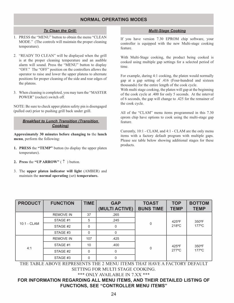
If you have version 7.30 EPROM chip software, your controller is equipped with the new Multi-stage cooking feature.
With Multi-Stage cooking, the product being cooked is cooked using multiple gap settings for a selected period of time.
For example, during 4:1 cooking, the platen would normally gap at a gap setting of .416 (Four-hundred and sixteen thousands) for the entire length of the cook cycle.With multi stage cooking, the platen will gap at the beginning of the cook cycle at .400 for only 5 seconds. At the interval of 6 seconds, the gap will change to .425 for the remainer of the cook cycle.
All of the “CLAM” menu items programmed in this 7.30 eprom chip have options to cook using the multi-stage gap feature.
Currently, 10:1 - CLAM, and 4:1 - CLAM are the only menu items with a factory default program with multiple gaps. Please see table below showing additional stages for these products.
Multi-Stage Cooking1. PRESS the “MENU” button to obtain the menu “CLEAN
MODE.” (The controls will maintain the proper cleaning temperature).
2. “READY TO CLEAN” will be displayed when the grill is at the proper cleaning temperature and an audible alarm will sound. Press the “MENU” button to display “OFF.” The “OFF” position on the controllers allows the operator to raise and lower the upper platens to alternate positions for proper cleaning of the side and rear edges of the platens.
3. When cleaning is completed, you may turn the “MASTER POWER” (rocker) switch off.
NOTE: Be sure to check upper platen safety pin is disengaged (pulled out) prior to pushing grill back under grill.
To Clean the Grill:
Breakfast to Lunch Transition (Transition Cooking)
Approximately 30 minutes before changing to the lunch menu, perform the following:
1. PRESS the “TEMP” button (to display the upper platen temperature).
2. Press the “UP ARROW” ( ↑ ) button.
3. The upper platen indicator will light (AMBER) and maintain the normal operating (set) temperature.
PRODUCT FUNCTION TIME GAP(MULTI ACTIVE)
TOAST BUNS TIME
TOP TEMP
BOTTOM TEMP
10:1 - CLAM
REMOVE IN 37 .265
0 425ºF218ºC
350ºF177ºC
STAGE #1 5 .245
STAGE #2 0 0
STAGE #3 0 0
4:1
REMOVE IN 107 .425
0 425ºF277ºC
350ºF177ºC
STAGE #1 10 .400
STAGE #2 0 0
STAGE #3 0 0
THE TABLE ABOVE REPRESENTS THE 2 MENU ITEMS THAT HAVE A FACTORY DEFAULT SETTING FOR MULTI STAGE COOKING.
*** ONLY AVAILABLE IN 7.XX ***FOR INFORMATION REGARDING ALL MENU ITEMS, AND THEIR DETAILED LISTING OF
FUNCTIONS, SEE “CONTROLLER MENU ITEMS”
NORMAL OPERATING MODES
25
PROG
VERSION X.XX
1X 2X
PROG PROGMENU ITEMS SYSTEM SETUP
MENU
MENU
SELECT
MENU
TEMP
FUNCTION
SELECT MENU ITEM
DISPLAY TEMP(Fahrenheit/Celcius)
ALARM VOLUME
PROBE CALIBRATIONTEMP
FUNCTION
REMOVE IN...REMOVE IN ALARM(AUTO / MANUAL)
SET TEMPERATURE (UPPER PLATEN)SET TEMPERATURE (GRILL SURFACE)
TOP TEMP.
BACK TEMP.
MIDDLE TEMP.
FRONT TEMP.
PRESS & HOLD(5 Seconds)
TOAST BUNS IN...
TOAST BUNS IN ALARM(AUTO / MANUAL)
TURN IN...TURN IN ALARM(AUTO / MANUAL)
SEAR IN...SEAR IN ALARM(AUTO / MANUAL)
STIR IN...STIR IN ALARM(AUTO / MANUAL)
FLAT MENU ITEMS ONLY
CLAM MENU
ITEMS
MENU
SELECT
SELECT SETTING
STANDBY ALERT
GAP VERIFICATION
MULTI GAP (YES / NO)
1X
2X
3X
4X
5X
6X
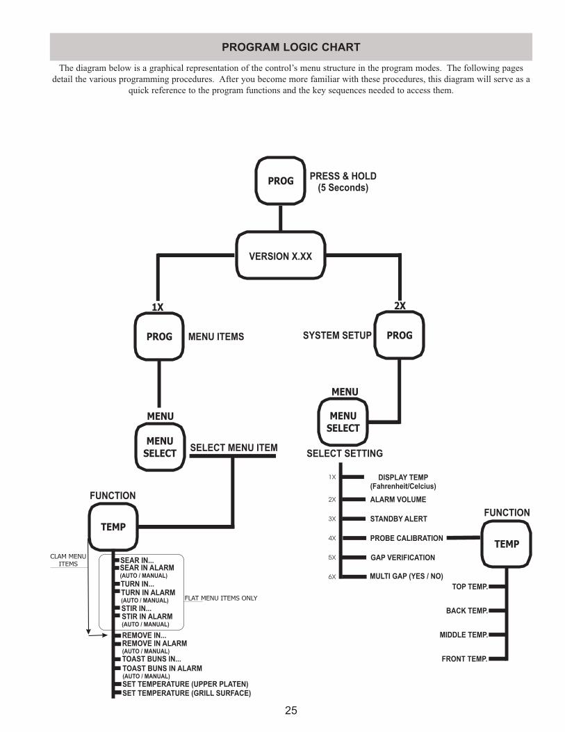
The diagram below is a graphical representation of the control’s menu structure in the program modes. The following pages detail the various programming procedures. After you become more familiar with these procedures, this diagram will serve as a
quick reference to the program functions and the key sequences needed to access them.
PROGRAM LOGIC CHART
26
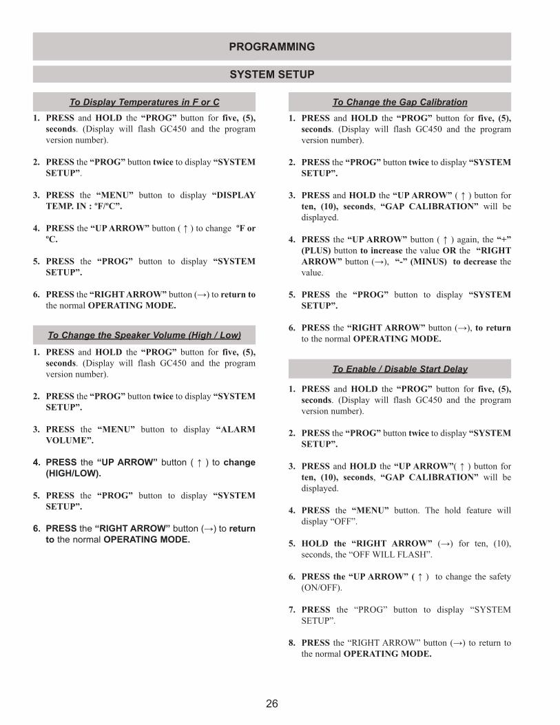
1. PRESS and HOLD the “PROG” button for five, (5), seconds. (Display will flash GC450 and the program version number).
2. PRESS the “PROG” button twice to display “SYSTEM SETUP”.
3. PRESS the “MENU” button to display “DISPLAY TEMP. IN : ºF/ºC”.
4. PRESS the “UP ARROW” button ( ↑ ) to change ºF or ºC.
5. PRESS the “PROG” button to display “SYSTEM SETUP”.
6. PRESS the “RIGHT ARROW” button (→) to return to the normal OPERATING MODE.
1. PRESS and HOLD the “PROG” button for five, (5), seconds. (Display will flash GC450 and the program version number).
2. PRESS the “PROG” button twice to display “SYSTEM SETUP”.
3. PRESS and HOLD the “UP ARROW” ( ↑ ) button for ten, (10), seconds, “GAP CALIBRATION” will be displayed.
4. PRESS the “UP ARROW” button ( ↑ ) again, the “+” (PLUS) button to increase the value OR the “RIGHT ARROW” button (→), “-” (MINUS) to decrease the value.
5. PRESS the “PROG” button to display “SYSTEM SETUP”.
6. PRESS the “RIGHT ARROW” button (→), to return to the normal OPERATING MODE.
To Display Temperatures in F or C To Change the Gap Calibration
1. PRESS and HOLD the “PROG” button for five, (5), seconds. (Display will flash GC450 and the program version number).
2. PRESS the “PROG” button twice to display “SYSTEM SETUP”.
3. PRESS the “MENU” button to display “ALARM VOLUME”.
4. PRESS the “UP ARROW” button ( ↑ ) to change (HIGH/LOW).
5. PRESS the “PROG” button to display “SYSTEM SETUP”.
6. PRESS the “RIGHT ARROW” button (→) to return to the normal OPERATING MODE.
To Change the Speaker Volume (High / Low)
To Enable / Disable Start Delay
1. PRESS and HOLD the “PROG” button for five, (5), seconds. (Display will flash GC450 and the program version number).
2. PRESS the “PROG” button twice to display “SYSTEM SETUP”.
3. PRESS and HOLD the “UP ARROW”( ↑ ) button for ten, (10), seconds, “GAP CALIBRATION” will be displayed.
4. PRESS the “MENU” button. The hold feature will display “OFF”.
5. HOLD the “RIGHT ARROW” (→) for ten, (10), seconds, the “OFF WILL FLASH”.
6. PRESS the “UP ARROW” ( ↑ ) to change the safety (ON/OFF).
7. PRESS the “PROG” button to display “SYSTEM SETUP”.
8. PRESS the “RIGHT ARROW” button (→) to return to the normal OPERATING MODE.
SYSTEM SETUP
PROGRAMMING
27
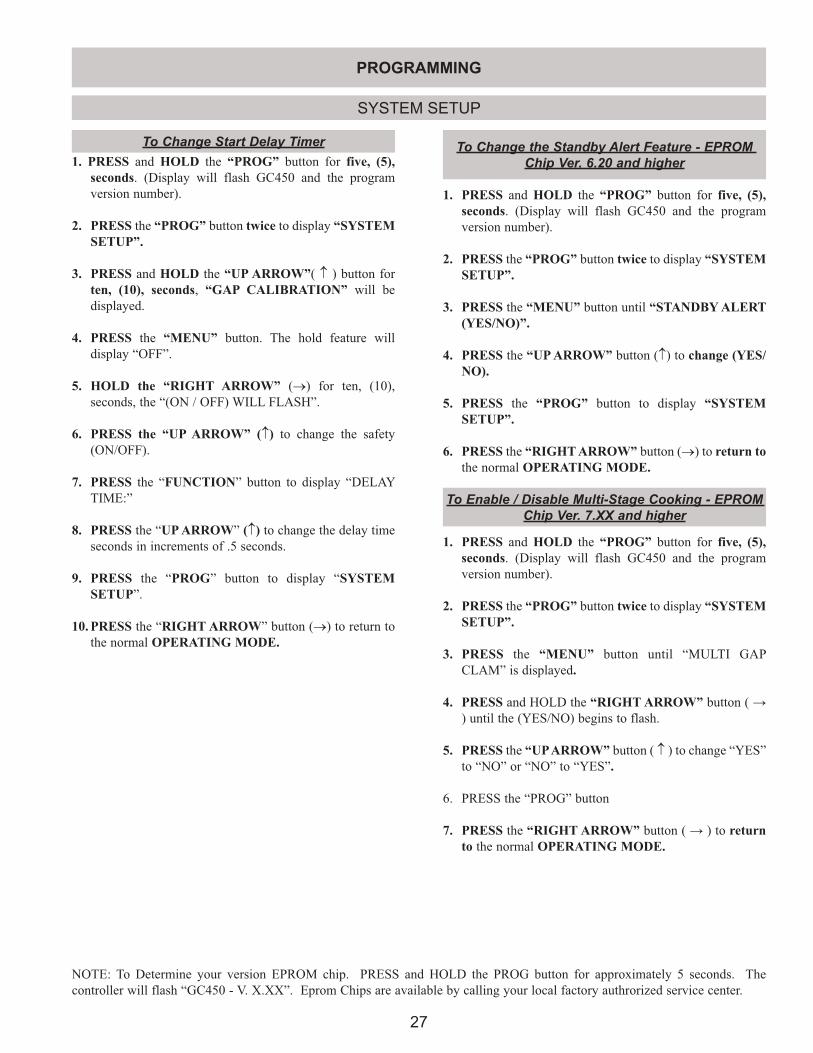
1. PRESS and HOLD the “PROG” button for five, (5), seconds. (Display will flash GC450 and the program version number).
2. PRESS the “PROG” button twice to display “SYSTEM SETUP”.
3. PRESS the “MENU” button until “STANDBY ALERT (YES/NO)”.
4. PRESS the “UP ARROW” button (↑) to change (YES/NO).
5. PRESS the “PROG” button to display “SYSTEM SETUP”.
6. PRESS the “RIGHT ARROW” button (→) to return to the normal OPERATING MODE.
To Change the Standby Alert Feature - EPROM Chip Ver. 6.20 and higher
SYSTEM SETUP
To Change Start Delay Timer1. PRESS and HOLD the “PROG” button for five, (5),
seconds. (Display will flash GC450 and the program version number).
2. PRESS the “PROG” button twice to display “SYSTEM SETUP”.
3. PRESS and HOLD the “UP ARROW”( ↑ ) button for ten, (10), seconds, “GAP CALIBRATION” will be displayed.
4. PRESS the “MENU” button. The hold feature will display “OFF”.
5. HOLD the “RIGHT ARROW” (→) for ten, (10), seconds, the “(ON / OFF) WILL FLASH”.
6. PRESS the “UP ARROW” (↑) to change the safety (ON/OFF).
7. PRESS the “FUNCTION” button to display “DELAY TIME:”
8. PRESS the “UP ARROW” (↑) to change the delay time seconds in increments of .5 seconds.
9. PRESS the “PROG” button to display “SYSTEM SETUP”.
10. PRESS the “RIGHT ARROW” button (→) to return to the normal OPERATING MODE.
To Enable / Disable Multi-Stage Cooking - EPROM Chip Ver. 7.XX and higher
1. PRESS and HOLD the “PROG” button for five, (5), seconds. (Display will flash GC450 and the program version number).
2. PRESS the “PROG” button twice to display “SYSTEM SETUP”.
3. PRESS the “MENU” button until “MULTI GAP CLAM” is displayed.
4. PRESS and HOLD the “RIGHT ARROW” button ( → ) until the (YES/NO) begins to flash.
5. PRESS the “UP ARROW” button ( ↑ ) to change “YES” to “NO” or “NO” to “YES”.
6. PRESS the “PROG” button
7. PRESS the “RIGHT ARROW” button ( → ) to return to the normal OPERATING MODE.
PROGRAMMING
NOTE: To Determine your version EPROM chip. PRESS and HOLD the PROG button for approximately 5 seconds. The controller will flash “GC450 - V. X.XX”. Eprom Chips are available by calling your local factory authrorized service center.
28
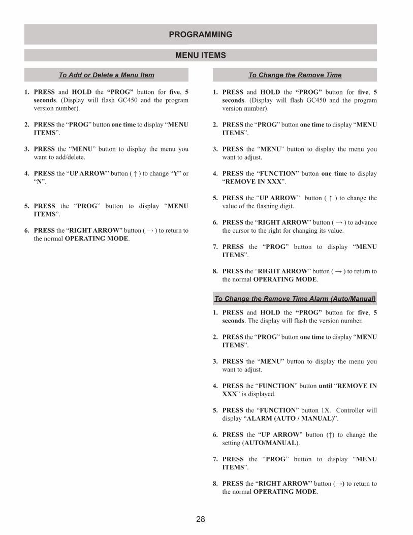
1. PRESS and HOLD the “PROG” button for five, 5 seconds. (Display will flash GC450 and the program version number).
2. PRESS the “PROG” button one time to display “MENU ITEMS”.
3. PRESS the “MENU” button to display the menu you want to add/delete.
4. PRESS the “UP ARROW” button ( ↑ ) to change “Y” or “N”.
5. PRESS the “PROG” button to display “MENU ITEMS”.
6. PRESS the “RIGHT ARROW” button ( → ) to return to the normal OPERATING MODE.
To Add or Delete a Menu Item To Change the Remove Time
1. PRESS and HOLD the “PROG” button for five, 5 seconds. (Display will flash GC450 and the program version number).
2. PRESS the “PROG” button one time to display “MENU ITEMS”.
3. PRESS the “MENU” button to display the menu you want to adjust.
4. PRESS the “FUNCTION” button one time to display “REMOVE IN XXX”.
5. PRESS the “UP ARROW” button ( ↑ ) to change the value of the flashing digit.
6. PRESS the “RIGHT ARROW” button ( → ) to advance the cursor to the right for changing its value.
7. PRESS the “PROG” button to display “MENU ITEMS”.
8. PRESS the “RIGHT ARROW” button ( → ) to return to the normal OPERATING MODE.
MENU ITEMS
1. PRESS and HOLD the “PROG” button for five, 5 seconds. The display will flash the version number.
2. PRESS the “PROG” button one time to display “MENU ITEMS”.
3. PRESS the “MENU” button to display the menu you want to adjust.
4. PRESS the “FUNCTION” button until “REMOVE IN XXX” is displayed.
5. PRESS the “FUNCTION” button 1X. Controller will display “ALARM (AUTO / MANUAL)”.
6. PRESS the “UP ARROW” button (↑) to change the setting (AUTO/MANUAL).
7. PRESS the “PROG” button to display “MENU ITEMS”.
8. PRESS the “RIGHT ARROW” button (→) to return to the normal OPERATING MODE.
To Change the Remove Time Alarm (Auto/Manual)
PROGRAMMING
29
To Change the Sear TimeThe following procedure IS ONLY AVAILABLE and can
only be changed in FLAT MENU ITEMS.
1. PRESS and HOLD the “PROG” button for five, 5 seconds. The display will flash the version number.
2. PRESS the “PROG” button one time to display “MENU ITEMS”.
3. PRESS the “MENU” button to display the menu you want to adjust.
4. PRESS the “FUNCTION” button until “SEAR IN XXX” is displayed on the controller.
NOTE: IF SEAR TIME IS NOT DISPLAYED ON THE CONTROLLER, ENSURE THAT THE CURRENT PRODUCT SELECTED IS A FLAT MENU ITEM.
5. PRESS the “UP ARROW” button (↑) to change the value of the flashing digit.
6. PRESS the “RIGHT ARROW” button (→) to advance the cursor to the right for changing its value.
7. PRESS the “PROG” button to display “MENU ITEMS”.
8. PRESS the “RIGHT ARROW” button (→) to return to the normal OPERATING MODE.
The following procedure IS ONLY AVAILABLE and can only be changed in FLAT MENU ITEMS.
1. PRESS and HOLD the “PROG” button for five, 5 seconds. The display will flash the version number.
2. PRESS the “PROG” button one time to display “MENU ITEMS”.
3. PRESS the “MENU” button to display the menu you want to adjust.
4. PRESS the “FUNCTION” button until “SEAR IN XXX” is displayed.
NOTE: IF SEAR IN IS NOT DISPLAYED ON THE CONTROLLER, ENSURE THAT THE CURRENT PRODUCT SELECTED IS A FLAT MENU ITEM
To Change the Sear Time Alarm (Auto/Manual)
5. PRESS the “FUNCTION” button 1X. Controller will display “ALARM (AUTO / MANUAL)”.
6. PRESS the “UP ARROW” button (↑) to change the setting (AUTO/MANUAL).
7. PRESS the “PROG” button to display “MENU ITEMS”.
8. PRESS the “RIGHT ARROW” button (→) to return to the normal OPERATING MODE.
To Change the Toast Buns Time
1. PRESS and HOLD the “PROG” button for five, 5 seconds. The display will flash the version number.
2. PRESS the “PROG” button one time to display “MENU ITEMS”.
3. PRESS the “MENU” button to display the menu you want to adjust.
4. PRESS the “FUNCTION” button until “TOAST BUNS IN XXX” is displayed.
5. PRESS the “UP ARROW” button (↑) to change the value of the flashing digit.
6. PRESS the “RIGHT ARROW” button (→) to advance the cursor to the right for changing its value.
7. PRESS the “PROG” button to display “MENU ITEMS”.
8. PRESS the “RIGHT ARROW” button (→) to return to the normal OPERATING MODE.
To Change the Toast Buns Alarm (Auto/Manul)
1. PRESS and HOLD the “PROG” button for five, 5 seconds. The display will flash the version number.
2. PRESS the “PROG” button one time to display “MENU ITEMS”.
3. PRESS the “MENU” button to display the menu you want to adjust.
4. PRESS the “FUNCTION” button until “TOAST BUNS IN XXX” is displayed.
PROGRAMMING
MENU ITEMS
30
To Change Turn Time
The following procedure IS ONLY AVAILABLE and can only be changed in FLAT MENU ITEMS.
1. PRESS and HOLD the “PROG” button for five, 5 seconds. The display will flash the version number.
2. PRESS the “PROG” button one time to display “MENU ITEMS”.
3. PRESS the “MENU” button to display the menu you want to adjust.
4. PRESS the “FUNCTION” button until “TURN IN XXX” is displayed on the controller.
NOTE: IF TURN TIME IS NOT DISPLAYED ON THE CONTROLLER, ENSURE THAT THE CURRENT PRODUCT SELECTED IS A FLAT MENU ITEM.
5. PRESS the “UP ARROW” button (↑) to change the value of the flashing digit.
6. PRESS the “RIGHT ARROW” button (→) to advance the cursor to the right for changing its value.
7. PRESS the “PROG” button to display “MENU ITEMS”.
8. PRESS the “RIGHT ARROW” button (→) to return to the normal OPERATING MODE.
To Change Turn In Alarm (Auto / Manual)
The following procedure IS ONLY AVAILABLE and can only be changed in FLAT MENU ITEMS.
5. PRESS the “FUNCTION” button 1X until “ALARM” is displayed.
6. PRESS the “UP ARROW” button (↑) to change the setting (AUTO/MANUAL).
7. PRESS the “PROG” button to display “MENU ITEMS”.
8. PRESS the “RIGHT ARROW” button (→) to return to the normal OPERATING MODE.
1. PRESS and HOLD the “PROG” button for five, 5 seconds. The display will flash the version number.
2. PRESS the “PROG” button one time to display “MENU ITEMS”.
3. PRESS the “MENU” button to display the menu you want to adjust.
4. PRESS the “FUNCTION” button until “TURN IN XXX” is displayed.
NOTE: IF TURN IN IS NOT DISPLAYED ON THE CONTROLLER, ENSURE THAT THE CURRENT PRODUCT SELECTED IS A FLAT MENU ITEM
5. PRESS the “FUNCTION” button 1X. Controller will display “ALARM (AUTO / MANUAL)”.
6. PRESS the “UP ARROW” button (↑) to change the setting (AUTO/MANUAL).
7. PRESS the “PROG” button to display “MENU ITEMS”.
8. PRESS the “RIGHT ARROW” button (→) to return to the normal OPERATING MODE.
To Change the grill surface set temperature
1. PRESS and HOLD the “PROG” button for five, 5 seconds. (Display will flash GC450 and the program version number).
2. PRESS the “PROG” button one time to display “MENU ITEMS”.
3. PRESS the “MENU” button to display the menu you want to adjust.
4. PRESS the “FUNCTION” button three times to display “TOP TEMP”.
5. PRESS the “UP ARROW” button ( ↑ ) to change the value of the flashing digit.
6. PRESS the “RIGHT ARROW” button ( → ) to advance the cursor to the right for changing its value.
7. PRESS the “PROG” button to display “MENU ITEMS”.
8. PRESS the “RIGHT ARROW” button ( → ) to return to the normal OPERATING MODE.
PROGRAMMING
MENU ITEMS
31
MENU ITEMS
1. PRESS and HOLD the “PROG” button for five, 5 seconds. (Display will flash GC450 and the program version number).
2. PRESS the “PROG” button one time to display “MENU ITEMS”.
3. PRESS the “MENU” button to display the menu you want to adjust.
4. PRESS the “FUNCTION” button four times to display “BOTTOM TEMP XXX”
5. PRESS the “UP ARROW” button ( ↑ ) to change the value of the flashing digit.
6. PRESS the “RIGHT ARROW” button ( → ) to advance the cursor to the right for changing its value.
7. PRESS the “PROG” button to display “MENU ITEMS”.
8. PRESS the “RIGHT ARROW” button( → ) to return to the normal OPERATING MODE.
To Change the upper platen set temperature
1. PRESS and HOLD the “PROG” button for five, 5 seconds. (Display will flash GC450 and the program version number).
2. PRESS the “PROG” button one time to display “MENU ITEMS”.
3. PRESS the “MENU” button to display “HIGH LIMIT GRILL”.
4. PRESS the “UP ARROW” button ( ↑ ) to change “Y” or “N”.
5. PRESS the “PROG” button to display “MENU ITEMS”.
6. PRESS the “RIGHT ARROW” button ( → ) to return to the normal OPERATING MODE.
1. PRESS and HOLD the “PROG” button for five, 5 seconds. (Display will flash GC450 and the program version number).
2. PRESS the “PROG” button one time to display “MENU ITEMS”.
3. PRESS the MENU button to display “HIGH LIMIT PLATEN”.
4. PRESS the UP ARROW ( ↑ ) to change “Y” to “N” or “N” to “Y”.
5. PRESS the PROG button to display “MENU ITEMS”.
6. PRESS the RIGHT ARROW button ( → ) to return to the normal operating mode.
To Enable High Limit Test - GRILL SURFACE (Chip V. 3.52 and 4.0* ONLY)
To Enable High Limit Test - PLATEN (Chip V. 3.52 and 4.0* ONLY)
PROGRAMMING
To Change the Gap Setting
1. PRESS and HOLD the "PROG" button for five, (5), seconds. (Display will flash GC450 and the program version number).
2. PRESS the "PROG" button twice to display "SYSTEM SETUP."
3. PRESS and HOLD the "UP ARROW” button (↑) for ten (10) seconds, "GAP CALIBRATION" will be displayed.
4. PRESS the "PROG" button twice to display "MENU ITEMS."
5. PRESS the "MENU" button to display the menu(s) of the gap(s) to be changed.
6. PRESS the "FUNCTION" button to obtain "GAP SETTINGS ".
7. PRESS the "RIGHT ARROW" button (→) to move the cursor, (blinking digit), to the required digit position.
8. PRESS the "UP ARROW" button (↑) to obtain the desired number (O - 9).
9. PRESS the "PROG" button to display "MENU ITEMS".
10. PRESS the "RIGHT ARROW" button (→) to return to the normal OPERATING MODE.
32
MENU ITEMS
TO ADD / PROGRAM NEW MENU ITEMSTo Add / Program an [Option Menu - CLAM]
1. PRESS and HOLD the “PROG” button for five, (5), seconds. (Display will flash GC450 and the program version number).
2. PRESS the “PROG” button twice to display “SYSTEM SETUP.”
3. PRESS and HOLD the “UP ARROW” button ( ↑ ) for ten (10) seconds, “GAP CALIBRATION” will be displayed.
4. PRESS the “PROG” button twice to display “MENU ITEMS.”
5. PRESS the “MENU” button to display “OPTIONAL MENU (1)(2)(3) Clam”.
6. PRESS the “UP ARROW” button ( ↑ ) to change “Y/N”.
7. PRESS the “FUNCTION” button to obtain “REMOVE IN XXX”.
8. PRESS the “UP ARROW” button ( ↑) to obtain the desired number (O - 9).
9. PRESS the “RIGHT ARROW” button (→) to move the cursor, (blinking digit), to the required digit position.
10. PRESS the “FUNCTION” button to display “ALARM ”.
11. PRESS the “UP ARROW” button ( ↑ ) to change the setting (AUTO/MANUAL).
12. PRESS the “FUNCTION” button to display “TOP TEMP”. Top Temp. Default = OFF.
13. PRESS the “UP ARROW” button ( ↑ ) to change the value of the flashing digit.
14. PRESS the “RIGHT ARROW” button ( → ) to advance the cursor to the right for changing its value.
15. PRESS the “FUNCTION” button to display “BOTTOM TEMP XXX”. Bottom Temp. Default = OFF.
16. PRESS the “UP ARROW” button ( ↑ ) to change the value of the flashing digit.
17. PRESS the “RIGHT ARROW” button ( → ) to advance the cursor to the right for changing its value.
18. PRESS the “FUNCTION” button to obtain “GAP SETTING”.
19. PRESS the “UP ARROW” button ( ↑ ) to change the value of the flashing digit.
20. PRESS the “RIGHT ARROW” button ( → ) to advance the cursor to the right for changing its value.
21. PRESS the “FUNCTION” button to obtain display “OPTIONAL MENU CLAM”. To Label the New menu:
22. PRESS the “UP ARROW” button ( ↑ ) to change the value of the flashing digit.
23. PRESS the “RIGHT ARROW” button ( → ) to advance the cursor to the right for changing its value. (Alpha-numeric capabilities).
24. PRESS the “PROG” button to display “MENU ITEMS”.
25. PRESS the “RIGHT ARROW” button (→) to return to the normal OPERATING MODE.
PROGRAMMING
33
To Add / Program an [OPTION MENU - FLAT]
1. PRESS and HOLD the “PROG” button for five, (5), seconds. (Display will flash GC450 and the program version number).
2. PRESS the “PROG” button once to display “MENU ITEMS.”
3. PRESS the “MENU” button to display “OPTIONAL MENU (1)(2)(3) Flat”.
4. PRESS the “UP ARROW” button ( ↑ ) to change “Y/N”.
5. PRESS the “FUNCTION” button to obtain “SEAR IN XXX”.
6. PRESS the “UP ARROW” button ( ↑) to obtain the desired number (O - 9).
7. PRESS the “RIGHT ARROW” button (→) to move the cursor, (blinking digit), to the required digit position.
8. PRESS the “FUNCTION” button to display “ALARM ”.
9. PRESS the “UP ARROW” button ( ↑ ) to change the setting (AUTO/MANUAL).
10. PRESS the “FUNCTION” button to obtain “TURN IN XXX”.
11. PRESS the “UP ARROW” button ( ↑) to obtain the desired number (O - 9).
12. PRESS the “RIGHT ARROW” button (→) to move the cursor, (blinking digit), to the required digit position.
13. PRESS the “FUNCTION” button to display “ALARM ”.
14. PRESS the “UP ARROW” button ( ↑ ) to change the setting (AUTO/MANUAL).
15. PRESS the “FUNCTION” button to display “REMOVE IN ”.
16. PRESS the “UP ARROW” button ( ↑) to obtain the desired number (O - 9).
17. PRESS the “RIGHT ARROW” button (→) to move the cursor, (blinking digit), to the required digit position.
18. PRESS the “FUNCTION” button to display “ALARM ”.
19. PRESS the “UP ARROW” button ( ↑ ) to change the setting (AUTO/MANUAL).
20. PRESS the “FUNCTION” button to display “TOP TEMP”. Flat Mode Top Temp is set to OFF.
21. PRESS the “FUNCTION” button to display “BOTTOM TEMP XXX”. Bottom Temp. Default = OFF.
22. Press the “UP ARROW” button ( ↑ ) to change the value of the flashing digit.
23. PRESS the “RIGHT ARROW” button ( → ) to advance the cursor to the right for changing its value.
24. PRESS the “FUNCTION” button to obtain display “OPTIONAL MENU FLAT”. To Label the New menu:
25. PRESS the “UP ARROW” button ( ↑ ) to change the value of the flashing digit.
26. PRESS the “RIGHT ARROW” button ( → ) to advance the cursor to the right for changing its value. (Alpha-numeric capabilities).
27. PRESS the “PROG” button to display “MENU ITEMS”.
28. PRESS the “RIGHT ARROW” button (→) to return to the normal OPERATING MODE.
PROGRAMMING
MENU ITEMS
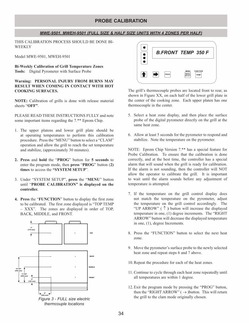
34
PROBE CALIBRATION
19 3/8”
(492 mm)
11 5/8”
(295 mm)
4”
(102 mm)
9”
(229 mm)
7”
(179 mm)
TOP
BACK
FRONT
MIDDLE
MWE-9501, MWEH-9501 (FULL SIZE & HALF SIZE UNITS WITH 4 ZONES PER HALF)
TEMP
MENU FUNCTION
PROG MENUSELECT
PROG
B.FRONT TEMP 350 F
The grill’s thermocouple probes are located front to rear, as shown in Figure XX, on each half of the lower grill plate in the center of the cooking zone. Each upper platen has one thermocouple in the center.
5. Select a heat zone display, and then place the surface probe of the digital pyrometer directly on the grill at the same heat zone.
6. Allow at least 5 seconds for the pyrometer to respond and stabilize. Note the temperature on the pyrometer.
NOTE: Eprom Chip Version 7.** has a special feature for Probe Calibration. To ensure that the calibration is done correctly, and at the best time, the controller has a special alarm that will sound when the grill is ready for calibration. If the alarm is not sounding, then the controller will NOT allow the operator to calibrate the grill. It is important to wait until the alarm sounds before any adjustment of temperature is attempted.
7. If the temperature on the grill control display does not match the temperature on the pyrometer, adjust the temperature on the grill control accordingly. The “UP ARROW” ( ↑ ) button will increase the displayed temperature in one, (1) degree increments. The “RIGHT ARROW” button will decrease the displayed temperature in one, (1), degree Increments.
8. Press the “FUNCTION” button to select the next heat
zone.
9. Move the pyrometer’s surface probe to the newly selected heat zone and repeat steps 6 and 7 above.
10. Repeat the procedure for each of the heat zones.
11. Continue to cycle through each heat zone repeatedly until all temperatures are within 1 degree.
12. Exit the program mode by pressing the “PROG” button, then the “RIGHT ARROW” ( → )button. This will return the grill to the clam mode originally chosen.Figure 3 - FULL size electric
thermcouple locations
THIS CALIBRATION PROCESS SHOULD BE DONE BI-WEEKLY
Model MWE-9501, MWEH-9501
Bi-Weekly Calibration of Grill Temperature ZonesTools: Digital Pyrometer with Surface Probe
Warning: PERSONAL INJURY FROM BURNS MAY RESULT WHEN COMING IN CONTACT WITH HOT COOKING SURFACES.
NOTE: Calibration of grills is done with release material sheets “OFF”.
PLEASE READ THESE INSTRUCTIONS FULLY and note some important items regarding the 7.** Eprom Chip.
1. The upper platens and lower grill plate should be at operating temperatures to perform this calibration procedure. Press the “MENU” button to select a “CLAM” operation and allow the grill to reach the set temperature and stabilize, (approximately 30 minutes).
2. Press and hold the “PROG” button for 5 seconds to enter the program mode, then press “PROG” button (2) times to access the “SYSTEM SETUP”.
3. Under “SYSTEM SETUP”, press the “MENU” button until “PROBE CALIBRATION” is displayed on the controller.
4. Press the “FUNCTION” button to display the first zone to be calibrated. The first zone displayed is “TOP TEMP – XXX”. The zones are displayed in order of TOP, BACK, MIDDLE, and FRONT.
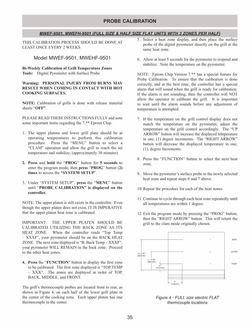
35
MWEF-9501, MWEFH-9501 (FULL SIZE & HALF SIZE FLAT UNITS WITH 3 ZONES PER HALF)
THIS CALIBRATION PROCESS SHOULD BE DONE AT LEAST ONCE EVERY 2 WEEKS
Model MWEF-9501, MWEHF-9501
Bi-Weekly Calibration of Grill Temperature ZonesTools: Digital Pyrometer with Surface Probe
Warning: PERSONAL INJURY FROM BURNS MAY RESULT WHEN COMING IN CONTACT WITH HOT COOKING SURFACES.
NOTE: Calibration of grills is done with release material sheets “OFF”.
PLEASE READ THESE INSTRUCTIONS FULLY and note some important items regarding the 7.** Eprom Chip.
1. The upper platens and lower grill plate should be at operating temperatures to perform this calibration procedure. Press the “MENU” button to select a “CLAM” operation and allow the grill to reach the set temperature and stabilize, (approximately 30 minutes).
2. Press and hold the “PROG” button for 5 seconds to enter the program mode, then press “PROG” button (2) times to access the “SYSTEM SETUP”.
3. Under “SYSTEM SETUP”, press the “MENU” button until “PROBE CALIBRATION” is displayed on the controller.
NOTE: The upper platen is still exists in the controller. Even though the upper platen does not exist, IT IS IMPERATIVE that the upper platen heat zone is calibrated.
IMPORTANT: THE UPPER PLATEN SHOULD BE CALIBRATED UTILIZING THE BACK ZONE AS ITS HEAT ZONE. When the controller reads “Top Temp – XXXF”, your pyrometer should be on the BACK HEAT ZONE. The next zone displayed is “B. Back Temp – XXXF”, your pyrometer WILL REMAIN in the back zone. Proceed to the other heat zones.
4. Press the “FUNCTION” button to display the first zone to be calibrated. The first zone displayed is “TOP TEMP – XXX”. The zones are displayed in order of TOP, BACK, MIDDLE, and FRONT.
The grill’s thermocouple probes are located front to rear, as shown in Figure 4, on each half of the lower grill plate in the center of the cooking zone. Each upper platen has one thermocouple in the center.
5. Select a heat zone display, and then place the surface probe of the digital pyrometer directly on the grill at the same heat zone.
6. Allow at least 5 seconds for the pyrometer to respond and stabilize. Note the temperature on the pyrometer.
NOTE: Eprom Chip Version 7.** has a special feature for Probe Calibration. To ensure that the calibration is done correctly, and at the best time, the controller has a special alarm that will sound when the grill is ready for calibration. If the alarm is not sounding, then the controller will NOT allow the operator to calibrate the grill. It is important to wait until the alarm sounds before any adjustment of temperature is attempted.
7. If the temperature on the grill control display does not match the temperature on the pyrometer, adjust the temperature on the grill control accordingly. The “UP ARROW” button will increase the displayed temperature in one, (1) degree increments. The “RIGHT ARROW” button will decrease the displayed temperature in one, (1), degree Increments.
8. Press the “FUNCTION” button to select the next heat
zone.
9. Move the pyrometer’s surface probe to the newly selected heat zone and repeat steps 6 and 7 above.
10. Repeat the procedure for each of the heat zones.
11. Continue to cycle through each heat zone repeatedly until all temperatures are within 1 degree.
12. Exit the program mode by pressing the “PROG” button, then the “RIGHT ARROW” button. This will return the grill to the clam mode originally chosen.
PROBE CALIBRATION
Figure 4 - FULL size electric FLAT thermcouple locations
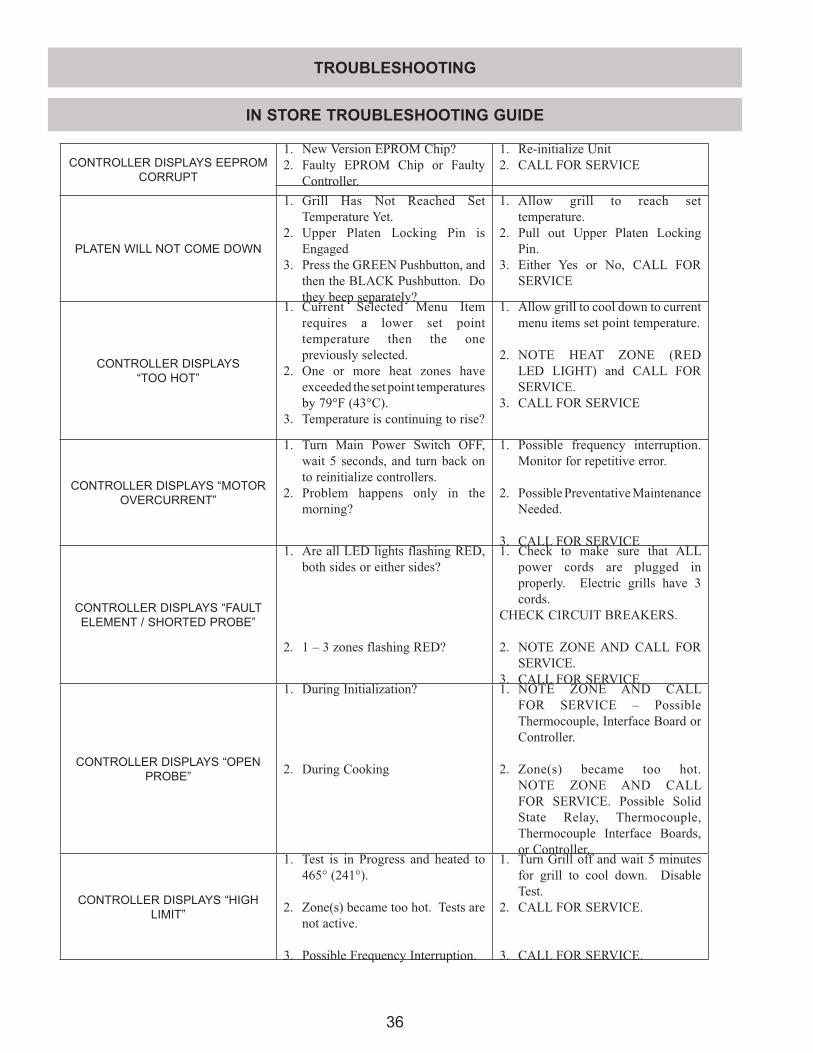
36
IN STORE TROUBLESHOOTING GUIDE
CONTROLLER DISPLAYS EEPROM CORRUPT
1. New Version EPROM Chip?2. Faulty EPROM Chip or Faulty
Controller.
1. Re-initialize Unit2. CALL FOR SERVICE
PLATEN WILL NOT COME DOWN
1. Grill Has Not Reached Set Temperature Yet.
2. Upper Platen Locking Pin is Engaged
3. Press the GREEN Pushbutton, and then the BLACK Pushbutton. Do they beep separately?
1. Allow grill to reach set temperature.
2. Pull out Upper Platen Locking Pin.
3. Either Yes or No, CALL FOR SERVICE
CONTROLLER DISPLAYS “TOO HOT”
1. Current Selected Menu Item requires a lower set point temperature then the one previously selected.
2. One or more heat zones have exceeded the set point temperatures by 79°F (43°C).
3. Temperature is continuing to rise?
1. Allow grill to cool down to current menu items set point temperature.
2. NOTE HEAT ZONE (RED LED LIGHT) and CALL FOR SERVICE.
3. CALL FOR SERVICE
CONTROLLER DISPLAYS “MOTOR OVERCURRENT”
1. Turn Main Power Switch OFF, wait 5 seconds, and turn back on to reinitialize controllers.
2. Problem happens only in the morning?
1. Possible frequency interruption. Monitor for repetitive error.
2. Possible Preventative Maintenance Needed.
3. CALL FOR SERVICE
CONTROLLER DISPLAYS “FAULT ELEMENT / SHORTED PROBE”
1. Are all LED lights flashing RED, both sides or either sides?
2. 1 – 3 zones flashing RED?
1. Check to make sure that ALL power cords are plugged in properly. Electric grills have 3 cords.
CHECK CIRCUIT BREAKERS.
2. NOTE ZONE AND CALL FOR SERVICE.
3. CALL FOR SERVICE
CONTROLLER DISPLAYS “OPEN PROBE”
1. During Initialization?
2. During Cooking
1. NOTE ZONE AND CALL FOR SERVICE – Possible Thermocouple, Interface Board or Controller.
2. Zone(s) became too hot. NOTE ZONE AND CALL FOR SERVICE. Possible Solid State Relay, Thermocouple, Thermocouple Interface Boards, or Controller.
CONTROLLER DISPLAYS “HIGH LIMIT”
1. Test is in Progress and heated to 465° (241°).
2. Zone(s) became too hot. Tests are not active.
3. Possible Frequency Interruption.
1. Turn Grill off and wait 5 minutes for grill to cool down. Disable Test.
2. CALL FOR SERVICE.
3. CALL FOR SERVICE.
TROUBLESHOOTING
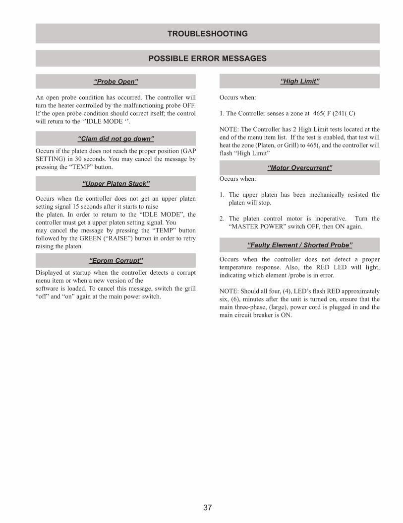
37
“Probe Open”
“Clam did not go down”
“Upper Platen Stuck”
“High Limit”
“Eprom Corrupt”
“Faulty Element / Shorted Probe”
“Motor Overcurrent”
POSSIBLE ERROR MESSAGES
An open probe condition has occurred. The controller will turn the heater controlled by the malfunctioning probe OFF. If the open probe condition should correct itself; the control will return to the ‘’IDLE MODE ‘’.
Occurs if the platen does not reach the proper position (GAP SETTING) in 30 seconds. You may cancel the message by pressing the “TEMP” button.
Occurs when the controller does not get an upper platen setting signal 15 seconds after it starts to raisethe platen. In order to return to the “IDLE MODE”, the controller must get a upper platen setting signal. Youmay cancel the message by pressing the “TEMP” button followed by the GREEN (“RAISE”) button in order to retry raising the platen.
Displayed at startup when the controller detects a corrupt menu item or when a new version of thesoftware is loaded. To cancel this message, switch the grill “off” and “on” again at the main power switch.
Occurs when the controller does not detect a proper temperature response. Also, the RED LED will light, indicating which element /probe is in error.
NOTE: Should all four, (4), LED’s flash RED approximately six, (6), minutes after the unit is turned on, ensure that the main three-phase, (large), power cord is plugged in and the main circuit breaker is ON.
Occurs when:
1. The Controller senses a zone at 465( F (241( C)
NOTE: The Controller has 2 High Limit tests located at the end of the menu item list. If the test is enabled, that test will heat the zone (Platen, or Grill) to 465(, and the controller will flash “High Limit”
Occurs when:
1. The upper platen has been mechanically resisted the platen will stop.
2. The platen control motor is inoperative. Turn the “MASTER POWER” switch OFF, then ON again.
TROUBLESHOOTING
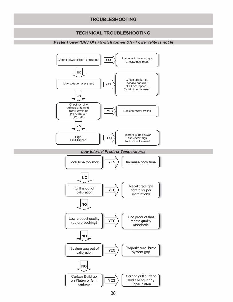
38
TROUBLESHOOTING
TECHNICAL TROUBLESHOOTING
Master Power (ON / OFF) Switch turned ON - Power telite is not lit
Control power cord(s) unplugged Reconnect power supplyCheck Ansul reset
Line voltage not present
Circuit breaker atservice panel is
“OFF” or tripped,Reset circuit breaker
Check for Linevoltage at terminal
block terminals(#1 & #6) and
(#2 & #6)
YES
YES
NO
NO
Replace power switch
NO
HighLimit Tripped
-
Remove platen coverand check high
limit...Check cause!
YES
YES
Low Internal Product Temperatures
Cook time too short
Grill is out ofcalibration
Low product quality(before cooking)
Increase cook time
Recalibrate grillcontroller perinstructions
Use product thatmeets quality
standards
System gap out ofcalibration
NO
NO
NO
YES
YES
YES
YESProperly recalibrate
system gap
Carbon Build upon Platen or Grill
surface
NO
YES
Scrape grill surfaceand / or squeegy
upper platen
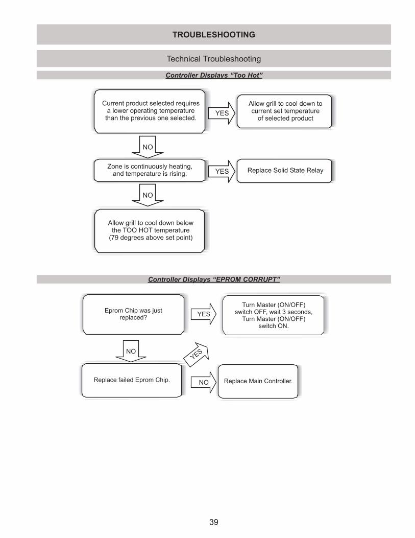
39
Technical Troubleshooting
Controller Displays “Too Hot”
Controller Displays “EPROM CORRUPT”
TROUBLESHOOTING
Allow grill to cool down tocurrent set temperature
of selected product
Current product selected requiresa lower operating temperature
than the previous one selected.
Zone is continuously heating,and temperature is rising.
Replace Solid State Relay
Allow grill to cool down belowthe TOO HOT temperature
(79 degrees above set point)
YES
NO
YES
NO
Eprom Chip was justreplaced?
Turn Master (ON/OFF)switch OFF, wait 3 seconds,
Turn Master (ON/OFF)switch ON.
NO
Replace failed Eprom Chip.
YES
Replace Main Controller.
YES
NO
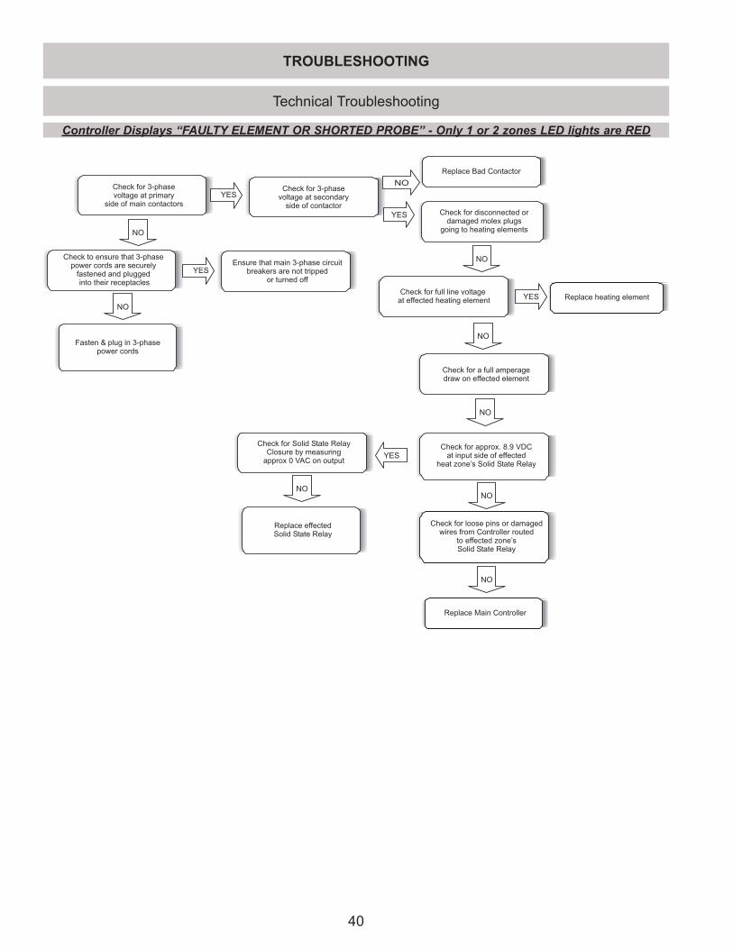
40
Technical Troubleshooting
Controller Displays “FAULTY ELEMENT OR SHORTED PROBE” - Only 1 or 2 zones LED lights are RED
NO
YES
YES
YES
YES
YES
NO
NO
NO
NONO
NO
NO
NO
Check for 3-phasevoltage at primary
side of main contactors
Check for 3-phasevoltage at secondary
side of contactor
Replace Bad Contactor
Check for disconnected ordamaged molex plugs
going to heating elements
Check to ensure that 3-phasepower cords are securely
fastened and pluggedinto their receptacles
Ensure that main 3-phase circuitbreakers are not tripped
or turned off
Check for full line voltageat effected heating element Replace heating element
Fasten & plug in 3-phasepower cords
Check for a full amperagedraw on effected element
Check for Solid State RelayClosure by measuring
approx 0 VAC on output
Check for approx. 8.9 VDCat input side of effected
heat zone’s Solid State Relay
Check for loose pins or damagedwires from Controller routed
to effected zone’sSolid State Relay
Replace Main Controller
Replace effectedSolid State Relay
TROUBLESHOOTING
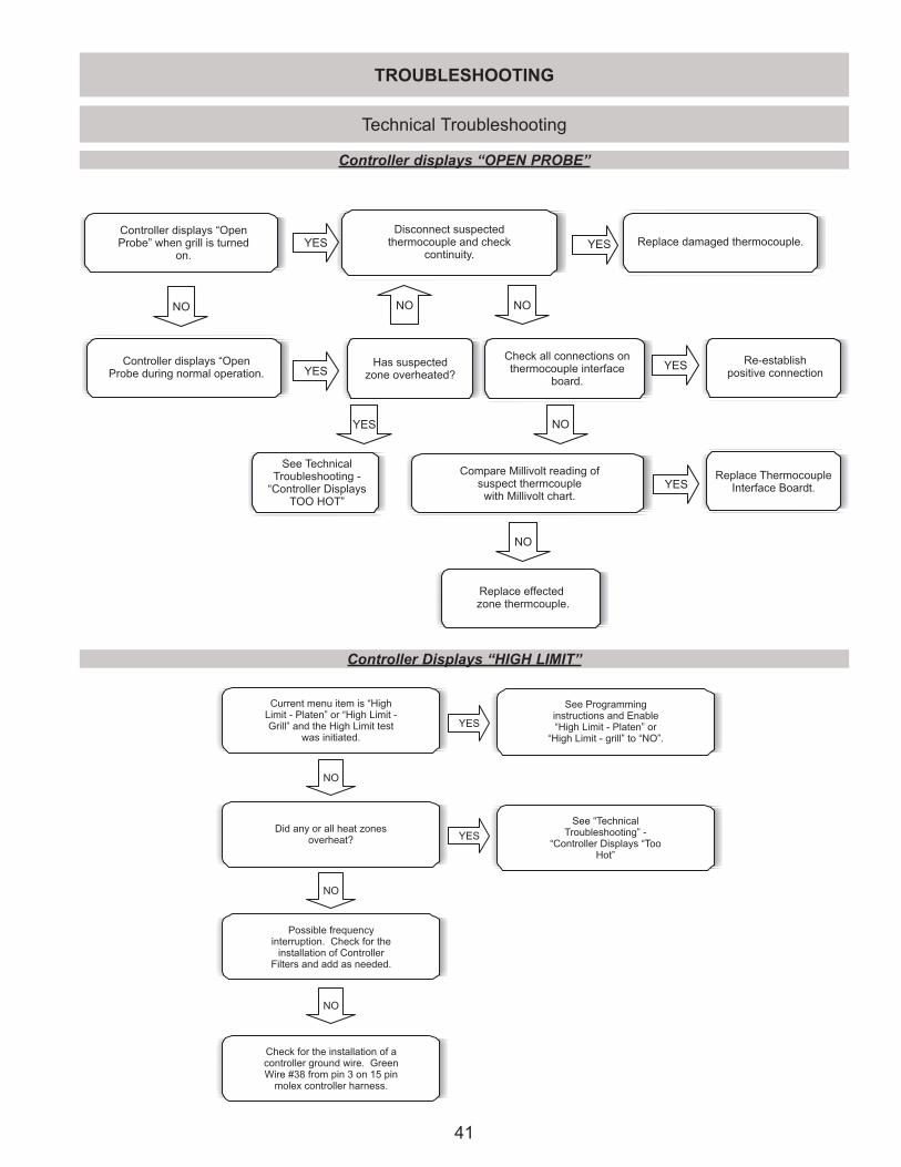
41
Technical Troubleshooting
Controller displays “OPEN PROBE”
Controller displays “OpenProbe” when grill is turned
on.
NO
Controller displays “OpenProbe during normal operation.
Disconnect suspectedthermocouple and check
continuity.
Has suspectedzone overheated?
YES
YES
Replace damaged thermocouple.YES
NO NO
Check all connections onthermocouple interface
board.
YES Re-establishpositive connection
NO
Compare Millivolt reading ofsuspect thermcouple
with Millivolt chart.
NO
Replace effectedzone thermcouple.
Replace ThermocoupleInterface Boardt.YES
YES
See TechnicalTroubleshooting -
“Controller DisplaysTOO HOT”
Controller Displays “HIGH LIMIT”
See “TechnicalTroubleshooting” -
“Controller Displays “TooHot”
Current menu item is “HighLimit - Platen” or “High Limit -Grill” and the High Limit test
was initiated.
NO
Did any or all heat zonesoverheat?
Possible frequencyinterruption. Check for the
installation of ControllerFilters and add as needed.
Check for the installation of acontroller ground wire. GreenWire #38 from pin 3 on 15 pin
molex controller harness.
NO
NO
See Programminginstructions and Enable“High Limit - Platen” or
“High Limit - grill” to “NO”.
YES
YES
TROUBLESHOOTING
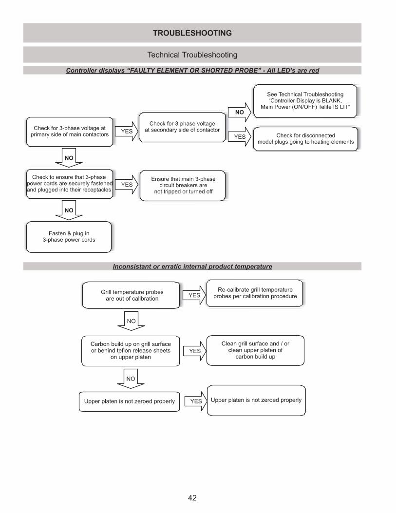
42
Technical Troubleshooting
Controller displays “FAULTY ELEMENT OR SHORTED PROBE” - All LED’s are red
Check for 3-phase voltage atprimary side of main contactors
See Technical Troubleshooting“Controller Display is BLANK,
Main Power (ON/OFF) Telite IS LIT”
Ensure that main 3-phasecircuit breakers are
not tripped or turned off
Check for 3-phase voltageat secondary side of contactorYES
YES
NO
Check for disconnectedmodel plugs going to heating elements
Check to ensure that 3-phasepower cords are securely fastenedand plugged into their receptacles
YES
NO
Fasten & plug in3-phase power cords
NO
Inconsistant or erratic internal product temperature
Grill temperature probesare out of calibration
Carbon build up on grill surfaceor behind teflon release sheets
on upper platen
Upper platen is not zeroed properly
Re-calibrate grill temperatureprobes per calibration procedure
Clean grill surface and / orclean upper platen of
carbon build up
Upper platen is not zeroed properly
NO
NO
YES
YES
YES
TROUBLESHOOTING
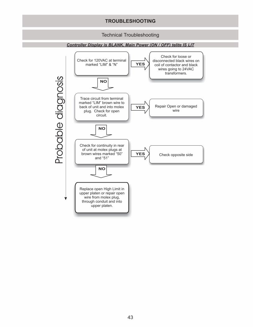
43
Technical Troubleshooting
Controller Display is BLANK, Main Power (ON / OFF) telite IS LIT
Trace circuit from terminalmarked “LIM” brown wire toback of unit and into molex
plug. Check for opencircuit.
Check for 120VAC at terminalmarked “LIM” & “N”
NO
YES
NO
Check for continuity in rearof unit at molex plugs atbrown wires marked “50”
and “51”
NO
Replace open High Limit inupper platen or repair open
wire from molex plug,through conduit and into
upper platen.
Pro
ba
ble
dia
gno
sis
Check for loose ordisconnected black wires oncoil of contactor and black
wires going to 24VACtransformers.
YES Repair Open or damagedwire
YES Check opposite side
TROUBLESHOOTING
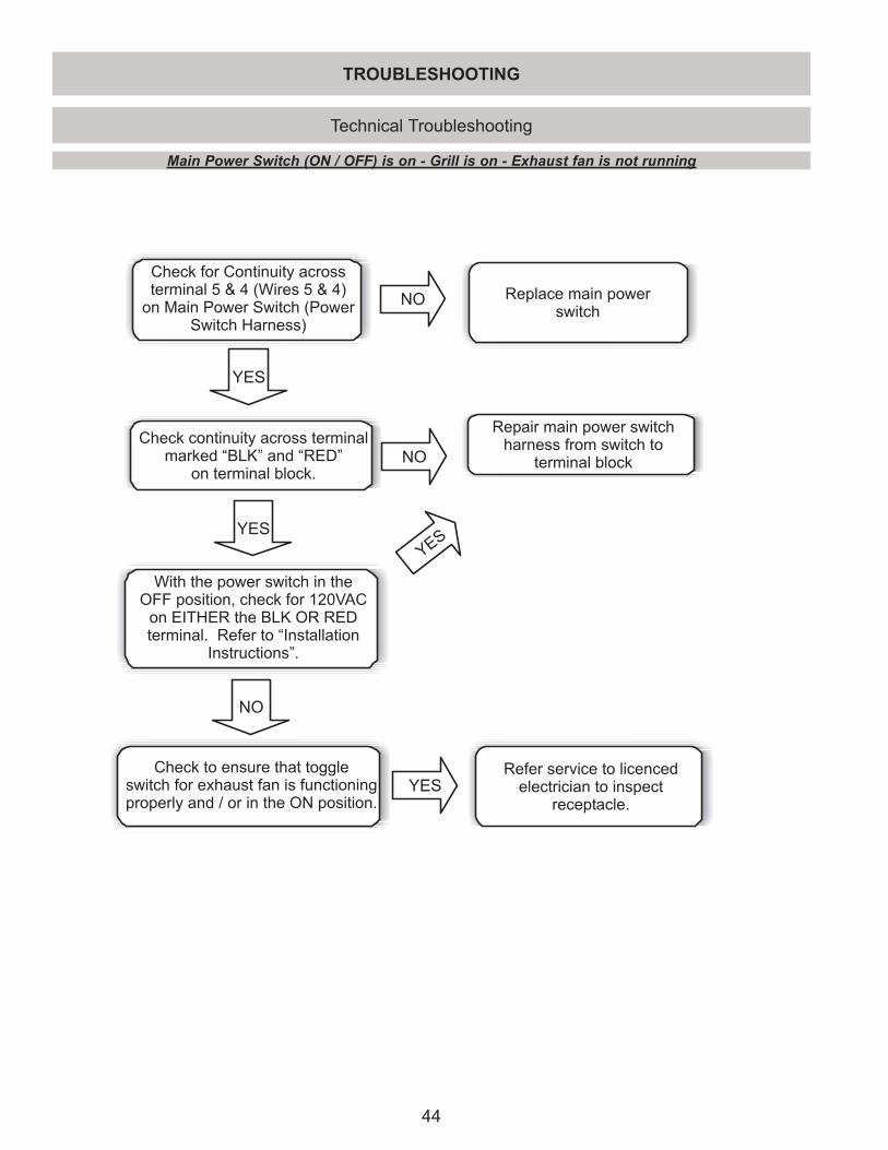
44
Check for Continuity acrossterminal 5 & 4 (Wires 5 & 4)
on Main Power Switch (PowerSwitch Harness)
Check continuity across terminalmarked “BLK” and “RED”
on terminal block.NO
Replace main powerswitch
NO
With the power switch in theOFF position, check for 120VAC
on EITHER the BLK OR REDterminal. Refer to “Installation
Instructions”.
YES
YES
NO
Refer service to licencedelectrician to inspect
receptacle.
Repair main power switchharness from switch to
terminal block
Check to ensure that toggleswitch for exhaust fan is functioningproperly and / or in the ON position.
YES
YES
TROUBLESHOOTING
Technical Troubleshooting
Main Power Switch (ON / OFF) is on - Grill is on - Exhaust fan is not running
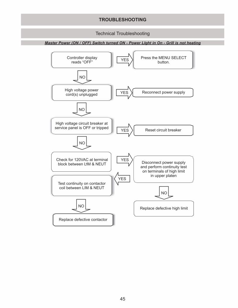
45
TROUBLESHOOTING
Technical Troubleshooting
Master Power (ON / OFF) Switch turned ON - Power LIght in On - Grill is not heating
-
Controller displayreads “OFF”
Press the MENU SELECTbutton.
High voltage circuit breaker atservice panel is OFF or tripped
YES Reconnect power supply
YES
NO
Reset circuit breaker
Check for 120VAC at terminalblock between LIM & NEUT
YES
YES
Disconnect power supplyand perform continuity teston terminals of high limit
in upper platen
High voltage powercord(s) unplugged
NO
NO
NO
YES
Test continuity on contactorcoil between LIM & NEUT
NO
Replace defective contactor
Replace defective high limit
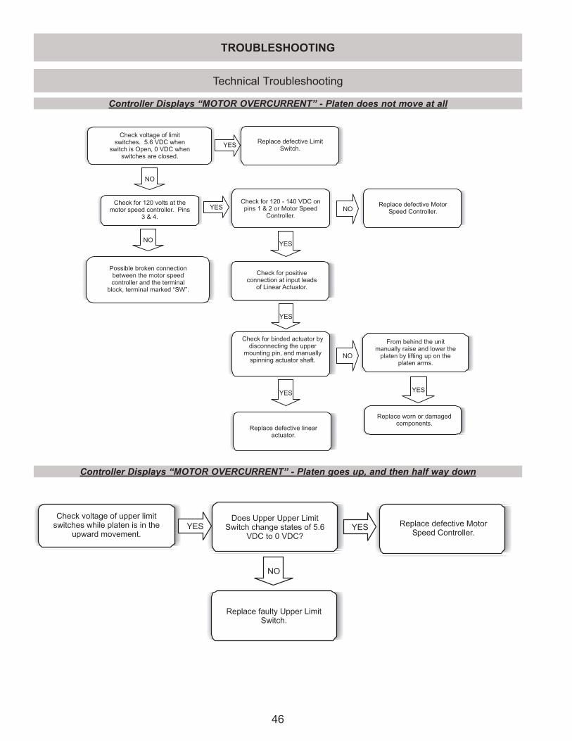
46
Technical Troubleshooting
Controller Displays “MOTOR OVERCURRENT” - Platen does not move at all
TROUBLESHOOTING
NO
Replace defective LimitSwitch.
Check voltage of limitswitches. 5.6 VDC when
switch is Open, 0 VDC whenswitches are closed.
YES
Check for positiveconnection at input leads
of Linear Actuator.
YESNO
Possible broken connectionbetween the motor speedcontroller and the terminal
block, terminal marked “SW”.
Check for 120 - 140 VDC onpins 1 & 2 or Motor Speed
Controller.
YES
YES
Replace defective linearactuator.
YES
Check for binded actuator bydisconnecting the upper
mounting pin, and manuallyspinning actuator shaft.
NO
NO
Replace worn or damagedcomponents.
YES
From behind the unitmanually raise and lower the
platen by lifting up on theplaten arms.
Replace defective MotorSpeed Controller.
Check for 120 volts at themotor speed controller. Pins
3 & 4.
Controller Displays “MOTOR OVERCURRENT” - Platen goes up, and then half way down
Check voltage of upper limitswitches while platen is in the
upward movement.
NO
Does Upper Upper LimitSwitch change states of 5.6
VDC to 0 VDC?
YES Replace defective MotorSpeed Controller.
YES
Replace faulty Upper LimitSwitch.
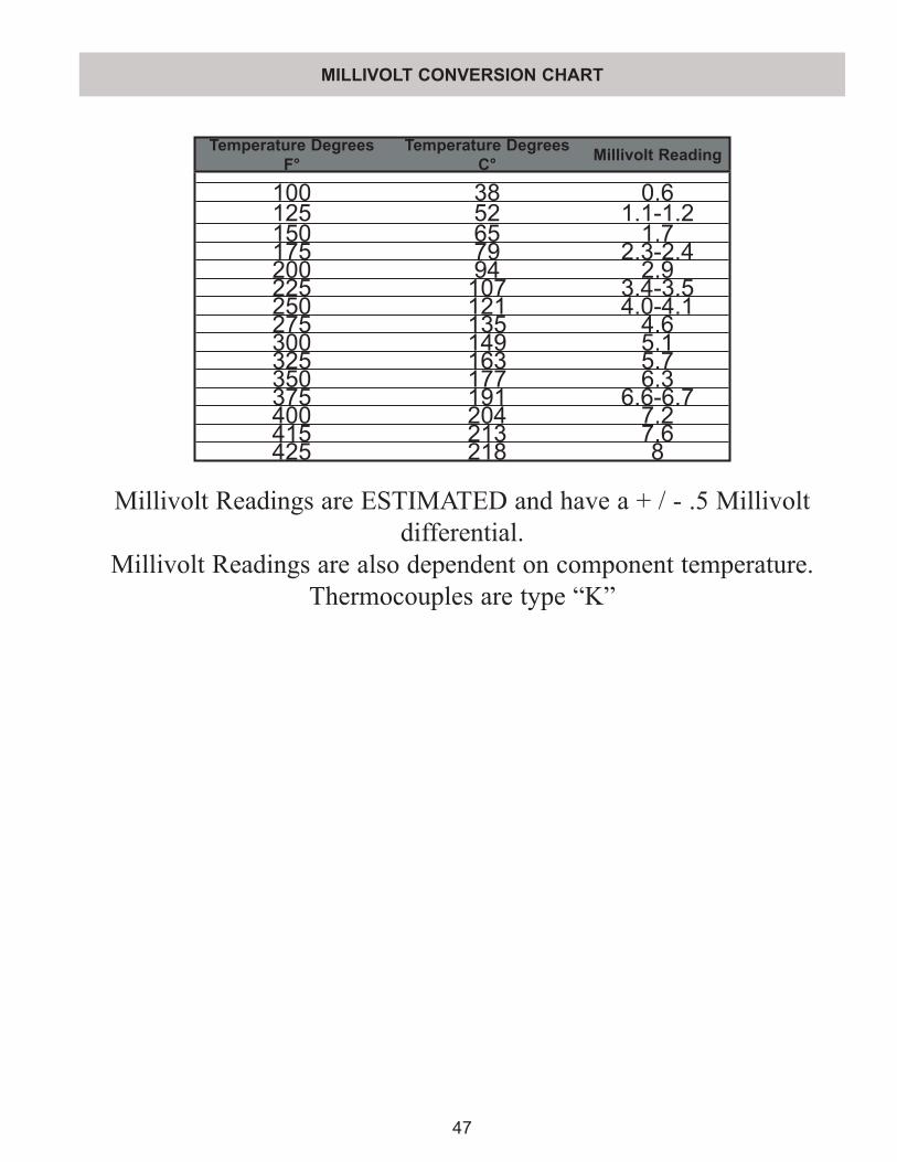
47
MILLIVOLT CONVERSION CHART
Temperature Degrees F°
Temperature Degrees C° Millivolt Reading
100 38 0.6125 52 1.1-1.2150 65 1.7175 79 2.3-2.4200 94 2.9225 107 3.4-3.5250 121 4.0-4.1275 135 4.6300 149 5.1325 163 5.7350 177 6.3375 191 6.6-6.7400 204 7.2415 213 7.6425 218 8
Millivolt Readings are ESTIMATED and have a + / - .5 Millivolt differential.
Millivolt Readings are also dependent on component temperature.Thermocouples are type “K”
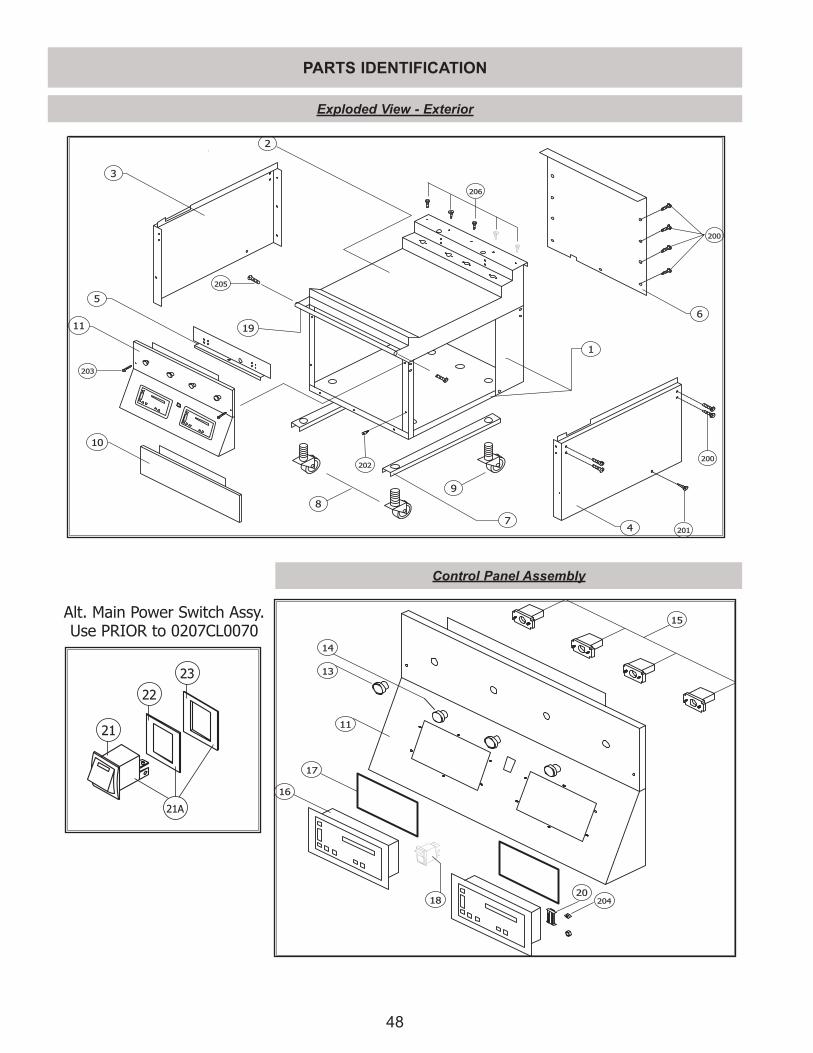
48
PARTS IDENTIFICATIONPARTS IDENTIFICATION
15
14
13
17
18
16
204
20
11
1
2
3
4
5
6
7
8
9
11
10
200
202
203
200
201
19
205
206
21
22
23
21A
Alt. Main Power Switch Assy.Use PRIOR to 0207CL0070
Exploded View - Exterior
Control Panel Assembly
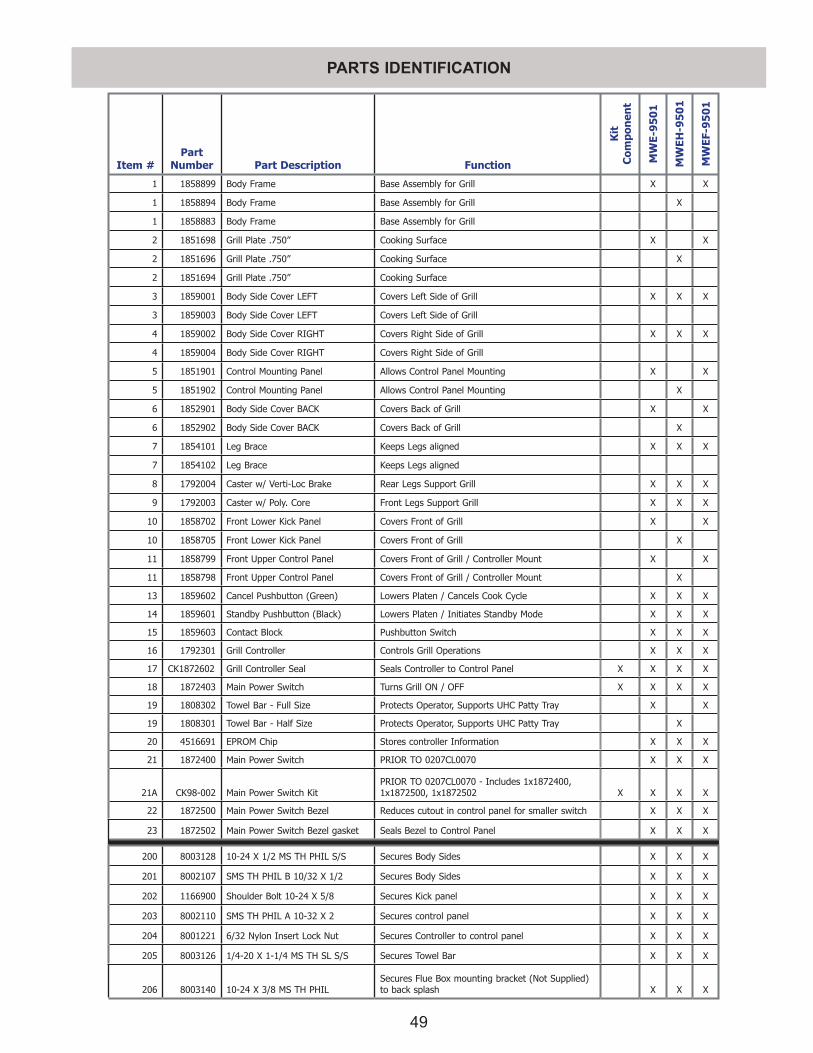
49
PARTS IDENTIFICATIONPARTS IDENTIFICATION
Item #Part
Number Part Description Function
Kit
C
ompo
nen
t
MW
E-9
50
1
MW
EH-9
50
1
MW
EF-9
50
1
1 1858899 Body Frame Base Assembly for Grill X X
1 1858894 Body Frame Base Assembly for Grill X
1 1858883 Body Frame Base Assembly for Grill
2 1851698 Grill Plate .750” Cooking Surface X X
2 1851696 Grill Plate .750” Cooking Surface X
2 1851694 Grill Plate .750” Cooking Surface
3 1859001 Body Side Cover LEFT Covers Left Side of Grill X X X
3 1859003 Body Side Cover LEFT Covers Left Side of Grill
4 1859002 Body Side Cover RIGHT Covers Right Side of Grill X X X
4 1859004 Body Side Cover RIGHT Covers Right Side of Grill
5 1851901 Control Mounting Panel Allows Control Panel Mounting X X
5 1851902 Control Mounting Panel Allows Control Panel Mounting X
6 1852901 Body Side Cover BACK Covers Back of Grill X X
6 1852902 Body Side Cover BACK Covers Back of Grill X
7 1854101 Leg Brace Keeps Legs aligned X X X
7 1854102 Leg Brace Keeps Legs aligned
8 1792004 Caster w/ Verti-Loc Brake Rear Legs Support Grill X X X
9 1792003 Caster w/ Poly. Core Front Legs Support Grill X X X
10 1858702 Front Lower Kick Panel Covers Front of Grill X X
10 1858705 Front Lower Kick Panel Covers Front of Grill X
11 1858799 Front Upper Control Panel Covers Front of Grill / Controller Mount X X
11 1858798 Front Upper Control Panel Covers Front of Grill / Controller Mount X
13 1859602 Cancel Pushbutton (Green) Lowers Platen / Cancels Cook Cycle X X X
14 1859601 Standby Pushbutton (Black) Lowers Platen / Initiates Standby Mode X X X
15 1859603 Contact Block Pushbutton Switch X X X
16 1792301 Grill Controller Controls Grill Operations X X X
17 CK1872602 Grill Controller Seal Seals Controller to Control Panel X X X X
18 1872403 Main Power Switch Turns Grill ON / OFF X X X X
19 1808302 Towel Bar - Full Size Protects Operator, Supports UHC Patty Tray X X
19 1808301 Towel Bar - Half Size Protects Operator, Supports UHC Patty Tray X
20 4516691 EPROM Chip Stores controller Information X X X
21 1872400 Main Power Switch PRIOR TO 0207CL0070 X X X
21A CK98-002 Main Power Switch KitPRIOR TO 0207CL0070 - Includes 1x1872400, 1x1872500, 1x1872502 X X X X
22 1872500 Main Power Switch Bezel Reduces cutout in control panel for smaller switch X X X
23 1872502 Main Power Switch Bezel gasket Seals Bezel to Control Panel X X X
200 8003128 10-24 X 1/2 MS TH PHIL S/S Secures Body Sides X X X
201 8002107 SMS TH PHIL B 10/32 X 1/2 Secures Body Sides X X X
202 1166900 Shoulder Bolt 10-24 X 5/8 Secures Kick panel X X X
203 8002110 SMS TH PHIL A 10-32 X 2 Secures control panel X X X
204 8001221 6/32 Nylon Insert Lock Nut Secures Controller to control panel X X X
205 8003126 1/4-20 X 1-1/4 MS TH SL S/S Secures Towel Bar X X X
206 8003140 10-24 X 3/8 MS TH PHILSecures Flue Box mounting bracket (Not Supplied) to back splash X X X
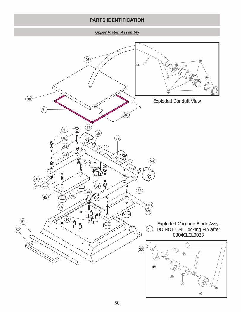
50
PARTS IDENTIFICATION
210
209
200
39
38
44
43
42
41
60
209 208
45
51
52
49
46
38
53
50
30
207
40
26
31
40A
57
54
61
2628
29
272726A
26B26B
5757
56
55
54
36
35
3737
34
33
Exploded Carriage Block Assy.DO NOT USE Locking Pin after
0304CLCL0023
Exploded Conduit View
Upper Platen Assembly
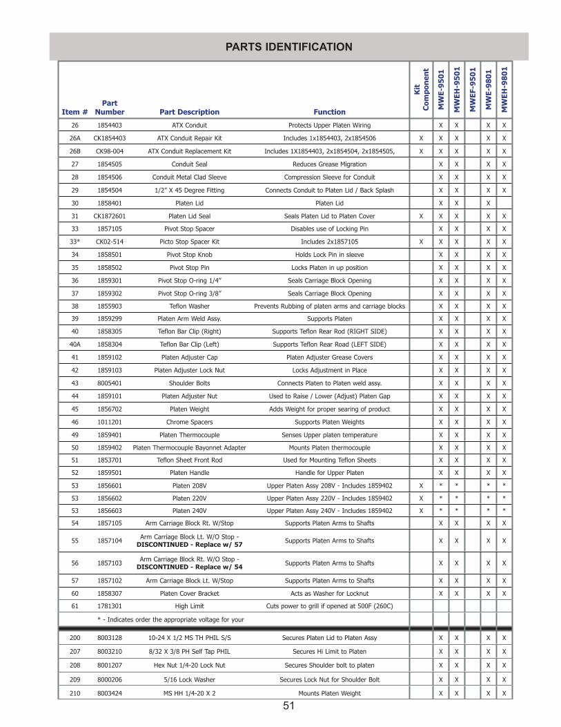
51
PARTS IDENTIFICATION
Item #Part
Number Part Description Function
Kit
C
ompo
nen
t
MW
E-9
50
1
MW
EH-9
50
1
MW
EF-9
50
1
MW
E-9
80
1
MW
EH-9
80
1
26 1854403 ATX Conduit Protects Upper Platen Wiring X X X X
26A CK1854403 ATX Conduit Repair Kit Includes 1x1854403, 2x1854506 X X X X X
26B CK98-004 ATX Conduit Replacement Kit Includes 1X1854403, 2x1854504, 2x1854505, X X X X X
27 1854505 Conduit Seal Reduces Grease Migration X X X X
28 1854506 Conduit Metal Clad Sleeve Compression Sleeve for Conduit X X X X
29 1854504 1/2” X 45 Degree Fitting Connects Conduit to Platen Lid / Back Splash X X X X
30 1858401 Platen Lid Platen Lid X X X
31 CK1872601 Platen Lid Seal Seals Platen Lid to Platen Cover X X X X X
33 1857105 Pivot Stop Spacer Disables use of Locking Pin X X X X
33* CK02-514 Picto Stop Spacer Kit Includes 2x1857105 X X X X X
34 1858501 Pivot Stop Knob Holds Lock Pin in sleeve X X X X
35 1858502 Pivot Stop Pin Locks Platen in up position X X X X
36 1859301 Pivot Stop O-ring 1/4” Seals Carriage Block Opening X X X X
37 1859302 Pivot Stop O-ring 3/8” Seals Carriage Block Opening X X X X
38 1855903 Teflon Washer Prevents Rubbing of platen arms and carriage blocks X X X X
39 1859299 Platen Arm Weld Assy. Supports Platen X X X X
40 1858305 Teflon Bar Clip (Right) Supports Teflon Rear Rod (RIGHT SIDE) X X X X
40A 1858304 Teflon Bar Clip (Left) Supports Teflon Rear Road (LEFT SIDE) X X X X
41 1859102 Platen Adjuster Cap Platen Adjuster Grease Covers X X X X
42 1859103 Platen Adjuster Lock Nut Locks Adjustment in Place X X X X
43 8005401 Shoulder Bolts Connects Platen to Platen weld assy. X X X X
44 1859101 Platen Adjuster Nut Used to Raise / Lower (Adjust) Platen Gap X X X X
45 1856702 Platen Weight Adds Weight for proper searing of product X X X X
46 1011201 Chrome Spacers Supports Platen Weights X X X X
49 1859401 Platen Thermocouple Senses Upper platen temperature X X X X
50 1859402 Platen Thermocouple Bayonnet Adapter Mounts Platen thermocouple X X X X
51 1853701 Teflon Sheet Front Rod Used for Mounting Teflon Sheets X X X X
52 1859501 Platen Handle Handle for Upper Platen X X X X
53 1856601 Platen 208V Upper Platen Assy 208V - Includes 1859402 X * * * *
53 1856602 Platen 220V Upper Platen Assy 220V - Includes 1859402 X * * * *
53 1856603 Platen 240V Upper Platen Assy 240V - Includes 1859402 X * * * *
54 1857105 Arm Carriage Block Rt. W/Stop Supports Platen Arms to Shafts X X X X
55 1857104 Arm Carriage Block Lt. W/O Stop - DISCONTINUED - Replace w/ 57 Supports Platen Arms to Shafts X X X X
56 1857103 Arm Carriage Block Rt. W/O Stop - DISCONTINUED - Replace w/ 54 Supports Platen Arms to Shafts X X X X
57 1857102 Arm Carriage Block Lt. W/Stop Supports Platen Arms to Shafts X X X X
60 1858307 Platen Cover Bracket Acts as Washer for Locknut X X X X
61 1781301 High Limit Cuts power to grill if opened at 500F (260C)
* - Indicates order the appropriate voltage for your
200 8003128 10-24 X 1/2 MS TH PHIL S/S Secures Platen Lid to Platen Assy X X X X
207 8003210 8/32 X 3/8 PH Self Tap PHIL Secures Hi Limit to Platen X X X X
208 8001207 Hex Nut 1/4-20 Lock Nut Secures Shoulder bolt to platen X X X X
209 8000206 5/16 Lock Washer Secures Lock Nut for Shoulder Bolt X X X X
210 8003424 MS HH 1/4-20 X 2 Mounts Platen Weight X X X X
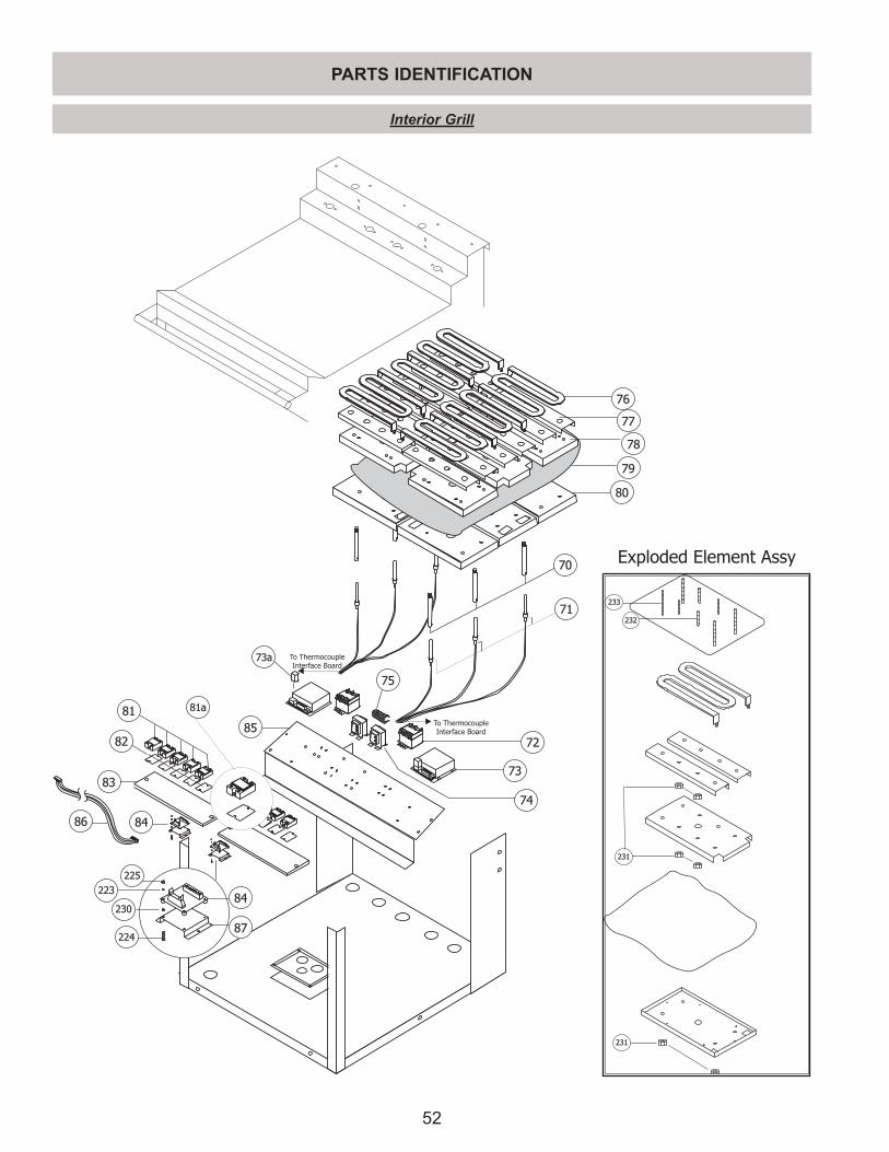
52
PARTS IDENTIFICATION
To ThermocoupleInterface Board
To ThermocoupleInterface Board
70
71
72
73
74
75
76
77
78
79
80
81
82
83
84
85
81a
73a
86
225
223
230
224
84
87
233
232
231
231
Exploded Element Assy
Interior Grill
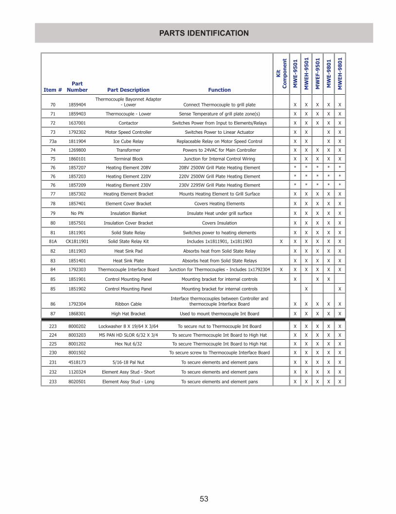
53
PARTS IDENTIFICATION
Item #Part
Number Part Description Function
Kit
C
ompo
nen
t
MW
E-9
50
1
MW
EH-9
50
1
MW
EF-9
50
1
MW
E-9
80
1
MW
EH-9
80
1
70 1859404Thermocouple Bayonnet Adapter
- Lower Connect Thermocouple to grill plate X X X X X
71 1859403 Thermocouple - Lower Sense Temperature of grill plate zone(s) X X X X X
72 1637001 Contactor Switches Power from Input to Elements/Relays X X X X X
73 1792302 Motor Speed Controller Switches Power to Linear Actuator X X X X
73a 1811904 Ice Cube Relay Replaceable Relay on Motor Speed Control X X X X
74 1269800 Transformer Powers to 24VAC for Main Controller X X X X X
75 1860101 Terminal Block Junction for Internal Control Wiring X X X X X
76 1857207 Heating Element 208V 208V 2500W Grill Plate Heating Element * * * * *
76 1857203 Heating Element 220V 220V 2500W Grill Plate Heating Element * * * * *
76 1857209 Heating Element 230V 230V 2295W Grill Plate Heating Element * * * * *
77 1857302 Heating Element Bracket Mounts Heating Element to Grill Surface X X X X X
78 1857401 Element Cover Bracket Covers Heating Elements X X X X X
79 No PN Insulation Blanket Insulate Heat under grill surface X X X X X
80 1857501 Insulation Cover Bracket Covers Insulation X X X X X
81 1811901 Solid State Relay Switches power to heating elements X X X X X
81A CK1811901 Solid State Relay Kit Includes 1x1811901, 1x1811903 X X X X X X
82 1811903 Heat Sink Pad Absorbs heat from Solid State Relay X X X X X
83 1851401 Heat Sink Plate Absorbs heat from Solid State Relays X X X X X
84 1792303 Thermocouple Interface Board Junction for Thermocouples - Includes 1x1792304 X X X X X X
85 1851901 Control Mounting Panel Mounting bracket for internal controls X X X
85 1851902 Control Mounting Panel Mounting bracket for internal controls X X
86 1792304 Ribbon CableInterface thermocouples between Controller and
thermocouple Interface Board X X X X X
87 1868301 High Hat Bracket Used to mount thermocouple Int Board X X X X X
223 8000202 Lockwasher 8 X 19/64 X 3/64 To secure nut to Thermocouple Int Board X X X X X
224 8003203 MS PAN HD SLOR 6/32 X 3/4 To secure Thermocouple Int Board to High Hat X X X X X
225 8001202 Hex Nut 6/32 To secure Thermocouple Int Board to High Hat X X X X X
230 8001502 To secure screw to Thermocouple Interface Board X X X X X
231 4518173 5/16-18 Pal Nut To secure elements and element pans X X X X X
232 1120324 Element Assy Stud - Short To secure elements and element pans X X X X X
233 8020501 Element Assy Stud - Long To secure elements and element pans X X X X X
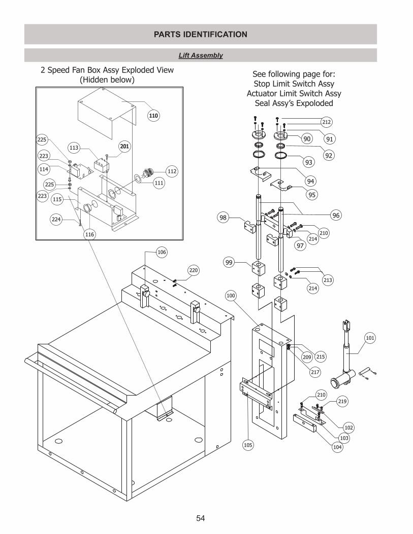
54
PARTS IDENTIFICATION
212
9190
92
93
94
95
210
214
96
97
98
213
214
99
100
215209
217
105
102
103
104
219
210
101
106
220
110110
115
113
111
114
225
223
224
201201
116
223
225
112
2 Speed Fan Box Assy Exploded View (Hidden below)
See following page for:Stop Limit Switch Assy
Actuator Limit Switch AssySeal Assy’s Expoloded
Lift Assembly
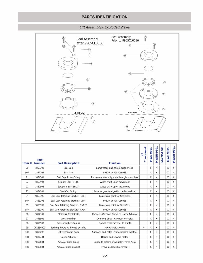
55
PARTS IDENTIFICATION
Seal Assemblyafter 9905CL0056
90
91
212
93
96
92
94
95
Grill Plate
Seal AssemblyPrior to 9905CL0056
96
90A90A
8282
Grill Plate
221
107107
108108
109109
94A
95A
Lift Assembly - Exploded Views
Item #Part
Number Part Description Function
Kit
C
ompo
nen
t
MW
E-9
50
1
MW
EH-9
50
1
MW
EF-9
50
1
MW
E-9
80
1
MW
EH-9
80
1
90 1857703 Seal Cap Compresses and covers scraper seal X X X X
90A 1857702 Seal Cap PRIOR to 9905CL0055 X X X X
91 1874301 Seal Cap Screw O-ring Reduces grease migration through screw hole X X X X
92 1862904 Scraper Seal - FULL Wipes shaft upon movement X X X X
92 1862903 Scraper Seal - SPLIT Wipes shaft upon movement X X X X
93 1874201 Seal Cap O-ring Reduces grease migration under seal cap X X X X
94 1863396 Seal Cap Retaining Bracket - LEFT Fasterning point for Seal Caps X X X X
94A 1863398 Seal Cap Retaining Bracket - LEFT PRIOR to 9905CL0055 X X X X
95 1863397 Seal Cap Retaining Bracket - RIGHT Fasterning point for Seal Caps X X X X
95A 1863399 Seal Cap Retaining Bracket - RIGHT PRIOR to 9905CL0055 X X X X
96 1857101 Stainless Steal Shaft Connects Carriage Blocks to Linear Actuator X X X X
97 1856901 Cross Member Connects Linear Actuator to Shafts X X X X
98 1856902 Cross member Clamps Clamps cross member to shafts X X X X
99 CK1854803 Bushing Blocks w/ bronze bushing Keeps shafts plumb X X X X X
100 1858298 Lift Mechanism Rack Supports and holds lift mechanism together X X X X
101 1812401 Linear Actuator Raises and Lowers Platen X X X X
102 1857001 Actuator Base brace Supports bottom of Actuator Frame Assy X X X X
103 1863601 Actuator Base Bracket Prevents Rack Movement X X X X
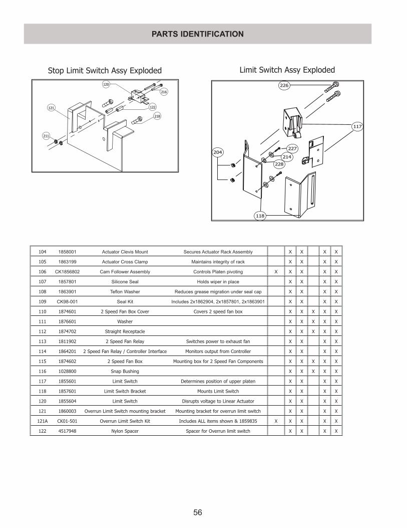
56
PARTS IDENTIFICATION
Stop Limit Switch Assy Exploded
121
120
218
122
216
211
226
117
118
227
214
228
204
Limit Switch Assy Exploded
104 1858001 Actuator Clevis Mount Secures Actuator Rack Assembly X X X X
105 1863199 Actuator Cross Clamp Maintains integrity of rack X X X X
106 CK1856802 Cam Follower Assembly Controls Platen pivoting X X X X X
107 1857801 Silicone Seal Holds wiper in place X X X X
108 1863901 Teflon Washer Reduces grease migration under seal cap X X X X
109 CK98-001 Seal Kit Includes 2x1862904, 2x1857801, 2x1863901 X X X X
110 1874601 2 Speed Fan Box Cover Covers 2 speed fan box X X X X X
111 1876601 Washer X X X X X
112 1874702 Straight Receptacle X X X X X
113 1811902 2 Speed Fan Relay Switches power to exhaust fan X X X X
114 1864201 2 Speed Fan Relay / Controller Interface Monitors output from Controller X X X X
115 1874602 2 Speed Fan Box Mounting box for 2 Speed Fan Components X X X X X
116 1028800 Snap Bushing X X X X X
117 1855601 Limit Switch Determines position of upper platen X X X X
118 1857601 Limit Switch Bracket Mounts Limit Switch X X X X
120 1855604 Limit Switch Disrupts voltage to Linear Actuator X X X X
121 1860003 Overrun Limit Switch mounting bracket Mounting bracket for overrun limit switch X X X X
121A CK01-501 Overrun Limit Switch Kit Includes ALL items shown & 1859835 X X X X X
122 4517948 Nylon Spacer Spacer for Overrun limit switch X X X X
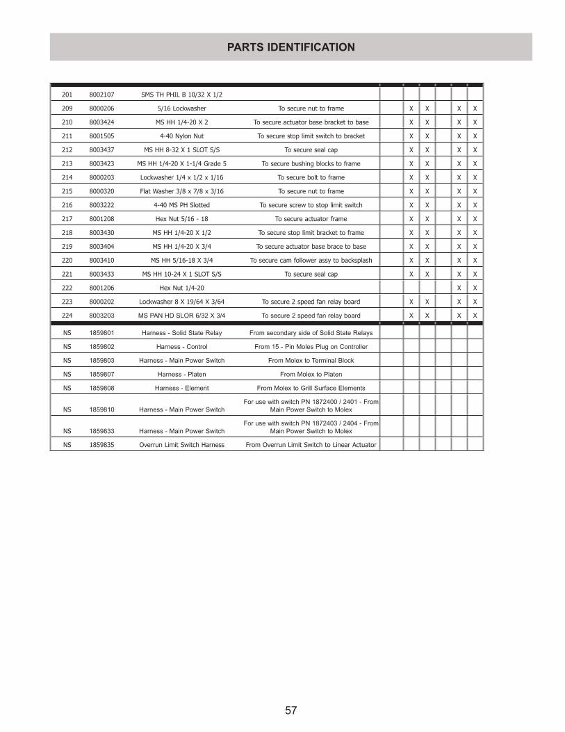
57
PARTS IDENTIFICATION
201 8002107 SMS TH PHIL B 10/32 X 1/2
209 8000206 5/16 Lockwasher To secure nut to frame X X X X
210 8003424 MS HH 1/4-20 X 2 To secure actuator base bracket to base X X X X
211 8001505 4-40 Nylon Nut To secure stop limit switch to bracket X X X X
212 8003437 MS HH 8-32 X 1 SLOT S/S To secure seal cap X X X X
213 8003423 MS HH 1/4-20 X 1-1/4 Grade 5 To secure bushing blocks to frame X X X X
214 8000203 Lockwasher 1/4 x 1/2 x 1/16 To secure bolt to frame X X X X
215 8000320 Flat Washer 3/8 x 7/8 x 3/16 To secure nut to frame X X X X
216 8003222 4-40 MS PH Slotted To secure screw to stop limit switch X X X X
217 8001208 Hex Nut 5/16 - 18 To secure actuator frame X X X X
218 8003430 MS HH 1/4-20 X 1/2 To secure stop limit bracket to frame X X X X
219 8003404 MS HH 1/4-20 X 3/4 To secure actuator base brace to base X X X X
220 8003410 MS HH 5/16-18 X 3/4 To secure cam follower assy to backsplash X X X X
221 8003433 MS HH 10-24 X 1 SLOT S/S To secure seal cap X X X X
222 8001206 Hex Nut 1/4-20 X X
223 8000202 Lockwasher 8 X 19/64 X 3/64 To secure 2 speed fan relay board X X X X
224 8003203 MS PAN HD SLOR 6/32 X 3/4 To secure 2 speed fan relay board X X X X
NS 1859801 Harness - Solid State Relay From secondary side of Solid State Relays
NS 1859802 Harness - Control From 15 - Pin Moles Plug on Controller
NS 1859803 Harness - Main Power Switch From Molex to Terminal Block
NS 1859807 Harness - Platen From Molex to Platen
NS 1859808 Harness - Element From Molex to Grill Surface Elements
NS 1859810 Harness - Main Power SwitchFor use with switch PN 1872400 / 2401 - From
Main Power Switch to Molex
NS 1859833 Harness - Main Power SwitchFor use with switch PN 1872403 / 2404 - From
Main Power Switch to Molex
NS 1859835 Overrun Limit Switch Harness From Overrun Limit Switch to Linear Actuator

58
Eprom Chip
Menu Item Name Function (Duty)
Time (Secs)
Set Temp Set Temp
Gap Setting
Version # (F) (C)
3.01 3.524.00 4.01 4.02
6.20
Low
er
Upp
er
Low
er
Upp
er
YES YES YESYES
OFF (Always first)NONE NONE OFF OFF OFF OFF
.090
6.20 Chip & Higher ---> .083
NO NO NO YES Preheat “Ready to Cook” NONE 350 425 177 218 .083
YES YES YESYES
10:1 - CLAM Remove 36350 425 177 218 .255
6.20 Chip & Higher ---> Toast Buns 0
YES YES YESYES
4:1 - CLAM Remove 104350 425 177 218 .415
6.20 Chip & Higher ---> Toast Buns 0
YES YES YES NO Circular Bacon - CLAM Remove 88 325 400 163 204 .090
NO NO NO YES Strip Bacon - CLAM Remove 23 350 425 177 218 .090
YES YES YES NO Sausage - CLAM (THD) Remove 48 325 400 163 204 .350
YES YES YES YES Sausage - CLAM (FRZ) Remove 82 350 425 177 218 .350
YES YES YES YES McRib - CLAM Remove 163 350 425 177 218 .530
NO NO YES YES Steak - CLAM Remove 82 350 425 177 218 .415
YES YES NO NO Grilled Chicken - FLATTurn 115
350 425 177 218 NONERemove 230
NO NO YES YES Grilled Chicken - FLATTurn 195
350 425 177 218 NONERemove 410
YES YES YES YES Folded Eggs - FLAT Remove 35 265 OFF 130 OFF NONE
YES YES YES NO Canadian Bacon - FLATTurn 10
265 OFF 130 OFF NONERemove 20
YES YES YES YES Round Eggs Remove 150 265 OFF 130 OFF NONE
NO NO NO YES Chick F Bread - FLAT Remove 100 350 425 177 218 NONE
YES YES YES YES 10:1 - FLAT
Sear 20
340 OFF 171 OFF NONETurn 75
Remove 125
YES YES YES YES 4:1 - FLAT
Sear 20
365 OFF 185 OFF NONETurn 150
Remove 270
YES YES YES YES McRib - FLATTurn 270
365 OFF 185 OFF NONERemove 390
CONTROLLER MENU ITEMS
THE FOLLOWING TABLE LISTS MENU ITEMS DEFAULTED IN THE MAIN CONTROLLER AS NEW. TO REPROGRAM ANY FUNCTION OR FEATURE BELOW, SEE PROGRAMMING.
** THE MENU ITEMS LISTED BELOW ARE FOR EPROM CHIP VERSIONS UP TO 6.20 - FOR EPROM CHIP VERSION 7.XX, PLEASE SEE THE FOLLOWING TABLE FOR MORE INFORMATION **
** TO IDENTIFY YOUR EPROM CHIP, PRESS AND HOLD THE PROG BUTTON THE CONTROLLER **
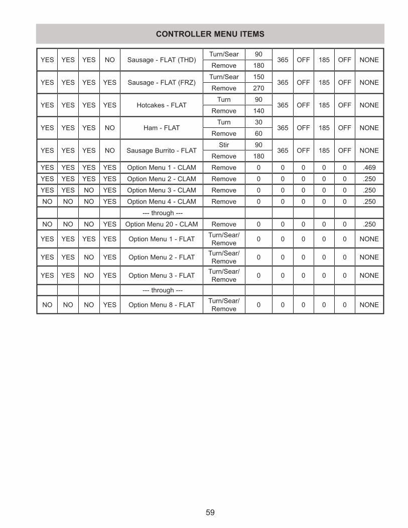
59
YES YES YES NO Sausage - FLAT (THD)Turn/Sear 90
365 OFF 185 OFF NONERemove 180
YES YES YES YES Sausage - FLAT (FRZ)Turn/Sear 150
365 OFF 185 OFF NONERemove 270
YES YES YES YES Hotcakes - FLATTurn 90
365 OFF 185 OFF NONERemove 140
YES YES YES NO Ham - FLATTurn 30
365 OFF 185 OFF NONERemove 60
YES YES YES NO Sausage Burrito - FLATStir 90
365 OFF 185 OFF NONERemove 180
YES YES YES YES Option Menu 1 - CLAM Remove 0 0 0 0 0 .469
YES YES YES YES Option Menu 2 - CLAM Remove 0 0 0 0 0 .250
YES YES NO YES Option Menu 3 - CLAM Remove 0 0 0 0 0 .250
NO NO NO YES Option Menu 4 - CLAM Remove 0 0 0 0 0 .250
--- through ---
NO NO NO YES Option Menu 20 - CLAM Remove 0 0 0 0 0 .250
YES YES YES YES Option Menu 1 - FLAT Turn/Sear/Remove 0 0 0 0 0 NONE
YES YES NO YES Option Menu 2 - FLAT Turn/Sear/Remove 0 0 0 0 0 NONE
YES YES NO YES Option Menu 3 - FLAT Turn/Sear/Remove 0 0 0 0 0 NONE
--- through ---
NO NO NO YES Option Menu 8 - FLAT Turn/Sear/Remove 0 0 0 0 0 NONE
CONTROLLER MENU ITEMS
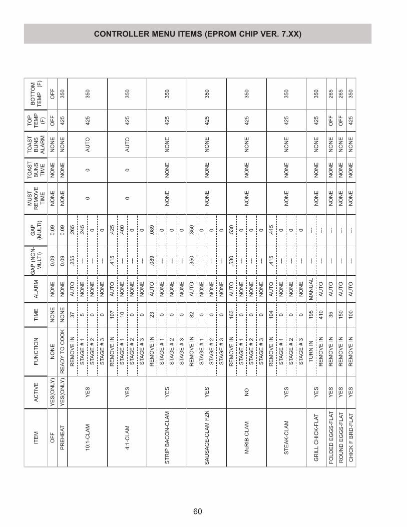
60
ITE
M
AC
TIV
EFU
NC
TIO
NTI
ME
ALA
RM
GA
P (N
ON
-M
ULT
I)G
AP
(M
ULT
I)
MU
ST
RE
MO
VE
TI
ME
TOA
ST
BU
NS
TI
ME
TOA
ST
BU
NS
A
LAR
M
TOP
TEM
P
(F)
BO
TTO
M
TEM
P (
F)
OFF
YE
S(O
NLY
)N
ON
EN
ON
EN
ON
E0.
090.
09N
ON
EN
ON
EN
ON
EO
FFO
FF
PR
EH
EAT
YE
S(O
NLY
)R
EA
DY
TO C
OO
KN
ON
EN
ON
E0.
090.
09N
ON
EN
ON
EN
ON
E42
535
0
10:1
-CLA
MY
ES
RE
MO
VE
IN37
AU
TO.2
55.2
65
00
AU
TO42
535
0S
TAG
E #
15
NO
NE
---
.245
STA
GE
# 2
0N
ON
E--
-0
STA
GE
# 3
0N
ON
E--
-0
4:1-
CLA
MY
ES
RE
MO
VE
IN10
7A
UTO
.415
.425
00
AU
TO42
535
0S
TAG
E #
110
NO
NE
---
.400
STA
GE
# 2
0N
ON
E--
-0
STA
GE
# 3
0N
ON
E--
-0
STR
IP B
AC
ON
-CLA
MY
ES
RE
MO
VE
IN23
AU
TO.0
89.0
89
NO
NE
NO
NE
NO
NE
425
350
STA
GE
# 1
0N
ON
E--
-0
STA
GE
# 2
0N
ON
E--
-0
STA
GE
# 3
0N
ON
E--
-0
SA
US
AG
E-C
LAM
FZN
YE
S
RE
MO
VE
IN82
AU
TO.3
50.3
50
NO
NE
NO
NE
NO
NE
425
350
STA
GE
# 1
0N
ON
E--
-0
STA
GE
# 2
0N
ON
E--
-0
STA
GE
# 3
0N
ON
E--
-0
McR
IB-C
LAM
NO
RE
MO
VE
IN16
3A
UTO
.530
.530
NO
NE
NO
NE
NO
NE
425
350
STA
GE
# 1
0N
ON
E--
-0
STA
GE
# 2
0N
ON
E--
-0
STA
GE
# 3
0N
ON
E--
-0
STE
AK
-CLA
MY
ES
RE
MO
VE
IN10
4A
UTO
.415
.415
NO
NE
NO
NE
NO
NE
425
350
STA
GE
# 1
0N
ON
E--
-0
STA
GE
# 2
0N
ON
E--
-0
STA
GE
# 3
0N
ON
E--
-0
GR
ILL
CH
ICK
-FLA
TY
ES
TUR
N IN
195
MA
NU
AL
---
---
NO
NE
NO
NE
NO
NE
425
350
RE
MO
VE
IN41
0A
UTO
---
---
FOLD
ED
EG
GS
-FLA
TY
ES
RE
MO
VE
IN35
AU
TO--
---
-N
ON
EN
ON
EN
ON
EO
FF26
5
RO
UN
D E
GG
S-F
LAT
YE
SR
EM
OV
E IN
150
AU
TO--
---
-N
ON
EN
ON
EN
ON
EO
FF26
5
CH
ICK
F B
RD
-FLA
TY
ES
RE
MO
VE
IN10
0A
UTO
---
---
NO
NE
NO
NE
NO
NE
425
350
CONTROLLER MENU ITEMS (EPROM CHIP VER. 7.XX)
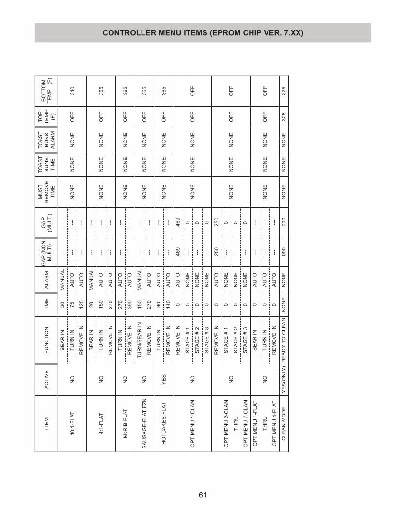
61
ITE
M
AC
TIV
EFU
NC
TIO
NTI
ME
ALA
RM
GA
P (N
ON
-M
ULT
I)G
AP
(M
ULT
I)
MU
ST
RE
MO
VE
TI
ME
TOA
ST
BU
NS
TI
ME
TOA
ST
BU
NS
A
LAR
M
TOP
TEM
P
(F)
BO
TTO
M
TEM
P (
F)
10:1
-FLA
TN
O
SE
AR
IN20
MA
NU
AL
---
---
NO
NE
NO
NE
NO
NE
OFF
340
TUR
N IN
75A
UTO
---
---
RE
MO
VE
IN12
5A
UTO
---
---
4:1-
FLAT
NO
SE
AR
IN20
MA
NU
AL
---
---
NO
NE
NO
NE
NO
NE
OFF
365
TUR
N IN
150
AU
TO--
---
-
RE
MO
VE
IN27
0A
UTO
---
---
McR
IB-F
LAT
NO
TUR
N IN
270
AU
TO--
---
-N
ON
EN
ON
EN
ON
EO
FF36
5R
EM
OV
E IN
390
AU
TO--
---
-
SA
US
AG
E-F
LAT
FZN
NO
TUR
N/S
EA
R IN
150
MA
NU
AL
---
---
NO
NE
NO
NE
NO
NE
OFF
365
RE
MO
VE
IN27
0A
UTO
---
---
HO
TCA
KE
S-F
LAT
YE
STU
RN
IN90
AU
TO--
---
-N
ON
EN
ON
EN
ON
EO
FF36
5R
EM
OV
E IN
140
AU
TO--
---
-
OP
T M
EN
U 1
-CLA
MN
O
RE
MO
VE
IN0
AU
TO.4
69.4
69
NO
NE
NO
NE
NO
NE
OFF
OFF
STA
GE
# 1
0N
ON
E--
-0
STA
GE
# 2
0N
ON
E--
-0
STA
GE
# 3
0N
ON
E--
-0
NO
RE
MO
VE
IN0
AU
TO.2
50.2
50
NO
NE
NO
NE
NO
NE
OFF
OFF
OP
T M
EN
U 2
-CLA
MS
TAG
E #
10
NO
NE
---
0
THR
US
TAG
E #
20
NO
NE
---
0
OP
T M
EN
U 7
-CLA
MS
TAG
E #
30
NO
NE
---
0
OP
T M
EN
U 1
-FLA
T
NO
SE
AR
IN0
AU
TO--
---
-
NO
NE
NO
NE
NO
NE
OFF
OFF
THR
UTU
RN
IN0
AU
TO--
---
-
OP
T M
EN
U 4
-FLA
TR
EM
OV
E IN
0A
UTO
---
---
CLE
AN
MO
DE
YE
S(O
NLY
)R
EA
DY
TO C
LEA
NN
ON
EN
ON
E.0
90.0
90N
ON
EN
ON
EN
ON
E32
532
5
CONTROLLER MENU ITEMS (EPROM CHIP VER. 7.XX)
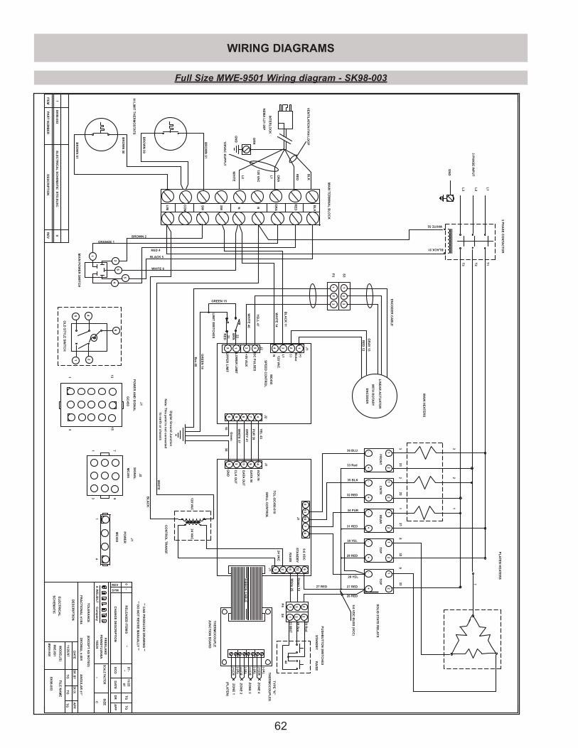
62
4
29 YEL
30 YEL
7
34 PUR
10
35 BLK
13
36 BLU
(-)AL
(+)C
R
(-)AL
(+)C
R
(-)AL
(+)C
R
(+)C
R
(-)AL
TY
PE
"K
"
TH
ER
MO
CO
UP
LE
S
ZO
NE
1
ZO
NE
2
ZO
NE
3
ZO
NE
4
(PL
AT
EN
)
T1T2
T3
L1L2
L3
233 3
222
211
328
339
7
12
GR
AY
13
RE
D12
WH
ITE
46
YE
LL
47
2124
VA
C
612
15
STA
ND
BY
RA
ISE
9.6V
DC
9.6V
DC
BU
SS
(VC
C)
25W
HT
50R
ed
Wh
ite25
Green
12
26 RED
27 RED
49G
rn
44
33 Red
32 RED
31 RED
28 RED
27 RED
OR
A
L1
RE
D
WHITE 6
BLACK 5
RED 4
ORANGE 1
BROWN 2
BR
OW
N51
BR
OW
N51
BL
AC
K11
BL
AC
K
BLACK51
BL
K
BR
OW
N50
BR
OW
N50
*
*0
RE
LE
AS
ED
ITE
M/S
TG
TG
-97-*
97
11/25
SC
HE
MA
TIC
MW
E-9501
11/25
/97T
GT
G
SK
98-003
**D
ON
OT
RE
VIS
EM
AN
UA
LLY
**
**C
AD
PR
OD
UC
ED
DR
AW
ING
**
EL
EC
TR
ICA
L
MW
EH-9501
1E
LE
CT
RIC
AL
SC
HE
MA
TIC
ST
D.E
LE
C.
0
TG
SK
98-003
RE
VD
ES
CR
IPT
ION
PA
RT
NU
MB
ER
ITE
M
WE
LB
ILT
AC
om
pan
y
FR
EE
LA
ND
PE
NN
SY
LVA
NIA
18224
DR.CK.D
R.B
YA
PP.
DA
TE
SC
AL
EFA
CT
OR
SIZ
E
CH
AN
GE
DE
SC
RIP
TIO
NE
CO
DA
TE
DR
AP
P
SYM
REV
FIL
EN
AM
EM
OD
EL
(S)
TO
LE
RA
NC
E(E
XC
EP
TA
SN
OT
ED
)
DE
SC
RIP
TIO
N
FR
AC
TIO
NA
L±1
/64D
EC
IMA
L±.005
AN
GU
LA
R±1°
C
TG
L-G
C450-010
GR
ILL
CO
NT
RO
L J1
J1J1
RIB
BO
NC
AB
LE
1491153
8
TH
ER
MO
CO
UP
LE
JU
NC
TIO
NB
OA
RD
4 3 2 13 5
6 7 J29 8 4
J1
J2Y
EL
43
PU
R39
DA
TA
OU
T
WH
ITE
37
MC
455
SP
EE
DC
ON
TR
OL
AC
KIN
DA
TA
IN
CL
KO
UT
GN
D
GR
EY
41
LIN
EA
RA
CT
UA
TO
R
WIT
HR
OTA
RY
EN
CO
DE
R
12
3 32
1S
3
P3
UP
PE
RL
IMIT
LO
WE
RL
IMIT
2 1
Dig
italG
rou
nd
Jun
ction
No
te:T
his
po
int
isn
ot
con
nected
toearth
or
chassis
GR
EE
N14
GREEN 15
3810
Brn
45
Green
DC
PU
LS
ES
+5V
AU
X
Mo
tor
(+)
(-)N L1120
VA
C
-+
+-
-+
-+
-+
FR
ON
TC
NT
RR
EA
RT
OP
TO
PS
OL
IDS
TA
TE
RE
LA
YS
CO
NT
RO
LT
RA
NS
F.
231
231
P4
S4
STA
ND
BY
RA
ISE
PU
SH
BU
TT
ON
SW
ITC
HE
S
LIM
ITS
WIT
CH
ES
HIL
IMIT
TH
ER
MO
STA
TS
GR
N
GN
DW
HIT
E
3P
HA
SE
INP
UT
BL
K
RE
D
OR
A
NN
SW
SW
CO
M
LIM
MA
INP
OW
ER
SW
ITC
H
MA
INT
ER
MIN
AL
BL
OC
K
INT
ER
LO
CK
NE
MA
L21-20
P
L2
VE
NT
ILA
TIO
NFA
NL
OO
P
120VA
CS
UP
PLY
2221R
ED
BR
N
WH
ITE
14
WH
ITE
WHITE52
J1
PO
WE
RA
ND
SIG
NA
L
13153
1
GC
450
71
93
J2
MC
455
SIG
NA
LJ1
MC
455
PO
WE
R
14
120V
AC
EN
CO
DE
RC
AB
LE
24V
AC
120V
AC
3P
HA
SE
CO
NTA
CT
OR
GN
D
MA
INH
EA
TE
RS
PL
AT
EN
HE
AT
ER
S
12
12
12
12
12
OL
DS
TY
LE
SW
ITC
H
1
26
4
5
6
1 245
Full Size MWE-9501 Wiring diagram - SK98-003
WIRING DIAGRAMS
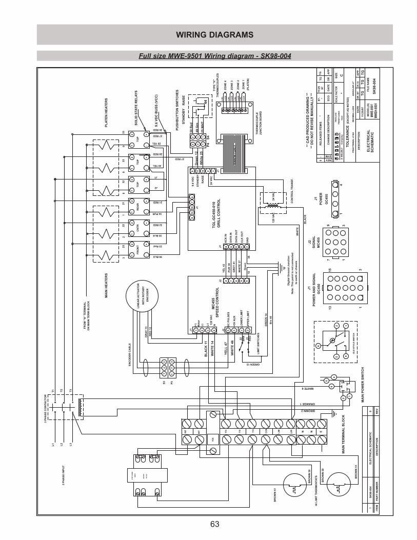
63
WIRING DIAGRAMS
4
29YEL
30YEL
J2
7
34PUR
10
35BLK
GR
AY
13
RE
D12
WH
ITE
46
YE
LL
47
BR
OW
N51
WH
ITE
14
BL
AC
K11
WH
ITE
BL
AC
K
BR
OW
N50
BR
OW
N50
(-)A
L
(+)C
R
(-)A
L
(+)C
R
(-)A
L
(+)C
R
(+)C
R
(-)A
L
TY
PE
"K
"
TH
ER
MO
CO
UP
LE
S
ZO
NE
1
ZO
NE
2
ZO
NE
3
ZO
NE
4
(PL
AT
EN
)
6 12 1525
WH
T
50R
ed
Wh
ite
25
Gre
en12
26RED
27RED
49G
rn
44
33Red
32RED
31RED
28RED
27RED
J1
13
36BLU
2 124
VA
C
ORANGE1
BROWN2
T1
T2
T3
L1
L2
L3
2322
2132
3333
*
*0
RE
LE
AS
ED
ITE
M/S
TG
TG
-97
- *97
11/2
5
SC
HE
MA
TIC
MW
E-9
501
11/2
5/97
TG
TG
SK
98-0
04
**D
ON
OT
RE
VIS
EM
AN
UA
LLY
****
CA
DP
RO
DU
CE
DD
RA
WIN
G**
EL
EC
TR
ICA
L
MW
EH
-950
1
1E
LE
CT
RIC
AL
SC
HE
MA
TIC
0
TG
L-G
C45
0-01
0G
RIL
LC
ON
TR
OL
BR
OW
N51
J1J2
TG
RE
VD
ES
CR
IPT
ION
PA
RT
NU
MB
ER
ITE
M
SK
98-0
04
WE
LB
ILT
AC
om
pan
y
FR
EE
LA
ND
PE
NN
SY
LV
AN
IA
1822
4
DR.C
K.D
R.B
YA
PP.
DA
TE
SC
AL
EFA
CT
OR
SIZ
E
CH
AN
GE
DE
SC
RIP
TIO
NE
CO
DA
TE
DR
AP
P
SYM
REV
FIL
EN
AM
EM
OD
EL
(S)
TO
LE
RA
NC
E(E
XC
EP
TA
SN
OT
ED
)
DE
SC
RIP
TIO
N
FR
AC
TIO
NA
L±1
/64
DE
CIM
AL
±.00
5A
NG
UL
AR
±1°
C
J1
J1J1
RIB
BO
NC
AB
LE
14 9 11 5 3
8
TH
ER
MO
CO
UP
LE
JUN
CT
ION
BO
AR
D
4321 35
67J2 984
J1 J2Y
EL
43
PU
R39
DA
TA
OU
T
WH
ITE
37
MC
455
SP
EE
DC
ON
TR
OL
AC
KIN
DA
TA
IN
CL
KO
UT
GN
D
GR
EY
41
LIN
EA
RA
CT
UA
TO
R
WIT
HR
OTA
RY
EN
CO
DE
R
12
332
1S
3
P3
UP
PE
RL
IMIT
LO
WE
RL
IMIT
21
Dig
ital
Gro
un
dJu
nct
ion
No
te:
Th
isp
oin
tis
no
tco
nn
ecte
d
toea
rth
or
chas
sis
GR
EE
N14
GREEN15
3810
Brn
45
Gre
en
DC
PU
LS
ES
+5V
AU
X
Mo
tor
(+)
(-)
NL1 12
0V
AC
-+
+-
-+
-+
-+
STA
ND
BY
RA
ISE
9.6
VD
C
FR
ON
TC
NT
RR
EA
RT
OP
TO
PS
OL
IDS
TA
TE
RE
LA
YS
CO
NT
RO
LT
RA
NS
F.
9.6
VD
CB
US
S(V
CC
)
2 3 1
2 3 1
P4
S4
STA
ND
BY
RA
ISE
PU
SH
BU
TT
ON
SW
ITC
HE
S
LIM
ITS
WIT
CH
ES
HIL
IMIT
TH
ER
MO
STA
TS
3P
HA
SE
INP
UT
INT
INT
115
115
CO
M
LIM
MA
INP
OW
ER
SW
ITC
H
MA
INT
ER
MIN
AL
BL
OC
K
22 21R
ED
BR
N
WHITE6
PO
WE
RA
ND
SIG
NA
L
1315 3
1
GC
450
7 1
9 3
MC
455
SIG
NA
LJ1
GC
455
PO
WE
R
14
EN
CO
DE
RC
AB
LE
24V
AC
120
VA
C
3P
HA
SE
CO
NTA
CT
OR
MA
INH
EA
TE
RS
12
12
12
12
12
32
18
9
TO
P
-1
+2
9
N ELIM11
5
15A
PL
AT
EN
HE
AT
ER
S
N
FR
OM
"N
"T
ER
MIN
AL
ON
MA
INT
ER
MB
LO
CK
ST
EP
DO
WN
110/
120
220/
240
XM
FR
OL
DS
TY
LE
SW
ITC
H
1
2
64
5
45
6
12
Full size MWE-9501 Wiring diagram - SK98-004
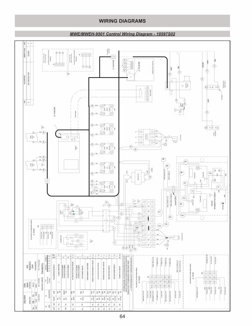
64
WIRING DIAGRAMS
*** CAD PRO
DU
CED D
RAWIN
G - D
O N
OT REVISE M
ANU
ALLY ***
AND SHALL NOT BE COPIED OR REPRODUCED WITHOUT THEIR WRITTEN PERMISSION.THESE DRAWINGS AND SPECIFICATIONS ARE THE PROPERTY OF GARLAND COMMERCIAL INDUSTRIES
19
99
GA
RL
AN
D C
OM
ME
RC
IAL
IND
US
TR
IES
C
REVD
ESCRIPTIO
NPA
RT NU
MB
ERITEM
WELB
ILTA
Co
mp
any
FREELAN
D
PENN
SYLV
AN
IA
18224
DR. CK.D
R. BYA
PP.D
ATE
SCALE FACTOR
SIZE
CH
AN
GE D
ESCRIPTIO
NEC
OD
ATE
DR
APP
SYM
REV
FILE NA
ME
MO
DEL(S)
TOLERA
NC
E(EX
CEPT A
S NO
TED)
DESC
RIPTION
FRAC
TION
AL ±
1/64D
ECIM
AL ±
.005A
NG
ULA
R ±1˚
21
14
22
15
13
12
1213
1114
51
52
23
24
4844
4450
49
4
5 6
2
1
51
1114
5264
1
5
1411
51
3633
3534
3231
3028
3029
27
26
51 2116
14
521
45
52
6
25
14
5
44
EMERG
. STOP
NC
NO
SWITC
H
CO
M
12C
12b
1
10
RELEASED
ITEM/S
TGTG
-95-205
962/7
W/D
CO
NTRO
LSTD
9501M
WE-
2/7/96TG
BG
TG
12
(-)43(+
)
OU
TPUT
INPU
T
P1
J4J3
SWITC
H
GREEN
PB1
BLA
CK
SWITC
H
PB2
INPU
T(-)4
3(+)
OU
TPUT
12
3(+)
INPU
T(-)4
OU
TPUT
12
INPU
T(-)4
3(+)
OU
TPUT
12
INPU
T(-)4
3(+)
OU
TPUT
12
87
56
42
31
J2
J1
PWR SW
MA
IN
FRON
TC
ENTER
REAR
TOP
TOP
LOW
ER LIMIT
SWITC
H
LIMIT SW
ITCH
ES
PLATEN
UPPER
CO
NTRO
LN
CC
BLK
REDN
L1
J2
24
3
J2
1
NC
C G
RILL MO
TOR C
ON
TROL
LINEA
R
AC
TUA
TOR
+-
CO
NTA
CTO
R
T1T2
T3
XY
Z
1W
/D C
ON
TROL STD
9
2
NEM
A 15-50P
RED
WHT
BLK
GRN
ORA
BLUE
RED
BLK
RED
PUR
RED
YEL
RED
YEL
YEL
RED
RED
WHT
RED
GRN
RED
RED
ENC
OD
ER
CO
NN
ECTO
R
GN
DG
RN
HO
OD
INTERLO
CK
RIBB
ON
CA
BLE
SENSO
R CA
RD
CO
NTRO
L XM
FR
7
J1
P2
SSR1SSR2
SSR4SSR3
SSR5
896
541
23
#41 TO P1 #11
#47 TO P3 #2
#37 TO P1 #5
#45 TO P3 #1
#46 TO P3 #3
#21 TO U
PPER LIMIT
#39 TO P1 #9
#43 TO P1 #14
#22 TO K
NEE SW
DETA
IL "A"
S3P3
1 2 3
DETA
IL "C"
P2
P3
#47 TO P2 #5
#38 TO P1 #3
#46 TO P2 #3
#45 TO P2 #6
DETA
IL "B"
#29 TO SSR5 (-)4
#24 TO C
TRL XM
FR1P1 4
#23 TO C
TRL XM
FR
#27 TO SSR5 (+
)3
#14 TO U
PPER LIMIT
32 5
6
#34 TO SSR3 (-)4
7#39 TO
P2 #78
9
SEE DETA
IL "C"
SEE DETA
IL "B"
1413
15#25 TO
SWITC
H PB
1#36 TO
SSR1 (-)4
#12 TO SW
ITCH
PB2
1211
10#35 TO
SSR2 (-)4
#43 TO P2 #4
#41 TO P2 #8
#37 TO P2 #9
#38 TO P3 #1
VIEW
ED FRO
M REA
R OF C
ON
NEC
TOR
VIEW
ED FRO
M REA
R OF C
ON
NEC
TOR
VIEW
ED FRO
M REA
R OF C
ON
NEC
TOR
CO
M
NC
NO
CO
M
NC
NO
WH
T
YEL
YEL
BRN
WH
T
SEE DETA
IL "A"
GREY
RED
BRO
WN
GRA
Y
RED
WH
ITEB
LAC
K
ORA
NG
E
RED
BLK
WHITE
SWC
OM
LIM
18597S02
1859702
P4S4
P5
S512
45
6
26
4
5 5
GRA
Y
SWN
1
WH
ITE
BLA
CK
WIRE N
O 49 W
AS 12
WIRE N
O 50 W
AS 26
BG
TG96
4/8205R1
96-
A
1
BW
IRE NO
48 WA
S 25
AB
E
BLACK
BLACK
WHITEWHITE
WHITE
C
P4
P4 DETA
IL
VIEW
ED FRO
M REA
R OF C
ON
NEC
TOR
AM
P 207360-1 PLUG
AM
P 1-66105-7 SOC
KET
25
26 12
1 2 3
TGTG
8/2896
96-093
AD
DED
DETA
ILS S4 AN
D P4
D3
D
AM
P 207359-1 SOC
KET
AM
P 1-66103-6 PIN
VIEW
ED FRO
M REA
R OF C
ON
NEC
TOR
S4 DETA
IL
1S4 2 3
48 50 49
97-095
5/1897
TGTG
E F G
4
WIRE N
O 13 W
AS 19
WIRE N
O 12 W
AS 18
AD
DED
WIRE N
O.52
REMO
VED
JUM
PER WIRES
OTTO
SWITC
H
AD
DED
ALTERN
ATE SW
ITCH W
IRING
H5
97-254
12/1097
TGTG
H
Moved xfrm
r wires from
sw6
I20298-
6/998TG
TG
I
3
#6 TO LEFT IN
T. CA
RD
#4 TO RIG
HT IN
T. CA
RD
7J
AD
DED
2 SPD FA
N IN
TERFACE
99-588
009/29
TGTG
TO SSR5 #3 LEFT
TO P1 #8 LEFT SID
E
RED
CO
IL
120 VA
C N
120 VA
C L1
5
6
5
6
- + NO
2
NC
7
1
TO SSR5 #3 RIG
HT SID
E
TO P1 #8 RIG
HT SID
E
6 WIRE H
ARN
ESS
1
4
24
3
2
3
GRN120 V
AC
L1
SW
SW
7C
OM
BLK
120 VA
C N
+ -
GRO
UN
D
J
2 SPEED FA
N IN
TERFAC
E
OPTIO
N
8k
AD
DED
GRO
UN
D W
IRE11/19
00-538
00TG
TG
K
9L
AD
DED
EMERG
STOP SW
50301-
01/1002
TGTG
L
NO
TE:
LAM
P TERMS
OPPO
SITE LENS
10M
AD
DED
15A. SW
ITCH54402-
07/1002
TGTG
M
UPPER LIM
IT
~~
~
C
MWE/MWEH-9501 Control Wiring Diagram - 18597S02

65
WIRING DIAGRAMS
REV
DES
CRI
PTIO
NPA
RT N
UM
BER
ITEM
WEL
BIL
TA
Co
mp
any
FREE
LAN
D
PEN
NSY
LVA
NIA
1822
4
DR. C
K.D
R. B
YA
PP.
DA
TE
SCAL
E FA
CTO
RSI
ZE
CH
AN
GE
DES
CRI
PTIO
NEC
OD
ATE
DR
APP
SYM
REV
FILE
NA
ME
MO
DEL
(S)
TOLE
RAN
CE
(EX
CEP
T A
S N
OTE
D)
DES
CRI
PTIO
N
FRA
CTI
ON
AL
±1/
64D
ECIM
AL
±.0
05A
NG
ULA
R ±
1˚
WEL
BIL
TA
Co
mp
any
FREE
LAN
D
PEN
NSY
LVA
NIA
1822
4
DR. C
K.D
R. B
YA
PP.
DA
TE
SCAL
E FA
CTO
RSI
ZE
CH
AN
GE
DES
CRI
PTIO
NEC
OD
ATE
DR
APP
SYM
REV
FILE
NA
ME
MO
DEL
(S)
TOLE
RAN
CE
(EX
CEP
T A
S N
OTE
D)
DES
CRI
PTIO
N
FRA
CTI
ON
AL
±1/
64D
ECIM
AL
±.0
05A
NG
ULA
R ±
1˚
2223
217
3233
3332
722
2321
87 9
50
51
8 97
9
8
51
5050
51
1 2 3
1
2
1
1
2
3
2
3
3
323
222
121
832
933
323
222
121
832
933
1
10
RELE
ASE
D IT
EM/S
TGTG
-95
-20
595
9/14
W/D
ELEM
ENT
STD
FULL
SIZ
E95
01M
WE-
9/14
/95
TGB
GTG
1859
7S01
12
(-)4
3(+
)
OU
TPU
T
INPU
TIN
PUT
(-)4
3(+
)
OU
TPU
T1
2
3(+
)IN
PUT
(-)4
OU
TPU
T1
2
INPU
T(-
)43(
+)
OU
TPU
T1
2
INPU
T(-
)43(
+)
OU
TPU
T1
2
FRO
NT
CEN
TER
REA
RTO
PTO
P
XY
Z T3T2
T1
CO
NTA
CTO
RC
ON
TAC
TOR
T1T2
T3
XY
Z
1859
701
1W
/D E
LEM
ENT
STD
FU
LL S
IZE
0
2
INPU
T
CEN
TER
OU
TPU
T
3(+
)2
INPU
T
FRO
NT
OU
TPU
T
(-)41
(-)41
(-)4
3(+
)21
OU
TPU
T
INPU
T
REA
R
3(+
)2
INPU
T
TOP
OU
TPU
T
3(+
)
OU
TPU
T
(-)41
INPU
T
TOP
2
(-)41
3(+
)2
ELEM
ENT
1
HI-
LIM
IT
LEFT
PLA
TEN
TO
P V
IEW
RIG
HT
PLA
TEN
TO
P V
IEW
XY
ZX
YZ
208
220
NO
MIN
AL
AM
PERE
S PE
R LI
NE
PER
CO
RD
TH
REE
PHA
SE 6
0 H
ZTO
TAL
KW
X-Y
Y-Z
X-Z
THRE
E PH
ASE
KW
/PH
ASE
/CO
RD
21.2
7.06
7.06
7.06
29.5
27.9
--
THIS
APP
LIA
NC
E H
AS
TWO
PO
WER
SU
PPLY
CO
RDS
AN
D O
NE
HO
OD
INTE
RLO
CK
SU
PPLY
CO
RDS
SSR1
SSR2
SSR3
SSR4
SSR5
SSR1
SSR2
SSR3
SSR4
SSR5
CO
MLI
MSW
SW
ELEM
ENT
3
HI-
LIM
IT
ELEM
ENT
2
ELEM
ENT
1
ELEM
ENT
2
ELEM
ENT
3
0RE
LEA
SED
ITEM
/S__
-95
-95
BG
__
** D
O N
OT
REV
ISE
MA
NU
ALL
Y *
***
CA
D P
ROD
UC
ED D
RAW
ING
**
SEE
INFO
RMA
TIO
ND
RAFT
ER
*
PHA
NTO
M
FLA
T
ASS
EMB
LY
FRO
NT
ELRM
ENT
CEN
TER
ELEM
ENT
REA
R EL
EMEN
TRE
AR
ELEM
ENT
CEN
TER
ELEM
ENT
FRO
NT
ELEM
ENT
ERE
DO
RL1
NN
1A
RED
RAW
N W
ITH
CH
AN
GE
95-
062
96-
5/15 9596
__TG
TG
A
XY
Z
25.5
240
29.5
29.5
27.9
27.9
25.5
25.5
2B
REV
ISED
LO
AD
ING
CH
ART
96-
095
97-
5/18 9697
TG__TG
B
C
MWE-9501 Element Wiring Diagram - 18597S01
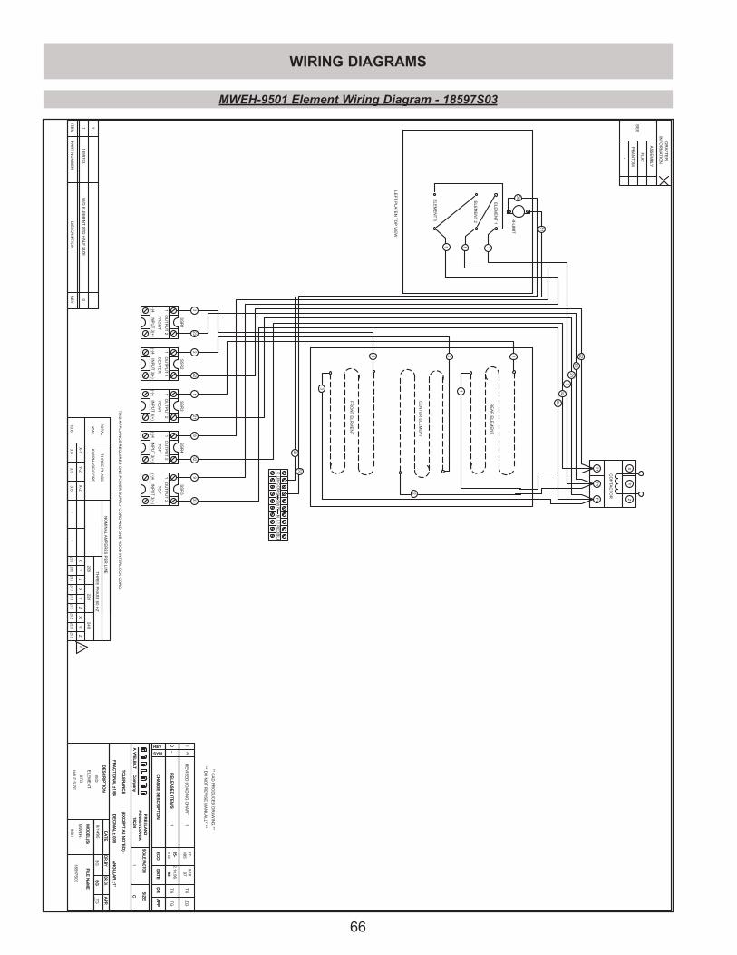
66
WIRING DIAGRAMS
RE
VD
ES
CR
IPT
ION
PA
RT
NU
MB
ER
ITE
M
WE
LB
ILT
AC
om
pany
FR
EE
LA
ND
PE
NN
SY
LV
AN
IA
18224
DR.CK.D
R.
BY
AP
P.
DA
TE
SC
ALE
FAC
TO
RS
IZE
CH
AN
GE
DE
SC
RIP
TIO
NE
CO
DA
TE
DR
AP
P
SYM
REV
FIL
EN
AM
EM
OD
EL(S
)
TO
LE
RA
NC
E(E
XC
EP
TA
SN
OT
ED
)
DE
SC
RIP
TIO
N
FR
AC
TIO
NA
L±1/6
4D
EC
IMA
L±.0
05
AN
GU
LA
R±1°
WE
LB
ILT
AC
om
pany
FR
EE
LA
ND
PE
NN
SY
LV
AN
IA
18224
DR.CK.D
R.
BY
AP
P.
DA
TE
SC
ALE
FAC
TO
RS
IZE
CH
AN
GE
DE
SC
RIP
TIO
NE
CO
DA
TE
DR
AP
P
SYM
REV
FIL
EN
AM
EM
OD
EL(S
)
TO
LE
RA
NC
E(E
XC
EP
TA
SN
OT
ED
)
DE
SC
RIP
TIO
N
FR
AC
TIO
NA
L±1/6
4D
EC
IMA
L±.0
05
AN
GU
LA
R±1°
1
10
RE
LE
AS
ED
ITE
M/S
TG
TG
-95-
015
95
2.1
0.9
6
W/D
ELE
ME
NT
ST
D
HA
LF
SIZ
E9501
MW
EH
-
9/1
4/9
5B
GB
GT
G
18597S
03
12
(-)43(+
)
OU
TP
UT
INP
UT
INP
UT
(-)43(+
)
OU
TP
UT
12
3(+
)IN
PU
T(-)4
OU
TP
UT
12
INP
UT
(-)43(+
)
OU
TP
UT
12
INP
UT
(-)43(+
)
OU
TP
UT
12
FR
ON
TC
EN
TE
RR
EA
RT
OP
TO
P
CO
NTA
CT
OR
T1
T2
T3
XY
Z
1859703
1W
/DE
LE
ME
NT
ST
DH
ALF
SIZ
E0
2
23
32
22
121
832
933
3 2 1
ELE
ME
NT
1
9 7
HI-L
IMIT
LE
FT
PLA
TE
NT
OP
VIE
W
22
23
21
7
32
33
XY
ZX
YZ
208
220
NO
MIN
AL
AM
PE
RE
SP
ER
LIN
ETH
RE
EP
HA
SE
60
HZ
TO
TA
L
KW
X-Y
Y-Z
X-Z
TH
RE
EP
HA
SE
KW
/PH
AS
E/C
OR
D
10.6
3.5
29.527.9
--
SS
R1
SS
R2
SS
R3
SS
R4
SS
R5
8
ELE
ME
NT
2
ELE
ME
NT
3
51
50
51
50
1
2
3
0R
ELE
AS
ED
ITE
M/S
__
-95-
95
BG
__
**D
ON
OT
RE
VIS
EM
AN
UA
LLY
**
**C
AD
PR
OD
UC
ED
DR
AW
ING
**
SE
E
INF
OR
MA
TIO
N
DR
AF
TE
R*
PH
AN
TO
M
FLA
T
AS
SE
MB
LY
FR
ON
TE
LR
ME
NT
CE
NT
ER
ELE
ME
NT
RE
AR
ELE
ME
NT
ELIM
CO
MS
WR
ED
SW
NN
L1
BLK
3.5
3.5
29.529.5
240
XY
Z
25.525.5
25.527.9
27.9
RE
VIS
ED
LO
AD
ING
CH
AR
TA
11
5/1
8
095
97-
97
__TG
TG
A
TH
ISA
PP
LIA
NC
ER
EQ
UIR
ES
ON
EP
OW
ER
SU
PP
LY
CO
RD
AN
DO
NE
HO
OD
INT
ER
LO
CK
CO
RD
CC
MWEH-9501 Element Wiring Diagram - 18597S03
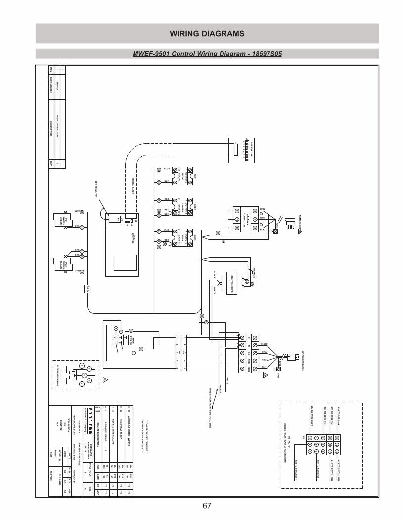
67
WIRING DIAGRAMS
RE
VD
ES
CR
IPT
ION
PA
RT
NU
MB
ER
ITE
M
WE
LB
ILT
AC
om
pan
y
FR
EE
LA
ND
PE
NN
SY
LVA
NIA
18224
DR.CK.D
R.B
YA
PP.
DA
TE
SC
AL
EFA
CT
OR
SIZ
E
CH
AN
GE
DE
SC
RIP
TIO
NE
CO
DA
TE
DR
AP
P
SYM
REV
FIL
EN
AM
EM
OD
EL
(S)
TO
LE
RA
NC
E(E
XC
EP
TA
SN
OT
ED
)
DE
SC
RIP
TIO
N
FR
AC
TIO
NA
L±1
/64D
EC
IMA
L±.005
AN
GU
LA
R±1°
1
10
RE
LE
AS
ED
ITE
M/S
TG
TG
-96-
03396
3/4
W/D
CO
NT
RO
L
FL
AT
9501
MW
EF
-
3/4
/96T
GB
GT
G
**D
ON
OT
RE
VIS
EM
AN
UA
LLY
**
**C
AD
PR
OD
UC
ED
DR
AW
ING
**
12
(-)43(+
)
OU
TP
UT
INP
UT
P1
J4J3
SW
ITC
HG
RE
EN
PB
1
BL
AC
KS
WIT
CH
PB
2
INP
UT
(-)43(+
)
OU
TP
UT
12
3(+
)IN
PU
T(-)4
OU
TP
UT
12
87
56
42
31
J2
J1
654
21
PW
RS
WM
AIN
FR
ON
TC
EN
TE
RR
EA
R
CO
NT
RO
LN
CC
BL
KR
ED
NL
1
J2
CO
NTA
CT
OR
T1
T2
T3
XY
Z
1W
/DC
ON
TR
OL
FL
AT
3
2
NE
MA
15-60P
RED
WHT
BLK
GR
N
ORA
2
1
3633
BLUE
RED
BLK3533
32 RED
RED
3432
PUR
RED
25WHT
RED 44
GRN 12
RED 44
RED 26
GN
DG
RN
HO
OD
INT
ER
LO
CK
RIB
BO
NC
AB
LE
SE
NS
OR
CA
RD
CO
NT
RO
LX
MF
R
J1
SS
R1
SS
R2
SS
R3
DE
TA
IL"B
"
#24T
OC
TR
LX
MF
R1
P1 4
#23T
OC
TR
LX
MF
R
#27T
OS
SR
3(+
)3
32 5
6
#34T
OS
SR
3(-)4
78
9
SE
ED
ETA
IL"B
"
1413
15#25
TO
SW
ITC
HP
B1
#36T
OS
SR
1(-)4
#12T
OS
WIT
CH
PB
212
1110
#35T
OS
SR
2(-)4V
IEW
ED
FR
OM
RE
AR
OF
CO
NN
EC
TO
R
4
5 6
WH
ITE
BL
AC
K
23
24
OR
AN
GE
RED
BLK
WHITE
52
52
51
51
18597S
05
1859705
P4
S4
P5
S51
24
56
26
4
5 5
S1
WH
ITE
BL
AC
K
WIR
ES
FR
OM
RIG
HT
SID
E(F
UL
LS
IZE
)
26
27
1
1A
96-
06296
5/23
JS
TG
RE
VIS
ED
WIR
EC
OL
OR
S
A
B
2B
15-60P
WA
S15-50
P095
97-5/1897
TG
TG
ALT
ER
NA
TE
WIR
ING
1
2
64
5
3C
AD
DE
DA
LT
SW
ITC
HW
IRIN
G97-
254
12/10
97T
GT
G
C
~~
~
C
MWEF-9501 Control Wiring Diagram - 18597S05
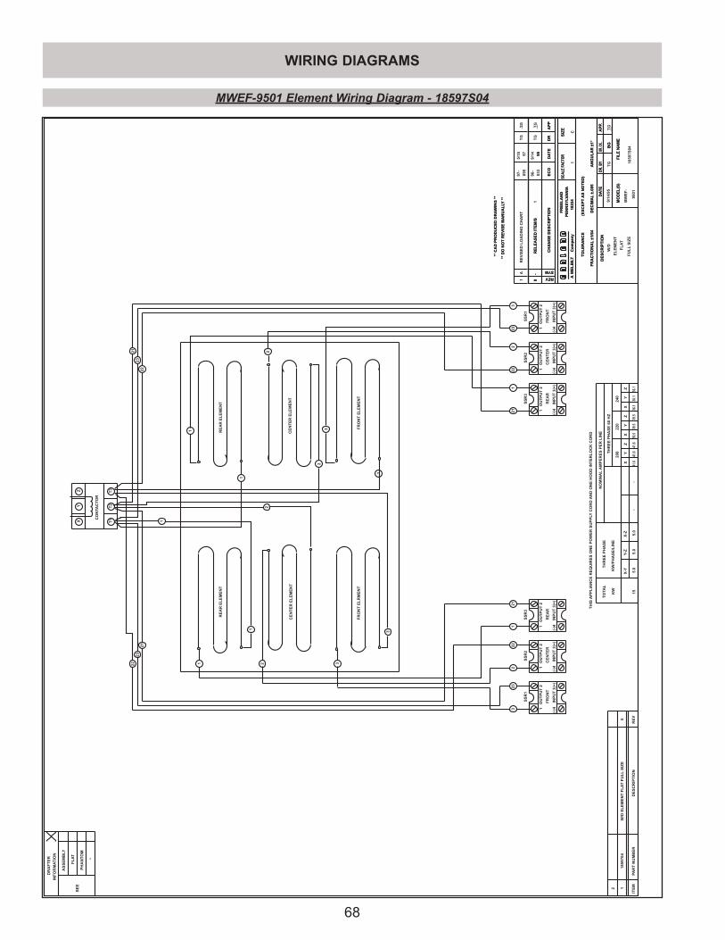
68
WIRING DIAGRAMS
RE
VD
ES
CR
IPT
ION
PA
RT
NU
MB
ER
ITE
M
WE
LB
ILT
AC
om
pan
y
FR
EE
LA
ND
PE
NN
SY
LV
AN
IA18
224
DR.C
K.D
R.B
YA
PP.
DA
TE
SC
AL
EFA
CT
OR
SIZ
E
CH
AN
GE
DE
SC
RIP
TIO
NE
CO
DA
TE
DR
AP
P
SYM
REV
FIL
EN
AM
EM
OD
EL
(S)
TO
LE
RA
NC
E(E
XC
EP
TA
SN
OT
ED
)
DE
SC
RIP
TIO
N
FR
AC
TIO
NA
L±1
/64
DE
CIM
AL
±.00
5A
NG
UL
AR
±1°
WE
LB
ILT
AC
om
pan
y
FR
EE
LA
ND
PE
NN
SY
LV
AN
IA18
224
DR.C
K.D
R.B
YA
PP.
DA
TE
SC
AL
EFA
CT
OR
SIZ
E
CH
AN
GE
DE
SC
RIP
TIO
NE
CO
DA
TE
DR
AP
P
SYM
REV
FIL
EN
AM
EM
OD
EL
(S)
TO
LE
RA
NC
E(E
XC
EP
TA
SN
OT
ED
)
DE
SC
RIP
TIO
N
FR
AC
TIO
NA
L±1
/64
DE
CIM
AL
±.00
5A
NG
UL
AR
±1°
1
10
RE
LE
AS
ED
ITE
M/S
TG
TG
-03
395
9/14
W/D
EL
EM
EN
T
FL
AT
FU
LL
SIZ
E95
01
MW
EF
-
9/14
/95
TG
BG
TG
1859
7S04
**D
ON
OT
RE
VIS
EM
AN
UA
LLY
**
**C
AD
PR
OD
UC
ED
DR
AW
ING
**
12
(-)4
3(+
)
OU
TP
UT
INP
UT
INP
UT
(-)4
3(+
)
OU
TP
UT
12
3(+
)IN
PU
T(-
)4
OU
TP
UT
12
FR
ON
TC
EN
TE
RR
EA
R
CO
NTA
CT
OR
T1
T2
T3
XY
Z
1859
704
1W
/DE
LE
ME
NT
FL
AT
FU
LL
SIZ
E0
2
INP
UT
CE
NT
ER
OU
TP
UT
3(+
)
2
INP
UT
FR
ON
T
OU
TP
UT
(-)41
(-)41
(-)4
3(+
)
21
OU
TP
UT
INP
UT
RE
AR
3(+
)
2
233
222
121
211
222
233
3212223
21
21
2223
XY
ZX
YZ
208
220
NO
MIN
AL
AM
PE
RE
SP
ER
LIN
E
TH
RE
EP
HA
SE
60H
ZT
OTA
L
KW
X-Y
Y-Z
X-Z
TH
RE
EP
HA
SE
KW
/PH
AS
E/L
INE
155.
05.
05.
041
.639
.5-
-
SS
R1
SS
R2
SS
R3
SS
R1
SS
R2
SS
R3
1
2
3
1
1
2
2
3
3
0R
EL
EA
SE
DIT
EM
/S__
-96
-
95
BG
__
**D
ON
OT
RE
VIS
EM
AN
UA
LLY
**
**C
AD
PR
OD
UC
ED
DR
AW
ING
**
SE
E
INF
OR
MA
TIO
N
DR
AF
TE
R *
PH
AN
TO
M
FL
AT
AS
SE
MB
LY
FR
ON
TE
LR
ME
NT
CE
NT
ER
EL
EM
EN
T
RE
AR
EL
EM
EN
TR
EA
RE
LE
ME
NT
CE
NT
ER
EL
EM
EN
T
FR
ON
TE
LE
ME
NT
1
XY
Z
36.1
240
41.6
41.6
39.5
39.5
36.1
36.1
TH
ISA
PP
LIA
NC
ER
EQ
UIR
ES
ON
EP
OW
ER
SU
PP
LY
CO
RD
AN
DO
NE
HO
OD
INT
ER
LO
CK
CO
RD
1A
RE
VIS
ED
LO
AD
ING
CH
AR
T97
-
095
5/18 97
__ TG
TG
C
MWEF-9501 Element Wiring Diagram - 18597S04
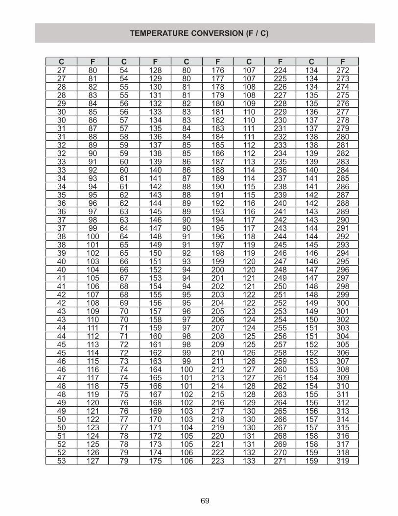
69
C F C F C F C F C F27 80 54 128 80 176 107 224 134 27227 81 54 129 80 177 107 225 134 27328 82 55 130 81 178 108 226 134 27428 83 55 131 81 179 108 227 135 27529 84 56 132 82 180 109 228 135 27630 85 56 133 83 181 110 229 136 27730 86 57 134 83 182 110 230 137 27831 87 57 135 84 183 111 231 137 27931 88 58 136 84 184 111 232 138 28032 89 59 137 85 185 112 233 138 28132 90 59 138 85 186 112 234 139 28233 91 60 139 86 187 113 235 139 28333 92 60 140 86 188 114 236 140 28434 93 61 141 87 189 114 237 141 28534 94 61 142 88 190 115 238 141 28635 95 62 143 88 191 115 239 142 28736 96 62 144 89 192 116 240 142 28836 97 63 145 89 193 116 241 143 28937 98 63 146 90 194 117 242 143 29037 99 64 147 90 195 117 243 144 29138 100 64 148 91 196 118 244 144 29238 101 65 149 91 197 119 245 145 29339 102 65 150 92 198 119 246 146 29440 103 66 151 93 199 120 247 146 29540 104 66 152 94 200 120 248 147 29641 105 67 153 94 201 121 249 147 29741 106 68 154 94 202 121 250 148 29842 107 68 155 95 203 122 251 148 29942 108 69 156 95 204 122 252 149 30043 109 70 157 96 205 123 253 149 30143 110 70 158 97 206 124 254 150 30244 111 71 159 97 207 124 255 151 30344 112 71 160 98 208 125 256 151 30445 113 72 161 98 209 125 257 152 30545 114 72 162 99 210 126 258 152 30646 115 73 163 99 211 126 259 153 30746 116 74 164 100 212 127 260 153 30847 117 74 165 101 213 127 261 154 30948 118 75 166 101 214 128 262 154 31048 119 75 167 102 215 128 263 155 31149 120 76 168 102 216 129 264 156 31249 121 76 169 103 217 130 265 156 31350 122 77 170 103 218 130 266 157 31450 123 77 171 104 219 130 267 157 31551 124 78 172 105 220 131 268 158 31652 125 78 173 105 221 131 269 158 31752 126 79 174 106 222 132 270 159 31853 127 79 175 106 223 133 271 159 319
TEMPERATURE CONVERSION (F / C)
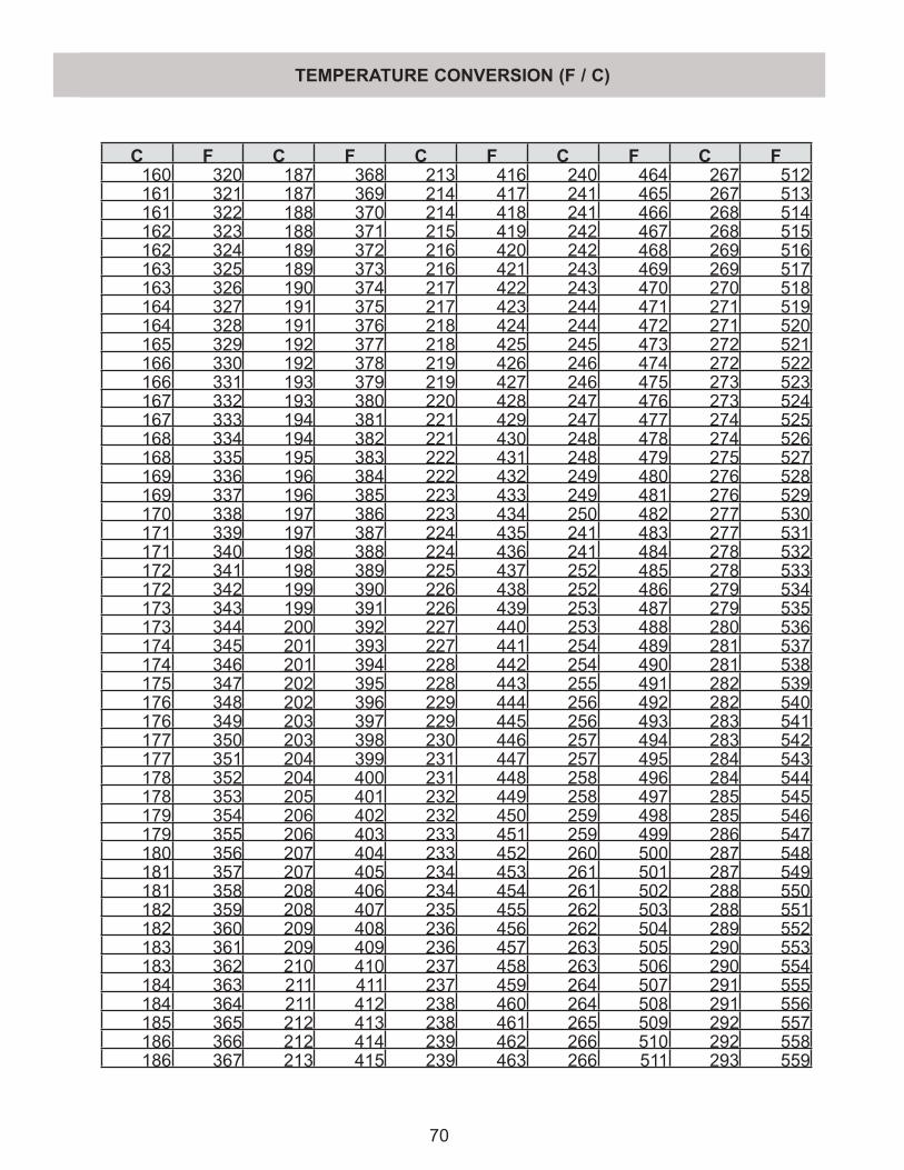
70
TEMPERATURE CONVERSION (F / C)
C F C F C F C F C F160 320 187 368 213 416 240 464 267 512161 321 187 369 214 417 241 465 267 513161 322 188 370 214 418 241 466 268 514162 323 188 371 215 419 242 467 268 515162 324 189 372 216 420 242 468 269 516163 325 189 373 216 421 243 469 269 517163 326 190 374 217 422 243 470 270 518164 327 191 375 217 423 244 471 271 519164 328 191 376 218 424 244 472 271 520165 329 192 377 218 425 245 473 272 521166 330 192 378 219 426 246 474 272 522166 331 193 379 219 427 246 475 273 523167 332 193 380 220 428 247 476 273 524167 333 194 381 221 429 247 477 274 525168 334 194 382 221 430 248 478 274 526168 335 195 383 222 431 248 479 275 527169 336 196 384 222 432 249 480 276 528169 337 196 385 223 433 249 481 276 529170 338 197 386 223 434 250 482 277 530171 339 197 387 224 435 241 483 277 531171 340 198 388 224 436 241 484 278 532172 341 198 389 225 437 252 485 278 533172 342 199 390 226 438 252 486 279 534173 343 199 391 226 439 253 487 279 535173 344 200 392 227 440 253 488 280 536174 345 201 393 227 441 254 489 281 537174 346 201 394 228 442 254 490 281 538175 347 202 395 228 443 255 491 282 539176 348 202 396 229 444 256 492 282 540176 349 203 397 229 445 256 493 283 541177 350 203 398 230 446 257 494 283 542177 351 204 399 231 447 257 495 284 543178 352 204 400 231 448 258 496 284 544178 353 205 401 232 449 258 497 285 545179 354 206 402 232 450 259 498 285 546179 355 206 403 233 451 259 499 286 547180 356 207 404 233 452 260 500 287 548181 357 207 405 234 453 261 501 287 549181 358 208 406 234 454 261 502 288 550182 359 208 407 235 455 262 503 288 551182 360 209 408 236 456 262 504 289 552183 361 209 409 236 457 263 505 290 553183 362 210 410 237 458 263 506 290 554184 363 211 411 237 459 264 507 291 555184 364 211 412 238 460 264 508 291 556185 365 212 413 238 461 265 509 292 557186 366 212 414 239 462 266 510 292 558186 367 213 415 239 463 266 511 293 559

71
MANUAL CORRECTIONS AND MODIFICATIONS
While every effort has been made to ensure that the information contained in this manual provided to you is updated, and contains accurate information, if you believe that an error has been made, or simply would like to suggest modifications, or improvements, please fill in the information below and fax it to 570-636-9874 or mail it to the address below. A review of any receieved forms will be considered on a regular basis.
Name __________________________________________________________________________
Address ________________________________________________________________________
City __________________________________ State _______________________Zip _________
Page Number in which error exists _______
Description of Error _________________________________________________________________________________________________________________________________________________________________________________________________________________________________________________________________________________________________________________________________________________________________________________________________________________________________________________
Suggestions or improvements to this manual: ____________________________________________________________________________________________________________________________________________________________________________________________________________________________________________________________________________________________________________________________________________________________________________________________________________________________________________________________________________________________________________
Fax to 570-636-9874- or -
Mail to:Garland Commercial Industies
McDonalds Sale / Service Account185 East South StreetFreeland, PA 18224
Thank you for your continued support!Garland P/N Rev 7d P/N 1881010 IN(021605)

®
Rev 7e P/N 1881010 IN(072105)
Related Documents