MV distribution LF circuit breakers up to 17.5 kV Catalogue 2007

Welcome message from author
This document is posted to help you gain knowledge. Please leave a comment to let me know what you think about it! Share it to your friends and learn new things together.
Transcript

MV distribution
LF circuit breakersup to 17.5 kV
Catalogue
2007

LF circuit breakers
One range of comprehensive and proven three-pole circuit breaker units for indoor installation using SF6 technology. Both compact and dependable, it is ideally suited to the most demanding applications and integrate perfectly in the Merlin Gerin Guiding System.This circuit breaker range meets IEC standard 62271-100.
LF circuit breakers fi xed version from 7.2 kV to 17.5 kV
LF circuit breakers withdrawable version from 7.2 kV to 17.5 kV
PE
5576
1P
E55
761p

1
General presentation 6
Panorama 9
LF circuit breakers fi xed version 11
LF circuit breakers withdrawable version 23
LFP circuit breakers 39
General contents
2
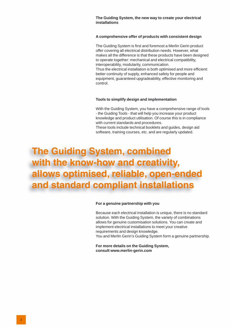
The Guiding System, the new way to create your electrical installations
A comprehensive offer of products with consistent design
The Guiding System is fi rst and foremost a Merlin Gerin product offer covering all electrical distribution needs. However, what makes all the difference is that these products have been designed to operate together: mechanical and electrical compatibility, interoperability, modularity, communication.Thus the electrical installation is both optimised and more effi cient: better continuity of supply, enhanced safety for people and equipment, guaranteed upgradeability, effective monitoring and control.
Tools to simplify design and implementation
With the Guiding System, you have a comprehensive range of tools - the Guiding Tools - that will help you increase your product knowledge and product utilisation. Of course this is in compliance with current standards and procedures.These tools include technical booklets and guides, design aid software, training courses, etc. and are regularly updated.
For a genuine partnership with you
Because each electrical installation is unique, there is no standard solution. With the Guiding System, the variety of combinations allows for genuine customisation solutions. You can create and implement electrical installations to meet your creative requirements and design knowledge. You and Merlin Gerin’s Guiding System form a genuine partnership.
For more details on the Guiding System,consult www.merlin-gerin.com
3
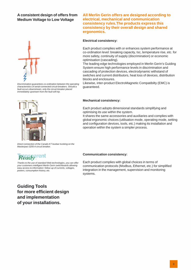
A consistent design of offers from Medium Voltage to Low Voltage
Discrimination guarantees co-ordination between the operating characteristics of serial-connected circuit-breakers. Should a fault occurs downstream, only the circuit-breaker placed immediately upstream from the fault will trip.
Direct connection of the Canalis KT busbar trunking on the Masterpact 3200 A circuit breaker.
Thanks to the use of standard Web technologies, you can offer your customers intelligent Merlin Gerin switchboards allowing easy access to information: follow-up of currents, voltages, powers, consumption history, etc.
Guiding Tools for more effi cient design and implementation of your installations.
All Merlin Gerin offers are designed according to electrical, mechanical and communication consistency rules.The products express this consistency by their overall design and shared ergonomics.
Electrical consistency:
Each product complies with or enhances system performance at co-ordination level: breaking capacity, Isc, temperature rise, etc. for more safety, continuity of supply (discrimination) or economic optimisation (cascading).The leading edge technologies employed in Merlin Gerin’s Guiding System ensure high performance levels in discrimination and cascading of protection devices, electrodynamic withstand of switches and current distributors, heat loss of devices, distribution blocks and enclosures.Likewise, inter-product ElectroMagnetic Compatibilty (EMC) is guaranteed.
Mechanical consistency:
Each product adopts dimensional standards simplifying and optimising its use within the system.It shares the same accessories and auxiliaries and complies with global ergonomic choices (utilisation mode, operating mode, setting and confi guration devices, tools, etc.) making its installation and operation within the system a simpler process.
Communication consistency:
Each product complies with global choices in terms of communication protocols (Modbus, Ethernet, etc.) for simplifi ed integration in the management, supervision and monitoring systems.
4
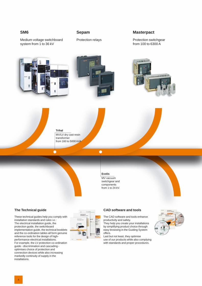
SM6
Medium voltage switchboard system from 1 to 36 kV
Sepam
Protection relays
Masterpact
Protection switchgear from 100 to 6300 A
The Technical guide
These technical guides help you comply with installation standards and rules i.e.:The electrical installation guide, the protection guide, the switchboard implementation guide, the technical booklets and the co-ordination tables all form genuine reference tools for the design of high-performance electrical installations.For example, the LV protection co-ordination guide - discrimination and cascading - optimises choice of protection and connection devices while also increasing markedly continuity of supply in the installations.
CAD software and tools
The CAD software and tools enhance productivity and safety.They help you create your installations by simplifying product choice through easy browsing in the Guiding System offers.Last but not least, they optimise use of our products while also complying with standards and proper procedures.
TrihalMV/LV dry cast resin transformer from 160 to 5000 kVA
EvolisMV vacuum switchgear and components from 1 to 24 kV.

5
Compact
Protection switchgear system from 100 to 630 A
Multi 9
Modular protection switchgear system up to 125 A
Prisma Plus
Functional system for electrical distribution switchboards up to 3200 A
Training
Training allows you to acquire the Merlin Gerin expertise (installation design, work with power on, etc.) for increased effi ciency and a guarantee of improved customer service.The training catalogue includes beginner’s courses in electrical distribution, knowledge of MV and LV switchgear, operation and maintenance of installations, design of LV installations to give but a few examples.
merlin-gerin.com
This international site allows you to access all the Merlin Gerin products in just 2 clicks via comprehensive range data-sheets, with direct links to:
complete library: technical documents, catalogs, FAQs, brochures…
selection guides from the e-catalogproduct discovery sites and their Flash
animations.You will also fi nd illustrated overviews, news to which you can subscribe, the list of country contacts…
b
bb
PragmaEnclosures for distribution switchboards up to 160 A
PowerLogicPowermanagement
CanalisPrefabricated Busbar Trunking from 25 to 4000 A
6
With over 37 years’ industrial experience in SF6 techniques and over 300,000 installed devices throughout the world, Merlin Gerin is today one of the foremost manufacturers of SF6 switchgear. Merlin Gerin has developed a wide range of high performance and reliable devices operating faultlessly on all 5 continents. Continuously increasing its performance, the company maintains a very high level of innovation in its offer.
SafetyThe breaking medium is sulfur hexafl uoride (SF6) used at low pressure. The insulating enclosure containing the circuit breaker pole(s) is equipped with a safety membrane. In addition, the rated characteristics, breaking the rated current under the rated voltage, are generally maintained at zero relative bars of SF6.
ReliabilityThe motor-charged spring stored energy operating mechanism is a key factor of device reliability: Merlin Gerin cumulates 37 years’ experience with this type of mechanism, 300,000 of which are already in operation.Merlin Gerin’s mastery of design and the testing of sealed systems guarantees sustained device performance for at least 30 years.
Increased enduranceThe mechanical and electrical endurance of Merlin Gerin SF6 breaking devices are in conformity with the most demanding specifi cations recommended by the IEC.These devices therefore meet requirements for even the most exposed of networks.
Less maintenanceThroughout the device’s service life, which in normal operating conditions may be at least 30 years, the only maintenance required is on the mechanical operating mechanism, once every 10 years or every 10,000 operations. Although no maintenance is performed on poles, a diagnosis is possible:
contact wear can be checked by external pole measurementSF6 pressure can be continually monitored by a pressure switch.
Environmentally-friendlyMerlin Gerin devices have been designed to ensure protection of the environment:
the materials used, both insulating and conductive, are identifi ed and easy to separate and recycle,
the SF6 gas is under control from production through to the circuit breaker’s end of life. In particular it can be recovered at the end of the circuit breaker’s life and re-used after treatment in line with the new European directive,
an end of life manual for the product details procedures for dismantling and recycling components.
Quality AssuranceDuring production, each circuit breaker undergoes systematic routine tests in order to check quality and conformity:
pole sealing checkchecking the correct mechanical operation of the device,
plus its associated locking mechanismschecking simultaneous closing of contactschecking power frequency insulation levelchecking main circuit resistancechecking auxiliary circuit insulationchecking auxiliary circuit electrical resistancechecking switching speedschecking the switching cyclemeasuring the switching times.
The results are recorded on the test certifi cate for each device which is initialed by the quality control department.
Certifi cationThe quality system for the design and production of LF range circuit breakers is certifi ed in conformity with ISO 9001: 2000 quality assurance standard requirements.The environmental management system adopted by Merlin Gerin production sites for the production of LF range circuit breakers has been assessed and judged to be in conformity with requirements in standard ISO 14001.
bb
b
b
b
bb
bbbbbbbb
6105
1ND
E55
745
DE
5574
6
General presentation LF circuit breakersThe advantages of proven technology
7
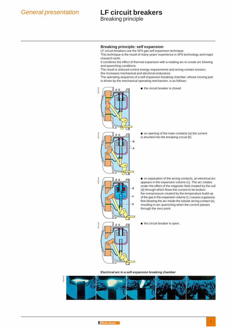
Breaking principle: self expansionLF circuit breakers use the SF6 gas self expansion technique. This technique is the result of many years’ experience in SF6 technology and major research work.It combines the effect of thermal expansion with a rotating arc to create arc blowing and quenching conditions.The result is reduced control energy requirements and arcing contact erosion; this increases mechanical and electrical endurance.The operating sequence of a self-expansion breaking chamber, whose moving part is driven by the mechanical operating mechanism, is as follows:
DE
5124
2 the circuit breaker is closedb
DE
5124
3 on opening of the main contacts (a) the current is shunted into the breaking circuit (b)b
DE
5124
4 on separation of the arcing contacts, an electrical arc appears in the expansion volume (c). The arc rotates under the effect of the magnetic fi eld created by the coil (d) through which fl ows the current to be broken: the overpressure created by the temperature build-up of the gas in the expansion volume (c ) causes a gaseous fl ow blowing the arc inside the tubular arcing contact (e), resulting in arc quenching when the current passes through the zero point
b
DE
5124
5 the circuit breaker is open.b
Electrical arc in a self-expansion breaking chamber
PE
5576
4
General presentation LF circuit breakersBreaking principle

8
9
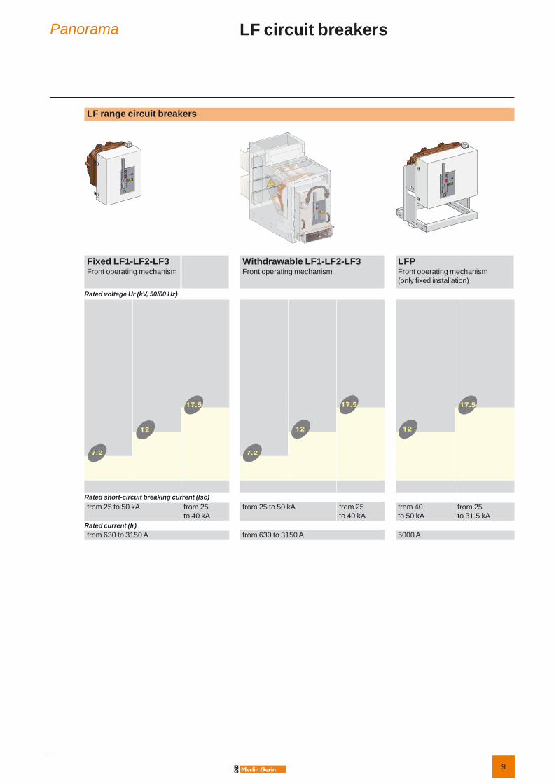
LF range circuit breakers
Fixed LF1-LF2-LF3Front operating mechanism
Withdrawable LF1-LF2-LF3Front operating mechanism
LFPFront operating mechanism(only fi xed installation)
Rated voltage Ur (kV, 50/60 Hz)
Rated short-circuit breaking current (Isc)from 25 to 50 kA from 25
to 40 kAfrom 25 to 50 kA from 25
to 40 kAfrom 40 to 50 kA
from 25 to 31.5 kA
Rated current (Ir)from 630 to 3150 A from 630 to 3150 A 5000 A
Panorama LF circuit breakers
10
These technical guides help you comply with installation standardsand rules i.e.:the electrical installation guide, the protection guide, the switchboard implementation guide,the technical booklets and the co-ordination tables all form genuine reference tools for the design of high performance electrical installations.For example, the LV protection co-ordination guide - discrimination and cascading - optimises choice of protection and connection devices while also increasing markedly continuity of supply in the installations.
This international site allows you to access all the Merlin Gerin products in just 2 clicks via comprehensive range data-sheets, with direct links to:
complete library: technical documents, catalogs, FAQs, brochures…
selection guides from the e-catalog.
product discovery sites and their Flash animations.
You will also fi nd illustrated overviews, news to which you can subscribe, the list of country contacts…
b
b
b

11
LF circuit breakers fi xed version
LF circuit breakers
General presentation 6Panorama 9
Presentation 13General characteristics 14Description of functions 16RI stored energy operating mechanism 16Wiring diagram 16Opening circuit 17Remote control 18Indication and locking/interlocking 19
Dimensions 20Order form 21
LF circuit breakers withdrawable version 23LFP circuit breakers 39

12
13
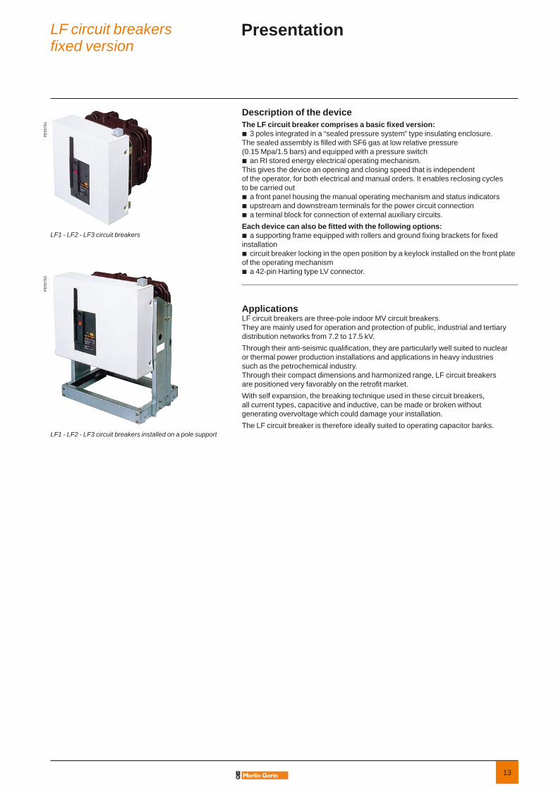
Description of the deviceThe LF circuit breaker comprises a basic fi xed version:
3 poles integrated in a “sealed pressure system” type insulating enclosure. The sealed assembly is fi lled with SF6 gas at low relative pressure (0.15 Mpa/1.5 bars) and equipped with a pressure switch
an RI stored energy electrical operating mechanism.This gives the device an opening and closing speed that is independent of the operator, for both electrical and manual orders. It enables reclosing cycles to be carried out
a front panel housing the manual operating mechanism and status indicatorsupstream and downstream terminals for the power circuit connectiona terminal block for connection of external auxiliary circuits.
Each device can also be fi tted with the following options:a supporting frame equipped with rollers and ground fi xing brackets for fi xed
installationcircuit breaker locking in the open position by a keylock installed on the front plate
of the operating mechanisma 42-pin Harting type LV connector.
Applications LF circuit breakers are three-pole indoor MV circuit breakers. They are mainly used for operation and protection of public, industrial and tertiary distribution networks from 7.2 to 17.5 kV. Through their anti-seismic qualifi cation, they are particularly well suited to nuclear or thermal power production installations and applications in heavy industries such as the petrochemical industry.Through their compact dimensions and harmonized range, LF circuit breakers are positioned very favorably on the retrofi t market.With self expansion, the breaking technique used in these circuit breakers, all current types, capacitive and inductive, can be made or broken without generating overvoltage which could damage your installation.The LF circuit breaker is therefore ideally suited to operating capacitor banks.
b
b
bbb
b
b
b
PE
5576
1
LF1 - LF2 - LF3 circuit breakers
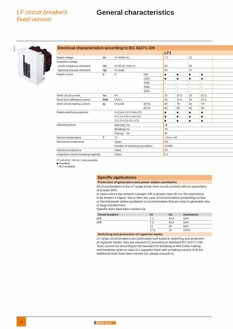
LF1 - LF2 - LF3 circuit breakers installed on a pole support
PE
5576
3
LF circuit breakersfi xed version
Presentation
14
Electrical characteristics according to IEC 62271-100LF1
Rated voltage Ur kV 50/60 Hz 7.2 12Insulation voltage- power frequency withstand Ud kV 50 Hz 1min (*) 20 28- lightning impulse withstand Up kV peak 60 75Rated current Ir A 630 b b b b
1250 b b b b
2000 – – – –2500 – – – –3150 – – – –
Short circuit current Isc kA 25 31.5 25 31.5Short time withstand current Ik/tk kA/3 s 25 31.5 25 31.5Short-circuit making current Ip kA peak 50 Hz 63 79 63 79
60 Hz 65 82 65 82Rated switching sequence O-3 min-CO-3 min-CO b b b b
O-0.3 s-CO-3 min-CO b b b b
O-0.3 s-CO-15 s-CO b b b b
Operating times Opening ms 48Breaking ms 70Closing ms 65
Service temperature T °C –25 to +40Mechanical endurance Class M2
Number of switching operations 10 000Electrical endurance Class E2Capacitive current breaking capacity Class C2
(*) Ud 42 kV 50 Hz, 1 min possibleb Available– Non available.
PE
5576
1
Specifi c applicationsProtection of generators and power station auxiliaries
All circuit breakers in the LF range break short circuit currents with an asymmetry of at least 30%. In cases where the network constant X/R is greater than 45 ms, the asymmetry to be broken is higher; this is often the case of circuit breakers protecting nuclear or thermal power station auxiliaries or circuit breakers that are close to generator sets or large transformers. Specifi c tests have been carried out:
Circuit breakers kV kA AsymmetryLF2 7.2 43.5 50%LF3 7.2 43.5 50%
12 40 50%17.5 25 100%
Switching and protection of capacitor banks LF range circuit breakers are particularly well suited to switching and protection of capacitor banks; they are classed C2 according to standard IEC 62271-100. Tests carried out according to the standard for breaking at 400 A with making and breaking cycles in case of a capacitor bank with a making current of 20 kA.Additional tests have been carried out: please consult us.
LF circuit breakersfi xed version
General characteristics

15
LF2 LF37.2 12 17.5 7.2 12 17.5
20 28 38 20 28 3860 75 95 60 75 95b b b b b – – – – – – – – – – –b b b b b – – – – – – – b – – b
b b b b b – – – – – – – – – – –– – – – – b b b b b b b b b b b
– – – – – – b b b – b b b b b b
40 50 40 25 31.5 25 31.5 40 50 25 31.5 40 50 25 31.5 4040 50 40 25 31.5 25 31.5 40 50 25 31.5 40 50 25 31.5 40100 125 100 63 79 63 79 100 125 63 79 100 125 63 79 100104 130 104 65 82 65 82 104 130 65 82 104 130 65 82 104b b b b b b b b b b b b b b b b
b b b b b b b b b b b b b b b –b b b b b b b b b b b b b b b –48 4870 7065 65–25 to +40 –25 to +40M2 M210 000 10 000E2 E2C2 C2
LF circuit breakersfi xed version
General characteristics (cont.)
16
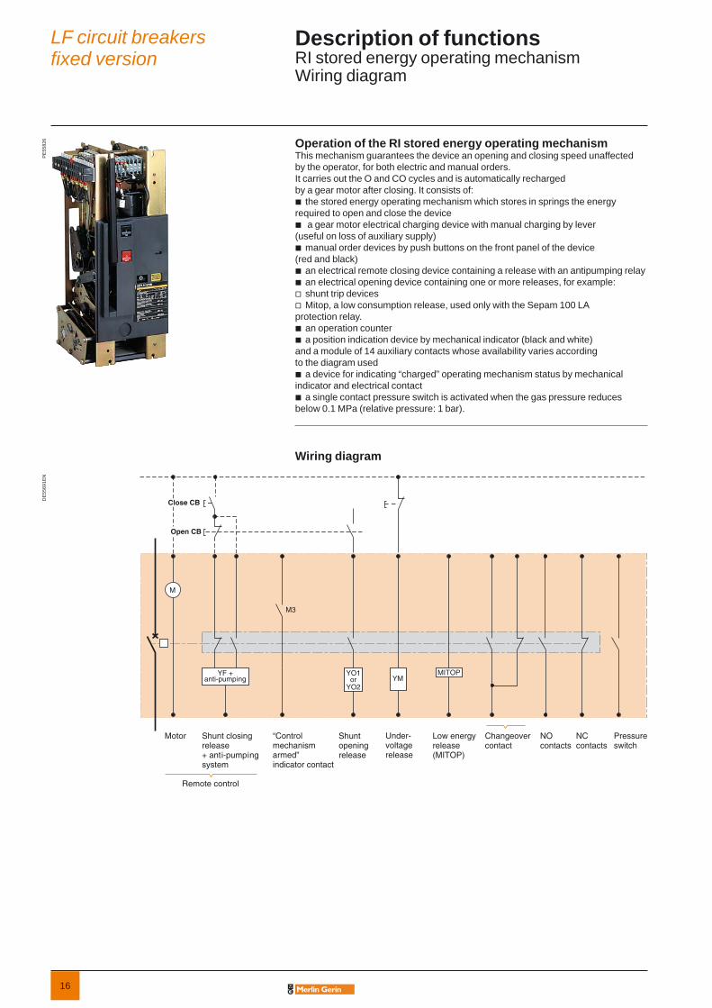
Operation of the RI stored energy operating mechanismThis mechanism guarantees the device an opening and closing speed unaffected by the operator, for both electric and manual orders. It carries out the O and CO cycles and is automatically recharged by a gear motor after closing. It consists of:
the stored energy operating mechanism which stores in springs the energy required to open and close the device
a gear motor electrical charging device with manual charging by lever(useful on loss of auxiliary supply)
manual order devices by push buttons on the front panel of the device (red and black)
an electrical remote closing device containing a release with an antipumping relayan electrical opening device containing one or more releases, for example:shunt trip devicesMitop, a low consumption release, used only with the Sepam 100 LA
protection relay.an operation counter a position indication device by mechanical indicator (black and white)
and a module of 14 auxiliary contacts whose availability varies according to the diagram used
a device for indicating “charged” operating mechanism status by mechanical indicator and electrical contact
a single contact pressure switch is activated when the gas pressure reduces below 0.1 MPa (relative pressure: 1 bar).
Wiring diagram
b
b
b
bbvv
bb
b
b
PE
5582
6D
E55
691E
NLF circuit breakersfi xed version
Description of functionsRI stored energy operating mechanismWiring diagram
Pressureswitch
M
YF +anti-pumping
Motor Shunt closingrelease+ anti-pumpingsystem
Remote control
Shunt openingrelease
Under-voltagerelease
Low energyrelease(MITOP)
NO contacts
Changeovercontact
NC contacts
Close CB
Open CB
YO1or
YO2YM
M3
MITOP
“Control mechanism armed” indicator contact

17
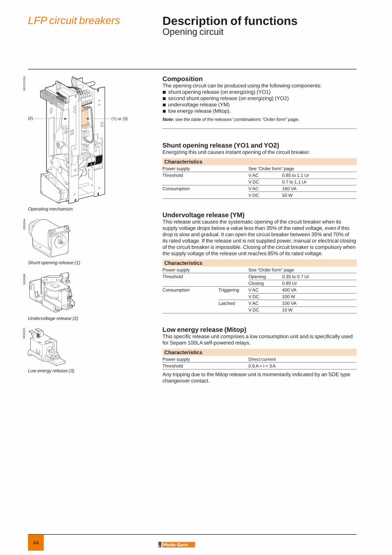
CompositionThe opening circuit can be produced using the following components:
shunt opening release (on energizing) (YO1)second shunt opening release (on energizing) (YO2)undervoltage release (YM)low energy release (Mitop).
Note: see the table of the releases’ combinations “Order form” page.
Shunt opening release (YO1 and YO2)Energizing this unit causes instant opening of the circuit breaker.
CharacteristicsPower supply See “Order form” pageThreshold V AC 0.85 to 1.1 Ur
V DC 0.7 to 1.1 UrConsumption V AC 160 VA
V DC 50 W
Undervoltage release (YM)This release unit causes the systematic opening of the circuit breaker when its supply voltage drops below a value less than 35% of the rated voltage, even if this drop is slow and gradual. It can open the circuit breaker between 35% and 70% of its rated voltage. If the release unit is not supplied power, manual or electrical closing of the circuit breaker is impossible. Closing of the circuit breaker is compulsory when the supply voltage of the release unit reaches 85% of its rated voltage.
CharacteristicsPower supply See “Order form” pageThreshold Opening 0.35 to 0.7 Ur
Closing 0.85 UrConsumption Triggering V AC 400 VA
V DC 100 WLatched V AC 100 VA
V DC 10 W
Low energy release (Mitop)This specifi c release unit comprises a low consumption unit and is specifi cally used for Sepam 100LA self-powered relays.
CharacteristicsPower supply Direct current Threshold 0.6 A < I < 3 A
Any tripping due to the Mitop release unit is momentarily indicated by an SDE type changeover contact.
bbbb
DE
5570
1EN
DE
6009
4D
E60
089
DE
6009
1
Operating device
Shunt opening release (1)
Undervoltage release (2)
Low energy release (3)
LF circuit breakersfi xed version
Description of functionsOpening circuit
(1) or (3)(2)

18
DE
5570
2D
E60
093
DE
6015
1D
E60
087
(4)
(5)(6)
Operating mechanism
Electrical motor and gearing (4)
Shunt closing release (5)
Operation counter (6)
FunctionRemote control enables the remote opening and closing of the circuit breaker.
CompositionThe remote control mechanism comprises:
an electrical motor with gearing a shunt closing release (YF) combined with an anti-pumping devicean operation counter.
Electrical motor with gearing (M)The electrical motor arms and re-arms the stored energy unit as soon as the circuit breaker is closed. This allows the instant closing of the device after opening. The arming lever is only used as a back-up operating mechanism in the case of any auxiliary power supply. The M3 contact indicates the end of arming operations.
CharacteristicsPower supply See “Order form” pageThreshold V AC/V DC 0.85 to 1.1 UrConsumption V AC 380 VA
V DC 380 W
Shunt closing release (YF)This allows the remote closing of the circuit breaker when the operating mechanism is armed.
CharacteristicsPower supply See “Order form” pageThreshold V AC 0.85 to 1.1 Ur
V DC 0.85 to 1.1 UrConsumption V AC 160 VA
V DC 50 W
The anti-pumping relay enables the guaranteeing of opening priority in the case of a permanent closing order. This therefore avoids the device being caught in a uncontrolled opening-closing loop.
Operation counterThe operation counter is visible on the front panel.It displays the number of switching cycles (CO) that the device has carried out.
bbb
LF circuit breakersfi xed version
Description of functionsRemote control
19
DE
5569
0D
E60
124
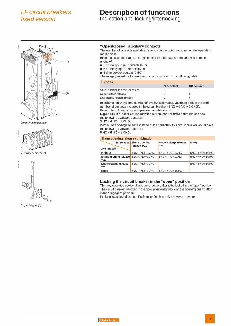
Operating mechanism
Keylocking kit (8)
“Open/closed” auxiliary contacts The number of contacts available depends on the options chosen on the operating mechanism.In the basic confi guration, the circuit breaker’s operating mechanism comprises a total of:
5 normally closed contacts (NC)5 normally open contacts (NO)1 changeover contact (CHG).
The usage procedure for auxiliary contacts is given in the following table:
OptionsNC contact NO contact
Shunt opening release (each one) 0 1Undervoltage release 0 0Low energy release (Mitop) 0 0
In order to know the fi nal number of available contacts, you must deduct the total number of contacts included in the circuit breaker (5 NC + 5 NO + 1 CHG), the number of contacts used given in the table above.E.g.: a circuit breaker equipped with a remote control and a shunt trip unit has the following available contacts: 5 NC + 4 NO + 1 CHG. With a undervoltage release instead of the shunt trip, this circuit breaker would have the following available contacts: 5 NC + 5 NO + 1 CHG.
Shunt opening release combination1st release
2nd release
Shunt opening release YO1
Undervoltage release YM
Mitop
Without 5NC + 4NO + 1CHG 5NC + 5NO+ 1CHG 5NC + 5NO + 1CHGShunt opening release YO2
5NC + 3NO + 1CHG 5NC + 4NO+ 1CHG 5NC + 4NO + 1CHG
Undervoltage release YM
5NC + 4NO + 1CHG 5NC + 5NO + 1CHG
Mitop 5NC + 4NO + 1CHG 5NC + 5NO + 1CHG
Locking the circuit breaker in the “open” positionThis key-operated device allows the circuit breaker to be locked in the “open” position. The circuit breaker is locked in the open position by blocking the opening push button in the “engaged” position.Locking is achieved using a Profalux or Ronis captive key type keylock.
bbb
DE
5195
3
Auxiliary contacts (7)
(8)
(7)
LF circuit breakersfi xed version
Description of functionsIndication and locking/interlocking

20
DeviceBasic fi xed
DE
5570
4EN
330590
50 50
A
35
offon
offon
536
5025
270connection
34
LF1 LF2 LF3A 493 554 728Weight (kg) 106 128 149.5
Fixed with a support frame
DE
5570
5
995
B
offon
offon
539 34
555
330
LF1 LF2 LF3B 542 602 776Weight (kg) 124 148 168
ConnectionsDirect to the device Connection on pads
LF1LF2 < 2000 A < 95 kV impulseLF3 < 2500 A and < 95 kV impulse
bbb
LF2:2000 A1250 A/95 kV impulse630 A/95 kV impulseLF3: 1250 A/95 kV impulse
bvvvb
LF3: 2500 A/95 kV impulse3150 A/95 kV impulse
bvv
DE
5570
6EN
D
C
3 x 30
7,5
E
E
63
3 x 2M10 x 26 (effective length)
3 x 40 DE
5570
7
20
20 40
15
60
22,5
15
4 x ø12
DE
5570
8
52
11 11
40
128
8 Ø 12,2
32
66 40
LF1 LF2 LF3 Note:b recommended connection screw M10 class 8.8. Tightening torque: 50 Nm with contact washer.b connectors delivered mounted on the deviceb for more details refer to the dimensional drawings
C 160 180 240D 145 165 225E 145 165 225
LF circuit breakersfi xed version
DimensionsLF1, LF2, LF3 circuit breakers

21
Basic fi xed circuit breaker Quantity
Rated voltage Ur (kV)
Impulse voltage Up (kVbil)
short-circuit current Isc (kA)
Rated current Ir (A)
Frequency 50 Hz 60 Hz
Colour for push buttons and indicators IEC standard ANSI standard
Push buttons open/close: Red/black
Indicator open/close: Black/white Green/red
Operating mechanism charged/discharged: White/yellow Charge/discharge
Circuit breaker options1st opening release (see possible choices in combination table below)
Shunt opening release YO124 Vdc 60 Vdc 220 Vdc 220 Vac (50 Hz) 30 Vdc 110 Vdc 48 Vac (50 Hz) 120 Vac (60 Hz) 48 Vdc 125 Vdc 110 Vac (50 Hz) 240 Vac (60 Hz)
2nd opening release (see possible choices in combination table below)Shunt opening release YO2
24 Vdc 60 Vdc 220 Vdc 220 Vac (50 Hz) 30 Vdc 110 Vdc 48 Vac (50 Hz) 120 Vac (60 Hz) 48 Vdc 125 Vdc 110 Vac (50 Hz) 240 Vac (60 Hz)
Undervoltage release YM24 Vdc 60 Vdc 220 Vdc 220 Vac (50 Hz) 30 Vdc 110 Vdc 48 Vac (50 Hz) 120 Vac (60 Hz) 48 Vdc 125 Vdc 110 Vac (50 Hz) 240 Vac (60 Hz)
Mitop (not available with sismic version)Without contact With contact
Remote controlElectrical motor M 24…32 Vdc 110…127 Vdc/ac
48…60 Vdc/ac 220…250 Vdc/ac Shunt closing release YF
24 Vdc 60 Vdc 220 Vdc 220 Vac (50 Hz) 30 Vdc 110 Vdc 48 Vac (50 Hz) 120 Vac (60 Hz) 48 Vdc 125 Vdc 110 Vac (50 Hz) 240 Vac (60 Hz)
Low voltage wiring connection Male plug (1.2 m) Female socket (2 m) Locking C.B. in open position Ronis Profalux Sismic version (consult us) Support frame Leafl ets language French English
Different releases combinationsShunt opening releases YO1/YO2 1 2 1 1Undervoltage release YM 1 1 1Mitop 1 1 1
Only one of the boxes (ticked X or fi lled by the needed value) have to be considered between each horizontal line. Orange box X corresponds to none priced functions.
LF circuit breakersfi xed version
Order formLF1, LF2, LF3 fi xed up to 17.5 kV
22
The CAD softwareand tools enhance productivity and safety. They help you createyour installations by simplifying product choice through easy browsingin the Guiding System offers.Last but not least, they optimise use of our products while also complying with standards and proper procedures.
This international site allows you to access all the Merlin Gerin products in just 2 clicks via comprehensive range data-sheets, with direct links to:
complete library: technical documents, catalogs, FAQs, brochures…
selection guides from the e-catalog.
product discovery sites and their Flash animations.
You will also fi nd illustrated overviews, news to which you can subscribe, the list of country contacts…
b
b
b

23
LF circuit breakers withdrawable version
LF circuit breakers
General presentation 6Panorama 9LF circuit breakers fixed version 11
Presentation 25General characteristics 26Description of functions 28Racking in 28Connection 30RI stored energy operating mechanism 31Wiring diagram 31Opening circuit 32Remote control 33Indication and locking/interlocking 34Safety functions 35
Dimensions 36Order form 37
LFP circuit breakers 39

24
25
PE
4046
1p
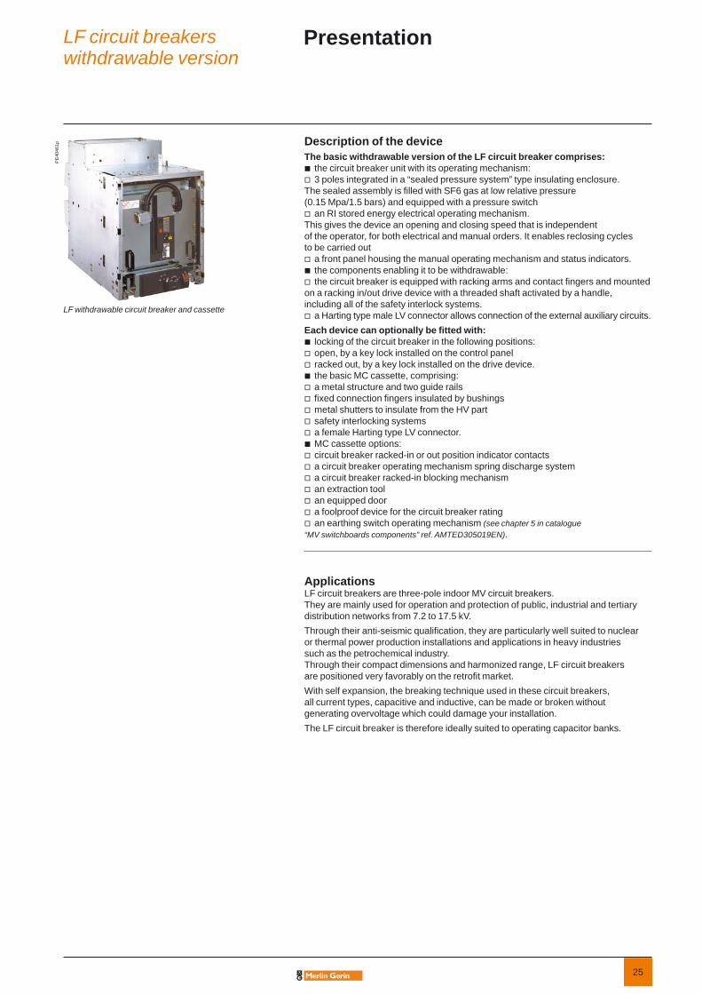
LF withdrawable circuit breaker and cassette
Description of the deviceThe basic withdrawable version of the LF circuit breaker comprises:
the circuit breaker unit with its operating mechanism:3 poles integrated in a “sealed pressure system” type insulating enclosure.
The sealed assembly is fi lled with SF6 gas at low relative pressure (0.15 Mpa/1.5 bars) and equipped with a pressure switch
an RI stored energy electrical operating mechanism.This gives the device an opening and closing speed that is independent of the operator, for both electrical and manual orders. It enables reclosing cycles to be carried out
a front panel housing the manual operating mechanism and status indicators.the components enabling it to be withdrawable:the circuit breaker is equipped with racking arms and contact fi ngers and mounted
on a racking in/out drive device with a threaded shaft activated by a handle, including all of the safety interlock systems.
a Harting type male LV connector allows connection of the external auxiliary circuits.Each device can optionally be fi tted with:
locking of the circuit breaker in the following positions:open, by a key lock installed on the control panelracked out, by a key lock installed on the drive device.the basic MC cassette, comprising:a metal structure and two guide railsfi xed connection fi ngers insulated by bushingsmetal shutters to insulate from the HV partsafety interlocking systemsa female Harting type LV connector.MC cassette options:circuit breaker racked-in or out position indicator contactsa circuit breaker operating mechanism spring discharge systema circuit breaker racked-in blocking mechanisman extraction toolan equipped doora foolproof device for the circuit breaker ratingan earthing switch operating mechanism (see chapter 5 in catalogue
“MV switchboards components” ref. AMTED305019EN).
Applications LF circuit breakers are three-pole indoor MV circuit breakers. They are mainly used for operation and protection of public, industrial and tertiary distribution networks from 7.2 to 17.5 kV. Through their anti-seismic qualifi cation, they are particularly well suited to nuclear or thermal power production installations and applications in heavy industries such as the petrochemical industry.Through their compact dimensions and harmonized range, LF circuit breakers are positioned very favorably on the retrofi t market.With self expansion, the breaking technique used in these circuit breakers, all current types, capacitive and inductive, can be made or broken without generating overvoltage which could damage your installation.The LF circuit breaker is therefore ideally suited to operating capacitor banks.
bv
v
vbv
v
bvvbvvvvvbvvvvvvv
LF circuit breakerswithdrawable version
Presentation

26
Electrical characteristics according to IEC 62271-100Circuit breaker/Cassette LF1/MC1Rated voltage Ur kV 50/60 Hz 7.2 12Insulation voltage- power frequency withstand Ud kV 50 Hz 1min (*) 20 28- lightning impulse withstand Up kV peak 60 75Rated current Ir A 630 b b b b
1250 b b b b
2000 – – – –2500 – – – –3150 – – – –
Short circuit current Isc kA 25 31.5 25 31.5Short time withstand current Ik/tk kA/3 s, kA/1 s 25 31.5 25 31.5Short-circuit making current Ip kA peak 50 Hz 63 79 63 79
60 Hz 65 82 65 82Rated switching sequence O-3 min-CO-3 min-CO b b b b
O-0.3 s-CO-3 min-CO b b b b
O-0.3 s-CO-15 s-CO b b b b
Operating times Opening ms 48Breaking ms 70Closing ms 65
Service temperature T °C –25 to +40Mechanical endurance Class M2
Number of switching operations 10 000Electrical endurance Class E2Capacitive current breaking capacity Class C2
(*) Ud 42 kV 50 Hz, 1 min possible(**) Rated short-circuit breaking duration (tk): 1 sb Available– Non available.
PE
4046
1p
Specifi c applicationsProtection of generators and power station auxiliaries
All circuit breakers in the LF range break short circuit currents with an asymmetry of at least 30%. In cases where the network constant X/R is greater than 45 ms, the asymmetry to be broken is higher; this is often the case of circuit breakers protecting nuclear or thermal power station auxiliaries or circuit breakers that are close to generator sets or large transformers. Specifi c tests have been carried out:
Circuit breakers kV kA AsymmetryLF2 7.2 43.5 50%LF3 7.2 43.5 50%
12 40 50%17.5 25 100%
Switching and protection of capacitor banks LF range circuit breakers are particularly well suited to switching and protection of capacitor banks; they are classed C2 according to standard IEC 62271-100. Tests carried out according to the standard for breaking at 400 A with making and breaking cycles in case of a capacitor bank with a making current of 20 kA.Additional tests have been carried out: please consult us.
LF circuit breakerswithdrawable version
General characteristics

27
LF2/MC2 LF3/MC37.2 12 17.5 7.2 12 17.5
20 28 38 20 28 3860 75 95 60 75 95b b b b b – – – – – – – – – – –b b b b b – – – – – – – – – – –– – – – – – – – – – – – b – – b
– – – – – b b b b b b b b b b b
– – – – – – b b b – b b b b b b
40 50 40 25 31.5 25 31.5 40 50 25 31.5 40 50 25 31.5 4040 50 (**) 40 25 31.5 25 31.5 40 50 (**) 25 31.5 40 50 (**) 25 31.5 40100 125 100 63 79 63 79 100 125 63 79 100 125 63 79 100104 130 104 65 82 65 82 104 130 65 82 104 130 65 82 104b b b b b b b b b b b b b b b b
b b b b b b b b b b b b b b b –b b b b b b b b b b b b b b b –48 4870 7065 65–25 to +40 –25 to +40M2 M210 000 10 000E2 E2C2 C2
LF circuit breakerswithdrawable version
General characteristics (cont.)

28
DE
5249
5 Assembly componentsThe “racking-in/out” function is achieved by:
the withdrawable circuit breaker with its LV connector (mobile part)the cassette with its bushings (fi xed part).
Circuit breaker operationThe withdrawable circuit breaker can be placed in 3 stable positions:
service position: circuit breaker racked in and locked in position;LV plugs connected
test position: circuit breaker racked out and locked in position;LV plug connected
disconnected position: circuit breaker extracted and locked in this position, LV plug disconnected.
Circuit breaker safety functionsA drive system using a threaded shaft gives easier racking and unracking. Test position contactThis is activated when the circuit breaker is in the “test” or “service” position.Earthing is achieved throughout the operation via the racking carriage casters. An addition earthing system can be supplied as an option.Interlocking mechanismsIn conformity with IEC standards 62271-100 and 62271-200, the following interlocks are available:
impossibility of racking in or out is the circuit breaker is not in the “open” positionimpossible to rack in the circuit breaker when the LV plug is not connectedimpossible to disconnect the LV plug if the circuit breaker is not racked-out.
Cubicle door interlocking mechanismThe carriage is equipped with a device that enables interlocking between the racking out of the circuit breaker and the cubicle door:
possible to rack in the circuit breaker only if the door is closedpossible to open the door only if the circuit breaker is racked out.
This device must be disabled if the interlocking function is not present.
bb
b
b
b
bbb
bb
Operation position
DE
5249
6
Test position
DE
5249
7
Disconnected position
DE
5249
8D
E52
499
Interlocking door-cubicle
LF circuit breakerswithdrawable version
Description of functionsRacking in

29
MC cassette safety functionsThe MC cassette is designed to receive the LF circuit breaker and comprises the following components ensuring safety when racking-in (see details in the Installation Guide ref. 07897536EN).Metal structure with two guide railsThe rails guide the LF circuit breaker during racking-in/out operations.Fixed connection fi ngers insulated by bushingsThe three ends of the circuit breaker, fi tted with racking clusters, provide the contact with these three fi ngers.Metal shutters to insulate from the MV partThree shutters mounted on the structure stop access to the racking fi ngers when the circuit breaker is extracted (protection index: IP2X).Safety interlocking systemsWhen carrying out maintenance operations, it is possible to:
padlock the shutters in the closed positionunlock the access mechanism to the fi xed contacts.
Anti-drop functionThis function ensures operator safety during circuit breaker extraction.
Compulsory MC cassette accessoriesFemale Harting low voltage connectorA connector with a cable can either be delivered with the circuit breaker, with the circuit breaker plus the cassette, or separately.Panel with circuit breaker operation pictogramsA self-adhesive panel shows racking-in and out operations for the circuit breaker. This is systematically delivered when the circuit breaker is ordered either with the cassette or as a separate order.Racking handleThe handle is used for circuit breaker racking-in/out operations and for earthing switch opening and closing operations.Extraction tool
A standard tool allows the breaking device to be extracted from each cassette version, whatever the installation height, up to 800 mm from the ground.
A simplifi ed extraction tool can be manufactured locally according to the installation height.50 kA fi xing lockThis upper lock enabling the circuit breaker to be held in the cassette in the case of a fault, is compulsory for LF2/LF3 circuit breakers with a 50 kA withstand.
MC cassette optionsCircuit breaker racked-in or racked-out position indicator contacts6 contacts (3 NO + 3 NC) or 12 contacts (6 NO + 6 NC)Operating mechanism spring discharge systemCircuit breaker operating mechanism springs are automatically discharged when it is extracted from the cubicle. This function avoids any risk of unwanted circuit breaker closing.Mechanical circuit breaker racked-in lockThis option is included when the earthing switch is installed. However, it can be delivered separately if the earthing circuit breaker is not required: it takes the space and volume of the earthing switch operating mechanism.Equipped MV access doorPossibility of delivering a fully equipped, painted door (RAL 9001) available with or without the manual circuit breaker closing mechanism.Possibility of producing the door locally (drawings and accessories available).Foolproofi ng deviceThis enables foolproofi ng of the circuit breaker rating relative to the cassette rating. This system is mounted on the cassette side. The corresponding combining of the right circuit breaker rating must be carried out by the panel builder.Earthing switch operating mechanismThis can be mounted under the cassette, for suitable interlocking between the circuit breaker and the earthing switch (see detailed description in chapter 5 catalogue “MV switchboards components” ref. AMTED305019EN).
bb
b
b
DE
5250
0D
E52
501
Extraction tool
Indication contacts
DE
5250
5
(A) 50 kA interlock(B) Discharge of the circuit breaker operating mechanism on extraction
Cassette/circuit breaker foolproofi ng device
DE
5250
3D
E52
502
LF circuit breakerswithdrawable version
Description of functionsRacking in (cont.)
30
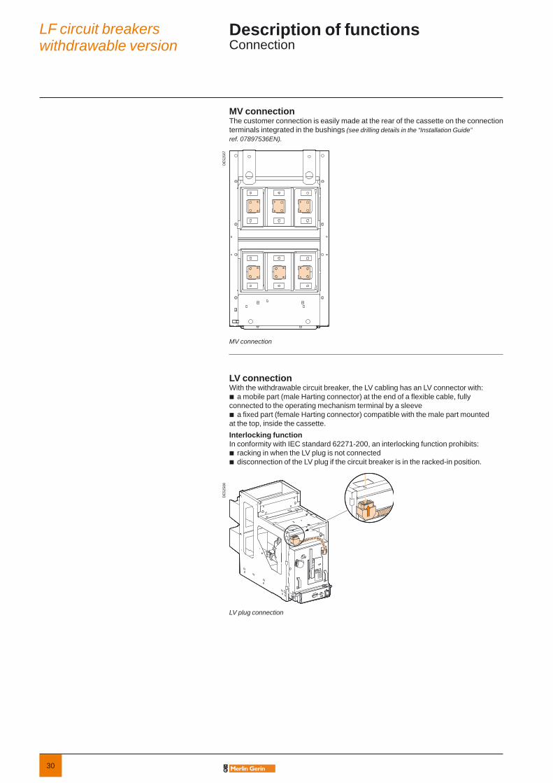
MV connectionThe customer connection is easily made at the rear of the cassette on the connection terminals integrated in the bushings (see drilling details in the “Installation Guide” ref. 07897536EN).
MV connection
LV connectionWith the withdrawable circuit breaker, the LV cabling has an LV connector with:
a mobile part (male Harting connector) at the end of a fl exible cable, fully connected to the operating mechanism terminal by a sleeve
a fi xed part (female Harting connector) compatible with the male part mounted at the top, inside the cassette.Interlocking functionIn conformity with IEC standard 62271-200, an interlocking function prohibits:
racking in when the LV plug is not connecteddisconnection of the LV plug if the circuit breaker is in the racked-in position.
LV plug connection
b
b
bb
DE5
2507
DE5
2508
LF circuit breakerswithdrawable version
Description of functionsConnection
31
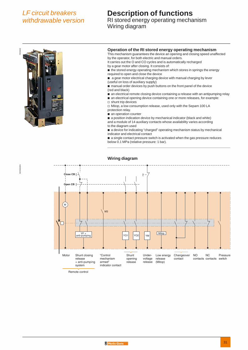
Operation of the RI stored energy operating mechanismThis mechanism guarantees the device an opening and closing speed unaffected by the operator, for both electric and manual orders. It carries out the O and CO cycles and is automatically recharged by a gear motor after closing. It consists of:
the stored energy operating mechanism which stores in springs the energy required to open and close the device
a gear motor electrical charging device with manual charging by lever(useful on loss of auxiliary supply)
manual order devices by push buttons on the front panel of the device (red and black)
an electrical remote closing device containing a release with an antipumping relayan electrical opening device containing one or more releases, for example:shunt trip devicesMitop, a low consumption release, used only with the Sepam 100 LA
protection relay.an operation counter a position indication device by mechanical indicator (black and white)
and a module of 14 auxiliary contacts whose availability varies according to the diagram used
a device for indicating “charged” operating mechanism status by mechanical indicator and electrical contact
a single contact pressure switch is activated when the gas pressure reduces below 0.1 MPa (relative pressure: 1 bar).
Wiring diagram
b
b
b
bbvv
bb
b
b
PE
5582
6D
E55
692E
N
LF circuit breakerswithdrawable version
Description of functionsRI stored energy operating mechanismWiring diagram
Pressureswitch
NO contacts
Changeovercontact
NC contacts
M
YF +anti-pumping
Motor Shunt closingrelease+ anti-pumpingsystem
Remote control
Shunt openingrelease
Under-voltagerelease
Low energyrelease(Mitop)
Close CB
Open CB
YM
M3
Mitop
“Control mechanism armed” indicator contact
YO1 YO2

32
CompositionThe opening circuit can be produced using the following components:
shunt opening release (on energizing) (YO1)second shunt opening release (on energizing) (YO2)undervoltage release (YM)low energy release (Mitop).
Note: see the table of the releases’ combinations, “Order form” page.
Shunt opening release (YO1 and YO2)Energizing this unit causes instant opening of the circuit breaker.
CharacteristicsPower supply See “Order form” pageThreshold V AC 0.85 to 1.1 Ur
V DC 0.7 to 1.1 UrConsumption V AC 160 VA
V DC 50 W
Undervoltage release (YM)This release unit causes the systematic opening of the circuit breaker when itssupply voltage drops below a value less than 35% of the rated voltage, even if thisdrop is slow and gradual. It can open the circuit breaker between 35% and 70% ofits rated voltage. If the release unit is not supplied power, manual or electrical closingof the circuit breaker is impossible. Closing of the circuit breaker is possible whenthe supply voltage of the release unit reaches 85% of its rated voltage.
CharacteristicsPower supply See “Order form” pageThreshold Opening 0.35 to 0.7 Ur
Closing 0.85 UrConsumption Triggering V AC 400 VA
V DC 100 WLatched V AC 100 VA
V DC 10 W
Low energy release (Mitop)This specifi c release unit comprises a low consumption unit and is specifi cally used for Sepam 100LA self-powered relays.
CharacteristicsPower supply Direct current Threshold 0.6 A < I < 3 A
Any tripping due to the Mitop release unit is momentarily indicated by an SDE type changeover contact (option).
bbbb
DE
5570
1EN
DE
6009
4D
E60
089
DE
6009
1
Operating mechanism
Shunt opening release (1)
Undervoltage release (2)
Low energy release (3)
LF circuit breakerswithdrawable version
Description of functionsOpening circuit
(1) or (3)(2)

33
DE
5611
5D
E60
093
DE
6015
1
Operating mechanism
Electrical motor and gearing (4)
Shunt closing release (5)
FunctionIn its basic version, the circuit breaker comprises a remote control mechanism for remote circuit breaker opening and closing.
CompositionThe remote control mechanism comprises:
an electrical motor with gearinga shunt closing release (YF) combined with an anti-pumping devicean operation counter.
Electrical motor with gearing (M)The electrical motor carries out the automatic rearming of the stored energy unit as soon as the circuit breaker is closed. This allows the instant reclosing of the device after opening. The arming lever is only used as a backup operating mechanism in the case of the absence of the auxiliary power supply.The M3 contact indicates the end of arming operations.
CharacteristicsPower supply See “Order form” pageThreshold V AC/V DC 0.85 to 1.1 UrConsumption V AC 380 VA
V DC 380 W
Shunt closing release (YF)This release allows the remote closing of the circuit breaker when the operating mechanism is armed.
CharacteristicsPower supply See “Order form” pageThreshold V AC 0.85 to 1.1 Ur
V DC 0.85 to 1.1 UrConsumption V AC 160 VA
V DC 50 W
The shunt closing release is combined with an anti-pumping relay that enables priority to be given to opening in the case of a permanent closing order. This thus avoids the device being caught in an uncontrolled opening-closing cycle.
bbb
(4)
(5)
LF circuit breakerswithdrawable version
Description of functionsRemote control

34
DE
6008
7
Operation counter (6)
DE
5611
6D
E60
124
Operating mechanism
Kit to lock the circuit breaker in the “open” position (8)
Operation counterThe operation counter is visible on the front panel.It displays the number of switching cycles (CO) that the device has carried out.
“Open/closed” auxiliary contacts These auxiliary contacts indicate the “open” or “closed” position of the circuit breaker.The number of contacts available depends on the options chosen on the operating mechanism.In the basic confi guration, the circuit breaker operating mechanism comprises a total of:
5 normally closed contacts (NC)5 normally open contacts (NO)1 changeover contact (CHG).
The usage mode for auxiliary contacts is given in the following table:
OptionsNC contact NO contact
Shunt opening release (each one) 0 1 Undervoltage release 0 0Low energy release (Mitop) 0 0
To know the fi nal number of available contacts, you must deduct the total number of contacts included in the circuit breaker (5 NC + 5 NO + 1 CHG), from the number of contacts used indicated in the table above.E.g.: a circuit breaker equipped with a remote control and a shunt release has the following contacts available: 5 NC + 4 NO + 1 CHG. With an undervoltage release instead of a shunt release, this circuit breaker would have the following available contacts:5 NC + 5 NO + 1 CHG.
Shunt opening release combination1st release
2nd release
Shunt opening release YO1
Undervoltage release YM
Mitop
Without 5NC + 4NO + 1CHG 5NC + 5NO+ 1CHG 5NC + 5NO + 1CHGShunt opening release YO2
5NC + 3NO + 1CHG 5NC + 4NO+ 1CHG 5NC + 4NO + 1CHG
Undervoltage release YM
5NC + 4NO + 1CHG 5NC + 5NO + 1CHG
Mitop 5NC + 4NO + 1CHG 5NC + 5NO + 1CHG
Contacts characteristicsRated current 10 ABreaking capacity AC 220 V (cos ϕ ≥ 0.3) 1 A
DC 110/220 V (L/R ≤ 0.02 s) 0.3 A
Locking the circuit breaker in the “open” positionThis key-operated device allows the circuit breaker to be locked in the “open” position. The circuit breaker is locked in the open position by blocking the opening push button in the “engaged” position.Locking is achieved using a Profalux or Ronis captive key type keylock.
bbb(8)
(6) (7)
DE
5195
3
Auxiliary contacts (7)
LF circuit breakerswithdrawable version
Description of functionsIndication and locking/interlocking

35
Parts Circuit breaker positionsInsertion
Extraction
Racking-in
Racking-out
Removed Disconnected Test position Service
1 - Cradle Fool-proof protection (1)
Anti-drop (2)
No opening shutters
Shutters padlocking possible
2 - LV plug Disconnected Door closing impossible
Connected No unplugging (5)
3 - Circuit breaker Closed Auto-discharge function (3)
No racking-in No racking-out
Open No closing
Open position circuit breaker locking available (3)
4 - Switchboard door Open No racking-in
Closed No door opening (4)
5 - Earthing switch Open No earthing switch closing
Closed No racking-in
(1) This protection mechanism ensures that the performance levels of the circuit breaker correspond with those of the cassette.(2) Device that prevents the circuit breaker from dropping when extracted from the cassette.The device can be either unlocked manually or when the extraction rig is put in position.(3) Option.(4) Interlocking device to be fi tted to the cubicle door.(5) Because the door is closed.
This table describes the safety functions available on the withdrawable version of the LF circuit breaker.How to use the tableEach of the boxes describes the functional status of each circuit breaker position and the associated parts:
Possible status
Possible status, impossible operation
Impossible status
LF circuit breakerswithdrawable version
Description of functionsSafety functions
36
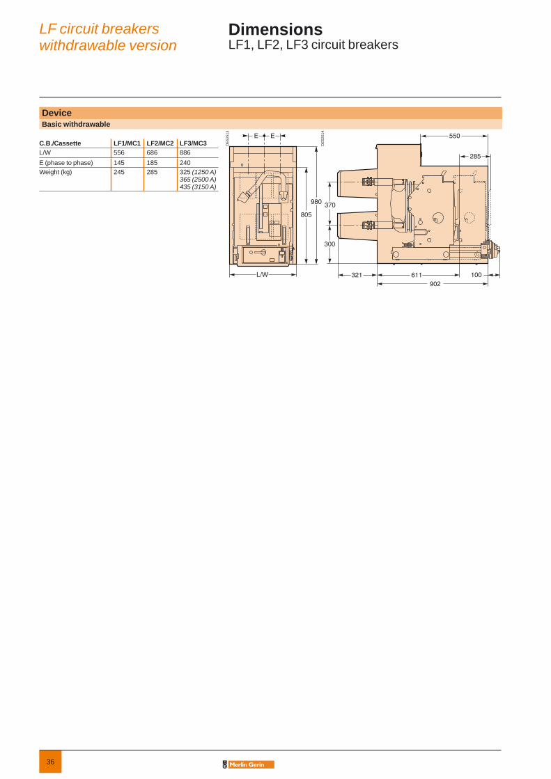
DeviceBasic withdrawable
DE
5251
3
L/W
E E
980
805
DE
5251
4
300
370
611902
285
321
550
100
C.B./Cassette LF1/MC1 LF2/MC2 LF3/MC3L/W 556 686 886E (phase to phase) 145 185 240Weight (kg) 245 285 325 (1250 A)
365 (2500 A)435 (3150 A)
LF circuit breakerswithdrawable version
DimensionsLF1, LF2, LF3 circuit breakers
37
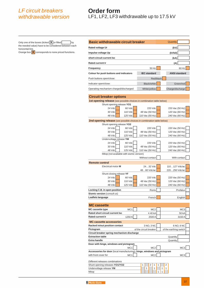
Different releases combinationsShunt opening releases YO1/YO2 1 2 1 1 2Undervoltage release YM 1 1 1 1Mitop 1 1
Only one of the boxes (ticked X or fi lled bythe needed value) have to be considered between each horizontal line. Orange box X corresponds to none priced functions.
Basic withdrawable circuit breaker Quantity
Rated voltage Ur (kV)
Impulse voltage Up (kVbil)
short-circuit current Isc (kA)
Rated current Ir (A)
Frequency 50 Hz 60 Hz
Colour for push buttons and indicators IEC standard ANSI standard
Push buttons open/close: Red/black
Indicator open/close: Black/white Green/red
Operating mechanism charged/discharged: White/yellow Charge/discharge
Circuit breaker options1st opening release (see possible choices in combination table below)
Shunt opening release YO124 Vdc 60 Vdc 220 Vdc 220 Vac (50 Hz) 30 Vdc 110 Vdc 48 Vac (50 Hz) 120 Vac (60 Hz) 48 Vdc 125 Vdc 110 Vac (50 Hz) 240 Vac (60 Hz)
2nd opening release (see possible choices in combination table below)Shunt opening release YO2
24 Vdc 60 Vdc 220 Vdc 220 Vac (50 Hz) 30 Vdc 110 Vdc 48 Vac (50 Hz) 120 Vac (60 Hz) 48 Vdc 125 Vdc 110 Vac (50 Hz) 240 Vac (60 Hz)
Undervoltage release YM24 Vdc 60 Vdc 220 Vdc 220 Vac (50 Hz) 30 Vdc 110 Vdc 48 Vac (50 Hz) 120 Vac (60 Hz) 48 Vdc 125 Vdc 110 Vac (50 Hz) 240 Vac (60 Hz)
Mitop (not available with sismic version)Without contact With contact
Remote controlElectrical motor M 24…32 Vdc 110…127 Vdc/ac
48…60 Vdc/ac 220…250 Vdc/ac Shunt closing release YF
24 Vdc 60 Vdc 220 Vdc 220 Vac (50 Hz) 30 Vdc 110 Vdc 48 Vac (50 Hz) 120 Vac (60 Hz) 48 Vdc 125 Vdc 110 Vac (50 Hz) 240 Vac (60 Hz)
Locking C.B. in open position Ronis Profalux Sismic version (consult us) Leafl ets language French English
MC cassetteMC cassette type MC1 MC2 MC3 Rated short circuit current Isc y 40 kA 50 kA Rated current Ir 1250 A 2500 A 3150 A
MC cassette accessoriesRacked in/out position contact 3 NO, 3 NC 6 NO, 6 NC Pictogram of the circuit breaker of the earthing switch Circuit breaker spring mechanism discharge Extraction table Quantity Extra handle Quantity Door with hinge, windows and pictogram
MC1 MC2 MC3 Accessories for door (local manufacturing): hinge, windows and pictogramwith front cover for MC1 MC2 MC3
LF circuit breakerswithdrawable version
Order formLF1, LF2, LF3 withdrawable up to 17.5 kV

38
This international site allows you to access all the Merlin Gerin products in just 2 clicks via comprehensive range data-sheets, with direct links to:
complete library: technical documents, catalogs, FAQs, brochures…
selection guides from the e-catalog.
product discovery sites and their Flash animations.
You will also fi nd illustrated overviews, news to which you can subscribe, the list of country contacts…
b
b
b
Training allows you to acquire the Merlin Gerin expertise (installation design, work with power on, etc.) for increased effi ciency and a guarantee of improved customer service.The training catalogue includes beginner’s courses in electrical distribution, knowledgeof MV and LV switchgear, operation and maintenance of installations, design of LV installations to give but a few examples.

39
LFP circuit breakersLF circuit breakers
General presentation 6Panorama 9LF circuit breakers fixed version 11LF circuit breakers withdrawable version 23
Presentation 41General characteristics 42Description of functions 43RI stored energy operating mechanism 43Wiring diagram 43Opening circuit 44Remote control 45Indication and locking/interlocking 46
Dimensions 47Order form 48

40
41
PE
5582
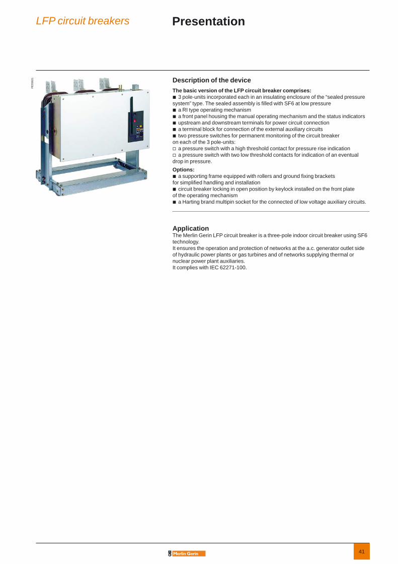
1 Description of the deviceThe basic version of the LFP circuit breaker comprises:
3 pole-units incorporated each in an insulating enclosure of the “sealed pressure system” type. The sealed assembly is fi lled with SF6 at low pressure
a RI type operating mechanism a front panel housing the manual operating mechanism and the status indicators upstream and downstream terminals for power circuit connection a terminal block for connection of the external auxiliary circuits two pressure switches for permanent monitoring of the circuit breaker
on each of the 3 pole-units:a pressure switch with a high threshold contact for pressure rise indicationa pressure switch with two low threshold contacts for indication of an eventual
drop in pressure.Options:
a supporting frame equipped with rollers and ground fi xing brackets for simplifi ed handling and installation
circuit breaker locking in open position by keylock installed on the front plate of the operating mechanism
a Harting brand multipin socket for the connected of low voltage auxiliary circuits.
ApplicationThe Merlin Gerin LFP circuit breaker is a three-pole indoor circuit breaker using SF6 technology. It ensures the operation and protection of networks at the a.c. generator outlet side of hydraulic power plants or gas turbines and of networks supplying thermal or nuclear power plant auxiliaries. It complies with IEC 62271-100.
b
bbbbb
vv
b
b
b
LFP circuit breakers Presentation

42
Electrical characteristics according to IEC 62271-100
Rated voltage Ur kV 50/60 Hz 12 15 17.5Insulation voltage- power frequency withstand Ud kV 50 Hz 1min 28 (*) 38 (*) 38 (*)- lightning impulse withstand Up kV peak 75 95 (*) 95 (*)Rated current Ir A 5000 b b b b b
Short circuit current Isc kA 40 50 40 25 31.5Asymmetry (%) 50 30 30 100 30
Short time withstand current Ik/tk kA/3 s 40 50 40 25 31.5Short-circuit making current Ip kA peak 50 Hz 100 125 100 63 79Rated switching sequence O-3 min-CO-3 min-CO b b b b b
Operating times Opening ms 48Breaking ms 70Closing ms 65
Service temperature T °C –25 to +40
(*) For higher values: consult usb Available.
PE
5582
1
LFP circuit breakers General characteristics
43
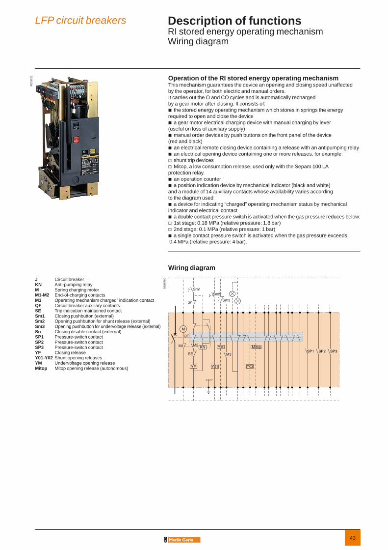
Operation of the RI stored energy operating mechanismThis mechanism guarantees the device an opening and closing speed unaffected by the operator, for both electric and manual orders. It carries out the O and CO cycles and is automatically recharged by a gear motor after closing. It consists of:
the stored energy operating mechanism which stores in springs the energy required to open and close the device
a gear motor electrical charging device with manual charging by lever(useful on loss of auxiliary supply)
manual order devices by push buttons on the front panel of the device (red and black)
an electrical remote closing device containing a release with an antipumping relayan electrical opening device containing one or more releases, for example:shunt trip devicesMitop, a low consumption release, used only with the Sepam 100 LA
protection relay.an operation counter a position indication device by mechanical indicator (black and white)
and a module of 14 auxiliary contacts whose availability varies according to the diagram used
a device for indicating “charged” operating mechanism status by mechanical indicator and electrical contact
a double contact pressure switch is activated when the gas pressure reduces below:1st stage: 0.18 MPa (relative pressure: 1.8 bar)2nd stage: 0.1 MPa (relative pressure: 1 bar)a single contact pressure switch is activated when the gas pressure exceeds
0.4 MPa (relative pressure: 4 bar).
Wiring diagram
b
b
b
bbvv
bb
b
bvvb
PE
5582
6
DE
5578
0JKNMM1-M2M3QFSESm1Sm2Sm3SnSP1SP2SP3YFY01-Y02YMMitop
Circuit breakerAnti-pumping relaySpring charging motorEnd-of-charging contactsOperating mechanism charged” indication contactCircuit breaker auxiliary contacts Trip indication maintained contactClosing pushbutton (external)Opening pushbutton for shunt release (external)Opening pushbutton for undervoltage release (external)Closing disable contact (external)Pressure-switch contactPressure-switch contactPressure-switch contactClosing releaseShunt opening releasesUndervoltage opening releaseMitop opening release (autonomous)
LFP circuit breakers Description of functionsRI stored energy operating mechanismWiring diagram
44
CompositionThe opening circuit can be produced using the following components:
shunt opening release (on energizing) (YO1)second shunt opening release (on energizing) (YO2)undervoltage release (YM)low energy release (Mitop).
Note: see the table of the releases’ combinations “Order form” page.
Shunt opening release (YO1 and YO2)Energizing this unit causes instant opening of the circuit breaker.
CharacteristicsPower supply See “Order form” pageThreshold V AC 0.85 to 1.1 Ur
V DC 0.7 to 1.1 UrConsumption V AC 160 VA
V DC 50 W
Undervoltage release (YM)This release unit causes the systematic opening of the circuit breaker when its supply voltage drops below a value less than 35% of the rated voltage, even if this drop is slow and gradual. It can open the circuit breaker between 35% and 70% of its rated voltage. If the release unit is not supplied power, manual or electrical closing of the circuit breaker is impossible. Closing of the circuit breaker is compulsory when the supply voltage of the release unit reaches 85% of its rated voltage.
CharacteristicsPower supply See “Order form” pageThreshold Opening 0.35 to 0.7 Ur
Closing 0.85 UrConsumption Triggering V AC 400 VA
V DC 100 WLatched V AC 100 VA
V DC 10 W
Low energy release (Mitop)This specifi c release unit comprises a low consumption unit and is specifi cally used for Sepam 100LA self-powered relays.
CharacteristicsPower supply Direct currentThreshold 0.6 A < I < 3 A
Any tripping due to the Mitop release unit is momentarily indicated by an SDE type changeover contact.
bbbb
DE
5570
1EN
DE
6009
4D
E60
089
DE
6009
1
Operating mechanism
Shunt opening release (1)
Undervoltage release (2)
Low energy release (3)
LFP circuit breakers Description of functionsOpening circuit
(1) or (3)(2)

45
DE
5570
2D
E60
093
DE
6015
1D
E60
087
(4)
(5)(6)
Operating mechanism
Electrical motor and gearing (4)
Shunt closing release (5)
Operation counter (6)
FunctionRemote control enables the remote opening and closing of the circuit breaker.
CompositionThe remote control mechanism comprises:
an electrical motor with gearing a shunt closing release (YF) combined with an anti-pumping devicean operation counter.
Electrical motor with gearing (M)The electrical motor arms and re-arms the stored energy unit as soon as the circuit breaker is closed. This allows the instant closing of the device after opening. The arming lever is only used as a back-up operating mechanism in the case of any auxiliary power supply. The M3 contact indicates the end of arming operations.
CharacteristicsPower supply See “Order form” pageThreshold V AC/V DC 0.85 to 1.1 UrConsumption V AC 380 VA
V DC 380 W
Shunt closing release (YF)This allows the remote closing of the circuit breaker when the operating mechanism is armed.
CharacteristicsPower supply See “Order form” pageThreshold V AC 0.85 to 1.1 Ur
V DC 0.85 to 1.1 UrConsumption V AC 160 VA
V DC 50 W
The anti-pumping relay enables the guaranteeing of opening priority in the case of a permanent closing order. This therefore avoids the device being caught in a uncontrolled opening-closing loop.
Operation counterThe operation counter is visible on the front panel.It displays the number of switching cycles (CO) that the device has carried out.
bbb
LFP circuit breakers Description of functionsRemote control

46
“Open/closed” auxiliary contacts The number of contacts available depends on the options chosen on the operating mechanism.In the basic confi guration, the circuit breaker’s operating mechanism comprises a total of:
5 normally closed contacts (NC)5 normally open contacts (NO)1 changeover contact (CHG).
The usage procedure for auxiliary contacts is given in the following table:
OptionsNC contact NO contact
Shunt opening release (each one) 0 1Undervoltage release 0 0Low energy release (Mitop) 0 0
In order to know the fi nal number of available contacts, you must deduct the total number of contacts included in the circuit breaker (5 NC + 5 NO + 1 CHG), the number of contacts used given in the table above.E.g.: a circuit breaker equipped with a remote control and a shunt trip unit has the following available contacts: 5 NC + 4 NO + 1 CHG. With a undervoltage release instead of the shunt trip, this circuit breaker would have the following available contacts: 5 NC + 5 NO + 1 CHG.
Shunt opening release combination1st release
2nd release
Shunt opening release YO1
Undervoltage release YM
Mitop
Without 5NC + 4NO + 1CHG 5NC + 5NO+ 1CHG 5NC + 5NO + 1CHGShunt opening release YO2
5NC + 3NO + 1CHG 5NC + 4NO+ 1CHG 5NC + 4NO + 1CHG
Undervoltage release YM
5NC + 4NO + 1CHG 5NC + 5NO + 1CHG
Mitop 5NC + 4NO + 1CHG 5NC + 5NO + 1CHG
Locking the circuit breaker in the “open” positionThis key-operated device allows the circuit breaker to be locked in the “open” position. The circuit breaker is locked in the open position by blocking the opening push button in the “engaged” position.Locking is achieved using a Profalux or Ronis captive key type keylock.
bbb
DE
5569
0D
E60
124
Operating mechanism
Keylocking kit (8)
DE
5195
3
Auxiliary contacts (7)
(8)
(7)
LFP circuit breakers Description of functionsIndication and locking/interlocking
47
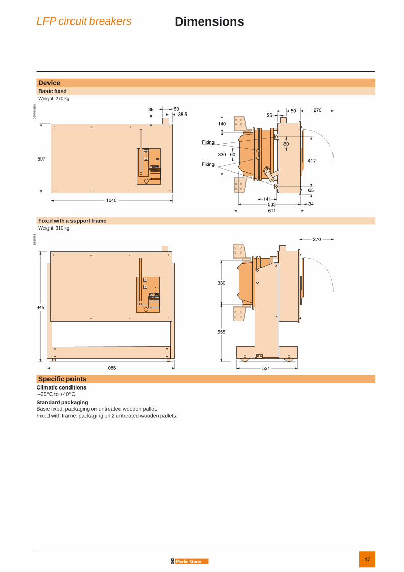
DeviceBasic fi xedWeight: 270 kg
DE
5578
2EN
597 ofo
ofo
503838.5
1040
330
34
270
533
5025
60
80
65
Fixing
611
140
417
141
Fixing
Fixed with a support frameWeight: 310 kg
DE
5578
3
ofo
ofo
330
270
521
945
555
1086
Specifi c pointsClimatic conditions –25°C to +40°C.Standard packagingBasic fi xed: packaging on untreated wooden pallet.Fixed with frame: packaging on 2 untreated wooden pallets.
LFP circuit breakers Dimensions

48
Basic fi xed circuit breaker Quantity
Rated voltage Ur (kV)
Impulse voltage Up (kVbil)
short-circuit current Isc (kA)
Rated current Ir (A)
Frequency 50 Hz 60 Hz
Colour for push buttons and indicators IEC standard ANSI standard
Push buttons open/close: Red/black
Indicator open/close: Black/white Green/red
Operating mechanism charged/discharged: White/yellow Charge/discharge
Circuit breaker options1st opening release (see possible choices in combination table below)
Shunt opening release YO124 Vdc 60 Vdc 220 Vdc 220 Vac (50 Hz) 30 Vdc 110 Vdc 48 Vac (50 Hz) 120 Vac (60 Hz) 48 Vdc 125 Vdc 110 Vac (50 Hz) 240 Vac (60 Hz)
2nd opening release (see possible choices in combination table below)Shunt opening release YO2
24 Vdc 60 Vdc 220 Vdc 220 Vac (50 Hz) 30 Vdc 110 Vdc 48 Vac (50 Hz) 120 Vac (60 Hz) 48 Vdc 125 Vdc 110 Vac (50 Hz) 240 Vac (60 Hz)
Undervoltage release YM24 Vdc 60 Vdc 220 Vdc 220 Vac (50 Hz) 30 Vdc 110 Vdc 48 Vac (50 Hz) 120 Vac (60 Hz) 48 Vdc 125 Vdc 110 Vac (50 Hz) 240 Vac (60 Hz)
MitopWithout contact With contact
Remote controlElectrical motor M 24…32 Vdc 110…127 Vdc/ac
48…60 Vdc/ac 220…250 Vdc/ac Shunt closing release YF
24 Vdc 60 Vdc 220 Vdc 220 Vac (50 Hz) 30 Vdc 110 Vdc 48 Vac (50 Hz) 120 Vac (60 Hz) 48 Vdc 125 Vdc 110 Vac (50 Hz) 240 Vac (60 Hz)
Low voltage wiring connection Male plug (1.2 m) Female socket (2 m) Locking C.B. in open position Ronis Profalux Support frame Leafl ets language French English
Different releases combinationsShunt opening releases YO1/YO2 1 2 1 1Undervoltage release YM 1 1 1Mitop 1 1 1
Only one of the boxes (ticked X or fi lled bythe needed value) have to be considered between each horizontal line. Orange box X corresponds to none priced functions.
LFP circuit breakers Order formLFP up to 17.5 kV


AMTED397052EN 02-2007
Schneider Electric Industries SAS
AR
T786
54 ©
200
7 - S
chne
ider
Ele
ctric
- A
ll rig
hts
rese
rved
As standards, specifications and designs develop from time to time, always ask for confirmation of the information given in this publication.
Production: Schneider ElectricPhotos: Schneider ElectricPrinting: Imprimerie du Pont de Claix/JPF - Made in France
This document has been printed on ecological paper
89, boulevard Franklin RooseveltF - 92500 Rueil-Malmaison (France)Tel.: +33 (0)1 41 29 85 00
http://www.schneider-electric.comhttp://www.merlin-gerin.com
Related Documents