MURDOCH RESEARCH REPOSITORY This is the author’s final version of the work, as accepted for publication following peer review but without the publisher’s layout or pagination. The definitive version is available at : http://dx.doi.org/10.1016/j.epsr.2014.08.010 Shahnia, F., Chandrasena, R.P.S., Ghosh, A. and Rajakaruna, S. (2014) Application of DSTATCOM for surplus power circulation in MV and LV distribution networks with single-phase distributed energy resources. Electric Power Systems Research, 117 . pp. 104-114. http://researchrepository.murdoch.edu.a/32525/ Copyright: © 2014 Elsevier B.V. It is posted here for your personal use. No further distribution is permitted.

Welcome message from author
This document is posted to help you gain knowledge. Please leave a comment to let me know what you think about it! Share it to your friends and learn new things together.
Transcript

MURDOCH RESEARCH REPOSITORY
This is the author’s final version of the work, as accepted for publication following peer review but without the publisher’s layout or pagination.
The definitive version is available at :
http://dx.doi.org/10.1016/j.epsr.2014.08.010
Shahnia, F., Chandrasena, R.P.S., Ghosh, A. and Rajakaruna, S. (2014) Application of DSTATCOM for surplus power circulation in MV and LV
distribution networks with single-phase distributed energy resources. Electric Power Systems Research, 117 . pp. 104-114.
http://researchrepository.murdoch.edu.a/32525/
Copyright: © 2014 Elsevier B.V. It is posted here for your personal use. No further distribution is permitted.

NOTICE: this is the author’s version of a work that was accepted for publication in the journal Electric Power Systems Research. Changes resulting from the publishing process, such as peer review, editing, corrections, structural formatting, and other quality control mechanisms may not be reflected in this document. Changes may have been made to this work since it was submitted for publication. A definitive version was subsequently published in the journal Electric Power Systems Research, Vol.117 (2014). DOI: http://doi.org/10.1016/j.epsr.2014.08.010

Page 1
Application of DSTATCOM for Surplus Power Circulation in MV and LV
Distribution Networks with Single-phase Distributed Energy Resources
Farhad Shahnia1, Ruwan P.S. Chandrasena
2, Arindam Ghosh
1 and Sumedha Rajakaruna
2
1 Center of smart grid and sustainable power systems, Curtin University, Perth, Australia
2 Department of Electrical and Computer Engineering, Curtin University, Perth, Australia
(Corresponding Author: [email protected], +61 432 020 732)
Abstract––Single-phase distributed energy resources (DERs), such as rooftop photovoltaic arrays, are usually
installed based on the need and affordability of clients without any regard to the power demand of the con-
nected phase of a three-phase system. It might so happen that the power generation in a particular phase is
more than its load demand. This may cause a reverse power flow in a particular phase, especially in a three-
phase, four-wire distribution system. If now the load demand in the other two phases is more than their re-
spective generations, then these two phases will see a forward power flow, while there will be a reverse pow-
er flow in the third phase. This will create severe unbalance in the upstream network. In this paper, a distribu-
tion static compensator (DSTATCOM) is used to circulate the excess generation from one phase to the others
such that a set of balanced currents flow from or into the upstream network. Two different topologies of
DSTATCOM are proposed in this paper for the low and medium voltage feeders. Two different power circu-
lation strategies are developed for this purpose. Furthermore, a suitable feedback scheme is developed for
each topology for power converter control. The performance of the proposed topologies and the control
schemes for the DSTATCOM is evaluated through computer simulation studies using PSCAD/EMTDC.
Index Terms––Distribution Static Compensator (DSTATCOM), Distributed Energy Resource (DER), Power
circulation
1. Introduction
Distributed Generation on both low voltage (LV) and medium voltage (MV) feeders has increased rapidly
over the last decade mainly due to the recent global efforts to minimize carbon emissions and to increase
power system efficiency and reliability [1–6]. Solar photovoltaic (PV) is the most popular form of renewable

Page 2
distributed generation (DG), especially in countries with abundance of sunlight and government subsidies for
renewable energy generation [7–13]. Other forms of DGs, such as micro wind turbines, fuel cells, micro-
turbines and bio-diesel engines, are also been deployed in various parts of the world. Furthermore, electric
vehicles (EVs) are expected to make a significant percentage of the load in the near future [14–15]. At the
present time, the EVs only charge their batteries by drawing power from the grid in grid-to-vehicle (G2V)
mode [16]. However, as the battery technology improves, EVs can work as DGs, where they supply power
from the batteries to the grid in vehicle-to-grid (V2G) mode [17–18]. Moreover, energy storage devices such
as battery banks and flywheels are expected to penetrate into the grid to regulate the energy fluctuations aris-
ing from intermittent renewable sources [19–22]. All these different generating sources and energy storages
that can feed power to the grid are collectively referred to as distributed energy resource (DER).
Despite the well-known advantages of DERs such as reduced transmission losses, increased reliability etc.,
their introduction in LV feeders has some drawbacks in terms of power quality that need to be addressed
[23–25]. Some of these are voltage/current unbalance among phases and voltage rise [26]. Although the utili-
ty grid supplies balanced voltages to the LV feeders, unequal distribution of single-phase DERs may create
some current unbalance in LV feeders [27]. For example, in Australia, single-phase solar PVs are increasing-
ly getting connected to LV feeders in a random fashion. Their ratings can also vary. This can ultimately af-
fect the upstream MV feeder since large unbalanced currents can be drawn from it.
One method of eliminating the voltage unbalance and improving the voltage profile in the distribution
feeders is applying a new control technique for the DERs’ converters such that not only power transfer is fa-
cilitated but also power quality is enhanced in the network. As an example, in [27], a new converter control
topology is proposed for the single-phase PV converters. Alternatively, a droop control technique is proposed
for improving the voltage profile in LV feeders by the help of PV converters in [28]. Similarly, for three-
phase DERs, a converter control strategy is proposed in [29] such that not only it facilitates the power flow
from the DER to the network but it also compensates the voltage at its terminals although the network loads
are unbalanced.
On the other hand, custom power devices (CPDs) have already been proven to be effective for alleviating
power quality problems [30]. Different configurations, topologies and control algorithms are already pro-

Page 3
posed for them. As an example, in [31], it is shown that distribution static compensators (DSTATCOM) and
dynamic voltage regulators (DVR) are effective types of CPDs for power quality enhancement in LV feeders.
The DSTATCOM and DVR in [31] are composed of three single-phase converters connected to the same DC
bus. In [32], it is shown that unified power quality conditioner (UPQC), an another type of CPDs, which is
composed of two back-to-back connected series and parallel converters, can enhance the power quality in
MV feeders. In [33–34], a UPQC configuration is utilized for the interfacing converter of a DER to enable
active power flow as well as voltage unbalance improvement in the network. In [35] it is shown that an open
UPQC, where the series and parallel converters are located with some distance and are not connected back-
to-back, can be used in MV/LV substations to enhance the power quality. In [36–37], it is shown that an in-
terline DVR and interline UPQC can facilitate power flow from one MV feeder to another MV feeder as well
as enhancing power quality in the feeders.
Among the above discussed CPDs, DSTATCOM is highly successful in different power quality issues
such as improving power factor by reactive power injection, controlling the voltage at the interconnected bus
and suppressing harmonic currents [38–40]. Some of these issues such as harmonics and power losses have
already been investigated in the context of DERs. It has been shown in [41] that a DSTATCOM can reduce
voltage unbalance in a distribution feeder. Furthermore, the best possible location for installing a DSTAT-
COM for optimum performance was also investigated in [31].
Since the single-phase DERs are placed randomly among the phases, it is possible that the generation in a
particular phase exceeds the load demand in that phase. Under such a condition, the surplus phase power will
feed back towards the distribution transformer in the LV feeders. Rooftop PVs are a good example of the
single-phase DERs that generate the maximum amount of power at midday when the residential load demand
is at its minimum. Hence, the LV feeders in such cases can experience a reverse power flow in one or more
phases. It is to be noted that this reverse power flow is a steady-state phenomenon and is not a transient issue.
Assuming a residential area with a high penetration level of PVs, it can be expected that the reverse power
flow will not only be observed in the LV feeders but it will also be observed in the MV feeder supplying
these LV feeders. In [41–42], application of a DSTATCOM, connected to the MV feeder, is been considered
for circulating surplus phase power from one phase to another. This is a new application for DSTATCOM.

Page 4
A DSTATCOM can be connected to LV as well as MV feeders. The main advantage of installing a
DSTATCOM in an LV feeder is the elimination of the reverse power flow at the point of emergence of the
problem. This is the most effective way to prevent the reverse power flow before it being injected to the MV
side. However, installation of a few DSTATCOMs in several adjoining LV feeders, supplied by the same
MV line, is not cost-effective. Hence, reduction in the initial investment costs is the main advantage of in-
stalling a DSTATCOM in the MV feeder. In general, several criteria can be considered in choosing the con-
nection of DSTATCOM to a LV or MV feeder such as:
Economic concerns: The cost of a DSTATCOM is highly dependent on its rating. Similar to other electrical
devices, this cost increases significantly by the increase in the DSTATCOM rating. Hence, economic anal-
yses can lead to choosing among the two options of installing one DSTATCOM, with a higher rating, in the
MV feeder or several DSTATCOMs, each with a smaller rating, in the LV feeders.
The level and frequency of reverse power flow in the feeder: The reverse power flow may be experienced
more frequently with higher percentage in the LV feeders while it may neither be very frequent nor a high
percentage in the MV feeders. Therefore, the level of reverse power flow in MV line can sometimes be in-
significant while it is significant in some LV lines.
Reliability concerns: Failure of a DSTATCOM in a LV feeder may only interrupt the power supply to a few
customers in the feeder, however; its failure in a MV feeder may result in power interruption to a larger
number of customers of the MV feeder.
Operational and maintenance (O&M) concerns: A DSTATCOM installed in a LV feeder will have less
O&M costs and lower hazards for the personnel under hot line practices, in comparison to those of the MV
installation.
The DC link of the DSTATCOM, used in [31, 40–42], consists of a battery (i.e. a DC source). Therefore,
the DSTATCOM can operate like an uninterruptable power supply (UPS) where it can exchange active as
well as reactive power with the feeder. In this paper, to minimize the initial and O&M costs of a DSTAT-
COM, a DC capacitor is used instead of the battery. The main difference in this case is that the DSTATCOM
only exchanges reactive power with the feeder to facilitate current circulation from one phase to another.
However, the voltage across the capacitor should be controlled to a rated value by drawing active power from

Page 5
the AC network. Unless the voltage across the DC capacitor regulated at its rated value, the DSTATCOM is
not able to produce the desired output and will fail to circulate the reverse flowing power/current.
Two different topologies are considered for the DSTATCOM in this paper– one when used in LV feeder
and the other is used in MV feeder. The positioning of the boosting transformer in the output of the DSTAT-
COM is different for MV and LV applications. This changes the filter characteristic in the output of the
DSTATCOM. In this paper, it has been shown that voltage control strategy is suitable for LV applications
from the output passive filter arrangement point of view. On the other hand, it is shown that current control
strategy is well suited for MV applications, from the same point of view.
The current and voltage output references of the DSTATCOM are generated such that a set of balanced
currents are drawn from the upstream side, while facilitating the circulation of reverse flowing power among
the phases. In addition, the used topology for LV application provides a reliable path between the phases for
off-grid applications. Hence, the single-phase DERs, controlled in droop, can manage the power demand of
the three-phase network when the LV feeder is isolated from the upstream side, irrespective of the phase to
which they are connected. This application is not considered in [31, 40–42].
The main aim of the DSTATCOM, either in LV or in MV, is to force the upstream currents balanced irre-
spective of the power flow in its downstream side. To achieve this, the DSTATCOM must circulate power
from one phase to the other. In other words, it forces the power from the phase with excess generation to
flow in the other phase(s) to avoid reverse power flow in that phase. Even when there is no reverse power
flow and the power to the load is supplied by the grid, the DSTATCOM balances the upstream currents, but
this also occurs as the power is circulated amongst the phases.
The main novelty of this paper is in the application of DSTATCOM to circulate power/current among the
phases in a network where unbalanced reverse power flow is observed in one or more phases. This is consid-
ered as the main objective of DSTATCOM functionality in this paper. Proper DSTATCOM filter arrange-
ments are considered, separately when it is connected to an LV or an MV feeder. Based on the filter ar-
rangements, suitable control techniques are developed. From the output passive filter arrangement point of
view, in this paper, it is shown that voltage control strategy is more suitable for the DSTATCOM when it is
connected to the LV feeder, while the current control strategy is better suited when it is connected to the MV

Page 6
feeder. The main contribution of this paper is providing the guidelines for selecting DSTATCOM filter ar-
rangement and its converter control strategies, for the LV and MV applications to enhance power circulation
among the phases. The performance of the proposed topologies and the control schemes for the DSTAT-
COM, to circulate power from one phase to another in the LV/MV feeders with unbalanced reverse power
flow, is evaluated through numerical analyses based on PSCAD/EMTDC.
2. DSTATCOM Topologies
For the application mentioned in this paper, the DSTATCOM should be able to circulate power between
the phases through a common DC bus. The chosen DSTATCOM structures are composed of a voltage source
converter (VSC), as shown in Fig. 1. The DSTATCOM contains three single-phase full bridges, referred to
as H-bridge VSCs, supplied from a common DC bus. The output of each H-bridge is connected to an LC fil-
ter, consisting of an inductor (Lf) and a capacitor (Cf). To provide galvanic isolation, three single-phase trans-
formers, with a turns ration of 1:a, are connected between the output of each H-bridge and the LC filter.
These transformers, connected in star in their secondary sides, also provide voltage boosting. In Fig. 1(a), the
resistance Rf represents the switching and transformer losses. The filter capacitor Cf is directly connected to
the feeder. This is a suitable topology for the DSTATCOM when installed in LV side.
When installing the DSTATCOM in MV feeders, the VSC and filter are desired to be operated in low volt-
age and connected to the MV feeder through a transformer with appropriate turns ratio. Hence, the trans-
formers are connected between the filter capacitor and the MV feeder, as shown in Fig. 1(b).
The proposed DSTATCOM, when connected to the LV feeder, has a three-phase four-wire configuration;
however, when connected to the MV feeder, has a three-phase three-wire configuration. It is to be noted that
the VSC structure is not the main focus of this research. Although three single-phase VSCs are considered in
this paper, any 3-leg or 4-leg VSCs which can provide zero sequence circulation can also be used. The main
advantage of the utilized three single-phase VSCs is that each phase of the DSTATCOM output can be con-
trolled individually and independently without affecting the other phases. However, it has slightly higher
costs compared to 3-leg and 4-leg configurations due to the higher number of power electronic switches.
In order to provide galvanic isolation between the DC bus and the AC system, a transformer can be utilized
at the output of the VSCs. This is valid for any VSC configuration. The transformer can also provide voltage

Page 7
boosting. It is to be noted that voltage boosting is not required when the DSTATCOM is connected to the LV
feeder and its DC bus voltage is more than the AC side peak voltage. However, if the DC bus voltage is less
than the AC side peak voltage or when the DSTATCOM is connected to the MV feeder, voltage boosting
transformers are required.
Two different control algorithms are proposed for controlling the DSTATCOM – the first when it is used
in LV feeders and the second when it is installed in MV feeders, which are discussed in detail in Section 3.
3. Power Circulation Strategies
Two different power circulating strategies are proposed and considered, one for each topology.
A. Power Circulation Strategy for DSTATCOM in LV Feeders
It is desired that the DSTATCOM is operated in a fashion such that a set of balanced currents is observed
in the upstream side. It is assumed that the loads are connected to a LV (typically 415 V) feeder, supplied
through an MV (typically 11 kV) feeder from a substation. The substation will be considered as source and
its voltage is assumed to be balanced. The DSTATCOM is connected to the LV feeder. To have a balanced
set of current flowing in the MV feeder, the voltage at the point of common coupling (PCC) of the DSTAT-
COM must be balanced. This can be achieved by controlling the DSTATCOM such that it generates and
holds a balanced set of voltage at its PCC. A voltage control technique is utilized to hold a balanced set of
voltages across the three filter capacitors (Cf). The three-phase reference voltage will then be [32]
Tref
AcfDSTAT
ref
ABCcf E ]1[][ 2
, V
(1)
where EDSTAT is the desired phase RMS voltage for the PCC (i.e. 240 V in this study), δcf,A is the angle of the
terminal voltage, vTA and = 1 120º. This voltage is used as the reference for converter control, as dis-
cussed in the next section. The DSTATCOM exchanges reactive power with the LV feeder to hold the de-
sired voltage at its PCC.
The main assumption above is the presence of a balanced voltage at the secondary side of the distribution
transformer. This may not be true in a real network where a MV feeder supplies several LV feeders and each
LV feeder injects some reverse power into the MV feeder. In such a case, the MV feeder may induce unbal-
anced voltages to the secondary side of the distribution transformer. Hence, installing one DSTATCOM at
one of the LV feeders will not guarantee a set of balanced currents to flow in the upstream of the DSTAT-

Page 8
COM. Thereby, a DSTATCOM is required to be installed in every LV feeder in which single-phase DERs
are connected. This will restrict the injection of reverse power flow into the MV feeder.
The operation of the DSTATCOM depends on the voltage variations across the DC capacitor (Vdc). Any
load change in the feeder is a disturbance to the DSTATCOM controller and results in a voltage fluctuation
in Vdc. This voltage fluctuation corresponds to the change in the active power flow between the DC capacitor
and the feeder. Vdc can be kept constant and equal to its reference value if the DC capacitor does not ex-
change any power with the feeder [30]. For this, the angle of the voltage across the AC filter capacitor (cf)
must be varied with respect to the variations in Vdc as per
dc
ref
dcI
P
ref
cf VVs
kk
(2)
Therefore, for any fluctuation in Vdc following a load change in the feeder, cf is modified such that Vdc is
regulated to its reference (Vdcref
). Note that in such a case, the DSTATCOM will only absorb a small amount
of active power from the feeder which is equal to the losses in its H-bridges and transformers.
It is to be noted that, in general, the LV feeders are more resistive than inductive. For example, in Austral-
ia, the typical LV feeders have an R/X 2-3 [43]. Under such scenarios, it is possible that the DSTATCOM
cannot effectively control its PCC voltage to the desired value by only exchanging reactive power with the
feeder. This problem can be addressed if the DSTATCOM utilizes a DC source (e.g. a battery) instead of a
DC capacitor in such scenarios, to facilitate active power exchange with the feeder.
B. Power Circulation Strategy for DSTATCOM in MV Feeders
Now, let us assume that the DSATATCOM is connected to the MV feeder. A voltage control strategy, sim-
ilar to the abovementioned case, can be utilized. However, in Section 5, through simulation studies, it will be
shown that although the DSTATCOM will have an acceptable level of tracking of the voltage across Cf, due
to the leakage inductance of the coupling transformers, the DSTATCOM PCC voltage is not perfectly bal-
anced. Hence, a balanced set of currents will not be observed in the upstream side.
To avoid this problem, a current control strategy is utilized. In this method, the proper references for the
output current for each phase of the DSTATCOM are calculated and the DSTATCOM is controlled to ensure
the desired current is injected into the PCC.
Page 9
The reference output currents of the DSTATCOM are generated such that power circulation between the
phases. As a consequence, the upstream currents become balanced. For this purpose, the theory of instanta-
neous symmetrical component is utilized [44]. To apply the theory, first the fundamental positive sequence of
the PCC voltage is obtained [45]. Let the instantaneous positive sequence voltages be denoted by vA1, vB1 and
vC1. The reference currents can then be calculated as [46]
ABC
CBA
LCCLBBLAAABCL
ref
ABCTvvv
iviviv][][][ 12
1
2
1
2
1
111 vii
(3)
where iL is the current in the downstream of DSTATCOM. This current is used as the reference for converter
control, discussed in the next section.
4. Converter Switching Control
As discussed in Section 3, based on the filter topologies in the output of VSCs, a voltage control technique
is preferred when DSTATCOM is connected to LV feeders and a current control technique is preferred when
it is connected to MV feeders. Proper reference tracking technique for each mode is described in details be-
low:
A. Voltage Control Technique
Let us consider only one phase of the DSTATCOM circuit in Fig. 1(a), in which the state vector is defined
as [47]
T
fcf titvt ])()([)( x
(4)
where vcf (t) represent the instantaneous voltage across AC filter capacitor, if (t) is the current passing through
filter inductor Lf and T is the transpose operator. Then, the equivalent circuit of this system can be represent-
ed with state space description of
)()()()( 21 titutt Tc BBxAx
(5)
where
T
f
T
f
f
f
f
f
C
L
Vdca
L
R
L
C
01
.0
1
10
2
1
B
B
A
Page 10
are system matrices, uc (t) is the continuous-time version of switching function u and iT (t) represents the ef-
fect of the network transients on the converter. Hence, it is assumed to be an exogenous disturbance input to
the system and will be neglected when designing the controller.
In the control system, the desired values for each control parameter in the steady state condition must be
known. However, it is rather difficult to determine the reference for if in (4). Nevertheless, it is desired that if
has only low frequencies and its high frequency components (ĩf) are zero. Therefore, instead of using if as a
control parameter, ĩf is used in the control system. In [47], it is shown that ĩf can be obtained utilizing a high
pass filter, where its desired reference is chosen equal to zero.
Eq. (2) can be represented in discrete-time domain as [48]
)()(
)()()()1( 21
kky
kikukk Tc
Cx
GGFxx
(6)
where
ss
s
T
t
T
tTdtedtee
0
22
0
11
.,, BGBGF
AAA
and Ts is the sampling time. Using a suitable state feedback control law, uc (k) can be computed as
)]()([)( kkku refc xxK
(7)
where K = [k1 k2] is the gain matrix and xref (k) is the desired state vector in discrete-time mode, expressed as
Tref
cf
T
reff
ref
cfref viv ]0[]~
[ , x
(8)
It is to be noted that the desired reference value for vcf (t) is determined by (1).
As the system behavior in the steady-state is of importance and assuming a full control over uc (k), an infi-
nite time linear quadratic regulator (LQR) [49] is designed for this problem to define K. This controller is
more stable than PID controllers. In addition, PID controllers are not very effective when they are utilized in
time-varying references.
In a discrete LQR problem, an objective function J is chosen as [49]
0
)()()()()()()()()(k
c
T
cref
T
ref kukRkukkkkkkJ xxQxx (9)

Page 11
where R is the control cost, Q is the state weighting matrix which reflects the importance of each controlling
parameter in x and J(∞) represents the objective function at infinite time (steady-state condition) for the sys-
tem. Eq. (9) is then minimized to obtain the optimal control law uc (k) through solution of steady state Riccati
equations [49]. The LQR method ensures the desired system performance provided that the variations of sys-
tem load and source parameters are within acceptable limits.
Eq. (7) gives the total tracking error of the converter. The tracking error can be minimized by limiting this
error within a very small bandwidth (e.g. h = 10–4
). Now, from (7), the switching function u (i.e. which pairs
of IGBTs to turn ON/OFF) is generated using a hysteresis error control as
If uc (k) > +h then u = +1
If –h ≤ uc (k) ≤ +h then u = previous u
If uc (k) < –h then u = –1
(10)
If u = 1, then S1 pair of IGBTs turn ON and if u = –1, then S2 pair of IGBTs turn ON. This switching control
is considering only one phase. Similar switching action is also employed for the other two phases, separately.
Note that the switching frequency of IGBTs depends on the value of h. On the other hand, the power loss
in the IGBTs depends on their switching frequency and therefore on h. Although reducing h to smaller values
improves the reference tracking by the converter, it might lead to very high impractical switching frequencies
and high switching losses. Therefore, h is to be defined such that a proper reference tracking is achieved
while the switching frequency and power losses in the VSC are acceptable [30].
The closed- loop block diagram of the control system is shown in Fig. 2(a).
B. Current Control Technique
Let us consider only one phase of the DSTATCOM circuit in Fig. 1(b), in which the state vector is defined
as [40]
TcffT tvtitit )()()()( x (11)
where iT is the output current of the DSTATCOM. Then, the state space equation of the system is written as
)()(
)()()()( 21
tty
tvtutt Tc
Cx
BBAxx
(12)
where

Page 12
001
001
00
,
0
10
00
2
1
C
B
B
AT
T
T
f
dc
ff
ff
f
T
L
aL
V
C
a
C
a
aLL
R
L
a
are system matrices and vT (t) is an exogenous disturbance input to the system that is neglected when design-
ing the controller.
As the system behavior is governed by the poles of its transfer function (i.e. the eigenvalues of matrix A), it
is often desirable to modify the poles of the system in order to obtain certain properties such as rise/settling
time, damping, overshoot and stability. In this paper, the control system is designed using a discrete-time
output feedback pole-shift control [31]. In this technique, the open-loop poles are shifted radially towards the
origin (i.e. more stable locations) to form the closed-loop poles. Similar to (6), Eq. (12) is represented in dis-
crete-time domain. Assuming the feedback control has the form of Fig. 2(b), the system of converter and fil-
ter is represented in transfer function domain as
...1
...3
3
2
2
1
1
3
3
2
2
1
1
1
1
1
zfzfzf
zgzgzg
zF
zG
ku
ky
c
(13)
where z–1
is the delay operator. Now, let the control law be given by
kykyzR
zSku refc
1
1
(14)
where yref is the desired (reference) output current. From Fig. 2(b), the closed-loop characteristic equation of
the system, (z1
), is given as
11111 zSzGzRzFz
(15)
Unlike the pole-placement technique where (z1
) is pre-defined by the user, pole-shift technique takes the
form of
...1 3
3
32
2
21
1
11 zfzfzfzFz
(16)
where the poles are shifted by towards origin. In this technique, the closed-loop poles are obtained by mul-
tiplying the open-loop eigenvalues by 0 < < 1 where is a scalar, close to one (e.g. = 0.8), which is

Page 13
called the pole-shift factor. The pole-shift factor is the only parameter to be defined in the controller and its
value determines the control gain. It is adjusted such that the controller is limited only for the first few
swings following a large impact on the system. Given β is the absolute of the largest characteristic root of F
(z1
), for guaranteeing the closed-loop system stability, is limited as [50]
11
(17)
Since the penalty on control action can be easily adjusted by as in (17), the closed-loop system will unlike-
ly be instable. This is an advantage of the pole-shift technique compared to other techniques such as deadbeat
control which forces all the closed-loop poles to the origin, requiring excessive control effort.
Equating (16) with (15), the controller coefficients in R (z1
) and S (z1
) can be obtained. For the system of
converter and filter under consideration in this paper, based on the system order in (12)-(13), S (z–1
) and
R (z–1
) in (14) are of the form
2
2
1
1
2
2
1
10
1
1
1
zrzr
zszss
zR
zS
kyky
ku
ref
c
(18)
Based on these calculated values, the reference tracking error, uc (k) is defined from (18) and used to achieve
a reference tracking error less than the maximum specified as described in (10). The closed-loop control con-
figuration is shown in Fig. 2 (b).
C. Summary of Converter Switching Control
A voltage control strategy, based on [31], is developed and utilized for the DSTATCOM when connected
in LV feeders, as discussed in Section 3(A). Also, a current control strategy is developed and utilized, based
on [46], when the DSTATCOM is connected to the MV feeder, as discussed in Section 3(b). The reference
for voltage output and current output in each case is as given in (1) and (3), respectively. The switching con-
trol of the VSCs is carried out based on closed-loop control systems, as shown in Fig. 2. For this, first the
system state-space description is given as (5) and (12). Then, for voltage control, an LQR- based control
technique is utilized to provide an acceptable level of voltage tracking at the output of the DSTATCOM fil-
ter. For current control, a pole-shift technique is utilized to provide an acceptable level of current tracking at
the output of DSTATCOM filter. The controller parameters are calculated by solving (9) and (15). In each

Page 14
case, the error between the reference and the actual values are passed through a hysteresis controller to gen-
erate the proper Turn On/Off gate signals for the IGBTs of the VSCs, as given in (10). This is a per-phase
control and a similar control technique is utilized for each phase of the DSTATCOM individually.
5. Case Studies and Simulation Results
Several case studies are carried out in PSCAD/EMTDC when a DSTATCOM is connected both in LV and
MV feeders, with the control techniques discussed in the previous two sections. The DSTATCOM connec-
tion for LV and MV systems are shown respectively in Fig. 3 (a) and (b). The technical data are given in Ta-
bles 1 and 2 in Appendix-A. These case studies are discussed below. It is to be noted that in these case stud-
ies, the loads are modelled only as constant impedance loads. Although the electrical loads can be assumed as
constant impedance, constant power or constant current types, this will have negligible effect on the control
and performance of the proposed DSTATCOM.
5.1. LV Application of DSTATCOM
A. Case–1
Let us consider the LV feeder of Fig. 3 (a), with a /Y transformer and unbalanced loads where a
DSTATCOM, with the topology shown in Fig. 1(a), is installed and controlled based on the voltage control
strategy described in Section 3(A). The steady-state, three-phase instantaneous current waveform in the up-
stream feeder, downstream load and the output of the DSTATCOM are shown in Fig. 4 (a-c), respectively.
The phase active power flow along the above-mentioned locations is shown in Fig. 4 (d-f). Separate results
are shown for the cases before and after connection of the DSTATCOM. The upstream currents are unbal-
anced due to the unbalanced downstream currents (Fig. 4a,b-left). The active power flow in the upstream of
DSTATCOM is equal to the downstream (Fig. 4d,e-left). After the DSTATCOM is connected to the feeder,
the unbalanced currents are only observed at the downstream side (Fig. 4b-right) while the upstream currents
get balanced (Fig. 4a-right). Similarly, the active power flow in the DSTATCOM upstream is balanced (Fig.
4d-right) while the downstream side is still unbalanced (Fig. 4e-right). It is to be noted that since the loads in
these simulation results are assumed to be constant impedance loads, the downstream power before and after
DSTATCOM connection is slightly modified due to the voltage correction by the DSTATCOM. In this sce-
nario, since no reverse power flow is observed in any of the phases, the DSTATCOM only facilitates a set of

Page 15
balanced currents in its upstream. The output currents and active power flow from the DSTATCOM are
shown in Fig. 4c,f-right.
B. Case–2
Now, let us consider the network discussed in case-1 with a reverse power flow in phase-A due to the con-
nection of excessive single-phase generation to this phase. The simulation results are shown in Fig. 5. The
active power flow in the feeder is –20, 35 and 49 kW respectively in phase-A, B and C (Fig. 5d-left). After
the DSTATCOM connection, the active power flow in the DSTATCPOM upstream is 27 kW in all phases
(Fig. 5d-right). This is achieved as the DSTATCOM absorbs 43 kW from phase-A and injects 10 and 28.5
kW respectively to phase-B and C (Fig. 5f-right). Due to the proper power circulation through the DSTAT-
COM, a set of balanced phase current is also observed in the upstream feeder after the DSTATCOM (Fig. 5a-
right). This case study demonstrates the principle of power circulation through the DSTATCOM which is
based on absorbing active power from the phase with reverse flowing power and injecting that power (minus
DSTATCOM internal losses) to the other phases. The summation of the active powers at the outputs of the
DSTATCOM represents the internal losses of the DSTATCOM (Fig. 5f-right). In this case, the DSTATCOM
loss is equal to 4.5 kW.
C. Case–3
Now, let us consider the same network as in case-2, when it is operated in an islanded (off-grid) mode, i.e.
the circuit breaker CB is assumed to be open. In this case, the single-phase DERs are droop controlled as dis-
cussed in Appendix-B. In [51], it is shown that under such a condition, the distribution transformer provides
a power circulation path. Hence, a single-phase DER connected to one phase supplies a load in another phase
through the transformer. Since this has been discussed in detail in [51], it is not repeated here as it is not the
main focus of this paper. The simulation results are shown in Fig. 6 separately for grid-connected and off-
grid modes, where in both modes the DSTATCOM is connected to the LV feeder.
In grid-connected mode, due to the presence of the DSTATCOM, a set of balanced currents are observed
in the upstream of the DSTATCOM (Fig. 6a-left). Although an active power flow of –14, 38 and -43 kW is
respectively observed in phase-A, B and C in the DSATCOM downstream (Fig. 6e-left), due to the presence
of the DSTATCOM, an active power of approximately 20 kW is observed in all phases in the DSTATCOM

Page 16
upstream (Fig. 6d-left). It can be seen that in this case, the DSTATCOM absorbs 31.6 kW from phase-A and
injects 11.4 and 16.0 kW respectively to phase-B and C (Fig. 6f-left). After the grid is isolated, the upstream
currents are only the magnetizing currents of the transformer and are negligible (Fig. 6a-right). Due to the
/Y configuration of the transformer, a very small circulating current and power is observed in the DSTAT-
COM upstream (Fig. 6d-right). In such a case, the voltage-droop controlled DERs in phase-A, increase their
generation and hence a –50.5 kW power flow is observed in this phase in the downstream of DSTATCOM
(Fig. 6e-right). This power is circulated through the DSTATCOM to the other phases. Hence, the DSTAT-
COM absorbs 45 and 7.7 kW from phase-A and C and injects 34 kW to phase-B (Fig. 6f-right).
This case study demonstrates that the proposed DSTATCOM can help the LV network with sufficient
DERs to operate in off-grid mode. In such a case, the DSTATCOM provides a path for the extra generated
power by the DERs to flow into the phases with power deficiency.
5.2. MV Application of DSTATCOM
D. Case–4
Now, let us consider a MV feeder of Fig. 3 (b) with unbalanced loads where a DSTATCOM, with the to-
pology shown in Fig. 1(a), is installed and controlled based on voltage control strategy. The simulation re-
sults are shown in Fig. 7. Before the DSTATCOM connection, the upstream currents are unbalanced and
equal to those at the downstream of the DSTATCOM (Fig. 7a,b-left). Similarly, the active power flow in
each phase is different (Fig. 7d-left). However, no reverse power flow is observed in any of the phases.
Hence, the DSTATCOM only has to facilitate a set of balanced currents in its upstream. After the DSTAT-
COM is connected to the feeder, its upstream currents are balanced (Fig. 7a-right) while its downstream re-
mains unbalanced (Fig. 7b-right). Similarly, the active power flow in the DSTATCOM upstream becomes
equal to 4 MW in all phases (Fig. 7d-right) while those in the downstream side remain unbalanced (Fig. 7e-
right). The output currents and active power flow from the DSTATCOM are shown in Fig. 7c,f-right.
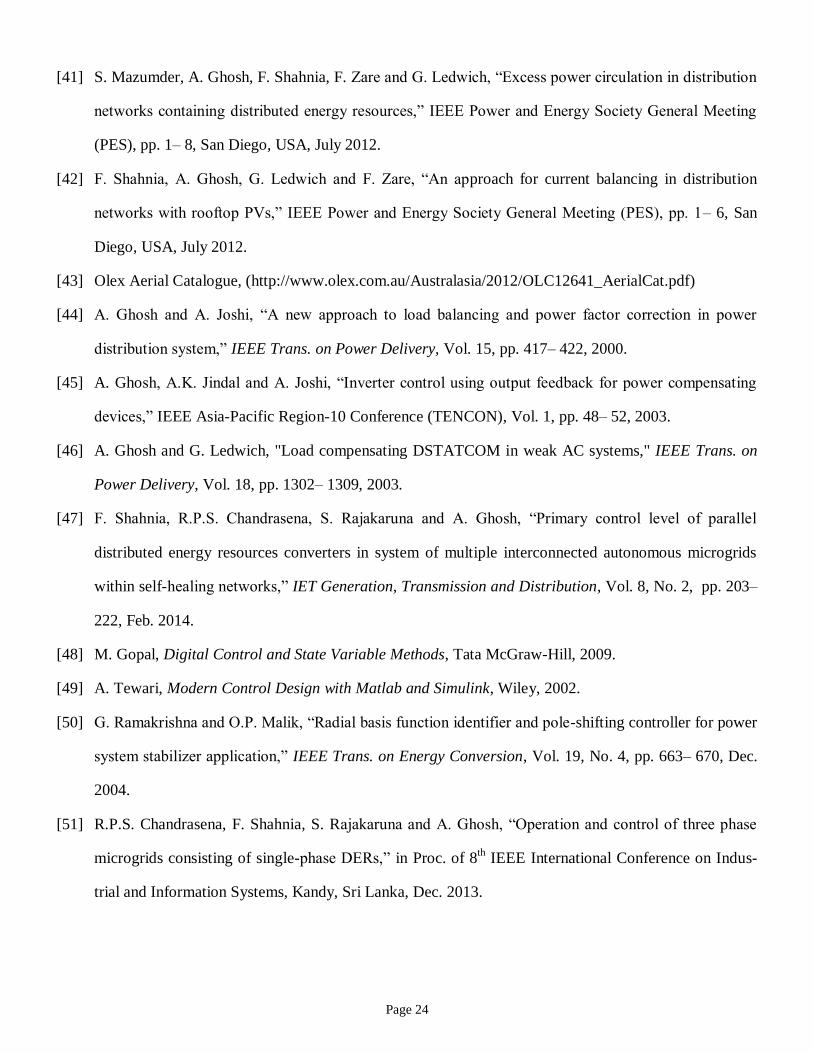
E. Case–5
Now, let us consider utilizing a DSTATCOM, with the topology shown in Fig. 1(b), in the MV network of
case-4, operating in voltage control strategy. In this configuration, the filter capacitor has an LV rating. Be-
fore DSTATCOM connection, the currents in DSTATCOM upstream are unbalanced (Fig. 8a-left). After the

Page 17
DSTATCOM connection, the actual and reference values of voltage across the filter capacitor are shown to-
gether in Fig. 8b-left and the tracking error is shown Fig. 8b-right. From this figure, it can be seen that the
tracking error of the controller is about 8 V peak to peak. However, the upstream current is not balanced (Fig.
8a-right), as discussed earlier in Section 3(B). Hence, for this configuration of DSTATCOM, voltage control
strategy fails.
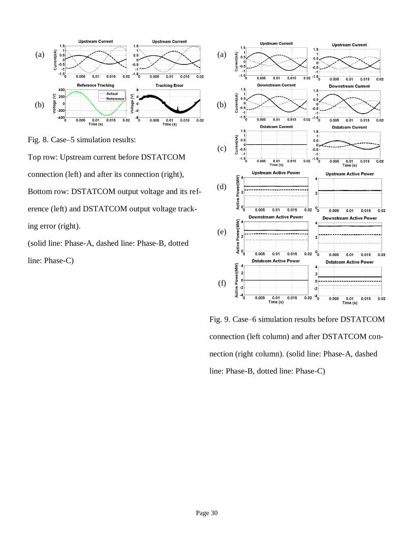
F. Case–6
Now, let us consider the network and DSTATCOM of case-5, where a current control strategy, as dis-
cussed in Section 3(B) is utilized instead of the voltage control strategy. The simulation results are shown in
Fig. 9.
As it can be seen from the results, before the DSTATCOM connection, the currents at the upstream and
downstream of the DSTATCOM are unbalanced (Fig. 9 a,b-left). The active power flow is 2.8, 2.3 and 1.5
MW respectively in phase-A, B and C (Fig. 9d-left). After the DSTATCOM connection, the upstream current
becomes balanced (Fig. 9a-left) and the active power becomes 2.3 MW in all phases (Fig. 9d-right). This is
achieved as the DSTATCOM absorbs 1.18 MW from phase-C and injects 1.16 MW to phase-A while it has
no power exchange with phase-B (Fig. 9f-right). In this case, the DSTATCOM has a loss of 20 kW, since it
is connected to an MV feeder.
5.3. Simulation Results Discussion
Based on the above simulation cases, it can be seen that for a DSTATCOM connected in LV feeder, a filter
type of LC with a voltage control strategy can properly circulate the reverse power flow and balance the up-
stream currents (as illustrated in Case-2). In the situations in which no reverse power flow is observed in any
of the phases, the DSTATCOM will only facilitate a set of balanced currents in its upstream (as illustrated in
Case-1). The DSTATCOM with a voltage control technique connected to the LV feeder, as proposed in this
paper, can facilitate off-grid operation mode for the system, providing that the DERs have adequate capabil-
ity to supply the local loads within the LV feeder (as illustrated in Case-3).
Similarly, it is realized that for a DSTATCOM connected in MV feeder, a filter type of LC with a voltage
control strategy can only be successful if the filter has MV rating (as illustrated in Case-4). To utilize a filter
with LV rating, the LCL filter with a voltage control strategy was shown to be unsuccessful in making the

Page 18
upstream currents balanced (as illustrated in Case-5). However, when a current control strategy is used in-
stead of the voltage control strategy, the DSTATCOM is successful for proper circulation of the reverse
power flow and balancing the upstream currents (as illustrated in Case-6). This is summarized in Table 1.
6. Conclusions
Large number of single- phase DERs, installed in one phase, can result in reverse power flow in that phase
if the generation capacity is higher than the phase load demand. In this paper, two different topologies are
discussed for power circulation through a DSTATCOM in order to prevent the reverse power flowing into
the upstream network. The proposed DSTATCOM is composed of a VSC with an LC filter, either connected
directly to the LV feeder or through a boosting transformer in case of the MV feeder. The simulation results
show that a voltage control strategy is effective for circulating the phase surplus power through the DSTAT-
COM in the LV network while it fails for MV applications due to the leakage inductance of the boosting
transformers. Hence a current control strategy is a preferred option for this case.
Appendix
A. Technical Parameters of the Network
The data of the network in Fig. 1 and 3 are listed in Table 2 and 3.
B. Control of LV Networks Operating in islanded mode
A LV feeder is considered with two DERs. Let us assume that each DER is supplied by a DC source and is
connected through an H-bridge VSC, an LC filter and an impedance of jLcoup to the LV feeder. The active
power (p) and reactive power (q) supplied by the DER to the LV feeder are then given by [47]
TTcfcf
T
T
Tcf
T
cfT
VVL
Vq
L
VVp
cos
sin
(A.1)
where VT and Vcf are respectively the LV feeder side and LC filter voltage of the coupling impedance and V =
| V | is the phasor representation of v(t).
In islanded mode, it is assumed that the frequency of the LV feeder reduces by , as the DER increases
its output active power from zero to its rated value. Hence, P- droop coefficient for the DER is

Page 19
ratedPm
(A.2)
Assuming to be constant for both of the DERs with different ratings, the ratio of P- droop coefficient
between the two DERs is
1,
2,
2
1
rated
rated
P
P
m
m
(A.3)
Similarly, it is assumed that the voltage of the LV feeder reduces by V, when the DER increases its output
reactive power from zero to its rated value. Hence, the Q-V droop coefficient for the DER is
ratedQ
Vn
(A.4)
Assuming V to be constant for both of the DERs with different ratings, the ratio of Q-V droop coefficient
between two DERs is
1,
2,
2
1
rated
rated
Q
Q
n
n
(A.5)
In [47], it was shown that the output active ratio and reactive power ratio among two DERs are the same as
the ratio of their rated active and reactive powers as
1
2
2
1
1
2
2
1 ,n
n
Q
Q
m
m
P
P
(A.6)
On the other hand, in parallel operation of converter-interfaced DERs in an islanded network, it is desired
that the voltage angle difference on two sides of the coupling inductance (i.e. cf – T) in (A.1) to be a small
value so that it is on the linear section of sinusoidal P- characteristic of (A.1). Similarly, it is desired that the
voltage drop across the coupling inductance (i.e. |Vcf | – |VT |) in (A.1) to be small (i.e. 1-2 %). For achieving
these assumptions, the coupling inductances are designed inversely proportional to the rated power of DERs
as [47]
1,
2,
1,
2,
2,
1,
rated
rated
rated
rated
coup
coup
Q
Q
P
P
L
L
(A.7)

Page 20
References
[1] L. Byrnes, C. Brown, J. Foster and L.D. Wagner, “Australian renewable energy policy: Barriers and
challenges,” Renewable Energy, Vol. 60, pp. 711– 721, Dec. 2013.
[2] M.A. Abdullah, A.P. Agalgaonkar and K.M. Muttaqi, “Climate change mitigation with integration of
renewable energy resources in the electricity grid of New South Wales, Australia,” Renewable Energy,
Vol. 66, pp. 305– 313, June 2014.
[3] A. Aslani and K.F.V. Wong, “Analysis of renewable energy development to power generation in the
United States,” Renewable Energy, Vol. 63, pp. 153– 161, March 2014.
[4] S. Spiecker and C. Weber, “The future of the European electricity system and the impact of fluctuating
renewable energy– A scenario analysis,” Energy Policy, Vol. 65, pp. 185– 197, Feb. 2014.
[5] R. Sen and S.C. Bhattacharyya, “Off-grid electricity generation with renewable energy technologies in
India: An application of HOMER,” Renewable Energy, Vol. 62, pp. 388– 398, Feb. 2014.
[6] Z. Ming, L. Ximei, L. Yulong and P. Lilin, “Review of renewable energy investment and financing in
China: Status, mode, issues and countermeasures,” Renewable and Sustainable Energy Reviews, Vol.
31, pp. 23– 37, March 2014.
[7] A. Zahedi, “Development of an economical model to determine an appropriate feed– in tariff for grid-
connected solar PV electricity in all states of Australia,” Renewable and Sustainable Energy Reviews,
Vol. 13, Issue 4, pp. 871– 878, May 2009.
[8] A. Bahadori and C. Nwaoha, “A review on solar energy utilisation in Australia,” Renewable and Sus-
tainable Energy Reviews, Vol. 18, pp. 1– 5, Feb. 2013.
[9] R.J. Davy and A. Troccoli, “Interannual variability of solar energy generation in Australia,” Solar En-
ergy, Vol. 86, Issue 12, pp. 3554– 3560, Dec. 2012.
[10] C.W. Hsu, “Using a system dynamics model to assess the effects of capital subsidies and feed-in tariffs
on solar PV installations,” Applied Energy, Vol. 100, pp. 205– 217, Dec. 2012.
[11] J.L. Silveira, C.E. Tuna and W. de Queiroz Lamas, “The need of subsidy for the implementation of
photovoltaic solar energy as supporting of decentralized electrical power generation in Brazil,” Renew-
able and Sustainable Energy Reviews, Vol. 20, pp. 133– 141, April 2013.
Page 21
[12] A. Macintosh and D. Wilkinson, “Searching for public benefits in solar subsidies: A case study on the
Australian government’s residential photovoltaic rebate program,” Energy Policy, Vol. 39, Issue 6, pp.
3199– 3209, June 2011.
[13] S. Srinivasan, “Subsidy policy and the enlargement of choice,” Renewable and Sustainable Energy Re-
views, Vol. 13, Issue 9, pp. 2728– 2733, Dec. 2009.
[14] S.B. Peterson and J.J. Michalek, “Cost-effectiveness of plug-in hybrid electric vehicle battery capacity
and charging infrastructure investment for reducing US gasoline consumption,” Energy Policy, Vol. 52,
pp. 429– 438, Jan. 2013.
[15] R.M. Krause, S.R. Carley, B.W. Lane and J.D. Graham, “Perception and reality: Public knowledge of
plug-in electric vehicles in 21 U.S. cities,” Energy Policy, Vol. 63, pp. 433– 440, Dec. 2013.
[16] F. Shahnia, A. Ghosh, G. Ledwich and F. Zare, “Predicting voltage unbalance impacts of plug-in elec-
tric vehicles penetration in residential low voltage distribution networks,” Electric Power Components
and Systems, Vol. 41, Issue 16, pp. 1594– 1616, Oct. 2013.
[17] B.K. Sovacool and R.F. Hirsh, “Beyond batteries: An examination of the benefits and barriers to plug-
in hybrid electric vehicles (PHEVs) and a vehicle-to-grid (V2G) transition,” Energy Policy, Vol. 37, Is-
sue 3, pp. 1095– 1103, March 2009.
[18] J.D.K. Bishop, C.J. Axon, D. Bonilla, et al. “Evaluating the impact of V2G services on the degradation
of batteries in PHEV and EV,” Applied Energy, Vol. 111, pp. 206– 218, Nov. 2013.
[19] K.C. Divya and J. Østergaard, “Battery energy storage technology for power systems– An overview,”
Electric Power Systems Research, Vol. 79, Issue 4, pp. 511– 520, April 2009.
[20] A. Purvins, I.T. Papaioannou and L. Debarberis, “Application of battery-based storage systems in
household demand smoothening in electricity distribution grids,” Energy Conversion and Management,
Vol. 65, pp. 272– 284, Jan. 2013.
[21] N.K.C. Nair and N. Garimella, “Battery energy storage systems: Assessment for small-scale renewable
energy integration,” Energy and Buildings, Vol. 42, Issue 11, pp. 2124– 2130, Nov. 2010.
Page 22
[22] D. Parra, G.S. Walker and M. Gillott, “Modeling of PV generation, battery and hydrogen storage to
investigate the benefits of energy storage for single dwelling,” Sustainable Cities and Society, Vol. 10,
pp. 1– 10, Feb. 2014.
[23] J.A. Peças Lopes, N. Hatziargyriou, J. Mutale, et al. “Integrating distributed generation into electric
power systems: A review of drivers, challenges and opportunities,” Electric Power Systems Research,
Vol. 77, Issue 9, pp. 1189– 1203, July 2007.
[24] W El-Khattam and M.M.A Salama, “Distributed generation technologies, definitions and benefits,”
Electric Power Systems Research, Vol. 71, Issue 2, pp. 119– 128, Oct. 2004.
[25] J.C. Hernández, F.J.R. Rodriguez and F. Jurado, “Technical impact of photovoltaic distributed genera-
tion on radial distribution systems: Stochastic simulations for a feeder in Spain,” International Journal
of Electrical Power & Energy Systems, Vol. 50, pp. 25– 32, Sept. 2013.
[26] R.A. Walling, R. Saint, R.C. Dugan, J. Burke and L.A. Kojovic, “Summary of distributed resources
impact on power delivery systems,” IEEE Trans. on Power Delivery, Vol. 23, pp. 1636– 1644, 2008.
[27] F. Shahnia, R. Majumder, A. Ghosh, G. Ledwich and F. Zare, “Voltage imbalance analysis in residen-
tial low voltage distribution networks with rooftop PVs,” Electric Power Systems Research, Vol. 81,
pp. 1805– 1814, 2011.
[28] F. Shahnia and A. Ghosh, “Decentralized voltage support in a low voltage feeder by droop based volt-
age controls PVs,” in Proc. of 23rd
Australasian Universities Power Engineering Conference (AUPEC),
Sept. 2013, Hobart, Australia.
[29] M. Hamzeh, H. Karimi and H. Mokhtari, “A new control strategy for a multi-bus MV microgrid under
unbalanced conditions,” IEEE Trans. on Power System, Vol. 27, No. 4, pp. 2225– 2232, Nov. 2012.
[30] A. Ghosh and G. Ledwich, Power Quality Enhancement using Custom Power Devices. Boston; Kluwer
Academic, 2002.
[31] F. Shahnia, A. Ghosh, G. Ledwich and F. Zare, “Voltage unbalance improvement in low voltage
residential feeders with rooftop PVs using custom power devices,” International Journal of Electrical
Power & Energy Systems, Vol. 55, pp. 362– 377, Feb. 2014.

Page 23
[32] B. Han, B. Bae, S. Baek and G. Jang, “New configuration of UPQC for medium-voltage application,”
IEEE Trans. on Power Delivery, Vol. 21, No. 3, pp. 1438– 1444, July 2006.
[33] Y. Li, D.M. Vilathgamuwa and P.C. Loh, “Microgrid power quality enhancement using a three-phase
four-wire grid-interfacing compensator,” IEEE Trans. on Industrial Applications, Vol. 41, No. 6, pp.
1707– 1719, Nov./Dec. 2005.
[34] J. Guerrero, M. Chandorkar, T. Lee and P. Loh, “Advanced control architectures for intelligent
microgrids-Part II: Power quality, energy storage, and AC/DC microgrids,”, IEEE Trans. on Industrial
Electronics, Vol. 60, No. 4, pp. 1263– 1270, April 2013.
[35] M. Brenna, R. Faranda and E. Tironi, “A new proposal for power quality and custom power
improvement: Open UPQC,” IEEE Trans. on Power Delivery, Vol. 24, No. 4, pp. 2107– 2116, Oct.
2009.
[36] H.M. Wijekoon, D.M. Vilathgamuwa and S.S. Choi, “Interline dynamic voltage restorer: an
economical way to improve interline power quality,” IEE Proc. Generation, Transmission and
Distribution, Vol. 150, No. 5, pp. 513– 520, Sept. 2003.
[37] A.K. Jindal, A. Ghosh and A. Joshi, “Interline unified power quality conditioner,” IEEE Trans. on
Power Delivery, Vol. 22, No. 1, pp. 364– 372, 2007.
[38] T. Zaveri, B. Bhalja and N. Zaveri, “Comparison of control strategies for DSTATCOM in three-phase,
four-wire distribution system for power quality improvement under various source voltage and load
conditions,” International Journal of Electrical Power & Energy Systems, Vol. 43, Issue 1, pp. 582–
594, Dec. 2012.
[39] B. Singh, P. Jayaprakash and D.P. Kothari, “New control approach for capacitor supported
DSTATCOM in three-phase four wire distribution system under non-ideal supply voltage conditions
based on synchronous reference frame theory,” International Journal of Electrical Power & Energy
Systems, Vol. 33, Issue 5, pp. 1109– 1117, June 2011.
[40] D. Sreenivasarao, P. Agarwal and B. Das, “A T-connected transformer based hybrid DSTATCOM for
three-phase, four-wire systems,” International Journal of Electrical Power & Energy Systems, Vol. 44,
Issue 1, pp. 964– 970, Jan. 2013.
Page 24
[41] S. Mazumder, A. Ghosh, F. Shahnia, F. Zare and G. Ledwich, “Excess power circulation in distribution
networks containing distributed energy resources,” IEEE Power and Energy Society General Meeting
(PES), pp. 1– 8, San Diego, USA, July 2012.
[42] F. Shahnia, A. Ghosh, G. Ledwich and F. Zare, “An approach for current balancing in distribution
networks with rooftop PVs,” IEEE Power and Energy Society General Meeting (PES), pp. 1– 6, San
Diego, USA, July 2012.
[43] Olex Aerial Catalogue, (http://www.olex.com.au/Australasia/2012/OLC12641_AerialCat.pdf)
[44] A. Ghosh and A. Joshi, “A new approach to load balancing and power factor correction in power
distribution system,” IEEE Trans. on Power Delivery, Vol. 15, pp. 417– 422, 2000.
[45] A. Ghosh, A.K. Jindal and A. Joshi, “Inverter control using output feedback for power compensating
devices,” IEEE Asia-Pacific Region-10 Conference (TENCON), Vol. 1, pp. 48– 52, 2003.
[46] A. Ghosh and G. Ledwich, "Load compensating DSTATCOM in weak AC systems," IEEE Trans. on
Power Delivery, Vol. 18, pp. 1302– 1309, 2003.
[47] F. Shahnia, R.P.S. Chandrasena, S. Rajakaruna and A. Ghosh, “Primary control level of parallel
distributed energy resources converters in system of multiple interconnected autonomous microgrids
within self-healing networks,” IET Generation, Transmission and Distribution, Vol. 8, No. 2, pp. 203–
222, Feb. 2014.
[48] M. Gopal, Digital Control and State Variable Methods, Tata McGraw-Hill, 2009.
[49] A. Tewari, Modern Control Design with Matlab and Simulink, Wiley, 2002.
[50] G. Ramakrishna and O.P. Malik, “Radial basis function identifier and pole-shifting controller for power
system stabilizer application,” IEEE Trans. on Energy Conversion, Vol. 19, No. 4, pp. 663– 670, Dec.
2004.
[51] R.P.S. Chandrasena, F. Shahnia, S. Rajakaruna and A. Ghosh, “Operation and control of three phase
microgrids consisting of single-phase DERs,” in Proc. of 8th IEEE International Conference on Indus-
trial and Information Systems, Kandy, Sri Lanka, Dec. 2013.

Page 25
Table 1. Summary of the simulation results.
Simulation
Case No.
DSTATCOM
Connection
DSTATCOM
Filter Type
Control
Strategy
Summary Result
1 LV LC
(LV rating)
Voltage The LV network contains
unbalanced loads.
Proper power circulation through the DSTATCOM
Balanced currents in the DSTATCOM upstream
2 LV LC
(LV rating)
Voltage The LV network contains
unbalanced loads and unbal-
anced single-phase DERS.
Proper power circulation through the DSTATCOM
Balanced currents in the DSTATCOM upstream
3 LV LC
(LV rating)
Voltage The grid in this case is iso-
lated. DERs are only availa-
ble in phase-A and C while
unbalanced loads are dis-
tributed in all phases.
Proper power circulation through the DSTATCOM
DERs in phase-A and C supply the load in phase-B
through DSTATCOM.
4 MV LC
(MV rating)
Voltage The MV network experienc-
es unbalanced loads and un-
balanced generations.
Proper power circulation through the DSTATCOM
Balanced currents in the DSTATCOM upstream
5 MV LCL
(LV rating)
Voltage Same Network as Case–4 Unbalanced currents in the DSTATCOM upstream
6 MV LCL
(LV rating)
Current Same Network as Case–4 Proper power circulation through the DSTATCOM
Balanced currents in the DSTATCOM upstream

Page 26
Table 2. Technical data of the network in simulation cases 1 to 3.
MV Feeder 11 kV L–L, 50 Hz, R = 0.5 , X =1.57
Distribution Transformer 100 kVA, 11 kV/ 410 V, 50 Hz, ZI = 10%
LV Feeder 410 V L–L, 50 Hz, R = 0.022 , X =0.022
Three-phase LV load SA = 19.5 + j 6.3, SB = 38.6 + j 13, SC = 53 + j 19.2 kVA
DER for Case– 2 one single– phase DER with P = 40 kW, PF = 1, connected to phase–A
DERs for Case– 3 2 single phase DERs with Prated = 50 kW, Srated = 60 kVA with Lcoupling = 450 H
(connected to phase– A) and Lcoupling = 680 H (connected to phase–C)
DSTATCOM Rf = 0.1 , Lf =4 mH, Cf =25 F, Vdc=1 kV, a =1, h = 10– 4
K =[1.5463 –0.7092]
Table 3. Technical data of the network in simulation cases 4 to 6.
HV Feeder 132 kV L–L, 50 Hz, R = 0.25 , X =3.14
Transformer 15 MVA, 132 / 11 kV, 50 Hz, ZI = 5%
MV Feeder 11 kV L–L, 50 Hz, R = 0.5 , X =1.57
Three-phase MV load SA = 2 + j 0.66, SB = 4 + j 1.33, SC = 6+ j 2 MVA
DER for Case–6 one single– phase DER with P = 0.45 MW, PF = 1, connected to phase–A
DSTATCOM for case–4 Rf = 0.1 , Lf =4 mH, Cf =25 F, Vdc=13 kV, a =1, h = 10– 4
K =[1.5463 –0.7092]
DSTATCOM for case–5
and 6
Rf = 0.1 , Lf =4 mH, Cf =25 F, Vdc=1 kV, a =11, h = 10– 4
21
21
1
1
025.01237.01
7269.414746.858019.43
zz
zz
zR
zS

Page 27
Vdc
Lf
(a)
if
+
vcf
iT
S1
S1
S2
S2
1:a
Vdc
Cf
Rf
Lf
+
(b)
if
+
vcf
S1
S1
S2
S2
Cf
Rf
+
iT
1:a
vTvT
Fig. 1. DSTATCOM toplogy with power circulation capability to be installed in:
(a) LV feeders, (b) MV feeders.
cfvky )(
+hh
Hysteresis Control
+1
1
+
)()(
)()()()1( 21
kCxky
kiGkuGkFxkx Tc
u
VSC and Filter System
LQR Gain
kuc kyref
1
1
1
zF
zG
ku
ky
c
1k
+
LQR Gain
2k
High Pass Filter
s
s+0
~, reffi
fi~
fi(a)
h
Hysteresis Control
+1
1
+
1zS
1zR )()(
)()()()1( 21
kCxky
kvGkuGkFxkx Tc
u
VSC and Filter System
Pole Shift Control
kuc kyref
1
1
1
zF
zG
ku
ky
c
Tiky )(
(b)
+h
ZF
132/11 kV
Transformer
ZF
vT
11 kV/410 V
Transformer
iT
Single-phase
Loads and DERs
upstream downstream
(b)
CB
ZF
132/11 kV
Transformer
vT
11 kV/410 V
Transformer
iT
Single-phase
Loads and DERs
upstream
downstream
(a)
CB
Zf
LV
DSTATCOM
and Filter
MV
DSTATCOM
and Filter
Fig. 2. Closed-loop switching control block diagram for:
(a) voltage control strategy based on LQR,
(b) current control strategy based on pole-shift.
Fig. 3. Schematic diagram of a distribution
network with DSTATCOM installed in:
(a) LV feeder and (b) MV feeder.

Page 28
(a)
(a)
(b) (b)
(c) (c)
(d)
(d)
(e) (e)
(f) (f)
Fig. 4. Case–1 simulation results before DSTAT-
COM connection (left column) and after DSTAT-
COM connection (right column). (solid line: Phase-
A, dashed line: Phase-B, dotted line: Phase-C)
Fig. 5. Case–2 simulation results before DSTATCOM
connection (left column) and after DSTATCOM con-
nection (right column). (solid line: Phase-A, dashed
line: Phase-B, dotted line: Phase-C)

Page 29
(a)
(a)
(b) (b)
(c) (c)
(d)
(d)
(e) (e)
(f) (f)
Fig. 6. Case–3 simulation results in grid-connected
mode (left column) and off-grid mode (right column)
operation of the LV feeder while the DSTATCOM is
connected to the LV feeder in both modes. (solid
line: Phase-A, dashed line: Phase-B, dotted line:
Phase-C)
Fig. 7. Case–4 simulation results before DSTATCOM
connection (left column) and after DSTATCOM con-
nection (right column). (solid line: Phase-A, dashed
line: Phase-B, dotted line: Phase-C)
Page 30
(a)
(a)
(b) (b)
Fig. 8. Case–5 simulation results:
Top row: Upstream current before DSTATCOM
connection (left) and after its connection (right),
Bottom row: DSTATCOM output voltage and its ref-
erence (left) and DSTATCOM output voltage track-
ing error (right).
(solid line: Phase-A, dashed line: Phase-B, dotted
line: Phase-C)
(c)
(d)
(e)
(f)
Fig. 9. Case–6 simulation results before DSTATCOM
connection (left column) and after DSTATCOM con-
nection (right column). (solid line: Phase-A, dashed
line: Phase-B, dotted line: Phase-C)
Related Documents

![Synthesis and performance optimisation of spray coated ...eprints.nottingham.ac.uk/59127/1/Synthesis-已融合.pdf · 41 cilitated [1], as metal xanthates allow for the straightforward](https://static.cupdf.com/doc/110x72/5e3b1303073ed1502f0ee7db/synthesis-and-performance-optimisation-of-spray-coated-epdf-41-cilitated.jpg)


