NASA Technic a! Memorandum 102578 Multiwavelength Pyrometry to Correct for Reflected Radiation ..... Daniel L.P. Ng Lewis Research Center_ Cleveland, Ohio June 1990 T_ CORRFCT FOP, PEFLFCTE_ PANIa, TION ("._A_A) ... 1_ p CSCL 14 Q NgO--Z_'I.4 unclas 028Q144 https://ntrs.nasa.gov/search.jsp?R=19900014398 2018-07-13T02:30:11+00:00Z

Welcome message from author
This document is posted to help you gain knowledge. Please leave a comment to let me know what you think about it! Share it to your friends and learn new things together.
Transcript
NASA Technic a! Memorandum 102578
Multiwavelength Pyrometry to Correctfor Reflected Radiation .....
Daniel L.P. Ng
Lewis Research Center_
Cleveland, Ohio
June 1990
T_ CORRFCT FOP, PEFLFCTE_ PANIa, TION ("._A_A)
... 1_ p CSCL 14 Q
NgO--Z_'I.4
unclas
028Q144
https://ntrs.nasa.gov/search.jsp?R=19900014398 2018-07-13T02:30:11+00:00Z
CY_0
t.f)!
I,.I
MULTIWAVELENGTH PYROMETRYTO CORRECT FOR REFLECTED RADIATION
Daniel L.P. NgNational Aeronautics and Space Administration
Lewis Research CenterCleveland, Ohio 44135
SUMMARY
Computer curve fitting isused-in-multiwavelength pyrometry to measurethe temperature of a surface in the presence of reflected radiation by decom-
posing its radiation spectrum. Computer-simulated spectra (at a surface tem-perature of 1000 K; in the wavelength region 0.3 to 20 pm; with a reflectedradiation-source temperature of 700 to 2500 K and reflector emissivity from0.1 to 0.9) were generated and decomposed. This method of pyrometry determinedthe surface temperatures under these conditions to within 5 percent. The prac-ticability of the method was further demonstrated by the successful analysis ofa related problem - decomposition of the real spectrum of an infrared source
containing two emitters to determine their temperatures.
INTRODUCTION
In pyrometry, the temperature of a surface is determined by measuring theemitted radiation. The emitted radiation obeys Planck's blackbody distributionlaw. In conventional pyrometers (the so-called single-color pyrometers), theradiation is measured in a narrow wavelength band, usually in the visible ornear-infrared bands (in the region of 0.5 to 1.0 lam). This method of temper-ature measurement requires some knowledge of the surface emissivity. Two-colorpyrometers measure the emitted radiation in two wavelength bands, and by assum-ing that the ratio of emissivities in the two bands is known, the surface tem-perature is determined without knowing its emissivity. In general, as long asthe emissivity does not change rapidly with wavelength, accurate temperaturemeasurements are obtained. However, both methods are susceptible to errorscaused by reflected radiation. Reflected radiation originates from sourcesother than the surface under consideration and reaches the detector throughreflection from the surface. Ceramics are materials from which future advanced
propulsion systems will be built. This class of material typically has lowemissivity (0.15 to 0.8); hence, there is high reflectivity in the wavelengthband where conventional pyrometers operate (ref. 1). Consequently, a potentialfor large error exists when pyrometry is employed to measure the temperature ofceramics. To correct for the reflected radiation, we propose the use of multi-wav¢Tength pyrometry that measures temperature by curve fitting the measuredradiation spectrum. This method has been used to simultaneously measure tem-perature and spectral emissivity with accuracy up to 1 percent (refs. 2 to 4)and to measure temperature distribution with a known spectral emissivity(ref. 5).
REFLECTED RADIATION
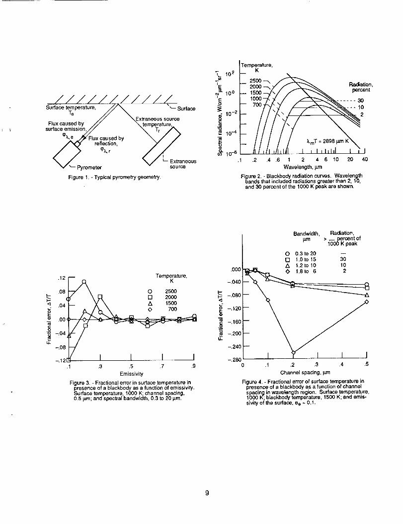
Figure 1 shows a pyrometry arrangement in which both the emitted andreflected radiations reach the detector. One can see that, in addition to the

radiation (signal) originating from the measuredsurface at temperature Te,there is an undesirable componentoriginating from an extraneous source at tem-perature Tr. The arrangement shows that the radiant flux detected by a pyrom-eter can be represented mathematically as
_7, = _),,e + _),,r (1)
where _X is the detected flux decomposed into two components: _X,e, caused
by emission from the surface under consideration and _X,r, caused by reflec-tion from the extraneous source. As a result, depending on the magnitude ofthis flux, the final temperature measurement contains unavoidable errors.Neither the one-color nor the two-color pyrometry is capable of accounting forand, hence, eliminating this source of error.
By application of Kirchoff's law, and the PIanck distribution of blackbodyradiation Lx(T ), the two components are expressed as
_X,e _ aee(X)LX(Te) (2)
whereCX,r = abae(X)er(X)Lx(Tr)
Cl 1
L_(T) = _ exp(c2/XT) _ I
(3)
In equations (2) and (3), the quantity a is a geometric constant of the py-rometer, and b is a geometric constant of the experimental setup containingquantities such as the view factors (solid angle). The radiation constantsc 1 and c2 are given by
c 1 = 2c2h (4)
c 2 = ch/k (5)
where c = 3x10⁸ m/sec is the velocity of light, h _ 6.6x10 -34 l-sec is thePlanck constant, k = 1.38x10 -23 J/K is the Boltzmann constant, and ee(X ), isthe emissivity of the surface, which is generally a function of wavelength and
may also be temperature dependent. The quantity er(k) is the emissivity ofthe extraneous source, and for a blackbody, er(X ) = 1. The quantity ae(X ) isthe reflectance of the target surface and is equal to (1 - ee(X)), if it has nospecular component. Multiple reflection between the two surfaces is neglected.Curves of the Planck radiation distribution for a blackbody are shown in fig-
ure 2 as a function of wavelength for different temperatures. A temperature Tcan be calculated from the relative spectral distribution near the peak becausethe wavelength at the peak varies inversely with T (Wien's displacement law).It is thus possible to find the two temperatures Te and T r in figure 1because of their different spectral distributions.
PYROMETRY METHODS
One- and Two-Color Pyrometry and Polaradiometry
Temperature measurement by pyrometry is based on detecting and analyzingthe radiation of equation (1). In both one- and two-color pyrometry, the
2
reflected radiation is ignored or considered small compared to the emittedradiation. This is not a bad approximation for two-color pyrometry, if theextraneous radiation sources have temperatures not much different from the
target surface.
In the single-color pyrometer, the radiation emitted in a narrow wave-length band aX centered at _1 is detected by a suitable detector system.The detected flux _ is equal to the integral obtained by integrating equa-
tion (2) over this wavelength region:
.Xl+_k/2[
_(_1) = aJ ee(_)Ux(Te)dX
XI-_X/2
(6)
When a_ is small, it can be assumed that the integrand in equation (6) is
constant and that the integral is approximated by aX. Then the detector
signal is
Cl 1
s I = kla_ee(_l) _-g exp(c2/klTe) - 1(7)
where k I is the detector sensitivity factor. By knowing the emissivity of thebody, we can determine its temperature from the detector signal.
If a second narrow wavelength band 6k centered around k 2 is selected,
the detected signal s2 is
Cl 1
s 2 = k2aAkee(k2) _ exp(c2/k2Te) - 1)'2
(8)
The ratio of equations (7) and (8) contains the ratio of the emissivities,which is unity if they are the same. This is the two-color pyrometry method.Neither method addresses the issue of reflected radiation. If it is not negli-
gible, the resulting error can be substantial.
Murray (ref. 6) demonstrated an ingenious method for obtaining the temper-ature of a surface by explicitly employing the reflected radiation from a knownexternal source. By carefully analyzing the emitted and reflected radiations,
explicitly taking into consideration their polarizations (polarization paralleland perpendicular to the incident plane), and applying Kirchoff's law in anarrow band around _, Murray obtained an expression for the signal I caused
by the combined radiation.
In his expression, ep and e s are the sample emittances for radiation
polarized parallel and perpendicular to the plane of incidence; E is the
(9)
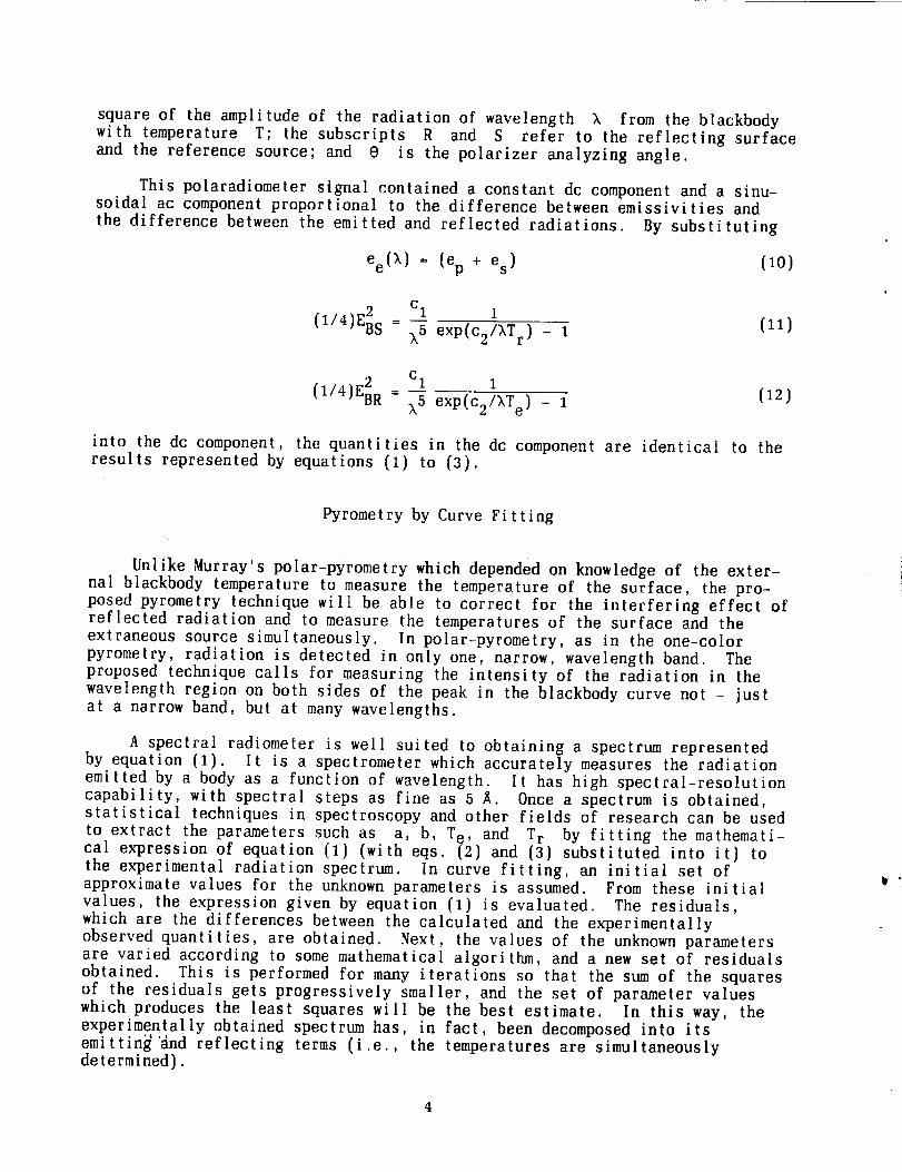
square of the amplitude of the radiation of wavelength k from the blackbodywith temperature T; the subscripts R and S refer to the reflecting surfaceand the reference source; and 0 is the polarizer analyzing angle.
This polaradiometer signal contained a constant dc component and a sinu-soidal ac component proportional to the difference between emissivities and
the difference between the emitted and reflected radiations. By substituting
ee(X) = (ep + es) (10)
2 Cl 1
(I/4)EBs - k5 exp(c2/kTr) - I(ll)
Cl 1 (12)(1/4)EBR _ 7 exp(c27kTe) - 1
into the dc component, the quantities in the dc component are identical to theresults represented by equations (1) to (3).
Pyrometry by Curve Fitting
Unlike Murray's _ polar'pyrometry which depended on knowledge of the exter-nal blackbody temperature to measure the temperature of the surface, the pro-posed pyrometry technique will be able to correct for the interfering effec[ ofreflected radiation and to measure the temperatures of the surface and theextraneous source simultaneously. In polar-pyrometry, as in the one-colorpyrometry, radiation is detected in only one, narrow, wavelength band. Theproposed technique calls for measuring the intensity of the radiation in thewavelength region on both sides of the peak in the blackbody curve not - justat a narrow band, but at many wavelengths.
A spectral radiometer is well suited to obtaining a spectrum representedby equation (1). It is a spectrometer which accurately measures the radiationemitted by a body as a function of wavelength. It has high spectral-resolutioncapability, with spectral steps as fine as 5 _. Once a spectrum is obtained,statistical techniques in spectroscopy and other fields of research can be used
to extract the parameters such as a, b, T e, and T r by fitting the mathemati-cal expression of equation (1) (with eqs. (2) and (3} substituted into it) to
the experimental radiation spectrum. In curve fitting, an initial set ofapproximate values for the unknown parameters is assumed. From these initialvalues, the expression given by equation (1) is evaluated. The residuals,which are the differences between the calculated and the experimentallyobserved quantities, are obtained. Next, the values of the unknown parametersare varied according to some mathematical algorithm, and a new set of residualsobtained. This is performed for many iterations so that the sum of the squaresof the residuals gets progressively smaller, and the set of parameter valueswhich produces the least squares will be the best estimate. In this way, theexperimentally obtained spectrum has, in fact, been decomposed into itsemitting'and reflecting terms (i.e., the temperatures are simultaneouslydetermined).
4
CO]_fl:_UTEREXPERIMENTATION
Simulated composite spectra were generated mathematically according to
equations (1) to (3). These spectra consisted of radiation from a surfacewith emissivity ee(_) = constant and temperature T e, and reflected radiationfrom a blackbody with emissivity er(X ) = 1 and temperature T r. The chosentemperature T e was 1000 K and T r values were 700, 1500, 2000, and 2500 K.
Only three significant figures were retained by this calculation. This numeri-cal roundoff is equivalent to the introduction of some error into the data.
The wavelength region of the simulated spectrum is from 0.3 to 20 pm repre-sented by 37 equally spaced channels. Values of e e vary from 0.1 to 0.9.
The temperatures of the two surfaces and the emissivity e e were deter-mined from the spectra. These were decomposed on a personal computer byrunning a commercial, scientific, statistics package (with least-squares,curve-fitting capabilities) called RSI. Other similar computer software couldalso have been used.
Curve fitting decomposes a spectrum into its constituent Planck functionsby simultaneous extraction of the two temperatures. The computer program alsoyields the standard errors of these quantities resulting from the statistics offitting the data to the functional relationship assumed by equations (1) to(3). The reported significance level is 0.0001. In the present computerexperimentation, we define the error as the deviation of the fitted temperaturefrom 1000 K. These errors are of the same order-of-magnitude as those esti-mated statistically by the computer program. The variation of these errorswith temperature and emissivity is shown in figure 3. It shows that as theemissivity decreases, the fractional error of the result increases rapidly.The results indicate that for emissivity larger than 0.3, there is sufficient
accuracy in the temperature so determined.
By increasing the number of channels in the wavelength region representedby the spectrum, the fractional error can be reduced. The case of T e = 1000 K,
T r = 1500 K, e e = 0.1, and bandwidth 0.3 to 20 um is shown in figure 4. Whenthe number of channels is increased from 37 to 193, 394, 462 and 924 (corre-
sponding to channel spacing of 0.5, 0.2, 0.1, 0.05, and 0.02 pm), the frac-tional error decreases from 0.05 to less than 0.01. However, this increase in
accuracy is accompanied by a corresponding increase in computation time.
The fractional error increases when the spectral bandwidth describing thespectrum is reduced. In addition to the 0.3- to 20-_m wavelength region, the
following wavelength regions were also investigated (fig. 2): (1) 1.8 to 6 _m(corresponding to detecting radiation greater than 30 percent of the 1000 Kpeak), (2) 1.2 to 10 wm (corresponding to detecting radiation greater than10 percent of the 1000 K radiation peak), and (3) 1.0 to 15 pm (correspondingto detecting radiation greater than 2 percent of the 1000 K peak). The resultsin figure 4 show that the bandwidth should be at least 1.2 to 10 pm (a wave-length ratio of 8).
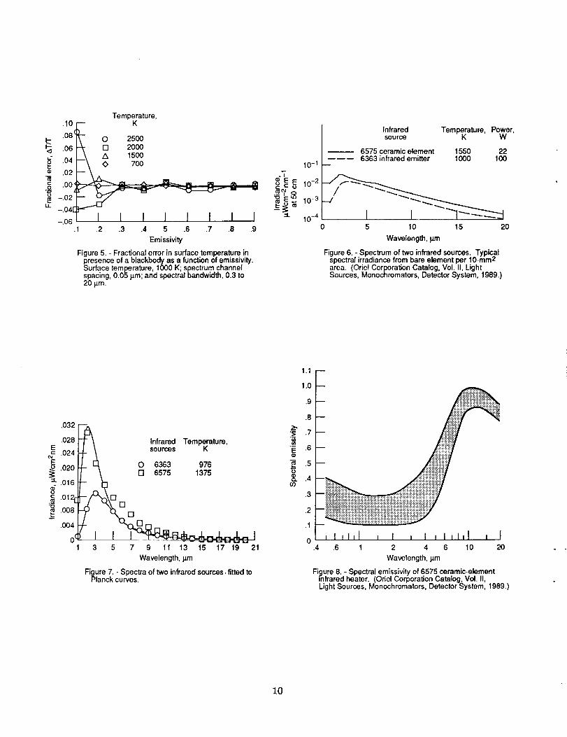
A channel spacing of 0.05 pm seems to be an optimal value. The fractionalerror for various extraneous source temperatures, as a function of emissivity
with this channel spacing, is shown in figure 5. It can be seen that exceptfor an extraneous source temperature of 2500 K and surface emissivity 0.1, thefractional error for all the other situations is less than 0.04. The results
indicate that for this optimized channel spacing of 0.05 pm, there is suffi-
cient accuracy in the temperature determined when the emissivity is larger than0.2, compared to the necessary value of emissivity larger than 0.3 mentionedpreviously when the channel spacing was 0.5 pm.
It is informative to compare the flux _e from the surface to the flux_r from the reflected extraneous source. Integration of equations (2) and (3)over the range of 0.3 to 20 _m is approximated by integration from zero toinfinity. The resultant flux follows the T4 Stefan-Boltzmann law. The fluxratio _e/_r is given by
(13)
For the case ee(X) = 0.1, e r = 1, a e _ 1 - ee(X ), T e = 1000 K, T r : 1500 K,and b - 1 (b is given by the ratio of the solid angle subtended by the 1500 Kbody and 2_), this flux ratio is 0.022. Thus the temperature can be deter-mined in the presence of high levels of reflecting flux.
INSTRUMENTATION
A spectral radiometer is used to obtain a complete spectrum of the bodywhose temperature we want to measure. Several commercial units exist that
operate from about 0.3 wm to as far as 20 _m. These instruments are completelyautomated by microprocessor control. The resultant spectrum is in digitizednumerical form and can be easily transferred to a computer system such as theIBM, IBM PC, and the VAX for processing and analysis.
It may take about 30 sec to accumulate a spectrum, but for developmentpurposes, this is quite adequate. The collected spectrum is then analyzed bya statistical program. However, in many applications, the 30-sec data-acquisition time may be too slow. In that situation, an optical multichannelanalyzer, which accumulates the whole spectrum instantly, can be used.
Presently, most optical multichannel analyzers use array silicon detec-tors, which are sensitive from about 0.2 to 1 _m. The spectra of transientevents are routinely collected by workers in spectroscopy. For pyrometry pur-poses, in order to detect the whole spectrum, operation up to at least 2.5 pJnis required. Fortunately, newer detectors, such as InGaAs and PtSi, arebecoming available in array packages. Thus, the data acquisition can beinstantly accomplished.
The temperature extraction is accomplished by computer software. In thepreliminary results documented here, the data transfer and interfacing betweenthe computer programs are performed manually. In a fully developed system, anew-generation, high-speed, personal computer will be incorporated into thedata acquisition with optimized software. Temperature output in a matter ofseconds is no doubt possible.
6
SOME EXAMPLES
The multiwavelength pyrometry technique discussed in the "PyrometryMethods" section was applied to analyze the real spectrum of two radiators.The problem is mathematically identical to the simulation described in the
"Computer Experimentation" section.
There are two, commercial, Oriel, infrared sources that have data sheets
providing the spectral irradiance from 1 to 20 pm (Oriel Corporation Catalog,Vol. II, Light Sources, Monochromators, Detector Systems, 1989.}: the 22-W,1550 K, 6575 ceramic element and the lO0-W, 1000 K, 6363 infrared emitter.The data sheets provide enough information to determine temperatures of these
sources {fig. 6). The data for these infrared sources were fitted to the sin-gle Planck curve (eq. (2)) and constant emissivity was assumed to obtain tem-peratures.of 976 K (within 2.5 percent error) for the 6363 ceramic element and1375 K for the 6575 infrared emitter (with an unacceptable error of almost
12 percent). Figure 7 shows the fitted curves and data for the two infrared
sources.
The agreement for the 6363 source was very good; whereas, the agreementfor the 6575 was certainly unacceptable. An examination of the graph in thedata sheet revealed some structures in the spectrum between 3 and 6 om; the
cause was suspected to be the variability in the 6575 emissivity with wave-length. Indeed, the manufacturer has provided, in the form of a broadbandcurve, the emissivity of the 6575 ceramic element as a function of wavelength
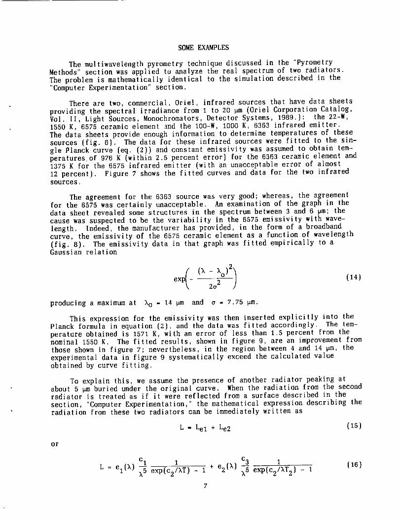
(fig. 8). The emissivity data in that graph was fitted empirically to aGaussian relation
2
exp - - - (14)2e 2
producing a maximum at k o = 14 _m and a = 7.75 pm.
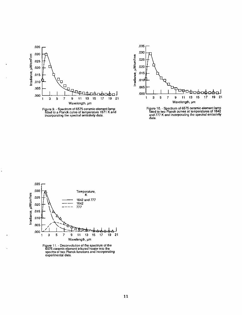
This expression for the emissivity was then inserted explicitly into thePlanck formula in equation (2), and the data was fitted accordingly. The tem-perature obtained is 1571 K, with an error of less than 1.5 percent from thenominal 1550 K. The fitted results, shown in figure 9, are an improvement from
those shown in figure 7; nevertheless, in the region between 4 and 14 pm, theexperimental data in figure 9 systematically exceed the calculated valueobtained by curve fitting.
To explain this, we assume the presence of another radiator peaking atabout 5 _m buried under the original curve. When the radiation from the secondradiator is treated as if it were reflected from a surface described in the
section, "Computer Experimentation," the mathematical expression describing theradiation from these two radiators can be immediately written as
L = Lel + Le2 (15)
or
Cl 1
L = el(),) _ exp(c2/kT) _ 1
c3 1
+ e2(k) _ exp(c2/kT2) -(16)
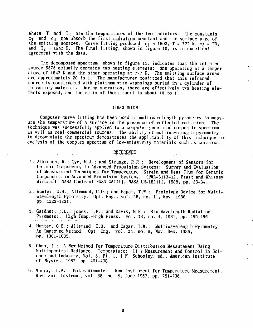
where T and T2 are the temperatures of the two radiators, The constantsc I and c 3 now absorb the first radiation constant and the surface area of
the emitting sources. Curve fitting produced c I = 1602, T = 777 K, c 3 = 70,and T 2 = 1642 K. The final fitting, shown in figure 10, is in excellentagreement with the data.
The decomposed spectrum, shown in figure 11, indicates that the infraredsource 6575 actually contains two heating elements: one operating at a temper-ature of 1642 K and the other operating at 777 K. The emitting surface areasare approximately 20 to 1. The manufacturer confirmed that this infraredsource is constructed with platinum wire wrappings buried in a cylinder of
refractory material. During operation, there are effectively two heating ele-ments exposed, and the ratio of their radii is about 10 to 1.
CONCLUSION
Computer curve fitting has been used in multiwavelength pyrometry to meas-ure the temperature of a surface in the presence of reflected radiation. Thetechnique was successfully applied to a computer-generated composite spectrumas well as real commercial sources. The ability of multiwavelength pyrometryto deconvolute the spectrum demonstrates the applicability of this technique toanalysis of the complex spectrum of low-emissivity materials such as ceramics.
REFERENCE
1. Atkinson, W.; Cyr, M.A.; and Strange, R.R.: Development of Sensors forCeramic Components in Advanced Propulsion Systems: Survey and Evaluationof Measurement Techniques for Temperature, Strain and Heat Flux for CeramicComponents in Advanced Propulsion Systems. (PWA-6113-12, Pratt and WhitneyAircraft; NASA Contract NAS3-25141), NASA CR-182111, 1988, pp. 33-34.
2. Hunter, G.B.; Allemand, C.D.; and Eagar, T.W.: Prototype Device for Multi-wavelength Pyrometry. Opt. Eng., vol. 25, no. 11, Nov. 1986,pp. 1222-1231.
3. Gardner, J.L.; Jones, T.P.; and Davis, M.R.: Six Wavelength RadiationPyrometer. High Temp.-High Press., vol, 13, no. 4, 1981, pp. 459-466.
4. Hunter, G.B.; Allemand, C.D.; and Eagar, T.W.: Multiwavelength Pyrometry:An Improved Method. Opt. Eng., vol. 24, no. 6, Nov.-Dec. 1985,pp. 1081-1085.
5. Ohno, J.: A New Method for Temperature Distribution Measurement UsingMultispectral Radiance. Temperature: It's Measurement and Control in Sci-ence and Industry, Vol. 5, Pt. 1, J.F. Schooley, ed., American Instituteof Physics, 1982, pp. 401-408.
6. Murray, T.P.: Polaradiometer - New Instrument for Temperature Measurement.Rev. Sci. Instrum., vol. 38, no. 6, June 1967, pp. 791-798.
///////////Surface temperature, ///_ "'-- Surface
Te // _Extraneous source
Flux caused by // _temperaturesun'ace emission,,// \ Tr -'_'P_
\ / _ . V '- Extraoeous_," -- Pyrometer - source
Figure 1. - Typical pyrometry geometry.
emp_ature,,o,L 25oo-,
) / _00_J / ...--_-_ Radiator,=" 100 I---1500--,/',/ /- _._"_ percent
/ 1000--t' )t' / _'__"_.. 3O
°1o+_ 10.4
"_ / II I ill l/llh(I . I I I IIlll I IU) 10-6
•1 .2 .4 .6 1 2 4 6 10 20 40
Wavelength, _.m
Figure 2. - Blackbody radiation curves. Wavelengthbands that included radiations greater than 2, 10,and 30 percent of the 1000 K peak are shown.
<3t-
G)
"_ -.04LL
-.08
-.12.1 .3
•12 Temperature,K
.o8 \ o 2500\ _ [] 2000
.o4< X \ z_ 15oo
.00'
I I 1 J.5 .7 .9
Emissivity
Figure 3. - Fractional error in surface temperature inpresence of a blackbody as a function of emissivity.Surface temperature, 1000 K; channel spacing,0.5 p.m; and spectral bandwidth, 0.3 to 20 _m.
Bandwidth, Ra_ation,
I _ > __ percent of
1000 K peak
0 0.3 to 20 --[] 1.0 to 15 30
_ A 1.2 to 10 10
.O00 _O 1.8to 6 2
-.040 --'X___A-- _ =O,"-3.J
-.080 --
-.120
-.160
-.200
-,240
-.2800 .1 .2 .3 .4 .5
Channel spacing, _m
Figure 4. - Fractional error of surface temperature inpresence of a blackbody as a function of channelspacing in wavelength region. Surface temperature,1000 K; blackbody temperature, 1500 K; and emis-sivity of the surface, e e = 0.1.
Temperature,
•10 (_ K Infrared Temperature,.08 h O 2500 source K Power,w.o6I-_ [] 20oo
_. I 6575 ceramic element 1550 22L_\ A 15OO
.oo .... _ _ oEIo-__ _,E_-.02LL _ _ 10 -3
-.06 10-4.1 .2 .3 .4 5 .6 .7 .8 .9
Emissivity
Figure 5. - Fractional error in surface temperature inpresence of a blackbody as a function of emissivity.Surface temperature, 1000 K; spectrum channelspacing, 0.05 p.m; and spectral bandwidth, 0.3 to20 p.m.
0 5 10 15 20
Wavelength, I.u'n
Figure 6. - Spectrum of two infrared sources. Typicalspectral irradiance from bare element per 10-ram2area. (Oriel Corporation Catalog, Vol. II, LightSources, Monochromators, Detector System, 1989.)
.032
.028 _J_ Infrared Temperature,
024 - I sources K_ 020 - 1-_ O 6363 976
_o_6 - _ [] 6575 1375.o_-,-P'A•
1 3 5 7 9 11 13 15 17 19 21
Wavelength,
Figure 7. - Spectra of two infrared sources, fitted toPlanck curves.
1.1
1.0
.9
.8
'_ .7
"_ .6
.5
co
.3
.2
.1
0.4 .6 1 2 4 6 10 20
Wavelength, p.m
Figure 8. - Spectral emissivity of 6575 ceramic-elementinfrared heater. (Oriel Corporation Catalog, Vol. II,Light Sources, Monochromators, Detector System, 1989.)
10
.035 --
E .030t-
.025
_.020
_.015
'15.010
u
.005
.000 I I I3 5 7 9 11 13 15 17 t9 21
Wavelength, IJ.rn
Figure 9. - Spectrum of 6575 ceramic-element lampfitted to a Planck curve of temperature 1571 K andincorporating the spectral emissivity data.
.035
.030EcoJ .025E
.020
_" .015c
--_ .010 [
-- .005
.O00
1_
3 5 7 9 11 13 15 17 19 21
Wavelength, I.un
Figure 10. - Spectrum of 6575 ceramic-element lampfitted to two Planck curves at temperatures of 1642and 777 K and incorporating the spectral emissivity-data.
.035 --
.030E
.025E
.020
_" .015r-
•_ .010'
-- .005
.000
Temp_ature,
1642 and 7771642
3 5 7 9 11 13 15 17 19 21
Wavelength, I_m
Figure 11. - Deconvolution of the spectrum of the6575 ceramic-element infrared heater into thespectra of two Planck functions and incorporatingexperimental data.
11
Report Documentation PageNalionaI Aeronautics andSpace Administralion
1. Report No. 2. Government Accession No.
NASA TM- 102578
4. Title and Subtitle
Multiwavelcngth Pyrometry to Correct for Reflected Radiation
7. Author(s)
Daniel L.P. Ng
9. Performing Organizatio n Name and Address
National Aeronautics and Space AdministrationLewis Research Center
Cleveland, Ohio 44135-3191
12. Sponsoring Agency Name and Address
National Aeronautics and Space Administration
Washington, D.C. 20546-0001
3. Recipient's Catalog No.
5. Report Date
June 1990
6. Performing Organization Code
8. Performing Organization Report No.
E-5409
10. Work Unit No,
510-01-0A
11. Contract or Grant No.
13. Type of Report and Period Covered
Technical Memorandum
14. Sponsoring Agency Code
15. Supplementary Notes
16. Abstract
Computer curve fitting is used in multiwavelength pyrometry to measure the temperature of a surface in the
presence of reflected radiation by decomposing its radiation spectrum. Computer-simulated spectra (at a surface
temperature of 1000 K; in the wavelength region 0.3 to 20 ,am; with a reflected radiation-source temperature of
700 to 2500 K; and reflector emissivity from 0.1 to 0.9) were generated and decomposed. This method of
pyrometry determined the surface temperatures under these conditions to within 5 percent. The practicability of
the method was further demonstrated by the successful analysis of a related problem--decomposition of the real
spectrum of an infrared source containing two emitters to determine their temperatures.
17. Key Words (Suggested by Author(s))
Multiwavelength pyrometry
Computer curve fitting
Surface temperature measurement
18. Distribution Statement
Unclassified- Unlimited
Subject Category 35
19. Security Classif. (of this report)
Unclassified
20. Security Classif. (of this page)
Unclassified
21. No. of pages
12
22. Price*
A03
NASAFORM1626OCT86 *For sale by the National Technical Information Service, Springfield, Virginia 22161
Related Documents