20.10.2016 1 Different views of an object Objects may be drawn in different ways Pictorial Multiview •Better for showing true size and shape •Each view only shows two dimensions •Better for visualizing the object •All three dimensions shown on a single view Multiview Drawing A multiview drawing is one that shows two or more 2D views of a 3D object.

Welcome message from author
This document is posted to help you gain knowledge. Please leave a comment to let me know what you think about it! Share it to your friends and learn new things together.
Transcript
20.10.2016
1
Different views of an object�Objects may be drawn in different ways
PictorialMultiview
•Better for showing true size and shape
•Each view only shows two dimensions
•Better for visualizing the object
•All three dimensions shown on a single view
Multiview DrawingA multiview drawing is one that shows two or more 2D views of a 3D object.
20.10.2016
2
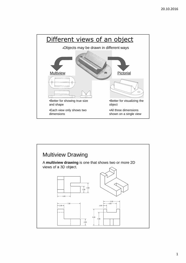
Multiview Drawing = Orthographic projection
� Multiview drawings provide the shape description of an object.
� When combined with dimensions, multiview drawings serve as the main form of communication between designers and manufacturers.
� Ability to see clearly in the mind’s eye an object
Line of sight
Projection plane
Object
Puzzle over multiple views
Multiview drawings serve as the documentation for manufacturers
– designers must NOT draw puzzle
– views should be visually balanced
20.10.2016
3
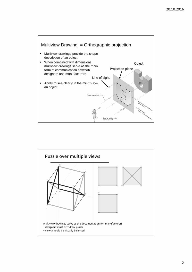
Placement of Views
Views should be visually balanced
within the working space
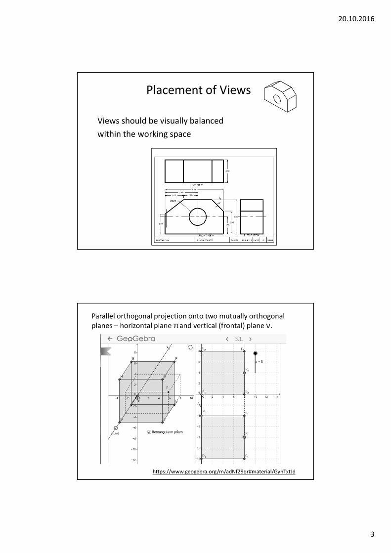
Parallel orthogonal projection onto two mutually orthogonal
planes – horizontal plane π and vertical (frontal) plane ν.
https://www.geogebra.org/m/adNf29qr#material/GyhTxtJd
20.10.2016
4
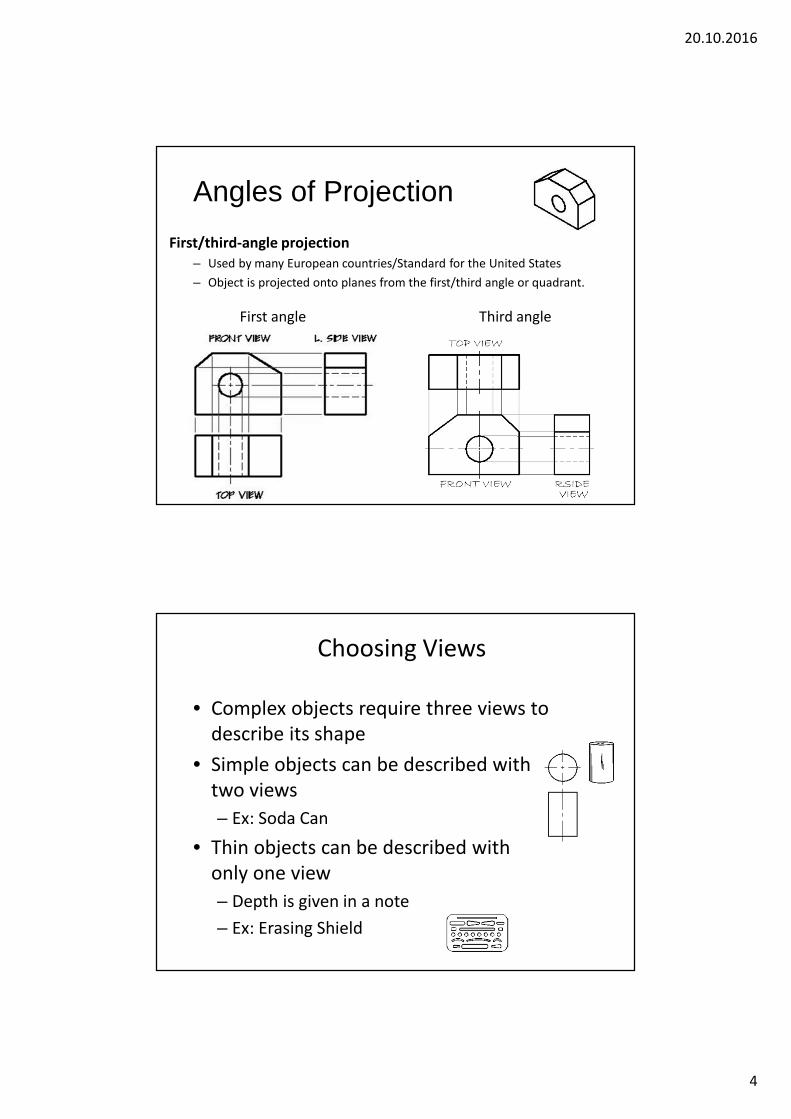
Angles of Projection
First/third-angle projection
– Used by many European countries/Standard for the United States
– Object is projected onto planes from the first/third angle or quadrant.
First angle Third angle
Choosing Views
• Complex objects require three views to
describe its shape
• Simple objects can be described with
two views
– Ex: Soda Can
• Thin objects can be described with
only one view
– Depth is given in a note
– Ex: Erasing Shield
20.10.2016
5
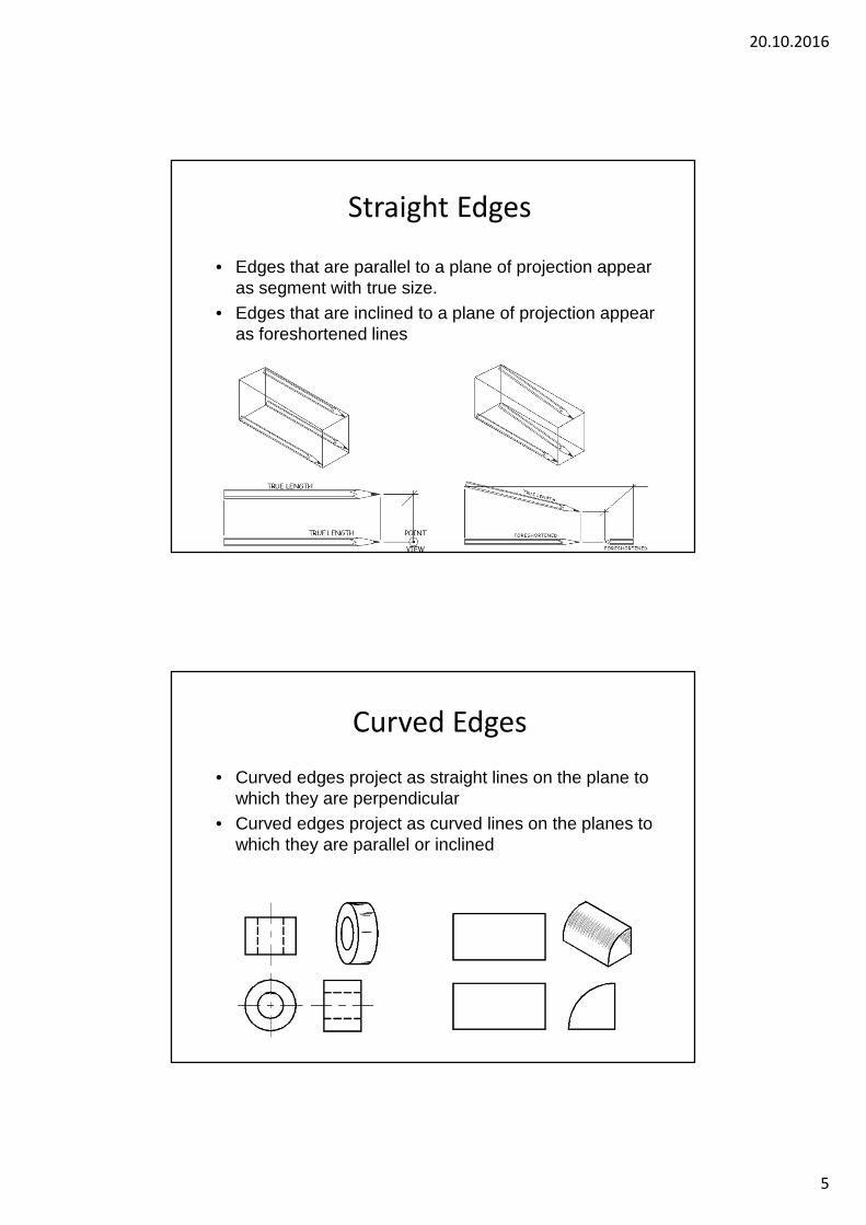
Straight Edges
• Edges that are parallel to a plane of projection appear as segment with true size.
• Edges that are inclined to a plane of projection appear as foreshortened lines
Curved Edges
• Curved edges project as straight lines on the plane to which they are perpendicular
• Curved edges project as curved lines on the planes to which they are parallel or inclined
20.10.2016
6
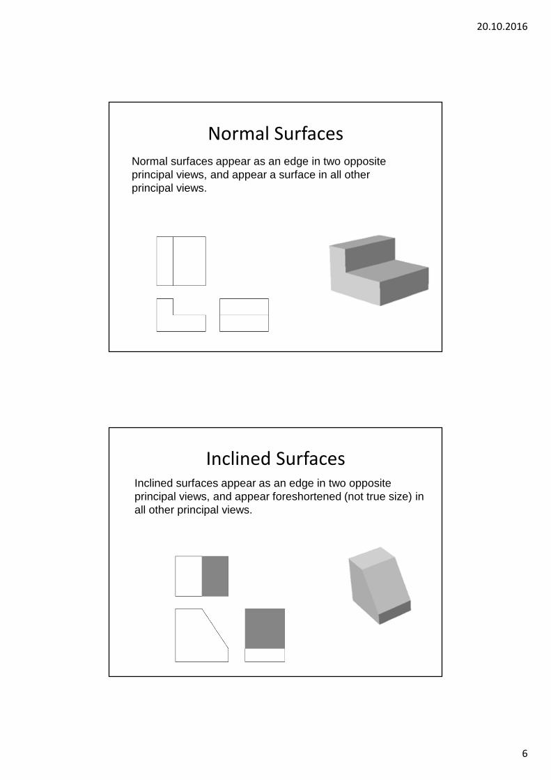
Normal Surfaces
Normal surfaces appear as an edge in two opposite principal views, and appear a surface in all other principal views.
Inclined SurfacesInclined surfaces appear as an edge in two opposite principal views, and appear foreshortened (not true size) in all other principal views.
20.10.2016
7
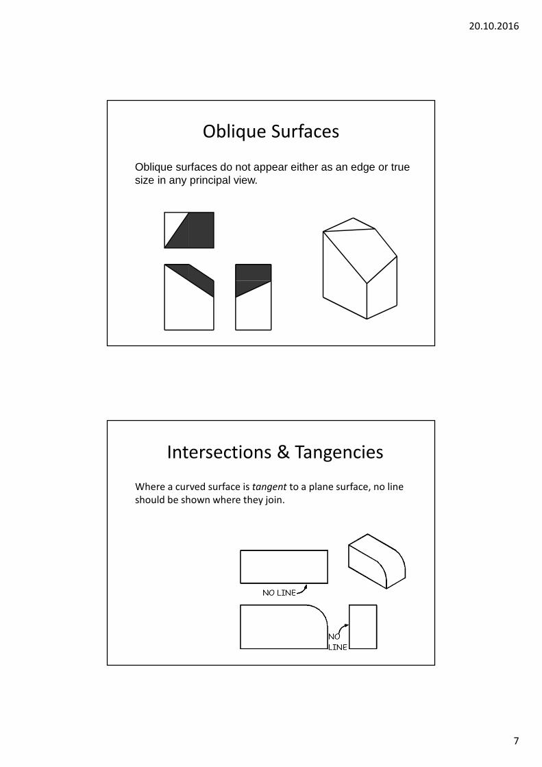
Oblique Surfaces
Oblique surfaces do not appear either as an edge or true size in any principal view.
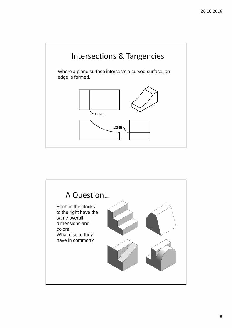
Intersections & Tangencies
Where a curved surface is tangent to a plane surface, no line
should be shown where they join.
20.10.2016
8
Intersections & Tangencies
Where a plane surface intersects a curved surface, an edge is formed.
A Question…
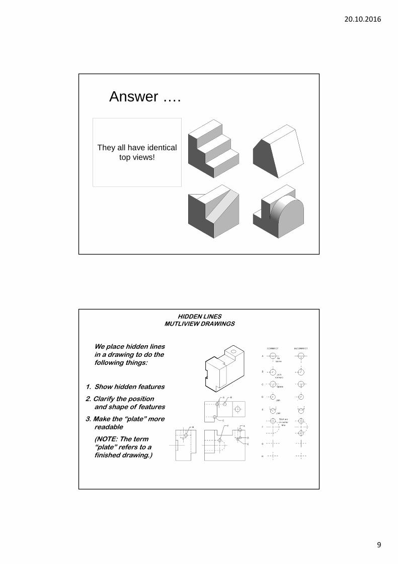
Each of the blocks to the right have the same overall dimensions and colors.What else to they have in common?
20.10.2016
9
Answer ….
They all have identical top views!
HIDDEN LINES MUTLIVIEW DRAWINGS
We place hidden lines in a drawing to do the following things:
1. Show hidden features
2. Clarify the position and shape of features
3. Make the “plate” more readable
(NOTE: The term “plate” refers to a finished drawing.)
20.10.2016
10
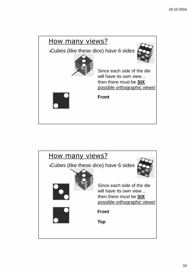
How many views?
�Cubes (like these dice) have 6 sides
Since each side of the die will have its own view…then there must be SIX possible orthographic views!
Front
How many views?
�Cubes (like these dice) have 6 sides
Since each side of the die will have its own view…then there must be SIX possible orthographic views!
Front
Top
20.10.2016
11
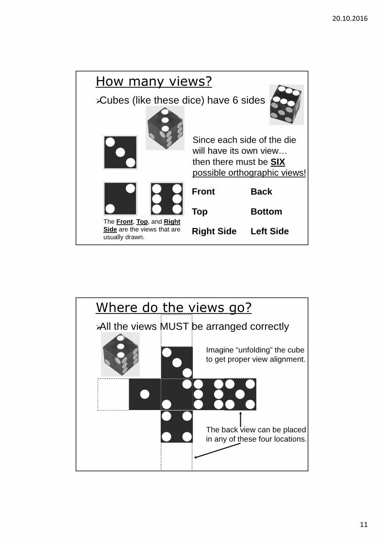
How many views?
�Cubes (like these dice) have 6 sides
Since each side of the die will have its own view…
The Front, Top, and Right Side are the views that are usually drawn.
then there must be SIX possible orthographic views!
Front
Top
Right Side
Back
Bottom
Left Side
Where do the views go?
�All the views MUST be arranged correctly
Imagine “unfolding” the cube to get proper view alignment.
The back view can be placed in any of these four locations.
20.10.2016
12
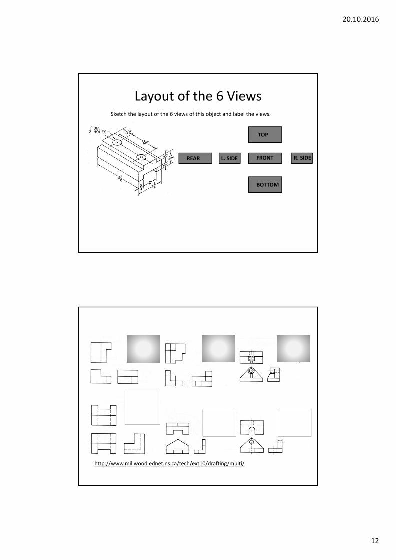
Layout of the 6 ViewsSketch the layout of the 6 views of this object and label the views.
TOP
FRONTREAR L. SIDE
BOTTOM
R. SIDE
http://www.millwood.ednet.ns.ca/tech/ext10/drafting/multi/
20.10.2016
13
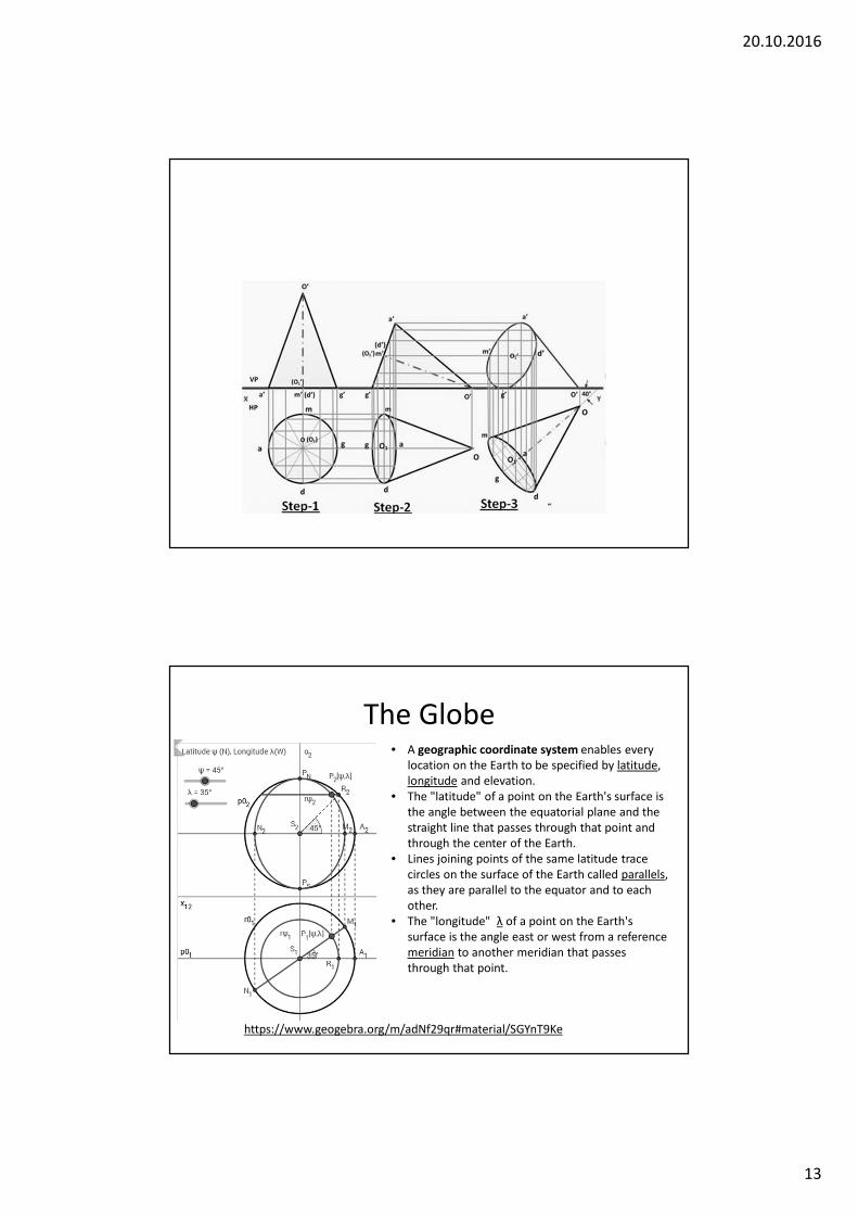
The Globe
https://www.geogebra.org/m/adNf29qr#material/SGYnT9Ke
• A geographic coordinate system enables every
location on the Earth to be specified by latitude,
longitude and elevation.
• The "latitude" of a point on the Earth's surface is
the angle between the equatorial plane and the
straight line that passes through that point and
through the center of the Earth.
• Lines joining points of the same latitude trace
circles on the surface of the Earth called parallels,
as they are parallel to the equator and to each
other.
• The "longitude" λ of a point on the Earth's
surface is the angle east or west from a reference
meridian to another meridian that passes
through that point.
20.10.2016
14
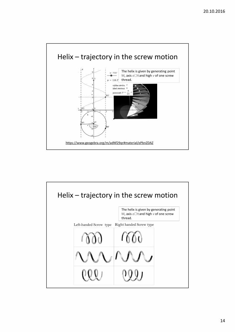
Helix – trajectory in the screw motion
https://www.geogebra.org/m/adNf29qr#material/ePbnZDAZ
The helix is given by generating point
M, axis o⊥π and high v of one screw
thread.
Helix – trajectory in the screw motion
The helix is given by generating point
M, axis o⊥π and high v of one screw
thread.
Related Documents