Automation products available: • PumpExpert • PumpDrive • Hyamaster MTC RO A 50 /8E -- 3.1 31.80 (SP) MTC A 32 /8E -- 2.1 12.65 (SP) Type series booklet 1777.5/8-10 G2 Multitec / Multitec-RO High-Pressure Pumps in Ring-Section Design Applications D General water supply D Distillate D Pressure boosting D Industry D Drinking water supply D Filter systems D Irrigation D Solvents D Heating D Fire-fighting systems D Boiler feed water D Washing systems D Warm water D Reverse osmosis D Hot water D Lubricants D Circulation D Fuels D Condensate D Process D Snow-making systems D Power plants Operating data Pump sizes DN 32 to 150 Capacities Q up to 850 m 3 /h, 236 l/s Heads H up to 630 m, (800 m) Operating temperature t --10 _C to +200 _C Operating pressures p 2 up to 63 bar 1) , (80 bar) Standard flanges DIN Suction nozzle PN 16 (JL1040) and PN 25 (GP240GH+N, 1.4408, 1.4517) Discharge nozzle PN 40 (JL1040) and PN 63 (GP240GH+N, 1.4408, 1.4517) Drilled to PN 100 (1.4317, 1.4517) Standard flanges ASME Suction nozzle Class 125 (JL1040) and Class 300 (GP240GH+N, 1.4408, 1.4517) Discharge nozzle Class 250 (JL1040) and Class 600 (GP240GH+N, 1.4408, 1.4317, 1.4517) 1) The total of inlet pressure and head at zero flow must not exceed the specified value Design Multistage centrifugal pump in ring-section design, long-coupled (baseplate-mounted) or close-coupled for horizontal installation, close--coupled or with cardan shaft for vertical installation. Axial or radial suction nozzle. Radial suction and discharge casings: Nozzles can be turned in steps of 90°. Flanges to EN and ANSI (holes and flange facing). Closed radial impellers. Size 50 and above: suction impeller in the first stage for improving the NPSH value. Bearings/Lubrication Discharge side: rolling element bearings Suction side: plain or rolling element bearings, depending on installation type Lubrication: Rolling element bearings grease lubricated, oil lubrication possible. Plain bearings are product lubricated. Shaft seal Standardised mechanical seal, uncooled or cooled, single or double. Cartridge mechanical seals possible. Uncooled gland packing, with or without barrier fluid. Designation Pump series Installation type DN discharge nozzle Number of stages/Impeller combination Hydraulics Material variant Shaft seal code Code for special variants (optional) Materials Casing: Grey cast iron, steel, stainless steel, duplex stainless steel Hydraulic components: Grey cast iron, bronze, stainless steel, duplex stainless steel Drive Electric motor 50 and 60 Hz; Diesel engine or turbine possible. Certification ISO 9001 ISO 14001 ISO 18001

Welcome message from author
This document is posted to help you gain knowledge. Please leave a comment to let me know what you think about it! Share it to your friends and learn new things together.
Transcript
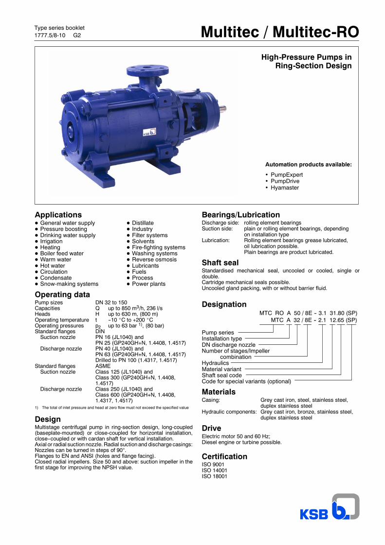
Automation products available:
• PumpExpert• PumpDrive• Hyamaster
MTC RO A 50 / 8E -- 3.1 31.80 (SP)MTC A 32 / 8E -- 2.1 12.65 (SP)
Type series booklet1777.5/8-10 G2 Multitec / Multitec-RO
High-Pressure Pumps inRing-Section Design
ApplicationsD General water supply D DistillateD Pressure boosting D IndustryD Drinking water supply D Filter systemsD Irrigation D SolventsD Heating D Fire-fighting systemsD Boiler feed water D Washing systemsD Warm water D Reverse osmosisD Hot water D LubricantsD Circulation D FuelsD Condensate D ProcessD Snow-making systems D Power plants
Operating dataPump sizes DN 32 to 150Capacities Q up to 850 m3/h, 236 l/sHeads H up to 630 m, (800 m)Operating temperature t --10 _C to +200 _COperating pressures p2 up to 63 bar 1), (80 bar)Standard flanges DINSuction nozzle PN 16 (JL1040) and
PN 25 (GP240GH+N, 1.4408, 1.4517)Discharge nozzle PN 40 (JL1040) and
PN 63 (GP240GH+N, 1.4408, 1.4517)Drilled to PN 100 (1.4317, 1.4517)
Standard flanges ASMESuction nozzle Class 125 (JL1040) and
Class 300 (GP240GH+N, 1.4408,1.4517)
Discharge nozzle Class 250 (JL1040) andClass 600 (GP240GH+N, 1.4408,1.4317, 1.4517)
1) The total of inlet pressure and head at zero flow must not exceed the specified value
DesignMultistage centrifugal pump in ring-section design, long-coupled(baseplate-mounted) or close-coupled for horizontal installation,close--coupled or with cardan shaft for vertical installation.Axial or radial suction nozzle. Radial suction and discharge casings:Nozzles can be turned in steps of 90°.Flanges to EN and ANSI (holes and flange facing).Closed radial impellers. Size 50 and above: suction impeller in thefirst stage for improving the NPSH value.
Bearings/LubricationDischarge side: rolling element bearingsSuction side: plain or rolling element bearings, depending
on installation typeLubrication: Rolling element bearings grease lubricated,
oil lubrication possible.Plain bearings are product lubricated.
Shaft sealStandardised mechanical seal, uncooled or cooled, single ordouble.Cartridge mechanical seals possible.Uncooled gland packing, with or without barrier fluid.
Designation
Pump seriesInstallation typeDN discharge nozzleNumber of stages/Impeller
combinationHydraulicsMaterial variantShaft seal codeCode for special variants (optional)
MaterialsCasing: Grey cast iron, steel, stainless steel,
duplex stainless steelHydraulic components: Grey cast iron, bronze, stainless steel,
duplex stainless steel
DriveElectric motor 50 and 60 Hz;Diesel engine or turbine possible.
CertificationISO 9001ISO 14001ISO 18001
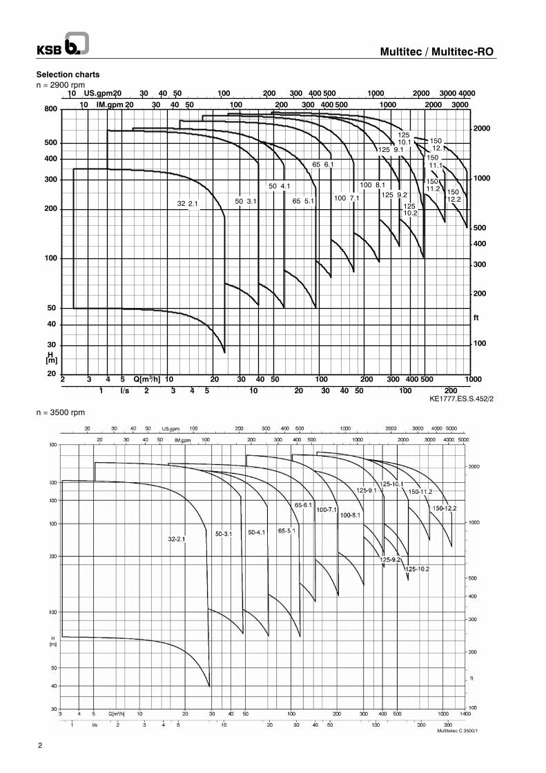
KE1777.ES.S.452/2
10 20 30 40 50 100 200 300 400 500 1000 2000 3000 4000US.gpm10 20 30 40 50 100 200 300 400 500 1000 2000 3000IM.gpm
1 2 3 4 5 10 20 30 40 50 100 200l/s2 3 4 5 10 20 30 40 50 100 200 300 400 500 1000Q[m /h]3
100
200
300
400
500
1000
2000
ft
20
30
40
50
100
200
300
400
500
800
H[m]
15012.1
15012.2
15011.1
15011.2
12510.1
12510.2
125 9.1
125 9.2100 8.1
100 7.1
65 6.1
65 5.1
50 4.1
50 3.132 2.1
Multitetec C 3500/1
Multitec / Multitec-RO
2
Selection chartsn = 2900 rpm
n = 3500 rpm
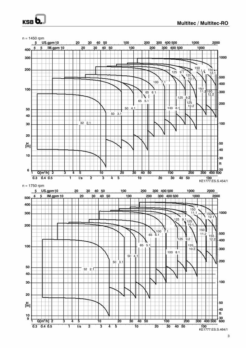
KE1777.ES.S.454/1
5 10 20 30 40 50 100 200 300 400 500 1000 2000US.gpm4 5 10 20 30 40 50 100 200 300 400 500 1000IM.gpm
0.3 0.4 0.5 1 2 3 4 5 10 20 30 40 50 100l/s
1 2 3 4 5 10 20 30 40 50 100 200 300 400 500Q[m /h]320
30
40
50
100
200
300
400
500
1000
ft
10
20
30
40
50
100
200
300
400
6
H[m]
15012.1
15012.2
15011.1
15011.2
12510.1
12510.2
125 9.1
125 9.2
100 8.1
100 7.1
65 6.1
65 5.1
50 4.1
50 3.1
32 2.1
KE1777.ES.S.464/1
5 10 20 30 40 50 100 200 300 400 500 1000 2000US.gpm4 5 10 20 30 40 50 100 200 300 400 500 1000 2000IM.gpm
0.3 0.4 0.5 1 2 3 4 5 10 20 30 40 50 100l/s
1 2 3 4 5 10 20 30 40 50 100 200 300 400 500 600Q[m /h]330
40
50
100
200
300
400
500
1000
ft10
20
30
40
50
100
200
300
400
500
9
H[m]
15012.1
15012.2
15011.1
15011.2
12510.1
12510.2
125 9.1
125 9.2
100 8.1
100 7.165 6.1
65 5.1
50 4.1
50 3.1
32 2.1
Multitec / Multitec-RO
3
n = 1450 rpm
n = 1750 rpm
Hm
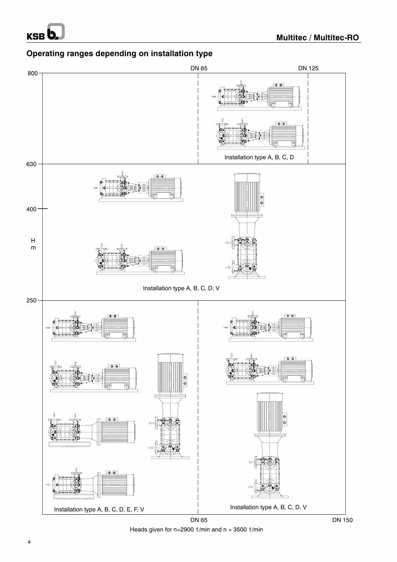
630
400
250
DN 65 DN 150
Installation type A, B, C, D, E, F, V
Installation type A, B, C, D, V
Installation type A, B, C, D, V
Heads given for n=2900 1/min and n = 3500 1/min
Installation type A, B, C, D
800DN 65 DN 125
Multitec / Multitec-RO
4
Operating ranges depending on installation type
Installation type A
Installation type B
Installation type C
Installation type D
Installation type F
Installation type E
Installation type V
3)
3)
3)
3)
3)
3)
4)
Multitec / Multitec-RO
5
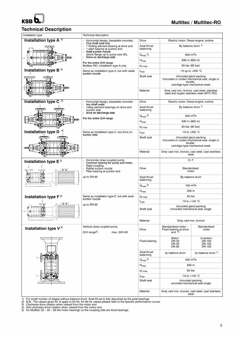
Technical DescriptionInstallation type Technical description
- Horizontal design, baseplate mounted,- One shaft seal only
Drive Electric motor, Diesel engine, turbine- One shaft seal only- 1 Rolling element bearing at drive end- 1 plain bearing at suction end- Axial suction nozzle
Axial thrustbalancing
By balance drum 1)
- Axial suction nozzle(block flange up to pump size 50),
- Drive on discharge sideQmax
2) 840 m3/h- Drive on discharge side
For the entire Q/H rangeHmax 630 m (800 m)
For the entire Q/H rangeMultitec-RO: installation type A only p2 max 63 bar (80 bar)
Same as installation type A, but with radialsuction nozzle
tmax -10 up to +200 °Csuction nozzle
Shaft seal Uncooled gland packingUncooled or cooled mechanical seal, single or
double,cartridge-type mechanical seals
Material Grey cast iron, bronze, cast steel, stainlesssteel and duplex stainless steel (MTC RO)
- Horizontal design, baseplate mounted- two shaft seals
Drive Electric motor, Diesel engine, turbine- two shaft seals- rolling element bearings on drive and
suction side- drive on discharge side
Axial thrustbalancing
By balance drum 1)
- drive on discharge side
For the entire Q/H rangeQmax
2) 840 m3/hFor the entire Q/H range
Hmax 630 m (800 m)
p2 max 63 bar (80 bar)
Same as installation type C, but drive onsuction side
tmax -10 to +200 °Csuction side
Shaft seal Uncooled gland packingUncooled or cooled mechanical seal, single or
double,cartridge-type mechanical seals
Material Grey cast iron, bronze, cast steel, cast stainlesssteel
- Horizontal close-coupled pump,- Common bearing for pump and motor
E, F- Common bearing for pump and motor,- Rigid coupling,- Radial suction nozzle- Plain bearing at suction end
Drive Standardisedmotor
up to DN 65 Axial thrustbalancing
By balance drum
Qmax2) 100 m3/h
Hmax 250 m
Same as installation type E, but with axialsuction nozzle
p2 max 40 baryp ,suction nozzle
t DN 65tmax -10 to +140 °C
up to DN 65
Shaft sealUncooled gland packing
Uncooled mechanical seal, single
Material Grey cast iron, bronze
Vertical close-coupled pump
Q/H range2): max. 200 kWDrive
Standardised motor --Fixed bearing at drive
end 5)
Standardisedmotor
Fixed bearingMotor:DN 32DN 50DN 65
in lantern:DN 100DN 125DN 150
Axial thrustbalancing
by balance drum by balance drum 1)
Qmax2) 400 m3/h
Hmax 630 m
p2 max 63 bar
tmax -10 to +140 °C
Shaft seal Uncooled packing;uncooled mechanical seal single
Material Grey cast iron, bronze, cast steel, cast stainlesssteel
1) For small number of stages without balance drum: Axial thrust is fully absorbed by the axial bearings.2) N.B.: The values given for Q apply to 50 Hz; for 60 Hz values please refer to the specific performance curves.3) Clockwise drive rotation when viewed from the motor end.4) Anti-clockwise drive rotation when viewed from the motor end.5) On Multitec 32 -- 50 -- 65 the motor bearings on the coupling side are fixed bearings.
ASME Class 300
ASME Class 600
ASME Class 125
ASME Class250
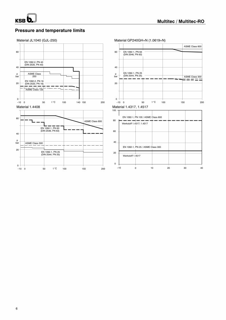
Material JL1040 (GJL-250)
20
0
40
60
pbar
--10 0 50 100 150 200
EN 1092-2, PN 40(DIN 2535, PN 40)
EN 1092-2, PN 16(DIN 2533, PN 16)
t °C
EN 1092-1, PN 63(DIN 2546, PN 63)
20
0
40
60
pbar
--10 0 50 100 150 200
ASME Class 600
ASME Class 300
EN 1092-1, PN 25(DIN 2544, PN 25)
t °C
Material GP240GH+N (1.0619+N)
EN 1092-1, PN 63(DIN 2546, PN 63)
20
0
40
60
pbar
--10 0 50 100 150 200t °C
EN 1092-1, PN 25(DIN 2544, PN 25)
Material 1.4408
140
0
20
40
60
100
--10 0 10 20 30 40
80Werkstoff 1.4317; 1.4517
Werkstoff 1.4517
EN 1092-1, PN 25 / ASME Class 300
EN 1092-1, PN 100 / ASME Class 600
Material 1.4317, 1.4517
Multitec / Multitec-RO
6
Pressure and temperature limits
Multitec / Multitec-RO
7
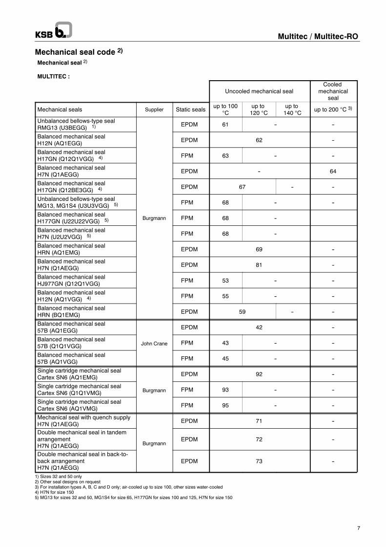
Mechanical seal code 2)
Mechanical seal 2)
MULTITEC :
Uncooled mechanical sealCooled
mechanicalseal
Mechanical seals Supplier Static sealsup to 100
°Cup to120 °C
up to140 °C
up to 200 °C 3)
Unbalanced bellows-type sealRMG13 (U3BEGG) 1) EPDM 61 -- --
Balanced mechanical sealH12N (AQ1EGG) EPDM 62 --
Balanced mechanical sealH17GN (Q12Q1VGG) 4) FPM 63 -- --
Balanced mechanical sealH7N (Q1AEGG) EPDM -- 64
Balanced mechanical sealH17GN (Q12BE3GG) 4) EPDM 67 -- --
Unbalanced bellows-type sealMG13, MG1S4 (U3U3VGG) 5) FPM 68 -- --
Balanced mechanical sealH177GN (U22U22VGG) 5) Burgmann FPM 68 --
Balanced mechanical sealH7N (U2U2VGG) 5) FPM 68 --
Balanced mechanical sealHRN (AQ1EMG) EPDM 69 --
Balanced mechanical sealH7N (Q1AEGG) EPDM 81 --
Balanced mechanical sealHJ977GN (Q12Q1VGG) FPM 53 -- --
Balanced mechanical sealH12N (AQ1VGG) 4) FPM 55 -- --
Balanced mechanical sealHRN (BQ1EMG) EPDM 59 -- --
Balanced mechanical seal57B (AQ1EGG) EPDM 42 --
Balanced mechanical seal57B (Q1Q1VGG) John Crane FPM 43 -- --
Balanced mechanical seal57B (AQ1VGG) FPM 45 -- --
Single cartridge mechanical sealCartex SN6 (AQ1EMG) EPDM 92 --
Single cartridge mechanical sealCartex SN6 (Q1Q1VMG) Burgmann FPM 93 -- --
Single cartridge mechanical sealCartex SN6 (AQ1VMG) FPM 95 -- --
Mechanical seal with quench supplyH7N (Q1AEGG) EPDM 71 --
Double mechanical seal in tandemarrangementH7N (Q1AEGG) Burgmann
EPDM 72 --
Double mechanical seal in back-to-back arrangementH7N (Q1AEGG)
EPDM 73 --
1) Sizes 32 and 50 only2) Other seal designs on request3) For installation types A, B, C and D only; air-cooled up to size 100, other sizes water-cooled4) H7N for size 1505) MG13 for sizes 32 and 50, MG1S4 for size 65, H177GN for sizes 100 and 125, H7N for size 150
Multitec / Multitec-RO
8
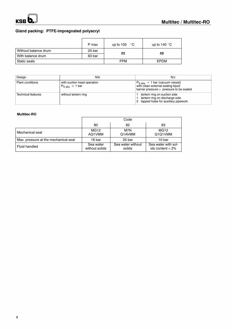
Gland packing: PTFE-impregnated polyacryl
P max up to 100 _C up to 140 _C
Without balance drum 25 bar65 66
With balance drum 63 bar65 66
Static seals FPM EPDM
Design N/b N/c
Plant conditions with suction head operationPS abs.≥ 1 bar
PS abs.< 1 bar (vacuum vessel)with clean external sealing liquidbarrier pressure > pressure to be sealed
Technical features without lantern ring 1 lantern ring on suction side1 lantern ring on discharge side2 tapped holes for auxiliary pipework
Multitec-RO
Code
80 82 83
Mechanical sealMG12
AQ1VMMM7N
Q1AVMMMG12
Q1Q1VMM
Max. pressure at the mechanical seal 16 bar 25 bar 10 bar
Fluid handledSea water
without solidsSea water without
solidsSea water with sol-ids content < 2%
Multitec / Multitec-RO
9
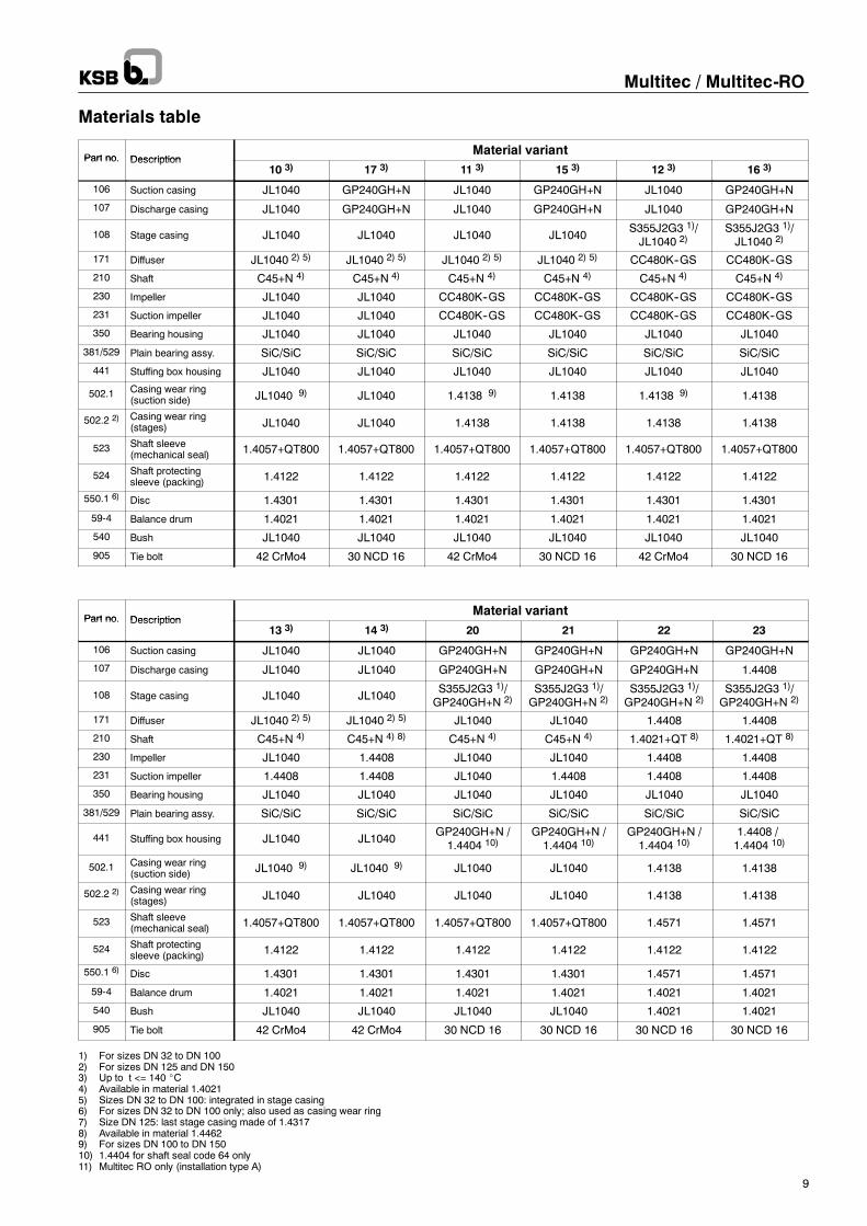
Materials table
Part no. DescriptionMaterial variant
Part no. Description10 3) 17 3) 11 3) 15 3) 12 3) 16 3)
106 Suction casing JL1040 GP240GH+N JL1040 GP240GH+N JL1040 GP240GH+N
107 Discharge casing JL1040 GP240GH+N JL1040 GP240GH+N JL1040 GP240GH+N
108 Stage casing JL1040 JL1040 JL1040 JL1040S355J2G3 1)/JL1040 2)
S355J2G3 1)/JL1040 2)
171 Diffuser JL1040 2) 5) JL1040 2) 5) JL1040 2) 5) JL1040 2) 5) CC480K--GS CC480K--GS
210 Shaft C45+N 4) C45+N 4) C45+N 4) C45+N 4) C45+N 4) C45+N 4)
230 Impeller JL1040 JL1040 CC480K--GS CC480K--GS CC480K--GS CC480K--GS
231 Suction impeller JL1040 JL1040 CC480K--GS CC480K--GS CC480K--GS CC480K--GS
350 Bearing housing JL1040 JL1040 JL1040 JL1040 JL1040 JL1040
381/529 Plain bearing assy. SiC/SiC SiC/SiC SiC/SiC SiC/SiC SiC/SiC SiC/SiC
441 Stuffing box housing JL1040 JL1040 JL1040 JL1040 JL1040 JL1040
502.1 Casing wear ring(suction side) JL1040 9) JL1040 1.4138 9) 1.4138 1.4138 9) 1.4138
502.2 2) Casing wear ring(stages) JL1040 JL1040 1.4138 1.4138 1.4138 1.4138
523 Shaft sleeve(mechanical seal) 1.4057+QT800 1.4057+QT800 1.4057+QT800 1.4057+QT800 1.4057+QT800 1.4057+QT800
524 Shaft protectingsleeve (packing) 1.4122 1.4122 1.4122 1.4122 1.4122 1.4122
550.1 6) Disc 1.4301 1.4301 1.4301 1.4301 1.4301 1.4301
59-4 Balance drum 1.4021 1.4021 1.4021 1.4021 1.4021 1.4021
540 Bush JL1040 JL1040 JL1040 JL1040 JL1040 JL1040
905 Tie bolt 42 CrMo4 30 NCD 16 42 CrMo4 30 NCD 16 42 CrMo4 30 NCD 16
Part no. DescriptionMaterial variant
Part no. Description13 3) 14 3) 20 21 22 23
106 Suction casing JL1040 JL1040 GP240GH+N GP240GH+N GP240GH+N GP240GH+N
107 Discharge casing JL1040 JL1040 GP240GH+N GP240GH+N GP240GH+N 1.4408
108 Stage casing JL1040 JL1040S355J2G3 1)/GP240GH+N 2)
S355J2G3 1)/GP240GH+N 2)
S355J2G3 1)/GP240GH+N 2)
S355J2G3 1)/GP240GH+N 2)
171 Diffuser JL1040 2) 5) JL1040 2) 5) JL1040 JL1040 1.4408 1.4408
210 Shaft C45+N 4) C45+N 4) 8) C45+N 4) C45+N 4) 1.4021+QT 8) 1.4021+QT 8)
230 Impeller JL1040 1.4408 JL1040 JL1040 1.4408 1.4408
231 Suction impeller 1.4408 1.4408 JL1040 1.4408 1.4408 1.4408
350 Bearing housing JL1040 JL1040 JL1040 JL1040 JL1040 JL1040
381/529 Plain bearing assy. SiC/SiC SiC/SiC SiC/SiC SiC/SiC SiC/SiC SiC/SiC
441 Stuffing box housing JL1040 JL1040GP240GH+N /1.4404 10)
GP240GH+N /1.4404 10)
GP240GH+N /1.4404 10)
1.4408 /1.4404 10)
502.1 Casing wear ring(suction side) JL1040 9) JL1040 9) JL1040 JL1040 1.4138 1.4138
502.2 2) Casing wear ring(stages) JL1040 JL1040 JL1040 JL1040 1.4138 1.4138
523 Shaft sleeve(mechanical seal) 1.4057+QT800 1.4057+QT800 1.4057+QT800 1.4057+QT800 1.4571 1.4571
524 Shaft protectingsleeve (packing) 1.4122 1.4122 1.4122 1.4122 1.4122 1.4122
550.1 6) Disc 1.4301 1.4301 1.4301 1.4301 1.4571 1.4571
59-4 Balance drum 1.4021 1.4021 1.4021 1.4021 1.4021 1.4021
540 Bush JL1040 JL1040 JL1040 JL1040 1.4021 1.4021
905 Tie bolt 42 CrMo4 42 CrMo4 30 NCD 16 30 NCD 16 30 NCD 16 30 NCD 16
1) For sizes DN 32 to DN 1002) For sizes DN 125 and DN 1503) Up to t <= 140 _C4) Available in material 1.40215) Sizes DN 32 to DN 100: integrated in stage casing6) For sizes DN 32 to DN 100 only; also used as casing wear ring7) Size DN 125: last stage casing made of 1.43178) Available in material 1.44629) For sizes DN 100 to DN 15010) 1.4404 for shaft seal code 64 only11) Multitec RO only (installation type A)
Multitec / Multitec-RO
10
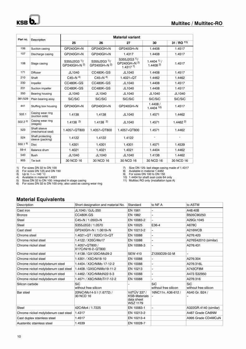
Part no. DescriptionMaterial variant
Part no. Description25 26 27 30 31 / RO 11)
106 Suction casing GP240GH+N GP240GH+N GP240GH+N 1.4408 1.4517
107 Discharge casing GP240GH+N GP240GH+N 1.4317 1.4408 1.4517
108 Stage casingS355J2G3 1)/GP240GH+N 2)
S355J2G3 1)/GP240GH+N 2)
S355J2G3 1)/GP240GH+N 2)
1.4317 7)
1.4404 1) /1.4408 2) 1.4517
171 Diffuser JL1040 CC480K--GS JL1040 1.4408 1.4517
210 Shaft C45+N 4) C45+N 4) 1.4021+QT 1.4462 1.4462
230 Impeller CC480K--GS CC480K--GS JL1040 1.4408 1.4517
231 Suction impeller CC480K--GS CC480K--GS JL1040 1.4408 1.4517
350 Bearing housing JL1040 JL1040 JL1040 JL1040 JL1040
381/529 Plain bearing assy. SiC/SiC SiC/SiC SiC/SiC SiC/SiC SiC/SiC
441 Stuffing box housing GP240GH+N GP240GH+N GP240GH+N1.4408 /1.4404 10) 1.4517
502.1 Casing wear ring(suction side) 1.4138 1.4138 JL1040 1.4571 1.4462
502.2 2) Casing wear ring(stages) 1.4138 2) 1.4138 2) JL1040 1.4571 1.4462 2)
523 Shaft sleeve(mechanical seal) 1.4057+QT800 1.4057+QT800 1.4057+QT800 1.4571 1.4462
524 Shaft protectingsleeve (packing) 1.4122 1.4122 1.4122 -- --
550.1 6) Disc 1.4301 1.4301 1.4301 1.4571 1.4539
59-4 Balance drum 1.4021 1.4021 1.4021 1.4404 1.4462
540 Bush JL1040 JL1040 JL1040 1.4138 1.4462
905 Tie bolt 30 NCD 16 30 NCD 16 30 NCD 16 30 NCD 16 30 NCD 16
1) For sizes DN 32 to DN 1002) For sizes DN 125 and DN 1503) Up to t <= 140 _C4) Available in material 1.40215) Sizes DN 32 to DN 100: integrated in stage casing6) For sizes DN 32 to DN 100 only; also used as casing wear ring
7) Size DN 125: last stage casing made of 1.43178) Available in material 1.44629) For sizes DN 100 to DN 15010) 1.4404 for shaft seal code 64 only11) Multitec RO only (installation type A)
Material EquivalentsDescription Short designation and material No. Standard to NF A to ASTM
Cast iron JL1040 / GJL-250 EN 1561 -- A48:40BBronze CC480K-GS EN 1982 -- B505C90250
Steel C45+N / 1.0503+N EN 10083-2 -- A29Gr.1045
Steel S355J2G3 / 1.0570 EN 10025 E36-4 A678C
Cast steel GP240GH+N / 1.0619+N EN 10213-2 -- A216WCB
Chrome steel 1.4021+QT / X20Cr13+QT EN 10088 -- A276:420
Chrome nickel steel 1.4122 / X35CrMo17 EN 10088 -- A276S42010 (similar)
Chrome nickel steel 1.4057+QT800 /X17CrNi16-2--QT800
EN 10088-3 -- A276:431
Chrome nickel steel 1.4138 / GX120CrMo29-2 SEW 410 Z1200D29-02-M --
Chrome nickel steel 1.4301 / X5CrNi18-10 EN 10088 -- A276:304
Chrome nickel molybdenum steel 1.4404 / X2CrNiMo 17-12-2 EN 10088 -- A276:316L
Chrome nickel molybdenum cast steel 1.4408 / GX5CrNiMo19-11-2 EN 10213 -- A743CF8M
Chrome nickel molybdenum steel 1.4462 / X2CrNiMoN22-5-3 EN 10088 -- A473 S32950
Chrome nickel molybdenum steel 1.4571 / X6CrNiMoTi17-12-2 EN 10088 -- A276:316
Silicon carbide SiCwithout free silicon
-- SiCwithout free silicon
SiCwithout free silicon
Bar steel 20NiCrMo14-5 I (1.6772) /30 NCD 16
VdTÜV 337 /KSB-Materialsdata sheetWSZ 1179
16NC11n. A36-612 /--
A540 Gr. B24 /--
Steel 42CrMo4 / 1.7225 EN 10083-1 -- A322GR.4140 (similar)
Chrome nickel molybdenum cast steel 1.4317 EN 10213-2 A487 Grade CA6NM
Cast duplex stainless steel 1.4517 EN 10213-4 A995 Grade CD4MCuN
Austenitic stainless steel 1.4539 EN 10028-7
1777:51777:7
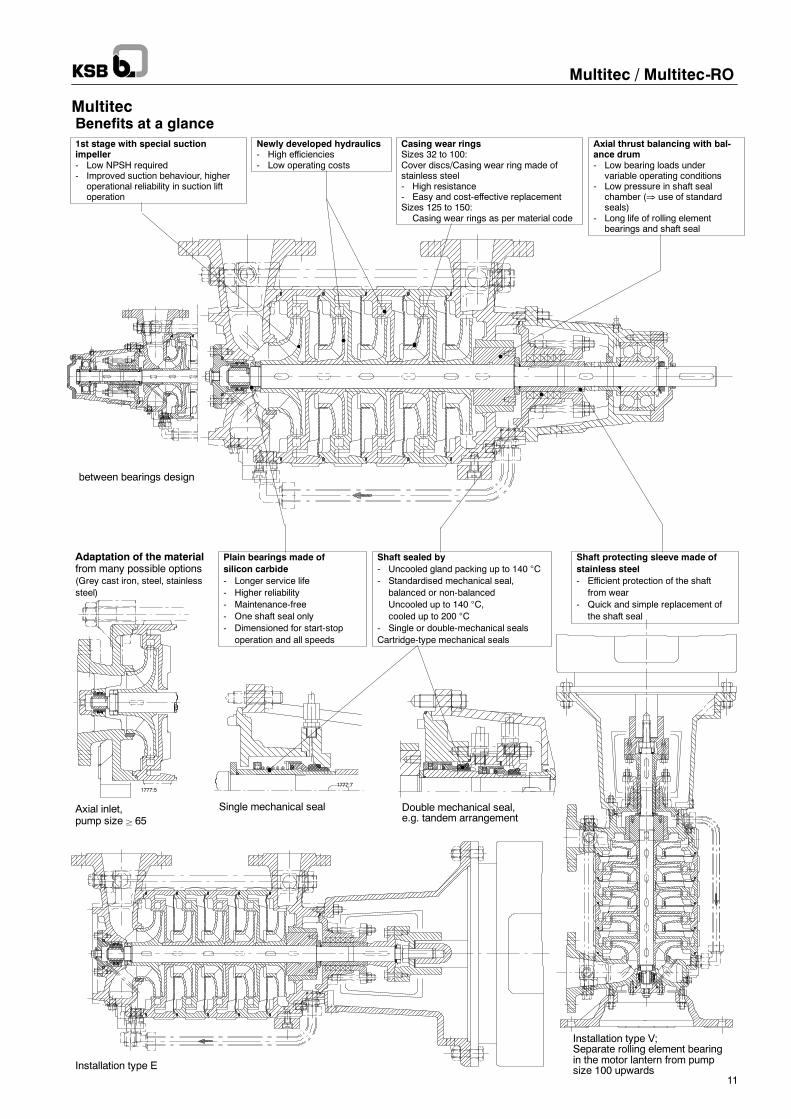
1st stage with special suctionimpeller- Low NPSH required- Improved suction behaviour, higher
operational reliability in suction liftoperation
Newly developed hydraulics- High efficiencies- Low operating costs
Casing wear ringsSizes 32 to 100:Cover discs/Casing wear ring made ofstainless steel- High resistance- Easy and cost-effective replacementSizes 125 to 150:
Casing wear rings as per material code
Axial thrust balancing with bal-ance drum- Low bearing loads under
variable operating conditions- Low pressure in shaft seal
chamber (⇒ use of standardseals)
- Long life of rolling elementbearings and shaft seal
between bearings design
Adaptation of the materialfrom many possible options(Grey cast iron, steel, stainlesssteel)
Plain bearings made ofsilicon carbide- Longer service life- Higher reliability- Maintenance-free- One shaft seal only- Dimensioned for start-stop
operation and all speeds
Shaft sealed by- Uncooled gland packing up to 140 °C- Standardised mechanical seal,
balanced or non-balancedUncooled up to 140 °C,cooled up to 200 °C
- Single or double-mechanical sealsCartridge-type mechanical seals
Shaft protecting sleeve made ofstainless steel- Efficient protection of the shaft
from wear- Quick and simple replacement of
the shaft seal
Axial inlet,pump size ² 65
Installation type E
Single mechanical seal Double mechanical seal,e.g. tandem arrangement
Installation type V;Separate rolling element bearingin the motor lantern from pumpsize 100 upwards
Benefits at a glance
Multitec / Multitec-RO
11
Multitec
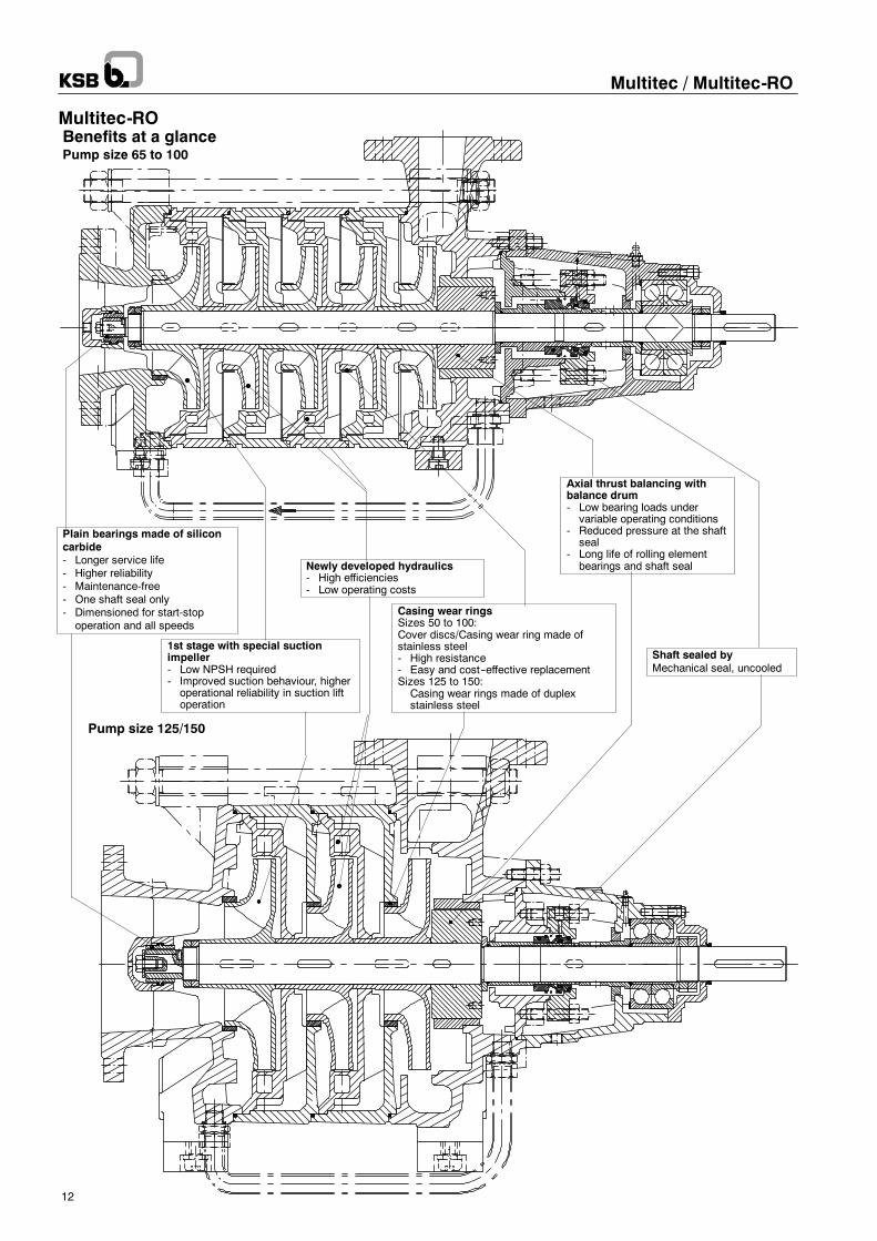
Pump size 125/150
Pump size 65 to 100
1st stage with special suctionimpeller- Low NPSH required- Improved suction behaviour, higheroperational reliability in suction liftoperation
Casing wear ringsSizes 50 to 100:Cover discs/Casing wear ring made ofstainless steel- High resistance- Easy and cost--effective replacementSizes 125 to 150:Casing wear rings made of duplexstainless steel
Axial thrust balancing withbalance drum- Low bearing loads undervariable operating conditions
- Reduced pressure at the shaftseal
- Long life of rolling elementbearings and shaft sealNewly developed hydraulics
- High efficiencies- Low operating costs
Plain bearings made of siliconcarbide- Longer service life- Higher reliability- Maintenance-free- One shaft seal only- Dimensioned for start-stopoperation and all speeds
Shaft sealed byMechanical seal, uncooled
Benefits at a glance
Multitec / Multitec-RO
12
Multitec-RO
Multitec / Multitec-RO
13
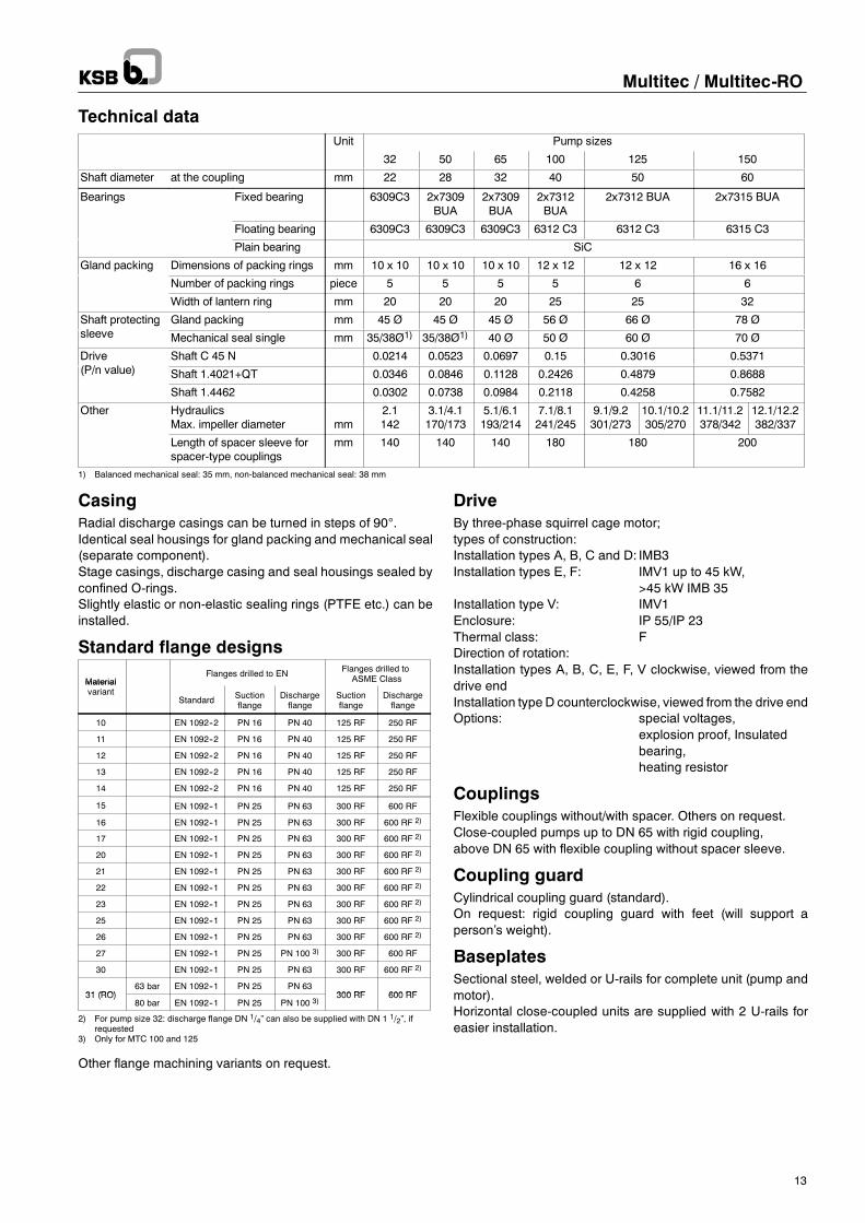
Technical dataUnit Pump sizes
32 50 65 100 125 150
Shaft diameter at the coupling mm 22 28 32 40 50 60
Bearings Fixed bearing 6309C3 2x7309BUA
2x7309BUA
2x7312BUA
2x7312 BUA 2x7315 BUA
Floating bearing 6309C3 6309C3 6309C3 6312 C3 6312 C3 6315 C3
Plain bearing SiC
Gland packing Dimensions of packing rings mm 10 x 10 10 x 10 10 x 10 12 x 12 12 x 12 16 x 16
Number of packing rings piece 5 5 5 5 6 6
Width of lantern ring mm 20 20 20 25 25 32
Shaft protectingl
Gland packing mm 45 Ø 45 Ø 45 Ø 56 Ø 66 Ø 78 Øp gsleeve Mechanical seal single mm 35/38Ø1) 35/38Ø1) 40 Ø 50 Ø 60 Ø 70 Ø
Drive(P/ l )
Shaft C 45 N 0.0214 0.0523 0.0697 0.15 0.3016 0.5371(P/n value) Shaft 1.4021+QT 0.0346 0.0846 0.1128 0.2426 0.4879 0.8688
Shaft 1.4462 0.0302 0.0738 0.0984 0.2118 0.4258 0.7582
Other HydraulicsMax. impeller diameter mm
2.1142
3.1/4.1170/173
5.1/6.1193/214
7.1/8.1241/245
9.1/9.2301/273
10.1/10.2305/270
11.1/11.2378/342
12.1/12.2382/337
Length of spacer sleeve forspacer-type couplings
mm 140 140 140 180 180 200
1) Balanced mechanical seal: 35 mm, non-balanced mechanical seal: 38 mm
CasingRadial discharge casings can be turned in steps of 90°.Identical seal housings for gland packing and mechanical seal(separate component).Stage casings, discharge casing and seal housings sealed byconfined O-rings.Slightly elastic or non-elastic sealing rings (PTFE etc.) can beinstalled.
Standard flange designs
MaterialFlanges drilled to EN Flanges drilled to
ASME ClassMaterialvariant
Standard Suctionflange
Dischargeflange
Suctionflange
Dischargeflange
10 EN 1092--2 PN 16 PN 40 125 RF 250 RF
11 EN 1092--2 PN 16 PN 40 125 RF 250 RF
12 EN 1092--2 PN 16 PN 40 125 RF 250 RF
13 EN 1092--2 PN 16 PN 40 125 RF 250 RF
14 EN 1092--2 PN 16 PN 40 125 RF 250 RF
15 EN 1092--1 PN 25 PN 63 300 RF 600 RF
16 EN 1092--1 PN 25 PN 63 300 RF 600 RF 2)
17 EN 1092--1 PN 25 PN 63 300 RF 600 RF 2)
20 EN 1092--1 PN 25 PN 63 300 RF 600 RF 2)
21 EN 1092--1 PN 25 PN 63 300 RF 600 RF 2)
22 EN 1092--1 PN 25 PN 63 300 RF 600 RF 2)
23 EN 1092--1 PN 25 PN 63 300 RF 600 RF 2)
25 EN 1092--1 PN 25 PN 63 300 RF 600 RF 2)
26 EN 1092--1 PN 25 PN 63 300 RF 600 RF 2)
27 EN 1092--1 PN 25 PN 100 3) 300 RF 600 RF
30 EN 1092--1 PN 25 PN 63 300 RF 600 RF 2)
31 (RO)63 bar EN 1092--1 PN 25 PN 63
300 RF 600 RF31 (RO)80 bar EN 1092--1 PN 25 PN 100 3)
300 RF 600 RF
2) For pump size 32: discharge flange DN 1/4” can also be supplied with DN 1 1/2”, ifrequested
3) Only for MTC 100 and 125
Other flange machining variants on request.
DriveBy three-phase squirrel cage motor;types of construction:Installation types A, B, C and D: IMB3Installation types E, F: IMV1 up to 45 kW,
>45 kW IMB 35Installation type V: IMV1Enclosure: IP 55/IP 23Thermal class: FDirection of rotation:Installation types A, B, C, E, F, V clockwise, viewed from thedrive endInstallation type D counterclockwise, viewed from the drive endOptions: special voltages,
explosion proof, Insulatedbearing,heating resistor
CouplingsFlexible couplings without/with spacer. Others on request.Close-coupled pumps up to DN 65 with rigid coupling,above DN 65 with flexible coupling without spacer sleeve.
Coupling guardCylindrical coupling guard (standard).On request: rigid coupling guard with feet (will support aperson’s weight).
BaseplatesSectional steel, welded or U-rails for complete unit (pump andmotor).Horizontal close-coupled units are supplied with 2 U-rails foreasier installation.
L
Multitec / Multitec-RO
14
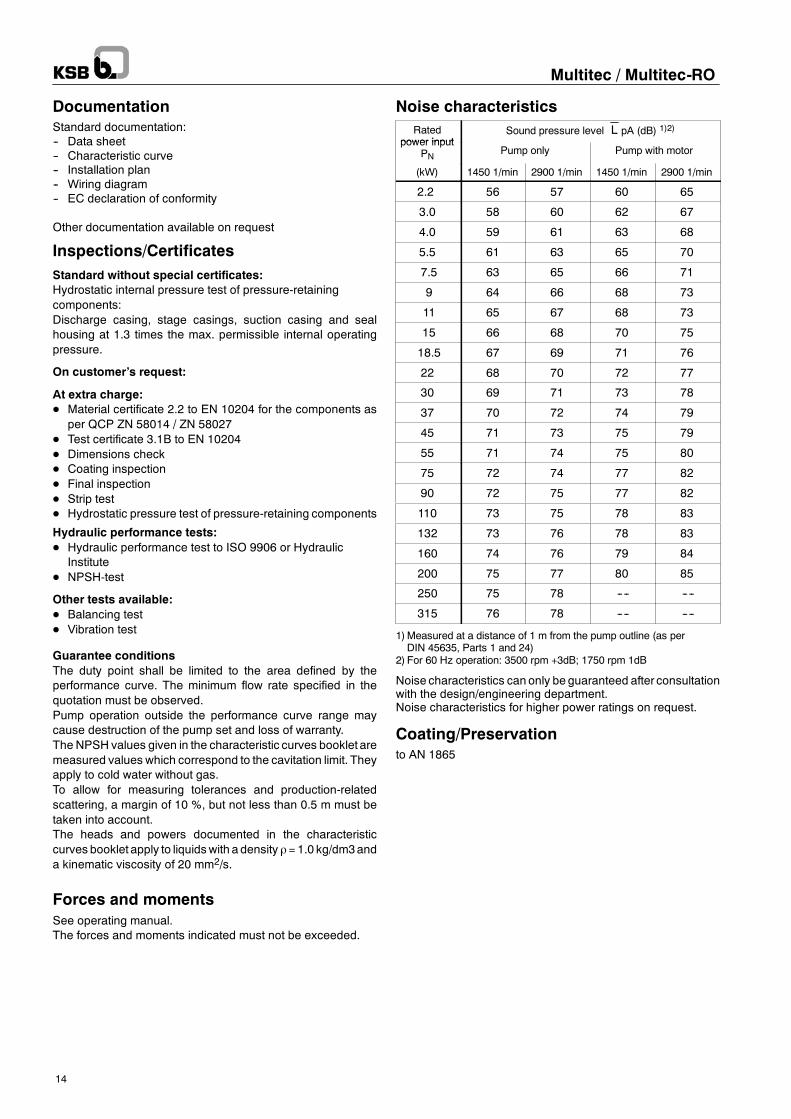
DocumentationStandard documentation:-- Data sheet-- Characteristic curve-- Installation plan-- Wiring diagram-- EC declaration of conformity
Other documentation available on request
Inspections/CertificatesStandard without special certificates:Hydrostatic internal pressure test of pressure-retainingcomponents:Discharge casing, stage casings, suction casing and sealhousing at 1.3 times the max. permissible internal operatingpressure.
On customer’s request:
At extra charge:D Material certificate 2.2 to EN 10204 for the components as
per QCP ZN 58014 / ZN 58027D Test certificate 3.1B to EN 10204D Dimensions checkD Coating inspectionD Final inspectionD Strip testD Hydrostatic pressure test of pressure-retaining components
Hydraulic performance tests:D Hydraulic performance test to ISO 9906 or Hydraulic
InstituteD NPSH-test
Other tests available:D Balancing testD Vibration test
Guarantee conditionsThe duty point shall be limited to the area defined by theperformance curve. The minimum flow rate specified in thequotation must be observed.Pump operation outside the performance curve range maycause destruction of the pump set and loss of warranty.The NPSH values given in the characteristic curves booklet aremeasured values which correspond to the cavitation limit. Theyapply to cold water without gas.To allow for measuring tolerances and production-relatedscattering, a margin of 10 %, but not less than 0.5 m must betaken into account.The heads and powers documented in the characteristiccurves booklet apply to liquidswith a density ρ= 1.0 kg/dm3anda kinematic viscosity of 20 mm2/s.
Forces and momentsSee operating manual.The forces and moments indicated must not be exceeded.
Noise characteristicsRated
power inputSound pressure level pA (dB) 1)2)
power inputPN Pump only Pump with motor
(kW) 1450 1/min 2900 1/min 1450 1/min 2900 1/min
2.2 56 57 60 65
3.0 58 60 62 67
4.0 59 61 63 68
5.5 61 63 65 70
7.5 63 65 66 71
9 64 66 68 73
11 65 67 68 73
15 66 68 70 75
18.5 67 69 71 76
22 68 70 72 77
30 69 71 73 78
37 70 72 74 79
45 71 73 75 79
55 71 74 75 80
75 72 74 77 82
90 72 75 77 82
110 73 75 78 83
132 73 76 78 83
160 74 76 79 84
200 75 77 80 85
250 75 78 ---- ----
315 76 78 ---- ----
1)Measured at a distance of 1 m from the pump outline (as perDIN 45635, Parts 1 and 24)
2) For 60 Hz operation: 3500 rpm +3dB; 1750 rpm 1dB
Noise characteristics can only be guaranteed after consultationwith the design/engineering department.Noise characteristics for higher power ratings on request.
Coating/Preservationto AN 1865
Examples of nozzleposition codes in theselection software:
A - 0
0 - 0
L - 0
R - L
Fig.
1
2
3
4
1 = turned by 180°
2 = same position
3 = turned by 90° to the left
4 = turned by 90° to the right
Fig.
Fig. Fig.
Multitec / Multitec-RO
15
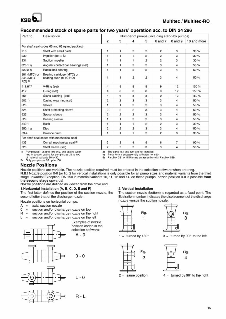
Recommended stock of spare parts for two years’ operation acc. to DIN 24 296Part no. Description Number of pumps (including stand-by pumps)
2 3 4 5 6 and 7 8 and 9 10 and more
For shaft seal codes 65 and 66 (gland packing)
210 Shaft with small parts 1 1 2 2 2 3 30 %
230 Impeller (set = S) 1 1 1 2 2 3 30 %
231 Suction impeller 1 1 1 2 2 3 30 %
320.1 4) Angular contact ball bearings (set) 1 1 2 2 3 4 50 %
320.2 4) Radial ball bearing 1 1 2 2 3 4 50 %
381 (MTC) or545 (MTCRO) 5)
Bearing cartridge (MTC) orbearing bush (MTC RO) 1 1 2 2 3 4 50 %
411.6/.7 V-Ring (set) 4 8 8 8 9 12 150 %
412 O-ring (set) 4 8 8 8 9 12 150 %
461 Gland packing (set) 4 6 8 8 9 12 150 %
502 1) Casing wear ring (set) 2 2 2 3 3 4 50 %
520 Sleeve 1 1 2 2 3 4 50 %
524 Shaft protecting sleeve 2 2 2 3 3 4 50 %
525 Spacer sleeve 2 2 2 3 3 4 50 %
529 Bearing sleeve 1 1 2 2 3 4 50 %
540.1 Bush 1 1 1 2 2 3 30 %
550.1 2) Disc 2 2 2 3 3 4 50 %
59-4 Balance drum 1 1 1 2 2 3 30 %
For shaft seal codes with mechanical seal
433 Compl. mechanical seal 3) 2 3 4 5 6 7 90 %
523 Shaft sleeve (set) 2 2 2 3 3 4 50 %
1) Pump sizes 125 and 150 only, and casing wear 3) The parts 461 and 524 are not installedring in suction casing for pump sizes 32 to 100 4) Parts form a subassembly with part no. 520of material variants 20 to 30. 5) Part No. 381 or 545 forms an assembly with Part No. 529.
2) Only pump sizes 32 up to 100
Nozzle PositionsNozzle positions are variable. The nozzle position required must be entered in the selection software when ordering.N.B.! Nozzle position 0-0 (or fig. 2 for vertical installation) is only possible for all pump sizes and material variants from the thirdstage upwards! Exception: DN 150 in material variants 10, 11, 12 and 14: on these pumps, nozzle position 0-0 is possible fromthe second stage upwards!Nozzle positions are defined as viewed from the drive end.1.Horizontal installation (A, B, C, D, E and F)The first letter defines the position of the suction nozzle, thesecond letter that of the discharge nozzle.
Nozzle positions on horizontal pumps:A = axial suction nozzle0 = suction and/or discharge nozzle on topR = suction and/or discharge nozzle on the rightL = suction and/or discharge nozzle on the left
2. Vertical installationThe suction nozzle (bottom) is regarded as a fixed point. Theillustration number indicates the displacement of the dischargenozzle versus the suction nozzle.
A
B
C
D
Multitec / Multitec-RO
16
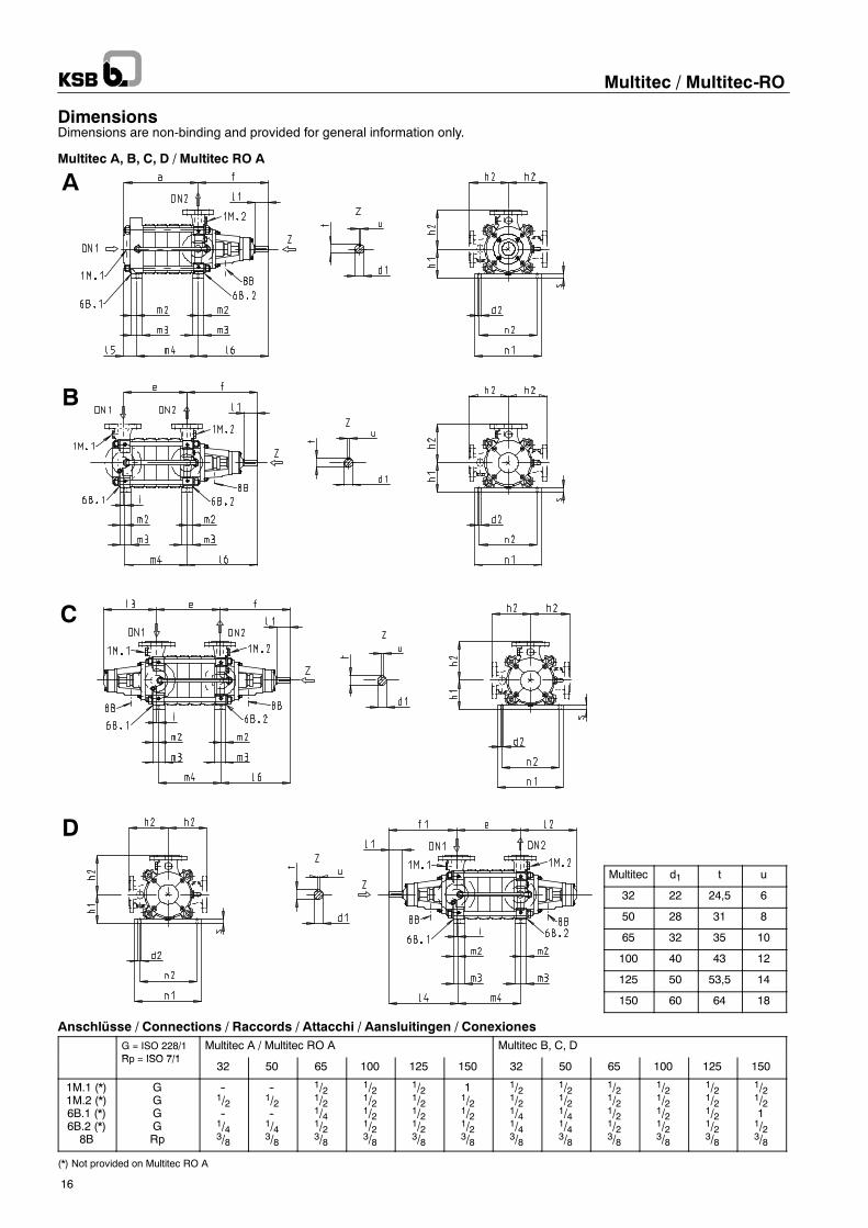
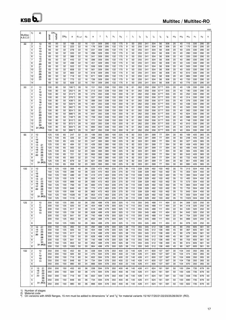
DimensionsDimensions are non-binding and provided for general information only.
Multitec A, B, C, D / Multitec RO A
Multitec d1 t u
32 22 24,5 6
50 28 31 8
65 32 35 10
100 40 43 12
125 50 53,5 14
150 60 64 18
Anschlüsse / Connections / Raccords / Attacchi / Aansluitingen / ConexionesG = ISO 228/1R ISO 7/1
Multitec A / Multitec RO A Multitec B, C, DRp = ISO 7/1
32 50 65 100 125 150 32 50 65 100 125 150
1M.1 (*)1M.2 (*)6B.1 (*)6B.2 (*)8B
GGGGRp
--1/2--1/43/8
--1/2--1/43/8
1/21/21/41/23/8
1/21/21/21/23/8
1/21/21/21/23/8
11/21/21/23/8
1/21/21/41/43/8
1/21/21/41/43/8
1/21/21/21/23/8
1/21/21/21/23/8
1/21/21/21/23/8
1/21/211/23/8
(*) Not provided on Multitec RO A
axial
radial
Multitec / Multitec-RO
17
mm
M ltit1) 2) DN1
MultitecA,B,C,D
1) 2)
DN2 a d1 k7 d2 e f f1 h1 h2 i l1 l2 l3 l4 l5 l6 m2 m3 m4 n1 n2 s
32 2 10 65 50 32 168 22 16 121 309 295 132 175 9 50 255 241 304 56 306 20 40 115 330 290 20323
101112
65 50 32 223 22 16 176 309 295 132 175 9 50 255 241 304 56 306 20 40 170 330 290 204 12
1365 50 32 278 22 16 231 309 295 132 175 9 50 255 241 304 56 306 20 40 225 330 290 20
51314 65 50 32 333 22 16 286 309 295 132 175 9 50 255 241 304 56 306 20 40 280 330 290 20
6141516
65 50 32 388 22 16 341 309 295 132 175 9 50 255 241 304 56 306 20 40 335 330 290 207
151617
65 50 32 443 22 16 396 309 295 132 175 9 50 255 241 304 56 306 20 40 390 330 290 208
1720 65 50 32 498 22 16 451 309 295 132 175 9 50 255 241 304 56 306 20 40 445 330 290 20
9202122
65 50 32 553 22 16 506 309 295 132 175 9 50 255 241 304 56 306 20 40 500 330 290 2010
212223
65 50 32 608 22 16 561 309 295 132 175 9 50 255 241 304 56 306 20 40 555 330 290 2011 23
2565 50 32 663 22 16 616 309 295 132 175 9 50 255 241 304 56 306 20 40 610 330 290 20
122526 65 50 32 718 22 16 671 309 295 132 175 9 50 255 241 304 56 306 20 40 665 330 290 20
132630 65 50 32 773 22 16 726 309 295 132 175 9 50 255 241 304 56 306 20 40 720 330 290 20
14 65 50 32 828 22 16 781 309 295 132 175 9 50 255 241 304 56 306 20 40 775 330 290 20
50 2 1011
100 80 50 190 *) 28 16 151 350 338 150 200 18 61 262 250 356 57 *) 355 20 40 128 330 290 20
3 1112
100 80 50 252 *) 28 16 213 350 338 150 200 18 61 262 250 356 57 *) 355 20 40 190 330 290 204
1213 100 80 50 314 *) 28 16 275 350 338 150 200 18 61 262 250 356 57 *) 355 20 40 252 330 290 20
5131415
100 80 50 376 *) 28 16 337 350 338 150 200 18 61 262 250 356 57 *) 355 20 40 314 330 290 206 15
16100 80 50 438 *) 28 16 399 350 338 150 200 18 61 262 250 356 57 *) 355 20 40 376 330 290 20
71617 100 80 50 500 *) 28 16 461 350 338 150 200 18 61 262 250 356 57 *) 355 20 40 438 330 290 20
81720 100 80 50 562 *) 28 16 523 350 338 150 200 18 61 262 250 356 57 *) 355 20 40 500 330 290 20
9202122
100 80 50 624 *) 28 16 585 350 338 150 200 18 61 262 250 356 57 *) 355 20 40 562 330 290 2010 22
23100 80 50 686 *) 28 16 647 350 338 150 200 18 61 262 250 356 57 *) 355 20 40 624 330 290 20
112325 100 80 50 748 *) 28 16 709 350 338 150 200 18 61 262 250 356 57 *) 355 20 40 686 330 290 20
12252627
100 80 50 810 *) 28 16 771 350 338 150 200 18 61 262 250 356 57 *) 355 20 40 748 330 290 2013 27
30100 80 50 872 *) 28 16 833 350 338 150 200 18 61 262 250 356 57 *) 355 20 40 810 330 290 20
1430
31 (RO) 100 80 50 934 *) 28 16 895 350 338 150 200 18 61 262 250 356 57 *) 355 20 40 872 330 290 2015
31 (RO)100 80 50 996 *) 28 16 957 350 338 150 200 18 61 262 250 356 57 *) 355 20 40 934 330 290 20
65 2 1011
125 100 65 247 32 20 189 393 380 190 225 18 82 303 291 399 77 394 30 60 169 405 365 25653
101112
125 100 65 326 32 20 268 393 380 190 225 18 82 303 291 399 77 394 30 60 248 405 365 254
1213 125 100 65 405 32 20 347 393 380 190 225 18 82 303 291 399 77 394 30 60 327 405 365 25
51314 21 125 100 65 484 32 20 426 393 380 190 225 18 82 303 291 399 77 394 30 60 406 405 365 25
614 2115 2216 23
125 100 65 563 32 20 505 393 380 190 225 18 82 303 291 399 77 394 30 60 485 405 365 257 16 23
17 25125 100 65 642 32 20 584 393 380 190 225 18 82 303 291 399 77 394 30 60 564 405 365 25
817 2520 26 125 100 65 721 32 20 663 393 380 190 225 18 82 303 291 399 77 394 30 60 643 405 365 25
920 26
2730
125 100 65 800 32 20 742 393 380 190 225 18 82 303 291 399 77 394 30 60 722 405 365 2510 30
31 (RO)125 100 65 879 32 20 821 393 380 190 225 18 82 303 291 399 77 394 30 60 801 405 365 25
1131 (RO)
125 100 65 958 32 20 900 393 380 190 225 18 82 303 291 399 77 394 30 60 880 405 365 25
100 2 1011
150 125 100 306 40 26 233 472 463 235 275 30 110 339 329 492 103 462 35 70 213 504 450 301003
101112
150 125 100 396 40 26 323 472 463 235 275 30 110 339 329 492 103 462 35 70 303 504 450 304
1213 150 125 100 486 40 26 413 472 463 235 275 30 110 339 329 492 103 462 35 70 393 504 450 30
51314 21 150 125 100 576 40 26 503 472 463 235 275 30 110 339 329 492 103 462 35 70 483 504 450 30
614 2115 2216 23
150 125 100 666 40 26 593 472 463 235 275 30 110 339 329 492 103 462 35 70 573 504 450 307 16 23
17 25150 125 100 756 40 26 683 472 463 235 275 30 110 339 329 492 103 462 35 70 663 504 450 30
817 2520 26 150 125 100 846 40 26 773 472 463 235 275 30 110 339 329 492 103 462 35 70 753 504 450 30
920 26
2730
150 125 100 936 40 26 863 472 463 235 275 30 110 339 329 492 103 462 35 70 843 504 450 3010 30
31 (RO)150 125 100 1026 40 26 953 472 463 235 275 30 110 339 329 492 103 462 35 70 933 504 450 30
1131 (RO)
150 125 100 1116 40 26 1043 472 463 235 275 30 110 339 329 492 103 462 35 70 1023 504 450 30
125 2 1011
200 150 125 393 50 26 292 488 478 300 325 10 110 355 345 488 111 464 22 94 306 320 250 301253
101112
200 150 125 505 50 26 404 488 478 300 325 10 110 355 345 488 111 464 22 94 418 320 250 304
1213 200 150 125 617 50 26 516 488 478 300 325 10 110 355 345 488 111 464 22 94 530 320 250 30
51314 200 150 125 729 50 26 628 488 478 300 325 10 110 355 345 488 111 464 22 94 642 320 250 30
614
200 150 125 841 50 26 740 488 478 300 325 10 110 355 345 488 111 464 22 94 754 320 250 307 200 150 125 953 50 26 852 488 478 300 325 10 110 355 345 488 111 464 22 94 866 320 250 30
8 200 150 125 1065 50 26 964 488 478 300 325 10 110 355 345 488 111 464 22 94 978 320 250 30
2 15 21 200 150 125 393 50 30 292 488 478 300 325 38 110 355 345 512 136 490 45 90 255 605 561 503
15 2116 2217 23
200 150 125 505 50 30 404 488 478 300 325 38 110 355 345 512 136 490 45 90 367 605 561 504 17 23
20 25200 150 125 617 50 30 516 488 478 300 325 38 110 355 345 512 136 490 45 90 479 605 561 50
520 25
26 200 150 125 729 50 30 628 488 478 300 325 38 110 355 345 512 136 490 45 90 591 605 561 506
262730
200 150 125 841 50 30 740 488 478 300 325 38 110 355 345 512 136 490 45 90 703 605 561 507 30
31 (RO)200 150 125 953 50 30 852 488 478 300 325 38 110 355 345 512 136 490 45 90 815 605 561 50
831 (RO)
200 150 125 1065 50 30 964 488 478 300 325 38 110 355 345 512 136 490 45 90 927 605 561 50
150 2 1011
250 200 150 452 60 34 338 594 578 350 400 22 140 426 411 600 137 567 30 104 342 350 265 301503
101112
250 200 150 584 60 34 470 594 578 350 400 22 140 426 411 600 137 567 30 104 474 350 265 304
1213 250 200 150 716 60 34 602 594 578 350 400 22 140 426 411 600 137 567 30 104 606 350 265 30
51314 250 200 150 848 60 34 734 594 578 350 400 22 140 426 411 600 137 567 30 104 738 350 265 30
614
250 200 150 980 60 34 866 594 578 350 400 22 140 426 411 600 137 567 30 104 870 350 265 30
2 15 2116 22
250 200 150 452 60 36 338 594 578 350 400 46 140 426 411 624 161 591 50 100 294 735 679 50
3 16 2217 23
250 200 150 584 60 36 470 594 578 350 400 46 140 426 411 624 161 591 50 100 426 735 679 50
417 2320 25
26250 200 150 716 60 36 602 594 578 350 400 46 140 426 411 624 161 591 50 100 558 735 679 50
52630
31 (RO)250 200 150 848 60 36 734 594 578 350 400 46 140 426 411 624 161 591 50 100 690 735 679 50
6 31 (RO) 250 200 150 980 60 36 866 594 578 350 400 46 140 426 411 624 161 591 50 100 822 735 679 50
1) Number of stages2) Material code*) On versions with ANSI flanges, 15 mm must be added to dimensions ”a” and ”l5” for material variants 15/16/17/20/21/22/23/25/26/30/31 (RO).
E
F
Multitec / Multitec-RO
18
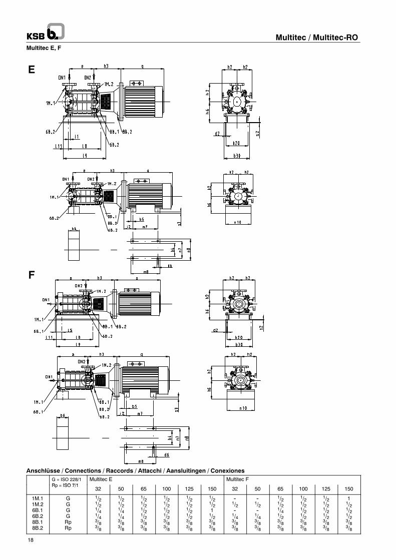
Multitec E, F
Anschlüsse / Connections / Raccords / Attacchi / Aansluitingen / ConexionesG = ISO 228/1Rp ISO 7/1
Multitec E Multitec FRp = ISO 7/1
32 50 65 100 125 150 32 50 65 100 125 150
1M.11M.26B.16B.28B.18B.2
GGGGRpRp
1/21/21/41/43/83/8
1/21/21/41/43/83/8
1/21/21/21/23/83/8
1/21/21/21/23/83/8
1/21/21/21/23/83/8
1/21/211/23/83/8
--1/2--1/43/83/8
--1/2--1/43/83/8
1/21/21/41/23/83/8
1/21/21/21/23/83/8
1/21/21/21/23/83/8
11/21/21/23/83/8
axial
radial
Multitec / Multitec-RO
19
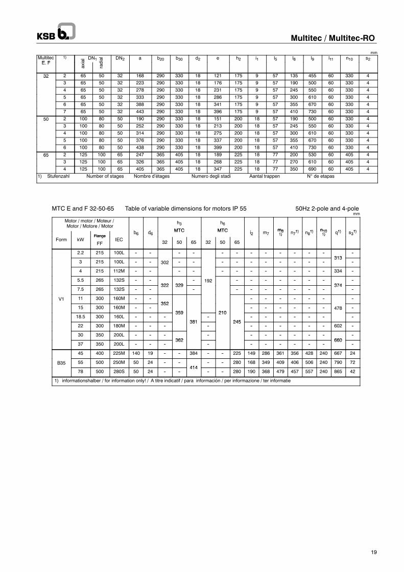
mmMultitecE F
1) DN1 DN2 a b20 b30 d2 e h2 i1 l5 l8 l9 l11 n10 s2E. F
32 2 65 50 32 168 290 330 18 121 175 9 57 135 455 60 330 432
3 65 50 32 223 290 330 18 176 175 9 57 190 500 60 330 4
4 65 50 32 278 290 330 18 231 175 9 57 245 550 60 330 4
5 65 50 32 333 290 330 18 286 175 9 57 300 610 60 330 4
6 65 50 32 388 290 330 18 341 175 9 57 355 670 60 330 4
7 65 50 32 443 290 330 18 396 175 9 57 410 730 60 330 4
50 2 100 80 50 190 290 330 18 151 200 18 57 190 500 60 330 450
3 100 80 50 252 290 330 18 213 200 18 57 245 550 60 330 4
4 100 80 50 314 290 330 18 275 200 18 57 300 610 60 330 4
5 100 80 50 376 290 330 18 337 200 18 57 355 670 60 330 4
6 100 80 50 438 290 330 18 399 200 18 57 410 730 60 330 4
65 2 125 100 65 247 365 405 18 189 225 18 77 200 530 60 405 465
3 125 100 65 326 365 405 18 268 225 18 77 270 610 60 405 4
4 125 100 65 405 365 405 18 347 225 18 77 350 690 60 405 4
1) Stufenzahl Number of stages Nombre d’étages Numero degli stadi Aantal trappen N° de etapas
MTC E and F 32-50-65 Table of variable dimensions for motors IP 55 50Hz 2-pole and 4-polemm
Motor / motor / Moteur /Motor / Motore / Motor
b d
h3
MTC
h6
MTC i m8 1) 1) n10 1) 1)Flange
b6 d6MTC MTC i2 m7
m81) n71) n81)
n101) q1) s31)
Form kWFlange
FFIEC
6 6
32 50 65 32 50 65
2 7 1) 7 8 1) q 3
2.2 215 100L -- -- -- -- -- -- -- -- -- -- -- --313
--
3 215 100L -- -- 302 -- -- -- -- -- -- -- -- -- --313
--
4 215 112M -- -- -- -- -- -- -- -- -- -- -- -- 334 --
5.5 265 132S -- --322 329
-- 192 -- -- -- -- -- -- --374
--
7.5 265 132S -- --322 329
-- -- -- -- -- -- -- --374
--
V1 11 300 160M -- --352
-- -- -- -- -- -- --
15 300 160M -- --352
359 210-- -- -- -- -- -- 478 --
18.5 300 160L -- -- --359
381--
210
245-- -- -- -- -- -- --
22 300 180M -- -- --381
--245
-- -- -- -- -- -- 602 --
30 350 200L -- -- --362
-- -- -- -- -- -- --660
--
37 350 200L -- -- --362
-- -- -- -- -- -- --660
--
45 400 225M 140 19 -- -- 384 -- -- 225 149 286 361 356 428 240 667 24
B35 55 500 250M 50 24 -- --414
-- -- 280 168 349 409 406 506 240 790 72
78 500 280S 50 24 -- --414
-- -- 280 190 368 479 457 557 240 865 42
1) informationshalber / for information only! / A titre indicatif / para información / per informazione / ter informatie
v
Multitec / Multitec-RO
20
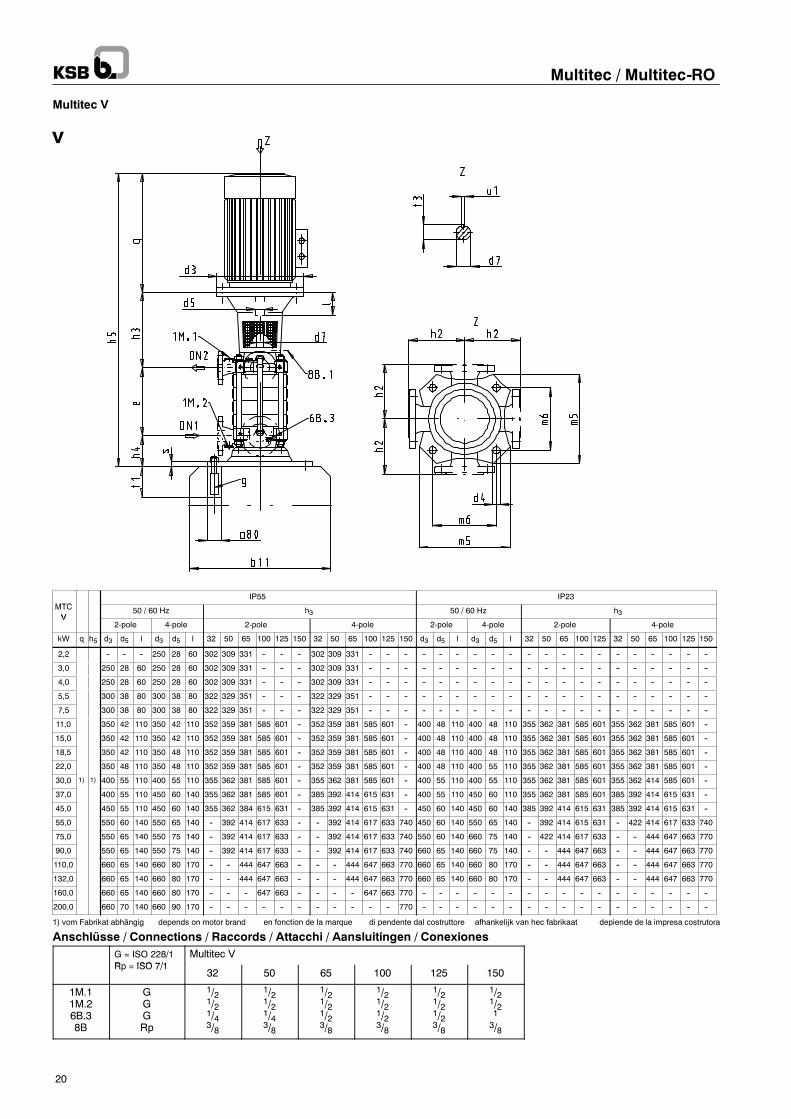
Multitec V
MTCIP55 IP23
MTCV
50 / 60 Hz h3 50 / 60 Hz h3V
2-pole 4-pole 2-pole 4-pole 2-pole 4-pole 2-pole 4-pole
kW q h5 d3 d5 l d3 d5 l 32 50 65 100 125 150 32 50 65 100 125 150 d3 d5 l d3 d5 l 32 50 65 100 125 32 50 65 100 125 150
2,2 -- -- -- 250 28 60 302 309 331 -- -- -- 302 309 331 -- -- -- -- -- -- -- -- -- -- -- -- -- -- -- -- -- -- -- --
3,0 250 28 60 250 28 60 302 309 331 -- -- -- 302 309 331 -- -- -- -- -- -- -- -- -- -- -- -- -- -- -- -- -- -- -- --
4,0 250 28 60 250 28 60 302 309 331 -- -- -- 302 309 331 -- -- -- -- -- -- -- -- -- -- -- -- -- -- -- -- -- -- -- --
5,5 300 38 80 300 38 80 322 329 351 -- -- -- 322 329 351 -- -- -- -- -- -- -- -- -- -- -- -- -- -- -- -- -- -- -- --
7,5 300 38 80 300 38 80 322 329 351 -- -- -- 322 329 351 -- -- -- -- -- -- -- -- -- -- -- -- -- -- -- -- -- -- -- --
11,0 350 42 110 350 42 110 352 359 381 585 601 -- 352 359 381 585 601 -- 400 48 110 400 48 110 355 362 381 585 601 355 362 381 585 601 --
15,0 350 42 110 350 42 110 352 359 381 585 601 -- 352 359 381 585 601 -- 400 48 110 400 48 110 355 362 381 585 601 355 362 381 585 601 --
18,5 350 42 110 350 48 110 352 359 381 585 601 -- 352 359 381 585 601 -- 400 48 110 400 48 110 355 362 381 585 601 355 362 381 585 601 --
22,0 350 48 110 350 48 110 352 359 381 585 601 -- 352 359 381 585 601 -- 400 48 110 400 55 110 355 362 381 585 601 355 362 381 585 601 --
30,0 1) 1) 400 55 110 400 55 110 355 362 381 585 601 -- 355 362 381 585 601 -- 400 55 110 400 55 110 355 362 381 585 601 355 362 414 585 601 --
37,0 400 55 110 450 60 140 355 362 381 585 601 -- 385 392 414 615 631 -- 400 55 110 450 60 110 355 362 381 585 601 385 392 414 615 631 --
45,0 450 55 110 450 60 140 355 362 384 615 631 -- 385 392 414 615 631 -- 450 60 140 450 60 140 385 392 414 615 631 385 392 414 615 631 --
55,0 550 60 140 550 65 140 -- 392 414 617 633 -- -- 392 414 617 633 740 450 60 140 550 65 140 -- 392 414 615 631 -- 422 414 617 633 740
75,0 550 65 140 550 75 140 -- 392 414 617 633 -- -- 392 414 617 633 740 550 60 140 660 75 140 -- 422 414 617 633 -- -- 444 647 663 770
90,0 550 65 140 550 75 140 -- 392 414 617 633 -- -- 392 414 617 633 740 660 65 140 660 75 140 -- -- 444 647 663 -- -- 444 647 663 770
110,0 660 65 140 660 80 170 -- -- 444 647 663 -- -- -- 444 647 663 770 660 65 140 660 80 170 -- -- 444 647 663 -- -- 444 647 663 770
132,0 660 65 140 660 80 170 -- -- 444 647 663 -- -- -- 444 647 663 770 660 65 140 660 80 170 -- -- 444 647 663 -- -- 444 647 663 770
160,0 660 65 140 660 80 170 -- -- -- 647 663 -- -- -- -- 647 663 770 -- -- -- -- -- -- -- -- -- -- -- -- -- -- -- -- --
200,0 660 70 140 660 90 170 -- -- -- -- -- -- -- -- -- -- -- 770 -- -- -- -- -- -- -- -- -- -- -- -- -- -- -- -- --
1) vom Fabrikat abhängig depends on motor brand en fonction de la marque di pendente dal costruttore afhankelijk van hec fabrikaat depiende de la impresa costrutora
Anschlüsse / Connections / Raccords / Attacchi / Aansluitingen / ConexionesG = ISO 228/1R ISO 7/1
Multitec VRp = ISO 7/1
32 50 65 100 125 150
1M.11M.26B.38B
GGGRp
1/21/21/43/8
1/21/21/43/8
1/21/21/23/8
1/21/21/23/8
1/21/21/23/8
1/21/213/8
Multitec / Multitec-RO
21
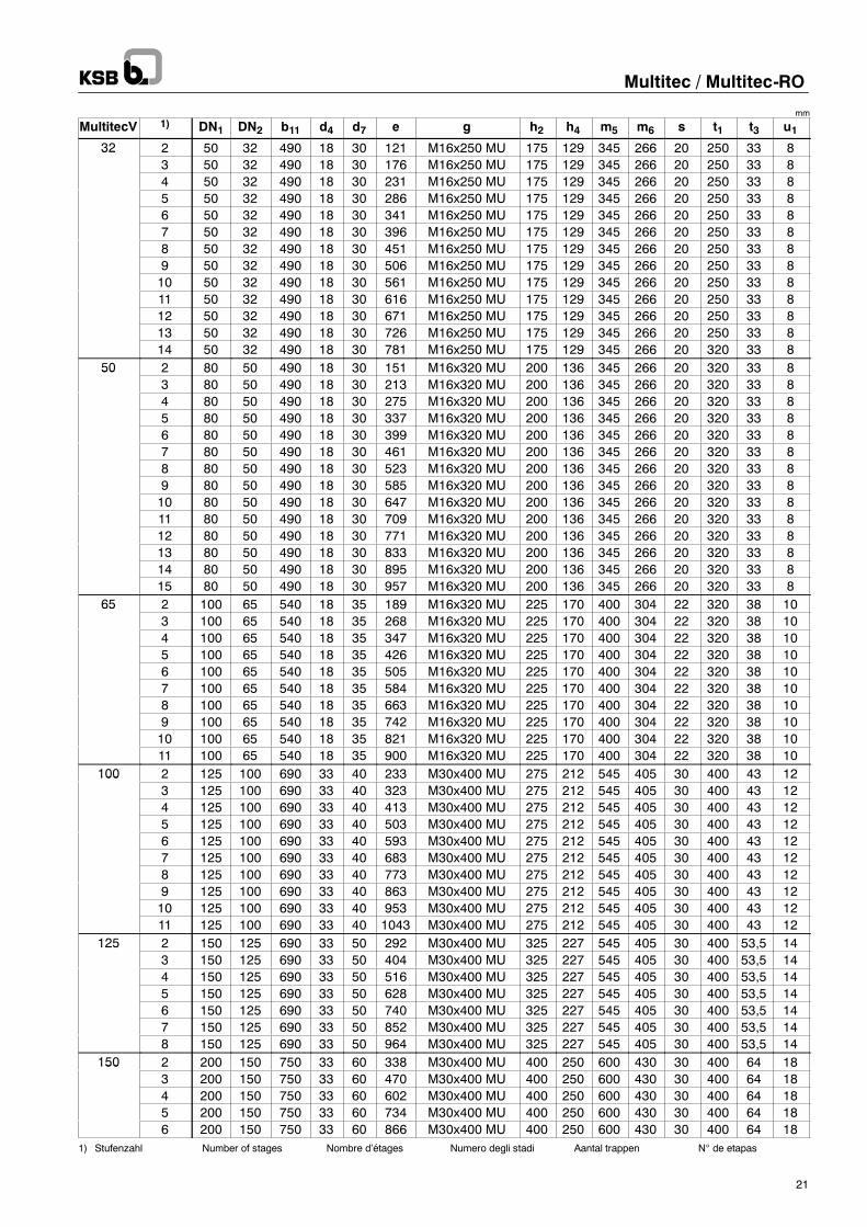
mm
MultitecV 1) DN1 DN2 b11 d4 d7 e g h2 h4 m5 m6 s t1 t3 u132 2 50 32 490 18 30 121 M16x250 MU 175 129 345 266 20 250 33 832
3 50 32 490 18 30 176 M16x250 MU 175 129 345 266 20 250 33 84 50 32 490 18 30 231 M16x250 MU 175 129 345 266 20 250 33 85 50 32 490 18 30 286 M16x250 MU 175 129 345 266 20 250 33 86 50 32 490 18 30 341 M16x250 MU 175 129 345 266 20 250 33 87 50 32 490 18 30 396 M16x250 MU 175 129 345 266 20 250 33 88 50 32 490 18 30 451 M16x250 MU 175 129 345 266 20 250 33 89 50 32 490 18 30 506 M16x250 MU 175 129 345 266 20 250 33 810 50 32 490 18 30 561 M16x250 MU 175 129 345 266 20 250 33 811 50 32 490 18 30 616 M16x250 MU 175 129 345 266 20 250 33 812 50 32 490 18 30 671 M16x250 MU 175 129 345 266 20 250 33 813 50 32 490 18 30 726 M16x250 MU 175 129 345 266 20 250 33 814 50 32 490 18 30 781 M16x250 MU 175 129 345 266 20 320 33 8
50 2 80 50 490 18 30 151 M16x320 MU 200 136 345 266 20 320 33 8503 80 50 490 18 30 213 M16x320 MU 200 136 345 266 20 320 33 84 80 50 490 18 30 275 M16x320 MU 200 136 345 266 20 320 33 85 80 50 490 18 30 337 M16x320 MU 200 136 345 266 20 320 33 86 80 50 490 18 30 399 M16x320 MU 200 136 345 266 20 320 33 87 80 50 490 18 30 461 M16x320 MU 200 136 345 266 20 320 33 88 80 50 490 18 30 523 M16x320 MU 200 136 345 266 20 320 33 89 80 50 490 18 30 585 M16x320 MU 200 136 345 266 20 320 33 810 80 50 490 18 30 647 M16x320 MU 200 136 345 266 20 320 33 811 80 50 490 18 30 709 M16x320 MU 200 136 345 266 20 320 33 812 80 50 490 18 30 771 M16x320 MU 200 136 345 266 20 320 33 813 80 50 490 18 30 833 M16x320 MU 200 136 345 266 20 320 33 814 80 50 490 18 30 895 M16x320 MU 200 136 345 266 20 320 33 815 80 50 490 18 30 957 M16x320 MU 200 136 345 266 20 320 33 8
65 2 100 65 540 18 35 189 M16x320 MU 225 170 400 304 22 320 38 10653 100 65 540 18 35 268 M16x320 MU 225 170 400 304 22 320 38 104 100 65 540 18 35 347 M16x320 MU 225 170 400 304 22 320 38 105 100 65 540 18 35 426 M16x320 MU 225 170 400 304 22 320 38 106 100 65 540 18 35 505 M16x320 MU 225 170 400 304 22 320 38 107 100 65 540 18 35 584 M16x320 MU 225 170 400 304 22 320 38 108 100 65 540 18 35 663 M16x320 MU 225 170 400 304 22 320 38 109 100 65 540 18 35 742 M16x320 MU 225 170 400 304 22 320 38 1010 100 65 540 18 35 821 M16x320 MU 225 170 400 304 22 320 38 1011 100 65 540 18 35 900 M16x320 MU 225 170 400 304 22 320 38 10
100 2 125 100 690 33 40 233 M30x400 MU 275 212 545 405 30 400 43 121003 125 100 690 33 40 323 M30x400 MU 275 212 545 405 30 400 43 124 125 100 690 33 40 413 M30x400 MU 275 212 545 405 30 400 43 125 125 100 690 33 40 503 M30x400 MU 275 212 545 405 30 400 43 126 125 100 690 33 40 593 M30x400 MU 275 212 545 405 30 400 43 127 125 100 690 33 40 683 M30x400 MU 275 212 545 405 30 400 43 128 125 100 690 33 40 773 M30x400 MU 275 212 545 405 30 400 43 129 125 100 690 33 40 863 M30x400 MU 275 212 545 405 30 400 43 1210 125 100 690 33 40 953 M30x400 MU 275 212 545 405 30 400 43 1211 125 100 690 33 40 1043 M30x400 MU 275 212 545 405 30 400 43 12
125 2 150 125 690 33 50 292 M30x400 MU 325 227 545 405 30 400 53,5 141253 150 125 690 33 50 404 M30x400 MU 325 227 545 405 30 400 53,5 144 150 125 690 33 50 516 M30x400 MU 325 227 545 405 30 400 53,5 145 150 125 690 33 50 628 M30x400 MU 325 227 545 405 30 400 53,5 146 150 125 690 33 50 740 M30x400 MU 325 227 545 405 30 400 53,5 147 150 125 690 33 50 852 M30x400 MU 325 227 545 405 30 400 53,5 148 150 125 690 33 50 964 M30x400 MU 325 227 545 405 30 400 53,5 14
150 2 200 150 750 33 60 338 M30x400 MU 400 250 600 430 30 400 64 181503 200 150 750 33 60 470 M30x400 MU 400 250 600 430 30 400 64 184 200 150 750 33 60 602 M30x400 MU 400 250 600 430 30 400 64 185 200 150 750 33 60 734 M30x400 MU 400 250 600 430 30 400 64 186 200 150 750 33 60 866 M30x400 MU 400 250 600 430 30 400 64 18
1) Stufenzahl Number of stages Nombre d’étages Numero degli stadi Aantal trappen N° de etapas

Multitec / Multitec-RO
22

Multitec / Multitec-RO
23
1777.5/8-10
01.12.2010
Subjecttotechnicalm
odificationwithoutpriornotice.
KSB AktiengesellschaftP.O. Box 1361 • 91253 Pegnitz • Bahnhofplatz 1 • 91257 Pegnitz (Germany)Tel. +49 9241 71-0 • Fax +49 9241 71-1793www.ksb.com
Multitec / Multitec-RO
Related Documents