Copyright © 2007 by the Association for Computing Machinery, Inc. Permission to make digital or hard copies of part or all of this work for personal or classroom use is granted without fee provided that copies are not made or distributed for commercial advantage and that copies bear this notice and the full citation on the first page. Copyrights for components of this work owned by others than ACM must be honored. Abstracting with credit is permitted. To copy otherwise, to republish, to post on servers, or to redistribute to lists, requires prior specific permission and/or a fee. Request permissions from Permissions Dept, ACM Inc., fax +1 (212) 869-0481 or e-mail [email protected] . GRAPHITE 2007, Perth, Western Australia, December 1–4, 2007. © 2007 ACM 978-1-59593-912-8/07/0012 $5.00 Multiresolution Geometric Details on Subdivision Surfaces Przemyslaw Musialski * Bauhaus-University Weimar VRVis Research Center Robert F. Tobler † Stefan Maierhofer ‡ VRVis Research Center Charles A. W ¨ uthrich § Bauhaus-University Weimar Figure 1: A patch with calf leather pattern. From left to right different frequency bands of the underling displacement map has been enhanced on different subdivision resolutions. Last two patches on the right-hand side use low frequencies from a different sample. Abstract Subdivision surfaces are methods for creating smooth surfaces out of coarse polyhedral meshes. Due to their recursive nature they are ideally suited for adding geometric detail on different resolutions. When modeling real-world surfaces it is possible to extract the fine surface details from a material and apply these on dense meshes in the form of vertex displacements. Material characteristics are a mixture of features at different scales, which can be recovered by a frequency decomposition of an input height map. Applying these sub-bands as displacement in a recursive multiresolution fashion allows the ability to influence or mix details obtained from one or more sources. This paper presents a method for computing multiresolution dis- placed subdivision surfaces on the GPU that performs in real-time and provides an interactive control over the obtained results. CR Categories: I.3.5 [Computer Graphics]: Computational Ge- ometry and Object Modeling—Boundary representations Keywords: subdivision surfaces, displacement mapping, multires- olution, real-time rendering 1 Introduction Real-life surfaces are very rarely completely smooth. Most natu- ral surfaces exhibit many levels of roughness and coarseness, es- pecially if they are inspected in detail. Therefore many computer- generated models of real-life objects which are rendered with per- fectly smooth surfaces appear sterile and artificial. Over the years computer graphics has developed several approaches to avoid this * [email protected] † [email protected] ‡ [email protected] § [email protected] problem. One of the first methods in this category was bump map- ping [Blinn 1978], and its improved descendant, parallax mapping [Oliveira et al. 2000]. Both of these methods do not influence the actual geometry of the underlying model, but change its rendered appearance. On the other hand, a whole area of computer graphics research deals with subdivision surfaces, a powerful tool for representing objects with smooth surfaces. Due to their nature, subdivision surfaces can be either rendered using successively finer approximations or eval- uated exactly for selected surface parts. Since subdivision surfaces can be generated from base geometry of any topology, they are very easy to handle in the modeling process, and have therefore become the tool of choice in applications which aim at highly realistic ap- pearance of smooth models. In this paper we present a method to apply multiresolution geo- metric detail on subdivision surfaces in real-time. The additional surface detail can be generated artificially, handcrafted or based on an analysis of a real surface sample. During the rendering process, it can be applied automatically in form of multi-band displacement maps on different subdivision levels of the underlying surface. As a basis for our work, the next section presents an overview of subdivision surfaces and the displacement approach as well as a brief explanation of sub-band decomposition. The novelty of our work lies in the combination of these techniques and its implemen- tation on graphics hardware, which are explained in sections 3 and 4. Sections 5 and 6 present our results and conclude the work. 2 Related Work 2.1 Subdivision Surfaces Mesh subdivision is a technique for generating smooth surfaces that has been introduced quite some time ago [Catmull and Clark 1978; Doo and Sabin 1978]. The standard subdivision process starts out with a mesh M (0) composed of vertices, edges, and faces that serves as the base for a sequence of refined meshes M (0) ,M (1) ,M (2) , ..., M (k) which converges to a limit surface for k →∞. This surface, also called the subdivision surface, possesses certain continuity properties (i.e. C 2 ). For a long time the theoretical foundation of the subdivision pro- cess was not as thoroughly developed as for other modeling tech- niques such as B-splines and the more general NURBS, and thus it 211

Welcome message from author
This document is posted to help you gain knowledge. Please leave a comment to let me know what you think about it! Share it to your friends and learn new things together.
Transcript

Copyright © 2007 by the Association for Computing Machinery, Inc. Permission to make digital or hard copies of part or all of this work for personal or classroom use is granted without fee provided that copies are not made or distributed for commercial advantage and that copies bear this notice and the full citation on the first page. Copyrights for components of this work owned by others than ACM must be honored. Abstracting with credit is permitted. To copy otherwise, to republish, to post on servers, or to redistribute to lists, requires prior specific permission and/or a fee. Request permissions from Permissions Dept, ACM Inc., fax +1 (212) 869-0481 or e-mail [email protected]. GRAPHITE 2007, Perth, Western Australia, December 1–4, 2007. © 2007 ACM 978-1-59593-912-8/07/0012 $5.00
Multiresolution Geometric Details on Subdivision Surfaces
Przemyslaw Musialski∗
Bauhaus-University WeimarVRVis Research Center
Robert F. Tobler†
Stefan Maierhofer‡
VRVis Research Center
Charles A. Wuthrich§
Bauhaus-University Weimar
Figure 1: A patch with calf leather pattern. From left to right different frequency bands of the underling displacement map has been enhancedon different subdivision resolutions. Last two patches on the right-hand side use low frequencies from a different sample.
Abstract
Subdivision surfaces are methods for creating smooth surfaces outof coarse polyhedral meshes. Due to their recursive nature they areideally suited for adding geometric detail on different resolutions.When modeling real-world surfaces it is possible to extract the finesurface details from a material and apply these on dense meshesin the form of vertex displacements. Material characteristics are amixture of features at different scales, which can be recovered bya frequency decomposition of an input height map. Applying thesesub-bands as displacement in a recursive multiresolution fashionallows the ability to influence or mix details obtained from one ormore sources.
This paper presents a method for computing multiresolution dis-placed subdivision surfaces on the GPU that performs in real-timeand provides an interactive control over the obtained results.
CR Categories: I.3.5 [Computer Graphics]: Computational Ge-ometry and Object Modeling—Boundary representations
Keywords: subdivision surfaces, displacement mapping, multires-olution, real-time rendering
1 Introduction
Real-life surfaces are very rarely completely smooth. Most natu-ral surfaces exhibit many levels of roughness and coarseness, es-pecially if they are inspected in detail. Therefore many computer-generated models of real-life objects which are rendered with per-fectly smooth surfaces appear sterile and artificial. Over the yearscomputer graphics has developed several approaches to avoid this
∗[email protected]†[email protected]‡[email protected]§[email protected]
problem. One of the first methods in this category was bump map-ping [Blinn 1978], and its improved descendant, parallax mapping[Oliveira et al. 2000]. Both of these methods do not influence theactual geometry of the underlying model, but change its renderedappearance.
On the other hand, a whole area of computer graphics research dealswith subdivision surfaces, a powerful tool for representing objectswith smooth surfaces. Due to their nature, subdivision surfaces canbe either rendered using successively finer approximations or eval-uated exactly for selected surface parts. Since subdivision surfacescan be generated from base geometry of any topology, they are veryeasy to handle in the modeling process, and have therefore becomethe tool of choice in applications which aim at highly realistic ap-pearance of smooth models.
In this paper we present a method to apply multiresolution geo-metric detail on subdivision surfaces in real-time. The additionalsurface detail can be generated artificially, handcrafted or based onan analysis of a real surface sample. During the rendering process,it can be applied automatically in form of multi-band displacementmaps on different subdivision levels of the underlying surface.
As a basis for our work, the next section presents an overview ofsubdivision surfaces and the displacement approach as well as abrief explanation of sub-band decomposition. The novelty of ourwork lies in the combination of these techniques and its implemen-tation on graphics hardware, which are explained in sections 3 and4. Sections 5 and 6 present our results and conclude the work.
2 Related Work
2.1 Subdivision Surfaces
Mesh subdivision is a technique for generating smooth surfacesthat has been introduced quite some time ago [Catmull and Clark1978; Doo and Sabin 1978]. The standard subdivision processstarts out with a mesh M (0) composed of vertices, edges, andfaces that serves as the base for a sequence of refined meshesM (0), M (1), M (2), ..., M (k) which converges to a limit surface fork →∞. This surface, also called the subdivision surface, possessescertain continuity properties (i.e. C2).
For a long time the theoretical foundation of the subdivision pro-cess was not as thoroughly developed as for other modeling tech-niques such as B-splines and the more general NURBS, and thus it
211

took a while for subdivision methods to become widely adopted. Inthe last decade this has been rectified by the introduction of meth-ods to analyze and evaluate subdivision surfaces at any point [Reif1995; Stam 1998], a method for extending subdivision surfaces toapproximate NURBS [Sederberg et al. 1998], the addition of con-trolled boundaries [Biermann et al. 2000], and a method to deriveNURBS patches from subdivision surfaces [Peters 2000]. A num-ber of other extensions to subdivision surfaces [DeRose et al. 1998;Lee et al. 2000; Ying and Zorin 2001; Boier-Martin and Zorin 2004]have established them as the modeling tool of choice for generatingtopologically complex, smooth surfaces.
2.1.1 Evaluation Approaches of Subdivision Surfaces
Many researchers have focused on the problem of fast evaluationand real-time rendering of subdivision surfaces. In general, besidesthe exact evaluation [Halstead et al. 1993; Stam 1998; Zorin andKristjansson 2002] three major strategies can be distinguished: (1)forward differencing, [Pulli and Segal 1996; Bischoff et al. 2000],(2) precomputed and tabulated basis functions [Bolz and Schroder2002; Bolz and Schroder 2003] and the most known and widelyused (3) recursive evaluation [DeRose et al. 1998; Biermann et al.2000]. In our work we use the latter one, since it is more flex-ible than precomputed basis functions and more stable, than thenumeric method of forward differencing. In addition to that, it isnaturally suited to introduce variations at each recursive evaluationlevel. One disadvantage of this approach is the exponential growthof the geometric data, where usually only a small part is visible at aparticular moment.
In order to reduce the enormous space complexity of the subdivi-sion process, Pulli and Segal have introduced a strategy for eval-uating and rendering which they called sliding window [Pulli andSegal 1996]. This technique uses a fixed memory portion whichcontains only a (small) piece of the actual surface. This piecebecomes evaluated with the forward differencing method and ren-dered. After that the data is discarded, and a next part of the surfacecan be processed in the same way. This has been adapted for amodern-hardware implementation of Loop surfaces [Bischoff et al.2000]. A similar strategy has been presented for recursive subdi-vision, where mesh parts become evaluated depth-first [Muller andHavemann 2000; Settgast et al. 2004]. We take advantage of thisstrategy by combining it with a hardware implementation approach.Shiue et al. have introduced a hardware kernel based on recursiveevaluation [Shiue et al. 2005]. They split the mesh into fragments,where the neighborhood is spirally wrapped around each vertex. Intheir subdivision kernel the neighborhood can be obtained in termsof the spiral ordering. Our implementation uses quadrangular meshpatches and benefits from the capabilities of hardware which allowsto reinterpret textures directly as vertex data in video memory.
2.1.2 Catmull-Clark Subdivision Scheme
Catmull-Clark subdivision is a generalization of the bivariate cubicB-spline surfaces. It accepts any polygonal input domain with con-vex polygons and even very complex topological shapes. There areno limitations to the valences (number of incident edges) of the ver-tices, but all vertices with a valence of four are called regular. Re-gions containing such vertices converge exactly to bicubic B-splinepatches with C2 continuity. Vertices with other valence are calledextraordinary and the surface regions in their vicinity do not matcha regular B-spline, albeit they still maintain C1 smoothness. By therecursive evaluation, after the very first refinement step, any gen-eral mesh is split into quadrangles only. Also only in this step newextraordinary vertices are introduced at faces different to quadrilat-erals. In all following recursions, the algorithm proceeds always inthe same manner by splitting each quad into four new pieces and
the number of extraordinaries remains constant.
For our approach we have adapted the Catmull-Clark scheme aspresented by DeRose [DeRose et al. 1998] and implemented it forthe GPU kernel. Section 4 presents the details of our implementa-tion.
2.2 Displacement Mapping
Displacement mapping is a well known and rather simple methodto apply geometric detail to a surface. It was introduced by Cook inorder to enhance silhouettes of objects [Cook 1984]. Other applica-tions of this technique can be found in the terrain rendering domain,where it is often referred as height field mapping.
2.2.1 General Displacement
The general approach of displacement mapping is to shift eachparametrized surface point (u, v) in some direction by an offsetvalue fetched from a map d(u, v). The most obvious choice for thedirection is the local surface normal vector N(u, v). Let the surfaceS be parameterized by X : U ⊂ R2 → S ⊂ R3. Following thisparametric space, a displacement function is defined as
X(u, v) = X(u, v) + d(u, v) ·N(u, v) (1)
In the case of discrete meshes the normal N(u, v) can be easilycomputed on each vertex vi as an (weighted) average of its inci-dent face normals. Furthermore, in case of Catmull-Clark surfacesalso an exact limit surface normal can by computed [Halstead et al.1993].
2.2.2 Displacement of Subdivision Surfaces
Displacement mapping has already been used in combination withsubdivision surfaces in order to achieve mesh compression [Leeet al. 2000]. It has also been researched in order to manually modelhigh detailed geometry. Bunnell proposed a method in hardware tomodel complex shapes (in [Pharr and Fernando 2005]). An otherapproach presented a method to define arbitrary curves along sub-division surfaces which serve as a path for displacement in order togenerate sharp or semi-sharp creases [Khodakovsky and Schroder1999]. This method has been extended to cut mesh pieces away byenabling trimming curves on the surfaces [Biermann et al. 2002].
Velho et al. introduced a way to synthesize shape features on sub-division surfaces using multiscale procedural displacement [Velhoet al. 2001]. Similar to our approach they displace particular sub-division levels with variable scales. As a result they can synthe-size several new classes of objects. A similar approach uses fractaldisplacement to generate naturally looking tree bark [Tobler et al.2002]. Both apply the detail in a pre-processing step and thus donot benefit from any savings that can be achieved by proceduralrendering.
2.3 Image Pyramids
In our approach we decided to focus on different frequencies of aspecified displacement function. Therefore we construct the lapla-cian image pyramid which was introduced in the early eighties[Burt and Adelson 1983]. This algorithm decomposes a source im-age into individual frequency bands by sub-sampling and smooth-ing the image with a gaussian filter, super-sampling it into originalsize and differencing the result from the previous step. By repeat-ing this operation recursively the well known laplacian pyramid isconstructed with steps of approximately one octave magnitude.
212

Figure 2: Displacement of a surface along normals. Left: one-time displacement. Right: Multiresolution displacement. Note that in thiscase concave folds are possible (dotted circle).
3 Multiresolution Displacement
The main goal of displacement methods is the generation of morecomplex shapes by introducing geometric variation across the sur-face. Our approach uses the same basic idea whereby we consec-utively enhance local detail geometry by features obtained fromspectral sub-bands of one or more sample patterns. In this sectionwe will describe the details of our method.
3.1 Idea Outline
Recalling the recursive subdivision surfaces method, it appearsquite naturally to research the behavior of a surface while some ad-ditional geometric information might be added into this sequentialprocess. Since at each step a parametrized and explicit represen-tation of the mesh is automatically generated, it is an easy task toperform displacement on its vertices. Doing it recursively inducesa – perhaps uncontrolled – successive surface distortion.
The interesting property of this combination is the fact that the res-olution of the mesh becomes twice as dense with each step. Forthis reason consecutively finer details can be modeled on the net –or lets say modulated on the net – with growing density.
To achieve multiresolution details it is necessary to examine a givendisplacement texture for its coarse and fine characteristics. As it isknown from signals in the frequency domain, their globally promi-nent characteristics are carried by the low and the fine traits bythe high frequencies. These particular bands often play a key rolefor the appearance of an image sample. A repeating pattern of atileable texture depends mainly on the high frequencies, while thelow bands might be stretched over many small tiles or might be re-placed. As a result, especially for human perception, an uniform butnon-repeating field with the same pattern can be generated. Henceit is interesting to take this fact into account in order to create dif-ferently sized features on a surface.
Finally also the size of the details play a role during the rendering.While viewed from the far, only very coarse features are of interest,in the closeup fine ripples enhance the authenticity of the models’surface. If an object is inspected in a closeup view, only a limitedportion of its entire shape is currently visible in the view port. Ourapproach provides the ability to balance the actual amount of dataprovided to the display on-the-fly by an adaptive tessellation. It canbe used to achieve an optimal visual appearance while rendering inreal-time.
3.2 Sub-Band Displacement Maps
Proper displacement maps are usually created by examining an ex-isting pattern and encoding its fine surface properties into a heightfield. Adding these heights to a smooth surface by a one-time shiftresults in a proper reconstruction of these details (see Figure 2, left-hand side). In contrast, our approach is to separate these charac-teristics and to apply them consecutively to the surface on different
subdivision levels (Figure 2, right-hand side).
We isolate the sub-bands by creating the laplacian pyramid of aninput image (see section 2.3). The result of such an analysis is aset of displacement maps with a scope of one octave each. In thespatial domain each band represents features of similar spatial sizesrelative to the entire displacement range. Their sum results in theoriginal signal back again. Applying the low-frequency bands ona rather coarse subdivision surface resolution deforms the shape ofthe given object more significantly and modulates the prominentfeatures. A sequential adding of more higher frequency bands onthe increasingly dense net adds the desired detail onto it.
3.2.1 Resolution Matching
An interesting analogy to the subdivision procedure can be estab-lished in this context, since each sub-band differs from its prede-cessor by exactly one power of two. This means that an image ofthe size (2n) × (2n) can be decomposed in n different bands withgrowing density of contained features. Also the subdivision proce-dure refines a mesh in a power of two manner, thus the density ofthe vertices of one quad increases by (2k + 1)× (2k + 1), where kis the subdivision level.
This analogy can be used to map particular sub-bands to corre-sponding sub-levels. Of course the minimal reasonable resolutionis that of the mesh, since values for some vertices would have to beinterpolated otherwise. In our implementation the maximal subdivi-sion level in hardware has been set to 7 due to memory constraints.Including two previous software subdivision steps, an initial meshmight be subdivided up to ninth level. This would result in (29+1)2
vertices for a single input quad, which has to be converted by a suf-ficient large displacement map. Because objects are often coveredentirely by one texture coordinate layer in range [0..1] the size ofthe displacement map has to be adapted accordingly.
Note that in order to model realistically looking surfaces, the actualsize of the features in the height field in relation to the objects’ sizein the embedding space requires additional semantic information.Since this issue cannot be determined algorithmically it is left tothe responsibility of the user to supply input patterns and initialmeshes with properly balanced sizes.
3.2.2 Combining Sub-Bands
Applying the displacement consecutively on each subdivision levelenriches the resulting surface by normal perturbations which are aconsequence of the previous steps. Figure 2, left-hand side, de-picts this issue. Note that even concave folds can be created by thissequential approach. While this effect might be desired in somecases, it can also cause undesired artifacts (i.e. self-intersection) onthe surface.
In order to influence this behavior, certain subsequent sub-bandscan be combined to one. Subdivision steps corresponding to thesefrequencies then can be performed without displacement up to the
213

Figure 3: Left: local scale factor – it nestles to the curvature.Right: static value – the offset on the fingers is the same as onthe palm.
particular mesh resolution and after that shifts to the vertices can beapplied accordingly to the combined displacement map along thesame normals. Since the addition of the sub-bands does not changeany properties of the pattern — in fact it delivers just a sum of fewparticular frequencies — it can be easily done without any impacton the correctness of the displacement. This extension is especiallyuseful if two different input patterns should be combined. The mainshape of the surface is modeled by the characteristics of one sourceand the finer details are added from a second source along anotherset of normals (see Figure 12).
3.3 Applying Displacement
During the recursive subdivision we shift the vertices accordingly tothe offset contained in a particular sub-band. Since the maps rep-resent planar functions but the surface is usually curved, constantdisplacement leads often to undesired effects (Figure 3). Therefore,we normalize each of the bands to the range of [0..1] and rescale itback to an appropriate size in consideration of local surface proper-ties.
3.3.1 Local Scaling
We define these as a local scale factor for each vertex on each sub-division level. In order to express the local properties, we derive itfrom the average edge length L(v) of a vertex. Recall that in termsof the subdivision the edges are nearly bisected at each refinementstep, such that it can be stated: L(vk) ≈ 1
2L(vk−1) ≈ 1
2k L(v0) .This is due to the fact that the density of the mesh changes at eachstep by f(k) = 2k . It can be seen as the frequency f of the sub-division as well as of the image pyramid. Its inverse proportionaldelivers fractal-similar scaling of the form 1
f. Adjusting the offset
by this quantity recovers the features of the original signal, the scalehowever reflects the local properties of the surface.
Note that L can be measured in both parametric as well as euclideancoordinates. While in the first case the resulting measure is globalspace dependent, in the second one it depends on the supplied tex-ture coordinates (refer to [Velho et al. 2001]). Both measures havetheir advantages and problems. The global one performs in anycase but it is sensitive to the tessellation and the objects’ dimensionin the embedding space. The parametric one is independent of thelatter and represents an intrinsic objects’ measure, but it can lead tocracks if texture coordinates are not provided continuously.
Additionally to the local scale factor, in order to allow the user morecontrol over the resulting surface, we supply an equalizer-like toolwhich provides the ability to influence each sub-band individuallyby hand. Using this tool more customized surface distortion can beachieved with a rather convenient method of control.
3.3.2 Preserving Volume
In order to preserve the objects’ volume, the offset d ∈ [0..1] canbe linearly translated by − 1
2such that it affects the surface in both
directions with respect to its orientation (d ∈[− 1
2, 1
2
]). Otherwise,
the consecutively added shifts would lead to an expansion of theentire shape in the positive direction of the normals. Instead of justtaking − 1
2it can be done more accurately by computing the mean
value of the histograms for each input map separately and the shiftscan be performed with respect to these. After that the zero level ofa displacement map lies obviously in its gray values between [0..1].Due to the linearity it can be rescaled as mentioned in the previoussection.
3.3.3 Displacement Function
By taking the derived instruments into account the final offset Dwhich is applied along the unit normal n of a vertex v can be definedas
D(vk) = C(k) L(vk) d(k, u, v) , (2)
where k is the subdivision and an appropriate sub-band level and Cis an user defined scaling constant for each level. Usually it is justset to C = 1. If particular sub-bands have been combined, the scalefactor L has to be accumulated over these steps in order to recoverit properly. Finally, the displacement is performed by
vk = vk + D(vk) nk (3)
on each vertex according to equation 1.
4 Implementation on a GPU
In todays computer graphics it has become a challenge to im-plement powerful algorithms for the rather limited programmablegraphics hardware. For geometry processing it also means that es-sential properties like mesh connectivity have to be stored or calcu-lated in different manners. This section describes the implementa-tion of our hardware-subdivision and -displacement method.
4.1 Shader Architecture
In section 2.1.1 we mentioned the depth-first rendering approach(sliding window) which reduces the memory consumption of highlytessellated meshes. While our implementation differs in severalways from the mentioned one, in an essential issue it is based onthe same idea.
4.1.1 Mesh Patches
In our work we have implemented a Catmull-Clark subdivision ker-nel. Thus, after the first subdivision step in software the resultingmesh can be decomposed in a series of equally structured patchesdefined by the quadrangles (In fact we apply two initial softwaresteps in order to isolate extraordinary vertices. This is discussedin the next section). We take advantage of this constellation andencode each quadrangle into a small texture, where the vertex posi-tions are stored in the RGB channels. A second texture holds vertexnormals and the (u, v) coordinates are kept each in the alpha chan-nels of both textures. Since there is no possibility to establish anyconnection between particular pieces in video memory, an over-lapping neighborhood is included in order to maintain continuity
214
patch 1
patch 2
patch 1
patch 2
overlapping vertex
overlapping visible region of patch 1
overlapping visible region of patch 1
overlapping vertex
normal and visible vertexremain consistent
patch 1
patch 2
patch 1
patch 2
normal discrepancy,vertices consistent
normal discrepancy,vertices consistent
normal and vertex discrepancy
overlapping vertex discrepancy
subdivision
without displacement with displacement
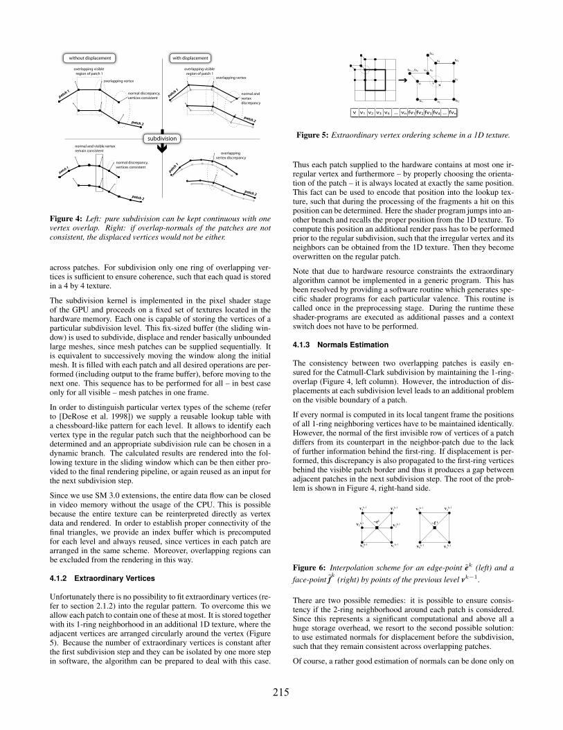
Figure 4: Left: pure subdivision can be kept continuous with onevertex overlap. Right: if overlap-normals of the patches are notconsistent, the displaced vertices would not be either.
across patches. For subdivision only one ring of overlapping ver-tices is sufficient to ensure coherence, such that each quad is storedin a 4 by 4 texture.
The subdivision kernel is implemented in the pixel shader stageof the GPU and proceeds on a fixed set of textures located in thehardware memory. Each one is capable of storing the vertices of aparticular subdivision level. This fix-sized buffer (the sliding win-dow) is used to subdivide, displace and render basically unboundedlarge meshes, since mesh patches can be supplied sequentially. Itis equivalent to successively moving the window along the initialmesh. It is filled with each patch and all desired operations are per-formed (including output to the frame buffer), before moving to thenext one. This sequence has to be performed for all – in best caseonly for all visible – mesh patches in one frame.
In order to distinguish particular vertex types of the scheme (referto [DeRose et al. 1998]) we supply a reusable lookup table witha chessboard-like pattern for each level. It allows to identify eachvertex type in the regular patch such that the neighborhood can bedetermined and an appropriate subdivision rule can be chosen in adynamic branch. The calculated results are rendered into the fol-lowing texture in the sliding window which can be then either pro-vided to the final rendering pipeline, or again reused as an input forthe next subdivision step.
Since we use SM 3.0 extensions, the entire data flow can be closedin video memory without the usage of the CPU. This is possiblebecause the entire texture can be reinterpreted directly as vertexdata and rendered. In order to establish proper connectivity of thefinal triangles, we provide an index buffer which is precomputedfor each level and always reused, since vertices in each patch arearranged in the same scheme. Moreover, overlapping regions canbe excluded from the rendering in this way.
4.1.2 Extraordinary Vertices
Unfortunately there is no possibility to fit extraordinary vertices (re-fer to section 2.1.2) into the regular pattern. To overcome this weallow each patch to contain one of these at most. It is stored togetherwith its 1-ring neighborhood in an additional 1D texture, where theadjacent vertices are arranged circularly around the vertex (Figure5). Because the number of extraordinary vertices is constant afterthe first subdivision step and they can be isolated by one more stepin software, the algorithm can be prepared to deal with this case.
v1
v2
v3
v4
v5 ... vn
fv1 fv2
fv3
fv4
fv5 ... fvn
v
v1 v2 v3 v4 ... vn fv1 fv2 fv3 fv4 fvn...v
Figure 5: Extraordinary vertex ordering scheme in a 1D texture.
Thus each patch supplied to the hardware contains at most one ir-regular vertex and furthermore – by properly choosing the orienta-tion of the patch – it is always located at exactly the same position.This fact can be used to encode that position into the lookup tex-ture, such that during the processing of the fragments a hit on thisposition can be determined. Here the shader program jumps into an-other branch and recalls the proper position from the 1D texture. Tocompute this position an additional render pass has to be performedprior to the regular subdivision, such that the irregular vertex and itsneighbors can be obtained from the 1D texture. Then they becomeoverwritten on the regular patch.
Note that due to hardware resource constraints the extraordinaryalgorithm cannot be implemented in a generic program. This hasbeen resolved by providing a software routine which generates spe-cific shader programs for each particular valence. This routine iscalled once in the preprocessing stage. During the runtime theseshader-programs are executed as additional passes and a contextswitch does not have to be performed.
4.1.3 Normals Estimation
The consistency between two overlapping patches is easily en-sured for the Catmull-Clark subdivision by maintaining the 1-ring-overlap (Figure 4, left column). However, the introduction of dis-placements at each subdivision level leads to an additional problemon the visible boundary of a patch.
If every normal is computed in its local tangent frame the positionsof all 1-ring neighboring vertices have to be maintained identically.However, the normal of the first invisible row of vertices of a patchdiffers from its counterpart in the neighbor-patch due to the lackof further information behind the first-ring. If displacement is per-formed, this discrepancy is also propagated to the first-ring verticesbehind the visible patch border and thus it produces a gap betweenadjacent patches in the next subdivision step. The root of the prob-lem is shown in Figure 4, right-hand side.
~ek ~f k
v1k-1v0
k-1
v3k-1 v2
k-1
v1k-1v0
k-1
v3k-1
v2k-1
v4k-1
v5k-1
Figure 6: Interpolation scheme for an edge-point ek (left) and aface-point f
k(right) by points of the previous level vk−1.
There are two possible remedies: it is possible to ensure consis-tency if the 2-ring neighborhood around each patch is considered.Since this represents a significant computational and above all ahuge storage overhead, we resort to the second possible solution:to use estimated normals for displacement before the subdivision,such that they remain consistent across overlapping patches.
Of course, a rather good estimation of normals can be done only on
215

vertex-points of the current subdivision level because of the pres-ence of the vertex and its 1-ring. If subdivision has not been per-formed, new face- and edge-vertices are not given yet. Our solu-tion is to temporarily estimate the missing edge- and face-pointsin a rather rough way. Each particular point vk (which will be in-troduced in the just after following subdivision step as vk) is bi-linearly interpolated by its surrounding points at level k − 1. Thenits normal is computed as a normalized sum of the cross prod-uct normals of the faces given by the interpolated point vk and itsneighbors vk−1
i (see Figure 6). In fact this approximates the normalon the previous level.
The displacement can be applied just after the subdivision, partic-ularly after the new vertex position has been computed. Althoughthis solution has an impact on the correctness of the displacement,in consideration of the density of the mesh it is negligibly smalland no noticeable drawback can be observed on the visual results.Finally, this solution provides a further benefit: because the esti-mation can be done for each vertex without the knowledge of theproperly placed neighbor points (since information from previouslevel is used), it can be performed just-in-time directly before thesubdivision in the same shader program. This saves an expensiveswitch of render targets in order to compute proper normals, whileexact limit normals can be computed after the last subdivision stepand can be used for the illumination of the final scene.
4.1.4 Displacement Map Continuity
In order to perform displacement on overlapping patches, one fi-nal issue should be taken into account. While a continuous texturecoordinates layer can be kept over adjacent pieces, texture tiles cancause holes between patches if the offset values d do not match eachother at the borders. This problem can be resolved by providing ex-actly tileable textures as displacement maps only.
4.2 Adaptive Subdivision and Displacement
In the decomposed mesh each patch is independent, thus each canbe subdivided and displaced to a certain level. This constellationimplies the possibility of a step-wise adaptive subdivision of thewhole model, such that adjacent patches can be rendered at dif-ferent resolutions depending on the current camera position. Onecan profit from this issue and allow a one-step difference betweenneighboring patches without loss of the geometric coherence of themesh. Vertices of mesh patches at different levels do not lie on thesame positions, however the last positions at the higher sampledmesh are known exactly.
p0
p1
p2
Figure 7: Closing a T-Joint between mesh patches. Left: twopatches of different resolution. Right: the vertices of the highersampled mesh are forced to the lower level. Points p0, p1, p2 forma zero area triangle.
Thus, as a straight-forward solution, the border vertices betweentwo differently sampled meshes can be forced to their positions atthe lower subdivision level. This works quite satisfying for smoothsubdivision, although small micro-holes of pixel-size can still ap-pear during the rendering. The remedy therefore are zero area tri-angles [Losasso and Hoppe 2004]. The triangulation of the final
Figure 8: Adaptive subdivision (left) with displacement (right).
rendering does not depend on the actual connectivity of the meshbut rather is determined by a precomputed index buffer. Just for thisreason, the T-faces can be introduced very easily by including theminto the index-buffer computation routine. A further advantage ofthe zero-area-faces is the fact that indeed during displacement it ishardly possible to keep the borders of differently sampled patchesconsistent. Here the T-triangles do a great job by totally closing anyarising discontinuity (see Figures 7 and 8).
The described procedure behaves very well on regular patch junc-tions, while it is difficult to implement in hardware for extraordi-nary vertices. Fortunately, the number of these is usually very lim-ited in a mesh, thus our method does not allow different resolu-tions on adjacent patches sharing one extraordinary point in orderto avoid those hard cases. In fact - this solution is numerically safeand provides a completely ’watertight’ mesh.
4.3 Rendering
The final rendering routine is a cycling function containing twonested loops (Figure 9). In each frame the outer loop cycles overall patches where in an inner loop each one is subdivided (anddisplaced) depth-first to the desired resolution. Once a patch isfully computed, the resulting geometry-texture is reinterpreted asa vertex-buffer directly in the hardware and an one-for-all, off-lineprecomputed index-buffer is supplied. Here the rendering pipelinemust perform a context switch to change the render target to theframe buffer and load another shader program for visual output.This is the actual bottleneck of the system. The frequent contextswitches of the shader cause the longest delays in the GPU pipeline,reducing the overall utilization of the graphics hardware. While notimplemented in our solution yet, this drawback can be reduced bymaintaining multiple subdivision buffers in video memory in orderto cache and reuse results computed in the rendering stage.
Render Loop
Shader Subdivision Kernel
switch HW context to subdivision
supply index buffer
switch HW context to rendering
bind texture as vertex buffer
Draw Patch to Screen
for each patch do
estimate visibility and resolution
for each patch do
patch HW subdivision level n
PS
PS
patch HW subdivision level n+1
Position Texture Level n
Pos. TextureLevel n+1
subdivide
compute normal
Position Texture Level n
Pos. Texture Level n+1
Lookup Texture Level n+1
subdivide
displace
adjust borders
overwrite extraordinary
estimate normal
Figure 9: Rendering. Left: outer loop. Right: inner loop. Notethat the additional pixel shader pass is performed on demand if anextraordinary point has to be computed.
216

0
2
4
6
3 4 5 6 7 8 9Subdivision Level
Tim
e (s
)
0
10
3 4 5 6 7 8 9Subdivision Level
Tim
e (s
)
level 3 4 5 6 7 8 9
HW (blue) 0,019 0,031 0,046 0,068 0,114 0,273 0,871
SW (red) 0,003 0,006 0,017 0,064 0,267 1,187 4,999
ratio (SW/HW) 0,158 0,194 0,370 0,941 2,342 4,364 5,739
outp. vertices 386 1538 6146 24578 98306 393218 1572866
Figure 10: Evaluation time of traditional software subdivision(red) and our method in hardware (blue). Note the logarithmicscale in the right-hand side chart. Time is given in seconds.
Nonetheless, GPU subdivision results in an significant speedup ifcompared to traditional software implementation based on half-edge data structures, especially at higher steps (Figure 10). De-pending on the hardware, multiple vertices are processed simulta-neously by the GPU. Also, the fact that the computed data stored inthe texture memory can be directly reinterpreted as geometry with-out passing it back to system memory allows to process all this inreal-time.
5 Results
Figure 10 shows the comparison of the evaluation time of recur-sive subdivision performed on half-edge data structures in softwareand our hardware accelerated solution up to level 9. Note that thefirst two steps before hardware subdivision have been computed insoftware to isolate the extraordinary points and to achieve an appro-priate size of mesh patches.
The test has been done on a Intel Core Duo 2.4 Ghz machine with2GB main memory. The graphics was supported by an ATI RadeonX1900 GT GPU with 36 pixel pipelines, 513 Mhz core clock and256 MB installed video memory, 768 MB texture memory and 660Mhz memory clock. The model used for the test is a simple unitcube at original zero level. It is build out of 8 vertices and 6 faces.After two steps the mesh supplied to hardware is already composedof 96 faces. The presented timings are given in seconds and showan average over 80 measured frames.
In terms of the ratio of the compared runtimes can be seen that thecomplexity of the hardware does not follow the same increase as ofthe software. This appears obvious due to the parallelization of theGPU. On the third step (which is the first one in hardware) the GPUis in fact slower than software, while on the ninth step it is almost6 times faster. The low subdivision steps are slower than the higherdue to the overhead of the initialization and bad utilization of thepipeline. It is not designed to process very small textures, becausethe data and instructions transfer cause a relatively large overheadif compared to the contained information. Processing of larger tex-tures would reduce this overhead. Currently we are working onan improved implementation which resolves this problem and alsotakes advantage of recently introduced hardware extensions.
6 Conclusions
We have presented a method for displacing subdivision surfaces onseveral resolutions by the means of spectrally decomposed patterns.
In fact, to the authors knowledge, such an approach has not beenattempted yet.
The multiscale displacement approach provides the ability to fine-tune the visual output on-the-fly in many variations by rather in-tuitive control. To compare this method to classical displacement,one issue should be considered as significant extension: Usuallydisplacement is applied only once on the final tessellation, whichlimits this technique to a one-time shift of the surfaces’ vertices.This does not allow the ability to achieve coarse deformations ofthe entire object with additional small features along the deformedsurface. This issue has been extended by the adaption of multires-olution displacement such that a vertex from the initial mesh canbe moved several times in different directions, each affected by theprevious subdivision steps.
As an additional goal, the entire subdivision and displacement pro-cedure has been shown to be able to perform in real-time on a pro-grammable graphics accelerator with very high mesh tessellations.This work was very much concerned on the issue of real-time per-formance. More precisely, many limitations had to be taken intoaccount in order to achieve such an implementation, especially theissue of keeping the borders of adjacent patches continuous duringseveral displacement steps. Generally, our prototype achieves inter-active frame rates with approx. 100.000 vertices (10 fps), which allbecome re-computed each frame from approx. 30 initial points ona moderate hardware. These rates might be significantly increasedby the introduction of caching strategies.
In order to improve the visual quality additional extensions are con-ceivable:
• In the adaptive approach, the additional detail of finer subdi-vision levels could be introduced continuously, by scaling thedisplacements based on the viewer distance during the changefrom one subdivision level to the next.
• The borders that are forced to the coarser subdivision level inadaptive subdivision could be modified to a linear transitionzone between differing subdivision levels.
The implementation can be seen as a starting point for further opti-mizations in order to ensure optimal performance on different hard-ware. Considering the current development of the graphics acceler-ators, we are working on an implementation which uses new exten-sions (geometry shader) in order improve our method. We believethat this technique is very well suited to be used for modeling ofmultiscale details even on large meshes.
Figure 11: Tree bark rendered with texture applied.
217

Acknowledgments
The authors would like to thank Anton Fuhrmann and ChrystophToll for their supporting hints and discussions. Most of this workhas been done at the VRVis Research Center in Vienna, Austria,which is partially founded by the Austrian government researchprogram Kplus. Parts of this work have also been funded by theAustrian Science Fund (FWF) under project P17260-N04.
ReferencesBIERMANN, H., LEVIN, A., AND ZORIN, D. 2000. Piecewise smooth
subdivision surfaces with normal control. In ACM SIGGRAPH 2000:Proceedings of the 27th annual conference on Computer graphics and in-teractive techniques, ACM Press/Addison-Wesley Publishing Co., NewYork, NY, USA, 113–120.
BIERMANN, H., MARTIN, I. M., ZORIN, D., AND BERNARDINI, F. 2002.Sharp features on multiresolution subdivision surfaces. Graph. Models64, 2, 61–77.
BISCHOFF, S., KOBBELT, L. P., AND SEIDEL, H.-P. 2000. Towardshardware implementation of loop subdivision. In Proceedings of the2000 SIGGRAPH/EUROGRAPHICS Workshop on Graphics Hardware(EGGH-00), ACM Press, N. Y., S. N. Spencer, Ed., 41–50.
BLINN, J. F. 1978. Simulation of wrinkled surfaces. In ACM SIGGRAPH78: Proceedings of the 5th annual conference on Computer graphics andinteractive techniques, ACM Press, New York, NY, USA, 286–292.
BOIER-MARTIN, I., AND ZORIN, D. 2004. Differentiable parameteri-zation of catmull-clark subdivision surfaces. In Eurographics Sympo-sium on Geometry Processing, Eurographics Association, Nice, France,R. Scopigno and D. Zorin, Eds., 159–168.
BOLZ, J., AND SCHRODER, P. 2002. Rapid evaluation of catmull-clarksubdivision surfaces. In Proceedings of the Web3D 2002 Symposium(WEB3D-02), ACM Press, New York, 11–18.
BOLZ, J., AND SCHRODER, P. 2003. Evaluation of sub-division surfaces on programmable graphics hardware. Inhttp://www.multires.caltech.edu/pubs/GPUSubD.pdf.
BURT, P. J., AND ADELSON, E. H. 1983. The laplacian pyramid as acompact image code. IEEE Trans. on Communications, 4 (Apr.).
CATMULL, E., AND CLARK, J. 1978. Recursively generated B-splinesurfaces on arbitrary topological meshes. Computer-Aided Design 10(Sept.), 350–355.
COOK, R. L. 1984. Shade trees. In ACM SIGGRAPH 84: Proceedings ofthe 11th annual conference on Computer graphics and interactive tech-niques, ACM Press, New York, NY, USA, 223–231.
DEROSE, T., KASS, M., AND TRUONG, T. 1998. Subdivision surfaces incharacter animation. In ACM SIGGRAPH 98: Proceedings of the 25thannual conference on Computer graphics and interactive techniques,ACM Press, New York, NY, USA, 85–94.
DOO, D., AND SABIN, M. 1978. Behaviour of recursive division surfacesnear extraordinary points. Computer-Aided Design 10 (Sept.), 356–360.
HALSTEAD, M., KASS, M., AND DEROSE, T. 1993. Efficient, fair inter-polation using catmull-clark surfaces. In ACM SIGGRAPH 93: Proceed-ings of the 20th annual conference on Computer graphics and interactivetechniques, ACM Press, New York, NY, USA, 35–44.
KHODAKOVSKY, A., AND SCHRODER, P. 1999. Fine level feature editingfor subdivision surfaces. In SMA ’99: Proceedings of the fifth ACMsymposium on Solid modeling and applications, ACM Press, New York,NY, USA, 203–211.
LEE, A., MORETON, H., AND HOPPE, H. 2000. Displaced subdivi-sion surfaces. In ACM SIGGRAPH 2000: Proceedings of the 27th an-nual conference on Computer graphics and interactive techniques, ACMPress/Addison-Wesley Publishing Co., New York, NY, USA, 85–94.
LOSASSO, F., AND HOPPE, H. 2004. Geometry clipmaps: terrain render-ing using nested regular grids. ACM Trans. Graph. 23, 3, 769–776.
Figure 12: A bag with calf leather and folds patterns.
MULLER, K., AND HAVEMANN, S. 2000. Subdivision surface tesselationon the fly using a versatile mesh data structure. In Proceedings of the21th European Conference on Computer Graphics (EG-00), BlackwellPublishers, Cambridge, S. Coquillart and J. Duke, David, Eds., vol. 19,3 of Computer Graphics Forum, 151–160.
OLIVEIRA, M. M., BISHOP, G., AND MCALLISTER, D. 2000. Relief tex-ture mapping. In ACM SIGGRAPH 2000: Proceedings of the 27th an-nual conference on Computer graphics and interactive techniques, ACMPress/Addison-Wesley Publishing Co., New York, NY, USA, 359–368.
PETERS, J. 2000. Patching catmull-clark meshes. In ACM SIGGRAPH2000: Proceedings of the 27th annual conference on Computer graphicsand interactive techniques, ACM Press/Addison-Wesley Publishing Co.,New York, NY, USA, 255–258.
PHARR, M., AND FERNANDO, R. 2005. GPU Gems 2 : ProgrammingTechniques for High-Performance Graphics and General-Purpose Com-putation. Addison-Wesley Professional, March.
PULLI, K., AND SEGAL, M. 1996. Fast rendering of subdivision surfaces.In ACM SIGGRAPH 96 Visual Proceedings., ACM Press, New York,NY, USA, 144.
REIF, U. 1995. A unified approach to subdivision algorithms near extraor-dinary vertices. Computer Aided Geometric Design 12, 2, 153–174.
SEDERBERG, T. W., ZHENG, J., SEWELL, D., AND SABIN, M. 1998.Non-uniform recursive subdivision surfaces. In ACM SIGGRAPH 98:Proceedings of the 25th annual conference on Computer graphics andinteractive techniques, ACM Press, New York, NY, USA, 387–394.
SETTGAST, V., MULLER, K., FUNFZIG, C., AND FELLNER, D. W. 2004.Adaptive tesselation of subdivision surfaces. Computers & Graphics 28,1, 73–78.
SHIUE, L.-J., JONES, I., AND PETERS, J. 2005. A realtime gpu subdivi-sion kernel. In ACM SIGGRAPH 2005 Proceedings, ACM Press, NewYork, NY, USA, 1010–1015.
STAM, J. 1998. Exact evaluation of catmull-clark subdivision surfacesat arbitrary parameter values. In ACM SIGGRAPH 98: Proceedings ofthe 25th annual conference on Computer graphics and interactive tech-niques, ACM Press, New York, NY, USA, 395–404.
TOBLER, R. F., MAIERHOFER, S., AND WILKIE, A. 2002. A multires-olution mesh generation approach for procedural definition of complexgeometry. In SMI ’02: Proceedings of the Shape Modeling International2002 (SMI’02), IEEE Computer Society, Washington, DC, USA, 35.
VELHO, L., PERLIN, K., YING, L., AND BIERMANN, H. 2001. Procedu-ral shape synthesis on subdivision surfaces. In SIBGRAPI ’01: Proceed-ings of the 14th Brazilian Symposium on Computer Graphics and ImageProcessing, IEEE Computer Society, Washington, DC, USA, 146–153.
YING, L., AND ZORIN, D. 2001. Nonmanifold subdivision. In IEEE Visu-alization 2001, October 24-26, 2001, San Diego, CA, USA, Proceedings,IEEE Computer Society, T. Ertl, K. I. Joy, and A. Varshney, Eds.
ZORIN, D., AND KRISTJANSSON, D. 2002. Evaluation of piecewisesmooth subdivision surfaces. The Visual Computer 18, 5-6, 299–315.
218
Related Documents


![Multiresolution control of curves and surfaces with a self ... · jects. Blanc-Talon [16] introduced an interpolation system with spline-based approxi-mation. Coefficients of subdivision](https://static.cupdf.com/doc/110x72/5f3fab70ad3ed336aa3d78c8/multiresolution-control-of-curves-and-surfaces-with-a-self-jects-blanc-talon.jpg)