Chapter 5 Multipath Wave Propagation and Fading 5.1 Multipath Propagation In wireless telecommunications, multipath is the propagation phenomenon that re- sults in radio signals reaching the receiving antenna by two or more paths. Causes of multipath include atmospheric ducting, ionospheric reflection and refraction, and reflection from water bodies and terrestrial objects such as mountains and buildings. The effects of multipath include constructive and destructive interference, and phase shifting of the signal. In digital radio communications (such as GSM) multipath can cause errors and affect the quality of communications. We discuss all the related issues in this chapter. 5.2 Multipath & Small-Scale Fading Multipath signals are received in a terrestrial environment, i.e., where different forms of propagation are present and the signals arrive at the receiver from transmitter via a variety of paths. Therefore there would be multipath interference, causing multi- path fading. Adding the effect of movement of either Tx or Rx or the surrounding clutter to it, the received overall signal amplitude or phase changes over a small amount of time. Mainly this causes the fading. 75

Welcome message from author
This document is posted to help you gain knowledge. Please leave a comment to let me know what you think about it! Share it to your friends and learn new things together.
Transcript

Chapter 5
Multipath Wave Propagation
and Fading
5.1 Multipath Propagation
In wireless telecommunications, multipath is the propagation phenomenon that re-
sults in radio signals reaching the receiving antenna by two or more paths. Causes
of multipath include atmospheric ducting, ionospheric reflection and refraction, and
reflection from water bodies and terrestrial objects such as mountains and buildings.
The effects of multipath include constructive and destructive interference, and phase
shifting of the signal. In digital radio communications (such as GSM) multipath can
cause errors and affect the quality of communications. We discuss all the related
issues in this chapter.
5.2 Multipath & Small-Scale Fading
Multipath signals are received in a terrestrial environment, i.e., where different forms
of propagation are present and the signals arrive at the receiver from transmitter via
a variety of paths. Therefore there would be multipath interference, causing multi-
path fading. Adding the effect of movement of either Tx or Rx or the surrounding
clutter to it, the received overall signal amplitude or phase changes over a small
amount of time. Mainly this causes the fading.
75
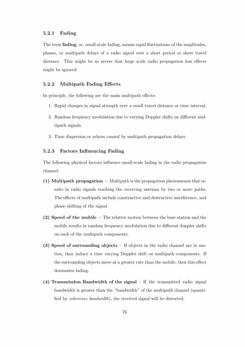
5.2.1 Fading
The term fading, or, small-scale fading, means rapid fluctuations of the amplitudes,
phases, or multipath delays of a radio signal over a short period or short travel
distance. This might be so severe that large scale radio propagation loss effects
might be ignored.
5.2.2 Multipath Fading Effects
In principle, the following are the main multipath effects:
1. Rapid changes in signal strength over a small travel distance or time interval.
2. Random frequency modulation due to varying Doppler shifts on different mul-
tipath signals.
3. Time dispersion or echoes caused by multipath propagation delays.
5.2.3 Factors Influencing Fading
The following physical factors influence small-scale fading in the radio propagation
channel:
(1) Multipath propagation – Multipath is the propagation phenomenon that re-
sults in radio signals reaching the receiving antenna by two or more paths.
The effects of multipath include constructive and destructive interference, and
phase shifting of the signal.
(2) Speed of the mobile – The relative motion between the base station and the
mobile results in random frequency modulation due to different doppler shifts
on each of the multipath components.
(3) Speed of surrounding objects – If objects in the radio channel are in mo-
tion, they induce a time varying Doppler shift on multipath components. If
the surrounding objects move at a greater rate than the mobile, then this effect
dominates fading.
(4) Transmission Bandwidth of the signal – If the transmitted radio signal
bandwidth is greater than the “bandwidth” of the multipath channel (quanti-
fied by coherence bandwidth), the received signal will be distorted.
76
5.3 Types of Small-Scale Fading
The type of fading experienced by the signal through a mobile channel depends
on the relation between the signal parameters (bandwidth, symbol period) and the
channel parameters (rms delay spread and Doppler spread). Hence we have four
different types of fading. There are two types of fading due to the time dispersive
nature of the channel.
5.3.1 Fading Effects due to Multipath Time Delay Spread
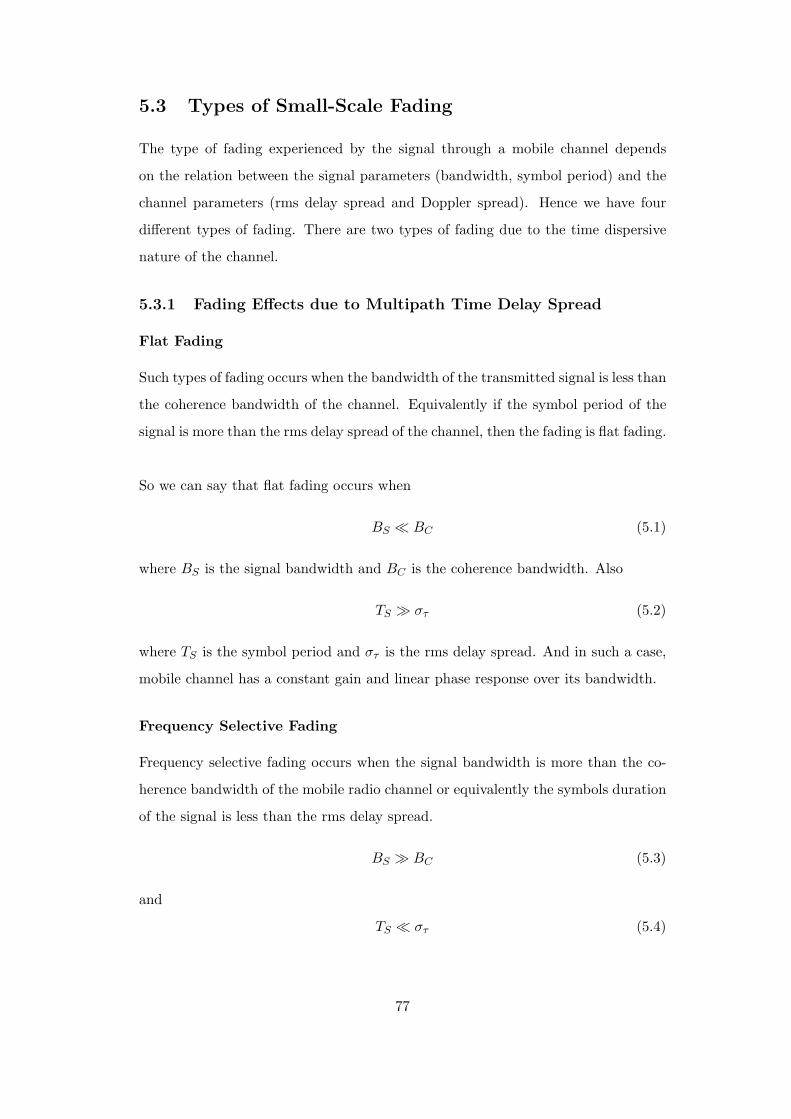
Flat Fading
Such types of fading occurs when the bandwidth of the transmitted signal is less than
the coherence bandwidth of the channel. Equivalently if the symbol period of the
signal is more than the rms delay spread of the channel, then the fading is flat fading.
So we can say that flat fading occurs when
BS BC (5.1)
where BS is the signal bandwidth and BC is the coherence bandwidth. Also
TS στ (5.2)
where TS is the symbol period and στ is the rms delay spread. And in such a case,
mobile channel has a constant gain and linear phase response over its bandwidth.
Frequency Selective Fading
Frequency selective fading occurs when the signal bandwidth is more than the co-
herence bandwidth of the mobile radio channel or equivalently the symbols duration
of the signal is less than the rms delay spread.
BS BC (5.3)
and
TS στ (5.4)
77
At the receiver, we obtain multiple copies of the transmitted signal, all attenuated
and delayed in time. The channel introduces inter symbol interference. A rule of
thumb for a channel to have flat fading is if
στ
TS≤ 0.1 (5.5)
5.3.2 Fading Effects due to Doppler Spread
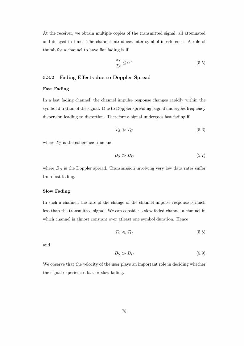
Fast Fading
In a fast fading channel, the channel impulse response changes rapidly within the
symbol duration of the signal. Due to Doppler spreading, signal undergoes frequency
dispersion leading to distortion. Therefore a signal undergoes fast fading if
TS TC (5.6)
where TC is the coherence time and
BS BD (5.7)
where BD is the Doppler spread. Transmission involving very low data rates suffer
from fast fading.
Slow Fading
In such a channel, the rate of the change of the channel impulse response is much
less than the transmitted signal. We can consider a slow faded channel a channel in
which channel is almost constant over atleast one symbol duration. Hence
TS TC (5.8)
and
BS BD (5.9)
We observe that the velocity of the user plays an important role in deciding whether
the signal experiences fast or slow fading.
78

Figure 5.1: Illustration of Doppler effect.
5.3.3 Doppler Shift
The Doppler effect (or Doppler shift) is the change in frequency of a wave for an
observer moving relative to the source of the wave. In classical physics (waves in
a medium), the relationship between the observed frequency f and the emitted
frequency fo is given by:
f =(
v ± vr
v ± vs
)f0 (5.10)
where v is the velocity of waves in the medium, vs is the velocity of the source
relative to the medium and vr is the velocity of the receiver relative to the medium.
In mobile communication, the above equation can be slightly changed according
to our convenience since the source (BS) is fixed and located at a remote elevated
level from ground. The expected Doppler shift of the EM wave then comes out to
be ±vrc fo or, ±vr
λ . As the BS is located at an elevated place, a cos φ factor would
also be multiplied with this. The exact scenario, as given in Figure 5.1, is illustrated
below.
Consider a mobile moving at a constant velocity v, along a path segment length
d between points A and B, while it receives signals from a remote BS source S. The
difference in path lengths traveled by the wave from source S to the mobile at points
A and B is ∆l = d cos θ = v∆t cos θ, where ∆t is the time required for the mobile
to travel from A to B, and θ is assumed to be the same at points A and B since the
79
source is assumed to be very far away. The phase change in the received signal due
to the difference in path lengths is therefore
∆ϕ =2π∆l
λ=
2πv∆t
λcos θ (5.11)
and hence the apparent change in frequency, or Doppler shift (fd) is
fd =12π
.∆ϕ
∆t=
v
λ. cos θ. (5.12)
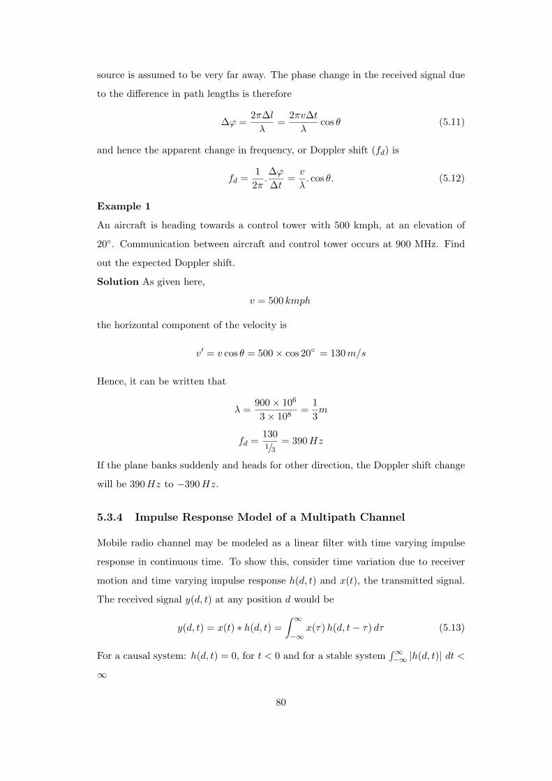
Example 1
An aircraft is heading towards a control tower with 500 kmph, at an elevation of
20. Communication between aircraft and control tower occurs at 900 MHz. Find
out the expected Doppler shift.
Solution As given here,
v = 500 kmph
the horizontal component of the velocity is
v′ = v cos θ = 500 × cos 20 = 130m/s
Hence, it can be written that
λ =900 × 106
3 × 108=
13m
fd =1301/3
= 390Hz
If the plane banks suddenly and heads for other direction, the Doppler shift change
will be 390 Hz to −390 Hz.
5.3.4 Impulse Response Model of a Multipath Channel
Mobile radio channel may be modeled as a linear filter with time varying impulse
response in continuous time. To show this, consider time variation due to receiver
motion and time varying impulse response h(d, t) and x(t), the transmitted signal.
The received signal y(d, t) at any position d would be
y(d, t) = x(t) ∗ h(d, t) =∫ ∞
−∞x(τ) h(d, t − τ) dτ (5.13)
For a causal system: h(d, t) = 0, for t < 0 and for a stable system∫∞−∞ |h(d, t)| dt <
∞
80
Applying causality condition in the above equation, h(d, t − τ) = 0 for t − τ < 0
⇒ τ > t, i.e., the integral limits are changed to
y(d, t) =∫ t
−∞x(τ) h(d, t − τ) dτ.
Since the receiver moves along the ground at a constant velocity v, the position of
the receiver is d = vt, i.e.,
y(vt, t) =∫ t
−∞x(τ) h(vt, t − τ) dτ.
Since v is a constant, y(vt, t) is just a function of t. Therefore the above equation
can be expressed as
y(t) =∫ t
−∞x(τ) h(vt, t − τ) dτ = x(t) ∗ h(vt, t) = x(t) ∗ h(d, t) (5.14)
It is useful to discretize the multipath delay axis τ of the impulse response into equal
time delay segments called excess delay bins, each bin having a time delay width
equal to ( τi+1 − τi) = ∆τ and τi = i∆τ for i ∈ 0, 1, 2, ..N − 1, where N represents
the total number of possible equally-spaced multipath components, including the
first arriving component. The useful frequency span of the model is 2/∆τ . The
model may be used to analyze transmitted RF signals having bandwidth less than
2/∆τ .
If there are N multipaths, maximum excess delay is given by N∆τ .
y(t) = x(t) ∗ h(t, τi)|i = 0, 1, ...N − 1 (5.15)
Bandpass channel impulse response model is
x(t) → h(t, τ) = Rehb(t, τ)ejωct → y(t) = Rer(t)ejωct (5.16)
Baseband equivalent channel impulse response model is given by
c(t) → 12hb(t, τ) → r(t) = c(t) ∗ 1
2hb(t, τ) (5.17)
Average power is
x2(t) =12|c(t)|2 (5.18)
81
The baseband impulse response of a multipath channel can be expressed as
hb(t, τ) =N−1∑i=0
ai(t, τ) exp[j(2πfcτi(t) + ϕi(t, τ))]δ(τ − τi(t)) (5.19)
where ai(t, τ) and τi(t) are the real amplitudes and excess delays, respectively, of
the ith multipath component at time t. The phase term 2πfcτi(t) + ϕi(t, τ) in the
above equation represents the phase shift due to free space propagation of the ith
multipath component, plus any additional phase shifts which are encountered in the
channel.
If the channel impulse response is wide sense stationary over a small-scale time or
distance interval, then
hb(τ) =N−1∑i=0
ai exp[jθi]δ(τ − τi) (5.20)
For measuring hb(τ), we use a probing pulse to approximate δ(t) i.e.,
p(t) ≈ δ(t − τ) (5.21)
Power delay profile is taken by spatial average of |hb(t, τ)|2 over a local area. The
received power delay profile in a local area is given by
p(τ) ≈ k|hb(t; τ)|2. (5.22)
5.3.5 Relation Between Bandwidth and Received Power
In actual wireless communications, impulse response of a multipath channel is mea-
sured using channel sounding techniques. Let us consider two extreme channel
sounding cases.
Consider a pulsed, transmitted RF signal
x(t) = Rep(t)ej2πfct (5.23)
where p(t) =√
4τmaxTbb
for 0 ≤ t ≤ Tbb and 0 elsewhere. The low pass channel output
is
r(t) =12
N−1∑i=0
ai exp[jθi]p(t − τi)
=N−1∑i=0
ai exp[jθi].√
τmax
Tbbrect(t − Tb
2− τi).
82
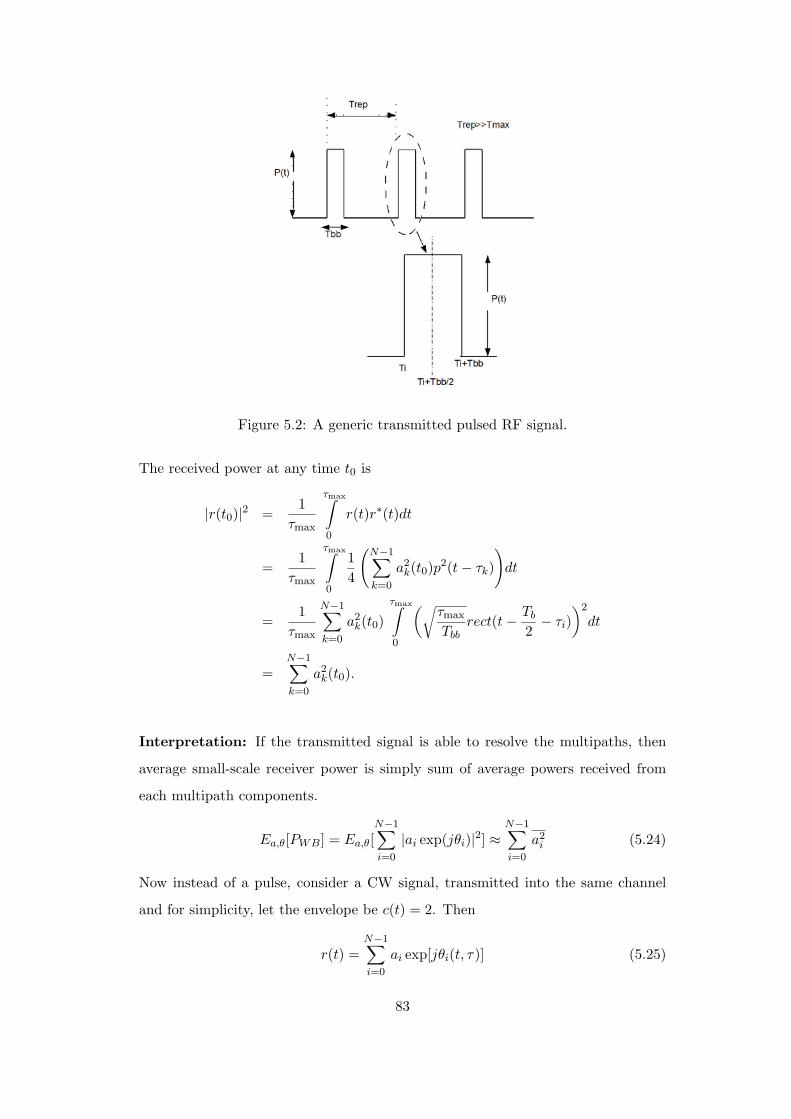
Figure 5.2: A generic transmitted pulsed RF signal.
The received power at any time t0 is
|r(t0)|2 =1
τmax
τmax∫0
r(t)r∗(t)dt
=1
τmax
τmax∫0
14
(N−1∑k=0
a2k(t0)p
2(t − τk)
)dt
=1
τmax
N−1∑k=0
a2k(t0)
τmax∫0
(√τmax
Tbbrect(t − Tb
2− τi)
)2
dt
=N−1∑k=0
a2k(t0).
Interpretation: If the transmitted signal is able to resolve the multipaths, then
average small-scale receiver power is simply sum of average powers received from
each multipath components.
Ea,θ[PWB] = Ea,θ[N−1∑i=0
|ai exp(jθi)|2] ≈N−1∑i=0
a2i (5.24)
Now instead of a pulse, consider a CW signal, transmitted into the same channel
and for simplicity, let the envelope be c(t) = 2. Then
r(t) =N−1∑i=0
ai exp[jθi(t, τ)] (5.25)
83
and the instantaneous power is
|r(t)|2 = |N−1∑i=0
ai exp[jθi(t, τ)]|2 (5.26)
Over local areas, ai varies little but θi varies greatly resulting in large fluctuations.
Ea,θ[PCW ] = Ea,θ[N−1∑i=0
|ai exp(jθi)|2]
≈N−1∑i=0
a2i + 2
N−1∑i=0
N∑i,j =i
rijcos(θi − θj)
where rij = Ea[aiaj ].
If, rij = cos(θi − θj) = 0, then Ea,θ[PCW ] = Ea,θ[PWB]. This occurs if multipath
components are uncorrelated or if multipath phases are i.i.d over [0, 2π].
Bottomline:
1. If the signal bandwidth is greater than multipath channel bandwidth then
fading effects are negligible
2. If the signal bandwidth is less than the multipath channel bandwidth, large
fading occurs due to phase shift of unresolved paths.
5.3.6 Linear Time Varying Channels (LTV)
The time variant transfer function(TF) of an LTV channel is FT of h(t, τ) w.r.t. τ .
H(f, t) = FT [h(τ, t)] =∫ ∞
−∞h(τ, t)e−j2πfτ dτ (5.27)
h(τ, t) = FT−1[H(f, t)] =∫ ∞
−∞H(f, t)ej2πfτ df (5.28)
The received signal
r(t) =∫ ∞
−∞R(f, t)ej2πft df (5.29)
where R(f, t) = H(f, t)X(f).
For flat fading channel, h(τ, t) = Z(t)δ(τ − τi) where Z(t) =∑
αn(t)e−j2πfcτn(t). In
this case, the received signal is
r(t) =∫ ∞
−∞h(τ, t)x(t − τ) dτ = Z(t)x(t − τi) (5.30)
84
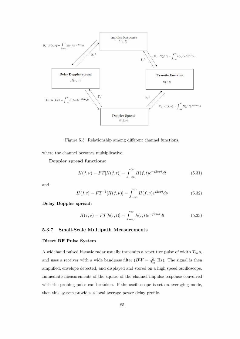
Figure 5.3: Relationship among different channel functions.
where the channel becomes multiplicative.
Doppler spread functions:
H(f, ν) = FT [H(f, t)] =∫ ∞
−∞H(f, t)e−j2πνtdt (5.31)
and
H(f, t) = FT−1[H(f, ν)] =∫ ∞
−∞H(f, ν)ej2πνtdν (5.32)
Delay Doppler spread:
H(τ, ν) = FT [h(τ, t)] =∫ ∞
−∞h(τ, t)e−j2πνtdt (5.33)
5.3.7 Small-Scale Multipath Measurements
Direct RF Pulse System
A wideband pulsed bistatic radar usually transmits a repetitive pulse of width Tbb s,
and uses a receiver with a wide bandpass filter (BW = 2Tbb
Hz). The signal is then
amplified, envelope detected, and displayed and stored on a high speed oscilloscope.
Immediate measurements of the square of the channel impulse response convolved
with the probing pulse can be taken. If the oscilloscope is set on averaging mode,
then this system provides a local average power delay profile.
85
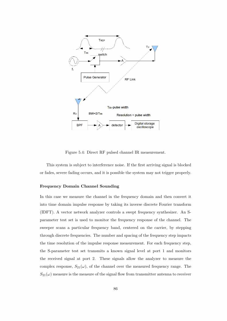
Figure 5.4: Direct RF pulsed channel IR measurement.
This system is subject to interference noise. If the first arriving signal is blocked
or fades, severe fading occurs, and it is possible the system may not trigger properly.
Frequency Domain Channel Sounding
In this case we measure the channel in the frequency domain and then convert it
into time domain impulse response by taking its inverse discrete Fourier transform
(IDFT). A vector network analyzer controls a swept frequency synthesizer. An S-
parameter test set is used to monitor the frequency response of the channel. The
sweeper scans a particular frequency band, centered on the carrier, by stepping
through discrete frequencies. The number and spacing of the frequency step impacts
the time resolution of the impulse response measurement. For each frequency step,
the S-parameter test set transmits a known signal level at port 1 and monitors
the received signal at port 2. These signals allow the analyzer to measure the
complex response, S21(ω), of the channel over the measured frequency range. The
S21(ω) measure is the measure of the signal flow from transmitter antenna to receiver
86
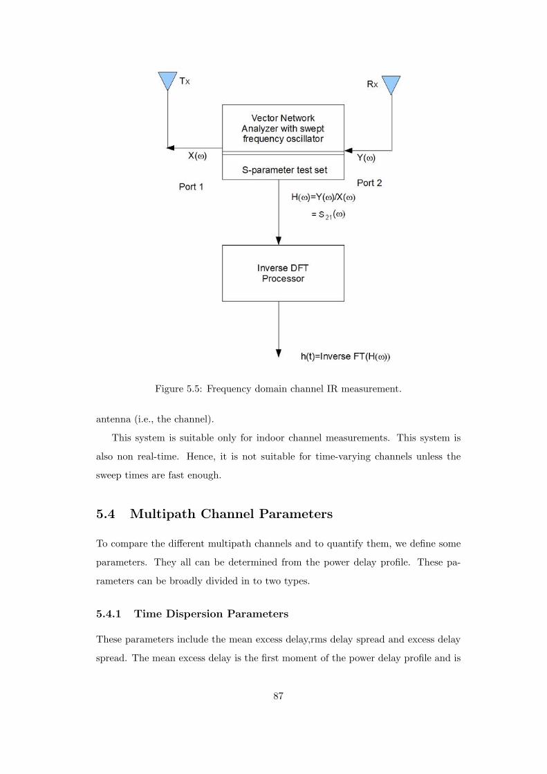
Figure 5.5: Frequency domain channel IR measurement.
antenna (i.e., the channel).
This system is suitable only for indoor channel measurements. This system is
also non real-time. Hence, it is not suitable for time-varying channels unless the
sweep times are fast enough.
5.4 Multipath Channel Parameters
To compare the different multipath channels and to quantify them, we define some
parameters. They all can be determined from the power delay profile. These pa-
rameters can be broadly divided in to two types.
5.4.1 Time Dispersion Parameters
These parameters include the mean excess delay,rms delay spread and excess delay
spread. The mean excess delay is the first moment of the power delay profile and is
87

defined as
τ =∑
a2kτk∑a2
k
=∑
P (τk)τk∑P (τk)
(5.34)
where ak is the amplitude, τk is the excess delay and P (τk) is the power of the
individual multipath signals.
The mean square excess delay spread is defined as
τ2 =∑
P (τk)τ2k∑
P (τk)(5.35)
Since the rms delay spread is the square root of the second central moment of the
power delay profile, it can be written as
στ =√
τ2 − (τ)2 (5.36)
As a rule of thumb, for a channel to be flat fading the following condition must be
satisfiedστ
TS≤ 0.1 (5.37)
where TS is the symbol duration. For this case, no equalizer is required at the
receiver.
Example 2
1. Sketch the power delay profile and compute RMS delay spread for the follow-
ing:
P (τ) =1∑
n=0δ(τ − n × 10−6) (in watts)
2. If BPSK modulation is used, what is the maximum bit rate that can be sent
through the channel without needing an equalizer?
Solution
1. P (0) = 1 watt, P (1) = 1 watt
τ =(1)(0) + (1)(1)
1 + 1= 0.5µs
τ2 = 0.5µs2 στ = 0.5µs
88

2. For flat fading channel, we need στTs
0.1 ⇒ Rs = 1Ts
= 0.2 × 104 = 200 kbps
For BPSK we need Rb = Rs = 200 kbps
Example 3 A simple delay spread bound: Feher’s upper bound
Consider a simple worst-case delay spread scenario as shown in figure below.
Here dmin = d0 and dmax = di + dr
Transmitted power = PT , Minimum received power = PRmin = PThreshold
PRmin
PT= GT GR(
λ
4πdmax)2
Put GT = GR = 1 i.e., considering omni-directional unity gain antennas
dmax = (λ
4π)(
PT
PRmin
)12
τmax =dmax
c= (
λ
4πc)(
PT
PRmin
)12
τmax = (1
4πf)(
PT
PRmin
)12
5.4.2 Frequency Dispersion Parameters
To characterize the channel in the frequency domain, we have the following param-
eters.
89

(1) Coherence bandwidth: it is a statistical measure of the range of frequencies
over which the channel can be considered to pass all the frequency components with
almost equal gain and linear phase. When this condition is satisfied then we say the
channel to be flat.
Practically, coherence bandwidth is the minimum separation over which the two
frequency components are affected differently. If the coherence bandwidth is con-
sidered to be the bandwidth over which the frequency correlation function is above
0.9, then it is approximated as
BC ≈ 150στ
. (5.38)
However, if the coherence bandwidth is considered to be the bandwidth over which
the frequency correlation function is above 0.5, then it is defined as
BC ≈ 15στ
. (5.39)
The coherence bandwidth describes the time dispersive nature of the channel in the
local area. A more convenient parameter to study the time variation of the channel
is the coherence time. This variation may be due to the relative motion between the
mobile and the base station or the motion of the objects in the channel.
(2) Coherence time: this is a statistical measure of the time duration over which
the channel impulse response is almost invariant. When channel behaves like this,
it is said to be slow faded. Essentially it is the minimum time duration over which
two received signals are affected differently. For an example, if the coherence time
is considered to be the bandwidth over which the time correlation is above 0.5, then
it can be approximated as
TC ≈ 916πfm
(5.40)
where fm is the maximum doppler spread given be fm = νλ .
Another parameter is the Doppler spread (BD) which is the range of frequencies
over which the received Doppler spectrum is non zero.
5.5 Statistical models for multipath propagation
Many multipath models have been proposed to explain the observed statistical na-
ture of a practical mobile channel. Both the first order and second order statistics
90
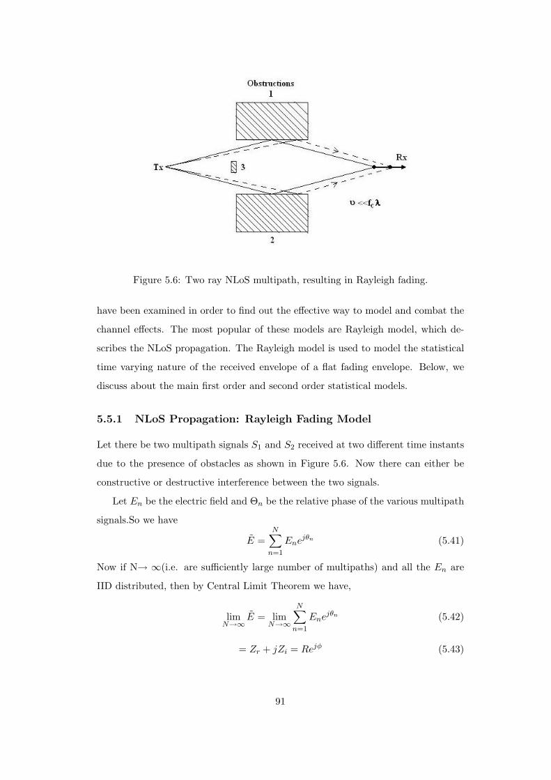
Figure 5.6: Two ray NLoS multipath, resulting in Rayleigh fading.
have been examined in order to find out the effective way to model and combat the
channel effects. The most popular of these models are Rayleigh model, which de-
scribes the NLoS propagation. The Rayleigh model is used to model the statistical
time varying nature of the received envelope of a flat fading envelope. Below, we
discuss about the main first order and second order statistical models.
5.5.1 NLoS Propagation: Rayleigh Fading Model
Let there be two multipath signals S1 and S2 received at two different time instants
due to the presence of obstacles as shown in Figure 5.6. Now there can either be
constructive or destructive interference between the two signals.
Let En be the electric field and Θn be the relative phase of the various multipath
signals.So we have
E =N∑
n=1
Enejθn (5.41)
Now if N→ ∞(i.e. are sufficiently large number of multipaths) and all the En are
IID distributed, then by Central Limit Theorem we have,
limN→∞
E = limN→∞
N∑n=1
Enejθn (5.42)
= Zr + jZi = Rejφ (5.43)
91
where Zr and Zi are Gaussian Random variables. For the above case
R =√
Z2r + Z2
i (5.44)
and
φ = tan−1 Zi
Zr(5.45)
For all practical purposes we assume that the relative phase Θn is uniformaly dis-
tributed.
E[ejθn ] =12π
2π∫0
ejθdθ = 0 (5.46)
It can be seen that En and Θn are independent. So,
E[E] = E[∑
Enejθn ] = 0 (5.47)
E[∣∣∣E∣∣∣2] = E[
∑Enejθn
∑E∗
ne−jθn ] = E[∑m
∑n
EnEmej(θn−θm)] =N∑
n=1
E2n = P0
(5.48)
where P0 is the total power obtained. To find the Cumulative Distribution Func-
tion(CDF) of R, we proceed as follows.
FR(r) = Pr(R ≤ r) =∫A
∫fZi,Zr(zi, zr)dzidzr (5.49)
where A is determined by the values taken by the dummy variable r. Let Zi and Zr
be zero mean Gaussian RVs. Hence the CDF can be written as
FR(r) =∫A
∫ 1√2πσ2
e−(Z2
r+Z2i)
2σ2 dZidZr (5.50)
Let Zr = p cos(Θ) and Zi = p sin(Θ) So we have
FR(r) =2π∫0
2π∫0
1√2πσ2
e−p2
2σ2 pdpdθ (5.51)
= 1 − e−r2
2σ2 (5.52)
Above equation is valid for all r ≥ 0. The pdf can be written as
fR(r) =r
σ2e−
r2
2σ2 (5.53)
and is shown in Figure 5.7 with different σ values. This equation too is valid for all
r ≥ 0. Above distribution is known as Rayleigh distribution and it has been derived
92

Figure 5.7: Rayleigh probability density function.
for slow fading. However, if fD 1 Hz, we call it as Quasi-stationary Rayleigh
fading. We observe the following:
E[R] =√
π
2σ (5.54)
E[R2] = 2σ2 (5.55)
var[R] = (2 − π
2)σ2 (5.56)
median[R] = 1.77σ. (5.57)
5.5.2 LoS Propagation: Rician Fading Model
Rician Fading is the addition to all the normal multipaths a direct LOS path.
Figure 5.8: Ricean probability density function.
93
fR(r) =r
σ2e
−(r2+A2)
2σ2 I0(Ar
σ2) (5.58)
for all A ≥ 0 and r ≥ 0. Here A is the peak amplitude of the dominant signal and
I0(.) is the modified Bessel function of the first kind and zeroth order.
A factor K is defined as
KdB = 10 logA2
2σ2(5.59)
As A → 0 then KdB → ∞.
5.5.3 Generalized Model: Nakagami Distribution
A generalization of the Rayleigh and Rician fading is the Nakagami distribution.
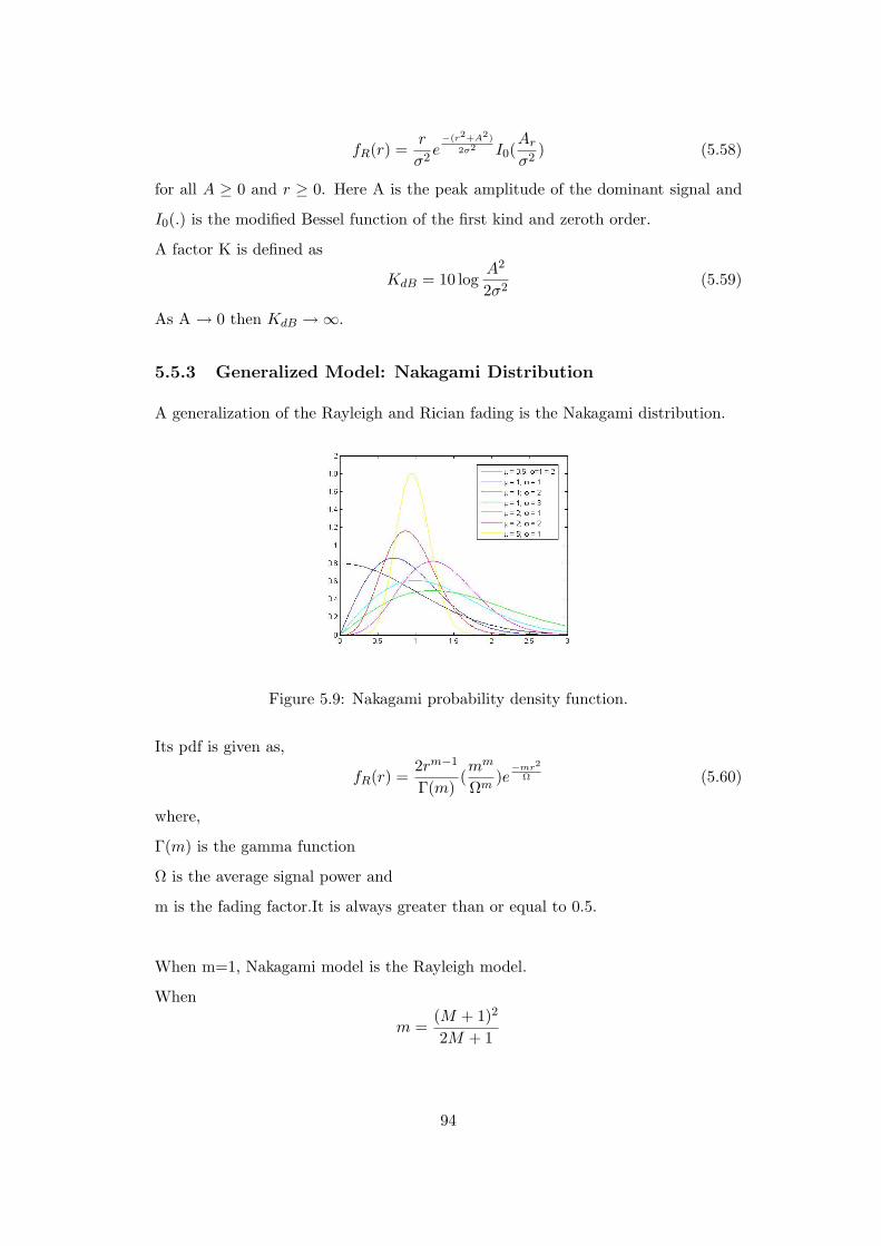
Figure 5.9: Nakagami probability density function.
Its pdf is given as,
fR(r) =2rm−1
Γ(m)(mm
Ωm)e
−mr2
Ω (5.60)
where,
Γ(m) is the gamma function
Ω is the average signal power and
m is the fading factor.It is always greater than or equal to 0.5.
When m=1, Nakagami model is the Rayleigh model.
When
m =(M + 1)2
2M + 1
94
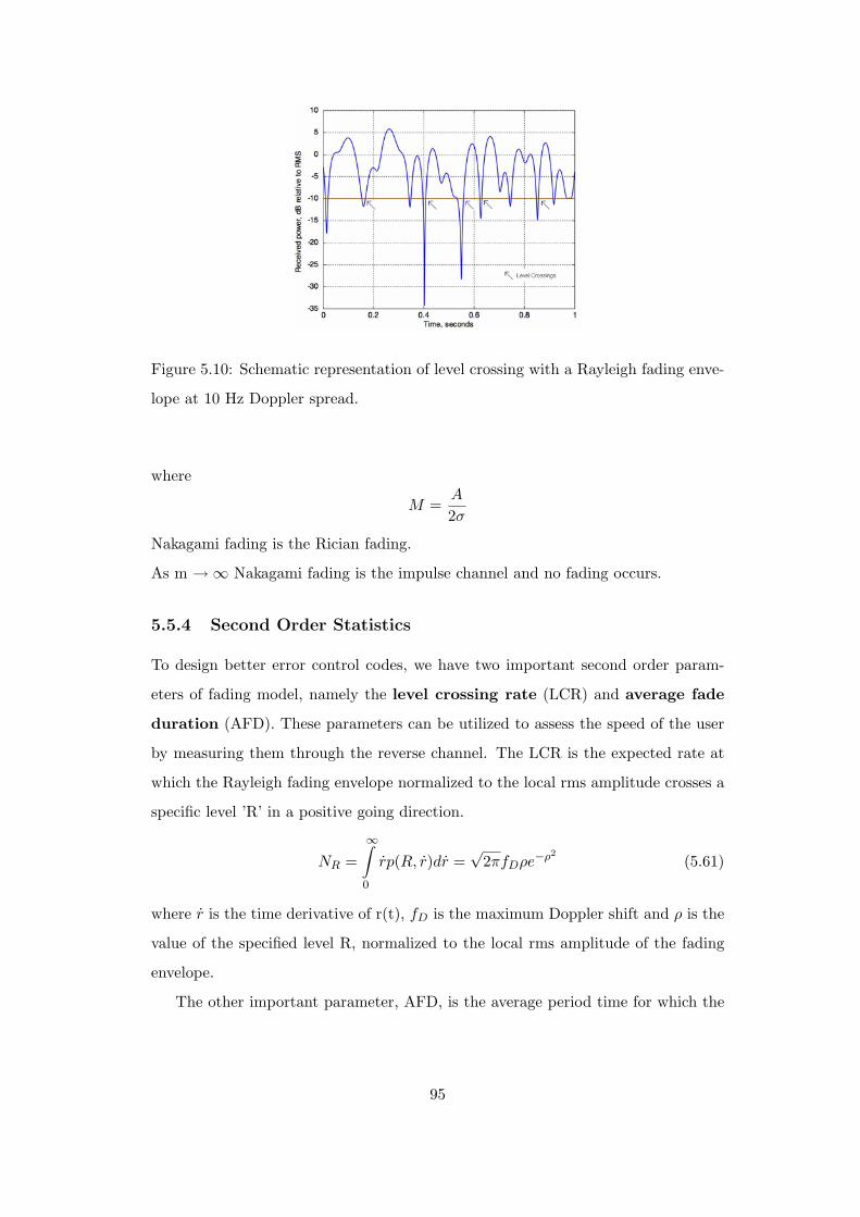
Figure 5.10: Schematic representation of level crossing with a Rayleigh fading enve-
lope at 10 Hz Doppler spread.
where
M =A
2σ
Nakagami fading is the Rician fading.
As m → ∞ Nakagami fading is the impulse channel and no fading occurs.
5.5.4 Second Order Statistics
To design better error control codes, we have two important second order param-
eters of fading model, namely the level crossing rate (LCR) and average fade
duration (AFD). These parameters can be utilized to assess the speed of the user
by measuring them through the reverse channel. The LCR is the expected rate at
which the Rayleigh fading envelope normalized to the local rms amplitude crosses a
specific level ’R’ in a positive going direction.
NR =∞∫0
rp(R, r)dr =√
2πfDρe−ρ2(5.61)
where r is the time derivative of r(t), fD is the maximum Doppler shift and ρ is the
value of the specified level R, normalized to the local rms amplitude of the fading
envelope.
The other important parameter, AFD, is the average period time for which the
95
receiver power is below a specified level R.
τ =1
NrPr(r ≤ R) (5.62)
As
Pr(r ≤ R) =R∫
0
p(r)dr = 1 − e−ρ2, (5.63)
therefore,
τ =1 − e−ρ2
√2πfDρe−ρ2
(5.64)
=e−ρ2 − 1√
2πfDρ. (5.65)
Apart from LCR, another parameter is fading rate, which is defined as the number of
times the signal envelope crosses the middle value (rm) in a positive going direction
per unit time. The average rate is expressed as
N(rm) =2v
λ. (5.66)
Another statistical parameter, sometimes used in the mobile communication, is
called as depth of fading. It is defined as the ratio between the minimum value
and the mean square value of the faded signal. Usually, an average value of 10% as
depth of fading gives a marginal fading scenario.
5.6 Simulation of Rayleigh Fading Models
5.6.1 Clarke’s Model: without Doppler Effect
In it, two independent Gaussian low pass noise sources are used to produce in-phase
and quadrature fading branches. This is the basic model and is useful for slow fading
channel. Also the Doppler effect is not accounted for.
5.6.2 Clarke and Gans’ Model: with Doppler Effect
In this model, the output of the Clarke’s model is passed through Doppler filter in
the RF or through two initial baseband Doppler filters for baseband processing as
shown in Figure 5.11. Here, the obtained Rayleigh output is flat faded signal but
not frequency selective.
96

Figure 5.11: Clarke and Gan’s model for Rayleigh fading generation using quadra-
ture amplitude modulation with (a) RF Doppler filter, and, (b) baseband Doppler
filter.
5.6.3 Rayleigh Simulator with Wide Range of Channel Conditions
To get a frequency selective output we have the following simulator through which
both the frequency selective and flat faded Rayleigh signal may be obtained. This
is achieved through varying the parameters ai and τi, as given in Figure 5.12.
5.6.4 Two-Ray Rayleigh Faded Model
The above model is, however, very complex and difficult to implement. So, we have
the two ray Rayleigh fading model which can be easily implemented in software as
shown in Figure 5.13.
hb(t) = α1ejφ1δ(t) + α2e
jφ2δ(t − τ) (5.67)
where α1 and α2 are independent Rayleigh distributed and φ1 and φ2 are indepen-
dent and uniformaly distributed over 0 to 2π. By varying τ it is possible to create
a wide range of frequency selective fading effects.
97
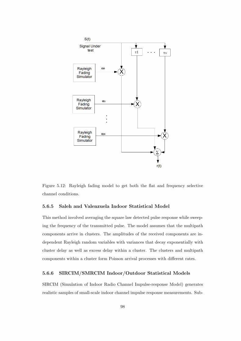
Figure 5.12: Rayleigh fading model to get both the flat and frequency selective
channel conditions.
5.6.5 Saleh and Valenzuela Indoor Statistical Model
This method involved averaging the square law detected pulse response while sweep-
ing the frequency of the transmitted pulse. The model assumes that the multipath
components arrive in clusters. The amplitudes of the received components are in-
dependent Rayleigh random variables with variances that decay exponentially with
cluster delay as well as excess delay within a cluster. The clusters and multipath
components within a cluster form Poisson arrival processes with different rates.
5.6.6 SIRCIM/SMRCIM Indoor/Outdoor Statistical Models
SIRCIM (Simulation of Indoor Radio Channel Impulse-response Model) generates
realistic samples of small-scale indoor channel impulse response measurements. Sub-
98

Figure 5.13: Two-ray Rayleigh fading model.
sequent work by Huang produced SMRCIM (Simulation of Mobile Radio Channel
Impulse-response Model), a similar program that generates small-scale urban cellu-
lar and micro-cellular channel impulse responses.
5.7 Conclusion
In this chapter, the main channel impairment, i.e., fading, has been introduced which
becomes so severe sometimes that even the large scale path loss becomes insignificant
in comparison to it. Some statistical propagation models have been presented based
on the fading characteristics. Mainly the frequency selective fading, fast fading and
deep fading can be considered the major obstruction from the channel severity view
point. Certain efficient signal processing techniques to mitigate these effects will be
discussed in Chapter 7.
5.8 References
1. T. S. Rappaport, Wireless Communications: Principles and Practice, 2nd ed.
Singapore: Pearson Education, Inc., 2002.
2. S. Haykin and M. Moher, Modern Wireless Communications. Singapore: Pear-
son Education, Inc., 2002.
3. J. W. Mark and W. Zhuang, Wireless Communications and Networking. New
Delhi: PHI, 2005.
99
4. K. Feher, Wireless Digital Communications: Modulation and Spread Spectrum
Applications. Upper Saddle River, NJ: Prentice Hall, 1995.
5. R. Blake, Wireless Communications Technology. Delmar, Singapore: Thom-
son Asia Pvt Ltd, 2004.
6. D. P. Agarwal and Q-A. Zeng, Introduction to Wireless and Mobile Systems.
Nelson, India: Thomson Learning, 2007.
100
Related Documents