CHAPTER 9 MULTIMEDIA STREAMING IN MOBILE WIRELESS NETWORKS SANJEEV VERMA Nokia Research Center Tampere, Finland MUHAMMAD MUKARRAM BIN TARIQ DocoMo Communication Laboratories USA, Inc. San Jose, California TAKESHI YOSHIMURA Multimedia Laboratories, NTT DoCoMo, Inc. Yokosuka, Kanagawa, Japan TAO WU Nokia Research Center Burlington, Massachusetts 9.1 INTRODUCTION Multimedia services, such as streaming applications, are growing in popularity with advances in compression technology, high-bandwidth storage devices, and high- speed access networks. Streaming services are generally used in applications like multimedia information and message retrieval, video on demand, and pay TV. Also, there has been growing popularity of portable devices, such as notebook com- puters, PDAs, and mobile phones in recent years. Now it is possible to provide very high-speed access to portable devices with emerging technologies like WLAN and 3G networks. For instance, emerging 3G wireless technologies provide data rates of 144 kbps for vehicular, 384 kbps for pedestrian, and 2 Mbps for indoor environ- ments [1,2]. Hence, it is now possible to enrich the end user’s experience by com- bining multimedia services [3,4] with mobile-specific services such as geographic positioning, user profiling, and mobile payment. One example of such service is “mobile cinema ticketing,” which uses geographic positioning and user-defined Content Networking in the Mobile Internet, Edited by Sudhir Dixit and Tao Wu ISBN 0-471-46618-2 Copyright # 2004 John Wiley & Sons, Inc.

MultimediaStreaming_bookchapter_proof
Aug 16, 2015
Welcome message from author
This document is posted to help you gain knowledge. Please leave a comment to let me know what you think about it! Share it to your friends and learn new things together.
Transcript
CHAPTER 9
MULTIMEDIA STREAMING IN MOBILEWIRELESS NETWORKS
SANJEEV VERMANokia Research CenterTampere, Finland
MUHAMMAD MUKARRAM BIN TARIQDocoMo Communication Laboratories USA, Inc.San Jose, California
TAKESHI YOSHIMURAMultimedia Laboratories, NTT DoCoMo, Inc.Yokosuka, Kanagawa, Japan
TAO WUNokia Research CenterBurlington, Massachusetts
9.1 INTRODUCTION
Multimedia services, such as streaming applications, are growing in popularity with
advances in compression technology, high-bandwidth storage devices, and high-
speed access networks. Streaming services are generally used in applications like
multimedia information and message retrieval, video on demand, and pay TV.
Also, there has been growing popularity of portable devices, such as notebook com-
puters, PDAs, and mobile phones in recent years. Now it is possible to provide very
high-speed access to portable devices with emerging technologies like WLAN and
3G networks. For instance, emerging 3G wireless technologies provide data rates of
144 kbps for vehicular, 384 kbps for pedestrian, and 2 Mbps for indoor environ-
ments [1,2]. Hence, it is now possible to enrich the end user’s experience by com-
bining multimedia services [3,4] with mobile-specific services such as geographic
positioning, user profiling, and mobile payment. One example of such service
is “mobile cinema ticketing,” which uses geographic positioning and user-defined
Content Networking in the Mobile Internet, Edited by Sudhir Dixit and Tao WuISBN 0-471-46618-2 Copyright # 2004 John Wiley & Sons, Inc.
preferences to offer a mobile user a selection of movies from nearby movie theatres.
A user views corresponding movie trailers through a streaming service before select-
ing a movie and purchasing a ticket.
Streaming services are services in which continuous video and audio data are
delivered to an end user. A multimedia streaming service consists of one or more
media streams. A multimedia streaming application may have both audio and
video components (e.g., news reviews, movie trailers) or it may have audio stream-
ing with visual presentation comprising still images and or graphics animations,
such as a quarterly Webcast of earnings by corporations. These applications are gen-
erally stored at a Web-based server and streamed to clients on request. Streaming
audiovideo clips are sufficiently large, which makes their transmission time
longer (several minutes or longer) than the acceptable playback latency. Hence,
downloading the entire audiovideo content before its playback is not an option.
The streaming audiovideo clips are played out while parts of the clips are being
received and decoded. This is the biggest advantage of streaming service, since a
user is able to see video soon after downloading begins.
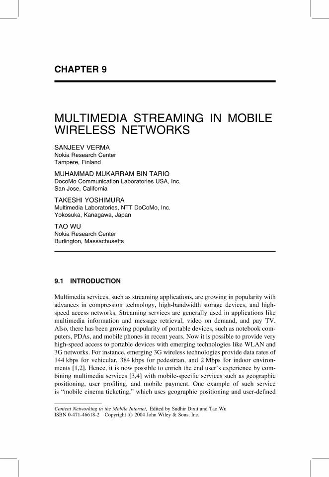
Figure 9.1 illustrates a general architecture for providing streaming services [5].
The multimedia content for streaming services is created from one or more media
sources (videocamera, microphone, etc). It can also be created synthetically
without using any natural media source. Examples of synthetically generated multi-
media contents are computer-generated graphics and digitally generated music.
Typically, the storage space required for raw multimedia content can be huge.
The multimedia content is digitally edited and compressed in order to provide attrac-
tive multimedia retrieval services over low-speed modem connections. The edited
Figure 9.1 A general architecture designed to provide streaming services.
276 MULTIMEDIA STREAMING IN MOBILE WIRELESS NETWORKS
and compressed multimedia clips are then stored in storage devices at the server. On
receiving a request from the client, the streaming server retrieves the compressed
multimedia clip from storage devices and the application layer QoS module
adapts the multimedia stream based on the QoS feedback at the application layer.
After adaptation at the application layer, transport protocols packetize the com-
pressed multimedia clips and send them over the Internet. The packets may suffer
losses and accumulate delay jitter while traversing the Internet. To further
improve the QoS, continuous media distribution services (e.g., caching) may be
deployed in the Internet. The successfully delivered media packets are decom-
pressed and decoded at the client end. Compensation or playout buffers are deployed
at the terminal end to mitigate the impact of delay jitter in the Internet and to achieve
seamless QoS. Clients also use media synchronization mechanisms to achieve syn-
chronization across different media streams, for example, between audio and video
streams.
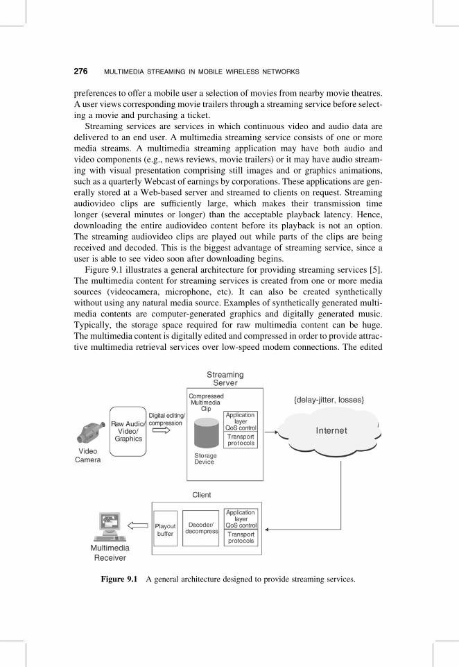
There are several challenges in providing streaming services in wireless environ-
ments due to some issues that are specific to these environments (see Fig. 9.2). For
example, wireless terminals typically have power constraints due to battery power.
Also, they have limited buffering and processing power available due to size and
power constraints. In addition, wireless environments are very harsh. The character-
istics of a wireless channel have a very unpredictable time-varying behavior due to
several factors such as interference, multipath fading, and atmospheric conditions.
This results in more delay jitter, more delay, and higher error rates, compared to
that in wired networks. Moreover, the mobility or the movement of a mobile user
from one cell to another cell introduces additional uncertainty. The movement trig-
gers a handoff mechanism to minimize interruption to an ongoing session. The wire-
less channel characteristics may be entirely different in a new cell after handoff. The
access point (typically a basestation) of the mobile host to the wired network also
changes after the handoff. This results in the establishment of entirely new route
in the wired network. The new route in the fixed network may have very different
path characteristics. This problem becomes even more severe as wireless networks
Limited Resources
Mobile Terminals Wireless Environments
Harsh Environments•Power constraints•Limited storage•Limited processing
•High error rate•Large and variable delay•Expensive spectrum
Figure 9.2 Constraints in wireless environments.
9.1 INTRODUCTION 277

are being implemented using smaller cell sizes (microcell) to allow higher system
capacity. Microcell implementation results in rapid handoff rates, causing even
wider variation in path characteristics. These issues have some implications in
providing streaming services in mobile environments. Streaming architecture in
wireless/mobile environments should ensure minimum processing at the mobile
terminal end. For instance, a typical approach used by streaming applications
regarding QoS adaptations at the application layer may not be suitable in wireless
environments. Adaptation at the application layer involves a lot of end-to-end sig-
naling, which may eat away precious resources at the terminal end. Also, it is
very difficult for mobile terminals with very limited processing and buffering capa-
bility to adapt at the application layer. The wireless network should have built-in
networkwide mechanisms to minimize the resource and processing requirements
at the mobile terminals. The overall design goal of wireless access architecture
should be to “make networks friendly to applications” rather than “make appli-
cations friendly to networks.”
In the remainder of this chapter, we will describe the different components and
protocols that are constituents of the streaming architecture. First, we go over
various QoS issues to support streaming services in general. We then give an over-
view of various codecs and media types that constitute an important component of
multimedia streaming architecture. Next, we describe a general architecture to
implement streaming services in mobile environments. We first review the different
architectural components that support these services in wireless/mobile environ-
ments. In subsequent sections, we give an overview of key protocols and languages
used for streaming multimedia delivery and provide an overview of their working
and example usage. We then describe packet-switched streaming service architec-
ture developed by 3GPP (referred as 3GPP-PSS) since it is the most mature stan-
dardization activity in this field. Most likely, the 3GPP2 architectural solution
will also be on similar lines. Next, we discuss research issues and related work in
providing multimedia services in mobile and wireless environments. Finally, we
summarize and look into the future trends in supporting multimedia services in
broadband wireless access networks.
9.2 QOS ISSUES FOR STREAMING APPLICATIONS
Streaming applications are real-time noninteractive applications. Also, they involve
one-way delivery of streaming data from the server to the client. Because of their
real-time nature, these applications typically have bandwidth, delay jitter, and
loss requirements. We first discuss the QoS parameters that are specifically very
important for the streaming applications and then the QoS control mechanisms at
application and lower layers.
Delay jitter [6] is particularly important for these applications. The delay jitter
bound for a session is calculated as the difference between the largest and smallest
delays incurred by packets belonging to the session. A client (receiver) should
choose playback instants so that, when it is ready to output the information
contained in the packet, the packet has already arrived. If the delay jitter over a
278 MULTIMEDIA STREAMING IN MOBILE WIRELESS NETWORKS
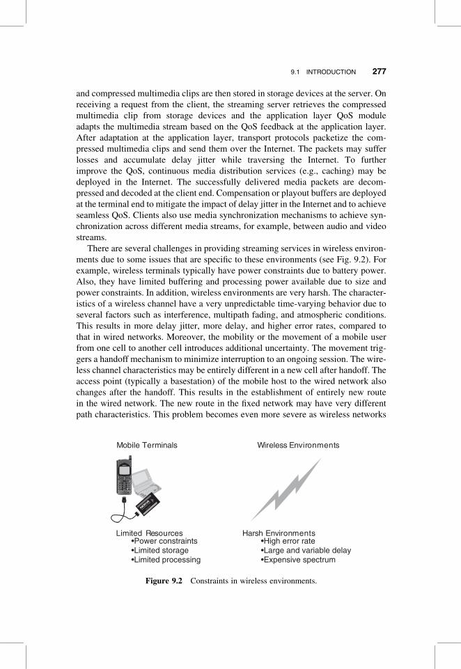
network connection is bounded, the receiver can eliminate delay variations in the
network by delay jitter bound in a playout or compensation buffer (see Fig. 9.3).
Subsequent packets are then scheduled for transmission according to the rate at
which they are generated at the sender. The packets, which arrive earlier than
their scheduled playout time, wait in the playout buffer. Thus, the larger the delay
jitter bound, the larger the playout buffer required at the receiver to maintain con-
stant quality. For a given delay jitter bound, the required playout buffer size is the
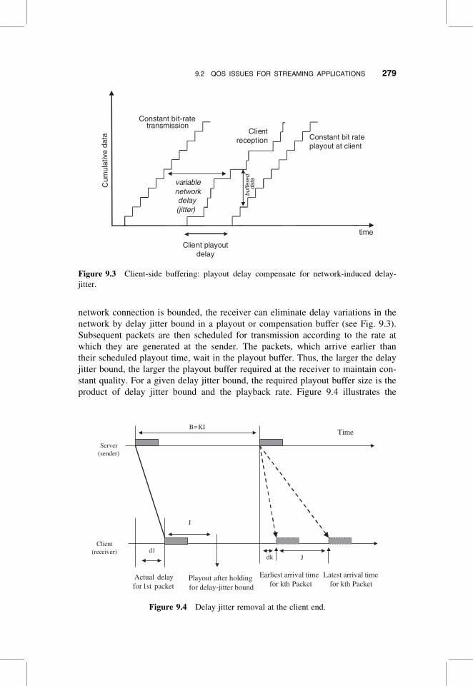
product of delay jitter bound and the playback rate. Figure 9.4 illustrates the
Constant bit-rate
Cum
ulat
ive
data
time
variablenetworkdelay(jitter)
Clientreception
Client playoutdelay
buffe
red
data
Constant bit rateplayout at client
transmission
Figure 9.3 Client-side buffering: playout delay compensate for network-induced delay-
jitter.
TimeB=KI
Playout after holdingfor delay-jitter bound
Actual delay for 1st packet
Earliest arrival time for kth Packet
Latest arrival time for kth Packet
d1
J
Jdk
Server(sender)
Client(receiver)
Figure 9.4 Delay jitter removal at the client end.
9.2 QOS ISSUES FOR STREAMING APPLICATIONS 279
removal of delay jitter at a client. Although the output rate of the server could vary
with time, for simplicity we assume that the server is generating packets at the con-
stant rate with equal spacing every I seconds. The receiver delays the first packet by
the delay jitter bound J and then plays out packets with the same spacing as they are
generated. Suppose that the first packet arrives at the receiver d1 seconds after the
transmission and is further delayed by an amount equal to the delay jitter bound J
in playout buffer. The Kth packet is generated after B ¼ KI seconds, and this
packet will incur a delay between dk (fixed delay, mainly propagation delay)
seconds and (dkþ J) seconds. Since the client plays back the packets with the
same spacing as when they were generated, the Kth packet will be scheduled for
playout at (d1 þ Jþ B) seconds. Since d1 . ¼ dk, the latest arrival of the kth
packet, (dkþ Jþ B) is guaranteed to be before the scheduled time. Thus by delaying
packets in the playout buffer for delay jitter bound, the receiver can eliminate jitter
in the arrival stream, and guarantee that a packet has already arrived by the time the
client is ready to play it.
Note that the playout buffer is useful only to absorb short-term delay
variations. The more data are initially buffered, the wider are the variations that
can be absorbed, but higher startup playback latency is experienced at the client
end. The maximum allowable buffering is determined by the acceptable delay
latency.
Another important QoS parameter for a streaming application is the error rate.
Although streaming applications can tolerate some loss, the error rate beyond a
threshold can degrade the quality of the delivered streaming data significantly. To
maintain reasonably good quality of played-back stream, a proper error control
mechanism is needed to recover packets before their scheduled playback time.
The well-known techniques to minimize error for streaming traffic are FEC, inter-
leaving, and redundant retransmissions. In addition, the lost packets can be recov-
ered through limited retransmissions. This necessitates buffering at the client end
to allow for retransmissions.
Now we look into the specific QoS control mechanisms at the application and
lower layers to achieve the QoS needs of multimedia streaming applications.
9.2.1 Application Layer QoS Control
The goal of the application layer QoS control is to adapt at the application layer in
order to provide acceptable quality streaming service to the end user in the presence
of packet loss and congestion in the network. We note here that the Internet in its
current form is a best-effort network and does not provide networkwide QoS
support. Thus the available bandwidth is not known in advance and varies with
time. The packets may suffer variable delay and come out of order at the client
end. Clients need to adapt at the application layer in order to receive good-quality
streaming service. The application layer QoS control techniques include end-
to-end congestion and error control. These techniques are employed by the end
systems and do not assume any support from the network.
280 MULTIMEDIA STREAMING IN MOBILE WIRELESS NETWORKS

9.2.1.1 Congestion Control and Quality AdaptationThe Internet in its very rudimentary form provides a transport network that delivers
packets from one point to another. It provides a shared environment, and its stability
depends on the end systems implementing appropriate congestion control algor-
ithms. The end-to-end congestion control algorithms help to reduce packet loss
and delay in the network. Unfortunately, it is not possible for streaming applications
to implement end-to-end congestion control algorithms since stored multimedia
applications typically have intrinsic transmission rates. Streaming applications are
rate-based and typically transmit data with a near-constant rate or loosely adjust
their transmission rate on long timescales since the required rate for being well
behaved is not compatible with their nature. For streaming applications, congestion
control takes the form of rate control that attempts to minimize the possibility of con-
gestion by matching the rate of streaming media to the available network bandwidth.
A vast majority of the Internet applications implement TCP-based congestion
control that uses the additive increase, multiplicative decrease (AIMD) algorithm.
Under this algorithm, the transmission rate is linearly increased until a loss of
packet signals congestion and a multiplicative decrease is performed. TCP, as it
is, is not appropriate for delay-sensitive applications such as streaming. To ensure
fairness and efficient utilization of network resources, rate control algorithms for
streaming applications should be “TCP-friendly” [7–9]. This means that a stream-
ing application sharing the same path with a TCP flow should obtain the same
average throughput during a session. A number of model-based TCP-friendly rate
control mechanisms [10] have been proposed for streaming applications. These
mechanisms are based on the mathematical models that relate the throughput of a
typical TCP connection to the network parameters [7]:
l ¼1:22 � MTU
RTT �ffiffiffiffi
pp (9:1)
where
l ¼ throughput of a TCP connection
MTU ¼ maximum transmission unit is the maximum packet size used by the
connection
RTT ¼ Roundtrip time for the connection
p ¼ packet loss experienced by the connection
Under the model-based approach, the streaming server uses Equation (9.1) to deter-
mine the sending rate of the streamed media to behave in a TCP-friendly manner.
The source basically regulates the rate of the streamed media according to the feed-
back information of the network. This can be used for both unicast and multicast
scenarios. However, a source-rate-based control scheme is not suitable in hetero-
geneous network environments, where receivers have heterogeneous network
capacity and processing power.
Receiver-based rate control [11,12] has been found to be better rate control mech-
anism in heterogeneous network environments. Under this mechanism, receivers
9.2 QOS ISSUES FOR STREAMING APPLICATIONS 281

regulate the receiving rate of streaming media by adding or dropping channels
without any rate regulation from the source end. This is targeted toward scenarios
where the source multicasts layered video with several layers. The basic scheme
works as follows:
1. When no congestion is detected, a receiver joins or adds a layer or channel that
results in increase of its receiving rate. If addition of a channel does not cause
any congestion then join experiment is deemed successful. Otherwise, the
receiver drops the added layer or channel.
2. If congestion is detected, the receiver drops the low-priority layer or channel
(enhancement channel).
Alternatively, an architecture may use both source and receiver-based control mech-
anisms [13] in which receivers regulate the receiving rate of streaming media by
adding or dropping channels, while the sender also adjusts the transmission rate
of each channel according to the feedback from the receivers.
One of the main challenges in delivering streaming media to a client is to adjust
with variations in network bandwidth while delivering acceptable quality streaming
media to the receiver. As discussed before, short-term variations in bandwidth can
be handled by providing playout or compensation buffer at the receiver. When avail-
able bandwidth is more than the playback rate at the receiver, the spare data are
stored in the playout buffer and when the available bandwidth is less than that
required to maintain the constant quality then the deficit is supplied by the spare
data in the playout buffer (see Fig. 9.5). However, the bandwidth variations for a
long-lived session can be very large and random. This may cause the client’s
buffer to either underflow or overflow. The buffer underflow is particularly undesir-
able since it causes interruption of service at the client’s end. Rate control
su
Spare data stored inplayout buffer
pplied fromuffer
Available bandwidthfrom network
Playbackrate
Transmission rate
raining Phase
Ban
dwid
th
Filling Phase D
Time
Deficit pl t bayou
Figure 9.5 Short-term quality adaptation at client.
282 MULTIMEDIA STREAMING IN MOBILE WIRELESS NETWORKS
mechanisms discussed in preceding paragraphs are one way to tackle quality adap-
tation due to long-term variations in network bandwidth. Alternative mechanisms
are adaptive encoding and switching between multiple encoded versions. Under
adaptive encoding mechanism, the server adjusts the resolution of encoding by
doing requantization based on the network feedback. However, this task is very
CPU-intensive and is not scalable to large number of clients. Also, once the stream-
ing data are compressed and stored, encoders cannot change the output rate over a
wide range. In another alternative scheme, a server maintains several versions of
media streams, each with different qualities. As available bandwidth in the
network changes, the server dynamically switches between low- and high-quality
media streams as appropriate.
Hence, quality adaptation under short-term variations in bandwidth is achieved
through the playout/compensation buffer at client end and quality adaptation
under long term, and wide variations in bandwidth are achieved through appropriate
rate control mechanisms at both client and server ends.
9.2.1.2 Error ControlAs previously mentioned, streaming media can survive as long as the error rate
remains within an acceptable limit. The error rate is particularly important in wire-
less environments that have very high error rates. Moreover, errors tend to happen in
bursts in these environments. Well-known techniques to minimize the error for
streaming traffic are FEC (forward error correction), error-resilient encoding,
error-concealment, and retransmissions. The FEC technique adds redundant infor-
mation to the original packet in order to recover the packet in the presence of
error. Error-resilient encoding is a preventive technique that enhances the robustness
of streaming media in the presence of packet loss. The well-known error-resilient
encoding schemes are resynchronization marking, data partitioning, and data recov-
ery. These are particularly effective in wireless environments. Another promising
error-resilient encoding scheme is multiple description coding (MDC) [14], where
raw video data are encoded into a number of streams (or descriptions): each descrip-
tion provides an acceptable quality. If a client gets only one description, it should
also be able to reconstruct video with reasonably good quality. However, the recei-
ver can construct better-quality video if it gets more than one description. Error con-
cealment techniques, on the other hand, adopt a reactive approach and aim to
conceal lost packets and make the presentation less displeasing to human eyes.
Packet retransmission techniques [15] are considered very effective in wireless
environments because of bursty nature of wireless channels. In general, packet
retransmission is not deemed very suitable for real-time applications such as
video because of retransmission delay. However, the retransmission may be
allowed, especially for high-priority packets, if there is sufficient delay until the
scheduled playback time of the packet considered. Clients may request the retrans-
missions of only those high-priority packets that have sufficient retransmission delay
budget. We explain this concept as follows. For simplicity, we assume that the
9.2 QOS ISSUES FOR STREAMING APPLICATIONS 283
server is generating packets at a constant frame rate (say, every T seconds). We
introduce the following notations:
Pn ¼ playback time of the nth packet
Tn ¼ arrival time of the nth packet
T ¼ interframe time
RTT ¼ estimated roundtrip time
Td ¼ loss detection delay
Tr ¼ retransmission delay
Tc ¼ current time
Thus the scheduled time of the kth frame can be given by (P0 þ kT), where P0 is the
playback time of the 0th frame. Now, if the current time is Tc, the delay budget
before the scheduled playback time of the kth packet can be given by
Delay budget ¼ (P0 þ kT) � Tc (9:2)
This delay budget should be sufficient to allow retransmission of the frame from the
server taking into account loss detection delay, estimated roundtrip delay, and
retransmission time. The client should send the retransmission request to the
server only if the following condition is satisfied:
Td þ RTT þ Tr � delay budget (9:3)
The objective here is to avoid unnecessary retransmissions that will not arrive in
time for display.
9.2.2 Network Layer QoS Control
The previous discussions on QoS control at the application layer for streaming ser-
vices assume no support from network whatsoever. The QoS support at the network
layer and below complements the QoS mechanisms at application layer and reduces
the signaling and processing load at higher layers.
Providing QoS in the Internet is inherently a difficult problem due to its connection-
less nature. However, a number of proposals have been made in IETF to provide some
sort of QoS support in the Internet. Currently, there are two approaches, notably Inte-
grated Services (IntServ[16]) and Differentiated Services (DiffServ[17]), standardized
by IETF to provide QoS support in the Internet. The IntServ model provides per flow
QoS guarantees. A flow is defined as a stream of packets between two end nodes with
the same tuple of source address, destination address, source port number, and destina-
tion port number. The IntServ model consists of four functional blocks: end-to-end sig-
naling protocol, call admission control at the edge, packet classifier at the edge, and
packet scheduler at every network element in the path. RSVP [18] is the proposed sig-
naling protocol to take the reservation requests to all the routers in the path. Underlying
284 MULTIMEDIA STREAMING IN MOBILE WIRELESS NETWORKS
IP routing protocols determine the path, and RSVP signaling is used to reserve
resources along the selected path. Keeping in mind the dynamic nature of IP routing
protocols, the soft-state approach is utilized to reserve resources. Though IntServ pro-
vides excellent QoS model, it suffers from scalability problem. Network elements need
to maintain a per flow state to provide per flow QoS guarantees. This can introduce
scalability problems, particularly in backbone networks that support tens of thousands
of flows. The DiffServ QoS model is another approach that provides scalable solution
and does not require any signaling support. Unlike IntServ model, this model does not
provide per flow QoS guarantees. Under this model, routers simply implement a suite
of prioritylike scheduling and buffering mechanisms and apply them to IP packets
based on the DS-field in the packet headers. The service that an individual flow gets
is determined by the traffic characteristics of the other flows (cross-traffic) sharing
the same service class. The lack of networkwide control implies that, on overload in
a given service class, all flows in that class suffer a degradation of service. DiffServ
tries to give soft QoS guarantees to flows by using a combination of provisioning,
service-level agreements, and per hop behavior implementations. For this purpose,
networkwide mechanisms are deployed in the network. Bandwidth broker (BB) is
one approach to do resource provisioning within a DiffServ domain. BB is the resource
manager within the DiffServ domain that keeps track of available resources and
topology information for a domain. BB uses COPS (common open policy service)
protocol [19] to interact with routers inside the domain.
9.3 STREAMING MEDIA CODECS
Standardized video coding and decoding methods, such as H.263 by ITU-T and MPEG-
4 by ISO, are expected to be supported by a wide range of mobile terminals and net-
works. For audio-only content, MPEG-4 AAC is an appealing candidate for its superior
coding efficiency, while MP3 is also likely to be supported because of its popularity on
the Internet. Some mobile terminals may also support proprietary codecs and file
formats, such as those developed by Apple Computer, Microsoft, and Real Networks.
9.3.1 Video Compression
Video compression in mobile networks is usually lossy compression that exploits
temporal and spatial redundancy within the video streams. Specifically, motion esti-
mation and compensation are widely used between consecutive video frames to
reduce temporal redundancy. Within a frame, block-based transforms such as
DCT (discrete-cosine transform) are performed to reduce spatial redundancy. In
MPEG, for example, one can encode a video frame into one of the following
types of encoded pictures [20]:
. I-picture (I ¼ intraframe). I-pictures are encoded using intraframe information
only, independently of other frames. In other words, I-pictures exploit spatial
redundancy only.
9.3 STREAMING MEDIA CODECS 285
. P-picture (P ¼ interframe prediction). P-pictures are encoded using the most
recent-I-picture or P-picture as a reference.
. B-picture (B ¼ bidirectional prediction). B-pictures are encoded using P-pic-
tures and/or I-pictures both in the past and in the future as references.
A video stream composed of I-pictures allows for flexible random access and
high editability, but its compression ratio is relatively poor. P-pictures and B-pic-
tures substantially improve compression efficiency at the cost of increased manipu-
lation difficulty (random access, editability, etc.) and in the case of B-pictures,
coding delay. Hence, an MPEG video stream often consists of a sequence of
pictures of all three types (e.g., I B B P B B P B B I B) to strike a good balance
among different aspects of performance and usability. In addition, MPEG-4 also
allows encoding of arbitrarily shaped objects in order to provide content-based
interactivity [21].
The mobile environment that we consider in this chapter brings some specific
requirements for video compression. For example, wireless channel errors can
lead to loss of synchronization because video encoders often uses variable-length
coding (VLC), and forward error correction (FEC) codes are not very effective in
correcting burst errors. Toward this end, error resilience and concealment tech-
niques that minimize the effect of channel errors are important in providing graceful
service degradation [22]. Furthermore, many mobile terminals have limited CPU,
memory, and battery power resources; thus controlling decoder complexity is
important for these terminals.
9.3.2 Audio Compression
Besides the speech codec used for voice services, general audio compression is
needed for high-quality audio services such as music delivery. General audio
coders typically generate higher bit rates than do speech coders since they
cannot rely on a specific audio production model as speech coders do with the
human vocal tract model. Additionally, while speech coder’s emphasis is intellig-
ibility, audio codec may need to provide higher signal fidelity in streaming media
services.
In high bit rate, an audio codec strives to preserve the original signal
waveform [23]. Higher compression can be achieved by taking advantage of the
human auditory model so that the signal components that the human ears are not
sensitive to can be compressed. More details on these techniques can be found in,
for example, the article by Poll [23].
9.3.3 Codecs Used in 3GPP
As an example, Table 9.1 lists required or recommended decoders in 3GPP [24].
Figure 9.6 illustrates general client functional components for streaming media
service in 3GPP [24].
286 MULTIMEDIA STREAMING IN MOBILE WIRELESS NETWORKS

TABLE 9.1 Codec Standards Used in 3GPP
Services Decoder Requirements or Recommendations
Speech AMR
Audio MPEG-4 AAC low complexity
Synthetic audio Scalable polyphony MIDI
Video H.263 profile 0 level 10 mandatory; MPEG-4 visual simple profile
optional
Still images JPEG
Bitmap graphics GIF, PNG
Vector graphics SVG Tiny profile
Figure 9.6 Functional components of a 3GPP packet-switched streaming service (PSS) client.
9.3 STREAMING MEDIA CODECS 287

9.4 END-TO-END ARCHITECTURE DESIGNED TO PROVIDESTREAMING SERVICES IN WIRELESS ENVIRONMENTS
Streaming multimedia is characterized by an application rendering audio, video, or
other media in a continuous way while part of the media is still being transmitted to
the application over a data network. Streaming multimedia is a little different from
conversational multimedia, which involves (usually bidirectional) conversation
between multiple parties. Although the type of the media (media encoding) used
for both streaming and conversational multimedia communication may be the
same, conversational multimedia usually has more stringent requirements on end-
to-end delay between the parties. Also, streaming multimedia is usually a client
server application and the media usually flow in only one direction (from server
to the client), whereas conversational multimedia, such as interactive videoconfer-
encing, is usually peer-to-peer, and the media (often) flow among all peers. If you
feel confused by this description, don’t worry; later in the chapter we will describe
streaming multimedia in more detail.
In previous sections we saw how streaming media applications process (through
decoding, error correction, buffering and scheduling) media data to compensate for
delay jitter and packet loss incurred over the network and ensure a smooth rendering.
Here we will discuss important logical components needed to enable streaming
service in mobile or wireless networks and the interrelationships between these
logical components required to form a complete streaming multimedia delivery
system. Our main focus is packet-based streaming systems. We will start with a dis-
cussion on logical layout and components for such a system. In subsequent sections,
we will shift focus to different protocols and languages used for streaming multime-
dia delivery and provide an overview of their working and example usage.
9.4.1 Logical Streaming Multimedia Architecture
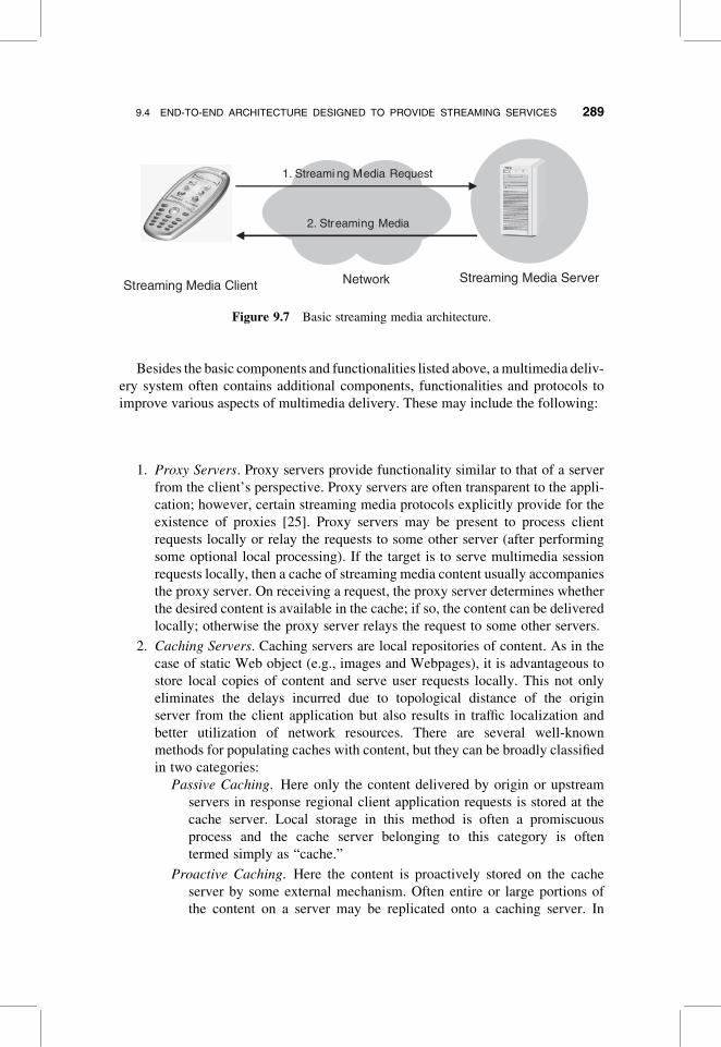
Streaming multimedia architecture (Fig. 9.7) consists of following basic components:
1. A streaming server that sends media as a continuous stream over a data
network. The server is often referred to as the origin server, to distinguish
it from intermediary (proxy or caching) servers.
2. A data network that transports media from the server to the client application.
3. A client application capable of receiving, processing and rendering continuous
stream of media in a smooth manner.
4. Protocols that are understood amongst the componentsing and allow them to
talk with each other. The protocols provide various functionalities, including
allowing the client to establish a streaming multimedia session with the server,
facilitating delivery of media from the server to the network and from the
network to the client, understanding the content of media stream for correct
processing at the client application (encoding and packaging), and allowing
interaction with the servers to manipulate the media streams.
288 MULTIMEDIA STREAMING IN MOBILE WIRELESS NETWORKS
Besides the basic components and functionalities listed above, a multimedia deliv-
ery system often contains additional components, functionalities and protocols to
improve various aspects of multimedia delivery. These may include the following:
1. Proxy Servers. Proxy servers provide functionality similar to that of a server
from the client’s perspective. Proxy servers are often transparent to the appli-
cation; however, certain streaming media protocols explicitly provide for the
existence of proxies [25]. Proxy servers may be present to process client
requests locally or relay the requests to some other server (after performing
some optional local processing). If the target is to serve multimedia session
requests locally, then a cache of streaming media content usually accompanies
the proxy server. On receiving a request, the proxy server determines whether
the desired content is available in the cache; if so, the content can be delivered
locally; otherwise the proxy server relays the request to some other servers.
2. Caching Servers. Caching servers are local repositories of content. As in the
case of static Web object (e.g., images and Webpages), it is advantageous to
store local copies of content and serve user requests locally. This not only
eliminates the delays incurred due to topological distance of the origin
server from the client application but also results in traffic localization and
better utilization of network resources. There are several well-known
methods for populating caches with content, but they can be broadly classified
in two categories:
Passive Caching. Here only the content delivered by origin or upstream
servers in response regional client application requests is stored at the
cache server. Local storage in this method is often a promiscuous
process and the cache server belonging to this category is often
termed simply as “cache.”
Proactive Caching. Here the content is proactively stored on the cache
server by some external mechanism. Often entire or large portions of
the content on a server may be replicated onto a caching server. In
Streaming Media ClientStreaming Media ServerNetwork
1. Streami ng Media Request
2. Streaming Media
Figure 9.7 Basic streaming media architecture.
9.4 END-TO-END ARCHITECTURE DESIGNED TO PROVIDE STREAMING SERVICES 289

this case the term surrogate server is sometimes used for the caching
server.
3. Additional Protocols. Additional protocols may include
Protocols for capability exchange between the client application and server,
so as to allow the server to transmit appropriate data.
Protocols for QoS feedback from client application to the server, enabling
the server to adapt the transmission (if possible).
Protocols and languages for (time and space) synchronization of multiple
multimedia streams.
Protocols and mechanisms for request routing to best available surrogate or
caching for a given client request. We will not discuss request routing
any further in this chapter. An overview of a multitude of request
routing methods can be found in the report by Barbir et al. [26].
4. Other Miscellaneous Components. A real-life deployment of a streaming mul-
timedia delivery system will rely on more than just the abovementioned com-
ponents (see example components in Fig. 9.8). Functionalities such as
authentication, authorization and accounting (AAA) often require additional
architectural support. Similarly, ensuring digital rights management (DRM)
may require additional functionality from client application and also from
the server and the content creation process. In certain scenarios dedicated
components may be present to provide QoS adaptation and feedback.
Standards for streaming media consist of a wide array of protocols, description
languages, and media coding techniques. These standards have been developed
and standardized at various standardization organizations, such as, Internet Engin-
eering Task Force IETF, ISO, Third-Generation Partnership Project, and World
Wide Web Consortium (W3C).
Network
Streaming Media Negotiation
Streaming Media
Streaming Media Server
Streaming Media Proxy Caches
Caches
Proxy based
Request Redirection to
appropriate servers in CDN
setup
QoS and other feedbackStreaming
Media Client
Figure 9.8 Some components of a typical streaming media architecture.
290 MULTIMEDIA STREAMING IN MOBILE WIRELESS NETWORKS

9.5 PROTOCOLS FOR STREAMING MEDIA
A streaming multimedia delivery system involves a number of protocols (see
Fig. 9.9) to deal with the different aspects of streaming media. The protocols
provide a common dialect through which different components in the architecture
can talk with each other. These protocols can be classified in two broad categories:
(1) session control and (2) media transport protocols. In most contemporary multi-
media streaming setups, separate logical channels are used for session control and
media transport. In some cases, however, most notably HTTP and RTSP tunneling,
the same logical channel is used for both session control and media transport. Con-
sequently, certain protocols provide functionalities that span more than one aspect of
multimedia streaming, and we cannot draw a hard boundary. We will discuss these
as well, but let’s first see what functionalities are expected out of the two main cat-
egories of the protocols.
9.5.1 Protocols and Languages for Streaming Media Session Control
Streaming multimedia often have a notion of (prolonged) association between
multiple components, for example, between the client application and the server;
this association is termed a session.
Client
Media Server
WebServer
HTTP GET
Session Descript ion(SDP)
SETUP
PLAY
PAUSE
CLOSE
RTP AudioRTP Video
RTCP
RTSP signaling
RTSP signaling
Figure 9.9 Protocols used in a typical streaming session.
9.5 PROTOCOLS FOR STREAMING MEDIA 291
Session control and establishment usually includes identifying the parties (the
client and server applications) involved in the session and the agreement or the
announcement of different session parameters. For IP-based environments the
parties are often identified by their transport layer address (IP address and port
number). Multimedia streaming sessions often have a rich set of parameters, the
most important of which are the types of encoding of media that will later flow
from the sender (server application) to the recipient (client application). These par-
ameters allow the application on the recipient to process and render the media cor-
rectly. Different session control protocols provide varying degrees of functionality,
but all of them provide minimal functionality for basic session control: session
setup, teardown and establishment of other session parameters.
Examples of session control protocols include the real-time streaming control
protocol (RTSP) [25], the session announcement protocol (SAP) [27], the session
description protocol (SDP) [28], the session initiation protocol (SIP) [29], and
ITU-T’s H.323 [30].
RTSP is the dominant session control protocol for client–server streaming multi-
media application and is defined in RFC 2326 [25]. In this section you will find a
brief tutorial on RTSP and its use; however, it is by no means a complete description
of RTSP. In the following section we will describe RTSP in detail and briefly over-
view the other protocols in this realm.
9.5.1.1 Real-Time Streaming ProtocolRTSP is an application-level client–server protocol that provides the functionality
needed to establish and control a streaming session. The session may comprise
one or more streams, which are described using a presentation description (using
expressions such as SMIL or SDP). Once a session is established, RTSP provides
methods for controlling the streams, such as, VCR-like forward, rewind,
pause, and record methods. RTSP primarily provides functionalities to retrieve
data from the server and invite a server to a conference, and it is a transaction-
oriented, request–response protocol like HTTP. However, there are a number of
differences:
. RTSP servers are required to maintain state between most transactions, unlike
in HTTP, in which the servers are mostly stateless.
. RTSP defines new methods and a protocol identifier.
. In RTSP, the server side may issue some requests as well, unlike the in case
HTTP, where the client always makes the request and the server sends back
a response.
. In RTSP, the data are carried mostly out of band, on a separate data channel
such as RTP. In HTTP, the data are carried in payload of HTTP (response)
messages.
. RTSP uses absolute resource identifiers (request URI); this is to eliminate the
problems caused due to usage of relative URLs in earlier versions of HTTP.
292 MULTIMEDIA STREAMING IN MOBILE WIRELESS NETWORKS
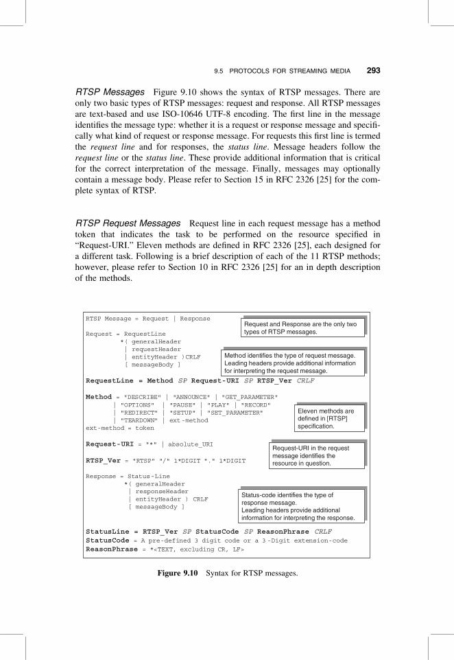
RTSP Messages Figure 9.10 shows the syntax of RTSP messages. There are
only two basic types of RTSP messages: request and response. All RTSP messages
are text-based and use ISO-10646 UTF-8 encoding. The first line in the message
identifies the message type: whether it is a request or response message and specifi-
cally what kind of request or response message. For requests this first line is termed
the request line and for responses, the status line. Message headers follow the
request line or the status line. These provide additional information that is critical
for the correct interpretation of the message. Finally, messages may optionally
contain a message body. Please refer to Section 15 in RFC 2326 [25] for the com-
plete syntax of RTSP.
RTSP Request Messages Request line in each request message has a method
token that indicates the task to be performed on the resource specified in
“Request-URI.” Eleven methods are defined in RFC 2326 [25], each designed for
a different task. Following is a brief description of each of the 11 RTSP methods;
however, please refer to Section 10 in RFC 2326 [25] for an in depth description
of the methods.
RTSP Message = Request | Response
Request = RequestLine *( generalHeader | requestHeader| entityHeader )CRLF[ messageBody ]
RequestLine = Method SP Request-URI SP RTSP_Ver CRLF
Method = "DESCRIBE" | "ANNOUNCE" | "GET_PARAMETER"| "OPTIONS" | "PAUSE" | "PLAY" | "RECORD" | "REDIRECT" | "SETUP" | "SET_PARAMETER"| "TEARDOWN" | ext-method
ext-method = token
Request-URI = "*" | absolute_URI
RTSP_Ver = "RTSP" "/" 1*DIGIT "." 1*DIGIT
Response = Status-Line *( generalHeader | responseHeader| entityHeader ) CRLF [ messageBody ]
StatusLine = RTSP_Ver SP StatusCode SP ReasonPhrase CRLFStatusCode = A pre-defined 3 digit code or a 3 -Digit extension-code
ReasonPhrase = *<TEXT, excluding CR, LF>
Request and Response are the only two
types of RTSP messages.Request and Response are the only two types of RTSP messages.
Method identifies the type of request message.Leading headers provide additional information
for interpreting the request message.
Method identifies the type of request message.Leading headers provide additional information for interpreting the request message.
Eleven methods are
defined in [RTSP]
specification.
Eleven methods are defined in [RTSP] specification.
Status-code identifies the type of
response message.
Leading headers provide additional
information for interpreting the response.
Status-code identifies the type of response message. Leading headers provide additional information for interpreting the response.
Request-URI in the request
message identifies the
resource in question.
Request-URI in the request message identifies the resource in question.
Figure 9.10 Syntax for RTSP messages.
9.5 PROTOCOLS FOR STREAMING MEDIA 293

. DESCRIBE is a recommended method that is only sent from the client side.
The server typically sends a description of the resource identified in
Request-URI. This description is contained in the message body. It is not
necessary that session description always be obtained using this method.
Other out-of-band mechanisms may be used for a variety of reasons including
the cases where the server does not support the DESCRIBE method. Session
may be described using SDP or other protocols.
. ANNOUNCE is an optional method that may be sent from the client or the
server. When sent from the client to the server, it updates the presentation or
media object identified by the Request-URI. When sent from the server to
the client, the session description is updated in real time.
. SETUP is a mandatory method that is only sent from the client side. The client
specifies the transport mechanism to be used for a media stream (identified by
Request-URI). The SETUP method may also be used to change the transport
parameters of a stream that is already playing.
. PLAY is a mandatory method that is always sent from the client to the server.
This tells the server to start sending the stream that was setup using a pre-
viously (successfully) completed SETUP transaction. PLAY is a versatile
method, allowing very precise control to the client such as identify the range
of media stream to be played (both starting point and ending point may be
specified). Similarly, several PLAY requests may be issued for different seg-
ments of the stream setup using the previous SETUP message. Each request
may specify both the range of stream segment and the time at which the
server should start streaming the data. These requests would queue at the
server and the server would generate the stream corresponding to each
request at appropriate times. Obviously the server is not obliged to fulfill all
the client requests. PLAY request is also used to resume a paused stream.
. PAUSE is a recommended method that is always sent from the client to the
server. This method causes the server to temporarily halt the delivery of a
stream (or set of streams, depending on Request-URI). If a PAUSE request
is issued, all the queued PLAY requests related to the Request-URI are dis-
carded by the server. A new PLAY request must be sent to resume the
stream(s).
. The OPTIONS method is used by the sender to query the information about the
communication options available on the resource identified by Request-URI;
for example, it may be used by a client to query the types of methods supported
by a server for a given media stream. Although a client or a server may
send this message, implementation of this method is mandatory only for
servers.
. The TEARDOWN method request stops the stream delivery of the resource
identified in the Request-URI. All the queued requests are discarded, and all
the resources associated with the resource are freed. As you may have
rightly guessed, TEARDOWN message is always send from the client to the
server and this is a mandatory method.
294 MULTIMEDIA STREAMING IN MOBILE WIRELESS NETWORKS

. The REDIRECT method request informs the client that it must contact another
server location. If the client wants to continue to send and/or receive the
media, it must issue a TEARDOWN request for the current session and
issue a new SETUP request to the server location identified in the REDIRECT
request. REDIRECT message is always sent from the server to the client, but
strangely, its support is optional.
. The RECORD method initiates recording a range of media data according to
description of the resource identified in Request-URI. This description may
be made available by a previously sent ANNOUNCE method request or
some out-of-band means. RECORD request is sent from the client to the
server and its implementation is optional for both the client and the server.
. The GET PARAMETER method request retrieves the values of the parameters
of a presentation. The desired parameters are specified in the body of the
request message. If no parameters are specified in message body, the
message can serve as a method to check liveliness of client and server appli-
cations (a sort of RTSP application “ping”). GET PARAMETER is an optional
method that may be used in either direction, that is, from the client to the server
and from the server to the client.
. The SET PARAMETER method request is used to set the value of a parameter
for a presentation or stream identified in Request-URI. Only one parameter can
be specified in the request, so that in event of failure there is no ambiguity
about which parameter was not set. Like GET PARAMETER this method
can also be used in both directions, and its implementation is optional for
both client and server side applications.
RTSP Response Messages The status line in each response message includes a
status code, specifying the recipient’s response to the request. A three-digit number
represents each status code. Response messages are classified in two broad cat-
egories, provisional responses and final responses. All messages status codes of
the form 1xx (i.e., between 100 and 199) are considered provisional responses
and they indicate that the recipient is processing the request, but the final action
has not been taken, so the transaction is still considered pending. All other status
codes indicate final responses. There are four subcategories. Status codes of the
form 2xx indicate successful completion of transaction. Codes of the form 3xx indi-
cate redirection (i.e., the responders “thinks” that the request must be sent else-
where), 4xx indicate client error (i.e., something is wrong with the request made
by the client), and 5xx indicate server error (i.e., although the request itself was
fine, syntactically and semantically, but the server cannot process for some reason).
Although the method, token, and status codes are helpful in identifying the
request and the response, in most cases the recipient of a message cannot determine
the exact nature of the task to be performed on a request or the complete meaning of
a response without looking at some of the other headers included in the message;
sometimes message body must also be interpreted before the message can be
fully understood by the recipient. For instance, earlier in this section, we referred
to the range of a stream while discussing the PLAY method. In RTSP, the stream
9.5 PROTOCOLS FOR STREAMING MEDIA 295
range is specified using the “Range” request header; we discuss some of the RTSP
message headers in next section.
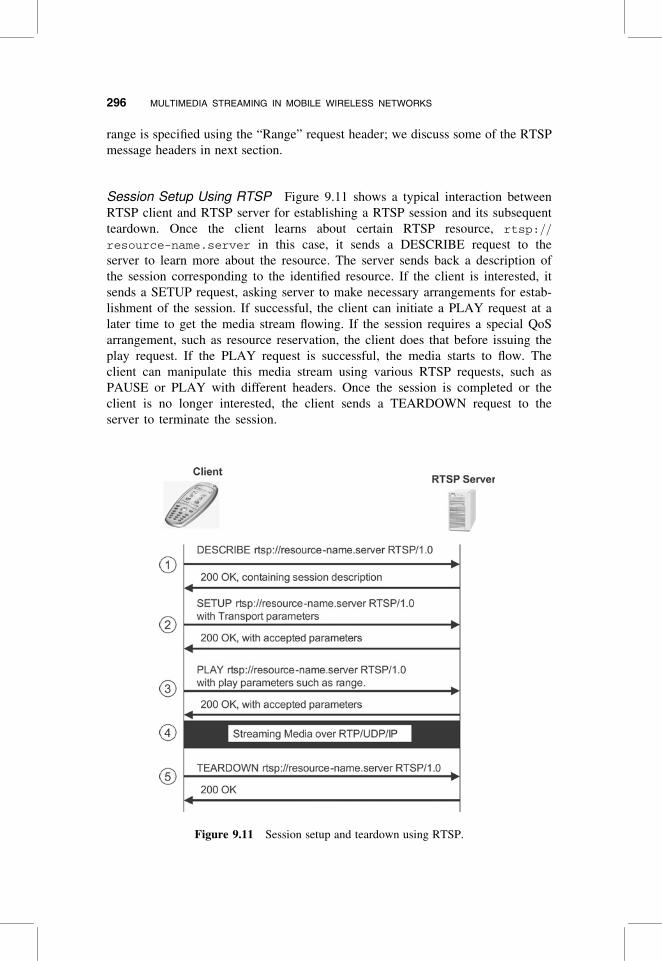
Session Setup Using RTSP Figure 9.11 shows a typical interaction between
RTSP client and RTSP server for establishing a RTSP session and its subsequent
teardown. Once the client learns about certain RTSP resource, rtsp://
resource-name.server in this case, it sends a DESCRIBE request to the
server to learn more about the resource. The server sends back a description of
the session corresponding to the identified resource. If the client is interested, it
sends a SETUP request, asking server to make necessary arrangements for estab-
lishment of the session. If successful, the client can initiate a PLAY request at a
later time to get the media stream flowing. If the session requires a special QoS
arrangement, such as resource reservation, the client does that before issuing the
play request. If the PLAY request is successful, the media starts to flow. The
client can manipulate this media stream using various RTSP requests, such as
PAUSE or PLAY with different headers. Once the session is completed or the
client is no longer interested, the client sends a TEARDOWN request to the
server to terminate the session.
Figure 9.11 Session setup and teardown using RTSP.
296 MULTIMEDIA STREAMING IN MOBILE WIRELESS NETWORKS
9.5.1.2 Session Description ProtocolThe session description protocol (SDP) is widely used for presentation and session
description. This protocol is specified in standards track IETF RFC 2327 [28]. SDP
provides a well-defined format that conveys sufficient information about the multi-
media session to allow the recipients of the session description to participate in the
session. This information is commonly conveyed by SAP protocol that announces a
multimedia session by periodically transmitting an announcement packet at a well-
known multicast address and port number. Alternatively, session descriptions can be
conveyed through electronic email and World Wide Web. The SDP conveys follow-
ing information:
. Session name and purpose
. Media comprising the session
Media type (video, audio, etc.)
Transport Protocol (RTP/UDP/IP)
Media format (MPEG4 video, H.261 video, etc.)
Addresses, port numbers for media
. Time(s) the session is active
The session description using SDP consists of a series of text-based lines (using
the ISO 10646 character set in UTF-8 encoding). Each line is of the form
<type>¼<value>. <type> is strictly one character (derived only from the U.S.
ASCII subset of UTF-8). <value> is generally either a number of fields delimited
by a single space character or a free-format string.
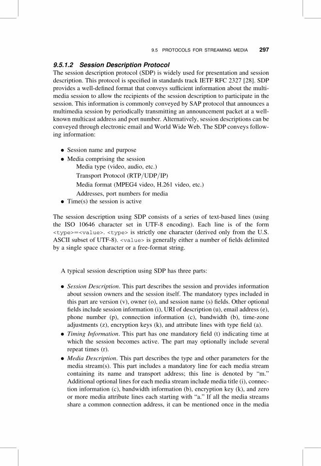
A typical session description using SDP has three parts:
. Session Description. This part describes the session and provides information
about session owners and the session itself. The mandatory types included in
this part are version (v), owner (o), and session name (s) fields. Other optional
fields include session information (i), URI of description (u), email address (e),
phone number (p), connection information (c), bandwidth (b), time-zone
adjustments (z), encryption keys (k), and attribute lines with type field (a).
. Timing Information. This part has one mandatory field (t) indicating time at
which the session becomes active. The part may optionally include several
repeat times (r).
. Media Description. This part describes the type and other parameters for the
media stream(s). This part includes a mandatory line for each media stream
containing its name and transport address; this line is denoted by “m.”
Additional optional lines for each media stream include media title (i), connec-
tion information (c), bandwidth information (b), encryption key (k), and zero
or more media attribute lines each starting with “a.” If all the media streams
share a common connection address, it can be mentioned once in the media
9.5 PROTOCOLS FOR STREAMING MEDIA 297
description part. The value corresponding to most typed fields is not free-form
text and has a certain defined format.
Figure 9.12 illustrates parts of session description with SDP using an example taken
right out of the RFC 2327 [28].
9.5.1.3 Other Session Control ProtocolsThere are a number of other session control protocols available: the most notable
ones are the (1) wireless session protocol [WSP], used with WAP, and (2) the SIP
and H.323 family of protocols, which are typically used for real-time conversational
media communication.
Although these protocols can in principle be used for streaming multimedia with
minor modifications, in practice, these protocols, despite their rich functionalities,
are seldom used for streaming multimedia. In some cases streaming media protocols
may be used in conjunction with conversational media protocols. For example,
RTSP may be used for interacting with a voice or video mail system, while the
remaining infrastructure may be based on SIP. There is, however, some preliminary
discussion to use SIP for streaming media as well. This may eliminate the need for
having multiple protocols of similar functionality at the terminal. This could be
something to look forward to in the future.
9.5.1.4 Description LanguagesA number of description languages are used in today’s multimedia systems to
describe the session integration and scene description, device capabilities,
context, and metadata associated with media. The main purpose of well-formed
description languages is to facilitate consumption of media information by compu-
ters, such as in search engines and semantic Web. However, this is not the only
reason why description languages are used. Synchronized Multimedia Integration
Language (SMIL) [31], for instance, is used to describe the spacetime relationship
Figure 9.12 Parts of session description using SDP.
298 MULTIMEDIA STREAMING IN MOBILE WIRELESS NETWORKS

between a set of multimedia. Other examples of multimedia descriptions include
ISO’s Multimedia Content Description Interface (MPEG-7) and Composite
Capabilities/Preferences Profile (CC/PP) [32]. In the following sections we will
learn about SMIL and CC/PP as they have important role to play in multimedia
content delivery and presentation.
Synchronized Multimedia Integration Language (SMIL) For commercial ser-
vices, media presentation is perhaps just as important as the media itself. Content
providers want to present the media in a manner that is both flexible for commercial
services, such as integrating location specific advertisements with the media presen-
tation, and at same time functional and appealing to the consumer. SMIL, an XML-
based language developed by the World Wide Web Consortium, is the “glue” that
combines various media elements such as video, audio, images, and formatted
text to create an interactive multimedia presentation. SMIL does not control the
session, but it can be used to specify how the media are rendered at the client appli-
cation (user agent). SMIL allows description of the temporal behavior of a multime-
dia presentation, associates hyperlinks with media objects and describes both
temporal and spatial layout of a multimedia presentation on the user device.
SMIL is an HTML-like language and like HTML, it also consists of elements, attri-
butes, and attribute values.
SMIL PRESENTATION EXAMPLE Following is a simple SMIL presentation. It demon-
strates the timing, synchronization, prefetch and layout capabilities of SMIL. The
SMIL user agent completely (100%) prefetches the media objects. It then displays
a video clip and displays a series of static images one after another. The images
appearing in “region2” change every 10 seconds, and those in “region3” change
every second giving impression of a counter. The layout and presentation behavior
is pictorially shown in Figure 9.13 using a video clip showing a moving airplane, and
the images in “region3” change every second.
0 0 0 1 0 2 0 3 0 4 0 5
1 2 3 4 5
0 0 0 1 0 2 0 3 0 4 0 5
0
Region 3
Region 1
Region 2
Root-layout
Time (seconds)
Figure 9.13 A SMIL presentation example.
9.5 PROTOCOLS FOR STREAMING MEDIA 299

1:<smil xmlns¼”http://www.w3.org/2001/SMIL20/Language”>
2:
3:<head>
4: <meta name ¼ ”SMIL Layout Example” content ¼ ”SMIL
Example”/>
5: <layout>
6: <root-layout background-color ¼ ”gray” height ¼ ” 270”
width ¼ ” 210”/>
7: <region id ¼ ”region1” top ¼ ” 5” left ¼ ” 5”
height ¼ ” 200” width ¼ ” 200” />
8: <region id ¼ ”region2” top ¼ ” 222” left ¼ ” 55”
height ¼ ” 48” width ¼ ” 48” />
9: <region id ¼ ”region3” top ¼ ” 222” left ¼ ” 105”
height ¼ ” 48” width ¼ ” 48” />
10: </layout>
11:</head>
12:<body>
13:
14: <seq>
15: <prefetch src ¼ “0.jpg” mediaSize ¼ “100%” />
16: <prefetch src ¼ “1.jpg” mediaSize ¼ “100%” />
17: <prefetch src ¼ “2.jpg” mediaSize ¼ “100%” />
18: <prefetch src ¼ “3.jpg” mediaSize ¼ “100%” />
19: <prefetch src ¼ “4.jpg” mediaSize ¼ “100%” />
20: <prefetch src ¼ “5.jpg” mediaSize ¼ “100%” />
21: <prefetch src ¼ “6.jpg” mediaSize ¼ “100%” />
22: <prefetch src ¼ “7.jpg” mediaSize ¼ “100%” />
23: <prefetch src ¼ “8.jpg” mediaSize ¼ “100%” />
24: <prefetch src ¼ “9.jpg” mediaSize ¼ “100%” />
25: <prefetch src ¼ “video1.mpg” mediaSize ¼ “100%” />
26: </seq>
27:
28: <par endsync ¼ “video1”>
29: <video id ¼ “video1” src ¼ “video1.mpg”
region ¼ “region1” />
30: <seq repeatDur ¼ “indefinite”>
31: <img src ¼ ”0.jpg” region ¼ “region2” dur ¼ “10s”
fill ¼ “freeze”/>
32: <img src ¼ ”1.jpg” region ¼ “region2” dur ¼ “10s”
fill ¼ “freeze”/>
33: <img src ¼ ”2.jpg” region ¼ “region2” dur ¼ “10s”
fill ¼ “freeze”/>
34: <img src ¼ ”3.jpg” region ¼ “region2” dur ¼ “10s”
fill ¼ “freeze”/>
300 MULTIMEDIA STREAMING IN MOBILE WIRELESS NETWORKS

35: <img src ¼ ”4.jpg” region ¼ “region2” dur ¼ “10s”
fill ¼ “freeze”/>
36: <img src ¼ ”5.jpg” region ¼ “region2” dur ¼ “10s”
fill ¼ “freeze”/>
37: </seq>
38: <seq repeatDur ¼ “indefinite”>
39: <img src ¼ ”0.jpg” region ¼ “region3” dur ¼ “1s”
fill ¼ “freeze” />
40: <img src ¼ ”1.jpg” region ¼ “region3” dur ¼ “1s”
fill ¼ “freeze” />
41: <img src ¼ ”2.jpg” region ¼ “region3” dur ¼ “1s”
fill ¼ “freeze” />
42: <img src ¼ ”3.jpg” region ¼ “region3” dur ¼ “1s”
fill ¼ “freeze” />
43: <img src ¼ ”4.jpg” region ¼ “region3” dur ¼ “1s”
fill ¼ “freeze” />
44: <img src ¼ ”5.jpg” region ¼ “region3” dur ¼ “1s”
fill ¼ “freeze” />
45: <img src ¼ ”6.jpg” region ¼ “region3” dur ¼ “1s”
fill ¼ “freeze” />
46: <img src ¼ ”7.jpg” region ¼ “region3” dur ¼ “1s”
fill ¼ “freeze” />
47: <img src ¼ ”8.jpg” region ¼ “region3” dur ¼ “1s”
fill ¼ “freeze” />
48: <img src ¼ ”9.jpg” region ¼ “region3” dur ¼ “1s”
fill ¼ “freeze” />
49: </seq>
50: </par>
51:</body>
52:</smil>
Composite Capabilities/Preferences Profile (CC/PP) RTS does not provide a
very good capability exchange mechanism. In most cases the server decides on the
type of media and its other properties without first consulting the client about its
capabilities. The client may have several capabilities or limitations, which, if com-
municated to the server, would allow the server to customize the presentation and
media based on client capabilities.
The client device may have limited bandwidth, or a constrained display, software
constraints such as support for some SMIL features and not other features, or some
user preferences that may impact the presentation of media at the user agent. CC/PP
can be used to express all these scenarios and more.
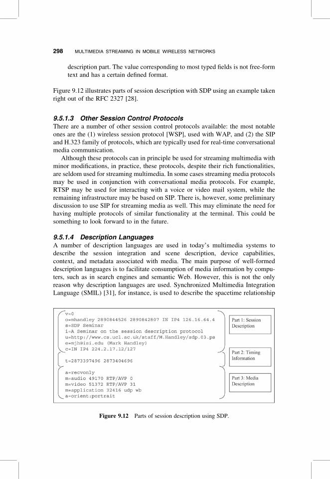
CC/PP OVERVIEW A CC/PP description is a statement of capabilities and profiles
of a device or a user agent. CC/PP is based on resource description framework
9.5 PROTOCOLS FOR STREAMING MEDIA 301
(RDF1) and can be expressed using an XML document or some other structured rep-
resentation format. A CC/PP description is structured such that each profile has a
number of components and each component has one or more related attribute–
value pairs, which are sometimes also referred to as properties. Figure 9.14 shows
CC/PP structure for a hypothetical profile. Two components, HardwarePlatform
and Streaming, and some of their respective attributes are shown. The Hardware-
Profile component above, groups together BitsPerPixel, ColorCapable, and
PixelAspectRatio properties, which are presumably properties related to the
hardware of the device.
As with all the languages and description formats, we must have a set of mutually
understood vocabulary and rules for their interpretation. CC/PP is no exception.
With CC/PP any operational environment may define its own vocabulary and
schema that specify the allowable attributes and values, along with their syntax
and semantics. This vocabulary and schema may be understood only by the relevant
applications. For instance, W3C [32] defines a core vocabulary for print and display,
and WAP forum’s user-agent profile (UAProf) specification WAP [33] defines a
vocabulary that can be used to express different capabilities and preferences
related to the hardware, software, and networking available at the device. A discus-
sion on CC/PP attribute vocabularies can be found in Ref. 34.
CC/PP allows specification of default attributes and values in the schema corre-
sponding to each component. If a user agent’s capabilities and preferences related to
a particular component match the default, it can just specify so without actually
giving details of all the attributes and their values. If values of some of the attributes
differ from the default values, only a device can create a profile containing only the
differing attribute value pairs while referring to the defaults for other attributes. This
mechanism shortens the profile descriptions and saves precious wireless bandwidth.
Other methods of reducing size of profile description include using binary encoding
such as WAP binary XML.
Profile
HardwarePlatform Streaming
More Components
16
BitsPerPixel
yes
1x2
Mono
AudioChannels
8
3GPP-R5
ioPixelAspectRat
ColorCapable MaxPolyphony
PssVersion
Figure 9.14 An example CC/PP profile.
1If you are not familiar with RDF, an excellent premier can be found in [68].
302 MULTIMEDIA STREAMING IN MOBILE WIRELESS NETWORKS
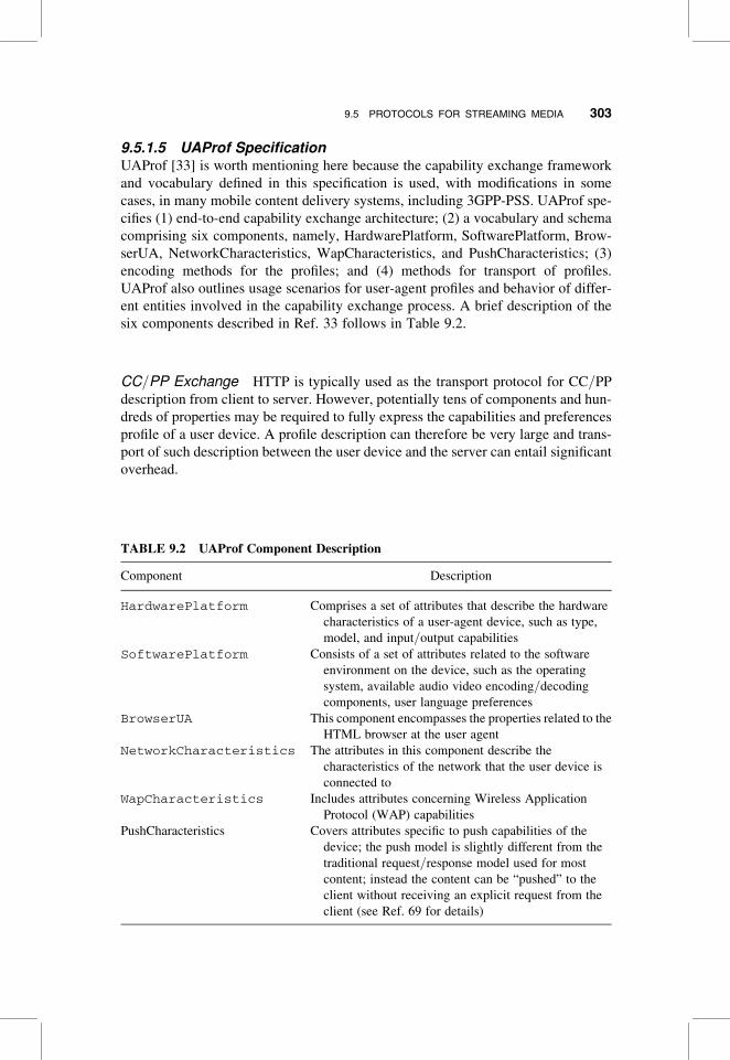
9.5.1.5 UAProf SpecificationUAProf [33] is worth mentioning here because the capability exchange framework
and vocabulary defined in this specification is used, with modifications in some
cases, in many mobile content delivery systems, including 3GPP-PSS. UAProf spe-
cifies (1) end-to-end capability exchange architecture; (2) a vocabulary and schema
comprising six components, namely, HardwarePlatform, SoftwarePlatform, Brow-
serUA, NetworkCharacteristics, WapCharacteristics, and PushCharacteristics; (3)
encoding methods for the profiles; and (4) methods for transport of profiles.
UAProf also outlines usage scenarios for user-agent profiles and behavior of differ-
ent entities involved in the capability exchange process. A brief description of the
six components described in Ref. 33 follows in Table 9.2.
CC/PP Exchange HTTP is typically used as the transport protocol for CC/PP
description from client to server. However, potentially tens of components and hun-
dreds of properties may be required to fully express the capabilities and preferences
profile of a user device. A profile description can therefore be very large and trans-
port of such description between the user device and the server can entail significant
overhead.
TABLE 9.2 UAProf Component Description
Component Description
HardwarePlatform Comprises a set of attributes that describe the hardware
characteristics of a user-agent device, such as type,
model, and input/output capabilities
SoftwarePlatform Consists of a set of attributes related to the software
environment on the device, such as the operating
system, available audio video encoding/decoding
components, user language preferences
BrowserUA This component encompasses the properties related to the
HTML browser at the user agent
NetworkCharacteristics The attributes in this component describe the
characteristics of the network that the user device is
connected to
WapCharacteristics Includes attributes concerning Wireless Application
Protocol (WAP) capabilities
PushCharacteristics Covers attributes specific to push capabilities of the
device; the push model is slightly different from the
traditional request/response model used for most
content; instead the content can be “pushed” to the
client without receiving an explicit request from the
client (see Ref. 69 for details)
9.5 PROTOCOLS FOR STREAMING MEDIA 303
We already saw that CC/PP allows referring to default attribute values, which
may reduce size of the description, but what about the properties that deviate
from default. The CC/PP exchange protocol [35] has been designed with precisely
these constraints in mind. This protocol allows the user agents to specify only the
attributes that differ from default or last capability exchange. This reduces the
size of descriptions significantly. Because of the dependency between different
descriptions sent by a client, the network must maintain state information about pre-
vious a CC/PP exchanges. For this purpose a new logical entity called a CC/PPrepository is introduced. This repository stores the default and predefined profiles.
The CC/PP exchange protocol [35] extends HTTP by defining three new HTTP
headers, two of which are request headers, namely, profile, profile-diff, and
one response header, named profile-warning. The profile header contains a
list of references to (predefined) profiles or profile descriptions expressed carried
in profile-diff header in the same message. profile-diff header contains the
actual profile description. Profile-warning header is used to convey any
warning information to the requestor, such as when the server fails to fully
resolve a profile description. Ref. 33 defines similar headers for use with Wireless
profiled HTTP, and these headers are called x-wap-profile, x-wap-profile-
diff, and x-wap-profile-warning, respectively, and have meanings similar to
those of the corresponding headers defined for CCPP exchange protocol.
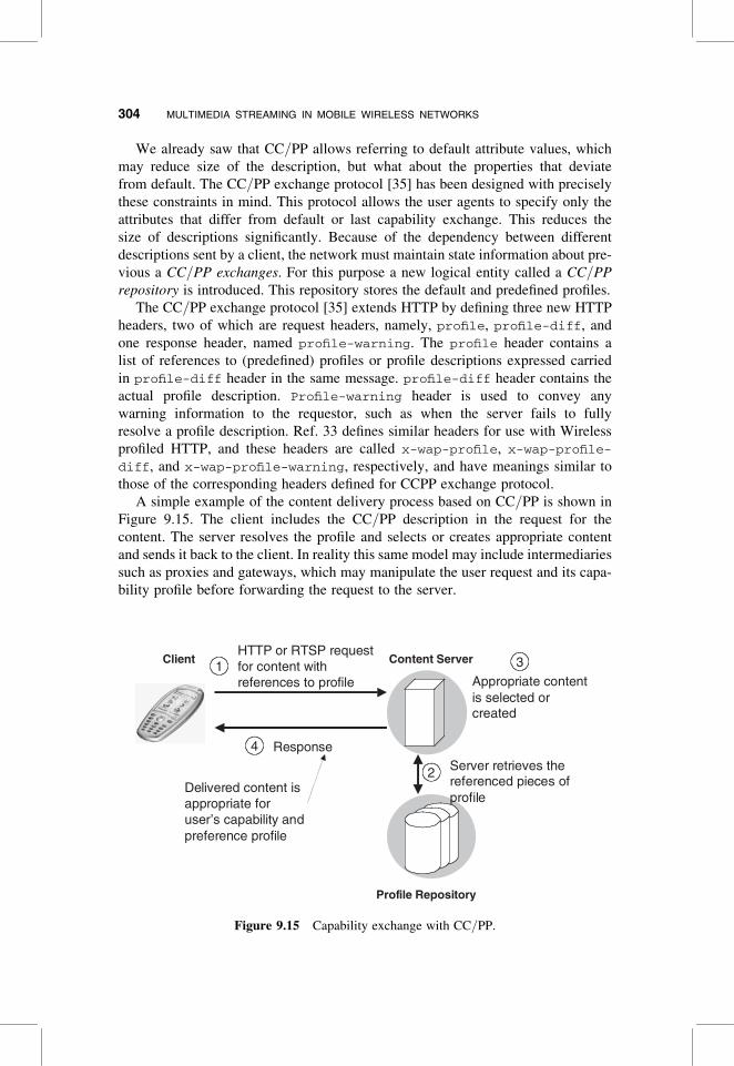
A simple example of the content delivery process based on CC/PP is shown in
Figure 9.15. The client includes the CC/PP description in the request for the
content. The server resolves the profile and selects or creates appropriate content
and sends it back to the client. In reality this same model may include intermediaries
such as proxies and gateways, which may manipulate the user request and its capa-
bility profile before forwarding the request to the server.
Content ServerClientHTTP or RTSP request for content with references to profile
1
4 Response
Profile Repository
Server retrieves the referenced pieces of profile
2
Appropriate content is selected or created
3
Delivered content is appropriate for user’s capability and preference profile
Figure 9.15 Capability exchange with CC/PP.
304 MULTIMEDIA STREAMING IN MOBILE WIRELESS NETWORKS

Needless to say, CC/PP is a generic mechanism for expressing capabilities and
profiles and can be used in a variety of situations besides the classical client–
server scenario depicted in Figure 12.15. It should also be noted here that currently
mostly HTTP is used to carry CC/PP descriptions, RTSP may become more widely
used in the future.
9.5.2 The Streaming Media Transport Protocols
For the application to render the media while they are still being transmitted over the
data network, some care must be taken in media transport. The media transport
mechanisms must provide means through which the media are transported in a
sequential manner, and with all the relevant information about how and when
they must be rendered (e.g., the media format types and the timestamps). Currently
the hypertext transport protocol (HTTP) [36] TCP [37], UDP [38], and real-time
transport protocol (RTP) [39] [coupled with the real-time transport control protocol
(RTCP)] are used for multimedia streaming over the Internet. Among these proto-
cols, only RTP can be regarded as a true real-time transport protocol, but presence
of firewalls that do not understand the streaming protocols and block UDP-based
traffic can sometimes make use of HTTP and TCP unavoidable.
In many scenarios a multimedia session consists of many different streams, each
with its own unique requirements with respect to media transport, thus necessitating
the use of more than one media transport protocols. One such scenario is the 3GPP-
PSS architecture, which we will describe later in this chapter
9.5.2.1 The Real-Time Transport ProtocolThis protocol has emerged as the dominant streaming media transport protocol. The
basic protocol is defined in IETF RFC 1889 [39]. The RFC defines two protocols that
are meant to work in tandem, namely, the RTP for media transport and the accom-
panying protocol called real-time transport control protocol (RTCP) for transport
feedback to the senders from the receivers. While RFC 1889 provides the base spe-
cification, several additional specifications have been developed for packetization
and use with individual media types such as H.263 [40] and GSM-AMR [41]. In
the following text we will briefly overview functionality provided by RTP and
RTCP and their use in streaming media environment.
Figure 9.16 shows the RTP packet format. RTP provides payload type identifi-
cation, fragmentation (M-bit), sequencing, and timing information in each individ-
ual packet. The payload type field allows the application to determine the correct
codec type to use with the media. Fragmentation information allows the appli-
cations to reassemble protocol data units correctly. Timing and sequence infor-
mation allows the applications to recognize any out of sequence packets and
compensate for delay-jitter variations incurred on the network. All of these com-
bined allow an application to render the multimedia stream correctly and
smoothly. RTP also provides synchronization source (SSRC) and contributing
source (CSRC) identifiers to identify the packets belonging to same stream inde-
pendent of the transport layer address. This is especially helpful in multiparty
9.5 PROTOCOLS FOR STREAMING MEDIA 305

streaming scenarios but is rarely used in contemporary streaming multimedia
delivery. RTP is also capable of transporting encrypted media; however, the key
generation and distribution is out of scope of RTP.
RTCP specifies periodic transmission of control packets to all the participants in a
session. It serves four main functions:
1. Feedback on quality of reception of data through RTCP sender and receiver
reports.
2. Carrying a persistent transport level identifier for RTP source. This identifier
is called canonical (CNAME), this is very helpful in multimedia scenarios
where a RTP source may contribute more than one streams. Such as when
transmitting audiovideo streams of a conversation, the common CNAME
for the individual SSRC allows the receiver to recognize these streams as
associated, indicating need for synchronization (e.g., for lip-synchronization).
3. Rate control for RTCP messages. The number of RTCP messages generated
can quickly get out of control in a conference with large number of partici-
pants. This functionality allows the participants to control the rate of RTCP
reports.
4. Session control information for loosely controlled sessions, where, partici-
pants may join and leave without strict membership control. However, stream-
ing multimedia sessions are often tightly controlled and complete session
control information is established via separate session control protocols
such as RTSP and RTCP, allowing only loose control within the parameters
established by the session control protocol.
Figure 9.17 shows the format of RTCP senders report. Receiver reports are similar,
except that the header does not contain the NTP timestamp and there is no sender
information block. The payload type for receiver reports is 201.
Figure 9.16 RTP packet format.
306 MULTIMEDIA STREAMING IN MOBILE WIRELESS NETWORKS

In addition to senders and receivers reports, RTCP also provides for source
description or SDES packets (see Fig. 9.18). These packets include information,
such as name, email, phone number, and geographic location about the synchroni-
zation and contributing sources.
Although RTP is transport-independent as long as the transport protocol provides
multiplexing and correct delivery, because of the stringent delay requirements of
most real-time traffic and high acceptance of IP, UDP is primarily used as transport
Figure 9.17 RTCP sender report packet format.
V=2 P Source Count (SC)
Payload type=SDES=202 Length
0 7 15 23 31
SSRC-1 or CSRC-1
SDES Items for SSRC/CSRC -1
……
SSRC-2 or CSRC-2
SDES Items for SSRC/CSRC -1
……
Figure 9.18 RTCP source description format.
9.5 PROTOCOLS FOR STREAMING MEDIA 307

for RTP. Although RFC 1889 states that RTP uses checksum and multiplexing capa-
bility of UDP, it is worth noting that most media codecs are either not sensitive to bit
errors, or may be encoded with error correction codes; therefore, it is not wise to
discard the entire packet if the checksum fails. In such cases it may be wise to
disable UDP checksum or use protocols such as “UDP-lite” [42,43].
RTP and RTCP are usually used in tandem and multiplexed onto the same
network layer address; for instance, if UDP/IP is used, they will typically share
the IP address. By convention the RTP stream uses an even-numbered port
number and the corresponding RTCP channel uses one immediately following the
odd-numbered port.
As stated earlier, individual profiles for specific media types have been defined.
These profiles specify the payload type, any modifications to the semantics of differ-
ent fields in the header and payload, and any new header types if necessary.
Examples of such media-specific profiles include Ref. 44 for H.263 and Ref. 41
for AMR. These profiles sometimes provide functionality for rate adaptation and
other in-band signaling; for example, Sjoberg et al. [41] allow the receiver to
specify one of several AMR codec rates or modes of operation. Applications
using these media types must conform to the corresponding profiles to ensure
compatibility.
9.5.2.2 Other Media Transport ProtocolsHTTP and RTSP tunneling or plain UDP or TCP are sometimes used for media trans-
port. HTTP and RTSP tunneling is useful in cases where a firewall blocks RTP/UDP
traffic. With HTTP and RTSP tunneling, the streaming media are sent embedded or
interleaved in the body of the HTTP or RTSP messages; this approach, however, can
be highly inefficient in terms of the amount of bandwidth used. But as streaming mul-
timedia gains wider deployment and acceptability, there are more firewalls that
understand the streaming media protocols and can therefore open the desired ports
to allow streaming media. So we will likely see less use of tunneling in the future.
9.6 3GPP PACKET-SWITCHED STREAMING SERVICE
As discussed in previous sections, a basic streaming service consists of streaming
control protocols, transport protocols, media codecs, and scene description proto-
cols. 3GPP has formulated a set of 3G PSS standards to provide mobile packet-
switched streaming service (PSS). The 3GPP standard specifies protocols, codecs
and architecture to provide mobile streaming service. The 3GPP codecs and
media types were discussed in Section 3.3 of this chapter. Figures 9.19 and 9.20
depict the 3GPP protocols and applications used in a PSS client. The protocols
and their applications are
. RTSP and SDP for session setup and description
. SMIL for session layout description
308 MULTIMEDIA STREAMING IN MOBILE WIRELESS NETWORKS
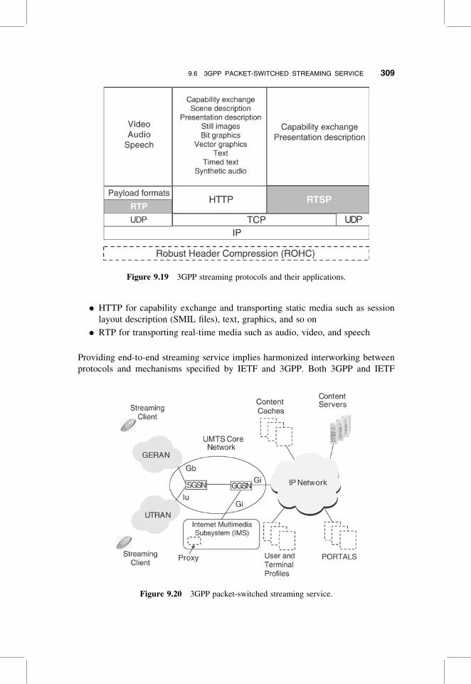
. HTTP for capability exchange and transporting static media such as session
layout description (SMIL files), text, graphics, and so on
. RTP for transporting real-time media such as audio, video, and speech
Providing end-to-end streaming service implies harmonized interworking between
protocols and mechanisms specified by IETF and 3GPP. Both 3GPP and IETF
Figure 9.19 3GPP streaming protocols and their applications.
Figure 9.20 3GPP packet-switched streaming service.
9.6 3GPP PACKET-SWITCHED STREAMING SERVICE 309
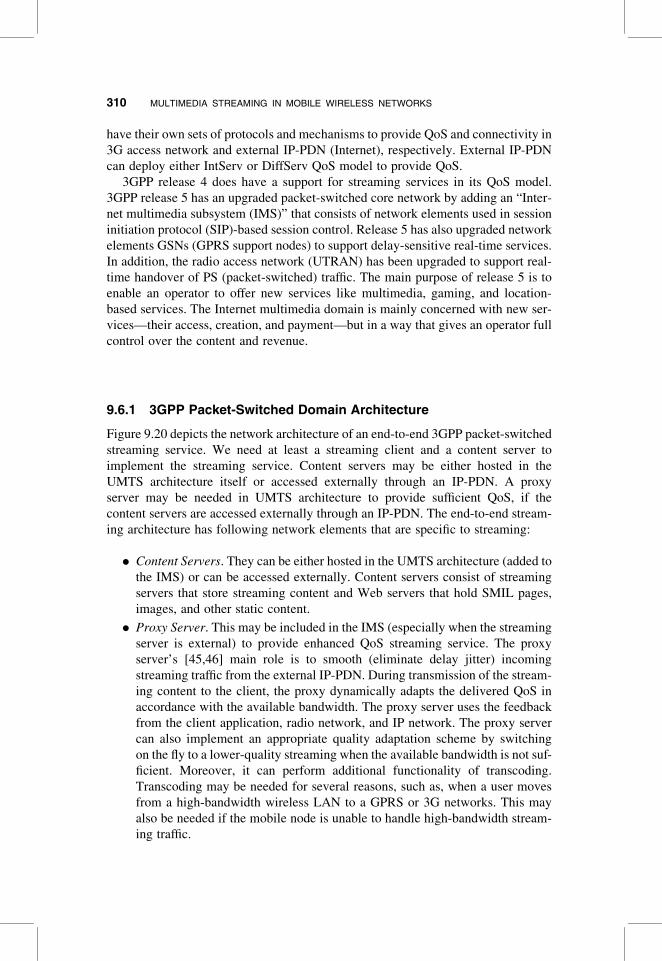
have their own sets of protocols and mechanisms to provide QoS and connectivity in
3G access network and external IP-PDN (Internet), respectively. External IP-PDN
can deploy either IntServ or DiffServ QoS model to provide QoS.
3GPP release 4 does have a support for streaming services in its QoS model.
3GPP release 5 has an upgraded packet-switched core network by adding an “Inter-
net multimedia subsystem (IMS)” that consists of network elements used in session
initiation protocol (SIP)-based session control. Release 5 has also upgraded network
elements GSNs (GPRS support nodes) to support delay-sensitive real-time services.
In addition, the radio access network (UTRAN) has been upgraded to support real-
time handover of PS (packet-switched) traffic. The main purpose of release 5 is to
enable an operator to offer new services like multimedia, gaming, and location-
based services. The Internet multimedia domain is mainly concerned with new ser-
vices—their access, creation, and payment—but in a way that gives an operator full
control over the content and revenue.
9.6.1 3GPP Packet-Switched Domain Architecture
Figure 9.20 depicts the network architecture of an end-to-end 3GPP packet-switched
streaming service. We need at least a streaming client and a content server to
implement the streaming service. Content servers may be either hosted in the
UMTS architecture itself or accessed externally through an IP-PDN. A proxy
server may be needed in UMTS architecture to provide sufficient QoS, if the
content servers are accessed externally through an IP-PDN. The end-to-end stream-
ing architecture has following network elements that are specific to streaming:
. Content Servers. They can be either hosted in the UMTS architecture (added to
the IMS) or can be accessed externally. Content servers consist of streaming
servers that store streaming content and Web servers that hold SMIL pages,
images, and other static content.
. Proxy Server. This may be included in the IMS (especially when the streaming
server is external) to provide enhanced QoS streaming service. The proxy
server’s [45,46] main role is to smooth (eliminate delay jitter) incoming
streaming traffic from the external IP-PDN. During transmission of the stream-
ing content to the client, the proxy dynamically adapts the delivered QoS in
accordance with the available bandwidth. The proxy server uses the feedback
from the client application, radio network, and IP network. The proxy server
can also implement an appropriate quality adaptation scheme by switching
on the fly to a lower-quality streaming when the available bandwidth is not suf-
ficient. Moreover, it can perform additional functionality of transcoding.
Transcoding may be needed for several reasons, such as, when a user moves
from a high-bandwidth wireless LAN to a GPRS or 3G networks. This may
also be needed if the mobile node is unable to handle high-bandwidth stream-
ing traffic.
310 MULTIMEDIA STREAMING IN MOBILE WIRELESS NETWORKS

. User and Profile Servers. These servers store user preferences and device capa-
bilities. This information can be used to control presentation of streamed media
to a mobile user.
. Content Cache. Content cache can be optionally used to improve the overall
service quality.
. Portals. Portals are servers that allow convenient access to streamed media
content. For example, a portal might offer content browse and search facilities.
In the simplest case, it can be a Webpage with a list of links to streaming content.
Apart from the abovementioned network elements that are specific to streaming
service, other network elements in the 3GPP UMTS architecture play a significant
role in the QoS management of streaming service. The UMTS radio access
network (UTRAN) ensures seamless handover between basestations with minimal
disruption to ongoing real-time services. The radio resource control (RRC) protocol
[1] (3GPP-TS-25.331) is used for controlling resources on the UTRAN (universal ter-
restrial radio access network). The radio access network application part (RANAP)
protocol [1] (TS-25.431) is used between UTRAN and core network entities. The
serving GPRS support node (SGSN) acts as the gateway for the entire packet-based
communications between user equipments (UEs) within its serving area. The
SGSN is responsible for packet routing and transfer, mobility management (attach/detach and location management), logical link management, authentication, and char-
ging functions. The gateway GPRS support node (GGSN) acts as a gateway between
UMTS core network and external IP-PDN. There is an active PDP context for every
active packet-switched bearer or session. The PDP context is stored in UE, SGSN, and
GGSN. With an active PDP context, the UE is visible for the external IP-PDN and is
able to send and receive data packets. The PDP context describes the characteristics of
the session. It contains a PDP type (e.g., IPv4), the IP address assigned to the UE,
requested QoS, and the address of the GGSN that serves as the access point
to the IP-PDN. Table 9.3 shows the different QoS classes supported in the UMTS
architecture [1].
The PDP activitation (see Fig. 9.21) in the UMTS architecture works as follows.
The UE first sends an “Activate PDP context request” message to the SGSN through
the session management (SM) protocol. SGSN contacts the home location register
TABLE 9.3 UMTS QoS Classes
Class Requirements Example
Conversational Very delay-sensitive Traditional voice; VoIP
Streaming Better channel coding;
Retransmission
One-way real-time
audio/video
Interactive Delay-insensitive Telnet; interactive e-mail;
WWW
Background Delay-insensitive Ftp; background email
9.6 3GPP PACKET-SWITCHED STREAMING SERVICE 311

(HLR) and performs authentication and authorization functions. SGSN then per-
forms the local admission and initiates radio access bearer (RAB) assignment pro-
cedure in the RAN/GERAN through RANAP procedure. A local call admission
based on the availability of radio resources and UMTS QoS attributes is mapped
on radio bearer (RB) parameters used in the physical and link layers. After the estab-
lishment of RB, SGSN sends a “Create PDP context request” message to the GGSN.
The GGSN performs local admission control and creates a new entry in the PDP
context table that enables the GGSN to route data between SGSN and external
IP-PDN. Afterward, the GGSN returns a confirmation message “Create PDP
context response” to the SGSN” that contains the PDP address. The SGSN
updates its local PDP context table and sends an “Activate PDP context accept”
message to the UE.
9.6.2 The 3GPP PSS Framework
The 3GPP PSS specifications consist of three 3GPP technical specifications: 3GPP
TS 22.233, 3GPP TS 26.233, and 3GPP TS 26.234. PSS provides a framework for
IP-based streaming applications in 3G networks. This framework is very much in
line with what we have discussed so far in this chapter. This framework uses CC/PP for capability exchange (see Fig. 9.22), SMIL for presentation description, and
UE UTRAN/GERAN SGSN GGSN
Radio Bearer
Activate PDP Context RequestSecurity Functions
RAB Assignment Request
RAB Assignment Response
Create PDP Context Request
Create PDP Context Response
Activate PDP Context Accept
Figure 9.21 PDP context activation procedure.
312 MULTIMEDIA STREAMING IN MOBILE WIRELESS NETWORKS

RTSP for session control SDP for session description. However, there are minor
differences here and there. Let’s go over these one by one.
9.6.2.1 Streaming Media Session Setup Procedures for PSSFigure 9.23 shows an example of a simple session establishment. The first step is to
know what content to get and where to start. The client can obtain the URI of the
content from an SMIL presentation document, a simple Webpage, or an email, or
just simply by word of mouth. Once the URI is known, the client application
sends a request for the primary PDP context that is opened to allocate the IP
address for the UE as well as the access point. The primary PDP context is used
to access content servers in either IMS domain or external IP-PDN. Since the
primary PDP context is used for RTSP signaling, it is created with UMTS interactive
QoS profile. A socket is opened for RTSP signaling and is tied to the primary PDP
context. The client can now query the content server to learn more about the content
using RTSP DESCRIBE request.2 The client may include its CC/PP description in
the request. The client does not need to include the profile description if it is sure that
the URI that it is using in the RTSP request already points to a resource that is com-
patible with its profile. Such would be the case if the URI were obtained from an
SMIL document, which was obtained after presenting a valid CC/PP description.
If the profile is included, it is carried using the x-wap-profile and the x-wap-
profile-diff headers for CC/PP exchange protocol that we discussed earlier.
Device capability
prof ilesMatching
Content Server
StreamingClient
Device Profile Server
HTTP/RTSP requestincluding URL descand profileDiffheaders
HTTP Requestfor a device
capabilityprofile
HTTP Responsewith device
capability profile
Figure 9.22 Capability negotiation mechanism applied in PSS.
2RTSP DESCRIBE is mandatory in 3GPP-PSS architecture; however, IETF does not mandate its use.
9.6 3GPP PACKET-SWITCHED STREAMING SERVICE 313

If the profile description is included, the server can find or create content that is
most suitable for the client’s request URI and its profile. Otherwise it just
selects the default content corresponding to the URI. The server sends back the
response with the description of the session that will be used to deliver the selected
content.
On receiving the description, the client can determine whether it likes the descrip-
tion, which it is likely to be the case because it has presumably been tailored to the
client’s capabilities and preferences. The client can now send a SETUP request to
the server, asking it to make necessary arrangements for the streaming session.
The server acknowledges the SETUP request by sending a “200 OK” response
message back to the client. The client now needs to establish a PDP context that
is suitable for the anticipated multimedia streaming session. It does so by opening
two sockets for RTP and RTCP traffic and tying it to two secondary PDP contexts.
The secondary PDP contexts are assigned appropriate UMTS QoS profiles. The sec-
ondary PDP contexts reuse the same IP address and access point as the primary PDP
context.
Now that everything is ready, the client can send a PLAY request asking the
content server to start the streaming session. The streaming media are typically
transported over UDP/RTP/IP protocols as described in SDP.
Figure 9.23 shows the presentation and content server as single entity, but these
may in fact be logically and physically separate entities.
UE GGSN Presentation and content server
[RTSP]DESCRIBE [with capability and preference profile]
[RTSP]200 OK [session description suitable for the device profile][RTSP]SET UP
[RTSP]200 OK
[RTSP]PLAY
[RTSP]200 OK
RTP and RTCP flows
Secondary PDP context activation(one for RTP traffic and another
For RTCP)[see Figure 9.21]
Primary PDP context activation(RTSP) signaling[see Figure 9.21]
Figure 9.23 Streaming multimedia session establishment in PSS.
314 MULTIMEDIA STREAMING IN MOBILE WIRELESS NETWORKS

9.7 MULTIMEDIA SERVICES IN MOBLE AND WIRELESSENVIRONMENTS
The main factors that differentiate wireless mobile environments are
. Limited Bandwidth and Error-Prone Channel. The channel characteristics of a
wireless channel have a very unpredictable time-varying behavior due to
several factors such as interference, multipath fading, and atmospheric con-
ditions. The last hop of communication is wireless, which not only offers rela-
tively low bandwidth, but also suffers from higher bit error rate (BER).
Furthermore, retransmissions needed to recover from these errors induce vari-
able delay across the wireless channels.
. The Movement. The mobile users move!! The movement triggers a handoff
mechanism to minimize interruption to an ongoing session. The wireless
channel characteristics may vary significantly from one segment of the
network to another. Since the handoffs almost always incur packet loss, they
further aggravate the already lossy nature of wireless medium. Finally, the
relative pathlength from the server to the clients may vary as the clients
move across networks. This is especially true if the server is close to the
edge, as in the content distribution networks.
In the following text we will cover some recent proposals to alleviate the problems
that arise as a result of these mobility and error-prone problems faced by mobile
content delivery systems. Also, we look into the research issues regarding providing
streaming service in heterogeneous network environments.
9.7.1 Differentiating Transmission Error Lossesfrom Congestion Losses
In the wired and wide area Internet, most of the packet loss occurs as a result of con-
gestion. In wireless environments, however, the major source of packet loss is trans-
mission errors over the wireless channel. The natural approach for avoiding packet
losses due to congestion is rate control and slowing down the sender. But this
approach is not suitable for avoiding or recovering from errors on wireless channels.
The techniques used for error recovery or packet loss avoidance over the wireless
channels build better error resiliency in the packets so that even if some packets
are dropped, they can still be recovered at the receiver. Alternatively, some
senders use aggressive retransmissions, but that is bound to introduce congestion
problem.
A typical mobile multimedia delivery environment comprises both wired and
wireless links. In such an environment an end-to-end feedback mechanism, such
as RTCP feedback messages can convey information only about the net end-to-
end packet loss and there is no way for the sender to ascertain whether the packet
was lost on the wired network or the wireless network. Since counteracting the
9.7 MULTIMEDIA SERVICES IN MOBLE AND WIRELESS ENVIRONMENTS 315
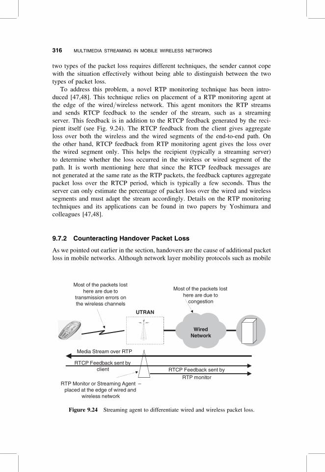
two types of the packet loss requires different techniques, the sender cannot cope
with the situation effectively without being able to distinguish between the two
types of packet loss.
To address this problem, a novel RTP monitoring technique has been intro-
duced [47,48]. This technique relies on placement of a RTP monitoring agent at
the edge of the wired/wireless network. This agent monitors the RTP streams
and sends RTCP feedback to the sender of the stream, such as a streaming
server. This feedback is in addition to the RTCP feedback generated by the reci-
pient itself (see Fig. 9.24). The RTCP feedback from the client gives aggregate
loss over both the wireless and the wired segments of the end-to-end path. On
the other hand, RTCP feedback from RTP monitoring agent gives the loss over
the wired segment only. This helps the recipient (typically a streaming server)
to determine whether the loss occurred in the wireless or wired segment of the
path. It is worth mentioning here that since the RTCP feedback messages are
not generated at the same rate as the RTP packets, the feedback captures aggregate
packet loss over the RTCP period, which is typically a few seconds. Thus the
server can only estimate the percentage of packet loss over the wired and wireless
segments and must adapt the stream accordingly. Details on the RTP monitoring
techniques and its applications can be found in two papers by Yoshimura and
colleagues [47,48].
9.7.2 Counteracting Handover Packet Loss
As we pointed out earlier in the section, handovers are the cause of additional packet
loss in mobile networks. Although network layer mobility protocols such as mobile
Wired Network
UTRAN
Most of the packets lost here are due to
transmission errors on the wireless channels
Most of the packets lost here are due to
congestion
Media Stream over RTP
RTCP Feedback sent by client RTCP Feedback sent by
RTP monitorRTP Monitor or Streaming Agent –
placed at the edge of wired and wireless network
Figure 9.24 Streaming agent to differentiate wired and wireless packet loss.
316 MULTIMEDIA STREAMING IN MOBILE WIRELESS NETWORKS

IP [49] and fast mobile IP [50] attempt to provide seamless handovers during host
movement, some packet loss is inevitable because of signaling propagation delay.
A novel end-to-end technique for soft IP handover has been proposed [51].
Figure 9.25 shows an overview of this scheme.
This scheme assumes that the receiver host is at least temporarily attached to mul-
tiple interfaces during the handoff process. The receiver host signals this situation to
the sender, along with the information about the interfaces, such as their IP addresses
and their relative priority based on signal strength, estimated bandwidth, or packet
loss rate on individual interfaces.
The IP stack on the sender host then generates redundant error correction
symbols, denoted as F1, F2, D1, and so on in Figure 9.25, and dispatches them to
the multiple interfaces of the receiver. Reed–Solomon codes are used to generate
the redundant symbols [51]. In general, if a message is extended from k symbols
to n symbols through addition of (n2 k) redundant symbols, then up to (n2 k)
redundant symbols can be recovered at the receiver node. For example, in
Figure 9.25 n ¼ 2k, that is, there are just as many redundant symbols as the
symbols in the original message; thus the receiver should be able to recover the
application data even when any n symbols are lost.
Application Data
D1 D1 D1
D1 D2 D3 F1 F2 F3
D1 D2 D3 F1 F2 F3
D1 D2D3 F1F2 F3
D1 D2D3 F1F2 F3
Network
(a)
(b)
(c)
Network Layer multiplexes the data between destination interfaces based on the priority assigned by the application and dispatches them accordingly
Application data can be recovered if some packets are lost on either interfaces
Transport Layer (a) fragments the application data, (b) generates error correction codes and (c) attaches the transport header
Multihomed bicastcapable host in handover
situation
Figure 9.25 Bicasting forward error correction codes.
9.7 MULTIMEDIA SERVICES IN MOBLE AND WIRELESS ENVIRONMENTS 317
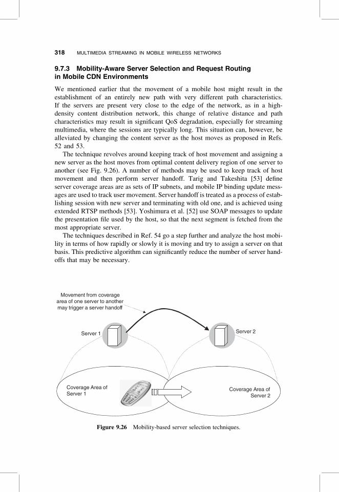
9.7.3 Mobility-Aware Server Selection and Request Routingin Mobile CDN Environments
We mentioned earlier that the movement of a mobile host might result in the
establishment of an entirely new path with very different path characteristics.
If the servers are present very close to the edge of the network, as in a high-
density content distribution network, this change of relative distance and path
characteristics may result in significant QoS degradation, especially for streaming
multimedia, where the sessions are typically long. This situation can, however, be
alleviated by changing the content server as the host moves as proposed in Refs.
52 and 53.
The technique revolves around keeping track of host movement and assigning a
new server as the host moves from optimal content delivery region of one server to
another (see Fig. 9.26). A number of methods may be used to keep track of host
movement and then perform server handoff. Tarig and Takeshita [53] define
server coverage areas are as sets of IP subnets, and mobile IP binding update mess-
ages are used to track user movement. Server handoff is treated as a process of estab-
lishing session with new server and terminating with old one, and is achieved using
extended RTSP methods [53]. Yoshimura et al. [52] use SOAP messages to update
the presentation file used by the host, so that the next segment is fetched from the
most appropriate server.
The techniques described in Ref. 54 go a step further and analyze the host mobi-
lity in terms of how rapidly or slowly it is moving and try to assign a server on that
basis. This predictive algorithm can significantly reduce the number of server hand-
offs that may be necessary.
Server 1
Coverage Area of Server 1
Movement from coverage area of one server to another may trigger a server handoff
Server 2
Coverage Area of Server 2
Figure 9.26 Mobility-based server selection techniques.
318 MULTIMEDIA STREAMING IN MOBILE WIRELESS NETWORKS

9.7.4 Architectural Considerations to Provide Streaming Servicesin Integrated Cellular/WLAN Environments
The wireless LAN is fast emerging as a complementary technology to 3G networks.
This technology provides very high-speed access (11 Mbps for 802.11b and
54 Mbps for 802.11a) but covers very small area and allows limited mobility. On
the other hand, the 3G technology provides access at relatively low speed
(�100 kbps for GPRS) to medium speed (�2 Mbps for UMTS) but covers a wide
area and allows high mobility. A number of interworking mechanisms [55–57]
have been developed to integrate these two technologies into a single wireless
data network that allows very high-speed access at hotspot areas such as airports
and shopping malls. Integration of the WLAN and the cellular network falls in
two categories depending on who owns and manages the WLAN. For example,
operators can own and manage WLANs to augment their cellular data networks.
Thus, an operator can gain competitive advantage by providing enhanced data ser-
vices at strategic locations such as airports and hotels. In the alternative scenario an
independent wireless Internet service provider (WISP) or enterprise can own the
WLAN. In either of the two cases an end user can obtain very high quality streaming
service in hotspot locations.
Two methods are used to integrate cellular and WLAN networks: tight coupling
and loose coupling as illustrated in Figure 9.27. The architectural issues to provide
seamless streaming service for both the methods are described in the following
paragraphs.
SGSN GGSN Gi
AP AP
APIWU
AP AP
APIWU
Loose Coupling
Tight Coupling
Gi
WLAN
WLAN
IP Network
Internet MultimediaSubsystem (IMS)
Proxy
ContentServers
StreamingClient
GERAN/UTRAN
Gb/Iu
UMTS CoreNetwork
Figure 9.27 Generalized integrated UMTS/WLAN architecture.
9.7 MULTIMEDIA SERVICES IN MOBLE AND WIRELESS ENVIRONMENTS 319
9.7.4.1 Tight CouplingUnder this integration scheme, the WLAN is connected to the GPRS core network
in the same manner as any other radio access network (RAN), such as GPRS RAN
(GERAN) and UMTS terrestrial network (UTRAN). The WLAN is deemed as a
new radio access technology within the cellular systems. The WLAN may either
emulate a radio network controller (RNC) or a SGSN. From the core network
point of view, the WLAN is like any other GPRS routing area (RA) in the
system. An interworking unit (IWU) is needed to interface the WLAN to the
GPRS core network. The main advantage of this solution is that the mechanisms
for mobility, QoS, and security in the core network can be reused. Within this
architecture the handover takes place when a mobile user either enters or leaves
a hotspot area. The IP address allocated to the mobile user under this scheme
does not change during the handover process since the mobile user still remains
under the same GGSN. The hotspot areas and cellular coverage areas normally
overlap, and the handover is based on end user’s desire. For example, a mobile
user, receiving multimedia streaming service, would like to hand over to the
WLAN when moving into the hotspot area to improve performance. Since the bot-
tleneck bandwidth in wireless environments lies in the air interface, the transcod-
ing functionality (in the proxy server) may not be needed in the delivery path when
the mobile user hands over from the cellular RAN to the WLAN. This scheme may
also require implementation of additional QoS adaptation mechanisms to support
seamless handover between the WLAN and the cellular RAN for real-time
applications such as streaming.
9.7.4.2 Loose CouplingUnder this integration scheme, the WLAN interfaces directly with the IP-PDN (e.g.,
the Internet) and has no direct interface with the GPRS core network. In this scen-
ario, WLANs and cellular networks are two separate access networks. Loose coup-
ling scheme may deploy IETF-based protocols to handle authentication, accounting,
and mobility. The WLAN appears as a visiting network to the UMTS core network.
A mobile user is typically allocated a new IP address while handing over from the
UMTS network to the WLAN or vice versa. Seamless handover under this scheme
may require advanced mechanisms like context transfer [50] (session context, QoS
context, security context, etc.) and resource reservation. Providing seamless stream-
ing service under this integration scheme is an open research problem.
The streaming in mobile and wireless environments is a subject of active
research. Some of the open research issues to provide multimedia streaming services
in mobile and wireless environments are
. Seamless service during interdomain and intertechnology handoffs
. Dynamic QoS adaptations and channel allocations
. Optimizations across lower and higher layers
. Efficient micromobility protocols [58] to make smoother intradomain
handovers
320 MULTIMEDIA STREAMING IN MOBILE WIRELESS NETWORKS

. Secured streaming, digital rights management schemes
. Efficient implementations of multicast streaming services
Some of the more recent studies on these topics are listed at the end of this chapter
[e.g., 3, 4, 59–67].
9.8 CONCLUSIONS
This chapter addresses the architectural and design issues to provide streaming ser-
vices in wireless environments. Supporting streaming services in wireless environ-
ments is a big challenge, due to error-prone wireless channels and mobility-
induced factors. Also, limited buffering and processing power available in portable
mobile devices impact the design of wireless access network architecture. A lot of
research work has been done to address these issues [51,54,59–62]. The wireless
access network architecture should implement appropriate mechanisms to mitigate
the impact of wireless/mobility-induced factors in order to minimize the resource
and processing requirements at the mobile terminal. We have discussed some of
these research issues and related work. The chapter gives a general overview of an
end-to-end architecture including network elements and protocols to provide stream-
ing services in wireless/mobile environments. We also describe packet-switched
streaming service architecture developed by 3GPP (abbreviated 3GPP-PSS).
There has been widespread effort to develop adaptive modulation, equalization
and coding schemes that uses the real-time estimation of channel characteristics
to achieve certain performance objectives such as error rate and delay at the physical
layer. A number of smart-antenna-based technologies have been developed that use
space diversity techniques to mitigate the impact of multipath fading and achieve
higher capacity. Also, there has been lot of work on micromobility protocols [58]
(such as FMIP) at the network layer to reduce mobility-induced disruption. There
is a need to look into joint optimization issues across various layers to provide
good-quality seamless streaming service in wireless/mobile environments. The
wireless bandwidth can be utilized in an effective manner if the lower layers have
detailed understanding of the application requirements. A well-defined interface
between IP layer and lower layers would be very useful in next-generation wireless
networks. Indeed, the EU IST project BRAIN has already defined an IP-to-Wireless
(IP2W) interface for this purpose. There are still a number of design issues regarding
providing streaming services in heterogeneous wireless networks that include
various wireless access technologies (3G, WLAN, Bluetooth, etc). Secured stream-
ing is yet another area of active research. The ability to protect the intellectual prop-
erty rights of the content owners will be a key factor in the mobile digital content
market.
Multimedia streaming services are becoming very popular on the Internet, and
when these services become mobile, animation, music, and news services will be
available to users regardless of the location and time. Next-generation mobile
9.8 CONCLUSIONS 321

networks will combine the standardized streaming service with a range of unique
services to offer a wide range of innovative and exciting multimedia services to
the rapidly growing mobile market.
REFERENCES
1. The Third Generation Partnership Project, http://www.3gpp.org.
2. The Third Generation Partnership Project 2, http://www.3gpp2.org/.
3. I. Elson et al., Streaming technology in 3G mobile communication systems, IEEE
Comput., 34(9): 46–52. (Sept. 2001).
4. H. Montes et al., Deployment of IP multimedia streaming services in third-generation
mobile networks, IEEE Wireless Commun. 84–92 (Oct. 2002).
5. D. Wu et al., Streaming video over the Internet: Approaches and directions, IEEE Trans.
Circuits Syst. Video Technol. 11(3) (March 2001).
6. S. Keshav, An Engineering Approach to Computer Networking: ATM Networks, the
Internet, and the Telephone Network, Addison-Wesley Professional.
7. S. Floyd and K. Fall, Promoting the use of end-to-end congestion control in the Internet,
IEEE Trans. Network., 7: 458–472, (Aug. 1999).
8. S. Floyd et al., Equation based congestion control for unicast applications, Proc. ACM
SIGCOMM, Stockholm, Sweden, Aug. 2000, pp. 43–56.
9. The TCP-Friendly Web Page, URL: http://www.psc.edu/networking/
tcp_friendly.html.
10. R. Rejaie, M. Handley, and D. Estrin, RAP: An end-to-end rate-based congestion control
mechanism for real-time streams in the Internet, Proc. IEEE INFOCOM ’99, March
1999, Vol. 3, pp. 1337–1345.
11. S. McCanne, V. Jacobson, and M. Vetterli, “Receiver Driven Layered Multicast,” Proc.
of ACM Sigcomm, pp. 117–130, Palo Alto, CA, USA, Aug. 1996.
12. R. Rejaie, M. Handley, and D. Estrin, Quality adaptation for congestion controlled play-
back video over the Internet, Proc. ACM SIGCOMM’99, Cambridge, Sept. 1999, pp.
1337–1345.
13. Q. Guo et al., Sender-adaptive and receiver-driven video multicasting, Proc. IEEE Int.
Symp. Circuits and Systems (ISCAS 2001), Sydney, Australia, May 2001.
14. Y. Wang, M. T. Orchard, and A. R. Reibman, Multiple description image coding for
noisy channels by pairing transform coefficients, Proc. IEEE Workshop on Multimedia
Signal Processing, June 1997, pp. 419–424.
15. Xue Li et al., Layered video multicast with retransmission (LVMR): Evaluation of error-
recovery schemes, Proc. INFOCOM’98, March 29–April 1998, Vol. 3, pp. 1062–1072.
16. S. Shenker, C. Patridge, and R. Guerin, Specification of the Guaranteed Quality of
Service, RFC 2212.
17. S. Blake et al., An Architecture for Differentiated Services, RFC 2475.
18. R. Braden et al., Resource Reservation Protocol (RSVP)—Version 1 Functional Specifi-
cation, RFC 2205.
19. D. Durham et al., The COPS (Common Open Policy Service) Protocol, RFC 2748.
20. T. Sikora, MPEG digital video-coding standards, IEEESignal Process.Mag., (Sept. 1997).
322 MULTIMEDIA STREAMING IN MOBILE WIRELESS NETWORKS

21. T. Sikora, The MPEG-4 video standard verification model, IEEE Trans. Circuits Syst.
Video Technol., 7(1) (Feb. 1997).
22. R. Talluri, Error-resilient video coding in the ISO MPEG-4 standard, IEEE Commun.
Mag., (June 1998).
23. N. Poll, MPEG digital audio coding, IEEE Signal Process. Mag., (Sept. 1997).
24. 3GPP, Transparent End-to-End Packet-Switched Streaming Service (PSS): Protocols and
Codes (Release 5), Generation Partnership Project TS 26.234. V5.4.0.
25. H. Schulzrinne, A. Rao, and R. Lanphier, Real Time Streaming Protocol (RTSP). IETF
Standards Track RFC 2326, April 1998.
26. A. Barbir, B. Cain, R. Nair, and O. Spatscheck, Known CN Request-Routing Mechan-
isms, IETF Work in Progress, April 2003. (Note: CDI working group at IETF has
concluded.)
27. M. Handley, C. Perkins, and E. Whelan, Session Announcement Protocol, IETF Exper-
imental RFC 2974, Oct. 2000.
28. M. Handley, and V. Jacobson, SDP: Session Description Protocol, IETF Standards Track
RFC 2327, April 1998.
29. J. Rosenberg et al., SIP: Session Initiation Protocol, IETF Standards track RFC 3261 June
2002.
30. H.323v5, ITU-T Recommendation H.323, Packet-Based Multimedia Communications
Systems, 2003.
31. http://www.w3.org/TR/2001/REC-smil20-20010807/.
32. Composite Capabilities/Preference Profiles (CC/PP), Structure and Vocabularies,
http://www.w3c.org/TR/CCPP-struct-vocab/.
33. WAP User Agent Profile Specification, Oct. 2001.
34. CC/PP Attribute Vocabularies, http://www.w3.org/TR/2000/WD-CCPP-vocab-
20000721/.
35. Capability Exchange Using HTTP Extension Framework, http://www.w3.org/TR/
NOTE-CCPPexchange.
36. R. Fielding, et al., Hypertext Transfer Protocol—HTTP/1.1, IETF Standards Track RFC
2616, June 1999.
37. Transmission Control Protocol, IETF RFC 793, Sept. 1981.
38. J. Postel, User Datagram Protocol, RFC 768.
39. H. Schulzrinne, S. Casner, R. Frederick, and V. Jacobson, RTP: A Transport Protocol for
Real-Time Applications, IETF Standards Track RFC 1889, Jan. 1996.
40. C. Bormann et al., RTP Payload Format for the 1998 Version of ITU-T Recommendation.
H.263 Video (H.263þ ), IETF Standards Track RFC 2429, Oct. 1998.
41. J. Sjoberg et al., Real-Time Transport Protocol (RTP) Payload Format for the Adaptive
Multi-Rate (AMR) and Adaptive Multi-Rate Wideband (AMR-WB) Audio Codecs, RFC
3267.
42. L.-A. Larzon, M. Degermark, and S. Pink, The UDP-Lite Protocol, IETF Internet Draft,
Work in Progress, Dec. 2002.
43. L.-A. Larzon, M. Degermark, and S. Pink, UDP Lite for Real Time Multimedia Appli-
cations, HPL-IRI-1999-001, April 1999.
44. J. Sjoberg et al., Real-Time Transport Protocol (RTP) Payload Format and File Storage
Format for the Adaptive Multi-Rate (AMR) and Adaptive Multi-Rate Wideband (AMR-
WB) Audio Codecs, IETF Standards Track RFC 2429, June 2002.
REFERENCES 323
45. S. Sen, J. Rexford, and D. Towsley, Proxy prefix caching for multimedia streams, Proc.
INFOCOM’99, March 1999, Vol. 3, pp. 1310–1319.
46. J. Rexford, S. Sen, and A. Basso, A smoothing proxy service for variable-bit-rate stream-
ing video, Proc. GLOBECOM’99, Vol. 3, pp. 1823–1829.
47. T. Yoshimura, T. Ohya, T. Kawahara, and M. Etoh, Rate and robustness control with RTP
monitoring agent for mobile multimedia streaming, Proc. IEEE Int. Conf. Communi-
cations (ICC 2002), April 2002.
48. G. Cheung and T. Yoshimura, Streaming agent: A network proxy for media streaming in
3G wireless networks, Proc. IEEE Packet Video Workshop, April 2002.
49. C. E. Perkins, Mobile IP, IEEE Commun. Mag., 66–82 (May 2002).
50. R. Koodli and C. E. Perkins, Fast handovers and context transfers in mobile networks,
paper presented at ACM SIGCOMM, 2002.
51. H. Matsuoka, T. Yoshimura, and T. Ohya, A robust method for soft IP handover, IEEE
Internet Comput. 18–24, (March/April 2003).
52. T. Yoshimura, Y. Yonemoto, T. Ohya, M. Etoh, and S. Wee, Mobile streaming media
CDN enabled by dynamic SMIL, Proc. WWW2002, May 7–11, 2002, Honolulu.
53. M. Tariq and A. Takeshita, Management of cacheable streaming multimedia content
in networks with mobile hosts, Proc. IEEE GLOBECOM2002, Nov. 17–22, 2002,
Taipei, Taiwan.
54. M. Tariq, R. Jain, and T. Kawahara, Mobility aware server selection for mobile streaming
multimedia content distribution networks, Proc. 8th Int. Workshop on Web Content
Caching and Distribution, Hawthorne, NY, Sept. 29–Oct. 1, 2003.
55. A. K. Salkintzis, C. Fors, and R. Pazhyannur, WLAN-GPRS integration for next-gener-
ation mobile data networks, Proc. IEEE Wireless Commun., 112–124 (Oct. 2002).
56. V. K. Varma et al., Mobility management in integrated UMTS/WLAN networks, Proc.
IEEE ICC’03, May 2003, Vol. 2, pp. 1048–1053.
57. 3GPP, Feasibility Study on 3GPP System to WLAN Interworking, Technical Report 3GPP
TR22.934 v6.1.0, Dec. 2002.
58. A. T. Campbell and J. Gomez-Castellanos, IP micro-mobility protocols, Proc. ACM
Sigmobile, 4(4): 45–54 (Oct. 2001).
59. S. Verma and R. Barnes, A QoS architecture to support streaming applications in the
mobile Internet, Proc. 5th IEEE Symp. Wireless Multimedia Communications
(WPMC), Honolulu, Oct. 27–30, 2002.
60. S. Verma and R. Barnes, DiffServ-based QoS architecture to support streaming appli-
cations in 3G networks, Proc. 13th IEEE Symp. Personal, Indoor and Mobile Radio Com-
munications (PIMRC), Lisbon, Sept. 15–18, 2002.
61. S. Verma and R. Barnes, A QoS architecture to support streaming applications in the
mobile Internet, Proc. 12th IEEE Workshop on Local and Metropolitan Area Networks,
Stockholm, Aug. 11–14, 2002.
62. F. H. P. Fitzek and M. Reisslein, A prefetching protocol for continuous media streaming in
wireless environments, IEEE J. Select. Areas Commun., 19(10): 2015–2028 (Oct. 2001).
63. K. K. Leung et al., Link adaptation and power control for streaming services in EGPRS
wireless networks, IEEE J. Select. Areas Commun., 19(10): 2029–2039 (Oct. 2001).
64. S. Dogan et al., Error-resilient video transcoding for robust interwork communications
using GPRS, IEEE Trans. Circuits Syst. Video Technol. 12: 453–464 (June 2002).
324 MULTIMEDIA STREAMING IN MOBILE WIRELESS NETWORKS

65. A. Boukerche, H. Sungbum, and T. Jacob, An efficient synchronization scheme of multi-
media streams in wireless and mobile systems, IEEE Trans. Parallel Distrib. Syst., 13:
911–923 (Sept. 2002).
66. A. Majumda et al., Multicast and unicast real-time video streaming over wireless LANs,
IEEE Trans. Circuits Syst. Video Technol., 12: 524–534 (June 2002).
67. B. Zheng and M. Atiquzzaman, A novel scheme for streaming multimedia to personal
wireless handheld devices, IEEE Trans. Consum. Electron., 49: 32–40 (Feb. 2003).
68. RDF Premier, http://www.w3c.org/TR/rdf-premier/.
69. WAP Push Architectural Overview, July 2003.
70. R. Rejaie, M. Handley, and D. Estrin, Architectural considerations for playback of quality
adaptive video over the Internet, Proc. IEEE ICON 2000, Sept. 2000, pp. 204–209.
REFERENCES 325