EN 301 234 V1.2.1 (1999-02) European Standard (Telecommunications series) Digital Audio Broadcasting (DAB); Multimedia Object Transfer (MOT) protocol EBU UER European Broadcasting Union Union Européenne de Radio-Télévision

Welcome message from author
This document is posted to help you gain knowledge. Please leave a comment to let me know what you think about it! Share it to your friends and learn new things together.
Transcript
EN 301 234 V1.2.1 (1999-02)European Standard (Telecommunications series)
Digital Audio Broadcasting (DAB);Multimedia Object Transfer (MOT) protocol
EBUUER
European Broadcasting Union Union Européenne de Radio-Télévision
ETSI
EN 301 234 V1.2.1 (1999-02)2
ReferenceREN/JTC-DAB-MOT-1 (bfc00ioo.PDF)
KeywordsDAB, digital, audio, broadcasting, multimedia,
protocol
ETSI
Postal addressF-06921 Sophia Antipolis Cedex - FRANCE
Office address650 Route des Lucioles - Sophia Antipolis
Valbonne - FRANCETel.: +33 4 92 94 42 00 Fax: +33 4 93 65 47 16
Siret N° 348 623 562 00017 - NAF 742 CAssociation à but non lucratif enregistrée à laSous-Préfecture de Grasse (06) N° 7803/88
Individual copies of this ETSI deliverablecan be downloaded from
http://www.etsi.orgIf you find errors in the present document, send your
comment to: [email protected]
Copyright Notification
No part may be reproduced except as authorized by written permission.The copyright and the foregoing restriction extend to reproduction in all media.
© European Telecommunications Standards Institute 1999.© European Broadcasting Union 1999.
All rights reserved.
ETSI
EN 301 234 V1.2.1 (1999-02)3
Contents
Intellectual Property Rights................................................................................................................................5
Foreword ............................................................................................................................................................5
1 Scope........................................................................................................................................................6
2 References................................................................................................................................................6
3 Definitions and abbreviations ..................................................................................................................83.1 Definitions ......................................................................................................................................................... 83.2 Abbreviations..................................................................................................................................................... 9
4 General description of the MOT protocol..............................................................................................104.1 Requirements of Multimedia services.............................................................................................................. 104.2 Problems MOT is attempting to solve ............................................................................................................. 104.3 Receiver architecture reference model............................................................................................................. 11
5 Object description ..................................................................................................................................125.1 Header core...................................................................................................................................................... 125.2 Header extension.............................................................................................................................................. 135.2.1 Structure of the header extension ............................................................................................................... 145.2.2 Future expansion of the parameter data field ............................................................................................. 155.2.3 Parameters of the header extension ............................................................................................................ 155.3 Object body...................................................................................................................................................... 17
6 Object transport mechanisms.................................................................................................................186.1 Segmentation of objects - transport level......................................................................................................... 196.1.1 Segmentation header .................................................................................................................................. 206.1.2 Transport of header segments..................................................................................................................... 206.1.3 Transport of body segments ....................................................................................................................... 206.2 Packetizing segments - network level .............................................................................................................. 216.2.1 Packet mode ............................................................................................................................................... 216.2.2 X-PAD ....................................................................................................................................................... 216.2.2.1 Indication of the Data Group Length .................................................................................................... 216.3 Different methods of transferring MOT objects............................................................................................... 236.3.1 Repetition on object level........................................................................................................................... 246.3.2 Insertion of additional header information ................................................................................................. 246.3.3 Interleaving objects in one MOT stream.................................................................................................... 256.3.4 Repetition of Data Groups/segments.......................................................................................................... 25
7 Updating.................................................................................................................................................257.1 Object update................................................................................................................................................... 257.2 Updating header information/triggering objects .............................................................................................. 267.2.1 Triggering an object ................................................................................................................................... 267.2.2 Deletion of an object .................................................................................................................................. 26
8 MOT directory .......................................................................................................................................268.1 Introduction...................................................................................................................................................... 268.1A Assembly of MOT objects and MOT directory ............................................................................................... 278.2 MOT directory coding ..................................................................................................................................... 278.2.1 Parameters of the DirectoryExtension........................................................................................................ 288.2.2 SegmentSize of the MOT directory............................................................................................................ 288.2.3 Identification of the MOT directory ........................................................................................................... 298.3 Use of the MOT directory................................................................................................................................ 298.3.1 Segment reception order............................................................................................................................. 298.3.2 Service acquisition ..................................................................................................................................... 298.3.3 Version control........................................................................................................................................... 308.3.4 Allocation of TransportIds......................................................................................................................... 30

ETSI
EN 301 234 V1.2.1 (1999-02)4
8.3.5 Prioritizing objects within the carousel ...................................................................................................... 308.3.6 Managing updates to the carousel .............................................................................................................. 308.3.7 Cache management..................................................................................................................................... 30
History..............................................................................................................................................................31
ETSI
EN 301 234 V1.2.1 (1999-02)5
Intellectual Property RightsIPRs essential or potentially essential to the present document may have been declared to ETSI. The informationpertaining to these essential IPRs, if any, is publicly available for ETSI members and non-members, and can be foundin SR 000 314: "Intellectual Property Rights (IPRs); Essential, or potentially Essential, IPRs notified to ETSI in respectof ETSI standards", which is available free of charge from the ETSI Secretariat. Latest updates are available on theETSI Web server (http://www.etsi.org/ipr).
Pursuant to the ETSI IPR Policy, no investigation, including IPR searches, has been carried out by ETSI. No guaranteecan be given as to the existence of other IPRs not referenced in SR 000 314 (or the updates on the ETSI Web server)which are, or may be, or may become, essential to the present document.
ForewordThis European Standard (Telecommunications series) has been produced by the Joint Technical Committee (JTC)Broadcast of the European Broadcasting Union (EBU), Comité Européen de Normalisation ELECtrotechnique(CENELEC) and the European Telecommunications Standards Institute (ETSI).
NOTE 1: The EBU/ETSI JTC Broadcast was established in 1990 to co-ordinate the drafting of standards in thespecific field of broadcasting and related fields. Since 1995 the JTC Broadcast became a tripartite bodyby including in the Memorandum of Understanding also CENELEC, which is responsible for thestandardization of radio and television receivers. The EBU is a professional association of broadcastingorganizations whose work includes the co-ordination of its members' activities in the technical, legal,programme-making and programme-exchange domains. The EBU has active members in about 60countries in the European broadcasting area; its headquarters is in Geneva.
European Broadcasting UnionCH-1218 GRAND SACONNEX (Geneva)SwitzerlandTel: +41 22 717 21 11Fax: +41 22 717 24 81
The DAB system is a novel sound broadcasting system intended to supersede the existing analogue amplitude andfrequency modulation systems. It is a rugged, yet highly spectrum and power efficient sound and data broadcastingsystem. It has been designed for terrestrial and satellite as well as for hybrid and mixed delivery. The DAB system hasbeen publicly demonstrated on a number of occasions during its development. It has been subject to extensive field testsand computer simulations in Europe and elsewhere. In 1995, the European DAB forum (EuroDab) was established topursue the introduction of DAB services in a concerted manner world-wide, and it became the World DAB forum(World DAB) in 1997.
NOTE 2: DAB is a registered trademark owned by one of the Eureka 147 partners.
National transposition dates
Date of adoption of this EN: 29 January 1999
Date of latest announcement of this EN (doa): 30 April 1999
Date of latest publication of new National Standardor endorsement of this EN (dop/e): 31 October 1999
Date of withdrawal of any conflicting National Standard (dow): 31 October 1999
ETSI
EN 301 234 V1.2.1 (1999-02)6
1 ScopeThe present document specifies a transmission protocol, which allows to broadcast various kinds of data using theDigital Audio Broadcasting (DAB) system. It is tailored to the needs of Multimedia services and the specific constraintsgiven by the broadcasting characteristics of the DAB system. After reception this data can be processed and presented tothe user.
The present document defines the transport specific encoding for data types not specified in ETS 300 401 [1] accordingto the transport mechanisms provided by DAB. It allows a flexible utilization of the data channels incorporated in theDAB system, as well as methods to manage and maintain a reliable transmission in a uni-directional broadcastenvironment. Provisions are also made for the creation and presentation of advanced Multimedia services using formatssuch as Hyper Text Markup Language (HTML) (see RFC 1866 [3]) or Multimedia and Hypermedia information codingExperts Group (MHEG) (see ISO/IEC CD 13522 [4]).
The present document describes the core transport protocol. Subsequent parts or revisions of the present document willdescribe backwards compatible extensions.
Aspects related to the further decoding and processing of the data objects carried are outside the scope of the presentdocument. Hardware or software implementation considerations are not covered.
2 ReferencesThe following documents contain provisions which, through reference in this text, constitute provisions of the presentdocument.
• References are either specific (identified by date of publication, edition number, VersionNumber, etc.) ornon-specific.
• For a specific reference, subsequent revisions do not apply.
• For a non-specific reference, the latest version applies.
• A non-specific reference to an ETS shall also be taken to refer to later versions published as an EN with the samenumber.
[1] ETS 300 401: "Radio broadcasting systems; Digital Audio Broadcasting (DAB) to mobile,portable and fixed receivers".
[2] Sun Microsystems (1994, 1995): "The Java Language: A White Paper". Called "Java" in thepresent document.
[3] RFC 1866 (November 1995): "Hyper Text Markup Language (HTML) Specification-2.0",T. Berners-Lee, D. Connolly; MIT/LCS onwards.
[4] ISO/IEC CD 13522: "Information Technology; Coding of Multimedia and HypermediaInformation".
[5] ISO DIS 10918: "Digital Compression and Coding of Continuous-tone Still Images", JointPhotographers Experts Group (JPEG).
[6] ISO-8859-1 (1987): "International Standard; Information Processing; 8-bit Single-Byte CodedGraphic Character Sets; Part 1: Latin alphabet No. 1".
[7] ISO-8859-2 (1987): "Information Processing; 8-bit single-byte coded graphic character sets;Part 2: Latin alphabet No. 2".
[8] RFC 1521 (September 1993): "MIME (Multipurpose Internet Mail Extensions)Part One: Mechanisms for Specifying and Describing the Format of Internet Message Bodies",N. Borenstein, N. Freed.
ETSI
EN 301 234 V1.2.1 (1999-02)7
[9] RFC 1945 (May 1996): "Hypertext Transfer Protocol – HTTP/1.0", T. Berners-Lee, R. Fielding,H. Nielsen.
[10] ISO/IEC 646 (1991): "Information Technology; ISO 7-bit coded character set for informationinterchange".
[11] © CompuServe, Incorporated (June 15, 1987): "GIF ™, Graphics Interchange Format ™:A standard defining a mechanism for the storage and transmission of raster-based graphicsinformation".
[12] BMP: "Device-independent bitmap format used as default graphics file format for MicrosoftWindows".
[13] ISO/IEC 11172-3 (1993): "Information technology; Coding of moving pictures and associatedaudio for digital storage media at up to about 1,5 Mbit/s; Part 3: Audio".
[14] ISO/IEC 13818-3 (1994): "Generic coding of moving pictures and associated audio - Audio part".
[15] ITU-T Recommendation G.711: "Pulse Code Modulation (PCM) of voice frequencies".
[16] Apple Computer, Incorporated: "Audio Interchange File Format (AIFF): A Standard for SamplesSound Files".
[17] Sony: "Adaptive Transform Acoustic Coding".
[18] Sony: "Adaptive Transform Acoustic Coding II".
[19] ISO/IEC 14496-3: "Very low bitrate audio-visual coding; Part 3: Audio".
[20] ISO/IEC 11172-2 (1993): "Information technology; Coding of moving pictures and associatedaudio for digital storage media at up to about 1,5 Mbit/s; Part 2: Video".
[21] ISO/IEC 13818-2 (November 1994): "Generic coding of moving pictures and associated audio -Video part". It is also standardized by ITU-T as Recommendation H.262.
[22] ISO/IEC 14496-2: "Very Low Bitrate Audio-Visual Coding".
[23] ITU-T Recommendation H.263: "Video coding for low bit rate communication".
[24] ISO 7498 (1984): "Open Systems Interconnection (OSI) Basic Reference Model".
[25] EN 50067: "Specification of the Radio Data System (RDS) for VHF/FM sound broadcasting in thefrequency range from 87,5 MHz to 108,0 MHz".
ETSI
EN 301 234 V1.2.1 (1999-02)8
3 Definitions and abbreviations
3.1 DefinitionsFor the purposes of the present document, the following definitions apply:
body: The body carries any kind of data, where structure and content of the data are described in the header.
byte ordering: All numeric values using more than one byte have to be coded in Big Endian Format (most significantbyte first). In all schematics the bits are ordered with the most significant bit of a byte ("b7") at the left end and leastsignificant bit ("b0") at the right end of the drawing.
Conditional Access (CA): A mechanism by which user access to service components can be restricted.
DAB receiver: The Multimedia Object Transfer (MOT) specific definition of a DAB receiver includes decoding of theDAB signal and resolving the multiplex structure of the main service channel.
data carousel: A distinct set of objects that are used for cyclic transmission.
data channels: The data channels in DAB (packet mode, X-PAD) provide the functionality on the transport layer inorder to convey the objects.
data decoder: The data decoder processes the MOT data stream and applies both packet mode/X-PAD specificdecoding and then MOT decoding.
ensemble: The transmitted signal, comprising a set of regularly and closely-spaced orthogonal carriers. The ensemble isthe entity which is received and processed. In general, it contains programme and data services.
eXtended Programme Associated Data (X-PAD): The extended part of the PAD carried towards the end of the DABaudio frame, immediately before the scale factor Cyclic Redundancy Check (CRC). It is used to transport informationtogether with an audio stream which is related or synchronized to the X-PAD. No provisions for error detection areincluded in X-PAD so that additional protocols are required for some applications.
Fast Information Channel (FIC): A part of the transmission frame, comprising the Fast Information Blocks (FIB),which contains the multiplex configuration information together with optional service information and data servicecomponents.
header: The header consists of the header core and the header extension.
header core: The header core contains information about the size and the content of the object, so that the receiver candetermine whether it has system resources to decode and present the object or not.
header extension: The header extension includes additional information about the body.
Main Service Channel (MSC): A channel which occupies the major part of the transmission frame and which carriesall the digital audio service components, together with possible supporting and additional data service components.
MOT data service: A data service comprises information which is intended to be presented to a user, i.e. text, pictures,video or audio sequences. An application decoder is required to gain access to the data. This might be a viewer whichdecodes text and pictures and displays them on a screen. It might also be a Multimedia engine which manages variousinputs and outputs a number of different audio-visual media synchronously. In terms of MOT a data services consists ofone or an ordered collection of several objects. It is not in the scope of MOT to deal with the content of the object, butto carry information to support both presentation and handling of these objects.
MOT directory: Within a data carousel the MOT directory contains a complete description of the content of thecarousel.
MOT object: A MOT object is used to transfer data in DAB, the object contains a header and a body carrying thepayload.
MOT stream: One stream of MOT objects is transferred in an individual service component (packet mode) or as part ofthe X-PAD of a programme service, where several MOT objects might be conveyed in parallel by interleaving.
ETSI
EN 301 234 V1.2.1 (1999-02)9
packet mode: The mode of data transmission in which data are carried in addressable blocks called packets. Packets areused to convey MSC Data Groups within a sub-channel. The packet mode carries the load in packets of a certain size,separating different streams of packets by specific addresses. Error detection and repetition are already covered bypacket mode and thus allow a reliable and flexible data transmission.
Programme Associated Data (PAD): Information which is related to the audio data in terms of content andsynchronization. The PAD field is located at the end of the DAB audio frame.
service: The user-selectable output which can be either a programme service or a data service.
service component: A part of a service which carries either audio (including PAD) or data. The service components ofa given service are linked together by the Multiplex Configuration Information (MCI). Each service component iscarried either in a sub-channel or in the Fast Information Data Channel (FIDC).
service label: Alphanumeric characters associated with a particular service and intended for display in a receiver.
TransportId: This 16-bit field shall uniquely identify one data object (file and header information) from a stream ofsuch objects. It shall be used to indicate the object to which the information carried in the segment belongs or relates. Itis valid only during the transport time of the object.
transport time: The transport time is the entire duration which is needed to transfer a MOT object completely(including all repetitions), i.e. the time during which a particular TransportId is valid for one MOT object.
X-PAD Data Group: A package of data for carrying one segment of an MOT object in the Extended ProgrammeAssociated Data (X-PAD).
3.2 AbbreviationsFor the purposes of the present document, the following abbreviations apply:
AIFF Audio Interchange File FormatASCII American Standard Code for Information InterchangeATRAC Adaptive Transform Acoustic CodingBMP Windows BitmapCA Conditional AccessCRC Cyclic Redundancy CheckDAB Digital Audio BroadcastingECM Entitlement Checking MessageEMM Entitlement Management MessageETS European Telecommunication StandardFFT Fast Fourier TransformFIB Fast Information BlockFIC Fast Information ChannelFIDC Fast Information Data ChannelGIF Graphics Interchange FormatHF High FrequencyHTML Hyper Text Markup LanguageHTTP Hyper Text Transfer ProtocolJFIF JPEG File Interchange FormatJPEG Joint Photographic Experts GroupMCI Multiplex Configuration InformationMHEG Multimedia and Hypermedia information coding Experts GroupMIME Multipurpose Internet Mail ExtensionsMJD Modified Julian DateMOT Multimedia Object TransferMPEG Moving Pictures Expert GroupMSC Main Service ChannelPAD Programme Associated DataPCM Pulse Code ModulationPLI Parameter Length IndicatorRfa Reserved for future addition
ETSI
EN 301 234 V1.2.1 (1999-02)10
Rfu Reserved for future useUTC Universal Time Co-ordinatedX-PAD Extended Programme Associated Data
4 General description of the MOT protocol
4.1 Requirements of Multimedia servicesMultimedia in general can be referred to as information and its presentation in various formats (visible, audible, etc.)and forms (text, pictures, video, etc.). The material is often structured and packaged into a number of containers or fileswhich shall be either completely available before the presentation or are delivered on request of the user.
Multimedia services require to control the presentation (e.g. the arrangement of visible information on a screen) andtherefore direct access to both hardware and software resources of the receiver/terminal is essential. The appropriatetime shall also be considered for the presentation. Thus it is required to synchronize the various elements (e.g. videotogether with the sound), i.e. some kind of a runtime environment is necessary.
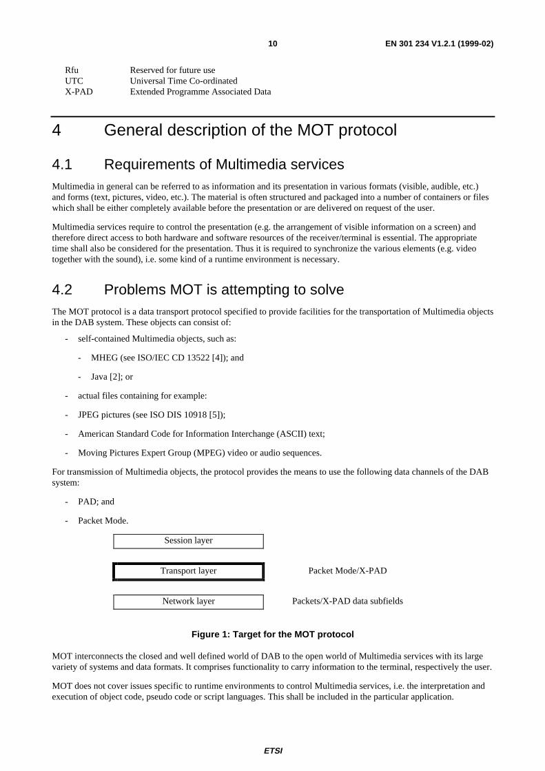
4.2 Problems MOT is attempting to solveThe MOT protocol is a data transport protocol specified to provide facilities for the transportation of Multimedia objectsin the DAB system. These objects can consist of:
- self-contained Multimedia objects, such as:
- MHEG (see ISO/IEC CD 13522 [4]); and
- Java [2]; or
- actual files containing for example:
- JPEG pictures (see ISO DIS 10918 [5]);
- American Standard Code for Information Interchange (ASCII) text;
- Moving Pictures Expert Group (MPEG) video or audio sequences.
For transmission of Multimedia objects, the protocol provides the means to use the following data channels of the DABsystem:
- PAD; and
- Packet Mode.
Session layer
Transport layer Packet Mode/X-PAD
Network layer Packets/X-PAD data subfields
Figure 1: Target for the MOT protocol
MOT interconnects the closed and well defined world of DAB to the open world of Multimedia services with its largevariety of systems and data formats. It comprises functionality to carry information to the terminal, respectively the user.
MOT does not cover issues specific to runtime environments to control Multimedia services, i.e. the interpretation andexecution of object code, pseudo code or script languages. This shall be included in the particular application.
ETSI
EN 301 234 V1.2.1 (1999-02)11
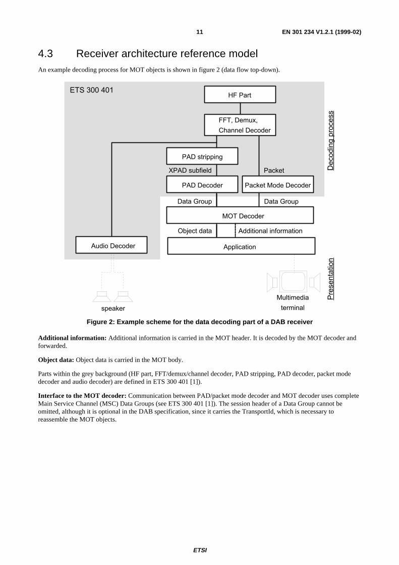
4.3 Receiver architecture reference modelAn example decoding process for MOT objects is shown in figure 2 (data flow top-down).
HF Part
FFT, Demux,
Channel Decoder
PAD stripping
Packet Mode DecoderPAD Decoder
MOT Decoder
Application
Deco
din
g p
roce
ssP
rese
nta
tion
PacketXPAD subfield
Data GroupData Group
Object data Additional information
speaker
Multimedia
terminal
Audio Decoder
ETS 300 401
Figure 2: Example scheme for the data decoding part of a DAB receiver
Additional information: Additional information is carried in the MOT header. It is decoded by the MOT decoder andforwarded.
Object data: Object data is carried in the MOT body.
Parts within the grey background (HF part, FFT/demux/channel decoder, PAD stripping, PAD decoder, packet modedecoder and audio decoder) are defined in ETS 300 401 [1]).
Interface to the MOT decoder: Communication between PAD/packet mode decoder and MOT decoder uses completeMain Service Channel (MSC) Data Groups (see ETS 300 401 [1]). The session header of a Data Group cannot beomitted, although it is optional in the DAB specification, since it carries the TransportId, which is necessary toreassemble the MOT objects.
ETSI
EN 301 234 V1.2.1 (1999-02)12
5 Object descriptionAn object consists of an ordered collection of the following three parts (see figure 3):
Header core: The header core contains information about the size and the content of the object, so that the receiver candetermine whether it has system resources to decode and present the object or not.
Header extension: The header extension includes information that supports the handling of the objects (e.g. memoryhandling) and provides additional information that can support an application.
Body: The body carries any kind of data, where structure and content of the data is described in the header core and theheader extension.
For transportation the object is split into several segments, at least one header segment and, if present, one bodysegment. Each segment is mapped into one Data Group as described in clause 6.
The header is separated from the body during transportation in order to:
- have the possibility to repeat the header several times before and during the transmission of the body (which isuseful when transmitting long objects);
- send the header in advance in order to give the receiver the opportunity to "be prepared in advance" to the datathat is going to be received;
- send the header unscrambled when the body is scrambled.
7 bytes variable variable
header core header extension body
Figure 3: General object structure
The header shall be sent at least once preceding the body of the object.
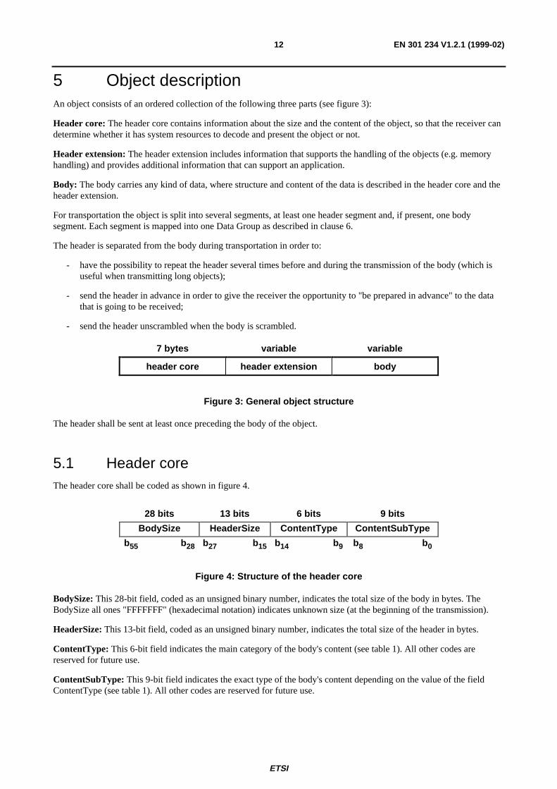
5.1 Header coreThe header core shall be coded as shown in figure 4.
28 bits 13 bits 6 bits 9 bits
BodySize HeaderSize ContentType ContentSubType
b55 b28 b27 b15 b14 b9 b8 b0
Figure 4: Structure of the header core
BodySize: This 28-bit field, coded as an unsigned binary number, indicates the total size of the body in bytes. TheBodySize all ones "FFFFFFF" (hexadecimal notation) indicates unknown size (at the beginning of the transmission).
HeaderSize: This 13-bit field, coded as an unsigned binary number, indicates the total size of the header in bytes.
ContentType: This 6-bit field indicates the main category of the body's content (see table 1). All other codes arereserved for future use.
ContentSubType: This 9-bit field indicates the exact type of the body's content depending on the value of the fieldContentType (see table 1). All other codes are reserved for future use.
ETSI
EN 301 234 V1.2.1 (1999-02)13
Table 1: ContentTypes and ContentSubTypes
ContentTypeb14 b9
ContentTypeInterpretation
ContentSubTypeb8 b0
ContentSubTypeInterpretation
000000 general data 000000000 Object Transfer000000001 MIME/HTTP [8], [9]
000001 text 000000000 Text (US ASCII) [10]000000001 Text (see ISO Latin 1) [6]000000010 HTML [3]
000010 image 000000000 GIF [11]000000001 JFIF [5]000000010 BMP [12]
000011 audio 000000000 MPEG I audio Layer I [13]000000001 MPEG I audio Layer II [13]000000010 MPEG I audio Layer III [13]000000011 MPEG II audio Layer I [14]000000100 MPEG II audio Layer II [14]000000101 MPEG II audio Layer III [14]000000110 uncompressed PCM audio [15]000000111 AIFF [16]000001000 ATRAC [17]000001001 ATRAC II [18]000001010 MPEG 4 audio [19]
000100 video 000000000 MPEG I video [20]000000001 MPEG II video [21]000000010 MPEG 4 video [22]000000011 H263 [23]
000101 MOT transport 000000000 Header update000110 system 000000000 MHEG [4]
000000001 Java [2]111111 proprietary table 000000000
...111111111
proprietary
5.2 Header extensionThe header extension consists of a list of different parameters identified by the related ParameterId field.These parameters describe several attributes of the object. Some of these parameters may occur more than once asdescribed separately for the different parameters.
The header extension is used to carry additional information about the object. Depending on the character of the objectthe header extension may contain parameters as listed in table 2.
ETSI
EN 301 234 V1.2.1 (1999-02)14
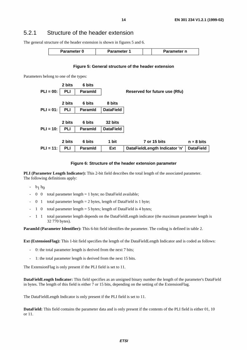
5.2.1 Structure of the header extension
The general structure of the header extension is shown in figures 5 and 6.
Parameter 0 Parameter 1 Parameter n
Figure 5: General structure of the header extension
Parameters belong to one of the types:
2 bits 6 bits
PLI = 00: PLI ParamId Reserved for future use (Rfu)
2 bits 6 bits 8 bits
PLI = 01: PLI ParamId DataField
2 bits 6 bits 32 bits
PLI = 10: PLI ParamId DataField
2 bits 6 bits 1 bit 7 or 15 bits n × 8 bits
PLI = 11: PLI ParamId Ext DataFieldLength Indicator 'n' DataField
Figure 6: Structure of the header extension parameter
PLI (Parameter Length Indicator): This 2-bit field describes the total length of the associated parameter.The following definitions apply:
- b1 b0
- 0 0 total parameter length = 1 byte; no DataField available;
- 0 1 total parameter length = 2 bytes, length of DataField is 1 byte;
- 1 0 total parameter length = 5 bytes; length of DataField is 4 bytes;
- 1 1 total parameter length depends on the DataFieldLength indicator (the maximum parameter length is 32 770 bytes).
ParamId (Parameter Identifier): This 6-bit field identifies the parameter. The coding is defined in table 2.
Ext (ExtensionFlag): This 1-bit field specifies the length of the DataFieldLength Indicator and is coded as follows:
- 0: the total parameter length is derived from the next 7 bits;
- 1: the total parameter length is derived from the next 15 bits.
The ExtensionFlag is only present if the PLI field is set to 11.
DataFieldLength Indicator: This field specifies as an unsigned binary number the length of the parameter's DataFieldin bytes. The length of this field is either 7 or 15 bits, depending on the setting of the ExtensionFlag.
The DataFieldLength Indicator is only present if the PLI field is set to 11.
DataField: This field contains the parameter data and is only present if the contents of the PLI field is either 01, 10or 11.
ETSI
EN 301 234 V1.2.1 (1999-02)15
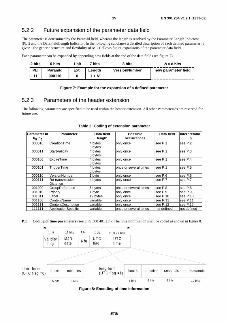
5.2.2 Future expansion of the parameter data field
The parameter is determined by the ParamId field, whereas the length is resolved by the Parameter Length Indicator(PLI) and the DataFieldLength Indicator. In the following subclause a detailed description of each defined parameter isgiven. The generic structure and flexibility of MOT allows future expansions of the parameter data field.
Each parameter can be expanded by appending new fields at the end of the data field (see figure 7).
2 bits 6 bits 1 bit 7 bits 8 bits N × 8 bits
PLI
11
ParamId
000110
Ext.
0
Length
1 + NVersionNumber new parameter field
Figure 7: Example for the expansion of a defined parameter
5.2.3 Parameters of the header extension
The following parameters are specified to be used within the header extension. All other ParameterIds are reserved forfuture use.
Table 2: Coding of extension parameter
Parameter Idb5 b0
Parameter Data fieldlength
Possibleoccurrences
Data field Interpretation
000010 CreationTime 4 bytes6 bytes
only once see P.1 see P.2
000011 StartValidity 4 bytes6 bytes
only once see P.1 see P.3
000100 ExpireTime 4 bytes6 bytes
only once see P.1 see P.4
000101 TriggerTime 4 bytes6 bytes
once or several times see P.1 see P.5
000110 VersionNumber 1 byte only once see P.6 see P.6000111 Re-transmission
Distance4 bytes only once see P.7 see P.7
001000 GroupReference 6 bytes once or several times see P.8 see P.8001010 Priority 1 byte only once see P.9 see P.9001011 Label 19 bytes only once see P.10 see P.10001100 ContentName variable only once see P.11 see P.11001111 ContentDescription variable only once see P.12 see P.12111111 ApplicationSpecific variable once or several times not defined not defined
P.1 Coding of time parameters (see ETS 300 401 [1]): The time information shall be coded as shown in figure 8.
5 b its 6 b its 6 b its 10 b its
Validityf lag
M J Ddate
U T Ct ime
U T Cflag
hours minutes mi l l isecondssecondshours minutesshort form(UTC f lag =0)
long form(UTC f lag =1)
Rfu
1 b it 17 b its 1 b it 1 b it 11 or 27 b its
5 b its 6 b its
Figure 8: Encoding of time information
ETSI
EN 301 234 V1.2.1 (1999-02)16
Validity flag: This bit is used to indicate whether the time and date information (UTC and MJD) carried in the timeparameters is valid or not as follows:
- Validity flag = 0: "Now"; MJD and UTC shall be ignored and be set to 0;
- Validity flag = 1: MJD and UTC are valid.
P.2 CreationTime: Authoring date of the object. The value of the parameter field is coded in the UTC format(see P1).
P.3 StartValidity: The received object is valid after the time indicated. The value of the parameter field is coded inthe UTC format (see P1).
P.4 ExpireTime: The received object is not valid anymore after the time indicated. The value of the parameter fieldis coded in the UTC format (see P1). If this parameter is not present the object is valid for an undefined period of time(up to the receiver). The object is not valid anymore after it expired and therefore it should not be presented anymore.
P.5 TriggerTime: This parameter specifies the time for when the presentation takes place. The TriggerTimeactivates the object according to its ContentType. The value of the parameter field is coded in the UTC format (see P1).
P.6 VersionNumber: If several versions of an object are transferred, this parameter indicates its VersionNumber.The parameter value is coded as an unsigned binary number, starting at 0 and being incremented by 1 modulo 256 eachtime the version changes. If the VersionNumber differs, the content of the body was modified.
P.7 RepetitionDistance: To support advanced caching of objects in the receiver, this parameter indicates aguaranteed maximum time until the next repetition of an object. The resolution in the time domain is 1/10 second toallow an exact synchronization, whereas the maximum time which can be indicated reaches up to 1 677 721 seconds(equal approx. 19 days, 10 hours and 2 minutes) for very slow repetition rates.
8 bits 24 bits
Rfa RepetitionDistance
Figure 9: Coding of the RepetitionDistance
P.8 GroupReference: A NumberOfObjects forming a logical entity can be managed using the GroupReference,which allows to identify all members of the group by a single identifier. The 32-bit GroupId can separate a large numberof groups in parallel or during a long time period. "Number of elements" equals "0" means undefined number ofelements. If this "Number of elements" parameter is explicitly given, each group can comprise max. 65 535 elements.
32 bits 16 bits
GroupId Number of elements
Figure 10: Coding of the GroupReference
P.9 Priority: The parameter is used to indicate the storage priority, i.e. in case of a "disk full" state only the objectshaving a high priority should be stored. It indicates the relevance of the content of the particular object for the service,i.e. a home page of a HTML based service has a high priority and should therefore not be deleted first, whereas pictures(e.g. buttons, etc.) are not as important as the home page and hence can be deleted first in case of a memory overflow.The possible values range from 0 = highest priority to 255 = lowest priority.
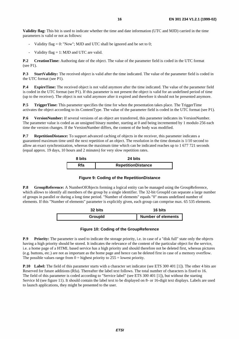
P.10 Label: The field of this parameter starts with a character set indicator (see ETS 300 401 [1]). The other 4 bits areReserved for future additions (Rfa). Thereafter the label text follows. The total number of characters is fixed to 16.The field of this parameter is coded according to "Service label" (see ETS 300 401 [1]), but without the startingService Id (see figure 11). It should contain the label text to be displayed on 8- or 16-digit text displays. Labels are usedto launch applications, they might be presented to the user.
ETSI
EN 301 234 V1.2.1 (1999-02)17
4 bits 4 bits 16 × 8 bits 16 bits
character setindicator
Rfa character field character flag field
b7 b4 b3 b0
Figure 11: Coding of the Label
P.11 ContentName: The DataField of this parameter starts with a one byte field, comprising a 4-bit character setindicator (see table 3) and a 4-bit Rfa field. The following character field contains a unique name or identifier for theobject. The total number of characters is determined by the DataFieldLength indicator minus one byte.
Hierarchical structures should use a slash "/" to separate different levels. No system specific restrictions shall be applied.Slashes forward inside the ContentName separate levels and slashes are not permitted for any other meaning than this.
Table 3: Character set indicator for the ContentName
b7 b4 Description0 0 0 0 complete EBU Latin based repertoire [25]0 0 0 1 EBU Latin based common core, Cyrillic, Greek [25]0 0 1 0 EBU Latin based core, Arabic, Hebrew, Cyrillic, Greek [25]0 0 1 1 ISO Latin Alphabet No 2 (see ISO-8859 Part 2 [7])0 1 0 0 ISO Latin Alphabet No 1 (see ISO-8859 Part 1 [6])
4 bits 4 bits (n - 1) bytes
character setindicator
Rfa character field
b7 b4 b3 b0
Figure 12: Coding of the ContentName and the ContentDescription
P.12 ContentDescription: The field of the parameter starts with a 4-bit character set indicator (see ETS 300 401 [1]).The other 4 bits are Reserved for future additions (Rfa). Afterwards the text describing the content of the object follows.This description shall be presented on receivers with limited display capabilities (i.e. text-only). The total number ofcharacters is determined by the DataFieldLength Indicator, decreased by the starting character set indicator (one byte).
ApplicationSpecific: This parameter field contains private parameters exclusively used by the application itself andtherefore no specification is required.
5.3 Object bodyThe object body contains the data to be transported (e.g. a file). The structure of the content of the object body isApplicationSpecific and not subject to standardization within the present document.
ETSI
EN 301 234 V1.2.1 (1999-02)18
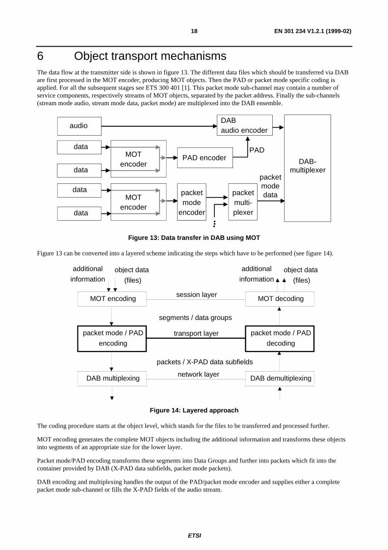
6 Object transport mechanismsThe data flow at the transmitter side is shown in figure 13. The different data files which should be transferred via DABare first processed in the MOT encoder, producing MOT objects. Then the PAD or packet mode specific coding isapplied. For all the subsequent stages see ETS 300 401 [1]. This packet mode sub-channel may contain a number ofservice components, respectively streams of MOT objects, separated by the packet address. Finally the sub-channels(stream mode audio, stream mode data, packet mode) are multiplexed into the DAB ensemble.
DABaudio encoder
audio
DAB-multiplexer
data
data
data PADPAD encoder
packet modedataMOT
encoder
packet mode
encoder
packet multi-plexer
� �� �� �
MOTencoder
data
Figure 13: Data transfer in DAB using MOT
Figure 13 can be converted into a layered scheme indicating the steps which have to be performed (see figure 14).
object data
(files)
MOT encoding
packet mode / PAD
encoding
DAB multiplexing
MOT decoding
packet mode / PAD
decoding
DAB demultiplexing
session layer
transport layer
network layer
additional
informationobject data
(files)
additional
information
segments / data groups
packets / X-PAD data subfields
Figure 14: Layered approach
The coding procedure starts at the object level, which stands for the files to be transferred and processed further.
MOT encoding generates the complete MOT objects including the additional information and transforms these objectsinto segments of an appropriate size for the lower layer.
Packet mode/PAD encoding transforms these segments into Data Groups and further into packets which fit into thecontainer provided by DAB (X-PAD data subfields, packet mode packets).
DAB encoding and multiplexing handles the output of the PAD/packet mode encoder and supplies either a completepacket mode sub-channel or fills the X-PAD fields of the audio stream.
ETSI
EN 301 234 V1.2.1 (1999-02)19
Subclauses 6.1, 6.2 and 6.3 describe the coding of data objects on the two layers below the object layer as well as thedifferent strategies to transfer the obtained packets or X-PAD data subfields in data channels.
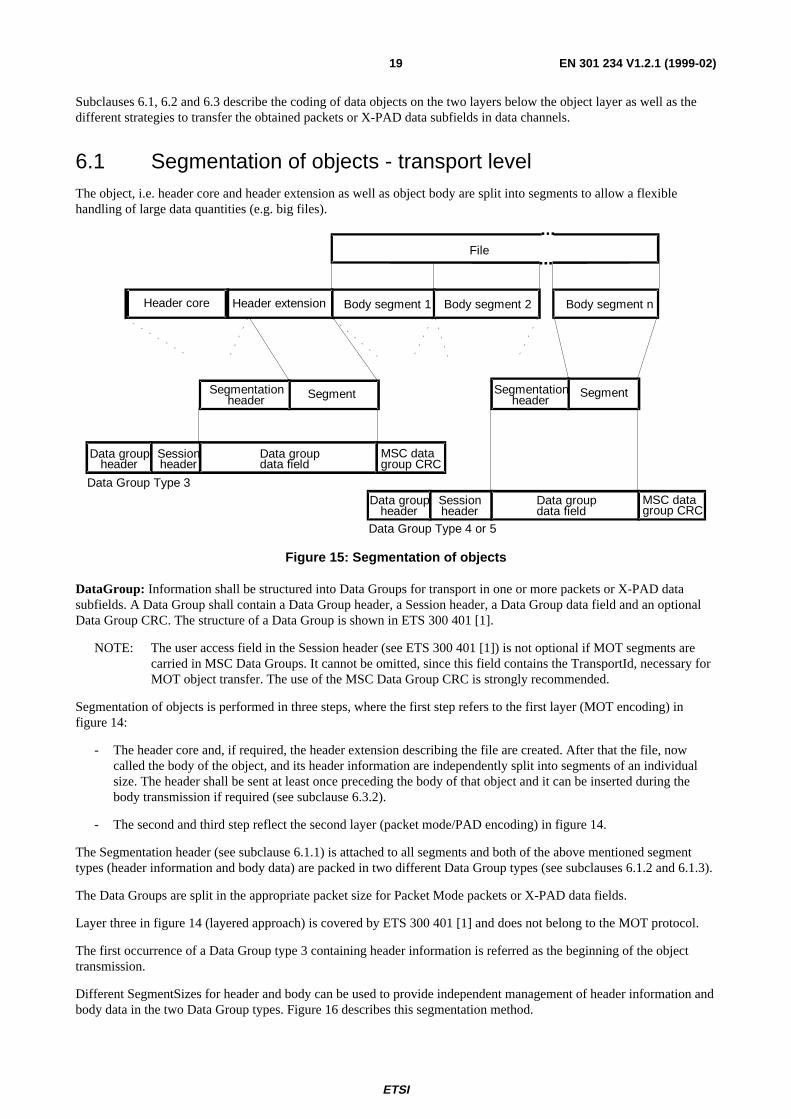
6.1 Segmentation of objects - transport levelThe object, i.e. header core and header extension as well as object body are split into segments to allow a flexiblehandling of large data quantities (e.g. big files).
Body segment 1
File
Data Group Type 3
Data groupdata field
Data Group Type 4 or 5
MSC datagroup CRC
Header extensionHeader core
Sessionheader
Data groupheader
Data groupdata field
Sessionheader
Data groupheader
Body segment 2 Body segment n
SegmentSegmentationheader
Segmentationheader
Segment
MSC datagroup CRC
Figure 15: Segmentation of objects
DataGroup: Information shall be structured into Data Groups for transport in one or more packets or X-PAD datasubfields. A Data Group shall contain a Data Group header, a Session header, a Data Group data field and an optionalData Group CRC. The structure of a Data Group is shown in ETS 300 401 [1].
NOTE: The user access field in the Session header (see ETS 300 401 [1]) is not optional if MOT segments arecarried in MSC Data Groups. It cannot be omitted, since this field contains the TransportId, necessary forMOT object transfer. The use of the MSC Data Group CRC is strongly recommended.
Segmentation of objects is performed in three steps, where the first step refers to the first layer (MOT encoding) infigure 14:
- The header core and, if required, the header extension describing the file are created. After that the file, nowcalled the body of the object, and its header information are independently split into segments of an individualsize. The header shall be sent at least once preceding the body of that object and it can be inserted during thebody transmission if required (see subclause 6.3.2).
- The second and third step reflect the second layer (packet mode/PAD encoding) in figure 14.
The Segmentation header (see subclause 6.1.1) is attached to all segments and both of the above mentioned segmenttypes (header information and body data) are packed in two different Data Group types (see subclauses 6.1.2 and 6.1.3).
The Data Groups are split in the appropriate packet size for Packet Mode packets or X-PAD data fields.
Layer three in figure 14 (layered approach) is covered by ETS 300 401 [1] and does not belong to the MOT protocol.
The first occurrence of a Data Group type 3 containing header information is referred as the beginning of the objecttransmission.
Different SegmentSizes for header and body can be used to provide independent management of header information andbody data in the two Data Group types. Figure 16 describes this segmentation method.
ETSI
EN 301 234 V1.2.1 (1999-02)20
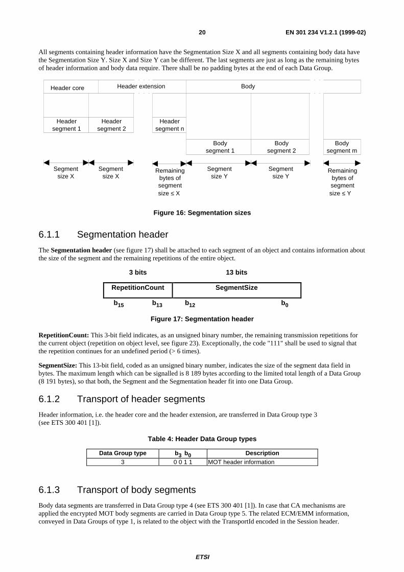
All segments containing header information have the Segmentation Size X and all segments containing body data havethe Segmentation Size Y. Size X and Size Y can be different. The last segments are just as long as the remaining bytesof header information and body data require. There shall be no padding bytes at the end of each Data Group.
Header core Header extension Body
Bodysegment 2
Headersegment 1
Headersegment 2
Headersegment n
Bodysegment 1
Bodysegment m
Segmentsize X
Segmentsize X
Segmentsize Y
Segmentsize Y
Remainingbytes ofsegmentsize ≤ X
Remainingbytes ofsegmentsize ≤ Y
Figure 16: Segmentation sizes
6.1.1 Segmentation header
The Segmentation header (see figure 17) shall be attached to each segment of an object and contains information aboutthe size of the segment and the remaining repetitions of the entire object.
3 bits 13 bits
RepetitionCount SegmentSize
b15 b13 b12 b0
Figure 17: Segmentation header
RepetitionCount: This 3-bit field indicates, as an unsigned binary number, the remaining transmission repetitions forthe current object (repetition on object level, see figure 23). Exceptionally, the code "111" shall be used to signal thatthe repetition continues for an undefined period (> 6 times).
SegmentSize: This 13-bit field, coded as an unsigned binary number, indicates the size of the segment data field inbytes. The maximum length which can be signalled is 8 189 bytes according to the limited total length of a Data Group(8 191 bytes), so that both, the Segment and the Segmentation header fit into one Data Group.
6.1.2 Transport of header segments
Header information, i.e. the header core and the header extension, are transferred in Data Group type 3(see ETS 300 401 [1]).
Table 4: Header Data Group types
Data Group type b 3 b0 Description3 0 0 1 1 MOT header information
6.1.3 Transport of body segments
Body data segments are transferred in Data Group type 4 (see ETS 300 401 [1]). In case that CA mechanisms areapplied the encrypted MOT body segments are carried in Data Group type 5. The related ECM/EMM information,conveyed in Data Groups of type 1, is related to the object with the TransportId encoded in the Session header.
ETSI
EN 301 234 V1.2.1 (1999-02)21
Table 5: Body Data Group types
Data Group type b 3 b0 Description4 0 1 0 0 MOT data5 0 1 0 1 MOT data and CA parameters
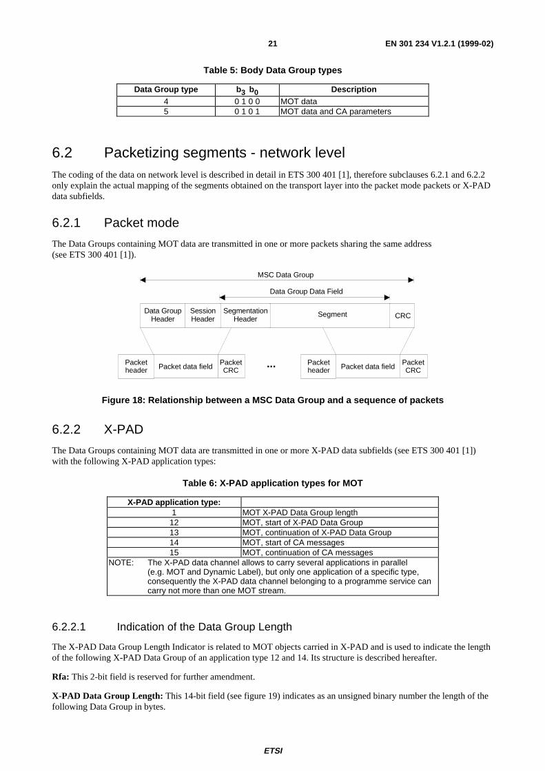
6.2 Packetizing segments - network levelThe coding of the data on network level is described in detail in ETS 300 401 [1], therefore subclauses 6.2.1 and 6.2.2only explain the actual mapping of the segments obtained on the transport layer into the packet mode packets or X-PADdata subfields.
6.2.1 Packet mode
The Data Groups containing MOT data are transmitted in one or more packets sharing the same address(see ETS 300 401 [1]).
MSC Data Group
Segment CRCSegmentation
HeaderSessionHeader
Data GroupHeader
Packet data field PacketCRC
Packetheader Packet data field Packet
CRCPacketheader
...
Data Group Data Field
Figure 18: Relationship between a MSC Data Group and a sequence of packets
6.2.2 X-PAD
The Data Groups containing MOT data are transmitted in one or more X-PAD data subfields (see ETS 300 401 [1])with the following X-PAD application types:
Table 6: X-PAD application types for MOT
X-PAD application type:1 MOT X-PAD Data Group length
12 MOT, start of X-PAD Data Group13 MOT, continuation of X-PAD Data Group14 MOT, start of CA messages15 MOT, continuation of CA messages
NOTE: The X-PAD data channel allows to carry several applications in parallel(e.g. MOT and Dynamic Label), but only one application of a specific type,consequently the X-PAD data channel belonging to a programme service cancarry not more than one MOT stream.
6.2.2.1 Indication of the Data Group Length
The X-PAD Data Group Length Indicator is related to MOT objects carried in X-PAD and is used to indicate the lengthof the following X-PAD Data Group of an application type 12 and 14. Its structure is described hereafter.
Rfa: This 2-bit field is reserved for further amendment.
X-PAD Data Group Length: This 14-bit field (see figure 19) indicates as an unsigned binary number the length of thefollowing Data Group in bytes.
ETSI
EN 301 234 V1.2.1 (1999-02)22
CRC: A checksum is calculated over the Rfa and the X-PAD Data Group Length field according to the polynomial:
G(x) = x16 + x12 + x5 + 1
The initial state of the shift register is all bits set to 1. The CRC word shall be complemented (1's complement) prior totransmission.
2 bits 14 bits 16 bits
Rfa X-PAD Data Group Length CRC
Figure 19: Coding of the X-PAD Data Group Length
The X-PAD Data Group length covers the Data Group header, the session header, the Data Group data field and theoptional CRC, if present (see figure 20).
data group header session header data group data field optional CRC
X-PAD Data Group Length
Figure 20: Length of the Data Group
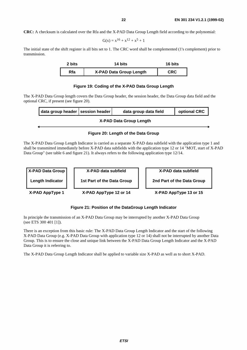
The X-PAD Data Group Length Indicator is carried as a separate X-PAD data subfield with the application type 1 andshall be transmitted immediately before X-PAD data subfields with the application type 12 or 14 "MOT, start of X-PADData Group" (see table 6 and figure 21). It always refers to the following application type 12/14.
X-PAD Data Group
Length Indicator
X-PAD data subfield
1st Part of the Data Group
X-PAD data subfield
2nd Part of the Data Group
X-PAD AppType 1 X-PAD AppType 12 or 14 X-PAD AppType 13 or 15
Figure 21: Position of the DataGroup Length Indicator
In principle the transmission of an X-PAD Data Group may be interrupted by another X-PAD Data Group(see ETS 300 401 [1]).
There is an exception from this basic rule: The X-PAD Data Group Length Indicator and the start of the followingX-PAD Data Group (e.g. X-PAD Data Group with application type 12 or 14) shall not be interrupted by another DataGroup. This is to ensure the close and unique link between the X-PAD Data Group Length Indicator and the X-PADData Group it is referring to.
The X-PAD Data Group Length Indicator shall be applied to variable size X-PAD as well as to short X-PAD.
ETSI
EN 301 234 V1.2.1 (1999-02)23
MSC Data Group
Segment CRCSegmentation
HeaderSessionHeader
Data GroupHeader
X-PAD DataSubfield
X-PAD DataSubfield
...
Data GroupLength Indicator
Application Type 12 or 14
Application Type 1
Application Type 13 or 15
X-PAD DataSubfield
Application Type 1
X-PAD DataSubfield
X-PAD DataSubfield
Application Type 13 or 15
...
Data Group Data Field
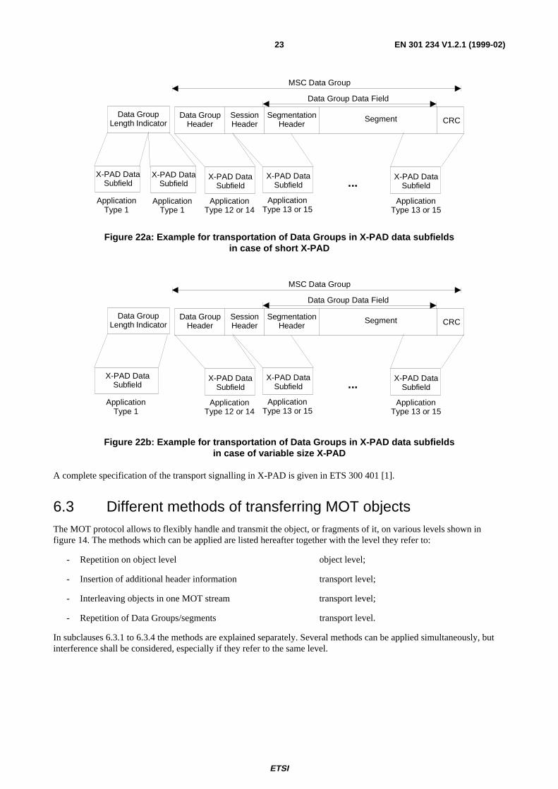
Figure 22a: Example for transportation of Data Groups in X-PAD data subfieldsin case of short X-PAD
MSC Data Group
Segment CRCSegmentation
HeaderSessionHeader
Data GroupHeader
X-PAD DataSubfield
X-PAD DataSubfield
...
Data GroupLength Indicator
Application Type 12 or 14
Application Type 13 or 15
Application Type 1
X-PAD DataSubfield
X-PAD DataSubfield
Application Type 13 or 15
...
Data Group Data Field
Figure 22b: Example for transportation of Data Groups in X-PAD data subfieldsin case of variable size X-PAD
A complete specification of the transport signalling in X-PAD is given in ETS 300 401 [1].
6.3 Different methods of transferring MOT objectsThe MOT protocol allows to flexibly handle and transmit the object, or fragments of it, on various levels shown infigure 14. The methods which can be applied are listed hereafter together with the level they refer to:
- Repetition on object level object level;
- Insertion of additional header information transport level;
- Interleaving objects in one MOT stream transport level;
- Repetition of Data Groups/segments transport level.
In subclauses 6.3.1 to 6.3.4 the methods are explained separately. Several methods can be applied simultaneously, butinterference shall be considered, especially if they refer to the same level.
ETSI
EN 301 234 V1.2.1 (1999-02)24
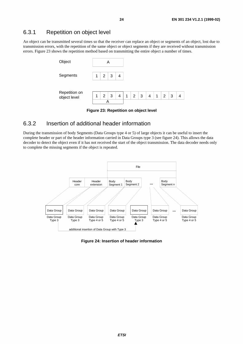
6.3.1 Repetition on object level
An object can be transmitted several times so that the receiver can replace an object or segments of an object, lost due totransmission errors, with the repetition of the same object or object segments if they are received without transmissionerrors. Figure 23 shows the repetition method based on transmitting the entire object a number of times.
Object
Segments 1 2 3 4
Repetition on object level 1 2 3 4 1 2 3 4 1 2 3 4
A
A
Figure 23: Repetition on object level
6.3.2 Insertion of additional header information
During the transmission of body Segments (Data Groups type 4 or 5) of large objects it can be useful to insert thecomplete header or part of the header information carried in Data Groups type 3 (see figure 24). This allows the datadecoder to detect the object even if it has not received the start of the object transmission. The data decoder needs onlyto complete the missing segments if the object is repeated.
Body Segment 1
File
Data Group Type 3
Data Group
Headerextension
Headercore
Data Group Type 3
Data Group
Data Group Type 4 or 5
Data Group
Data Group Type 4 or 5
Data Group
Data Group Type 3
Data Group
Data Group Type 4 or 5
Data Group
Data Group Type 4 or 5
Data Group
additional insertion of Data Group with Type 3
Body Segment 2
Body Segment n...
...
Figure 24: Insertion of header information
ETSI
EN 301 234 V1.2.1 (1999-02)25
6.3.3 Interleaving objects in one MOT stream
Transfer of Data Groups of different MOT objects in parallel.
With the MOT protocol it is possible to transmit several objects in parallel in one single data channel (i.e. in one X-PADapplication or with one Packet Address). The different objects are separated by their TransportId (see ETS 300 401 [1]).
Data GroupTransport Id x
Data GroupTransport Id y
Data GroupTransport Id x
Data GroupTransport Id z
Data GroupTransport Id x
Data GroupTransport Id y
Object YObject Z
Object X
Figure 25: Interleaving Data Groups
6.3.4 Repetition of Data Groups/segments
Segments of an object can be transmitted several times so that the receiver can replace those segments, lost due totransmission errors, with the repetition of the same object segments received without errors. Figure 26 shows therepetition method based on transmitting every segment of an object a number of times.
Object
Segments 1 2 3 4
Repetition on segment level 1 1 1 2 2 3 3 4 43 43
A
Figure 26: Repetition of Data Groups/segments
7 Updating
7.1 Object updateAn object is replaced by a new version of the same object, e.g. because the content may have changed.The ContentName of the object which replaces an already existing one shall be the same as the substituted object.An object cannot be partly updated since MOT just handles the object as an entity. The following parameters are used tomanage an update:
ContentName: This parameter is used to link the update to the object to be updated.
VersionNumber: Each time a complete object is updated its VersionNumber shall be incremented by 1 modulo 256.
ETSI
EN 301 234 V1.2.1 (1999-02)26
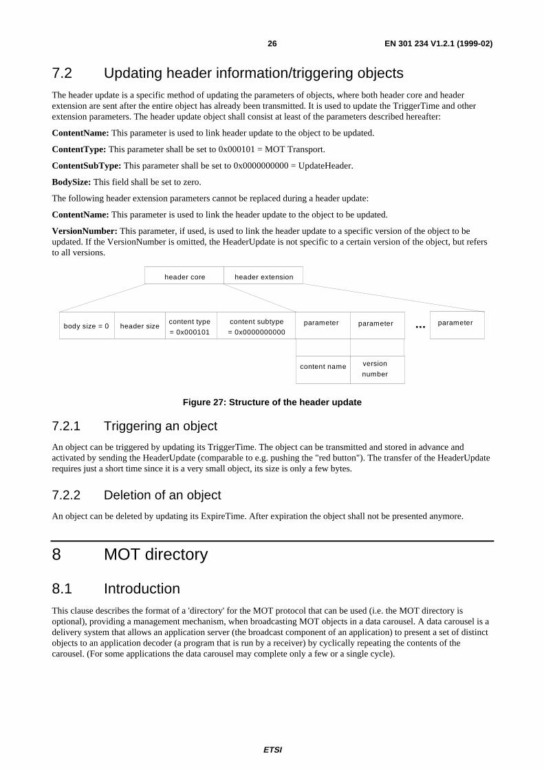
7.2 Updating header information/triggering objectsThe header update is a specific method of updating the parameters of objects, where both header core and headerextension are sent after the entire object has already been transmitted. It is used to update the TriggerTime and otherextension parameters. The header update object shall consist at least of the parameters described hereafter:
ContentName: This parameter is used to link header update to the object to be updated.
ContentType: This parameter shall be set to 0x000101 = MOT Transport.
ContentSubType: This parameter shall be set to 0x0000000000 = UpdateHeader.
BodySize: This field shall be set to zero.
The following header extension parameters cannot be replaced during a header update:
ContentName: This parameter is used to link the header update to the object to be updated.
VersionNumber: This parameter, if used, is used to link the header update to a specific version of the object to beupdated. If the VersionNumber is omitted, the HeaderUpdate is not specific to a certain version of the object, but refersto all versions.
header core header extension
body size = 0 header sizecontent type
= 0x000101
content subtype
= 0x0000000000parameter parameter...
version
number
parameter
content name
Figure 27: Structure of the header update
7.2.1 Triggering an object
An object can be triggered by updating its TriggerTime. The object can be transmitted and stored in advance andactivated by sending the HeaderUpdate (comparable to e.g. pushing the "red button"). The transfer of the HeaderUpdaterequires just a short time since it is a very small object, its size is only a few bytes.
7.2.2 Deletion of an object
An object can be deleted by updating its ExpireTime. After expiration the object shall not be presented anymore.
8 MOT directory
8.1 IntroductionThis clause describes the format of a 'directory' for the MOT protocol that can be used (i.e. the MOT directory isoptional), providing a management mechanism, when broadcasting MOT objects in a data carousel. A data carousel is adelivery system that allows an application server (the broadcast component of an application) to present a set of distinctobjects to an application decoder (a program that is run by a receiver) by cyclically repeating the contents of thecarousel. (For some applications the data carousel may complete only a few or a single cycle).
ETSI
EN 301 234 V1.2.1 (1999-02)27
Within a data carousel, a directory is used to provide a complete description of the contents of the carousel (i.e. theheaders of the objects), together with sufficient information to find the data for each described object. Version controlmechanisms applied both to the objects within the carousel and the directory itself provides the ability to correctlymanage updates to the carousel with minimum effort and at all times ensure that the correct version of an object is usedby the application.
If an application requests a particular object, the receiver can easily determine by looking in the directory a) whether ornot the requested objects exists within the carousel and b) where to find the object data. If the object the applicationrequests is not stored in the receiver it may simply wait for the next time that the object is broadcast. If desired, thereceiver may optionally implement caching strategies to reduce the latency of accesses by the application decoder andimprove the performance of the carousel.
8.1A Assembly of MOT objects and MOT directoryMOT transfers objects by dividing both their headers and bodies into fixed length segments and then transferring eachsegment within an MOT data group. In order to reassemble each object (with body and header), the MOT decoder usesa TransportId and a SegmentNumber carried in the Session Header field of the data group to identify which segment ofwhich object the data group is carrying. The TransportId is a unique identifier for the object within the carousel and isalso used to provide version management of the data. Whenever the data for an object changes, the TransportId is alsochanged. The mechanism for assembling the MOT directory is identical.
8.2 MOT directory codingThe MOT directory is the table of contents for the MOT data carousel and is the mechanism for controlling access to theobjects. Any request for an object can be processed by looking up the object in the MOT directory and using thedirectory to identify the TransportId of the desired object. The directory is also the key to managing version control ofobjects within the MOT carousel; if the TransportId of the directory changes, the contents of the carousel should havechanged and a simple examination of the directory can identify all the objects that have changed.
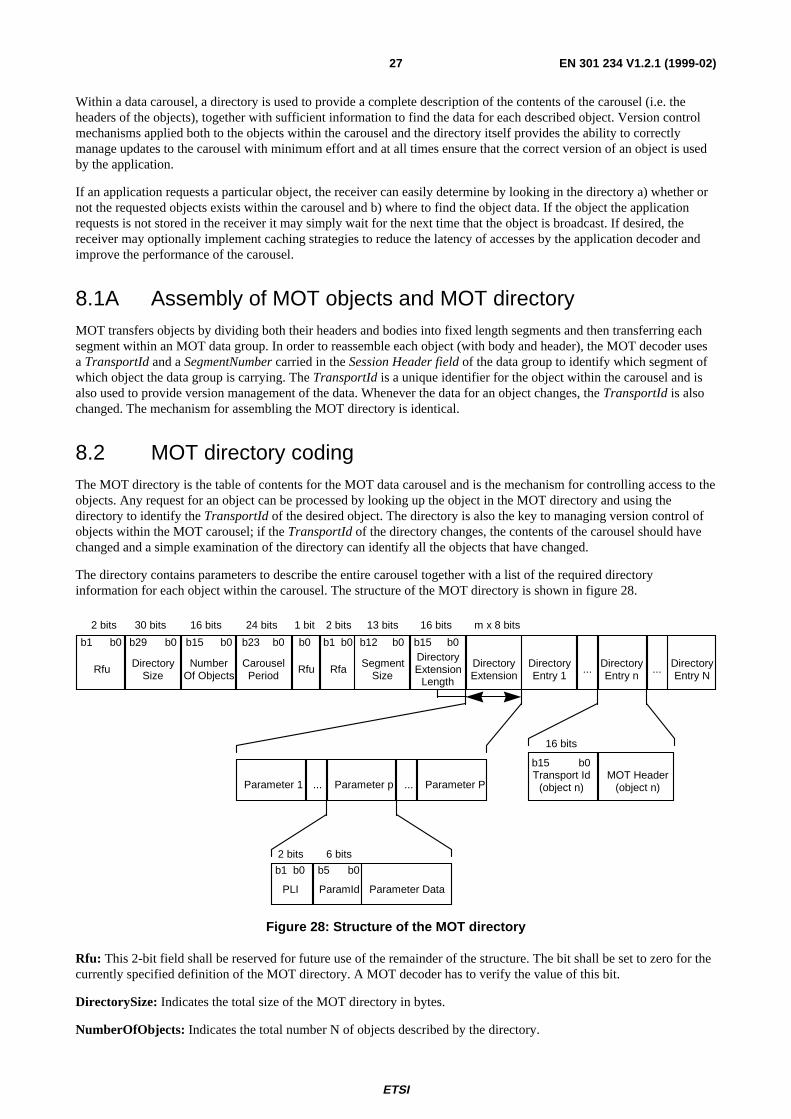
The directory contains parameters to describe the entire carousel together with a list of the required directoryinformation for each object within the carousel. The structure of the MOT directory is shown in figure 28.
b15 b0
NumberOf Objects
16 bits
b1 b0
Rfa
2 bits
b23 b0
CarouselPeriod
24 bits
SegmentSize
13 bits
b12 b0DirectoryExtension
Length
16 bits
b0b15
... DirectoryEntry n
... DirectoryEntry N
DirectoryEntry 1
DirectoryExtension
m x 8 bits
b15 b0Transport Id
(object n)
16 bits
MOT Header(object n)
Rfu
1 bit
b0
Parameter 1 Parameter p Parameter P... ...
b1 b0
PLI
2 bits
ParamId
6 bits
b5 b0
Parameter Data
b29 b0
DirectorySize
30 bits
b1 b0
Rfu
2 bits
Figure 28: Structure of the MOT directory
Rfu: This 2-bit field shall be reserved for future use of the remainder of the structure. The bit shall be set to zero for thecurrently specified definition of the MOT directory. A MOT decoder has to verify the value of this bit.
DirectorySize: Indicates the total size of the MOT directory in bytes.
NumberOfObjects: Indicates the total number N of objects described by the directory.
ETSI
EN 301 234 V1.2.1 (1999-02)28
CarouselPeriod: Indicates the maximum time in tenths of a second for the carousel to complete a cycle. It is the longesttime taken for any object in the carousel to be repeated in the transmitted signal. A value of 0 shall indicate that theCarouselPeriod is undefined.
NOTE: This is the case if the carousel only makes one turn or the bit-rate changes dynamically.
Rfu: This 1-bit field shall be reserved for future use of the remainder of the structure. The bit shall be set to zero for thecurrently specified definition of the MOT directory. A MOT decoder has to verify the value of this bit.
Rfa: This 2-bit field shall be reserved for future additions. The bits shall be set to zero until they are defined.
SegmentSize: Indicates the SegmentSize in bytes that will be used for the segmentation of objects within the MOTcarousel. A value of 0 indicates that objects within the carousel may have different segmentation sizes. The last segmentof an object may be smaller than this SegmentSize.
DirectoryExtensionLength: Indicates the total number of following DirectoryExtension bytes.
DirectoryExtension: Carries a list of parameters which are used to describe the entire carousel. The structure of theseparameters is as defined for the MOT header extension parameters (cf. 5.2.1).
TransportId: Identifies the object to which the following MOT header refers (cf. 8.1.1).
MOT Header: Carries the header core and header extension of the object. The coding structure is exactly the same forMOT headers in data groups of type 6 (i.e. in the MOT directory ) and in data groups of type 3 (i.e. in a separate MOTheader, cf. 5.1 and 5.2). If a parameter of the header extension (for example CreationTime) appears in both the MOTdirectory and the separate MOT header in an MOT-stream, the entries in both places have to be identical, to ensureconsistency of the parameters. This is also true if a parameter holds several parameter entries of that type. It is howevernot mandatory that a parameter type of the header extension, that is optional to both the MOT directory and the separateMOT header, is present both in the MOT directory and the separate MOT header. In particular this concerns thoseparameter types relevant for the object transfer (e.g., the ExpireTime parameter is not useful in the MOT directory but inthe MOT header). The separate MOT object headers and the extension parameters of the MOT directory shallindependently provide the application decoder with complete information.
8.2.1 Parameters of the DirectoryExtension
Parameters in the MOT header are used to describe objects within the carousel. A number of different parameters areavailable but the way in which they are used to access the carousel is defined by the application that is supported by theMOT carousel. For a large number of applications, the content name parameter will be the access point for objects.
Within the DirectoryExtension field, the permitted parameters types are defined in Table 7.
Table 7: DirectoryExtension parameters
ParamId Description0x00 - 0x1f Reserved for MOT0x20 - 0x3f ApplicationSpecific
8.2.2 SegmentSize of the MOT directory
For ordinary objects within an MOT carousel, the segmentation size may be already known by the MOT decoder fromthe directory, but the size of segments for the directory cannot be known before they are received.
ETSI
EN 301 234 V1.2.1 (1999-02)29
8.2.3 Identification of the MOT directory
The directory is the key to accessing any object within the carousel and so it shall be possible for a MOT decoder tofilter for the directory easily. Within an MOT stream that contains a directory the following rules apply:
- For each carousel of objects there shall be one directory that describes all objects within the carousel.
- An MOT stream shall contain at most one carousel.
In order to provide easy and effective filtering for the directory, a particular data group type shall be used - Type 6:MOT directory. To identify the MOT directory, the MOT decoder should filter for the directory by looking for datagroups with a type value of 6. Because there can only ever be one directory within the stream of data groups, this canalways be done unambiguously. Once acquired, changes to the directory can always be detected by looking for changesin the TransportId of the MOT directory.
NOTE: The MOT directory is an entity of its own, i.e. different to MOT objects, it is not split in header and body.
8.3 Use of the MOT directory
8.3.1 Segment reception order
The order in which MOT segments are received is unimportant - the SegmentNumber and TransportId fields of eachsegment allow accurate reconstruction of the MOT directory (and of each object) regardless of when the individualsegments are received.
8.3.2 Service acquisition
The key to acquiring a service broadcast in a carousel is reception of the MOT directory. Once this has been received,the complete structure and contents of the carousel is known, even if the data for the objects themselves has not yet beenreceived. If the scope of the carousel is known, the receiver has all the information it requires to process requests for anobject from an application - it knows whether or not a requested object exists within the carousel and how to identify theobject when it is broadcast.
The MOT decoder can always determine the correct contents of the carousel by examining the current directory - thereis no need for a MOT decoder to have any knowledge about previously broadcast information in order to correctlydecode the current carousel.
If the MOT decoder does not directly receive a MOT directory (some data carousels may appear with a largeNumberOfObjects and therefore the MOT directory can not be sent often enough, due to overhead, to give short accesstime) it could at first reassemble objects making use of MOT headers (in data group type 3) of those objects. By this itcan build up a list of objects that have been reassembled. When the MOT decoder has identified and reassembled anMOT directory, at which point the objects will be completely described, it should base its continued receiving strategyon the MOT directory instead of the MOT headers. It can then compare the objects already reassembled and storedbefore the appearance of the MOT directory and decide on whether to keep them or not.
The MOT decoder is not restricted concerning making use of both the MOT directory and the MOT headers at the sametime in its receiving strategy. It is however strongly recommended that the receiving strategy is based solely on the MOTdirectory, if present (note that the use of the MOT directory is optional).
ETSI
EN 301 234 V1.2.1 (1999-02)30
8.3.3 Version control
The use of a data carousel implies an application data set that is essentially static - it should be unlikely that the datacarried in the carousel will change rapidly. However, the data may well need to change and it is important that a MOTdecoder is able to detect when the carousel has changed so that it can properly manage any cached data, if applicable.
Each object in the carousel has a TransportId assigned to it which is carried both in the object segments (for verificationand identification) and in the MOT directory (for carousel management). If any object in the carousel is changed(segmentation, header or body), a new TransportId shall be assigned. This requires a change to the directory and so theTransportId of the directory shall also be changed to reflect this - any change to the carousel can be detected merely bychecking for changes in the TransportId of the MOT directory.
8.3.4 Allocation of TransportIds
The TransportId field is used to uniquely identify a specific instance of an object. In order to minimize the risk ofconfusion for the MOT decoder when rapid updates are taking place, broadcast servers should ensure that TransportIdsare not re-used until all other available TransportIds have been used.
NOTE: The TransportId is used solely for the purpose of identifying the object during transport - it has noapplication significance whatsoever.
8.3.5 Prioritizing objects within the carousel
Because the transmission order of objects (and also their segments) within the carousel is unimportant, it follows thatobjects which have more significance than others to the application may be repeated within one turn of the carousel, inorder that the acquisition time for these objects is minimized. In particular, the directory may be treated in this way as itis central to being able to access the objects within the carousel.
NOTE: The Re-transmission Distance may be used to indicate the guaranteed maximum time until individualobjects appear again within the overall carousel, as this may differ from the period of the entire carousel(which is defined as the longest repetition period for any object in the carousel).
8.3.6 Managing updates to the carousel
When the carousel is changed there is no requirement to complete either the current cycle of the carousel or the currentobject. As soon as a MOT decoder detects a change to the directory, it should use the information in the directory todetermine whether or not any cached data is still valid.
8.3.7 Cache management
It is possible for the broadcast server to indicate to the MOT decoder which objects have the greatest importance to theservice at the transport level. This can be done through the use of the priority parameter.
ETSI
EN 301 234 V1.2.1 (1999-02)31
HistoryDocument history
V1.1.1 January 1998 Publication
V1.2.1 September 1998 One-step Approval Procedure OAP 9904: 1998-09-25 to 1999-01-22
V1.2.1 February 1999 Publication
ISBN 2-7437-2875-2Dépôt légal : Février 1999
Related Documents


![Protocol Oblivious Classification of Multimedia TrafficPROTOCOL OBLIVIOUS CLASSIFICATION OF MULTIMEDIA TRAFFIC 3 standard H.323 protocol [2]. It identifies voice traffic by first](https://static.cupdf.com/doc/110x72/5e71781b3c47f520bd433007/protocol-oblivious-classiication-of-multimedia-trafic-protocol-oblivious-classification.jpg)