management MEDIA HEALTH law DESIGN EDUCATION MUSIC agriculture LANGUAGE MECHANICS psychology BIOTECHNOLOGY GEOGRAPHY ART PHYSICS history E C O L O G Y CHEMISTRY mathematics ENGINEERING MULTIMEDIA

Welcome message from author
This document is posted to help you gain knowledge. Please leave a comment to let me know what you think about it! Share it to your friends and learn new things together.
Transcript

managementMEDIAHEALTH
lawD
ESIGN
EDU
CAT
ION
MU
SICagriculture
LA
NG
UA
GEM E C H A N I C S
psychology
BIOTECHNOLOGY
GEOGRAPHY
ARTPHYSICS
history
ECOLOGY
CHEMISTRY
math
ematicsENGINEERING
MULTIMEDIA
Subject: MULTIMEDIA Credits: 4
SYLLABUS
Basics of Multimedia
Technology, Computers, Communication and Entertainment: Multimedia -An introduction: Framework for
multimedia systems; multimedia devices CD Audio. CD-ROM. CD-I: presentation devices and the user
interface; multimedia presentation and authoring; professional development tools: LANs & multimedia.
Internet, World Wide Web & Multimedia; distribution network ATM & ADSL; multimedia servers &
databases: vector graphics; 3-D graphics programs; animation techniques; shading; anti -aliasing; morphing:
video on demand
Image Compression & Standards
Making still images: editing and capturing images; scanning images; computer color models: color palettes;
vector drawing; 3 -D drawing and rendering; JPEG-objectives and architecture: JPEG-DCT encoding and
quantization, JPEG statistical coding; JPEG predictive loss less coding; JPEG performance; Overview of other
image file formats as GIF, TIFF. BMP. PNG etc.
Audio & Video
Digital representation of sound: time domain sampled representation; method of encoding the analog signals;
sub-band coding; Fourier method: transmission of digital sound; digital audio signal processing; stereophonic &
quadraphonic signal processing; editing sampled sound:
MPEG Audio
Audio compression & decompression: brief survey of speech recognition and generation; audio synthesis;
Musical Instrument Digital Interface (MIDI); digital video and image Compression; MPEG Motion video
compression standard; DVI technology: time based media representation and delivery.
Virtual Reality
Applications of multimedia, Intelligent multimedia system, Desktop Virtual Reality (VR). VR operating
System, Virtual environment displays and orientation tracking; visually coupled system requirements;
intelligent VR software systems. Applications of environments in various fields viz. Entertainment.
manufacturing. Business, education, etc.
Suggested Readings:
1. Multimedia: An Introduction, Villamil & Molina, PHI.
2. Sound & Video, Lozano. Multimedia, PHI.
3. Multimedia: Production. Planning and Delivery, Villamil & Molina, PHI
4. Multimedia on the Pc, Sinclair, BPB.
CHAPTER 1
BASICS OF MULTIMEDIA
Multimedia
• When different people mention the term multimedia, they often have quite different, or even
opposing, viewpoints.
– A PC vendor: a PC that has sound capability, a DVD-ROM drive, and perhaps the
superiority of multimedia-enabled microprocessors that understand additional multimedia
instructions.
– A consumer entertainment vendor: interactive cable TV with hundreds of digital channels
available, or a cable TV-like service delivered over a high-speed Internet connection.
– A Computer Science (CS) student: applications that use multiple modalities, including text,
images, drawings (graphics), animation, video, sound including speech, and interactivity.
• Multimedia and Computer Science:
– Graphics, HCI, visualization, computer vision, data compression, graph theory, networking,
database systems. Multimedia and Hypermedia.
Components of Multimedia
• Multimedia involves multiple modalities of text, audio, images, drawings, animation, and
video.
Examples of how these modalities are put to use:
1.Video teleconferencing.
2.Distributed lectures for higher education.
3.Tele-medicine.
4.Co-operative work environments.
5.Searching in (very) large video and image databases for target visual objects.
6.―Augmented‖ reality: placing real-appearing computer graphics and video objects into
scenes.
7.Including audio cues for where video-conference participants are located.
8.Building searchable features into new video, and enabling very high- to very low-bit-rate
use of new, scalable multimedia products.
9.Making multimedia components editable.
10.Building ―inverse-Hollywood‖ applications that can recreate the process by which a video
was made.
11.Using voice-recognition to build an interactive environment, say a kitchen-wall web
browser.
1) Introduction to Multimedia Technology
a) Multimedia: Any combination of texts, graphics, animation, audio and video which is a
result of computer based technology or other electronic media.
i) Features of Multimedia:
(1) Interactivity: When the end‐user is able to control the elements of media that are
required, and subsequently obtains the required information in a non‐linear way
(2) Navigation: Enables the user to explore and navigate from one web page to another.
(3) Hyperlink: Non‐linear navigation of ―jumping‖ for the required information.
(4) Easy to use, Easy to understand:
ii) Types of Multimedia:
(1) Text: The basic element for all multimedia applications. Directly informs the user about
the information that it wishes to convey.
(2) Graphics: Pictures as visuals in digital form used in multimedia presentations. There are
two types of graphics:
(a) Bitmap Graphics (Image Raster): Formed by pixels arranged in specific ways in a
matrix form
(b) Vector Graphics: Formed by lines that follow mathematical equations called vector.
(3) Animation: Process of adding movements to static images through various methods.
(4) Audio: Sound in Digital form used in Multimedia Presentations.
(5) Video: Video in digital form in Multimedia Presentations
2) Multimedia Technology Applications
a) Video Teleconferencing: Transmission of synchronised video and audio in real‐time
through computer networks in between two or more multipoints (or participants) separated by
locations.
Advantages Disadvantages
Reduces travelling cost and saves time;
Increases productivity and improves the quality of teaching and learning;
Make quick and spontaneous decisions;
Increases satisfaction in teaching or at the workplace
Video requires more bandwidth than audio. Therefore, Video teleconferencing is
expensive. (Use Video compression to solve)
Requires a network to support short‐delay as audio and video are asynchronous and it is
realtime. (Use Optimum multimedia network; fibre optics or ISDN)
b) Multimedia Store and Forward Mail: Allow users to generate, modify and receive
documents that contain multimedia. Eg. Gmail, Hotmail, Yahoo etc
c) Reference Source: Using multimedia to obtain information that we require. Eg.
Multimedia Encyclopedias, directories, electronic books and dictionaries etc.
d) Edutainment and Infotainment:
i) Edutainment: The inclusion of multimedia in the field of education gave birth to
edutainment, which is a new learning approach combining education with entertainment. Eg.
Math Blaster, Fun Maths etc.
ii) Infotainment: Combination of information and entertainment. Eg Prodigy, America
Online, MSN
e) Advertising and Purchasing: Most of the web sites visited have many advertisements
with multimedia features with the objective of marketing merchandise or offering services
online.
f) Digital Library: With the existence of the digital or virtual library, students no longer
need to go to libraries but can search and obtain information that they require through the
Internet.
i) Features enabling Digital library:
(1) National and international telephone networks with speed and bandwidth which can
transfer big and complex text files and graphic digital images.
(2) Protocol and standards which facilitates ease of connection among computers
(3) Automated digital instruments such as scanners and faxes which can transfer data and
information in real‐time.
g) Education and Health Applications
i) Education: Distance learning, using interactive multimedia while teaching, multimedia
training products
ii) Health: Information shown using multimedia like graphics or video are more meaningful,
telemedicine
h) Other Applications: Video on Demand, Kiosks, Hybrid Applications, applications for:
recreation, commerce, training etc
3) Multimedia Hardware
a) Basic Hardware of a Multimedia Computer System:
i) Microprocessor: Heart of a multimedia computer system. It performs all the data
processing in the computer and displays the results.
ii) Main Memory (RAM): The size of main memory is a significant factor in determining
the potential of a computer. The higher the size, the higher the capacity of the computer.
iii) CD‐ROM Drive: Replaced the floppy disk as the medium of storage and distribution of
media software.
(1) Advantages over floppy disk: include its speed and ability to store more data.
(2) Speed of CD‐ROM: measured in ―X‖ unit. X = 150 KB/s
iv) Digital Versatile Disk (DVD): Successor of CD‐ROM, can store upto 4.7 GB in one
surface.
(1) Advantages of DVD: It can store data on both sides (storage dbl) and is much faster than
a CD‐ROM.
v) Video Capture Card: OR simply the Graphics Card is the hardware used to support
multimedia applications especially video and graphic displays.
(1) No. of Colours = 2n , where n is the bit‐rate. Eg. 8‐bit graphics card supports 256 (28)
colours only.
(2) Resolution: 800x600, 1024x768, 1152x1024 pixels etc
(3) Memory in the video capture card is used to keep video data which has been processed
by the microprocessor for the smooth display of video or graphics on screen.
vi) Sound Card and Speakers: Enables us to listen to music or songs on a multimedia
computer.
vii) Communication Device ‐ MODEM: Abbreviation of modulation‐demodulation.
Modulation is converting digital signals to analog while vice versa is for demodulation.
Modem allows computers to communicate with each other via telephone lines. In order to
access internet we need a modem or ISDN or DSL or cable modem or satellite connection.
Modem Speed is in Kbps.
b) Input Devices: collect data and programs that are understandable by humans and convert
them into forms that can be processed by computers. We require input devices to enter the
multimedia elements such as sound, text, graphic designs and video, into the multimedia
computer.
i) Digitising Tablets: A device that can be used to precisely trace or copy a picture or a
painting. While the stylus is used to trace the material, the computer records its positions
through the digitising tablet. After which the image will be displayed on screen.
ii) Digital Camera: Enables images or graphics to be transferred directly from the digital
camera to a computer with just a cable extension.
iii) Digital Video Camera: Record movements digitally onto a disk or in the camera's
memory.
iv) Voice Input Devices: Converts human speeches to digital code. Eg. Microphone
c) Output Devices: Converts information that can be read by machines to a form that can be
read by humans.
i) Monitor: Used for display.
(1) Size: Diagonal length of the display area. Eg 14, 15, 17 and 21 inches
(2) Clarity: Measured in pixels (picture elements that form the image on screen).
(3) Resolution: Density of the pixels on the screen. The higher the density, the higher the
resolution and more clarity.
(4) Dot Pitch: Distance between each pixel. The smaller the dot pitch, the clearer the screen.
(5) Refresh rate: Speed of the monitor to refresh the image being displayed. The higher the
refresh rate, the lower the disruption of display on screen.
ii) Projector: A tool that enables a multimedia presentation to be displayed to a large group
of audience.
There are two kinds of projectors:
(1) Liquid Crystal Display Panel projector: Has an LCD panel, light source, computer and
video input, and internal speakers that can operate computer signals and video. It is cheap and
a high‐quality.
(2) Three‐Gun Video Projector: Capable of displaying high‐quality images and is usually
used in large halls. However, such projectors are very expensive.
d) Storage (Secondary): Saves your work to be used later to be shared with others or to
modify. Secondary storage enables data, instructions or computer programs to be kept
permanently, even after the computer is switched off. There are 3 types of hard disks:
i) Internal Hard Disk: Permanent disk placed inside the systems unit. Stores all the
programs (Eg. OS, word processors etc) and data of the systems file. Fixed storage and not
easily removable.
ii) Hard Disk Cartridge: Easily removable just like retrieving a cassette from a video
recorder. Total storage of the computer is limited by the number of cartridges. More easily
used as a backup copy.
iii) Hard Disk Pack: A portable storage medium. Its capacity far exceeds other hard disk
types.
e) Criteria for choosing to purchase a computer system:
i) Price: First you must decide on an estimation of the money needed for the system.
ii) Systems Performance: The computer hardware that you select must be suitable with the
system performance you require.
iii) Needs: You should know your real needs when planning to purchase a multimedia
computer so that you can get a computer that not only meet your requirements and taste, but
also one with a reasonable price.
4) Development and Future of Multimedia Technology
a) Factors Contributing towards the development of Multimedia Technology:
i) Price: The drop in the prices of multimedia components assures us that multimedia
technological development will be more rapid in the future. Today the price of a multimedia
products are dropping rapidly, this increases the demand for them as they become more
affordable.
ii) MMX Technologies: Enabled the computer systems to interact fully with the audio, video
elements and compact‐disc drive, more effectively.
iii) Development of DVD Technology: DVD technology has replaced VHS technology and
laser disk in the production of digital videos or films because DVD pictures are clearer,
faster, higher quality, higher capacity and lower price.
iv) Erasable Compact Discs (CD‐E): Since it is re‐writable, it enables us to change data, to
archive large volumes of data and also to backup copies of data stored in the hard disk
v) Software Development: Software applications for education, games and entertainment
became easier to use with these various additional elements in the MMX Technologies. As
Visual programming was introduced, multimedia software development became easier, faster
and increased rapidly.
vi) Internet: Brought dramatic changes in the distribution of multimedia materials.
vii) Increased usage of Computers: Previously, computers were used for just Word
Processing, with the development of multimedia technology, text is not the only main
medium used to disseminate information but also graphics, audio, video, animation and
interactivity. Hence, computers role has diversified and now act as the source for education,
publication, entertainment, games and many others.
b) Challenges faced by Multimedia Technology
i) Computer Equipments: If the multimedia system or multimedia software can be
developed successfully, but if there is no equivalent equipment to support it, then these
efforts are all in vain. The equipment issues that are the focus for research and development
are the computers performance, mobility and speed.
ii) Operating Systems: The Windows XP operating system is an example of a system that
can support multimedia applications. However, the development of operating systems still
requires further research and progress.
iii) Storage: main focus of computer developers is to obtain a faster way of processing and a
high capacity but smaller sized storage medium. Upcomming probable storage mediums of
the future:
(1) Holograms: Can also store a large batch of data. In the near future, holograms would not
only take over the place of a hard drive but may even replace memory chips. However, the
use of holograms as a storage mediums still require extensive and detailed technological
research.
(2) Molecular Magnet: Recently, researchers successfully created a microscopic magnet. In
the near future, one may be able to use the molecule magnet, in the size of a pinhead, to keep
hundreds of gigabytes of data.
iv) Virtual Environment: Virtual environment is a new challenge in the multimedia system.
If this virtual technology can be developed rapidly, you would no longer be required to spend
so much on overseas tours. You only have to sit at home and visit the country that you like
through virtual technology! Virtual environment is mostly used in flight training or in the
military.
(1) Web3D Consortium is working hard to bring virtual environment technology to the
Web.
(2) VRML (Virtual Reality Modelling Language) language development program which is
an object based language that enables you to create a 3D navigational space on the Web.
Multimedia Framework (MMF) Architecture(MH)
MM Framework is an open multimedia framework which may be used for dynamic creation
of various multimedia applications and which could be extended by new multimedia devices.
The proposed framework's architecture consists of six layers. Its definition results from
decomposition of the system into components with well-defined interfaces and internal
implementation dedicated to the given hardware usage or applied policy of the system control
and management. Each layer consists of a collection of components which are characterized
by similar functionality. The structure and goals of the layers are the following:
1. The first layer called MMHardware and System Software Layer consists of
multimedia hardware and software provided by vendors. This layer is represented by
a wide spectrum of devices such as: video cameras, computers, audio/video
encoders/compressors, media servers, etc. These devices are usually equipped with
proprietary control software.
2. The second layer - MMHardware CORBA Server Layer packs up the vendor-
provided software by CORBA interfaces. This layer introduces a uniform abstraction
defined by an interface specified in IDL and standard communication mechanisms
provided by the IIOP protocol. The IDL interfaces defined in this layer support all
operations provided by the native software. The main goal of introduction of this layer
is to establish a common base for the system development.
3. The third layer - A/V Streams Control Layer is dedicated to multimedia streams
creation, control, and destruction. This layer implements the OMG specification and
provides software objects which expose functionality of the lower layer CORBA
servers in standard form most suitable for audio and video streams control. It provides
an abstraction of a stream encapsulated in the form of a CORBA object which
represents its parameters and control operations. This layer provides also mechanisms
for streams parameters negotiation between source and destination multimedia
devices and provides streams addressing and QoS control.
4. The fourth layer - Presentation Layer resolves the problem of different data types
used for the parameters of multimedia devices and streams representation. The main
goal of this layer is to translate the parameters types from their actual values to CDF
(Common Data Format). This format is used above the Presentation Layer to simplify
presentation of the system's state and to provide a uniform view of the system
components for control and visualisation purposes. This layer supports users with a
powerful mechanism of forms that makes system configuration simple and less
susceptible to errors. In the case of connection configuration the form presents only
the set of parameters that are acceptable for the source and destination of the
multimedia stream. The construction of such a form is a result of a negotiation
process between the multimedia devices performed by A/V Streams Control Layer.
Entities of the Presentation Layer are presentation serves associated with given
multimedia devices or connections defined by the lower layer.
5. The Management and Access Control Layer provides a uniform view of the MMF
components' state and a set of functions for their manipulation and accessing (e.g
involving security or providing statistics). Each component which is an object with its
own interface and notification mechanism represents the state of a single connection
or a device. The items from the repository provide the following general functionality:
o provide operations of two following categories:
reading actual values of attributes - state of the system component
represented by the given item,
changing values of attributes - these operations may involve also a call
of suitable operations on the lower layers.
o act as an event producer and sender to interested receivers - the push model of
the events notification has been chosen. The message may be a result of
internal or external event in the system.
6. A top layer of the MMF architecture is called Application Layer. The entities of this
layer are collection of user interfaces that provide access to control and visualisation
of the system state in the most convenient(usually graphical) form. The objects
defined on this level act as observers of the system components and combine them in
the given application scenario. They may also perform the MMF clients' role actively
changing the system's state by operations invocations on the devices and connections
abstraction provided by the lower layer.
MM Framework has been constructed taking into account the distributed system scalability.
The conventional request/reply synchronous client-server paradigm has been replaced, where
appropriate, with efficient event-driven asynchronous communication. The publish/subscribe
patterns are widely applied with unicast and reliable multicast communication protocols
when a device state or property changes have to be reported to a group of clients. This style
of information dissemination and event notification has been implemented with the support of
CORBA Event Service and Notification Services. Resulting MM Framework has been
structured as collection of observable distributed objects what is the characteristic feature of
the proposed architecture.
The novel aspect of MM Framework is the definition of mobile multimedia devices. The
background of this study originates from location-aware computational systems such as
Active Badge next generation (ABng). This system is a CORBA-compliant implementation
of the Active Badge System developed at Olivetti & Oracle Research Laboratory (ORL).
ABng allows to locate people and equipment within a building determining the location of
their Active Badges. These small devices worn by personnel and attached to equipment
periodically transmit infra-red signals detected by sensors which are installed in the building.
Hence, video or audio stream may be attached logically to a locatable user and follow him.
MMFramework has been also equipped with integrated graphical interfaces built in Java that
represent in a compact, user-friendly form configuration, state and control of complex
distributed systems. The system exploits Java Applets communicating via IIOP protocol with
suitable CORBA servers of the framework. The graphical elements of these interfaces may
by connected in run-time to call-back functions which generate suitable events or perform
control activity. A lot of effort has been put into invention of a uniform graphical form of the
system components' representation for the global system state visualization.
The system has been designed with existing CORBA Services and OMG specifications
related to multimedia applications in mind. The multimedia streams control has been
implemented based on an OMG document using own implementation of the specification.
The system has been integrated using Name Service. The multimedia devices and streams are
characterized by a large number of parameters what justified the Property Service usage.
CD-ROM
A Compact Disc or CD is an optical disc used to store digital data, originallydeveloped for
storing digital audio. The CD, available on the market since late 1982,remains the standard
playback medium for commercial audio recordings to the presentday, though it has lost
ground in recent years to MP3 players.
An audio CD consists of one or more stereo tracks stored using 16-bit PCMcoding at a
sampling rate of 44.1 kHz. Standard CDs have a diameter of 120 mm and canhold
approximately 80 minutes of audio. There are also 80 mm discs, sometimes used for CD
singles, which hold approximately 20 minutes of audio. The technology was later adapted for
use as a data storage device, known as a CD-ROM, and to include recordonce and re-writable
media (CD-R and CD-RW respectively). CD-ROMs and CD-Rs remain widely used
technologies in the computer industry as of 2007. The CD and its extensions have been
extremely successful: in 2004, the worldwide sales of CD audio, CD-ROM, and CD-R
reached about 30 billion discs. By 2007, 200 billion CDs had been sold worldwide.
CD-ROM History
In 1979, Philips and Sony set up a joint task force of engineers to design a new digital audio
disc.
The CD was originally thought of as an evolution of the gramophone record, rather than
primarily as a data storage medium. Only later did the concept of an "audio file" arise, and
the generalizing of this to any data file. From its origins as a music format, Compact Disc has
grown to encompass other applications. In June 1985, the CD-ROM (read-only memory) and,
in 1990, CD-Recordable were introduced, also developed by Sony and Philips.
8.2.2 Physical details of CD-ROM
A Compact Disc is made from a 1.2 mm thick disc of almost pure polycarbonate plastic and
weighs approximately 16 grams. A thin layer of aluminium (or, more rarely, gold, used for its
longevity, such as in some limited-edition audiophile CDs) is applied to the surface to make it
reflective, and is protected by a film of lacquer. CD data is stored as a series of tiny
indentations (pits), encoded in a tightly packed spiral track molded into the top of the
polycarbonate layer. The areas between pits are known as "lands". Each pit is approximately
100 nm deep by 500 nm wide, and varies from 850 nm to 3.5 μm in length.
The spacing between the tracks, the pitch, is 1.6 μm. A CD is read by focusing a 780 nm
wavelength semiconductor laser through the bottom of the polycarbonate layer.
While CDs are significantly more durable than earlier audio formats, they are susceptible to
damage from daily usage and environmental factors. Pits are much closer to the label side of
a disc, so that defects and dirt on the clear side can be out of focus during playback. Discs
consequently suffer more damage because of defects such as scratches on the label side,
whereas clear-side scratches can be repaired by refilling them with plastic of similar index of
refraction, or by careful polishing.
Disc shapes and diameters
The digital data on a CD begins at the center of the disc and proceeds outwards to the edge,
which allows adaptation to the different size formats available. Standard CDs are available in
two sizes. By far the most common is 120 mm in diameter, with a 74 or 80-minute audio
capacity and a 650 or 700 MB data capacity. 80 mm discs ("Mini CDs")
were originally designed for CD singles and can hold up to 21 minutes of music or
184 MB of data but never really became popular. Today nearly all singles are released on
120 mm CDs, which is called a Maxi single.
8.3 Logical formats of CD-ROM
Audio CD
The logical format of an audio CD (officially Compact Disc Digital Audio or
CD-DA) is described in a document produced in 1980 by the format's joint creators, Sony
and Philips. The document is known colloquially as the "Red Book" after the color of its
cover. The format is a two-channel 16-bit PCM encoding at a 44.1 kHz sampling rate.
Four-channel sound is an allowed option within the Red Book format, but has never been
implemented.
The selection of the sample rate was primarily based on the need to reproduce the audible
frequency range of 20Hz - 20kHz. The Nyquist–Shannon sampling theorem states that a
sampling rate of double the maximum frequency to be recorded is needed, resulting in a 40
kHz rate. The exact sampling rate of 44.1 kHz was inherited from a method of converting
digital audio into an analog video signal for storage on video tape, which was the most
affordable way to transfer data from the recording studio to the CD manufacturer at the time
the CD specification was being developed. The device that turns an analog audio signal into
PCM audio, which in turn is changed into an analog video signal is called a PCM adaptor.
Main physical parameters
The main parameters of the CD (taken from the September 1983 issue of the audio CD
specification) are as follows:
Scanning velocity: 1.2–1.4 m/s (constant linear velocity) – equivalent to approximately
500 rpm at the inside of the disc, and approximately 200 rpm at the outside edge. (A disc
played from beginning to end slows down during playback.)
Track pitch: 1.6 μm
Disc diameter 120 mm
Disc thickness: 1.2 mm
Inner radius program area: 25 mm
Outer radius program area: 58 mm
Center spindle hole diameter: 15 mm
The program area is 86.05 cm² and the length of the recordable spiral is 86.05 cm² / 1.6 μm =
5.38 km. With a scanning speed of 1.2 m/s, the playing time is 74 minutes, or around 650 MB
of data on a CD-ROM. If the disc diameter were only 115 mm, the maximum playing time
would have been 68 minutes, i.e., six players (though some old ones fail). Using a linear
velocity of 1.2 m/s and a track pitch of 1.5 μm leads to a playing time of 80 minutes, or a
capacity of 700 MB. Even higher capacities on non-standard discs (up to 99 minutes) are
available at least as recordable, but generally the tighter the tracks are squeezed the worse the
compatibility.
Data structure
The smallest entity in a CD is called a frame. A frame consists of 33 bytes and contains six
complete 16-bit stereo samples (2 bytes × 2 channels × six samples equals 24 bytes). The
other nine bytes consist of eight Cross-Interleaved Reed-Solomon Coding error correction
bytes and one subcode byte, used for control and display. Each byte is translated into a 14-bit
word using Eight-to-
Fourteen Modulation, which alternates with 3-bit merging words. In total we have 33 × (14 +
3) = 561 bits. A 27-bit unique synchronization word is added, so that the number of bits in a
frame totals 588 (of which only 192 bits are music).
These 588-bit frames are in turn grouped into sectors. Each sector contains 98 frames,
totalling 98 × 24 = 2352 bytes of music. The CD is played at a speed of 75 sectors per
second, which results in 176,400 bytes per second. Divided by 2 channels and 2 bytes per
sample, this result in a sample rate of 44,100 samples per second.
"Frame"
For the Red Book stereo audio CD, the time format is commonly measured in minutes,
seconds and frames (mm:ss:ff), where one frame corresponds to one sector, or 1/75th of a
second of stereo sound. Note that in this context, the term frame is erroneously applied in
editing applications and does not denote the physical frame described above. In editing and
extracting, the frame is the smallest addressable time interval for an audio CD, meaning that
track start and end positions can only be defined in 1/75 second steps.
Logical structure
The largest entity on a CD is called a track. A CD can contain up to 99 tracks (including a
data track for mixed mode discs). Each track can in turn have up to 100 indexes, though
players which handle this feature are rarely found outside of pro audio, particularly radio
broadcasting. The vast majority of songs are recorded under index 1, with the pre-gap being
index 0. Sometimes hidden tracks are placed at the end of the last track of the disc, often
using index 2 or 3. This is also the case with some discs offering "101 sound effects", with
100 and 101 being index 2 and 3 on track 99. The index, if used, is occasionally put on the
track listing as a decimal part of the track number, such as 99.2 or 99.3.
CD-Text
CD-Text is an extension of the Red Book specification for audio CD that allows for storage
of additional text information (e.g., album name, song name, artist) on a standards-compliant
audio CD. The information is stored either in the lead-in area of the CD, where there is
roughly five kilobytes of space available, or in the subcode channels R to W on the disc,
which can store about 31 megabytes.
CD + Graphics
Compact Disc + Graphics (CD+G) is a special audio compact disc that contains graphics data
in addition to the audio data on the disc. The disc can be played on a regular audio CD player,
but when played on a special CD+G player, can output a graphics signal (typically, the
CD+G player is hooked up to a television set or a computer monitor); these graphics are
almost exclusively used to display lyrics on a television set for karaoke performers to sing
along with.
CD + Extended Graphics
Compact Disc + Extended Graphics (CD+EG, also known as CD+XG) is an improved
variant of the Compact Disc + Graphics (CD+G) format. Like CD+G, CD+EG utilizes basic
CD-ROM features to display text and video information in addition to the music being
played. This extra data is stored in subcode channels R-W.
CD-MIDI
Compact Disc MIDI or CD-MIDI is a type of audio CD where sound is recorded in MIDI
format, rather than the PCM format of Red Book audio CD. This provides much greater
capacity in terms of playback duration, but MIDI playback is typically less realistic than
PCM playback.
Video CD
Video CD (aka VCD, View CD, Compact Disc digital video) is a standard digital format for
storing video on a Compact Disc. VCDs are playable in dedicated VCD players, most modern
DVD-Video players, and some video game consoles. The VCD standard was created in 1993
by Sony, Philips, Matsushita, and JVC and is referred to as the White Book standard. Overall
picture quality is intended to be comparable to VHS video, though VHS has twice as many
scanlines (approximately 480 NTSC and 580 PAL) and therefore double the vertical
resolution. Poorly compressed video in VCD tends to be of lower quality than VHS video,
but VCD exhibits block artifacts rather than analog noise.
Super Video CD
Super Video CD (Super Video Compact Disc or SVCD) is a format used for storing video on
standard compact discs. SVCD was intended as a successor to Video CD and an alternative to
DVD-Video, and falls somewhere between both in terms of technical capability and picture
quality. SVCD has two-thirds the resolution of DVD, and over 2.7 times the resolution of
VCD. One CD-R disc can hold up to 60 minutes of standard quality SVCD-format video.
While no specific limit on SVCD video length is mandated by the specification, one must
lower the video bitrate, and therefore quality, in order to accommodate very long videos. It is
usually difficult to fit much more than 100 minutes of video onto one SVCD without
incurring significant quality loss, and many hardware players are unable to play video with an
instantaneous bitrate lower than 300 to 600 kilobits per second.
Photo CD
Photo CD is a system designed by Kodak for digitizing and storing photos in a CD. Launched
in 1992, the discs were designed to hold nearly 100 high quality images, scanned prints and
slides using special proprietary encoding. Photo CD discs are defined in the Beige Book and
conform to the CD-ROM XA and CD-i Bridge specifications as well. They are intended to
play on CD-i players, Photo CD players and any computer with the suitable software
irrespective of the operating system. The images can also be printed out on photographic
paper with a special Kodak machine.
Picture CD
Picture CD is another photo product by Kodak, following on from the earlier Photo CD
product. It holds photos from a single roll of color film, stored at 1024×1536 resolution using
JPEG compression. The product is aimed at consumers.
CD Interactive
The Philips "Green Book" specifies the standard for interactive multimedia Compact Discs
designed for CD-i players. This Compact Disc format is unusual because it hides the initial
tracks which contains the software and data files used by CD-i players by omitting the tracks
from the disc's Table of Contents. This causes audio CD players to skip the CD-i data tracks.
This is different from the CD-i Ready format, which puts CD-I software and data into the
pregap of Track 1.
Enhanced CD
Enhanced CD, also known as CD Extra and CD Plus, is a certification mark of the Recording
Industry Association of America for various technologies that combine audio and computer
data for use in both compact disc and CD-ROM players. The primary data formats for
Enhanced CD disks are mixed mode (Yellow Book/Red Book), CD-i, hidden track, and
multisession (Blue Book).
Recordable CD
Recordable compact discs, CD-Rs, are injection moulded with a "blank" data spiral. A
photosensitive dye is then applied, after which the discs are metalized and lacquer coated.
The write laser of the CD recorder changes the color of the dye to allow the read laser of a
standard CD player to see the data as it would an injection moulded compact disc. The
resulting discs can be read by most (but not all) CD-ROM drives and played in most (but not
all) audio CD players.
CD-R recordings are designed to be permanent. Over time the dye's physical characteristics
may change, however, causing read errors and data loss until the reading device cannot
recover with error correction methods. The design life is from 20 to 100 years depending on
the quality of the discs, the quality of the writing drive, and storage conditions. However,
testing has demonstrated such degradation of some discs in as little as 18 months under
normal storage conditions. This process is known as CD rot. CD-Rs follow the Orange Book
standard.
Recordable Audio CD
The Recordable Audio CD is designed to be used in a consumer audio CD recorder, which
won't (without modification) accept standard CD-R discs. These consumer audio CD
recorders use SCMS (Serial Copy Management System), an early form of digital rights
management (DRM), to conform to the AHRA (Audio Home Recording Act). The
Recordable Audio CD is typically somewhat more expensive than CD-R due to (a) lower
volume and (b) a 3% AHRA royalty used to compensate the music industry for the making of
a copy.
ReWritable CD
CD-RW is a re-recordable medium that uses a metallic alloy instead of a dye. The write laser
in this case is used to heat and alter the properties (amorphous vs. crystalline) of the alloy,
and hence change its reflectivity. A CD-RW does not have as great a difference in reflectivity
as a pressed CD or a CD-R, and so many earlier CD audio players cannot.
Presentation devices(mh)
Presentation of the audio and visual components of the multimedia project requires hardware
that may or may not be included with the computer itself-speakers, amplifiers, monitors,
motion video devices, and capable storage systems. The better the equipment, of course, the
better the presentation. There is no greater test of the benefits of good output hardware than
to feed the audio output of your computer into an external amplifier system: suddenly the
bass sounds become deeper and richer, and even music sampled at low quality may seem to
be acceptable.
Audio devices
All Macintoshes are equipped with an internal speaker and a dedicated sound clip, and they
are capable of audio output without additional hardware and/or software. To take advantage
of built-in stereo sound, external speaker are required. Digitizing sound on the Macintosh
requires an external microphone and sound editing/recording software such as SoundEdit16
from Macromedia, Alchemy from Passport, or SoundDesingner from DigiDesign.
Amplifiers and Speakers
Often the speakers used during a project‘s development will not be adequate for its
presentation. Speakers with built-in amplifiers or attached to an external amplifier are
important when the project will be presented to a large audience or in a noisy setting.
Monitors
The monitor needed for development of multimedia projects depends on the type of
multimedia application created, as well as what computer is being used. A wide variety of
monitors is available for both Macintoshes and PCs. High-end, large-screen graphics
monitors are available for both, and they are expensive.
Serious multimedia developers will often attach more than one monitor to their computers,
using add-on graphic board. This is because many authoring systems allow to work with
several open windows at a time, so we can dedicate one monitor to viewing the work we are
creating or designing, and we can perform various editing tasks in windows on other
monitors that do not block the view of your work. Editing windows that overlap a work view
when developing with Macromedia‘s authoring environment, director, on one monitor.
Developing in director is best with at least two monitors, one to view the work the other two
view the ―score‖. A third monitor is often added by director developers to display the ―Cast‖.
Video Device
No other contemporary message medium has the visual impact of video. With a video
digitizing board installed in a computer, we can display a television picture on your monitor.
Some boards include a frame-grabber feature for capturing the image and turning it in to a
color bitmap, which can be saved as a PICT or TIFF file and then used as part of a graphic or
a background in your project.
Display of video on any computer platform requires manipulation of an enormous amount of
data. When used in conjunction with videodisc players, which give precise control over the
images being viewed, video cards you place an image in to a window on the computer
monitor; a second television screen dedicated to video is not required. And video cards
typically come with excellent special effects software.
There are many video cards available today. Most of these support various videoin- a-
window sizes, identification of source video, setup of play sequences are segments, special
effects, frame grabbing, digital movie making; and some have built-in television tuners so
you can watch your favorite programs in a window while working on other things. In
windows, video overlay boards are controlled through the Media Control Interface. On the
Macintosh, they are often controlled by external commands and functions (XCMDs and
XFCNs) linked to your authoring software.
Good video greatly enhances your project; poor video will ruin it. Whether you delivered
your video from tape using VISCA controls, from videodisc, or as a QuickTime or AVI
movie, it is important that your source material be of high quality.
Projectors
When it is necessary to show a material to more viewers than can huddle around a computer
monitor, it will be necessary to project it on to large screen or even a whitepainted wall.
Cathode-ray tube (CRT) projectors, liquid crystal display (LCD) panels attached to an
overhead projector, stand-alone LCD projectors, and light-valve projectors are available to
splash the work on to big-screen surfaces.
CRT projectors have been around for quite a while- they are the original ―bigscreen‖
televisions. They use three separate projection tubes and lenses (red, green, and blue), and
three color channels of light must ―converge‖ accurately on the screen. Setup, focusing, and
aligning are important to getting a clear and crisp picture. CRT projectors are compatible
with the output of most computers as well as televisions.
LCD panels are portable devices that fit in a briefcase. The panel is placed on the glass
surface of a standard overhead projector available in most schools, conference rooms, and
meeting halls. While they overhead projectors does the projection work, the panel is
connected to the computer and provides the image, in thousands of colors and, with active-
matrix technology, at speeds that allow full-motion video and animation.
Because LCD panels are small, they are popular for on-the-road presentations, often
connected to a laptop computer and using a locally available overhead projector.
More complete LCD projection panels contain a projection lamp and lenses and do not
recover a separate overheads projector. They typically produce an image brighter and shaper
than the simple panel model, but they are some what large and cannot travel in a briefcase.
Light-valves complete with high-end CRT projectors and use a liquid crystal technology in
which a low-intensity color image modulates a high-intensity light beam. These units are
expensive, but the image from a light-valve projector is very bright and color saturated can be
projected onto screen as wide as 10 meters.
Printers
With the advent of reasonably priced color printers, hard-copy output has entered the
multimedia scene. From storyboards to presentation to production of collateral marketing
material, color printers have become an important part of the multimedia development
environment. Color helps clarify concepts, improve understanding and retention of
information, and organize complex data. As multimedia designers already know intelligent
use of colors is critical to the success of a project. Tektronix offers both solid ink and laser
options, and either Phases 560 will print more than 10000 pages at a rate of 5 color pages or
14 monochrome pages per minute before requiring new toner. Epson provides lower-cost and
lower-performance solutions for home and small business users; Hewlett Packard‘s Color
LaserJet line competes with both. Most printer manufactures offer a color model-just as all
computers once used monochrome monitors but are now color, all printers will became color
printers.
Multimedia on the WWW(mh)
Introduction
The Web and Multimedia are perhaps the two most common 'buzz words' of the moment.
Although the Web can be reasonable easily defined and delimited, multimedia is much harder
to pin down. A common definition is the use of two or more different media. This would
make a video tape or television multimedia, which most people would agree they are not.
What they lack is interactivity.
The World Wide Web was originally designed to allow physicists to share largely text-based
information across the network. The first versions of HTML, the native markup language for
documents on the Web, had little support for multimedia, in fact the original proposal said
'The project will not aim... to do research into fancy multimedia facilities such as sound and
video'.
However, as multimedia became more readily available on computers, so the demand to
make it accessible over the Web increased.
One of the main problems with multimedia delivery over the Web, or any network, is
bandwidth. While most people would consider a single speed CD-ROM too slow for
multimedia delivery, it can still deliver data about 40 times faster than a 28.8 modem, or
about 9 times faster than an ISDN dual connection. The second problem is synchronization of
various media, an issue which is now being addressed by the WWW consortium.
Text
Text is often neglected when considering multimedia, but is a very important component, as
most information is still conveyed as some form of text. The best way to present simple text
over the Web is using HTML, the native language of the Web. It should be remembered that
HTML is a structural markup language, i.e. the tags, such as Heading, Paragraph, define the
structure of the document, not the style. How the HTML document appears to the reader will
depend on how their browser interprets these tags.
Cascading Style Sheets
To give authors more control over how their documents appear, without losing device
independence or adding new tags, Cascading Style Sheets (CSS) were developed. These
allow attributes such as text colour, margins, font styles and sizes to be specified. For
example, different fonts can be specified for headings and paragraphs. They also allow exact
positioning of the content by specifying x and y coordinates, and supports a z-index, allowing
items to overlap. Style sheets can be embedded within the document or linked as an external
file.
Page Description Languages
Where the actual layout of a document is essential, it may be more practical to use a page
description language such as Adobe's Portable Document Format (PDF). These are not really
text formats, as they also store graphics, fonts and layout information.
Although not designed with the Web in mind, Adobe's PDF and similar products, such as
Common Ground's Digital Paper (DP), have been adapted for Web publishing. For example,
they can contain hyperlinks, linking not only within the document, but also external links
using standard URLs. Support is also provided for 'page at a time' downloading over the Web
and files can be viewed using integrated viewers for Netscape and Internet Explorer.
Graphics
A survey of the most common file types delivered via the Web revealed GIF and animated
GIFs were the most popular, with HTML files in second place and JPEG files in third. This
shows how important images have become.
GIF stands for Graphic Interchange Format, and was developed by CompuServe to be a
device-independent format. It can only store 8bits/pixel, i.e. 256 colours, and so does best on
images with few colours. Although the compression technique used is lossless, it is less
suitable for photo-realistic images where the loss of colour may result in visible degradation.
Animated GIFs are simply a series of GIF images stored within a single file and played back
sequentially creating an animation sequence.
The PNG (Portable Network Graphics) format is a newer, lossless, format developed in the
wake of patent problems with compression method used by GIF. It offers a number of
advantages over GIF:
Alpha channels (variable transparency)
Gamma correction (cross-platform control of image brightness
Progressive display
Better compression
Support for true colour images
Although the specification for PNG is a W3C recommendation, it is still relatively
uncommon to find PNG files on the Web. One reason for this is that the major browser
manufacturers were slow to incorporate it into their products. Support, either direct or
through plug-ins, is now available for most browsers.
JPEG (Joint Photographic Experts Group) is an open standard designed for compressing
photo-realistic images and it supports up to 16 million colours. It employs an efficient,
"lossy", compression method, resulting in much smaller file size than similar GIF images.
Audio
There are a large number of audio formats, but in all the file size (and quality) depend on:
Frequency
Bit depth
Number of channels (mono, stereo)
Lossiness of compression
The easiest way to reduce file size is to switch from stereo to mono. You immediately lose
half the data, and for many audio files it will have only a small effect on perceived quality.
Bit depth is the amount of information stored for each point - equivalent to the bits/pixel in an
image file.
Frequency is the number of times per second the sound was sampled - the higher the
frequency, the better the quality. In practice the frequency must be set at one of the number of
predetermined figures, most commonly 11KHz, 22KHz and 44KHz.
The most common sound formats found on the Web are WAV, a Microsoft format, and AU,
primarily a UNIX based format. RealAudio files are also become more popular (for more
details see the section on Streaming).
MIDI (Musical Instrument Digital Interface) files are different from the audio formats
described above. MIDI is a communications standard developed for electronic musical
instruments and computers. In some ways it is the sound equivalent of vector graphics. It is
not digitized sound, but a series of commands which a MIDI playback device interprets to
reproduce the sound, for example the pressing of a piano key. Like vector graphics MIDI
files are very compact, however, how the sounds produced by the MIDI file depend on the
playback device, and it may sound different from one machine to the next. MIDI files are
only suitable for recording music; they cannot be used to store dialogue. They are also more
difficult to edit and manipulate than digitized sound files, though if you have the necessary
skills every detail can be manipulated.
Video
When we refer to video, we usually mean a format that will contain both video and audio.
Most standard video clips on the Web will be either AVI (developed by Microsoft),
QuickTime (developed by Apple) or MPEG. AVI and QuickTime differ from MPEG in that
they are 'wrappers', which may contain video encoded in a number of different ways,
including MPEG. Although AVI was developed with PCs in mind, and QuickTime with
Macs, players are available to allow both formats to be played on the other machine.
MPEG (Moving Picture Experts Group) is family of digital video compression standards.
Currently there are two main MPEG standards, MPEG-1 and MPEG-2. MPEG-1 was
optimized for delivery on CD-ROM at 1.15Mbit/s, and are usually much smaller than
equivalent AVI or QuickTime files. MPEG-2 provides better quality, with a resolution up to
1280x720, 60 frames per second and multiple audio channels, but obviously at the cost of
increased bandwidth. Typically it works at 4Mbit/s.
When producing video for the Web, the main consideration relating to bandwidth is "What
resolution?" 'Full screen' (640x480) is not practical, and the most popular size is 160x120.
Streaming
Until fairly recently to listen to an audio file or play a video over the Web, the whole file first
had to be downloaded. This is fine for very short clips, but represents long delays when
downloading longer clips. This changed with the release of RealAudio from Real Networks.
Real Audio, and other similar products that have followed for both audio and video, allow
streaming over the Internet. Streaming means that the audio or video file is played in realtime
on the user's machine, without needing to store it as a local file first.
Although video can be streamed over a modem, audio files usually work better, as they are
easier to compress and require less bandwidth. Over a 28.8 modem RealAudio can deliver
stereo sound, and streamed video will deliver a small video window (160x120) with an
update rate of around 3 or 4 frames/second.
Delivering streamed files usually requires a specially configured Web server, and this may
entail upgrading server hardware. Products available which support streaming of various
audio and video formats including MPEG, AVI and QuickTime, and some tools are available
to stream from a standard Web server using the HTTP protocol.
Unlike most information sent over the Web, which uses the TCP transport protocol,
streaming currently relies on the Real Time Transfer Protocol (RTP).
TCP is a reliable protocol, which will retransmit information to ensure it is received correctly.
This can cause delays, making it unsuitable for audio and video. RTP (Real Time Transport
Protocol) has been developed by the Internet Engineering Task Force as an alternative. RTP
works alongside TCP to transport streaming data across networks and synchronize multiple
streams. Unlike TCP, RTP works on the basis that it does not matter as much if there is an
occasional loss of packets, as this can be compensated for. Bandwidth requirements can also
be reduced through the support of multicast. With multicast, rather than sending out a
separate packet to each user, a single packet is sent to a group receiver, reaching all recipients
who want to receive it.
The Real Time Streaming Protocol (RTSP), originally developed by Real Networks and
Netscape, is now being developed by the Internet Engineering Task Force (IETF). It builds
on existing protocols such as RTP, TCP/IP and IP Multicast. While RTP is a transport
protocol, RTSP is a control protocol, and will provide control mechanisms and address higher
level issues, providing "VCR style" control functionality such as pause and fast forward.
Virtual Reality
VRML
The Virtual Reality Modeling Language (VRML, often pronounced 'vermal') was designed to
allow 3D 'worlds' to be delivered over the World Wide Web (WWW). VRML files are
analogous to HTML (hypertext markup language) files in that they are standard text files that
are interpreted by browsers. Using a VRML browser the user can explore the VR world,
zooming in and out, moving around and interacting with the virtual environment. This allows
fairly complex 3D graphics to be transmitted across networks without the very high
bandwidth that would be necessary if the files were transmitted as standard graphic files.
VMRL 2.0 provides a much greater level of interactivity, with support audio and video clips
within the world.
To produce simple worlds, a text editor and knowledge of the VRML specification is all that
is required. However, as worlds become more complex, there are additional tools that can
help. VRML modelers are 3-D drawing applications that can be used to create VRML worlds.
Conversion programs are also available that take output from other packages and convert it to
VRML.
Multi-user shared VR
There are an increasing number of multi-user shared VR worlds on the Web. In these, an
avatar, e.g. a photo or cartoon, usually represents the user. You can move around the 3D
world and chat to other users. Some may provide simple animations e.g. to show expressions
or movement.
Panoramic Imaging
A limited VR is provided by a number of panoramic imaging formats, such as QuickTime
VR and IBM's PanoramIX. QuickTime VR allows you to 'stitch' together a sequence of
images into a 360-degree view, which the user can direct. Enhancements are likely to include
stereo sound, animations and zoomable object movies.
Panoramic imaging and VRML are combined in RealSpace's RealVR browser. This supports
a new node type, Vista, which is a scrollable dewarping background image. Scrollable 360-
degree scenes are also support in a number of other VRML browsers.
HTML Developments
Although previous versions of HTML have allowed images to be included through the IMG
element, they have not provided a general solution to including media. This has been
addressed in HTML 4.0 using the OBJECT element. The OBJECT element allows HTML
authors to specify everything required by an object for its presentation by a user agent: source
code, initial values, and run-time data.
Style sheets will be fully supported in HTML 4.0, and may be designed to be applicable to
particular media - e.g. printed version, screen reader. The browser will be responsible for
applying the appropriate style sheets in a given circumstance.
XML
Although HTML has been very successful, it is limited in what it can do. HTML is defined in
SGML (Standard Generalised Markup Language), and it would be possible to use SGML to
provide much greater functionality. However, SGML is quite complex, and contains many
features that are not required. To bridge that gap, XML was designed. Extensible Markup
Language (XML) is a restricted form of SGML, allowing new markup languages to be easily
defined. This means documents could be encode much more precisely than with HTML. It
also provides better support for hyper-linking features such as bi-directional and location
independent links.
While additional functionality can be added using 'plug-ins' and Java, both approaches have
limitations. Using 'plug-ins' locks data into proprietary data formats. Using Java requires a
programmer, and content becomes embedded in specific programs. It is hoped that XML will
provide an extensible, easy to use to solution allowing data to be more easily manipulated and
exchanged over the Web. A couple of XML based approaches are already under
development, SMIL and Dynamic HTML.
Synchronized Multimedia Integration Language (SMIL)
Where media synchronization is required on the Web, current solutions involve using a
scripting language such as JavaScript or existing tools such as Macromedia Director. These
present a number of problems in that they are not easy to use and usually produce high
bandwidth content.
SMIL will allow sets of independent multimedia objects to be synchronized, using a simple
language. It has been designed to be easy to author, with a simple text editor, making it
accessible to anyone who can use HTML. According to Philip Hoschka of the W3C, SMIL
will do for synchronized multimedia what HTML did for hypertext, and 90% of its power can
be tapped using just two tags, "parallel" and "sequential". It will provide support for
interactivity, allowing the user to move through the presentation, random access, and support
for embedded hyperlinks.
Document Object Model
The Document Object Model (DOM) was designed to provide a standard model of how
objects in an XML or HTML document are put together and to provide a standard interface
for working with them. The HTML application of DOM builds on functionality provided by
Netscape Navigator 3.0 and Internet Explorer 3.0. It exposes elements of HTML pages as
objects, allowing them to be manipulated by scripts.
Both Microsoft and Netscape use a document object model to support Dynamic HTML
(DHTML) in their current (version 4) browsers. Dynamic HTML is a term used to describe
the combination of HTML, Style Sheets and scripts, such as JavaScripts, that allow
documents to be animated and interactive without using external programs. It also allows
exact position and layering of text and objects. Unfortunately, Microsoft and Netscape use
different DOM. Microsoft's implementation is based on the W3C DOM. Both browsers
provide support for Cascading Style Sheets (CSS1) and partial support for HTML 4.0.
Animation Techniques(mh)
When you create an animation, organize its execution into a series of logical steps. First,
gather up in your mind all the activities you wish to provide in the animation; if it is
complicated, you may wish to create a written script with a list of activities and required
objects. Choose the animation tool best suited for the job. Then build and tweak your
sequences; experiment with lighting effects. Allow plenty of time for this phase when you are
experimenting and testing. Finally, post-process your animation, doing any special rendering
and adding sound effects.
Cel Animation
The term cel derives from the clear celluloid sheets that were used for drawing each frame,
which have been replaced today by acetate or plastic. Cels of famous animated cartoons have
become sought-after, suitable-for-framing collector‘s items.
Cel animation artwork begins with keyframes (the first and last frame of an action). For
example, when an animated figure of a man walks across the screen, he balances the weight
of his entire body on one foot and then the other in a series of falls and recoveries, with the
opposite foot and leg catching up to support the body.
The animation techniques made famous by Disney use a series of progressively different
on each frame of movie film which plays at 24 frames per second.
A minute of animation may thus require as many as 1,440 separate frames.
The term cel derives from the clear celluloid sheets that were used for drawing each
frame, which is been replaced today by acetate or plastic.
Cel animation artwork begins with keyframes.
Computer Animation
Computer animation programs typically employ the same logic and procedural concepts as
cel animation, using layer, keyframe, and tweening techniques, and even borrowing from the
vocabulary of classic animators. On the computer, paint is most often filled or drawn with
tools using features such as gradients and antialiasing.
The word links, in computer animation terminology, usually means special methods for
computing RGB pixel values, providing edge detection, and layering so that images can
blend or otherwise mix their colors to produce special transparencies, inversions, and effects.
Computer Animation is same as that of the logic and procedural concepts as cel animation
and use the vocabulary of classic cel animation – terms such as layer, Keyframe, and
tweening.
The primary difference between the animation software program is in how much must be
drawn by the animator and how much is automatically generated by the software
In 2D animation the animator creates an object and describes a path for the object to
follow. The software takes over, actually creating the animation on the fly as the program is
being viewed by your user.
In 3D animation the animator puts his effort in creating the models of individual and
designing the characteristic of their shapes and surfaces.
Paint is most often filled or drawn with tools using features such as gradients and anti-
aliasing.
Kinematics
It is the study of the movement and motion of structures that have joints, such as a
walking man.
Inverse Kinematics is in high-end 3D programs, it is the process by which you link objects
such as hands to arms and define their relationships and limits.
Once those relationships are set you can drag these parts around and let the computer
calculate the result.
Morphing
Morphing is popular effect in which one image transforms into another.
Morphing application and other modeling tools that offer this effect can perform transition
not only between still images but often between moving images as well.
The morphed images were built at a rate of 8 frames per second, with each transition
taking a total of 4 seconds.
Some product that uses the morphing features are as follows
o Black Belt‘s EasyMorph and WinImages,
o Human Software‘s Squizz
o Valis Group‘s Flo , MetaFlo, and MovieFlo.
Vector Drawing(mh)
Most multimedia authoring systems provide for use of vector-drawn objects such as lines,
rectangles, ovals, polygons, and text.
Computer-aided design (CAD) programs have traditionally used vector-drawn object systems
for creating the highly complex and geometric rendering needed by architects and engineers.
Graphic artists designing for print media use vector-drawn objects because the same
mathematics that put a rectangle on your screen can also place that rectangle on paper
without jaggies. This requires the higher resolution of the printer, using a page description
language such as PostScript.
Programs for 3-D animation also use vector-drawn graphics. For example, the various
changes of position, rotation, and shading of light required to spin the extruded.
How Vector Drawing Works
Vector-drawn objects are described and drawn to the computer screen using a fraction of the
memory space required to describe and store the same object in bitmap form. A vector is a
line that is described by the location of its two endpoints. A simple rectangle, for example,
might be defined as follows:
RECT 0,0,200,200
WORLD WIDE WEB AS MULTIMEDIA
Although multimedia design and evaluation includes a lot more than the World Wide Web, it
is important to remember the size and importance of the web. In terms of the speed with
which technology and innovations are moving and the potential it has to expand and reach a
global audience, the web is one of the driving forces behind much multimedia development.
For this reason it has to be considered as a special case within multimedia design.
As in any software domain, knowing who the users are and their goals is one of the most
important considerations for making the product usable. However this can be particularly
difficult on the web, where international access, exponential growth and wide-ranging
demographics are normal (Instone, 1998, 1999). The wide range of Internet Usage Surveys
provide useful information on Internet demographics. The data available can provide useful
information on the range of the web audience that will help in the starting points of the web
design process. They do not, however, provide information to the web designer about which
part of that group is likely to use the web site, and cannot give any feedback on specific
usability problems.
Shneiderman (1997) mentions several high level goals for Web sites such as visual appeal,
comprehensibility, utility, efficacy and navigability. He also suggests various ways for
categorising the web, such as by number of pages (e.g. personal pages will be fairly small,
while yellow pages sites could reach into millions of pages. The Yahoo site, and other search
pages have their own ways of thematically organising websites by function, and they can also
be categorised by the goals of the originators, which may or may not correspond with the
themes used by search sites.
In looking at hypermedia research for how it might be applicable to the World Wide Web,
searching tasks seem to be best supported by hierarchical information structures, and if a
navigation aid is provided, by index navigation aids. Exploratory or browsing tasks are best
supported by network information structures and by navigation aids in the form of graphical
browsers. (Smith, Newman & Parks, 1997). When users fail to find information the first time
they use a system, they may think of their ‗failure‘ in different ways – either that the
information is not there, that they were insufficiently knowledgeable about the software to
find it, or that they have made a mistake. Many hypertext usability studies have focussed on
completion time, accuracy and errors made as measures of how efficiently a user performs a
defined task. Whether these measures are appropriate for the assessment of any hypertext is
arguable, but problems are even more likely to arise when these measures are used to
measure usability of the Web (Smith et al., 1997).
Usability testing and iterative design can fit very well into the culture of the web because a
site does not have to be perfect first time (Instone, 1998, 1999). In traditional software design
it can be very difficult to gain access to users, often because the design company is unwilling
to let users see an unfinished copy of the software. The web is culturally different, in that
many sites are put up ‗live‘ before they are entirely finished, and "Under Construction" signs
are exceedingly common.
Logging of web sites can provide some useful feedback on users‘ accesses of the site, and
particularly how a redesign affects usage (Instone, 19998, 1999). However logs do not
provide all the subjective information that is required: for example logs may indicate that a
high percentage of users leave the site after visiting the first. There will , of course, be no
information as to why this occurs – they may have made a mistake in going to the site in the
first place or they may have found the site too difficult to use or navigate through to continue.
In a study of web browser usage of 23 individuals over a period of five to six weeks,
Tauscher and Greenberg (1997) found that on average only 42% of all page navigation
actions were to new URLs. The other 58% of visited URLs were recurrences of the pages
already visited.
Reasons the users had for visiting new pages included:
Finding new information
Exploring an interesting site
Visiting a recommended site
Noticing an interesting page while browsing for another item.
Reasons for revisiting old pages included:
To obtain an update on the information on the page
To explore the page further than previously
The page having a specific function (e.g. a search engine or index page),
To author or edit the page
The page containing a link to another desired page.
As Web browsing follows a recurrent pattern of activity for the user, the need for
navigational techniques that minimise the effort involved in returning to a page are very
important. (Tauscher & Greenberg, 1997). Tauscher and Greenberg do not provide numbers
for the amount of web pages visited in total but from two examples, where users visited ~500
and ~680 pages, these users would have visited approximately 210 and 286 new URLs in the
period (approximately 35-57 new pages a week). The last 6 pages visited account for the
majority of the pages that are visited next. Tauscher & Greenberg (1997) found a 39% chance
that the next URL visited will match a member of a set containing the six previous URLs.
The pages that users accessed most frequently were a small subset of total pages with specific
functions. These page types included their own personal pages, start-up pages (as set in their
preferences), an organisation or individual‘s home page (acts as a gateway for other pages in
the site), index pages, search engines, web applications, navigation pages and authored pages
(during the authoring process).
Through this study, Tauscher and Greenberg showed that the currently used stack-based
history systems in many browsers are flawed from the user perspective. They believe that
improving the ‗History‘ mechanisms in web browsers so that it could be directly incorporated
within the navigational tools would ease web use considerably.
MULTIMEDIA AND WEB
The following guidelines are based upon based upon Bevan (1997):
Background Organisations often produce web sites with a content and structure which
mirrors the internal concerns of the organisation rather than the needs of the users of the site.
Web sites frequently contain material which would be appropriate in a printed form, but
needs to be adapted for presentation on the web. Producing web pages is apparently so easy
that it may not be subject to the same quality criteria that are used for other forms of
publishing.
Design to user requirements It is essential to first define the business and usability
objectives, and to specify the intended contexts of use. These should drive an iterative
process of design and evaluation, starting with partial mock-ups and moving to functional
prototypes. Continued usability requires subsequent management and maintenance. What is
the purpose of the site? This could include disseminating information, positioning in the
market, advertising services, demonstrating competency, or providing intranet services.
It is important to establish the following:
1. Who do you want to visit the site: what are the important user categories and what are
their goals? Define key scenarios of use. Describe specific examples of people
accessing the site, and what they want to achieve. These will help prioritise design,
and should be the focus for evaluation.
2. Are there any niche markets and interests which can be supported by the site without
major additional investment (e.g. specialised information, access by users with special
needs).
3. What type of pages and information will attract users and meet their needs? e.g.
hierarchically structured information, a database, download of software/files,
incentives to explore the site.
4. What are the quality and usability goals which can be evaluated? e.g. to demonstrate
superiority of the organisation to the competition, appropriateness of web site to user's
needs, professionalism of web site, percentage of users who can find the information
they need, ease with which users can locate information, number of accesses to key
pages, percentage of users visiting the site who access key pages.
5. What is the budget for achieving these goals for different parts of the site?
Structure and navigation
1. Structure information so that it is meaningful to the user. The structure should make
sense to the user, and will often differ from the structure used internally by the data
provider.
2. What information content does the user need at what level of detail?
3. Use terminology familiar to the user.
4. Interview users to establish the users' terminology and how they categorise
information.
5. Produce a card (or post it note) for each anticipated page for the site, and use card
sorting techniques to design an appropriate structure.
6. Use a consistent page layout.
7. Minimise the need to scroll while navigating.
8. The easiest to navigate pages have a high density of self-explanatory text links .
9. Try to make sure users can get to useful information in no more than four clicks.
10. Provide links to contents, map, index and home on each page; for large sites include a
search facility.
11. Include navigational buttons at both the top and bottom of the page.
12. Use meaningful URLs and page titles. URLs should be exclusively lower case.
13. Plan that any page could be the first page for users reaching the site from a search
engine.
Tell users what to expect and links Avoid concise menus: explain what each link contains.
Provide a site map or overview. Distinguish between a contents list for a page, links to other
pages, and links to other sites. Do not change default link colours and style, otherwise users
will not recognise the links. Give sizes of files which can be downloaded. The wording of
links embedded in text should help users scan the contents of a page, and give prominence to
links to key pages. (Highlight the topic - do not use "click here"!) To keep users on your site,
differentiate between on-site and off-site links.
Design an effective home page
1. This should establish the site identity and give a clear overview of the content.
2. It should fit on one screen, as many users will not bother to scroll the home page.
Graphics, text and background
1. Use the minimum number of colours to reduce the size of graphics.
2. Use the ALT tag to describe graphics, as many users do not wait for graphics to load.
3. Use small images, use interlaced images, repeat images where possible
4. Make text easy to read
5. Never use flashing or animation, as users find this very distracting.
6. Avoid patterned backgrounds, as these make text difficult to read.
Support different browser environments
1. Use a maximum 640 pixel width, or 560 pixels for pages to be printed in portrait
mode.
2. Test that your pages format correctly using the required browsers and platforms.
3. Support visually impaired users with text-only browsers.
4. Use a logical hierarchy of headings and use ALT tags which describe the function of
images.
Management and Maintenance
1. Ensure that new pages meet the quality and usability requirements
2. What skills will be required of page developers?
3. What will be the criteria for approval of new pages? Is some automated checking
possible?
4. Plan and review the site structure as it grows, to make sure it still meets user needs.
Monitor feedback from users.
1. Monitor the words used when searching the site.
2. Monitor where people first arrive on the site, and support these pages as entry points.
3. Check for broken links (e.g. using a package such as Adobe SiteMill).
4. Compare your site to other comparable sites as web browsers and web design evolve.
5. As it is unlikely to be economic to test the usability of every page, it is important to
establish a sound structure and style guide within which new pages can be developed,
and for page developers to be aware of the business objectives and intended contexts
of use.
PROBLEMS
1. Define multimedia and multimedia system.
2. How multimedia has become an important part in www and on internet?
3. Explain the various application of multimedia technology?
4. Describe the framework of multimedia system?
5. How presentation devices are used in multimedia technology?
6. Explain the professional development tools in multimedia?
7. What are the different multimedia devices. Explain briefly?
8. What are the different programming techniques in multimedia?
CHAPTER 2
IMAGE COMPRESSION AND STANDARDS
Digital Image
A digital image is represented by a matrix of numeric values each representing a quantized
intensity value. When I is a two-dimensional matrix, then I(r,c) is the intensity value at the
position corresponding to row r and column c of the matrix.
The points at which an image is sampled are known as picture elements, commonly
abbreviated as pixels. The pixel values of intensity images are called gray scale levels (we
encode here the ―color‖ of the image). The intensity at each pixel is represented by an integer
and is determined from the continuous image by averaging over a small neighborhood around
the pixel location. If there are just two intensity values, for example, black, and white, they
are represented by the numbers 0 and 1; such images are called binary-valued images. If 8-bit
integers are used to store each pixel value, the gray levels range from 0 (black) to 255
(white).
Digital Image Format
There are different kinds of image formats in the literature. We shall consider the image
format that comes out of an image frame grabber, i.e., the captured image format, and the
format when images are stored, i.e., the stored image format.
Captured Image Format
The image format is specified by two main parameters: spatial resolution, which is specified
as pixels*pixels (eg. 640x480)and color encoding, which is specified by bits per pixel. Both
parameter values depend on hardware and software for input/output of images.
Stored Image Format
When we store an image, we are storing a two-dimensional array of values, in which each
value represents the data associated with a pixel in the image. For a bitmap, this value is a
binary digit.
Bitmaps
A bitmap is a simple information matrix describing the individual dots that are the smallest
elements of resolution on a computer screen or other display or printing device.
A one-dimensional matrix is required for monochrome (black and white); greater depth (more
bits of information) is required to describe more than 16 million colors the picture elements
may have, as illustrated in following figure. The state of all the pixels on a computer screen
make up the image seen by the viewer, whether in combinations of black and white or
colored pixels in a line of text, a photograph-like picture, or a simple background pattern.
Where do bitmap come from? How are they made?
Make a bitmap from scratch with paint or drawing program.
Grab a bitmap from an active computer screen with a screen capture program, and then
paste into a paint program or your application.
Capture a bitmap from a photo, artwork, or a television image using a scanner or video
capture device that digitizes the image.
Once made, a bitmap can be copied, altered, e-mailed, and otherwise used in many creative
ways.
Clip Art
A clip art collection may contain a random assortment of images, or it may contain a series of
graphics, photographs, sound, and video related to a single topic. For example, Corel,
Micrografx, and Fractal Design bundle extensive clip art collection with their image-editing
software.
Multiple Monitors
When developing multimedia, it is helpful to have more than one monitor, or a single high-
resolution monitor with lots of screen real estate, hooked up to your computer.
In this way, you can display the full-screen working area of your project or presentation and
still have space to put your tools and other menus. This is particularly important in an
authoring system such as Macromedia Director, where the edits and changes you make in one
window are immediately visible in the presentation window-provided the presentation
window is not obscured by your editing tools.
Making Still Images
Still images may be small or large, or even full screen. Whatever their form, still images are
generated by the computer in two ways: as bitmap (or paint graphics) and as vector-drawn (or
just plain drawn) graphics.
Bitmaps are used for photo-realistic images and for complex drawing requiring fine detail.
Vector-drawn objects are used for lines, boxes, circles, polygons, and other graphic shapes
that can be mathematically expressed in angles, coordinates, and distances. A drawn object
can be filled with color and patterns, and you can select it as a single object. Typically, image
files are compressed to save memory and disk space; many image formats already use
compression within the file itself – for example, GIF, JPEG, and PNG.
Still images may be the most important element of your multimedia project. If you are
designing multimedia by yourself, put yourself in the role of graphic artist and layout
designer.
Bitmap Software
The abilities and feature of image-editing programs for both the Macintosh and Windows
range from simple to complex. The Macintosh does not ship with a painting tool, and
Windows provides only the rudimentary Paint (see following figure), so you will need to
acquire this very important software separately – often bitmap editing or painting programs
come as part of a bundle when you purchase your computer, monitor, or scanner.
Capturing and Editing Images
The image that is seen on a computer monitor is digital bitmap stored in video memory,
updated about every 1/60 second or faster, depending upon monitor‘s scan rate. When the
images are assembled for multimedia project, it may often be needed to capture and store an
image directly from screen. It is possible to use the Prt Scr key available in the keyboard to
capture a image.
Scanning Images
After scanning through countless clip art collections, if it is not possible to find the unusual
background you want for a screen about gardening. Sometimes when you search for
something too hard, you don‘t realize that it‘s right in front of your face.
Open the scan in an image-editing program and experiment with different filters, the contrast,
and various special effects. Be creative, and don‘t be afraid to try strange combinations –
sometimes mistakes yield the most intriguing results.
Vector Drawing
Most multimedia authoring systems provide for use of vector-drawn objects such as lines,
rectangles, ovals, polygons, and text.
Computer-aided design (CAD) programs have traditionally used vector-drawn object systems
for creating the highly complex and geometric rendering needed by architects and engineers.
Graphic artists designing for print media use vector-drawn objects because the same
mathematics that put a rectangle on your screen can also place that rectangle on paper
without jaggies. This requires the higher resolution of the printer, using a page description
language such as PostScript.
Programs for 3-D animation also use vector-drawn graphics. For example, the various
changes of position, rotation, and shading of light required to spin the extruded.
How Vector Drawing Works
Vector-drawn objects are described and drawn to the computer screen using a fraction of the
memory space required to describe and store the same object in bitmap form. A vector is a
line that is described by the location of its two endpoints. A simple rectangle, for example,
might be defined as follows:
RECT 0,0,200,200
Color
Color is a vital component of multimedia. Management of color is both a subjective and a
technical exercise. Picking the right colors and combinations of colors for your project can
involve many tries until you feel the result is right.
Understanding Natural Light and Color
The letters of the mnemonic ROY G. BIV, learned by many of us to remember the colors of
the rainbow, are the ascending frequencies of the visible light spectrum: red, orange, yellow,
green, blue, indigo, and violet. Ultraviolet light, on the other hand, is beyond the higher end
of the visible spectrum and can be damaging to humans. The color white is a noisy mixture of
all the color frequencies in the visible spectrum.
The cornea of the eye acts as a lens to focus light rays onto the retina. The light rays stimulate
many thousands of specialized nerves called rods and cones that cover the surface of the
retina. The eye can differentiate among millions of colors, or hues, consisting of combination
of red, green, and blue.
Additive Color
In additive color model, a color is created by combining colored light sources in three
primary colors: red, green and blue (RGB). This is the process used for a TV or computer
monitor
Subtractive Color
In subtractive color method, a new color is created by combining colored media such as
paints or ink that absorb (or subtract) some parts of the color spectrum of light and reflect the
others back to the eye. Subtractive color is the process used to create color in printing. The
printed page is made up of tiny halftone dots of three primary colors, cyan, magenta and
yellow (CMY).
Image File Formats
There are many file formats used to store bitmaps and vectored drawing. Following is a list of
few image file formats.
Format Extension
Microsoft Windows DIB .bmp .dib .rle
Microsoft Palette .pal
Autocad format 2D .dxf
JPEG .jpg
Windows Meta file .wmf
Portable network graphic .png
Compuserve gif .gif
Apple Macintosh .pict .pic .pct
COLOR MODEL
A color model is an orderly system for creating a whole range of colors from a small set of
primary colors. There are two types of color models, those that are subtractive and those that
are additive. Additive color models use light to display color while subtractive models use
printing inks. Colors perceived in additive models are the result of transmitted light. Colors
perceived in subtractive models are the result of reflected light.
The Two Most Common Color Models
There are several established color models used in computer graphics, but the two most
common are the RGB model (Red-Green-Blue) for computer display and the CMYK model
(Cyan-Magenta-Yellow-blacK) for printing.
Notice the centers of the two color charts. In the RGB model, the convergence of the three
primary additive colors produces white. In the CMYK model, the convergence of the three
primary subtractive colors produces black. 2
In the RGB model notice that the overlapping of additive colors (red, green and blue) results
in subtractive colors (cyan, magenta and yellow). In the CMYK model notice that the
overlapping of subtractive colors (cyan, magenta and yellow) results in additive colors (red,
green and blue).
Also notice that the colors in the RGB model are much brighter than the colors in the CMYK
model. It is possible to attain a much larger percentage of the visible spectrum with the RGB
model. That is because the RGB model uses transmitted light while the CMYK model uses
reflected light. The muted appearance of the CMYK model demonstrates the limitation of
printing inks and the nature of reflected light. The colors in this chart appear muted because
they are displayed within their printable gamut (see below).
Additive vs. Subtractive Color Models
Since additive color models display color as a result of light being transmitted (added) the
total absence of light would be perceived as black. Subtractive color models display color as
a result of light being absorbed (subtracted) by the printing inks. As more ink is added, less
and less light is reflected. Where there is a total absence of ink the resulting light being
reflected (from a white surface) would be perceived as white.
RGB Color
The RGB model forms its gamut from the primary additive colors of red, green and blue.
When red, green and blue light is combined it forms white. Computers generally display
RGB using 24-bit color. In the 24-bit RGB color model there are 256 variations for each of
the additive colors of red, green and blue. Therefore there are 16,777,216 possible colors (256
reds x 256 greens x 256 blues) in the 24-bit RGB color model. 3
In the RGB color model, colors are represented by varying intensities of red, green and blue
light. The intensity of each of the red, green and blue components are represented on a scale
from 0 to 255 with 0 being the least intensity (no light emitted) to 255 (maximum intensity).
For example in the above RGB chart the magenta color would be R=255 G=0 B=255. Black
would be R=0 G=0 B=0 (a total absence of light).
The CMYK printing method is also known as "four-color process" or simply "process" color.
All of the colors in the printable portion of the color spectrum can be achieved by
overlapping "tints" of cyan, magenta, yellow and black inks. A tint is a screen of tiny dots
appearing as a percentage of a solid color. When various tints of the four colors are printed in
overlapping patterns it gives the illusion of continuous tones - like a photograph:
In the CMYK color model, colors are represented as percentages of cyan, magenta, yellow
and black. For example in the above CMYK chart the red color is composed of 14% cyan,
100% magenta, 99% yellow and 3% black. White would be 0% cyan, 0% magenta, 0%
yellow and 0% black (a total absence of ink on white paper).
Color Palettes(MH)
A color palette represents the maximum number of colors that can be produced by using all
three combinations of red, green, and blue available in the RGB color space.
Physical palettes contain all of the colors supported by the system‘s graphics hardware, while
logical palettes contain only a fraction of the colors that are available in the physical palette.
When we design game graphics, we select colors from the system‘s physical color palette but
actually render objects using the colors present in the logical palette.
For all intents and purposes, the term color palette is really synonymous with a logical
palette. Therefore, to make future references more consistent, the term color palette will be
used whenever a reference is made to a logical palette for the remainder of the book.
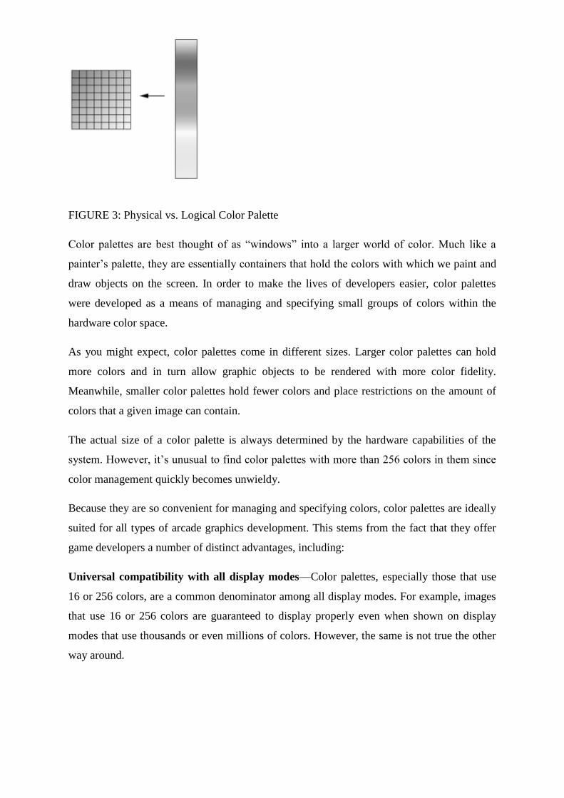
FIGURE 3: Physical vs. Logical Color Palette
Color palettes are best thought of as ―windows‖ into a larger world of color. Much like a
painter‘s palette, they are essentially containers that hold the colors with which we paint and
draw objects on the screen. In order to make the lives of developers easier, color palettes
were developed as a means of managing and specifying small groups of colors within the
hardware color space.
As you might expect, color palettes come in different sizes. Larger color palettes can hold
more colors and in turn allow graphic objects to be rendered with more color fidelity.
Meanwhile, smaller color palettes hold fewer colors and place restrictions on the amount of
colors that a given image can contain.
The actual size of a color palette is always determined by the hardware capabilities of the
system. However, it‘s unusual to find color palettes with more than 256 colors in them since
color management quickly becomes unwieldy.
Because they are so convenient for managing and specifying colors, color palettes are ideally
suited for all types of arcade graphics development. This stems from the fact that they offer
game developers a number of distinct advantages, including:
Universal compatibility with all display modes—Color palettes, especially those that use
16 or 256 colors, are a common denominator among all display modes. For example, images
that use 16 or 256 colors are guaranteed to display properly even when shown on display
modes that use thousands or even millions of colors. However, the same is not true the other
way around.
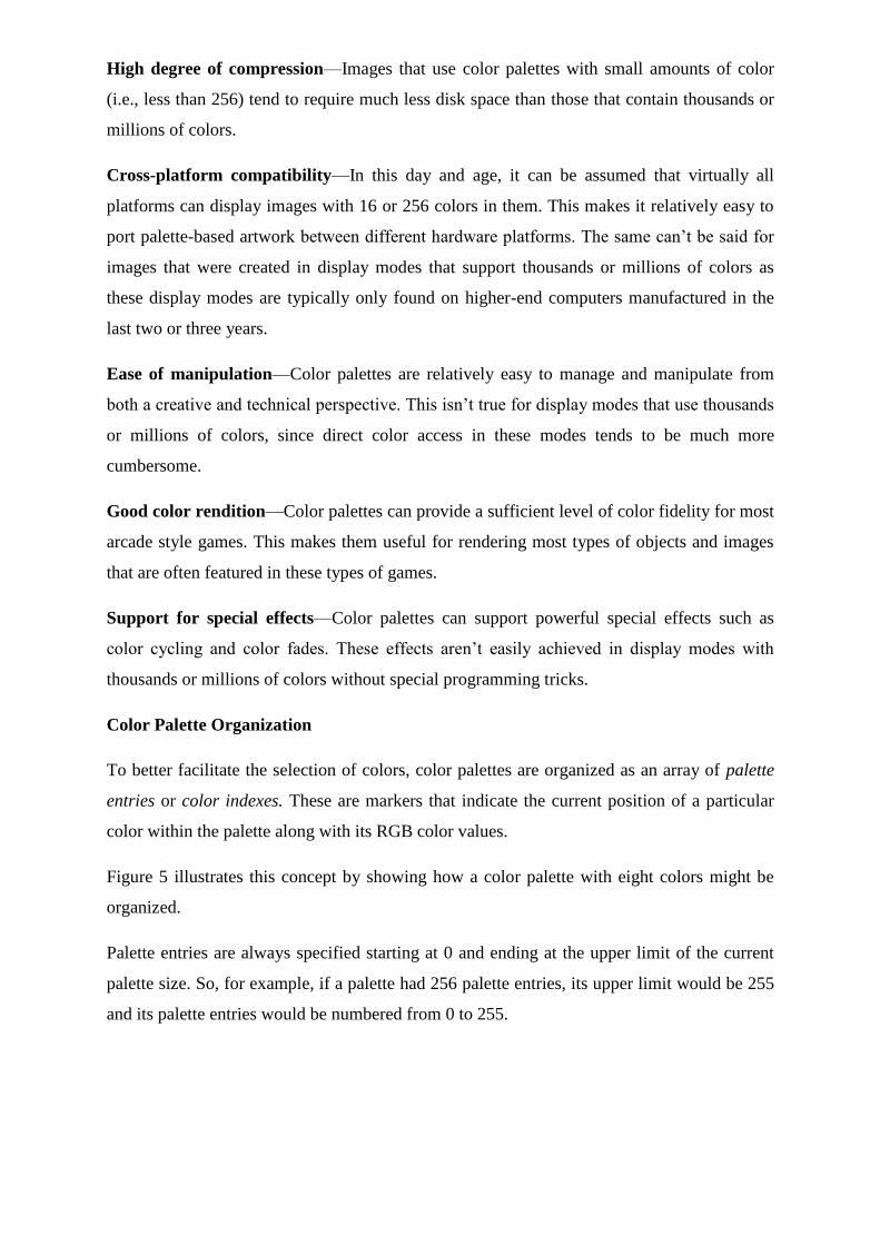
High degree of compression—Images that use color palettes with small amounts of color
(i.e., less than 256) tend to require much less disk space than those that contain thousands or
millions of colors.
Cross-platform compatibility—In this day and age, it can be assumed that virtually all
platforms can display images with 16 or 256 colors in them. This makes it relatively easy to
port palette-based artwork between different hardware platforms. The same can‘t be said for
images that were created in display modes that support thousands or millions of colors as
these display modes are typically only found on higher-end computers manufactured in the
last two or three years.
Ease of manipulation—Color palettes are relatively easy to manage and manipulate from
both a creative and technical perspective. This isn‘t true for display modes that use thousands
or millions of colors, since direct color access in these modes tends to be much more
cumbersome.
Good color rendition—Color palettes can provide a sufficient level of color fidelity for most
arcade style games. This makes them useful for rendering most types of objects and images
that are often featured in these types of games.
Support for special effects—Color palettes can support powerful special effects such as
color cycling and color fades. These effects aren‘t easily achieved in display modes with
thousands or millions of colors without special programming tricks.
Color Palette Organization
To better facilitate the selection of colors, color palettes are organized as an array of palette
entries or color indexes. These are markers that indicate the current position of a particular
color within the palette along with its RGB color values.
Figure 5 illustrates this concept by showing how a color palette with eight colors might be
organized.
Palette entries are always specified starting at 0 and ending at the upper limit of the current
palette size. So, for example, if a palette had 256 palette entries, its upper limit would be 255
and its palette entries would be numbered from 0 to 255.
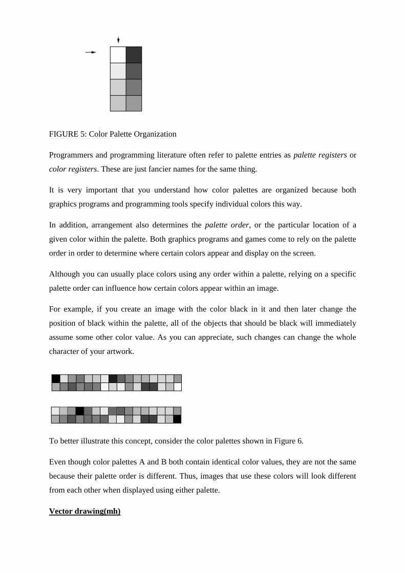
FIGURE 5: Color Palette Organization
Programmers and programming literature often refer to palette entries as palette registers or
color registers. These are just fancier names for the same thing.
It is very important that you understand how color palettes are organized because both
graphics programs and programming tools specify individual colors this way.
In addition, arrangement also determines the palette order, or the particular location of a
given color within the palette. Both graphics programs and games come to rely on the palette
order in order to determine where certain colors appear and display on the screen.
Although you can usually place colors using any order within a palette, relying on a specific
palette order can influence how certain colors appear within an image.
For example, if you create an image with the color black in it and then later change the
position of black within the palette, all of the objects that should be black will immediately
assume some other color value. As you can appreciate, such changes can change the whole
character of your artwork.
To better illustrate this concept, consider the color palettes shown in Figure 6.
Even though color palettes A and B both contain identical color values, they are not the same
because their palette order is different. Thus, images that use these colors will look different
from each other when displayed using either palette.
Vector drawing(mh)
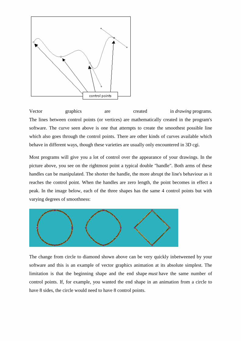
Vector graphics are created in drawing programs.
The lines between control points (or vertices) are mathematically created in the program's
software. The curve seen above is one that attempts to create the smoothest possible line
which also goes through the control points. There are other kinds of curves available which
behave in different ways, though these varieties are usually only encountered in 3D cgi.
Most programs will give you a lot of control over the appearance of your drawings. In the
picture above, you see on the rightmost point a typical double "handle". Both arms of these
handles can be manipulated. The shorter the handle, the more abrupt the line's behaviour as it
reaches the control point. When the handles are zero length, the point becomes in effect a
peak. In the image below, each of the three shapes has the same 4 control points but with
varying degrees of smoothness:
The change from circle to diamond shown above can be very quickly inbetweened by your
software and this is an example of vector graphics animation at its absolute simplest. The
limitation is that the beginning shape and the end shape must have the same number of
control points. If, for example, you wanted the end shape in an animation from a circle to
have 8 sides, the circle would need to have 8 control points.
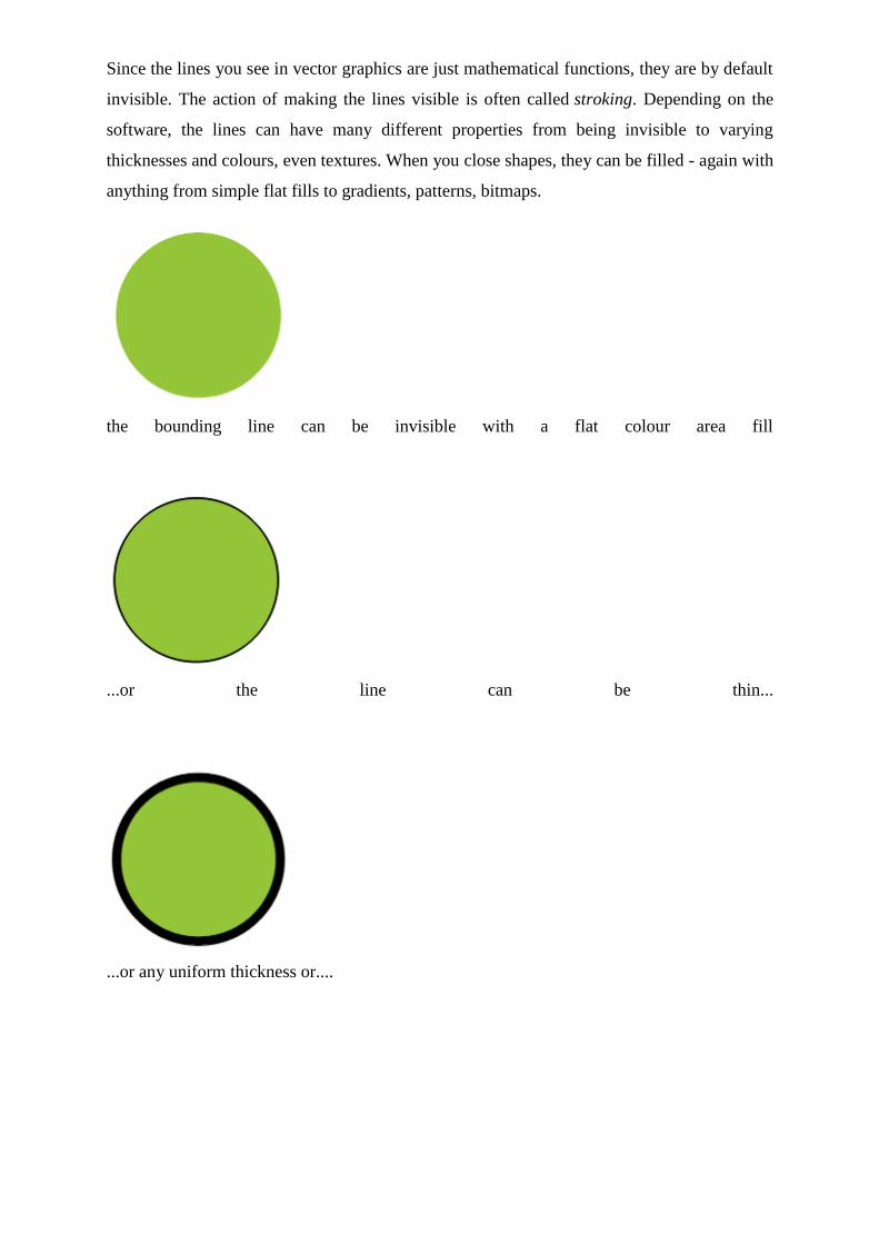
Since the lines you see in vector graphics are just mathematical functions, they are by default
invisible. The action of making the lines visible is often called stroking. Depending on the
software, the lines can have many different properties from being invisible to varying
thicknesses and colours, even textures. When you close shapes, they can be filled - again with
anything from simple flat fills to gradients, patterns, bitmaps.
the bounding line can be invisible with a flat colour area fill
...or the line can be thin...
...or any uniform thickness or....
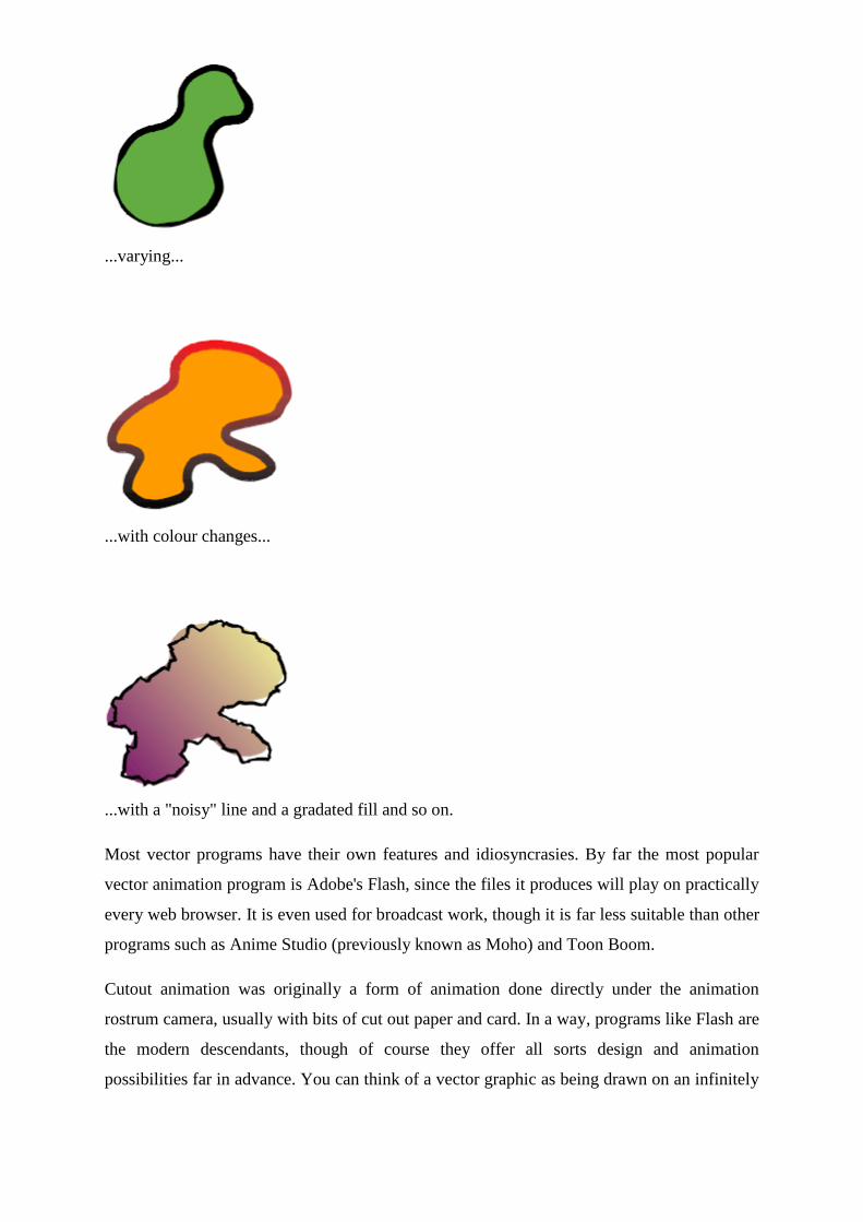
...varying...
...with colour changes...
...with a "noisy" line and a gradated fill and so on.
Most vector programs have their own features and idiosyncrasies. By far the most popular
vector animation program is Adobe's Flash, since the files it produces will play on practically
every web browser. It is even used for broadcast work, though it is far less suitable than other
programs such as Anime Studio (previously known as Moho) and Toon Boom.
Cutout animation was originally a form of animation done directly under the animation
rostrum camera, usually with bits of cut out paper and card. In a way, programs like Flash are
the modern descendants, though of course they offer all sorts design and animation
possibilities far in advance. You can think of a vector graphic as being drawn on an infinitely
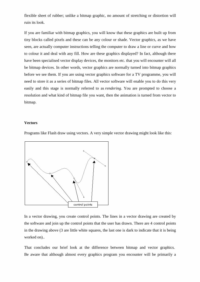
flexible sheet of rubber; unlike a bitmap graphic, no amount of stretching or distortion will
ruin its look.
If you are familiar with bitmap graphics, you will know that these graphics are built up from
tiny blocks called pixels and these can be any colour or shade. Vector graphics, as we have
seen, are actually computer instructions telling the computer to draw a line or curve and how
to colour it and deal with any fill. How are these graphics displayed? In fact, although there
have been specialised vector display devices, the monitors etc. that you will encounter will all
be bitmap devices. In other words, vector graphics are normally turned into bitmap graphics
before we see them. If you are using vector graphics software for a TV programme, you will
need to store it as a series of bitmap files. All vector software will enable you to do this very
easily and this stage is normally referred to as rendering. You are prompted to choose a
resolution and what kind of bitmap file you want, then the animation is turned from vector to
bitmap.
Vectors
Programs like Flash draw using vectors. A very simple vector drawing might look like this:
In a vector drawing, you create control points. The lines in a vector drawing are created by
the software and join up the control points that the user has drawn. There are 4 control points
in the drawing above (3 are little white squares, the last one is dark to indicate that it is being
worked on)..
That concludes our brief look at the difference between bitmap and vector graphics.
Be aware that although almost every graphics program you encounter will be primarily a
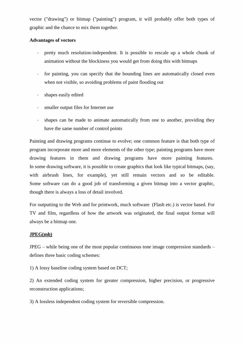
vector ("drawing") or bitmap ("painting") program, it will probably offer both types of
graphic and the chance to mix them together.
Advantages of vectors
pretty much resolution-independent. It is possible to rescale up a whole chunk of
animation without the blockiness you would get from doing this with bitmaps
for painting, you can specify that the bounding lines are automatically closed even
when not visible, so avoiding problems of paint flooding out
shapes easily edited
smaller output files for Internet use
shapes can be made to animate automatically from one to another, providing they
have the same number of control points
Painting and drawing programs continue to evolve; one common feature is that both type of
program incorporate more and more elements of the other type; painting programs have more
drawing features in them and drawing programs have more painting features.
In some drawing software, it is possible to create graphics that look like typical bitmaps, (say,
with airbrush lines, for example), yet still remain vectors and so be editable.
Some software can do a good job of transforming a given bitmap into a vector graphic,
though there is always a loss of detail involved.
For outputting to the Web and for printwork, much software (Flash etc.) is vector based. For
TV and film, regardless of how the artwork was originated, the final output format will
always be a bitmap one.
JPEG(mh)
JPEG – while being one of the most popular continuous tone image compression standards –
defines three basic coding schemes:
1) A lossy baseline coding system based on DCT;
2) An extended coding system for greater compression, higher precision, or progressive
reconstruction applications;
3) A lossless independent coding system for reversible compression.
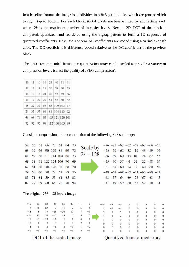
In a baseline format, the image is subdivided into 8x8 pixel blocks, which are processed left
to right, top to bottom. For each block, its 64 pixels are level-shifted by subtracting 2k-1,
where 2k is the maximum number of intensity levels. Next, a 2D DCT of the block is
computed, quantized, and reordered using the zigzag pattern to form a 1D sequence of
quantized coefficients. Next, the nonzero AC coefficients are coded using a variable-length
code. The DC coefficient is difference coded relative to the DC coefficient of the previous
block.
The JPEG recommended luminance quantization array can be scaled to provide a variety of
compression levels (select the quality of JPEG compression).
Consider compression and reconstruction of the following 8x8 subimage:
The original 256 = 28 levels image
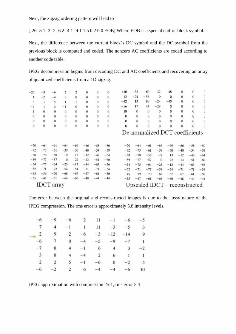
Next, the zigzag ordering pattern will lead to
[-26 -3 1 -3 -2 -6 2 -4 1 -4 1 1 5 0 2 0 0 EOB] Where EOB is a special end-of-block symbol.
Next, the difference between the current block‘s DC symbol and the DC symbol from the
previous block is computed and coded. The nonzero AC coefficients are coded according to
another code table.
JPEG decompression begins from decoding DC and AC coefficients and recovering an array
of quantized coefficients from a 1D zigzag.
The error between the original and reconstructed images is due to the lossy nature of the
JPEG compression. The rms error is approximately 5.8 intensity levels.
JPEG approximation with compression 25:1, rms error 5.4
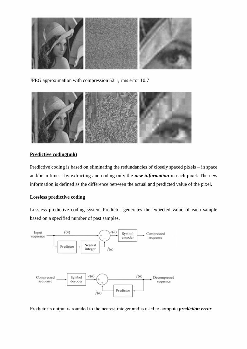
JPEG approximation with compression 52:1, rms error 10.7
Predictive coding(mh)
Predictive coding is based on eliminating the redundancies of closely spaced pixels – in space
and/or in time – by extracting and coding only the new information in each pixel. The new
information is defined as the difference between the actual and predicted value of the pixel.
Lossless predictive coding
Lossless predictive coding system Predictor generates the expected value of each sample
based on a specified number of past samples.
Predictor‘s output is rounded to the nearest integer and is used to compute prediction error
e(n) = f (n) −fˆ(n)
Prediction error is encoded by a variable-length code to generate the next element of the
encoded data stream. The decoder reconstructs e(n) from the encoded data and performs the
inverse operation
f (n) = e(n) + fˆ(n)
Various local global and adaptive methods can be used to generate f ˆ (n) local, global, Often,
the prediction is a linear combination of m previous samples:
Where m is the order of the linear predictor and αi, i = 1,…m are prediction coefficients,
f(n) are the input pixels. The m samples used for prediction can be taken from the current
scan line (1D linear predictive coding – LPC), from the current and previous line (2D LPC),
or from the current image and the previous images in an image sequence (3D LPC). The 1D
LPC:
which is a function of the previous pixels in the current line. Note that the prediction cannot
be formed for the first m pixels. These pixels are coded by other means (f.e. Huffman code).
For the image shown, form a first-order (m = 1) LPC in form
fˆ(x, y) = round [αf (x, y −1)]
A predictor is called a previous pixel predictor, and the coding procedure is differential
(previous pixel) coding.Prediction error image up-scaled by 128.
The average prediction error 0.26 The entropy reduction is due to removal of spatial
redundancy.
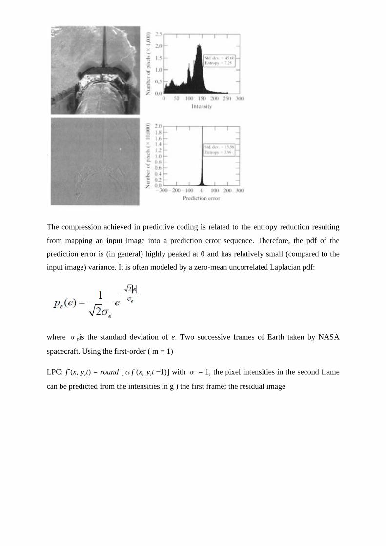
The compression achieved in predictive coding is related to the entropy reduction resulting
from mapping an input image into a prediction error sequence. Therefore, the pdf of the
prediction error is (in general) highly peaked at 0 and has relatively small (compared to the
input image) variance. It is often modeled by a zero-mean uncorrelated Laplacian pdf:
where σeis the standard deviation of e. Two successive frames of Earth taken by NASA
spacecraft. Using the first-order ( m = 1)
LPC: fˆ(x, y,t) = round [αf (x, y,t −1)] with α = 1, the pixel intensities in the second frame
can be predicted from the intensities in g ) the first frame; the residual image
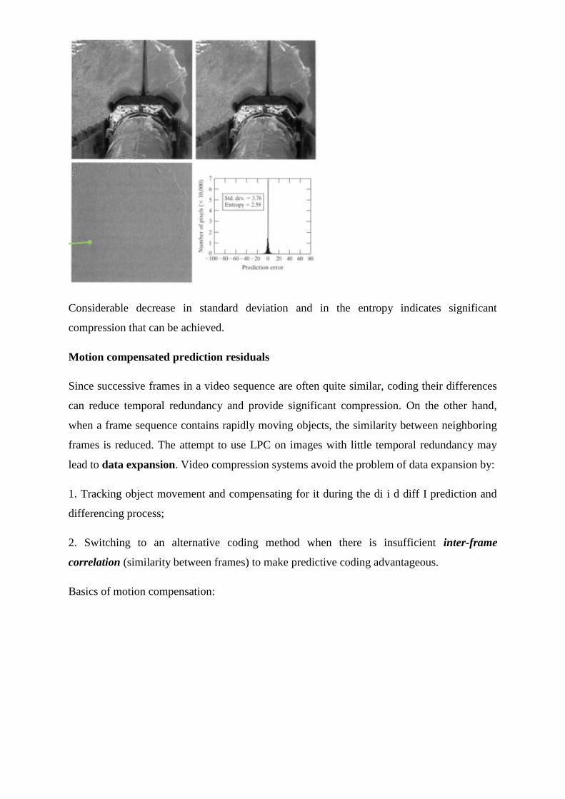
Considerable decrease in standard deviation and in the entropy indicates significant
compression that can be achieved.
Motion compensated prediction residuals
Since successive frames in a video sequence are often quite similar, coding their differences
can reduce temporal redundancy and provide significant compression. On the other hand,
when a frame sequence contains rapidly moving objects, the similarity between neighboring
frames is reduced. The attempt to use LPC on images with little temporal redundancy may
lead to data expansion. Video compression systems avoid the problem of data expansion by:
1. Tracking object movement and compensating for it during the di i d diff I prediction and
differencing process;
2. Switching to an alternative coding method when there is insufficient inter-frame
correlation (similarity between frames) to make predictive coding advantageous.
Basics of motion compensation:
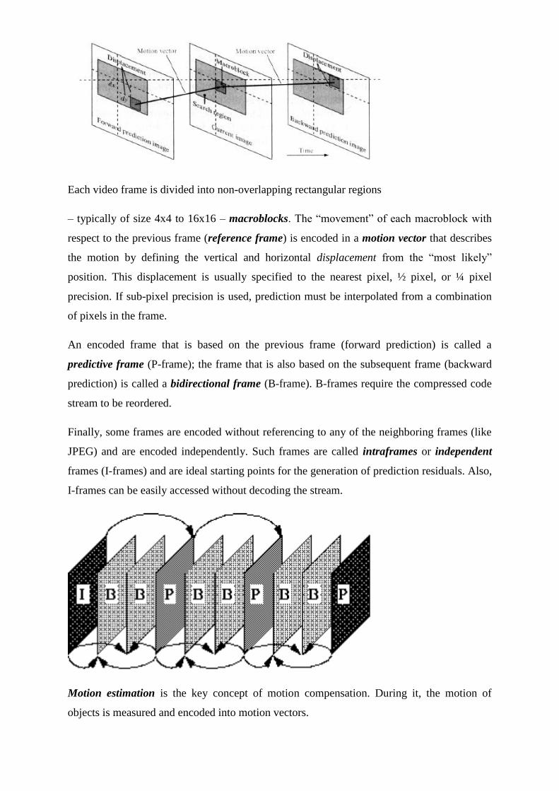
Each video frame is divided into non-overlapping rectangular regions
– typically of size 4x4 to 16x16 – macroblocks. The ―movement‖ of each macroblock with
respect to the previous frame (reference frame) is encoded in a motion vector that describes
the motion by defining the vertical and horizontal displacement from the ―most likely‖
position. This displacement is usually specified to the nearest pixel, ½ pixel, or ¼ pixel
precision. If sub-pixel precision is used, prediction must be interpolated from a combination
of pixels in the frame.
An encoded frame that is based on the previous frame (forward prediction) is called a
predictive frame (P-frame); the frame that is also based on the subsequent frame (backward
prediction) is called a bidirectional frame (B-frame). B-frames require the compressed code
stream to be reordered.
Finally, some frames are encoded without referencing to any of the neighboring frames (like
JPEG) and are encoded independently. Such frames are called intraframes or independent
frames (I-frames) and are ideal starting points for the generation of prediction residuals. Also,
I-frames can be easily accessed without decoding the stream.
Motion estimation is the key concept of motion compensation. During it, the motion of
objects is measured and encoded into motion vectors.
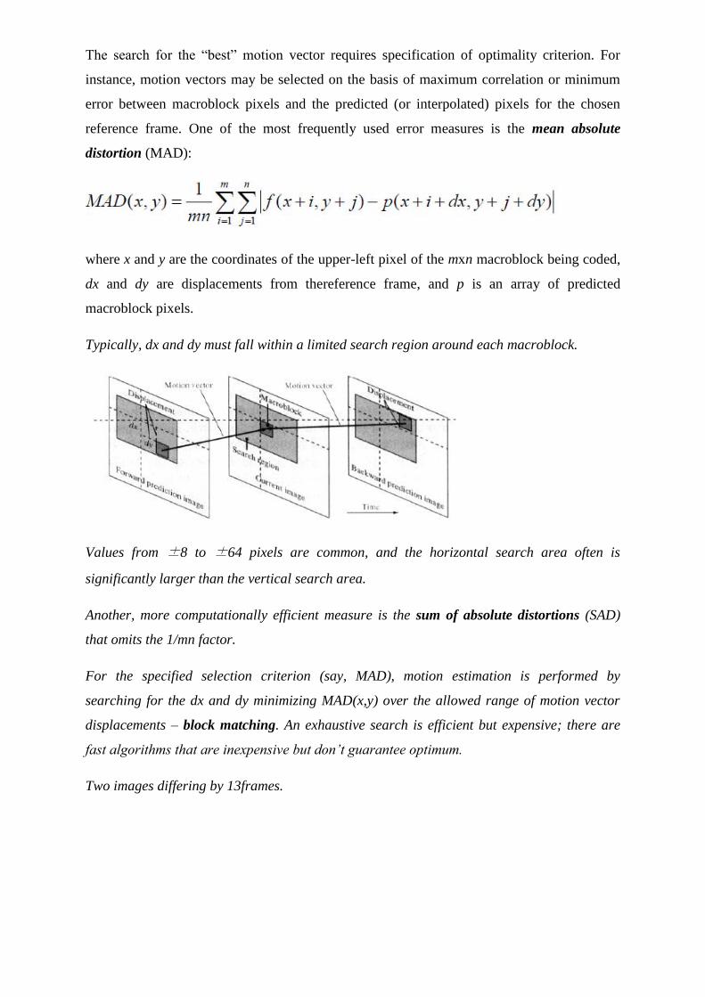
The search for the ―best‖ motion vector requires specification of optimality criterion. For
instance, motion vectors may be selected on the basis of maximum correlation or minimum
error between macroblock pixels and the predicted (or interpolated) pixels for the chosen
reference frame. One of the most frequently used error measures is the mean absolute
distortion (MAD):
where x and y are the coordinates of the upper-left pixel of the mxn macroblock being coded,
dx and dy are displacements from thereference frame, and p is an array of predicted
macroblock pixels.
Typically, dx and dy must fall within a limited search region around each macroblock.
Values from ±8 to ±64 pixels are common, and the horizontal search area often is
significantly larger than the vertical search area.
Another, more computationally efficient measure is the sum of absolute distortions (SAD)
that omits the 1/mn factor.
For the specified selection criterion (say, MAD), motion estimation is performed by
searching for the dx and dy minimizing MAD(x,y) over the allowed range of motion vector
displacements – block matching. An exhaustive search is efficient but expensive; there are
fast algorithms that are inexpensive but don’t guarantee optimum.
Two images differing by 13frames.
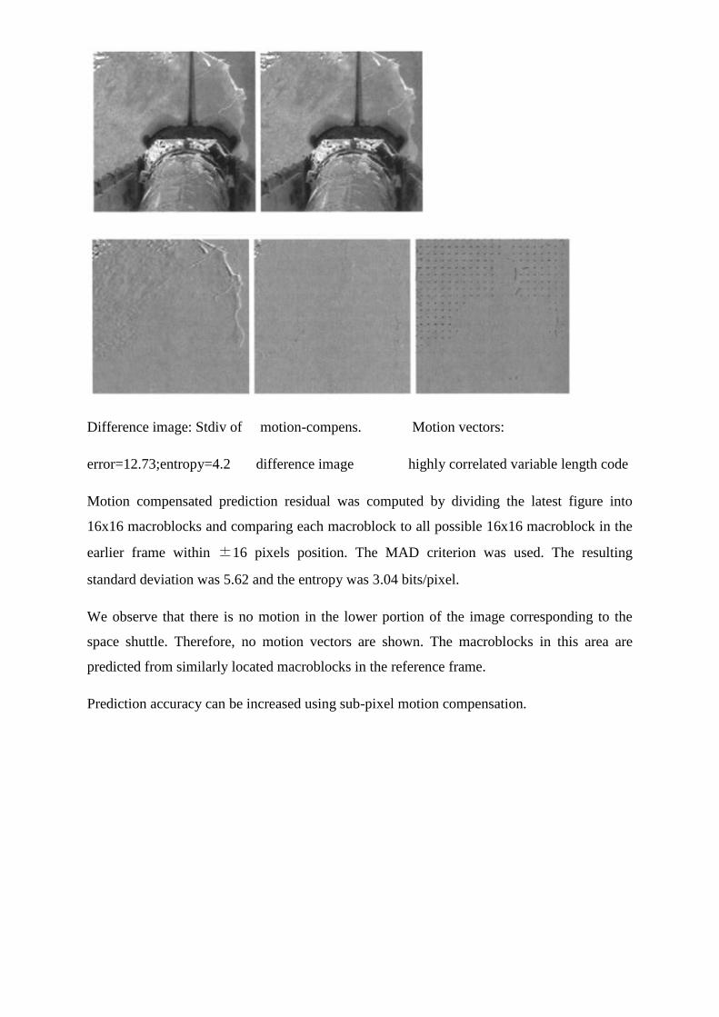
Difference image: Stdiv of motion-compens. Motion vectors:
error=12.73;entropy=4.2 difference image highly correlated variable length code
Motion compensated prediction residual was computed by dividing the latest figure into
16x16 macroblocks and comparing each macroblock to all possible 16x16 macroblock in the
earlier frame within ±16 pixels position. The MAD criterion was used. The resulting
standard deviation was 5.62 and the entropy was 3.04 bits/pixel.
We observe that there is no motion in the lower portion of the image corresponding to the
space shuttle. Therefore, no motion vectors are shown. The macroblocks in this area are
predicted from similarly located macroblocks in the reference frame.
Prediction accuracy can be increased using sub-pixel motion compensation.
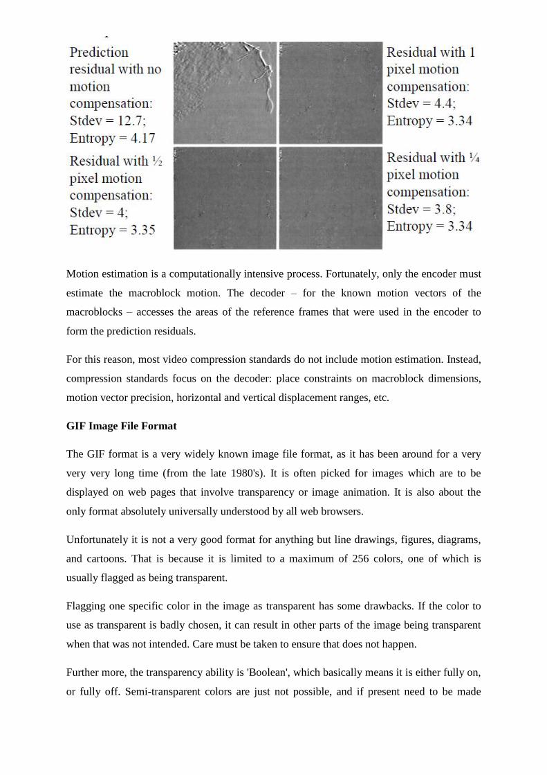
Motion estimation is a computationally intensive process. Fortunately, only the encoder must
estimate the macroblock motion. The decoder – for the known motion vectors of the
macroblocks – accesses the areas of the reference frames that were used in the encoder to
form the prediction residuals.
For this reason, most video compression standards do not include motion estimation. Instead,
compression standards focus on the decoder: place constraints on macroblock dimensions,
motion vector precision, horizontal and vertical displacement ranges, etc.
GIF Image File Format
The GIF format is a very widely known image file format, as it has been around for a very
very very long time (from the late 1980's). It is often picked for images which are to be
displayed on web pages that involve transparency or image animation. It is also about the
only format absolutely universally understood by all web browsers.
Unfortunately it is not a very good format for anything but line drawings, figures, diagrams,
and cartoons. That is because it is limited to a maximum of 256 colors, one of which is
usually flagged as being transparent.
Flagging one specific color in the image as transparent has some drawbacks. If the color to
use as transparent is badly chosen, it can result in other parts of the image being transparent
when that was not intended. Care must be taken to ensure that does not happen.
Further more, the transparency ability is 'Boolean', which basically means it is either fully on,
or fully off. Semi-transparent colors are just not possible, and if present need to be made
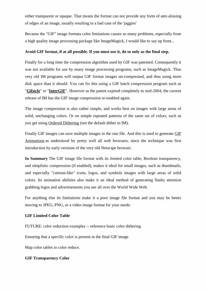
either transparent or opaque. That means the format can not provide any form of anti-aliasing
of edges of an image, usually resulting in a bad case of the 'jaggies'
Because the "GIF" image formats color limitations causes so many problems, especially from
a high quality image processing package like ImageMagick, I would like to say up front...
Avoid GIF format, if at all possible. If you must use it, do so only as the final step.
Finally for a long time the compression algorithm used by GIF was patented. Consequently it
was not available for use by many image processing programs, such as ImageMagick. Thus
very old IM programs will output GIF format images un-compressed, and thus using more
disk space than it should. You can fix this using a GIF batch compression program such as
"Gifsicle" or "InterGIF". However as the patent expired completely in mid-2004, the current
release of IM has the GIF image compression re-enabled again.
The image compression is also rather simple, and works best on images with large areas of
solid, unchanging colors. Or on simple repeated patterns of the same set of colors, such as
you get using Ordered Dithering (not the default dither in IM).
Finally GIF images can save multiple images in the one file. And this is used to generate GIF
Animations as understood by pretty well all web browsers, since the technique was first
introduction by early versions of the very old Netscape browser.
In Summary The GIF image file format with its limited color table, Boolean transparency,
and simplistic compression (if enabled), makes it ideal for small images, such as thumbnails,
and especially "cartoon-like" icons, logos, and symbols images with large areas of solid
colors. Its animation abilities also make it an ideal method of generating flashy attention
grabbing logos and advertisements you see all over the World Wide Web.
For anything else its limitations make it a poor image file format and you may be better
moving to JPEG, PNG, or a video image format for your needs.
GIF Limited Color Table
FUTURE: color reduction examples -- reference basic color dithering
Ensuring that a specific color is present in the final GIF image
Map color tables to color reduce.
GIF Transparency Color
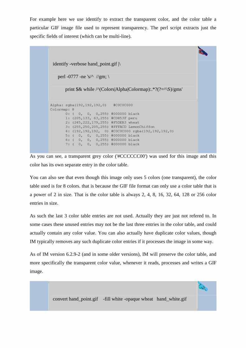
For example here we use identify to extract the transparent color, and the color table a
particular GIF image file used to represent transparency. The perl script extracts just the
specific fields of interest (which can be multi-line).
identify -verbose hand_point.gif |\
perl -0777 -ne 's/^ //gm; \
print $& while /^(Colors|Alpha|Colormap):.*?(?=^\S)/gms'
As you can see, a transparent grey color ('#CCCCCC00') was used for this image and this
color has its own separate entry in the color table.
You can also see that even though this image only uses 5 colors (one transparent), the color
table used is for 8 colors. that is because the GIF file format can only use a color table that is
a power of 2 in size. That is the color table is always 2, 4, 8, 16, 32, 64, 128 or 256 color
entries in size.
As such the last 3 color table entries are not used. Actually they are just not refered to. In
some cases these unused entries may not be the last three entries in the color table, and could
actually contain any color value. You can also actually have duplicate color values, though
IM typically removes any such duplicate color entries if it processes the image in some way.
As of IM version 6.2.9-2 (and in some older versions), IM will preserve the color table, and
more specifically the transparent color value, whenever it reads, processes and writes a GIF
image.
convert hand_point.gif -fill white -opaque wheat hand_white.gif
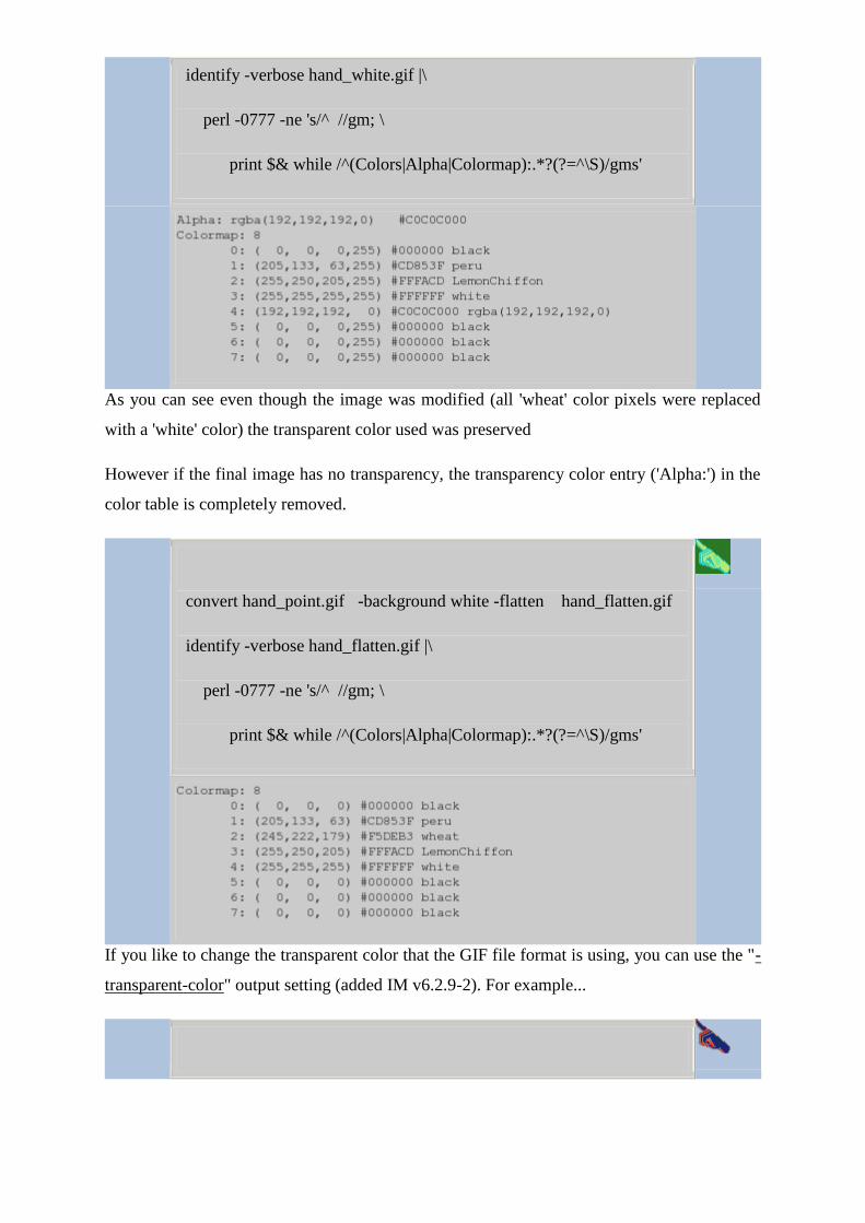
identify -verbose hand_white.gif |\
perl -0777 -ne 's/^ //gm; \
print $& while /^(Colors|Alpha|Colormap):.*?(?=^\S)/gms'
As you can see even though the image was modified (all 'wheat' color pixels were replaced
with a 'white' color) the transparent color used was preserved
However if the final image has no transparency, the transparency color entry ('Alpha:') in the
color table is completely removed.
convert hand_point.gif -background white -flatten hand_flatten.gif
identify -verbose hand_flatten.gif |\
perl -0777 -ne 's/^ //gm; \
print $& while /^(Colors|Alpha|Colormap):.*?(?=^\S)/gms'
If you like to change the transparent color that the GIF file format is using, you can use the "-
transparent-color" output setting (added IM v6.2.9-2). For example...
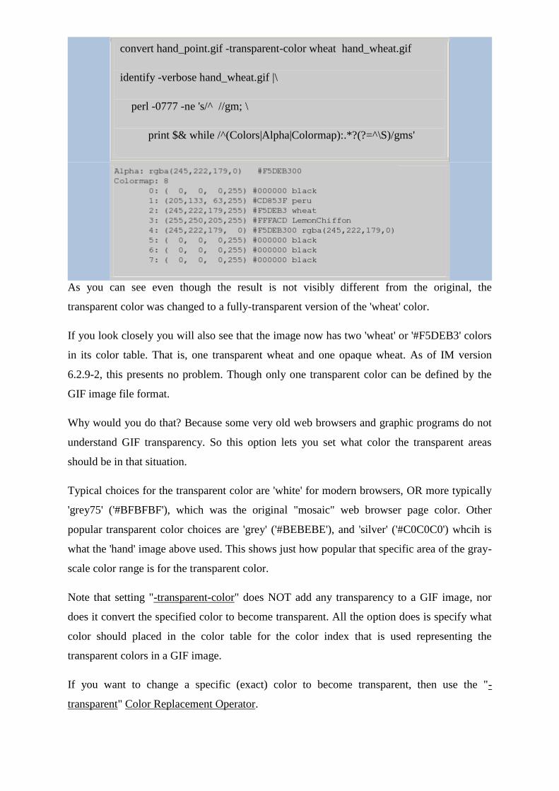
convert hand_point.gif -transparent-color wheat hand_wheat.gif
identify -verbose hand_wheat.gif |\
perl -0777 -ne 's/^ //gm; \
print $& while /^(Colors|Alpha|Colormap):.*?(?=^\S)/gms'
As you can see even though the result is not visibly different from the original, the
transparent color was changed to a fully-transparent version of the 'wheat' color.
If you look closely you will also see that the image now has two 'wheat' or '#F5DEB3' colors
in its color table. That is, one transparent wheat and one opaque wheat. As of IM version
6.2.9-2, this presents no problem. Though only one transparent color can be defined by the
GIF image file format.
Why would you do that? Because some very old web browsers and graphic programs do not
understand GIF transparency. So this option lets you set what color the transparent areas
should be in that situation.
Typical choices for the transparent color are 'white' for modern browsers, OR more typically
'grey75' ('#BFBFBF'), which was the original "mosaic" web browser page color. Other
popular transparent color choices are 'grey' ('#BEBEBE'), and 'silver' ('#C0C0C0') whcih is
what the 'hand' image above used. This shows just how popular that specific area of the gray-
scale color range is for the transparent color.
Note that setting "-transparent-color" does NOT add any transparency to a GIF image, nor
does it convert the specified color to become transparent. All the option does is specify what
color should placed in the color table for the color index that is used representing the
transparent colors in a GIF image.
If you want to change a specific (exact) color to become transparent, then use the "-
transparent" Color Replacement Operator.
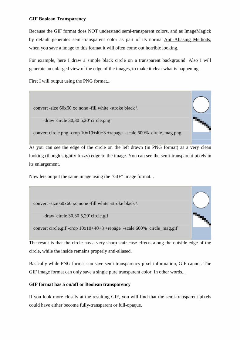
GIF Boolean Transparency
Because the GIF format does NOT understand semi-transparent colors, and as ImageMagick
by default generates semi-transparent color as part of its normal Anti-Aliasing Methods,
when you save a image to this format it will often come out horrible looking.
For example, here I draw a simple black circle on a transparent background. Also I will
generate an enlarged view of the edge of the images, to make it clear what is happening.
First I will output using the PNG format...
convert -size 60x60 xc:none -fill white -stroke black \
-draw 'circle 30,30 5,20' circle.png
convert circle.png -crop 10x10+40+3 +repage -scale 600% circle_mag.png
As you can see the edge of the circle on the left drawn (in PNG format) as a very clean
looking (though slightly fuzzy) edge to the image. You can see the semi-transparent pixels in
its enlargement.
Now lets output the same image using the "GIF" image format...
convert -size 60x60 xc:none -fill white -stroke black \
-draw 'circle 30,30 5,20' circle.gif
convert circle.gif -crop 10x10+40+3 +repage -scale 600% circle_mag.gif
The result is that the circle has a very sharp stair case effects along the outside edge of the
circle, while the inside remains properly anti-aliased.
Basically while PNG format can save semi-transparency pixel information, GIF cannot. The
GIF image format can only save a single pure transparent color. In other words...
GIF format has a on/off or Boolean transparency
If you look more closely at the resulting GIF, you will find that the semi-transparent pixels
could have either become fully-transparent or full-opaque.
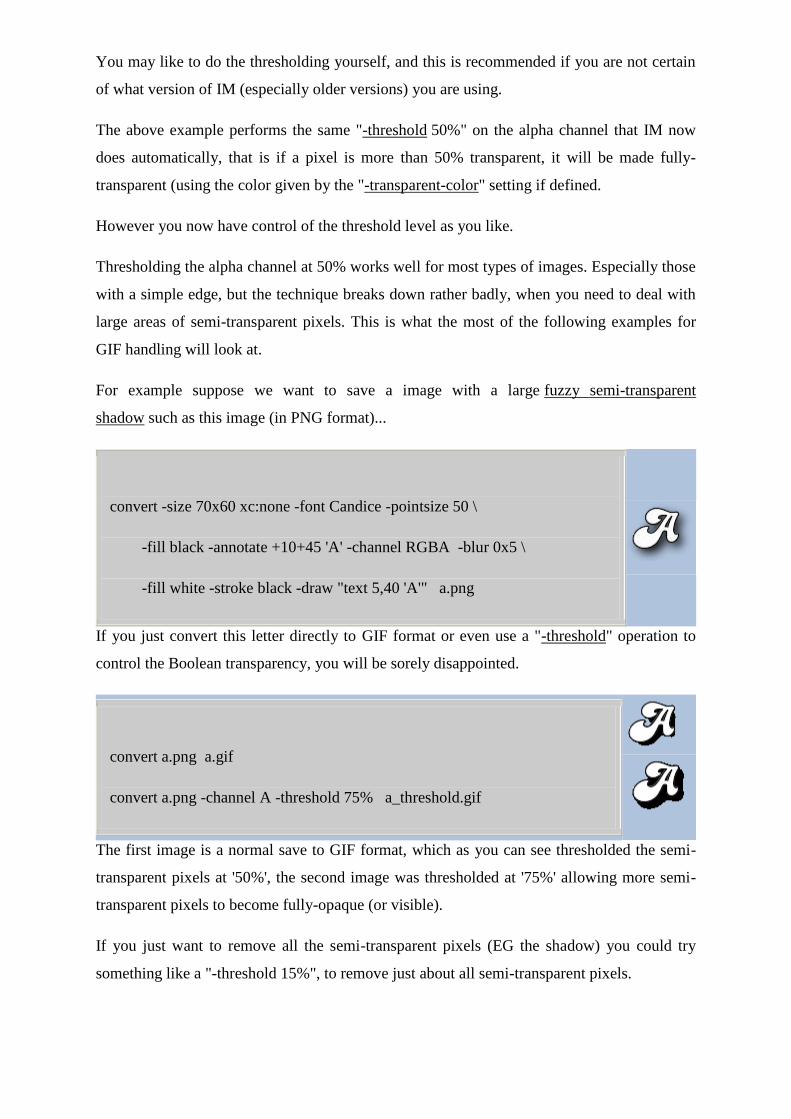
You may like to do the thresholding yourself, and this is recommended if you are not certain
of what version of IM (especially older versions) you are using.
The above example performs the same "-threshold 50%" on the alpha channel that IM now
does automatically, that is if a pixel is more than 50% transparent, it will be made fully-
transparent (using the color given by the "-transparent-color" setting if defined.
However you now have control of the threshold level as you like.
Thresholding the alpha channel at 50% works well for most types of images. Especially those
with a simple edge, but the technique breaks down rather badly, when you need to deal with
large areas of semi-transparent pixels. This is what the most of the following examples for
GIF handling will look at.
For example suppose we want to save a image with a large fuzzy semi-transparent
shadow such as this image (in PNG format)...
convert -size 70x60 xc:none -font Candice -pointsize 50 \
-fill black -annotate +10+45 'A' -channel RGBA -blur 0x5 \
-fill white -stroke black -draw "text 5,40 'A'" a.png
If you just convert this letter directly to GIF format or even use a "-threshold" operation to
control the Boolean transparency, you will be sorely disappointed.
convert a.png a.gif
convert a.png -channel A -threshold 75% a_threshold.gif
The first image is a normal save to GIF format, which as you can see thresholded the semi-
transparent pixels at '50%', the second image was thresholded at '75%' allowing more semi-
transparent pixels to become fully-opaque (or visible).
If you just want to remove all the semi-transparent pixels (EG the shadow) you could try
something like a "-threshold 15%", to remove just about all semi-transparent pixels.
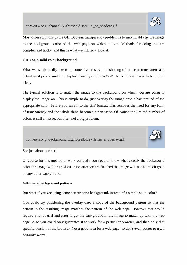
convert a.png -channel A -threshold 15% a_no_shadow.gif
Most other solutions to the GIF Boolean transparency problem is to inextricably tie the image
to the background color of the web page on which it lives. Methods for doing this are
complex and tricky, and this is what we will now look at.
GIFs on a solid color background
What we would really like to to somehow preserve the shading of the semi-transparent and
anti-aliased pixels, and still display it nicely on the WWW. To do this we have to be a little
tricky.
The typical solution is to match the image to the background on which you are going to
display the image on. This is simple to do, just overlay the image onto a background of the
appropriate color, before you save it to the GIF format. This removes the need for any form
of transparency and the whole thing becomes a non-issue. Of course the limited number of
colors is still an issue, but often not a big problem.
convert a.png -background LightSteelBlue -flatten a_overlay.gif
See just about perfect!
Of course for this method to work correctly you need to know what exactly the background
color the image will be used on. Also after we are finished the image will not be much good
on any other background.
GIFs on a background pattern
But what if you are using some pattern for a background, instead of a simple solid color?
You could try positioning the overlay onto a copy of the background pattern so that the
pattern in the resulting image matches the pattern of the web page. However that would
require a lot of trial and error to get the background in the image to match up with the web
page. Also you could only guarantee it to work for a particular browser, and then only that
specific version of the browser. Not a good idea for a web page, so don't even bother to try. I
certainly won't.
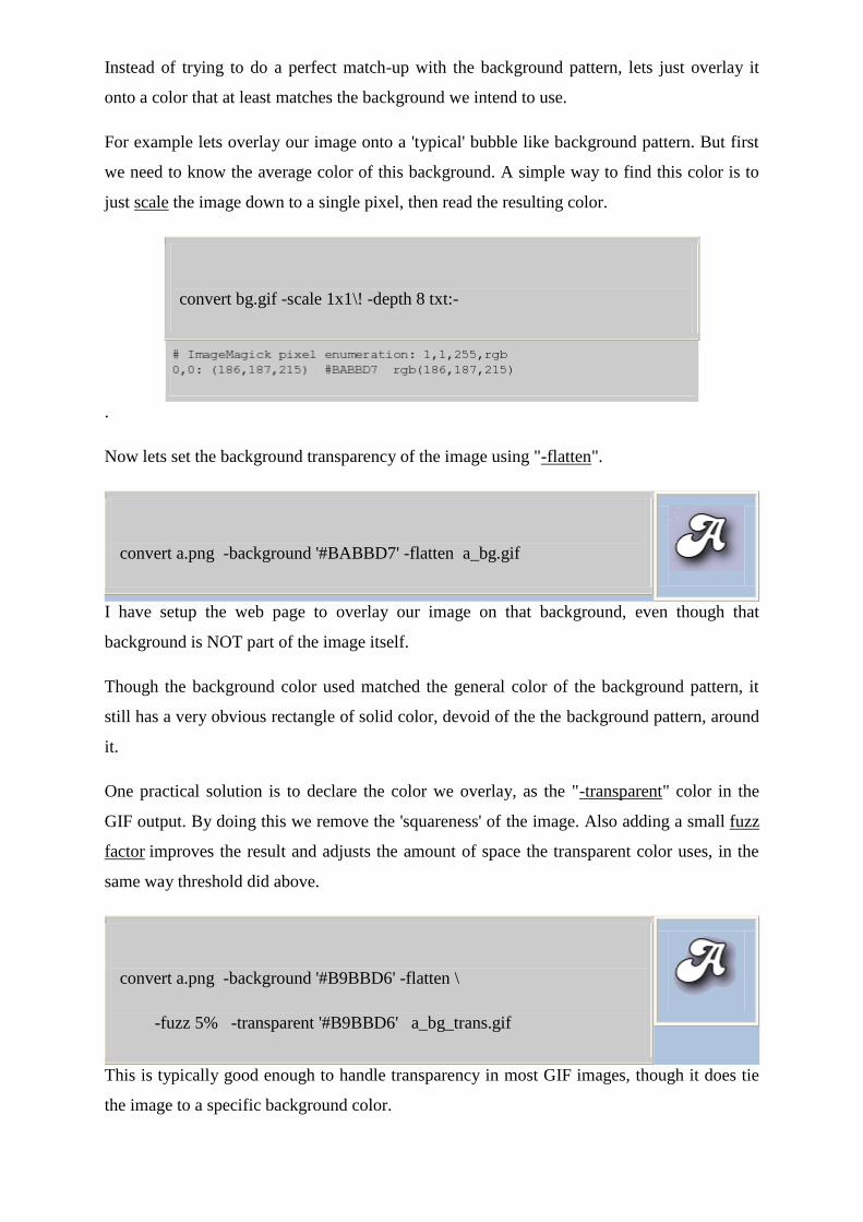
Instead of trying to do a perfect match-up with the background pattern, lets just overlay it
onto a color that at least matches the background we intend to use.
For example lets overlay our image onto a 'typical' bubble like background pattern. But first
we need to know the average color of this background. A simple way to find this color is to
just scale the image down to a single pixel, then read the resulting color.
convert bg.gif -scale 1x1\! -depth 8 txt:-
.
Now lets set the background transparency of the image using "-flatten".
convert a.png -background '#BABBD7' -flatten a_bg.gif
I have setup the web page to overlay our image on that background, even though that
background is NOT part of the image itself.
Though the background color used matched the general color of the background pattern, it
still has a very obvious rectangle of solid color, devoid of the the background pattern, around
it.
One practical solution is to declare the color we overlay, as the "-transparent" color in the
GIF output. By doing this we remove the 'squareness' of the image. Also adding a small fuzz
factor improves the result and adjusts the amount of space the transparent color uses, in the
same way threshold did above.
convert a.png -background '#B9BBD6' -flatten \
-fuzz 5% -transparent '#B9BBD6' a_bg_trans.gif
This is typically good enough to handle transparency in most GIF images, though it does tie
the image to a specific background color.
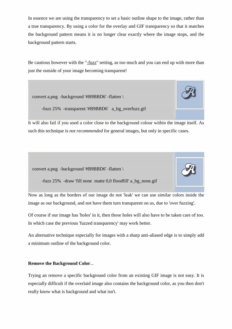
In essence we are using the transparency to set a basic outline shape to the image, rather than
a true transparency. By using a color for the overlay and GIF transparency so that it matches
the background pattern means it is no longer clear exactly where the image stops, and the
background pattern starts.
Be cautious however with the "-fuzz" setting, as too much and you can end up with more than
just the outside of your image becoming transparent!
convert a.png -background '#B9BBD6' -flatten \
-fuzz 25% -transparent '#B9BBD6' a_bg_overfuzz.gif
It will also fail if you used a color close to the background colour within the image itself. As
such this technique is not recommended for general images, but only in specific cases.
convert a.png -background '#B9BBD6' -flatten \
-fuzz 25% -draw 'fill none matte 0,0 floodfill' a_bg_none.gif
Now as long as the borders of our image do not 'leak' we can use similar colors inside the
image as our background, and not have them turn transparent on us, due to 'over fuzzing'.
Of course if our image has 'holes' in it, then those holes will also have to be taken care of too.
In which case the previous 'fuzzed transparency' may work better.
An alternative technique especially for images with a sharp anti-aliased edge is to simply add
a minimum outline of the background color.
Remove the Background Color...
Trying an remove a specific background color from an existing GIF image is not easy. It is
especially difficult if the overlaid image also contains the background color, as you then don't
really know what is background and what isn't.
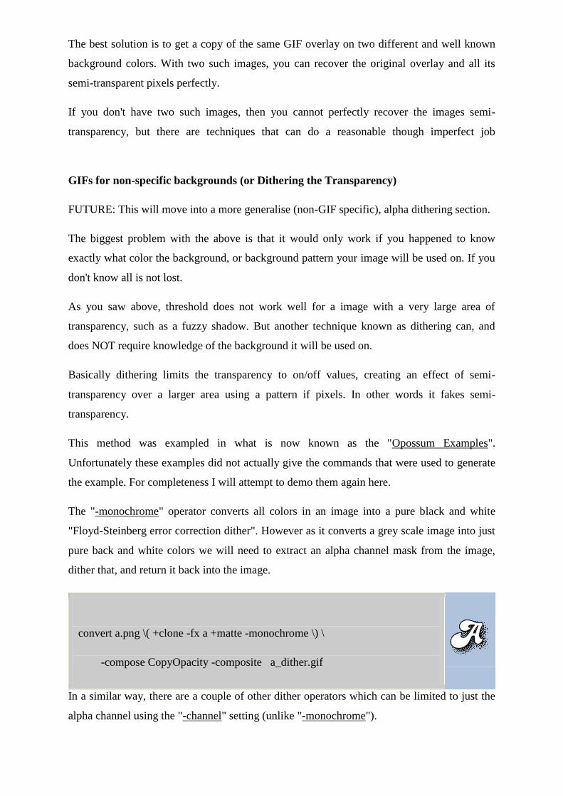
The best solution is to get a copy of the same GIF overlay on two different and well known
background colors. With two such images, you can recover the original overlay and all its
semi-transparent pixels perfectly.
If you don't have two such images, then you cannot perfectly recover the images semi-
transparency, but there are techniques that can do a reasonable though imperfect job
GIFs for non-specific backgrounds (or Dithering the Transparency)
FUTURE: This will move into a more generalise (non-GIF specific), alpha dithering section.
The biggest problem with the above is that it would only work if you happened to know
exactly what color the background, or background pattern your image will be used on. If you
don't know all is not lost.
As you saw above, threshold does not work well for a image with a very large area of
transparency, such as a fuzzy shadow. But another technique known as dithering can, and
does NOT require knowledge of the background it will be used on.
Basically dithering limits the transparency to on/off values, creating an effect of semi-
transparency over a larger area using a pattern if pixels. In other words it fakes semi-
transparency.
This method was exampled in what is now known as the "Opossum Examples".
Unfortunately these examples did not actually give the commands that were used to generate
the example. For completeness I will attempt to demo them again here.
The "-monochrome" operator converts all colors in an image into a pure black and white
"Floyd-Steinberg error correction dither". However as it converts a grey scale image into just
pure back and white colors we will need to extract an alpha channel mask from the image,
dither that, and return it back into the image.
convert a.png \( +clone -fx a +matte -monochrome \) \
-compose CopyOpacity -composite a_dither.gif
In a similar way, there are a couple of other dither operators which can be limited to just the
alpha channel using the "-channel" setting (unlike "-monochrome").
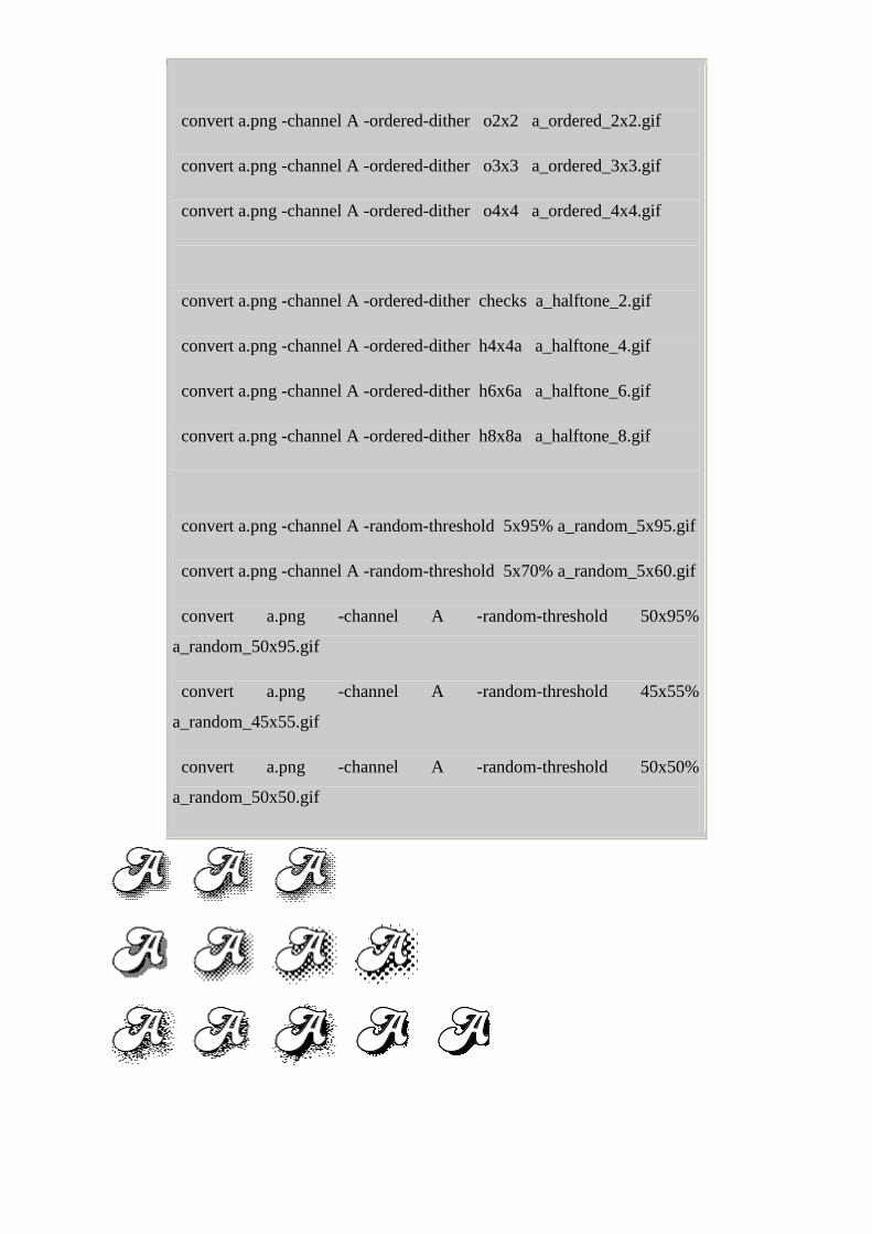
convert a.png -channel A -ordered-dither o2x2 a_ordered_2x2.gif
convert a.png -channel A -ordered-dither o3x3 a_ordered_3x3.gif
convert a.png -channel A -ordered-dither o4x4 a_ordered_4x4.gif
convert a.png -channel A -ordered-dither checks a_halftone_2.gif
convert a.png -channel A -ordered-dither h4x4a a_halftone_4.gif
convert a.png -channel A -ordered-dither h6x6a a_halftone_6.gif
convert a.png -channel A -ordered-dither h8x8a a_halftone_8.gif
convert a.png -channel A -random-threshold 5x95% a_random_5x95.gif
convert a.png -channel A -random-threshold 5x70% a_random_5x60.gif
convert a.png -channel A -random-threshold 50x95%
a_random_50x95.gif
convert a.png -channel A -random-threshold 45x55%
a_random_45x55.gif
convert a.png -channel A -random-threshold 50x50%
a_random_50x50.gif
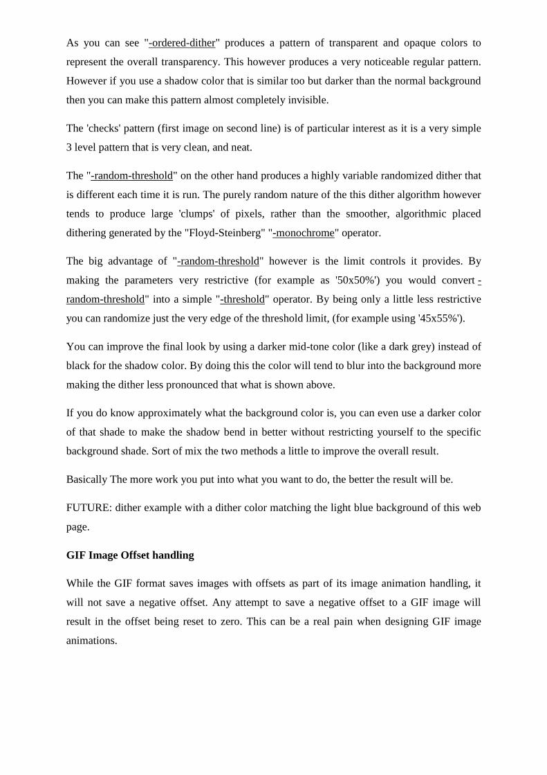
As you can see "-ordered-dither" produces a pattern of transparent and opaque colors to
represent the overall transparency. This however produces a very noticeable regular pattern.
However if you use a shadow color that is similar too but darker than the normal background
then you can make this pattern almost completely invisible.
The 'checks' pattern (first image on second line) is of particular interest as it is a very simple
3 level pattern that is very clean, and neat.
The "-random-threshold" on the other hand produces a highly variable randomized dither that
is different each time it is run. The purely random nature of the this dither algorithm however
tends to produce large 'clumps' of pixels, rather than the smoother, algorithmic placed
dithering generated by the "Floyd-Steinberg" "-monochrome" operator.
The big advantage of "-random-threshold" however is the limit controls it provides. By
making the parameters very restrictive (for example as '50x50%') you would convert -
random-threshold" into a simple "-threshold" operator. By being only a little less restrictive
you can randomize just the very edge of the threshold limit, (for example using '45x55%').
You can improve the final look by using a darker mid-tone color (like a dark grey) instead of
black for the shadow color. By doing this the color will tend to blur into the background more
making the dither less pronounced that what is shown above.
If you do know approximately what the background color is, you can even use a darker color
of that shade to make the shadow bend in better without restricting yourself to the specific
background shade. Sort of mix the two methods a little to improve the overall result.
Basically The more work you put into what you want to do, the better the result will be.
FUTURE: dither example with a dither color matching the light blue background of this web
page.
GIF Image Offset handling
While the GIF format saves images with offsets as part of its image animation handling, it
will not save a negative offset. Any attempt to save a negative offset to a GIF image will
result in the offset being reset to zero. This can be a real pain when designing GIF image
animations.
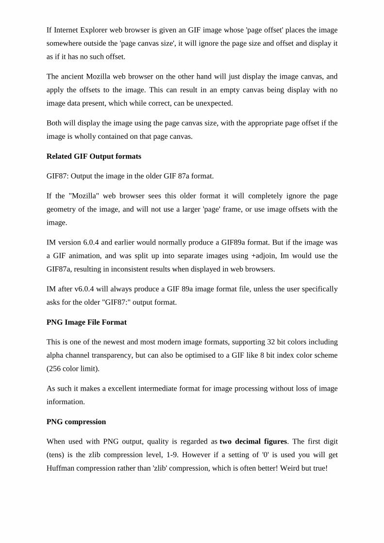
If Internet Explorer web browser is given an GIF image whose 'page offset' places the image
somewhere outside the 'page canvas size', it will ignore the page size and offset and display it
as if it has no such offset.
The ancient Mozilla web browser on the other hand will just display the image canvas, and
apply the offsets to the image. This can result in an empty canvas being display with no
image data present, which while correct, can be unexpected.
Both will display the image using the page canvas size, with the appropriate page offset if the
image is wholly contained on that page canvas.
Related GIF Output formats
GIF87: Output the image in the older GIF 87a format.
If the "Mozilla" web browser sees this older format it will completely ignore the page
geometry of the image, and will not use a larger 'page' frame, or use image offsets with the
image.
IM version 6.0.4 and earlier would normally produce a GIF89a format. But if the image was
a GIF animation, and was split up into separate images using +adjoin, Im would use the
GIF87a, resulting in inconsistent results when displayed in web browsers.
IM after v6.0.4 will always produce a GIF 89a image format file, unless the user specifically
asks for the older "GIF87:" output format.
PNG Image File Format
This is one of the newest and most modern image formats, supporting 32 bit colors including
alpha channel transparency, but can also be optimised to a GIF like 8 bit index color scheme
(256 color limit).
As such it makes a excellent intermediate format for image processing without loss of image
information.
PNG compression
When used with PNG output, quality is regarded as two decimal figures. The first digit
(tens) is the zlib compression level, 1-9. However if a setting of '0' is used you will get
Huffman compression rather than 'zlib' compression, which is often better! Weird but true!
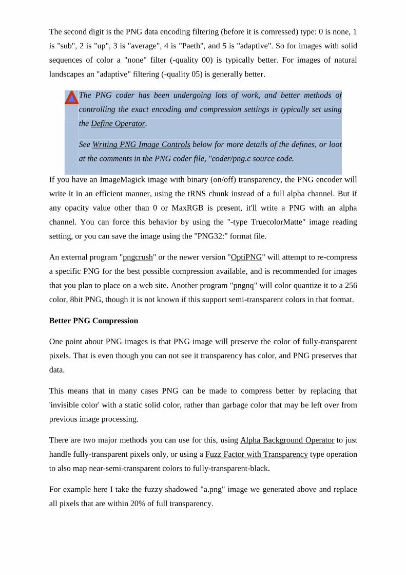
The second digit is the PNG data encoding filtering (before it is comressed) type: 0 is none, 1
is "sub", 2 is "up", 3 is "average", 4 is "Paeth", and 5 is "adaptive". So for images with solid
sequences of color a "none" filter (-quality 00) is typically better. For images of natural
landscapes an "adaptive" filtering (-quality 05) is generally better.
The PNG coder has been undergoing lots of work, and better methods of
controlling the exact encoding and compression settings is typically set using
the Define Operator.
See Writing PNG Image Controls below for more details of the defines, or loot
at the comments in the PNG coder file, "coder/png.c source code.
If you have an ImageMagick image with binary (on/off) transparency, the PNG encoder will
write it in an efficient manner, using the tRNS chunk instead of a full alpha channel. But if
any opacity value other than 0 or MaxRGB is present, it'll write a PNG with an alpha
channel. You can force this behavior by using the "-type TruecolorMatte" image reading
setting, or you can save the image using the "PNG32:" format file.
An external program "pngcrush" or the newer version "OptiPNG" will attempt to re-compress
a specific PNG for the best possible compression available, and is recommended for images
that you plan to place on a web site. Another program "pngnq" will color quantize it to a 256
color, 8bit PNG, though it is not known if this support semi-transparent colors in that format.
Better PNG Compression
One point about PNG images is that PNG image will preserve the color of fully-transparent
pixels. That is even though you can not see it transparency has color, and PNG preserves that
data.
This means that in many cases PNG can be made to compress better by replacing that
'invisible color' with a static solid color, rather than garbage color that may be left over from
previous image processing.
There are two major methods you can use for this, using Alpha Background Operator to just
handle fully-transparent pixels only, or using a Fuzz Factor with Transparency type operation
to also map near-semi-transparent colors to fully-transparent-black.
For example here I take the fuzzy shadowed "a.png" image we generated above and replace
all pixels that are within 20% of full transparency.
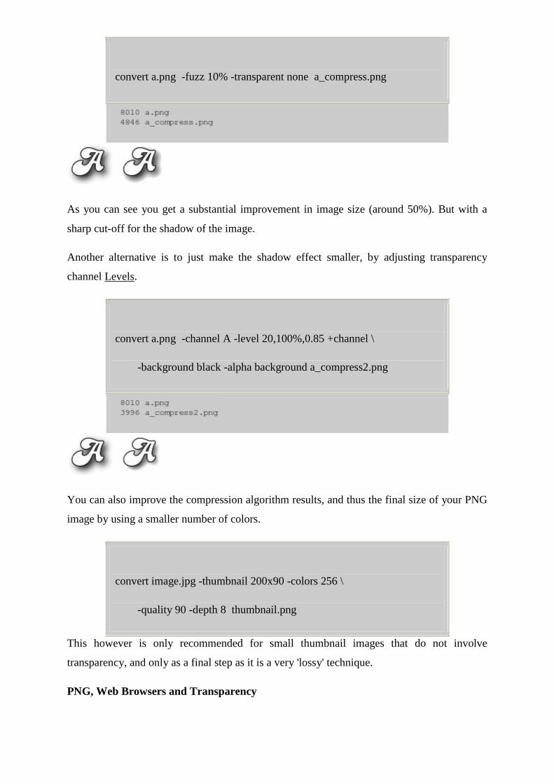
convert a.png -fuzz 10% -transparent none a_compress.png
As you can see you get a substantial improvement in image size (around 50%). But with a
sharp cut-off for the shadow of the image.
Another alternative is to just make the shadow effect smaller, by adjusting transparency
channel Levels.
convert a.png -channel A -level 20,100%,0.85 +channel \
-background black -alpha background a_compress2.png
You can also improve the compression algorithm results, and thus the final size of your PNG
image by using a smaller number of colors.
convert image.jpg -thumbnail 200x90 -colors 256 \
-quality 90 -depth 8 thumbnail.png
This however is only recommended for small thumbnail images that do not involve
transparency, and only as a final step as it is a very 'lossy' technique.
PNG, Web Browsers and Transparency
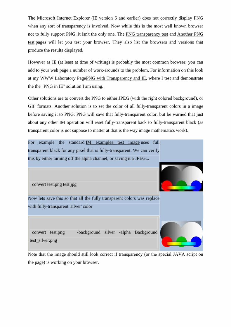
The Microsoft Internet Explorer (IE version 6 and earlier) does not correctly display PNG
when any sort of transparency is involved. Now while this is the most well known browser
not to fully support PNG, it isn't the only one. The PNG transparency test and Another PNG
test pages will let you test your browser. They also list the browsers and versions that
produce the results displayed.
However as IE (at least at time of writing) is probably the most common browser, you can
add to your web page a number of work-arounds to the problem. For information on this look
at my WWW Laboratory PagePNG with Transparency and IE, where I test and demonstrate
the the "PNG in IE" solution I am using.
Other solutions are to convert the PNG to either JPEG (with the right colored background), or
GIF formats. Another solution is to set the color of all fully-transparent colors in a image
before saving it to PNG. PNG will save that fully-transparent color, but be warned that just
about any other IM operation will reset fully-transparent back to fully-transparent black (as
transparent color is not suppose to matter at that is the way image mathematics work).
For example the standard IM examples test image uses full
transparent black for any pixel that is fully-transparent. We can verify
this by either turning off the alpha channel, or saving it a JPEG...
convert test.png test.jpg
Now lets save this so that all the fully transparent colors was replace
with fully-transparent 'silver' color
convert test.png -background silver -alpha Background
test_silver.png
Note that the image should still look correct if transparency (or the special JAVA script on
the page) is working on your browser.

But if we turn off the alpha channel (by saving to JPEG that does not
allow alpha) we can see that the PNG image really does use a 'silver'
color for the fully-transparent pixels.
convert test_silver.png test_silver.jpg
Note however that this does NOT modify semi-transparent pixels, and these will still have
their normal (non-transparent) colors without mixing that color with either the page
background, or the color used for fully-transparency.
As semi-transparency is no longer involved, borders can look jagged (aliased), as well as
'halo' effects, along lighter colored edges. For example look at the edges of the black and
white circles which show the 'jaggies' aliasing effects. However using a gray replacement
color should make this not as bad as as the original 'black' color used for full transparency.
The other advantage of setting the color of fully-transparent pixels, is a improvment in
compression of data. Sometimes, the underlying colors in transparent areas used during
processing were preserved. These in turn do not compress as well as a solid color. As such
setting the fully-transparent color as we did above, can produce a good saving in the final file
size.
However this should be done as a final step as many IM image processing operations will
replace any fully-transparent color that is present in an image back into fully-transparent
black. See the Alpha Background operator for a list of operators known to do this.
My preference is for PNG display problems, is for Microsoft to fix IE, and it seems that IE
version 7 will finally have a fully working PNG transparency handling, in all situations.
PNG and the Virtual Canvas
While normally PNG will NOT save virtual canvas size information, it does save virtual
canvas offset information, and if present, IM will try to generate a 'canvas size' that is
appropriate for that offset and image size. This can be important to remember for some image
operators such as "-crop", "-trim" and "-flatten", etc., which make use of the images canvas or
page size as part of its operation or results.
Of course you can use the "-page" setting and "-repage" operator, to set or remove the virtual
canvas size and offset. For example, the second IM "convert" sees the offset that is present in
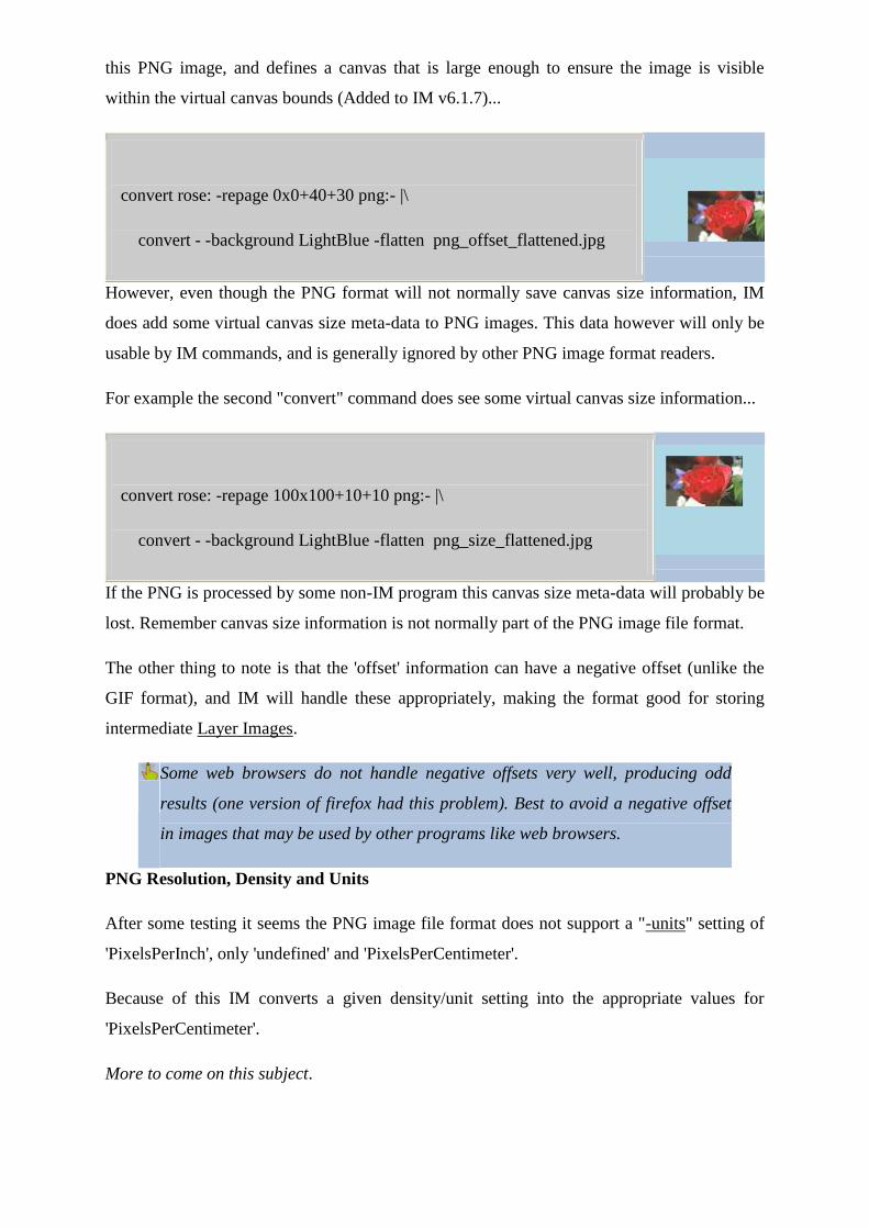
this PNG image, and defines a canvas that is large enough to ensure the image is visible
within the virtual canvas bounds (Added to IM v6.1.7)...
convert rose: -repage 0x0+40+30 png:- |\
convert - -background LightBlue -flatten png_offset_flattened.jpg
However, even though the PNG format will not normally save canvas size information, IM
does add some virtual canvas size meta-data to PNG images. This data however will only be
usable by IM commands, and is generally ignored by other PNG image format readers.
For example the second "convert" command does see some virtual canvas size information...
convert rose: -repage 100x100+10+10 png:- |\
convert - -background LightBlue -flatten png_size_flattened.jpg
If the PNG is processed by some non-IM program this canvas size meta-data will probably be
lost. Remember canvas size information is not normally part of the PNG image file format.
The other thing to note is that the 'offset' information can have a negative offset (unlike the
GIF format), and IM will handle these appropriately, making the format good for storing
intermediate Layer Images.
Some web browsers do not handle negative offsets very well, producing odd
results (one version of firefox had this problem). Best to avoid a negative offset
in images that may be used by other programs like web browsers.
PNG Resolution, Density and Units
After some testing it seems the PNG image file format does not support a "-units" setting of
'PixelsPerInch', only 'undefined' and 'PixelsPerCentimeter'.
Because of this IM converts a given density/unit setting into the appropriate values for
'PixelsPerCentimeter'.
More to come on this subject.
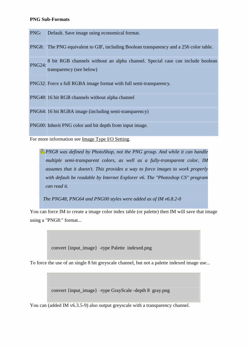
PNG Sub-Formats
PNG: Default. Save image using economical format.
PNG8: The PNG equivalent to GIF, including Boolean transparency and a 256 color table.
PNG24: 8 bit RGB channels without an alpha channel. Special case can include boolean
transparency (see below)
PNG32: Force a full RGBA image format with full semi-transparency.
PNG48: 16 bit RGB channels without alpha channel
PNG64: 16 bit RGBA image (including semi-transparency)
PNG00: Inherit PNG color and bit depth from input image.
For more information see Image Type I/O Setting.
PNG8 was defined by PhotoShop, not the PNG group. And while it can handle
multiple semi-transparent colors, as well as a fully-transparent color, IM
assumes that it doesn't. This provides a way to force images to work properly
with default be readable by Internet Explorer v6. The "Photoshop CS" program
can read it.
The PNG48, PNG64 and PNG00 styles were added as of IM v6.8.2-0
You can force IM to create a image color index table (or palette) then IM will save that image
using a "PNG8:" format...
convert {input_image} -type Palette indexed.png
To force the use of an single 8 bit greyscale channel, but not a palette indexed image use...
convert {input_image} -type GrayScale -depth 8 gray.png
You can (added IM v6.3.5-9) also output greyscale with a transparency channel.
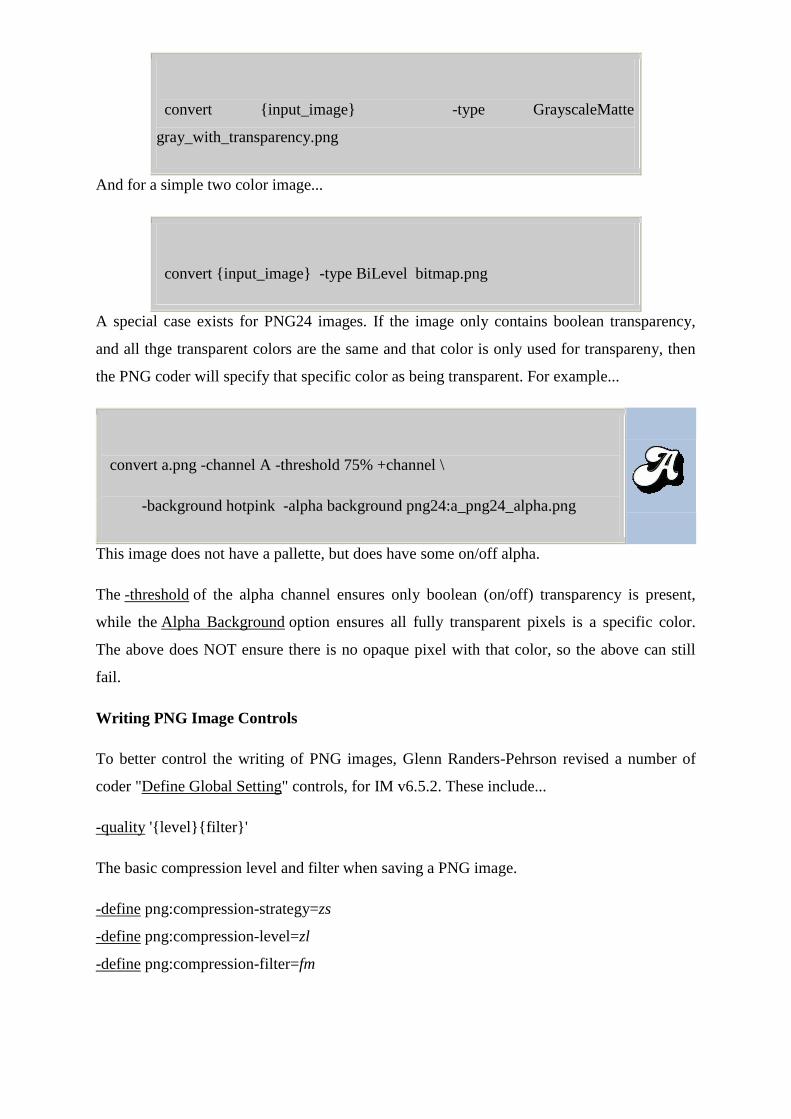
convert {input_image} -type GrayscaleMatte
gray_with_transparency.png
And for a simple two color image...
convert {input_image} -type BiLevel bitmap.png
A special case exists for PNG24 images. If the image only contains boolean transparency,
and all thge transparent colors are the same and that color is only used for transpareny, then
the PNG coder will specify that specific color as being transparent. For example...
convert a.png -channel A -threshold 75% +channel \
-background hotpink -alpha background png24:a_png24_alpha.png
This image does not have a pallette, but does have some on/off alpha.
The -threshold of the alpha channel ensures only boolean (on/off) transparency is present,
while the Alpha Background option ensures all fully transparent pixels is a specific color.
The above does NOT ensure there is no opaque pixel with that color, so the above can still
fail.
Writing PNG Image Controls
To better control the writing of PNG images, Glenn Randers-Pehrson revised a number of
coder "Define Global Setting" controls, for IM v6.5.2. These include...
-quality '{level}{filter}'
The basic compression level and filter when saving a PNG image.
-define png:compression-strategy=zs
-define png:compression-level=zl
-define png:compression-filter=fm
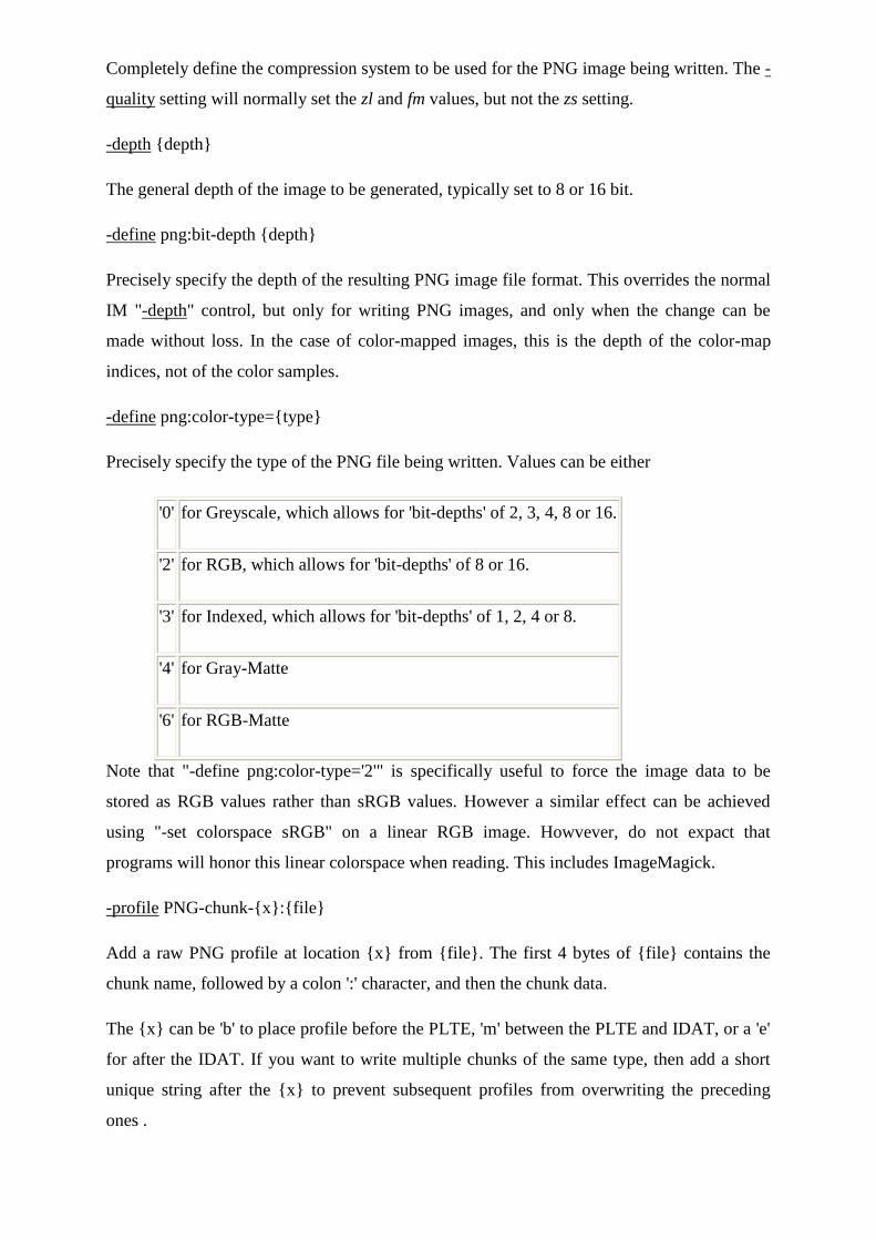
Completely define the compression system to be used for the PNG image being written. The -
quality setting will normally set the zl and fm values, but not the zs setting.
-depth {depth}
The general depth of the image to be generated, typically set to 8 or 16 bit.
-define png:bit-depth {depth}
Precisely specify the depth of the resulting PNG image file format. This overrides the normal
IM "-depth" control, but only for writing PNG images, and only when the change can be
made without loss. In the case of color-mapped images, this is the depth of the color-map
indices, not of the color samples.
-define png:color-type={type}
Precisely specify the type of the PNG file being written. Values can be either
'0' for Greyscale, which allows for 'bit-depths' of 2, 3, 4, 8 or 16.
'2' for RGB, which allows for 'bit-depths' of 8 or 16.
'3' for Indexed, which allows for 'bit-depths' of 1, 2, 4 or 8.
'4' for Gray-Matte
'6' for RGB-Matte
Note that "-define png:color-type='2'" is specifically useful to force the image data to be
stored as RGB values rather than sRGB values. However a similar effect can be achieved
using "-set colorspace sRGB" on a linear RGB image. Howvever, do not expact that
programs will honor this linear colorspace when reading. This includes ImageMagick.
-profile PNG-chunk-{x}:{file}
Add a raw PNG profile at location {x} from {file}. The first 4 bytes of {file} contains the
chunk name, followed by a colon ':' character, and then the chunk data.
The {x} can be 'b' to place profile before the PLTE, 'm' between the PLTE and IDAT, or a 'e'
for after the IDAT. If you want to write multiple chunks of the same type, then add a short
unique string after the {x} to prevent subsequent profiles from overwriting the preceding
ones .
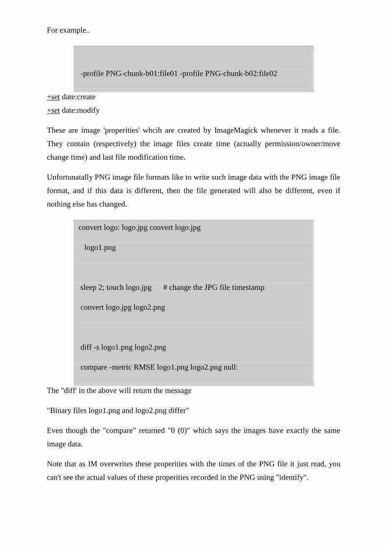
For example..
-profile PNG-chunk-b01:file01 -profile PNG-chunk-b02:file02
+set date:create
+set date:modify
These are image 'properities' whcih are created by ImageMagick whenever it reads a file.
They contain (respectively) the image files create time (actually permission/owner/move
change time) and last file modification time.
Unfortunatally PNG image file formats like to write such image data with the PNG image file
format, and if this data is different, then the file generated will also be different, even if
nothing else has changed.
convert logo: logo.jpg convert logo.jpg
logo1.png
sleep 2; touch logo.jpg # change the JPG file timestamp
convert logo.jpg logo2.png
diff -s logo1.png logo2.png
compare -metric RMSE logo1.png logo2.png null:
The "diff' in the above will return the message
"Binary files logo1.png and logo2.png differ"
Even though the "compare" returned "0 (0)" which says the images have exactly the same
image data.
Note that as IM overwrites these properities with the times of the PNG file it just read, you
can't see the actual values of these properities recorded in the PNG using "identify".
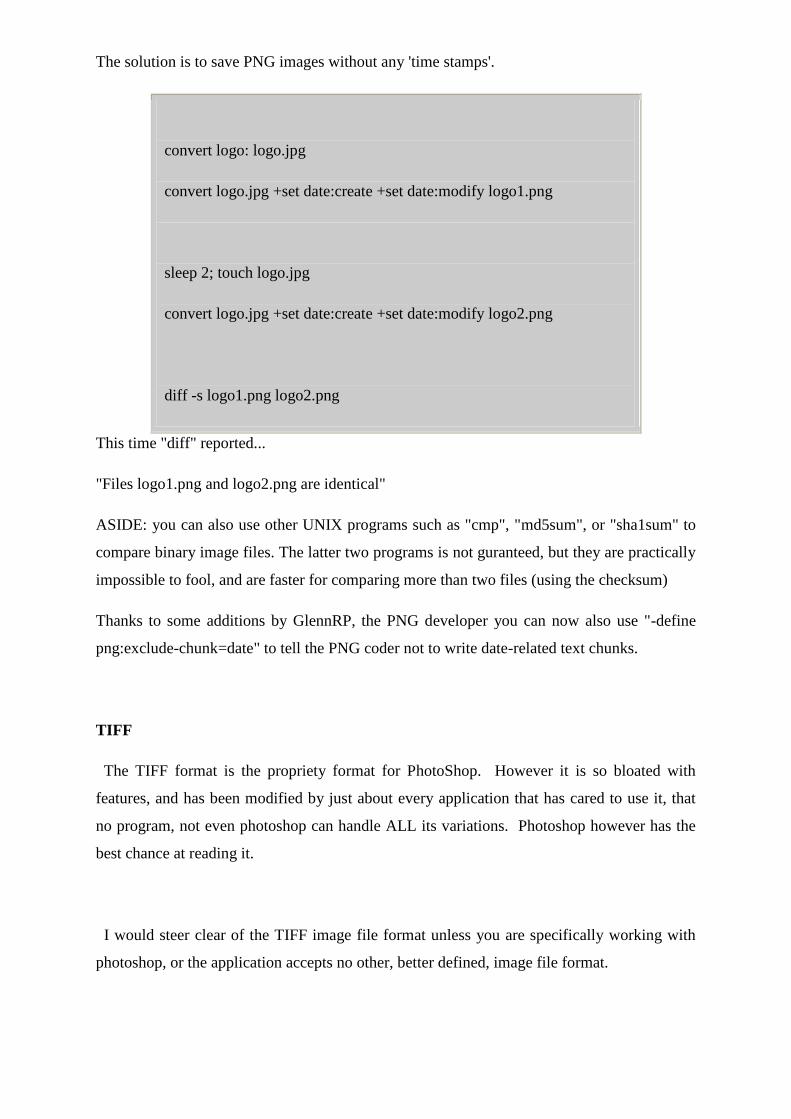
The solution is to save PNG images without any 'time stamps'.
convert logo: logo.jpg
convert logo.jpg +set date:create +set date:modify logo1.png
sleep 2; touch logo.jpg
convert logo.jpg +set date:create +set date:modify logo2.png
diff -s logo1.png logo2.png
This time "diff" reported...
"Files logo1.png and logo2.png are identical"
ASIDE: you can also use other UNIX programs such as "cmp", "md5sum", or "sha1sum" to
compare binary image files. The latter two programs is not guranteed, but they are practically
impossible to fool, and are faster for comparing more than two files (using the checksum)
Thanks to some additions by GlennRP, the PNG developer you can now also use "-define
png:exclude-chunk=date" to tell the PNG coder not to write date-related text chunks.
TIFF
The TIFF format is the propriety format for PhotoShop. However it is so bloated with
features, and has been modified by just about every application that has cared to use it, that
no program, not even photoshop can handle ALL its variations. Photoshop however has the
best chance at reading it.
I would steer clear of the TIFF image file format unless you are specifically working with
photoshop, or the application accepts no other, better defined, image file format.
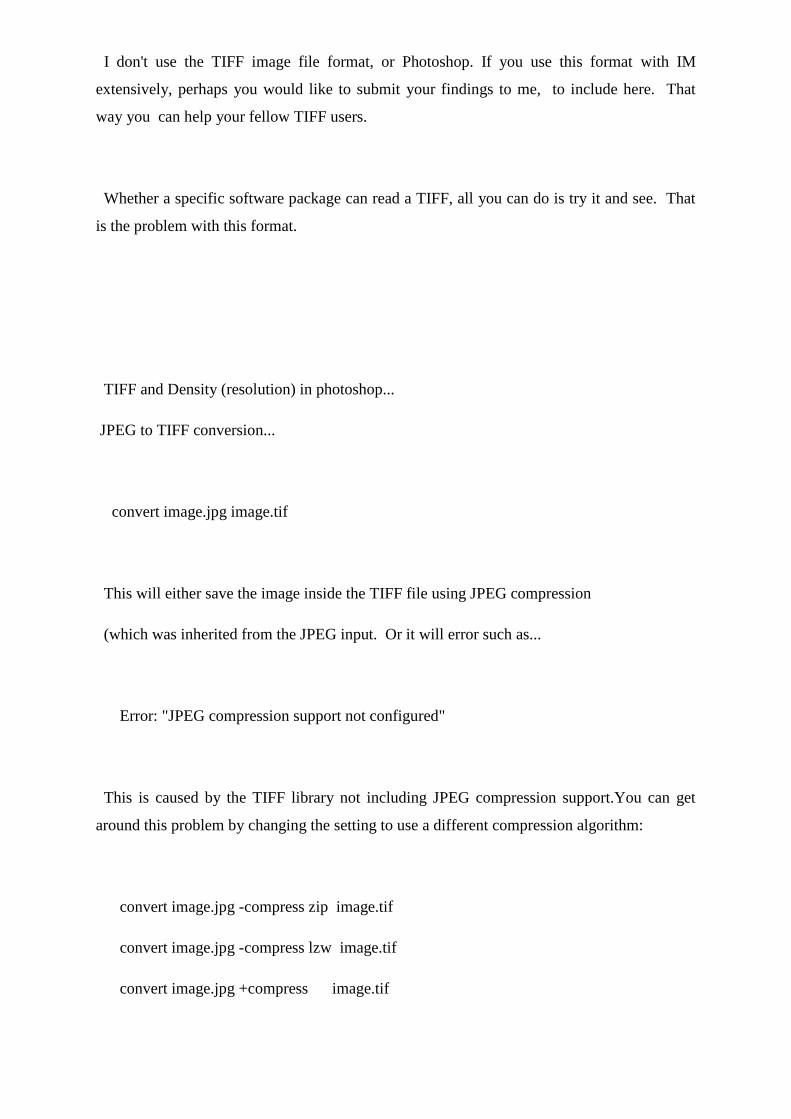
I don't use the TIFF image file format, or Photoshop. If you use this format with IM
extensively, perhaps you would like to submit your findings to me, to include here. That
way you can help your fellow TIFF users.
Whether a specific software package can read a TIFF, all you can do is try it and see. That
is the problem with this format.
TIFF and Density (resolution) in photoshop...
JPEG to TIFF conversion...
convert image.jpg image.tif
This will either save the image inside the TIFF file using JPEG compression
(which was inherited from the JPEG input. Or it will error such as...
Error: "JPEG compression support not configured"
This is caused by the TIFF library not including JPEG compression support.You can get
around this problem by changing the setting to use a different compression algorithm:
convert image.jpg -compress zip image.tif
convert image.jpg -compress lzw image.tif
convert image.jpg +compress image.tif
WARNING: -compress Group4 with a TIFF works, but ONLY if you remove all
transparent and semi-transparent pixels from the image. Typically you can make sure this is
done the same way as JPEG images above, using -background {color} -alpha remove just
before the final save (the first only works for single images).
TIFF (and MIFF) floating point precision files (Add to IM v6.2.6-5)...
This is especially good for HDRI image processing (which uses floating point
inside IM itself)
For single precision (float) set...
-depth 32 -define quantum:format=floating-point
For do8uble precision (doubles) set...
-depth 64 -define quantum:format=floating-point
14 bit TIFF images...
convert logo: -sharpen 0x1 -depth 14 logo.tif
tiffinfo logo.tif
Image Width: 640 Image Length: 480
Resolution: 72, 72 (unitless)
Bits/Sample: 14
Compression Scheme: LZW
Photometric Interpretation: RGB color
FillOrder: msb-to-lsb
Orientation: row 0 top, col 0 lhs
Samples/Pixel: 3
Rows/Strip: 2
Planar Configuration: single image plane
DocumentName: logo.tif
Software: ImageMagick 6.2.8 07/27/06 Q16 http://www.imagemagick.org
12 bit TIFF images...
To convert 16-bit TIFF images to 12-bit:
convert image.tif -depth 12 image-12.tif
Pure black and white images...
convert image ... -type truecolor -type bilevel image.tiff
Results in normal images and the smallest filesize, and correct black/white handling in
Photoshop, Microsoft Windows Picture and Fax Viewer.
Enden and fill-order
The order in which TIFF data values are stored is controled by
-endien Global order of the bytes
-define tiff:endian Tiff format container endian
-define tiff:fill-order Bit order within a byte
Each takes a value of either MSB (default) or LSB, however the "tiff:fill-order" will be set
to the value of "tiff:endian" if that is defined, but not from the global endian value.
The "tiff:endian" property is the endianess of the image container. The
"-endian" property is the endianess of the image pixels. They may differ.
Save a TIFF file format with only one row pre strip
-define tiff:rows-per-strip=1.
To save more rows per stripe increase the number
-define tiff:rows-per-strip=8
You can also specify the 'endian' ordering for binary integers in the format
-endian MSB -endian LSB
For smaller TIFF images (other than by compression, you can also try to use options and
settings like -depth 8 to reduce the color quality or +matte to remove the alpha or
transparency channel from the image.
IM will save a greyscale image as a greyscale TIFF, if no non-grayscale colors are present.
You can force it to save as non-greyscale with -depth 8 -type TrueColor
Added IM 6.6.4-3
Allow you to set the "Software Creation:" meta-data (properity) to something other than
"Image Magick 6.**"
-set tiff:software "My Software"
Windows Picture and Fax Viewer, Windows Explorer
These can can only display TIFFs that have certain Photometric
Interpretation values, such as RGB. IM Options...
-compress LZW -type TrueColor
toggle the photometric interpretation (Added IM 6.3.2-10)
-define quantum:polarity=min-is-black
-define quantum:polarity=min-is-white
Multi-Page TIFF
If you want to split a multi-page tiff into separate pages, IM may have
problems as it will still use up a lot of memory to hold previous pages
even if you use a command like...
convert "a.tif[i]" b%03d.tif
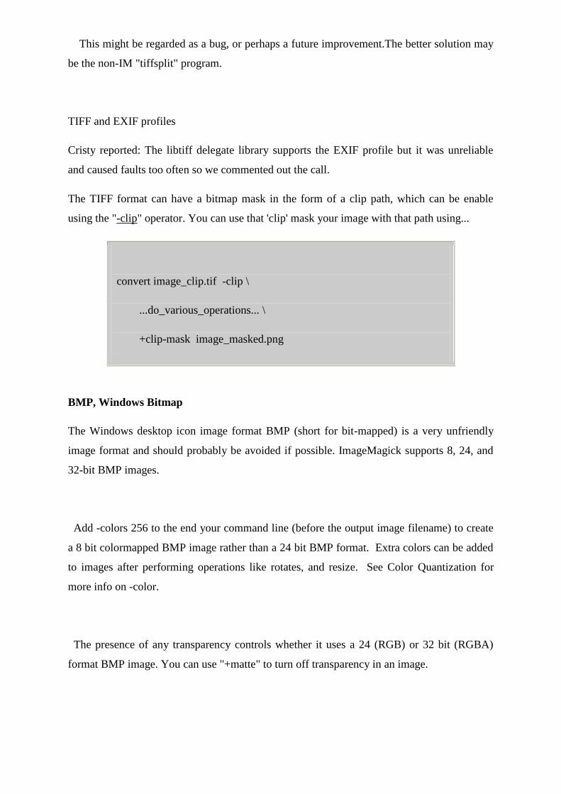
This might be regarded as a bug, or perhaps a future improvement.The better solution may
be the non-IM "tiffsplit" program.
TIFF and EXIF profiles
Cristy reported: The libtiff delegate library supports the EXIF profile but it was unreliable
and caused faults too often so we commented out the call.
The TIFF format can have a bitmap mask in the form of a clip path, which can be enable
using the "-clip" operator. You can use that 'clip' mask your image with that path using...
convert image_clip.tif -clip \
...do_various_operations... \
+clip-mask image_masked.png
BMP, Windows Bitmap
The Windows desktop icon image format BMP (short for bit-mapped) is a very unfriendly
image format and should probably be avoided if possible. ImageMagick supports 8, 24, and
32-bit BMP images.
Add -colors 256 to the end your command line (before the output image filename) to create
a 8 bit colormapped BMP image rather than a 24 bit BMP format. Extra colors can be added
to images after performing operations like rotates, and resize. See Color Quantization for
more info on -color.
The presence of any transparency controls whether it uses a 24 (RGB) or 32 bit (RGBA)
format BMP image. You can use "+matte" to turn off transparency in an image.
If all colors are gray-scale a 'directcolor' greyscale image is generated.
I think -type truecolor will stop this behaviour.
If you have an older program cannot read the default BMP4 images written by
ImageMagick, (for example a Windows Background Image), you can enforce the generation
of a BMP3 format image using...
convert image BMP3:image.bmp
This format should have no transparency and should be a 'printable image', whatever that
means. In other words 'Windows' compatible.
However, if a PNG input file was used and it contains a gAMA and cHRM chunk (gamma
and chromaticity information) either of which forces "convert" to write a BMP4. To get a
BMP3 you need to get rid of that information. One way may be to pipeline the image though
a minimal 'image data only' image file format like PPM and then re-save as BMP3. Messy,
but it should work.
convert image.png ppm:- | convert - BMP3:image.bpm
IM can not produce BMP's at depth levels other than 8. However you can use NetPBM
image processing set to do the final conversion to other depth levels (This needs at least a
Q16 version of IM)...
convert image +matte -colors 16 ppm:- |\
pnmdepth 4 | ppm2bmp > image.bmp
Format limitations....
The header for a BMP2: format only allows the description of the width height and bit depth
(bits per pixel) of an image. The bit depth can be one of 1, 4, 8 or 24. For comparison, the
bmp3: format allows bit depths of 0, 1, 4, 8 ,16, 24 and 32 and has extra fields which specify
x and y resolution (in pixels per metre) and compression of the image data.
QUESTIONS
1. What benefits are achieved by using compression in multimedia system?
2. Draw block diagram of video compression technique? And describe simple video
compression technique.
3. Write short note on color, gray scale and still image compression.
4. Explain MPEG architecture and different kind of picture used with neat sketch of
frames.
5. Describe different color models in details.
6. Describe TIFF architecture with diagram.
7. Explain transform coding video compression technique in brief.
8. Draw and explain sequential encoding JPEG image compression technique.
9. Describe the structure of TIFF file format. State 4 specifications of TIFF file format.
10. Discuss MPEG file format.
11. Compare RIFF and AVI file format.
12. Explain JPEG-DCT encoding & quantization.
13. What are I, P, B and D pictures related to MPEG coding.
14. Define the following terms related to TIFF:
i) Basic Tag field ii) Information Field iii) Facsimile fields iv) Document storage
15. Explain JPEG objectives.
16. Describe simple video compression technique.
17. What is JPEG? Write full form of RTF and RIFF.
18. Describe Lossless compression with one real life example.
19. Justify the need of compression.
20. Explain any two simple compression techniques.
21. Why compression and decompression are used in multimedia system.
22. Explain JPEG architecture with block diagrams.
23. Explain lossless and lossy compression with example.
24. Explain resource interchange file format in brief.
CHAPTER 3
AUDIO & VIDEO
DIGITAL REPRESENTATION OF SOUND(MH)
Sound results from the mechanical disturbance of some object in a physical medium such as
air. These mechanical disturbances generate vibrations that can be converted into an analog
signal (time-varying voltage) by means of devices such as a microphone. Analog signals are
continuous in the sense that they consist of a continuum of values as opposed to stepwise
values. Digital computers, however, are not analog machines. They fundamentally deal only
with binary numbers. In contrast to the decimal numeric system, which uses 10 different
symbols (i.e., from 0 to 9) to represent numbers, the binary system uses only two symbols: 0
and 1. Currently available computers are made of tiny electronic switches, each of which can
be in one of two states at a time: on or off, represented by the digits ‗‗1‘‘ and ‗‗0‘‘,
respectively. Consequently, the smallest unit of information that such computer can handle is
the bit, a contraction of the term ‗‗binary digit.‘‘ For example, the decimal numbers 0, 1, 2,
and 3 are represented in the binary system as 0, 1, 10, and 11, respectively. A digital
computer is normally configured to function based upon strings of bits of fixed size, referred
to as words. For example, a computer configured for 4-bit words would represent the decimal
numbers 0, 1, 2, and 3 as 0000, 0001, 0010, and 0011, respectively. Note that the maximum
number that 4 bits can represent is 1111, which is equal to 15 in the decimal system. In this
case, a 4-bit computer seems to be extremely limited, but in fact, even a much larger word
size would present this type of limitation. Most currently available computers use 32- or 64-
bit words, but they represent numbers in a slightly different way: They consider each digit of
a decimal number individually.
Hence, a 4-bit computer would use two separate words to represent the decimal number 15,
one for the digit 1 and another for the digit 5: 15 ¼ 0001 0101. The binary representation
discussed above is extremely useful because computers also need to represent things other
than numbers. Manufacturers assign arbitrary codes for such symbols, for instance, the letter
A ¼ 10000001 and the letterB¼10000010. Whereas part of this codification is standard for
most machines (e.g., the ASCII codification), a significant proportion is not, which leads to
one cause of incompatibility between different systems. To process sounds on the computer,
the analog sound signal must be represented using binary numbers. Conversely, the digital
signal must be converted into analog voltage to play a sound from the computer. The
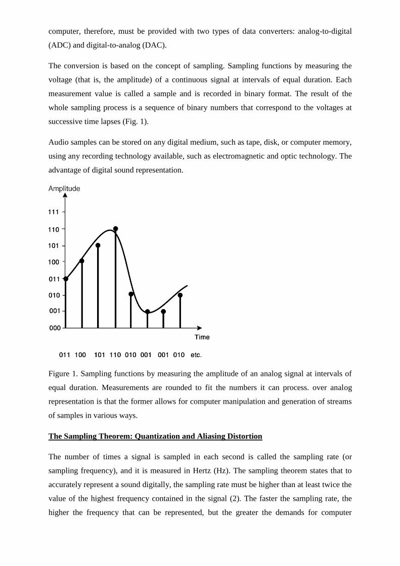
computer, therefore, must be provided with two types of data converters: analog-to-digital
(ADC) and digital-to-analog (DAC).
The conversion is based on the concept of sampling. Sampling functions by measuring the
voltage (that is, the amplitude) of a continuous signal at intervals of equal duration. Each
measurement value is called a sample and is recorded in binary format. The result of the
whole sampling process is a sequence of binary numbers that correspond to the voltages at
successive time lapses (Fig. 1).
Audio samples can be stored on any digital medium, such as tape, disk, or computer memory,
using any recording technology available, such as electromagnetic and optic technology. The
advantage of digital sound representation.
Figure 1. Sampling functions by measuring the amplitude of an analog signal at intervals of
equal duration. Measurements are rounded to fit the numbers it can process. over analog
representation is that the former allows for computer manipulation and generation of streams
of samples in various ways.
The Sampling Theorem: Quantization and Aliasing Distortion
The number of times a signal is sampled in each second is called the sampling rate (or
sampling frequency), and it is measured in Hertz (Hz). The sampling theorem states that to
accurately represent a sound digitally, the sampling rate must be higher than at least twice the
value of the highest frequency contained in the signal (2). The faster the sampling rate, the
higher the frequency that can be represented, but the greater the demands for computer
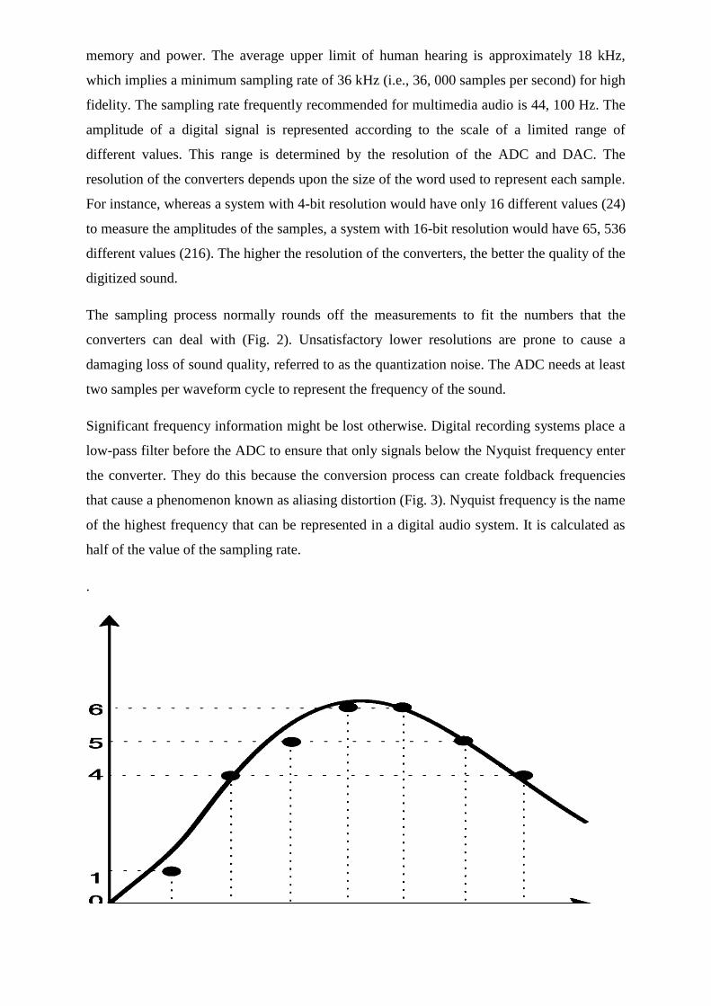
memory and power. The average upper limit of human hearing is approximately 18 kHz,
which implies a minimum sampling rate of 36 kHz (i.e., 36, 000 samples per second) for high
fidelity. The sampling rate frequently recommended for multimedia audio is 44, 100 Hz. The
amplitude of a digital signal is represented according to the scale of a limited range of
different values. This range is determined by the resolution of the ADC and DAC. The
resolution of the converters depends upon the size of the word used to represent each sample.
For instance, whereas a system with 4-bit resolution would have only 16 different values (24)
to measure the amplitudes of the samples, a system with 16-bit resolution would have 65, 536
different values (216). The higher the resolution of the converters, the better the quality of the
digitized sound.
The sampling process normally rounds off the measurements to fit the numbers that the
converters can deal with (Fig. 2). Unsatisfactory lower resolutions are prone to cause a
damaging loss of sound quality, referred to as the quantization noise. The ADC needs at least
two samples per waveform cycle to represent the frequency of the sound.
Significant frequency information might be lost otherwise. Digital recording systems place a
low-pass filter before the ADC to ensure that only signals below the Nyquist frequency enter
the converter. They do this because the conversion process can create foldback frequencies
that cause a phenomenon known as aliasing distortion (Fig. 3). Nyquist frequency is the name
of the highest frequency that can be represented in a digital audio system. It is calculated as
half of the value of the sampling rate.
.
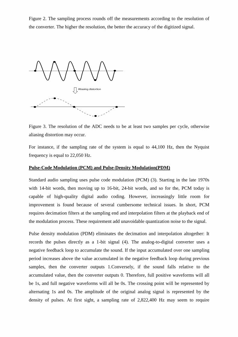
Figure 2. The sampling process rounds off the measurements according to the resolution of
the converter. The higher the resolution, the better the accuracy of the digitized signal.
Figure 3. The resolution of the ADC needs to be at least two samples per cycle, otherwise
aliasing distortion may occur.
For instance, if the sampling rate of the system is equal to 44,100 Hz, then the Nyquist
frequency is equal to 22,050 Hz.
Pulse-Code Modulation (PCM) and Pulse-Density Modulation(PDM)
Standard audio sampling uses pulse code modulation (PCM) (3). Starting in the late 1970s
with 14-bit words, then moving up to 16-bit, 24-bit words, and so for the, PCM today is
capable of high-quality digital audio coding. However, increasingly little room for
improvement is found because of several cumbersome technical issues. In short, PCM
requires decimation filters at the sampling end and interpolation filters at the playback end of
the modulation process. These requirement add unavoidable quantization noise to the signal.
Pulse density modulation (PDM) eliminates the decimation and interpolation altogether: It
records the pulses directly as a 1-bit signal (4). The analog-to-digital converter uses a
negative feedback loop to accumulate the sound. If the input accumulated over one sampling
period increases above the value accumulated in the negative feedback loop during previous
samples, then the converter outputs 1.Conversely, if the sound falls relative to the
accumulated value, then the converter outputs 0. Therefore, full positive waveforms will all
be 1s, and full negative waveforms will all be 0s. The crossing point will be represented by
alternating 1s and 0s. The amplitude of the original analog signal is represented by the
density of pulses. At first sight, a sampling rate of 2,822,400 Hz may seem to require
prohibitive storage capacity and computer power. But this should not be the case. A standard
stereo CD uses 16-bit word samples, thus the bit rate per channel here is 16 times 44.1 kHz,
that is 705, 600 bits per second. As PDM uses 1-bit per sample, the bit rate of 2 8224 MHz is
only about four times higher than for a standard CD.
The result of PDM gives an unparalleled impression of depth and fluidity that comes from a
far greater frequency response and dynamic range. PDM captures harmonics inaudible as
pure tones by accurately reproducing the leading edges of transients, which enriches the
sound spectrum and enhances the listening experience.
Sound Storage: File Formats and Compression
Digital audio may be stored on a computer in various formats. Different systems use different
formats, which define how samples and other related information are organized in a file. The
most basic way to store a sound is to take a stream of samples and save them into a file. This
method, however, is not flexible because it does not allow for the storage of information
other than the raw samples themselves, for example, the sampling rate used, the size of the
word, or whether the sound is mono or stereo. To alleviate this problem, sound files normally
include a descriptive data structure, referred to as the sound file header. Some sound file
headers allow for the inclusion of text comments and cue pointers in the sound. The most
used sound file formats are WAVE (.wav) and AIFF (.aif)
A major disadvantage of raw sound file storage is that it is uneconomical, as it might contain
a great deal of redundant information that would not need high sampling rate accuracy for
representation. As a rough illustration, imagine a mono sound file, with a sampling rate of
44.1 kHz and 16-bit words, containing a sound sequence with recurrent 3 minute-long
silences separating the sounds. In this case, 2, 116, 899 bits would be required to represent
each of these silent portions. A compression scheme could be devised to replace the raw
sampling representation of the silent portions with a code that instructs the playback device to
produce 3 seconds of silence.
Several methods are found for compressing the representation of sound samples to reduce the
size of the file. One of the most popularly known methods in use today is MPEG3 (short for
moving picture experts group layer 3), popularly known as MP3 (5). Originated by the
Internet Standards Organization (ISO), MPEG3 works by eliminating sound components that
would not normally be audible to humans. MPEG3 can compress a sound file considerably
without much noticeable difference. Other well-known compression schemes include Real
Audio (by Progressive Networks), ATRAC3 (by Sony) and WMA (by Microsoft). RealAudio
is acknowledged as the first compression format to support live audio over the
Internet.ATRAC3is a sound compression technology based on ATRAC, the technology that
Sony devised originally for the MiniDisc.
SOUND PROCESSING TECHNOLOGY BACKGROUND
In general, a filter is any device that performs some sort of transformation on a signal. For
simplicity, however, we refer only to those filters that remove or favor the resonance of
specific components of the spectrum of a signal, namely, low-pass (LPF), high-pass (HPF),
band-pass (BPF), and band-reject (BRF).
The BPF, also known as the resonator, rejects both high and low frequencies with a passband
in between. Two parameters are used to specify the characteristics of a BPF: passband center
frequency (represented as fc) and resonance bandwidth (represented as bw). The bw
parameter comprises the difference between the upper (represented as fu) and lower
(represented as fl) cutoff frequencies (Fig. 4).
The BRF amplitude response is the inverse of a BPF. It attenuates a single band of
frequencies and discounts all others. Like a BPF, it is characterized by a central frequency
and a bandwidth, but another important parameter is the amount of attenuation in the center
of the stopband.
An LPF permits frequencies below the point called the
cutoff frequency to pass with little change. However, it
reduces the amplitude of spectral components above the cutoff frequency. Conversely,
anHPFhas a passband above the cutoff frequency where signals are passed and a stopband
below the cutoff frequency where the signals are attenuated. Always a smooth transition
occurs between passband and stopband. It is often defined as the frequency
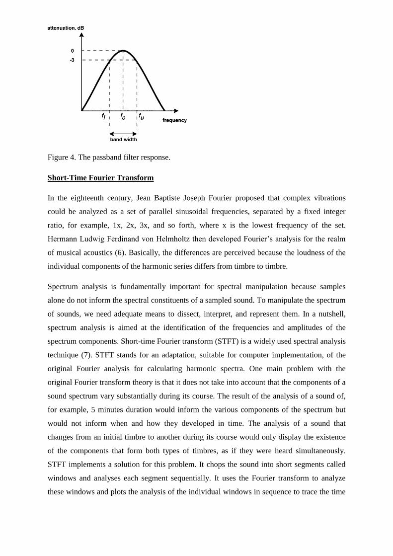
Figure 4. The passband filter response.
Short-Time Fourier Transform
In the eighteenth century, Jean Baptiste Joseph Fourier proposed that complex vibrations
could be analyzed as a set of parallel sinusoidal frequencies, separated by a fixed integer
ratio, for example, 1x, 2x, 3x, and so forth, where x is the lowest frequency of the set.
Hermann Ludwig Ferdinand von Helmholtz then developed Fourier‘s analysis for the realm
of musical acoustics (6). Basically, the differences are perceived because the loudness of the
individual components of the harmonic series differs from timbre to timbre.
Spectrum analysis is fundamentally important for spectral manipulation because samples
alone do not inform the spectral constituents of a sampled sound. To manipulate the spectrum
of sounds, we need adequate means to dissect, interpret, and represent them. In a nutshell,
spectrum analysis is aimed at the identification of the frequencies and amplitudes of the
spectrum components. Short-time Fourier transform (STFT) is a widely used spectral analysis
technique (7). STFT stands for an adaptation, suitable for computer implementation, of the
original Fourier analysis for calculating harmonic spectra. One main problem with the
original Fourier transform theory is that it does not take into account that the components of a
sound spectrum vary substantially during its course. The result of the analysis of a sound of,
for example, 5 minutes duration would inform the various components of the spectrum but
would not inform when and how they developed in time. The analysis of a sound that
changes from an initial timbre to another during its course would only display the existence
of the components that form both types of timbres, as if they were heard simultaneously.
STFT implements a solution for this problem. It chops the sound into short segments called
windows and analyses each segment sequentially. It uses the Fourier transform to analyze
these windows and plots the analysis of the individual windows in sequence to trace the time
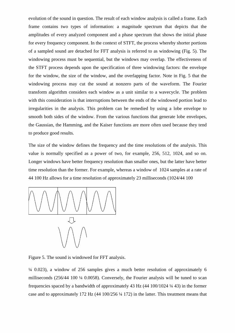
evolution of the sound in question. The result of each window analysis is called a frame. Each
frame contains two types of information: a magnitude spectrum that depicts that the
amplitudes of every analyzed component and a phase spectrum that shows the initial phase
for every frequency component. In the context of STFT, the process whereby shorter portions
of a sampled sound are detached for FFT analysis is referred to as windowing (Fig. 5). The
windowing process must be sequential, but the windows may overlap. The effectiveness of
the STFT process depends upon the specification of three windowing factors: the envelope
for the window, the size of the window, and the overlapping factor. Note in Fig. 5 that the
windowing process may cut the sound at nonzero parts of the waveform. The Fourier
transform algorithm considers each window as a unit similar to a wavecycle. The problem
with this consideration is that interruptions between the ends of the windowed portion lead to
irregularities in the analysis. This problem can be remedied by using a lobe envelope to
smooth both sides of the window. From the various functions that generate lobe envelopes,
the Gaussian, the Hamming, and the Kaiser functions are more often used because they tend
to produce good results.
The size of the window defines the frequency and the time resolutions of the analysis. This
value is normally specified as a power of two, for example, 256, 512, 1024, and so on.
Longer windows have better frequency resolution than smaller ones, but the latter have better
time resolution than the former. For example, whereas a window of 1024 samples at a rate of
44 100 Hz allows for a time resolution of approximately 23 milliseconds (1024/44 100
Figure 5. The sound is windowed for FFT analysis.
¼ 0.023), a window of 256 samples gives a much better resolution of approximately 6
milliseconds (256/44 100 ¼ 0.0058). Conversely, the Fourier analysis will be tuned to scan
frequencies spaced by a bandwidth of approximately 43 Hz (44 100/1024 ¼ 43) in the former
case and to approximately 172 Hz (44 100/256 ¼ 172) in the latter. This treatment means that
a window of 256 samples is not suitable for the analysis of sounds lower than 172 Hz, but it
may suit the analysis of a sound that is likely to present important fluctuation within less than
23 milliseconds.
To find out precisely when an event occurs, the Fourier analysis algorithm cuts down the
frequency resolution and vice versa. The overlapping of successive windows can alleviate
this problem. For example, if an overlap factor is set to equal 16 (i.e., 1/16th of the size of the
window), and if the window size is set to equal 1024 samples, then the windowing process
will slice the sound in steps of 64 samples (i.e., 1024/16¼64). In this case, the time resolution
of a window of 1024 samples would improve from 23 milliseconds to approximately 1.4
milliseconds (i.e., 0.023/16 ¼ 0.0014).
Analog-to-Digital Voice Encoding Basic Voice Encoding: Converting Analog to Digital
Digitizing Analog Signals
1. Sample the analog signal regularly.
2. Quantize the sample.
3. Encode the value into a binary expression.
4. Compress the samples to reduce bandwidth, optional step.
Digitizing speech was a project first undertaken by the Bell System in the 1950s. The original
purpose of digitizing speech was to deploy more voice circuits with a smaller number of
wires. This evolved into the T1 and E1 transmission methods of today.
To convert an analog signal to a digital signal, you must perform these steps:
Analog-to-Digital Signal Conversion Step Procedure Description
1. Sample the analog signal regularly. The sampling rate must be twice the highest frequency
to produce playback that appears neither choppy nor too smooth.
2. Quantize the sample. Quantization consists of a scale made up of eight major divisions or
chords. Each chord is subdivided into 16 equally spaced steps. The chords are not equally
spaced but are actually finest near the origin. Steps are equal within the chords but different
when they are compared between the chords. Finer graduations at the origin result in less
distortion for low-level tones.
3. Encode the value into 8-bit digital form. PBX output is a continuous analog voice
waveform. T1 digital voice is a snapshot of the wave encoded in ones and zeros.
4. (Optional) Compress the samples to reduce bandwidth. Although not essential to convert
analog signals to digital, signal compression is widely used to reduce bandwidth. The three
components in the analog-to-digital conversion process are further described as follows:
� Sampling: Sample the analog signal at periodic intervals. The output of sampling is a
pulse amplitude modulation (PAM) signal.
� Quantization: Match the PAM signal to a segmented scale. This scale measures the
amplitude (height) of the PAM signal and assigns an integer number to define that amplitude.
� Encoding: Convert the integer base-10 number to a binary number. The output of
encoding is a binary expression in which each bit is either a 1 (pulse) or a 0 (no pulse).
This three-step process is repeated 8000 times per second for telephone voice-channel
service. Use the fourth optional step—compression—to save bandwidth. This optional step
allows a single channel to carry more voice calls.
Basic Voice Encoding: Converting Digital to Analog
Basic Voice Encoding: Converting Digital to Analog 1. Decompress the samples, if
compressed. 2. Decode the samples into voltage amplitudes, rebuilding the PAM signal.
3. Filter the signal to remove any noise.
After the receiving terminal at the far end receives the digital PCM signal, it must convert the
PCM signal back into an analog signal. The process of converting digital signals back into
analog signals includes the following two steps:
� Decoding: The received 8-bit word is decoded to recover the number that defines the
amplitude of that sample. This information is used to rebuild a PAM signal of the original
amplitude. This process is simply the reverse of the analog-to-digital conversion.
� Filtering: The PAM signal is passed through a properly designed filter that reconstructs
the original analog wave form from its digitally coded counterpart.
Voice Compression and Codec Standards
Voice Compression Techniques
• Waveform algorithms PCM ADPCM
• Source algorithms LDCELP CS-ACELP
The following describes the two voice compression techniques:
� Waveform algorithms (coders): Waveform algorithms have the following functions and
characteristics: — Sample analog signals at 8000 times per second — Use predictive
differential methods to reduce bandwidth — Highly impact voice quality because of reduced
bandwith — Do not take advantage of speech characteristics
� Source algorithms (coders): Source algorithms have the following functions and
characteristics: — Source algorithm coders are called vocoders, or voice coders. A vocoder is
a device that converts analog speech into digital speech, using a specific compression scheme
that is optimized for coding human speech.
— Vocoders take advantage of speech characteristics.
— Bandwidth reduction occurs by sending linear-filter settings.
— Codebooks store specific predictive waveshapes of human speech. They match the speech,
encode the phrases, decode the waveshapes at the receiver by looking up the coded phrase,
and match it to the stored waveshape in the receiver codebook.
• PCMWaveform coding scheme
• ADPCM Waveform coding scheme Adaptive: automatic companding Differential:
encode changes between samples only
Adaptive differential pulse code modulation (ADPCM) coders, like other waveform coders,
encode analog voice signals into digital signals to adaptively predict future encodings by
looking at the immediate past. The adaptive feature of ADPCM reduces the number of bits
per second that the PCM method requires to encode voice signals.
ADPCM does this by taking 8000 samples per second of the analog voice signal and turning
them into a linear PCM sample. ADPCM then calculates the predicted value of the next
sample, based on the immediate past sample, and encodes the difference. The ADPCM
process generates 4-bit words, thereby generating 16 specific bit patterns. The ADPCM
algorithm from the Consultative Committee for International Telegraph and Telephone
(CCITT) transmits all 16 possible bit patterns.
The ADPCM algorithm from the American National Standards Institute (ANSI) uses 15 of
the 16 possible bit patterns. The ANSI ADPCM algorithm does not generate a 0000 pattern.
Time domain sampled representation(mh)
Digital signal processing is preferred over analog signal processing when it is feasible. Its
advantages are that the quality can be precisely controlled (via wordlength and sampling
rate), and that changes in the processing algorithm are made in software. Its disadvantages are
that it may be more expensive and that speed or throughput is limited. Between samples,
several multiplications, additions, and other numerical operations need to be performed. This
limits sampling rate, which in turn limits the bandwidth of signals that can be processed. For
example, the standard for high fidelity audio is 44,100 samples per second. This limits
bandwidth to below the half-sampling frequency of about f0 / 2 = 22 kHz, and gives the
processor only 22.7 microseconds between samples for its computations. It should be noted
here that the half-sampling frequency f0 / 2 may also be referred to as the Nyquist frequency
and the sampling rate f0 may be referred to as either the Nyquist sampling rate, Shannon
sampling rate, or critical sampling rate.
In order to do digital signal processing of analog signals, one must first sample. After the
processing is completed, a continuous time signal must be constructed. The particulars of
how this is done are addressed in this lab. We will examine
i. aliasing of different frequencies separated by integer multiples of the sampling
frequency,
ii. techniques of digital interpolation to increase the sampling rate (upsampling) and
convert to continuous time,
iii. sample rate conversion using upsampling followed by downsampling.
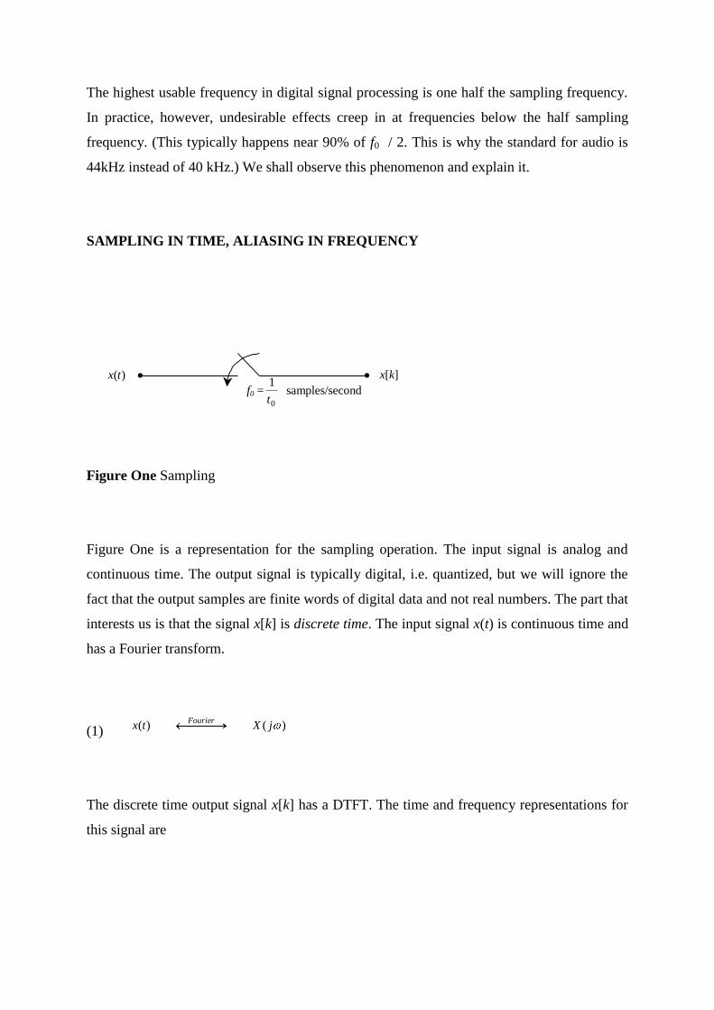
The highest usable frequency in digital signal processing is one half the sampling frequency.
In practice, however, undesirable effects creep in at frequencies below the half sampling
frequency. (This typically happens near 90% of f0 / 2. This is why the standard for audio is
44kHz instead of 40 kHz.) We shall observe this phenomenon and explain it.
SAMPLING IN TIME, ALIASING IN FREQUENCY
x[k] )(tx f0 =
0
1
tsamples/second
Figure One Sampling
Figure One is a representation for the sampling operation. The input signal is analog and
continuous time. The output signal is typically digital, i.e. quantized, but we will ignore the
fact that the output samples are finite words of digital data and not real numbers. The part that
interests us is that the signal x[k] is discrete time. The input signal x(t) is continuous time and
has a Fourier transform.
(1) )()( jXtxFourier
The discrete time output signal x[k] has a DTFT. The time and frequency representations for
this signal are
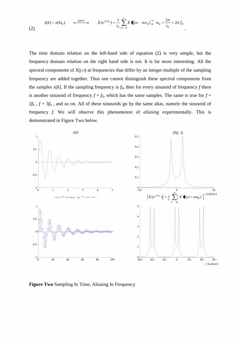
(2) 0
000
00 2
2,)(
1)()(][ 0 f
tnjX
teXktxkx
n
tjDTFT
.
The time domain relation on the left-hand side of equation (2) is very simple, but the
frequency domain relation on the right hand side is not. It is far more interesting. All the
spectral components of X(j ) at frequencies that differ by an integer multiple of the sampling
frequency are added together. Thus one cannot distinguish these spectral components from
the samples x[k]. If the sampling frequency is f0, then for every sinusoid of frequency f there
is another sinusoid of frequency f + f0, which has the same samples. The same is true for f +
2f0 , f + 3f0 , and so on. All of these sinusoids go by the same alias, namely the sinusoid of
frequency f. We will observe this phenomenon of aliasing experimentally. This is
demonstrated in Figure Two below.
0 1 2 3 4 5 -1
-0.5
0
0.5
1
-20
0 20
0
0.1
0.2
0.3
0.4
0.5
0 20 40 60 80 100 -1
-0.5
0
0.5
1
-60
-40
-20
0 20
40
60
0
1
2
3
4
5
|X(j )| x(t)
.sec05.0),(][ 00 tktxkx
n
t
tjnjXeX )()( 0
1
0
0 [rad/sec]
[rad/sec]
Figure Two Sampling In Time, Aliasing In Frequency
A few comments about Figure Two. The continuous-time signal x(t) is a dampened sinusoid
defined by
(3) ),()10sin()( tutetx t
were u(t) is the unit step function. This signal could be an example of a natural response of an
underdamped parallel RLC circuit. The spectrum of x(t) is a commonly known Laplace
transform given by
(4) jsjs ss
sXjX1012
10)()(
2
which is shown in the upper right panel of Figure Two. From this graph, it can be seen that
X(j ) is essentially bandlimited to the frequency band –20 20 . This is to say that the
frequency components | | > 20 contain much less energy than the frequency components of
| | 20 . In practice, the signal x(t) will be guaranteed to be bandlimited by an analog
lowpass filter called an anti-aliasing filter. The Shannon sampling theorem then says that we
need to sample at a rate twice the maximum frequency component of our bandlimited signal.
In our case, this means that our sampling frequency will be 0 = 40 . (Also,
sec05.0,2000
0 12020 f
tandHzf.) In accordance with the Shannon sampling
theorem, x(t) was sampled at rate 0 = 40 rad/sec. The sample data signal is shown in the
lower left panel of Figure Two and the accompanying discrete-time frequency response is
shown in the lower right panel. Notice the marks on the frequency axis of the lower right
panel. These marks show where the aliases of the original signal are centered. As the
sampling rate increases, the center frequencies of the X(j ) aliases will move farther away
from the original signal‘s spectrum. In Figure Two, the sampling frequency 0 prevents a
noticeable overlap of aliases, leaving )( 0tjeX looking essentially like X(j ). Thus aliasing
effects are minimized. Aliasing effects due to undersampling amount to a set of samples that
appear to be the samples of a signal with a lower frequency, hence the term alias. This is to
be avoided since these effects cannot be removed in digital processing. To prevent this, one
should sample at the Nyquist sampling rate or higher.
THE DISCRETE-TIME TO CONTINOUS TIME RECONSTRUCTION PROCESS
Let us state an unwelcome fact. Given the input x(t), one can easily get the output samples
x[k], but the reverse is not true. Given the output samples, we cannot reconstruct the input
without knowing extra information, because we have thrown out everything between the
samples. Obviously there are infinitely many ways to fill in the gaps between samples. The
sampling operation is many to one, and is not generally invertible. However, if the input is
band limited to the half sampling frequency, then there will be exactly one input signal x(t)
for the given set of samples. This is the Shannon sampling theorem, and the bandlimited
reconstruction is (5) k
ktthkxtx )(][)( 0
, where 0/sinc=)( ttth .
Equation (5) represents the ideal. It is the goal of a good analog reconstruction design to
approximate this relation. Therefore, make note of two things: first, equation (5) is a pulse
amplitude modulation (PAM) equation, and second, the PAM pulseshape is that of the sinc
function, or Shannon wavelet. The sinc function in question is the impulse response of an
ideal lowpass filter with gain equal to the sampling period 0t , and bandwidth one half the
sampling frequency, hence the term bandlimited reconstruction. One departure from the ideal
is allowed in audio systems. Time delay is of no consequence, and therefore one can use a
delayed sinc pulse. In digital feedback control systems however, time delay can present
stability problems and is to be avoided. The time domain process of reconstructing x(t) from
its samples x[k] is demonstrated in Figure Three below.
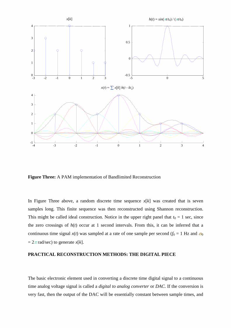
-3 -2 -1 0 1 2 3 0
1
2
3
4
-5 0 5 -0.5
0
0.5
1
-4 -3 -2 -1 0 1 2 3 4 -1
0
1
2
3
4
x[k] h(t) = sin( t/t0) / ( t/t0)
x(t) = x[k] h(t - kt0)
Figure Three: A PAM implementation of Bandlimited Reconstruction
In Figure Three above, a random discrete time sequence x[k] was created that is seven
samples long. This finite sequence was then reconstructed using Shannon reconstruction.
This might be called ideal construction. Notice in the upper right panel that t0 = 1 sec, since
the zero crossings of h(t) occur at 1 second intervals. From this, it can be inferred that a
continuous time signal x(t) was sampled at a rate of one sample per second (f0 = 1 Hz and 0
= 2 rad/sec) to generate x[k].
PRACTICAL RECONSTRUCTION METHODS: THE DIGITAL PIECE
The basic electronic element used in converting a discrete time digital signal to a continuous
time analog voltage signal is called a digital to analog converter or DAC. If the conversion is
very fast, then the output of the DAC will be essentially constant between sample times, and
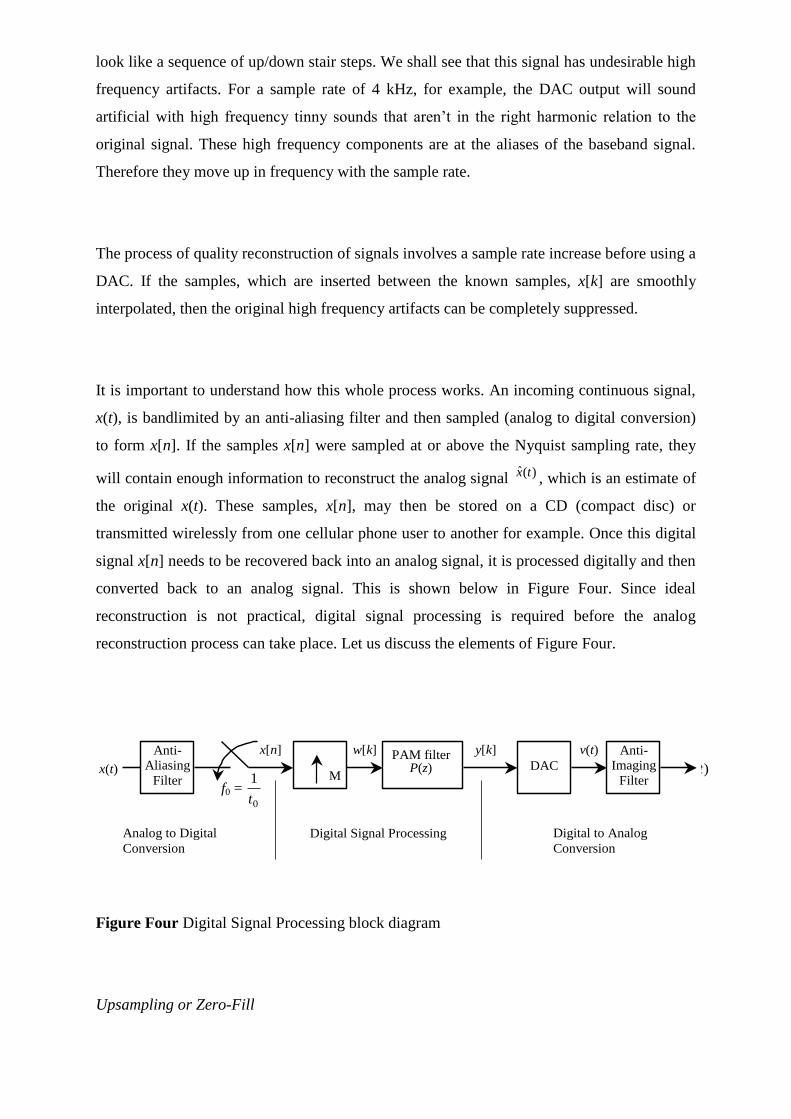
look like a sequence of up/down stair steps. We shall see that this signal has undesirable high
frequency artifacts. For a sample rate of 4 kHz, for example, the DAC output will sound
artificial with high frequency tinny sounds that aren‘t in the right harmonic relation to the
original signal. These high frequency components are at the aliases of the baseband signal.
Therefore they move up in frequency with the sample rate.
The process of quality reconstruction of signals involves a sample rate increase before using a
DAC. If the samples, which are inserted between the known samples, x[k] are smoothly
interpolated, then the original high frequency artifacts can be completely suppressed.
It is important to understand how this whole process works. An incoming continuous signal,
x(t), is bandlimited by an anti-aliasing filter and then sampled (analog to digital conversion)
to form x[n]. If the samples x[n] were sampled at or above the Nyquist sampling rate, they
will contain enough information to reconstruct the analog signal )(ˆ tx , which is an estimate of
the original x(t). These samples, x[n], may then be stored on a CD (compact disc) or
transmitted wirelessly from one cellular phone user to another for example. Once this digital
signal x[n] needs to be recovered back into an analog signal, it is processed digitally and then
converted back to an analog signal. This is shown below in Figure Four. Since ideal
reconstruction is not practical, digital signal processing is required before the analog
reconstruction process can take place. Let us discuss the elements of Figure Four.
x[n]
M
w[k] PAM filter P(z)
y[k]
x(t)
Analog to Digital
Conversion
Digital Signal Processing Digital to Analog
Conversion
)(ˆ tx
f0 = 0
1
t
Anti-
Aliasing
Filter
DAC
Anti-
Imaging
Filter
v(t)
Figure Four Digital Signal Processing block diagram
Upsampling or Zero-Fill
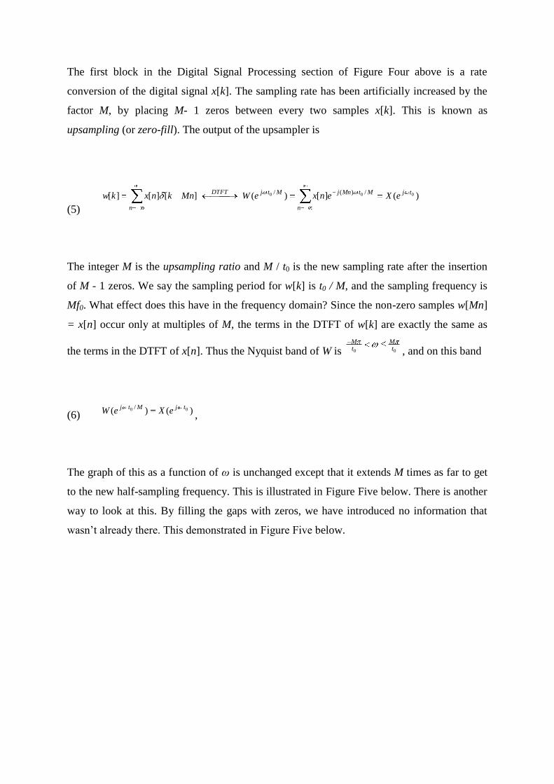
The first block in the Digital Signal Processing section of Figure Four above is a rate
conversion of the digital signal x[k]. The sampling rate has been artificially increased by the
factor M, by placing M- 1 zeros between every two samples x[k]. This is known as
upsampling (or zero-fill). The output of the upsampler is
(5)
)(][)(][][][ 000 /)(/ tj
n
MtMnjMtjDTFT
n
eXenxeWMnknxkw
The integer M is the upsampling ratio and M / t0 is the new sampling rate after the insertion
of M - 1 zeros. We say the sampling period for w[k] is t0 / M, and the sampling frequency is
Mf0. What effect does this have in the frequency domain? Since the non-zero samples w[Mn]
= x[n] occur only at multiples of M, the terms in the DTFT of w[k] are exactly the same as
the terms in the DTFT of x[n]. Thus the Nyquist band of W is 00 tM
tM
, and on this band
(6) )()( 00 / tjMtjeXeW ,
The graph of this as a function of ω is unchanged except that it extends M times as far to get
to the new half-sampling frequency. This is illustrated in Figure Five below. There is another
way to look at this. By filling the gaps with zeros, we have introduced no information that
wasn‘t already there. This demonstrated in Figure Five below.
-140 -120 -100 -80 -60 -40 -20 0 20 40 60 80 100 120 140 0
-140 -120 -100 -80 -60 -40 -20 0 20 40 60 80 100 120 140 0
X(e j
). The Half Sampling Frequency 0 / 2 is Marked.
Nyquist Band
W(e j / M
). M = 4. The Half Sampling Frequency M 0 / 2 is Marked.
[rad/sec]
Nyquist Band [rad/sec]
X X
X X
Figure Five Zero-Fill Upsampling Interpreted in the Frequency Domain
Notice that the original signal X(e j
) has a Nyquist band of 20 (-10 to 10 ) and W(e j
) has
a Nyquist band of 4*20 = 80 (-40 to 40 ), yet the frequency content is the same in both
graphs. Only the Nyquist band has changed as a result of w[k] having a higher sample rate
than x[n].
Upsampling with a discrete-time PAM Filter
The second block in the Digital Signal Processing section of Figure Four above is a digital
filter, which is used for digital interpolation. This filter is also called a discrete-time PAM
filter. The output of this filter is the convolution of the zero-filled sequence w[k] with the
pulse response of a PAM (or smoothing) filter p[k]:
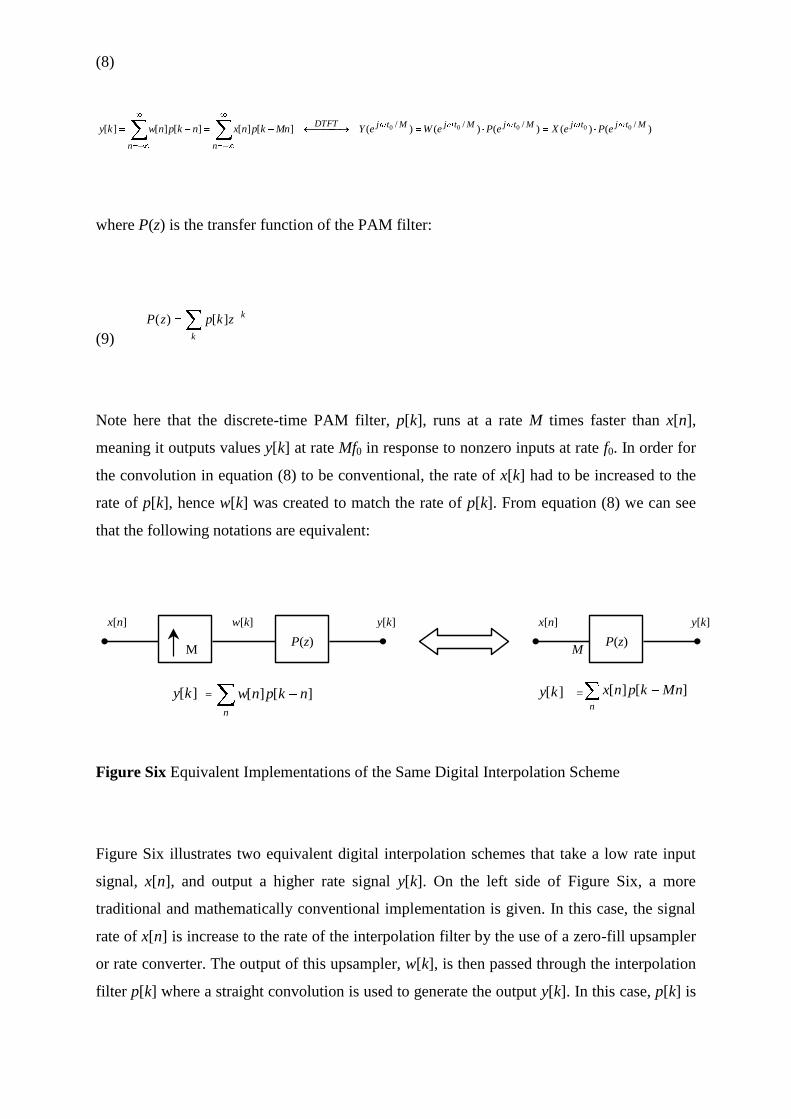
(8)
)()()()()(][][][][][//// 00000 MtjtjMtjMtjMtjDTFT
nn
ePeXePeWeYMnkpnxnkpnwky
where P(z) is the transfer function of the PAM filter:
(9) k
kzkpzP ][)(
Note here that the discrete-time PAM filter, p[k], runs at a rate M times faster than x[n],
meaning it outputs values y[k] at rate Mf0 in response to nonzero inputs at rate f0. In order for
the convolution in equation (8) to be conventional, the rate of x[k] had to be increased to the
rate of p[k], hence w[k] was created to match the rate of p[k]. From equation (8) we can see
that the following notations are equivalent:
x[n]
M
w[k]
P(z)
][ky =
n
nkpnw ][][
P(z) M
x[n]
][ky = n
Mnkpnx ][][
y[k] y[k]
Figure Six Equivalent Implementations of the Same Digital Interpolation Scheme
Figure Six illustrates two equivalent digital interpolation schemes that take a low rate input
signal, x[n], and output a higher rate signal y[k]. On the left side of Figure Six, a more
traditional and mathematically conventional implementation is given. In this case, the signal
rate of x[n] is increase to the rate of the interpolation filter by the use of a zero-fill upsampler
or rate converter. The output of this upsampler, w[k], is then passed through the interpolation
filter p[k] where a straight convolution is used to generate the output y[k]. In this case, p[k] is
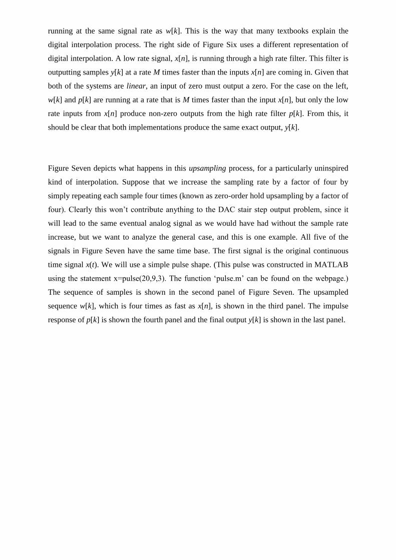
running at the same signal rate as w[k]. This is the way that many textbooks explain the
digital interpolation process. The right side of Figure Six uses a different representation of
digital interpolation. A low rate signal, x[n], is running through a high rate filter. This filter is
outputting samples y[k] at a rate M times faster than the inputs x[n] are coming in. Given that
both of the systems are linear, an input of zero must output a zero. For the case on the left,
w[k] and p[k] are running at a rate that is M times faster than the input x[n], but only the low
rate inputs from x[n] produce non-zero outputs from the high rate filter p[k]. From this, it
should be clear that both implementations produce the same exact output, y[k].
Figure Seven depicts what happens in this upsampling process, for a particularly uninspired
kind of interpolation. Suppose that we increase the sampling rate by a factor of four by
simply repeating each sample four times (known as zero-order hold upsampling by a factor of
four). Clearly this won‘t contribute anything to the DAC stair step output problem, since it
will lead to the same eventual analog signal as we would have had without the sample rate
increase, but we want to analyze the general case, and this is one example. All five of the
signals in Figure Seven have the same time base. The first signal is the original continuous
time signal x(t). We will use a simple pulse shape. (This pulse was constructed in MATLAB
using the statement x=pulse(20,9,3). The function ‗pulse.m‘ can be found on the webpage.)
The sequence of samples is shown in the second panel of Figure Seven. The upsampled
sequence w[k], which is four times as fast as x[n], is shown in the third panel. The impulse
response of p[k] is shown the fourth panel and the final output y[k] is shown in the last panel.
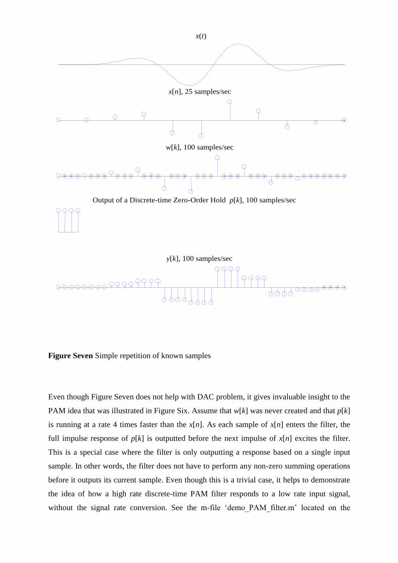
x(t)
x[n], 25 samples/sec
w[k], 100 samples/sec
y[k], 100 samples/sec
Output of a Discrete-time Zero-Order Hold p[k], 100 samples/sec
Figure Seven Simple repetition of known samples
Even though Figure Seven does not help with DAC problem, it gives invaluable insight to the
PAM idea that was illustrated in Figure Six. Assume that w[k] was never created and that p[k]
is running at a rate 4 times faster than the x[n]. As each sample of x[n] enters the filter, the
full impulse response of p[k] is outputted before the next impulse of x[n] excites the filter.
This is a special case where the filter is only outputting a response based on a single input
sample. In other words, the filter does not have to perform any non-zero summing operations
before it outputs its current sample. Even though this is a trivial case, it helps to demonstrate
the idea of how a high rate discrete-time PAM filter responds to a low rate input signal,
without the signal rate conversion. See the m-file ‗demo_PAM_filter.m‘ located on the
webpage under ‗Demos for Lab 10‘. Down load this file and run it a few times to get the feel
of how discrete-time PAM filters work. For your own amusement, re-write
‗demo_PAM_filter.m‘ to model the left half of Figure Six. Note, only the signal rate of the
input will change. The output should look exactly the same.
The frequency responses of each of the five panels in Figure Seven above are given in Figure
Eight below. Another common way to graph a complex frequency response is to use the
identity = 2 f. Now X(j ) = X(2 f ), and the frequency axis is now in Hz instead of
radians/second. This is the technique used in the following complex frequency response
graphs. The same five signals are shown with a common frequency axis. The half sampling
frequency for the four discrete-time signals are marked on the horizontal axis. Without this
mark, the second and third panels, which show )( 02 tfjeX and )(
/2 0 MtfjeW would look
exactly the same, because of equation (7). Indeed the only difference in the frequency domain
is the sampling rate. The signals in the three lowest panels are related by equation (8), i.e.
)(/2 0 Mtfj
eY is the product of the aliased spectrum )( 02 tfjeX and the interpolation filter
frequency response )(/2 0 Mtfj
eP . In Figure Eight )(/2 0 Mtfj
eP is the DTFT of a square pulse
and is a sinc pulse. Therefore the high frequency aliases in )( 02 tfjeX appear in the final
signal )(/2 0 Mtfj
eY .
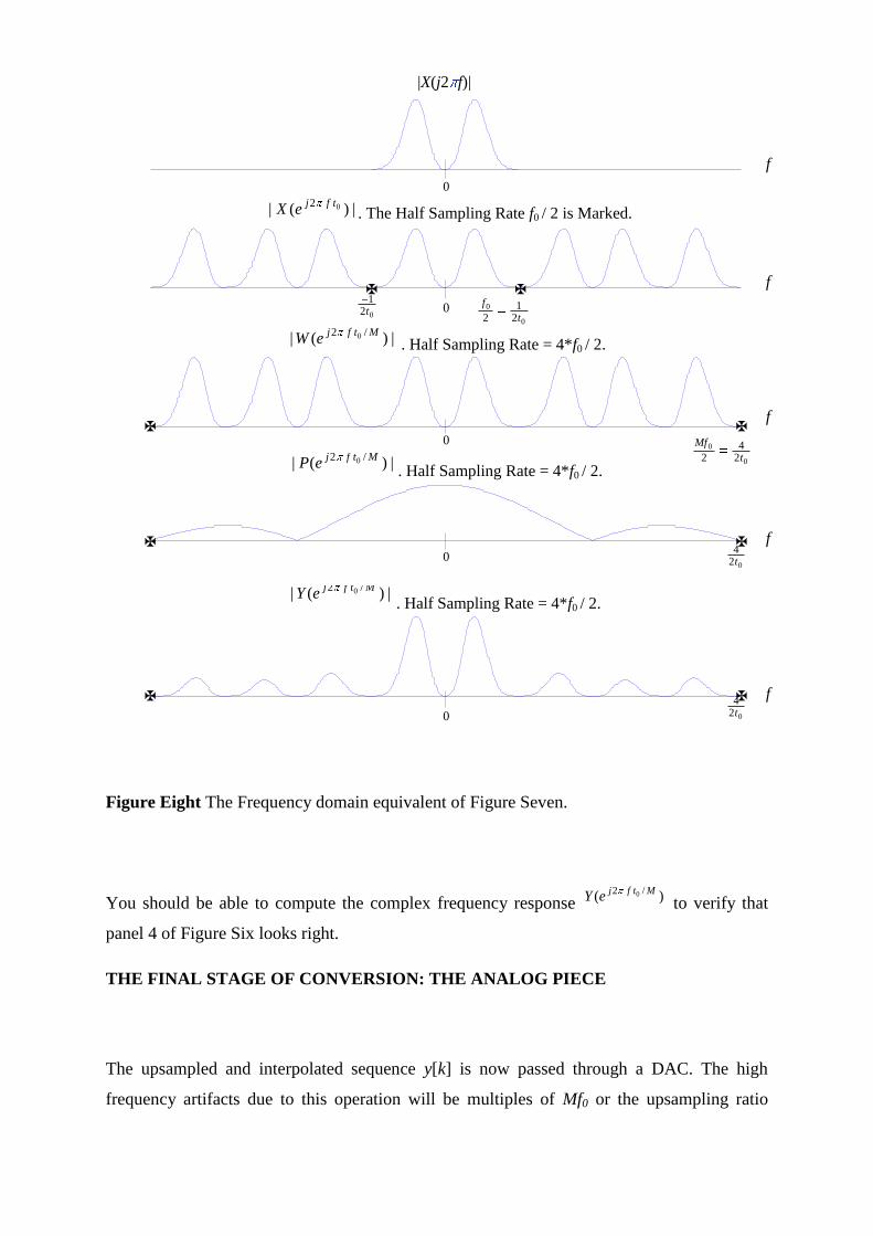
|X(j2 f)|
|)(| 02 tfjeX . The Half Sampling Rate f0 / 2 is Marked.
|)(|/2 0 Mtfj
eW . Half Sampling Rate = 4*f0 / 2.
|)(|
/2 0 MtfjeP
. Half Sampling Rate = 4*f0 / 2.
|)(|
/2 0 MtfjeY
. Half Sampling Rate = 4*f0 / 2.
0
0
21
2 t
f
021t
0
0
24
2 t
Mf
02
4t
024t
0
0
0
0
0
f
f
f
f
f
Figure Eight The Frequency domain equivalent of Figure Seven.
You should be able to compute the complex frequency response )(/2 0 Mtfj
eY to verify that
panel 4 of Figure Six looks right.
THE FINAL STAGE OF CONVERSION: THE ANALOG PIECE
The upsampled and interpolated sequence y[k] is now passed through a DAC. The high
frequency artifacts due to this operation will be multiples of Mf0 or the upsampling ratio
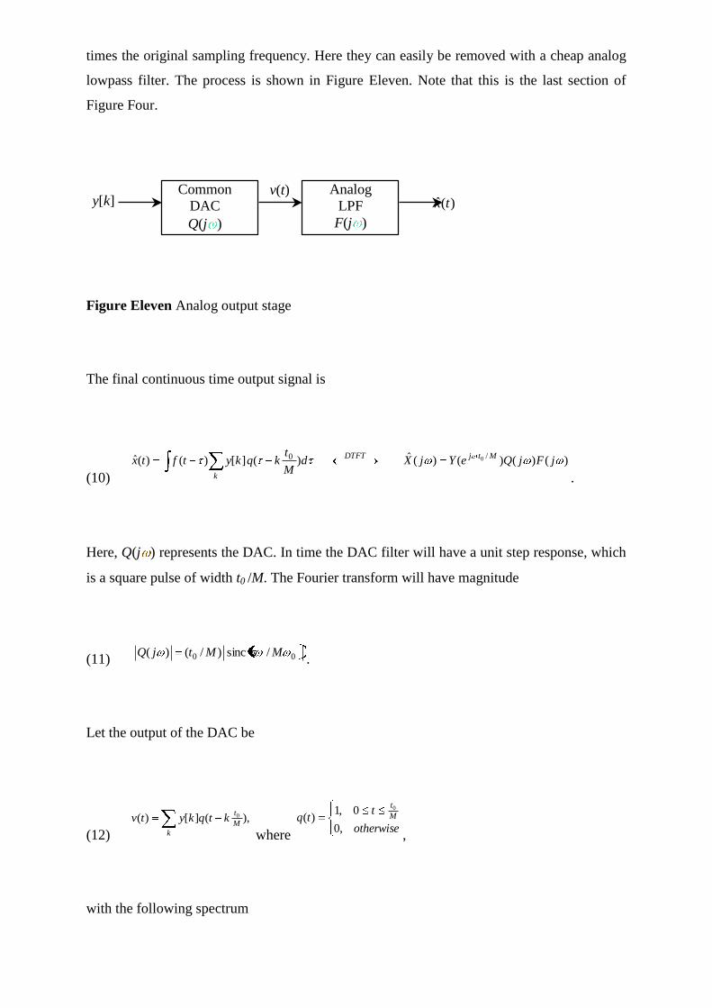
times the original sampling frequency. Here they can easily be removed with a cheap analog
lowpass filter. The process is shown in Figure Eleven. Note that this is the last section of
Figure Four.
Common
DAC
Q(j )
Analog
LPF
F(j )
y[k] v(t)
)(ˆ tx
Figure Eleven Analog output stage
The final continuous time output signal is
(10)
)()()()(ˆ)(][)()(ˆ/0 0 jFjQeYjXd
M
tkqkytftx
MtjDTFT
k .
Here, Q(j ) represents the DAC. In time the DAC filter will have a unit step response, which
is a square pulse of width t0 /M. The Fourier transform will have magnitude
(11) 00 /sinc)/()( MMtjQ.
Let the output of the DAC be
(12)
,)(][)( 0
k
M
tktqkytv
where otherwise
ttq M
t
,0
0,1)(
0
,
with the following spectrum
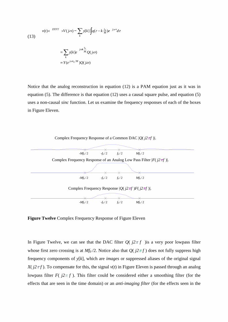
(13)
dekqkyjVtv
k
j
M
tDTFT)(][)()( 0
)()(
)(][
0
0
jQeY
jQeky
Mtj
M
tkj
k
Notice that the analog reconstruction in equation (12) is a PAM equation just as it was in
equation (5). The difference is that equation (12) uses a causal square pulse, and equation (5)
uses a non-causal sinc function. Let us examine the frequency responses of each of the boxes
in Figure Eleven.
Complex Frequency Response of a Common DAC |Q( j2 f )|.
Complex Frequency Response of an Analog Low Pass Filter |F( j2 f )|.
Complex Frequency Response |Q( j2 f )F( j2 f )|.
Mf0 / 2 -f0 / 2 -Mf0 / 2
-f0 / 2 f0 / 2 -Mf0 / 2 Mf0 / 2
f0 / 2
-Mf0 / 2 -f0 / 2 f0 / 2 Mf0 / 2
Figure Twelve Complex Frequency Response of Figure Eleven
In Figure Twelve, we can see that the DAC filter Q( j2 f )is a very poor lowpass filter
whose first zero crossing is at Mf0 /2. Notice also that Q( j2 f ) does not fully suppress high
frequency components of y[k], which are images or suppressed aliases of the original signal
X( j2 f ). To compensate for this, the signal v(t) in Figure Eleven is passed through an analog
lowpass filter F( j2 f ). This filter could be considered either a smoothing filter (for the
effects that are seen in the time domain) or an anti-imaging filter (for the effects seen in the
frequency domain). Either way, the product Q( j2 f )F( j2 f ) is then a better lowpass filter
which is essentially constant on the frequency band from -f0 /2 to f0 /2, but effectively
attenuates all frequency components above Mf0 /2. This leaves a long gap for a transition
band from f0 /2 to Mf0 /2. This is crucial because our information lies in the frequency band -f0
/2 to f0 /2, so this is the only part of the spectrum that we want. Since the alised spectrum of
Y(ej2 f t0 /M
) from f0 /2 to Mf0 /2 was taken out with digital signal processing, the final stage of
analog signal reconstruction is not critical. Any reasonable filter will work because the
difficult part has been done by the digital filter P(z). We will not simulate the final output
stage in Figure Nine, because (if M is reasonably large, say 4 or more) then the analog output
will be indistinguishable from a graph of the discrete time signal y[k] with the points
connected by straight line segments. This is what the MATLAB ‗plot‘ function does. We will
however demonstrate this last step in the frequency domain. Figure Thirteen below shows the
reconstruction of Y(ej2 f t0 /M
) from Figure Ten.
Generating The Stereophonic Baseband Signal
Figure shows the composite baseband tha tmodulates the FM carrier for biphonic
broadcasting. The two channel stereo baseband has a bandwidth of 53 kHz, and consists of:
x A main channel (L`R) which consists of the sum of left plus right audio signals. This is the
same signal broadcast by a monaural FM station, but it is reduced by approximately 10% to
allow for the stereo pilot injection.
x A stereophonic sound subchannel (L1R) is required, consisting of a double sideband
amplitude modulated subcarrier with a 38 kHz center frequency. The modulating signal is
equal to the instantaneous difference of the left and right audio signals. The subcarrier is
suppressed to maximize modulation capability. The pairs of AM sidebands have the same
peak modulation potential as the main channel. x A 19 kHz subcarrier pilot which must be
exactly 1/2 the frequency of the stereophonic subcarrier and very nearly in phase to it. It
supplies the reference signal needed to synchronize the decoder circuitry in receivers. The
frequency tolerance of the pilot is 62 Hz and it must modulate the main carrier between 8 and
10%.
In general two principles have been used to generate the stereophonic subchannel—time
division multiplex (TDM) or switching method and frequency division multiplexing (FDM) or
matrix method.
Frequency Division Multiplexing
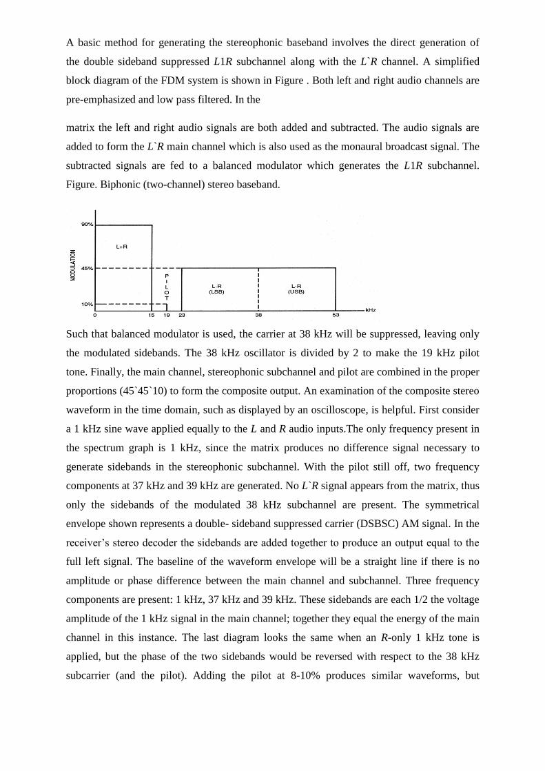
A basic method for generating the stereophonic baseband involves the direct generation of
the double sideband suppressed L1R subchannel along with the L`R channel. A simplified
block diagram of the FDM system is shown in Figure . Both left and right audio channels are
pre-emphasized and low pass filtered. In the
matrix the left and right audio signals are both added and subtracted. The audio signals are
added to form the L`R main channel which is also used as the monaural broadcast signal. The
subtracted signals are fed to a balanced modulator which generates the L1R subchannel.
Figure. Biphonic (two-channel) stereo baseband.
Such that balanced modulator is used, the carrier at 38 kHz will be suppressed, leaving only
the modulated sidebands. The 38 kHz oscillator is divided by 2 to make the 19 kHz pilot
tone. Finally, the main channel, stereophonic subchannel and pilot are combined in the proper
proportions (45`45`10) to form the composite output. An examination of the composite stereo
waveform in the time domain, such as displayed by an oscilloscope, is helpful. First consider
a 1 kHz sine wave applied equally to the L and R audio inputs.The only frequency present in
the spectrum graph is 1 kHz, since the matrix produces no difference signal necessary to
generate sidebands in the stereophonic subchannel. With the pilot still off, two frequency
components at 37 kHz and 39 kHz are generated. No L`R signal appears from the matrix, thus
only the sidebands of the modulated 38 kHz subchannel are present. The symmetrical
envelope shown represents a double- sideband suppressed carrier (DSBSC) AM signal. In the
receiver‘s stereo decoder the sidebands are added together to produce an output equal to the
full left signal. The baseline of the waveform envelope will be a straight line if there is no
amplitude or phase difference between the main channel and subchannel. Three frequency
components are present: 1 kHz, 37 kHz and 39 kHz. These sidebands are each 1/2 the voltage
amplitude of the 1 kHz signal in the main channel; together they equal the energy of the main
channel in this instance. The last diagram looks the same when an R-only 1 kHz tone is
applied, but the phase of the two sidebands would be reversed with respect to the 38 kHz
subcarrier (and the pilot). Adding the pilot at 8-10% produces similar waveforms, but
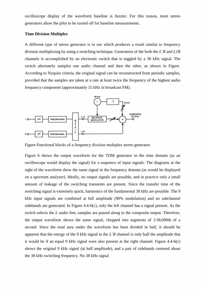
oscilloscope display of the waveform baseline is fuzzier. For this reason, most stereo
generators allow the pilot to be turned off for baseline measurements.
Time Division Multiplex
A different type of stereo generator is in use which produces a result similar to frequency
division multiplexing by using a switching technique. Generation of the both the L`R and L1R
channels is accomplished by an electronic switch that is toggled by a 38 kHz signal. The
switch alternately samples one audio channel and then the other, as shown in Figure.
According to Nyquist criteria, the original signal can be reconstructed from periodic samples,
provided that the samples are taken at a rate at least twice the frequency of the highest audio
frequency component (approximately 15 kHz in broadcast FM).
Figure Functional blocks of a frequency division multiplex stereo generator.
Figure 6 shows the output waveform for the TDM generator in the time domain (as an
oscilloscope would display the signal) for a sequence of input signals. The diagrams at the
right of the waveform show the same signal in the frequency domain (as would be displayed
on a spectrum analyzer). Ideally, no output signals are possible, and in practice only a small
amount of leakage of the switching transients are present. Since the transfer time of the
switching signal is extremely quick, harmonics of the fundamental 38 kHz are possible. The 9
kHz input signals are combined at full amplitude (90% modulation) and no subchannel
sidebands are generated. In Figure 4.4-6(c), only the left channel has a signal present. As the
switch selects the L audio line, samples are passed along to the composite output. Therefore,
the output waveform shows the same signal, chopped into segments of 1/38,000th of a
second. Since the total area under the waveform has been divided in half, it should be
apparent that the energy of the 9 kHz signal in the L`R channel is only half the amplitude that
it would be if an equal 9 kHz signal were also present at the right channel. Figure 4.4-6(c)
shows the original 9 kHz signal (at half amplitude), and a pair of sidebands centered about
the 38 kHz switching frequency. No 38 kHz signal
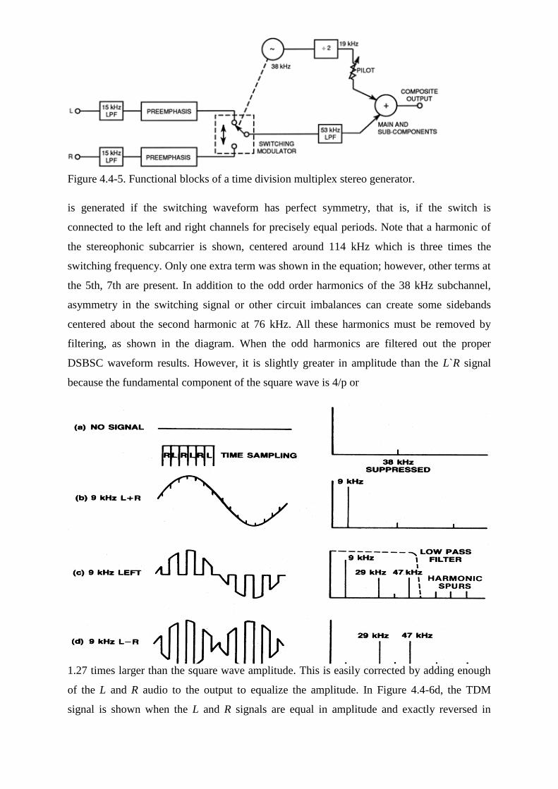
Figure 4.4-5. Functional blocks of a time division multiplex stereo generator.
is generated if the switching waveform has perfect symmetry, that is, if the switch is
connected to the left and right channels for precisely equal periods. Note that a harmonic of
the stereophonic subcarrier is shown, centered around 114 kHz which is three times the
switching frequency. Only one extra term was shown in the equation; however, other terms at
the 5th, 7th are present. In addition to the odd order harmonics of the 38 kHz subchannel,
asymmetry in the switching signal or other circuit imbalances can create some sidebands
centered about the second harmonic at 76 kHz. All these harmonics must be removed by
filtering, as shown in the diagram. When the odd harmonics are filtered out the proper
DSBSC waveform results. However, it is slightly greater in amplitude than the L`R signal
because the fundamental component of the square wave is 4/p or
1.27 times larger than the square wave amplitude. This is easily corrected by adding enough
of the L and R audio to the output to equalize the amplitude. In Figure 4.4-6d, the TDM
signal is shown when the L and R signals are equal in amplitude and exactly reversed in
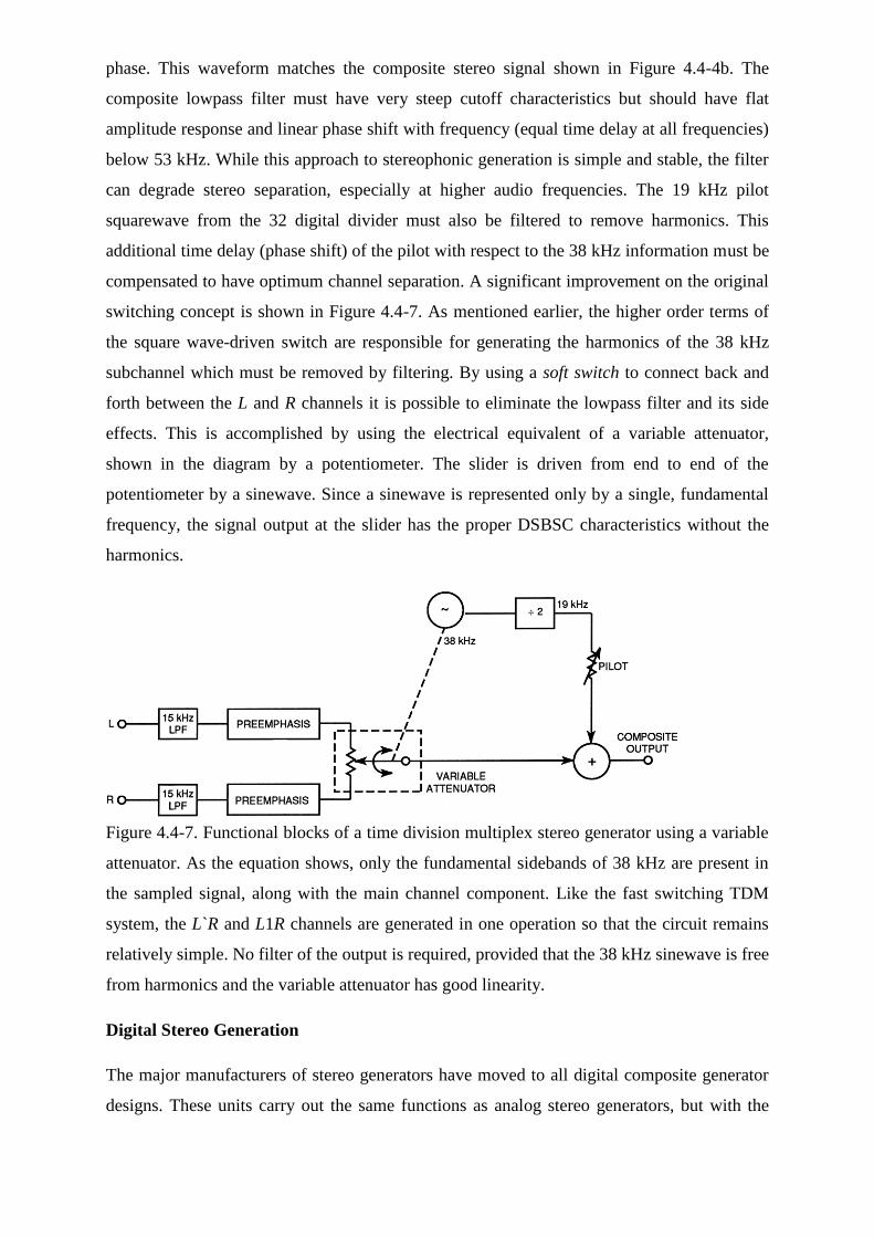
phase. This waveform matches the composite stereo signal shown in Figure 4.4-4b. The
composite lowpass filter must have very steep cutoff characteristics but should have flat
amplitude response and linear phase shift with frequency (equal time delay at all frequencies)
below 53 kHz. While this approach to stereophonic generation is simple and stable, the filter
can degrade stereo separation, especially at higher audio frequencies. The 19 kHz pilot
squarewave from the 32 digital divider must also be filtered to remove harmonics. This
additional time delay (phase shift) of the pilot with respect to the 38 kHz information must be
compensated to have optimum channel separation. A significant improvement on the original
switching concept is shown in Figure 4.4-7. As mentioned earlier, the higher order terms of
the square wave-driven switch are responsible for generating the harmonics of the 38 kHz
subchannel which must be removed by filtering. By using a soft switch to connect back and
forth between the L and R channels it is possible to eliminate the lowpass filter and its side
effects. This is accomplished by using the electrical equivalent of a variable attenuator,
shown in the diagram by a potentiometer. The slider is driven from end to end of the
potentiometer by a sinewave. Since a sinewave is represented only by a single, fundamental
frequency, the signal output at the slider has the proper DSBSC characteristics without the
harmonics.
Figure 4.4-7. Functional blocks of a time division multiplex stereo generator using a variable
attenuator. As the equation shows, only the fundamental sidebands of 38 kHz are present in
the sampled signal, along with the main channel component. Like the fast switching TDM
system, the L`R and L1R channels are generated in one operation so that the circuit remains
relatively simple. No filter of the output is required, provided that the 38 kHz sinewave is free
from harmonics and the variable attenuator has good linearity.
Digital Stereo Generation
The major manufacturers of stereo generators have moved to all digital composite generator
designs. These units carry out the same functions as analog stereo generators, but with the
flexibility and consistency commonly expected of digital audio systems. Some generators
also perform all the audio compression and peak limiting functions in the digital domain.
This chapter is confined to a discussion of digital stereo generation techniques. Digital
implementation is made easier if the output sampling rate is a binary multiple of either of the
two steady state vectors in the composite signal: the stereo pilot or the L1R subcarrier. For
example, an oversampling rate of 304 kHz is sometimes employed (this is eight times the
subcarrier frequency, and 16 times the pilot). The input sampling rate is also an important
consideration. The reader will note that switching type stereo generators, discussed earlier,
operate at only 38 kHz. While higher rates do not yield any additional improvement in
fidelity, it is desirable to use a higher rate throughout the generator system. While Digital
Compact Discs© are fixed at 16-bit quantization precision, most digital stereo generator
designs use more bits per sample. This is because analog-to-digital (A/D) conversion devices
do not perform to the theoretical limits of 16 bits, and because the mathematical precision of
the processing architecture can produce rounding errors that contribute noise and distortion to
the processed signal. Eighteen to 24 bit data paths are generally chosen. Analog audio for
each channel is passed through an anti-aliasing lowpass filter and is then A/D converted into
digital data streams. At this point, generators with audio processing carry out algorithms that
gain-control, pre-emphasize, limit and filter the digital audio stream. The dynamic effects are
very similar to analog processors even though the treatment is entirely digital. The processed
L and R signals are then numerically matrixed using simple addition into L`R and L1R
channels. The digitized 38 kHz sinewave is derived from a look up table and digitally
multiplied by the L1R channel to produce the 38 kHz DSBSC. The 19 kHz pilot is generated
by another look up table that is locked via software control so that the phasing relative to the
38 kHz subchannel is perfect. The pilot and 38 kHz subchannel are finally summed and
applied to a digital-to-analog (D/A) converter to form the complete composite stereo signal.
Some manufacturers provide a separate digital output port for digital FM exciters.
QUESTIONS
1. List the important steps and considerations in recording and editing digital audio?
2. Discuss the audio file formats used in multimedia projects and how they are used?
3. Discuss the various factors that apply to the use of images in multimedia?
4. Describe the capabilities and limitations of bitmap images?
5. Describe the capabilities and limitations of vector images?
6. Define various aspects of 3-D modeling?
7. Describe the use of colors and palettes in multimedia? Discuss the various file types used
in multimedia?
8. Describe animation and describe how it can be used in multimedia?
9. Discuss the origin of cel animation and define the words that originate from this technique?
Define the capabilities of computer animation and the mathematical techniques that differ
from traditional cel animation?
10. Discuss the important considerations in using digital video in multimedia? Describe the
basics of video recording and how they relate to multimedia production?
11. List important considerations in converting from digital video to television? Also list the
important considerations in shooting and editing video for use in multimedia?
CHAPTER 4
MPEG AUDIO
MPEG/Audio Compression
The Motion Picture Experts Group (MPEG) audio compression algorithm is an International
Organization for Standardization (ISO) standard for high fidelity audio compression. It is one
part of a three part compression standard. With the other two parts, video and systems, the
composite standard addresses the compression of synchronized video and audio at a total bit
rate of roughly 1.5 megabits per second. Like _-law and ADPCM, the MPEG/audio
compression is lossy; however, the MPEG algorithm can achieve transparent, perceptually
lossless compression. The MPEG/audio committee conducted extensive subjective listening
tests during the development of the standard. The tests showed that even with a 6-to-1
compression ratio (stereo, 16-bit-persample audio sampled at 48 kHz compressed to 256
kilobits per second) and under optimal listening conditions, expert listeners were unable to
distinguish between coded and original audio clips with statistical significance. Furthermore,
these clips were specially chosen because they are difficult to compress. Grewin and Ryden
give the details of the setup, procedures, and results of these tests.[9] The high performance
of this compression algorithm is due to the exploitation of auditory masking. This masking is
a perceptual weakness of the ear that occurs whenever the presence of a strong audio signal
makes a spectral neighbourhood of weaker audio signals imperceptible. This noisemasking
phenomenon has been observed and corroborated through a variety of psychoacoustic
experiments.[10] Empirical results also show that the ear has a limited frequency selectivity
that varies in acuity from less than 100 Hz for the lowest audible frequencies to more than 4
kHz for the highest. Thus the audible spectrum can be partitioned into critical bands that
reflect the resolving power of the ear as a function of frequency. Because of the ear‘s limited
frequency resolving power, the threshold for noise masking at any given frequency is solely
dependent on the signal activity within a critical band of that frequency. Figure 5 illustrates
this property. For audio compression, this property can be capitalized by transforming the
audio signal into the frequency domain, then dividing the resulting spectrum into subbands
that approximate critical bands, and finally quantizing each subband according to the
audibility of quantization noise within that band. For optimal compression, each band should
be quantized with no more levels than necessary to make the quantization noise inaudible.
The following sections present a more detailed description of the MPEG/audio algorithm.
MPEG/Audio Encoding and Decoding
Figure 6 shows block diagrams of the MPEG/audio encoder and decoder.[11,12] In this high-
level representation, encoding closely parallels the process described above. The input audio
stream passes through a filter bank that divides the input into multiple subbands. The input
audio stream simultaneously passes through a psychoacoustic model that determines the
signal-to-mask ratio of each subband. The bit or noise allocation block uses the signal-to-
mask ratios to decide how to apportion the total number of code bits available for the
quantization of the subband signals to minimize the audibility of the quantization noise.
Finally, the last block takes the representation of the quantized audio samples and formats the
data into a decodable bit stream. The decoder simply reverses the formatting, then
reconstructs the quantized subband values, and finally transforms the set of subband values
into a time-domain audio signal. As specified by the MPEG requirements, ancillary data not
necessarily related to the audio stream can be fitted within the coded bit stream. The
MPEG/audio standard has three distinct layers for compression. Layer I forms the most basic
algorithm, and Layers II and III are enhancements that use some elements found in Layer I.
Each successive layer improves the compression performance but at the cost of greater
encoder and decoder complexity. Layer I. The Layer I algorithm uses the basic filter bank
found in all layers. This filter bank divides the audio signal into 32 constant-width frequency
bands. The filters are relatively simple and provide good time resolution with reasonable
frequency resolution relative to the perceptual properties of the human ear. The design is a
compromise with three notable concessions. First, the 32 constantwidth bands do not
accurately reflect the ear‘s critical bands. Figure 7 illustrates this discrepancy. The bandwidth
is too wide for the lower frequencies so the number of quantizer bits cannot be specifically
tuned for the noise sensitivity within each critical band. Instead, the included critical band
with the greatest noise sensitivity dictates the number of quantization bits required for the
entire filter band. Second, the filter bank and its inverse are not lossless transformations.
Even without quantization, the inverse transformation would not perfectly recover the
original input signal. Fortunately, the error introduced by the filter bank is small and
inaudible. Finally, adjacent filter bands have a significant frequency overlap. A signal at a
single frequency can affect two adjacent filter bank outputs.
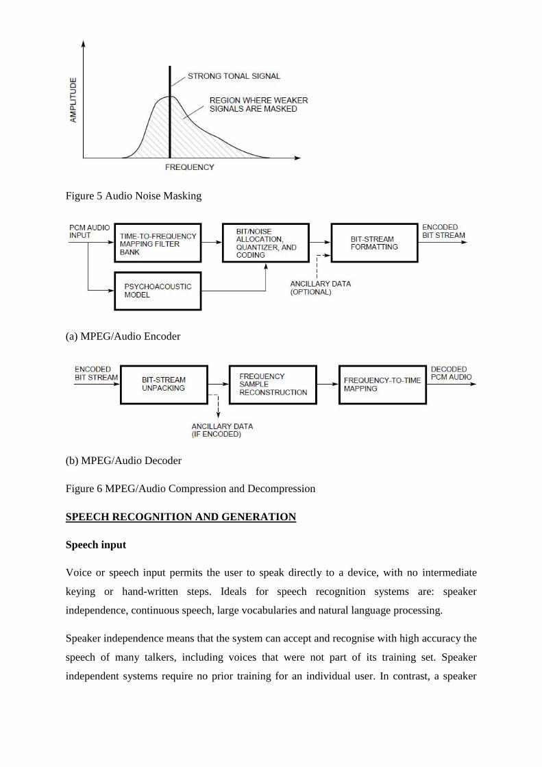
Figure 5 Audio Noise Masking
(a) MPEG/Audio Encoder
(b) MPEG/Audio Decoder
Figure 6 MPEG/Audio Compression and Decompression
SPEECH RECOGNITION AND GENERATION
Speech input
Voice or speech input permits the user to speak directly to a device, with no intermediate
keying or hand-written steps. Ideals for speech recognition systems are: speaker
independence, continuous speech, large vocabularies and natural language processing.
Speaker independence means that the system can accept and recognise with high accuracy the
speech of many talkers, including voices that were not part of its training set. Speaker
independent systems require no prior training for an individual user. In contrast, a speaker
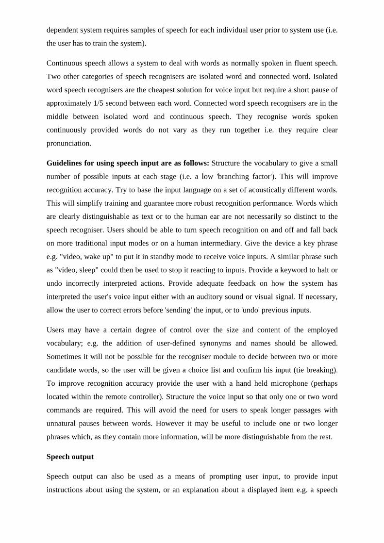
dependent system requires samples of speech for each individual user prior to system use (i.e.
the user has to train the system).
Continuous speech allows a system to deal with words as normally spoken in fluent speech.
Two other categories of speech recognisers are isolated word and connected word. Isolated
word speech recognisers are the cheapest solution for voice input but require a short pause of
approximately 1/5 second between each word. Connected word speech recognisers are in the
middle between isolated word and continuous speech. They recognise words spoken
continuously provided words do not vary as they run together i.e. they require clear
pronunciation.
Guidelines for using speech input are as follows: Structure the vocabulary to give a small
number of possible inputs at each stage (i.e. a low 'branching factor'). This will improve
recognition accuracy. Try to base the input language on a set of acoustically different words.
This will simplify training and guarantee more robust recognition performance. Words which
are clearly distinguishable as text or to the human ear are not necessarily so distinct to the
speech recogniser. Users should be able to turn speech recognition on and off and fall back
on more traditional input modes or on a human intermediary. Give the device a key phrase
e.g. "video, wake up" to put it in standby mode to receive voice inputs. A similar phrase such
as "video, sleep" could then be used to stop it reacting to inputs. Provide a keyword to halt or
undo incorrectly interpreted actions. Provide adequate feedback on how the system has
interpreted the user's voice input either with an auditory sound or visual signal. If necessary,
allow the user to correct errors before 'sending' the input, or to 'undo' previous inputs.
Users may have a certain degree of control over the size and content of the employed
vocabulary; e.g. the addition of user-defined synonyms and names should be allowed.
Sometimes it will not be possible for the recogniser module to decide between two or more
candidate words, so the user will be given a choice list and confirm his input (tie breaking).
To improve recognition accuracy provide the user with a hand held microphone (perhaps
located within the remote controller). Structure the voice input so that only one or two word
commands are required. This will avoid the need for users to speak longer passages with
unnatural pauses between words. However it may be useful to include one or two longer
phrases which, as they contain more information, will be more distinguishable from the rest.
Speech output
Speech output can also be used as a means of prompting user input, to provide input
instructions about using the system, or an explanation about a displayed item e.g. a speech
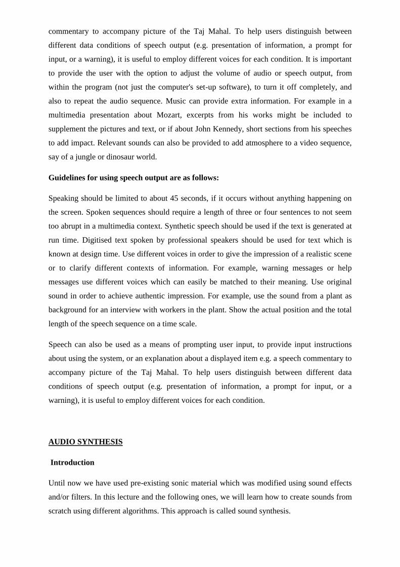
commentary to accompany picture of the Taj Mahal. To help users distinguish between
different data conditions of speech output (e.g. presentation of information, a prompt for
input, or a warning), it is useful to employ different voices for each condition. It is important
to provide the user with the option to adjust the volume of audio or speech output, from
within the program (not just the computer's set-up software), to turn it off completely, and
also to repeat the audio sequence. Music can provide extra information. For example in a
multimedia presentation about Mozart, excerpts from his works might be included to
supplement the pictures and text, or if about John Kennedy, short sections from his speeches
to add impact. Relevant sounds can also be provided to add atmosphere to a video sequence,
say of a jungle or dinosaur world.
Guidelines for using speech output are as follows:
Speaking should be limited to about 45 seconds, if it occurs without anything happening on
the screen. Spoken sequences should require a length of three or four sentences to not seem
too abrupt in a multimedia context. Synthetic speech should be used if the text is generated at
run time. Digitised text spoken by professional speakers should be used for text which is
known at design time. Use different voices in order to give the impression of a realistic scene
or to clarify different contexts of information. For example, warning messages or help
messages use different voices which can easily be matched to their meaning. Use original
sound in order to achieve authentic impression. For example, use the sound from a plant as
background for an interview with workers in the plant. Show the actual position and the total
length of the speech sequence on a time scale.
Speech can also be used as a means of prompting user input, to provide input instructions
about using the system, or an explanation about a displayed item e.g. a speech commentary to
accompany picture of the Taj Mahal. To help users distinguish between different data
conditions of speech output (e.g. presentation of information, a prompt for input, or a
warning), it is useful to employ different voices for each condition.
AUDIO SYNTHESIS
Introduction
Until now we have used pre-existing sonic material which was modified using sound effects
and/or filters. In this lecture and the following ones, we will learn how to create sounds from
scratch using different algorithms. This approach is called sound synthesis.
In this lecture, we will learn about three synthesis techniques:
1. wavetable synthesis
2. additive synthesis
3. subtractive synthesis.
In order to synthesize sounds two main approaches can be followed:
1. Analysis of real sounds to acquire parameters (frequency, amplitude...).
2. Adjusting the parameters by listening.
Usually automatic analysis of real sounds is a complex process, especially when the task is to
analyze complex sounds such as everyday sounds.
Therefore, a combination of automatic analysis and adjustment by listening is usually
adopted by sound designers.
2 Wavetable synthesis
Wavetable synthesis is probably the main music synthesis method used in multimedia home
computers, and the oldest technique for creating sounds with a computer.
In wavetable synthesis, a single period of a periodic waveform is stored in a circular buffer.
Wavetable synthesis is used in digital musical instruments (synthesizers) to produce natural
sounds. The sound of a existing instrument is sampled and stored inside a wavetable. The
wavetable is a collection of these small samples. By repeatedly playing samples from this
table in a loop the original sound is imitated.
In its simplest form wavetable synthesis is simply playing back a sampled sound. Several
additional features are added, primarily to save memory. One addition is the inclusion of
looping points, so that the sound can be continuously played without storing unnecessary
data. Moreover, sounds are played at different frequencies. This is accomplished by stepping
through the table at different steps.
The simplest example of wavetable synthesis is a sinewave which can be easily produced in
Max/MSP by using the object cycle~.
This object uses wavetable synthesis, since it reads through a list of 512 values at a specified
rate, looping back to the beginning of the list when the end is reached.
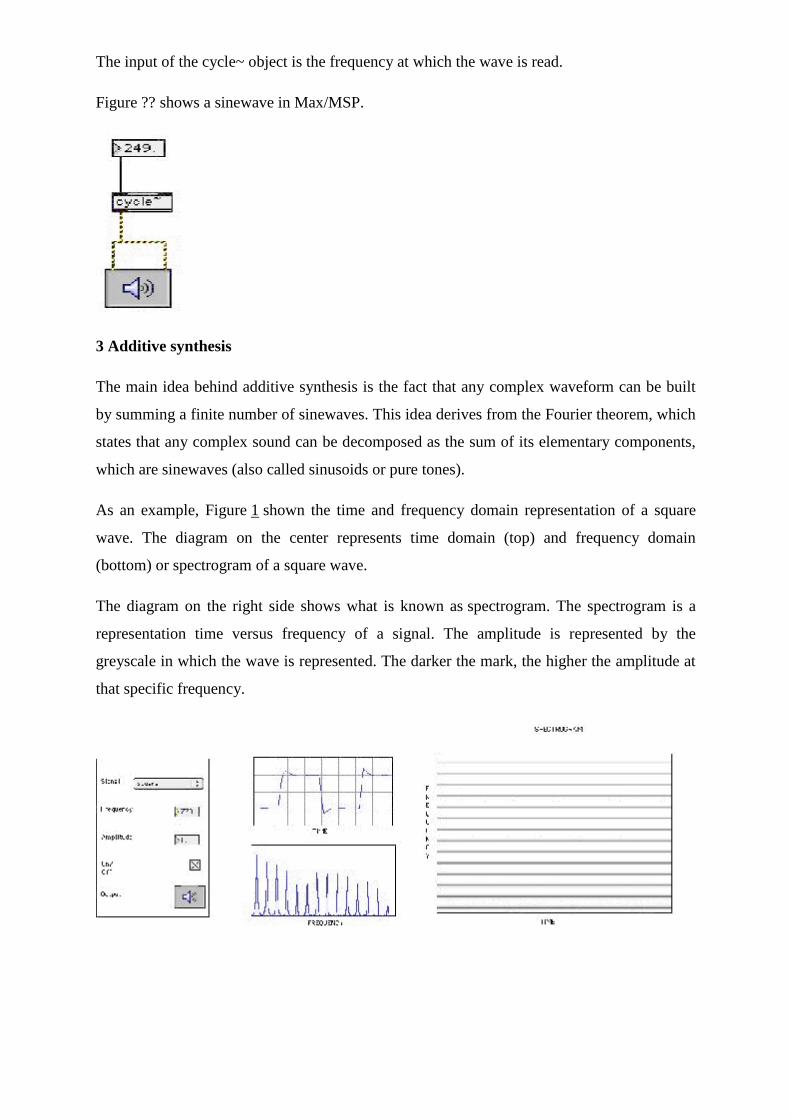
The input of the cycle~ object is the frequency at which the wave is read.
Figure ?? shows a sinewave in Max/MSP.
3 Additive synthesis
The main idea behind additive synthesis is the fact that any complex waveform can be built
by summing a finite number of sinewaves. This idea derives from the Fourier theorem, which
states that any complex sound can be decomposed as the sum of its elementary components,
which are sinewaves (also called sinusoids or pure tones).
As an example, Figure 1 shown the time and frequency domain representation of a square
wave. The diagram on the center represents time domain (top) and frequency domain
(bottom) or spectrogram of a square wave.
The diagram on the right side shows what is known as spectrogram. The spectrogram is a
representation time versus frequency of a signal. The amplitude is represented by the
greyscale in which the wave is represented. The darker the mark, the higher the amplitude at
that specific frequency.
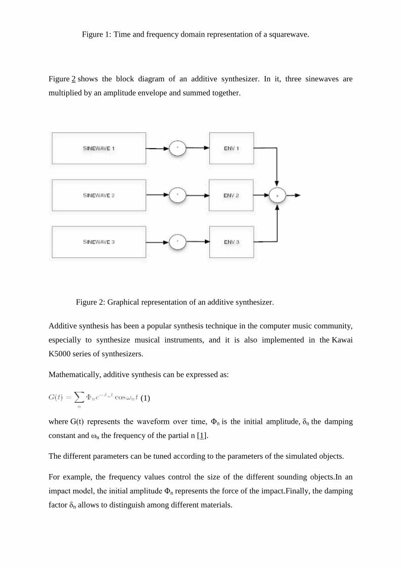
Figure 1: Time and frequency domain representation of a squarewave.
Figure 2 shows the block diagram of an additive synthesizer. In it, three sinewaves are
multiplied by an amplitude envelope and summed together.
Figure 2: Graphical representation of an additive synthesizer.
Additive synthesis has been a popular synthesis technique in the computer music community,
especially to synthesize musical instruments, and it is also implemented in the Kawai
K5000 series of synthesizers.
Mathematically, additive synthesis can be expressed as:
(1)
where G(t) represents the waveform over time, Φn is the initial amplitude, δn the damping
constant and ωn the frequency of the partial n [1].
The different parameters can be tuned according to the parameters of the simulated objects.
For example, the frequency values control the size of the different sounding objects.In an
impact model, the initial amplitude Φn represents the force of the impact.Finally, the damping
factor δn allows to distinguish among different materials.
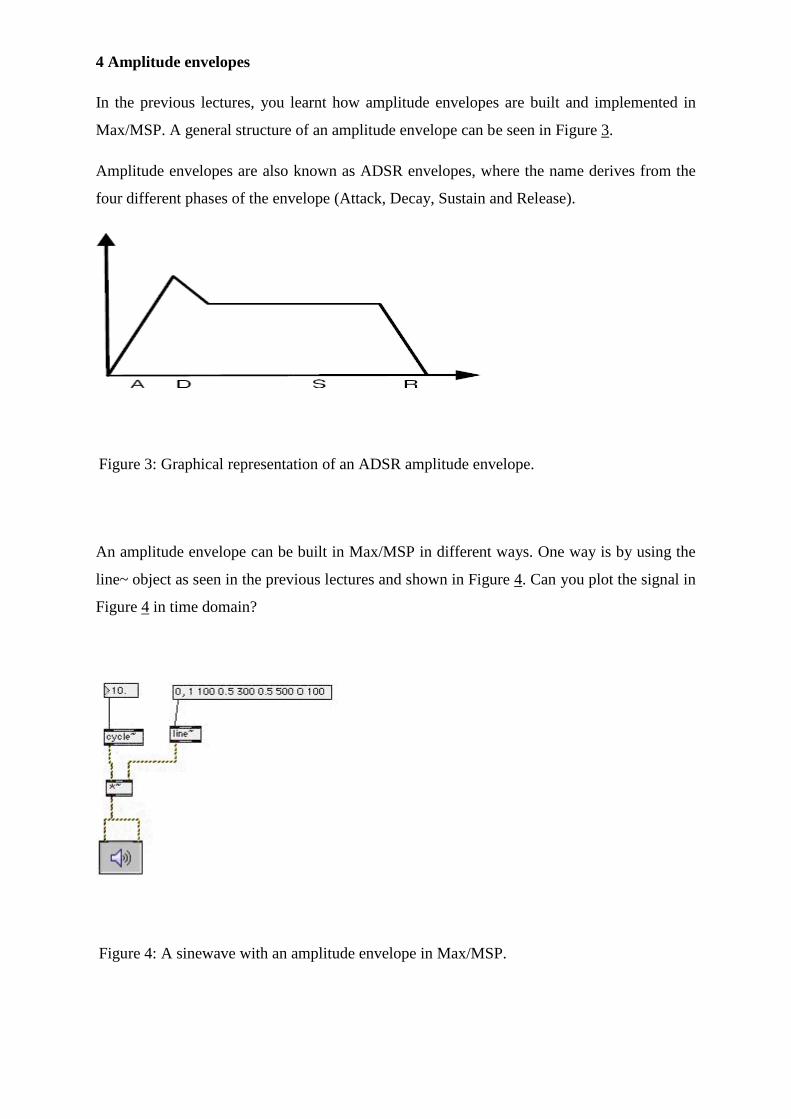
4 Amplitude envelopes
In the previous lectures, you learnt how amplitude envelopes are built and implemented in
Max/MSP. A general structure of an amplitude envelope can be seen in Figure 3.
Amplitude envelopes are also known as ADSR envelopes, where the name derives from the
four different phases of the envelope (Attack, Decay, Sustain and Release).
Figure 3: Graphical representation of an ADSR amplitude envelope.
An amplitude envelope can be built in Max/MSP in different ways. One way is by using the
line~ object as seen in the previous lectures and shown in Figure 4. Can you plot the signal in
Figure 4 in time domain?
Figure 4: A sinewave with an amplitude envelope in Max/MSP.
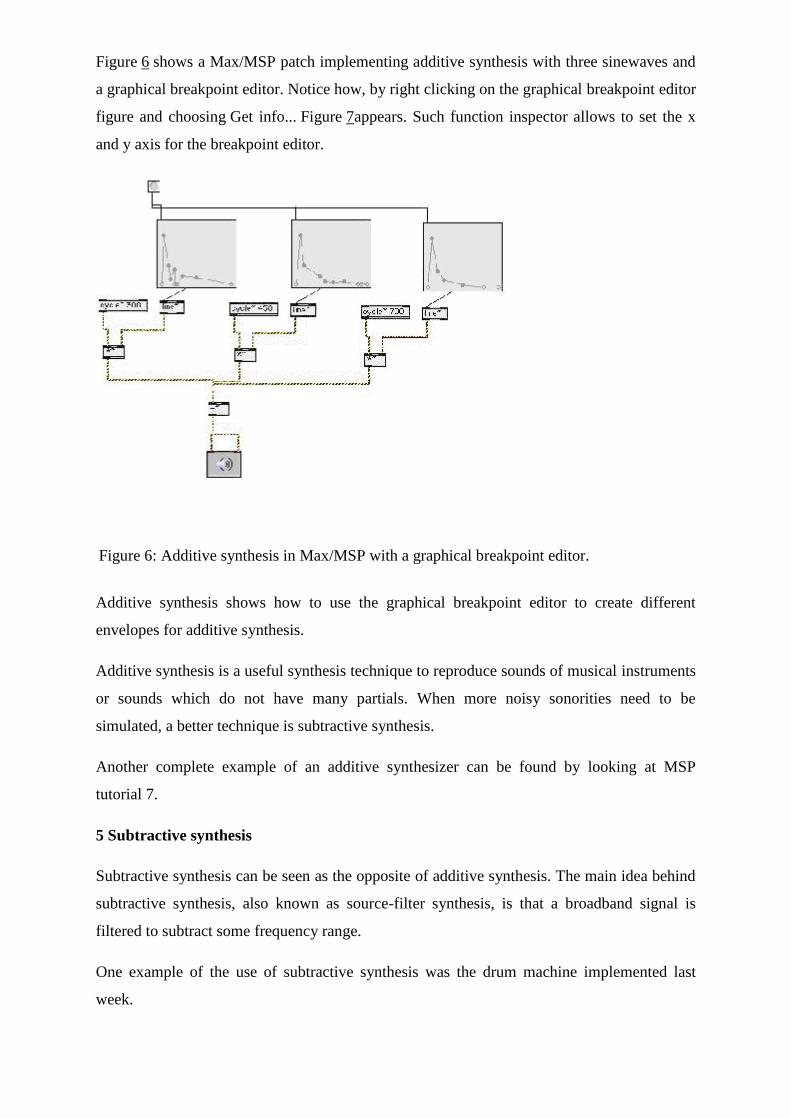
Figure 6 shows a Max/MSP patch implementing additive synthesis with three sinewaves and
a graphical breakpoint editor. Notice how, by right clicking on the graphical breakpoint editor
figure and choosing Get info... Figure 7appears. Such function inspector allows to set the x
and y axis for the breakpoint editor.
Figure 6: Additive synthesis in Max/MSP with a graphical breakpoint editor.
Additive synthesis shows how to use the graphical breakpoint editor to create different
envelopes for additive synthesis.
Additive synthesis is a useful synthesis technique to reproduce sounds of musical instruments
or sounds which do not have many partials. When more noisy sonorities need to be
simulated, a better technique is subtractive synthesis.
Another complete example of an additive synthesizer can be found by looking at MSP
tutorial 7.
5 Subtractive synthesis
Subtractive synthesis can be seen as the opposite of additive synthesis. The main idea behind
subtractive synthesis, also known as source-filter synthesis, is that a broadband signal is
filtered to subtract some frequency range.
One example of the use of subtractive synthesis was the drum machine implemented last
week.
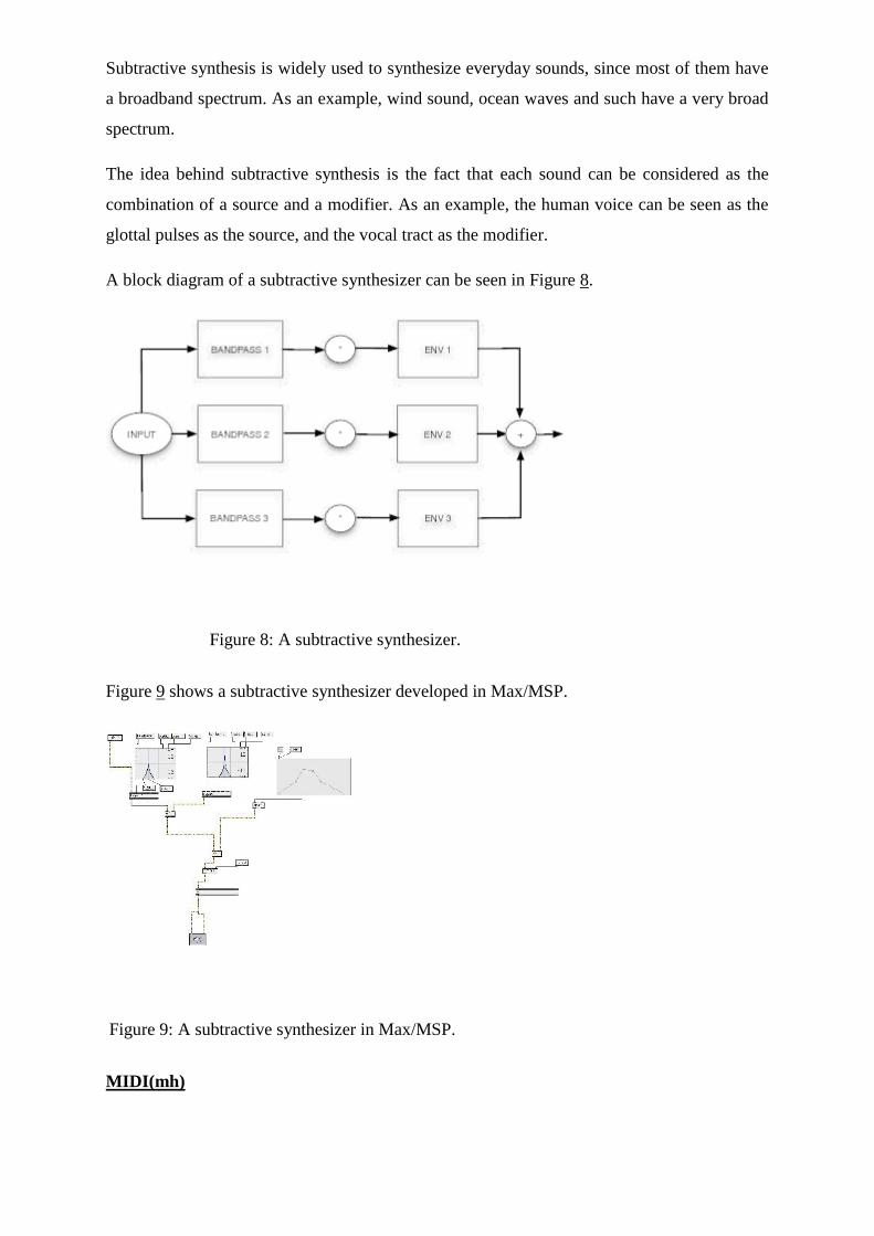
Subtractive synthesis is widely used to synthesize everyday sounds, since most of them have
a broadband spectrum. As an example, wind sound, ocean waves and such have a very broad
spectrum.
The idea behind subtractive synthesis is the fact that each sound can be considered as the
combination of a source and a modifier. As an example, the human voice can be seen as the
glottal pulses as the source, and the vocal tract as the modifier.
A block diagram of a subtractive synthesizer can be seen in Figure 8.
Figure 8: A subtractive synthesizer.
Figure 9 shows a subtractive synthesizer developed in Max/MSP.
Figure 9: A subtractive synthesizer in Max/MSP.
MIDI(mh)
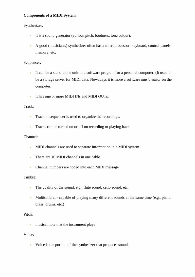
Components of a MIDI System
Synthesizer:
It is a sound generator (various pitch, loudness, tone colour).
A good (musician's) synthesizer often has a microprocessor, keyboard, control panels,
memory, etc.
Sequencer:
It can be a stand-alone unit or a software program for a personal computer. (It used to
be a storage server for MIDI data. Nowadays it is more a software music editor on the
computer.
It has one or more MIDI INs and MIDI OUTs.
Track:
Track in sequencer is used to organize the recordings.
Tracks can be turned on or off on recording or playing back.
Channel:
MIDI channels are used to separate information in a MIDI system.
There are 16 MIDI channels in one cable.
Channel numbers are coded into each MIDI message.
Timbre:
The quality of the sound, e.g., flute sound, cello sound, etc.
Multitimbral - capable of playing many different sounds at the same time (e.g., piano,
brass, drums, etc.)
Pitch:
musical note that the instrument plays
Voice:
Voice is the portion of the synthesizer that produces sound.
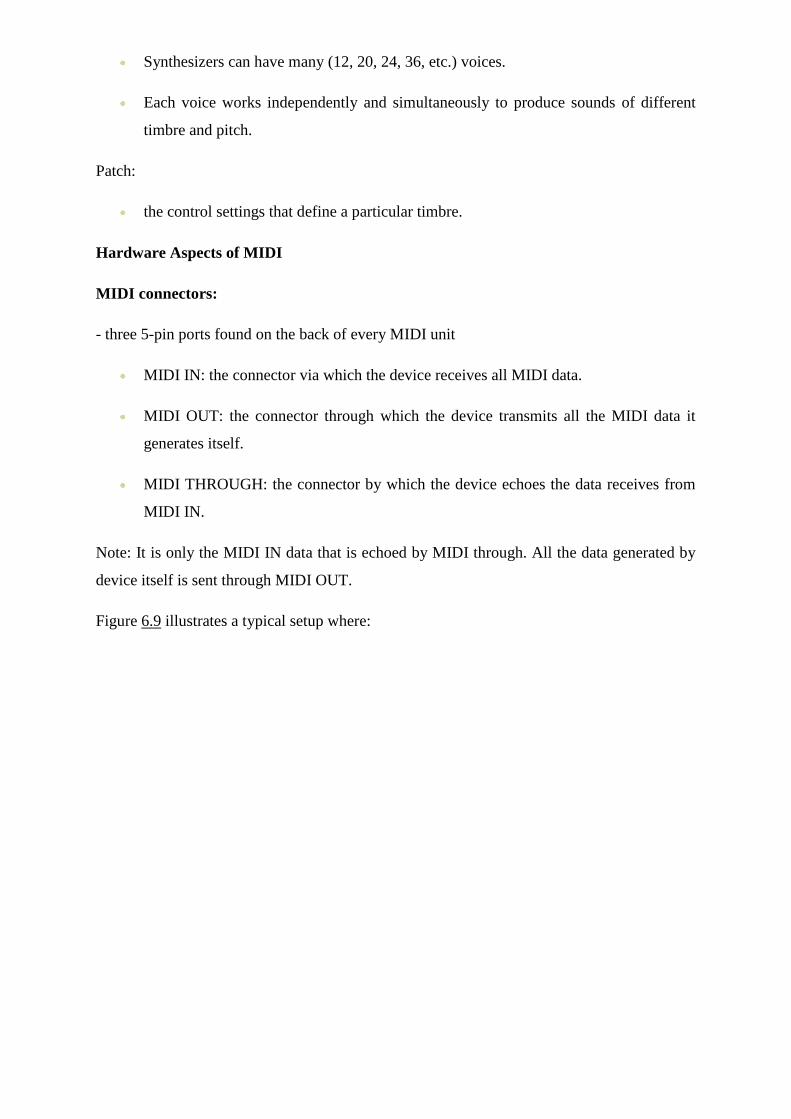
Synthesizers can have many (12, 20, 24, 36, etc.) voices.
Each voice works independently and simultaneously to produce sounds of different
timbre and pitch.
Patch:
the control settings that define a particular timbre.
Hardware Aspects of MIDI
MIDI connectors:
- three 5-pin ports found on the back of every MIDI unit
MIDI IN: the connector via which the device receives all MIDI data.
MIDI OUT: the connector through which the device transmits all the MIDI data it
generates itself.
MIDI THROUGH: the connector by which the device echoes the data receives from
MIDI IN.
Note: It is only the MIDI IN data that is echoed by MIDI through. All the data generated by
device itself is sent through MIDI OUT.
Figure 6.9 illustrates a typical setup where:
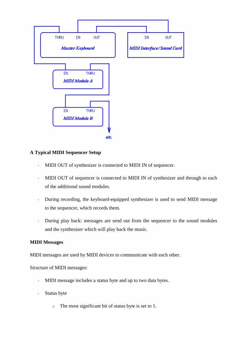
A Typical MIDI Sequencer Setup
MIDI OUT of synthesizer is connected to MIDI IN of sequencer.
MIDI OUT of sequencer is connected to MIDI IN of synthesizer and through to each
of the additional sound modules.
During recording, the keyboard-equipped synthesizer is used to send MIDI message
to the sequencer, which records them.
During play back: messages are send out from the sequencer to the sound modules
and the synthesizer which will play back the music.
MIDI Messages
MIDI messages are used by MIDI devices to communicate with each other.
Structure of MIDI messages:
MIDI message includes a status byte and up to two data bytes.
Status byte
o The most significant bit of status byte is set to 1.
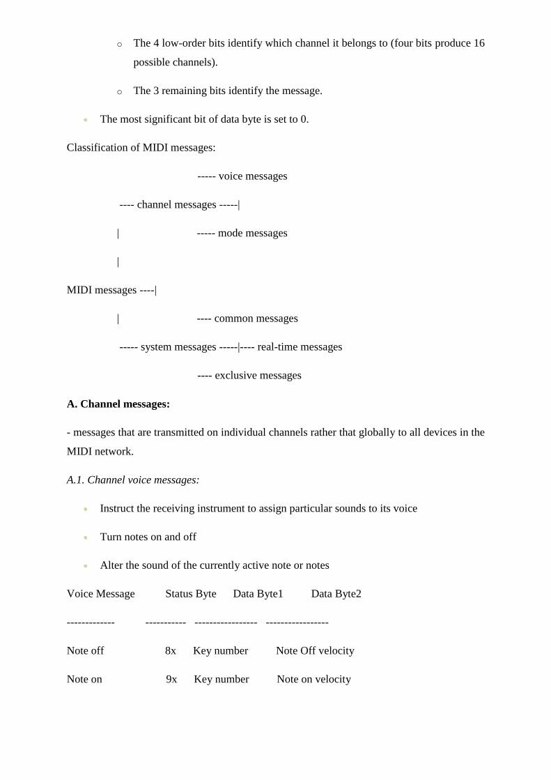
o The 4 low-order bits identify which channel it belongs to (four bits produce 16
possible channels).
o The 3 remaining bits identify the message.
The most significant bit of data byte is set to 0.
Classification of MIDI messages:
----- voice messages
---- channel messages -----|
| ----- mode messages
|
MIDI messages ----|
| ---- common messages
----- system messages -----|---- real-time messages
---- exclusive messages
A. Channel messages:
- messages that are transmitted on individual channels rather that globally to all devices in the
MIDI network.
A.1. Channel voice messages:
Instruct the receiving instrument to assign particular sounds to its voice
Turn notes on and off
Alter the sound of the currently active note or notes
Voice Message Status Byte Data Byte1 Data Byte2
------------- ----------- ----------------- -----------------
Note off 8x Key number Note Off velocity
Note on 9x Key number Note on velocity
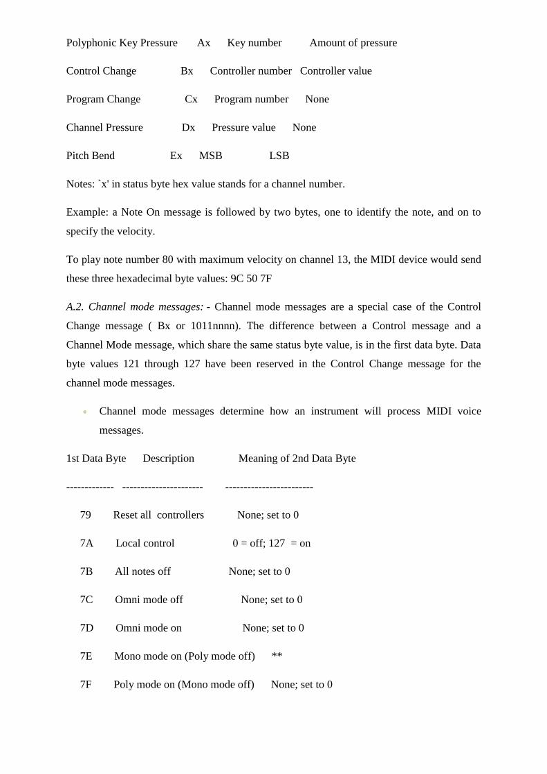
Polyphonic Key Pressure Ax Key number Amount of pressure
Control Change Bx Controller number Controller value
Program Change Cx Program number None
Channel Pressure Dx Pressure value None
Pitch Bend Ex MSB LSB
Notes: `x' in status byte hex value stands for a channel number.
Example: a Note On message is followed by two bytes, one to identify the note, and on to
specify the velocity.
To play note number 80 with maximum velocity on channel 13, the MIDI device would send
these three hexadecimal byte values: 9C 50 7F
A.2. Channel mode messages: - Channel mode messages are a special case of the Control
Change message ( Bx or 1011nnnn). The difference between a Control message and a
Channel Mode message, which share the same status byte value, is in the first data byte. Data
byte values 121 through 127 have been reserved in the Control Change message for the
channel mode messages.
Channel mode messages determine how an instrument will process MIDI voice
messages.
1st Data Byte Description Meaning of 2nd Data Byte
------------- ---------------------- ------------------------
79 Reset all controllers None; set to 0
7A Local control 0 = off; 127 = on
7B All notes off None; set to 0
7C Omni mode off None; set to 0
7D Omni mode on None; set to 0
7E Mono mode on (Poly mode off) **
7F Poly mode on (Mono mode off) None; set to 0
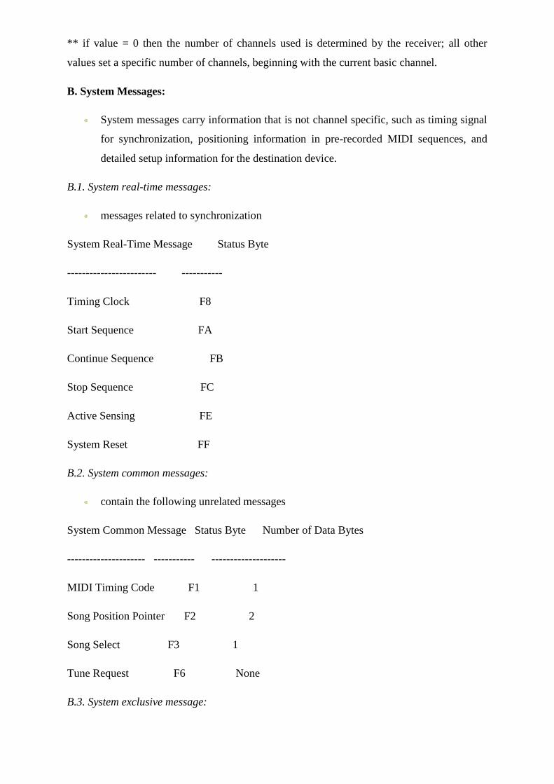
** if value = 0 then the number of channels used is determined by the receiver; all other
values set a specific number of channels, beginning with the current basic channel.
B. System Messages:
System messages carry information that is not channel specific, such as timing signal
for synchronization, positioning information in pre-recorded MIDI sequences, and
detailed setup information for the destination device.
B.1. System real-time messages:
messages related to synchronization
System Real-Time Message Status Byte
------------------------ -----------
Timing Clock F8
Start Sequence FA
Continue Sequence FB
Stop Sequence FC
Active Sensing FE
System Reset FF
B.2. System common messages:
contain the following unrelated messages
System Common Message Status Byte Number of Data Bytes
--------------------- ----------- --------------------
MIDI Timing Code F1 1
Song Position Pointer F2 2
Song Select F3 1
Tune Request F6 None
B.3. System exclusive message:
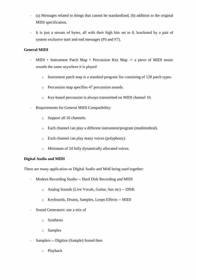
(a) Messages related to things that cannot be standardized, (b) addition to the original
MIDI specification.
It is just a stream of bytes, all with their high bits set to 0, bracketed by a pair of
system exclusive start and end messages (F0 and F7).
General MIDI
MIDI + Instrument Patch Map + Percussion Key Map -> a piece of MIDI music
sounds the same anywhere it is played
o Instrument patch map is a standard program list consisting of 128 patch types.
o Percussion map specifies 47 percussion sounds.
o Key-based percussion is always transmitted on MIDI channel 10.
Requirements for General MIDI Compatibility:
o Support all 16 channels.
o Each channel can play a different instrument/program (multitimbral).
o Each channel can play many voices (polyphony).
o Minimum of 24 fully dynamically allocated voices.
Digital Audio and MIDI
There are many application os DIgital Audio and Midi being used together:
Modern Recording Studio -- Hard Disk Recording and MIDI
o Analog Sounds (Live Vocals, Guitar, Sax etc) -- DISK
o Keyboards, Drums, Samples, Loops Effects -- MIDI
Sound Generators: use a mix of
o Synthesis
o Samples
Samplers -- Digitise (Sample) Sound then
o Playback
o Loop (beats)
o Simulate Musical Instruments
IMAGE AND VIDEO COMPRESSION
A simple calculation shows that an uncompressed video produces an enormous amount of
data: a resolution of 720x576 pixels (PAL), with a refresh rate of 25 fps and 8-bit colour
depth, would require the following bandwidth:
720 x 576 x 25 x 8 + 2 x (360 x 576 x 25 x 8) = 1.66 Mb/s (luminance +chrominance)
For High Definition Television (HDTV):
1920 x 1080 x 60 x 8 + 2 x (960 x 1080 x 60 x 8) = 1.99 Gb/s Even with powerful computer
systems (storage, processor power, network bandwidth), such data amount cause extreme
high computational demands for managing the data. Fortunately, digital video contains a
great deal of redundancy. Thus it is suitable for compression, which can reduce these
problems significantly. Especially lossy compression techniques deliver high compression
ratios for video data. However, one must keep in mind that there is always a trade-off
between data size (therefore computational time) and quality. The higher the compression
ratio, the lower the size and the lower the quality. The encoding and decoding process itself
also needs computational resources, which have to be taken into consideration. It makes no
sense, for example for a real-time application with low bandwidth requirements, to compress
the video with a computational expensive algorithm which takes too long to encode and
decode the data.
Image and Video Compression Standards
The following compression standards are the most known nowadays. Each of them is suited
for specific applications. Top entry is the lowest and last row is the most recent standard. The
MPEG standards are the most widely used ones, which will be explained in more details in
the following sections.
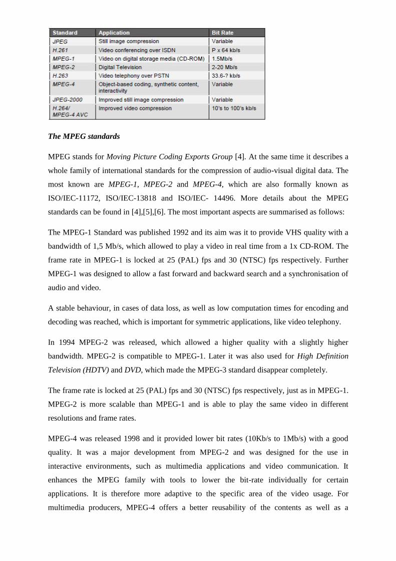
The MPEG standards
MPEG stands for Moving Picture Coding Exports Group [4]. At the same time it describes a
whole family of international standards for the compression of audio-visual digital data. The
most known are MPEG-1, MPEG-2 and MPEG-4, which are also formally known as
ISO/IEC-11172, ISO/IEC-13818 and ISO/IEC- 14496. More details about the MPEG
standards can be found in [4],[5],[6]. The most important aspects are summarised as follows:
The MPEG-1 Standard was published 1992 and its aim was it to provide VHS quality with a
bandwidth of 1,5 Mb/s, which allowed to play a video in real time from a 1x CD-ROM. The
frame rate in MPEG-1 is locked at 25 (PAL) fps and 30 (NTSC) fps respectively. Further
MPEG-1 was designed to allow a fast forward and backward search and a synchronisation of
audio and video.
A stable behaviour, in cases of data loss, as well as low computation times for encoding and
decoding was reached, which is important for symmetric applications, like video telephony.
In 1994 MPEG-2 was released, which allowed a higher quality with a slightly higher
bandwidth. MPEG-2 is compatible to MPEG-1. Later it was also used for High Definition
Television (HDTV) and DVD, which made the MPEG-3 standard disappear completely.
The frame rate is locked at 25 (PAL) fps and 30 (NTSC) fps respectively, just as in MPEG-1.
MPEG-2 is more scalable than MPEG-1 and is able to play the same video in different
resolutions and frame rates.
MPEG-4 was released 1998 and it provided lower bit rates (10Kb/s to 1Mb/s) with a good
quality. It was a major development from MPEG-2 and was designed for the use in
interactive environments, such as multimedia applications and video communication. It
enhances the MPEG family with tools to lower the bit-rate individually for certain
applications. It is therefore more adaptive to the specific area of the video usage. For
multimedia producers, MPEG-4 offers a better reusability of the contents as well as a
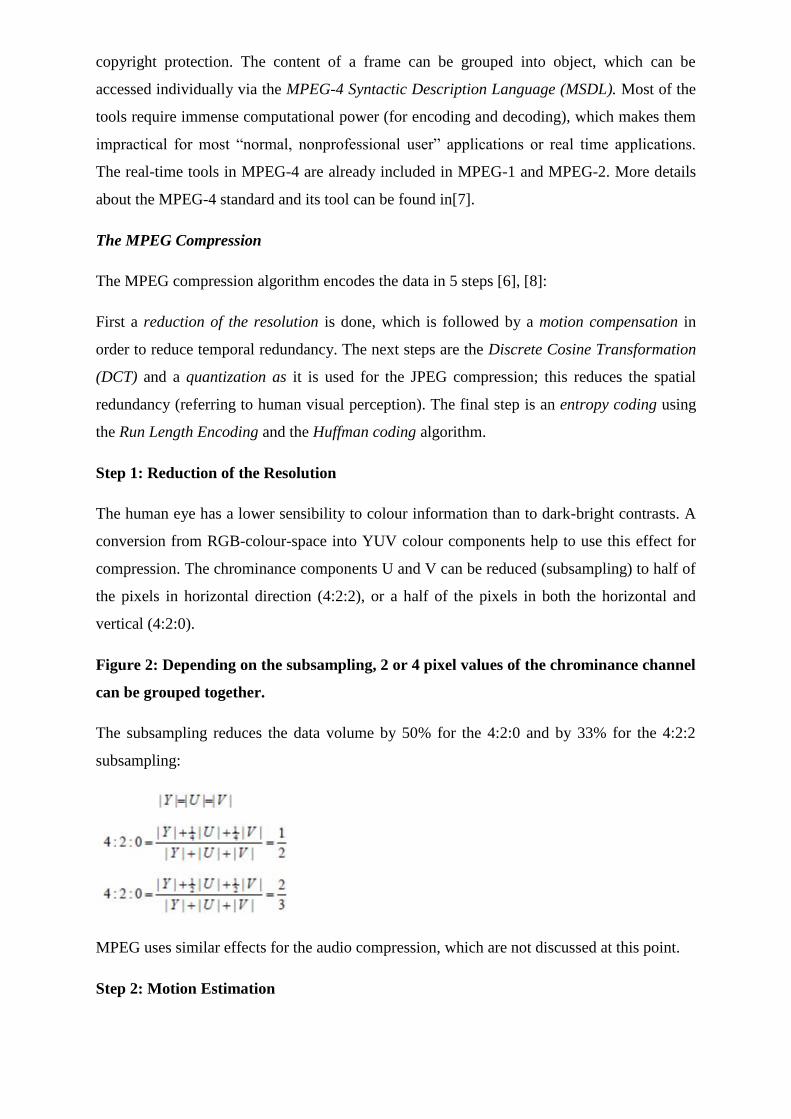
copyright protection. The content of a frame can be grouped into object, which can be
accessed individually via the MPEG-4 Syntactic Description Language (MSDL). Most of the
tools require immense computational power (for encoding and decoding), which makes them
impractical for most ―normal, nonprofessional user‖ applications or real time applications.
The real-time tools in MPEG-4 are already included in MPEG-1 and MPEG-2. More details
about the MPEG-4 standard and its tool can be found in[7].
The MPEG Compression
The MPEG compression algorithm encodes the data in 5 steps [6], [8]:
First a reduction of the resolution is done, which is followed by a motion compensation in
order to reduce temporal redundancy. The next steps are the Discrete Cosine Transformation
(DCT) and a quantization as it is used for the JPEG compression; this reduces the spatial
redundancy (referring to human visual perception). The final step is an entropy coding using
the Run Length Encoding and the Huffman coding algorithm.
Step 1: Reduction of the Resolution
The human eye has a lower sensibility to colour information than to dark-bright contrasts. A
conversion from RGB-colour-space into YUV colour components help to use this effect for
compression. The chrominance components U and V can be reduced (subsampling) to half of
the pixels in horizontal direction (4:2:2), or a half of the pixels in both the horizontal and
vertical (4:2:0).
Figure 2: Depending on the subsampling, 2 or 4 pixel values of the chrominance channel
can be grouped together.
The subsampling reduces the data volume by 50% for the 4:2:0 and by 33% for the 4:2:2
subsampling:
MPEG uses similar effects for the audio compression, which are not discussed at this point.
Step 2: Motion Estimation
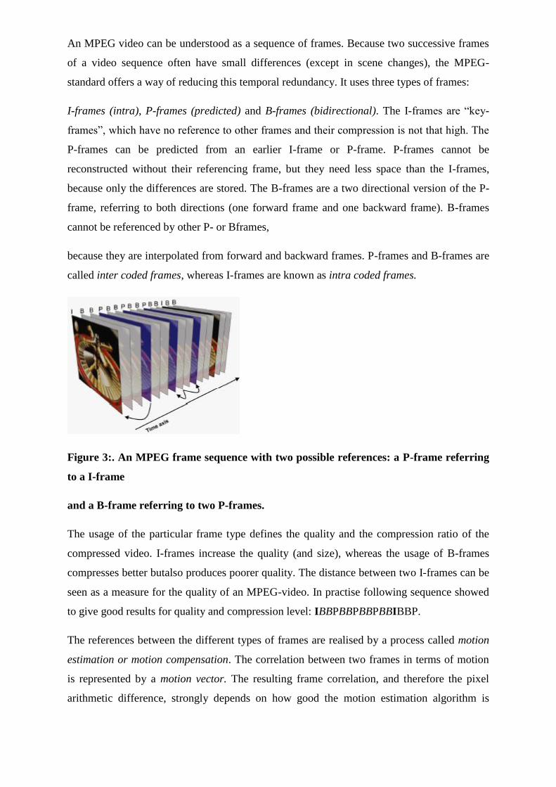
An MPEG video can be understood as a sequence of frames. Because two successive frames
of a video sequence often have small differences (except in scene changes), the MPEG-
standard offers a way of reducing this temporal redundancy. It uses three types of frames:
I-frames (intra), P-frames (predicted) and B-frames (bidirectional). The I-frames are ―key-
frames‖, which have no reference to other frames and their compression is not that high. The
P-frames can be predicted from an earlier I-frame or P-frame. P-frames cannot be
reconstructed without their referencing frame, but they need less space than the I-frames,
because only the differences are stored. The B-frames are a two directional version of the P-
frame, referring to both directions (one forward frame and one backward frame). B-frames
cannot be referenced by other P- or Bframes,
because they are interpolated from forward and backward frames. P-frames and B-frames are
called inter coded frames, whereas I-frames are known as intra coded frames.
Figure 3:. An MPEG frame sequence with two possible references: a P-frame referring
to a I-frame
and a B-frame referring to two P-frames.
The usage of the particular frame type defines the quality and the compression ratio of the
compressed video. I-frames increase the quality (and size), whereas the usage of B-frames
compresses better butalso produces poorer quality. The distance between two I-frames can be
seen as a measure for the quality of an MPEG-video. In practise following sequence showed
to give good results for quality and compression level: IBBPBBPBBPBBIBBP.
The references between the different types of frames are realised by a process called motion
estimation or motion compensation. The correlation between two frames in terms of motion
is represented by a motion vector. The resulting frame correlation, and therefore the pixel
arithmetic difference, strongly depends on how good the motion estimation algorithm is
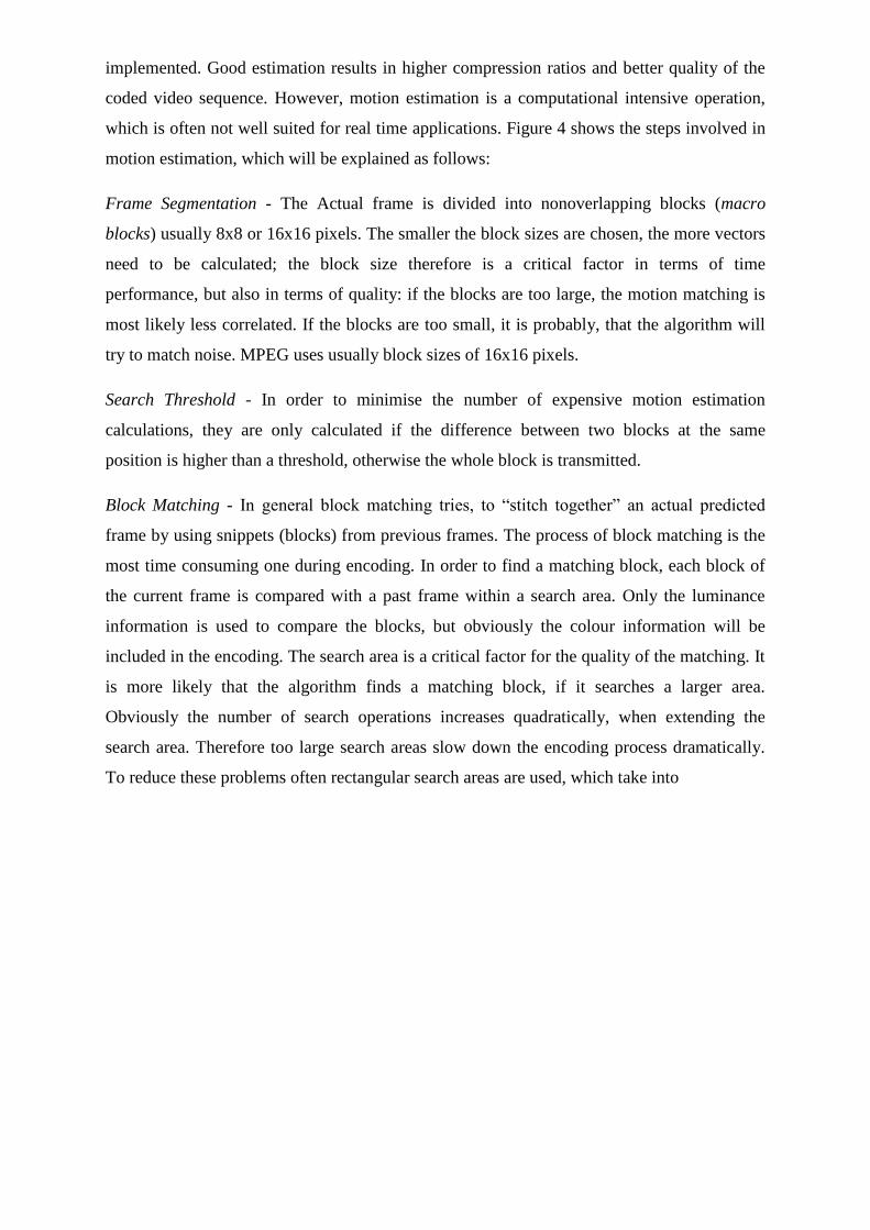
implemented. Good estimation results in higher compression ratios and better quality of the
coded video sequence. However, motion estimation is a computational intensive operation,
which is often not well suited for real time applications. Figure 4 shows the steps involved in
motion estimation, which will be explained as follows:
Frame Segmentation - The Actual frame is divided into nonoverlapping blocks (macro
blocks) usually 8x8 or 16x16 pixels. The smaller the block sizes are chosen, the more vectors
need to be calculated; the block size therefore is a critical factor in terms of time
performance, but also in terms of quality: if the blocks are too large, the motion matching is
most likely less correlated. If the blocks are too small, it is probably, that the algorithm will
try to match noise. MPEG uses usually block sizes of 16x16 pixels.
Search Threshold - In order to minimise the number of expensive motion estimation
calculations, they are only calculated if the difference between two blocks at the same
position is higher than a threshold, otherwise the whole block is transmitted.
Block Matching - In general block matching tries, to ―stitch together‖ an actual predicted
frame by using snippets (blocks) from previous frames. The process of block matching is the
most time consuming one during encoding. In order to find a matching block, each block of
the current frame is compared with a past frame within a search area. Only the luminance
information is used to compare the blocks, but obviously the colour information will be
included in the encoding. The search area is a critical factor for the quality of the matching. It
is more likely that the algorithm finds a matching block, if it searches a larger area.
Obviously the number of search operations increases quadratically, when extending the
search area. Therefore too large search areas slow down the encoding process dramatically.
To reduce these problems often rectangular search areas are used, which take into
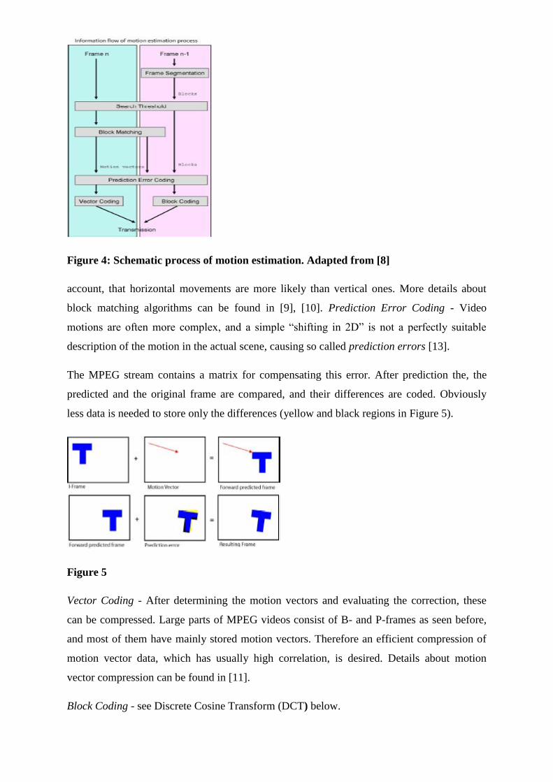
Figure 4: Schematic process of motion estimation. Adapted from [8]
account, that horizontal movements are more likely than vertical ones. More details about
block matching algorithms can be found in [9], [10]. Prediction Error Coding - Video
motions are often more complex, and a simple ―shifting in 2D‖ is not a perfectly suitable
description of the motion in the actual scene, causing so called prediction errors [13].
The MPEG stream contains a matrix for compensating this error. After prediction the, the
predicted and the original frame are compared, and their differences are coded. Obviously
less data is needed to store only the differences (yellow and black regions in Figure 5).
Figure 5
Vector Coding - After determining the motion vectors and evaluating the correction, these
can be compressed. Large parts of MPEG videos consist of B- and P-frames as seen before,
and most of them have mainly stored motion vectors. Therefore an efficient compression of
motion vector data, which has usually high correlation, is desired. Details about motion
vector compression can be found in [11].
Block Coding - see Discrete Cosine Transform (DCT) below.
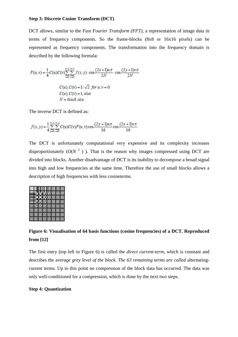
Step 3: Discrete Cosine Transform (DCT)
DCT allows, similar to the Fast Fourier Transform (FFT), a representation of image data in
terms of frequency components. So the frame-blocks (8x8 or 16x16 pixels) can be
represented as frequency components. The transformation into the frequency domain is
described by the following formula:
The inverse DCT is defined as:
The DCT is unfortunately computational very expensive and its complexity increases
disproportionately (O(N 2 ) ). That is the reason why images compressed using DCT are
divided into blocks. Another disadvantage of DCT is its inability to decompose a broad signal
into high and low frequencies at the same time. Therefore the use of small blocks allows a
description of high frequencies with less cosineterms.
Figure 6: Visualisation of 64 basis functions (cosine frequencies) of a DCT. Reproduced
from [12]
The first entry (top left in Figure 6) is called the direct current-term, which is constant and
describes the average grey level of the block. The 63 remaining terms are called alternating-
current terms. Up to this point no compression of the block data has occurred. The data was
only well-conditioned for a compression, which is done by the next two steps.
Step 4: Quantization
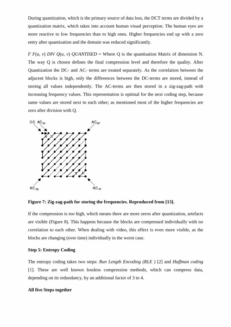
During quantization, which is the primary source of data loss, the DCT terms are divided by a
quantization matrix, which takes into account human visual perception. The human eyes are
more reactive to low frequencies than to high ones. Higher frequencies end up with a zero
entry after quantization and the domain was reduced significantly.
F F(u, v) DIV Q(u, v) QUANTISED = Where Q is the quantisation Matrix of dimension N.
The way Q is chosen defines the final compression level and therefore the quality. After
Quantization the DC- and AC- terms are treated separately. As the correlation between the
adjacent blocks is high, only the differences between the DC-terms are stored, instead of
storing all values independently. The AC-terms are then stored in a zig-zag-path with
increasing frequency values. This representation is optimal for the next coding step, because
same values are stored next to each other; as mentioned most of the higher frequencies are
zero after division with Q.
Figure 7: Zig-zag-path for storing the frequencies. Reproduced from [13].
If the compression is too high, which means there are more zeros after quantization, artefacts
are visible (Figure 8). This happens because the blocks are compressed individually with no
correlation to each other. When dealing with video, this effect is even more visible, as the
blocks are changing (over time) individually in the worst case.
Step 5: Entropy Coding
The entropy coding takes two steps: Run Length Encoding (RLE ) [2] and Huffman coding
[1]. These are well known lossless compression methods, which can compress data,
depending on its redundancy, by an additional factor of 3 to 4.
All five Steps together
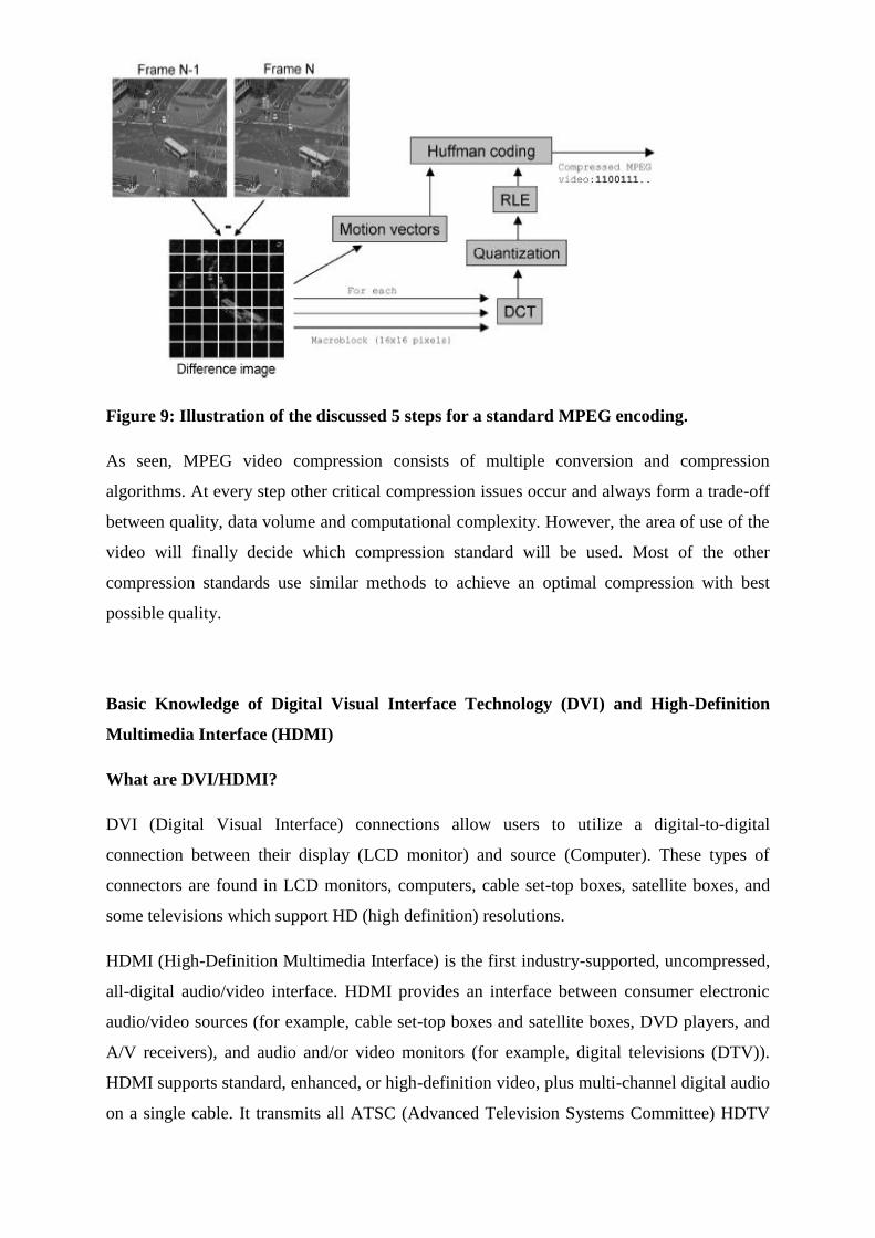
Figure 9: Illustration of the discussed 5 steps for a standard MPEG encoding.
As seen, MPEG video compression consists of multiple conversion and compression
algorithms. At every step other critical compression issues occur and always form a trade-off
between quality, data volume and computational complexity. However, the area of use of the
video will finally decide which compression standard will be used. Most of the other
compression standards use similar methods to achieve an optimal compression with best
possible quality.
Basic Knowledge of Digital Visual Interface Technology (DVI) and High-Definition
Multimedia Interface (HDMI)
What are DVI/HDMI?
DVI (Digital Visual Interface) connections allow users to utilize a digital-to-digital
connection between their display (LCD monitor) and source (Computer). These types of
connectors are found in LCD monitors, computers, cable set-top boxes, satellite boxes, and
some televisions which support HD (high definition) resolutions.
HDMI (High-Definition Multimedia Interface) is the first industry-supported, uncompressed,
all-digital audio/video interface. HDMI provides an interface between consumer electronic
audio/video sources (for example, cable set-top boxes and satellite boxes, DVD players, and
A/V receivers), and audio and/or video monitors (for example, digital televisions (DTV)).
HDMI supports standard, enhanced, or high-definition video, plus multi-channel digital audio
on a single cable. It transmits all ATSC (Advanced Television Systems Committee) HDTV
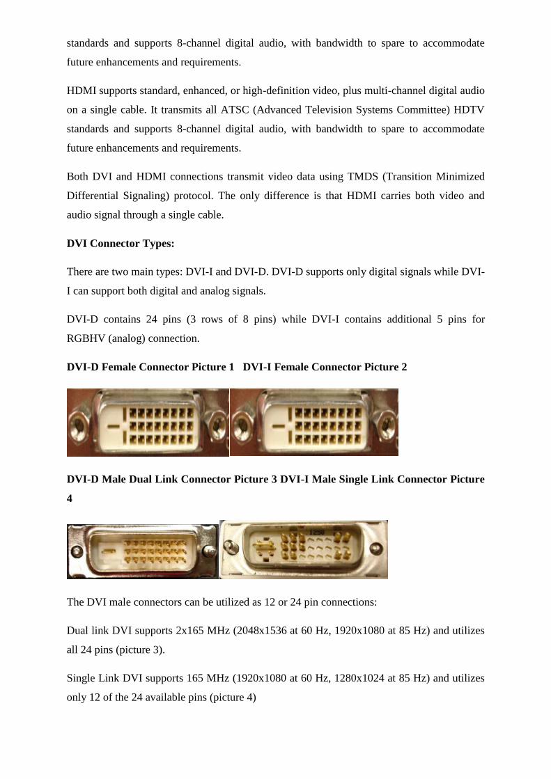
standards and supports 8-channel digital audio, with bandwidth to spare to accommodate
future enhancements and requirements.
HDMI supports standard, enhanced, or high-definition video, plus multi-channel digital audio
on a single cable. It transmits all ATSC (Advanced Television Systems Committee) HDTV
standards and supports 8-channel digital audio, with bandwidth to spare to accommodate
future enhancements and requirements.
Both DVI and HDMI connections transmit video data using TMDS (Transition Minimized
Differential Signaling) protocol. The only difference is that HDMI carries both video and
audio signal through a single cable.
DVI Connector Types:
There are two main types: DVI-I and DVI-D. DVI-D supports only digital signals while DVI-
I can support both digital and analog signals.
DVI-D contains 24 pins (3 rows of 8 pins) while DVI-I contains additional 5 pins for
RGBHV (analog) connection.
DVI-D Female Connector Picture 1 DVI-I Female Connector Picture 2
DVI-D Male Dual Link Connector Picture 3 DVI-I Male Single Link Connector Picture
4
The DVI male connectors can be utilized as 12 or 24 pin connections:
Dual link DVI supports 2x165 MHz (2048x1536 at 60 Hz, 1920x1080 at 85 Hz) and utilizes
all 24 pins (picture 3).
Single Link DVI supports 165 MHz (1920x1080 at 60 Hz, 1280x1024 at 85 Hz) and utilizes
only 12 of the 24 available pins (picture 4)
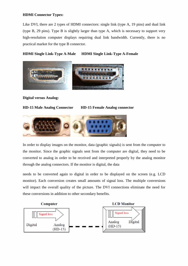
HDMI Connector Types:
Like DVI, there are 2 types of HDMI connectors: single link (type A, 19 pins) and dual link
(type B, 29 pins). Type B is slightly larger than type A, which is necessary to support very
high-resolution computer displays requiring dual link bandwidth. Currently, there is no
practical market for the type B connector.
HDMI Single Link-Type A-Male HDMI Single Link-Type A-Female
Digital versus Analog:
HD-15 Male Analog Connector HD-15 Female Analog connector
In order to display images on the monitor, data (graphic signals) is sent from the computer to
the monitor. Since the graphic signals sent from the computer are digital, they need to be
converted to analog in order to be received and interpreted properly by the analog monitor
through the analog connectors. If the monitor is digital, the data
needs to be converted again to digital in order to be displayed on the screen (e.g. LCD
monitor). Each conversion creates small amounts of signal loss. The multiple conversions
will impact the overall quality of the picture. The DVI connections eliminate the need for
these conversions in addition to other secondary benefits.
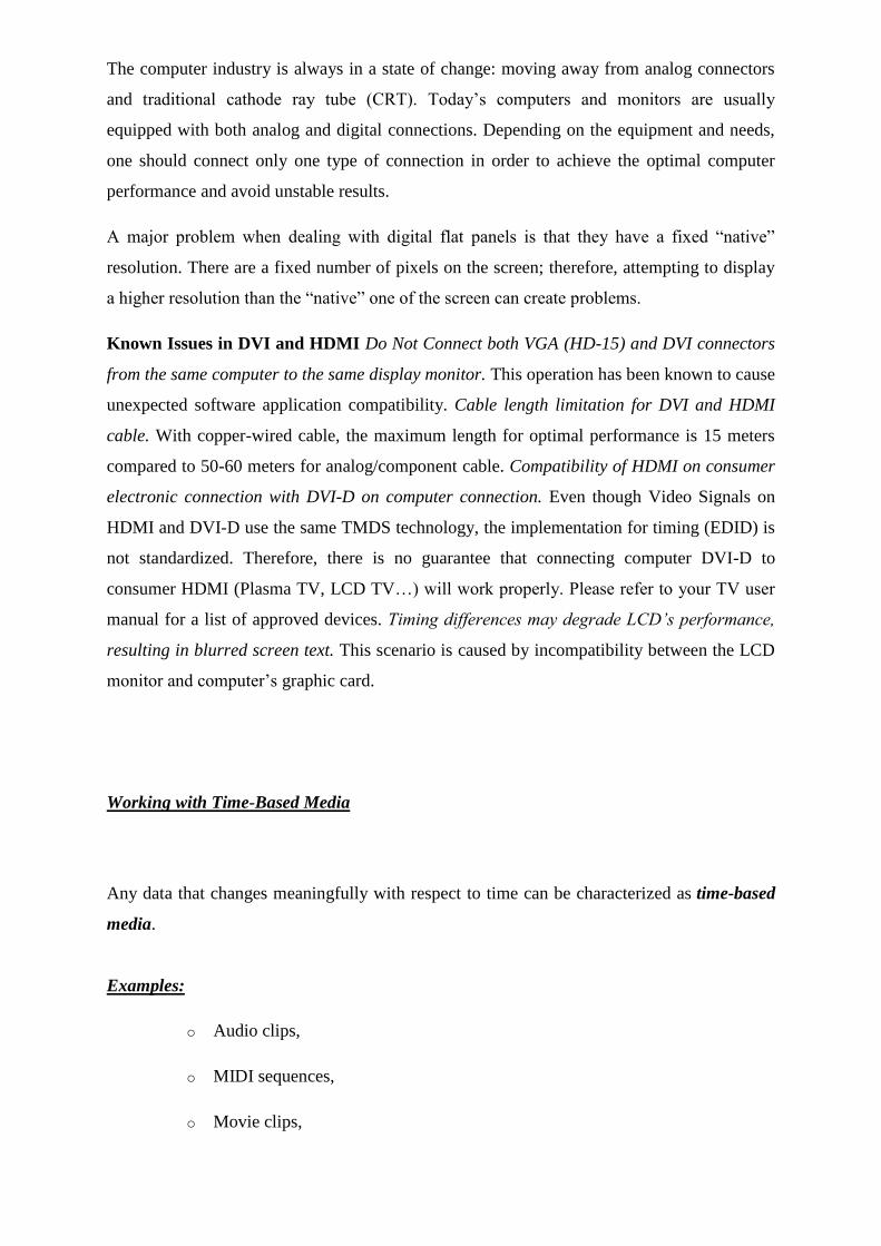
The computer industry is always in a state of change: moving away from analog connectors
and traditional cathode ray tube (CRT). Today‘s computers and monitors are usually
equipped with both analog and digital connections. Depending on the equipment and needs,
one should connect only one type of connection in order to achieve the optimal computer
performance and avoid unstable results.
A major problem when dealing with digital flat panels is that they have a fixed ―native‖
resolution. There are a fixed number of pixels on the screen; therefore, attempting to display
a higher resolution than the ―native‖ one of the screen can create problems.
Known Issues in DVI and HDMI Do Not Connect both VGA (HD-15) and DVI connectors
from the same computer to the same display monitor. This operation has been known to cause
unexpected software application compatibility. Cable length limitation for DVI and HDMI
cable. With copper-wired cable, the maximum length for optimal performance is 15 meters
compared to 50-60 meters for analog/component cable. Compatibility of HDMI on consumer
electronic connection with DVI-D on computer connection. Even though Video Signals on
HDMI and DVI-D use the same TMDS technology, the implementation for timing (EDID) is
not standardized. Therefore, there is no guarantee that connecting computer DVI-D to
consumer HDMI (Plasma TV, LCD TV…) will work properly. Please refer to your TV user
manual for a list of approved devices. Timing differences may degrade LCD’s performance,
resulting in blurred screen text. This scenario is caused by incompatibility between the LCD
monitor and computer‘s graphic card.
Working with Time-Based Media
Any data that changes meaningfully with respect to time can be characterized as time-based
media.
Examples:
o Audio clips,
o MIDI sequences,
o Movie clips,
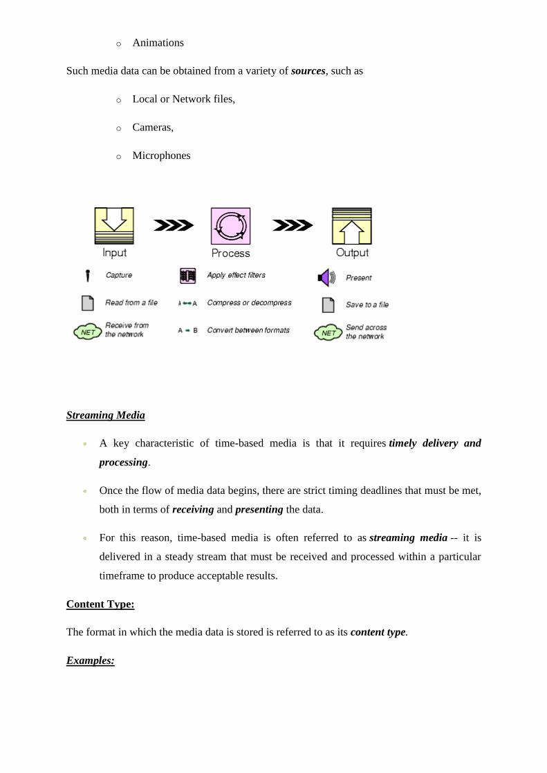
o Animations
Such media data can be obtained from a variety of sources, such as
o Local or Network files,
o Cameras,
o Microphones
Streaming Media
A key characteristic of time-based media is that it requires timely delivery and
processing.
Once the flow of media data begins, there are strict timing deadlines that must be met,
both in terms of receiving and presenting the data.
For this reason, time-based media is often referred to as streaming media -- it is
delivered in a steady stream that must be received and processed within a particular
timeframe to produce acceptable results.
Content Type:
The format in which the media data is stored is referred to as its content type.
Examples:
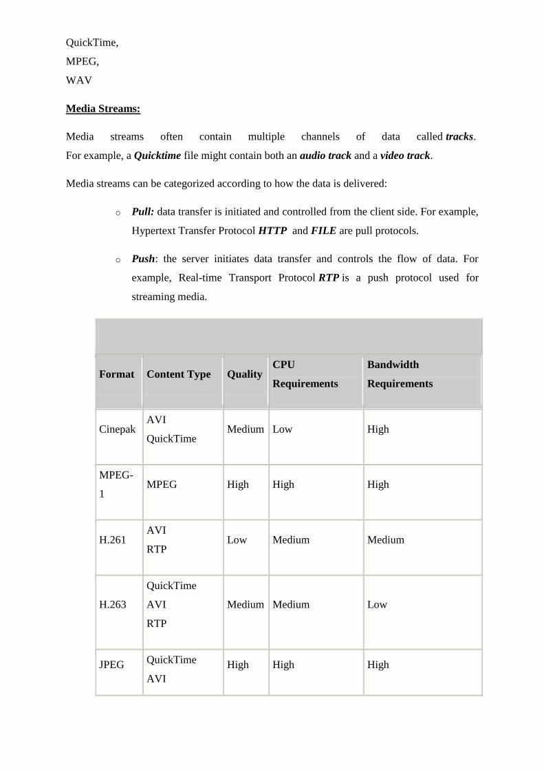
QuickTime,
MPEG,
WAV
Media Streams:
Media streams often contain multiple channels of data called tracks.
For example, a Quicktime file might contain both an audio track and a video track.
Media streams can be categorized according to how the data is delivered:
o Pull: data transfer is initiated and controlled from the client side. For example,
Hypertext Transfer Protocol HTTP and FILE are pull protocols.
o Push: the server initiates data transfer and controls the flow of data. For
example, Real-time Transport Protocol RTP is a push protocol used for
streaming media.
Format Content Type Quality CPU
Requirements
Bandwidth
Requirements
Cinepak AVI
QuickTime Medium Low High
MPEG-
1 MPEG High High High
H.261 AVI
RTP Low Medium Medium
H.263
QuickTime
AVI
RTP
Medium Medium Low
JPEG QuickTime
AVI
High High High
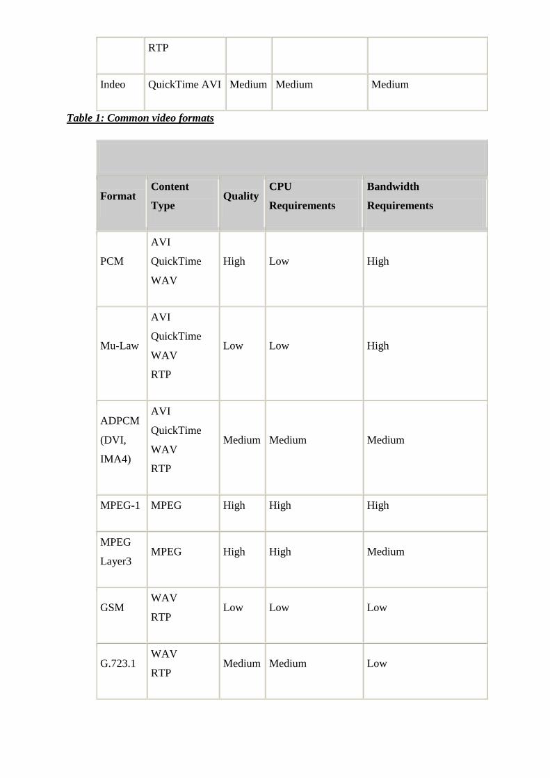
RTP
Indeo QuickTime AVI Medium Medium Medium
Table 1: Common video formats
Format Content
Type Quality
CPU
Requirements
Bandwidth
Requirements
PCM
AVI
QuickTime
WAV
High Low High
Mu-Law
AVI
QuickTime
WAV
RTP
Low Low High
ADPCM
(DVI,
IMA4)
AVI
QuickTime
WAV
RTP
Medium Medium Medium
MPEG-1 MPEG High High High
MPEG
Layer3 MPEG High High Medium
GSM WAV
RTP Low Low Low
G.723.1 WAV
RTP Medium Medium Low
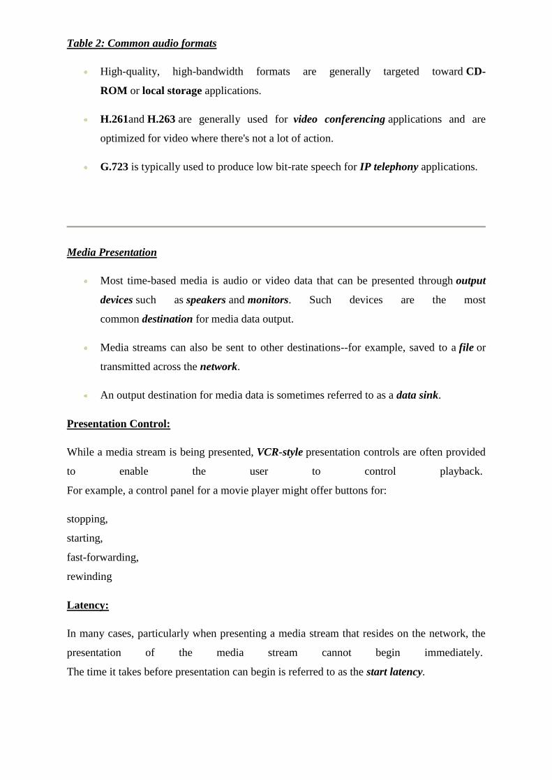
Table 2: Common audio formats
High-quality, high-bandwidth formats are generally targeted toward CD-
ROM or local storage applications.
H.261and H.263 are generally used for video conferencing applications and are
optimized for video where there's not a lot of action.
G.723 is typically used to produce low bit-rate speech for IP telephony applications.
Media Presentation
Most time-based media is audio or video data that can be presented through output
devices such as speakers and monitors. Such devices are the most
common destination for media data output.
Media streams can also be sent to other destinations--for example, saved to a file or
transmitted across the network.
An output destination for media data is sometimes referred to as a data sink.
Presentation Control:
While a media stream is being presented, VCR-style presentation controls are often provided
to enable the user to control playback.
For example, a control panel for a movie player might offer buttons for:
stopping,
starting,
fast-forwarding,
rewinding
Latency:
In many cases, particularly when presenting a media stream that resides on the network, the
presentation of the media stream cannot begin immediately.
The time it takes before presentation can begin is referred to as the start latency.
Multimedia presentations often combine several types of time-based media into
a synchronized presentation. For example:
o background music might be played during an image slide-show,
o animated text might be synchronized with an audio or video clip.
When the presentation of multiple media streams is synchronized, it is essential to take into
account the start latency of each stream--otherwise the playback of the different streams
might actually begin at different times.
Presentation Quality:
The quality of the presentation of a media stream depends on several factors, including:
o The compression scheme used
o The processing capability of the playback system
o The bandwidth available (for media streams acquired over the network)
Traditionally, the higher the quality, the larger the file size and the greater the processing
power and bandwidth required.
Bandwidth is usually represented as the number of bits that are transmitted in a certain period
of time--the bit rate.
To achieve high-quality video presentations, the number of frames displayed in each period
of time, the frame rate, should be as high as possible.
Usually movies at a frame rate of 30 frames-per-second are considered indistinguishable
from regular TV broadcasts or video tapes.
Media Processing
In most instances, the data in a media stream is manipulated before it is presented to the user:
o If the stream is multiplexed, the individual tracks are extracted.
o If the individual tracks are compressed, they are decoded.
o If necessary, the tracks are converted to a different format.
o If desired, effect filters are applied to the decoded tracks.
Demultiplexers and Multiplexers:
o A demultiplexer extracts individual tracks of media data from a multiplexed
media stream.
o A mutliplexer performs the opposite function, it takes individual tracks of
media data and merges them into a single multiplexed media stream.
Codecs:
o A codec performs media-data compression and decompression.
o When a track is encoded, it is converted to a compressed format suitable for
storage or transmission.
o When it is decoded it is converted to a non-compressed (raw) format suitable
for presentation.
Effect Filters:
o An effect filter modifies the track data in some way, often to create special
effects such as blur or echo.
o Typically, effect filters are applied to uncompressed (raw) data.
Renderers:
o A renderer is an abstraction of a presentation device.
o For audio, the presentation device is typically the computer's hardware audio
card that outputs sound to the speakers.
o For video, the presentation device is typically the computer monitor.
Compositing:
o Certain specialized devices support compositing.
o Compositing time-based media is the process of combining multiple tracks of
data onto a single presentation medium.
o For example, overlaying text on a video presentation is one common form of
compositing.
Media Capture
o Time-based media can be captured from a live source for processing and
playback.
o For example:
audio can be captured from a microphone or
video capture card can be used to obtain video from a camera.
o Capturing can be thought of as the input phase of the standard media
processing model.
Capture Devices:
o Capture devices can be characterized as either push or pull sources.
o For example:
A still camera is a pull source--the user controls when to capture an image.
A microphone is a push source--the live source continuously provides a stream of audio.
Capture Controls:
A capture control panel might enable the user to specify:
o data rate,
o encoding type for the captured stream, and
o start and stop of the capture process.
QUESTIONS

1. Explain audio compression and decompression?
2. What is DVI technology?
3.Explain the difference between I-frame and P-frame?
4. Explain hardware aspects of MIDI.
5. Explain MIDI to WAV conversion?
6. Explain quantization and transmission of audio?
7. What is the role of multimedia in speech recognition?
CHAPTER 5
VIRTUAL REALITY
Virtual Reality
This is a complex and at times, esoteric subject which continues to fascinate a great many
people. Yet there is a certain amount of cynicism towards virtual reality or ‗VR‘ for short
which in the early days, promised so much but did not always deliver.
We have also included a section about augmented reality: this is a similar form of
technology in which the lines are blurred between the real world and computer generated
imagery, e.g. video. Sound, video or images are overlaid onto a real world environment in
order to enhance the user experience.
In-depth look at the world of virtual reality
But what is virtual reality and how does it work-
Virtual Reality
Virtual Reality Games
Virtual Reality Gear
Virtual Reality and the Military
Virtual Reality and Education
Virtual Reality and Healthcare
Augmented Reality
Virtual reality is considered to have wide ranging benefits for the healthcare sector but, it can
be used in other sectors as well which include:
Education
Gaming
Architecture
The military
In many ways, this technology has far more possibilities than originally thought. But it is
important not to confuse fact with fiction.
Whilst virtual reality may appear a futuristic concept which dwells in the realm of science
fiction it is, nevertheless, a very real form of technology. And this real form of technology
has the potential to deliver real-world benefits to a great many people.
Virtual Reality
Virtual reality is a form of technology which creates computer generated worlds or
immersive environments which people can explore and in many cases, interact with.
Virtual reality has its advocates and opponents which are mainly due to a lack of
understanding about this technology and its capabilities. Unrealistic expectations coupled
with lack of awareness regarding technical limitations means that for many people, virtual
reality is difficult to grasp or even take seriously.
This topic aims to educate and inform anyone interested in virtual reality. This includes the
casual observer through to the teenager fixated on virtual reality gaming through to the
healthcare professional or engineer.
We have also included a section about the human factors issues of virtual reality for those of
you who work in usability, user experience (UX) or any other user-centred discipline.
A step by step approach to virtual reality
This topic is organised into the following sections:
What is virtual reality?
Virtual reality concepts
When virtual reality was invented
How is virtual reality possible?
How virtual reality is used
How does virtual reality affect us?
Assessment of virtual reality systems
What is Virtual Reality?
The definition of virtual reality comes, naturally, from the definitions for both ‗virtual‘ and
‗reality‘. The definition of ‗virtual‘ is near and reality is what we experience as human
beings. So the term ‗virtual reality‘ basically means ‗near-reality‘. This could, of course,
mean anything but it usually refers to a specific type of reality emulation.
So what is virtual reality?
Answering "what is virtual reality" in technical terms is straight-forward. Virtual reality is the
term used to describe a three-dimensional, computer generated environment which can be
explored and interacted with by a person. That person becomes part of this virtual world or is
immersed within this environment and whilst there, is able to manipulate objects or perform a
series of actions.
The person wears a head-mounted display (HMD) or glasses which displays three-
dimensional images as part of their experience. Some systems enable the person to
experience additional sensory input, e.g. sound or video which contributes to their overall
experience.
Multi-sensory experience
They are aided by various sensory stimuli such as sound, video and images which form part
of most virtual reality environments. But many newer environments include touch or force
feedback through a haptic device such as a ‗data glove‘ which further enhances the
experience.
Virtual environments
Many people who work with virtual reality prefer to use the term ‗virtual environments‘
instead. This is a response to a perceived negativity to this technology which has often turned
out to be true. There are people who view virtual reality with little enthusiasm and dismiss it
as ‗science fiction‘, seeing it as having no practical application in the real world.
Variety of uses
But there are in fact, a wide variety of applications for virtual reality which include:
Architecture
Sport
Medicine
The Arts
Entertainment
Virtual reality can lead to new and exciting discoveries in these areas which impact upon our
day to day lives. One example of this is the use of virtual reality in medicine, such as surgical
simulations, which helps with training the next generation of surgeons.
Features of virtual reality systems
There are many different types of virtual reality systems but they all share the same
characteristics such as the ability to allow the person to view three-dimensional images.
These images appear life-sized to the person.
Plus they change as the person moves around their environment which corresponds with the
change in their field of vision. The aim is for a seamless join between the person‘s head and
eye movements and the appropriate response, e.g. change in perception. This ensures that the
virtual environment is both realistic and enjoyable.
A virtual environment should provide the appropriate responses – in real time- as the
person explores their surroundings. The problems arise when there is a delay between the
person‘s actions and system response or latency which then disrupts their experience. The
person becomes aware that they are in an artificial environment and adjusts their behaviour
accordingly which results in a stilted, mechanical form of interaction.
The aim is for a natural, free-flowing form of interaction which will result in a memorable
experience.
Virtual Reality Concepts
The concepts behind virtual reality are based upon theories about a long held human desire
to escape the boundaries of the ‘real world’ by embracing cyberspace. Once there we can
interact with this virtual environment in a more naturalistic manner which will generate new
forms of human-machine interaction(HMI).
Beyond the keyboard and mouse
The aim is to move beyond standard forms of interaction such as the keyboard and mouse
which most people work with on a daily basis. This is seen as an unnatural way of working
which forces people to adapt to the demands of the technology rather than the other way
around.
But a virtual environment does the opposite. It allows someone to fully immerse
themselves in a highly visual world which they explore by means of their senses. This natural
form of interaction within this world often results in new forms of communication and
understanding.
Freedom within the 3D virtual environment
The experience of a virtual world mimics that of a real world scenario but often without
many of its constraints. Virtual reality enables allows someone to do the following:
Walk around a three-dimensional building
Perform a virtual operation
Play a multi-user game
Take part in a theatre of war
Interact with an artwork, e.g. installation
Plus the fact that they can do this in a 3D environment means that they replicate an
experience similar to that in the real world but without many of the dangers.
This is preferable to trying to simulate these experiences in a two-dimensional setting, e.g. a
computer desktop.
Problem solving with virtual reality
Virtual reality also acts as a problem solving device in that it enables us to explore various
options as a means of finding an answer to a problem.
For example, an engineering company will use virtual reality to produce a prototype which
is then tested and the results fed back to the design team. The advantage of this is that it
enables the designers to make alterations to their design but at far less time and cost.
This is a preferred option to building a physical prototype which is expensive to build and
make changes to: especially if it undergoes several alterations as part of the design process.
How is Virtual Reality Possible?
Virtual reality is possible thanks to developments in interactive technologies by people such
as Jaron Lanier ,Douglas Engelbart, Ivan Sutherland and Morton Heilig
These people were pushing the boundaries of technological research and experimented with
new forms of input devices, user interfaces, multimedia and 360 degrees user experience.
Technological advances
Plus advances in film, television and the media also contributed to these developments. This
has continued to this day with the creation of virtual reality gaming for example the Nintendo
Wii which uses a handheld controller as a tracking device. The gamer uses this to interact
with objects on the screen in front of them and as a result, changes the interaction.
This combined with advancements in graphics and video technology and the emergence of
virtual worlds such as ‗Second Life‘ mean that we can fully engage with these environments
in ways which we had never previously considered.
Find out more in the virtual reality games section.
Virtual reality is currently being used to create virtual environments such as those seen in
military applications. They use these for training purposes for example, flight simulators as
well as battle scenarios, e.g. searching for unexploded bombs.
Advances in computing
It is a combination of several things such as an increase in processing speed, bigger and better
graphics cards, advances in interactive technologies, increased interest in virtual worlds and
not forgetting, web 2.0 in which the dominant theme is interactivity.
Web 2.0
The internet plays an important part in all of this. There has been a shift from the idea of the
web as a passive experience to web 2.0 in which we as users play a far greater role. Users
generate content which is shared with millions of others as can be seen in the rise of social
media, e.g. Facebook and Twitter.
All of these put users firmly in the driving seat. We control the means of interaction and help
to create new and exciting forms of interaction which will drive future developments in
virtual reality.
How is Virtual Reality Used?
Related Articles
Virtual Reality
What is Virtual Reality?
Virtual Reality Concepts
Virtual Reality Applications
Virtual Reality Immersion
The Virtual Reality Ambience And Atmosphere
Interactivity Element
The Virtual Reality Headset
Games In Virtual Reality
Applications Of Virtual Reality
History Of Virtual Reality
Developments In Virtual Reality
Latest Developments in Virtual Reality
There are numerous ways virtual reality can be used which provide enormous benefits to us.
These include:
Healthcare/surgery
Military
Architecture
Art
Entertainment
Education
Business
The media
Sport
Rehabilitation/treatment of phobias

The list of applications for VR is endless. Virtual reality may have been considered an
overnight sensation but it has been re-invented under the term ‗virtual environments‘ and is
proving to be useful in ways which had never been previously considered.
VR variety of applications
Medicine is one of the biggest beneficiaries with the development of surgery simulation. This
is often used as a training aid and enables the surgeon to perform an operation on a ‗virtual
patient‘ or to see inside the human body. It is also used as a diagnostic tool in that it provides
a more detail view of the human body compared to X-rays and scans.
Another popular use of virtual reality is aviation: a three dimensional aircraft can be designed
which allows the designer to test their prototype without having to have several versions –
which are time consuming and costly.
It is cheaper and easier to make changes to the simulation rather than having to design and
build a new aircraft.
Games, surgery and flight simulators are the most well known uses of virtual reality but
other, lesser well known applications include:
Visualisations, e.g. geographical
Study and treatment of addictions
Weather forecasting
Historical, e.g. re-creating ancient civilisations
Data analysis, e.g. financial data
There may be additional applications which we have not heard about.
How Does Virtual Reality Affect Us?
We assume that virtual reality is a benign influence upon our lives and is not likely to cause
any problems. But this is a form of technology which is developing all the time and as a
result, can throw up problems which had not been previously considered.
There are physical problems which are due to poor ergonomics and then there are
psychological issues. Then there are moral and ethical concerns about this technology which
are discussed in greater detail in ourvirtual reality and ethical issues section.
Physical effects of virtual reality
One of the main problems with virtual reality is motion sickness. It is not unknown for people
to suffer from nausea after spending a period of time in a virtual environment which is due to
the effects the shift in perception has on balance. Our balance is affected by changes in the
inner ear which results in feelings of nausea often experienced by people when travelling on a
ship or some other form of transport.
Some people are affected by this after spending only 30 minutes in a virtual environment
whereas others can go several hours before they notice any ill effects.
Another name for this sensation is ‗cybersickness‘.
Time constraints
Another problem with virtual reality is time: it takes a long period of time to develop a virtual
environment which may not be good news for any commercial enterprise wishing to invest in
this technology. Time is money in the business world.
Plus many virtual reality companies or researchers use and adapt other forms of technology
from other sources which means that they are reliant upon these. If one of their suppliers goes
out of business then this will delay the work by a considerable period of time.
The more realistic a virtual world the longer it will take. It takes an inordinate amount of time
to create an environment which is indistinguishable from the real thing, for example, a 3D
walkthrough of a building which can a year or more to complete.
Early forms of virtual reality included blocky looking graphics and crude renderings which
did not take long to produce but would not meet today‘s ever increasing demands. People
want faster, smoother and lifelike scenarios which make greater demands on processing
speed, memory and rendering time.
There has to be a balance between hyper-realism and production time.
Assessment of Virtual Reality Systems
There has been an increased interest in virtual reality which has led to some exciting new
developments for society as a whole. This technology is viewed as a serious contender rather
than something which belongs in sci-fi films and games only.
Virtual reality has a wide range of applications which range from gaming and entertainment
through to medicine, engineering, military training, scientific visualisation and business.
But as with any technology, there are issues regarding the usability of this system. How ‗user
friendly‘ is virtual reality and how is it assessed?
Usability is discussed in more detail in the Human factors and user studies article.
Virtual reality relies upon interaction which is done via an input device such as a data glove,
wand, joystick or other type of controller. In this sense, VR can be viewed as a form of
human-computer interaction (HCI) in which information flows between the user (person) and
the technology. But the aim with HCI is to enable people or users to use the technology to
achieve a goal easily and effectively.
How to measure effective virtual reality systems
Does virtual reality do this? Does it fit into the category of ‗ease of use‘ and how do we
measure its effectiveness?
The problem is that existing usability guidelines are designed for standard user interfaces
such as a desktop computer in which the user interacts with information in a two dimensional
space.
But virtual reality is a 3D system which enables users to interact with objects with a computer
generated environment, often utilising their senses as well. The aim is to generate an
experience which is indistinguishable from the real world.
The issue is that of developing usability guidelines for virtual reality systems which ensure
that they are easy to use, effective and efficient. Virtual reality has its own particular issues
which require a different approach to that used for other interactive systems.
Educational guide to virtual reality
For example, the originator of the term ‗virtual reality‘ was a pioneering computer scientist
called Jaron Lanierwho devised this term in 1987.
However, some would argue that virtual reality – as a concept - has been around for much
longer than that. In fact, it can be traced back to the early 1960‘s with the development of the
first head mounted display (HMD) entitled ‗Headsight‘ by the Philco corporation.
The background to virtual reality is discussed at greater length in the when virtual reality was
invented section.
Pros and cons of virtual reality
This is then followed by a series of articles about the various applications of this technology
and the equipment used, for example, VR glasses (or goggles as they are sometimes called).
This is where you can find out more about the two types of virtual environments:
Semi-immersive VR
CAVE VR
Both of these result in very different types of experiences.
A virtual environment needs to place the user at its centre and ensure that he or she has a
productive experience which they are likely to repeat. But a common problem with virtual
reality systems is motion sickness which is caused by poor ergonomics and a lack of
awareness of the physical needs of the user. This, as one of the disadvantages of virtual
reality, is something which needs to be addressed.
Intelligent Multimedia Computer Systems: Emerging Information Resources in the Network
Environment
Charles W. Bailey, Jr.
A multimedia computer system is one that can create, import, integrate, store, retrieve, edit,
and delete two or more types of media materials in digital form, such as audio, image, full-
motion video, and text information. This paper surveys four possible types of multimedia
computer systems: hypermedia, multimedia database, multimedia message, and virtual reality
systems. The primary focus is on advanced multimedia systems development projects and
theoretical efforts that suggest long-term trends in this increasingly important area.
Introduction
A multimedia computer system is a computer system that can create, import, integrate, store,
retrieve, edit, and delete two or more types of media materials in digital form, such as audio,
image, full-motion video, and text information. Multimedia computer systems also may have
the ability to analyze media materials (e.g., counting the number of occurrences of a word in
a text file). A multimedia computer system can be a single- or multiple-user system.
Networked multimedia computer systems can transmit and receive digital multimedia
materials over a single computer network or over any number of interconnected computer
networks. As multimedia computer systems evolve, they may become intelligent systems by
utilizing expert system technology to assist users in selecting, retrieving, and manipulating
multimedia information.
This paper surveys four possible types of multimedia computer systems: hypermedia,
multimedia database, multimedia message, and virtual reality systems. It examines the
potential benefits and problems associated with the use of multimedia computer systems as
public-access computer systems, which can be employed directly by library patrons.1
Without question, multimedia computer systems will have a profound impact on library
systems that are used for internal purposes; however, this area is beyond the scope of the
present paper. This paper also does not attempt to survey the wide array of supporting
hardware (e.g., CD-I, CD-ROM XA, and DVI) and software products (e.g., BASISplus and
HyperCard) that will be used to build multimedia computer systems. Several recent papers
introduce the reader to these topics.2-4 Rather, it primarily focuses on advanced multimedia
system development projects and theoretical efforts that suggest long-term trends in this
increasingly important area.
We are in a period of rapid technological change where new computing technologies will
quickly evolve and converge, creating hybrid computing systems from the cross-fertilization
of previously discrete products and research areas. The four categories of systems suggested
in this paper are intended to provide the reader with a conceptual framework for thinking
about the emerging area of multimedia computing. Whether these categories develop into
significant applications and/or remain distinct technologies remains to be seen.
The Evolving Computing Environment
Multimedia computer systems are developing in the broader context of a highly dynamic
computing environment. Van Houweling has surveyed numerous important computing
trends, some of which are summarized and elaborated upon here.5,6 Computer and data
communications technologies are continuing to develop at a rapid rate, providing higher
performance while reducing both the cost and size of system components. As prices decline,
users will increasingly employ powerful computer workstations, which will be equipped with
high-resolution displays and high-capacity magnetic and optical storage units. Information in
many media formats will be stored in digital form, and improved, cost-effective methods of
converting older materials in non-digital formats will be developed. As the necessary network
infrastructure is put in place and the problems associated with interconnecting heterogeneous
computer networks are solved, library workstations will become linked to a growing number
of institutional and external networks. In this networked environment, the user will employ
the services of specialized, more powerful computers, known as servers, in conjunction with
workstation-based processing of data. Computer messaging and conferencing systems will be
increasingly important sources of information in the networked environment.
Hypermedia Systems
What is hypermedia? Hypermedia represents an evolution of the concept of hypertext.
According to Yankelovich et al., hypertext "denotes nonsequential writing and reading. Both
an author's tool and a reader's medium, a hypertext document system allows authors or
groups of authors to link information together, create paths through a corpus of related
material, annotate existing texts, and create notes that point readers to either bibliographic
data or the body of the referenced text."
"By extension," they explain later, "we use the word hypermedia to denote the functionality
of hypertext but with additional components such as two- and three-dimensional structured
graphics, paint graphics, spreadsheets, video, sound, and animation."7
Hypertext and, consequently, hypermedia systems can have several key characteristics,
depending on the features system designers have chosen to include in particular systems.8
Information is stored in nodes, which are modular units of information. Nodes may be
categorized by type to aid retrieval (e.g., citation node), and they may be organized in a
hierarchical fashion. Nodes are connected together by links to form a network. The user
traverses the network by activating the node links, which may be highlighted words, icons,
locations on a graphic image, or other types of markers. This process is called "navigation."
Links may be one-way or two-way. They may be associated with executable procedures that
are activated when the link is traversed. Users may be able to identify locations to which they
want to return by placing "bookmarks" at those nodes. An historical record of node traversal
may be maintained, allowing users to select a prior node and quickly return to it. Authors
may define paths through the network, called "tours," that automatically present a sequence
of nodes. Textual search keys may be used to retrieve nodes or data within nodes. Selective
views of the network may be accomplished using filters, which display a subset of nodes
based on user-defined criteria. Graphic browsers, which provide a map of nodes and links,
may be available to assist the user in selecting appropriate nodes.9 Landmark views, which
present major nodes using a spatial metaphor and allow users to move to nodes at different
distances from the current node, may assist users in navigating as well.10
Hypermedia systems typically allow users to create and edit component multimedia nodes
and links as well as to import multimedia information from external sources. They may be
able to create read-only distribution versions of hypermedia documents.
Based on experience with the NoteCards system, Halasz offers numerous suggestions for
improving the next generation of hypermedia systems.11 It is a common perception that
navigation of hypermedia systems becomes increasingly difficult as these systems grow in
size. Two types of enhanced searching capabilities could ease this problem: 1) more powerful
techniques for searching the content of nodes and links; and 2) graphic "structure" searching
of interconnection patterns in the hypermedia network. Another current problem of
hypermedia systems is the inability to deal with a group of highly interrelated nodes as a unit.
This problem could be solved by permitting the definition and manipulation of group
structures of nodes. In current hypermedia systems, users must manually link related nodes
together, which inhibits structure change in the network. Providing automatic definition of
virtual links and virtual group structures of nodes, based on user-defined criteria, could
ameliorate this problem. Other potential enhancements deal with use of expert systems to
infer new information, improved control over different historical versions of both hypermedia
components (e.g., nodes) and entire networks, better controls in locking mechanisms in
multiuser hypermedia systems that prevent users from simultaneously changing the same
material, and provision of high-level tools to permit users to customize hypermedia systems
to meet their needs.
Suggested enhancements to hypertext systems, which generalize to hypermedia systems,
include automatically generating hypertext materials from linear files12 and automatically
constructing linear documents from hypertext materials.13
Although hypermedia systems offer a powerful new way organizing information, it is not
clear at this point whether current success with modestly sized systems will translate into
success with much larger systems. Lynch has suggested that the implementation of large-
scale hypertext systems may involve significant technical challenges that are not evident in
smaller systems, with the result being that hypertext systems become "a valuable supplement-
not a replacement-for existing information retrieval technology in a large database
environment."14
Examples of Hypermedia Systems
For an in-depth survey of hypertext systems, the reader should consult Conklin.15 Nielsen
and Olszewski provide recent annotated bibliographies on hypertext and hypermedia that are
good supplements to Conklin's survey.16 One hypertext system that is of particular interest is
the Hypertext Abstract Machine, a generic multiuser hypertext server that can support
different hypertext implementations (e.g., Guide or NoteCards).17
The power of hypermedia can be seen in Stanford University professor Larry Friedlander's
Shakespeare Project.18, 19 The hypermedia system developed by the project utilizes the
Macintosh HyperCard software. With this system, the user can review, on a video monitor,
filmed versions of major scenes from Hamlet, King Lear, and Macbeth, which are stored on
videodisk. Synchronized with the performance, the user can display, on the screen of the
Macintosh computer, the text of the play and stage blocking information. The user can save
and reuse portions of these performances. While reviewing a filmed sequence, the user can
use other tools-such as dictionaries and historical notes-to aid his or her understanding of the
performance. For comparison purposes, the user can easily move back and forth between
different filmed versions of the same scene. The user also can produce animated versions of a
play, utilizing a database of characters, props, and stages. Interactive tutorials provide
instruction on basic theatrical topics. While employing the system's other capabilities, the
user can take notes.
Other representative projects that are developing hypermedia materials include: 1) the
Electric Cadaver20 project at Stanford University, which deals with human anatomy; 2) the
HyperTeam Project21 at Dartmouth College, which works in a variety of subject areas such
as art, history, molecular biology, and pathology; 3) the Intermedia project 22, 23 at Brown
University, which works in several areas such as cell biology and English literature; 4) the
multi-institutional Perseus project24 based at Harvard University, which deals with classical
Greek civilization; and 5) PROJECT EMPEROR-I25 at Simmons College, which focuses on
China during the reign of the First Emperor of China.
Multimedia Database Systems
Multimedia database systems are analogous to contemporary database systems for textual and
numeric data; however, multimedia database systems have been tailored to meet the special
requirements of dealing with different types of media materials. Multimedia database systems
can create, import, integrate, store, retrieve, edit, and delete multimedia information. They
may incorporate some hypermedia capabilities. Multiuser multimedia database systems are
likely to perform these functions in a manner that reduces redundant data storage, permits
different views of data by users, and provides secure access to data. Multimedia database
systems are in an early stage of development; however, both theoretical and experimental
work have been done.
Based on their work with the prototype MINOS system at the University of Waterloo,
Christodoulakis and Faloutsos describe how networked multimedia servers, utilizing high-
density optical storage devices, may be used to deliver information to sophisticated user
workstations, such as SUN workstations.26 The multimedia database would utilize what is
known as an "object-oriented architecture." Object orientation is a powerful and increasingly
popular concept, albeit a somewhat complex one. In brief, objects are organized into
hierarchical classes based on their common characteristics.27 Lower-lower objects "inherit"
the characteristics of their antecedents. Objects may be composed of many different
components. The specific details of how objects are implemented are hidden from the system
as a whole; however, objects will respond to specific structured messages and perform
appropriate actions. Objects have unique "identities" that transcend their temporary
characteristics.
The multimedia database system proposed by Christodoulakis and Faloutsos, which would
contain text, image, and voice data, would operate as follows.28 Based on textual or verbal
search keys, the system would retrieve objects and present the user with image or voice
representations of these objects. The user would then select the object of interest. The system
would permit the user to browse within the multimedia object using several techniques: 1) by
"page" (a page could be text, combined text and image, or audio); 2) by marked subunits of
the object, such as section or chapter; and 3) by pattern matching. When an object was
retrieved, one media presentation mode (i.e., visual or audio) would be dominant; however,
information in another mode could be attached to it. Visual pages, for instance, could have
audio annotations. Objects could, in hypermedia fashion, also be linked to external objects. In
visual mode, images could be viewed in reduced form and portions of them could be selected
for close-up inspection. Images also could be presented superimposed over each other like
overhead transparencies. A pre-defined sequence of visual pages could be shown
automatically, permitting the author of the multimedia object to imitate a slide-tape
presentation or to create basic animation effects. Finally, executable programs, which could
be embedded in multimedia objects, could accept user input and perform certain pre-defined
functions.
Christodoulakis and Graham outline a method for browsing "time-driven" multimedia
objects, such as a video sequence.29 Major points in a multimedia sequence, which would be
viewed on the left-hand side of the screen, would be described by a vertical row of icons in
the right-hand side of the screen. Shaded icons would provide hypermedia links to different
multimedia sequences. In addition to symbols, still images from a multimedia sequence or
words could be employed as icons. These icons could be browsed to move to different points
in the multimedia sequence. Horizontal lines between icons, much like the markings on a
ruler, would indicate the time intervals between icons. The marked points between icons also
could be directly accessed. Above the vertical row of icons would be a "context icon" and an
"elapsed time indicator." The context icon would identify the broader unit of information that
the user is browsing; these icons also could be browsed. The indicator would show the
number of elapsed seconds from the beginning of the unit of information represented by the
context icon, and the user could enter a different elapsed time to move to that point in the
presentation. The elapsed time indicator also could be used to freeze or re-start a presentation.
It would be necessary to stop the presentation in order to perform the various browsing
functions of the system.
Ghafoor et al. outline the architecture of a proposed Heterogeneous Multimedia Database
(HMD) system, which is capable of providing distributed access to textual, audio, image, and
full-motion video information.30 In the object-oriented HMD system, a network controller
would analyze the user's database command, identify the server or servers that housed needed
multimedia information, designate one server as the "master" server where the majority of
processing would occur, decide how to process information from multiple servers, and
perform general network management functions. The master multimedia server, using the
services of its local controller, would, if required, integrate the multimedia information from
all participating servers for delivery to the user workstation. Each multimedia server, which
would be a multiprocessor system with substantial memory, could house multiple database
management systems, each oriented towards a particular type of data (e.g., image). A
broadband optical fiber network, operating at speeds as high as 2-5 gigabits per second,
would provide data transmission services for the HMD system. The need for a high-speed
network is shown by the projected transmission speeds for two types of media: 1) still image-
50 kilobits per second to 48 megabits per second, contingent on the resolution and color
characteristics of the image; and 2) full-motion video in the High-Definition Television
format-1.2 gigabits per second without compression and 200-300 megabits per second with
compression.
In Germany, the BERKOM (Berliner Kommunikationssystem) project is developing the
Multi-Media Document Model, a standard for providing access to multimedia documents via
Broadband Integrated Services Digital Network (B-ISDN) systems.31 By focusing on B-
ISDN technology, the BERKOM project is bypassing contemporary Integrated Services
Digital Network (ISDN) technology in order to achieve the higher speeds required to transmit
a full range of digital multimedia materials. While ISDN systems provide users with 64
kilobits-per-second data channels, the evolving B-ISDN standard is likely to support 135.168
megabits-per-second data channels.32
The BERKOM project's Multi-Media Document Model, which is based on the Open Systems
Interconnection (OSI) Reference Model, has two components: the Data Model and the
Communication Model.33 The Data Model describes different types of information: text,
graphic, audio/speech, raster image, video/movie, modelling data, special forms (e.g.,
mathematical and chemical formulas), and transparent (i.e., additional data that is not
apparent to the user). The Communication Model describes the telecommunications services
required to deliver multimedia documents.
Examples of Other Multimedia Database Systems
Two prototype systems are harbingers of future multimedia database management systems.
The Athena Muse system at the Massachusetts Institute of Technology allows users to create
complex multimedia "packages" that contain audio, graphic, textual, and video
information.34 It provides users with an object-oriented multimedia environment that
includes features such as hypermedia links and state-transition networks, advanced
multidimensional (e.g., temporal and spatial dimensions) information management
capabilities, and multimedia editing tools. Users employ DEC MicroVAX II or IBM RT
workstations equipped with a special board that permits the display of full-motion video.
The Multimedia Office Server (MULTOS) system at the Istituto di Elaborazione della
Informazione in Italy allows users, who employ networked SUN workstations, to retrieve
multimedia documents based primarily on the textual and numeric components of those
documents.35
Multimedia Message Systems
Multimedia message systems are extensions of contemporary electronic mail and conference
systems which include multimedia data handling capabilities. Multimedia message systems
can create, transmit, receive, reply to, forward, save, retrieve, and delete multimedia
messages. As part of the message creation and editing processes, multimedia message
systems can import different media materials and integrate them. Since multimedia message
systems can incorporate sophisticated data handling capabilities, the distinction between this
type of system and multimedia database systems can sometimes appear hazy; however, the
primary purpose of these two kinds of systems is quite different. Multimedia database
systems are optimized for database functions, while multimedia message systems are
optimized for communication functions.
Examples of Multimedia Message Systems
BBN Software Products Corp. is marketing BBN/Slate, a multimedia electronic mail and
conferencing system.36 The system runs on SUN workstations. BBN/Slate messages can
include five types of information: bit-map images, geometric graphics, speech annotations,
spreadsheets with associated charts, and text. An integrated media editor, which has
specialized editing functions for each type of information, permits the user to easily edit
messages. The system allows users to create, store, retrieve, send, receive, sort, reply to,
forward, and delete messages. If the user sends a message to a colleague whose system does
not have multimedia capability, BBN/Slate will automatically send the message in text-only
form. Utilizing the conferencing capability of BBN/Slate, geographically dispersed users can
jointly edit documents. The system can be tailored to meet the user's needs with a built-in
programming language called the Slate Extension Language.
Several prototype multimedia systems intended for electronic mail or real-time conferencing
have been developed, including: 1) the Command and Control Workstation (CCWS),37 an
electronic mail system at SRI International; 2) the Multi-Media Bridge System,38 a real-time
conference system at Bell Communications Research; 3) the Multimedia Mail Handler, an
electronic mail system at the University of Southern California Information Sciences
Institute,39 and 4) Pygmalion, an electronic mail and database system at the Massachusetts
Institute of Technology.40
Virtual Reality Systems
The preceding types of multimedia computer systems enrich the computing environment with
a wider variety of visual and auditory data. Virtual reality systems transform the computing
environment by immersing the user in a simulated world, which also can include movement
and tactile control. When this is accomplished, the user enters a "virtual reality."41 Virtual
reality systems will permit users to interact with computer systems in a manner that more
closely mimics how humans naturally operate in the real world.
Examples of Virtual Reality Systems
This evolutionary process is still in its very early stages and many barriers must be overcome
for it to come to fruition; however, several experimental projects are forerunners of virtual
reality systems.
Three projects at the Massachusetts Institute of Technology have explored virtual reality
concepts: 1) the Aspen Movie Map,42 which simulates automobile travel in Aspen, Colorado
and allows the user to explore the interiors of selected buildings in the city; 2) the Athena
Language Learning Project,43 which has created two foreign-language systems that involve
the user in interactive stories or documentaries based on simulated travel and conversations;
and 3) The Navigation Learning Environment,44 which simulates sailing a boat in the coastal
waters of Maine.
The most advanced research efforts are currently focusing on providing users with auditory,
tactile, and visual experiences in simulated bodies that can move through virtual reality
spaces and manipulate objects within them. VPL Research has developed various computer-
based components that allow a user to experience virtual realities. By putting on specially-
designed goggles with earphones, gloves, and a body suit, the user can enter a color, three-
dimensional virtual reality that has approximately as much detail as a cartoon.45 Sounds in
the virtual reality are made to have a three-dimensional quality as well. The user can move
about in the virtual reality, and handle the objects within it. If multiple users are in the virtual
reality, they can see each other's virtual bodies, including facial expressions. Autodesk, Inc.,
the producer of the AutoCAD program, is also developing a virtual reality system, called
Cyberspace, that will simulate movement through a color, three-dimensional architectural
design and allow users to manipulate virtual objects.46 NASA has established the
Visualization for Planetary Exploration Project, which is developing a virtual reality system
that will allow users to explore the planets of our solar system.47
Intelligent Agent Systems
Currently, our interactions with computers are primarily directive. We issue a command to
the system, and if the command is properly structured the computer executes it. System
interfaces may be designed to include command prompting (e.g., pull-down menus) and
context-sensitive help displays, but basically they are passive entities that await our specific
instructions.
What is emerging is a different model. Intelligent systems will act as our assistants and play a
variety of roles in this capacity.48-49 These systems are unlikely to become truly sentient in
the foreseeable future; however, utilizing artificial intelligence techniques, they will exhibit
behavior that mimics intelligence within limited realms of activity.50 Natural language
interactions with these systems are likely to be possible within the narrow areas of their
expertise, but unrestricted natural language dialogues are still beyond our technological
capabilities.51 As intelligent systems come into use, it may be appropriate consider Weyer's
conceptualization of the roles of the system and the user:
Besides helping to mine information from library-like repositories, an intelligent system must
help refine and create knowledge-it should have many of the qualities of coach, tutor, and
colleague, encouraging the learner to question, conjecture, create, and experiment. Although
an educational information system still must help us find "the answer" more efficiently, the
emphasis must be on creating questions, proposing solutions, and contributing to
understanding. Talking about "learners" instead of "users" should help make these
information needs primary in our minds over information sources.52
Specialized intelligent systems, called "intelligent agents,"53 will be developed that have
limited, well-defined responsibilities, such as screening electronic mail. Although intelligent
agent systems may initially perform generic services for all kinds of users, their real potential
will be realized when they provide personalized services that are tailored to meet the user's
specific needs.54
In the context of multimedia computer systems, intelligent agents could perform several
functions. They could: 1) monitor multimedia databases and capture relevant new
information; 2) filter incoming multimedia messages; 3) assist the user in identifying and
searching appropriate multimedia databases as well as downloading data from these
databases; 4) help the user manage and access personal databases; 5) guide the user in
analyzing retrieved information using statistical, textual, or other analysis tools; and 6) help
the user create new intellectual works from retrieved and original information.
The latter four functions could be performed in at least three possible modes: 1) advise mode,
where the system monitors the user interaction with the target systems, identifies user errors,
and suggests courses of action; 2) tutor mode, where the system instructs the user in the
mechanics of the target system, using either simulated or real interactions with that system;
and 3) transparent mode, where the system performs needed interactions with the target
system for the user based on the user's high-level instructions.
Examples of Intelligent Agent Systems
Although intelligent agent systems are in their infancy, several prototype systems prefigure
intelligent agent systems of the future. The Carleton Office Knowledge Engineering System
(COKES) at Carleton University employs user-specific agents that can communicate with
other users' agents to perform collaborative tasks, such as compiling a monthly report.55 The
Composite Document Expert/Extended/Effective Retrieval (CODER) system at the Virginia
Polytechnic Institute and State University provides knowledge-based searching of archived
electronic mail messages about artificial intelligence from the electronic journal AIList
Digest.56 The Conversational Desktop system at the Massachusetts Institute of Technology,
a voice-recognition system, emulates several of the functions of a human secretary, including
giving the user reminders, scheduling meetings, taking phone messages, and checking plane
reservations.57 The NewsPeek system at MIT monitors computerized information services,
such as NEXIS, and, based on a profile of user interests and other criteria, constructs a
personalized electronic newspaper.58 The Object Lens system at MIT permits users to
construct agents that automatically perform a variety of user-defined actions, such as sorting
and filing incoming electronic mail, in an environment that combines electronic mail,
hypertext, and object-oriented database capabilities.59
Implications for Libraries
Multimedia computer systems have the potential to improve dramatically the information
transfer process in libraries. In spite of a growing diversity of media types in this century, the
collections of most libraries remain predominately print based. Print is a powerful medium
that has had a major impact on the development of our highly technological civilization.
However, like all types of media, it has both strengths and weaknesses. Primarily, the
weakness of print are its: 1) use of a single sensory channel (vision); 2) reliance on a fixed,
linear sequence of presentation; 3) lack of interactivity; 4) absence of built-in editing tools to
create new intellectual works; and 5) restriction to single-user mode only. DeFanti et al.
suggest that print may no longer be an adequate tool to convey scientific information:
Much of modern science can no longer be communicated in print. DNA sequences, molecular
models, medical imaging scans, brain maps, simulated flights through a terrain, simulations
of fluid flow, and so on, all need to be expressed and taught visually over time. To
understand, discover, or communicate phenomena, scientists want to compute the phenomena
over time, create a series of images that illustrate the interrelationships of various parameters
at specific time periods, download these images to local workstations for analysis, and record
and play back one or more seconds of the animation.60
It should be apparent that these weaknesses of print are the strengths of multimedia computer
systems. Depending on its underlying technological infrastructure, a multimedia computer
system can provide the user with a multisensory, nonlinear, highly interactive, edit-oriented,
multiuser environment. To some degree, the reluctance of libraries to embrace traditional
media materials reflects the fact that these materials come in a number of different formats,
each requiring a different kind of equipment. As a "metamedium,"61 multimedia computer
systems can provide unified access to diverse types of media information via a single delivery
mechanism. Multimedia computer systems also can significantly increase the communication
potential of media materials by relating them to each other in totally new ways.
While I am hesitant to proclaim yet another technological "revolution," it is not inconceivable
that multimedia computer systems will be viewed by future generations as a major milestone
in the development of information technology.
Nonetheless, the power and flexibility of multimedia computer systems might cause us to
long for the relative simplicity of printed materials. By relying on a linear presentation of text
and image, printed materials provide the user with a highly structured, easily comprehended
information format. Once the average printed item is in hand, a literate person generally
requires no significant guidance in its use. With multimedia systems, the very richness of the
information environment may disorient users and overwhelm them with choices. As the
functionality of these systems increases, their operational complexity will also likely
increase. System designers will attempt to make user interfaces intuitive. However, user
interface design is still an art, not a science. The potential solution to this problem lies in the
development of increasingly powerful intelligent agents, which can shield the user from the
complexities of the system. However, this area may develop at a slower pace than basic
multimedia capabilities.
Until significant standardization efforts occur, the information content in multimedia
computer systems will be inextricable from the hardware and software used to deliver that
information, resulting in the potential need for libraries to provide a multiplicity of
heterogeneous systems, each with a unique user interface. Users of heterogeneous
textual/numeric database systems with graphical user interfaces are already experiencing
difficulties adjusting to the differences between these systems,62 and the interfaces of these
systems are less complex than those that are employed in advanced multimedia computer
systems. Standardized formats for various types of source multimedia materials in digital
form still need to be established, and this will limit libraries' ability to import diverse
multimedia files from different information producers into local systems. Lack of these and
other standards will exacerbate problems related to financing and supporting multimedia
computer systems as well as slow down the diffusion of this innovation in the library
community.
Many multimedia system pioneers envision a computing environment where users can easily
create their own multimedia documents from the contents of hypermedia or multimedia
databases. In hypermedia systems, this process could involve having the user create new
personal paths through existing databases, potentially supplementing existing material with
new information. Another option, shared with multimedia database systems, is for users to
create entirely new works, combining parts of existing materials with new information. From
a technological point of view, these activities could occur on a library system or on a user
workstation, utilizing downloaded data. These scenarios raise several issues.
Historically, libraries have contained collections of fixed, immutable works. The emphasis of
library systems and services have been on providing the user with access to this information,
not on giving the user tools to manipulate it to create new works. Libraries would need to
shift their collective service orientation in order to provide this capability. Multiuser
multimedia computer systems that would allow users to generate new information would
require more powerful and capacious computer hardware and a security system oriented to
individual end-user accounts. Maintaining the integrity of the library's multimedia
information would be a paramount concern. If information in source files maintained by the
library is altered by end-users, the library may be liable should the use of this changed
information by other end-users have unfortunate consequences. These factors would increase
the cost of providing multimedia computer systems.
In addition to giving users the ability to create materials, libraries also could make materials
created by end-users available to all users of the system. The notion of allowing unrestricted
contributions to library multimedia databases is contrary to the concept of controlled
collection development; however, the selective acceptance of contributions by users with
special expertise could be accommodated by a relatively minor adjustment to existing
collection development models. The proposed BIBLIO system, which is primarily oriented to
citation data and related notes, provides an interesting conceptual model for incorporating
end-user produced information in university information systems.63
The creation of multimedia materials by end-users raises definite intellectual property rights
concerns. In the case of end-users creating new paths in existing databases, a new information
entity (i.e., the hypermedia path) is created without physically replicating the original data. If
access to this new entity were confined to the user who created the entity, it would likely be
considered legal. However, if the new path was available to all system users, access might be
viewed as violating intellectual property rights laws. Creation of new materials derived from
captured data is likely to be legal for personal use; however, making such works available on
library multimedia systems or distributing them through other means without getting
appropriate clearances from the database producer could be illegal, depending on the extent
to which captured information is utilized. End-users may significantly alter library-provided
multimedia materials in the process of creating derivative materials from those works,
potentially leading to further possible legal complications. Certainly, these scenarios raise
interesting legal problems in the context of the current body of intellectual property law,
which has not evolved adequately to meet the demands of a dynamic computing environment.
Problems related to system incompatibilities and standardization will initially inhibit
downloading of multimedia information for use on end-user workstations; however, once
these issues have been addressed, the photocopy machine will look like a Neolithic tool for
the theft of intellectual property compared with multimedia computer systems. Initially,
libraries are likely to have the option of offering read-only versions of multimedia materials
on their systems; however, as advanced workstations and multimedia software become
affordable, users are likely to obtain sophisticated multimedia tools that will allow them to
easily edit downloaded information. In the long run, the likelihood is that users who have the
ability to download multimedia information will utilize it as they choose, and libraries will
need to both intensify their efforts to educate users about intellectual property rights laws and
to influence the ongoing development of this body of law in order to ensure that end-users
have reasonable and equitable access to information in the electronic environment.
Given the restrictions that contemporary license agreements impose on locally-mounted
databases, remote access to multimedia library systems may be inherently problematic.
Already, libraries face the problem of obligating themselves contractually to limit the
population of system users to a well-defined group, while at the same time trying to make the
system easily available to remote users with a minimum of record keeping. In an environment
where "easy access" will increasing mean access via interconnected computer networks,
unauthorized users could be on the other side of the globe as well as in the local area. For
libraries whose large user populations preclude use of password-based security systems for
end-users, this issue could be difficult to resolve satisfactorily.
Another issue deals with appropriate mechanisms for describing the content of computerized
multimedia materials. Multimedia computer systems will provide various retrieval
mechanisms; however, the effectiveness of these mechanisms will be contingent on
developing appropriate intellectual access tools to deal with materials that may have little or
no textual content. Computerized multimedia materials could have a high level of
granularity-information may be packaged and accessed in small, modular units, such as a
single image or a short video sequence. In relation to the indexing visual materials, Brooks
identifies two problems:
First, because a subject authority for visual images, such as works of art, does not exist as it
does for print works, the characteristic of "aboutness" can be much more difficult to
determine for visual media, especially for film segments and other components that form a
unified whole. The second problem is the shortage of standardization by which subject
indexing of images may be guided.64
Barring unforeseen advances in retrieval software, controlled vocabularies are likely to be
important tools for retrieving multimedia information. Controlled vocabularies for
multimedia materials are likely to be textual; however, it is possible that information units
may be described by iconic or other symbolic representation methods. The development of
these controlled vocabularies and their application at an appropriate level of detail will not be
a trivial task.
Perhaps the most significant barrier to library's use of multimedia systems is financial. It is
likely that commercial multimedia database producers, who will have invested significant
time and resources in database development, will try to maximize their profits in the
marketplace, resulting in potentially expensive products. If multimedia databases are
licensed, libraries will pay annual fees, and they will not have permanent ownership rights to
these materials.
The technological infrastructure needed to support these systems also may be costly. Single-
user systems are likely to be affordable in small numbers, much like CD-ROM workstations
are today; however, as the number of workstations increases, total hardware costs and
ongoing maintenance costs will rise. New staff may be required to provide end-user and
technical support. Multiuser multimedia systems may require libraries to invest significant
resources in acquiring and maintaining new computer systems and software. (However,
adding multiuser multimedia capability to existing library systems may reduce initial costs,
assuming that these systems will not require major hardware upgrades to support the new
functions and add-on software license fees are moderate.) As indicated earlier, multiuser
multimedia systems may require high-speed networks to support transmission of certain
kinds of materials, such as full-motion video. Libraries may need to consider more expensive
data communication options than they have become accustomed to with textual systems, and
their parent institutions may need to upgrade institutional networks as well.
For the full potential of multimedia computer systems to be realized by libraries there are
many fiscal, legal, organizational, standardization, and technological challenges to be met.
Step-by-step, these barriers are likely to be overcome; however, the length of this process is
not predictable. The Information Workstation Group and Desktop Presentations have written
a report that predicts very rapid growth for all sectors of the multimedia marketplace, with
total expenditures increasing from $0.4 billion in 1989 to $16.6 billion in 1994 (educational
expenditures alone would rise from $0.1 billion to $2.5 billion during this period).65 On the
other hand, Gantz sees several factors that might slow the growth of multimedia computer
systems, including too many competing standards and vendor systems, the inherent
complexity of multimedia systems, and the initial reluctance of users to embrace this new
technology.66 Although the Information Workstation Group and Desktop Presentations
forecast may be overly optimistic, it suggests that multimedia computer systems represent
important emerging technologies that should be taken seriously.
Microcomputer-based hypermedia systems are likely to be the first multimedia computer
systems that most libraries will make available to their patrons. Libraries have already
developed a variety of hypermedia systems to assist their users, and commercial hypermedia
materials are becoming available as well. Multimedia database and message systems are
moving from the research lab to the commercial marketplace, and technological advances in
this area will be driven by the increasingly sophisticated office automation needs of business
and government. As the underlying technological infrastructure to support these systems
matures, hardware and software costs drop, needed standards are developed, and the base of
available computerized multimedia materials increases, libraries are likely to gradually
provide end-users with access to multimedia database systems and to utilize multimedia
message systems for information delivery purposes. Virtual reality systems are likely to be
the last multimedia computer system that libraries will provide to end-users. As the use of
artificial intelligence technology becomes more prevalent, intelligent agents are likely to be
interwoven with all types of multimedia computer systems. Initially, these systems are likely
to be rather simple; however, they could become very sophisticated and powerful, evolving
into an important tool for simplifying our interactions with an increasingly complicated
information environment.
In the long-term, multimedia computer systems could have a major impact on libraries. The
four types of multimedia computer systems outlined in this paper are in the early stages of
their development and any projections about their future must be purely speculative.
However, it is not too soon for librarians to begin tracking the development of multimedia
computer systems and to consider the implications of using these systems in their libraries.
Development of Desktop VR(MH)
As virtual reality has continued to develop, applications that are less than fully immersive
have developed. These non-immersive or desktop VR applications are far less expensive and
technically daunting than their immersive predecessors and are beginning to make inroads
into industry training and development. Desktop VR focuses on mouse, joystick, or
space/sensorball-controlled navigation through a 3D environment on a graphics monitor
under computer control.
Advanced Computer Graphic Systems
Desktop VR began in the entertainment industry, making its first appearance in video arcade
games. Made possible by the development of sophisticated computer graphics and animation
technology, screen-based environments that were realistic, flexible, interactive, and easily
controlled by users opened major new possibilities for what has been termed unwired or
unencumbered VR (Shneiderman, 1993). Early in their development, advanced computer
graphics were predicted, quite accurately, to make VR a reality for everyone at very low cost
and with relative technical ease (Negroponte, 1995). Today the wide-spread availability of
sophisticated computer graphics software and reasonably priced consumer computers with
high-end graphics hardware components have placed the world of virtual reality on
everyone's desktop:
Desk-top virtual reality systems can be distributed easily via the World Wide Web or on CD
and users need little skill to install or use them. Generally all that is needed to allow this type
of virtual reality to run on a standard computer is a single piece of software in the form of a
viewer.
Virtual Reality Modeling Language
An important breakthrough in creating desktop VR and distributing it via the Internet was the
development of Virtual Reality Modeling Language (VRML). Just as HTML became the
standard authoring tool for creating cross-platform text for the Web, so VRML developed as
the standard programming language for creating web-based VR. It was the first common
cross-platform 3D interface that allowed creation of functional and interactive virtual worlds
on a standard desktop computer. The current version, VRML 2.0, has become an
international ISO/IEC standard under the name VRML97 (Beier, 2004; Brown, 2001).
Interaction and participation in VR web sites is typically done with a VRML plug-in for a
web browser on a graphics monitor under mouse control. While VRML programming has
typically been too complex for most teachers, new template alternatives are now available at
some VR web sites that allow relatively easy creation of 3D VRML worlds, just as current
software such as Front Page® and Dream Weaver® facilitate the creation of 2D web pages
without having to write HTML code.
Virtual Reality in Industry: The Application Connection
Use of VR technology is growing rapidly in industry. Examination of the web sites of many
universities quickly identifies the activities of VR labs that are developing VR applications
for a wide variety of industries. For example the university-based Ergonomics and
Telepresence and Control (ETC) Lab (University of Toronto, 2004), the Human Interface
Technology Lab (HITL) (Shneiderman, 1993; University of Washington, 2004), and the
Virtual Reality Laboratory (VRL) (University of Michigan, 2004) present examples of their
VR applications developed for such diverse industries as medicine and medical technology;
military equipment and battle simulations; business and economic modeling; virtual
designing and prototyping of cars, heavy equipment, and aircraft; lathe operation;
architectural design and simulations; teleoperation of robotics and machinery; athletic and
fitness training; airport simulations; equipment stress testing and control; accident
investigation and analysis; law enforcement; and hazard detection and prevention.
Further indication of the growing use of VR in industry is provided by the National Institutes
of Standards and Technology (NIST). Sponsor of the Baldrige Award for excellence, NIST is
the U.S. government agency that works with industry to develop and apply technology,
measurements, and standards. The NIST web site currently lists more than 60 projects in
which it is providing grants to industries to develop and apply VR technology. These include
medical technology, machine tooling, building and fire technology, electronics,
biotechnology, polymers, and information technology (NIST, 2004).
Throughout the world of industry, VR technology is impacting the way companies do
business and train their workers. This alone may be sufficient reason for introducing this
high-impact technology in industrial teacher education. As it becomes increasingly necessary
for skilled workers to use VR on the job, its use in pre-employment training becomes equally
necessary. However, until the recent developments in desktop VR, creation of virtual learning
environments was too complex and expensive for most industry educators to consider.
Desktop Virtual Reality Tools
New desktop VR technologies now make it possible for industrial teacher educators and the
teachers they train to introduce their students to virtual environments as learning tools
without complex technical skills or expensive hardware and software. Specifically, two
desktop VR technologies offer exciting potential for the classroom: (a) virtual worlds created
with VRML-type templates, and (b) virtual reality movies that allow learners to enter and
interact with panoramic scenes and/or virtual objects.
VRML Virtual Worlds
With the arrival of template VRML tools, it is relatively easy to create virtual worlds for the
Internet in which students can interact with environments and with other learners. With these
templates, the need for learning VRML programming is bypassed and the development time
for creating on-line virtual environments is shortened dramatically. Using this technology,
instructors can create an industry environment such as a machine shop, a medical laboratory,
an auto repair shop or assembly plant, an airport, a pharmacy, a hospital, or a construction
site, or can allow their students to participate in existing environments already available.
These virtual worlds are presented over the Internet through the services of a hosting
organization's server. Learners enter, explore, learn, train, and interact in the worlds by means
of an avatar, a computer-generated character or body double selected to represent the learners
within the virtual environment (Ausburn & Ausburn, 2003a; Damer, 1997). In collaborative
virtual environments (CVEs), users can interact not only with the environment itself, but also
with each other via their avatars, thus giving them the opportunity to develop collaboration
and virtual communities, which adds a new dimension to learning with virtual reality. CVEs
also provide opportunities to learn what Murray (2000) called life "coping skills", such as
interviewing, conflict resolution, and teamwork, all of which are highly sought in business
and industry (p. 172).
An introduction to Internet virtual worlds is currently available on-line at Active Worlds.
Educators who are interested in this VR technology can join the Active Worlds Educational
Universe(AWEDU), already populated by a distinguished list of schools and universities, and
experience on-line virtual worlds created with the template-based 3D Classroom Creator®. A
visit to this VR environment via the downloadable AWEDU browser plug-in provides an
introduction to this new VR technology and its potential uses in industry preparation.
Applications include no-risk skill training, environment or process simulations, visualizations
of complex concepts and locations, design testing, and developing problem solving and
collaboration skills.
QuickTime VR Movies
Perhaps the most important current VR opportunity for industrial and technical educators is
offered by Apple's QuickTime® VR movie format, now available for both Macintosh and
Windows operating systems. QuickTime VR software packages such as PixMaker, PanaVue
Image Assembler, and VRWorx let instructors create desktop VR environments for a modest
software purchase, plus the cost of a standard digital still camera. Using this software plus
Apple's QuickTime or new QuickTime Pro 6.4 file player, the learning curve to desktop VR
movies is not steep; and the results are rapid and stimulating. The software functions by
importing a series of digital still photos and then "stitching" and blending them to create
seamless video movies with in-built learner control choices.
QuickTime desktop VR movies can be of three basic types :
1. Panorama movies: Movies in which the viewer seems to be inside a 3D 360-degree
physical environment and can move around within the environment as if walking
through it;
2. Object movies: Movies in which the viewer seems to be standing in front of a 3D
object and can pick it up, turn it, move it, and examine it; and
3. Mixed mode movies: Movies that combine more than one VR panorama and/or
object, connected by hyperlinks or hot spots. Object movies can be set inside
panoramas, and panoramas can be interlinked. Thus the viewer can travel within a
complex environment, move from place to place, and manipulate objects within the
environment.
The primary distinction between these VR movies and standard videos is user control. In VR
movies, the user takes control of the environment by means of a mouse, joystick, or other
device. The user chooses when and where to move and what actions to take, rather than being
controlled by the pre-production decisions of a videographer.
For industry and technical educators who wish to take their students into realistic learning
environments, VR movies can open potentially powerful doors. Complex equipment, hard-to-
reach locations, dangerous environments, and multi-factor on-the-job decision situations are
common in most fields of industry training; all may become more accessible and meaningful
via desktop VR movies. In these virtual environments, students can experience and learn by
taking control of their own decisions and actions, just as they would in real-world
environments. They can discover, practice, and apply technical skills, information and
principles; and can realistically experience results and consequences of various actions
without unwanted physical or financial risks.
Virtual environments are media
Virtual environments created through computer graphics are communications media. They
have both physical and abstract components like other media. Paper, for example, is a
communication medium but the paper is itself only one possible physical embodiment of the
abstraction of a two-dimensional surface onto which marks may be made. Consequently,
there are alternative instantiations of the same abstraction. As an alternative to paper, for
example, the Apple Newton series of intelligent information appliances resemble
handwriting-recognizing magic slates on which users write commands and data with a stylus
(see Apple Computer Co., 1992). The corresponding abstraction for head-coupled, virtual
image, stereoscopic displays that synthesize a coordinated sensory experience is an
environment. Recent advances and cost reductions in the underlying technology used to
create virtual environments have made possible the development of new interactive systems
that can subjectively displace their users to real or imaginary remote locations.
Different expressions have been used to describe these synthetic experiences. Terms like
"virtual world" or "virtual environment" seem preferable since they are linguistically
conservative, less subject to journalistic hyperbole and easily related to well-established
usage as in the term "virtual image" of geometric optics.
These so called "virtual reality" media several years ago caught the international public
imagination as a qualitatively new human-machine interface but they, in fact, arise from
continuous development in several technical and nontechnical areas during the past 25 years.
Because of this history, it is important to ask why displays of this sort have only recently
captured public attention.
The reason for the recent attention stems mainly from a change in the perception of the
accessibility of the technology. Though its roots, as discussed below, can be traced to the
beginnings of flight simulation and telerobotics displays, recent drops in the cost of
interactive 3D graphics systems and miniature video displays have made it realistic to
consider a wide variety of new applications for virtual environment displays. Furthermore,
many video demonstrations in the mid-1980's gave the impression that indeed this interactive
technology was ready to go. In fact, at that time, considerable development was needed
before it could be practicable and these design needs still persist for many applications.
Nevertheless, virtual environments can indeed become Ivan Sutherland's "ultimate computer
display"; but in order to insure that they provide effective communications channels between
their human users and their underlying environmental simulations, they must be designed.
Optimal design
A well designed human-machine interface affords the user an efficient and effortless flow of
information between the device and its human operator. When users are given sufficient
control over the pattern of this interaction, they themselves can evolve efficient interaction
strategies that match the coding of their communications to the machine to the characteristics
of their communication channel Successful interface designshould strive to reduce this
adaptation period by analysis of the users' task and their performance limitations and
strengths. This analysis requires understanding of the operative design metaphor for the
interface in question, i.e. the abstract or formal description of the interface in question. The
dominant interaction metaphor for the human computer interface changed in the 1980's.
Modern graphical interfaces, like those first developed at Xerox PARC (Smith , 1982) and
used for the Apple Macintosh, have transformed the "conversational" interaction from one in
which users "talked" to their computers to one in which they "acted out" their commands
within a "desktop" display. This so-called desktop metaphor provides the users with an
illusion of an environment in which they enact system or application program commands by
manipulating graphical symbols on a computer screen.
Extensions of the desk-top metaphor
Virtual environment displays represent a three-dimensional generalization of the two-
dimensional desk-top metaphor [ ]. The central innovation in the concept, first stated and
elaborated by Ivan Sutherland (1965; 1970) and Myron Krueger (1977; 1983) with respect to
interactive graphics interfaces was that the pictorial interface generated by the computer
could became a palpable, concrete illusion of a synthetic but apparently physical
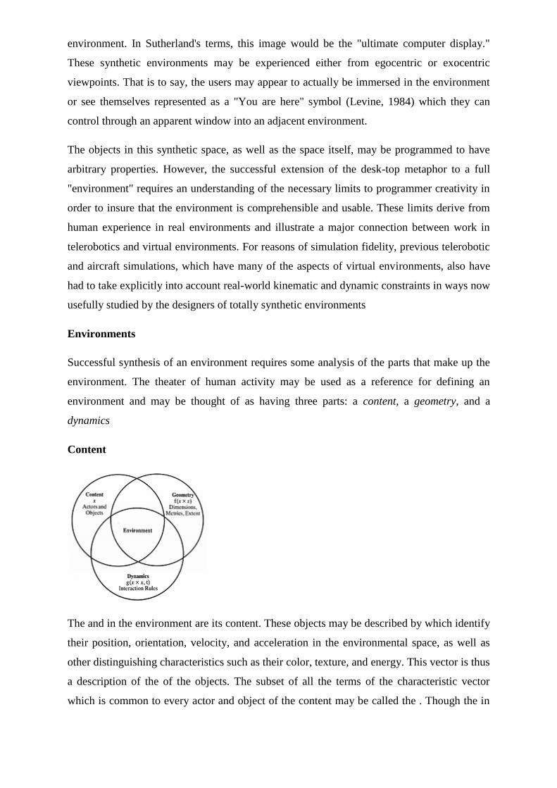
environment. In Sutherland's terms, this image would be the "ultimate computer display."
These synthetic environments may be experienced either from egocentric or exocentric
viewpoints. That is to say, the users may appear to actually be immersed in the environment
or see themselves represented as a "You are here" symbol (Levine, 1984) which they can
control through an apparent window into an adjacent environment.
The objects in this synthetic space, as well as the space itself, may be programmed to have
arbitrary properties. However, the successful extension of the desk-top metaphor to a full
"environment" requires an understanding of the necessary limits to programmer creativity in
order to insure that the environment is comprehensible and usable. These limits derive from
human experience in real environments and illustrate a major connection between work in
telerobotics and virtual environments. For reasons of simulation fidelity, previous telerobotic
and aircraft simulations, which have many of the aspects of virtual environments, also have
had to take explicitly into account real-world kinematic and dynamic constraints in ways now
usefully studied by the designers of totally synthetic environments
Environments
Successful synthesis of an environment requires some analysis of the parts that make up the
environment. The theater of human activity may be used as a reference for defining an
environment and may be thought of as having three parts: a content, a geometry, and a
dynamics
Content
The and in the environment are its content. These objects may be described by which identify
their position, orientation, velocity, and acceleration in the environmental space, as well as
other distinguishing characteristics such as their color, texture, and energy. This vector is thus
a description of the of the objects. The subset of all the terms of the characteristic vector
which is common to every actor and object of the content may be called the . Though the in
an environment may for some interactions be considered objects, they are distinct from
objects in that in addition to characteristics they have to initiate interactions with other
objects. The basis of these initiated interactions is the storage of energy or information within
the actors, and their ability to control the release of this stored information or energy after a
period of time. The is a distinct actor in the environment which provides a establishing the
frame of reference from which the environment may be constructed. All parts of the
environment that are exterior to the self may be considered the field of action. As an example,
the balls on a billiard table may be considered the content of the billiard table environment
and the cue ball controlled by the pool player maybe considered the . The additional energy
and information that makes the cue ball an actor is imparted to it by the cue controlled by the
pool player and his knowledge of game rules.
Geometry
The geometry is a description of the environmental field of action. It has , , and he
dimensionality refers to the number of independent descriptive terms needed to specify the
position vector for every element of the environment. The metrics are systems of rules that
may be applied to the position vector to establish an ordering of the contents and to establish
the concept of geodesic or the loci of minimal distance paths between points in the
environmental space. The extent of the environment refers to the range of possible values for
the elements of the position vector. The environmental space or field of action may be
defined as the cartesian product of all the elements of the position vector over their possible
ranges. An environmental trajectory is a time-history of an object through the environmental
space. Since kinematic constraints may preclude an object from traversing the space along
some paths, these constraints are also part of the environment's geometric description.
Dynamics
The dynamics of an environment are the among its contents describing their behaviour as
they exchange energy or information. Typical examples of specific dynamical rules may be
found in the differential equations of newtonian dynamics describing the responses of billiard
balls to impacts of the cue ball. For other environments, these rules also may take the form of
grammatical rules or even of look-up tables for pattern-match-triggered action rules. For
example, a syntactically correct command typed at a computer terminal can cause execution
of a program with specific parameters. In this case the meaning and information of the
command plays the role of the energy, and the resulting rate of change in the logical state of
the affected device, plays the role of acceleration.
rules of interaction
This analogy suggests the possibility of developing a semantic or informational mechanics in
which some measure of motion through the state space of an information processing device
may be related to the meaning or information content of the incoming messages. In such a
mechanics, the proportionality constant relating the change in motion to the message content
might be considered the or mass of the program. A principle difficulty in developing a useful
definition of "mass" from this analogy is that information processing devices typically can
react in radically different ways to slight variations in the surface structure of the content of
the input. Thus it is difficult to find a technique to analyze the input to establish equivalence
classes analogous to alternate distributions of substance with equivalent centres of mass. The
centre-of-gravity rule for calculating the centre of mass is an example of how various
apparently variant mass distributions may be reduced to a smaller number of equivalent
objects in a way simplifying consistent theoretical analysis as might be required for a
physical simulation on a computer.
semantic informational
The usefulness of analyzing environments into these abstract components, content, geometry,
and dynamics, primarily arises when designers search for ways to enhance operator
interaction with their simulations. For example, this analysis has organized the search for
graphical enhancements for pictorial displays of aircraft and spacecraft traffic (McGreevy
and Ellis, 1986; Ellis , 1987; Grunwald and Ellis, 1988, 1991, 1993). However, it also can
help organize theoretical thinking about what it means to be in an environment through
reflection concerning the experience of physical reality.
Sense of physical reality
Our sense of physical reality is a construction derived from the symbolic, geometric, and
dynamic information directly presented to our senses. But it is noteworthy that many of the
aspects of physical reality are only presented in incomplete, noisy form. For example, though
our eyes provide us only with a fleeting series of snapshots of only parts of objects present in
our visual world, through "knowledge" brought to perceptual analysis of our sensory input,
we accurately interpret these objects to continue to exist in their entirety). Similarly, our
goalseeking behaviour appears to filter noise by benefiting from internal dynamical models of
the objects we may track or control (Kalman, 1960; Kleinman , 1970). Accurate perception
consequently involves considerable knowledge about the possible structure of the world. This
knowledge is under constant recalibration based on error feedback. The role of error feedback
has been classically mathematically modeled during tracking behaviour (McRuer and Weir,
1969; Jex , 1966; Hess, 1987) and notably demonstrated in the behavioural plasticity of
visual-motor coordination
Thus, a large part of our sense of physical reality is a consequence of internal processing
rather than beingsomething that is developed only from the immediate sensory information
we receive. Our sensory and cognitive interpretive systems are predisposed to process
incoming information in ways that normally result in a correct interpretation of the external
environment, and in some cases they may be said to actually "resonate" with specific patterns
of input that are uniquely informative about our environment (Gibson, 1950; Heeger, 1989;
Koenderink and van Doorn, 1977; Regan and Beverley, 1979). These same constructive
processes are triggered by the displays used to present virtual environments. However, since
the incoming sensory information is mediated by the display technology, these constructive
processes will be triggered only to the extent the displays provide high perceptual fidelity.
Accordingly, virtual environments can come in different stages of completeness, which may
be usefully distinguished by their extent of what may be called "virtualization".
VIRTUAL TRACKING SYSTEM
The tracking devices are the main components for the VR systems. They interact with the
system‘s processing unit. This relays to the system the orientation of the user‘s point of view.
In systems which let a user to roam around within a physical space, the locality of the person
can be detected with the help of trackers, along with his direction and speed.
The various types of systems used for tracking utilized in VR systems. These are a follows:-
A six degree of freedom can be detected (6-DOF)
Orientation consists of a yaw of an object, roll andpitch.
These are nothing but the position of the objects within the x-y-z coordinates of a
space, however, it is also the orientation of the object.
These however emphasizes that when a user wears a HMD then as the user looks up and
down; left and right then the view also shifts. Whenever the user‘s head tilts, the angle of
gaze changes. The trackers on the HMD describe to the CPU where you are staring while the
right images are sent back to the screen of HMD.
All tracking system consists of a device that is capable of generating a signal and the signal is
detected by the sensor. It also controls the unit, which is involved in the process of the signal
and sends information to the CPU. Some systems ask you to add the component of the sensor
to the user (or the equipment of the user's). If this takes place, then you have to put the signal
emitters at certain levels in the nearby environment. Differences can be easily noticed in
some systems; with the emitters being worn by the users and covered by sensors, which are
attached to the environment. The signals emitted from emitters to different sensors can take
various shapes, including electromagnetic signals, optical signals, mechanical signals and
acoustic signals.
The Tracking devices have various merits and demerits:-
Electromagnetic tracking systems - Theycalculate magnetic fields generated by
bypassing an electric current simultaneously through 3 coiled wires. These wires are
set up in a perpendicular manner to one another. These small turns to be an
electromagnet. The system‘s sensors calculate how its magnetic field creates an
impact on the other coils. The measurement shows the orientation and direction of the
emitter. The responsiveness of an efficient electromagnetic tracking system is really
good. They level of latency is quite low. The drawback is that whatever that can
create a magnetic field, can come between the signals, which are sent to the sensors
Acoustic tracking systems - This tracking systemsenses and produces ultrasonic
sound waves to identify the orientation and position of a target. They calculate the
time taken for the ultrasonic sound to travel to a sensor. The sensors are usually kept
stable in the environment. The user puts on ultrasonic emitters. However, the
calculation of the orientation as well as position of the target depending on the time
on the time taken by the sound to hit the sensors is achieved by the system. Many
faults are shown by the acoustic tracking system. Sound passes by quite slowly, so the
update‘s rate on a target's position is naturally slow. The efficiency of the system can
be affected by the environment as the sound‘s speed through air often changes
depending on the humidity, temperature or the barometric pressure found in the
environment.
Optical tracking devices - These devices use light to calculate a target's orientation
along with position. The signal emitter typically includes a group of infrared LEDs.
The sensors consist of nothing but only cameras. These cameras can understand the
infrared light that has been emitted. The LEDs illuminates in a fashion known as
sequential pulses. The pulsed signals are recorded by the camera and then the
information is sent to the processing unit of the system. Data can be extrapolated by
this unit. This will estimate the position as well as the orientation of the target. The
upload rate of optical systems is quite fast which has in fact reduced the tenancy issue.
The demerits of the system are that the line of sight between an LED and camera can
be obscured, which interferes with the process of tracking. Infrared radiation or
ambient light are also different ways that can make a system useless.
Mechanical tracking systems – This tracking system is dependent on a physical link
between a fixed reference point and the target. One of the many examples is that
mechanical tracking system located in the VR field, which is indeed a BOOM display.
A BOOM display, an HMD, is attached on the rear of a mechanical arm consisting 2
points of articulation. The detection of the orientation and position of the system is
done through the arm. The rate of update is quite high with mechanical tracking
systems, but the demerit is that they limit range of motion for a user.
INTELLIGENT VR SOFTWARE SYSTEMS
Product designers and engineers require intelligent computer-aided design (CAD) tools that
enable them to quickly modify the shape, style, and functionality of a product concept. The
various technologies used throughout the design process must be both intuitive and easy to
use, with only a minimal amount of specialized training required. In addition, the design
information must be transformed into a format that can be seamlessly integrated into existing
CAD/CAE/CIM facilities. The proposed research program will continue current activities in
intelligent systems for geometric modeling, and explore how these innovative technologies
can be applied to interactive engineering design and analysis. The various hardware and
software solutions explored in this program will utilize emerging technologies such as
artificial neural networks, self-organizing feature maps, immersive virtual reality (VR), and
all-optical computing. The equipment and laboratory infrastructure necessary to undertake
this work has been acquired through a successful collaborative CFI grant proposal entitled ―A
facility for modeling, visualization, and virtual reality based interaction‖ [Investigators: Patel
et. al. (UWO)].
OBJECTIVES
The long-term objective of this research program is to develop the next generation of
automated design tools that allow the end-user to rapidly modify the product concept through
human-friendly reverse engineering, CAD, virtual reality (VR), and rapid prototyping (RP)
tools. Important prerequisites for automated design are robust technologies that reliably
generate surface and solid models from acquired spatial data and user instructions, and
seamlessly integrate this information into the overall product design process.
(i) Develop algorithms to adaptively reconstruct complex free-form surfaces from both
organized and scattered coordinate data,
(ii) Investigate how deformable self-organizing feature maps can be used to register and
recognize free-form shapes, and
(iii) Explore how spherical self-organizing feature maps can generate geometric shapes that
represent hidden patterns in high-dimensional, large volume numeric data sets and develop
methods to represent high-dimensional data in immersive VR environments.
The research program will investigate several ways of adding intelligence to the design
process by automating reverse engineering and geometric modeling in CAD applications, and
enabling mechanical designers to visualize patterns in numeric data-bases for enhanced
engineering analysis. The following topics will be investigated.
(i) Adaptive Surface Reconstruction using a Neural Network Approach
Many computer graphics and CAD applications require mathematical models to be generated
from measured coordinate data. High-resolution non-contact range sensors typically acquire
100,000 to 500,000 coordinate data points for shape measurement [4]. By using a
mathematical surface model, the same complex shape can be economically represented by as
few as 50-500 parameters. Parametric representations are preferred in engineering design
because they permit simple object-shape modification by changing only a small number of
parameters, such as control points, knot values, or weight values. Complex free-form shapes
can be created by joining together several low-order surface patches, and adjusting the
control parameters such that the constituent patches meet seamlessly at their common
boundaries. Artificial neural networks have been proposed as one method of dynamically
fitting surfaces to spatial data but most neural networks produce solutions that are not easily
transferable to commercial CAD software [8].
An adaptive surface reconstruction technique has been developed that generates a smooth
surface from adjacent Bézier patches [12]. The approach utilizes a functional neural network
[5], called the Bernstein Basis Function (BBF) network, which performs a weighted
summation of Bernstein polynomial basis functions. The number of basis neurons is related
to the degree of the Bernstein polynomials and equivalent to the number of control
parameters. Free-form surfaces are reconstructed by simultaneously updating networks that
correspond to the separate patches. A smooth transition between adjacent Bézier surface
patches is achieved by imposing positional and tangential continuity constraints on the
weights during the adaptation process. The final weights of the various networks correspond
to the control points of the stitched Bézier surface, and can therefore be used directly in many
commercial CAD packages. Future research will investigate how to determine the optimal
number of neurons for a particular data set. One approach to be studied involves iteratively
growing and shrinking network size. This process would correspond to an increase and
decrease in the order of the Bernstein basis functions. In addition, work must still be done to
automatically stitch multiple patches for complex surfaces and fit the parametric surfaces to
scattered data.
Many algorithms for automated surface fitting [2,4] require prior knowledge of the
connectivity between sampled points prior to parametric surface fitting. This task becomes
increasingly difficult if the capture of the coordinate data is unorganized or scattered. Often
the algorithms for scattered data interpolation attempt to explicitly compute the connections
between neighbouring data points prior to constructing a polygon mesh. A majority of the
techniques used to compute connectivity require a dense data set to prevent gaps and holes
from forming on the reconstructed surface within under-sampled areas. The gaps and holes
can significantly change the topology for the generated surface. The algorithm proposed by
[10] is based on surface reconstruction using normal vectors obtained from tangent planes
defined at sample points. The method of reconstruction thus depends on the estimation of the
normal vectors from the data points and the order in which orientation propagates. Although
the technique is effective for a range of data sets, it is very complex and computationally
intensive.
An alternative approach to solving the problem of scattered data parameterization is to
assume a predefined 2D-mesh with the desired connectivity between neighbouring vertices or
nodes. An interpolation algorithm is then used to iteratively adjust the nodes in the mesh in
order to match the coordinate data set. In this way, the interpolation algorithm learns the
surface coordinates given the node connectivity [20]. Recent studies showed how a two-
dimensional self-organizing feature map (SOFM) can establish an order within the scattered
data and, thereby, provide connectivity information within the data by constructing a polygon
mesh with topologically connected quadrilateral elements. The SOFM learning algorithm
iteratively adjusts the node, or cluster unit, weights such that neighbouring units in the 2D
map are connected nodes in the ―best fit‖ polygon mesh. The mesh can be used directly as a
tessellated representation for computer graphic applications or as a robust method to
parameterize the data prior to Bézier, B-spline or NURB fitting [1]. The major advantage of
using a predetermined grid topology such as the SOFM is that no unexpected gaps or holes
will be generated on the reconstructed surface, even if the input data is sparse. This
preliminary work is promising but requires more in-depth study.
(ii) Recognition of Free-Form Shapes using Deformable Self-Organizing Feature Maps
The recognition of free-form objects is a difficult task in a variety of reverse engineering and
intelligent CAD applications. The general steps involved in an object recognition process are
data acquisition, surface representation, feature extraction and feature matching
(correspondence and transformation). The performance of the matching process largely
depends on surface representation and the features extracted. Most recognition systems can
handle polyhedral objects that are defined by a set of primitives such as vertices, edges, or
planar faces. However, free-form shapes have curved surfaces and often lack identifiable
markers such as corners or sharp discontinuities. A few of the methods used to generate
object representations have been discussed [2,3]. However, most of these methods do not
perform well with smooth free-form shapes because they require information on the topology
of the shape.
For matching purposes, the object may be represented by an abstract form that encapsulates
key geometry and topology information of 3D objects, or, it may represent information
content concealed in numeric data. The extended Gaussian image representation (EGI) and
complex extended Gaussian image (CEGI) [11] for representing objects are examples of
methods that represent the object as a spherical map in an independent coordinate system.
Another more recent technique [9] surrounds the object by a discrete mesh and then deforms
it to faithfully represent the shape of the object. A mapping is defined between the mesh and
a standard spherical mesh. A surface curvature measure is computed at each node on the
spherical mesh. The primary difficulty in generating such representations is the unstructured,
scattered nature of coordinate data acquired from range data or CAD surface models.
Essentially, there is no prior knowledge about the connectivity between sampled points.
In the proposed research, a spherical self-organizing feature map will be fitted to the
coordinate data of the free-form shape such that it closely represents the shape of the object.
The method is similar to the adaptive deformable surfaces proposed by [14,17]. Due to the
self-organizing capability of the map a topological order is established within the scattered
data by exploiting local similarities, thereby providing connectivity information about the
coordinate points. The weights of the cluster units form prototypical representations of the
coordinates in the data space. A unique feature of the spherical SOFM representation is that
the connected units, or nodes, represent a structured tessellated model of the free-form shape
with triangular or quadrilateral facets that retain key geometric and topological attributes of
the free-form shape.
Often, the surface representations will have inadequate features or the absence of identifiable
markers such as corners or sharp discontinuities that can be used for recognition purposes.
Once the spherical SOFM develops a topological order to the measured coordinate data, such
that connected nodes on the spherical map represent neighboring points on the object surface,
then curvature features can be extracted at each node of the SOFM. The feature vector is
computed using a simple function that relates the node‘s positional vector to each of its
neighbouring nodes, within a circular area of one unit radius, in the SOFM. The feature
vectors are used to establish a correspondence between the spherical map generated by an
unknown free-form shape and maps of all the reference models. Any two free-form shapes
can be matched for recognition purposes by registering the spherical SOFMs and determining
the minimum registration error. This approach enables the unknown object to be in an
arbitrary orientation similar to the method described by [9].
(iii) Visualization of Randomly Ordered Numeric Data Sets using Spherical SOFMs
Interactive data visualization techniques attempt to transform large quantities of high-
dimensional numeric or symbolic data into colorized or geometric patterns that enable
engineers to observe system behaviour in new informative ways [6]. In high-dimensional data
sets, each input is an N-dimensional feature vector that represents numerous independent and
interdependent attributes of the data. Each dimension in the input feature vector influences
the observer‘s interpretation of the embedded information. By assigning a 3D form to the
numeric data, the information is correlated for enhanced interpretation. Geometric attributes,
such as shape and size, and color-coding can be used as visual cues of data association [6,7].
Variations in these forms will reflect the relationships between seemingly unrelated data
vectors, thereby reflecting information content.
Since engineers and product designers can relate to changes in 3D shapes more easily than
―seemingly random‖ strings of numbers, high-dimensional data visualization methods are
now shifting away from two-dimensional graphic plots to volumetric displays. In the glyph-
based visualization method [16] a glyph or graphical object is used to visualize relationships
among text documents. Matching terms are mapped to representative shapes and
similarity/differences among documents are viewed in the form of variations in the resulting
shapes. Documents with similar themes will have almost the same general shape. A variation
on this method is a visualization algorithm based on shape interpolation between shape
implicit functions [18]. These methods are dependent on the shape primitives used and
difficulty arises in interpreting the shapes if the variation in the intermediate shapes is not
significant.
The use of the self-organizing feature map (SOFM) has also been explored as a visualization
tool [7,19] due to its ability to internally order and correlate data without making any
assumptions on the underlying relationships present in the data. The data is reduced to
prototypical units and projected onto a uniform grid. Data association is visualized in terms
of the relative positions of the units. However, a majority of the work using the SOFM for
visualization purposes has been directed towards projecting the high-dimensional data onto a
―flat space‖. The proposed research will explore how a deformable spherical self-organizing
feature map (SOFM) [13] develops an internal ordered representation of high-dimensional
numeric data and represents the constituent data vectors as a three-dimensional form.
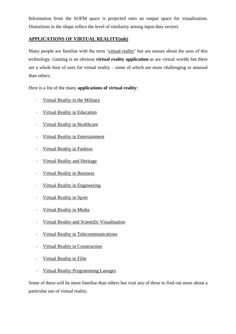
Information from the SOFM space is projected onto an output space for visualization.
Distortions in the shape reflect the level of similarity among input data vectors.
APPLICATIONS OF VIRTUAL REALITY(mh)
Many people are familiar with the term ‗virtual reality‘ but are unsure about the uses of this
technology. Gaming is an obvious virtual reality application as are virtual worlds but there
are a whole host of uses for virtual reality – some of which are more challenging or unusual
than others.
Here is a list of the many applications of virtual reality:
Virtual Reality in the Military
Virtual Reality in Education
Virtual Reality in Healthcare
Virtual Reality in Entertainment
Virtual Reality in Fashion
Virtual Reality and Heritage
Virtual Reality in Business
Virtual Reality in Engineering
Virtual Reality in Sport
Virtual Reality in Media
Virtual Reality and Scientific Visualisation
Virtual Reality in Telecommunications
Virtual Reality in Construction
Virtual Reality in Film
Virtual Reality Programming Lanuges
Some of these will be more familiar than others but visit any of these to find out more about a
particular use of virtual reality.
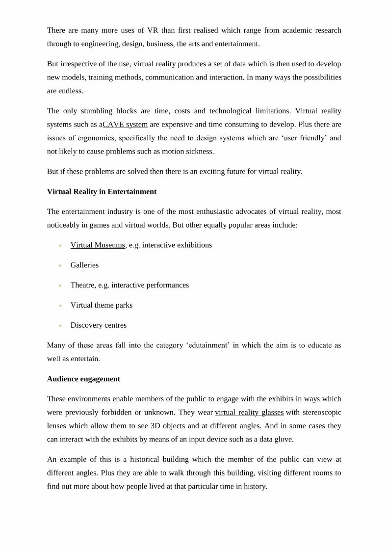
There are many more uses of VR than first realised which range from academic research
through to engineering, design, business, the arts and entertainment.
But irrespective of the use, virtual reality produces a set of data which is then used to develop
new models, training methods, communication and interaction. In many ways the possibilities
are endless.
The only stumbling blocks are time, costs and technological limitations. Virtual reality
systems such as aCAVE system are expensive and time consuming to develop. Plus there are
issues of ergonomics, specifically the need to design systems which are ‗user friendly‘ and
not likely to cause problems such as motion sickness.
But if these problems are solved then there is an exciting future for virtual reality.
Virtual Reality in Entertainment
The entertainment industry is one of the most enthusiastic advocates of virtual reality, most
noticeably in games and virtual worlds. But other equally popular areas include:
Virtual Museums, e.g. interactive exhibitions
Galleries
Theatre, e.g. interactive performances
Virtual theme parks
Discovery centres
Many of these areas fall into the category ‗edutainment‘ in which the aim is to educate as
well as entertain.
Audience engagement
These environments enable members of the public to engage with the exhibits in ways which
were previously forbidden or unknown. They wear virtual reality glasses with stereoscopic
lenses which allow them to see 3D objects and at different angles. And in some cases they
can interact with the exhibits by means of an input device such as a data glove.
An example of this is a historical building which the member of the public can view at
different angles. Plus they are able to walk through this building, visiting different rooms to
find out more about how people lived at that particular time in history.
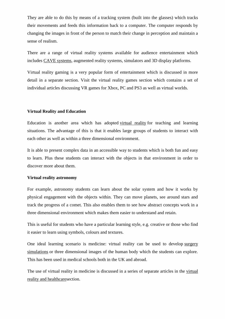
They are able to do this by means of a tracking system (built into the glasses) which tracks
their movements and feeds this information back to a computer. The computer responds by
changing the images in front of the person to match their change in perception and maintain a
sense of realism.
There are a range of virtual reality systems available for audience entertainment which
includes CAVE systems, augmented reality systems, simulators and 3D display platforms.
Virtual reality gaming is a very popular form of entertainment which is discussed in more
detail in a separate section. Visit the virtual reality games section which contains a set of
individual articles discussing VR games for Xbox, PC and PS3 as well as virtual worlds.
Virtual Reality and Education
Education is another area which has adopted virtual reality for teaching and learning
situations. The advantage of this is that it enables large groups of students to interact with
each other as well as within a three dimensional environment.
It is able to present complex data in an accessible way to students which is both fun and easy
to learn. Plus these students can interact with the objects in that environment in order to
discover more about them.
Virtual reality astronomy
For example, astronomy students can learn about the solar system and how it works by
physical engagement with the objects within. They can move planets, see around stars and
track the progress of a comet. This also enables them to see how abstract concepts work in a
three dimensional environment which makes them easier to understand and retain.
This is useful for students who have a particular learning style, e.g. creative or those who find
it easier to learn using symbols, colours and textures.
One ideal learning scenario is medicine: virtual reality can be used to develop surgery
simulations or three dimensional images of the human body which the students can explore.
This has been used in medical schools both in the UK and abroad.
The use of virtual reality in medicine is discussed in a series of separate articles in the virtual
reality and healthcaresection.
Virtual reality and tech-savvy children
Then there is the fact that children today are familiar with all forms of technology and use
these at school as well as at home. They have grown up with technology from a very early
age and unlike adults, do not have any fear or hesitation in using it.
Plus we live in a technological society. So it makes sense to implement virtual reality as one
of several forms of technology in order to educate tomorrow‗s technological elite. Education
has moved on from books, pencils and pens to the use of interactive technologies to help
impart knowledge and understanding.
Virtual Reality in Business
Virtual reality is being used in a number of ways by the business community which include:
Virtual tours of a business environment
Training of new employees
A 360 view of a product
Many businesses have embraced virtual reality as a cost effective way of developing a
product or service. For example it enables them to test a prototype without having to develop
several versions of this which can be time consuming and expensive.
Plus it is a good way of detecting design problems at an early stage which can then be dealt
with sooner rather than later.
Business benefits
For some businesses, fully immersive virtual reality a la CAVE system is the way forward.
They like the fact that they can use this to test drive a product in the early stages of
development but without any additional costs (or risks) to themselves.
This is particularly useful for companies who produce dangerous or potentially harmful
products which need to be evaluated before use. They can test their product within a virtual
environment but at no risk to themselves or their employees. And virtual reality technology
has advanced to the stage where it has a high degree of realism and efficiency.
Some companies use virtual reality to help with data analysis and forecasting trends in order
to gain an edge over their competitors. One example of this is a system developed by
researchers at the University of Warwick which is designed to help businesses gain a greater
understanding of their data.
Virtual worlds for business
Another use is virtual worlds: there are companies who use virtual worlds as a means of
holding meetings with people who are based in various locations. This is often a low cost
solution to the problem of communication with large numbers of employees in remote
locations.
Virtual environments are also used for training courses and role playing scenarios.
Virtual Reality in Engineering
Virtual reality engineering includes the use of 3D modelling tools and visualisation
techniques as part of the design process. This technology enables engineers to view their
project in 3D and gain a greater understanding of how it works. Plus they can spot any flaws
or potential risks before implementation.
This also allows the design team to observe their project within a safe environment and make
changes as and where necessary. This saves both time and money.
What is important is the ability of virtual reality to depict fine grained details of an
engineering product to maintain the illusion. This means high end graphics, video with a fast
refresh rate and realistic sound and movement.
Virtual reality and the design cycle
In some cases, virtual reality can be used from the start of the design lifecycle, e.g. the initial
concept through to the build and implementation stages. This is reviewed at stages to check
for faults, structural weaknesses and other design issues.
Virtual reality and rail construction
Virtual reality engineering is employed by Balfour Beatty Rail, a rail infrastructure contractor
who includes this as part of their design process. It is used for planning, prototyping and
construction purposes, and helps with project realisation.
Virtual reality and car design
Car manufacturers use virtual reality for prototyping purposes during the design process. This
enables them to produce several versions which are then tested and changed as per the results.
This removes the need to build a physical prototype and speeds up the development stage.
The result is a cost effective streamlined process.
An example of this can be seen at the JLR Virtual Reality Centre in the UK. This is state of
the art virtual reality - both semi-immersive and CAVE systems - with advanced tracking and
projection facilities which is used to help design the next generation of Land Rovers.
QUESTIONS
1. Define virtual reality in multimedia?
2. What are intelligent systems?
3. What are VR systems?
4. Describe the environment of VR technology?
5. What are the applications of VR technology?

9, Km Milestone, NH-65, Kaithal - 136027, HaryanaWebsite: www.niilmuniversity.in
“The lesson content has been compiled from various sources in public domain including but not limited to the internet for the convenience of the users. The university has no proprietary right on the same.”
Related Documents