MultiHop Radio Configuration Tool Rev. B 9/25/2013 150473

Welcome message from author
This document is posted to help you gain knowledge. Please leave a comment to let me know what you think about it! Share it to your friends and learn new things together.
Transcript
MultiHop Radio Configuration ToolRev. B 9/25/2013150473
Contents1 MultiHop Configuration Tool ........................................................................................... 3
1.1 Installation ...............................................................................................................................32 Network View Screen ..................................................................................................... 53 Register View Screen ......................................................................................................74 Device Config Screen ...................................................................................................... 8
4.1 Device Parameter Screen ........................................................................................................... 84.1.1 Reading Configuration Data from the MultiHop Radios .......................................................... 84.1.2 I/O Parameters .............................................................................................................. 84.1.3 Device Parameters .........................................................................................................194.1.4 Restore Device ............................................................................................................. 23
4.2 Register Aliasing .................................................................................................................... 234.3 Save/Load Screen ................................................................................................................... 244.4 Reprogram Device Screen ........................................................................................................ 264.5 AT Mode Screen ...................................................................................................................... 28
5 Master Mode Screen ..................................................................................................... 296 Setup Screen ................................................................................................................ 317 Additional Information ................................................................................................. 33
7.1 Communication Mode ..............................................................................................................337.2 Unknown Device .................................................................................................................... 34
Contents
2 Rev. B
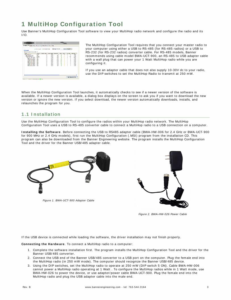
1 MultiHop Configuration ToolUse Banner’s MultiHop Configuration Tool software to view your MultiHop radio network and configure the radio and itsI/O.
The MultiHop Configuration Tool requires that you connect your master radio toyour computer using either a USB to RS-485 (for RS-485 radios) or a USB toRS-232 (for RS-232 radios) converter cable. For RS-485 models, Bannerrecommends using cable model BWA-UCT-900, an RS-485 to USB adapter cablewith a wall plug that can power your 1 Watt MultiHop radio while you areconfiguring it.
If you use an adapter cable that does not also supply 10-30V dc to your radio,use the DIP switches to set the MultiHop Radio to transmit at 250 mW.
When the MultiHop Configuration Tool launches, it automatically checks to see if a newer version of the software isavailable. If a newer version is available, a dialog box displays on the screen to ask you if you want to download the newversion or ignore the new version. If you select download, the newer version automatically downloads, installs, andrelaunches the program for you.
1.1 InstallationUse the MultiHop Configuration Tool to configure the radios within your MultiHop radio network. The MultiHopConfiguration Tool uses a USB to RS-485 converter cable to connect a MultiHop radio to a USB connection on a computer.
Installing the Software. Before connecting the USB to RS485 adapter cable (BWA-HW-006 for 2.4 GHz or BWA-UCT-900for 900 MHz or 2.4 GHz models), first run the MultiHop Configuration (.MSI) program from the installation CD. Thisprogram can also be downloaded from the Banner Engineering website. The program installs the MultiHop ConfigurationTool and the driver for the Banner USB/485 adapter cable.
Figure 1. BWA-UCT-900 Adapter Cable
Figure 2. BWA-HW-026 Power Cable
If the USB device is connected while loading the software, the driver installation may not finish properly.
Connecting the Hardware. To connect a MultiHop radio to a computer:
1. Complete the software installation first. The program installs the MultiHop Configuration Tool and the driver for theBanner USB/485 converter.
2. Connect the USB end of the Banner USB/485 converter to a USB port on the computer. Plug the female end intothe MultiHop radio (in 250 mW mode). The computer should recognize the Banner USB/485 device.
3. Using the DIP switches, set the MultiHop radio to operate at 250 mW (DIP switch 5 ON). Cable BWA-HW-006cannot power a MultiHop radio operating at 1 Watt . To configure the MultiHop radios while in 1 Watt mode, useBWA-HW-026 to power the device, or use adapter/power cable BWA-UCT-900. Plug the female end into theMultiHop radio and plug the USB adapter cable into the male end.
Rev. B www.bannerengineering.com - tel: 763-544-3164 3
4. Connect a Banner MultiHop radio to the Euro-style connect end of the USB/485 converter. The MultiHop radiopowers up.1 When using a third-party USB/485 converter, manually wire the communication and powerconnections. Refer to Banner’s MultiHop radio datasheet for the wiring pinout configurations.
5. Launch the MultiHop Configuration Tool. Select the USB from the pulldown list.6. Use the Setup tab to select a USB port and baud rate if the SureCross MultiHop radio is not automatically
detected. The factory default baud rate is 19.2k, 1 stop bit, no parity.
For most of the MultiHop Configuration Tool screens, a grayed box represents a parameter read from the device and awhite box represents parameters entered by the user.
1 The MultiHop radio will not power up until the computer recognizes and configures the USB port. After plugging the USB/485converter into the computer’s USB port, wait about 10 seconds for the radio to be powered (LED 1 solid green).
MultiHop Radio Configuration Tool
4 www.bannerengineering.com - tel: 763-544-3164 Rev. B
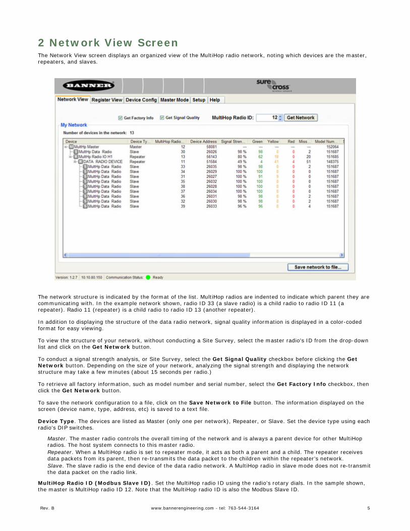
2 Network View ScreenThe Network View screen displays an organized view of the MultiHop radio network, noting which devices are the master,repeaters, and slaves.
The network structure is indicated by the format of the list. MultiHop radios are indented to indicate which parent they arecommunicating with. In the example network shown, radio ID 33 (a slave radio) is a child radio to radio ID 11 (arepeater). Radio 11 (repeater) is a child radio to radio ID 13 (another repeater).
In addition to displaying the structure of the data radio network, signal quality information is displayed in a color-codedformat for easy viewing.
To view the structure of your network, without conducting a Site Survey, select the master radio's ID from the drop-downlist and click on the Get Network button.
To conduct a signal strength analysis, or Site Survey, select the Get Signal Quality checkbox before clicking the GetNetwork button. Depending on the size of your network, analyzing the signal strength and displaying the networkstructure may take a few minutes (about 15 seconds per radio.)
To retrieve all factory information, such as model number and serial number, select the Get Factory Info checkbox, thenclick the Get Network button.
To save the network configuration to a file, click on the Save Network to File button. The information displayed on thescreen (device name, type, address, etc) is saved to a text file.
Device Type. The devices are listed as Master (only one per network), Repeater, or Slave. Set the device type using eachradio's DIP switches.
Master. The master radio controls the overall timing of the network and is always a parent device for other MultiHopradios. The host system connects to this master radio.Repeater. When a MultiHop radio is set to repeater mode, it acts as both a parent and a child. The repeater receivesdata packets from its parent, then re-transmits the data packet to the children within the repeater’s network.Slave. The slave radio is the end device of the data radio network. A MultiHop radio in slave mode does not re-transmitthe data packet on the radio link.
MultiHop Radio ID (Modbus Slave ID). Set the MultiHop radio ID using the radio's rotary dials. In the sample shown,the master is MultiHop radio ID 12. Note that the MultiHop radio ID is also the Modbus Slave ID.
Rev. B www.bannerengineering.com - tel: 763-544-3164 5
Device Address. The device address (DADR) is a unique number based on the device's serial number and is set by thefactory. This address displays as part of the RUN menu's auto-loop display on the device's LCD screen while the radio isoperating.
Signal Strength. The master radio conducts a site survey with all radios within the MultiHop radio network and displaysthe number of packets successfully transmitted at the various signal strengths represented by the "green," "yellow," and"red" delineations. "Green" refers to a strong radio signal, "yellow" is a good radio signal, and "red" is a marginal radiosignal. "Miss" represents the number of packets not received on their first transmission.
Model Number. The model number is a 6-digit number used by the manufacturer to identify the device model of theradio.
Serial Number. The serial number is a 6-digit, unique number that identifies that specific radio. No other radio will beassigned this number. Each SureCross radio uses its serial number to generate the device address that displays on thisNetwork View screen and the radio's LCD.
Firmware and EEPROM Updates. These parameters are set at the factory. You may be asked for this information if youcall Banner Engineering for technical support. To update these programs, obtain the newest versions from the factory,then use the Bootloader Screen to copy these files to your radio.
RF Firmware. Version number for installed firmware of the radio microprocessor.RF EEPROM. Version number for installed EEPROM of the radio microprocessor.LCD Firmware. Version number for installed firmware of the LCD microprocessor.LCD EEPROM. Version number for installed EEPROM of the LCD microprocessor.
MultiHop Radio Configuration Tool
6 www.bannerengineering.com - tel: 763-544-3164 Rev. B
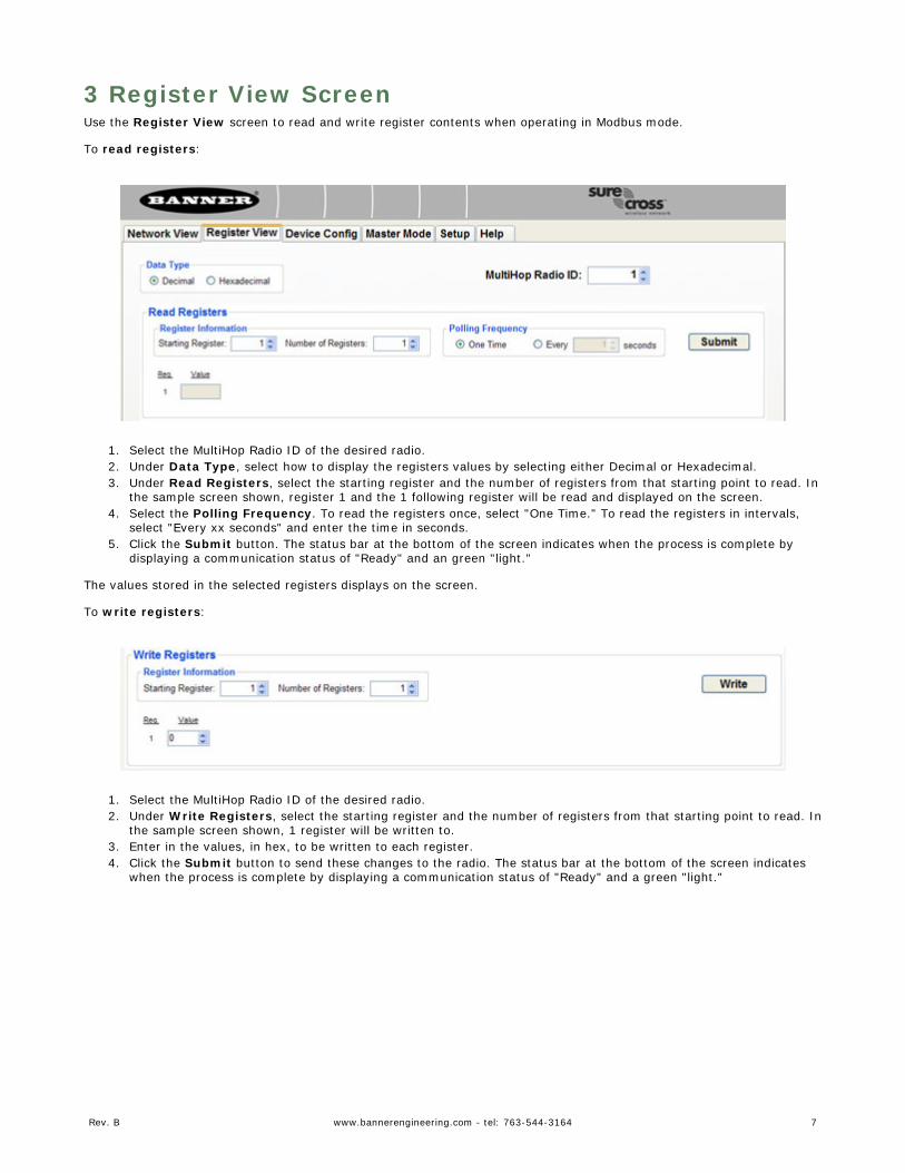
3 Register View ScreenUse the Register View screen to read and write register contents when operating in Modbus mode.
To read registers:
1. Select the MultiHop Radio ID of the desired radio.2. Under Data Type, select how to display the registers values by selecting either Decimal or Hexadecimal.3. Under Read Registers, select the starting register and the number of registers from that starting point to read. In
the sample screen shown, register 1 and the 1 following register will be read and displayed on the screen.4. Select the Polling Frequency. To read the registers once, select "One Time." To read the registers in intervals,
select "Every xx seconds" and enter the time in seconds.5. Click the Submit button. The status bar at the bottom of the screen indicates when the process is complete by
displaying a communication status of "Ready" and an green "light."
The values stored in the selected registers displays on the screen.
To write registers:
1. Select the MultiHop Radio ID of the desired radio.2. Under Write Registers, select the starting register and the number of registers from that starting point to read. In
the sample screen shown, 1 register will be written to.3. Enter in the values, in hex, to be written to each register.4. Click the Submit button to send these changes to the radio. The status bar at the bottom of the screen indicates
when the process is complete by displaying a communication status of "Ready" and a green "light."
Rev. B www.bannerengineering.com - tel: 763-544-3164 7
4 Device Config Screen4.1 Device Parameter Screen
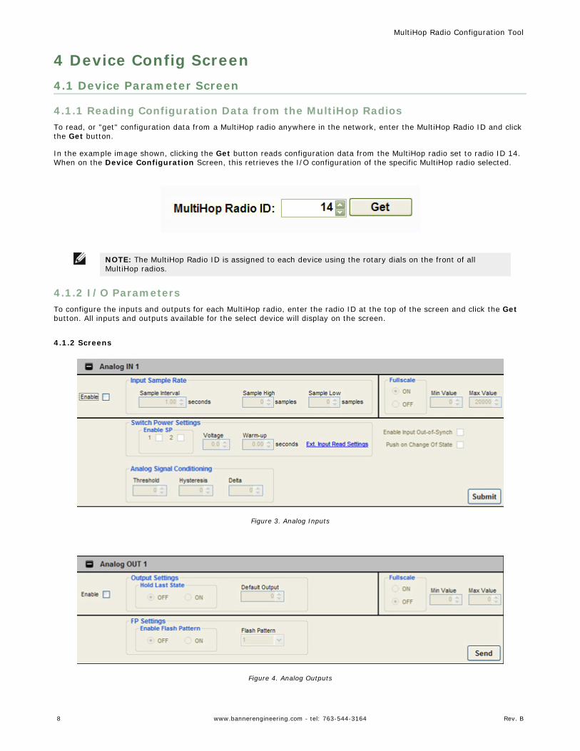
4.1.1 Reading Configuration Data from the MultiHop RadiosTo read, or "get" configuration data from a MultiHop radio anywhere in the network, enter the MultiHop Radio ID and clickthe Get button.
In the example image shown, clicking the Get button reads configuration data from the MultiHop radio set to radio ID 14.When on the Device Configuration Screen, this retrieves the I/O configuration of the specific MultiHop radio selected.
NOTE: The MultiHop Radio ID is assigned to each device using the rotary dials on the front of allMultiHop radios.
4.1.2 I/O ParametersTo configure the inputs and outputs for each MultiHop radio, enter the radio ID at the top of the screen and click the Getbutton. All inputs and outputs available for the select device will display on the screen.
4.1.2 Screens
Figure 3. Analog Inputs
Figure 4. Analog Outputs
MultiHop Radio Configuration Tool
8 www.bannerengineering.com - tel: 763-544-3164 Rev. B
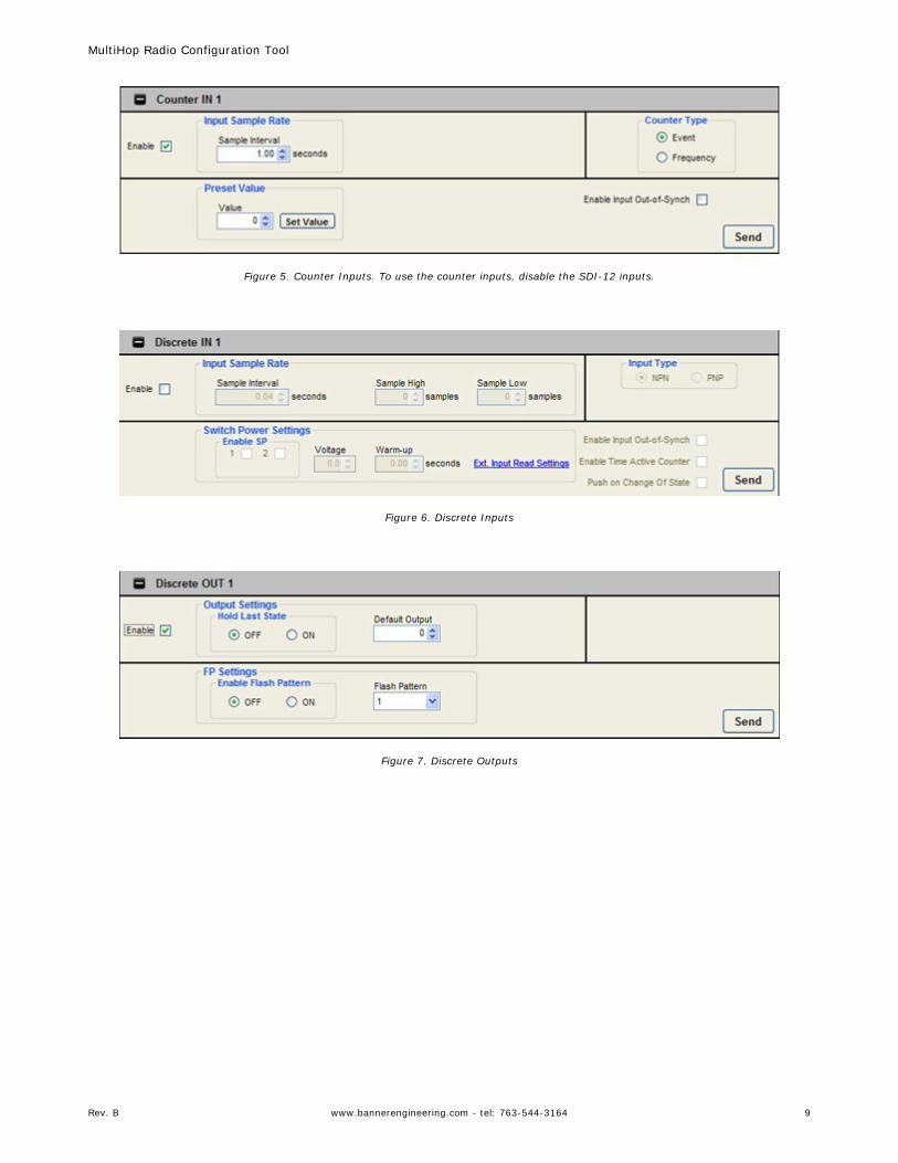
Figure 5. Counter Inputs. To use the counter inputs, disable the SDI-12 inputs.
Figure 6. Discrete Inputs
Figure 7. Discrete Outputs
MultiHop Radio Configuration Tool
Rev. B www.bannerengineering.com - tel: 763-544-3164 9
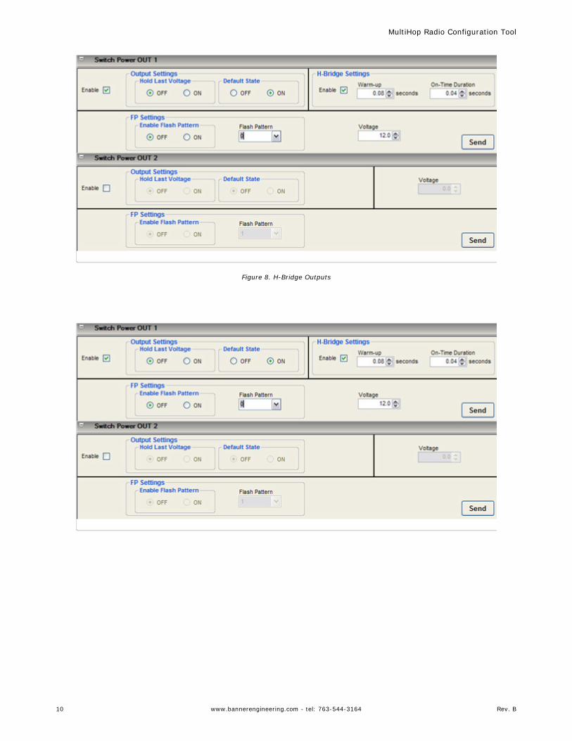
Figure 8. H-Bridge Outputs
MultiHop Radio Configuration Tool
10 www.bannerengineering.com - tel: 763-544-3164 Rev. B
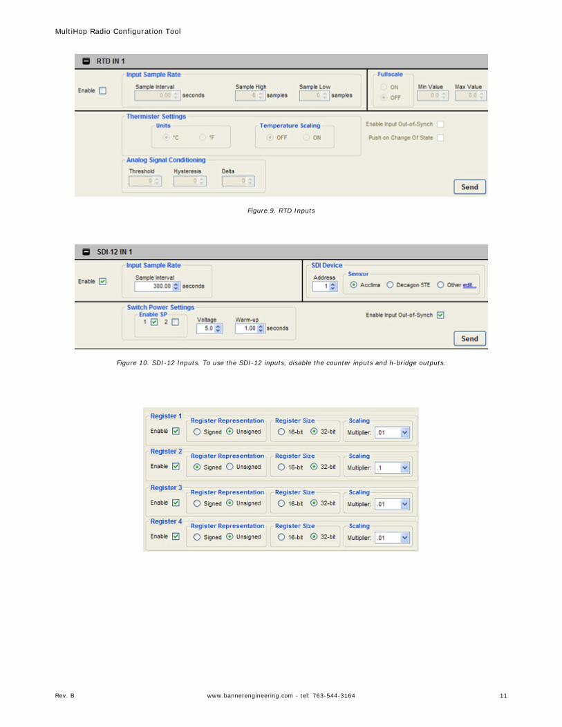
Figure 9. RTD Inputs
Figure 10. SDI-12 Inputs. To use the SDI-12 inputs, disable the counter inputs and h-bridge outputs.
MultiHop Radio Configuration Tool
Rev. B www.bannerengineering.com - tel: 763-544-3164 11
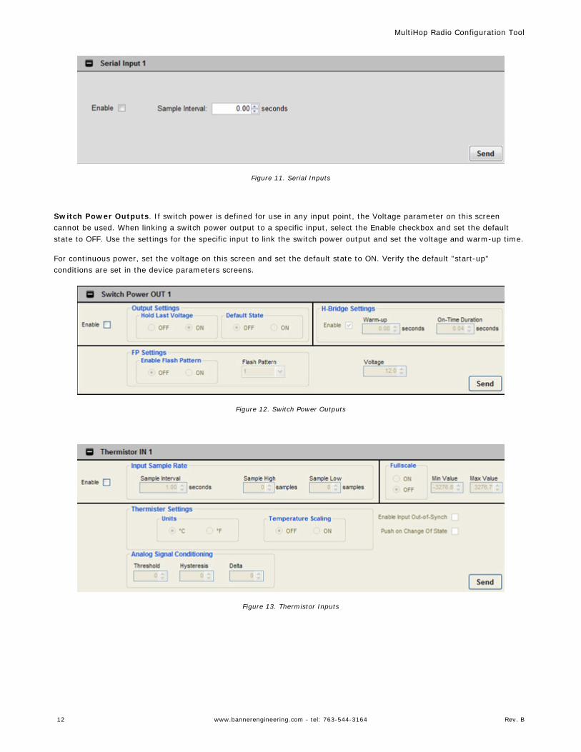
Figure 11. Serial Inputs
Switch Power Outputs. If switch power is defined for use in any input point, the Voltage parameter on this screencannot be used. When linking a switch power output to a specific input, select the Enable checkbox and set the defaultstate to OFF. Use the settings for the specific input to link the switch power output and set the voltage and warm-up time.
For continuous power, set the voltage on this screen and set the default state to ON. Verify the default "start-up"conditions are set in the device parameters screens.
Figure 12. Switch Power Outputs
Figure 13. Thermistor Inputs
MultiHop Radio Configuration Tool
12 www.bannerengineering.com - tel: 763-544-3164 Rev. B
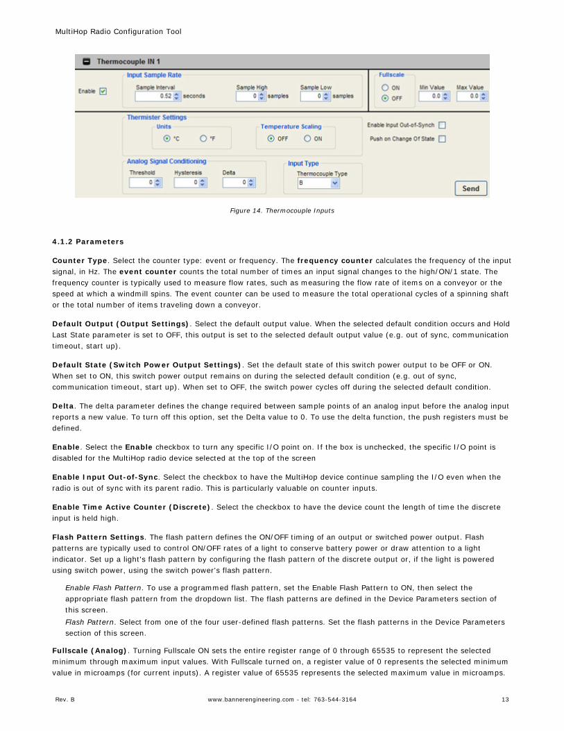
Figure 14. Thermocouple Inputs
4.1.2 Parameters
Counter Type. Select the counter type: event or frequency. The frequency counter calculates the frequency of the inputsignal, in Hz. The event counter counts the total number of times an input signal changes to the high/ON/1 state. Thefrequency counter is typically used to measure flow rates, such as measuring the flow rate of items on a conveyor or thespeed at which a windmill spins. The event counter can be used to measure the total operational cycles of a spinning shaftor the total number of items traveling down a conveyor.
Default Output (Output Settings). Select the default output value. When the selected default condition occurs and HoldLast State parameter is set to OFF, this output is set to the selected default output value (e.g. out of sync, communicationtimeout, start up).
Default State (Switch Power Output Settings). Set the default state of this switch power output to be OFF or ON.When set to ON, this switch power output remains on during the selected default condition (e.g. out of sync,communication timeout, start up). When set to OFF, the switch power cycles off during the selected default condition.
Delta. The delta parameter defines the change required between sample points of an analog input before the analog inputreports a new value. To turn off this option, set the Delta value to 0. To use the delta function, the push registers must bedefined.
Enable. Select the Enable checkbox to turn any specific I/O point on. If the box is unchecked, the specific I/O point isdisabled for the MultiHop radio device selected at the top of the screen
Enable Input Out-of-Sync. Select the checkbox to have the MultiHop device continue sampling the I/O even when theradio is out of sync with its parent radio. This is particularly valuable on counter inputs.
Enable Time Active Counter (Discrete). Select the checkbox to have the device count the length of time the discreteinput is held high.
Flash Pattern Settings. The flash pattern defines the ON/OFF timing of an output or switched power output. Flashpatterns are typically used to control ON/OFF rates of a light to conserve battery power or draw attention to a lightindicator. Set up a light's flash pattern by configuring the flash pattern of the discrete output or, if the light is poweredusing switch power, using the switch power's flash pattern.
Enable Flash Pattern. To use a programmed flash pattern, set the Enable Flash Pattern to ON, then select theappropriate flash pattern from the dropdown list. The flash patterns are defined in the Device Parameters section ofthis screen.Flash Pattern. Select from one of the four user-defined flash patterns. Set the flash patterns in the Device Parameterssection of this screen.
Fullscale (Analog). Turning Fullscale ON sets the entire register range of 0 through 65535 to represent the selectedminimum through maximum input values. With Fullscale turned on, a register value of 0 represents the selected minimumvalue in microamps (for current inputs). A register value of 65535 represents the selected maximum value in microamps.
MultiHop Radio Configuration Tool
Rev. B www.bannerengineering.com - tel: 763-544-3164 13
For example, a register value of 0 is 0 and the register value of 65535 represents 20 mA (or 20,000 microamps). WithFullscale turned OFF, the register value represents unit-specific input readings. For units of current (mA), register valuesare stored as microAmps. Voltage values are stored as millivolts. A sensor reading of 15.53 mA is stored as 15530.
Fullscale (Temperature). Turning Fullscale OFF sets the register range of 0x8000 (-32767) through 0x7FFF (+32768) torepresent the range of input values. With Fullscale turned OFF, a register value of 1450 represents 72.5 degrees (registervalues = temperature × 20). With Fullscale turned ON, users can specify the register minimum and maximum range ofvalues. These min/max values are represented in the register as 0 (min) and 65535 (max).
Hold Last State (Output Settings). When "hold last state" is on, this output retains its last value during the selecteddefault condition (e.g. out of sync, communication timeout, start up). Set the default output conditions in the DeviceParameters section of this Device Config screen.
Hold Last Voltage (Switch Power Output Settings). When the "hold last voltage" option is set, the switch poweroutput retains its last value during the selected default condition (e.g. out of sync, communication timeout, start up).
Hysteresis. See Threshold.
Input Type. For discrete inputs, select sourcing (PNP) or sinking (NPN). For temperature inputs, select the thermocoupletype in the dropdown list.
Preset Value (Counter Inputs). Enter a number in the selection box and press the Set Value button to write a presetcounter value to the register.
Push on Change of State. Select this checkbox to enable push registers for this input. When the discrete input changesstate, the register value will be pushed to the master radio if this register is configured to be a push register. For analoginputs, use the threshold and hysteresis parameters to define "on" and "off" points.
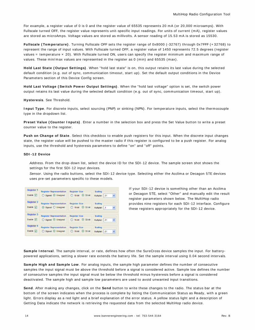
SDI-12 Device
Address. From the drop-down list, select the device ID for the SDI-12 device. The sample screen shot shows thesettings for the first SDI-12 input devices.Sensor. Using the radio buttons, select the SDI-12 device type. Selecting either the Acclima or Decagon 5TE devicesuses pre-set parameters specific to these models.
If your SDI-12 device is something other than an Acclimaor Decagon 5TE, select "Other" and manually edit the resultregister parameters shown below. The MultiHop radioprovides nine registers for each SDI-12 interface. Configurethese registers appropriately for the SDI-12 device.
Sample Interval. The sample interval, or rate, defines how often the SureCross device samples the input. For battery-powered applications, setting a slower rate extends the battery life. Set the sample interval using 0.04 second intervals.
Sample High and Sample Low. For analog inputs, the sample high parameter defines the number of consecutivesamples the input signal must be above the threshold before a signal is considered active. Sample low defines the numberof consecutive samples the input signal must be below the threshold minus hysteresis before a signal is considereddeactivated. The sample high and sample low parameters are used to avoid unwanted input transitions.
Send. After making any changes, click on the Send button to write these changes to the radio. The status bar at thebottom of the screen indicates when the process is complete by listing the Communication Status as Ready, with a greenlight. Errors display as a red light and a brief explanation of the error status. A yellow status light and a description ofGetting Data indicate the network is retrieving the requested data from the selected MultiHop radio device.
MultiHop Radio Configuration Tool
14 www.bannerengineering.com - tel: 763-544-3164 Rev. B
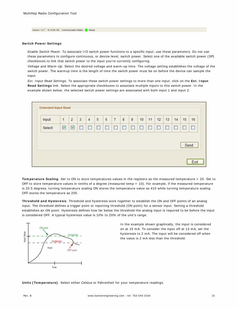
Switch Power Settings
Enable Switch Power. To associate I/O switch power functions to a specific input, use these parameters. Do not usethese parameters to configure continuous, or device-level, switch power. Select one of the available switch power (SP)checkboxes to link that switch power to the input you're currently configuring.Voltage and Warm-Up. Select the desired voltage and warm-up time. The voltage setting establishes the voltage of theswitch power. The warmup time is the length of time the switch power must be on before the device can sample theinput.Ext. Input Read Settings. To associate these switch power settings to more than one input, click on the Ext. InputRead Settings link. Select the appropriate checkboxes to associate multiple inputs to this switch power. In theexample shown below, the selected switch power settings are associated with both input 1 and input 2.
Temperature Scaling. Set to ON to store temperatures values in the registers as the measured temperature × 20. Set toOFF to store temperature values in tenths of a degree (measured temp × 10). For example, if the measured temperatureis 20.5 degrees, turning temperature scaling ON stores the temperature value as 410 while turning temperature scalingOFF stores the temperature as 205.
Threshold and Hysteresis. Threshold and hysteresis work together to establish the ON and OFF points of an analoginput. The threshold defines a trigger point or reporting threshold (ON point) for a sensor input. Setting a thresholdestablishes an ON point. Hysteresis defines how far below the threshold the analog input is required to be before the inputis considered OFF. A typical hysteresis value is 10% to 20% of the unit’s range.
Threshold
ON point
Time
Input
Value
Input
Hysteresis
OFF point
In the example shown graphically, the input is consideredon at 15 mA. To consider the input off at 13 mA, set thehysteresis to 2 mA. The input will be considered off whenthe value is 2 mA less than the threshold.
Units (Temperature). Select either Celsius or Fahrenheit for your temperature readings.
MultiHop Radio Configuration Tool
Rev. B www.bannerengineering.com - tel: 763-544-3164 15
Voltage. To set a voltage for the switch power output, select a value. When configured for continuous voltage output, thisswitch power output no longer cycles on, warms up the sensors, then cycles back down. Because the output voltageremains constant, continuous voltage is typically used with solar power installations.
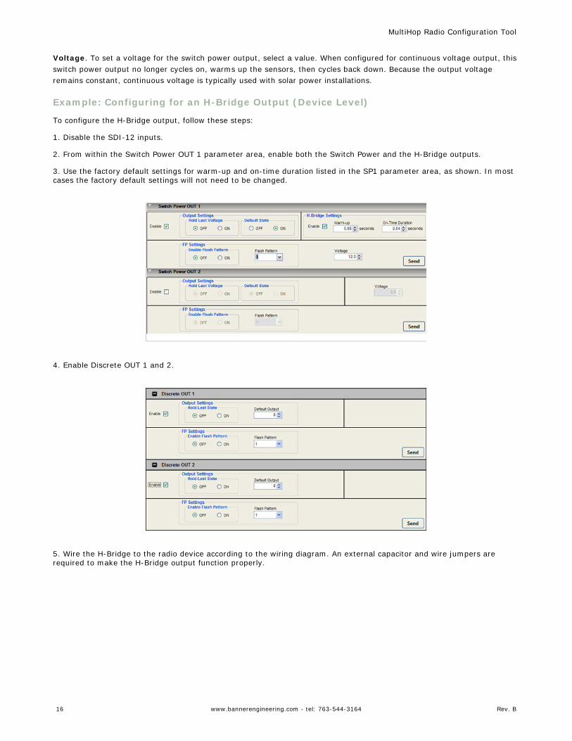
Example: Configuring for an H-Bridge Output (Device Level)
To configure the H-Bridge output, follow these steps:
1. Disable the SDI-12 inputs.
2. From within the Switch Power OUT 1 parameter area, enable both the Switch Power and the H-Bridge outputs.
3. Use the factory default settings for warm-up and on-time duration listed in the SP1 parameter area, as shown. In mostcases the factory default settings will not need to be changed.
4. Enable Discrete OUT 1 and 2.
5. Wire the H-Bridge to the radio device according to the wiring diagram. An external capacitor and wire jumpers arerequired to make the H-Bridge output function properly.
MultiHop Radio Configuration Tool
16 www.bannerengineering.com - tel: 763-544-3164 Rev. B
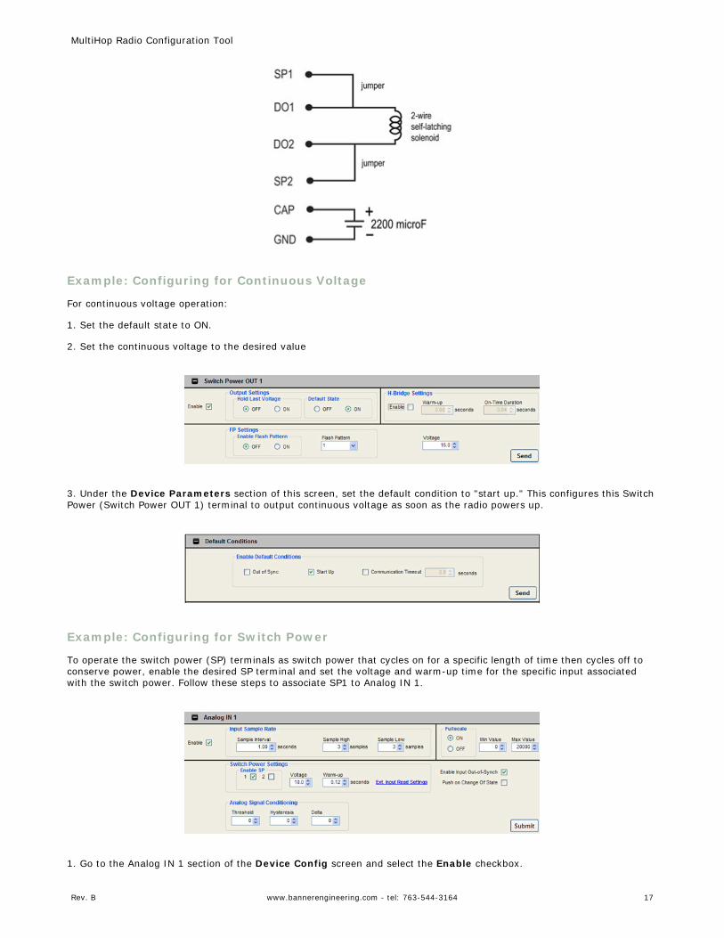
Example: Configuring for Continuous Voltage
For continuous voltage operation:
1. Set the default state to ON.
2. Set the continuous voltage to the desired value
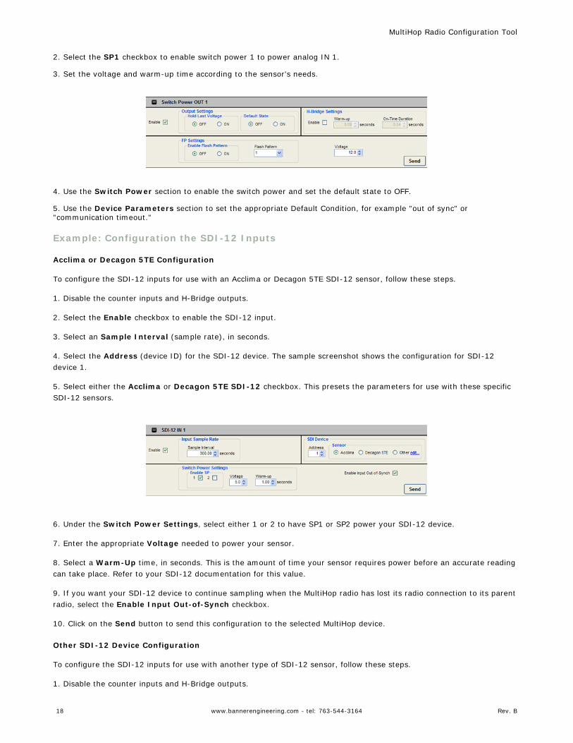
3. Under the Device Parameters section of this screen, set the default condition to "start up." This configures this SwitchPower (Switch Power OUT 1) terminal to output continuous voltage as soon as the radio powers up.
Example: Configuring for Switch Power
To operate the switch power (SP) terminals as switch power that cycles on for a specific length of time then cycles off toconserve power, enable the desired SP terminal and set the voltage and warm-up time for the specific input associatedwith the switch power. Follow these steps to associate SP1 to Analog IN 1.
1. Go to the Analog IN 1 section of the Device Config screen and select the Enable checkbox.
MultiHop Radio Configuration Tool
Rev. B www.bannerengineering.com - tel: 763-544-3164 17
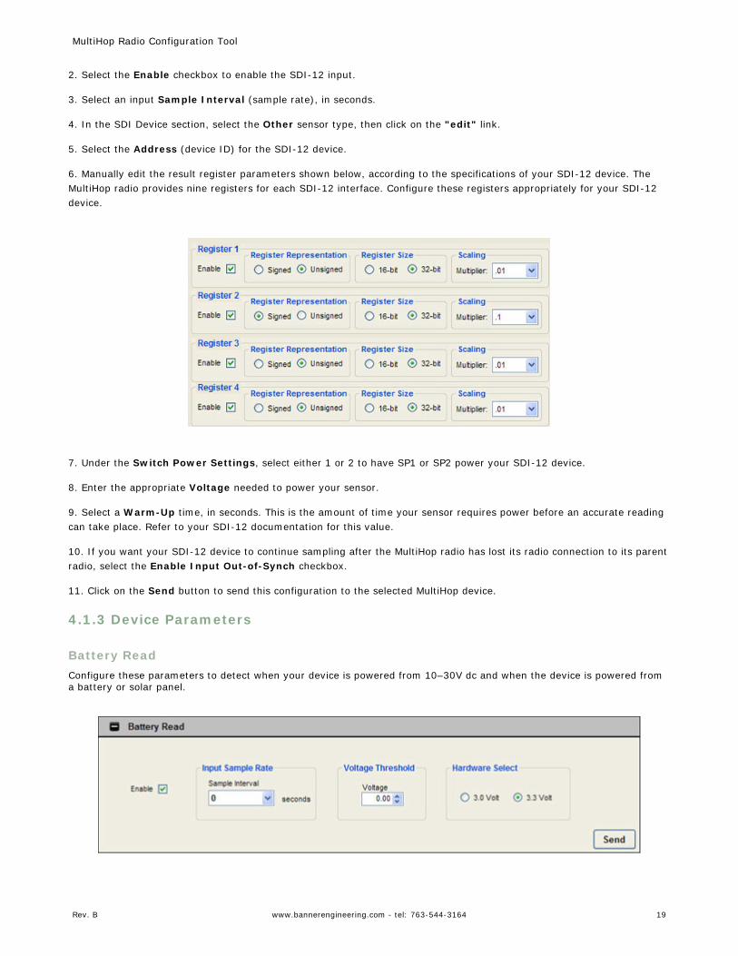
2. Select the SP1 checkbox to enable switch power 1 to power analog IN 1.
3. Set the voltage and warm-up time according to the sensor's needs.
4. Use the Switch Power section to enable the switch power and set the default state to OFF.
5. Use the Device Parameters section to set the appropriate Default Condition, for example "out of sync" or"communication timeout."
Example: Configuration the SDI-12 Inputs
Acclima or Decagon 5TE Configuration
To configure the SDI-12 inputs for use with an Acclima or Decagon 5TE SDI-12 sensor, follow these steps.
1. Disable the counter inputs and H-Bridge outputs.
2. Select the Enable checkbox to enable the SDI-12 input.
3. Select an Sample Interval (sample rate), in seconds.
4. Select the Address (device ID) for the SDI-12 device. The sample screenshot shows the configuration for SDI-12device 1.
5. Select either the Acclima or Decagon 5TE SDI-12 checkbox. This presets the parameters for use with these specificSDI-12 sensors.
6. Under the Switch Power Settings, select either 1 or 2 to have SP1 or SP2 power your SDI-12 device.
7. Enter the appropriate Voltage needed to power your sensor.
8. Select a Warm-Up time, in seconds. This is the amount of time your sensor requires power before an accurate readingcan take place. Refer to your SDI-12 documentation for this value.
9. If you want your SDI-12 device to continue sampling when the MultiHop radio has lost its radio connection to its parentradio, select the Enable Input Out-of-Synch checkbox.
10. Click on the Send button to send this configuration to the selected MultiHop device.
Other SDI-12 Device Configuration
To configure the SDI-12 inputs for use with another type of SDI-12 sensor, follow these steps.
1. Disable the counter inputs and H-Bridge outputs.
MultiHop Radio Configuration Tool
18 www.bannerengineering.com - tel: 763-544-3164 Rev. B
2. Select the Enable checkbox to enable the SDI-12 input.
3. Select an input Sample Interval (sample rate), in seconds.
4. In the SDI Device section, select the Other sensor type, then click on the "edit" link.
5. Select the Address (device ID) for the SDI-12 device.
6. Manually edit the result register parameters shown below, according to the specifications of your SDI-12 device. TheMultiHop radio provides nine registers for each SDI-12 interface. Configure these registers appropriately for your SDI-12device.
7. Under the Switch Power Settings, select either 1 or 2 to have SP1 or SP2 power your SDI-12 device.
8. Enter the appropriate Voltage needed to power your sensor.
9. Select a Warm-Up time, in seconds. This is the amount of time your sensor requires power before an accurate readingcan take place. Refer to your SDI-12 documentation for this value.
10. If you want your SDI-12 device to continue sampling after the MultiHop radio has lost its radio connection to its parentradio, select the Enable Input Out-of-Synch checkbox.
11. Click on the Send button to send this configuration to the selected MultiHop device.
4.1.3 Device Parameters
Battery ReadConfigure these parameters to detect when your device is powered from 10–30V dc and when the device is powered froma battery or solar panel.
MultiHop Radio Configuration Tool
Rev. B www.bannerengineering.com - tel: 763-544-3164 19
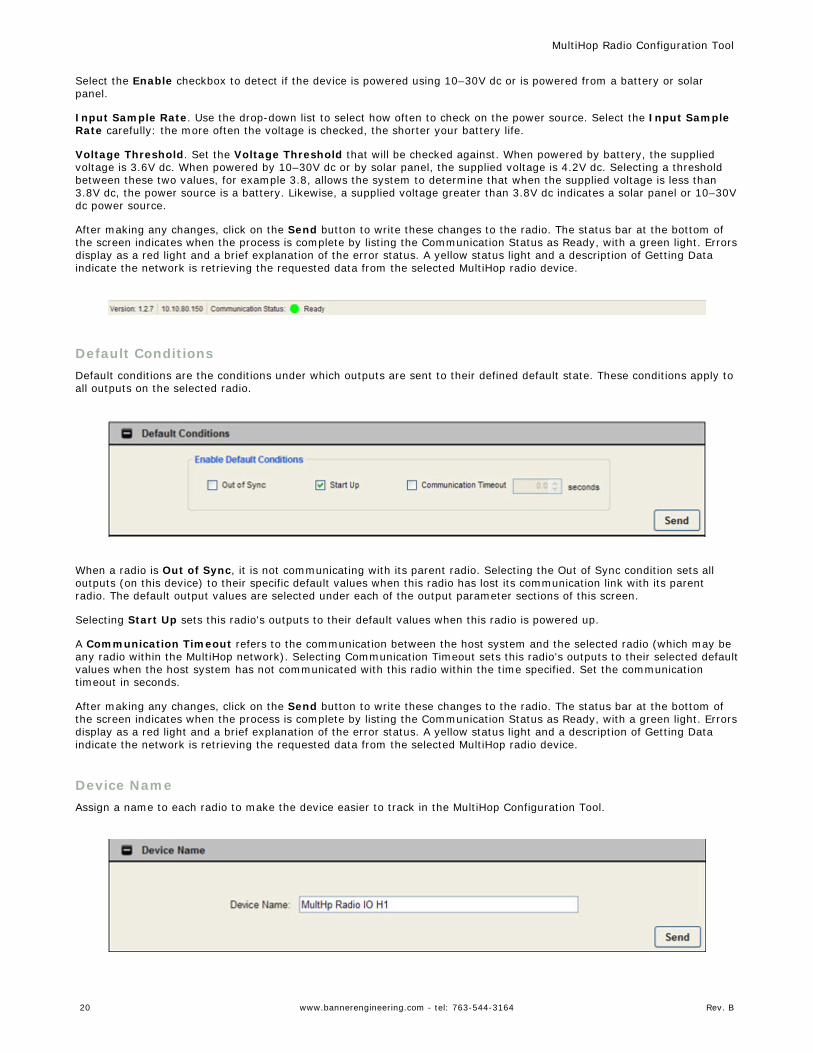
Select the Enable checkbox to detect if the device is powered using 10–30V dc or is powered from a battery or solarpanel.
Input Sample Rate. Use the drop-down list to select how often to check on the power source. Select the Input SampleRate carefully: the more often the voltage is checked, the shorter your battery life.
Voltage Threshold. Set the Voltage Threshold that will be checked against. When powered by battery, the suppliedvoltage is 3.6V dc. When powered by 10–30V dc or by solar panel, the supplied voltage is 4.2V dc. Selecting a thresholdbetween these two values, for example 3.8, allows the system to determine that when the supplied voltage is less than3.8V dc, the power source is a battery. Likewise, a supplied voltage greater than 3.8V dc indicates a solar panel or 10–30Vdc power source.
After making any changes, click on the Send button to write these changes to the radio. The status bar at the bottom ofthe screen indicates when the process is complete by listing the Communication Status as Ready, with a green light. Errorsdisplay as a red light and a brief explanation of the error status. A yellow status light and a description of Getting Dataindicate the network is retrieving the requested data from the selected MultiHop radio device.
Default ConditionsDefault conditions are the conditions under which outputs are sent to their defined default state. These conditions apply toall outputs on the selected radio.
When a radio is Out of Sync, it is not communicating with its parent radio. Selecting the Out of Sync condition sets alloutputs (on this device) to their specific default values when this radio has lost its communication link with its parentradio. The default output values are selected under each of the output parameter sections of this screen.
Selecting Start Up sets this radio's outputs to their default values when this radio is powered up.
A Communication Timeout refers to the communication between the host system and the selected radio (which may beany radio within the MultiHop network). Selecting Communication Timeout sets this radio's outputs to their selected defaultvalues when the host system has not communicated with this radio within the time specified. Set the communicationtimeout in seconds.
After making any changes, click on the Send button to write these changes to the radio. The status bar at the bottom ofthe screen indicates when the process is complete by listing the Communication Status as Ready, with a green light. Errorsdisplay as a red light and a brief explanation of the error status. A yellow status light and a description of Getting Dataindicate the network is retrieving the requested data from the selected MultiHop radio device.
Device NameAssign a name to each radio to make the device easier to track in the MultiHop Configuration Tool.
MultiHop Radio Configuration Tool
20 www.bannerengineering.com - tel: 763-544-3164 Rev. B
The Device Name, which appears on the Network View screen, must be less than 18 characters and contain onlystandard ASCII characters.
After making any changes, click on the Send button to write these changes to the radio. The status bar at the bottom ofthe screen indicates when the process is complete by listing the Communication Status as Ready, with a green light. Errorsdisplay as a red light and a brief explanation of the error status. A yellow status light and a description of Getting Dataindicate the network is retrieving the requested data from the selected MultiHop radio device.
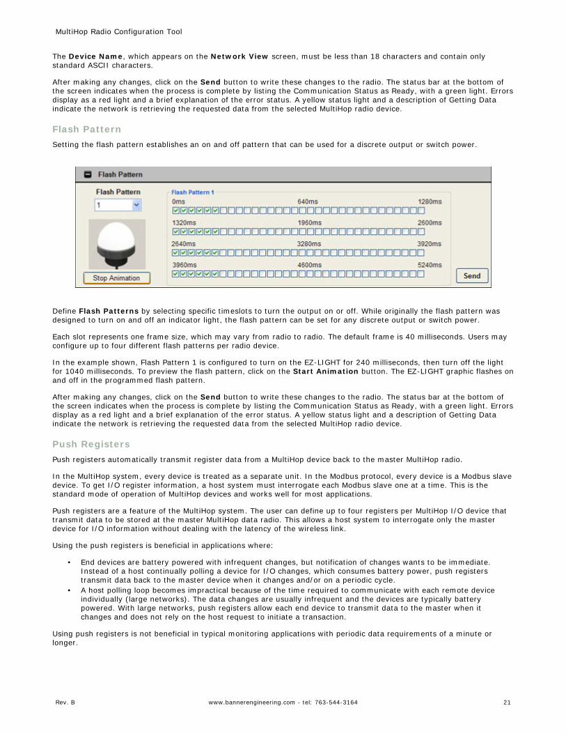
Flash PatternSetting the flash pattern establishes an on and off pattern that can be used for a discrete output or switch power.
Define Flash Patterns by selecting specific timeslots to turn the output on or off. While originally the flash pattern wasdesigned to turn on and off an indicator light, the flash pattern can be set for any discrete output or switch power.
Each slot represents one frame size, which may vary from radio to radio. The default frame is 40 milliseconds. Users mayconfigure up to four different flash patterns per radio device.
In the example shown, Flash Pattern 1 is configured to turn on the EZ-LIGHT for 240 milliseconds, then turn off the lightfor 1040 milliseconds. To preview the flash pattern, click on the Start Animation button. The EZ-LIGHT graphic flashes onand off in the programmed flash pattern.
After making any changes, click on the Send button to write these changes to the radio. The status bar at the bottom ofthe screen indicates when the process is complete by listing the Communication Status as Ready, with a green light. Errorsdisplay as a red light and a brief explanation of the error status. A yellow status light and a description of Getting Dataindicate the network is retrieving the requested data from the selected MultiHop radio device.
Push RegistersPush registers automatically transmit register data from a MultiHop device back to the master MultiHop radio.
In the MultiHop system, every device is treated as a separate unit. In the Modbus protocol, every device is a Modbus slavedevice. To get I/O register information, a host system must interrogate each Modbus slave one at a time. This is thestandard mode of operation of MultiHop devices and works well for most applications.
Push registers are a feature of the MultiHop system. The user can define up to four registers per MultiHop I/O device thattransmit data to be stored at the master MultiHop data radio. This allows a host system to interrogate only the masterdevice for I/O information without dealing with the latency of the wireless link.
Using the push registers is beneficial in applications where:
• End devices are battery powered with infrequent changes, but notification of changes wants to be immediate.Instead of a host continually polling a device for I/O changes, which consumes battery power, push registerstransmit data back to the master device when it changes and/or on a periodic cycle.
• A host polling loop becomes impractical because of the time required to communicate with each remote deviceindividually (large networks). The data changes are usually infrequent and the devices are typically batterypowered. With large networks, push registers allow each end device to transmit data to the master when itchanges and does not rely on the host request to initiate a transaction.
Using push registers is not beneficial in typical monitoring applications with periodic data requirements of a minute orlonger.
MultiHop Radio Configuration Tool
Rev. B www.bannerengineering.com - tel: 763-544-3164 21
A side benefit of using the push registers is the ability to use a device status register for each MultiHop device. With a pushregister interval defined, a master device sweep interval can be defined to verify the communication of each devicepushing data back to the master device. During the master sweep interval, every device must communicate with themaster device or the status register will be zero (missed communications).
For more information, refer to the Technical Note on MultiHop push registers.
Reading Push Registers
To read the push register data from the master device, send a Modbus read command to the remote slave ID forregisters 47909-47912 (push registers 1-4). The master device intercepts the Modbus command to the remote slave(because of the register addresses) and substitutes the local cached register values.
Read the status register for a MultiHop device the same as reading the push registers: the host sends a Modbus readcommand to the remote slave ID and register 47904. To use the status register for each MultiHop device, the mastersweep interval must be defined using the MultiHop Configuration tool.
A status register value of zero indicates no device; a value of one (1) indicates the device has reported.
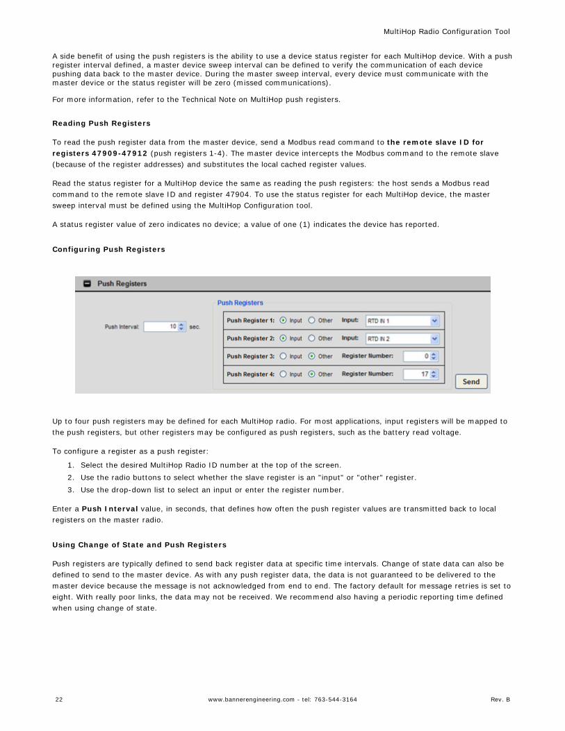
Configuring Push Registers
Up to four push registers may be defined for each MultiHop radio. For most applications, input registers will be mapped tothe push registers, but other registers may be configured as push registers, such as the battery read voltage.
To configure a register as a push register:
1. Select the desired MultiHop Radio ID number at the top of the screen.2. Use the radio buttons to select whether the slave register is an "input" or "other" register.3. Use the drop-down list to select an input or enter the register number.
Enter a Push Interval value, in seconds, that defines how often the push register values are transmitted back to localregisters on the master radio.
Using Change of State and Push Registers
Push registers are typically defined to send back register data at specific time intervals. Change of state data can also bedefined to send to the master device. As with any push register data, the data is not guaranteed to be delivered to themaster device because the message is not acknowledged from end to end. The factory default for message retries is set toeight. With really poor links, the data may not be received. We recommend also having a periodic reporting time definedwhen using change of state.
MultiHop Radio Configuration Tool
22 www.bannerengineering.com - tel: 763-544-3164 Rev. B
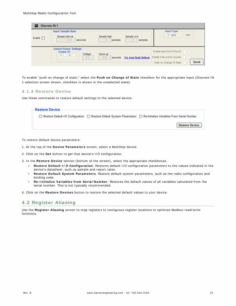
To enable "push on change of state," select the Push on Change of State checkbox for the appropriate input (Discrete IN1 selection screen shown, checkbox is shown in the unselected state).
4.1.4 Restore DeviceUse these commands to restore default settings to the selected device.
To restore default device parameters:
1. At the top of the Device Parameters screen, select a MultiHop device.
2. Click on the Get button to get that device's I/O configuration.
3. In the Restore Device section (bottom of the screen), select the appropriate checkboxes.• Restore Default I/O Configuration. Restores default I/O configuration parameters to the values indicated in the
device's datasheet, such as sample and report rates.• Restore Default System Parameters. Restore default system parameters, such as the radio configuration and
binding code.• Re-Initialize Variables from Serial Number. Restores the default values of all variables calculated from the
serial number. This is not typically recommended.
4. Click on the Restore Devices button to restore the selected default values to your device.
4.2 Register AliasingUse the Register Aliasing screen to map registers to contiguous register locations to optimize Modbus read/writefunctions.
MultiHop Radio Configuration Tool
Rev. B www.bannerengineering.com - tel: 763-544-3164 23
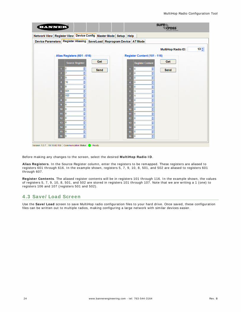
Before making any changes to the screen, select the desired MultiHop Radio ID.
Alias Registers. In the Source Register column, enter the registers to be remapped. These registers are aliased toregisters 601 through 616. In the example shown, registers 5, 7, 9, 10, 8, 501, and 502 are aliased to registers 601through 607.
Register Contents. The aliased register contents will be in registers 101 through 116. In the example shown, the valuesof registers 5, 7, 9, 10, 8, 501, and 502 are stored in registers 101 through 107. Note that we are writing a 1 (one) toregisters 106 and 107 (registers 501 and 502).
4.3 Save/Load ScreenUse the Save/Load screen to save MultiHop radio configuration files to your hard drive. Once saved, these configurationfiles can be written out to multiple radios, making configuring a large network with similar devices easier.
MultiHop Radio Configuration Tool
24 www.bannerengineering.com - tel: 763-544-3164 Rev. B
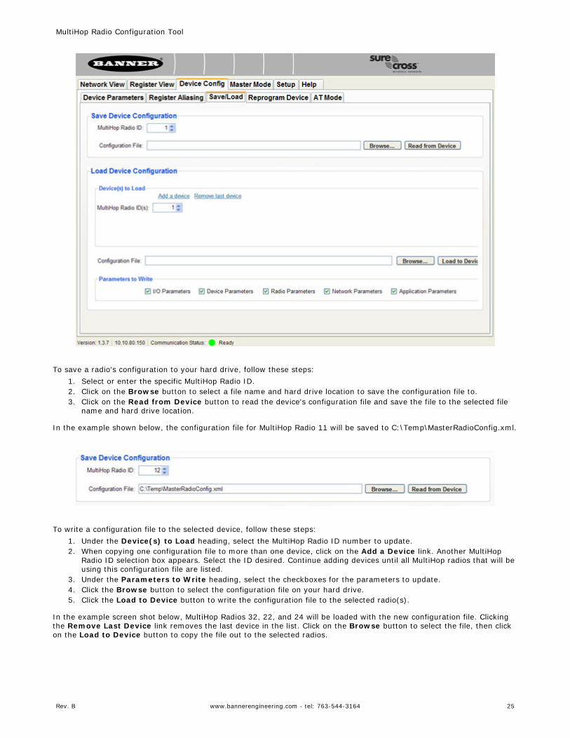
To save a radio's configuration to your hard drive, follow these steps:1. Select or enter the specific MultiHop Radio ID.2. Click on the Browse button to select a file name and hard drive location to save the configuration file to.3. Click on the Read from Device button to read the device's configuration file and save the file to the selected file
name and hard drive location.
In the example shown below, the configuration file for MultiHop Radio 11 will be saved to C:\Temp\MasterRadioConfig.xml.
To write a configuration file to the selected device, follow these steps:1. Under the Device(s) to Load heading, select the MultiHop Radio ID number to update.2. When copying one configuration file to more than one device, click on the Add a Device link. Another MultiHop
Radio ID selection box appears. Select the ID desired. Continue adding devices until all MultiHop radios that will beusing this configuration file are listed.
3. Under the Parameters to Write heading, select the checkboxes for the parameters to update.4. Click the Browse button to select the configuration file on your hard drive.5. Click the Load to Device button to write the configuration file to the selected radio(s).
In the example screen shot below, MultiHop Radios 32, 22, and 24 will be loaded with the new configuration file. Clickingthe Remove Last Device link removes the last device in the list. Click on the Browse button to select the file, then clickon the Load to Device button to copy the file out to the selected radios.
MultiHop Radio Configuration Tool
Rev. B www.bannerengineering.com - tel: 763-544-3164 25
Parameters to Write. By default, all parameters are selected when writing a configuration file to a device. At this time,only the I/O Parameters and Device Parameters are actually used. Both the I/O and Device Parameters are listed onthe Device Config screen.
The I/O Parameters section allows the user to select which I/O points are enabled, the I/O point's sample rate, and otherparameters specific to the I/O. The Device Parameters include the default condition, flash pattern, and device name.
Radio Parameters, Network Parameters, and Application Parameters are not used at this time and are reserved forfuture use.
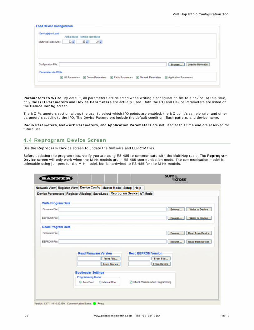
4.4 Reprogram Device ScreenUse the Reprogram Device screen to update the firmware and EEPROM files.
Before updating the program files, verify you are using RS-485 to communicate with the MultiHop radio. The ReprogramDevice screen will only work when the M-Hx models are in RS-485 communication mode. The communication model isselectable using jumpers for the M-H model, but is hardwired to RS-485 for the M-Hx models.
MultiHop Radio Configuration Tool
26 www.bannerengineering.com - tel: 763-544-3164 Rev. B
4.4 Updating Program Files Using Auto Book Mode
To write a new version of the firmware or EEPROM files to the device:
1. Under the Read Firmware Version heading, click the From Device button to read the Firmware part number andversion number from the device.
2. Under the Read EEPROM Version heading, click the From Device button to read the EEPROM part number andversion number from the device.
3. Under the Write Program Data heading, click on the Browse button.4. Select the new file from your harddrive, verifying you have selected a Firmware and/or EEPROM part number that
matches the part number currently on your device.5. Click on the Write to Device button to write this new file out to the radio.6. A dialogue box pops up to verify you want to overwrite the configuration file already on the data radio. Click on OK
to continue or Cancel to cancel the write process.7. The Communication Status display at the bottom of the screen indicates when the configuration tool has finished
writing the file out to the radio. When the status is "Ready," the process is complete. If there are errors during theprogramming process, use manual mode to update the files.
4.4 Updating Program Files Using Manual Boot Mode1. At the bottom of the page, select the Manual Boot button and unselect the Check Version when Programming
checkbox.2. Read the firmware version of your radio by clicking on the From Device button under the Read Firmware
Version section.3. Cycle power to the radio by disconnecting then reconnecting the power to the radio. The firmware version will be
read when the radio reboots.4. After the radio reboots, use the Write Program Data section of the screen to browse to the firmware file location
on your harddrive. Select the appropriate files.5. Click the Write to Device button for the firmware, then click OK on the pop-up box to start the process.6. Immediately cycle power to the MultiHop radio.7. Complete the same steps for the EEPROM if necessary.
4.4 Saving Program Data to Your Hard Drive
To save your firmware or EEPROM files to your harddrive:
1. Click on the Browse button to select a location and file name on your computer.2. Click on the Read from Device button to read the file from the radio.
4.4 Comparing Version Numbers
Display the firmware or EEPROM versions of the device or a specific file on your harddrive by clicking on the appropriatebutton under the Read Firmware Version or Read EEPROM Version headings.
Clicking the From File button allows you to choose a file on your harddrive. Clicking the From Device button loads theversion from the radio selected by the MultiHop Radio ID.
4.4 Reprogram Device Settings
After reading from or writing to a radio, you must boot the radio.
Select Auto Boot to set the radio to automatically cycle power after changes are made to the firmware or EEPROM files.This is the recommended setting.
Select Manual Boot to manually cycle power to the radio after changes are made or the files are read. You must manuallycycle power to the radio within 15 seconds of writing to or reading from the radio.
MultiHop Radio Configuration Tool
Rev. B www.bannerengineering.com - tel: 763-544-3164 27
Select the Check Version When Programming checkbox to have the Configuration Tool automatically verify thefirmware or EEPROM file features match the features of your radio. For example, selecting this option allows theConfiguration Tool to verify you aren't trying to write the firmware or EEPROM for an I/O radio to a data radio that doesnot have I/O.
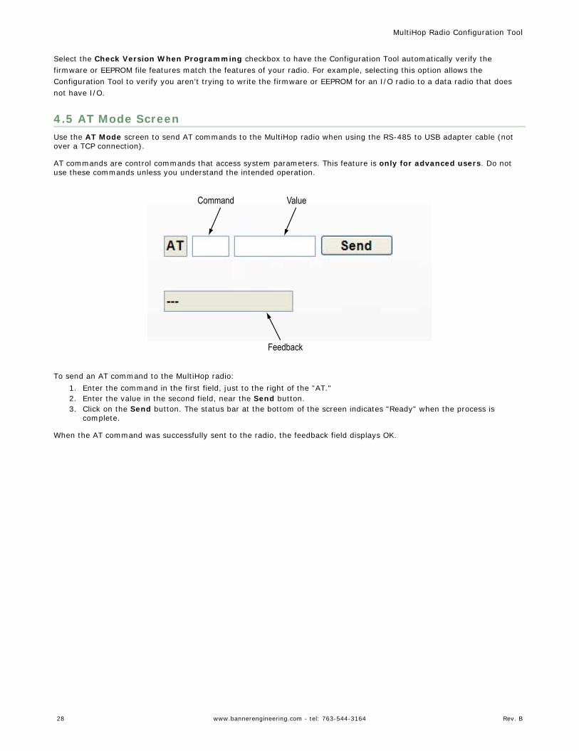
4.5 AT Mode ScreenUse the AT Mode screen to send AT commands to the MultiHop radio when using the RS-485 to USB adapter cable (notover a TCP connection).
AT commands are control commands that access system parameters. This feature is only for advanced users. Do notuse these commands unless you understand the intended operation.
Command Value
Feedback
To send an AT command to the MultiHop radio:1. Enter the command in the first field, just to the right of the "AT."2. Enter the value in the second field, near the Send button.3. Click on the Send button. The status bar at the bottom of the screen indicates "Ready" when the process is
complete.
When the AT command was successfully sent to the radio, the feedback field displays OK.
MultiHop Radio Configuration Tool
28 www.bannerengineering.com - tel: 763-544-3164 Rev. B
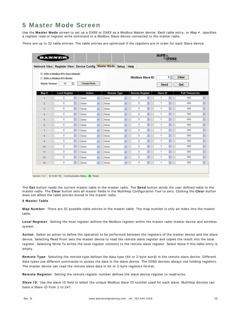
5 Master Mode ScreenUse the Master Mode screen to set up a DX85 or DX83 as a Modbus Master device. Each table entry, or Map #, specifiesa register read or register write command to a Modbus Slave device connected to the master radio.
There are up to 32 table entries. The table entries are optimized if the registers are in order for each Slave device.
The Get button reads the current master table in the master radio. The Send button sends the user defined table to themaster radio. The Clear button sets all master fields in the MultiHop Configuration Tool to zero. Clicking the Clear buttondoes not affect the table entries stored in the master radio.
5 Master Table
Map Number: There are 32 possible table entries in the master table. The map number is only an index into the mastertable.
Local Register: Setting the local register defines the Modbus register within the master radio master device and wirelesssystem.
Action: Select an action to define the operation to be performed between the registers of the master device and the slavedevice. Selecting Read From sets the master device to read the remote slave register and copies the result into the localregister. Selecting Write To writes the local register contents to the remote slave register. Select None if this table entry isempty.
Remote Type: Selecting the remote type defines the data type (bit or 2-byte word) in the remote slave device. Differentdata types use different commands to access the data in the slave device. The DX80 devices always use holding registers.The master device can read the remote slave data in bit or 2-byte registers format.
Remote Register: Setting the remote register number defines the slave device register to read/write.
Slave ID: Use the slave ID field to select the unique Modbus slave ID number used for each slave. MultiHop devices canhave a Slave ID from 1 to 247.
Rev. B www.bannerengineering.com - tel: 763-544-3164 29
Poll Timeout (ms): The poll timeout value defines how long the master waits for a slave response when performing thatmap action. If the slave device’s response is not received within the timeout period, the master device continues to thenext table entry.
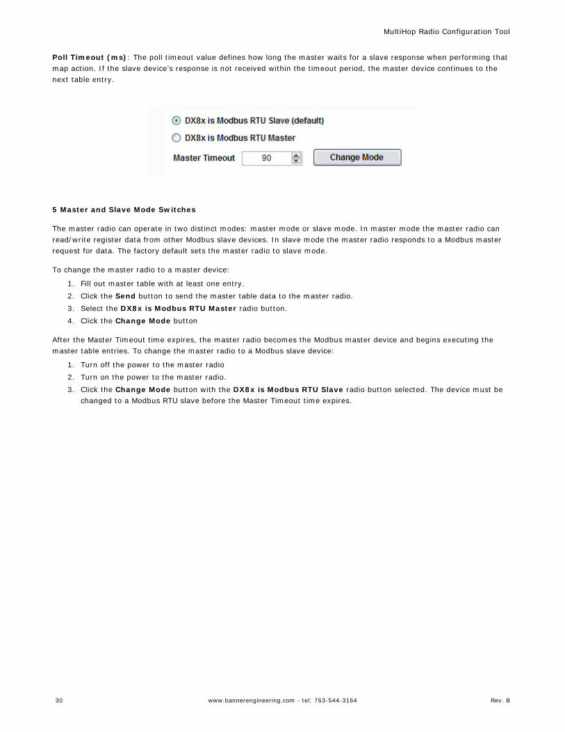
5 Master and Slave Mode Switches
The master radio can operate in two distinct modes: master mode or slave mode. In master mode the master radio canread/write register data from other Modbus slave devices. In slave mode the master radio responds to a Modbus masterrequest for data. The factory default sets the master radio to slave mode.
To change the master radio to a master device:
1. Fill out master table with at least one entry.2. Click the Send button to send the master table data to the master radio.3. Select the DX8x is Modbus RTU Master radio button.4. Click the Change Mode button
After the Master Timeout time expires, the master radio becomes the Modbus master device and begins executing themaster table entries. To change the master radio to a Modbus slave device:
1. Turn off the power to the master radio2. Turn on the power to the master radio.3. Click the Change Mode button with the DX8x is Modbus RTU Slave radio button selected. The device must be
changed to a Modbus RTU slave before the Master Timeout time expires.
MultiHop Radio Configuration Tool
30 www.bannerengineering.com - tel: 763-544-3164 Rev. B
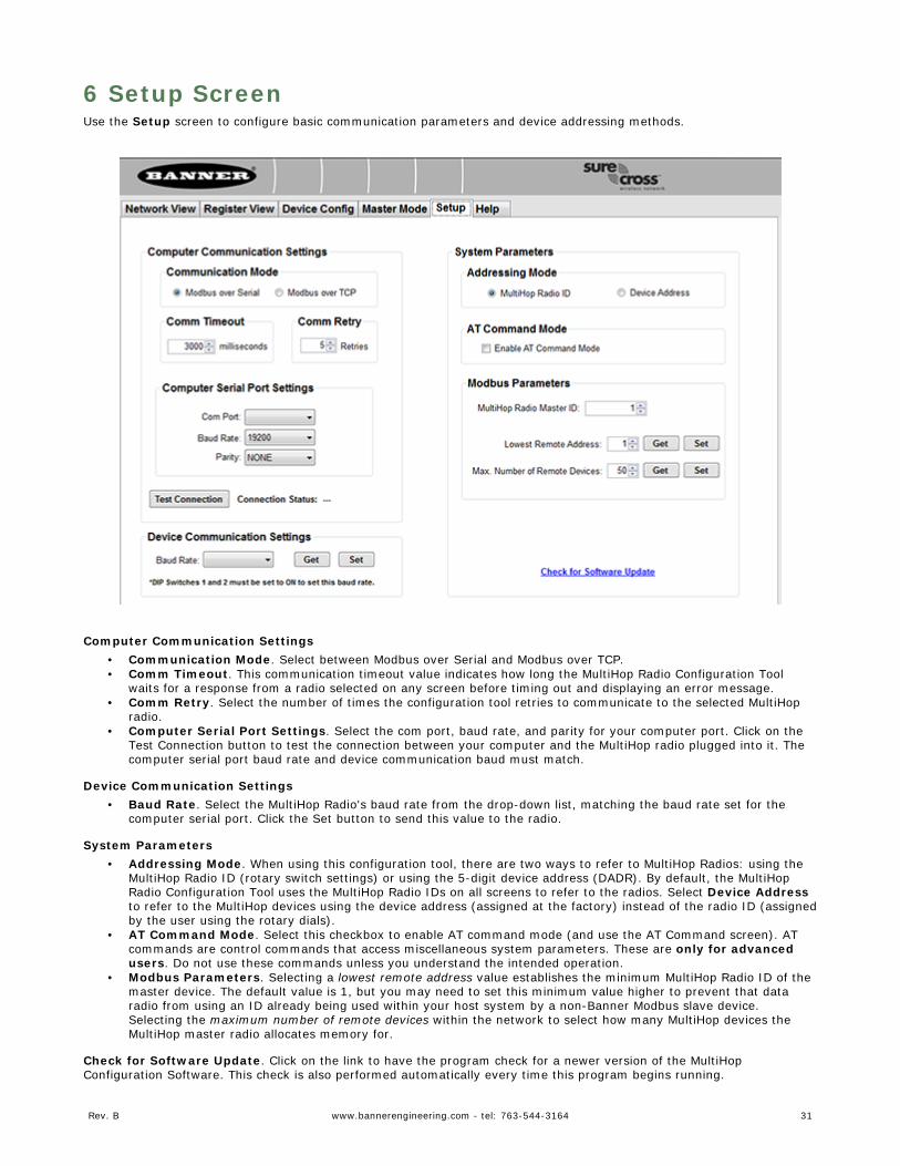
6 Setup ScreenUse the Setup screen to configure basic communication parameters and device addressing methods.
Computer Communication Settings• Communication Mode. Select between Modbus over Serial and Modbus over TCP.• Comm Timeout. This communication timeout value indicates how long the MultiHop Radio Configuration Tool
waits for a response from a radio selected on any screen before timing out and displaying an error message.• Comm Retry. Select the number of times the configuration tool retries to communicate to the selected MultiHop
radio.• Computer Serial Port Settings. Select the com port, baud rate, and parity for your computer port. Click on the
Test Connection button to test the connection between your computer and the MultiHop radio plugged into it. Thecomputer serial port baud rate and device communication baud must match.
Device Communication Settings• Baud Rate. Select the MultiHop Radio's baud rate from the drop-down list, matching the baud rate set for the
computer serial port. Click the Set button to send this value to the radio.
System Parameters• Addressing Mode. When using this configuration tool, there are two ways to refer to MultiHop Radios: using the
MultiHop Radio ID (rotary switch settings) or using the 5-digit device address (DADR). By default, the MultiHopRadio Configuration Tool uses the MultiHop Radio IDs on all screens to refer to the radios. Select Device Addressto refer to the MultiHop devices using the device address (assigned at the factory) instead of the radio ID (assignedby the user using the rotary dials).
• AT Command Mode. Select this checkbox to enable AT command mode (and use the AT Command screen). ATcommands are control commands that access miscellaneous system parameters. These are only for advancedusers. Do not use these commands unless you understand the intended operation.
• Modbus Parameters. Selecting a lowest remote address value establishes the minimum MultiHop Radio ID of themaster device. The default value is 1, but you may need to set this minimum value higher to prevent that dataradio from using an ID already being used within your host system by a non-Banner Modbus slave device.Selecting the maximum number of remote devices within the network to select how many MultiHop devices theMultiHop master radio allocates memory for.
Check for Software Update. Click on the link to have the program check for a newer version of the MultiHopConfiguration Software. This check is also performed automatically every time this program begins running.
Rev. B www.bannerengineering.com - tel: 763-544-3164 31

After making any changes, click on the Send button to write these changes to the radio. The status bar at the bottom ofthe screen indicates when the process is complete by listing the Communication Status as Ready, with a green light. Errorsdisplay as a red light and a brief explanation of the error status. A yellow status light and a description of Getting Dataindicate the network is retrieving the requested data from the selected MultiHop radio device.
Click on the Get button to read parameters from the radio.
TCP Settings. MultiHop models can be assigned an IP address to allow users to access the radio over the Internet fromany computer instead of requiring the master radio be connected to the computer running the configuration tool. Assignthe device's IP address on this Setup screen. To access a MultiHop network using the IP address, enter the assignedaddress in the Communication Mode screen.
MultiHop Radio Configuration Tool
32 www.bannerengineering.com - tel: 763-544-3164 Rev. B
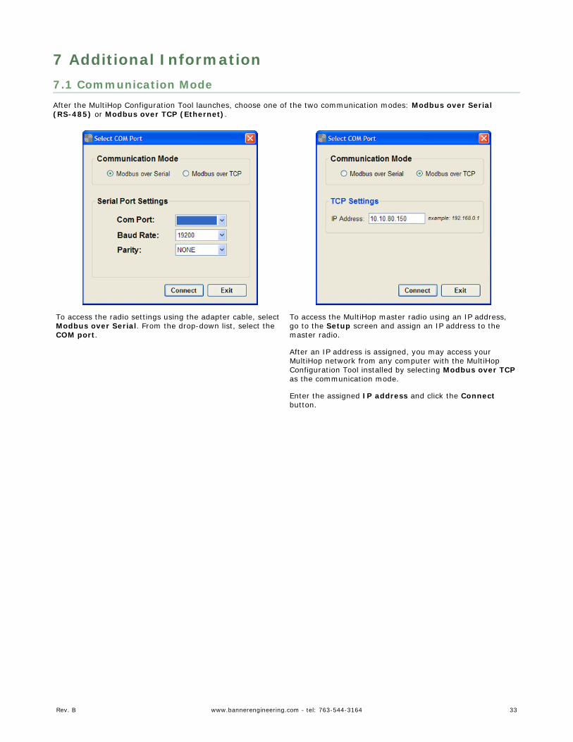
7 Additional Information7.1 Communication ModeAfter the MultiHop Configuration Tool launches, choose one of the two communication modes: Modbus over Serial(RS-485) or Modbus over TCP (Ethernet).
To access the radio settings using the adapter cable, selectModbus over Serial. From the drop-down list, select theCOM port.
To access the MultiHop master radio using an IP address,go to the Setup screen and assign an IP address to themaster radio.
After an IP address is assigned, you may access yourMultiHop network from any computer with the MultiHopConfiguration Tool installed by selecting Modbus over TCPas the communication mode.
Enter the assigned IP address and click the Connectbutton.
Rev. B www.bannerengineering.com - tel: 763-544-3164 33
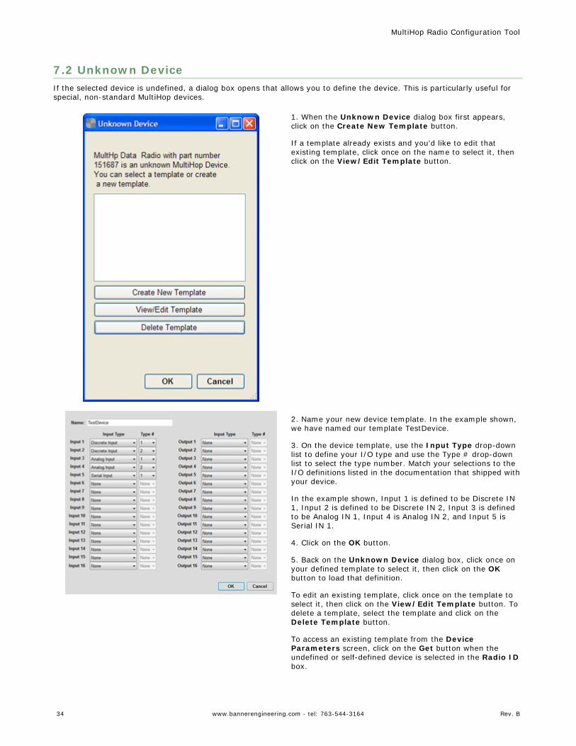
7.2 Unknown DeviceIf the selected device is undefined, a dialog box opens that allows you to define the device. This is particularly useful forspecial, non-standard MultiHop devices.
1. When the Unknown Device dialog box first appears,click on the Create New Template button.
If a template already exists and you'd like to edit thatexisting template, click once on the name to select it, thenclick on the View/Edit Template button.
2. Name your new device template. In the example shown,we have named our template TestDevice.
3. On the device template, use the Input Type drop-downlist to define your I/O type and use the Type # drop-downlist to select the type number. Match your selections to theI/O definitions listed in the documentation that shipped withyour device.
In the example shown, Input 1 is defined to be Discrete IN1, Input 2 is defined to be Discrete IN 2, Input 3 is definedto be Analog IN 1, Input 4 is Analog IN 2, and Input 5 isSerial IN 1.
4. Click on the OK button.
5. Back on the Unknown Device dialog box, click once onyour defined template to select it, then click on the OKbutton to load that definition.
To edit an existing template, click once on the template toselect it, then click on the View/Edit Template button. Todelete a template, select the template and click on theDelete Template button.
To access an existing template from the DeviceParameters screen, click on the Get button when theundefined or self-defined device is selected in the Radio IDbox.
MultiHop Radio Configuration Tool
34 www.bannerengineering.com - tel: 763-544-3164 Rev. B
IndexAaddressing mode 31AT command mode 31auto boot 26, 27
Ccable
USB to RS485 converter 3
Ddefault conditions 20device name 20
EEEPROM updates 26, 27
Ffirmware updates 26, 27flash pattern 21flash pattern frame size 21
Gget button 8
Iinstalling software 3
Lload configuration file 24local register 29, 30
Mmanual boot 26, 27
Modbusmaster 29, 30slave 29, 30
Modbus offset 31
Oout of sync 20
Ppoll timeout 29, 30
Rregister aliasing 23Register View Screen 7remote register 29, 30remote type 29, 30
Ssetup screen 31slave id 29, 30start up 20
Ttimeout
communication 20, 31
Uupdates
EEPROM 26, 27firmware 26, 27
Related Documents