Multifunctional Gate Box MGB EN

Welcome message from author
This document is posted to help you gain knowledge. Please leave a comment to let me know what you think about it! Share it to your friends and learn new things together.
Transcript
Multifunctional Gate BoxMGB
EN

2
Internationally successful – the EUCHNER company
EUCHNER GmbH + Co. KG is a world-leading company in the area of industrial safety technology. EUCHNER has been developing and producing high-quality switching sys-tems for mechanical and systems engineering for more than 60 years.The medium-sized family-operated company based in Leinfelden, Germany, employs more than 600 people around the world.
16 subsidiaries and other sales partners in Germany and abroad work for our inter-national success on the market.
Quality and innovation – the EUCHNER products
A look into the past shows EUCHNER to be a company with a great inventive spirit.We take the technological and ecological challenges of the future as an incentive for extraordinary product developments.
EUCHNER safety switches monitor safety doors on machines and installations, help to minimize dangers and risks and thereby reliably protect people and processes. Today, our products range from electromechanical and electronic components to intelligent integrated safety solutions. Safety for people, machines and products is one of our dominant themes.
We defi ne future safety technology with the highest quality standards and reliable technology. Extraordinary solutions ensure the great satisfaction of our customers. The product ranges are subdivided as follows:
Transponder-coded Safety Switches Transponder-coded Safety Switches with guard locking Multifunctional Gate Box MGB Access management systems (Electronic-Key-System EKS) Electromechanical Safety Switches Magnetically coded Safety Switches Enabling Switches Safety Relays Emergency Stop Devices Hand-Held Pendant Stations and Handwheels Safety Switches with AS-Interface Joystick Switches Position Switches
Headquarters in Leinfelden-Echterdingen
madeinGermany
Logistics center in Leinfelden-Echterdingen
Production location in Unterböhringen
Contents
3106109-09-03/16
General information 4
System overview and selection aid 7
Approvals and explanation of symbols 8
Multifunctional Gate Box MGB
System family MGB 9
Interlocking sets MGB-L0-... 10
Locking sets MGB-L1-... 16
Locking sets MGB-L2-... 38
Technical data and dimension drawings 50
System family MGB with control module 53
Interlocking sets MGB-L0C-AR... 54
Locking sets MGB-L1C-AR... 56
Locking sets MGB-L2C-AR... 58
Technical data and dimension drawings 60
Expansions and accessories for MGB-AP and MGB-AR 63
MG
B-A
RM
GB
-AP
MG
B-P
N
System family MGB-PN 85
Locking sets MGB-L1-PN... 86
Locking sets MGB-L2-PN... 98
Control modules MGB-...-PN... 114
Technical data and dimension drawing 120
Item index 124
Item index by item designation 124
Item index by order numbers 126
4
General
Subject to technical modifications; no responsibility is accepted for the accuracy of this information.
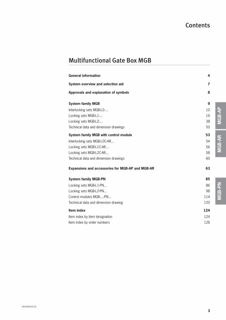
A handle on the future
The MGB (Multifunctional Gate Box) is a unique interlocking or guard locking system for the protection of safety doors on machines and systems.
The MGB offers that little bit more: it is more than a safety switch, more than a bolt, and offers a lot more functionality!
A system that can grow with your needsEven the basic system comprising handle module and evaluation module (as interlocking module or locking module) includes numerous functions.Whether interlocking, guard locking, escape release or other functions such as push buttons for start/stop, emergency stop, etc. – the MGB meets all your requirements for safety-related applications.
And if your needs grow, the MGB system grows with them. Due to the sophisticated modular design, the evaluation module can quickly become a small control panel.
Or with an additional control module straight awayIn the wide variety of different MGBs, you will definitely find the right one for your application. If not, using the control module you can add lamps, pushbuttons or even completely different operating functions. The con-trol module is permanently fastened to the evaluation module using the connection set.
Be certain of compliance with standardsPerformance Level e in accordance with EN ISO 13849-1 or SIL3 in accordance with EN 62061 – even with the basic system you meet all these requirements. Also the requirements of EN 14119 for protection against tampering are met automatically, as each evaluation module is permanently assigned to a handle module in the unicode version.
Everything at a glanceThe LED indicator continuously provides you with all important system information. Diagnostics and status check!
Solid end stopA mechanical stop for the handle module mounted in the door is perfectly integrated into the locking module MGB-L…. A marking on the stop makes adjustment easier.
Interlocking/ locking module
Space for ideas...Control elements and indicators in one housing cover turn the MGB into an all-rounder. Equipped with a start button, an emergency stop and/or other functions, the interlocking/locking module becomes a true control terminal.
Auxiliary releaseFor releasing the guard locking, e.g. in case of a power failure.
Flexible color cover adaptationThe colors of the pushbuttons can be adapted as required and interchanged. 5 different color covers are available for this purpose.
5
General
Subject to technical modifications; no responsibility is accepted for the accuracy of this information.
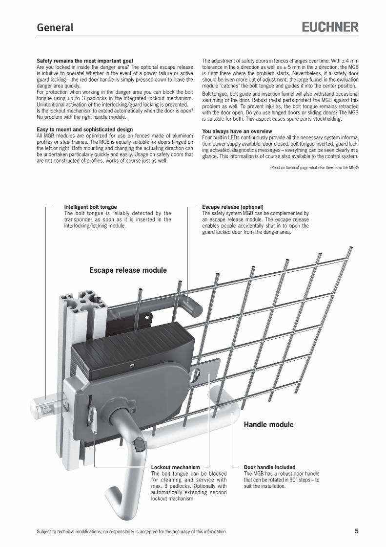
Safety remains the most important goalAre you locked in inside the danger area? The optional escape release is intuitive to operate! Whether in the event of a power failure or active guard locking – the red door handle is simply pressed down to leave the danger area quickly.For protection when working in the danger area you can block the bolt tongue using up to 3 padlocks in the integrated lockout mechanism. Unintentional activation of the interlocking/guard locking is prevented.Is the lockout mechanism to extend automatically when the door is open? No problem with the right handle module.
Easy to mount and sophisticated designAll MGB modules are optimized for use on fences made of aluminum profiles or steel frames. The MGB is equally suitable for doors hinged on the left or right. Both mounting and changing the actuating direction can be undertaken particularly quickly and easily. Usage on safety doors that are not constructed of profiles, works of course just as well.
The adjustment of safety doors in fences changes over time. With ± 4 mm tolerance in the x direction as well as ± 5 mm in the z direction, the MGB is right there where the problem starts. Nevertheless, if a safety door should be even more out of adjustment, the large funnel in the evaluation module "catches" the bolt tongue and guides it into the center position. Bolt tongue, bolt guide and insertion funnel will also withstand occasional slamming of the door. Robust metal parts protect the MGB against this problem as well. To prevent injuries, the bolt tongue remains retracted with the door open. Do you use hinged doors or sliding doors? The MGB is suitable for both. This aspect eases spare parts stockholding.
You always have an overviewFour built-in LEDs continuously provide all the necessary system informa-tion: power supply available, door closed, bolt tongue inserted, guard lock-ing activated, diagnostics messages – everything can be seen clearly at a glance. This information is of course also available to the control system.
(Read on the next page what else there is in the MGB!)
Lockout mechanismThe bolt tongue can be blocked for cleaning and service with max. 3 padlocks. Optionally with automatically extending second lockout mechanism.
Escape release (optional)The safety system MGB can be complemented by an escape release module. The escape release enables people accidentally shut in to open the guard locked door from the danger area.
Door handle includedThe MGB has a robust door handle that can be rotated in 90° steps – to suit the installation.
Intelligent bolt tongueThe bolt tongue is reliably detected by the transponder as soon as it is inserted in the interlocking/locking module.
Escape release module
Handle module

6
General
Subject to technical modifications; no responsibility is accepted for the accuracy of this information.
Sophisticated accessoriesWhether you need mounting plates for easier attachment, pre-assembled cables or a long escape release actuator axis (as the safety door needs to be very thick), you will find all you need in the accessories section.
Economical wiring according to standardsAll devices in the family AR can be wired directly in series in a so-called AR series connection without reducing safety or the PL. As a consequence evaluation units are saved. AR devices are also available in the EUCHNER series CES and CET.The family MGB-AP is particularly suitable for the protection of individual safety doors. If series connection is not necessary, wiring can then be saved. This version has different timing to the AR version.
Seamless integration by means of bus connectionIn the PROFINET version we now also make the wiring easier for you. You define which element is to be integrated and the related function. The MGB supplies the protocol frame with the necessary PROFINET input and output bytes required.Comprehensive diagnostic information in the form of PROFINET messages makes troubleshooting quick and specific. Due the typical ease with which parameters can be set in PROFINET, even the replacement of the system in case of service is a simple matter and can be undertaken in a few minutes.
Interlocking or guard locking?Functions of the versions MGB-L0, MGB-L1 and MGB-L2 compared
Interlocking devices (MGB-L0, without guard locking)Together with a handle module, the interlocking module makes it possible to interlock the control of movable safety guards. The combination also serves as a mechanical door stop at the same time.The following switch-on condition applies to the safety outputs FO1A and FO1B (see also System status table):
Safety guard closed (but can be opened at any time) Bolt tongue inserted in the interlocking module
The interlocking module detects the position of the safety guard and the position of the bolt tongue. The bolt tongue in the handle module is moved into and out of the inter-locking module by actuating the door handle.
Guard locking devices (MGB-L1 and MGB-L2)Together with a handle module, the locking module makes it possible to lock movable safety guards. The combination also serves as a mechanical door stop at the same time.The following switch-on condition applies to the safety outputs FO1A and FO1B (see also System status table):
Safety guard closed Bolt tongue inserted in the locking module Locking arm in locking position (the door cannot be opened)
The locking module detects the position of the safety guard and the position of the bolt tongue. The position of the guard locking is also monitored.The bolt tongue in the handle module is moved into and out of the locking module by actuating the door handle.When the bolt tongue is fully inserted in the locking module, the locking arm locks the bolt tongue in this position. Depending on the version, this locking is by spring force or solenoid force.
Version MGB-L1:The locking arm is held in the locked position by spring force and is unlocked by solenoid force (closed-circuit current principle).
Version MGB-L2:The locking arm is held in the locked position by solenoid force and is unlocked by spring force when the solenoid is switched off (open-circuit current principle). Warning! The safety guard can be opened immediately in the event of interruption of the solenoid power supply with the version MGB-L2-...! This type may be used only in special cases after strict assessment of the accident risk (see EN ISO 14119:2013, section 5.7.1)! Example: If the risk of accidental locking inside a safety guard during a power failure is higher than the risk of ineffective guard locking.
Flexible adaptation through configurationThe evaluation module can be configured with the aid of DIP switches. Depending on the setting, the evaluation module behaves like an MGB-AP or MGB-AR device. In addition, guard lock monitoring can be switched on or off, if guard locking is installed.From V2.2.0, an unlocking monitoring function can be activated that signals whether the auxiliary release or escape release was actuated when guard lock monitoring is active.
Connection to evaluation units or safe control systemsThe safety system MGB can be connected to almost any safe evaluation unit or to any safe control system. For this purpose the short circuit monitoring on the control system is disabled – this function is performed by the MGB. Performance Level e is of course retained.
The advantages of the Multifunctional Gate Box MGB
Suitable for all profiles (optimized for mounting on profiles)
Tolerance ± 4 mm in x direction, ± 5 mm in z direction
Locking force 2000 N
The MGB withstands forces of up to 300 Joule
Optional escape release with door handle
Optional push buttons and indicators can be integrated directly into the housing
Stable metal stop prevents damage with bolt tongue extended
Marking on the evaluation module as adjustment aid
The actuating direction is easy to change without disassembly
Hidden mounting holes with slots and metal mounting surfaces
Housing material made of high quality, fiber glass reinforced plastic
Escape release can also be used on doors with double rebate
There features are available in all devices in the families MGB-AP and MGB-AR
Emergency release
Connection by cable entry, max. 1.5 mm² or plug connector
Plug connector connection, either M23 or M12 12-pin
Series connection (only with system family AR, for description see above)
Connection of pushbuttons to common power supply DC 24 V
Connection of lamps to common ground
Operation of guard locking via IMP as control input on PLC (only 3 mA)
Monitoring outputs OD = Door closed OT = Bolt tongue inserted in the evaluation module (in case of guard locking devices ready for operation of the sole-noid)
OL = Guard locking solenoid kept in locked position OI = Diagnostics, there is a fault
7
System Overview Safety System MGB
Subject to technical modifications; no responsibility is accepted for the accuracy of this information.
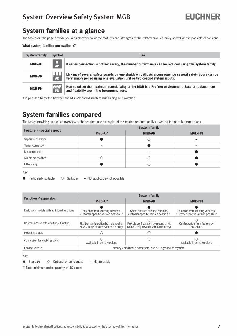
System families at a glanceThe tables on this page provide you a quick overview of the features and strengths of the related product family as well as the possible expansions.
What system families are available?
System family Symbol Use
MGB-AP AP If series connection is not necessary, the number of terminals can be reduced using this system family.
MGB-AR ARLinking of several safety guards on one shutdown path. As a consequence several safety doors can be very simply polled using one evaluation unit or two control system inputs.
MGB-PNPN
How to utilize the maximum functionality of the MGB in a Profinet environment. Ease of replacement and flexibility are in the foreground here.
It is possible to switch between the MGB-AP and MGB-AR families using DIP switches.
System families comparedThe tables provide you a quick overview of the features and strengths of the related product family as well as the possible expansions.
Feature / special aspect System family
MGB-AP MGB-AR MGB-PN
Separate operation –
Series connection – –
Bus connection – –
Simple diagnostics
Little wiring
Key:
Particularly suitable Suitable – Not applicable/not possible
Function / expansionSystem family
MGB-AP MGB-AR MGB-PN
Evaluation module with additional functions Selection from existing versions, customer-specific version possible *
Selection from existing versions, customer-specific version possible*
Selection from existing versions, customer-specific version possible*
Control module with additional functions Flexible configuration by means of kit MGB-C (only devices with cable entry)
Flexible configuration by means of kit MGB-C (only devices with cable entry)
Configuration from factory by EUCHNER
Mounting plates
Connection for enabling switchAvailable in some versions Available in some versions
Escape release Already contained in some sets, can be upgraded at any time.
Key:
Standard Optional or on request – Not possible
*) Note minimum order quantity of 50 pieces!
8
General
Subject to technical modifications; no responsibility is accepted for the accuracy of this information.
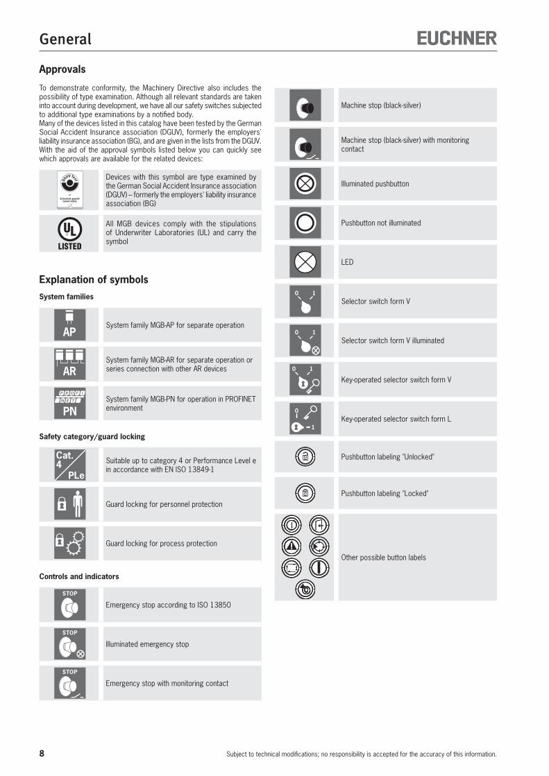
Explanation of symbolsSystem families
APSystem family MGB-AP for separate operation
ARSystem family MGB-AR for separate operation or series connection with other AR devices
PNSystem family MGB-PN for operation in PROFINET environment
Safety category/guard locking
Cat.4
PLe
Suitable up to category 4 or Performance Level e in accordance with EN ISO 13849-1
Guard locking for personnel protection
Guard locking for process protection
Controls and indicators
STOP
Emergency stop according to ISO 13850
STOP
Illuminated emergency stop
STOP
Emergency stop with monitoring contact
Machine stop (black-silver)
Machine stop (black-silver) with monitoring contact
Illuminated pushbutton
Pushbutton not illuminated
LED
0 1Selector switch form V
0 1Selector switch form V illuminated
0 1
Key-operated selector switch form V
0
1Key-operated selector switch form L
Pushbutton labeling "Unlocked"
Pushbutton labeling "Locked"
Other possible button labels
Approvals
To demonstrate conformity, the Machinery Directive also includes the possibility of type examination. Although all relevant standards are taken into account during development, we have all our safety switches subjected to additional type examinations by a notified body. Many of the devices listed in this catalog have been tested by the German Social Accident Insurance association (DGUV), formerly the employers' liability insurance association (BG), and are given in the lists from the DGUV. With the aid of the approval symbols listed below you can quickly see which approvals are available for the related devices:
Devices with this symbol are type examined by the German Social Accident Insurance association (DGUV) – formerly the employers' liability insurance association (BG)
All MGB devices comply with the stipulations of Underwriter Laboratories (UL) and carry the symbol
9
Safety System MGB-...-AP.../MGB-...-AR...
Subject to technical modifications; no responsibility is accepted for the accuracy of this information.
MG
B-A
RM
GB
-AP
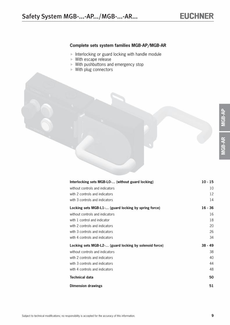
Interlocking sets MGB-L0-… (without guard locking) 10 - 15
without controls and indicators 10
with 2 controls and indicators 12
with 3 controls and indicators 14
Locking sets MGB-L1-… (guard locking by spring force) 16 - 36
without controls and indicators 16
with 1 control and indicator 18
with 2 controls and indicators 20
with 3 controls and indicators 26
with 4 controls and indicators 34
Locking sets MGB-L2-… (guard locking by solenoid force) 38 - 49
without controls and indicators 38
with 2 controls and indicators 40
with 3 controls and indicators 44
with 4 controls and indicators 48
Technical data 50
Dimension drawings 51
Complete sets system families MGB-AP/MGB-AR
Interlocking or guard locking with handle module With escape release With pushbuttons and emergency stop With plug connectors
10
Safety System MGB-...-AP.../MGB-...-AR...
Subject to technical modifications; no responsibility is accepted for the accuracy of this information.
Cat.4
PLe
Ordering table
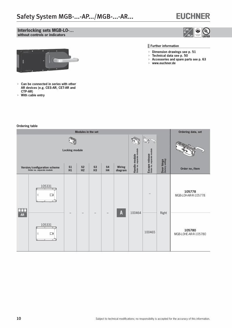
Can be connected in series with other AR devices (e.g. CES-AR, CET-AR and CTP-AR)
With cable entry
Further information
Dimension drawings see p. 51 Technical data see p. 50 Accessories and spare parts see p. 63 www.euchner.de
Interlocking sets MGB-L0-… without controls or indicators
Modules in the set Ordering data, set
Locking module
Han
dle
mod
ule
Ord
er n
o. s
epar
ate
mod
ule
Esca
pe r
elea
se
Ord
er n
o. s
epar
ate
mod
ule
Doo
r hi
nge
(fac
tory
set
ting)
Version/configuration schemeOrder no. separate module
S1H1
S2H2
S3H3
S4H4
Wiring diagram Order no./item
AR
105331
– – – – A 100464
–
Right
105778 MGB-L0H-AR-R-105778
105331
100465 105780 MGB-L0HE-AR-R-105780
11
Safety System MGB-...-AP.../MGB-...-AR...
Subject to technical modifications; no responsibility is accepted for the accuracy of this information.
MGB-L0...
MG
B-A
RM
GB
-AP
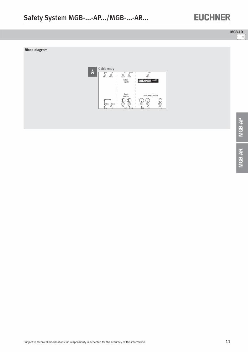
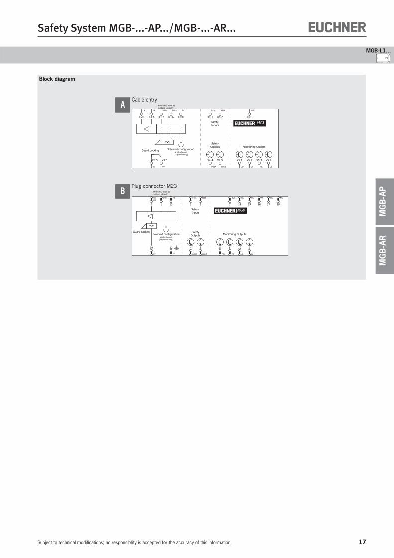
Block diagram
SafetyOutputs
Safety Inputs
Monitoring Outputs
MGB
FI1A
X4:1
FI1B
X4:2
RST
X4:6
FO1A
X4:4
FO1B
X4:5
OD
X5:1
OT
X5:2
OI
X5:4
0V
X5:5
0V
X3:5
UA
X3:4
UB
X5:6
Cable entryA
12
Safety System MGB-...-AP.../MGB-...-AR...
Subject to technical modifications; no responsibility is accepted for the accuracy of this information.
Cat.4
PLe
Ordering table for complete sets
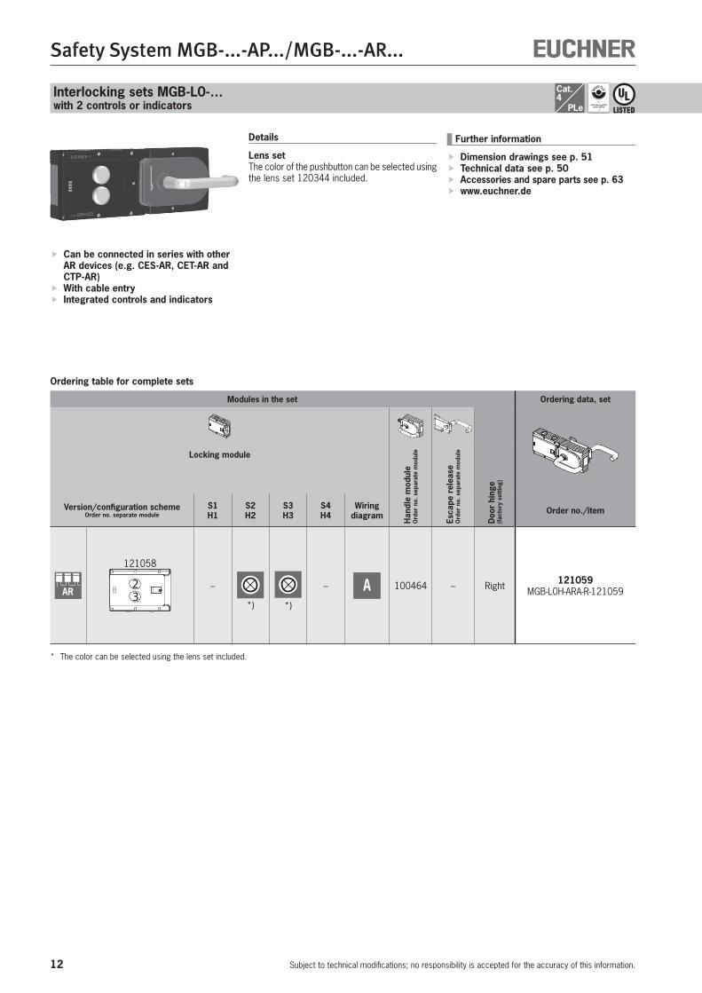
Can be connected in series with other AR devices (e.g. CES-AR, CET-AR and CTP-AR)
With cable entry Integrated controls and indicators
Interlocking sets MGB-L0-… with 2 controls or indicators
Details
Lens setThe color of the pushbutton can be selected using the lens set 120344 included.
Modules in the set Ordering data, set
Locking module
Han
dle
mod
ule
Ord
er n
o. s
epar
ate
mod
ule
Esca
pe r
elea
se
Ord
er n
o. s
epar
ate
mod
ule
Doo
r hi
nge
(fac
tory
set
ting)
Version/configuration schemeOrder no. separate module
S1H1
S2H2
S3H3
S4H4
Wiring diagram Order no./item
AR
121058
23
–
*) *)
– A 100464 – Right 121059 MGB-L0H-ARA-R-121059
* The color can be selected using the lens set included.
Further information
Dimension drawings see p. 51 Technical data see p. 50 Accessories and spare parts see p. 63 www.euchner.de

13
Safety System MGB-...-AP.../MGB-...-AR...
Subject to technical modifications; no responsibility is accepted for the accuracy of this information.
MGB-L0...
MG
B-A
RM
GB
-AP
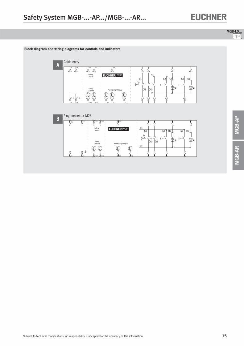
Block diagram and wiring diagram for controls and indicators
23
SafetyOutputs
Safety Inputs
Monitoring Outputs
H3S3
0V
UA
S2 H2MGB
FI1A
X4:1
FI1B
X4:2
RST
X4:6
FO1A
X4:4
FO1B
X4:5
OD
X5:1
OT
X5:2
OI
X5:4 X2:7 X3:2
X3:1 X3:3
0V
X5:5
0V
X3:5
UA
X3:4
UB
X5:6
Cable entryA

14
Safety System MGB-...-AP.../MGB-...-AR...
Subject to technical modifications; no responsibility is accepted for the accuracy of this information.
Cat.4
PLe
Interlocking sets MGB-L0-… with 3 controls or indicators
Ordering table
Can be connected in series with other AR devices (e.g. CES-AR, CET-AR and CTP-AR)
With cable entry or plug connector Integrated controls and indicators
Further information
Dimension drawings see p. 51 Technical data see p. 50 Accessories and spare parts see p. 63 www.euchner.de
Details
Emergency stop with monitoring contactAdditional normally open contact in the emer-gency stop, e.g. as monitoring contact for the control system.Lens setThe color of the pushbutton can be selected using the lens set 120344 included.Adhesive labelsDevices with adhesive labels have pre-formed recesses. The adhesive labels enclosed (stan-dard size 12.5 x 27 mm) can be affixed in these recesses.
Modules in the set Ordering data, set
Locking module
Han
dle
mod
ule
Ord
er n
o. s
epar
ate
mod
ule
Esca
pe r
elea
se
Ord
er n
o. s
epar
ate
mod
ule
Doo
r hi
nge
(fac
tory
set
ting)
Version/configuration schemeOrder no. separate module
S1H1
S2H2
S3H3
S4H4
Wiring diagram Order no./item
AR
121232
1 23
STOP
*) *)
– A
100464
100465
Right
121233 MGB-L0HE-ARA-R-121233
121253
1 23
Incl. adhesive labels–
121254 MGB-L0H-ARA-R-121254
121259
1 23
Incl. adhesive labels
106619 Left 121260 MGB-L0H-ARA-L-121260
116300
321
Incl. adhesive labels STOP
ye wh
– B
111157
100465
Right 110691 MGB-L0HE-ARA-R-110691
116302
312
Incl. adhesive labels
111158 Left 110692 MGB-L0HE-ARA-L-110692
* The color can be selected using the lens set included.
15
Safety System MGB-...-AP.../MGB-...-AR...
Subject to technical modifications; no responsibility is accepted for the accuracy of this information.
MGB-L0...
MG
B-A
RM
GB
-AP
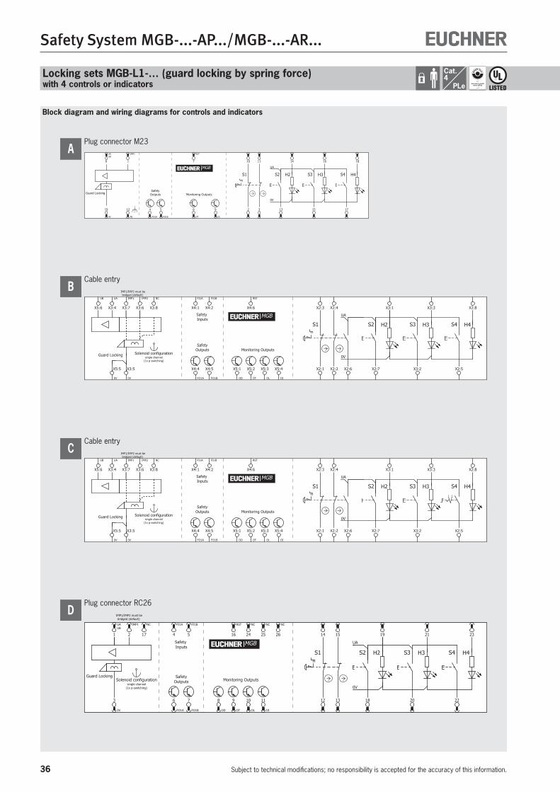
Block diagram and wiring diagrams for controls and indicators
Cable entry
SafetyOutputs
Safety Inputs
Monitoring Outputs
X2:1 X2:6
H2 H3S2 S3
0V
UA
S1
FI1A
X4:1
FI1B
X4:2
RST
X4:6
FO1A
X4:4
FO1B
X4:5
OD
X5:1
OT
X5:2
OI
X5:4
0V
X5:5
0V
X3:5
UA
X3:4
UB
X5:6 X3:3X2:3 X2:4
X2:2 X2:7 X3:2
X3:1
MGB
A
Plug connector M23
Monitoring Outputs
Safety Inputs S1 S2 S3H2 H3
UA
0V
SafetyOutputs
13
UAUB
6 1811
17
16
4
FO1A
5
FO1B
RST
7
8
OT
9
OI
19
0V
10
14
12
FE
15
FI1A
2
FI1B
3
NC
1
MGB
B
1 23

16
Safety System MGB-...-AP.../MGB-...-AR...
Subject to technical modifications; no responsibility is accepted for the accuracy of this information.
Cat.4
PLe
Ordering table
Can be connected in series with other AR devices (e.g. CES-AR, CET-AR and CTP-AR)
With cable entry or plug connector
Further information
Dimension drawings see p. 51 Technical data see p. 50 Accessories and spare parts see p. 63 www.euchner.de
Locking sets MGB-L1-… (guard locking by spring force)without control or indicator
Modules in the set Ordering data, set
Locking module
Han
dle
mod
ule
Ord
er n
o. s
epar
ate
mod
ule
Esca
pe r
elea
se
Ord
er n
o. s
epar
ate
mod
ule
Doo
r hi
nge
(fac
tory
set
ting)
Version/configuration schemeOrder no. separate module
S1H1
S2H2
S3H3
S4H4
Wiring diagram Order no./item
AR
104302
– – – –
A
100464
100465
Right
105784 MGB-L1HE-AR-R-105784
–
105782 MGB-L1H-AR-R-105782
111071
B
111070 MGB-L1H-ARA-R-111070
111074
106619 Left 111073 MGB-L1H-ARA-L-111073
17
Safety System MGB-...-AP.../MGB-...-AR...
Subject to technical modifications; no responsibility is accepted for the accuracy of this information.
MGB-L1...
MG
B-A
RM
GB
-AP
Block diagram
IMP1/IMP2 must bebridged (default)
SafetyOutputs Monitoring Outputs
Safety Inputs
Guard Locking
| |
Solenoid configurationsingle channel
(1x p-switching)
IMP1
X3:7
FO1B
X4:5
UA
X3:4
OI
X5:4
IMP2
X3:6
FI1A
X4:1
FI1B
X4:2
FO1A
X4:4
OD
X5:1
RST
X4:6
OT
X5:2
OL
X5:3
UB
X5:6
0V
X5:5
0V
X3:5
NC
X3:8
MGB
Cable entryA
SafetyOutputs
Safety Inputs
Monitoring OutputsGuard Locking
IMP1/IMP2 must bebridged (default)
Solenoid configurationsingle channel
(1x p-switching)
FI1A
2
FI1B
3
RST
7
4
FO1A
5
FO1B
11
OD
8
OT
10
OL
9
OI
UAUB
6
NC
13
19
0V
IMP1
1
12
FE
NC
14
NC
15
NC
16
NC
17
NC
18
MGB
Plug connector M23B
18
Safety System MGB-...-AP.../MGB-...-AR...
Subject to technical modifications; no responsibility is accepted for the accuracy of this information.
Cat.4
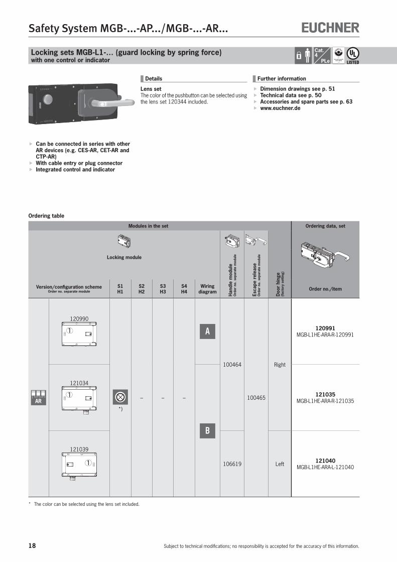
PLeLocking sets MGB-L1-… (guard locking by spring force)with one control or indicator
Ordering table
Can be connected in series with other AR devices (e.g. CES-AR, CET-AR and CTP-AR)
With cable entry or plug connector Integrated control and indicator
Details
Lens setThe color of the pushbutton can be selected using the lens set 120344 included.
Modules in the set Ordering data, set
Locking module
Han
dle
mod
ule
Ord
er n
o. s
epar
ate
mod
ule
Esca
pe r
elea
se
Ord
er n
o. s
epar
ate
mod
ule
Doo
r hi
nge
(fac
tory
set
ting)
Version/configuration schemeOrder no. separate module
S1H1
S2H2
S3H3
S4H4
Wiring diagram Order no./item
AR
120990
1
*)
– – –
A
100464
100465
Right
120991 MGB-L1HE-ARA-R-120991
121034
1
B
121035 MGB-L1HE-ARA-R-121035
121039
1 106619 Left 121040 MGB-L1HE-ARA-L-121040
* The color can be selected using the lens set included.
Further information
Dimension drawings see p. 51 Technical data see p. 50 Accessories and spare parts see p. 63 www.euchner.de
19
Safety System MGB-...-AP.../MGB-...-AR...
Subject to technical modifications; no responsibility is accepted for the accuracy of this information.
MGB-L1...
MG
B-A
RM
GB
-AP
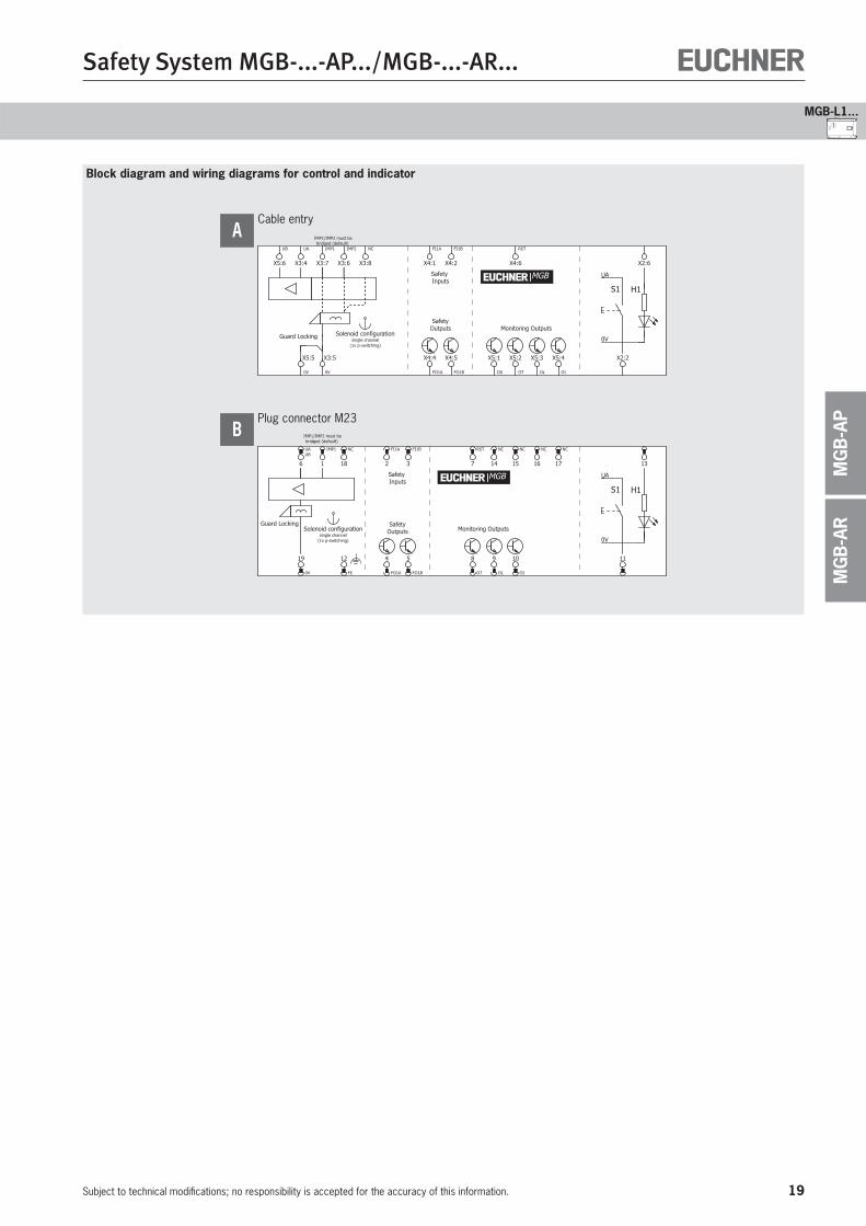
Block diagram and wiring diagrams for control and indicator
1
Cable entry
Monitoring Outputs
Safety Inputs
H1
0V
UA
S1
SafetyOutputs
IMP1/IMP2 must bebridged (default)
Guard Locking
| |
Solenoid configurationsingle channel
(1x p-switching)
OI
X5:4
X2:6
FI1A
X4:1
FI1B
X4:2
FO1A
X4:4
FO1B
X4:5
RST
X4:6
OT
X5:2
OL
X5:3 X2:2
OD
X5:1
IMP1
X3:7
UA
X3:4
IMP2
X3:6
UB
X5:6
0V
X5:5
0V
X3:5
NC
X3:8
MGB
A
Plug connector M23
Monitoring Outputs0V
UA
S1 H1
12
FE
SafetyOutputs
Safety Inputs
Guard Locking
IMP1/IMP2 must bebridged (default)
Solenoid configurationsingle channel
(1x p-switching)
RST
7
9
OL
10
OI
11
13
8
OT
NC
14
NC
15
NC
16
NC
17
FI1A
2
FI1B
3
4
FO1A
5
FO1B
UAUB
6
NC
18
19
0V
IMP1
1
MGB
B
20
Safety System MGB-...-AP.../MGB-...-AR...
Subject to technical modifications; no responsibility is accepted for the accuracy of this information.
Cat.4
PLe
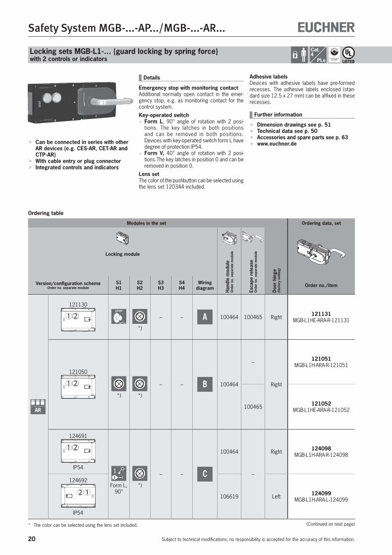
Locking sets MGB-L1-… (guard locking by spring force)with 2 controls or indicators
Ordering table
Can be connected in series with other AR devices (e.g. CES-AR, CET-AR and CTP-AR)
With cable entry or plug connector Integrated controls and indicators
Details
Emergency stop with monitoring contactAdditional normally open contact in the emer-gency stop, e.g. as monitoring contact for the control system.Key-operated switch
Form L, 90° angle of rotation with 2 posi-tions. The key latches in both positions and can be removed in both positions. Devices with key-operated switch form L have degree of protection IP54.
Form V, 40° angle of rotation with 2 posi-tions.The key latches in position 0 and can be removed in position 0.
Lens setThe color of the pushbutton can be selected using the lens set 120344 included.
(Continued on next page)
Modules in the set Ordering data, set
Locking module
Han
dle
mod
ule
Ord
er n
o. s
epar
ate
mod
ule
Esca
pe r
elea
se
Ord
er n
o. s
epar
ate
mod
ule
Doo
r hi
nge
(fac
tory
set
ting)
Version/configuration schemeOrder no. separate module
S1H1
S2H2
S3H3
S4H4
Wiring diagram Order no./item
AR
121130
1 2STOP
*)
– – A 100464 100465 Right 121131 MGB-L1HE-ARA-R-121131
121050
1 2
*) *)
– – B 100464
–
Right
121051 MGB-L1H-ARA-R-121051
100465 121052 MGB-L1HE-ARA-R-121052
124691
1 2
IP54 0
1
Form L,90°
*)
– – C
100464
–
Right 124098 MGB-L1H-ARA-R-124098
124692
2 1
IP54
106619 Left 124099 MGB-L1H-ARA-L-124099
* The color can be selected using the lens set included.
Adhesive labelsDevices with adhesive labels have pre-formed recesses. The adhesive labels enclosed (stan-dard size 12.5 x 27 mm) can be affixed in these recesses.
Further information
Dimension drawings see p. 51 Technical data see p. 50 Accessories and spare parts see p. 63 www.euchner.de
21
Safety System MGB-...-AP.../MGB-...-AR...
Subject to technical modifications; no responsibility is accepted for the accuracy of this information.
MGB-L1...
MG
B-A
RM
GB
-AP
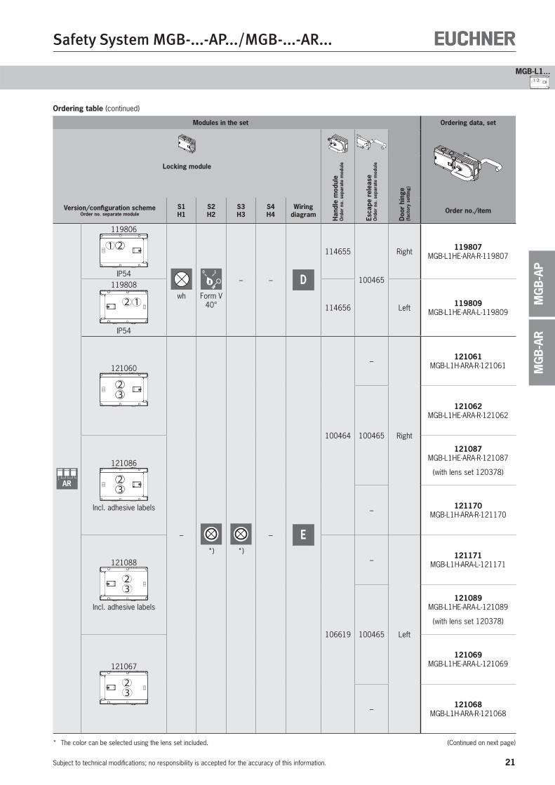
1 2
Ordering table (continued)
Modules in the set Ordering data, set
Locking module
Han
dle
mod
ule
Ord
er n
o. s
epar
ate
mod
ule
Esca
pe r
elea
se
Ord
er n
o. s
epar
ate
mod
ule
Doo
r hi
nge
(fac
tory
set
ting)
Version/configuration schemeOrder no. separate module
S1H1
S2H2
S3H3
S4H4
Wiring diagram Order no./item
AR
119806
1 2
IP54
wh
0 1
Form V 40°
– – D
114655
100465
Right 119807 MGB-L1HE-ARA-R-119807
119808
2 1
IP54
114656 Left 119809 MGB-L1HE-ARA-L-119809
121060
23
–
*) *)
– E
100464
–
Right
121061 MGB-L1H-ARA-R-121061
100465
121062 MGB-L1HE-ARA-R-121062
121086
23
Incl. adhesive labels
121087 MGB-L1HE-ARA-R-121087
(with lens set 120378)
– 121170 MGB-L1H-ARA-R-121170
121088
32
Incl. adhesive labels
106619
–
Left
121171 MGB-L1H-ARA-L-121171
100465
121089 MGB-L1HE-ARA-L-121089
(with lens set 120378)
121067
32
121069 MGB-L1HE-ARA-L-121069
– 121068 MGB-L1H-ARA-R-121068
* The color can be selected using the lens set included. (Continued on next page)
22
Safety System MGB-...-AP.../MGB-...-AR...
Subject to technical modifications; no responsibility is accepted for the accuracy of this information.
Cat.4
PLe
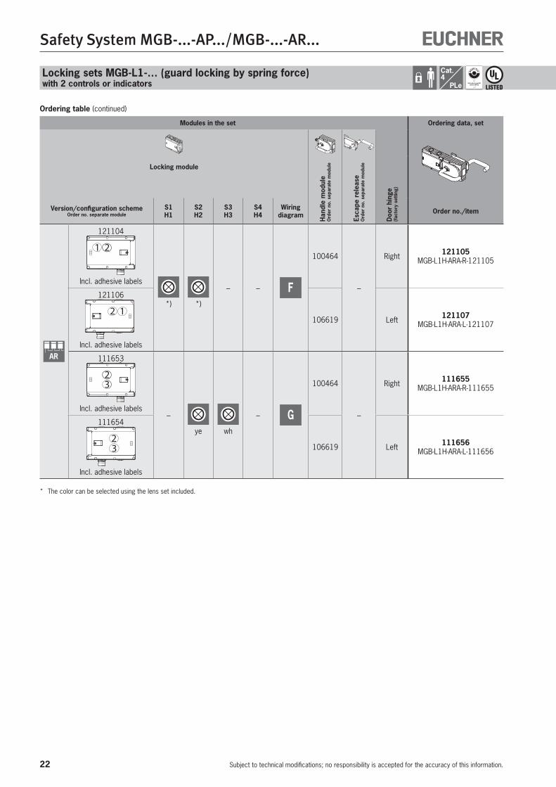
Ordering table (continued)
Locking sets MGB-L1-… (guard locking by spring force)with 2 controls or indicators
Modules in the set Ordering data, set
Locking module
Han
dle
mod
ule
Ord
er n
o. s
epar
ate
mod
ule
Esca
pe r
elea
se
Ord
er n
o. s
epar
ate
mod
ule
Doo
r hi
nge
(fac
tory
set
ting)
Version/configuration schemeOrder no. separate module
S1H1
S2H2
S3H3
S4H4
Wiring diagram Order no./item
AR
121104
21
Incl. adhesive labels
*) *)
– – F
100464
–
Right 121105 MGB-L1H-ARA-R-121105
121106
12
Incl. adhesive labels
106619 Left 121107 MGB-L1H-ARA-L-121107
111653
32
Incl. adhesive labels–
ye wh
– G
100464
–
Right 111655 MGB-L1H-ARA-R-111655
111654
32
Incl. adhesive labels
106619 Left 111656 MGB-L1H-ARA-L-111656
* The color can be selected using the lens set included.
23
Safety System MGB-...-AP.../MGB-...-AR...
Subject to technical modifications; no responsibility is accepted for the accuracy of this information.
MGB-L1...
MG
B-A
RM
GB
-AP
1 2
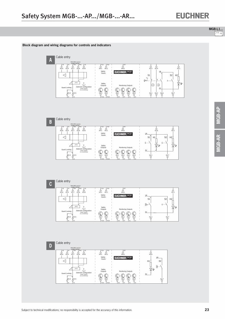
Block diagram and wiring diagrams for controls and indicators
Cable entry
SafetyOutputs Monitoring Outputs
Safety Inputs
H1
0V
UA
S2
IMP1/IMP2 must bebridged (default)
Guard Locking
| |
Solenoid configurationsingle channel
(1x p-switching)
OI
X5:4
X2:6
FI1A
X4:1
FI1B
X4:2
FO1A
X4:4
FO1B
X4:5
RST
X4:6
OT
X5:2
OL
X5:3 X2:7
OD
X5:1
IMP1
X3:7
UA
X3:4
IMP2
X3:6
UB
X5:6
0V
X5:5
0V
X3:5
NC
X3:8
MGB
D
Cable entry
SafetyOutputs Monitoring Outputs
Safety Inputs
H2
0V
UA
S1 S2
IMP1/IMP2 must bebridged (default)
Guard Locking
| |
Solenoid configurationsingle channel
(1x p-switching)
OI
X5:4 X2:7
X3:1
FI1A
X4:1
FI1B
X4:2
FO1A
X4:4
FO1B
X4:5
RST
X4:6
OT
X5:2
OL
X5:3 X2:1
OD
X5:1
IMP1
X3:7
UA
X3:4
IMP2
X3:6
UB
X5:6
0V
X5:5
0V
X3:5
NC
X3:8
MGB
C
Cable entry
Monitoring Outputs
Safety Inputs
H2S2
0V
UA
S1 H1
SafetyOutputs
IMP1/IMP2 must bebridged (default)
Guard Locking
| |
Solenoid configurationsingle channel
(1x p-switching)
X3:1
OI
X5:4 X2:7
X2:6
FI1A
X4:1
FI1B
X4:2
FO1A
X4:4
FO1B
X4:5
RST
X4:6
OT
X5:2
OL
X5:3 X2:1
OD
X5:1
IMP1
X3:7
UA
X3:4
IMP2
X3:6
UB
X5:6
0V
X5:5
0V
X3:5
NC
X3:8
MGB
B
Cable entry
Monitoring Outputs
Safety Inputs
H2S2
0V
UA
S1
SafetyOutputs
IMP1/IMP2 must bebridged (default)
Guard Locking
| |
Solenoid configurationsingle channel
(1x p-switching)
X2:3 X2:4
OI
X5:4 X2:2 X2:7
X3:1
FI1A
X4:1
FI1B
X4:2
FO1A
X4:4
FO1B
X4:5
RST
X4:6
OT
X5:2
OL
X5:3 X2:1
OD
X5:1 X2:6
IMP1
X3:7
UA
X3:4
IMP2
X3:6
UB
X5:6
0V
X5:5
0V
X3:5
NC
X3:8
MGB
A

24
Safety System MGB-...-AP.../MGB-...-AR...
Subject to technical modifications; no responsibility is accepted for the accuracy of this information.
Cat.4
PLe
Locking sets MGB-L1-… (guard locking by spring force)with 2 controls or indicators
Block diagram and wiring diagrams for controls and indicators
Plug connector M23
H3S3
0V
UA
S2 H2
Monitoring OutputsSafety
Outputs
Safety Inputs
Guard Locking
IMP1/IMP2 must bebridged (default)
Solenoid configurationsingle channel
(1x p-switching)
18
RST
7
8
OT
9
OI
15
16
17
NC
10
NC
11
NC
14
FI1A
2
FI1B
3
4
FO1A
5
FO1B
UAUB
6
NC
13
19
0V
IMP1
1
12
FE
MGB
G
Plug connector M23
H2S2
0V
UA
S1 H1
Monitoring OutputsSafety
Outputs
Safety Inputs
Guard Locking
IMP1/IMP2 must bebridged (default)
Solenoid configurationsingle channel
(1x p-switching)
18
RST
7
8
OT
9
OI
15
16
1710
OL
NC
11
NC
14
FI1A
2
FI1B
3
4
FO1A
5
FO1B
UAUB
6
NC
13
19
0V
IMP1
1
12
FE
MGB
F
Cable entry
Monitoring Outputs
Safety Inputs
H3S3
0V
UA
S2 H2
SafetyOutputs
IMP1/IMP2 must bebridged (default)
Guard Locking
| |
Solenoid configurationsingle channel
(1x p-switching)
X3:3
OI
X5:4 X3:2
X3:1
FI1A
X4:1
FI1B
X4:2
FO1A
X4:4
FO1B
X4:5
RST
X4:6
OT
X5:2
OL
X5:3 X2:7
OD
X5:1
IMP1
X3:7
UA
X3:4
IMP2
X3:6
UB
X5:6
0V
X5:5
0V
X3:5
NC
X3:8
MGB
E

25
Safety System MGB-...-AP.../MGB-...-AR...
Subject to technical modifications; no responsibility is accepted for the accuracy of this information.
MGB-L1...
MG
B-A
RM
GB
-AP
1 2
26
Safety System MGB-...-AP.../MGB-...-AR...
Subject to technical modifications; no responsibility is accepted for the accuracy of this information.
Cat.4
PLe
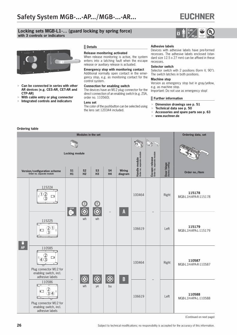
Locking sets MGB-L1-… (guard locking by spring force)with 3 controls or indicators
Ordering table
Can be connected in series with other AR devices (e.g. CES-AR, CET-AR and CTP-AR)
With cable entry or plug connector Integrated controls and indicators
Details
Release monitoring activatedWhen release monitoring is active, the system enters into a latching fault when the escape release or auxiliary release is actuated.Emergency stop with monitoring contactAdditional normally open contact in the emer-gency stop, e.g. as monitoring contact for the control system.Connection for enabling switchThe devices have an M12 plug connector for the direct connection of an enabling switch (e.g. ZSA, order no. 110560).Lens setThe color of the pushbutton can be selected using the lens set 120344 included.
Adhesive labelsDevices with adhesive labels have pre-formed recesses. The adhesive labels enclosed (stan-dard size 12.5 x 27 mm) can be affixed in these recesses.Selector switchSelector switch with 2 positions (form V, 90°). The switch latches in both positions.Machine stopVersion as emergency stop but in gray/yellow, e.g. as machine stop. Important: Do not use as emergency stop!
Further information
Dimension drawings see p. 51 Technical data see p. 50 Accessories and spare parts see p. 63 www.euchner.de
Modules in the set Ordering data, set
Locking module
Han
dle
mod
ule
Ord
er n
o. s
epar
ate
mod
ule
Esca
pe r
elea
se
Ord
er n
o. s
epar
ate
mod
ule
Doo
r hi
nge
(fac
tory
set
ting)
Version/configuration schemeOrder no. separate module
S1H1
S2H2
S3H3
S4H4
Wiring diagram Order no./item
AP
115224
1 23
STOP
wh wh
– A
100464
–
Right 115178 MGB-L1H-APA-R-115178
115225
32 1 106619 Left 115179
MGB-L1H-APA-L-115179
110585
423
Plug connector M12 for enabling switch, incl.
adhesive labels–
wh ye bu
B
100464
–
Right 110587 MGB-L1H-APA-R-110587
110586
432
Plug connector M12 for enabling switch, incl.
adhesive labels
106619 Left 110588 MGB-L1H-APA-L-110588
(Continued on next page)
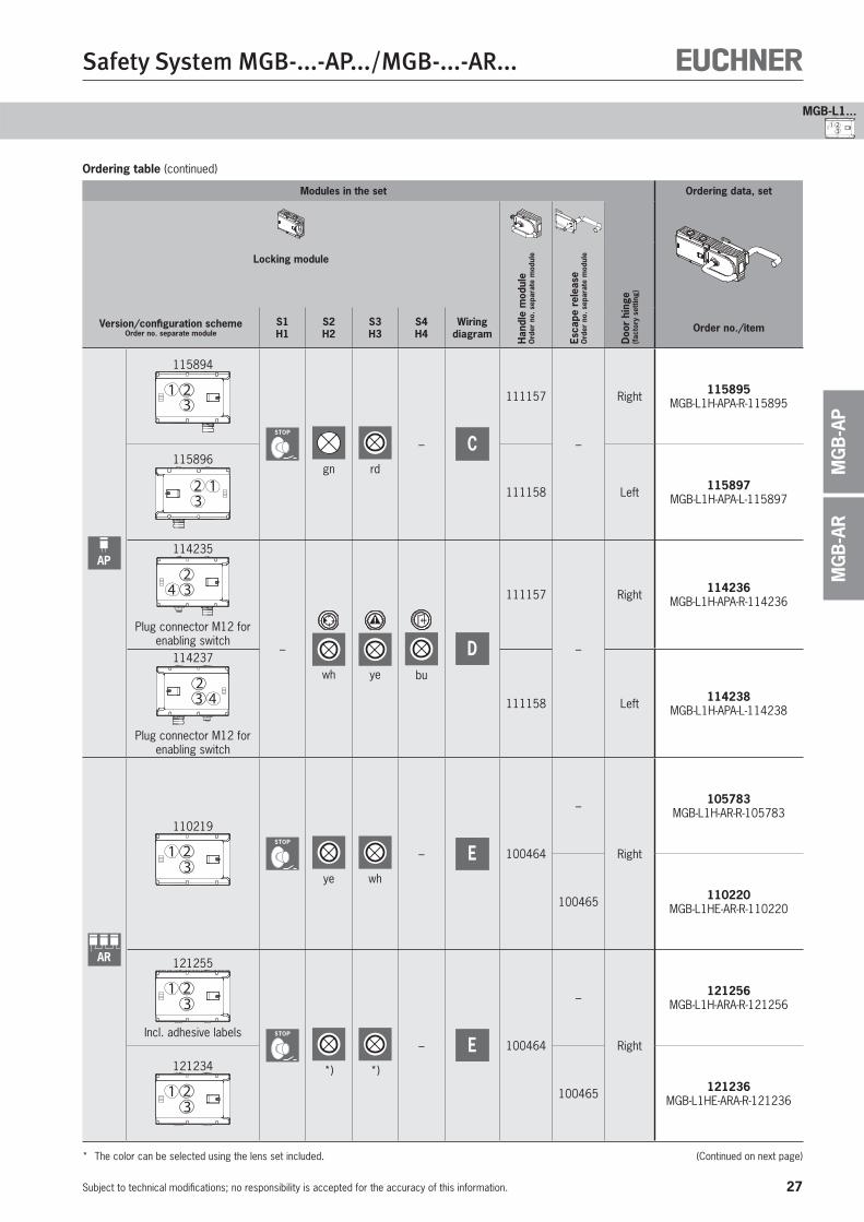
27
Safety System MGB-...-AP.../MGB-...-AR...
Subject to technical modifications; no responsibility is accepted for the accuracy of this information.
MGB-L1...
MG
B-A
RM
GB
-AP
1 23
Ordering table (continued)
Modules in the set Ordering data, set
Locking module
Han
dle
mod
ule
Ord
er n
o. s
epar
ate
mod
ule
Esca
pe r
elea
se
Ord
er n
o. s
epar
ate
mod
ule
Doo
r hi
nge
(fac
tory
set
ting)
Version/configuration schemeOrder no. separate module
S1H1
S2H2
S3H3
S4H4
Wiring diagram Order no./item
AP
115894
321
STOP
gn rd
– C
111157
–
Right 115895 MGB-L1H-APA-R-115895
115896
312 111158 Left 115897
MGB-L1H-APA-L-115897
114235
423
Plug connector M12 for enabling switch
–
wh ye bu
D
111157
–
Right 114236 MGB-L1H-APA-R-114236
114237
423
Plug connector M12 for
enabling switch
111158 Left 114238 MGB-L1H-APA-L-114238
AR
110219
1 23
STOP
ye wh
– E 100464
–
Right
105783 MGB-L1H-AR-R-105783
100465 110220 MGB-L1HE-AR-R-110220
121255
1 23
Incl. adhesive labels STOP
*) *)
– E 100464
–
Right
121256 MGB-L1H-ARA-R-121256
121234
1 23
100465 121236 MGB-L1HE-ARA-R-121236
* The color can be selected using the lens set included. (Continued on next page)
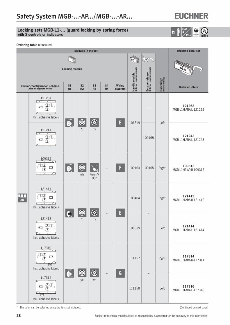
28
Safety System MGB-...-AP.../MGB-...-AR...
Subject to technical modifications; no responsibility is accepted for the accuracy of this information.
Cat.4
PLe
Modules in the set Ordering data, set
Locking module
Han
dle
mod
ule
Ord
er n
o. s
epar
ate
mod
ule
Esca
pe r
elea
se
Ord
er n
o. s
epar
ate
mod
ule
Doo
r hi
nge
(fac
tory
set
ting)
Version/configuration schemeOrder no. separate module
S1H1
S2H2
S3H3
S4H4
Wiring diagram Order no./item
AR
121261
32 1
Incl. adhesive labelsSTOP
*) *)
– E 106619
–
Left
121262 MGB-L1H-ARA-L-121262
121241
32 1 100465 121243
MGB-L1H-ARA-L-121243
109314
1 23
STOP
wh
0 1
Form V90°
– F 100464 100465 Right 109313 MGB-L1HE-AR-R-109313
121411
1 23
Incl. adhesive labels
*) *)
– E
100464
–
Right 121412 MGB-L1H-ARA-R-121412
121413
32 1
Incl. adhesive labels
106619 Left 121414 MGB-L1H-ARA-L-121414
117310
321
Incl. adhesive labels STOP
ye wh
– G
111157
–
Right 117314 MGB-L1H-ARA-R-117314
117312
312
Incl. adhesive labels
111158 Left 117316 MGB-L1H-ARA-L-117316
Ordering table (continued)
Locking sets MGB-L1-… (guard locking by spring force)with 3 controls or indicators
* The color can be selected using the lens set included. (Continued on next page)
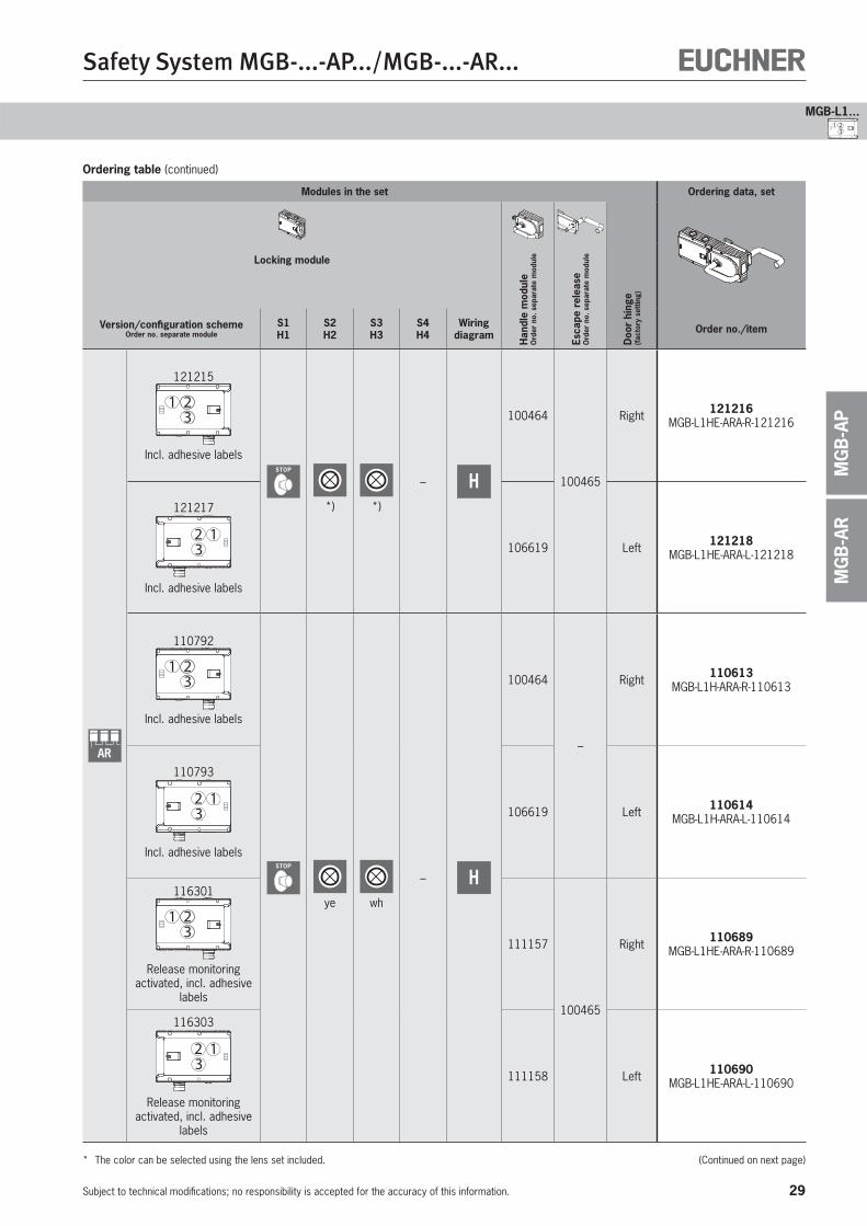
29
Safety System MGB-...-AP.../MGB-...-AR...
Subject to technical modifications; no responsibility is accepted for the accuracy of this information.
MGB-L1...
MG
B-A
RM
GB
-AP
Modules in the set Ordering data, set
Locking module
Han
dle
mod
ule
Ord
er n
o. s
epar
ate
mod
ule
Esca
pe r
elea
se
Ord
er n
o. s
epar
ate
mod
ule
Doo
r hi
nge
(fac
tory
set
ting)
Version/configuration schemeOrder no. separate module
S1H1
S2H2
S3H3
S4H4
Wiring diagram Order no./item
AR
121215
321
Incl. adhesive labelsSTOP
*) *)
– H
100464
100465
Right 121216 MGB-L1HE-ARA-R-121216
121217
312
Incl. adhesive labels
106619 Left 121218 MGB-L1HE-ARA-L-121218
110792
321
Incl. adhesive labels
STOP
ye wh
– H
100464
–
Right 110613 MGB-L1H-ARA-R-110613
110793
312
Incl. adhesive labels
106619 Left 110614 MGB-L1H-ARA-L-110614
116301
321
Release monitoring activated, incl. adhesive
labels
111157
100465
Right 110689 MGB-L1HE-ARA-R-110689
116303
312
Release monitoring activated, incl. adhesive
labels
111158 Left 110690 MGB-L1HE-ARA-L-110690
* The color can be selected using the lens set included. (Continued on next page)
Ordering table (continued)
1 23
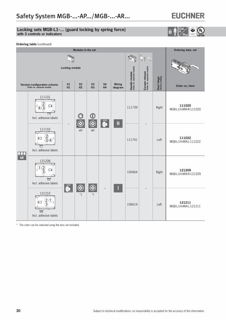
30
Safety System MGB-...-AP.../MGB-...-AR...
Subject to technical modifications; no responsibility is accepted for the accuracy of this information.
Cat.4
PLe
Modules in the set Ordering data, set
Locking module
Han
dle
mod
ule
Ord
er n
o. s
epar
ate
mod
ule
Esca
pe r
elea
se
Ord
er n
o. s
epar
ate
mod
ule
Doo
r hi
nge
(fac
tory
set
ting)
Version/configuration schemeOrder no. separate module
S1H1
S2H2
S3H3
S4H4
Wiring diagram Order no./item
AR
111101
423
Incl. adhesive labels
–
wh wh
STOP
H
111739
–
Right 111020 MGB-L1H-ARA-R-111020
111103
423
Incl. adhesive labels
111741 Left 111022 MGB-L1H-ARA-L-111022
121208
321
Incl. adhesive labelsSTOP
*) *)
– I
100464
–
Right 121209 MGB-L1H-ARA-R-121209
121210
312
Incl. adhesive labels
106619 Left 121211 MGB-L1H-ARA-L-121211
* The color can be selected using the lens set included.
Ordering table (continued)
Locking sets MGB-L1-… (guard locking by spring force)with 3 controls or indicators
31
Safety System MGB-...-AP.../MGB-...-AR...
Subject to technical modifications; no responsibility is accepted for the accuracy of this information.
MGB-L1...
MG
B-A
RM
GB
-AP
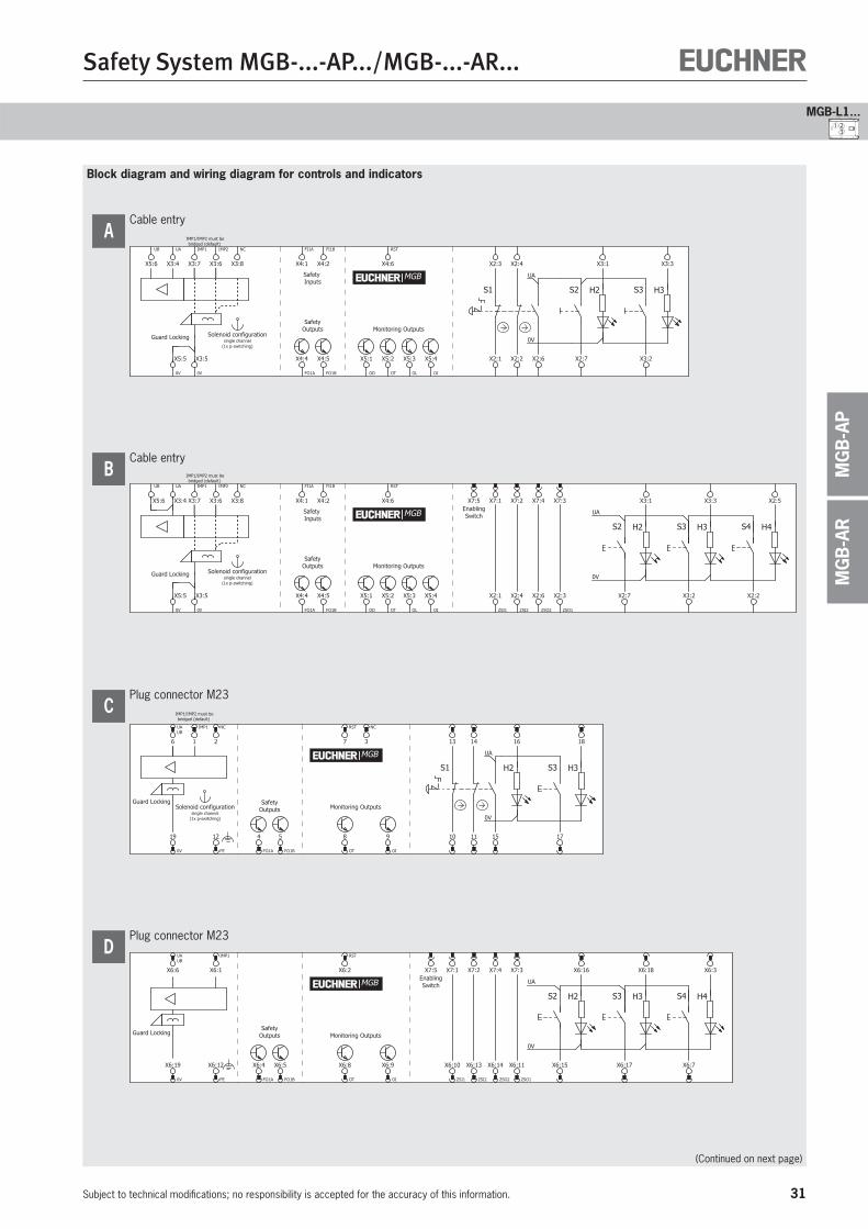
Block diagram and wiring diagram for controls and indicators
Cable entry
Monitoring Outputs
Safety Inputs
H2 H3S2 S3
0V
UA
S1
SafetyOutputs
IMP1/IMP2 must bebridged (default)
Guard Locking
| |
Solenoid configurationsingle channel
(1x p-switching)
X3:3X2:3 X2:4
OI
X5:4 X2:2 X2:7 X3:2
X3:1
FI1A
X4:1
FI1B
X4:2
FO1A
X4:4
FO1B
X4:5
RST
X4:6
OT
X5:2
OL
X5:3 X2:1
OD
X5:1 X2:6
IMP1
X3:7
UA
X3:4
IMP2
X3:6
UB
X5:6
0V
X5:5
0V
X3:5
NC
X3:8
MGB
A
Cable entry
Monitoring Outputs
Safety Inputs
H2 H3S2 S3 H4S4
UA
0V
SafetyOutputs
EnablingSwitch
IMP1/IMP2 must bebridged (default)
Guard Locking
| |
Solenoid configurationsingle channel
(1x p-switching)
FI1A
X4:1 X3:3 X2:5
OI
X5:4 X2:2X2:7 X3:2
X3:1
FI1B
X4:2
FO1A
X4:4
FO1B
X4:5
RST
X4:6
OT
X5:2
OL
X5:3
OD
X5:1
X7:5 X7:1 X7:2 X7:4 X7:3
ZSI1
X2:1
ZSI2
X2:4
ZSO2
X2:6
ZSO1
X2:3
IMP1
X3:7
IMP2
X3:6
0V
X5:5
0V
X3:5
NC
X3:8
UA
X3:4
UB
X5:6
MGB
B
Plug connector M23
H2 H3S3
0V
UA
S1
Monitoring OutputsSafety
OutputsGuard Locking
IMP1/IMP2 must bebridged (default)
Solenoid configurationsingle channel
(1x p-switching)
11
1813
17
16
RST
7
8
OT
10
14
159
OI
NC
3
4
FO1A
5
FO1B
UAUB
6
NC
2
19
0V
IMP1
1
12
FE
MGB
C
Plug connector M23
EnablingSwitch
SafetyOutputs Monitoring OutputsGuard Locking
H2 H3S2 S3 H4S4
UA
0V
MGB
X6:19
0V
UAUB
X6:6 X6:18 X6:3
X6:9
OI
X6:7X6:15 X6:17
X6:16
IMP1
X6:1
X6:4
FO1A
X6:5
FO1B
RST
X6:2
X6:12
FE
X6:8
OT
X6:10
ZSI1
X6:13
ZSI2
X6:14
ZSO2
X6:11
ZSO1
X7:5 X7:1 X7:2 X7:4 X7:3
D
(Continued on next page)
1 23
32
Safety System MGB-...-AP.../MGB-...-AR...
Subject to technical modifications; no responsibility is accepted for the accuracy of this information.
Cat.4
PLe
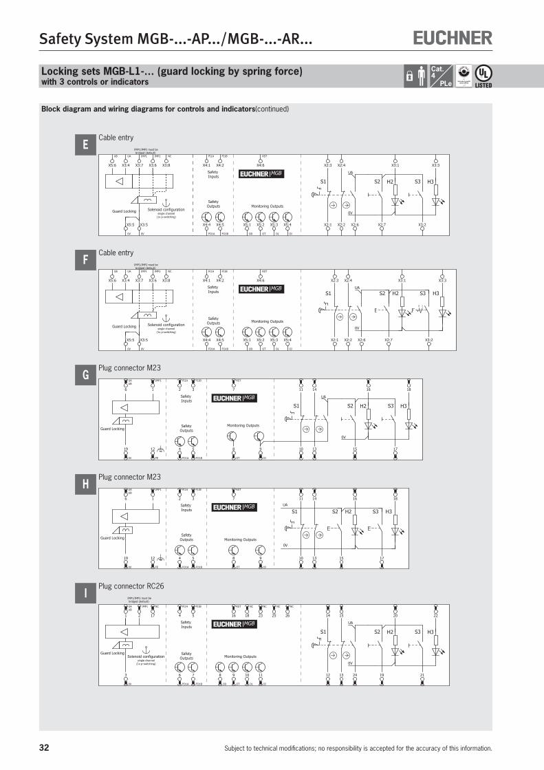
Block diagram and wiring diagrams for controls and indicators(continued)
Plug connector RC26
Monitoring Outputs
NC
26
H2 H3S2 S3
0V
UA
S1
SafetyOutputs
Safety Inputs
Guard Locking
IMP1/IMP2 must bebridged (default)
Solenoid configurationsingle channel
(1x p-switching)
UAUB
1 20
24
15
IMP1
2
6
FO1A
7
FO1B
RST
16
9
OT
11
OI
3
0V
12
14
13
FI1A
4
FI1B
5
NC
17
19 21
22
8
OD
10
OL
NC
18
NC
23
NC
25
MGB
I
Plug connector M23
SafetyOutputs Monitoring OutputsGuard Locking
Safety Inputs S1 S2 S3H2 H3
UA
0V
MGB
13
UAUB
6 1811
17
16
IMP1
1
4
FO1A
5
FO1B
RST
7
8
OT
9
OI
19
0V
10
14
12
FE
15
FI1A
2
FI1B
3
H
Plug connector M23
SafetyOutputs
Monitoring OutputsGuard Locking
Safety Inputs
18
12
FE
H2 H3S2 S3
0V
UA
S1
UAUB
6 16
9
OI
14
IMP1
1
4
FO1A
5
FO1B
RST
7
8
OT
19
0V
10
11
13
FI1A
2
FI1B
3
15 17
MGB
G
Cable entry
S1 S2 S3H2 H3
SafetyOutputs
Safety Inputs
Monitoring Outputs
10
IMP1/IMP2 must bebridged (default)
Guard Locking
| |
Solenoid configurationsingle channel
(1x p-switching)0V
UA
FI1A
X4:1
FI1B
X4:2
RST
X4:6
FO1A
X4:4
FO1B
X4:5
OD
X5:1
OT
X5:2
OL
X5:3
OI
X5:4 X2:1 X2:7 X3:2
X2:4 X3:1 X3:3
X2:2
X2:3
IMP1
X3:7
UA
X3:4
IMP2
X3:6
UB
X5:6
0V
X5:5
0V
X3:5
NC
X3:8
X2:6
MGB
F
Cable entry
Monitoring Outputs
Safety Inputs
H2 H3S2 S3
0V
UA
S1
SafetyOutputs
IMP1/IMP2 must bebridged (default)
Guard Locking
| |
Solenoid configurationsingle channel
(1x p-switching)
X3:3X2:3 X2:4
OI
X5:4 X2:2 X2:7 X3:2
X3:1
FI1A
X4:1
FI1B
X4:2
FO1A
X4:4
FO1B
X4:5
RST
X4:6
OT
X5:2
OL
X5:3 X2:1
OD
X5:1 X2:6
IMP1
X3:7
UA
X3:4
IMP2
X3:6
UB
X5:6
0V
X5:5
0V
X3:5
NC
X3:8
MGB
E
Locking sets MGB-L1-… (guard locking by spring force)with 3 controls or indicators

33
Safety System MGB-...-AP.../MGB-...-AR...
Subject to technical modifications; no responsibility is accepted for the accuracy of this information.
MGB-L1...
MG
B-A
RM
GB
-AP
1 23
34
Safety System MGB-...-AP.../MGB-...-AR...
Subject to technical modifications; no responsibility is accepted for the accuracy of this information.
Cat.4
PLe
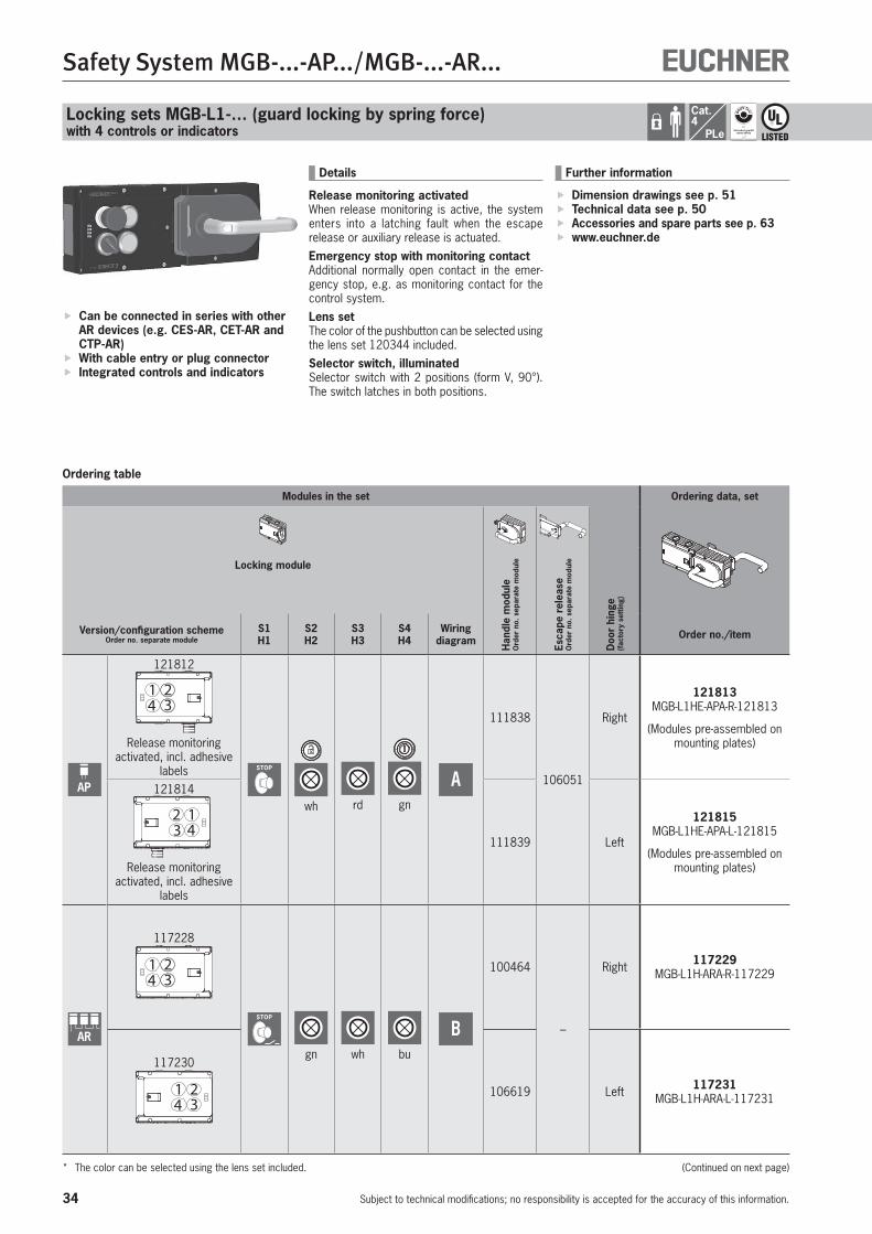
Locking sets MGB-L1-… (guard locking by spring force)with 4 controls or indicators
Ordering table
Can be connected in series with other AR devices (e.g. CES-AR, CET-AR and CTP-AR)
With cable entry or plug connector Integrated controls and indicators
Details
Release monitoring activatedWhen release monitoring is active, the system enters into a latching fault when the escape release or auxiliary release is actuated.Emergency stop with monitoring contactAdditional normally open contact in the emer-gency stop, e.g. as monitoring contact for the control system.Lens setThe color of the pushbutton can be selected using the lens set 120344 included.Selector switch, illuminatedSelector switch with 2 positions (form V, 90°). The switch latches in both positions.
Further information
Dimension drawings see p. 51 Technical data see p. 50 Accessories and spare parts see p. 63 www.euchner.de
Modules in the set Ordering data, set
Locking module
Han
dle
mod
ule
Ord
er n
o. s
epar
ate
mod
ule
Esca
pe r
elea
se
Ord
er n
o. s
epar
ate
mod
ule
Doo
r hi
nge
(fac
tory
set
ting)
Version/configuration schemeOrder no. separate module
S1H1
S2H2
S3H3
S4H4
Wiring diagram Order no./item
AP
121812
4 321
Release monitoring activated, incl. adhesive
labels STOP
wh rd gn
A
111838
106051
Right
121813 MGB-L1HE-APA-R-121813
(Modules pre-assembled on mounting plates)
121814
3 412
Release monitoring activated, incl. adhesive
labels
111839 Left
121815 MGB-L1HE-APA-L-121815
(Modules pre-assembled on mounting plates)
AR
117228
4 321
STOP
gn wh bu
B
100464
–
Right 117229 MGB-L1H-ARA-R-117229
117230
4 321 106619 Left 117231
MGB-L1H-ARA-L-117231
* The color can be selected using the lens set included. (Continued on next page)
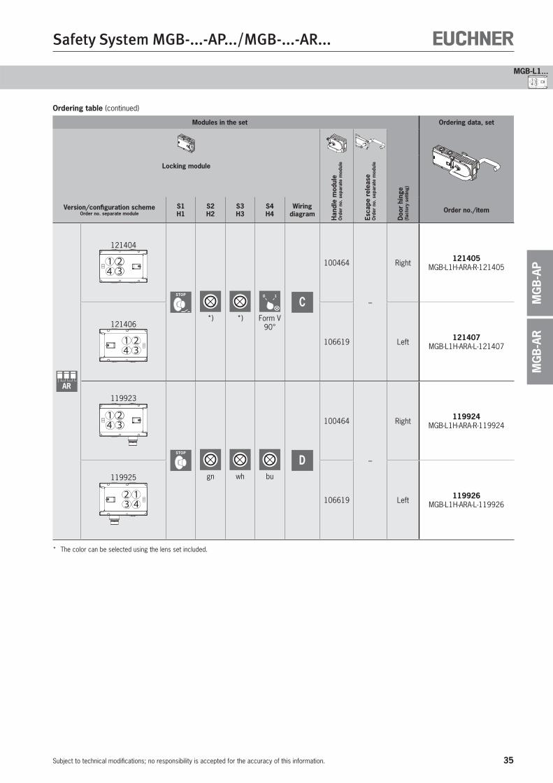
35
Safety System MGB-...-AP.../MGB-...-AR...
Subject to technical modifications; no responsibility is accepted for the accuracy of this information.
MGB-L1...
MG
B-A
RM
GB
-AP
4 321
Modules in the set Ordering data, set
Locking module
Han
dle
mod
ule
Ord
er n
o. s
epar
ate
mod
ule
Esca
pe r
elea
se
Ord
er n
o. s
epar
ate
mod
ule
Doo
r hi
nge
(fac
tory
set
ting)
Version/configuration schemeOrder no. separate module
S1H1
S2H2
S3H3
S4H4
Wiring diagram Order no./item
AR
121404
4 321
STOP
*) *)
0 1
Form V90°
C
100464
–
Right 121405 MGB-L1H-ARA-R-121405
121406
4 321 106619 Left 121407
MGB-L1H-ARA-L-121407
119923
4 321
STOP
gn wh bu
D
100464
–
Right 119924 MGB-L1H-ARA-R-119924
119925
4312
106619 Left 119926 MGB-L1H-ARA-L-119926
* The color can be selected using the lens set included.
Ordering table (continued)
36
Safety System MGB-...-AP.../MGB-...-AR...
Subject to technical modifications; no responsibility is accepted for the accuracy of this information.
Cat.4
PLe
Block diagram and wiring diagrams for controls and indicators
Locking sets MGB-L1-… (guard locking by spring force)with 4 controls or indicators
Plug connector M23
H2 H3
SafetyOutputs Monitoring Outputs
S2 S3
0V
UA
S1 H4
Guard Locking
S4
3
UAUB
6 1610
13 15
14
IMP1
1
4
FO1A
5
FO1B
RST
7
8
OT
9
OI
19
0V
2
11
12
FE
18
17
MGB
A
Cable entry
SafetyOutputs Monitoring Outputs
Safety Inputs
H2 H3S3
NC
X3:8
X2:6
S2 H4S4S1
IMP1/IMP2 must bebridged (default)
Guard Locking
| |
Solenoid configurationsingle channel
(1x p-switching)
UA
0V
X3:3
OI
X5:4 X3:2
X3:1
FI1A
X4:1
FI1B
X4:2
FO1A
X4:4
FO1B
X4:5
RST
X4:6
OT
X5:2
OL
X5:3
OD
X5:1 X2:7
X2:8
X2:5
X2:3 X2:4
X2:2X2:1
IMP1
X3:7
UA
X3:4
IMP2
X3:6
UB
X5:6
0V
X5:5
0V
X3:5
MGB
B
Cable entry
SafetyOutputs Monitoring Outputs
Safety Inputs
H3S3
0V
X3:5
NC
X3:8
H2S2
0V
UA
S1 S421
H4
IMP1/IMP2 must bebridged (default)
Guard Locking
| |
Solenoid configurationsingle channel
(1x p-switching)
X3:3
OI
X5:4 X3:2
FI1A
X4:1
FI1B
X4:2
FO1A
X4:4
FO1B
X4:5
RST
X4:6
OT
X5:2
OL
X5:3
OD
X5:1
X2:3 X2:4
X2:2 X2:7
X3:1
X2:1 X2:6 X2:5
X2:8
IMP1
X3:7
UA
X3:4
IMP2
X3:6
UB
X5:6
0V
X5:5
MGB
C
Plug connector RC26
Monitoring Outputs
NC
17
H2 H3S3
0V
UA
S2 H4S4S1
SafetyOutputs
Safety Inputs
Guard Locking
IMP1/IMP2 must bebridged (default)
Solenoid configurationsingle channel
(1x p-switching)
21
20
19
RST
16
9
OT
11
OI
12
15
1810
OL
22
2314
138
OD
NC
24
NC
25
NC
26
UAUB
1
IMP1
2
6
FO1A
7
FO1B
3
0V
FI1A
4
FI1B
5
MGB
D

37
Safety System MGB-...-AP.../MGB-...-AR...
Subject to technical modifications; no responsibility is accepted for the accuracy of this information.
MGB-L1...
MG
B-A
RM
GB
-AP
4 321
38
Safety System MGB-...-AP.../MGB-...-AR...
Subject to technical modifications; no responsibility is accepted for the accuracy of this information.
Cat.4
PLe
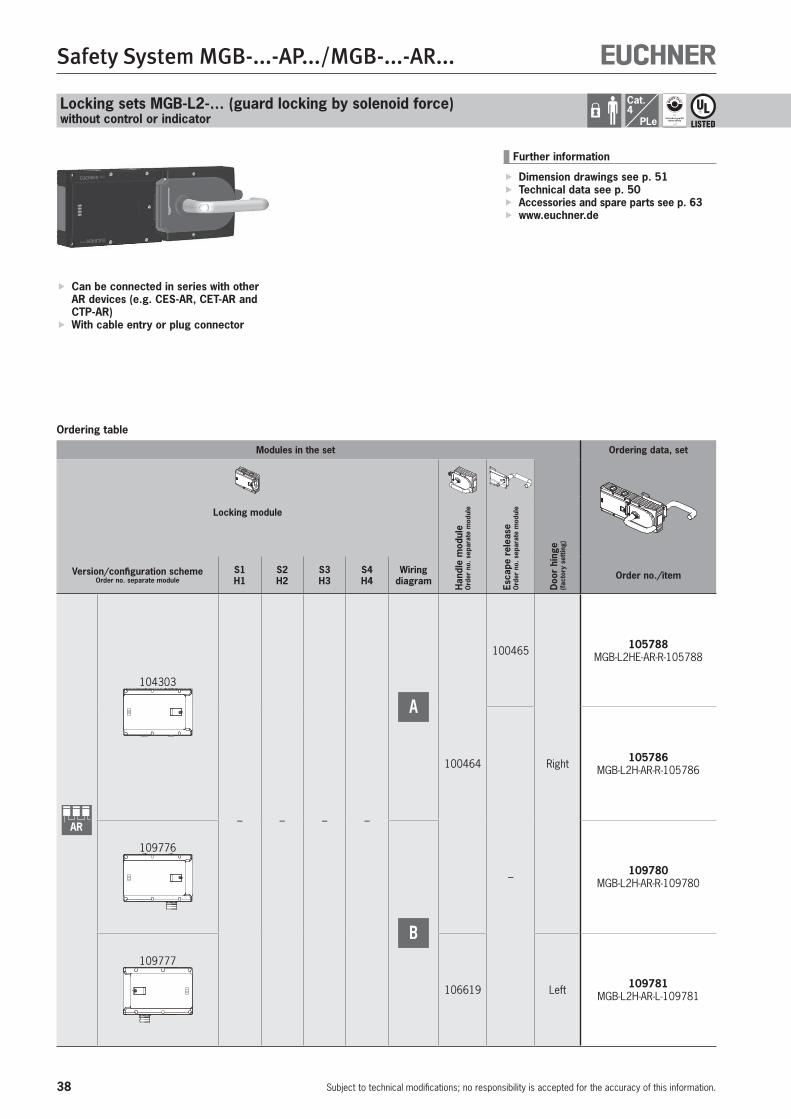
Locking sets MGB-L2-… (guard locking by solenoid force)without control or indicator
Ordering table
Can be connected in series with other AR devices (e.g. CES-AR, CET-AR and CTP-AR)
With cable entry or plug connector
Further information
Dimension drawings see p. 51 Technical data see p. 50 Accessories and spare parts see p. 63 www.euchner.de
Modules in the set Ordering data, set
Locking module
Han
dle
mod
ule
Ord
er n
o. s
epar
ate
mod
ule
Esca
pe r
elea
se
Ord
er n
o. s
epar
ate
mod
ule
Doo
r hi
nge
(fac
tory
set
ting)
Version/configuration schemeOrder no. separate module
S1H1
S2H2
S3H3
S4H4
Wiring diagram Order no./item
AR
104303
– – – –
A
100464
100465
Right
105788 MGB-L2HE-AR-R-105788
–
105786 MGB-L2H-AR-R-105786
109776
B
109780 MGB-L2H-AR-R-109780
109777
106619 Left 109781 MGB-L2H-AR-L-109781

39
Safety System MGB-...-AP.../MGB-...-AR...
Subject to technical modifications; no responsibility is accepted for the accuracy of this information.
MGB-L2...
MG
B-A
RM
GB
-AP
Block diagram
IMP1/IMP2 must bebridged (default)
SafetyOutputs Monitoring Outputs
Safety Inputs
Guard Locking
| |
Solenoid configurationsingle channel
(1x p-switching)
IMP1
X3:7
FO1B
X4:5
UA
X3:4
OI
X5:4
IMP2
X3:6
FI1A
X4:1
FI1B
X4:2
FO1A
X4:4
OD
X5:1
RST
X4:6
OT
X5:2
OL
X5:3
UB
X5:6
0V
X5:5
0V
X3:5
NC
X3:8
MGB
Cable entryA
SafetyOutputs
Safety Inputs
Monitoring OutputsGuard Locking
IMP1/IMP2 must bebridged (default)
Solenoid configurationsingle channel
(1x p-switching)
FI1A
2
FI1B
3
RST
7
4
FO1A
5
FO1B
11
OD
8
OT
10
OL
9
OI
UAUB
6
NC
13
19
0V
IMP1
1
12
FE
NC
14
NC
15
NC
16
NC
17
NC
18
MGB
Plug connector M23B
40
Safety System MGB-...-AP.../MGB-...-AR...
Subject to technical modifications; no responsibility is accepted for the accuracy of this information.
Cat.4
PLe
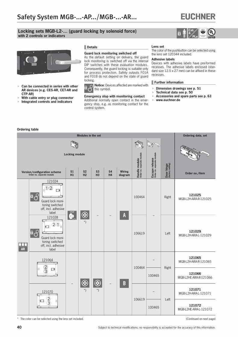
Locking sets MGB-L2-… (guard locking by solenoid force)with 2 controls or indicators
Ordering table
Can be connected in series with other AR devices (e.g. CES-AR, CET-AR and CTP-AR)
With cable entry or plug connector Integrated controls and indicators
Lens setThe color of the pushbutton can be selected using the lens set 120344 included.Adhesive labelsDevices with adhesive labels have pre-formed recesses. The adhesive labels enclosed (stan-dard size 12.5 x 27 mm) can be affixed in these recesses.
Further information
Dimension drawings see p. 51 Technical data see p. 50 Accessories and spare parts see p. 63 www.euchner.de
Details
Guard lock monitoring switched offAs the default setting on delivery, the guard lock monitoring is switched off via the internal DIP switches with these evaluation modules. Consequently, the guard locking is suitable only for process protection. Safety outputs FO1A and FO1B do not depend on the state of guard locking.
Notice: Devices affected are marked with this symbol.
Emergency stop with monitoring contactAdditional normally open contact in the emer-gency stop, e.g. as monitoring contact for the control system.
Modules in the set Ordering data, set
Locking module
Han
dle
mod
ule
Ord
er n
o. s
epar
ate
mod
ule
Esca
pe r
elea
se
Ord
er n
o. s
epar
ate
mod
ule
Doo
r hi
nge
(fac
tory
set
ting)
Version/configuration schemeOrder no. separate module
S1H1
S2H2
S3H3
S4H4
Wiring diagram Order no./item
AR
121024
1 2
STOP
*)
– – A
100464
–
Right 121025 MGB-L2H-ARA-R-121025
Guard lock moni-toring switched
off, incl. adhesive label
121028
2 1
106619 Left 121029 MGB-L2H-ARA-L-121029
Guard lock moni-toring switched
off, incl. adhesive label
121064
23
–
*) *)
– B
100464
–
Right
121065 MGB-L2H-ARA-R-121065
100465 121066 MGB-L2HE-ARA-R-121066
121070
32 106619
–
Left
121071 MGB-L2H-ARA-L-121071
100465 121072 MGB-L2HE-ARA-L-121072
* The color can be selected using the lens set included. (Continued on next page)
41
Safety System MGB-...-AP.../MGB-...-AR...
Subject to technical modifications; no responsibility is accepted for the accuracy of this information.
MGB-L2...
MG
B-A
RM
GB
-AP
1 2
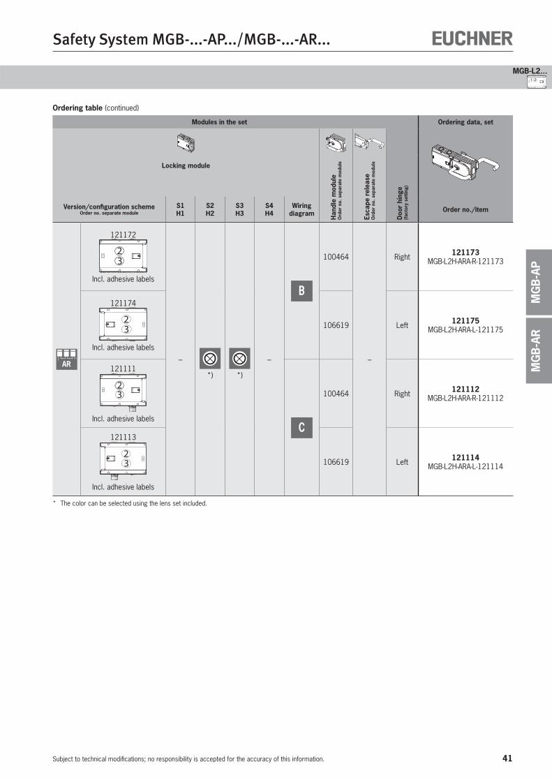
Ordering table (continued)
Modules in the set Ordering data, set
Locking module
Han
dle
mod
ule
Ord
er n
o. s
epar
ate
mod
ule
Esca
pe r
elea
se
Ord
er n
o. s
epar
ate
mod
ule
Doo
r hi
nge
(fac
tory
set
ting)
Version/configuration schemeOrder no. separate module
S1H1
S2H2
S3H3
S4H4
Wiring diagram Order no./item
AR
121172
23
Incl. adhesive labels
–
*) *)
–
B
100464
–
Right 121173 MGB-L2H-ARA-R-121173
121174
32
Incl. adhesive labels
106619 Left 121175 MGB-L2H-ARA-L-121175
121111
32
Incl. adhesive labelsC
100464 Right 121112 MGB-L2H-ARA-R-121112
121113
32
Incl. adhesive labels
106619 Left 121114 MGB-L2H-ARA-L-121114
* The color can be selected using the lens set included.
42
Safety System MGB-...-AP.../MGB-...-AR...
Subject to technical modifications; no responsibility is accepted for the accuracy of this information.
Cat.4
PLe
Locking sets MGB-L2-… (guard locking by solenoid force)with 2 controls or indicators
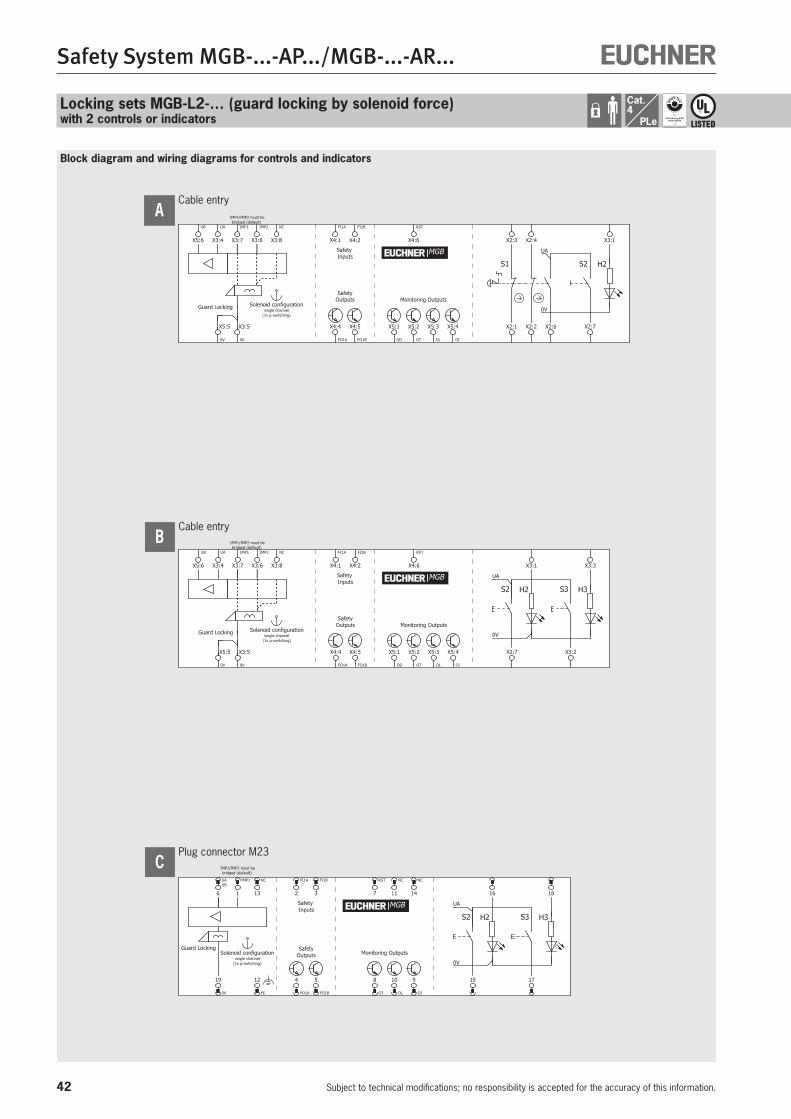
Block diagram and wiring diagrams for controls and indicators
Cable entry
Monitoring Outputs
Safety Inputs
H2S2
0V
UA
S1
SafetyOutputs
IMP1/IMP2 must bebridged (default)
Guard Locking
| |
Solenoid configurationsingle channel
(1x p-switching)
X2:3 X2:4
OI
X5:4 X2:2 X2:7
X3:1
FI1A
X4:1
FI1B
X4:2
FO1A
X4:4
FO1B
X4:5
RST
X4:6
OT
X5:2
OL
X5:3 X2:1
OD
X5:1 X2:6
IMP1
X3:7
UA
X3:4
IMP2
X3:6
UB
X5:6
0V
X5:5
0V
X3:5
NC
X3:8
MGB
A
Cable entry
Monitoring Outputs
Safety Inputs
H3S3
0V
UA
S2 H2
SafetyOutputs
IMP1/IMP2 must bebridged (default)
Guard Locking
| |
Solenoid configurationsingle channel
(1x p-switching)
X3:3
OI
X5:4 X3:2
X3:1
FI1A
X4:1
FI1B
X4:2
FO1A
X4:4
FO1B
X4:5
RST
X4:6
OT
X5:2
OL
X5:3 X2:7
OD
X5:1
IMP1
X3:7
UA
X3:4
IMP2
X3:6
UB
X5:6
0V
X5:5
0V
X3:5
NC
X3:8
MGB
B
Plug connector M23
Monitoring Outputs
H3S3
0V
UA
S2 H2
SafetyOutputs
Safety Inputs
Guard Locking
IMP1/IMP2 must bebridged (default)
Solenoid configurationsingle channel
(1x p-switching)
18
RST
7
10
OL
9
OI
15
16
178
OT
NC
11
NC
14
FI1A
2
FI1B
3
4
FO1A
5
FO1B
UAUB
6
NC
13
19
0V
IMP1
1
12
FE
MGB
C
43
Safety System MGB-...-AP.../MGB-...-AR...
Subject to technical modifications; no responsibility is accepted for the accuracy of this information.
MGB-L2...
MG
B-A
RM
GB
-AP
1 2
44
Safety System MGB-...-AP.../MGB-...-AR...
Subject to technical modifications; no responsibility is accepted for the accuracy of this information.
Cat.4
PLe
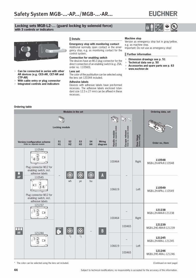
Locking sets MGB-L2-… (guard locking by solenoid force)with 3 controls or indicators
Ordering table
Can be connected in series with other AR devices (e.g. CES-AR, CET-AR and CTP-AR)
With cable entry or plug connector Integrated controls and indicators
Machine stopVersion as emergency stop but in gray/yellow, e.g. as machine stop. Important: Do not use as emergency stop!
Further information
Dimension drawings see p. 51 Technical data see p. 50 Accessories and spare parts see p. 63 www.euchner.de
Details
Emergency stop with monitoring contactAdditional normally open contact in the emer-gency stop, e.g. as monitoring contact for the control system.Connection for enabling switchThe devices have an M12 plug connector for the direct connection of an enabling switch (e.g. ZSA, order no. 110560).Lens setThe color of the pushbutton can be selected using the lens set 120344 included.Adhesive labelsDevices with adhesive labels have pre-formed recesses. The adhesive labels enclosed (stan-dard size 12.5 x 27 mm) can be affixed in these recesses.
Modules in the set Ordering data, set
Locking module
Han
dle
mod
ule
Ord
er n
o. s
epar
ate
mod
ule
Esca
pe r
elea
se
Ord
er n
o. s
epar
ate
mod
ule
Doo
r hi
nge
(fac
tory
set
ting)
Version/configuration schemeOrder no. separate module
S1H1
S2H2
S3H3
S4H4
Wiring diagram Order no./item
AP
110544
423
Plug connector M12 for enabling switch, incl.
adhesive labels–
wh ye bu
A
100464
–
Right 110548 MGB-L2H-APA-R-110548
110545
432
Plug connector M12 for enabling switch, incl.
adhesive labels
106619 Left 110549 MGB-L2H-APA-L-110549
AR
121237
1 23
STOP
*) *)
– B
100464
–
Right
121238 MGB-L2H-ARA-R-121238
121244
1 23
100465 121239 MGB-L2HE-ARA-R-121239
106619
–
Left
121245 MGB-L2H-ARA-L-121245
100465 121246 MGB-L2HE-ARA-L-121246
* The color can be selected using the lens set included. (Continued on next page)
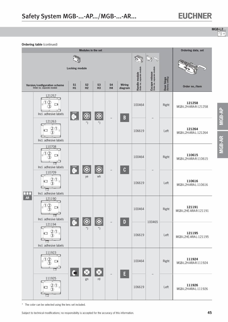
45
Safety System MGB-...-AP.../MGB-...-AR...
Subject to technical modifications; no responsibility is accepted for the accuracy of this information.
MGB-L2...
MG
B-A
RM
GB
-AP
1 23
Ordering table (continued)
Modules in the set Ordering data, set
Locking module
Han
dle
mod
ule
Ord
er n
o. s
epar
ate
mod
ule
Esca
pe r
elea
se
Ord
er n
o. s
epar
ate
mod
ule
Doo
r hi
nge
(fac
tory
set
ting)
Version/configuration schemeOrder no. separate module
S1H1
S2H2
S3H3
S4H4
Wiring diagram Order no./item
AR
121257
1 23
Incl. adhesive labels STOP
*) *)
– B
100464
–
Right 121258 MGB-L2H-ARA-R-121258
121263
32 1
Incl. adhesive labels
106619 Left 121264 MGB-L2H-ARA-L-121264
110708
321
Incl. adhesive labels STOP
ye wh
– C
100464
–
Right 110615 MGB-L2H-ARA-R-110615
110709
312
Incl. adhesive labels
106619 Left 110616 MGB-L2H-ARA-L-110616
121190
321
Incl. adhesive labels STOP
*) *)
– D
100464
100465
Right 121191 MGB-L2HE-ARA-R-121191
121194
312
Incl. adhesive labels
106619 Left 121195 MGB-L2HE-ARA-L-121195
111923
321
gn rd
– E
100464
–
Right 111924 MGB-L2H-ARA-R-111924
111925
312 106619 Left 111926
MGB-L2H-ARA-L-111926
* The color can be selected using the lens set included.
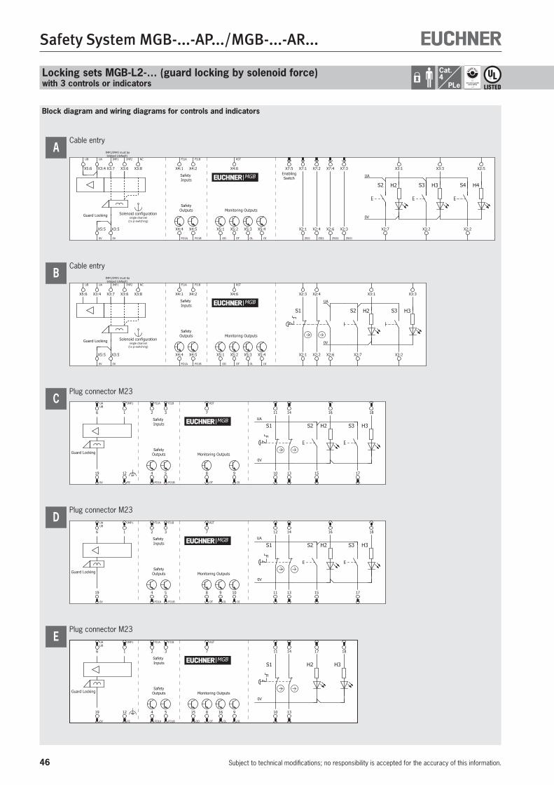
46
Safety System MGB-...-AP.../MGB-...-AR...
Subject to technical modifications; no responsibility is accepted for the accuracy of this information.
Cat.4
PLe
Block diagram and wiring diagrams for controls and indicators
Locking sets MGB-L2-… (guard locking by solenoid force)with 3 controls or indicators
Cable entry
Monitoring Outputs
Safety Inputs
H2 H3S2 S3 H4S4
UA
0V
SafetyOutputs
EnablingSwitch
IMP1/IMP2 must bebridged (default)
Guard Locking
| |
Solenoid configurationsingle channel
(1x p-switching)
FI1A
X4:1 X3:3 X2:5
OI
X5:4 X2:2X2:7 X3:2
X3:1
FI1B
X4:2
FO1A
X4:4
FO1B
X4:5
RST
X4:6
OT
X5:2
OL
X5:3
OD
X5:1
X7:5 X7:1 X7:2 X7:4 X7:3
ZSI1
X2:1
ZSI2
X2:4
ZSO2
X2:6
ZSO1
X2:3
IMP1
X3:7
IMP2
X3:6
0V
X5:5
0V
X3:5
NC
X3:8
UA
X3:4
UB
X5:6
MGB
A
Cable entry
Monitoring Outputs
Safety Inputs
H2 H3S2 S3
0V
UA
S1
SafetyOutputs
IMP1/IMP2 must bebridged (default)
Guard Locking
| |
Solenoid configurationsingle channel
(1x p-switching)
X3:3X2:3 X2:4
OI
X5:4 X2:2 X2:7 X3:2
X3:1
FI1A
X4:1
FI1B
X4:2
FO1A
X4:4
FO1B
X4:5
RST
X4:6
OT
X5:2
OL
X5:3 X2:1
OD
X5:1 X2:6
IMP1
X3:7
UA
X3:4
IMP2
X3:6
UB
X5:6
0V
X5:5
0V
X3:5
NC
X3:8
MGB
B
Plug connector M23
SafetyOutputs Monitoring OutputsGuard Locking
Safety Inputs S1 S2 S3H2 H3
UA
0V
MGB
13
UAUB
6 1811
17
16
IMP1
1
4
FO1A
5
FO1B
RST
7
8
OT
9
OI
19
0V
10
14
12
FE
15
FI1A
2
FI1B
3
C
Plug connector M23
SafetyOutputs Monitoring OutputsGuard Locking
Safety Inputs S1 S2 S3H2 H3
UA
0V
MGB
13
UAUB
6 1812
17
16
IMP1
1
4
FO1A
5
FO1B
RST
7
8
OT
10
OI
19
0V
11
14
15
FI1A
2
FI1B
3
9
OL
D
Plug connector M23
Monitoring OutputsGuard Locking
Safety Inputs S1 H2 H3
0V
SafetyOutputs
13
UAUB
6 1811 17
IMP1
1
4
FO1A
5
FO1B
RST
7
8
OT
9
OI
19
0V
10
14
12
FE
FI1A
2
FI1B
3
15
OD
16
OL
MGB
E

47
Safety System MGB-...-AP.../MGB-...-AR...
Subject to technical modifications; no responsibility is accepted for the accuracy of this information.
MGB-L2...
MG
B-A
RM
GB
-AP
1 23
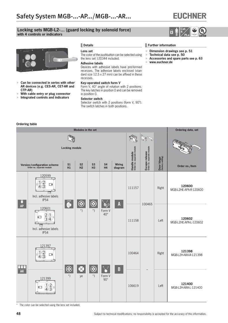
48
Safety System MGB-...-AP.../MGB-...-AR...
Subject to technical modifications; no responsibility is accepted for the accuracy of this information.
Cat.4
PLe
Locking sets MGB-L2-… (guard locking by solenoid force)with 4 controls or indicators
Ordering table
Can be connected in series with other AR devices (e.g. CES-AR, CET-AR and CTP-AR)
With cable entry or plug connector Integrated controls and indicators
Further information
Dimension drawings see p. 51 Technical data see p. 50 Accessories and spare parts see p. 63 www.euchner.de
Details
Lens setThe color of the pushbutton can be selected using the lens set 120344 included.Adhesive labelsDevices with adhesive labels have pre-formed recesses. The adhesive labels enclosed (stan-dard size 12.5 x 27 mm) can be affixed in these recesses.Key-operated switch form VForm V, 40° angle of rotation with 2 positions. The key latches in position 0 and can be removed in position 0.Selector switchSelector switch with 2 positions (form V, 90°). The switch latches in both positions.
Modules in the set Ordering data, set
Locking module
Han
dle
mod
ule
Ord
er n
o. s
epar
ate
mod
ule
Esca
pe r
elea
se
Ord
er n
o. s
epar
ate
mod
ule
Doo
r hi
nge
(fac
tory
set
ting)
Version/configuration schemeOrder no. separate module
S1H1
S2H2
S3H3
S4H4
Wiring diagram Order no./item
AP
120599
4 321
Incl. adhesive labelsIP54 STOP
*) *)
0 1
Form V 40°
A
111157
100465
Right 120600 MGB-L2HE-APA-R-120600
120601
3 412
Incl. adhesive labelsIP54
111158 Left 120602 MGB-L2HE-APA-L-120602
AR
121397
4 321
*) ye *)
0 1
Form V90°
B
100464
–
Right 121398 MGB-L2H-ARA-R-121398
121399
4 321 106619 Left 121400
MGB-L2H-ARA-L-121400
* The color can be selected using the lens set included.

49
Safety System MGB-...-AP.../MGB-...-AR...
Subject to technical modifications; no responsibility is accepted for the accuracy of this information.
MGB-L2...
MG
B-A
RM
GB
-AP
Block diagram and wiring diagrams for controls and indicators
4 321
Monitoring Outputs
12
FE
SafetyOutputs
Guard Locking
IMP1/IMP2 must bebridged (default)
Solenoid configurationsingle channel
(1x p-switching)
H2 H3S2 S3
0V
UA
S1 S4
3
1610
1315
RST
7
8
OT
9
OI
2
11 18
174
FO1A
5
FO1B
UAUB
6
NC
14
19
0V
IMP1
1
MGB
Plug connector M23A
Cable entry
Monitoring Outputs
Safety Inputs
H2 H3S3
0V
UA
S1 H1 S421
SafetyOutputs
IMP1/IMP2 must bebridged (default)
Guard Locking
| |
Solenoid configurationsingle channel
(1x p-switching)
X3:3X2:6
OI
X5:4 X2:2X3:2
X3:1
FI1A
X4:1
FI1B
X4:2
FO1A
X4:4
FO1B
X4:5
RST
X4:6
OT
X5:2
OL
X5:3 X2:1
OD
X5:1
IMP1
X3:7
UA
X3:4
IMP2
X3:6
UB
X5:6
0V
X5:5
0V
X3:5
NC
X3:8
MGB
B
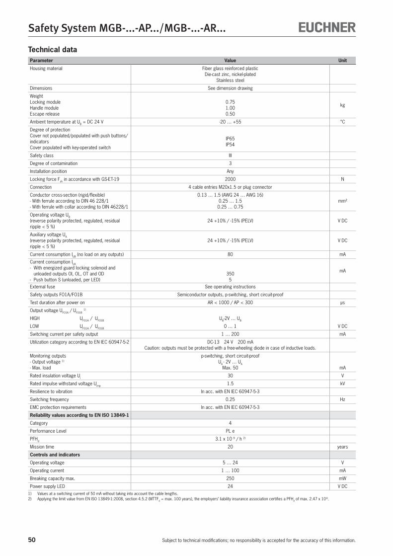
50
Safety System MGB-...-AP.../MGB-...-AR...
Subject to technical modifications; no responsibility is accepted for the accuracy of this information.
Technical dataParameter Value Unit
Housing material Fiber glass reinforced plastic Die-cast zinc, nickel-plated
Stainless steel
Dimensions See dimension drawing
WeightLocking moduleHandle moduleEscape release
0.751.000.50
kg
Ambient temperature at UB = DC 24 V -20 … +55 °C
Degree of protectionCover not populated/populated with push buttons/indicatorsCover populated with key-operated switch
IP65 IP54
Safety class III
Degree of contamination 3
Installation position Any
Locking force Fzh in accordance with GS-ET-19 2000 N
Connection 4 cable entries M20x1.5 or plug connector
Conductor cross-section (rigid/flexible)- With ferrule according to DIN 46 228/1- With ferrule with collar according to DIN 46228/1
0.13 … 1.5 (AWG 24 … AWG 16)0.25 … 1.5
0.25 … 0.75mm²
Operating voltage UB (reverse polarity protected, regulated, residual ripple < 5 %)
24 +10% / -15% (PELV) V DC
Auxiliary voltage UA (reverse polarity protected, regulated, residual ripple < 5 %)
24 +10% / -15% (PELV) V DC
Current consumption IUB (no load on any outputs) 80 mA
Current consumption IUA
- With energized guard locking solenoid and unloaded outputs OI, OL, OT and OD
- Push button S (unloaded, per LED)350
5
mA
External fuse See operating instructions
Safety outputs FO1A/FO1B Semiconductor outputs, p-switching, short circuit-proof
Test duration after power on AR < 1000 / AP < 300 μs
Output voltage UFO1A / UFO1B 1)
HIGH UFO1A / UFO1B UB-2V … UB
LOW UFO1A / UFO1B 0 … 1 V DC
Switching current per safety output 1 … 200 mA
Utilization category according to EN IEC 60947-5-2 DC-13 24 V 200 mA Caution: outputs must be protected with a free-wheeling diode in case of inductive loads.
Monitoring outputs- Output voltage 1)
- Max. load
p-switching, short circuit-proofUA - 2V … UA
Max. 50 mA
Rated insulation voltage Ui 30 V
Rated impulse withstand voltage Uimp 1.5 kV
Resilience to vibration In acc. with EN IEC 60947-5-3
Switching frequency 0.25 Hz
EMC protection requirements In acc. with EN IEC 60947-5-3
Reliability values according to EN ISO 13849-1
Category 4
Performance Level PL e
PFHd 3.1 x 10 -9 / h 2)
Mission time 20 years
Controls and indicators
Operating voltage 5 … 24 V
Operating current 1 … 100 mA
Breaking capacity max. 250 mW
Power supply LED 24 V DC1) Values at a switching current of 50 mA without taking into account the cable lengths.2) Applying the limit value from EN ISO 13849-1:2008, section 4.5.2 (MTTFd = max. 100 years), the employers’ liability insurance association certifies a PFHd of max. 2.47 x 10⁻⁸.
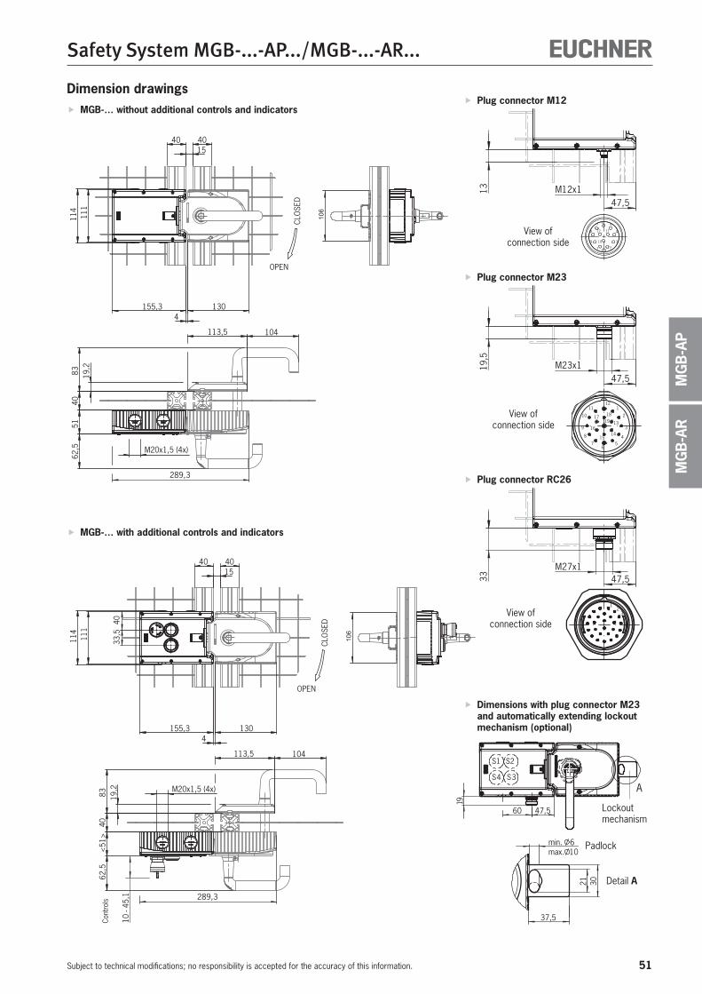
51
Safety System MGB-...-AP.../MGB-...-AR...
Subject to technical modifications; no responsibility is accepted for the accuracy of this information.
MG
B-A
RM
GB
-AP
Dimension drawings11
111
4
OPEN
CLO
SED
1540 40
113,5 104
155,3 1304
8340
<51
>62
,519
,2 M20x1,5 (4x)
289,3
10 -
45,1
4033
,5
47,560
19
min. 6
37,5
S1 S2
4S 3S
A
max. 10
3021
106
111
114
OPEN
CLO
SED
1540 40
113,5 104
155,3 1304
8340
5162
,519
,2
M20x1,5 (4x)
289,3
106
MGB-… without additional controls and indicators
MGB-… with additional controls and indicators
View of connection side
Plug connector M12
47,5
13 M12x1
12
1 2
3
4
567
8
9 10
11
Plug connector M23
47,5
19,5
M23x1
121
2
3
45
67
8
9
10
1118
13
1415
16
1719
View of connection side
Plug connector RC26
47,533
M27x1
12
3View of connection side
Cont
rols
Dimensions with plug connector M23 and automatically extending lockout mechanism (optional)
Detail A
Padlock
Lockout mechanism
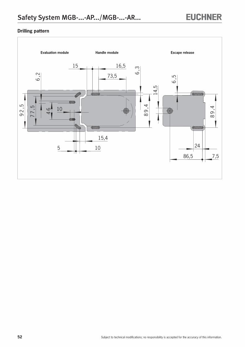
52
Safety System MGB-...-AP.../MGB-...-AR...
Subject to technical modifications; no responsibility is accepted for the accuracy of this information.
Drilling pattern
7,5
6,5
86,5
15,4
15
73,5
6,3
6,2
89
,4
245
10
46
108
9,4
77
,5
92
,5
16,5
14,5
Evaluation module Handle module Escape release
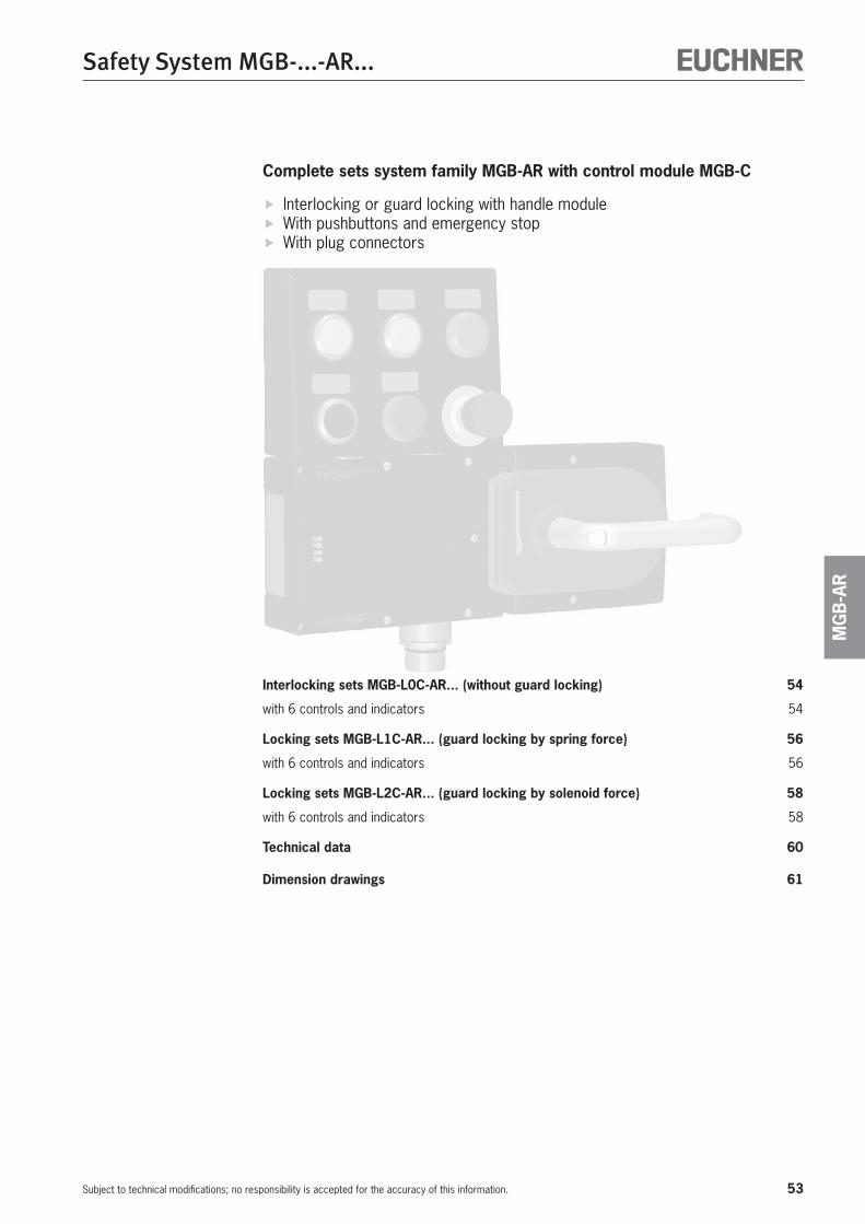
53
Safety System MGB-...-AR...
Subject to technical modifications; no responsibility is accepted for the accuracy of this information.
MG
B-A
R
Interlocking sets MGB-L0C-AR... (without guard locking) 54
with 6 controls and indicators 54
Locking sets MGB-L1C-AR... (guard locking by spring force) 56
with 6 controls and indicators 56
Locking sets MGB-L2C-AR... (guard locking by solenoid force) 58
with 6 controls and indicators 58
Technical data 60
Dimension drawings 61
Complete sets system family MGB-AR with control module MGB-C
Interlocking or guard locking with handle module With pushbuttons and emergency stop With plug connectors
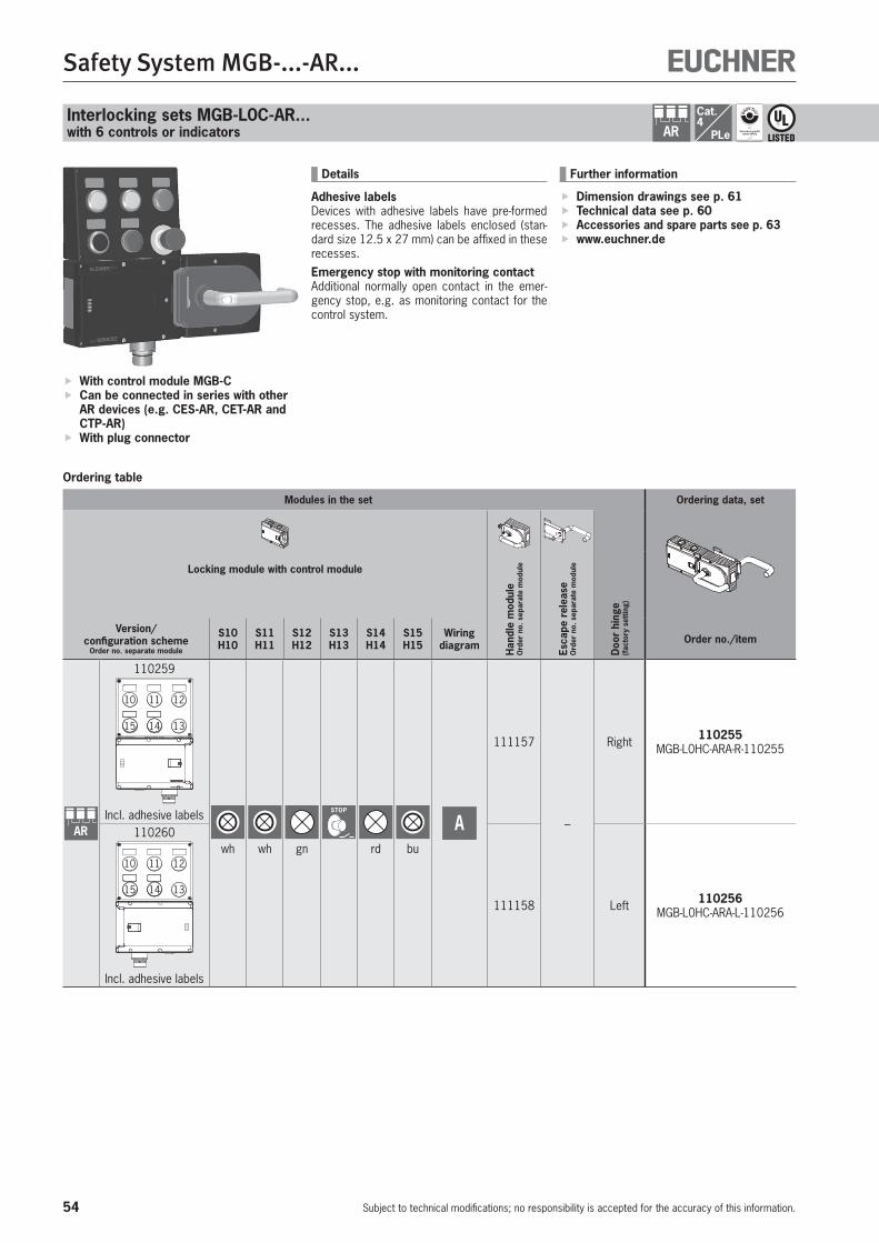
54
Safety System MGB-...-AR...
Subject to technical modifications; no responsibility is accepted for the accuracy of this information.
Cat.4
PLeAR
Ordering table
With control module MGB-C Can be connected in series with other AR devices (e.g. CES-AR, CET-AR and CTP-AR)
With plug connector
Further information
Dimension drawings see p. 61 Technical data see p. 60 Accessories and spare parts see p. 63 www.euchner.de
Interlocking sets MGB-L0C-AR... with 6 controls or indicators
Modules in the set Ordering data, set
Locking module with control module
Han
dle
mod
ule
Ord
er n
o. s
epar
ate
mod
ule
Esca
pe r
elea
se
Ord
er n
o. s
epar
ate
mod
ule
Doo
r hi
nge
(fac
tory
set
ting)
Version/ configuration scheme
Order no. separate module
S10H10
S11H11
S12H12
S13H13
S14H14
S15H15
Wiring diagram Order no./item
AR
110259
10
15
1211
14 13
Incl. adhesive labels
wh wh gn
STOP
rd bu
A
111157
–
Right 110255 MGB-L0HC-ARA-R-110255
110260
10
15
1211
14 13
Incl. adhesive labels
111158 Left 110256 MGB-L0HC-ARA-L-110256
Details
Adhesive labelsDevices with adhesive labels have pre-formed recesses. The adhesive labels enclosed (stan-dard size 12.5 x 27 mm) can be affixed in these recesses.Emergency stop with monitoring contactAdditional normally open contact in the emer-gency stop, e.g. as monitoring contact for the control system.

55
Safety System MGB-...-AR...
Subject to technical modifications; no responsibility is accepted for the accuracy of this information.
MG
B-A
R
MGB-L0C
Block diagram
SafetyOutputs Monitoring Outputs
Safety Inputs
23
22
H10 H15S10 S15
0V
UA
S13 H11S11 H12 H14
UAUB
1 20
17
18
NC
2
6
FO1A
7
FO1B
RST
16
9
OT
11
OI
3
0V
12
15
24
FI1A
4
FI1B
5
19
2114
138
OD
NC
26 25
MGB
NC
10
Plug connector RC26A

56
Safety System MGB-...-AR...
Subject to technical modifications; no responsibility is accepted for the accuracy of this information.
Cat.4
PLeARLocking sets MGB-L1C-AR... (guard locking by spring force)with 6 controls or indicators
Ordering table
With control module MGB-C Can be connected in series with other AR devices (e.g. CES-AR, CET-AR and CTP-AR)
With plug connector
Further information
Dimension drawings see p. 61 Technical data see p. 60 Accessories and spare parts see p. 63 www.euchner.de
Modules in the set Ordering data, set
Locking module with control module
Han
dle
mod
ule
Ord
er n
o. s
epar
ate
mod
ule
Esca
pe r
elea
se
Ord
er n
o. s
epar
ate
mod
ule
Doo
r hi
nge
(fac
tory
set
ting)
Version/ configuration scheme
Order no. separate module
S10H10
S11H11
S12H12
S13H13
S14H14
S15H15
Wiring diagram Order no./item
AR
109798
10
15
1211
14 13
Incl. adhesive labels
wh wh gn
STOP
rd bu
A
111157
–
Right 109806 MGB-L1HC-ARA-R-109806
109799
10
15
1211
14 13
Incl. adhesive labels
111158 Left 109807 MGB-L1HC-ARA-L-109807
Details
Adhesive labelsDevices with adhesive labels have pre-formed recesses. The adhesive labels enclosed (stan-dard size 12.5 x 27 mm) can be affixed in these recesses.Emergency stop with monitoring contactAdditional normally open contact in the emer-gency stop, e.g. as monitoring contact for the control system.

57
Safety System MGB-...-AR...
Subject to technical modifications; no responsibility is accepted for the accuracy of this information.
MG
B-A
R
MGB-L1C
Block diagram
SafetyOutputs Monitoring OutputsGuard Locking
Safety Inputs
23
22
H10 H15S10 S15
0V
UA
S13 H11S11 H12 H14
UAUB
1 20
17
18
IMP1
2
6
FO1A
7
FO1B
RST
16
9
OT
11
OI
3
0V
12
15
24
FI1A
4
FI1B
5
10
OL
19
2114
138
OD
NC
26 25
MGB
Plug connector RC26A

58
Safety System MGB-...-AR...
Subject to technical modifications; no responsibility is accepted for the accuracy of this information.
Cat.4
PLeARLocking sets MGB-L2C-AR... (guard locking by solenoid force)with 6 controls or indicators
Ordering table
With control module MGB-C Can be connected in series with other AR devices (e.g. CES-AR, CET-AR and CTP-AR)
With plug connector
Further information
Dimension drawings see p. 61 Technical data see p. 60 Accessories and spare parts see p. 63 www.euchner.de
Modules in the set Ordering data, set
Locking module with control module
Han
dle
mod
ule
Ord
er n
o. s
epar
ate
mod
ule
Esca
pe r
elea
se
Ord
er n
o. s
epar
ate
mod
ule
Doo
r hi
nge
(fac
tory
set
ting)
Version/ configuration scheme
Order no. separate module
S10H10
S11H11
S12H12
S13H13
S14H14
S15H15
Wiring diagram Order no./item
AR
112529
10
15
1211
14 13
Incl. adhesive labels
wh wh gn
STOP
rd bu
A
111157
–
Right 112531 MGB-L2HC-ARA-R-112531
112530
10
15
1211
14 13
Incl. adhesive labels
111158 Left 112532 MGB-L2HC-ARA-L-112532
Details
Adhesive labelsDevices with adhesive labels have pre-formed recesses. The adhesive labels enclosed (stan-dard size 12.5 x 27 mm) can be affixed in these recesses.Emergency stop with monitoring contactAdditional normally open contact in the emer-gency stop, e.g. as monitoring contact for the control system.
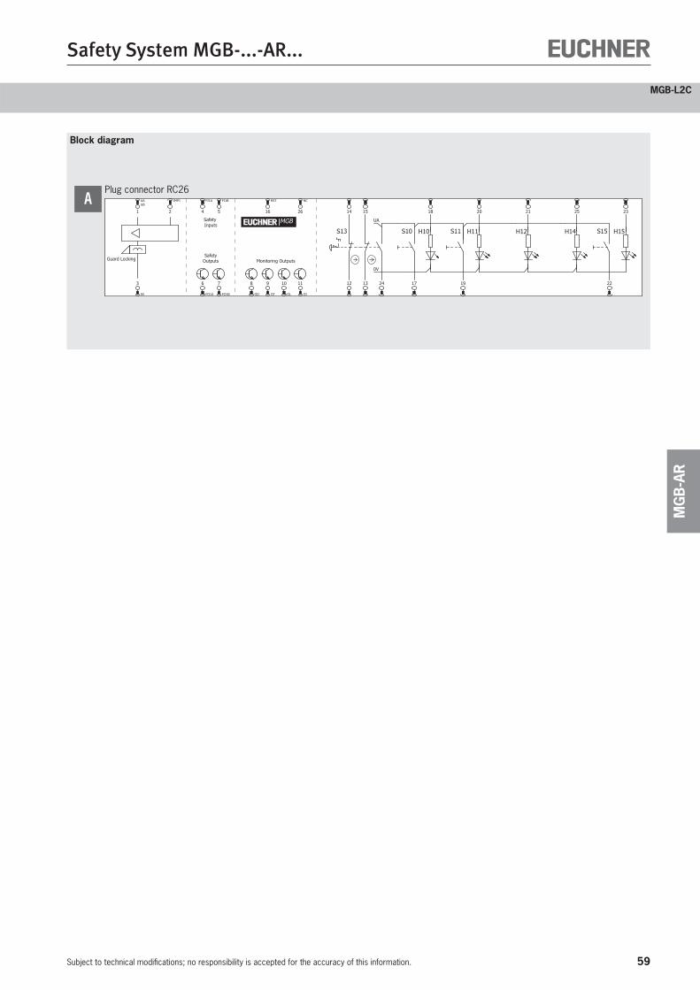
59
Safety System MGB-...-AR...
Subject to technical modifications; no responsibility is accepted for the accuracy of this information.
MG
B-A
R
MGB-L2C
Block diagram
SafetyOutputs Monitoring OutputsGuard Locking
Safety Inputs
23
22
H10 H15S10 S15
0V
UA
S13 H11S11 H12 H14
UAUB
1 20
17
18
IMP1
2
6
FO1A
7
FO1B
RST
16
9
OT
11
OI
3
0V
12
15
24
FI1A
4
FI1B
5
10
OL
19
2114
138
OD
NC
26 25
MGB
Plug connector RC26A
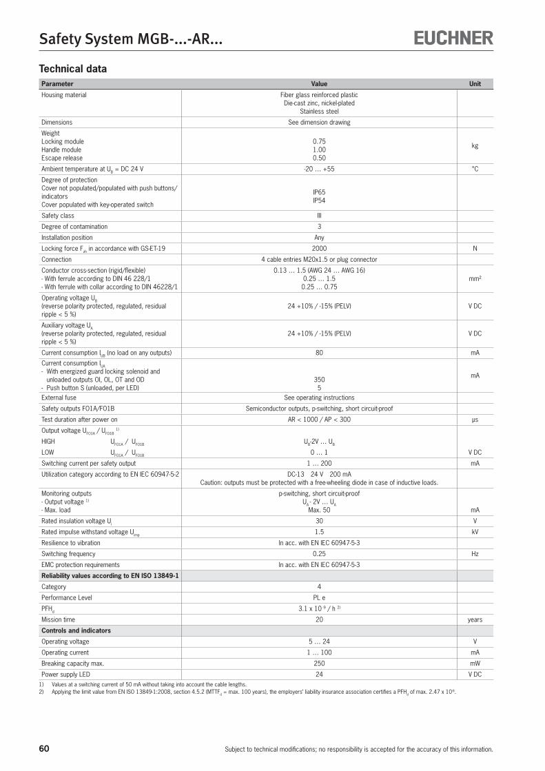
60
Safety System MGB-...-AR...
Subject to technical modifications; no responsibility is accepted for the accuracy of this information.
Technical dataParameter Value Unit
Housing material Fiber glass reinforced plastic Die-cast zinc, nickel-plated
Stainless steel
Dimensions See dimension drawing
WeightLocking moduleHandle moduleEscape release
0.751.000.50
kg
Ambient temperature at UB = DC 24 V -20 … +55 °C
Degree of protectionCover not populated/populated with push buttons/indicatorsCover populated with key-operated switch
IP65 IP54
Safety class III
Degree of contamination 3
Installation position Any
Locking force Fzh in accordance with GS-ET-19 2000 N
Connection 4 cable entries M20x1.5 or plug connector
Conductor cross-section (rigid/flexible)- With ferrule according to DIN 46 228/1- With ferrule with collar according to DIN 46228/1
0.13 … 1.5 (AWG 24 … AWG 16)0.25 … 1.5
0.25 … 0.75mm²
Operating voltage UB (reverse polarity protected, regulated, residual ripple < 5 %)
24 +10% / -15% (PELV) V DC
Auxiliary voltage UA (reverse polarity protected, regulated, residual ripple < 5 %)
24 +10% / -15% (PELV) V DC
Current consumption IUB (no load on any outputs) 80 mA
Current consumption IUA
- With energized guard locking solenoid and unloaded outputs OI, OL, OT and OD
- Push button S (unloaded, per LED)350
5
mA
External fuse See operating instructions
Safety outputs FO1A/FO1B Semiconductor outputs, p-switching, short circuit-proof
Test duration after power on AR < 1000 / AP < 300 μs
Output voltage UFO1A / UFO1B 1)
HIGH UFO1A / UFO1B UB-2V … UB
LOW UFO1A / UFO1B 0 … 1 V DC
Switching current per safety output 1 … 200 mA
Utilization category according to EN IEC 60947-5-2 DC-13 24 V 200 mA Caution: outputs must be protected with a free-wheeling diode in case of inductive loads.
Monitoring outputs- Output voltage 1)
- Max. load
p-switching, short circuit-proofUA - 2V … UA
Max. 50 mA
Rated insulation voltage Ui 30 V
Rated impulse withstand voltage Uimp 1.5 kV
Resilience to vibration In acc. with EN IEC 60947-5-3
Switching frequency 0.25 Hz
EMC protection requirements In acc. with EN IEC 60947-5-3
Reliability values according to EN ISO 13849-1
Category 4
Performance Level PL e
PFHd 3.1 x 10 -9 / h 2)
Mission time 20 years
Controls and indicators
Operating voltage 5 … 24 V
Operating current 1 … 100 mA
Breaking capacity max. 250 mW
Power supply LED 24 V DC1) Values at a switching current of 50 mA without taking into account the cable lengths.2) Applying the limit value from EN ISO 13849-1:2008, section 4.5.2 (MTTFd = max. 100 years), the employers’ liability insurance association certifies a PFHd of max. 2.47 x 10⁻⁸.
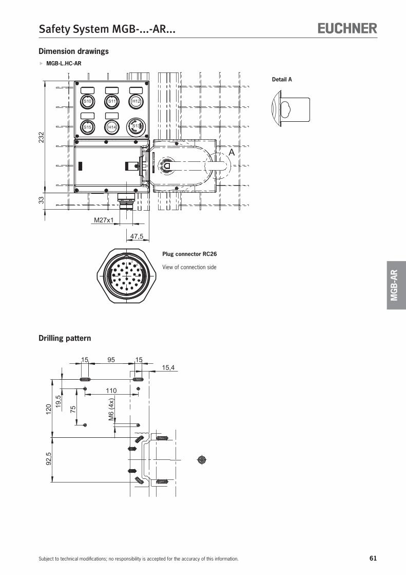
61
Safety System MGB-...-AR...
Subject to technical modifications; no responsibility is accepted for the accuracy of this information.
MG
B-A
R
Dimension drawings MGB-L.HC-AR
12
3
Plug connector RC26
View of connection side
Detail A
Drilling pattern
62
Safety System MGB-...-AR...
Subject to technical modifications; no responsibility is accepted for the accuracy of this information.
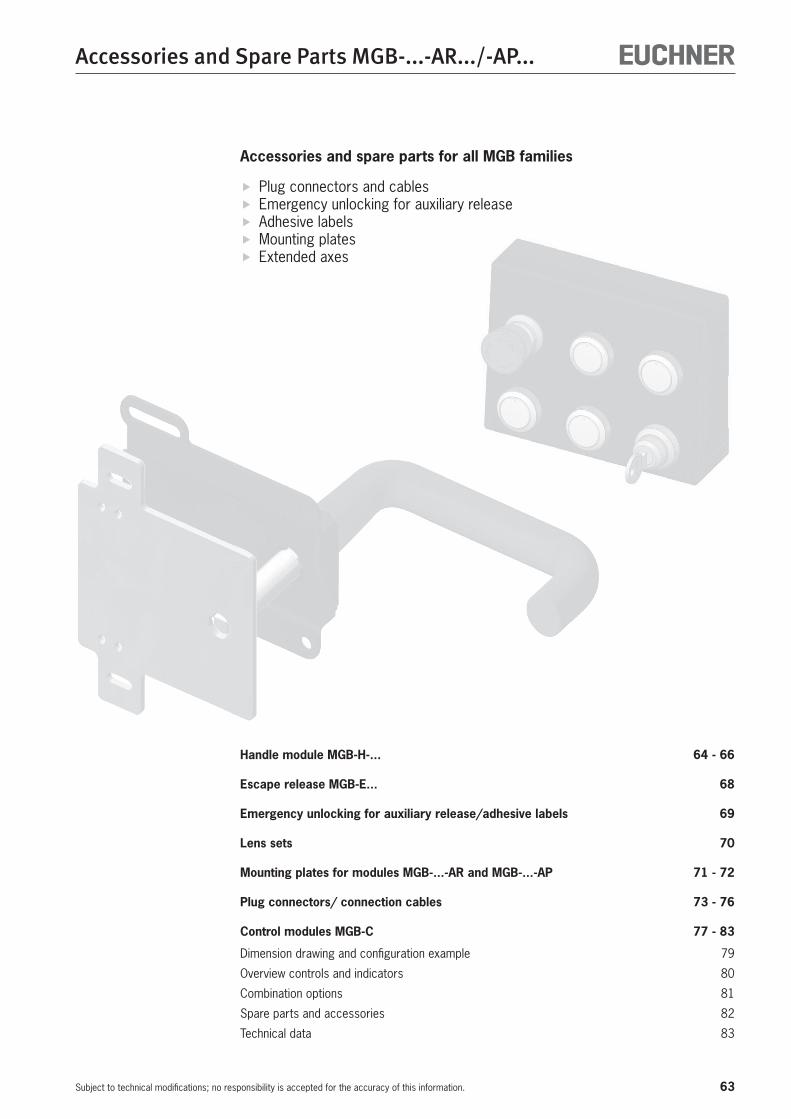
63
Accessories and Spare Parts MGB-...-AR.../-AP...
Subject to technical modifications; no responsibility is accepted for the accuracy of this information.
Accessories and spare parts for all MGB families
Plug connectors and cables Emergency unlocking for auxiliary release Adhesive labels Mounting plates Extended axes
Handle module MGB-H-... 64 - 66
Escape release MGB-E... 68
Emergency unlocking for auxiliary release/adhesive labels 69
Lens sets 70
Mounting plates for modules MGB-...-AR and MGB-...-AP 71 - 72
Plug connectors/ connection cables 73 - 76
Control modules MGB-C 77 - 83
Dimension drawing and configuration example 79
Overview controls and indicators 80
Combination options 81
Spare parts and accessories 82
Technical data 83
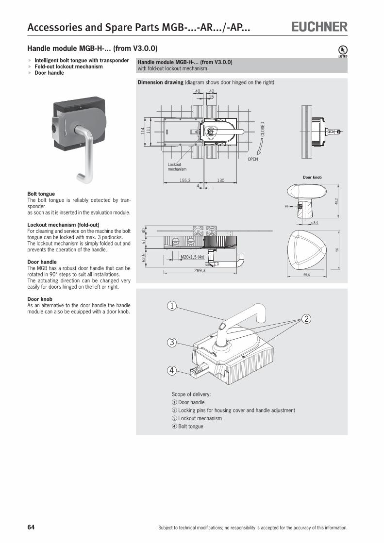
64
Accessories and Spare Parts MGB-...-AR.../-AP...
Subject to technical modifications; no responsibility is accepted for the accuracy of this information.
111
114
OPEN
CLO
SED
1540 40
155,3 1304
4051
62,5 M20x1,5 (4x)
289,3
Dimension drawing (diagram shows door hinged on the right)
Intelligent bolt tongue with transponder Fold-out lockout mechanism Door handle
Bolt tongueThe bolt tongue is reliably detected by tran-sponderas soon as it is inserted in the evaluation module.
Lockout mechanism (fold-out)For cleaning and service on the machine the bolt tongue can be locked with max. 3 padlocks.The lockout mechanism is simply folded out and prevents the operation of the handle.
Door handleThe MGB has a robust door handle that can be rotated in 90° steps to suit all installations.The actuating direction can be changed very easily for doors hinged on the left or right.
Door knobAs an alternative to the door handle the handle module can also be equipped with a door knob.
Handle module MGB-H-... (from V3.0.0)with fold-out lockout mechanism
Handle module MGB-H-... (from V3.0.0)
1
2
3
4
Scope of delivery:� Door handle� Locking pins for housing cover and handle adjustment� Lockout mechanism� Bolt tongue
Lockout mechanism
55,6
56
8,4
48,
2
M6
Door knob
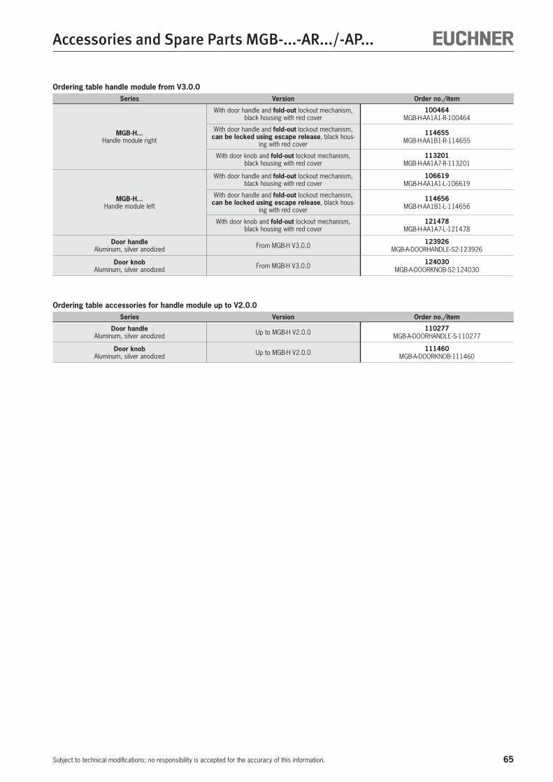
65
Accessories and Spare Parts MGB-...-AR.../-AP...
Subject to technical modifications; no responsibility is accepted for the accuracy of this information.
Ordering table handle module from V3.0.0Series Version Order no./item
MGB-H...Handle module right
With door handle and fold-out lockout mechanism, black housing with red cover
100464 MGB-H-AA1A1-R-100464
With door handle and fold-out lockout mechanism, can be locked using escape release, black hous-
ing with red cover
114655 MGB-H-AA1B1-R-114655
With door knob and fold-out lockout mechanism, black housing with red cover
113201 MGB-H-AA1A7-R-113201
MGB-H...Handle module left
With door handle and fold-out lockout mechanism, black housing with red cover
106619 MGB-H-AA1A1-L-106619
With door handle and fold-out lockout mechanism, can be locked using escape release, black hous-
ing with red cover
114656 MGB-H-AA1B1-L-114656
With door knob and fold-out lockout mechanism, black housing with red cover
121478 MGB-H-AA1A7-L-121478
Door handleAluminum, silver anodized From MGB-H V3.0.0 123926
MGB-A-DOORHANDLE-S2-123926
Door knobAluminum, silver anodized From MGB-H V3.0.0 124030
MGB-A-DOORKNOB-S2-124030
Ordering table accessories for handle module up to V2.0.0Series Version Order no./item
Door handleAluminum, silver anodized Up to MGB-H V2.0.0 110277
MGB-A-DOORHANDLE-S-110277
Door knobAluminum, silver anodized Up to MGB-H V2.0.0 111460
MGB-A-DOORKNOB-111460
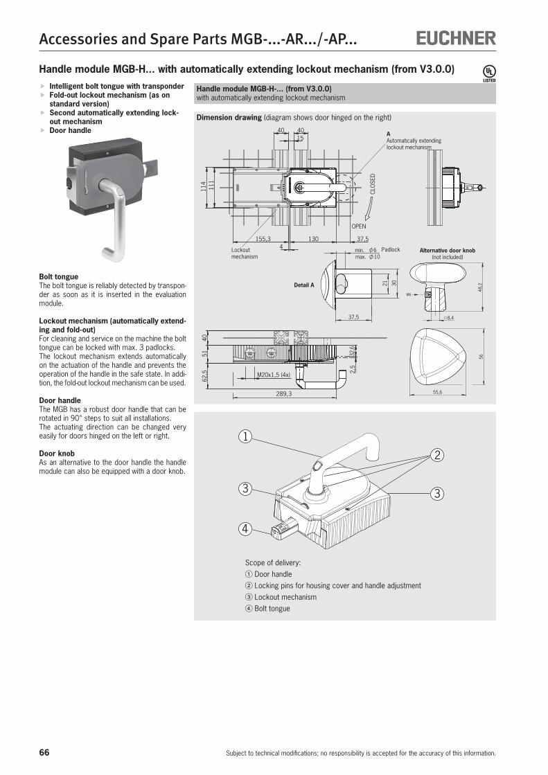
66
Accessories and Spare Parts MGB-...-AR.../-AP...
Subject to technical modifications; no responsibility is accepted for the accuracy of this information.
111
114
OPEN
CLO
SED
1540 40
155,3 130 37,54
4051
62,5 M20x1,5 (4x)
289,3
32,6
2,5
min. 6
37,5
max. 10
3021
Dimension drawing (diagram shows door hinged on the right)
Intelligent bolt tongue with transponder Fold-out lockout mechanism (as on standard version)
Second automatically extending lock-out mechanism
Door handle
Bolt tongueThe bolt tongue is reliably detected by transpon-der as soon as it is inserted in the evaluation module.
Lockout mechanism (automatically extend-ing and fold-out)For cleaning and service on the machine the bolt tongue can be locked with max. 3 padlocks.The lockout mechanism extends automatically on the actuation of the handle and prevents the operation of the handle in the safe state. In addi-tion, the fold-out lockout mechanism can be used.
Door handleThe MGB has a robust door handle that can be rotated in 90° steps to suit all installations.The actuating direction can be changed very easily for doors hinged on the left or right.
Door knobAs an alternative to the door handle the handle module can also be equipped with a door knob.
Handle module MGB-H-... (from V3.0.0)with automatically extending lockout mechanism
Handle module MGB-H... with automatically extending lockout mechanism (from V3.0.0)
1
2
3
4
3
Scope of delivery:� Door handle� Locking pins for housing cover and handle adjustment� Lockout mechanism� Bolt tongue
Lockout mechanism
AAutomatically extending lockout mechanism
55,6
56
8,4
48,
2
M6
Alternative door knob(not included)
Detail A
Padlock

67
Accessories and Spare Parts MGB-...-AR.../-AP...
Subject to technical modifications; no responsibility is accepted for the accuracy of this information.
Series Version Order no./item
MGB-H...Handle module right
With fold-out and also second automatically ex-tending lockout mechanism, black housing with red
cover
111157 MGB-H-AA1A3-R-111157
With door handle and fold-out lockout mechanism, can be locked using escape release, black hous-
ing with red cover
116813 MGB-H-AA1B2-R-116813
MGB-H...Handle module left
With fold-out and also second automatically ex-tending lockout mechanism, black housing with red
cover
111158 MGB-H-AA1A3-L-111158
With door handle and fold-out lockout mechanism, can be locked using escape release, black hous-
ing with red cover
116814 MGB-H-AA1B2-L-116814
Door handleAluminum, silver anodized From MGB-H V3.0.0 123926
MGB-A-DOORHANDLE-S2-123926
Door knobAluminum, silver anodized From MGB-H V3.0.0 124030
MGB-A-DOORKNOB-S2-124030
Ordering table
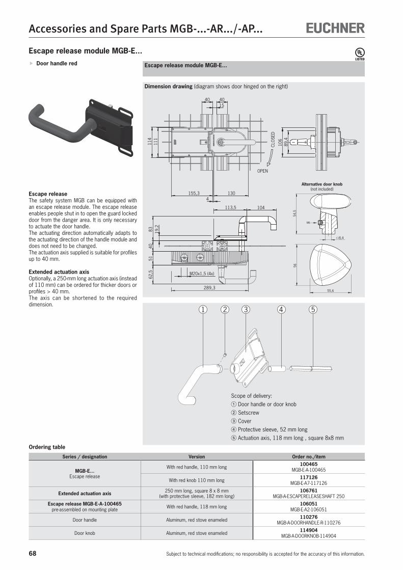
68
Accessories and Spare Parts MGB-...-AR.../-AP...
Subject to technical modifications; no responsibility is accepted for the accuracy of this information.
111
114
OPEN
CLO
SED
1540 40
89,4
113,5 104
155,3 1304
8340
5162
,519
,2
M20x1,5 (4x)
289,3
106
Dimension drawing (diagram shows door hinged on the right)
Door handle red
Escape releaseThe safety system MGB can be equipped with an escape release module. The escape release enables people shut in to open the guard locked door from the danger area. It is only necessary to actuate the door handle.The actuating direction automatically adapts to the actuating direction of the handle module and does not need to be changed.The actuation axis supplied is suitable for profiles up to 40 mm.
Extended actuation axisOptionally, a 250-mm long actuation axis (instead of 110 mm) can be ordered for thicker doors or profiles > 40 mm.The axis can be shortened to the required dimension.
Escape release module MGB-E...
Escape release module MGB-E...
1 2 3 4 5
Scope of delivery:� Door handle or door knob� Setscrew� Cover� Protective sleeve, 52 mm long� Actuation axis, 118 mm long , square 8x8 mm
Series / designation Version Order no./item
MGB-E...Escape release
With red handle, 110 mm long 100465 MGB-E-A-100465
With red knob 110 mm long 117126 MGB-E-A7-117126
Extended actuation axis 250 mm long, square 8 x 8 mm(with protective sleeve, 182 mm long)
106761 MGB-A-ESCAPERELEASESHAFT 250
Escape release MGB-E-A-100465 pre-assembled on mounting plate With red handle, 118 mm long 106051
MGB-E-A2-106051
Door handle Aluminum, red stove enameled 110276 MGB-A-DOORHANDLE-R-110276
Door knob Aluminum, red stove enameled 114904 MGB-A-DOORKNOB-114904
Ordering table
5655,6
54,5
8,4
M6
Alternative door knob(not included)
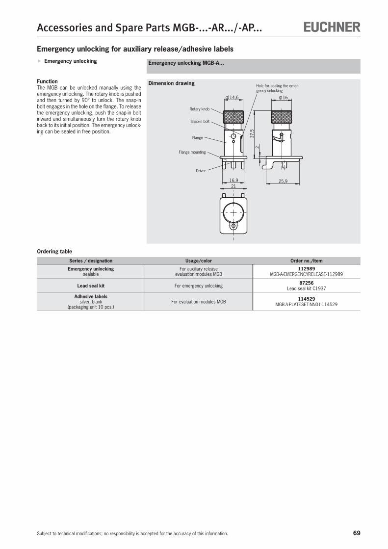
69
Accessories and Spare Parts MGB-...-AR.../-AP...
Subject to technical modifications; no responsibility is accepted for the accuracy of this information.
Emergency unlocking
Emergency unlocking for auxiliary release/adhesive labels
Dimension drawing
Emergency unlocking MGB-A...
FunctionThe MGB can be unlocked manually using the emergency unlocking. The rotary knob is pushed and then turned by 90° to unlock. The snap-in bolt engages in the hole on the flange. To release the emergency unlocking, push the snap-in bolt inward and simultaneously turn the rotary knob back to its initial position. The emergency unlock-ing can be sealed in free position.
16
37,5
2
25,916,9
14,6
21
Hole for sealing the emer-gency unlocking
Rotary knob
Snap-in bolt
Flange
Flange mounting
Driver
Series / designation Usage/color Order no./item
Emergency unlockingsealable
For auxiliary release evaluation modules MGB
112989 MGB-A-EMERGENCYRELEASE-112989
Lead seal kit For emergency unlocking 87256 Lead seal kit C1937
Adhesive labelssilver, blank
(packaging unit 10 pcs.)For evaluation modules MGB 114529
MGB-A-PLATESET-NN01-114529
Ordering table

70
Accessories and Spare Parts MGB-...-AR.../-AP...
Subject to technical modifications; no responsibility is accepted for the accuracy of this information.
Series / designation Usage/color Order no./item
Lens set3 pcs.
1 x GN 1 x YE 126158 MGB-A-LENSSET-SY03-1261581 x WH
Lens sets6 pcs.
2 x WH / 1 x BU / 1 x YE / 1 x GN / 1 x RD 120344 MGB-A-LENSSET-0001-120344
1 x WH / 1 x BU / 1 x YE / 1 x GN / 1 x RD / 1 x BK 120378 MGB-A-LENSSET-0002-120378
1 x WH 1 x WH
120377 MGB-A-LENSSET-SY01-1203771 x GN 1 x WH
1 x WH 1 x WH
Lens set15 pcs.
1 x WH 4 x BK
125359 MGB-A-LENSSET-SY02-125359
1 x WH 1 x WH
2 x WH 2 x WH
1 x WH OK 1 x WH
1 x WH 1 x WH
Ordering table
Lens sets
Lens set

71
Accessories and Spare Parts MGB-...-AR.../-AP...
Subject to technical modifications; no responsibility is accepted for the accuracy of this information.
Easy and quick mounting (only two screws required)
Quick module replacement Robust stainless steel plate Suitable for doors hinged on the right or left
Mounting plate for evaluation moduleSuitable for all interlocking or locking modules in the system families AR and AP. Two screws are sufficient for fastening the mounting plates. Important: Only use if the handle module is also fastened to a mounting plate.
Mounting plate for evaluation module
Mounting plates for modules MGB-...-AR... and MGB-...-AP...
Series / designation Version Order no./item
Mounting plate for evaluation module Suitable for all MGB-L.-AR.-... and MGB-L.-AP.-... 109490 MGB-A-MOUNTINGPLATE-L-109490
Mounting plate for handle module Suitable for all MGB handle modules 109491 MGB-A-MOUNTINGPLATE-H-109491
Mounting plate for escape release Suitable for all MGB escape releases 109492 MGB-A-MOUNTINGPLATE-E-109492
Mounting plate for evaluation module-control module combination
Suitable for all MGB-L.-AR.-... and MGB-L.-AP.-... in combination with a control module MGB-C...
110072 MGB-A-MOUNTINGPLATE-LC-110072
Ordering table
4
86,0
5
46
35
10
35
15
3011
0
6,5
170
20,54
17,5
135
17,5
155
M6
(4x)
4
10
89,4 11
0
12
30
17,5
(4x)
12,5
170
17,5
135
1 7,5
32
130,5
15 25
6,5
M6 16
Mounting plate for handle modules
Mounting plate for handle moduleSuitable for all MGB handle modules. Two screws are sufficient for fastening the mounting plates. Important: Only use if the evaluation module is also fastened to a mounting plate.
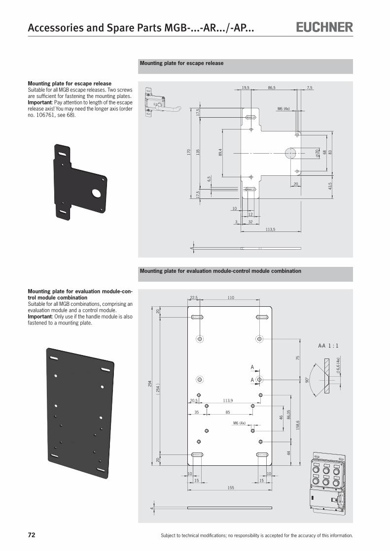
72
Accessories and Spare Parts MGB-...-AR.../-AP...
Subject to technical modifications; no responsibility is accepted for the accuracy of this information.
20
10
1289
,4
86,5
6,5
(4x)
170
7,5
32
135
43,5
83
17,5
68
17,5
3
113,5
20
M6
19,5
4
4
A-A 1 : 1
6,6
(4x)
90°
158,
675
20,5
155
22,5
113,9
85
86,0
5
254
35
46
10
15
44
15
294
(4x)
2020
M6
10
110
A
A
Mounting plate for escape release
Mounting plate for evaluation module-control module combination
Mounting plate for escape releaseSuitable for all MGB escape releases. Two screws are sufficient for fastening the mounting plates. Important: Pay attention to length of the escape release axis! You may need the longer axis (order no. 106761, see 68).
Mounting plate for evaluation module-con-trol module combinationSuitable for all MGB combinations, comprising an evaluation module and a control module. Important: Only use if the handle module is also fastened to a mounting plate.
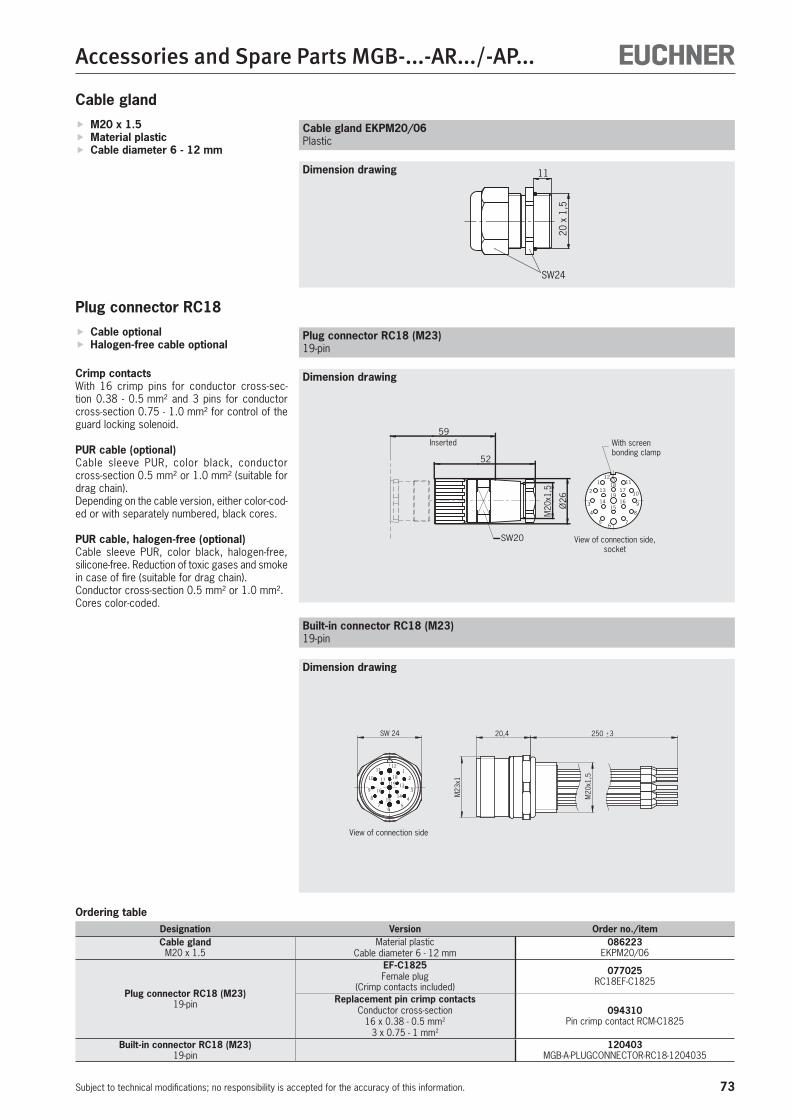
73
Accessories and Spare Parts MGB-...-AR.../-AP...
Subject to technical modifications; no responsibility is accepted for the accuracy of this information.
Cable optional Halogen-free cable optional
Crimp contactsWith 16 crimp pins for conductor cross-sec-tion 0.38 - 0.5 mm² and 3 pins for conductor cross-section 0.75 - 1.0 mm² for control of the guard locking solenoid.
PUR cable (optional)Cable sleeve PUR, color black, conductor cross-section 0.5 mm² or 1.0 mm² (suitable for drag chain).Depending on the cable version, either color-cod-ed or with separately numbered, black cores.
PUR cable, halogen-free (optional)Cable sleeve PUR, color black, halogen-free, silicone-free. Reduction of toxic gases and smoke in case of fire (suitable for drag chain). Conductor cross-section 0.5 mm² or 1.0 mm².Cores color-coded.
Plug connector RC18
18
19
15
1211
9
5
4
3
2
1
17
1614
13
6
10
8
7
SW20M
20x1
,5
52
59
Ø26
Plug connector RC18 (M23)19-pin
Inserted With screen bonding clamp
View of connection side, socket
Dimension drawing
Ordering tableDesignation Version Order no./itemCable gland
M20 x 1.5Material plastic
Cable diameter 6 - 12 mm086223
EKPM20/06
Plug connector RC18 (M23)19-pin
EF-C1825Female plug
(Crimp contacts included)
077025 RC18EF-C1825
Replacement pin crimp contactsConductor cross-section
16 x 0.38 - 0.5 mm2
3 x 0.75 - 1 mm2
094310 Pin crimp contact RCM-C1825
Built-in connector RC18 (M23)19-pin
120403 MGB-A-PLUGCONNECTOR-RC18-1204035
M23
x1
M20
x1,5
20,4 250 3 SW 24
7
8
9 16
15
65
144
3
2
13
1
1918
1211
10 17
Built-in connector RC18 (M23)19-pin
Dimension drawing
View of connection side
M20 x 1.5 Material plastic Cable diameter 6 - 12 mm
Cable gland
SW24
11
20 x
1,5
Cable gland EKPM20/06Plastic
Dimension drawing
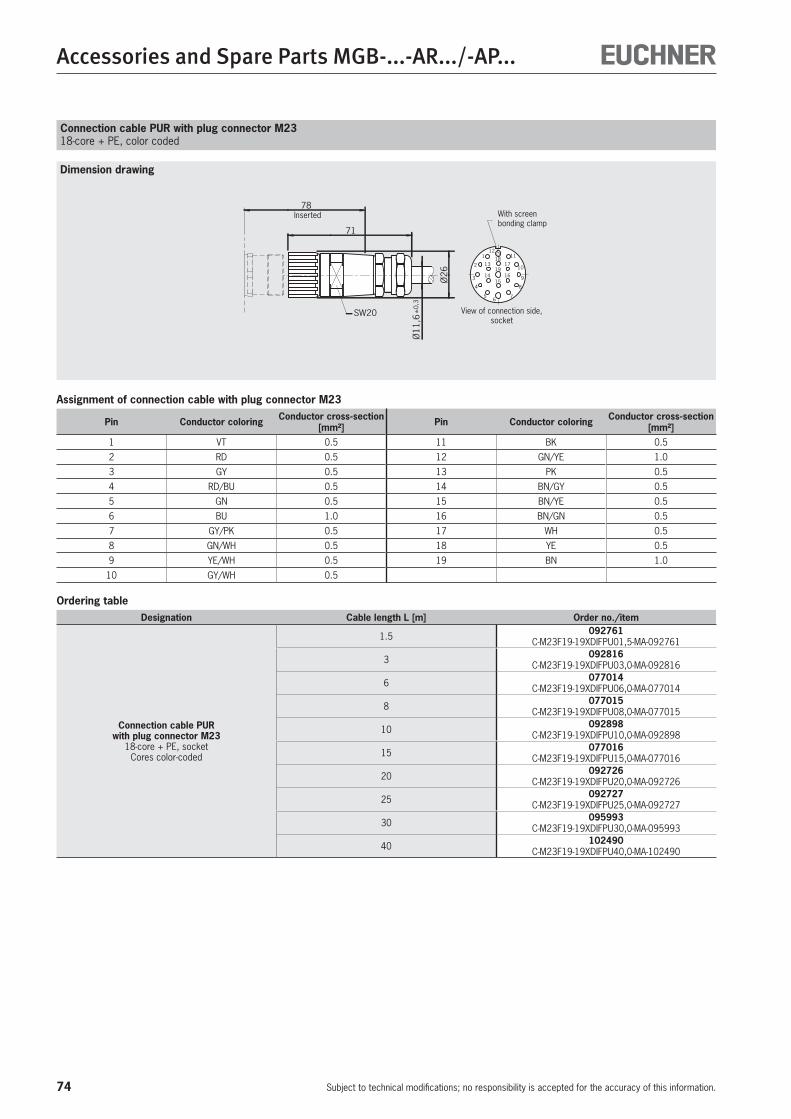
74
Accessories and Spare Parts MGB-...-AR.../-AP...
Subject to technical modifications; no responsibility is accepted for the accuracy of this information.
Ordering tableDesignation Cable length L [m] Order no./item
Connection cable PUR with plug connector M23
18-core + PE, socketCores color-coded
1.5 092761 C-M23F19-19XDIFPU01,5-MA-092761
3 092816 C-M23F19-19XDIFPU03,0-MA-092816
6 077014 C-M23F19-19XDIFPU06,0-MA-077014
8 077015 C-M23F19-19XDIFPU08,0-MA-077015
10 092898 C-M23F19-19XDIFPU10,0-MA-092898
15 077016 C-M23F19-19XDIFPU15,0-MA-077016
20 092726 C-M23F19-19XDIFPU20,0-MA-092726
25 092727 C-M23F19-19XDIFPU25,0-MA-092727
30 095993 C-M23F19-19XDIFPU30,0-MA-095993
40 102490 C-M23F19-19XDIFPU40,0-MA-102490
18
19
15
1211
9
5
4
3
2
1
17
1614
13
6
10
8
7
SW20
Ø26
71
78
Ø11
,6±
0,3
Connection cable PUR with plug connector M2318-core + PE, color coded
Inserted With screen bonding clamp
View of connection side, socket
Assignment of connection cable with plug connector M23
Pin Conductor coloring Conductor cross-section [mm²] Pin Conductor coloring Conductor cross-section
[mm²]1 VT 0.5 11 BK 0.5
2 RD 0.5 12 GN/YE 1.0
3 GY 0.5 13 PK 0.5
4 RD/BU 0.5 14 BN/GY 0.5
5 GN 0.5 15 BN/YE 0.5
6 BU 1.0 16 BN/GN 0.5
7 GY/PK 0.5 17 WH 0.5
8 GN/WH 0.5 18 YE 0.5
9 YE/WH 0.5 19 BN 1.0
10 GY/WH 0.5
Dimension drawing
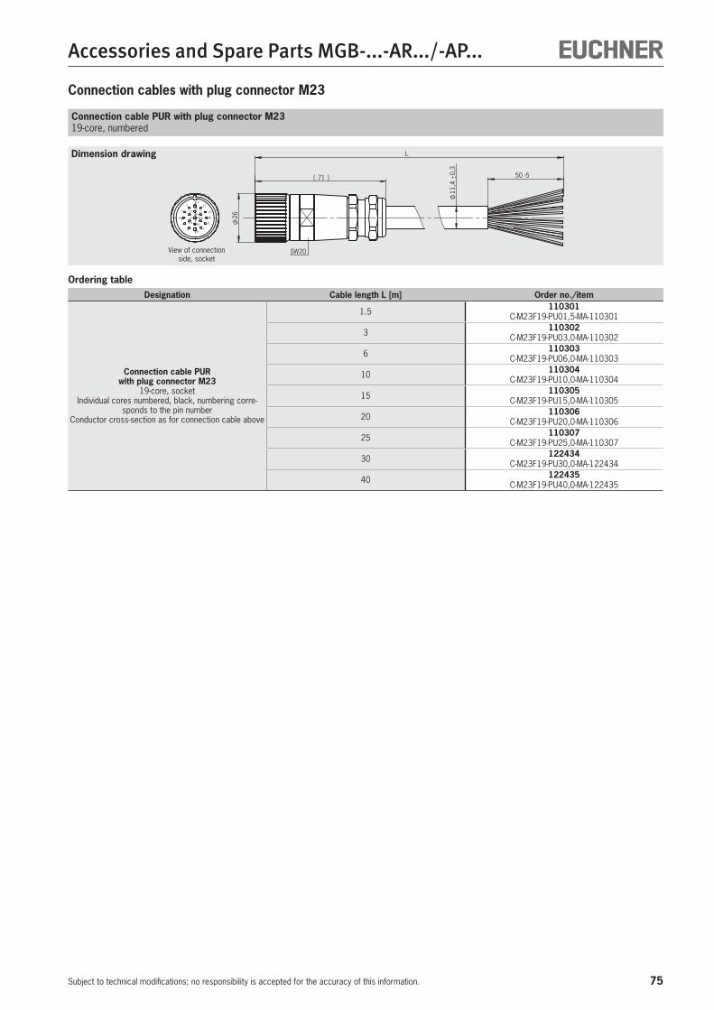
75
Accessories and Spare Parts MGB-...-AR.../-AP...
Subject to technical modifications; no responsibility is accepted for the accuracy of this information.
Connection cables with plug connector M23
Ordering tableDesignation Cable length L [m] Order no./item
Connection cable PUR with plug connector M23
19-core, socketIndividual cores numbered, black, numbering corre-
sponds to the pin numberConductor cross-section as for connection cable above
1.5 110301 C-M23F19-PU01,5-MA-110301
3 110302 C-M23F19-PU03,0-MA-110302
6 110303 C-M23F19-PU06,0-MA-110303
10 110304 C-M23F19-PU10,0-MA-110304
15 110305 C-M23F19-PU15,0-MA-110305
20 110306 C-M23F19-PU20,0-MA-110306
25 110307 C-M23F19-PU25,0-MA-110307
30 122434 C-M23F19-PU30,0-MA-122434
40 122435 C-M23F19-PU40,0-MA-122435
Connection cable PUR with plug connector M2319-core, numbered
Dimension drawing
View of connection side, socket
71
26
L
SW20
11,4
0,
3
50 -5
12
4
2
5
1
3
67
8
9
10
1118
13
14 15
16
1719
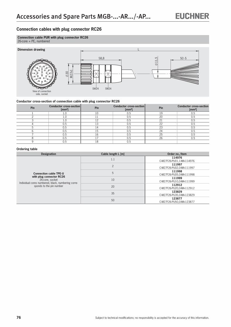
76
Accessories and Spare Parts MGB-...-AR.../-AP...
Subject to technical modifications; no responsibility is accepted for the accuracy of this information.
Connection cables with plug connector RC26
Connection cable PUR with plug connector RC2626-core + PE, numbered
Conductor cross-section of connection cable with plug connector RC26
Pin Conductor cross-section [mm²] Pin Conductor cross-section
[mm²] Pin Conductor cross-section [mm²]
1 1.0 10 0.5 19 0.52 1.0 11 0.5 20 0.53 1.0 12 0.5 21 0.54 0.5 13 0.5 22 0.55 0.5 14 0.5 23 0.56 0.5 15 0.5 24 0.57 0.5 16 0.5 25 0.58 0.5 17 0.5 26 0.59 0.5 18 0.5
Dimension drawing
Ordering tableDesignation Cable length L [m] Order no./item
Connection cable TPE-U with plug connector RC26
26-core, socketIndividual cores numbered, black, numbering corre-
sponds to the pin number
1.1 114976 C-M27F26-PU01,1-MA-114976
2 111997 C-M27F26-PU02,0-MA-111997
5 111998 C-M27F26-PU05,0-MA-111998
10 111999 C-M27F26-PU10,0-MA-111999
20 112912 C-M27F26-PU20,0-MA-112912
35 123829 C-M27F26-PU35,0-MA-123829
50 123877 C-M27F26-PU50,0-MA-123877
58,8
30
L
M27
x1
SW24 SW24
11,5 50 -5
26
2524
23
22
2120
19
18
1716
1514
13
12
11
109
87
6
5
4
32
1
View of connection side, socket
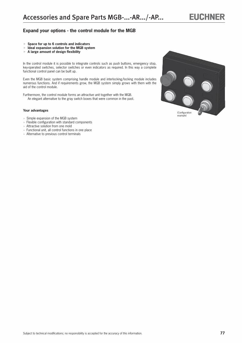
77
Accessories and Spare Parts MGB-...-AR.../-AP...
Subject to technical modifications; no responsibility is accepted for the accuracy of this information.
Expand your options - the control module for the MGB
Space for up to 6 controls and indicators Ideal expansion solution for the MGB system A large amount of design flexibility
In the control module it is possible to integrate controls such as push buttons, emergency stop, key-operated switches, selector switches or even indicators as required. In this way a complete functional control panel can be built up.
Even the MGB basic system comprising handle module and interlocking/locking module includes numerous functions. And if requirements grow, the MGB system simply grows with them with the aid of the control module.
Furthermore, the control module forms an attractive unit together with the MGB. An elegant alternative to the gray switch boxes that were common in the past.
Your advantages
Simple expansion of the MGB system Flexible configuration with standard components Attractive solution from one mold Functional unit, all control functions in one place Alternative to previous control terminals
(Configuration example)
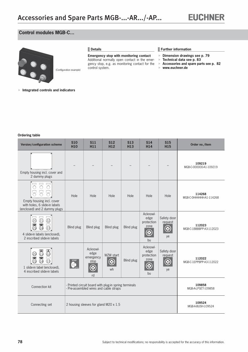
78
Accessories and Spare Parts MGB-...-AR.../-AP...
Subject to technical modifications; no responsibility is accepted for the accuracy of this information.
Control modules MGB-C...
Ordering table
Integrated controls and indicators
Version/configuration scheme S10H10
S11H11
S12H12
S13H13
S14H14
S15H15
Order no./item
Empty housing incl. cover and 2 dummy plugs
– – – – – – 109219 MGB-C-000000-A1-109219
Empty housing incl. cover with holes, 6 slide-in labels
(enclosed) and 2 dummy plugs
Hole Hole Hole Hole Hole Hole 114268 MGB-C-0HHHHHH-A1-114268
10
15
1211
14 13
4 slide-in labels (enclosed), 2 inscribed slide-in labels
Blind plug Blind plug Blind plug Blind plug
Acknowl-edge
protection zone
bu
Safety door request
ye
112023 MGB-C-1BBBBPP-A3-112023
15
1211
14 13
10
1 slide-in label (enclosed), 4 inscribed slide-in labels
STOP
Acknowl-edge
emergency stop
rd
WZW start
wh
Blind plug
Acknowl-edge
protection zone
bu
Safety door request
ye
112022 MGB-C-1EPPBPP-A3-112022
Connection kit - Printed circuit board with plug-in spring terminals- Pre-assembled wires and cable straps
109858 MGB-A-LPSET-109858
Connecting set 2 housing sleeves for gland M20 x 1.5 109524 MGB-A-BUSH-109524
Further information
Dimension drawings see p. 79 Technical data see p. 83 Accessories and spare parts see p. 82 www.euchner.de
Details
Emergency stop with monitoring contactAdditional normally open contact in the emer-gency stop, e.g. as monitoring contact for the control system.
(Configuration example)
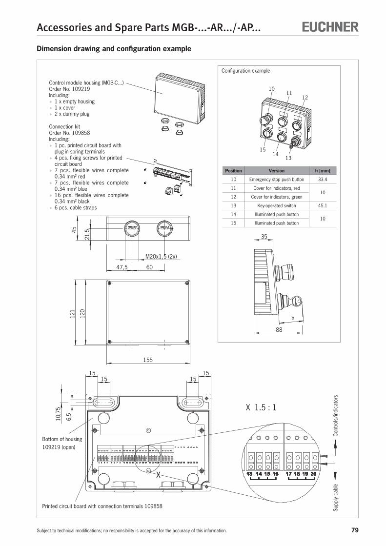
79
Accessories and Spare Parts MGB-...-AR.../-AP...
Subject to technical modifications; no responsibility is accepted for the accuracy of this information.
15
021,5
2,
88
4
35
h
155
21
X
1515
1515
10,7
5
6
M20x1,5 (2x)
15
47,5 60
X 1.5 : 1
1011
12
1514
13
Dimension drawing and configuration example
Control module housing (MGB-C...)Order No. 109219Including:
1 x empty housing 1 x cover 2 x dummy plug
Connection kit Order No. 109858Including:
1 pc. printed circuit board with plug-in spring terminals
4 pcs. fixing screws for printed circuit board
7 pcs. flexible wires complete 0.34 mm² red
7 pcs. flexible wires complete 0.34 mm² blue
16 pcs. flexible wires complete 0.34 mm² black
6 pcs. cable straps
Bottom of housing109219 (open)
Printed circuit board with connection terminals 109858
Supp
ly c
able
Cont
rols
/ind
icat
ors
Configuration example
Position Version h [mm]
10 Emergency stop push button 33.4
11 Cover for indicators, red10
12 Cover for indicators, green
13 Key-operated switch 45.1
14 Illuminated push button10
15 Illuminated push button
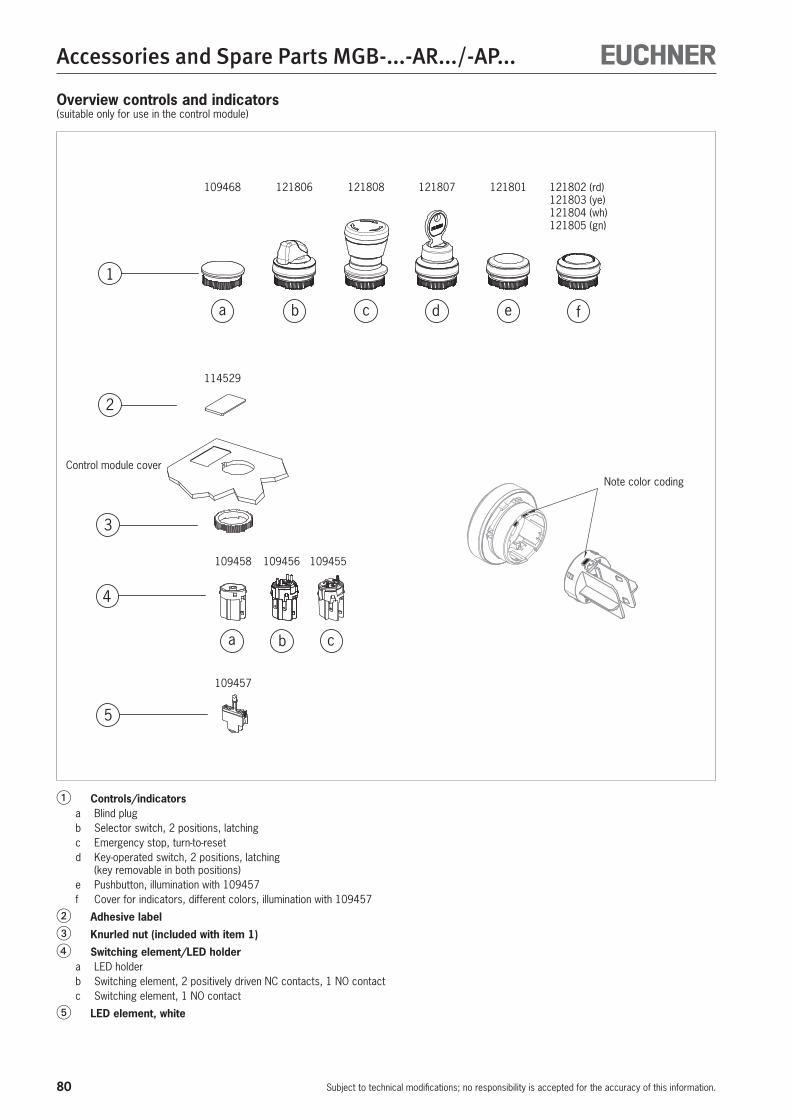
80
Accessories and Spare Parts MGB-...-AR.../-AP...
Subject to technical modifications; no responsibility is accepted for the accuracy of this information.
Overview controls and indicators(suitable only for use in the control module)
1
a b c
a b c
d e f
2
3
4
5
114529
109455109456109458
109457
109468 121806 121808 121807 121802 (rd)121803 (ye)121804 (wh)121805 (gn)
121801
� Controls/indicatorsa Blind plugb Selector switch, 2 positions, latchingc Emergency stop, turn-to-resetd Key-operated switch, 2 positions, latching
(key removable in both positions)e Pushbutton, illumination with 109457f Cover for indicators, different colors, illumination with 109457
� Adhesive label� Knurled nut (included with item 1)� Switching element/LED holder
a LED holderb Switching element, 2 positively driven NC contacts, 1 NO contact c Switching element, 1 NO contact
� LED element, white
Control module coverNote color coding
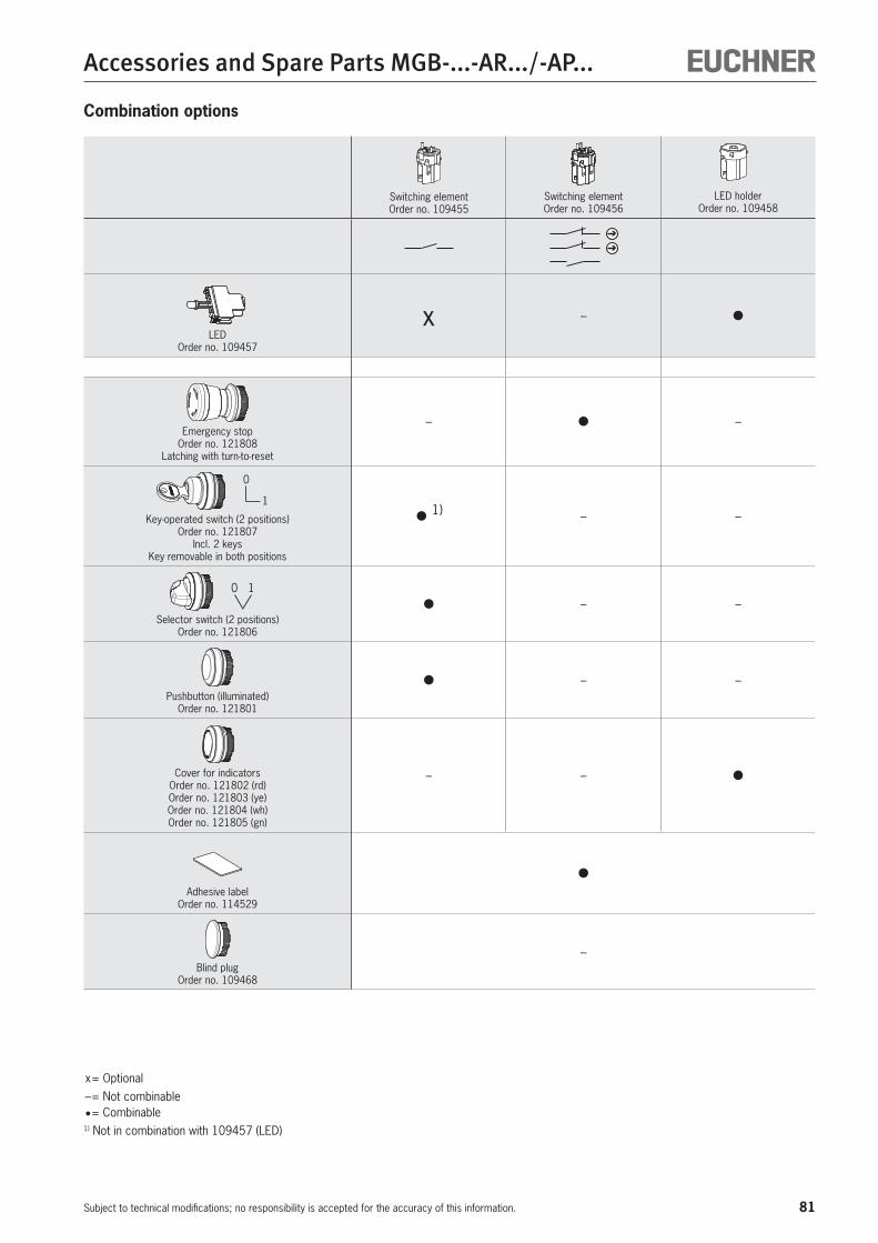
81
Accessories and Spare Parts MGB-...-AR.../-AP...
Subject to technical modifications; no responsibility is accepted for the accuracy of this information.
Switching element Order no. 109455
Switching element Order no. 109456
LED holder Order no. 109458
LED Order no. 109457
x – •
Emergency stop Order no. 121808
Latching with turn-to-reset
– • –
1
0
Key-operated switch (2 positions) Order no. 121807
Incl. 2 keys Key removable in both positions
• 1) – –
10
Selector switch (2 positions) Order no. 121806
• – –
Pushbutton (illuminated) Order no. 121801
• – –
Cover for indicators Order no. 121802 (rd)Order no. 121803 (ye)Order no. 121804 (wh)Order no. 121805 (gn)
– – •
Adhesive label Order no. 114529
•
Blind plug Order no. 109468
–
x = Optional – = Not combinable • = Combinable1) Not in combination with 109457 (LED)
Combination options
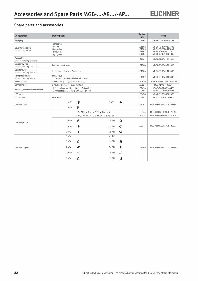
82
Accessories and Spare Parts MGB-...-AR.../-AP...
Subject to technical modifications; no responsibility is accepted for the accuracy of this information.
Spare parts and accessories
Designation Description Order no. Item
Blind plug 109468 MP-A-B-00-00-00-109468
Cover for indicators (without LED holder)
Transparent - (rd) red - (ye) yellow - (wh) white - (gn) green
121802 121803 121804 121805
MP-B-L-R0-RD-00-121802 MP-B-L-R0-YE-00-121803 MP-B-L-R0-WH-00-121804 MP-B-L-R0-GN-00-121805
Pushbutton (without switching element)
121801 MP-B-P-RT-NC-A1-121801
Emergency stop (without switching element)
Latching, turn-to-reset 121808 MP-B-E-RD-00-A4-121808
Selector switch (without switching element)
2 positions, latching in 2 positions 121806 MP-B-S-RR-00-A2-121806
Key-operated switch (without switching element)
Incl. 2 keys 2 positions; key removable in each position
121807 MP-B-K-RR-00-A3-121807
Adhesive labels Silver, blank (packaging unit = 10 pcs.) 114529 MGB-A-PLATESET-NN01-114529
Connecting set 2 housing sleeves for gland M20x1.5 109524 MGB-A-BUSH-109524
Switching element with LED holder- 2 positively driven NC contacts, 1 NO contact - 1 NO contact (expandable with LED element)
109456 109455
MP-A-C-GM-21-00-109456 MP-A-C-GU-01-00-109455
LED holder 109458 MP-A-C-CH-00-00-109458
LED element LED, white 109457 MP-A-C-LC-WH-00-109457
Lens set 3 pcs.1 x GN 1 x YE
126158 MGB-A-LENSSET-SY03-1261581 x WH
Lens sets 6 pcs.
2 x WH/1 x BU/ 1 x YE/ 1 x GN/ 1 x RD 120344 MGB-A-LENSSET-0001-120344
1 x WH/1 x BU/ 1 x YE/ 1 x GN/ 1 x RD/1 x BK 120378 MGB-A-LENSSET-0002-120378
1 x WH 1 x WH
120377 MGB-A-LENSSET-SY01-1203771 x GN 1 x WH
1 x WH 1 x WH
Lens set 15 pcs.
1 x WH 4 x BK
125359 MGB-A-LENSSET-SY02-125359
1 x WH 1 x WH
2 x WH 2 x WH
1 x WH OK 1 x WH
1 x WH 1 x WH
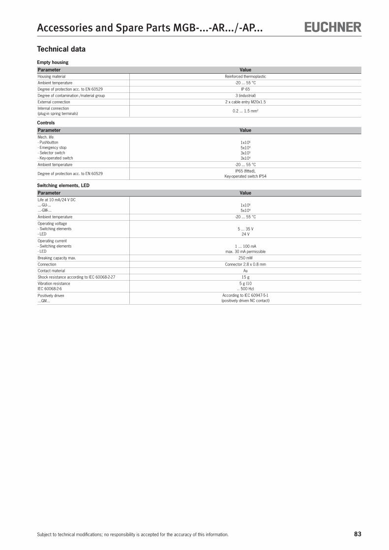
83
Accessories and Spare Parts MGB-...-AR.../-AP...
Subject to technical modifications; no responsibility is accepted for the accuracy of this information.
Technical data
Empty housing
Parameter ValueHousing material Reinforced thermoplastic
Ambient temperature -20 ... 55 °C
Degree of protection acc. to EN 60529 IP 65
Degree of contamination /material group 3 (industrial)
External connection 2 x cable entry M20x1.5
Internal connection (plug-in spring terminals)
0.2 ... 1.5 mm2
Controls
Parameter ValueMech. life- Pushbutton- Emergency stop- Selector switch- Key-operated switch
1x10⁶
5x10⁴
3x10⁵
3x10⁴
Ambient temperature -20 ... 55 °C
Degree of protection acc. to EN 60529IP65 (fitted),
Key-operated switch IP54
Switching elements, LED
Parameter ValueLife at 10 mA/24 V DC...-GU-......-GM-...
1x10⁶
5x10⁴
Ambient temperature -20 ... 55 °C
Operating voltage- Switching elements- LED
5 ... 35 V24 V
Operating current- Switching elements- LED
1 ... 100 mAmax. 30 mA permissible
Breaking capacity max. 250 mW
Connection Connector 2.8 x 0.8 mm
Contact material Au
Shock resistance according to IEC 60068-2-27 15 g
Vibration resistance IEC 60068-2-6
5 g (10.. 500 Hz)
Positively driven ...GM...
According to IEC 60947-5-1 (positively driven NC contact)
84
Accessories and Spare Parts MGB-...-AR.../-AP...
Subject to technical modifications; no responsibility is accepted for the accuracy of this information.
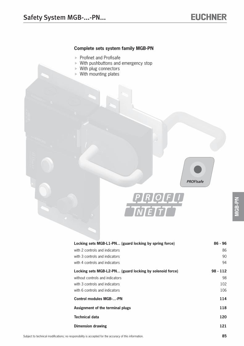
85
Safety System MGB-...-PN...
Subject to technical modifications; no responsibility is accepted for the accuracy of this information.
MG
B-P
N
Complete sets system family MGB-PN
Profinet and Profisafe With pushbuttons and emergency stop With plug connectors With mounting plates
Locking sets MGB-L1-PN... (guard locking by spring force) 86 - 96
with 2 controls and indicators 86
with 3 controls and indicators 90
with 4 controls and indicators 94
Locking sets MGB-L2-PN... (guard locking by solenoid force) 98 - 112
without controls and indicators 98
with 3 controls and indicators 102
with 6 controls and indicators 106
Control modules MGB-...-PN 114
Assignment of the terminal plugs 118
Technical data 120
Dimension drawing 121
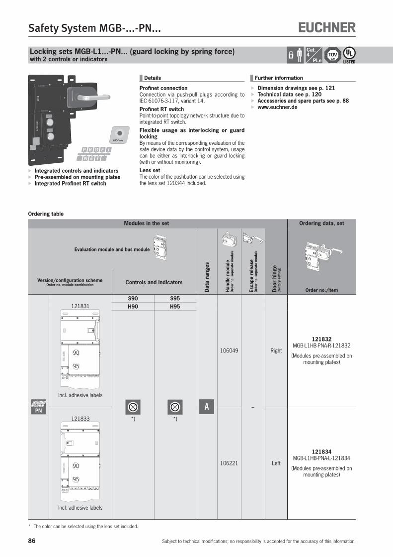
86
Safety System MGB-...-PN...
Subject to technical modifications; no responsibility is accepted for the accuracy of this information.
Locking sets MGB-L1...-PN... (guard locking by spring force)with 2 controls or indicators
Ordering table
Integrated controls and indicators Pre-assembled on mounting plates Integrated Profinet RT switch
Details
Profinet connectionConnection via push-pull plugs according to IEC 61076-3-117, variant 14.Profinet RT switchPoint-to-point topology network structure due to integrated RT switch.Flexible usage as interlocking or guard lockingBy means of the corresponding evaluation of the safe device data by the control system, usage can be either as interlocking or guard locking (with or without monitoring).Lens setThe color of the pushbutton can be selected using the lens set 120344 included.
Further information
Dimension drawings see p. 121 Technical data see p. 120 Accessories and spare parts see p. 88 www.euchner.de
Modules in the set
Doo
r hi
nge
(fac
tory
set
ting)
Ordering data, set
Order no./item
Evaluation module and bus module
Dat
a ra
nges
Han
dle
mod
ule
Ord
er n
o. s
epar
ate
mod
ule
Esca
pe r
elea
se
Ord
er n
o. s
epar
ate
mod
ule
Version/configuration schemeOrder no. module combination Controls and indicators
PN
121831
90
95
Incl. adhesive labels
S90 S95
A
106049
–
Right
121832 MGB-L1HB-PNA-R-121832
(Modules pre-assembled on mounting plates)
H90 H95
*) *)121833
90
95
Incl. adhesive labels
106221 Left
121834 MGB-L1HB-PNA-L-121834
(Modules pre-assembled on mounting plates)
* The color can be selected using the lens set included.
Cat.4
PLe
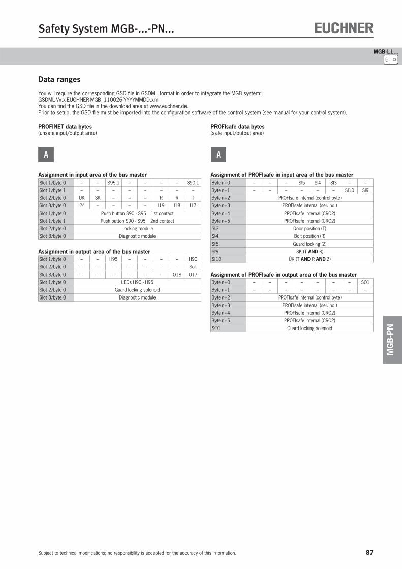
87
Safety System MGB-...-PN...
Subject to technical modifications; no responsibility is accepted for the accuracy of this information.
MG
B-P
N
41
MGB-L1...
Data ranges
You will require the corresponding GSD file in GSDML format in order to integrate the MGB system:GSDML-Vx.x-EUCHNER-MGB_110026-YYYYMMDD.xmlYou can find the GSD file in the download area at www.euchner.de.Prior to setup, the GSD file must be imported into the configuration software of the control system (see manual for your control system).
PROFINET data bytes(unsafe input/output area)
A
Assignment in input area of the bus masterSlot 1/byte 0 – – S95.1 – – – – S90.1
Slot 1/byte 1 – – – – – – – –
Slot 2/byte 0 ÜK SK – – – R R T
Slot 3/byte 0 I24 – – – – I19 I18 I17
Slot 1/byte 0 Push button S90 - S95 1st contact
Slot 1/byte 1 Push button S90 - S95 2nd contact
Slot 2/byte 0 Locking module
Slot 3/byte 0 Diagnostic module
Assignment in output area of the bus masterSlot 1/byte 0 – – H95 – – – – H90
Slot 2/byte 0 – – – – – – – Sol.
Slot 3/byte 0 – – – – – – O18 O17
Slot 1/byte 0 LEDs H90 - H95
Slot 2/byte 0 Guard locking solenoid
Slot 3/byte 0 Diagnostic module
PROFIsafe data bytes(safe input/output area)
A
Assignment of PROFIsafe in input area of the bus masterByte n+0 – – – SI5 SI4 SI3 – –
Byte n+1 – – – – – – SI10 SI9
Byte n+2 PROFIsafe internal (control byte)
Byte n+3 PROFIsafe internal (ser. no.)
Byte n+4 PROFIsafe internal (CRC2)
Byte n+5 PROFIsafe internal (CRC2)
SI3 Door position (T)
SI4 Bolt position (R)
SI5 Guard locking (Z)
SI9 SK (T AND R)
SI10 ÜK (T AND R AND Z)
Assignment of PROFIsafe in output area of the bus masterByte n+0 – – – – – – – SO1
Byte n+1 – – – – – – – –
Byte n+2 PROFIsafe internal (control byte)
Byte n+3 PROFIsafe internal (ser. no.)
Byte n+4 PROFIsafe internal (CRC2)
Byte n+5 PROFIsafe internal (CRC2)
SO1 Guard locking solenoid
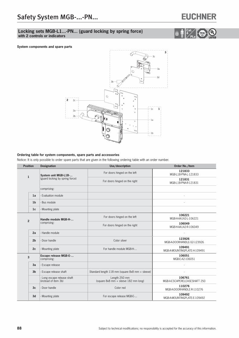
88
Safety System MGB-...-PN...
Subject to technical modifications; no responsibility is accepted for the accuracy of this information.
System components and spare parts
1c
1a
1b
1
2b
2c
2a
2
3c
3a
3d
3b
3
Ordering table for system components, spare parts and accessoriesNotice: It is only possible to order spare parts that are given in the following ordering table with an order number.
Position Designation Use/description Order No./item
1 System unit MGB-L1B-... (guard locking by spring force)
For doors hinged on the left 121833 MGB-L1B-PNA-L-121833
For doors hinged on the right 121831 MGB-L1B-PNA-R-121831
comprising:
1a - Evaluation module -
1b - Bus module -
1c - Mounting plate
2 Handle module MGB-H-...comprising:
For doors hinged on the left 106221 MGB-H-AA1A2-L-106221
For doors hinged on the right 106049 MGB-H-AA1A2-R-106049
2a - Handle module -
2b - Door handle Color silver 123926 MGB-A-DOORHANDLE-S2-123926
2c - Mounting plate For handle module MGB-H-... 109491 MGB-A-MOUNTINGPLATE-H-109491
3 Escape release MGB-E-...comprising:
106051 MGB-E-A2-106051
3a - Escape release -
3b - Escape release shaft Standard length 118 mm (square 8x8 mm + sleeve) -
- Long escape release shaft(instead of item 3b)
Length 250 mm (square 8x8 mm + sleeve 182 mm long)
106761 MGB-A-ESCAPERELEASESHAFT 250
3c - Door handle Color red 110276 MGB-A-DOORHANDLE-R-110276
3d - Mounting plate For escape release MGB-E-... 109492 MGB-A-MOUNTINGPLATE-E-109492
Locking sets MGB-L1...-PN... (guard locking by spring force)with 2 controls or indicators
Cat.4
PLe

89
Safety System MGB-...-PN...
Subject to technical modifications; no responsibility is accepted for the accuracy of this information.
MG
B-P
N
41
MGB-L1...

90
Safety System MGB-...-PN...
Subject to technical modifications; no responsibility is accepted for the accuracy of this information.
Locking sets MGB-L1...-PN... (guard locking by spring force)with 3 controls or indicators
Ordering table
Integrated controls and indicators Pre-assembled on mounting plates Integrated Profinet RT switch
Details
Profinet connectionConnection via push-pull plugs according to IEC 61076-3-117, variant 14, or 7/8" plugs ac-cording to ANSI/B93.55M-1981 and M12 plugs according to IEC 61076-2-101.Profinet RT switchPoint-to-point topology network structure due to integrated RT switch.Flexible usage as interlocking or guard lockingBy means of the corresponding evaluation of the safe device data by the control system, usage can be either as interlocking or guard locking (with or without monitoring).Illuminated emergency stopEmergency stop with illumination that can be controlled as required.
Lens setThe color of the pushbutton can be selected using the lens set 120344 included.
Further information
Dimension drawings see p. 121 Technical data see p. 120 Accessories and spare parts see p. 93 www.euchner.de
Modules in the set
Doo
r hi
nge
(fac
tory
set
ting)
Ordering data, set
Order no./item
Evaluation module and bus module
Dat
a ra
nges
Han
dle
mod
ule
Ord
er n
o. s
epar
ate
mod
ule
Esca
pe r
elea
se
Ord
er n
o. s
epar
ate
mod
ule
Version/configuration schemeOrder no. module combination Controls and indicators
PN
121851
90
9395
incl. adhesive labels, push-pull plugs
S93 S90 S95
A
106049
–
Right
121852 MGB-L1HB-PNA-R-121852
(Modules pre-assembled on mounting plates)
H93 H90 H95
STOP
*) *)121855
90
9395
incl. adhesive labels, push-pull plugs
106221 Left
121856 MGB-L1HB-PNA-L-121856
(Modules pre-assembled on mounting plates)
* The color can be selected using the lens set included.
Cat.4
PLe
(Continued on next page)
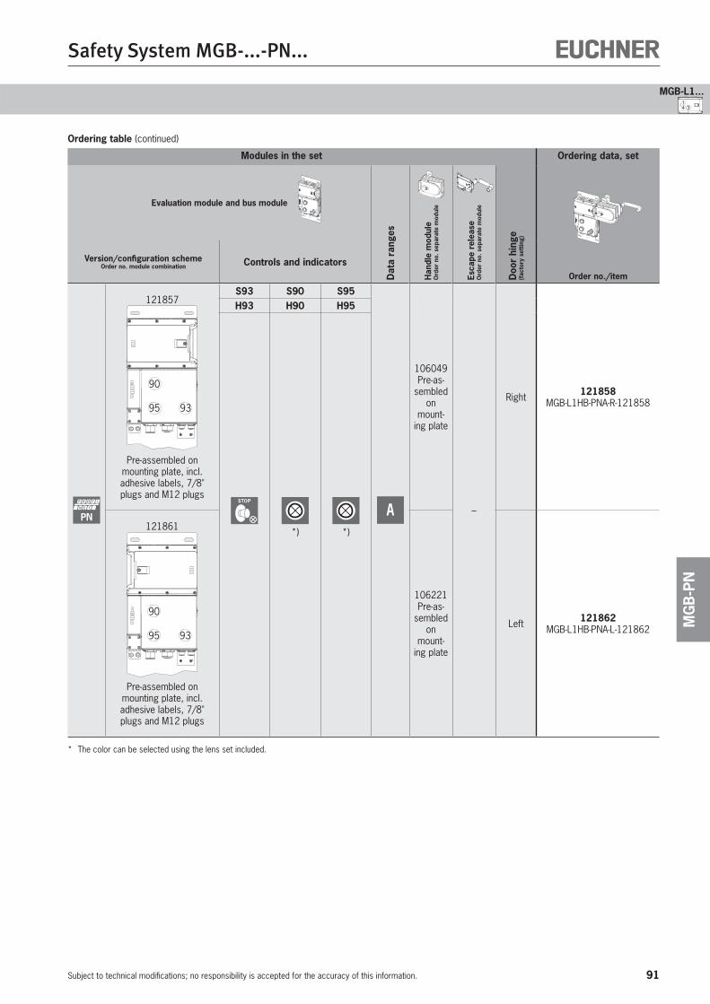
91
Safety System MGB-...-PN...
Subject to technical modifications; no responsibility is accepted for the accuracy of this information.
MG
B-P
N
4 31
MGB-L1...
Ordering table (continued)
Modules in the set
Doo
r hi
nge
(fac
tory
set
ting)
Ordering data, set
Order no./item
Evaluation module and bus module
Dat
a ra
nges
Han
dle
mod
ule
Ord
er n
o. s
epar
ate
mod
ule
Esca
pe r
elea
se
Ord
er n
o. s
epar
ate
mod
ule
Version/configuration schemeOrder no. module combination Controls and indicators
PN
121857
90
9395
Pre-assembled on mounting plate, incl. adhesive labels, 7/8" plugs and M12 plugs
S93 S90 S95
A
106049Pre-as-
sembled on
mount-ing plate
–
Right 121858 MGB-L1HB-PNA-R-121858
H93 H90 H95
STOP
*) *)121861
90
9395
Pre-assembled on mounting plate, incl. adhesive labels, 7/8" plugs and M12 plugs
106221Pre-as-
sembled on
mount-ing plate
Left 121862 MGB-L1HB-PNA-L-121862
* The color can be selected using the lens set included.

92
Safety System MGB-...-PN...
Subject to technical modifications; no responsibility is accepted for the accuracy of this information.
Locking sets MGB-L1...-PN... (guard locking by spring force)with 3 controls or indicators
Cat.4
PLe
Data ranges
You will require the corresponding GSD file in GSDML format in order to integrate the MGB system:GSDML-Vx.x-EUCHNER-MGB_110026-YYYYMMDD.xmlYou can find the GSD file in the download area at www.euchner.de.Prior to setup, the GSD file must be imported into the configuration software of the control system (see manual for your control system).
PROFINET data bytes(unsafe input/output area)
A
Assignment in input area of the bus masterSlot 1/byte 0 – – S95.1 – – – – S90.1
Slot 1/byte 1 – – – – – – – –
Slot 2/byte 0 – – – – – – – S93
Slot 3/byte 0 ÜK SK – – – R R T
Slot 4/byte 0 I24 – – – – I19 I18 I17
Slot 1/byte 0 Push button S90 - S95 1st contact
Slot 1/byte 1 Push button S90 - S95 2nd contact
Slot 2/byte 0 Emergency stop monitoring contact
Slot 3/byte 0 Locking module
Slot 4/byte 0 Diagnostic module
Assignment in output area of the bus masterSlot 1/byte 0 – – H95 – – – – H90
Slot 2/byte 0 – – – – – – – H93
Slot 3/byte 0 – – – – – – – Sol.
Slot 4/byte 0 – – – – – – O18 O17
Slot 1/byte 0 LEDs H90 - H95
Slot 2/byte 0 Emergency stop LED
Slot 3/byte 0 Guard locking solenoid
Slot 4/byte 0 Diagnostic module
PROFIsafe data bytes(safe input/output area)
A
Assignment of PROFIsafe in input area of the bus masterByte n+0 – – – SI5 SI4 SI3 – SI1
Byte n+1 – – – – – – SI10 SI9
Byte n+2 PROFIsafe internal (control byte)
Byte n+3 PROFIsafe internal (ser. no.)
Byte n+4 PROFIsafe internal (CRC2)
Byte n+5 PROFIsafe internal (CRC2)
SI1 Emergency stop S93
SI3 Door position (T)
SI4 Bolt position (R)
SI5 Guard locking (Z)
SI9 SK (T AND R)
SI10 ÜK (T AND R AND Z)
Assignment of PROFIsafe in output area of the bus masterByte n+0 – – – – – – – SO1
Byte n+1 – – – – – – – –
Byte n+2 PROFIsafe internal (control byte)
Byte n+3 PROFIsafe internal (ser. no.)
Byte n+4 PROFIsafe internal (CRC2)
Byte n+5 PROFIsafe internal (CRC2)
SO1 Guard locking solenoid
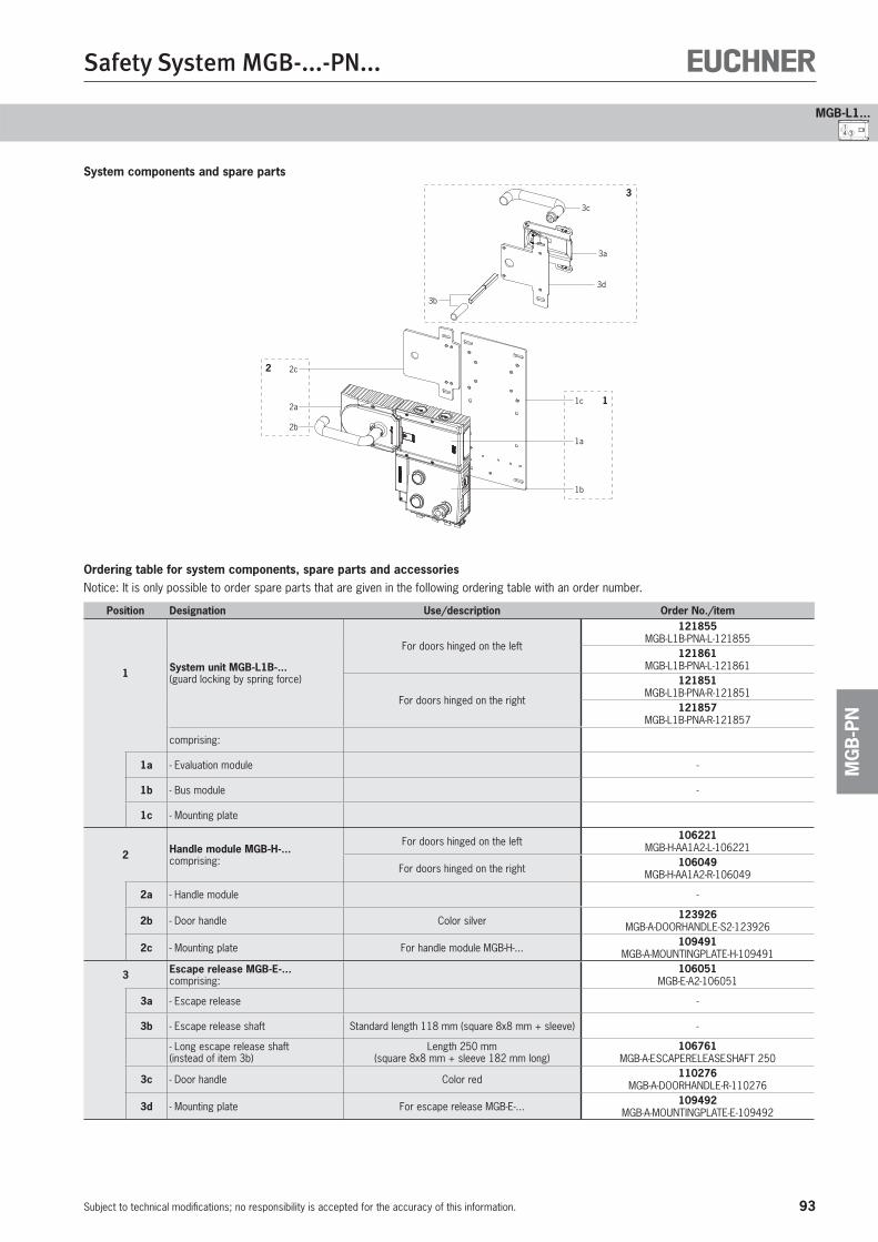
93
Safety System MGB-...-PN...
Subject to technical modifications; no responsibility is accepted for the accuracy of this information.
MG
B-P
N
4 31
MGB-L1...
System components and spare parts
1c
1a
1b
1
2b
2c
2a
2
3c
3a
3d
3b
3
Ordering table for system components, spare parts and accessoriesNotice: It is only possible to order spare parts that are given in the following ordering table with an order number.
Position Designation Use/description Order No./item
1 System unit MGB-L1B-... (guard locking by spring force)
For doors hinged on the left
121855 MGB-L1B-PNA-L-121855
121861 MGB-L1B-PNA-L-121861
For doors hinged on the right
121851 MGB-L1B-PNA-R-121851
121857 MGB-L1B-PNA-R-121857
comprising:
1a - Evaluation module -
1b - Bus module -
1c - Mounting plate
2 Handle module MGB-H-...comprising:
For doors hinged on the left 106221 MGB-H-AA1A2-L-106221
For doors hinged on the right 106049 MGB-H-AA1A2-R-106049
2a - Handle module -
2b - Door handle Color silver 123926 MGB-A-DOORHANDLE-S2-123926
2c - Mounting plate For handle module MGB-H-... 109491 MGB-A-MOUNTINGPLATE-H-109491
3 Escape release MGB-E-...comprising:
106051 MGB-E-A2-106051
3a - Escape release -
3b - Escape release shaft Standard length 118 mm (square 8x8 mm + sleeve) -
- Long escape release shaft(instead of item 3b)
Length 250 mm (square 8x8 mm + sleeve 182 mm long)
106761 MGB-A-ESCAPERELEASESHAFT 250
3c - Door handle Color red 110276 MGB-A-DOORHANDLE-R-110276
3d - Mounting plate For escape release MGB-E-... 109492 MGB-A-MOUNTINGPLATE-E-109492
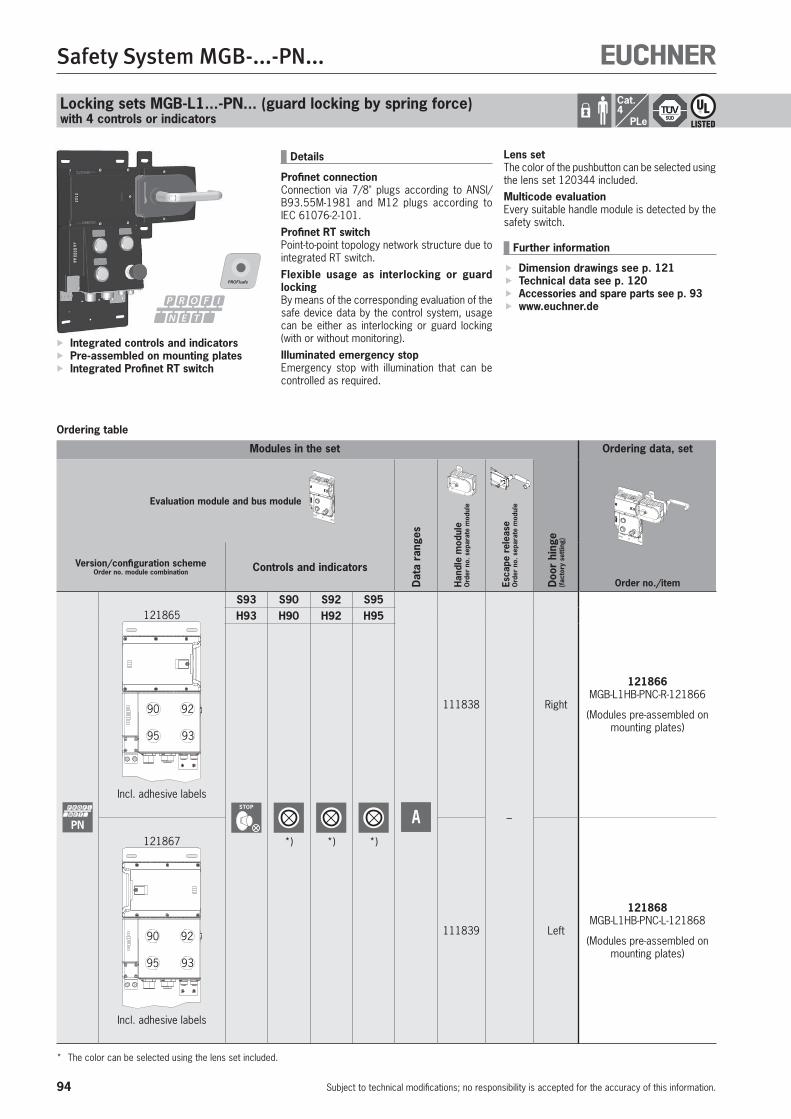
94
Safety System MGB-...-PN...
Subject to technical modifications; no responsibility is accepted for the accuracy of this information.
Locking sets MGB-L1...-PN... (guard locking by spring force)with 4 controls or indicators
Ordering table
Integrated controls and indicators Pre-assembled on mounting plates Integrated Profinet RT switch
Details
Profinet connectionConnection via 7/8" plugs according to ANSI/B93.55M-1981 and M12 plugs according to IEC 61076-2-101.Profinet RT switchPoint-to-point topology network structure due to integrated RT switch.Flexible usage as interlocking or guard lockingBy means of the corresponding evaluation of the safe device data by the control system, usage can be either as interlocking or guard locking (with or without monitoring).Illuminated emergency stopEmergency stop with illumination that can be controlled as required.
Lens setThe color of the pushbutton can be selected using the lens set 120344 included.Multicode evaluationEvery suitable handle module is detected by the safety switch.
Further information
Dimension drawings see p. 121 Technical data see p. 120 Accessories and spare parts see p. 93 www.euchner.de
Modules in the set
Doo
r hi
nge
(fac
tory
set
ting)
Ordering data, set
Order no./item
Evaluation module and bus module
Dat
a ra
nges
Han
dle
mod
ule
Ord
er n
o. s
epar
ate
mod
ule
Esca
pe r
elea
se
Ord
er n
o. s
epar
ate
mod
ule
Version/configuration schemeOrder no. module combination Controls and indicators
PN
121865
90 92
9395
Incl. adhesive labels
S93 S90 S92 S95
A
111838
–
Right
121866 MGB-L1HB-PNC-R-121866
(Modules pre-assembled on mounting plates)
H93 H90 H92 H95
STOP
*) *) *)121867
90 92
9395
Incl. adhesive labels
111839 Left
121868 MGB-L1HB-PNC-L-121868
(Modules pre-assembled on mounting plates)
* The color can be selected using the lens set included.
Cat.4
PLe
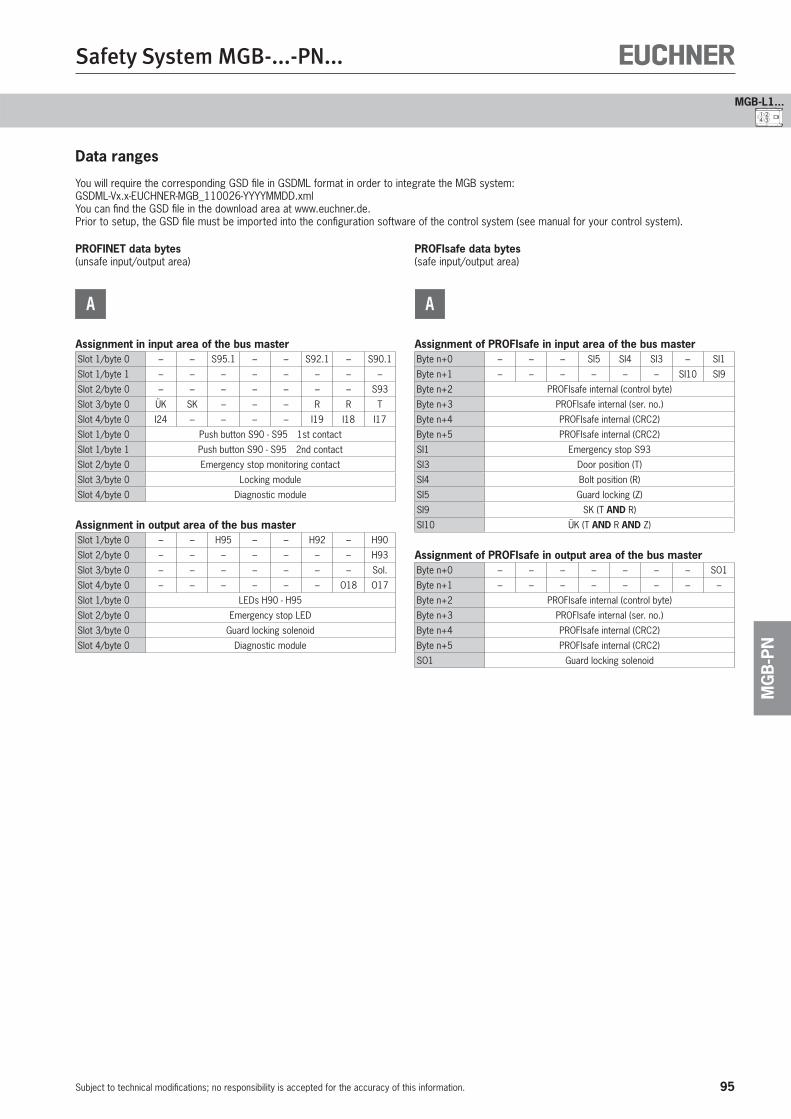
95
Safety System MGB-...-PN...
Subject to technical modifications; no responsibility is accepted for the accuracy of this information.
MG
B-P
N
4 321
MGB-L1...
Data ranges
You will require the corresponding GSD file in GSDML format in order to integrate the MGB system:GSDML-Vx.x-EUCHNER-MGB_110026-YYYYMMDD.xmlYou can find the GSD file in the download area at www.euchner.de.Prior to setup, the GSD file must be imported into the configuration software of the control system (see manual for your control system).
PROFINET data bytes(unsafe input/output area)
A
Assignment in input area of the bus masterSlot 1/byte 0 – – S95.1 – – S92.1 – S90.1
Slot 1/byte 1 – – – – – – – –
Slot 2/byte 0 – – – – – – – S93
Slot 3/byte 0 ÜK SK – – – R R T
Slot 4/byte 0 I24 – – – – I19 I18 I17
Slot 1/byte 0 Push button S90 - S95 1st contact
Slot 1/byte 1 Push button S90 - S95 2nd contact
Slot 2/byte 0 Emergency stop monitoring contact
Slot 3/byte 0 Locking module
Slot 4/byte 0 Diagnostic module
Assignment in output area of the bus masterSlot 1/byte 0 – – H95 – – H92 – H90
Slot 2/byte 0 – – – – – – – H93
Slot 3/byte 0 – – – – – – – Sol.
Slot 4/byte 0 – – – – – – O18 O17
Slot 1/byte 0 LEDs H90 - H95
Slot 2/byte 0 Emergency stop LED
Slot 3/byte 0 Guard locking solenoid
Slot 4/byte 0 Diagnostic module
PROFIsafe data bytes(safe input/output area)
A
Assignment of PROFIsafe in input area of the bus masterByte n+0 – – – SI5 SI4 SI3 – SI1
Byte n+1 – – – – – – SI10 SI9
Byte n+2 PROFIsafe internal (control byte)
Byte n+3 PROFIsafe internal (ser. no.)
Byte n+4 PROFIsafe internal (CRC2)
Byte n+5 PROFIsafe internal (CRC2)
SI1 Emergency stop S93
SI3 Door position (T)
SI4 Bolt position (R)
SI5 Guard locking (Z)
SI9 SK (T AND R)
SI10 ÜK (T AND R AND Z)
Assignment of PROFIsafe in output area of the bus masterByte n+0 – – – – – – – SO1
Byte n+1 – – – – – – – –
Byte n+2 PROFIsafe internal (control byte)
Byte n+3 PROFIsafe internal (ser. no.)
Byte n+4 PROFIsafe internal (CRC2)
Byte n+5 PROFIsafe internal (CRC2)
SO1 Guard locking solenoid
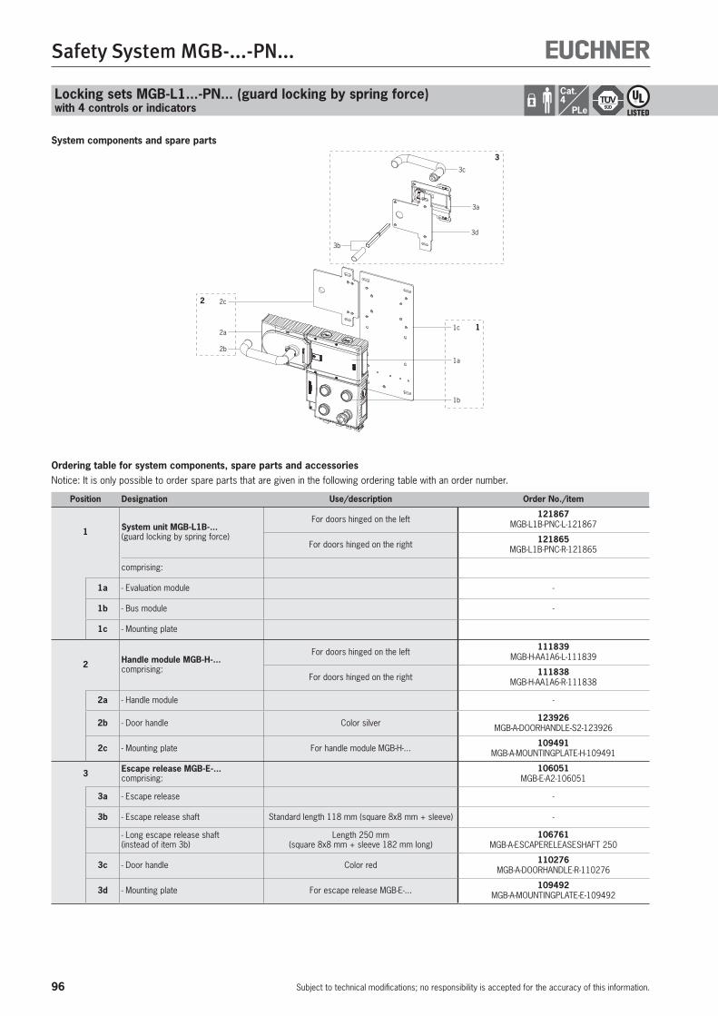
96
Safety System MGB-...-PN...
Subject to technical modifications; no responsibility is accepted for the accuracy of this information.
System components and spare parts
1c
1a
1b
1
2b
2c
2a
2
3c
3a
3d
3b
3
Ordering table for system components, spare parts and accessoriesNotice: It is only possible to order spare parts that are given in the following ordering table with an order number.
Position Designation Use/description Order No./item
1 System unit MGB-L1B-... (guard locking by spring force)
For doors hinged on the left 121867 MGB-L1B-PNC-L-121867
For doors hinged on the right 121865 MGB-L1B-PNC-R-121865
comprising:
1a - Evaluation module -
1b - Bus module -
1c - Mounting plate
2 Handle module MGB-H-...comprising:
For doors hinged on the left 111839 MGB-H-AA1A6-L-111839
For doors hinged on the right 111838 MGB-H-AA1A6-R-111838
2a - Handle module -
2b - Door handle Color silver 123926 MGB-A-DOORHANDLE-S2-123926
2c - Mounting plate For handle module MGB-H-... 109491 MGB-A-MOUNTINGPLATE-H-109491
3 Escape release MGB-E-...comprising:
106051 MGB-E-A2-106051
3a - Escape release -
3b - Escape release shaft Standard length 118 mm (square 8x8 mm + sleeve) -
- Long escape release shaft(instead of item 3b)
Length 250 mm (square 8x8 mm + sleeve 182 mm long)
106761 MGB-A-ESCAPERELEASESHAFT 250
3c - Door handle Color red 110276 MGB-A-DOORHANDLE-R-110276
3d - Mounting plate For escape release MGB-E-... 109492 MGB-A-MOUNTINGPLATE-E-109492
Locking sets MGB-L1...-PN... (guard locking by spring force)with 4 controls or indicators
Cat.4
PLe

97
Safety System MGB-...-PN...
Subject to technical modifications; no responsibility is accepted for the accuracy of this information.
MG
B-P
N
4 321
MGB-L1...

98
Safety System MGB-...-PN...
Subject to technical modifications; no responsibility is accepted for the accuracy of this information.
Locking sets MGB-L2...-PN... (guard locking by solenoid force)without controls or indicators
Ordering table
Pre-assembled on mounting plates Integrated Profinet RT switch
Details
Profinet connectionConnection via push-pull plugs according to IEC 61076-3-117, variant 14.Profinet RT switchPoint-to-point topology network structure due to integrated RT switch.Flexible usage as interlocking or guard lockingBy means of the corresponding evaluation of the safe device data by the control system, usage can be either as interlocking or guard locking (with or without monitoring).
Cat.4
PLe
Modules in the set
Doo
r hi
nge
(fac
tory
set
ting)
Ordering data, set
Order no./item
Evaluation module and bus module
Dat
a ra
nges
Han
dle
mod
ule
Ord
er n
o. s
epar
ate
mod
ule
Esca
pe r
elea
se
Ord
er n
o. s
epar
ate
mod
ule
Version/configuration schemeOrder no. module combination Controls and indicators
PN
114044
– A
106049
–
Right
113988 MGB-L2HB-PNA-R-113988
(Modules pre-assembled on mounting plates)
114045
106221 Left
113989 MGB-L2HB-PNA-L-113989
(Modules pre-assembled on mounting plates)
Further information
Dimension drawings see p. 121 Technical data see p. 120 Accessories and spare parts see p. 100 www.euchner.de
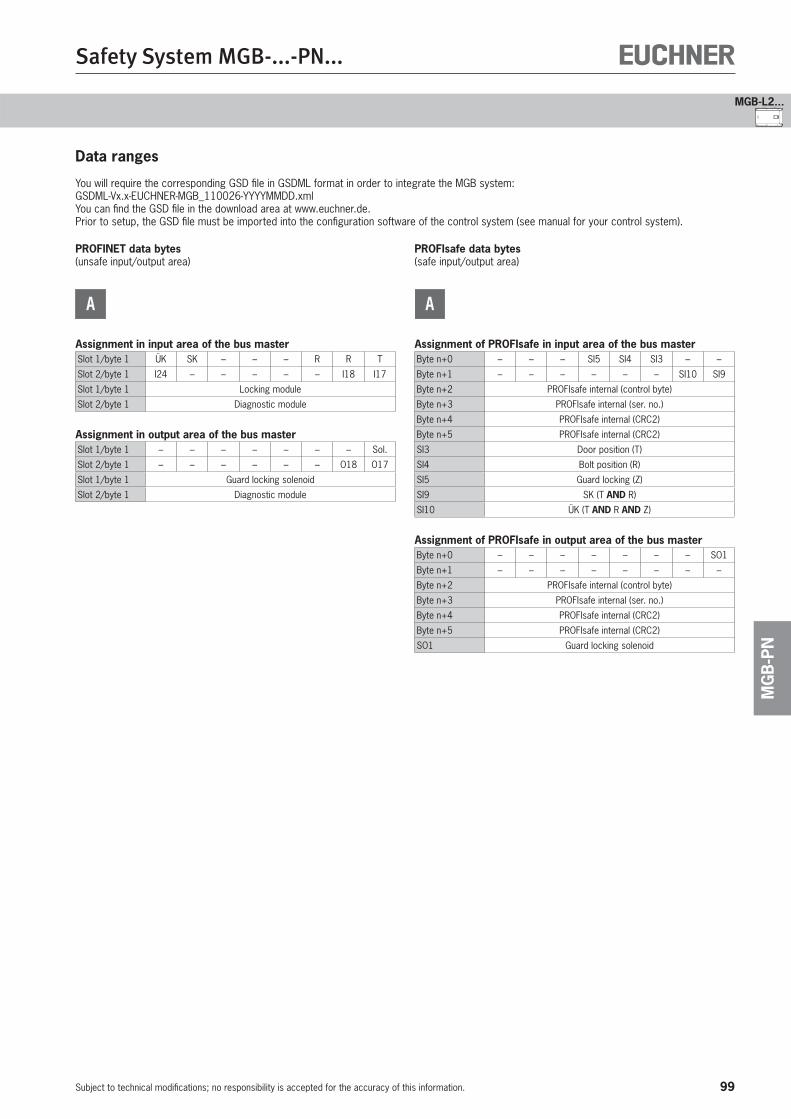
99
Safety System MGB-...-PN...
Subject to technical modifications; no responsibility is accepted for the accuracy of this information.
MG
B-P
N
MGB-L2...
Data ranges
You will require the corresponding GSD file in GSDML format in order to integrate the MGB system:GSDML-Vx.x-EUCHNER-MGB_110026-YYYYMMDD.xmlYou can find the GSD file in the download area at www.euchner.de.Prior to setup, the GSD file must be imported into the configuration software of the control system (see manual for your control system).
PROFINET data bytes(unsafe input/output area)
A
Assignment in input area of the bus masterSlot 1/byte 1 ÜK SK – – – R R T
Slot 2/byte 1 I24 – – – – – I18 I17
Slot 1/byte 1 Locking module
Slot 2/byte 1 Diagnostic module
Assignment in output area of the bus masterSlot 1/byte 1 – – – – – – – Sol.
Slot 2/byte 1 – – – – – – O18 O17
Slot 1/byte 1 Guard locking solenoid
Slot 2/byte 1 Diagnostic module
PROFIsafe data bytes(safe input/output area)
A
Assignment of PROFIsafe in input area of the bus masterByte n+0 – – – SI5 SI4 SI3 – –
Byte n+1 – – – – – – SI10 SI9
Byte n+2 PROFIsafe internal (control byte)
Byte n+3 PROFIsafe internal (ser. no.)
Byte n+4 PROFIsafe internal (CRC2)
Byte n+5 PROFIsafe internal (CRC2)
SI3 Door position (T)
SI4 Bolt position (R)
SI5 Guard locking (Z)
SI9 SK (T AND R)
SI10 ÜK (T AND R AND Z)
Assignment of PROFIsafe in output area of the bus masterByte n+0 – – – – – – – SO1
Byte n+1 – – – – – – – –
Byte n+2 PROFIsafe internal (control byte)
Byte n+3 PROFIsafe internal (ser. no.)
Byte n+4 PROFIsafe internal (CRC2)
Byte n+5 PROFIsafe internal (CRC2)
SO1 Guard locking solenoid

100
Safety System MGB-...-PN...
Subject to technical modifications; no responsibility is accepted for the accuracy of this information.
System components and spare parts
Ordering table for system components, spare parts and accessoriesNotice: It is only possible to order spare parts that are given in the following ordering table with an order number.
Position Designation Use/description Order No./item
1 System unit MGB-L2B-...(guard locking by solenoid force)
For doors hinged on the left 114044 MGB-L2B-PNA-L-114044
For doors hinged on the right 114045 MGB-L2B-PNA-R-114045
comprising:
1a - Evaluation module -
1b - Bus module -
1c - Mounting plate
2 Handle module MGB-H-...comprising:
For doors hinged on the left 106221 MGB-H-AA1A2-L-106221
For doors hinged on the right 106049 MGB-H-AA1A2-R-106049
2a - Handle module -
2b - Door handle Color silver 123926 MGB-A-DOORHANDLE-S2-123926
2c - Mounting plate For handle module MGB-H-... 109491 MGB-A-MOUNTINGPLATE-H-109491
3 Escape release MGB-E-...comprising:
106051 MGB-E-A2-106051
3a - Escape release -
3b - Escape release shaft Standard length 118 mm (square + sleeve) -
- Long escape release shaft(instead of item 3b)
Length 250 mm (square 8x8 mm + sleeve 182 mm long)
106761 MGB-A-ESCAPERELEASESHAFT 250
3c - Door handle Color red 110276 MGB-A-DOORHANDLE-R-110276
3d - Mounting plate For escape release MGB-E-... 109492 MGB-A-MOUNTINGPLATE-E-109492
1c
1a
1b
1
2b
2c
2a
2
3c
3a
3d
3b
3
Locking sets MGB-L2...-PN... (guard locking by solenoid force)without controls or indicators
Cat.4
PLe

101
Safety System MGB-...-PN...
Subject to technical modifications; no responsibility is accepted for the accuracy of this information.
MG
B-P
N
MGB-L2...
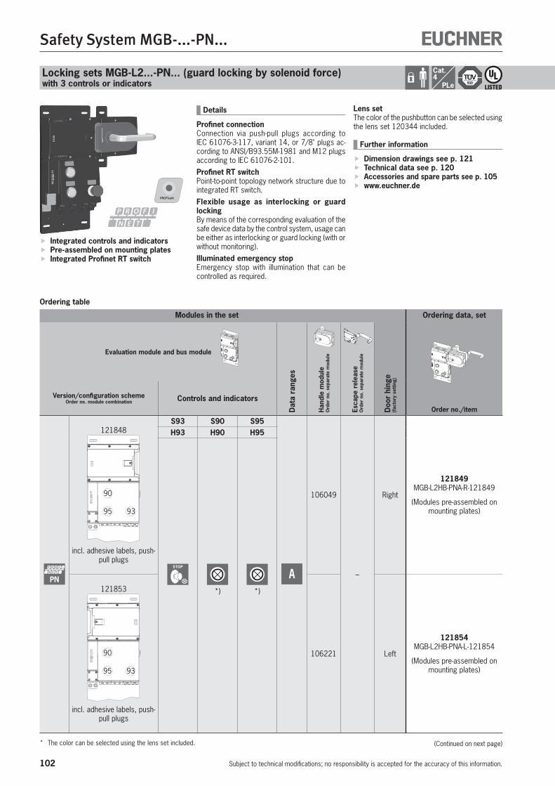
102
Safety System MGB-...-PN...
Subject to technical modifications; no responsibility is accepted for the accuracy of this information.
Locking sets MGB-L2...-PN... (guard locking by solenoid force)with 3 controls or indicators
Ordering table
Integrated controls and indicators Pre-assembled on mounting plates Integrated Profinet RT switch
Details
Profinet connectionConnection via push-pull plugs according to IEC 61076-3-117, variant 14, or 7/8" plugs ac-cording to ANSI/B93.55M-1981 and M12 plugs according to IEC 61076-2-101.Profinet RT switchPoint-to-point topology network structure due to integrated RT switch.Flexible usage as interlocking or guard lockingBy means of the corresponding evaluation of the safe device data by the control system, usage can be either as interlocking or guard locking (with or without monitoring).Illuminated emergency stopEmergency stop with illumination that can be controlled as required.
Cat.4
PLe
Modules in the set
Doo
r hi
nge
(fac
tory
set
ting)
Ordering data, set
Order no./item
Evaluation module and bus module
Dat
a ra
nges
Han
dle
mod
ule
Ord
er n
o. s
epar
ate
mod
ule
Esca
pe r
elea
se
Ord
er n
o. s
epar
ate
mod
ule
Version/configuration schemeOrder no. module combination Controls and indicators
PN
121848
90
9395
incl. adhesive labels, push-pull plugs
S93 S90 S95
A
106049
–
Right
121849 MGB-L2HB-PNA-R-121849
(Modules pre-assembled on mounting plates)
H93 H90 H95
STOP
*) *)121853
90
9395
incl. adhesive labels, push-pull plugs
106221 Left
121854 MGB-L2HB-PNA-L-121854
(Modules pre-assembled on mounting plates)
* The color can be selected using the lens set included.
Lens setThe color of the pushbutton can be selected using the lens set 120344 included.
Further information
Dimension drawings see p. 121 Technical data see p. 120 Accessories and spare parts see p. 105 www.euchner.de
(Continued on next page)

103
Safety System MGB-...-PN...
Subject to technical modifications; no responsibility is accepted for the accuracy of this information.
MG
B-P
N
4 31
MGB-L2...
Ordering table (continued)
Modules in the set
Doo
r hi
nge
(fac
tory
set
ting)
Ordering data, set
Order no./item
Evaluation module and bus module
Dat
a ra
nges
Han
dle
mod
ule
Ord
er n
o. s
epar
ate
mod
ule
Esca
pe r
elea
se
Ord
er n
o. s
epar
ate
mod
ule
Version/configuration schemeOrder no. module combination Controls and indicators
PN
121859
90
9395
Pre-assembled on mount-ing plate, incl. adhesive labels, 7/8" plugs and
M12 plugs
S93 S90 S95
A
106049Pre-as-
sembled on
mount-ing plate
–
Right 121860 MGB-L2HB-PNA-R-121860
H93 H90 H95
STOP
*) *)121863
90
9395
Pre-assembled on mount-ing plate, incl. adhesive labels, 7/8" plugs and
M12 plugs
106221Pre-as-
sembled on
mount-ing plate
Left 121864 MGB-L2HB-PNA-L-121864
* The color can be selected using the lens set included.
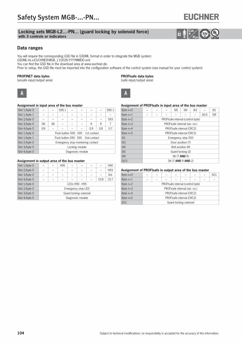
104
Safety System MGB-...-PN...
Subject to technical modifications; no responsibility is accepted for the accuracy of this information.
Locking sets MGB-L2...-PN... (guard locking by solenoid force)with 3 controls or indicators
Cat.4
PLe
Data ranges
You will require the corresponding GSD file in GSDML format in order to integrate the MGB system:GSDML-Vx.x-EUCHNER-MGB_110026-YYYYMMDD.xmlYou can find the GSD file in the download area at www.euchner.de.Prior to setup, the GSD file must be imported into the configuration software of the control system (see manual for your control system).
PROFINET data bytes(unsafe input/output area)
A
Assignment in input area of the bus masterSlot 1/byte 0 – – S95.1 – – – – S90.1
Slot 1/byte 1 – – – – – – – –
Slot 2/byte 0 – – – – – – – S93
Slot 3/byte 0 ÜK SK – – – R R T
Slot 4/byte 0 I24 – – – – I19 I18 I17
Slot 1/byte 0 Push button S90 - S95 1st contact
Slot 1/byte 1 Push button S90 - S95 2nd contact
Slot 2/byte 0 Emergency stop monitoring contact
Slot 3/byte 0 Locking module
Slot 4/byte 0 Diagnostic module
Assignment in output area of the bus masterSlot 1/byte 0 – – H95 – – – – H90
Slot 2/byte 0 – – – – – – – H93
Slot 3/byte 0 – – – – – – – Sol.
Slot 4/byte 0 – – – – – – O18 O17
Slot 1/byte 0 LEDs H90 - H95
Slot 2/byte 0 Emergency stop LED
Slot 3/byte 0 Guard locking solenoid
Slot 4/byte 0 Diagnostic module
PROFIsafe data bytes(safe input/output area)
A
Assignment of PROFIsafe in input area of the bus masterByte n+0 – – – SI5 SI4 SI3 – SI1
Byte n+1 – – – – – – SI10 SI9
Byte n+2 PROFIsafe internal (control byte)
Byte n+3 PROFIsafe internal (ser. no.)
Byte n+4 PROFIsafe internal (CRC2)
Byte n+5 PROFIsafe internal (CRC2)
SI1 Emergency stop S93
SI3 Door position (T)
SI4 Bolt position (R)
SI5 Guard locking (Z)
SI9 SK (T AND R)
SI10 ÜK (T AND R AND Z)
Assignment of PROFIsafe in output area of the bus masterByte n+0 – – – – – – – SO1
Byte n+1 – – – – – – – –
Byte n+2 PROFIsafe internal (control byte)
Byte n+3 PROFIsafe internal (ser. no.)
Byte n+4 PROFIsafe internal (CRC2)
Byte n+5 PROFIsafe internal (CRC2)
SO1 Guard locking solenoid
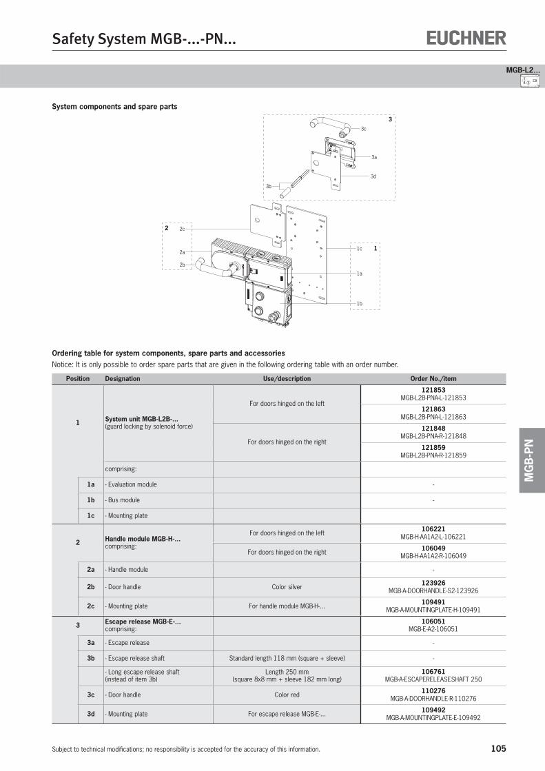
105
Safety System MGB-...-PN...
Subject to technical modifications; no responsibility is accepted for the accuracy of this information.
MG
B-P
N
4 31
MGB-L2...
System components and spare parts
Ordering table for system components, spare parts and accessoriesNotice: It is only possible to order spare parts that are given in the following ordering table with an order number.
Position Designation Use/description Order No./item
1 System unit MGB-L2B-...(guard locking by solenoid force)
For doors hinged on the left
121853 MGB-L2B-PNA-L-121853
121863 MGB-L2B-PNA-L-121863
For doors hinged on the right
121848 MGB-L2B-PNA-R-121848
121859 MGB-L2B-PNA-R-121859
comprising:
1a - Evaluation module -
1b - Bus module -
1c - Mounting plate
2 Handle module MGB-H-...comprising:
For doors hinged on the left 106221 MGB-H-AA1A2-L-106221
For doors hinged on the right 106049 MGB-H-AA1A2-R-106049
2a - Handle module -
2b - Door handle Color silver 123926 MGB-A-DOORHANDLE-S2-123926
2c - Mounting plate For handle module MGB-H-... 109491 MGB-A-MOUNTINGPLATE-H-109491
3 Escape release MGB-E-...comprising:
106051 MGB-E-A2-106051
3a - Escape release -
3b - Escape release shaft Standard length 118 mm (square + sleeve) -
- Long escape release shaft(instead of item 3b)
Length 250 mm (square 8x8 mm + sleeve 182 mm long)
106761 MGB-A-ESCAPERELEASESHAFT 250
3c - Door handle Color red 110276 MGB-A-DOORHANDLE-R-110276
3d - Mounting plate For escape release MGB-E-... 109492 MGB-A-MOUNTINGPLATE-E-109492
1c
1a
1b
1
2b
2c
2a
2
3c
3a
3d
3b
3
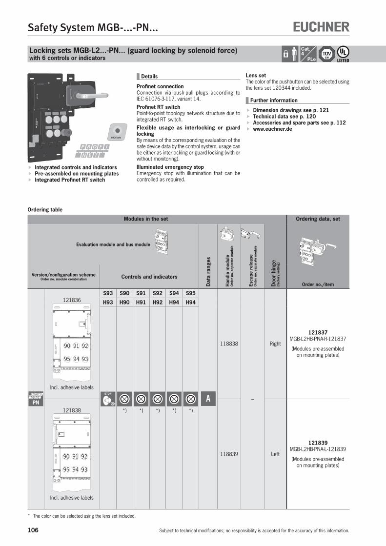
106
Safety System MGB-...-PN...
Subject to technical modifications; no responsibility is accepted for the accuracy of this information.
Locking sets MGB-L2...-PN... (guard locking by solenoid force)with 6 controls or indicators
Ordering table
Integrated controls and indicators Pre-assembled on mounting plates Integrated Profinet RT switch
Details
Profinet connectionConnection via push-pull plugs according to IEC 61076-3-117, variant 14.Profinet RT switchPoint-to-point topology network structure due to integrated RT switch.Flexible usage as interlocking or guard lockingBy means of the corresponding evaluation of the safe device data by the control system, usage can be either as interlocking or guard locking (with or without monitoring).Illuminated emergency stopEmergency stop with illumination that can be controlled as required.
Cat.4
PLe
Modules in the set
Doo
r hi
nge
(fac
tory
set
ting)
Ordering data, set
Order no./item
Evaluation module and bus module
Dat
a ra
nges
Han
dle
mod
ule
Ord
er n
o. s
epar
ate
mod
ule
Esca
pe r
elea
se
Ord
er n
o. s
epar
ate
mod
ule
Version/configuration schemeOrder no. module combination Controls and indicators
PN
121836
90 91 92
9395 94
Incl. adhesive labels
S93 S90 S91 S92 S94 S95
A
118838
–
Right
121837 MGB-L2HB-PNA-R-121837
(Modules pre-assembled on mounting plates)
H93 H90 H91 H92 H94 H94
STOP
*) *) *) *) *)121838
90 91 92
9395 94
Incl. adhesive labels
118839 Left
121839 MGB-L2HB-PNA-L-121839
(Modules pre-assembled on mounting plates)
* The color can be selected using the lens set included.
Lens setThe color of the pushbutton can be selected using the lens set 120344 included.
Further information
Dimension drawings see p. 121 Technical data see p. 120 Accessories and spare parts see p. 112 www.euchner.de

107
Safety System MGB-...-PN...
Subject to technical modifications; no responsibility is accepted for the accuracy of this information.
MG
B-P
N
1
MGB-L2...
Data ranges
You will require the corresponding GSD file in GSDML format in order to integrate the MGB system:GSDML-Vx.x-EUCHNER-MGB_110026-YYYYMMDD.xmlYou can find the GSD file in the download area at www.euchner.de.Prior to setup, the GSD file must be imported into the configuration software of the control system (see manual for your control system).
PROFINET data bytes(unsafe input/output area)
A
Assignment in input area of the bus masterSlot 1/byte 0 – – S95.1 S94.1 – S92.1 S91.1 S90.1
Slot 1/byte 1 – – – – – – – –
Slot 2/byte 0 – – – – – – – S93
Slot 3/byte 0 ÜK SK – – – R R T
Slot 4/byte 0 I24 – – – – I19 I18 I17
Slot 1/byte 0 Push button S90 - S95 1st contact
Slot 1/byte 1 Push button S90 - S95 2nd contact
Slot 2/byte 0 Emergency stop monitoring contact
Slot 3/byte 0 Locking module
Slot 4/byte 0 Diagnostic module
Assignment in output area of the bus masterSlot 1/byte 0 – – H95 H94 – H92 H91 H90
Slot 2/byte 0 – – – – – – – H93
Slot 3/byte 0 – – – – – – – Sol.
Slot 4/byte 0 – – – – – – O18 O17
Slot 1/byte 0 LEDs H90 - H95
Slot 2/byte 0 Emergency stop LED
Slot 3/byte 0 Guard locking solenoid
Slot 4/byte 0 Diagnostic module
PROFIsafe data bytes(safe input/output area)
A
Assignment of PROFIsafe in input area of the bus masterByte n+0 – – – SI5 SI4 SI3 – SI1
Byte n+1 – – – – – – SI10 SI9
Byte n+2 PROFIsafe internal (control byte)
Byte n+3 PROFIsafe internal (ser. no.)
Byte n+4 PROFIsafe internal (CRC2)
Byte n+5 PROFIsafe internal (CRC2)
SI1 Emergency stop S93
SI3 Door position (T)
SI4 Bolt position (R)
SI5 Guard locking (Z)
SI9 SK (T AND R)
SI10 ÜK (T AND R AND Z)
Assignment of PROFIsafe in output area of the bus masterByte n+0 – – – – – – – SO1
Byte n+1 – – – – – – – –
Byte n+2 PROFIsafe internal (control byte)
Byte n+3 PROFIsafe internal (ser. no.)
Byte n+4 PROFIsafe internal (CRC2)
Byte n+5 PROFIsafe internal (CRC2)
SO1 Guard locking solenoid
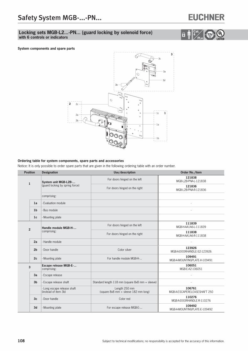
108
Safety System MGB-...-PN...
Subject to technical modifications; no responsibility is accepted for the accuracy of this information.
System components and spare parts
1c
1a
1b
1
2b
2c
2a
2
3c
3a
3d
3b
3
Ordering table for system components, spare parts and accessoriesNotice: It is only possible to order spare parts that are given in the following ordering table with an order number.
Position Designation Use/description Order No./item
1 System unit MGB-L2B-... (guard locking by spring force)
For doors hinged on the left 121838 MGB-L2B-PNA-L-121838
For doors hinged on the right 121836 MGB-L2B-PNA-R-121836
comprising:
1a - Evaluation module -
1b - Bus module -
1c - Mounting plate
2 Handle module MGB-H-...comprising:
For doors hinged on the left 111839 MGB-H-AA1A6-L-111839
For doors hinged on the right 111838 MGB-H-AA1A6-R-111838
2a - Handle module -
2b - Door handle Color silver 123926 MGB-A-DOORHANDLE-S2-123926
2c - Mounting plate For handle module MGB-H-... 109491 MGB-A-MOUNTINGPLATE-H-109491
3 Escape release MGB-E-...comprising:
106051 MGB-E-A2-106051
3a - Escape release -
3b - Escape release shaft Standard length 118 mm (square 8x8 mm + sleeve) -
- Long escape release shaft(instead of item 3b)
Length 250 mm (square 8x8 mm + sleeve 182 mm long)
106761 MGB-A-ESCAPERELEASESHAFT 250
3c - Door handle Color red 110276 MGB-A-DOORHANDLE-R-110276
3d - Mounting plate For escape release MGB-E-... 109492 MGB-A-MOUNTINGPLATE-E-109492
Locking sets MGB-L2...-PN... (guard locking by solenoid force)with 6 controls or indicators
Cat.4
PLe

109
Safety System MGB-...-PN...
Subject to technical modifications; no responsibility is accepted for the accuracy of this information.
MG
B-P
N
1
MGB-L2...
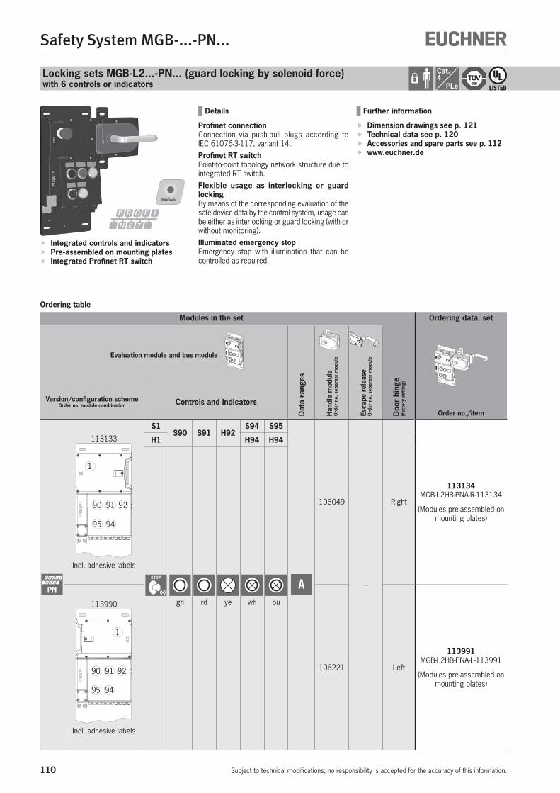
110
Safety System MGB-...-PN...
Subject to technical modifications; no responsibility is accepted for the accuracy of this information.
Locking sets MGB-L2...-PN... (guard locking by solenoid force)with 6 controls or indicators
Ordering table
Integrated controls and indicators Pre-assembled on mounting plates Integrated Profinet RT switch
Details
Profinet connectionConnection via push-pull plugs according to IEC 61076-3-117, variant 14.Profinet RT switchPoint-to-point topology network structure due to integrated RT switch.Flexible usage as interlocking or guard lockingBy means of the corresponding evaluation of the safe device data by the control system, usage can be either as interlocking or guard locking (with or without monitoring).Illuminated emergency stopEmergency stop with illumination that can be controlled as required.
Cat.4
PLe
Modules in the set
Doo
r hi
nge
(fac
tory
set
ting)
Ordering data, set
Order no./item
Evaluation module and bus module
Dat
a ra
nges
Han
dle
mod
ule
Ord
er n
o. s
epar
ate
mod
ule
Esca
pe r
elea
se
Ord
er n
o. s
epar
ate
mod
ule
Version/configuration schemeOrder no. module combination Controls and indicators
PN
113133
90
1
91 92
95 94
Incl. adhesive labels
S1S90 S91 H92
S94 S95
A
106049
–
Right
113134 MGB-L2HB-PNA-R-113134
(Modules pre-assembled on mounting plates)
H1 H94 H94
STOP
gn rd ye wh bu113990
90
1
91 92
95 94
Incl. adhesive labels
106221 Left
113991 MGB-L2HB-PNA-L-113991
(Modules pre-assembled on mounting plates)
Further information
Dimension drawings see p. 121 Technical data see p. 120 Accessories and spare parts see p. 112 www.euchner.de
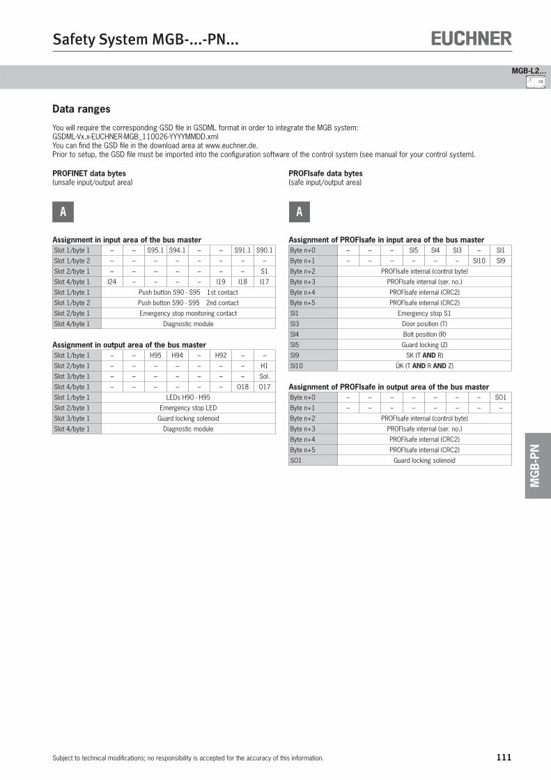
111
Safety System MGB-...-PN...
Subject to technical modifications; no responsibility is accepted for the accuracy of this information.
MG
B-P
N
1
MGB-L2...
Data ranges
You will require the corresponding GSD file in GSDML format in order to integrate the MGB system:GSDML-Vx.x-EUCHNER-MGB_110026-YYYYMMDD.xmlYou can find the GSD file in the download area at www.euchner.de.Prior to setup, the GSD file must be imported into the configuration software of the control system (see manual for your control system).
PROFINET data bytes(unsafe input/output area)
A
Assignment in input area of the bus masterSlot 1/byte 1 – – S95.1 S94.1 – – S91.1 S90.1
Slot 1/byte 2 – – – – – – – –
Slot 2/byte 1 – – – – – – – S1
Slot 4/byte 1 I24 – – – – I19 I18 I17
Slot 1/byte 1 Push button S90 - S95 1st contact
Slot 1/byte 2 Push button S90 - S95 2nd contact
Slot 2/byte 1 Emergency stop monitoring contact
Slot 4/byte 1 Diagnostic module
Assignment in output area of the bus masterSlot 1/byte 1 – – H95 H94 – H92 – –
Slot 2/byte 1 – – – – – – – H1
Slot 3/byte 1 – – – – – – – Sol.
Slot 4/byte 1 – – – – – – O18 O17
Slot 1/byte 1 LEDs H90 - H95
Slot 2/byte 1 Emergency stop LED
Slot 3/byte 1 Guard locking solenoid
Slot 4/byte 1 Diagnostic module
PROFIsafe data bytes(safe input/output area)
A
Assignment of PROFIsafe in input area of the bus masterByte n+0 – – – SI5 SI4 SI3 – SI1
Byte n+1 – – – – – – SI10 SI9
Byte n+2 PROFIsafe internal (control byte)
Byte n+3 PROFIsafe internal (ser. no.)
Byte n+4 PROFIsafe internal (CRC2)
Byte n+5 PROFIsafe internal (CRC2)
SI1 Emergency stop S1
SI3 Door position (T)
SI4 Bolt position (R)
SI5 Guard locking (Z)
SI9 SK (T AND R)
SI10 ÜK (T AND R AND Z)
Assignment of PROFIsafe in output area of the bus masterByte n+0 – – – – – – – SO1
Byte n+1 – – – – – – – –
Byte n+2 PROFIsafe internal (control byte)
Byte n+3 PROFIsafe internal (ser. no.)
Byte n+4 PROFIsafe internal (CRC2)
Byte n+5 PROFIsafe internal (CRC2)
SO1 Guard locking solenoid

112
Safety System MGB-...-PN...
Subject to technical modifications; no responsibility is accepted for the accuracy of this information.
Locking sets MGB-L2...-PN... (guard locking by solenoid force)with 6 controls or indicators
Cat.4
PLe
System components and spare parts
Ordering table for system components, spare parts and accessoriesNotice: It is only possible to order spare parts that are given in the following ordering table with an order number.
Position Designation Use/description Order No./item
1 System unit MGB-L2B-...(guard locking by solenoid force)
For doors hinged on the left 113990 MGB-L2B-PNA-L-113990
For doors hinged on the right 113133 MGB-L2B-PNA-R-113133
comprising:
1a - Evaluation module -
1b - Bus module -
1c - Mounting plate
2 Handle module MGB-H-...comprising:
For doors hinged on the left 106221 MGB-H-AA1A2-L-106221
For doors hinged on the right 106049 MGB-H-AA1A2-R-106049
2a - Handle module -
2b - Door handle Color silver 123926 MGB-A-DOORHANDLE-S2-123926
2c - Mounting plate For handle module MGB-H-... 109491 MGB-A-MOUNTINGPLATE-H-109491
3 Escape release MGB-E-...comprising:
106051 MGB-E-A2-106051
3a - Escape release -
3b - Escape release shaft Standard length 118 mm (square + sleeve) -
- Long escape release shaft(instead of item 3b)
Length 250 mm (square 8x8 mm + sleeve 182 mm long)
106761 MGB-A-ESCAPERELEASESHAFT 250
3c - Door handle Color red 110276 MGB-A-DOORHANDLE-R-110276
3d - Mounting plate For escape release MGB-E-... 109492 MGB-A-MOUNTINGPLATE-E-109492
1c
1a
1b
1
2b
2c
2a
2
3c
3a
3d
3b
3
113
Safety System MGB-...-PN...
Subject to technical modifications; no responsibility is accepted for the accuracy of this information.
MG
B-P
N
1
MGB-L2...
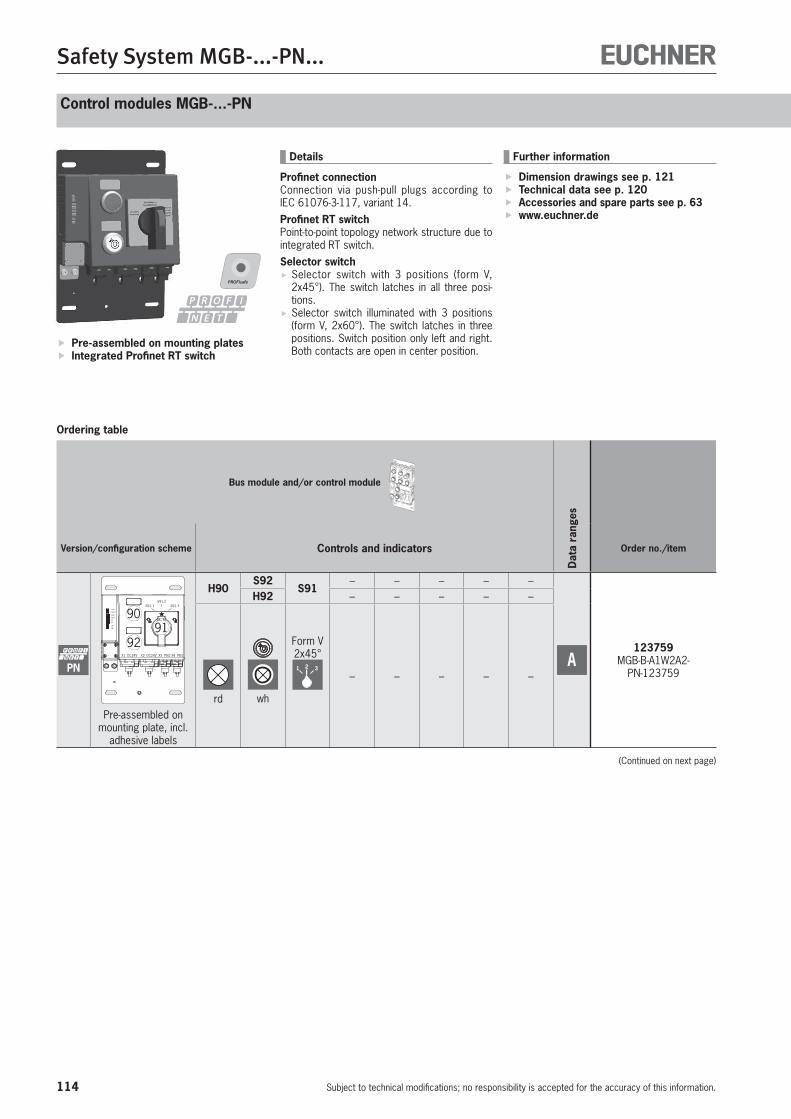
114
Safety System MGB-...-PN...
Subject to technical modifications; no responsibility is accepted for the accuracy of this information.
Control modules MGB-...-PN
Ordering table
Pre-assembled on mounting plates Integrated Profinet RT switch
Details
Profinet connectionConnection via push-pull plugs according to IEC 61076-3-117, variant 14.Profinet RT switchPoint-to-point topology network structure due to integrated RT switch.Selector switch
Selector switch with 3 positions (form V, 2x45°). The switch latches in all three posi-tions.
Selector switch illuminated with 3 positions (form V, 2x60°). The switch latches in three positions. Switch position only left and right. Both contacts are open in center position.
Bus module and/or control module
Dat
a ra
nges
Version/configuration scheme Controls and indicators Order no./item
PN
Link Data
Data Link
SFBF
ONBU
22
11
X4 PN1X3 PN2X2 DC24VX1 DC24V
-S91.1-S91.2
-S91.3
90
9291
Pre-assembled on mounting plate, incl.
adhesive labels
H90S92
S91– – – – –
A123759
MGB-B-A1W2A2-PN-123759
H92 – – – – –
rd wh
Form V2x45°1 2 3
– – – – –
Further information
Dimension drawings see p. 121 Technical data see p. 120 Accessories and spare parts see p. 63 www.euchner.de
(Continued on next page)
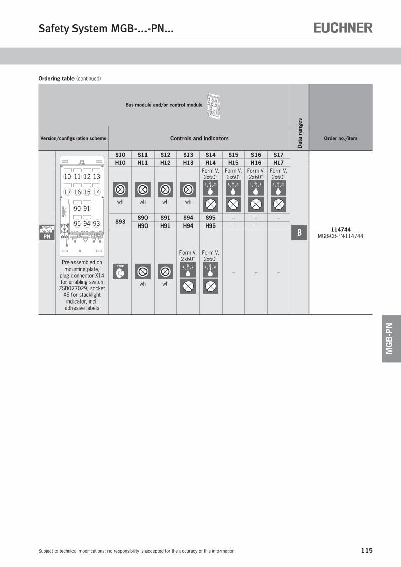
115
Safety System MGB-...-PN...
Subject to technical modifications; no responsibility is accepted for the accuracy of this information.
MG
B-P
N
Ordering table (continued)
Bus module and/or control module
Dat
a ra
nges
Version/configuration scheme Controls and indicators Order no./item
PNX4 PN1X3 PN2X2 DC24VX1 DC24V
Link Data
Data Link
SFBF
ONBU
11
22
1110 12 13
1617 15 14
9495 93
9190
Pre-assembled on mounting plate,
plug connector X14 for enabling switch
ZSB077029, socket X6 for stacklight indicator, incl. adhesive labels
S10 S11 S12 S13 S14 S15 S16 S17
B 114744 MGB-CB-PN-114744
H10 H11 H12 H13 H14 H15 H16 H17
wh wh wh wh
Form V,2x60°1 0 2
Form V,2x60°1 0 2
Form V,2x60°1 0 2
Form V,2x60°1 0 2
S93S90 S91 S94 S95 – – –H90 H91 H94 H95 – – –
STOP
wh wh
Form V,2x60°1 0 2
Form V,2x60°1 0 2
– – –
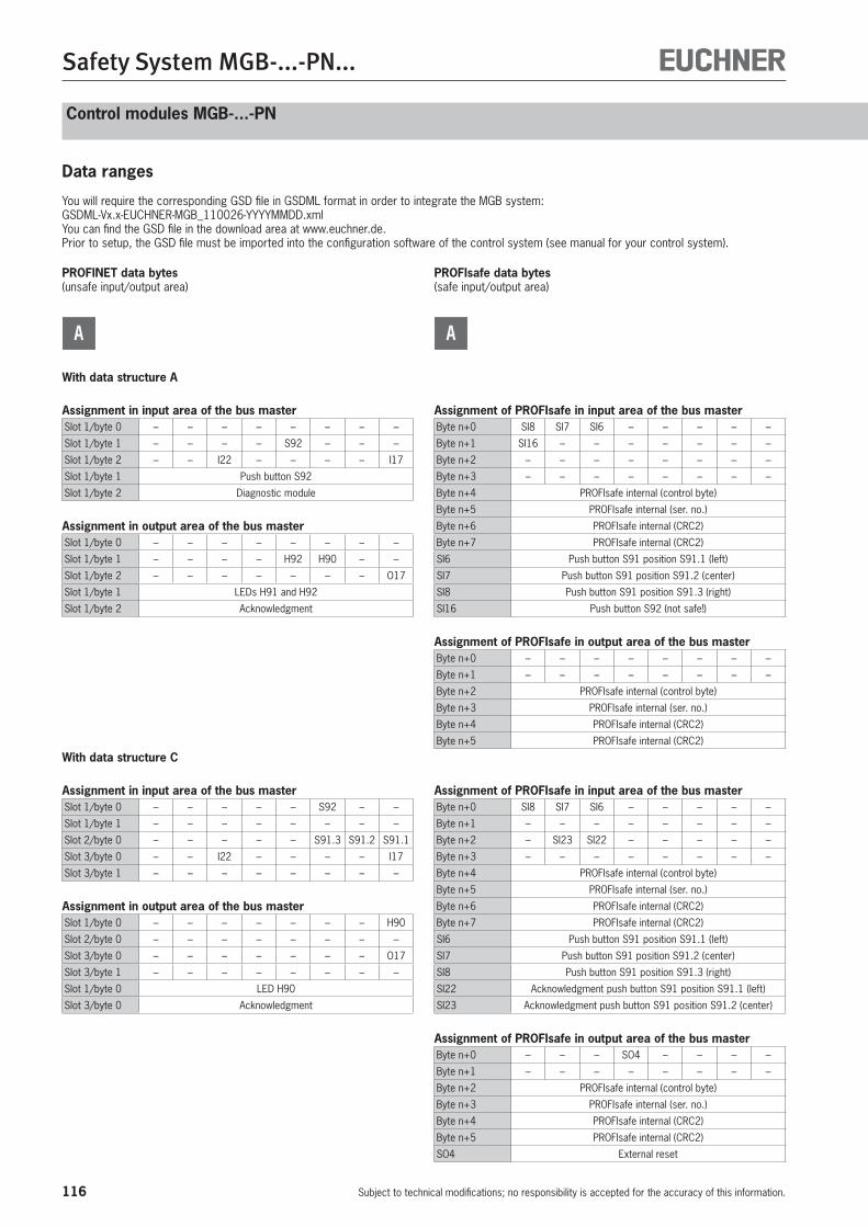
116
Safety System MGB-...-PN...
Subject to technical modifications; no responsibility is accepted for the accuracy of this information.
Control modules MGB-...-PN
Data ranges
You will require the corresponding GSD file in GSDML format in order to integrate the MGB system:GSDML-Vx.x-EUCHNER-MGB_110026-YYYYMMDD.xmlYou can find the GSD file in the download area at www.euchner.de.Prior to setup, the GSD file must be imported into the configuration software of the control system (see manual for your control system).
PROFINET data bytes(unsafe input/output area)
A
With data structure A
Assignment in input area of the bus masterSlot 1/byte 0 – – – – – – – –
Slot 1/byte 1 – – – – S92 – – –
Slot 1/byte 2 – – I22 – – – – I17
Slot 1/byte 1 Push button S92
Slot 1/byte 2 Diagnostic module
Assignment in output area of the bus masterSlot 1/byte 0 – – – – – – – –
Slot 1/byte 1 – – – – H92 H90 – –
Slot 1/byte 2 – – – – – – – O17
Slot 1/byte 1 LEDs H91 and H92
Slot 1/byte 2 Acknowledgment
With data structure C
Assignment in input area of the bus masterSlot 1/byte 0 – – – – – S92 – –
Slot 1/byte 1 – – – – – – – –
Slot 2/byte 0 – – – – – S91.3 S91.2 S91.1
Slot 3/byte 0 – – I22 – – – – I17
Slot 3/byte 1 – – – – – – – –
Assignment in output area of the bus masterSlot 1/byte 0 – – – – – – – H90
Slot 2/byte 0 – – – – – – – –
Slot 3/byte 0 – – – – – – – O17
Slot 3/byte 1 – – – – – – – –
Slot 1/byte 0 LED H90
Slot 3/byte 0 Acknowledgment
PROFIsafe data bytes(safe input/output area)
A
Assignment of PROFIsafe in input area of the bus masterByte n+0 SI8 SI7 SI6 – – – – –
Byte n+1 SI16 – – – – – – –
Byte n+2 – – – – – – – –
Byte n+3 – – – – – – – –
Byte n+4 PROFIsafe internal (control byte)
Byte n+5 PROFIsafe internal (ser. no.)
Byte n+6 PROFIsafe internal (CRC2)
Byte n+7 PROFIsafe internal (CRC2)
SI6 Push button S91 position S91.1 (left)
SI7 Push button S91 position S91.2 (center)
SI8 Push button S91 position S91.3 (right)
SI16 Push button S92 (not safe!)
Assignment of PROFIsafe in output area of the bus masterByte n+0 – – – – – – – –
Byte n+1 – – – – – – – –
Byte n+2 PROFIsafe internal (control byte)
Byte n+3 PROFIsafe internal (ser. no.)
Byte n+4 PROFIsafe internal (CRC2)
Byte n+5 PROFIsafe internal (CRC2)
Assignment of PROFIsafe in input area of the bus masterByte n+0 SI8 SI7 SI6 – – – – –
Byte n+1 – – – – – – – –
Byte n+2 – SI23 SI22 – – – – –
Byte n+3 – – – – – – – –
Byte n+4 PROFIsafe internal (control byte)
Byte n+5 PROFIsafe internal (ser. no.)
Byte n+6 PROFIsafe internal (CRC2)
Byte n+7 PROFIsafe internal (CRC2)
SI6 Push button S91 position S91.1 (left)
SI7 Push button S91 position S91.2 (center)
SI8 Push button S91 position S91.3 (right)
SI22 Acknowledgment push button S91 position S91.1 (left)
SI23 Acknowledgment push button S91 position S91.2 (center)
Assignment of PROFIsafe in output area of the bus masterByte n+0 – – – SO4 – – – –
Byte n+1 – – – – – – – –
Byte n+2 PROFIsafe internal (control byte)
Byte n+3 PROFIsafe internal (ser. no.)
Byte n+4 PROFIsafe internal (CRC2)
Byte n+5 PROFIsafe internal (CRC2)
SO4 External reset

117
Safety System MGB-...-PN...
Subject to technical modifications; no responsibility is accepted for the accuracy of this information.
MG
B-P
N
PROFINET data bytes(unsafe input/output area)
B
Assignment in input area of the bus masterSlot 1/byte 0 – – S95.1 S94.1 – – S91.1 S90.1
Slot 1/byte 1 – – S95.2 S94.2 – – – –
Slot 2/byte 0 S17.1 S16.1 S15.1 S14.1 S13.1 S12.1 S11.1 S10.1
Slot 2/byte 1 S17.2 S16.2 S15.2 S14.2 – – – –
Slot 4/byte 1 – – – – – – – S93
Slot 5/byte 0 + & – ZT – ZT + – – – – ZTM
Slot 6/byte 0 – – – – I20 I19 – I17
Slot 1/byte 0 Push button S90 - S91 and S94 - S95 1st contact
Slot 1/byte 1 Push button S94 - S95 2nd contact
Slot 2/byte 0 Push button S10 - S17 1st contact
Slot 2/byte 1 Push button S10 - S17 2nd contact
Slot 4/byte 0 Emergency stop monitoring contact (NHM)
Slot 5/byte 0 Enabling switch +/– and monitoring contact (ZTM)
Slot 6/byte 0 Diagnostic module
Assignment in output area of the bus masterSlot 1/byte 0 – – H95 H94 – – H91 H90
Slot 2/byte 0 H17 H16 H15 H14 H13 H12 H11 H10
Slot 3/byte 0 – – – O21 O20 O19 O18 O17
Slot 4/byte 1 – – – – – – – –
Slot 5/byte 0 – – – – – – ZT – ZT +
Slot 6/byte 0 – – – – – – – O17
Slot 1/byte 0 LEDs H90 - H95
Slot 2/byte 0 LEDs H10 - H17
Slot 3/byte 0 Stacklight module O17 - O21
Slot 4/byte 0 LED for possible emergency stop (not used)
Slot 5/byte 0 Enabling switch LEDs +/– (ZT)
Slot 6/byte 0 Diagnostic module
PROFIsafe data bytes(safe input/output area)
B
Assignment of PROFIsafe in input area of the bus masterByte n+0 – – – – – – SI2 SI1
Byte n+1 – – – – – – – –
Byte n+2 PROFIsafe internal (control byte)
Byte n+3 PROFIsafe internal (ser. no.)
Byte n+4 PROFIsafe internal (CRC2)
Byte n+5 PROFIsafe internal (CRC2)
SI1 Emergency stop S93
SI2 Enabling switch X14
Assignment of PROFIsafe in output area of the bus masterByte n+0 – – – – – – – –
Byte n+1 – – – – – – – –
Byte n+2 PROFIsafe internal (control byte)
Byte n+3 PROFIsafe internal (ser. no.)
Byte n+4 PROFIsafe internal (CRC2)
Byte n+5 PROFIsafe internal (CRC2)
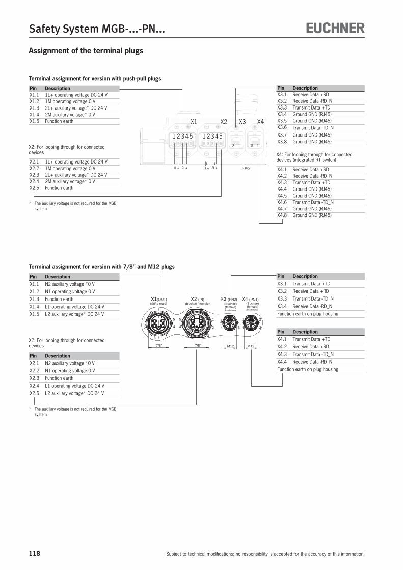
118
Safety System MGB-...-PN...
Subject to technical modifications; no responsibility is accepted for the accuracy of this information.
Terminal assignment for version with push-pull plugs
X1 X2 X3 X4
12345 18 1 8 1
2345
1L+ 2L+ 1L+ 2L+ RJ45
Pin DescriptionX3.1 Receive Data +RDX3.2 Receive Data -RD_NX3.3 Transmit Data +TDX3.4 Ground GND (RJ45)X3.5 Ground GND (RJ45)X3.6 Transmit Data -TD_N X3.7 Ground GND (RJ45)X3.8 Ground GND (RJ45)
X4: For looping through for connected devices (integrated RT switch)
X4.1 Receive Data +RDX4.2 Receive Data -RD_NX4.3 Transmit Data +TDX4.4 Ground GND (RJ45)X4.5 Ground GND (RJ45)X4.6 Transmit Data -TD_N X4.7 Ground GND (RJ45)X4.8 Ground GND (RJ45)
Pin DescriptionX1.1 1L+ operating voltage DC 24 VX1.2 1M operating voltage 0 VX1.3 2L+ auxiliary voltage* DC 24 VX1.4 2M auxiliary voltage* 0 VX1.5 Function earth
X2: For looping through for connected devices
X2.1 1L+ operating voltage DC 24 VX2.2 1M operating voltage 0 VX2.3 2L+ auxiliary voltage* DC 24 VX2.4 2M auxiliary voltage* 0 VX2.5 Function earth
* The auxiliary voltage is not required for the MGB system
Assignment of the terminal plugs
Terminal assignment for version with 7/8" and M12 plugs
1
4
1 2
3
d-kodierung(female)(Buchse)
3
X1(OUT)(Stift / male)
X2 (IN)(Buchse / female)
X3 (PN2)
d-kodierung
2
3
4
5 5
4
3
1
2
1
4
X4 (PN1)(Buchse)(female)
2
M127/8" M127/8"
Pin DescriptionX1.1 N2 auxiliary voltage *0 V
X1.2 N1 operating voltage 0 V
X1.3 Function earth
X1.4 L1 operating voltage DC 24 V
X1.5 L2 auxiliary voltage* DC 24 V
X2: For looping through for connected devices
Pin DescriptionX2.1 N2 auxiliary voltage *0 V
X2.2 N1 operating voltage 0 V
X2.3 Function earth
X2.4 L1 operating voltage DC 24 V
X2.5 L2 auxiliary voltage* DC 24 V
* The auxiliary voltage is not required for the MGB system
Pin DescriptionX3.1 Transmit Data +TD
X3.2 Receive Data +RD
X3.3 Transmit Data -TD_N
X3.4 Receive Data -RD_N
Function earth on plug housing
Pin DescriptionX4.1 Transmit Data +TD
X4.2 Receive Data +RD
X4.3 Transmit Data -TD_N
X4.4 Receive Data -RD_N
Function earth on plug housing
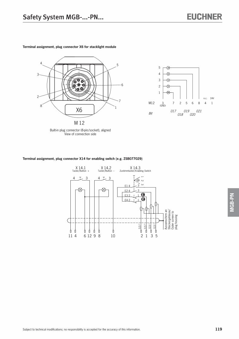
119
Safety System MGB-...-PN...
Subject to technical modifications; no responsibility is accepted for the accuracy of this information.
MG
B-P
N
Terminal assignment, plug connector X6 for stacklight module
(GND)
n.c. 24V
020021019
018017
1
Bit
M12 42 8657
1
2
3
4
5
3
M 12
2
3
4 5
6
7
18
X6
Built-in plug connector (8-pin/socket), alignedView of connection side
Terminal assignment, plug connector X14 for enabling switch (e.g. ZSB077029)0,
5 ²
0,5
²
0,5
²
0,5
²
5319 86 12411 10 2
X 14.1Taster/Button +
Auss
ensc
hirm
an
Stec
kerg
ehäu
se/
Out
er s
cree
n to
pl
ug h
ousi
ng4 3 34
X 14.2Taster/Button –
E1 4
E2 4
E3 2
E4 2
1 2 3
1
1
X 14.3Zustimmtaster/Enabling Switch
3
3
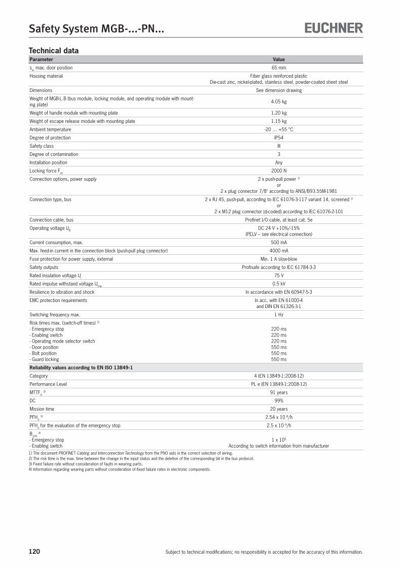
120
Safety System MGB-...-PN...
Subject to technical modifications; no responsibility is accepted for the accuracy of this information.
Parameter Value
sar max. door position 65 mm
Housing material Fiber glass reinforced plasticDie-cast zinc, nickel-plated, stainless steel, powder-coated sheet steel
Dimensions See dimension drawing
Weight of MGB-L.B (bus module, locking module, and operating module with mount-ing plate)
4.05 kg
Weight of handle module with mounting plate 1.20 kg
Weight of escape release module with mounting plate 1.15 kg
Ambient temperature -20 … +55 °C
Degree of protection IP54
Safety class III
Degree of contamination 3
Installation position Any
Locking force Fzh 2000 N
Connection options, power supply 2 x push-pull power 1) or
2 x plug connector 7/8" according to ANSI/B93.55M-1981
Connection type, bus 2 x RJ 45, push-pull, according to IEC 61076-3-117 variant 14, screened 1) or
2 x M12 plug connector (d-coded) according to IEC 61076-2-101
Connection cable, bus Profinet I/O cable, at least cat. 5e
Operating voltage UB DC 24 V +10%/-15%(PELV – see electrical connection)
Current consumption, max. 500 mA
Max. feed-in current in the connection block (push-pull plug connector) 4000 mA
Fuse protection for power supply, external Min. 1 A slow-blow
Safety outputs Profisafe according to IEC 61784-3-3
Rated insulation voltage Ui 75 V
Rated impulse withstand voltage Uimp 0.5 kV
Resilience to vibration and shock In accordance with EN 60947-5-3
EMC protection requirements In acc. with EN 61000-4 and DIN EN 61326-3-1
Switching frequency max. 1 Hz
Risk times max. (switch-off times) 2)
- Emergency stop- Enabling switch- Operating mode selector switch- Door position- Bolt position- Guard locking
220 ms220 ms220 ms550 ms550 ms550 ms
Reliability values according to EN ISO 13849-1
Category 4 (EN 13849-1:2008-12)
Performance Level PL e (EN 13849-1:2008-12)
MTTFd 3) 91 years
DC 99%
Mission time 20 years
PFHd 3) 2.54 x 10 -8/h
PFHd for the evaluation of the emergency stop 2.5 x 10 -8/h
B10d 4)
- Emergency stop- Enabling switch
1 x 10⁵ According to switch information from manufacturer
1) The document PROFINET Cabling and Interconnection Technology from the PNO aids in the correct selection of wiring.2) The risk time is the max. time between the change in the input status and the deletion of the corresponding bit in the bus protocol.3) Fixed failure rate without consideration of faults in wearing parts.4) Information regarding wearing parts without consideration of fixed failure rates in electronic components.
Technical data
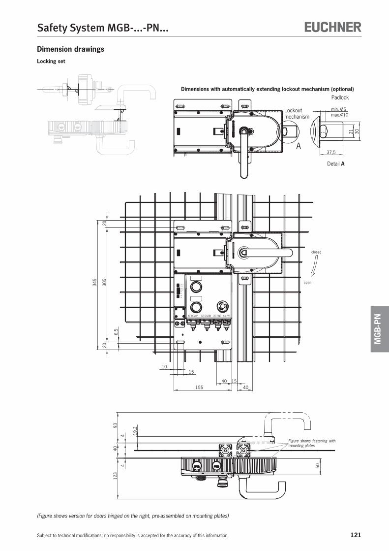
121
Safety System MGB-...-PN...
Subject to technical modifications; no responsibility is accepted for the accuracy of this information.
MG
B-P
NV42CD1X 1NP4XV42CD2X 2NP3X
SFBF
ON
BU
11
2
LinkData
DataLink
2
9340
4 19,2
504
123
closed
open
15
305
1540
20
155
20
6,5
40
10
345
min. 6
37,5
max. 10
3021
A
Figure shows fastening with mounting plates
(Figure shows version for doors hinged on the right, pre-assembled on mounting plates)
Dimension drawingsLocking set
Dimensions with automatically extending lockout mechanism (optional)
Detail A
Padlock
Lockout mechanism
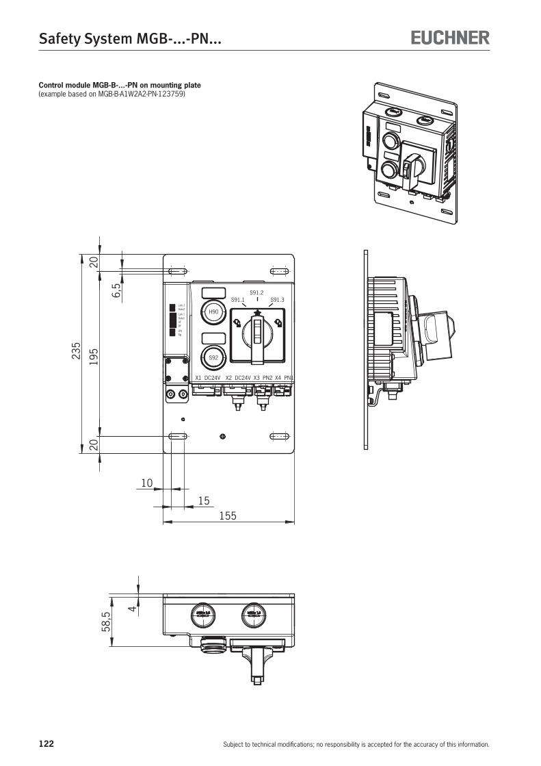
122
Safety System MGB-...-PN...
Subject to technical modifications; no responsibility is accepted for the accuracy of this information.
Control module MGB-B-...-PN on mounting plate(example based on MGB-B-A1W2A2-PN-123759)
155
235
15
10
2019
520
6,5
Link Data
Data Link
SFBF
ONBU
22
11
X4 PN1X3 PN2X2 DC24VX1 DC24V
S91.1S91.2
S91.3
H90
S92
4
58,5
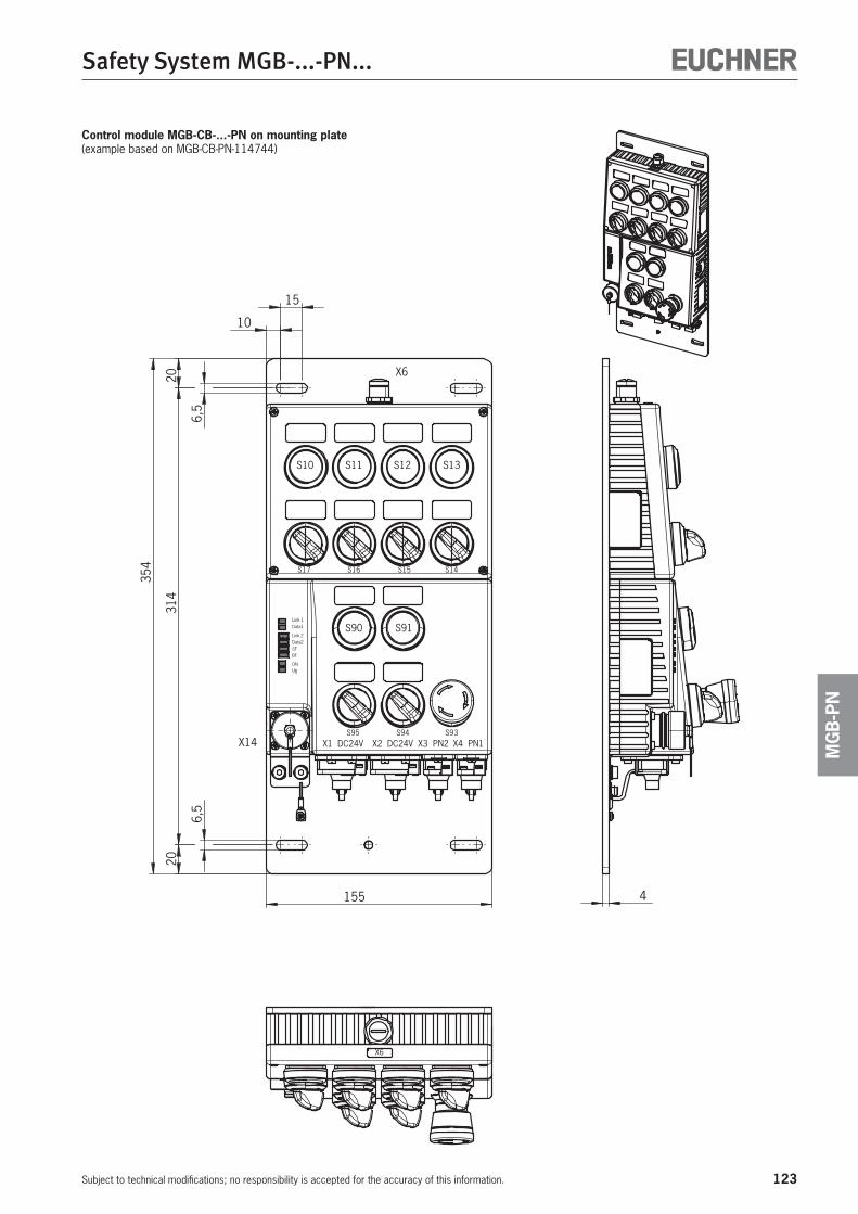
123
Safety System MGB-...-PN...
Subject to technical modifications; no responsibility is accepted for the accuracy of this information.
MG
B-P
N
Control module MGB-CB-...-PN on mounting plate(example based on MGB-CB-PN-114744)
4
X6
354
2031
420
6,5
6,5
10
15
155
X6
S17 S16 S15 S14
S13S12S11S10
X4 PN1X3 PN2X2 DC24VX1 DC24V
Link Data
Data Link
SFBF
ONBU
11
22
S93S94
S91
S95
S90
X14
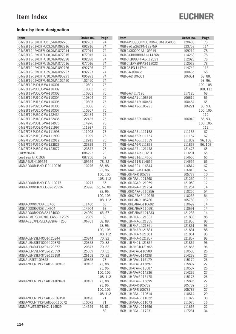
Item Index
Item Order no. Page Item Order no. Page
124
Index by item designation
C-M23F19-19XDIFPU01,5-MA-092761 092761 74C-M23F19-19XDIFPU03,0-MA-092816 092816 74C-M23F19-19XDIFPU06,0-MA-077014 077014 74C-M23F19-19XDIFPU08,0-MA-077015 077015 74C-M23F19-19XDIFPU10,0-MA-092898 092898 74C-M23F19-19XDIFPU15,0-MA-077016 077016 74C-M23F19-19XDIFPU20,0-MA-092726 092726 74C-M23F19-19XDIFPU25,0-MA-092727 092727 74C-M23F19-19XDIFPU30,0-MA-095993 095993 74C-M23F19-19XDIFPU40,0-MA-102490 102490 74C-M23F19-PU01,5-MA-110301 110301 75C-M23F19-PU03,0-MA-110302 110302 75C-M23F19-PU06,0-MA-110303 110303 75C-M23F19-PU10,0-MA-110304 110304 75C-M23F19-PU15,0-MA-110305 110305 75C-M23F19-PU20,0-MA-110306 110306 75C-M23F19-PU25,0-MA-110307 110307 75C-M23F19-PU30,0-MA-122434 122434 75C-M23F19-PU40,0-MA-122435 122435 75C-M27F26-PU01,1-MA-114976 114976 76C-M27F26-PU02,0-MA-111997 111997 76C-M27F26-PU05,0-MA-111998 111998 76C-M27F26-PU10,0-MA-111999 111999 76C-M27F26-PU20,0-MA-112912 112912 76C-M27F26-PU35,0-MA-123829 123829 76C-M27F26-PU50,0-MA-123877 123877 76EKPM20/06 086223 73Lead seal kit C1937 087256 69MGB-A-BUSH-109524 109524 78, 82MGB-A-DOORHANDLE-R-110276 110276 68, 88, 93, 96, 100, 105, 108, 112MGB-A-DOORHANDLE-S-110277 110277 65MGB-A-DOORHANDLE-S2-123926 123926 65, 67, 88, 93, 96, 100, 105, 108, 112MGB-A-DOORKNOB-111460 111460 65MGB-A-DOORKNOB-114904 114904 68MGB-A-DOORKNOB-S2-124030 124030 65, 67MGB-A-EMERGENCYRELEASE-112989 112989 69MGB-A-ESCAPERELEASESHAFT 250 106761 68, 88, 93, 96, 100, 105, 108, 112MGB-A-LENSSET-0001-120344 120344 70, 82MGB-A-LENSSET-0002-120378 120378 70, 82MGB-A-LENSSET-SY01-120377 120377 70, 82MGB-A-LENSSET-SY02-125359 125359 70, 82MGB-A-LENSSET-SY03-126158 126158 70, 82MGB-A-LPSET-109858 109858 78MGB-A-MOUNTINGPLATE-E-109492 109492 71, 88, 93, 96, 100, 105, 108, 112MGB-A-MOUNTINGPLATE-H-109491 109491 71, 88, 93, 96, 100, 105, 108, 112MGB-A-MOUNTINGPLATE-L-109490 109490 71MGB-A-MOUNTINGPLATE-LC-110072 110072 71MGB-A-PLATESET-NN01-114529 114529 69, 81, 82
MGB-A-PLUGCONNECTOR-RC18-1204035 120403 73MGB-B-A1W2A2-PN-123759 123759 114MGB-C-000000-A1-109219 109219 78MGB-C-0HHHHHH-A1-114268 114268 78MGB-C-1BBBBPP-A3-112023 112023 78MGB-C-1EPPBPP-A3-112022 112022 78MGB-CB-PN-114744 114744 115MGB-E-A-100465 100465 68MGB-E-A2-106051 106051 68, 88, 93, 96, 100, 105, 108, 112MGB-E-A7-117126 117126 68MGB-H-AA1A1-L-106619 106619 65MGB-H-AA1A1-R-100464 100464 65MGB-H-AA1A2-L-106221 106221 88, 93, 100, 105, 112MGB-H-AA1A2-R-106049 106049 88, 93, 100, 105, 112MGB-H-AA1A3-L-111158 111158 67MGB-H-AA1A3-R-111157 111157 67MGB-H-AA1A6-L-111839 111839 96, 108MGB-H-AA1A6-R-111838 111838 96, 108MGB-H-AA1A7-L-121478 121478 65MGB-H-AA1A7-R-113201 113201 65MGB-H-AA1B1-L-114656 114656 65MGB-H-AA1B1-R-114655 114655 65MGB-H-AA1B2-L-116814 116814 67MGB-H-AA1B2-R-116813 116813 67MGB-L0H-AR-R-105778 105778 10MGB-L0H-ARA-L-121260 121260 14MGB-L0H-ARA-R-121059 121059 12MGB-L0H-ARA-R-121254 121254 14MGB-L0HC-ARA-L-110256 110256 54MGB-L0HC-ARA-R-110255 110255 54MGB-L0HE-AR-R-105780 105780 10MGB-L0HE-ARA-L-110692 110692 14MGB-L0HE-ARA-R-110691 110691 14MGB-L0HE-ARA-R-121233 121233 14MGB-L1B-PNA-L-121833 121833 88MGB-L1B-PNA-L-121855 121855 93MGB-L1B-PNA-L-121861 121861 93MGB-L1B-PNA-R-121831 121831 88MGB-L1B-PNA-R-121851 121851 93MGB-L1B-PNA-R-121857 121857 93MGB-L1B-PNC-L-121867 121867 96MGB-L1B-PNC-R-121865 121865 96MGB-L1H-APA-L-110588 110588 26MGB-L1H-APA-L-114238 114238 27MGB-L1H-APA-L-115179 115179 26MGB-L1H-APA-L-115897 115897 27MGB-L1H-APA-R-110587 110587 26MGB-L1H-APA-R-114236 114236 27MGB-L1H-APA-R-115178 115178 26MGB-L1H-APA-R-115895 115895 27MGB-L1H-AR-R-105782 105782 16MGB-L1H-AR-R-105783 105783 27MGB-L1H-ARA-L-110614 110614 29MGB-L1H-ARA-L-111022 111022 30MGB-L1H-ARA-L-111073 111073 16MGB-L1H-ARA-L-111656 111656 22MGB-L1H-ARA-L-117231 117231 34
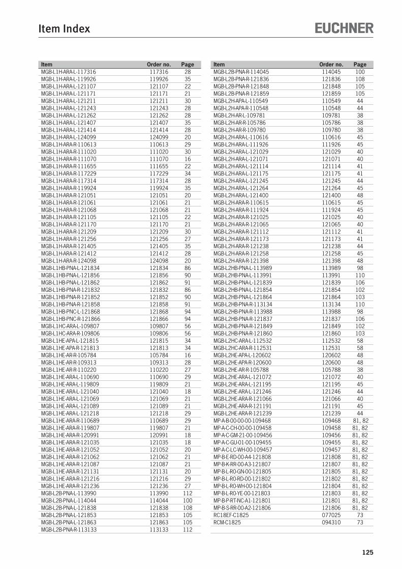
Item Index
Item Order no. Page Item Order no. Page
125
MGB-L1H-ARA-L-117316 117316 28MGB-L1H-ARA-L-119926 119926 35MGB-L1H-ARA-L-121107 121107 22MGB-L1H-ARA-L-121171 121171 21MGB-L1H-ARA-L-121211 121211 30MGB-L1H-ARA-L-121243 121243 28MGB-L1H-ARA-L-121262 121262 28MGB-L1H-ARA-L-121407 121407 35MGB-L1H-ARA-L-121414 121414 28MGB-L1H-ARA-L-124099 124099 20MGB-L1H-ARA-R-110613 110613 29MGB-L1H-ARA-R-111020 111020 30MGB-L1H-ARA-R-111070 111070 16MGB-L1H-ARA-R-111655 111655 22MGB-L1H-ARA-R-117229 117229 34MGB-L1H-ARA-R-117314 117314 28MGB-L1H-ARA-R-119924 119924 35MGB-L1H-ARA-R-121051 121051 20MGB-L1H-ARA-R-121061 121061 21MGB-L1H-ARA-R-121068 121068 21MGB-L1H-ARA-R-121105 121105 22MGB-L1H-ARA-R-121170 121170 21MGB-L1H-ARA-R-121209 121209 30MGB-L1H-ARA-R-121256 121256 27MGB-L1H-ARA-R-121405 121405 35MGB-L1H-ARA-R-121412 121412 28MGB-L1H-ARA-R-124098 124098 20MGB-L1HB-PNA-L-121834 121834 86MGB-L1HB-PNA-L-121856 121856 90MGB-L1HB-PNA-L-121862 121862 91MGB-L1HB-PNA-R-121832 121832 86MGB-L1HB-PNA-R-121852 121852 90MGB-L1HB-PNA-R-121858 121858 91MGB-L1HB-PNC-L-121868 121868 94MGB-L1HB-PNC-R-121866 121866 94MGB-L1HC-ARA-L-109807 109807 56MGB-L1HC-ARA-R-109806 109806 56MGB-L1HE-APA-L-121815 121815 34MGB-L1HE-APA-R-121813 121813 34MGB-L1HE-AR-R-105784 105784 16MGB-L1HE-AR-R-109313 109313 28MGB-L1HE-AR-R-110220 110220 27MGB-L1HE-ARA-L-110690 110690 29MGB-L1HE-ARA-L-119809 119809 21MGB-L1HE-ARA-L-121040 121040 18MGB-L1HE-ARA-L-121069 121069 21MGB-L1HE-ARA-L-121089 121089 21MGB-L1HE-ARA-L-121218 121218 29MGB-L1HE-ARA-R-110689 110689 29MGB-L1HE-ARA-R-119807 119807 21MGB-L1HE-ARA-R-120991 120991 18MGB-L1HE-ARA-R-121035 121035 18MGB-L1HE-ARA-R-121052 121052 20MGB-L1HE-ARA-R-121062 121062 21MGB-L1HE-ARA-R-121087 121087 21MGB-L1HE-ARA-R-121131 121131 20MGB-L1HE-ARA-R-121216 121216 29MGB-L1HE-ARA-R-121236 121236 27MGB-L2B-PNA-L-113990 113990 112MGB-L2B-PNA-L-114044 114044 100MGB-L2B-PNA-L-121838 121838 108MGB-L2B-PNA-L-121853 121853 105MGB-L2B-PNA-L-121863 121863 105MGB-L2B-PNA-R-113133 113133 112
MGB-L2B-PNA-R-114045 114045 100MGB-L2B-PNA-R-121836 121836 108MGB-L2B-PNA-R-121848 121848 105MGB-L2B-PNA-R-121859 121859 105MGB-L2H-APA-L-110549 110549 44MGB-L2H-APA-R-110548 110548 44MGB-L2H-AR-L-109781 109781 38MGB-L2H-AR-R-105786 105786 38MGB-L2H-AR-R-109780 109780 38MGB-L2H-ARA-L-110616 110616 45MGB-L2H-ARA-L-111926 111926 45MGB-L2H-ARA-L-121029 121029 40MGB-L2H-ARA-L-121071 121071 40MGB-L2H-ARA-L-121114 121114 41MGB-L2H-ARA-L-121175 121175 41MGB-L2H-ARA-L-121245 121245 44MGB-L2H-ARA-L-121264 121264 45MGB-L2H-ARA-L-121400 121400 48MGB-L2H-ARA-R-110615 110615 45MGB-L2H-ARA-R-111924 111924 45MGB-L2H-ARA-R-121025 121025 40MGB-L2H-ARA-R-121065 121065 40MGB-L2H-ARA-R-121112 121112 41MGB-L2H-ARA-R-121173 121173 41MGB-L2H-ARA-R-121238 121238 44MGB-L2H-ARA-R-121258 121258 45MGB-L2H-ARA-R-121398 121398 48MGB-L2HB-PNA-L-113989 113989 98MGB-L2HB-PNA-L-113991 113991 110MGB-L2HB-PNA-L-121839 121839 106MGB-L2HB-PNA-L-121854 121854 102MGB-L2HB-PNA-L-121864 121864 103MGB-L2HB-PNA-R-113134 113134 110MGB-L2HB-PNA-R-113988 113988 98MGB-L2HB-PNA-R-121837 121837 106MGB-L2HB-PNA-R-121849 121849 102MGB-L2HB-PNA-R-121860 121860 103MGB-L2HC-ARA-L-112532 112532 58MGB-L2HC-ARA-R-112531 112531 58MGB-L2HE-APA-L-120602 120602 48MGB-L2HE-APA-R-120600 120600 48MGB-L2HE-AR-R-105788 105788 38MGB-L2HE-ARA-L-121072 121072 40MGB-L2HE-ARA-L-121195 121195 45MGB-L2HE-ARA-L-121246 121246 44MGB-L2HE-ARA-R-121066 121066 40MGB-L2HE-ARA-R-121191 121191 45MGB-L2HE-ARA-R-121239 121239 44MP-A-B-00-00-00-109468 109468 81, 82MP-A-C-CH-00-00-109458 109458 81, 82MP-A-C-GM-21-00-109456 109456 81, 82MP-A-C-GU-01-00-109455 109455 81, 82MP-A-C-LC-WH-00-109457 109457 81, 82MP-B-E-RD-00-A4-121808 121808 81, 82MP-B-K-RR-00-A3-121807 121807 81, 82MP-B-L-R0-GN-00-121805 121805 81, 82MP-B-L-R0-RD-00-121802 121802 81, 82MP-B-L-R0-WH-00-121804 121804 81, 82MP-B-L-R0-YE-00-121803 121803 81, 82MP-B-P-RT-NC-A1-121801 121801 81, 82MP-B-S-RR-00-A2-121806 121806 81, 82RC18EF-C1825 077025 73RCM-C1825 094310 73
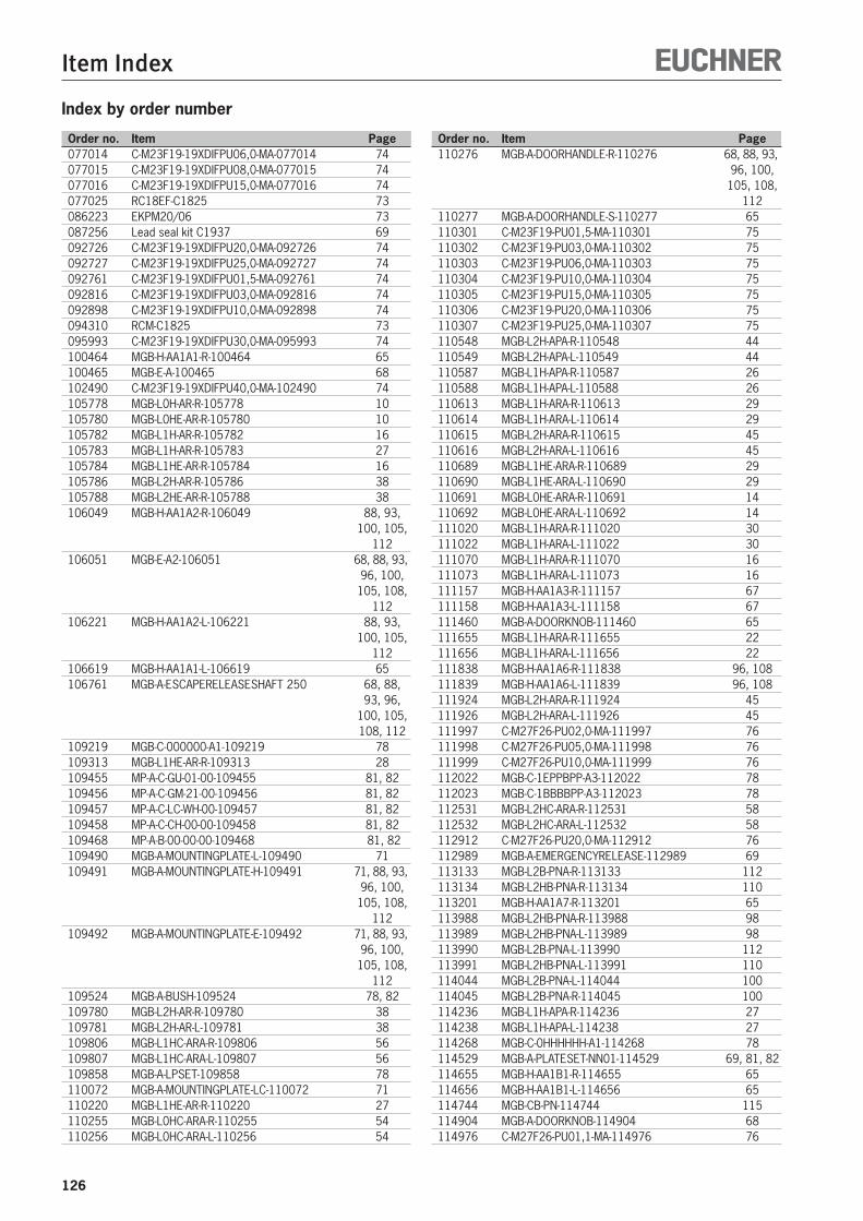
Item Index
Order no. Item Page Order no. Item Page
126
Index by order number
077014 C-M23F19-19XDIFPU06,0-MA-077014 74077015 C-M23F19-19XDIFPU08,0-MA-077015 74077016 C-M23F19-19XDIFPU15,0-MA-077016 74077025 RC18EF-C1825 73086223 EKPM20/06 73087256 Lead seal kit C1937 69092726 C-M23F19-19XDIFPU20,0-MA-092726 74092727 C-M23F19-19XDIFPU25,0-MA-092727 74092761 C-M23F19-19XDIFPU01,5-MA-092761 74092816 C-M23F19-19XDIFPU03,0-MA-092816 74092898 C-M23F19-19XDIFPU10,0-MA-092898 74094310 RCM-C1825 73095993 C-M23F19-19XDIFPU30,0-MA-095993 74100464 MGB-H-AA1A1-R-100464 65100465 MGB-E-A-100465 68102490 C-M23F19-19XDIFPU40,0-MA-102490 74105778 MGB-L0H-AR-R-105778 10105780 MGB-L0HE-AR-R-105780 10105782 MGB-L1H-AR-R-105782 16105783 MGB-L1H-AR-R-105783 27105784 MGB-L1HE-AR-R-105784 16105786 MGB-L2H-AR-R-105786 38105788 MGB-L2HE-AR-R-105788 38106049 MGB-H-AA1A2-R-106049 88, 93, 100, 105, 112106051 MGB-E-A2-106051 68, 88, 93, 96, 100, 105, 108, 112106221 MGB-H-AA1A2-L-106221 88, 93, 100, 105, 112106619 MGB-H-AA1A1-L-106619 65106761 MGB-A-ESCAPERELEASESHAFT 250 68, 88, 93, 96, 100, 105, 108, 112109219 MGB-C-000000-A1-109219 78109313 MGB-L1HE-AR-R-109313 28109455 MP-A-C-GU-01-00-109455 81, 82109456 MP-A-C-GM-21-00-109456 81, 82109457 MP-A-C-LC-WH-00-109457 81, 82109458 MP-A-C-CH-00-00-109458 81, 82109468 MP-A-B-00-00-00-109468 81, 82109490 MGB-A-MOUNTINGPLATE-L-109490 71109491 MGB-A-MOUNTINGPLATE-H-109491 71, 88, 93, 96, 100, 105, 108, 112109492 MGB-A-MOUNTINGPLATE-E-109492 71, 88, 93, 96, 100, 105, 108, 112109524 MGB-A-BUSH-109524 78, 82109780 MGB-L2H-AR-R-109780 38109781 MGB-L2H-AR-L-109781 38109806 MGB-L1HC-ARA-R-109806 56109807 MGB-L1HC-ARA-L-109807 56109858 MGB-A-LPSET-109858 78110072 MGB-A-MOUNTINGPLATE-LC-110072 71110220 MGB-L1HE-AR-R-110220 27110255 MGB-L0HC-ARA-R-110255 54110256 MGB-L0HC-ARA-L-110256 54
110276 MGB-A-DOORHANDLE-R-110276 68, 88, 93, 96, 100, 105, 108, 112110277 MGB-A-DOORHANDLE-S-110277 65110301 C-M23F19-PU01,5-MA-110301 75110302 C-M23F19-PU03,0-MA-110302 75110303 C-M23F19-PU06,0-MA-110303 75110304 C-M23F19-PU10,0-MA-110304 75110305 C-M23F19-PU15,0-MA-110305 75110306 C-M23F19-PU20,0-MA-110306 75110307 C-M23F19-PU25,0-MA-110307 75110548 MGB-L2H-APA-R-110548 44110549 MGB-L2H-APA-L-110549 44110587 MGB-L1H-APA-R-110587 26110588 MGB-L1H-APA-L-110588 26110613 MGB-L1H-ARA-R-110613 29110614 MGB-L1H-ARA-L-110614 29110615 MGB-L2H-ARA-R-110615 45110616 MGB-L2H-ARA-L-110616 45110689 MGB-L1HE-ARA-R-110689 29110690 MGB-L1HE-ARA-L-110690 29110691 MGB-L0HE-ARA-R-110691 14110692 MGB-L0HE-ARA-L-110692 14111020 MGB-L1H-ARA-R-111020 30111022 MGB-L1H-ARA-L-111022 30111070 MGB-L1H-ARA-R-111070 16111073 MGB-L1H-ARA-L-111073 16111157 MGB-H-AA1A3-R-111157 67111158 MGB-H-AA1A3-L-111158 67111460 MGB-A-DOORKNOB-111460 65111655 MGB-L1H-ARA-R-111655 22111656 MGB-L1H-ARA-L-111656 22111838 MGB-H-AA1A6-R-111838 96, 108111839 MGB-H-AA1A6-L-111839 96, 108111924 MGB-L2H-ARA-R-111924 45111926 MGB-L2H-ARA-L-111926 45111997 C-M27F26-PU02,0-MA-111997 76111998 C-M27F26-PU05,0-MA-111998 76111999 C-M27F26-PU10,0-MA-111999 76112022 MGB-C-1EPPBPP-A3-112022 78112023 MGB-C-1BBBBPP-A3-112023 78112531 MGB-L2HC-ARA-R-112531 58112532 MGB-L2HC-ARA-L-112532 58112912 C-M27F26-PU20,0-MA-112912 76112989 MGB-A-EMERGENCYRELEASE-112989 69113133 MGB-L2B-PNA-R-113133 112113134 MGB-L2HB-PNA-R-113134 110113201 MGB-H-AA1A7-R-113201 65113988 MGB-L2HB-PNA-R-113988 98113989 MGB-L2HB-PNA-L-113989 98113990 MGB-L2B-PNA-L-113990 112113991 MGB-L2HB-PNA-L-113991 110114044 MGB-L2B-PNA-L-114044 100114045 MGB-L2B-PNA-R-114045 100114236 MGB-L1H-APA-R-114236 27114238 MGB-L1H-APA-L-114238 27114268 MGB-C-0HHHHHH-A1-114268 78114529 MGB-A-PLATESET-NN01-114529 69, 81, 82114655 MGB-H-AA1B1-R-114655 65114656 MGB-H-AA1B1-L-114656 65114744 MGB-CB-PN-114744 115114904 MGB-A-DOORKNOB-114904 68114976 C-M27F26-PU01,1-MA-114976 76
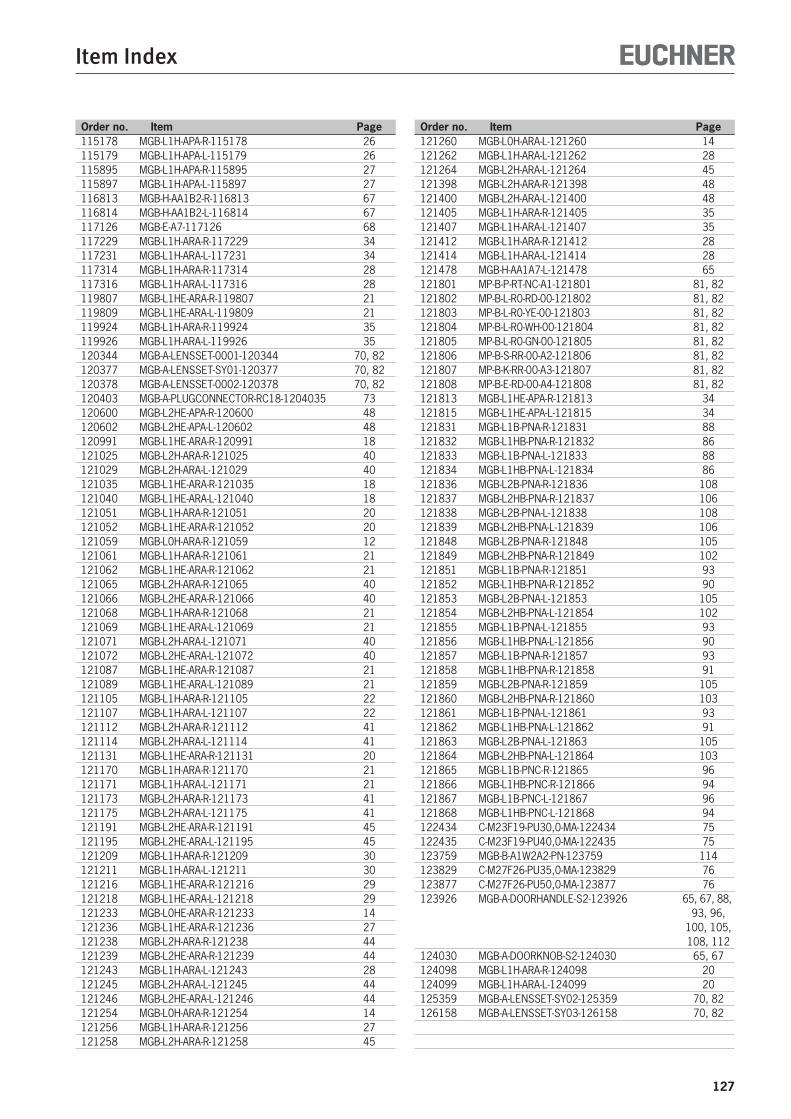
Item Index
Order no. Item Page Order no. Item Page
127
115178 MGB-L1H-APA-R-115178 26115179 MGB-L1H-APA-L-115179 26115895 MGB-L1H-APA-R-115895 27115897 MGB-L1H-APA-L-115897 27116813 MGB-H-AA1B2-R-116813 67116814 MGB-H-AA1B2-L-116814 67117126 MGB-E-A7-117126 68117229 MGB-L1H-ARA-R-117229 34117231 MGB-L1H-ARA-L-117231 34117314 MGB-L1H-ARA-R-117314 28117316 MGB-L1H-ARA-L-117316 28119807 MGB-L1HE-ARA-R-119807 21119809 MGB-L1HE-ARA-L-119809 21119924 MGB-L1H-ARA-R-119924 35119926 MGB-L1H-ARA-L-119926 35120344 MGB-A-LENSSET-0001-120344 70, 82120377 MGB-A-LENSSET-SY01-120377 70, 82120378 MGB-A-LENSSET-0002-120378 70, 82120403 MGB-A-PLUGCONNECTOR-RC18-1204035 73120600 MGB-L2HE-APA-R-120600 48120602 MGB-L2HE-APA-L-120602 48120991 MGB-L1HE-ARA-R-120991 18121025 MGB-L2H-ARA-R-121025 40121029 MGB-L2H-ARA-L-121029 40121035 MGB-L1HE-ARA-R-121035 18121040 MGB-L1HE-ARA-L-121040 18121051 MGB-L1H-ARA-R-121051 20121052 MGB-L1HE-ARA-R-121052 20121059 MGB-L0H-ARA-R-121059 12121061 MGB-L1H-ARA-R-121061 21121062 MGB-L1HE-ARA-R-121062 21121065 MGB-L2H-ARA-R-121065 40121066 MGB-L2HE-ARA-R-121066 40121068 MGB-L1H-ARA-R-121068 21121069 MGB-L1HE-ARA-L-121069 21121071 MGB-L2H-ARA-L-121071 40121072 MGB-L2HE-ARA-L-121072 40121087 MGB-L1HE-ARA-R-121087 21121089 MGB-L1HE-ARA-L-121089 21121105 MGB-L1H-ARA-R-121105 22121107 MGB-L1H-ARA-L-121107 22121112 MGB-L2H-ARA-R-121112 41121114 MGB-L2H-ARA-L-121114 41121131 MGB-L1HE-ARA-R-121131 20121170 MGB-L1H-ARA-R-121170 21121171 MGB-L1H-ARA-L-121171 21121173 MGB-L2H-ARA-R-121173 41121175 MGB-L2H-ARA-L-121175 41121191 MGB-L2HE-ARA-R-121191 45121195 MGB-L2HE-ARA-L-121195 45121209 MGB-L1H-ARA-R-121209 30121211 MGB-L1H-ARA-L-121211 30121216 MGB-L1HE-ARA-R-121216 29121218 MGB-L1HE-ARA-L-121218 29121233 MGB-L0HE-ARA-R-121233 14121236 MGB-L1HE-ARA-R-121236 27121238 MGB-L2H-ARA-R-121238 44121239 MGB-L2HE-ARA-R-121239 44121243 MGB-L1H-ARA-L-121243 28121245 MGB-L2H-ARA-L-121245 44121246 MGB-L2HE-ARA-L-121246 44121254 MGB-L0H-ARA-R-121254 14121256 MGB-L1H-ARA-R-121256 27121258 MGB-L2H-ARA-R-121258 45
121260 MGB-L0H-ARA-L-121260 14121262 MGB-L1H-ARA-L-121262 28121264 MGB-L2H-ARA-L-121264 45121398 MGB-L2H-ARA-R-121398 48121400 MGB-L2H-ARA-L-121400 48121405 MGB-L1H-ARA-R-121405 35121407 MGB-L1H-ARA-L-121407 35121412 MGB-L1H-ARA-R-121412 28121414 MGB-L1H-ARA-L-121414 28121478 MGB-H-AA1A7-L-121478 65121801 MP-B-P-RT-NC-A1-121801 81, 82121802 MP-B-L-R0-RD-00-121802 81, 82121803 MP-B-L-R0-YE-00-121803 81, 82121804 MP-B-L-R0-WH-00-121804 81, 82121805 MP-B-L-R0-GN-00-121805 81, 82121806 MP-B-S-RR-00-A2-121806 81, 82121807 MP-B-K-RR-00-A3-121807 81, 82121808 MP-B-E-RD-00-A4-121808 81, 82121813 MGB-L1HE-APA-R-121813 34121815 MGB-L1HE-APA-L-121815 34121831 MGB-L1B-PNA-R-121831 88121832 MGB-L1HB-PNA-R-121832 86121833 MGB-L1B-PNA-L-121833 88121834 MGB-L1HB-PNA-L-121834 86121836 MGB-L2B-PNA-R-121836 108121837 MGB-L2HB-PNA-R-121837 106121838 MGB-L2B-PNA-L-121838 108121839 MGB-L2HB-PNA-L-121839 106121848 MGB-L2B-PNA-R-121848 105121849 MGB-L2HB-PNA-R-121849 102121851 MGB-L1B-PNA-R-121851 93121852 MGB-L1HB-PNA-R-121852 90121853 MGB-L2B-PNA-L-121853 105121854 MGB-L2HB-PNA-L-121854 102121855 MGB-L1B-PNA-L-121855 93121856 MGB-L1HB-PNA-L-121856 90121857 MGB-L1B-PNA-R-121857 93121858 MGB-L1HB-PNA-R-121858 91121859 MGB-L2B-PNA-R-121859 105121860 MGB-L2HB-PNA-R-121860 103121861 MGB-L1B-PNA-L-121861 93121862 MGB-L1HB-PNA-L-121862 91121863 MGB-L2B-PNA-L-121863 105121864 MGB-L2HB-PNA-L-121864 103121865 MGB-L1B-PNC-R-121865 96121866 MGB-L1HB-PNC-R-121866 94121867 MGB-L1B-PNC-L-121867 96121868 MGB-L1HB-PNC-L-121868 94122434 C-M23F19-PU30,0-MA-122434 75122435 C-M23F19-PU40,0-MA-122435 75123759 MGB-B-A1W2A2-PN-123759 114123829 C-M27F26-PU35,0-MA-123829 76123877 C-M27F26-PU50,0-MA-123877 76123926 MGB-A-DOORHANDLE-S2-123926 65, 67, 88, 93, 96, 100, 105, 108, 112124030 MGB-A-DOORKNOB-S2-124030 65, 67124098 MGB-L1H-ARA-R-124098 20124099 MGB-L1H-ARA-L-124099 20125359 MGB-A-LENSSET-SY02-125359 70, 82126158 MGB-A-LENSSET-SY03-126158 70, 82

For Your Notes
128

129
For Your Notes
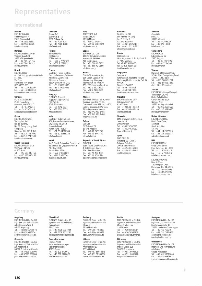
130
04/1
6
Representatives
Germany
International
AugsburgEUCHNER GmbH + Co. KGIngenieur- und VertriebsbüroJulius-Spokojny-Weg 886153 AugsburgTel. +49 821 56786540Fax +49 821 [email protected]
ChemnitzEUCHNER GmbH + Co. KGIngenieur- und VertriebsbüroAm Vogelherd 209627 Bobritzsch-HilbersdorfTel. +49 37325 906000Fax +49 37325 [email protected]
AustriaEUCHNER GmbHSüddruckgasse 42512 TribuswinkelTel. +43 2252 42191Fax +43 2252 [email protected]
BeneluxEUCHNER (BENELUX) BVVisschersbuurt 233356 AE PapendrechtTel. +31 78 615-4766Fax +31 78 [email protected]
BrazilEUCHNER LtdaAv. Prof. Luiz Ignácio Anhaia Mello, no. 4387Vila EmaSão Paulo - SP - BrasilCEP 03295-000Tel. +55 11 29182200Fax +55 11 [email protected]
CanadaIAC & Associates Inc.2105 Fasan DriveOldcastle, ON N0R 1L0Tel. +1 519 737-0311Fax +1 519 [email protected]
ChinaEUCHNER (Shanghai) Trading Co., Ltd.No. 15 building, No. 68 Zhongchuang Road,SongjiangShanghai, 201613, P.R.CTel. +86 21 5774-7090Fax +86 21 [email protected]
Czech RepublicEUCHNER electric s.r.o.Vídenská 134/10261900 BrnoTel. +420 533 443-150Fax +420 533 [email protected]
DüsseldorfEUCHNER GmbH + Co. KGIngenieur- und VertriebsbüroTippgarten 359427 UnnaTel. +49 2308 9337284Fax +49 2308 [email protected]
Essen/DortmundThomas Kreißlfördern - steuern - regelnHackenberghang 8a45133 Essen Tel. +49 201 84266-0Fax +49 201 [email protected]
FreiburgEUCHNER GmbH + Co. KGIngenieur- und VertriebsbüroSteige 579206 BreisachTel. +49 7664 403833Fax +49 7664 [email protected]
LübeckEUCHNER GmbH + Co. KGIngenieur- und VertriebsbüroAm Stadtrand 1323556 LübeckTel. +49 451 88048371Fax +49 451 [email protected]
BerlinEUCHNER GmbH + Co. KGIngenieur- und VertriebsbüroUlmenstraße 115a12621 BerlinTel. +49 30 50508214Fax +49 30 [email protected]
NürnbergEUCHNER GmbH + Co. KGIngenieur- und VertriebsbüroSteiner Straße 22a90522 OberasbachTel. +49 911 6693829Fax +49 911 [email protected]
StuttgartEUCHNER GmbH + Co. KGIngenieur- und VertriebsbüroKohlhammerstraße 1670771 Leinfelden-EchterdingenTel. +49 711 7597-0Fax +49 711 [email protected]@euchner.de
WiesbadenEUCHNER GmbH + Co. KGIngenieur- und VertriebsbüroAdolfsallee 368185 WiesbadenTel. +49 611 98817644Fax +49 611 [email protected]
DenmarkDuelco A/SSystemvej 8 - 109200 Aalborg SVTel. +45 7010 1007Fax +45 7010 [email protected]
FinlandSähkölehto OyHolkkitie 1400880 HelsinkiTel. +358 9 7746420Fax +358 9 [email protected]
FranceEUCHNER France S.A.R.L.Parc d‘Affaires des BellevuesAllée Rosa LuxembourgBâtiment le Colorado95610 ERAGNY sur OISETel. +33 1 3909-9090Fax +33 1 [email protected]
HungaryEUCHNER Ges.mbHMagyarországi FióktelepFSD Park 2.2045 TörökbálintTel. +36 2342 8374Fax +36 2342 [email protected]
IndiaEUCHNER (India) Pvt. Ltd.401, Bremen Business Center,City Survey No. 2562, University RoadAundh, Pune - 411007Tel. +91 20 64016384Fax +91 20 [email protected]
IsraelIlan & Gavish Automation Service Ltd.26 Shenkar St. Qiryat Arie 49513P.O. Box 10118Petach Tikva 49001Tel. +972 3 9221824Fax +972 3 [email protected]
ItalyTRITECNICA SpAViale Lazio 2620135 MilanoTel. +39 02 541941Fax +39 02 [email protected]
JapanEUCHNER Co., Ltd.1662-3 KomakiharashindenKomaki-shi, Aichi-ken485-0012, JapanTel. +81 568 42 0157Fax +81 568 42 [email protected]
KoreaEUCHNER Korea Co., Ltd.115 Gasan Digital 2 - Ro(Gasan-dong, DaeryungTechnotown 3rd Rm 810)153 - 803 Kumchon-Gu, SeoulTel. +82 2 2107-3500Fax +82 2 [email protected]
MexicoEUCHNER México S de RL de CVConjunto Industrial PK Co.Carretera Estatal 431 km. 1+300Ejido El Colorado, El Marqués76246 Querétaro, MéxicoTel. +52 442 402 1485Fax +52 442 402 [email protected]
PolandELTRONPl. Wolnosci 7B50-071 WrocławTel. +48 71 3439755Fax +48 71 [email protected]
Republic of South AfricaRUBICON ELECTRICAL DISTRIBUTORS4 Reith Street, Sidwell6061 Port ElizabethTel. +27 41 451-4359Fax +27 41 [email protected]
RomaniaFirst Electric SRLStr. Ritmului Nr. 1 Bis Ap. 2, Sector 2021675 BucurestiTel. +40 21 2526218Fax +40 21 [email protected]
RussiaVALEX electroUliza Karjer dom 2, Str. 9, Etash 2117449 MoskwaTel. +7 495 41196-35Fax +7 495 [email protected]
SingaporeSentronics Automation & Marketing Pte Ltd.Blk 3, Ang Mo Kio Industrial Park 2A#05-06Singapore 568050Tel. +65 6744 8018Fax +65 6744 [email protected]
SlovakiaEUCHNER electric s.r.o.Vídenská 134/10261900 BrnoTel. +420 533 443-150Fax +420 533 [email protected]
SloveniaSMM proizvodni sistemi d.o.o.Jaskova 182000 MariborTel. +386 2 4502326Fax +386 2 [email protected]
SpainEUCHNER, S.L.Gurutzegi 12 - Local 1Polígono Belartza20018 San SebastianTel. +34 943 316-760Fax +34 943 [email protected]
SwedenCensit ABBox 33133123 VärnamoTel. +46 370 691010Fax +46 370 [email protected]
SwitzerlandEUCHNER AGFalknisstrasse 9a7320 SargansTel. +41 81 720-4590Fax +41 81 [email protected]
TaiwanDaybreak Int‘l (Taiwan) Corp.3F, No. 124, Chung-Cheng RoadShihlin 11145, TaipeiTel. +886 2 8866-1234Fax +886 2 [email protected]
TurkeyEUCHNER Endüstriyel Emniyet Teknolojileri Ltd. ti.Hattat Bahattin Sok.Ceylan Apt. No. 13/AGöztepe Mah.34730 Kadıköy / IstanbulTel. +90 216 359-5656Fax +90 216 [email protected]
United KingdomEUCHNER (UK) Ltd.Unit 2 Petre Drive,SheffieldSouth YorkshireS4 7PZTel. +44 114 2560123Fax +44 114 [email protected]
USAEUCHNER USA Inc.6723 Lyons StreetEast Syracuse, NY 13057Tel. +1 315 701-0315Fax +1 315 [email protected]
EUCHNER USA Inc.Detroit Office130 Hampton CircleRochester Hills, MI 48307Tel. +1 248 537-1092Fax +1 248 [email protected]

131
www.euchner.com
Support hotline You have technical questions about our products or how they can be used?For further questions please contact your local sales representative.
Comprehensive download area You are looking for more information about our products?You can simply and quickly download operating instructions, CAD or ePLAN data and accompanying software for our products at www.euchner.com.
Customer-specifi c solutionsYou need a specifi c solution or have a special requirement?Please contact us. We can manufacture your custom product even in small quantities.
EUCHNER near youYou are looking for a contact at your location? Along with the headquarters in Leinfel-den-Echterdingen, the worldwide sales network includes 16 subsidiaries and numerous representatives in Germany and abroad – you will defi nitely also fi nd us near you.
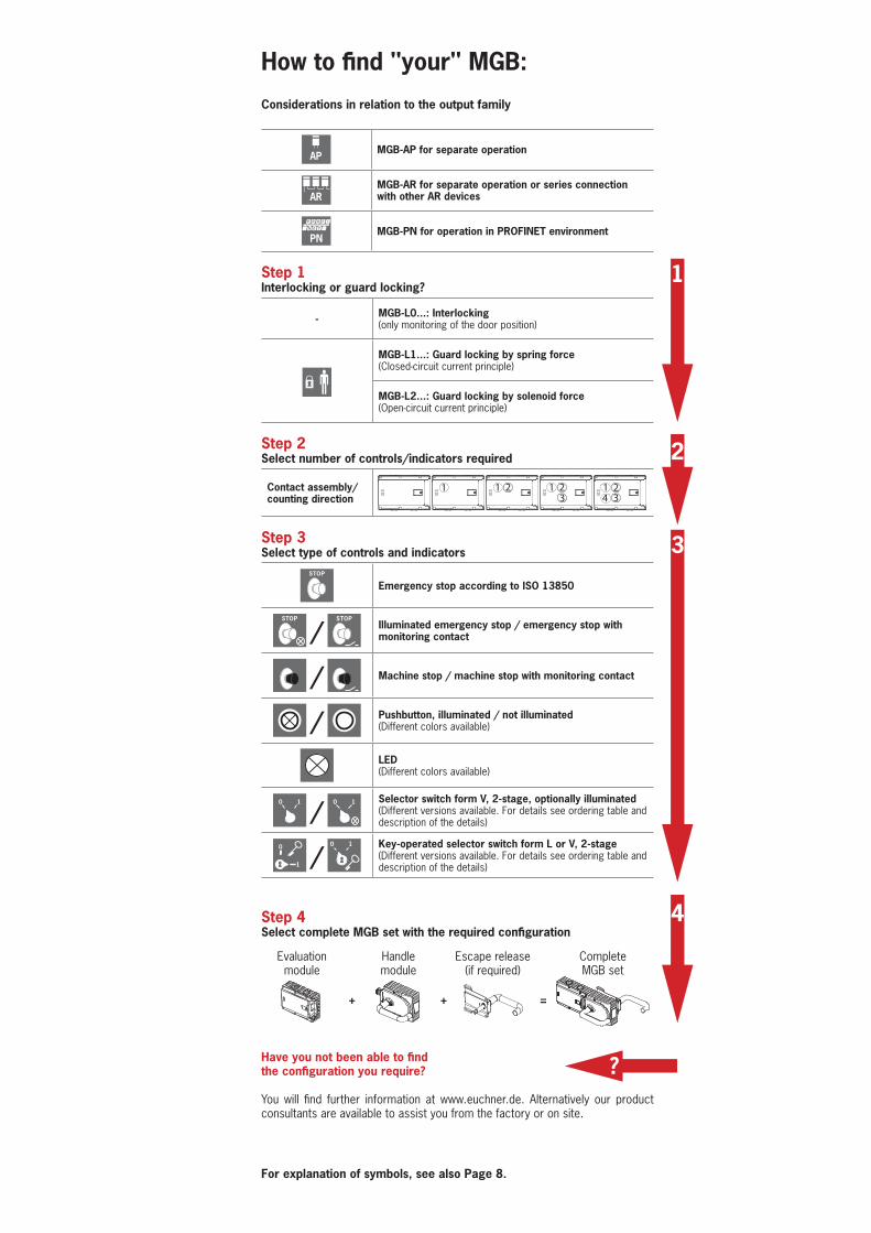
How to find "your" MGB:
Considerations in relation to the output family
AP MGB-AP for separate operation
ARMGB-AR for separate operation or series connection with other AR devices
PNMGB-PN for operation in PROFINET environment
Step 1Interlocking or guard locking?
- MGB-L0...: Interlocking(only monitoring of the door position)
MGB-L1...: Guard locking by spring force (Closed-circuit current principle)
MGB-L2...: Guard locking by solenoid force (Open-circuit current principle)
Step 2 Select number of controls/indicators required
Contact assembly/counting direction
1 1 2 1 23 4 3
21
Step 3 Select type of controls and indicators
STOP
Emergency stop according to ISO 13850
STOP
/ STOP
Illuminated emergency stop / emergency stop with monitoring contact
/ Machine stop / machine stop with monitoring contact
/ Pushbutton, illuminated / not illuminated(Different colors available)
LED(Different colors available)
0 1
/ 0 1 Selector switch form V, 2-stage, optionally illuminated
(Different versions available. For details see ordering table and description of the details)
0
1 / 0 1 Key-operated selector switch form L or V, 2-stage
(Different versions available. For details see ordering table and description of the details)
Step 4 Select complete MGB set with the required configuration
Have you not been able to find the configuration you require?
You will find further information at www.euchner.de. Alternatively our product consultants are available to assist you from the factory or on site.
For explanation of symbols, see also Page 8.
1
2
3
?
4
+ + =
Evaluation module
Handle module
Escape release (if required)
Complete MGB set
How to find „your“
MGB
EUCHNER GmbH + Co. KGKohlhammerstraße 1670771 Leinfelden-EchterdingenGermanyTel. +49 711 7597-0Fax +49 711 [email protected]
EN
106
109-
09-0
3/16
Sub
ject
to te
chni
cal m
odifi
catio
ns w
ithou
t not
ice,
no
liabi
lity
will
be a
ssum
ed fo
r any
det
ail.
© E
UCH
NER
Gm
bH +
Co.
KG
· TA
Related Documents