C53000-L1840-A009-04 SIPROTEC Multifunction Generator, Motor and Transformer Protection Relay 7UM62 Communication module DNP 3.0 Bus mapping / Point lists Preface Table of Contents Notes to SIPROTEC objects 1 DNP V3.0 Device Profile 2 Point lists 3 Glossary Index

Welcome message from author
This document is posted to help you gain knowledge. Please leave a comment to let me know what you think about it! Share it to your friends and learn new things together.
Transcript
C53000-L1840-A009-04
SIPROTEC
Multifunction Generator, Motor and Transformer Protection Relay7UM62
Communication module
DNP 3.0
Bus mapping / Point lists
Preface
Table of Contents
Notes to SIPROTEC objects 1 DNP V3.0 Device Profile 2Point lists 3Glossary
Index

7UM62, DNP 3.0 Bus mapping / Point listsC53000-L1840-A009-04, Release May 2013
Copyright Copyright © SIEMENS AG 2013. All rights reserved. Copying of this document and giving it to others and the use or communication of the contents thereof, are forbidden without ex-press authority. Offenders are liable to the payment of damages. All rights are reserved, especially in the event or grant of a patent or registration of a utility model or design.
Registered trademarks SIPROTEC, SINAUT, SICAM, and DIGSI are registered trade-marks of SIEMENS AG. Other names and terms can be trade-marks the use of which may violate the rights of thirds.
Liability statement We have checked the contents of this manual against the described hardware and software. Nevertheless, deviations may occur so that we cannot guarantee the entire harmony with the product. The contents of this manual will be checked in periodical in-tervals, corrections will be made in the following editions. We look forward to your suggestions for improvement. We reserve the right to make technical improvements with-out notice. Document version: 1.01.00

Preface
Aim of This Manual The manual is devided into the following topics:
• Notes to SIPROTEC objects
• DNP V3.0 Device Profile
• Point lists
General information about design, configuration, and operation of SIPROTEC devices are laid down in the SIPROTEC 4 system manual, order no. E50417-H1176-C151.
Target Audience Protection engineers, commissioning engineers, persons who are involved in setting, testing and service of protection, automation, and control devices, as well as operation personnel in electrical plants and power stations.
Additional literature
This manual describes the DNP 3.0 Device Profile of the SIPROTEC devices.
The following additional manuals inform you about the DNP point lists and the func-tion, operation, assembly and commissioning of the SIPROTEC devices:
Manual Contents Order number
Multifunction Generator, Motor and Transformer Protection RelaySIPROTEC 7UM62
Function, operation, assembly and commissioning of the SIPROTEC device 7UM62
C53000-G1176-C149
DNP 3.0 Communication Database
DNP communication database of the SIPROTEC devices
C53000-L1840-A00
i7UM62, DNP 3.0 Bus mapping / Point listsC53000-L1840-A009-04, Release May 2013
Preface
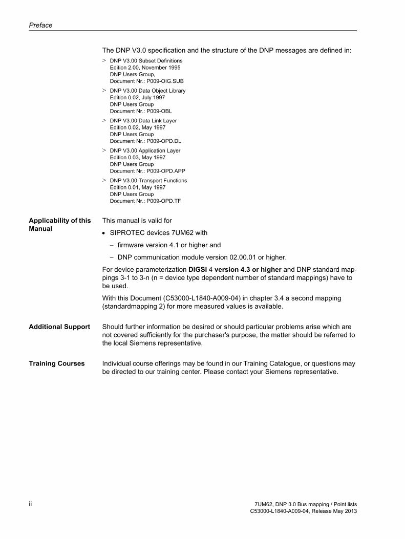
The DNP V3.0 specification and the structure of the DNP messages are defined in:> DNP V3.00 Subset Definitions
Edition 2.00, November 1995DNP Users Group, Document Nr.: P009-OIG.SUB
> DNP V3.00 Data Object LibraryEdition 0.02, July 1997DNP Users GroupDocument Nr.: P009-OBL
> DNP V3.00 Data Link LayerEdition 0.02, May 1997DNP Users GroupDocument Nr.: P009-OPD.DL
> DNP V3.00 Application LayerEdition 0.03, May 1997DNP Users GroupDocument Nr.: P009-OPD.APP
> DNP V3.00 Transport FunctionsEdition 0.01, May 1997DNP Users GroupDocument Nr.: P009-OPD.TF
Applicability of this Manual
This manual is valid for
• SIPROTEC devices 7UM62 with
− firmware version 4.1 or higher and
− DNP communication module version 02.00.01 or higher.
For device parameterization DIGSI 4 version 4.3 or higher and DNP standard map-pings 3-1 to 3-n (n = device type dependent number of standard mappings) have to be used.
With this Document (C53000-L1840-A009-04) in chapter 3.4 a second mapping (standardmapping 2) for more measured values is available.
Additional Support Should further information be desired or should particular problems arise which are not covered sufficiently for the purchaser's purpose, the matter should be referred to the local Siemens representative.
Training Courses Individual course offerings may be found in our Training Catalogue, or questions may be directed to our training center. Please contact your Siemens representative.
ii 7UM62, DNP 3.0 Bus mapping / Point listsC53000-L1840-A009-04, Release May 2013

Preface
Instructions and Warnings
The warnings and notes contained in this manual serve for your own safety and for an appropriate lifetime of the device. Please observe them!
The following terms are used:
DANGER indicates that death, severe personal injury or substantial property damage will result if proper precautions are not taken.
Warning indicates that death, severe personal injury or substantial property damage can result if proper precautions are not taken.
Caution indicates that minor personal injury or property damage can result if proper precau-tions are not taken. This particularly applies to damage on or in the device itself and consequential damage thereof.
Note indicates information about the device or respective part of the instruction manual which is essential to highlight.
QUALIFIED PERSONNEL
For the purpose of this instruction manual and product labels, a qualified person is one who is familiar with the installation, construction and operation of the equipment and the hazards involved. In addition, he has the following qualifications:
• Is trained and authorized to energize, de-energize, clear, ground and tag circuits and equipment in accordance with established safety practices.
• Is trained in the proper care and use of protective equipment in accordance with es-tablished safety practices.
• Is trained in rendering first aid.
Warning! Hazardous voltages are present in this electrical equipment during operation. Non–observance of the safety rules can result in severe personal injury or property dam-age.
Only qualified personnel shall work on and around this equipment after becoming thor-oughly familiar with all warnings and safety notices of this manual as well as with the applicable safety regulations.
The successful and safe operation of this device is dependent on proper handling, in-stallation, operation, and maintenance by qualified personnel under observance of all warnings and hints contained in this manual.
In particular the general erection and safety regulations (e.g. IEC, DIN, VDE, EN or other national and international standards) regarding the correct use of hoisting gear must be observed. Non–observance can result in death, personal injury or substantial property damage.
ii7UM62, DNP 3.0 Bus mapping / Point listsC53000-L1840-A009-04, Release May 2013

Preface
Typographic and Symbol Conven-tions
The following text formats are used when literal information from the device or to the device appear in the text flow:
Parameter names, i.e. designators of configuration or function parameters which may appear word-for-word in the display of the device or on the screen of a personal computer (with operation software DIGSI 4), are marked in bold letters of a mono-space type style.
Parameter options, i.e. possible settings of text parameters, which may appear word-for-word in the display of the device or on the screen of a personal computer (with operation software DIGSI 4), are written in italic style, additionally.
“Annunciations”, i.e. designators for information, which may be output by the relay or required from other devices or from the switch gear, are marked in a monospace type style in quotation marks.
Deviations may be permitted in drawings when the type of designator can be obviously derived from the illustration.
iv 7UM62, DNP 3.0 Bus mapping / Point listsC53000-L1840-A009-04, Release May 2013

Table of Contents
Table of Contents
Preface................................................................................................................................................ 0-i
Table of Contents ............................................................................................................................. 1-1
1 Notes to SIPROTEC objects ............................................................................................................ 1-1
1.1 Binary Inputs / Annunciations.............................................................................................. 1-21.1.1 Error with a summary alarm ................................................................................................ 1-21.1.2 Alarm Summary Event......................................................................................................... 1-2
1.2 Binary Outputs / Commands ............................................................................................... 1-31.2.1 Single Commands ............................................................................................................... 1-31.2.2 Changing the setting group ................................................................................................. 1-3
1.3 Analog Inputs / Measured values ........................................................................................ 1-3
1.4 Metered measurands........................................................................................................... 1-4
2 DNP V3.0 Device Profile ................................................................................................................... 2-1
2.1 Implementation Table .......................................................................................................... 2-2
2.2 Device Profile Document ..................................................................................................... 2-4
Con-17UM62, DNP 3.0 Bus mapping / Point listsC53000-L1840-A009-04, Release May 2013

Table of Contents
3 Point lists........................................................................................................................................... 3-1
3.1 Binary Input Points............................................................................................................... 3-23.1.1 Overcurrent Time Protection I> ........................................................................................... 3-23.1.2 Overcurrent Time Protection I>> ......................................................................................... 3-23.1.3 Inverse Time Overcurrent Protection................................................................................... 3-23.1.4 Thermal Overload Protection............................................................................................... 3-23.1.5 Unbalanced Load Protection ............................................................................................... 3-23.1.6 Sensitive Ground Fault Protection....................................................................................... 3-23.1.7 Stator Ground Fault Protection ............................................................................................ 3-33.1.8 Stator Ground Fault Protection with 3rd harmonic ............................................................... 3-33.1.9 Overvoltage Protection ........................................................................................................ 3-33.1.10 Undervoltage Protection ...................................................................................................... 3-33.1.11 Frequency Protection........................................................................................................... 3-33.1.12 Overexcitation Protection..................................................................................................... 3-33.1.13 Reverse Power Protection................................................................................................... 3-43.1.14 Forward Power Supervision................................................................................................. 3-43.1.15 Fuse Failure Monitor............................................................................................................ 3-43.1.16 Underexcitation Protection................................................................................................... 3-43.1.17 Circuit Breaker Failure Protection........................................................................................ 3-43.1.18 Impedance Protection.......................................................................................................... 3-43.1.19 External Trip Coupling ......................................................................................................... 3-43.1.20 Inadvertent Energisation Protection..................................................................................... 3-53.1.21 Trip Coil Monitor .................................................................................................................. 3-53.1.22 Inverse Undervoltage Protection Up<.................................................................................. 3-53.1.23 Startup Supervision of Motors ............................................................................................. 3-53.1.24 Startup Counter for Motors .................................................................................................. 3-53.1.25 Rotor Ground Fault Protection............................................................................................. 3-53.1.26 DC Voltage/Current Protection ............................................................................................ 3-53.1.27 State of the Out-Of-Step Protection..................................................................................... 3-53.1.28 Differential Protection .......................................................................................................... 3-53.1.29 100% Stator Ground Fault Protection.................................................................................. 3-63.1.30 64R Protection 1- 3 Hz ........................................................................................................ 3-63.1.31 Restricted Ground Fault Protection ..................................................................................... 3-63.1.32 Failure Messages of the Protection Functions..................................................................... 3-63.1.33 Diagnosis ............................................................................................................................. 3-63.1.34 User-defined annunciations................................................................................................. 3-63.1.35 Setting group ....................................................................................................................... 3-73.1.36 User-allocated single-point indications ................................................................................ 3-73.1.37 Double commands - checkback signals and status............................................................. 3-7
3.2 Control Relay Output Blocks/Binary Output Status ...................................................... 3-83.2.1 Internal commands .............................................................................................................. 3-83.2.2 User-allocated single commands......................................................................................... 3-83.2.3 External commands (Double commands)............................................................................ 3-8
Con-2 7UM62, DNP 3.0 Bus mapping / Point listsC53000-L1840-A009-04, Release May 2013
Table of Contents
3.3 Counters............................................................................................................................ 3-10
3.4 Analog Inputs .................................................................................................................... 3-113.4.1 Standardmapping 1 ........................................................................................................... 3-113.4.1.1 Recorded measured values............................................................................................... 3-113.4.1.2 Thermal measured values ................................................................................................. 3-113.4.1.3 Min/Max values.................................................................................................................. 3-113.4.1.4 Statistic values .................................................................................................................. 3-123.4.2 Standardmapping 2 ........................................................................................................... 3-133.4.2.1 Recorded measured values............................................................................................... 3-133.4.2.2 Thermal measured values ................................................................................................. 3-133.4.2.3 Min/Max values.................................................................................................................. 3-133.4.2.4 Statistic values .................................................................................................................. 3-14
Glossary ........................................................................................................................................... G-1
Index .................................................................................................................................................. 1-1
Con-37UM62, DNP 3.0 Bus mapping / Point listsC53000-L1840-A009-04, Release May 2013

Table of Contents
Con-4 7UM62, DNP 3.0 Bus mapping / Point listsC53000-L1840-A009-04, Release May 2013
Notes to SIPROTEC objects 1This chapter contains notes for the use and evaluation of certain SIPROTEC objects which are available via DNP3.0 communication.
1.1 Binary Inputs / Annunciations 1-2
1.2 Binary Outputs / Commands 1-3
1.3 Analog Inputs / Measured values 1-3
1.4 Metered measurands 1-4
1-17UM62, DNP 3.0 Bus mapping / Point listsC53000-L1840-A009-04, Release May 2013

Notes to SIPROTEC objects
1.1 Binary Inputs / Annunciations
1.1.1 Error with a summary alarm
The "Error with a summary alarm" is ON if at least one of the following internal alarms assumes the value ON:
• "Error 5V", "Error neutral CT", "Error 1A/5A wrong", "Error A/D converter".
Reference ref to chap. 3.1.33
1.1.2 Alarm Summary Event
The "Alarm summary event" is indicated, if at least one of the following internal alarms assumes the ON status:
• “Error Board 1“, “Error Board 2“, "Error Board 3“, "Error Board 4“, "Error Board 5“, “Error Board 6“, "Error Board 7“,
• "Alarm NO calibration“, "Failure Battery“, "Alarm Real Time Clock",
• "Failure Phase Sequence", "VT Fuse Failure", "Failure Voltage Balance", "Failure Voltage Summation Phase – Ground", "Failure General Voltage Supervision",
• "Failure Current Balance", "Failure Current Summation", "Failure General Current Supervision".
Reference ret. to chap. 3.1.33
Note
The description of the standard mappings / point lists (ref. to chap. 3) contains the pre-allocation of the mapping files at delivery or first assignment of a mapping in DIGSI 4 to the SIPROTEC device.
Changes of the allocation and the scaling of the measured values are possible in ad-aptation to the concrete installation enviroment (ref. to page i).
Note
Depending on the device composition and the existing protection packages not all of the indicated binary inputs or protection annunciations (and corresponding DNP points) may be available in the SIPROTEC device
1-2 7UM62, DNP 3.0 Bus mapping / Point listsC53000-L1840-A009-04, Release May 2013

Binary Outputs / Commands
1.2 Binary Outputs / Commands
1.2.1 Single Commands
The command output mode (pulse output, continuous output) is changeable for the single commands using parametrization software DIGSI 4.
The switching direction OFF for single commands with pulse output is not permitted and is rejected in the SIPROTEC device.
Reference ref. to chap. 3.2.2
1.2.2 Changing the setting group
Switching on one setting group automatically switches off the current active setting group. Transmission of the value OFF is insignificant for the change of the setting group and is refused by the device.
A change of the setting group is only possible via DNP if the parameter CHANGE TO ANOTHER SETTING GROUP (parameter address = 302) has the value "Protocol".
Reference ref. to chap. 3.2.1
1.3 Analog Inputs / Measured values
Note
The allocation of the output relays to the switching devices and to the output channels is defined during parametrization of the SIPROTEC devices.
Depending on the device composition there may be less than indicated output relays (and corresponding DNP message points) available in the SIPROTEC device.
Note
• Depending on the device composition not all of the indicated analog inputs (and corresponding DNP message points) may be available in the SIPROTEC device.
• The transferred percentage values are with reference to the nominal values of the primary equipment.Changes of the scaling of the measured values are possible in adaptation to the concrete installation enviroment. You find information about this in the manual "SIPROTEC Communication module, DNP 3.0 Communication Database " (ref. to page i).
1-37UM62, DNP 3.0 Bus mapping / Point listsC53000-L1840-A009-04, Release May 2013

Notes to SIPROTEC objects
1.4 Metered measurands
Scaling The scaling of the metered measurands which are derived from measured values refers to:
60000 impulses per hour for S = Snom
Snom = Rated Apparent Power of the Generator (parameter address = 0252)
Example In the parameter set is configured:
Snom = 5.27 MVA
60000 impulses correspond so that:
1 h * 5.27 MVA = 5.27 MVAh
Note
• The type of the update (cyclic, with or without deletion) and the update interval must be programmed for the metered measurands with the parametrization software DIGSI 4.
• The scaling of the metered measurands at binary inputs ("Wp(puls)" and "Wq(puls)") depends on the externally connected pulse generator.
1-4 7UM62, DNP 3.0 Bus mapping / Point listsC53000-L1840-A009-04, Release May 2013
DNP V3.0 Device Profile 2
2.1 Implementation Table 2-2
2.2 Device Profile Document 2-4
2-17UM62, DNP 3.0 Bus mapping / Point listsC53000-L1840-A009-04, Release May 2013

DNP V3.0 Device Profile
2.1 Implementation Table
The following table gives a list of all objects recognized and returned by the SIPROTEC device.
For static objects, requests sent with qualifiers 00, 01, 06, 07 or 08 will be responded with qualifiers 00 or 01.
Requests sent with qualifiers 17 or 28 will be responded with qualifiers 17 or 28.
For change-event objects, qualifiers17 or 28 are always responded.
In the table below text shaded 00, 01 (start stop) indicates Subset Level 3 functionality (beyond Subset Level 2), text shaded as 07, 08 (limited qty) indicates functionality be-yond Subset Level 3.
OBJECTS REQUEST RESPONSE
Object Vari-ation
Description Function Codes(dec)
Qualifier Codes(hex)
Function Codes (dec)
Qualifier Codes(hex)
1 0 Binary Input - Any Variations
1 (read) 00, 01 (start-stop)
06 (no range)
07, 08 (limited qfy)
17, 28 (index)
1 2 Binary Input with Status 1 (read) 00, 01 (start-stop)
06 (no range)
07, 08 (limited qfy)
17, 28 (index)
129 (response) 00, 01 (start-stop)
17, 28 (index)
2 0 Binary Input Change -Any Variations
1 (read) 06 (no range)
07, 08 (limited qfy)
2 2 Binary Input Change with Time 1 (read) 06 (no range)
07, 08 (limited qfy)129 (response)
130 (unsol. resp)17, 28 (index)
10 0 Binary Output - Any Variations
1 (read) 00, 01 (start-stop)
06 (no range)
07, 08 (limited qfy)
17, 28 (index)
10 2 Binary Output with Status 1 (read) 00, 01 (start-stop)
06 (no range)
07, 08 (limited qfy)
17, 28 (index)
129 (response) 00, 01 (start-stop)
17, 28 (index)
12 1 Contol Relay Output Block 3 (select)
4 (operate)
5 (direct op.)
6 (dir. op. noack)
00, 01 (start-stop)
07, 08 (limited qfy)
17, 28 (index)
129 (response) echo of response
20 0 Binary Counter - Any Variations
1 (read) 00, 01 (start-stop)
06 (no range)
07, 08 (limited qfy)
17, 28 (index)
20 1 32-Bit Binary Counter (with Flag)
1 (read) 00, 01 (start-stop)
06 (no range)
07, 08 (limited qfy)
17, 28 (index)
22 0 Counter Change Event -Any Variations
1 (read) 06 (no range)
07, 08 (limited qfy)
22 1 32-Bit Counter Change Event without Time
1 (read) 06 (no range)
07, 08 (limited qfy)
2-2 7UM62, DNP 3.0 Bus mapping / Point listsC53000-L1840-A009-04, Release May 2013

Implementation Table
30 0 16-Bit Analog Input -Any Variations
1 (read) 00, 01 (start-stop)
06 (no range)
07, 08 (limited qfy)
17, 28 (index)
30 1 32-Bit Analog Input with Status 1 (read) 00, 01 (start-stop)
06 (no range)
07, 08 (limited qfy)
17, 28 (index)
129 (response) 00, 01 (start-stop)
17, 28 (index)
30 2 16-Bit Analog Input with Status 1 (read) 00, 01 (start-stop)
06 (no range)
07, 08 (limited qfy)
17, 28 (index)
129 (response) 00, 01 (start-stop)
17, 28 (index)
32 0 Analog Change Event -Any Variations
1 (read) 06 (no range)
07, 08 (limited qfy)
32 1 32-Bit Analog Change Event without Time
1 (read) 06 (no range)
07, 08 (limited qfy)129 (response)
130 (unsol. resp)17, 28 (index)
32 2 16-Bit Analog Change Event without Time
1 (read) 06 (no range)
07, 08 (limited qfy)129 (response)
130 (unsol. resp)17, 28 (index)
50 1 Time and Date 2 (write) 07 (limited qfy = 1)
60 1 Class 0 Data 1 (read) 06 (no range)
60 2 Class 1 Data 1 (read) 06 (no range)
07, 08 (limited qfy)
60 3 Class 2 Data 1 (read) 06 (no range)
07, 08 (limited qfy)
60 4 Class 3 Data 1 (read) 06 (no range)
07, 08 (limited qfy)
80 1 Internal Indications 2 (write) 00 (start-stop)(index must = 7)
OBJECTS REQUEST RESPONSE
Object Vari-ation
Description Function Codes(dec)
Qualifier Codes(hex)
Function Codes (dec)
Qualifier Codes(hex)
2-37UM62, DNP 3.0 Bus mapping / Point listsC53000-L1840-A009-04, Release May 2013

DNP V3.0 Device Profile
2.2 Device Profile Document
DNP V3.0DEVICE PROFILE DOCUMENT
Vendor Name: SIEMENS AG
Device Name: 7UM62Highest DNP Level Supported:
For Requests DNP-L2
For Responses DNP-L2
Device Function:
Master Slave
Notable objects, functions, and/or qualifiers supported in addition to the Highest DNP Levels Supported (the complete list is described in the attached table):
For static (non-change-event) object requests, request qualifier codes 00 and 01 (start-stop), 07 and 08 (lim-ited quantity), and 17 and 28 (index) are supported in addition to request qualifier code 06 (no range). Static object requests sent with qualifiers 00, 01, 06, 07, or 08, will be responded with qualifiers 00 or 01. Static ob-ject requests sent with qualifiers 17 or 28 will be responded with qualifiers 17 or 28. For change-event object requests, qualifiers 17 or 28 are always responded.
16-bit Analog Change Events with Time may be requested.
The write function code for Object 50 (Time and Date), variation 1, is supported.
The features outlined within this Device Profile have successfully passed DNP Conformance Test of Subset Level 2 outlined in DNP3-2000 IED Certification Procedure.
Maximum Data Link Frame Size (octets):
Transmitted____292_____________
Received______292_____________
Maximum Application Fragment Size (octets):
Transmitted _Configurable up to 2048
Received_______2048_______Maximum Data Link Re-tries:
NoneFixed atConfigurable, range _0_to _255_
Maximum Application Layer Re-tries:
NoneConfigurable, range ____ to _______(Fixed is not permitted)
Requires Data Link Layer Confirmation:
NeverAlwaysSometimes If 'Sometimes', when? ______________________________________Configurable If 'Configurable', how? by the protection data processing program DIGSI® 4
2-4 7UM62, DNP 3.0 Bus mapping / Point listsC53000-L1840-A009-04, Release May 2013
Device Profile Document
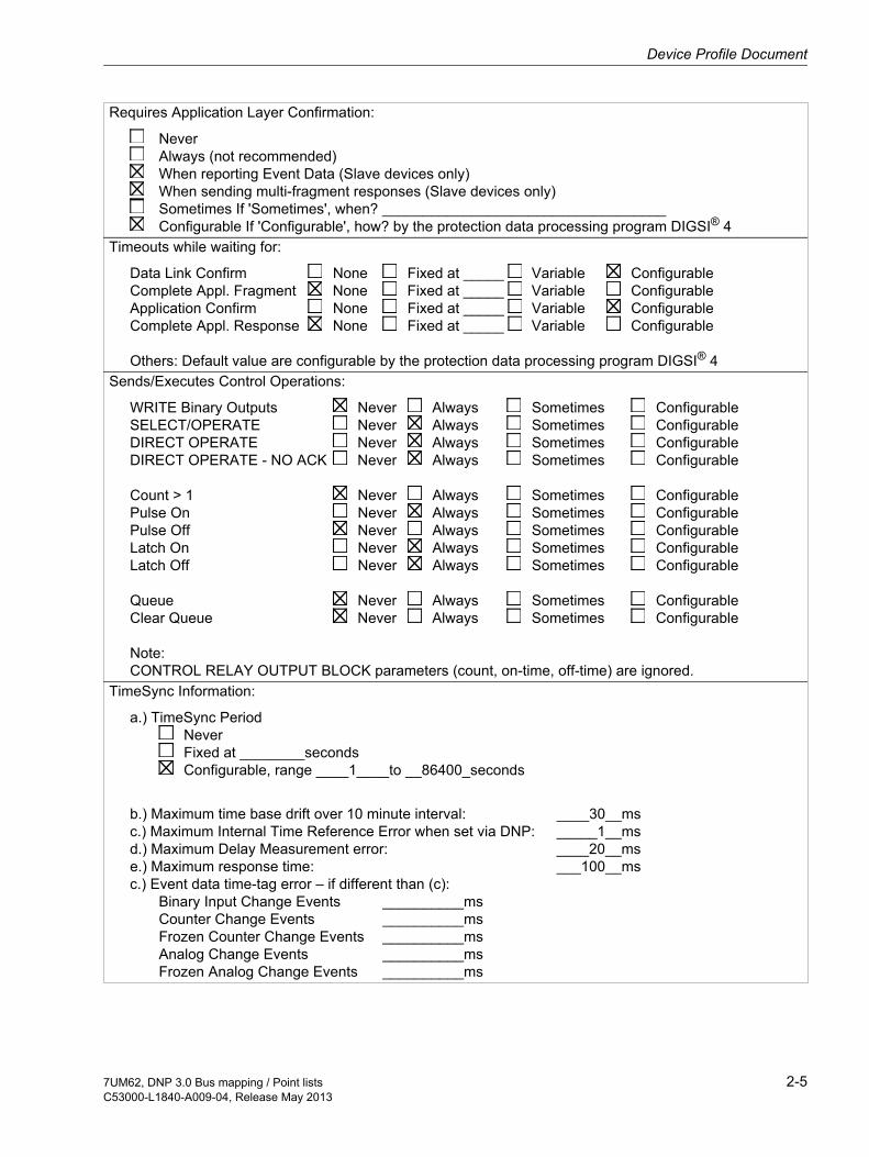
Requires Application Layer Confirmation:
NeverAlways (not recommended)When reporting Event Data (Slave devices only)When sending multi-fragment responses (Slave devices only)Sometimes If 'Sometimes', when? ___________________________________Configurable If 'Configurable', how? by the protection data processing program DIGSI® 4
Timeouts while waiting for:
Data Link Confirm None Fixed at _____ Variable ConfigurableComplete Appl. Fragment None Fixed at _____ Variable ConfigurableApplication Confirm None Fixed at _____ Variable ConfigurableComplete Appl. Response None Fixed at _____ Variable Configurable
Others: Default value are configurable by the protection data processing program DIGSI® 4Sends/Executes Control Operations:
WRITE Binary Outputs Never Always Sometimes ConfigurableSELECT/OPERATE Never Always Sometimes ConfigurableDIRECT OPERATE Never Always Sometimes ConfigurableDIRECT OPERATE - NO ACK Never Always Sometimes Configurable
Count > 1 Never Always Sometimes ConfigurablePulse On Never Always Sometimes ConfigurablePulse Off Never Always Sometimes ConfigurableLatch On Never Always Sometimes ConfigurableLatch Off Never Always Sometimes Configurable
Queue Never Always Sometimes ConfigurableClear Queue Never Always Sometimes Configurable
Note:CONTROL RELAY OUTPUT BLOCK parameters (count, on-time, off-time) are ignored.
TimeSync Information:
a.) TimeSync PeriodNeverFixed at ________secondsConfigurable, range ____1____to __86400_seconds
b.) Maximum time base drift over 10 minute interval: ____30__msc.) Maximum Internal Time Reference Error when set via DNP: _____1__msd.) Maximum Delay Measurement error: ____20__mse.) Maximum response time: ___100__msc.) Event data time-tag error – if different than (c):
Binary Input Change Events __________msCounter Change Events __________msFrozen Counter Change Events __________msAnalog Change Events __________msFrozen Analog Change Events __________ms
2-57UM62, DNP 3.0 Bus mapping / Point listsC53000-L1840-A009-04, Release May 2013

DNP V3.0 Device Profile
Reports Binary Input Change Events when no spe-cific variation requested:
NeverOnly time-tagged Only non-time-tagged Configurable to send both, one or the other (attach explanation)
Reports time-tagged Binary Input Change Events when no specific variation requested:
NeverBinary Input Change With TimeBinary Input Change With Relative TimeConfigurable (attach explanation)
Sends Unsolicited Responses:
Never Configurable (Unsolicited data response mode are switched on/off via the configuration tool )Only certain objects Sometimes (attach explanation)
ENABLE/DISABLE UNSOLICITEDFunction codes supported
Sends Static Data in Unsolicited Responses:
NeverWhen Device RestartsWhen Status Flags Change
No other options are permitted.
Default Counter Object/Variation:
No Counters ReportedConfigurable (attach explanation)Default Object ___20_____Default Variation ___01_____Point-by-point list attached
Sends 32-Bit counters.
Counters Roll Over at:
No Counters ReportedConfigurable (attach explanation)16 Bits32 BitsOther Value _____________Point-by-point list attached
Sends Multi-Fragment Responses: Yes No
2-6 7UM62, DNP 3.0 Bus mapping / Point listsC53000-L1840-A009-04, Release May 2013

Point lists 3
3.1 Binary Input Points 3-2
3.2 Control Relay Output Blocks/Binary Output Status 3-8
3.3 Counters 3-10
3.4 Analog Inputs 3-11
3-17UM62, DNP 3.0 Bus mapping / Point listsC53000-L1840-A009-04, Release May 2013

Point lists
3.1 Binary Input Points
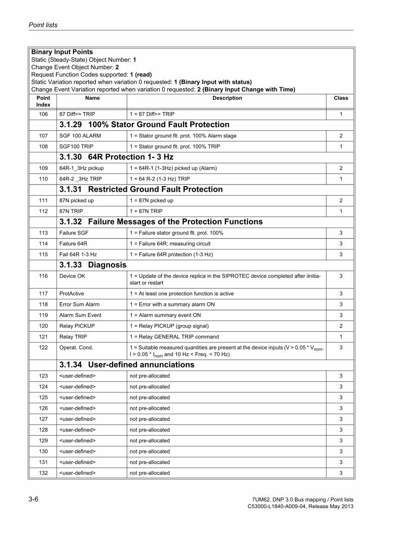
Binary Input PointsStatic (Steady-State) Object Number: 1Change Event Object Number: 2Request Function Codes supported: 1 (read)Static Variation reported when variation 0 requested: 1 (Binary Input with status)Change Event Variation reported when variation 0 requested: 2 (Binary Input Change with Time)
PointIndex
Name Description Class
3.1.1 Overcurrent Time Protection I>0 50/51-1 Ph A PU 1 = 50/51-1 Phase A picked up 2
1 50/51-1 Ph B PU 1 = 50/51-1 Phase B picked up 2
2 50/51-1 Ph C PU 1 = 50/51-1 Phase C picked up 2
3 V< seal in 1 = 50/51-1 undervoltage seal-in 3
4 50/51 TRIP 1 = 50/51 I> TRIP 1
3.1.2 Overcurrent Time Protection I>>5 67 forward 1 = 67 I>> direction forward 3
6 67 backward 1 = 67 I>> direction backward 3
7 50/51-2 Ph A PU 1 = 50/51-2 Phase A picked up 2
8 50/51-2 Ph B PU 1 = 50/51-2 Phase B picked up 2
9 50/51-2 Ph C PU 1 = 50/51-2 Phase C picked up 2
10 51/67 TRIP 1 = 50/51/67 I>> TRIP 1
3.1.3 Inverse Time Overcurrent Protection11 51V Ph A PU 1 = 51V Phase A picked up 2
12 51V Ph B PU 1 = 51V Phase B picked up 2
13 51V Ph C PU 1 = 51V Phase C picked up 2
14 51V TRIP 1 = 51V TRIP 1
3.1.4 Thermal Overload Protection15 49 O/L I Alarm 1 = 49 Overload Current Alarm (I alarm) 3
16 49 O/L Θ Alarm 1 = 49 Thermal Overload Alarm 3
17 49 Th O/L TRIP 1 = 49 Thermal Overload TRIP 1
3.1.5 Unbalanced Load Protection18 46-1 Warn 1 = 46-1 Current warning stage 3
19 46-1 picked up 1 = 46-1 picked up 2
20 46-2 picked up 1 = 46-2 picked up 2
21 46-2 TRIP 1 = 46-2 TRIP of current stage 1
22 46-Θ TRIP 1 = 46 TRIP of thermal stage 1
3.1.6 Sensitive Ground Fault Protection23 Failure 64R 1 = Failure 64R: measuring circuit 3
24 50Ns-1 Pickup 1 = 50Ns-1 Pickup 2
25 50Ns-1 TRIP 1= 50Ns-1 TRIP 1
3-2 7UM62, DNP 3.0 Bus mapping / Point listsC53000-L1840-A009-04, Release May 2013

Binary Input Points
26 50Ns-2 Pickup 1 = 50Ns-2 Pickup 2
27 50Ns-2 TRIP 1 = 50Ns-2 TRIP 1
3.1.7 Stator Ground Fault Protection28 59/67 V0 PU 1 = 59N/67GN V0 picked up 2
29 59/67 I0 PU 1 = 59N/67GN I0 picked up 2
30 59/67 V0 TRIP 1 = 59N/67GN V0 stage TRIP 1
31 59N/67GN TRIP 1 = 59N/67GN TRIP 1
3.1.8 Stator Ground Fault Protection with 3rd harmonic32 27TN/59TN PU 1 = 27TN/59TN with 3rd harmomic picked up 2
33 27TN/59TN TRP 1 = 27TN/59TN with 3rd harmomic TRIP 1
3.1.9 Overvoltage Protection34 59-1 picked up 1 = 59-1 Overvoltage V> picked up 2
35 59-2 picked up 1 = 59-2 Overvoltage V>> picked up 2
36 59-1 TRIP 1 = 59-1 Overvoltage V> TRIP 1
37 59-2 TRIP 1 = 59-2 Overvoltage V>> TRIP 1
3.1.10 Undervoltage Protection38 27-1 picked up 1 = 27-1 Undervoltage V< picked up 2
39 27-2 picked up 1 = 27-2 Undervoltage V<< picked up 2
40 27-1 TRIP 1 = 27-1 Undervoltage V< TRIP 1
41 27-2 TRIP 1 = 27-2 Undervoltage V<< TRIP 1
3.1.11 Frequency Protection42 81-1 picked up 1 = 81-1 picked up 2
43 81-2 picked up 1 = 81-2 picked up 2
44 81-3 picked up 1 = 81-3 picked up 2
45 81-4 picked up 1 = 81-4 picked up 2
46 81-1 TRIP 1 = 81-1 TRIP 1
47 81-2 TRIP 1 = 81-2 TRIP 1
48 81-3 TRIP 1 = 81-3 TRIP 1
49 81-4 TRIP 1 = 81-4 TRIP 1
3.1.12 Overexcitation Protection50 24 warn 1 = 24 V/f warning stage 3
51 24-1 picked up 1 = 24-1 V/f> picked up 2
52 24-2 picked up 1 = 24-2 V/f>> picked up 2
53 24 th.TRIP 1 = 24 TRIP of thermal stage 1
Binary Input PointsStatic (Steady-State) Object Number: 1Change Event Object Number: 2Request Function Codes supported: 1 (read)Static Variation reported when variation 0 requested: 1 (Binary Input with status)Change Event Variation reported when variation 0 requested: 2 (Binary Input Change with Time)
PointIndex
Name Description Class
3-37UM62, DNP 3.0 Bus mapping / Point listsC53000-L1840-A009-04, Release May 2013

Point lists
54 24-2 TRIP 1 = 24-2 TRIP of V/f>> stage 1
3.1.13 Reverse Power Protection55 32R picked up 1 = 32R picked up 2
56 32R TRIP 1 = 32R TRIP 1
57 32R+SV TRIP 1 = 32R TRIP with stop valve 1
3.1.14 Forward Power Supervision58 32F< picked up 1 = 32F P< stage picked up 2
59 32F> picked up 1 = 32F P> stage picked up 2
60 32F P< TRIP 1 = 32F P< stage TRIP 1
61 32F P> TRIP 1 = 32F P> stage TRIP 1
3.1.15 Fuse Failure Monitor62 VT Fuse Failure 1 = Voltage Transformer Fuse Failure 3
3.1.16 Underexcitation Protection63 40 Vexc failure 1 = 40 Exc. voltage failure recognized 3
64 40 picked up 1 = 40 picked up 2
65 40-1 TRIP 1 = 40 characteristic 1 TRIP 1
66 40-2 TRIP 1 = 40 characteristic 2 TRIP 1
67 40&V<TRIP 1 = 40 characteristic&Vexc< TRIP 1
68 40-3 TRIP 1 = 40 characteristic 3 TRIP 1
3.1.17 Circuit Breaker Failure Protection69 50BF pickup 1 = 50BF picked up 2
70 50BF TRIP 1 = 50BF TRIP 1
3.1.18 Impedance Protection71 21 Fault Ph A 1 = 21 Fault detection , Phase A 2
72 21 Fault Ph B 1 = 21 Fault detection , Phase B 2
73 21 Fault Ph C 1 = 21 Fault detection , Phase C 2
74 21 I> & U< 1 = 21 O/C with undervoltage seal in 3
75 21 Z1< TRIP 1 = 21 Z1< TRIP 1
76 21 Z1B< TRIP 1 = 21 Z1B< TRIP 1
77 21 Z2< TRIP 1 = 21 Z2< TRIP 1
78 21 T3> TRIP 1 = 21 T3> TRIP 1
3.1.19 External Trip Coupling79 Ext 1 Gen.TRP 1 = External trip 1: General TRIP 1
80 Ext 2 Gen.TRP 1 = External trip 2: General TRIP 1
Binary Input PointsStatic (Steady-State) Object Number: 1Change Event Object Number: 2Request Function Codes supported: 1 (read)Static Variation reported when variation 0 requested: 1 (Binary Input with status)Change Event Variation reported when variation 0 requested: 2 (Binary Input Change with Time)
PointIndex
Name Description Class
3-4 7UM62, DNP 3.0 Bus mapping / Point listsC53000-L1840-A009-04, Release May 2013

Binary Input Points
81 Ext 3 Gen.TRP 1 = External trip 3: General TRIP 1
82 Ext 4 Gen.TRP 1 = External trip 4: General TRIP 1
3.1.20 Inadvertent Energisation Protection83 50/27 picked up 1 = 50/27 picked up 2
84 50/27 TRIP 1 = 50/27 TRIP 1
3.1.21 Trip Coil Monitor85 FAIL: Trip cir. 1 = 74TC Failure Trip Circuit 3
3.1.22 Inverse Undervoltage Protection Up<86 Vp< picked up 1 = Inverse Undervoltage Vp< picked up 2
87 Vp< TRIP 1 = Inverse Undervoltage Vp< TRIP 1
3.1.23 Startup Supervision of Motors88 48 Rot. locked 1 = 48 Rotor LOCKED after Lock. Rotor Time 3
89 48 picked up 1 = 48 Starting time supervision picked up 2
90 48 TRIP 1 = 48 Starting time supervision TRIP 1
3.1.24 Startup Counter for Motors91 66 TRIP 1 = 66 Restart inhibit motor TRIP 1
3.1.25 Rotor Ground Fault Protection92 64R-1 picked up 1 = 64R-1 picked up 2
93 64R-2 TRIP 1 = 64R-2 TRIP 1
3.1.26 DC Voltage/Current Protection94 DC Prot.pick.up 1 = DC protection picked up 2
95 DC Prot. TRIP 1 = DC protection TRIP 1
3.1.27 State of the Out-Of-Step Protection96 78 det. char. 1 1 = 78 characteristic 1 picked up 2
97 78 det. char. 2 1 = 78 characteristic 2 picked up 2
98 78 TRIP char. 1 1 = 78 TRIP characteristic 1 1
99 78 TRIP char. 2 1 = 78 TRIP characteristic 2 1
3.1.28 Differential Protection100 87 picked up 1 = 87 Differential protection picked up 2
101 87 TRIP 1 = 87 Differential protection TRIP 1
102 87 TRIP Phase A 1 = 87 Differential protection: TRIP Phase A 1
103 87 TRIP Phase B 1 = 87 Differential protection: TRIP Phase B 1
104 87 TRIP Phase C 1 = 87 Differential protection: TRIP Phase C 1
105 87 Diff> TRIP 1 = 87 Differential prot.: TRIP by IDIFF> 1
Binary Input PointsStatic (Steady-State) Object Number: 1Change Event Object Number: 2Request Function Codes supported: 1 (read)Static Variation reported when variation 0 requested: 1 (Binary Input with status)Change Event Variation reported when variation 0 requested: 2 (Binary Input Change with Time)
PointIndex
Name Description Class
3-57UM62, DNP 3.0 Bus mapping / Point listsC53000-L1840-A009-04, Release May 2013
Point lists
106 87 Diff>> TRIP 1 = 87 Diff>> TRIP 1
3.1.29 100% Stator Ground Fault Protection107 SGF 100 ALARM 1 = Stator ground flt. prot. 100% Alarm stage 2
108 SGF100 TRIP 1 = Stator ground flt. prot. 100% TRIP 1
3.1.30 64R Protection 1- 3 Hz109 64R-1_3Hz pickup 1 = 64R-1 (1-3Hz) picked up (Alarm) 2
110 64R-2 _3Hz TRIP 1 = 64 R-2 (1-3 Hz) TRIP 1
3.1.31 Restricted Ground Fault Protection111 87N picked up 1 = 87N picked up 2
112 87N TRIP 1 = 87N TRIP 1
3.1.32 Failure Messages of the Protection Functions113 Failure SGF 1 = Failure stator ground flt. prot. 100% 3
114 Failure 64R 1 = Failure 64R: measuring circuit 3
115 Fail 64R 1-3 Hz 1 = Failure 64R protection (1-3 Hz) 3
3.1.33 Diagnosis116 Device OK 1 = Update of the device replica in the SIPROTEC device completed after iinitia-
start or restart3
117 ProtActive 1 = At least one protection function is active 3
118 Error Sum Alarm 1 = Error with a summary alarm ON 3
119 Alarm Sum Event 1 = Alarm summary event ON 3
120 Relay PICKUP 1 = Relay PICKUP (group signal) 2
121 Relay TRIP 1 = Relay GENERAL TRIP command 1
122 Operat. Cond. 1 = Suitable measured quantities are present at the device inputs (V > 0.05 * Vnom, I > 0.05 * Inom and 10 Hz < Freq. < 70 Hz)
3
3.1.34 User-defined annunciations123 <user-defined> not pre-allocated 3
124 <user-defined> not pre-allocated 3
125 <user-defined> not pre-allocated 3
126 <user-defined> not pre-allocated 3
127 <user-defined> not pre-allocated 3
128 <user-defined> not pre-allocated 3
129 <user-defined> not pre-allocated 3
130 <user-defined> not pre-allocated 3
131 <user-defined> not pre-allocated 3
132 <user-defined> not pre-allocated 3
Binary Input PointsStatic (Steady-State) Object Number: 1Change Event Object Number: 2Request Function Codes supported: 1 (read)Static Variation reported when variation 0 requested: 1 (Binary Input with status)Change Event Variation reported when variation 0 requested: 2 (Binary Input Change with Time)
PointIndex
Name Description Class
3-6 7UM62, DNP 3.0 Bus mapping / Point listsC53000-L1840-A009-04, Release May 2013

Binary Input Points
133 <user-defined> not pre-allocated 3
134 <user-defined> not pre-allocated 3
3.1.35 Setting group135 Group A Setting Group A; ON=1, OFF=0 1
136 Group B Setting Group B; ON=1, OFF=0 1
137 <unnamed> ON=1, OFF=0 1
138 <unnamed> ON=1, OFF=0 1
3.1.36 User-allocated single-point indications 139 <unnamed>1 User input 1; 0 = open, 1 = close 2
140 <unnamed> User input 2; 0 = open, 1 = close 2
141 <unnamed> User input 2; 0 = open, 1 = close 2
142 <unnamed> User input 2; 0 = open, 1 = close 2
143 <unnamed> User input 2; 0 = open, 1 = close 2
144 <unnamed> User input 2; 0 = open, 1 = close 2
145 <unnamed> User input 2; 0 = open, 1 = close 2
146 <unnamed> User input 2; 0 = open, 1 = close 2
147 <unnamed> User input 2; 0 = open, 1 = close 2
148 <unnamed> User input 2; 0 = open, 1 = close 2
149 <unnamed> User input 2; 0 = open, 1 = close 2
150 <unnamed> User input 2; 0 = open, 1 = close 2
151 <unnamed> User input 2; 0 = open, 1 = close 2
152 <unnamed> User input 2; 0 = open, 1 = close 2
153 <unnamed> User input 2; 0 = open, 1 = close 2
154 <unnamed> User input 2; 0 = open, 1 = close 2
3.1.37 Double commands - checkback signals and status155 Switch 1 Input state of switch 1; 0 = open, 1 = close 1
156 Switch 1 Switch 1 failure status; 0 = switch position is open or close, 1 = switch is in an in-termediate position or position state is incorrect.
1
157 Switch 2 Input state of disconnect switch 2; 0 = open, 1 = close 1
158 Switch 2 Switch 2 failure status; 0 = switch position is open or close, 1 = switch is in an in-termediate position or position state is incorrect.
1
1.The names are defined during indication allocation using parametrization software DIGSI 4
Binary Input PointsStatic (Steady-State) Object Number: 1Change Event Object Number: 2Request Function Codes supported: 1 (read)Static Variation reported when variation 0 requested: 1 (Binary Input with status)Change Event Variation reported when variation 0 requested: 2 (Binary Input Change with Time)
PointIndex
Name Description Class
3-77UM62, DNP 3.0 Bus mapping / Point listsC53000-L1840-A009-04, Release May 2013

Point lists
3.2 Control Relay Output Blocks/Binary Output Status
Binary Output Status Points Object Number: 10 Request Function Codes supported: 1 (Read) Default Variation reported when variation 0 requested: 2 (Binary Output Status)
Control Relay Output Blocks/Binary Output Status Object Number: 12 Request Function Codes supported: 3 (select), 4 (operate), 5 (direct operate),
6 (direct operate, no ack)Point In-
dexName Description Supported Control
Relay Output Block Fields
3.2.1 Internal commands0 Group A Select setting group A and deactivate setting group B,C,D
(ref. to chap.1.2.2)Latch On
1 Group B Select setting group B and deactivate setting group A,C,D Latch On
2 reserved Latch On
3 reserved Latch On
3.2.2 User-allocated single commands
Please ref. to chap.1.2.1 for additional notes.
4 <unnamed>1 User output 1 Latch On, Latch Off
5 <unnamed> User output 2 Latch On, Latch Off
6 <unnamed> User output 3 Latch On, Latch Off
7 <unnamed> User output 4 Latch On, Latch Off
8 <unnamed> User output 5 Latch On, Latch Off
9 <unnamed> User output 6 Latch On, Latch Off
10 <unnamed> User output 7 Latch On, Latch Off
11 <unnamed> User output 8 Latch On, Latch Off
12 <unnamed> User output 9 Latch On, Latch Off
13 <unnamed> User output 10 Latch On, Latch Off
14 <unnamed> User output 11 Latch On, Latch Off
15 <unnamed> User output 12 Latch On, Latch Off
16 <unnamed> User output 13 Latch On, Latch Off
17 <unnamed> User output 14 Latch On, Latch Off
18 <unnamed> User output 15 Latch On, Latch Off
19 <unnamed> User output 16 Latch On, Latch Off
3.2.3 External commands (Double commands)20 Switch 1 Trip Switch 1 Trip, Pulse On
(On-Time Fixed2)
3-8 7UM62, DNP 3.0 Bus mapping / Point listsC53000-L1840-A009-04, Release May 2013

Control Relay Output Blocks/Binary Output Status
21 Switch 1 Close Switch 1 Close, Pulse On(On-Time Fixed)
22 Switch 2 Trip Switch 2 Trip, Pulse On (On-Time Fixed)
23 Switch 2 Close Switch 2 Close, Pulse On (On-Time Fixed)
1.The names are defined during indication allocation using parametrization software DIGSI 42.The On-Time is fixed within the SIPROTEC parameter package for each common object.The Control Relay Output Block information on-time will be ignored.
Binary Output Status Points Object Number: 10 Request Function Codes supported: 1 (Read) Default Variation reported when variation 0 requested: 2 (Binary Output Status)
Control Relay Output Blocks/Binary Output Status Object Number: 12 Request Function Codes supported: 3 (select), 4 (operate), 5 (direct operate),
6 (direct operate, no ack)Point In-
dexName Description Supported Control
Relay Output Block Fields
3-97UM62, DNP 3.0 Bus mapping / Point listsC53000-L1840-A009-04, Release May 2013
Point lists
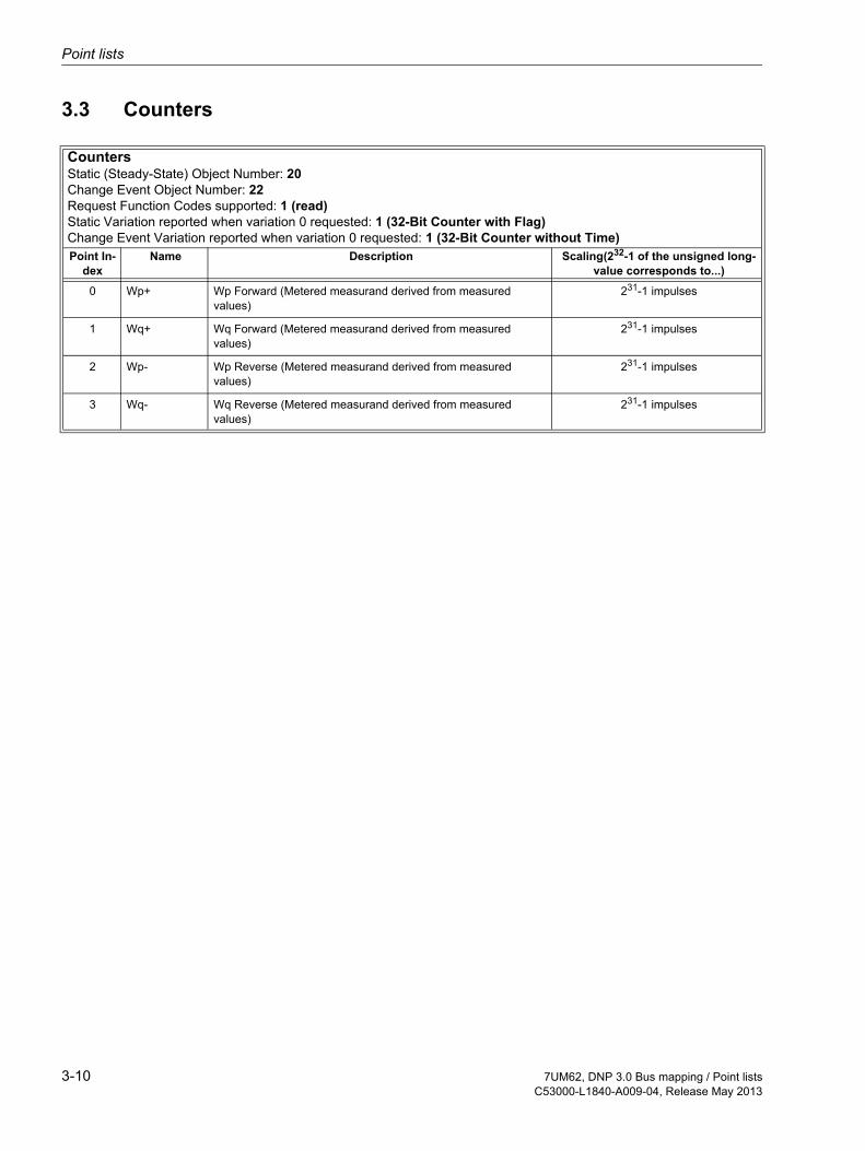
3.3 Counters
Counters Static (Steady-State) Object Number: 20 Change Event Object Number: 22 Request Function Codes supported: 1 (read) Static Variation reported when variation 0 requested: 1 (32-Bit Counter with Flag) Change Event Variation reported when variation 0 requested: 1 (32-Bit Counter without Time) Point In-
dexName Description Scaling(232-1 of the unsigned long-
value corresponds to...)
0 Wp+ Wp Forward (Metered measurand derived from measured values)
231-1 impulses
1 Wq+ Wq Forward (Metered measurand derived from measured values)
231-1 impulses
2 Wp- Wp Reverse (Metered measurand derived from measured values)
231-1 impulses
3 Wq- Wq Reverse (Metered measurand derived from measured values)
231-1 impulses
3-10 7UM62, DNP 3.0 Bus mapping / Point listsC53000-L1840-A009-04, Release May 2013

Analog Inputs
3.4 Analog Inputs
3.4.1 Standardmapping 1
Analog InputsStatic (Steady-State) Object Number: 30Change Event Object Number: 32Request Function Codes supported: 1 (read)Static Variation reported when variation 0 requested: 02 (16-Bit Analog Input)Change Event Variation reported when variation 0 requested:02 (Analog Change Event without Time)Point In-
dexName Description Scaling(32767 corre-
sponds to ...)Default Change Event assigned
Class3.4.1.1 Recorded measured values
0 IA S1= Operat. meas. current A side 1 327.67 % 3
1 IB S1= Operat. meas. current B side 1 327.67 % 3
2 IC S1= Operat. meas. current C side 1 327.67 % 3
3 IA S2= Operat. meas. current A side 2 327.67 % 3
4 IB S2= Operat. meas. current B side 2 327.67 % 3
5 IC S2= Operat. meas. current C side 2 327.67 % 3
6 Va-b= Va-b 327.67 % 3
7 Vb-c= Vb-c 327.67 % 3
8 Vc-a= Vc-a 327.67 % 3
9 P = P (active power) 327.67 % 3
10 Q = Q (reactive power) 327.67 % 3
11 f = Frequency 327.67 Hz 3
12 I2 = I2 (negative sequence) 327.67 % 3
3.4.1.2 Thermal measured values13 Θ / Θ trip = Temperat. rise for warning and trip 327.67 % 3
14 <user-defined>1 not pre-allocated 3
3.4.1.3 Min/Max values15 <user-defined> not pre-allocated 3
16 <user-defined> not pre-allocated 3
17 <user-defined> not pre-allocated 3
18 <user-defined> not pre-allocated 3
19 <user-defined> not pre-allocated 3
20 <user-defined> not pre-allocated 3
21 <user-defined> not pre-allocated 3
22 <user-defined> not pre-allocated 3
23 <user-defined> not pre-allocated 3
24 <user-defined> not pre-allocated 3
25 <user-defined> not pre-allocated 3
3-117UM62, DNP 3.0 Bus mapping / Point listsC53000-L1840-A009-04, Release May 2013

Point lists
26 <user-defined> not pre-allocated 3
If Object 30 Variation 01 (32-Bit Analog Input) requesten, additional:
3.4.1.4 Statistic values27 <user-defined> not pre-allocated 3
28 <user-defined> not pre-allocated 3
29 <user-defined> not pre-allocated 3
30 <user-defined> not pre-allocated 3
31 <user-defined> not pre-allocated 3
32 <user-defined> not pre-allocated 3
33 <user-defined> not pre-allocated 3
34 <user-defined> not pre-allocated 3
35 <user-defined> not pre-allocated 3
36 <user-defined> not pre-allocated 3
37 <user-defined> not pre-allocated 3
38 <user-defined> not pre-allocated 3
1.The names are defined during indication allocation using parametrization software DIGSI 4. On this position <user-defined>all available measured values can be routed here.
Analog InputsStatic (Steady-State) Object Number: 30Change Event Object Number: 32Request Function Codes supported: 1 (read)Static Variation reported when variation 0 requested: 02 (16-Bit Analog Input)Change Event Variation reported when variation 0 requested:02 (Analog Change Event without Time)Point In-
dexName Description Scaling(32767 corre-
sponds to ...)Default Change Event assigned
Class
3-12 7UM62, DNP 3.0 Bus mapping / Point listsC53000-L1840-A009-04, Release May 2013

Analog Inputs
3.4.2 Standardmapping 2
Analog InputsStatic (Steady-State) Object Number: 30Change Event Object Number: 32Request Function Codes supported: 1 (read)Static Variation reported when variation 0 requested: 02 (16-Bit Analog Input)Change Event Variation reported when variation 0 requested:02 (Analog Change Event without Time)Point In-
dexName Description Scaling(32767 corre-
sponds to ...)Default Change Event assigned
Class3.4.2.1 Recorded measured values
0 IA S1= Operat. meas. current A side 1 327.67 % 3
1 IB S1= Operat. meas. current B side 1 327.67 % 3
2 IC S1= Operat. meas. current C side 1 327.67 % 3
3 IA S2= Operat. meas. current A side 2 327.67 % 3
4 IB S2= Operat. meas. current B side 2 327.67 % 3
5 IC S2= Operat. meas. current C side 2 327.67 % 3
6 Va-b= Va-b 327.67 % 3
7 Vb-c= Vb-c 327.67 % 3
8 Vc-a= Vc-a 327.67 % 3
9 P = P (active power) 327.67 % 3
10 Q = Q (reactive power) 327.67 % 3
11 f = Frequency 327.67 Hz 3
12 I2 = I2 (negative sequence) 327.67 % 3
3.4.2.2 Thermal measured values13 Θ / Θ trip = Temperat. rise for warning and trip 327.67 % 3
14 <user-defined>1 not pre-allocated 3
15 <user-defined>1 not pre-allocated 3
16 <user-defined>1 not pre-allocated 3
17 <user-defined>1 not pre-allocated 3
18 <user-defined>1 not pre-allocated 3
19 <user-defined>1 not pre-allocated 3
20 <user-defined>1 not pre-allocated 3
21 <user-defined>1 not pre-allocated 3
22 <user-defined>1 not pre-allocated 3
23 <user-defined>1 not pre-allocated 3
24 <user-defined>1 not pre-allocated 3
3.4.2.3 Min/Max values25 <user-defined> not pre-allocated 3
26 <user-defined> not pre-allocated 3
27 <user-defined> not pre-allocated 3
28 <user-defined> not pre-allocated 3
3-137UM62, DNP 3.0 Bus mapping / Point listsC53000-L1840-A009-04, Release May 2013
Point lists
29 <user-defined> not pre-allocated 3
30 <user-defined> not pre-allocated 3
31 <user-defined> not pre-allocated 3
32 <user-defined> not pre-allocated 3
33 <user-defined> not pre-allocated 3
34 <user-defined> not pre-allocated 3
35 <user-defined> not pre-allocated 3
36 <user-defined> not pre-allocated 3
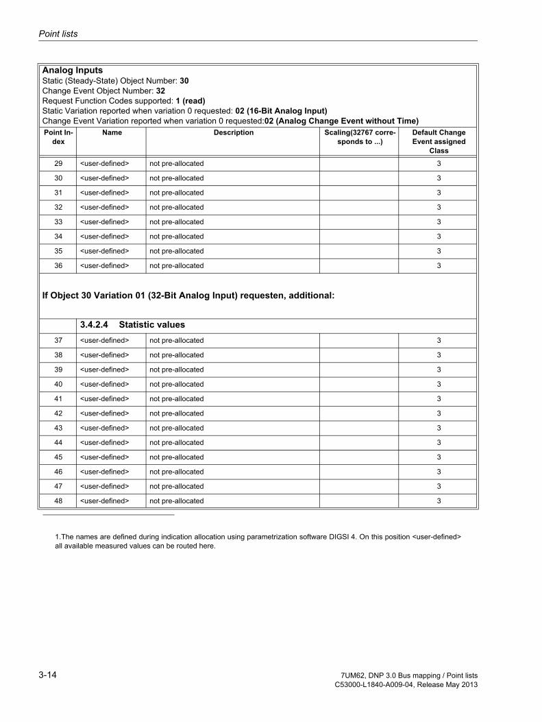
If Object 30 Variation 01 (32-Bit Analog Input) requesten, additional:
3.4.2.4 Statistic values37 <user-defined> not pre-allocated 3
38 <user-defined> not pre-allocated 3
39 <user-defined> not pre-allocated 3
40 <user-defined> not pre-allocated 3
41 <user-defined> not pre-allocated 3
42 <user-defined> not pre-allocated 3
43 <user-defined> not pre-allocated 3
44 <user-defined> not pre-allocated 3
45 <user-defined> not pre-allocated 3
46 <user-defined> not pre-allocated 3
47 <user-defined> not pre-allocated 3
48 <user-defined> not pre-allocated 3
1.The names are defined during indication allocation using parametrization software DIGSI 4. On this position <user-defined>all available measured values can be routed here.
Analog InputsStatic (Steady-State) Object Number: 30Change Event Object Number: 32Request Function Codes supported: 1 (read)Static Variation reported when variation 0 requested: 02 (16-Bit Analog Input)Change Event Variation reported when variation 0 requested:02 (Analog Change Event without Time)Point In-
dexName Description Scaling(32767 corre-
sponds to ...)Default Change Event assigned
Class
3-14 7UM62, DNP 3.0 Bus mapping / Point listsC53000-L1840-A009-04, Release May 2013
Glossary
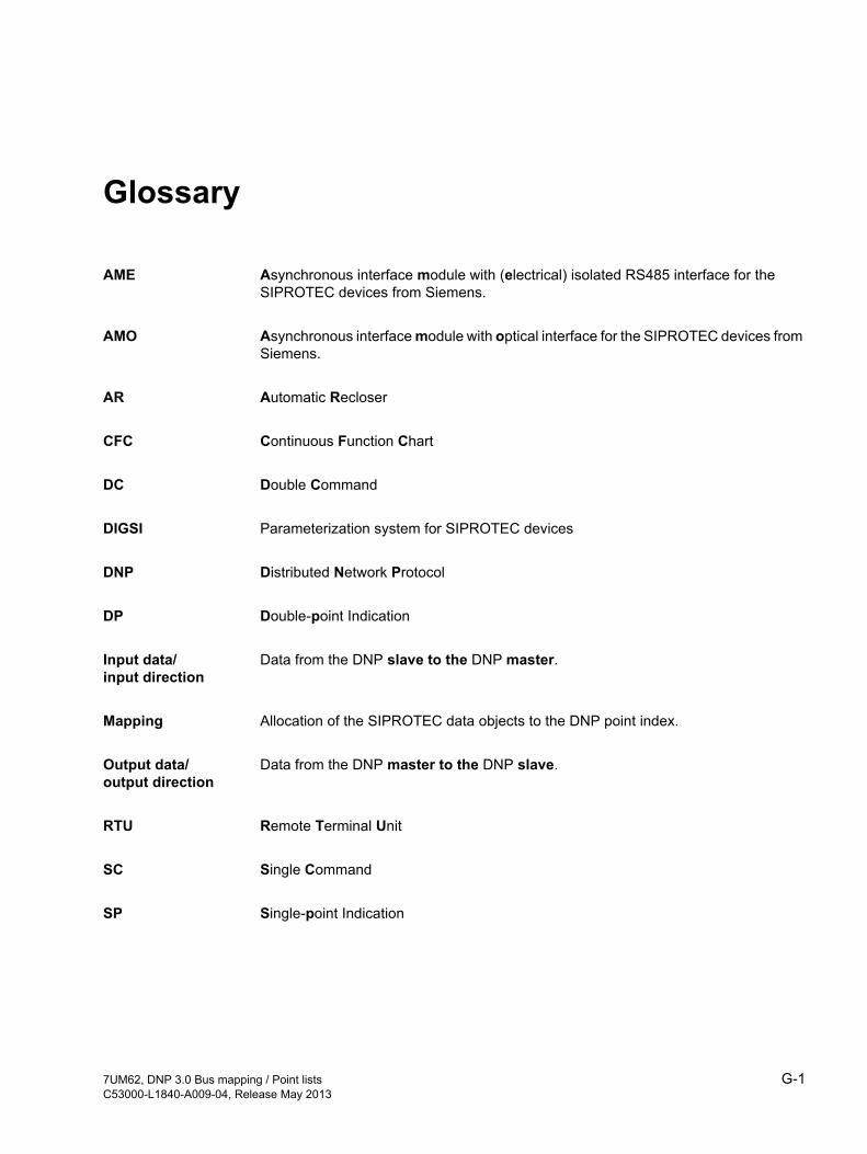
AME Asynchronous interface module with (electrical) isolated RS485 interface for the SIPROTEC devices from Siemens.
AMO Asynchronous interface module with optical interface for the SIPROTEC devices from Siemens.
AR Automatic Recloser
CFC Continuous Function Chart
DC Double Command
DIGSI Parameterization system for SIPROTEC devices
DNP Distributed Network Protocol
DP Double-point Indication
Input data/input direction
Data from the DNP slave to the DNP master.
Mapping Allocation of the SIPROTEC data objects to the DNP point index.
Output data/output direction
Data from the DNP master to the DNP slave.
RTU Remote Terminal Unit
SC Single Command
SP Single-point Indication
G-17UM62, DNP 3.0 Bus mapping / Point listsC53000-L1840-A009-04, Release May 2013

G-2 7UM62, DNP 3.0 Bus mapping / Point listsC53000-L1840-A009-04, Release May 2013

Index
Index
AAdditional support ........................................ 0-iiAlarm summary event .................................. 1-2Analog Inputs ............................1-3, 3-11, 3-13Applicability of manual ................................. 0-ii
BBinary Input Points ................................1-2, 3-2Binary Outputs / Commands .................1-3, 3-8
CCaution (definition) ...................................... 0-iiiCommand output .......................................... 1-3continuous output ......................................... 1-3Copyright ...................................................... 1-iiCounters ..................................................... 3-10
DDanger (definition) ....................................... 0-iiiDevice Profile Document ............................. 2-4DNP messages ............................................ 0-iiDNP V3.0 specification ................................ 0-ii
IImplementation Table .................................. 2-2
MMetered measurands ................................... 1-4
NNote (definition) ...........................................0-iii
PParameter names ........................................ 0-ivParameter options ....................................... 0-ivPulse output ................................................. 1-3pulse output .................................................. 1-3
QQualified personnel (definition) ...................0-iii
SSetting group ................................................ 1-3Subset Level 2 .............................................. 2-2Subset Level 3 .............................................. 2-2Summary alarm ............................................ 1-2Symbol conventions .................................... 0-iv
TTarget audience of manual ........................... 0-iTypographic conventions ............................ 0-iv
VValidity .......................................................... 0-ii
WWarning (definition) .....................................0-iii
I-17UM62, DNP 3.0 Bus mapping / Point listsC53000-L1840-A009-04, Release May 2013

Index
I-2 7UM62, DNP 3.0 Bus mapping / Point listsC53000-L1840-A009-04, Release May 2013
Related Documents