Multidisciplinary Engineering Senior Design Project 06509 RFID Garage Door Entry System Preliminary Design Review 2.24.2006 Team Members: Kenneth Williams, Michael Cummins, Thomas Cervino, Michael Flannery Kate Gleason College of Engineering Rochester Institute of Technology

Multidisciplinary Engineering Senior Design Project 06509 RFID Garage Door Entry System Preliminary Design Review 2.24.2006 Team Members: Kenneth Williams,
Dec 22, 2015
Welcome message from author
This document is posted to help you gain knowledge. Please leave a comment to let me know what you think about it! Share it to your friends and learn new things together.
Transcript
Multidisciplinary Engineering Senior Design
Project 06509 RFID Garage Door Entry SystemPreliminary Design Review2.24.2006
Team Members: Kenneth Williams, Michael Cummins,Thomas Cervino, Michael Flannery
Kate Gleason College of EngineeringRochester Institute of Technology

Design Process
Needs Assessment Concept Development Feasibility Assessment
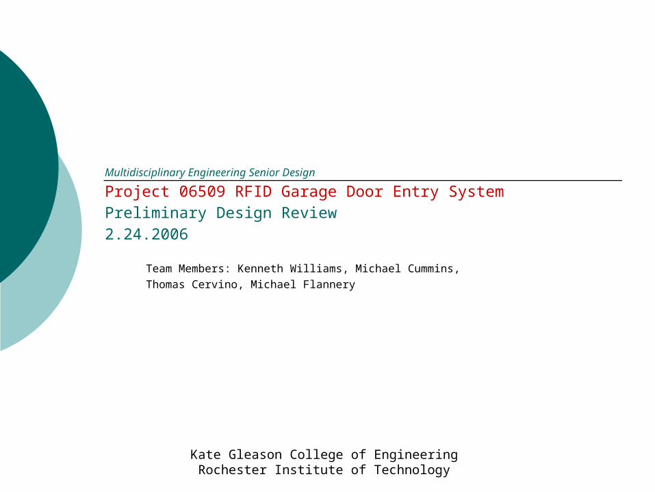
Needs Assessment
RFID Garage Door Opener
Needs to interface with standard garage door
opener (24VDC)
Tag shall have battery life span of at least one year
Range of 30 feetSystem will not interfere
with existing factory setupSurface Mountable
Shall store at least one tag. May store more.
Shall have disabling device on reader. May have one
on tag
Mass Production cost of less than $100
System Shall Use RFIDSystem shall be easy to
installUnit shall interface with all
hardwired controls
Shall have one 120V power connection (hot, neutral,
ground)
Tag shall be battery operated and portable
Deliverables
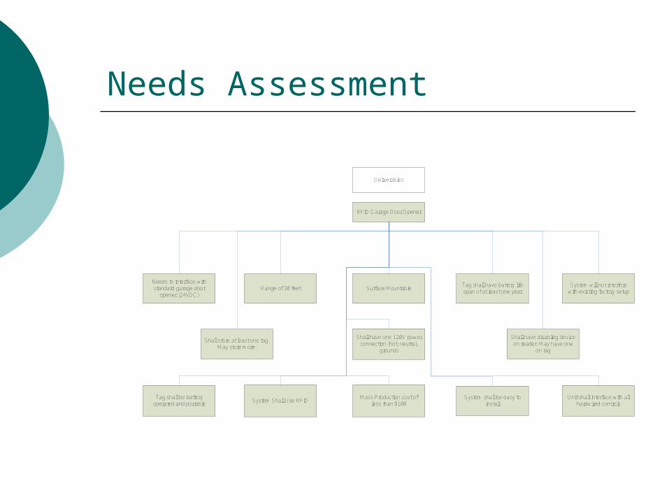
Project Overview
RFID Background What is RFID? Types of RFID tags
Passive Semi-Passive Active
Encoding Options Garage Door Background
Pushbuttons and Safety

Pushbutton Schematic
Garage Door Opener
Garage Door Inputs
Wall Pushbutton
Unmodified Garage Control Setup
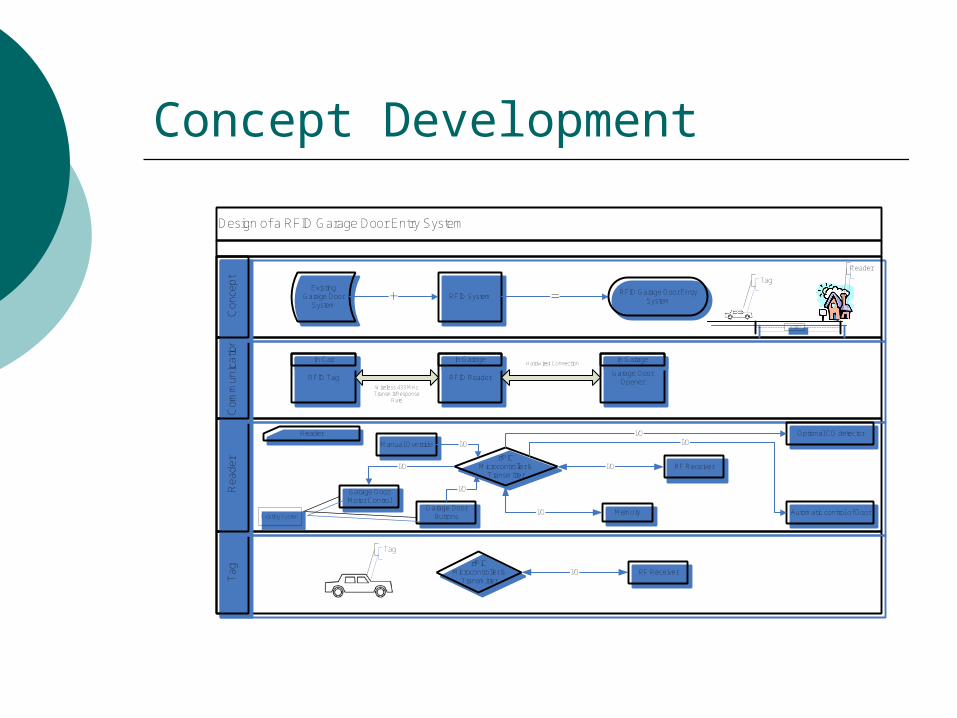
Concept Development
Design of a RFID Garage Door Entry SystemT
ag
Ta
gR
ea
der
Re
ad
er
Co
mm
un
ica
tion
Co
mm
un
ica
tion
Co
nce
pt
Co
nce
pt
Existing Garage Door
SystemRFID System+ =
RFID Tag RFID ReaderGarage Door
Opener
Reader
rfPICMicrocontroller &
Transmitter
Optional CO detector
RF Receiver
Garage Door Motor Control
Garage Door Buttons
Memory
Manual Override
I/O
I/O
I/O
I/O
I/O
I/O
RFID Garage Door Entry System
In Car In Garage In Garage
Reader
>30'
Wireless 433 MHz Transmit/Response
Rate
Hardwired Connection
Existing SystemAutomatic control of Door
I/O
Tag
Tag
rfPICMicrocontroller &
TransmitterI/O RF Receiver

Key Requirements & Critical Parameters (Concept Development)
RFID Reader 433MHz Communication 120VAC 60Hz
RFID Tag 1 Year Battery Life
Communication Protocol Minimal Power Drain ASK
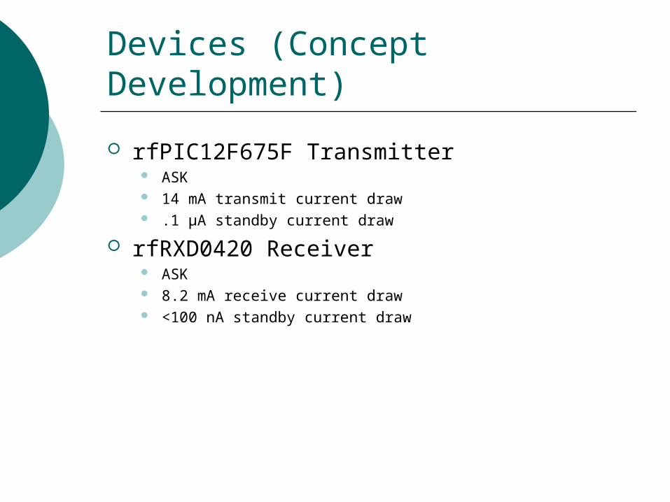
Devices (Concept Development)
rfPIC12F675F Transmitter ASK 14 mA transmit current draw .1 µA standby current draw
rfRXD0420 Receiver ASK 8.2 mA receive current draw <100 nA standby current draw

Detailed Software Design Flow
Software Design
The controller possesses two independent timer modules which will be used in software timing and to generate a standard timed interrupt to detect changes in the
enable switch state.
Initialize:Door is closed.Write variable
Status = ClosedCar is not present.
Start
Call Module
1
Module 1?
Tag in range.Status = Open;Door_Signal();
Tag out of range. Status = Closed;
Timer Done?
5 min wait
1 0
0 1
Call Module
1
Module 1?
Door_Signal();Status = Closed;
Door_Signal();Status = Closed;
Point A
Sleep();
Car is present. Status = Open;
Call Module
1
Module 1?
Wait 60 seconds
Point B
Timer Done?
Status = Closed;Door Signal();
Start();
1 0
1 0
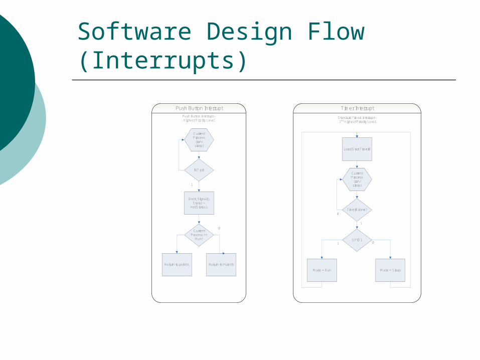
Software Design Flow (Interrupts)
Current Process
(run/sleep)
INT pin
Door_Signal();Status =
not(Status);
Push Button Interrupt-- Highest Priority Level
1
Current Process ==
Run?
Return to point A Return to Point B
0
Push Button Interrupt
Load/Start Timer0
Timer0 done?
GPIO1
Mode = SleepMode = Run
Current Process
(run/sleep)
1 0
0
1
Standard Timed Interrupt-- 2nd Highest Priority Level
Timer Interrupt

Transistor Relay Circuit
Garage Door Opener
Relay
No Connection
Garage Door
Inputs
Rx29.4kΩ
GPIO0 Pin on Microcontroller
VDD (+5VDC)
Relay CoilCoil Voltage: 5VDCCoil Res: 167Ω
RFID Reader
Wall Pushbutton
INT Pin on Microcontroller
Modified Garage Control Setup
VDD (+5VDC)
Garage Door Opener
Garage Door
Inputs
Wall Pushbutton
Unmodified Garage Control Setup
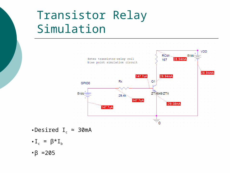
Transistor Relay Simulation
•Desired Ic ≈ 30mA
•Ic = β*Ib
•β =205

Security
Phase 1 (Start signal) Reader -> Transmit Tag -> Receive
Phase 2 (ID) Reader -> Receive Tag -> Transmit
Phase 3 (Security Key) Reader -> Transmit Tag -> Receive
Phase 4 (Password) Reader -> Receive Tag -> Transmit
Security (continued)
Key Features ASK Tag ID Pseudo Random Key Security Function (Password
Generation)

Feasibility Analysis
Power Equation
Battery = 220 Milliamp Hours
365 minutes = 30 seconds transmit/receive x 2 times a day8.2 mA receive draw, 14 mA transmit draw
mAhnAmAhour
mAmAhour
137)1000001(.min60
1min525235)142.8(
min60
1min365
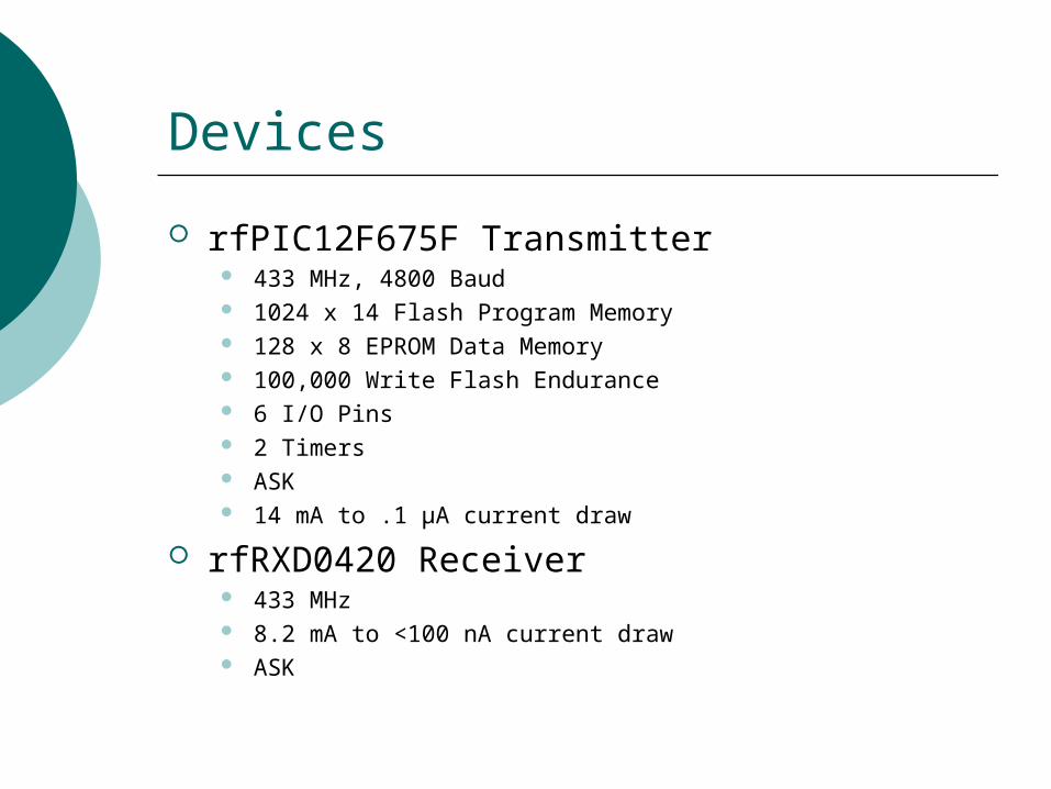
Devices
rfPIC12F675F Transmitter 433 MHz, 4800 Baud 1024 x 14 Flash Program Memory 128 x 8 EPROM Data Memory 100,000 Write Flash Endurance 6 I/O Pins 2 Timers ASK 14 mA to .1 µA current draw
rfRXD0420 Receiver 433 MHz 8.2 mA to <100 nA current draw ASK

BOM & Costs
Total Cost:
$42.74
Digi-Key………………………$21.46
Capacitors
Resistors
Lithium Cell Battery
Coin Cell Battery Holder
Pushbutton Switches
Relay
120V to 5V Transformer
Square Headers and Right Angle Posts
Microchip……………………$5.29
rfRXD0420
rfPIC12F675FMouser…………………………$2.92
DC Power Jack
IRC Resistor
NPN Transistor
RadioShack……………………$9.28
Project Enclosures
Crystek…………………………$2.36
CrystalsmuRata…………………………$0.50
HF Ceramic FilterEPCOS…………………………$0.93
HF SAW Filter

Anticipated Design Challenges
Antenna Design Range Interference
Tag Power Output Power Consumption
Programming Complexity

SD II Project Plan
Build Prototype Test Software Determine Range Test Complete Functionality

Questions

Backup Slides and References
Antenna Length Calculation:
λ=c/f where c is the speed of light and f is the
transmission frequency

Backup Slides and References
R8 is a variable resistance that changes the RF output power
Related Documents