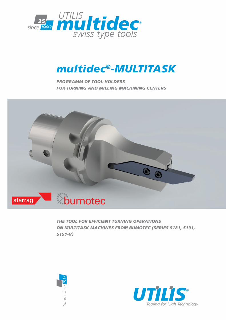
multidec ® -MULTITASK PROGRAMM OF TOOL-HOLDERS FOR TURNING AND MILLING MACHINING CENTERS THE TOOL FOR EFFICIENT TURNING OPERATIONS ON MULTITASK MACHINES FROM BUMOTEC (SERIES S181, S191, S191-V)

Welcome message from author
This document is posted to help you gain knowledge. Please leave a comment to let me know what you think about it! Share it to your friends and learn new things together.
Transcript
multidec®-MULTITASKPROGRAMM OF TOOL-HOLDERS FOR TURNING AND MILLING MACHINING CENTERS
THE TOOL FOR EFFICIENT TURNING OPERATIONS ON MULTITASK MACHINES FROM BUMOTEC (SERIES S181, S191, S191-V)
Utilis AG, Precision ToolsKreuzlingerstrasse 22, CH-8555 Müllheim, Switzerland
[email protected], www.utilis.comPhone 41 52 762 62 62, Fax 41 52 762 62 00+ +
UTI
LIS,
MU
LTID
EC, E
XTR
AC
T BU
MO
TEC
201
8.11
EN
– 4
0083
8
BU
MO
TEC
– 2
01
8 / 1
9 –
EN

Liability/contentsContents of the catalogue is provided with largest care. We can not guarantee for the correctness, completeness and topicality of contents.
Conception/designUtilis AG, Müllheim
Composition/realizationUtilis AG, Müllheim
Photos/3DUtilis AG, Müllheim
CopyrightEach kind of the publication is inadmissible without permission of the Utilis AG.
© Copyright 2018 – UTILIS AG
Imprint
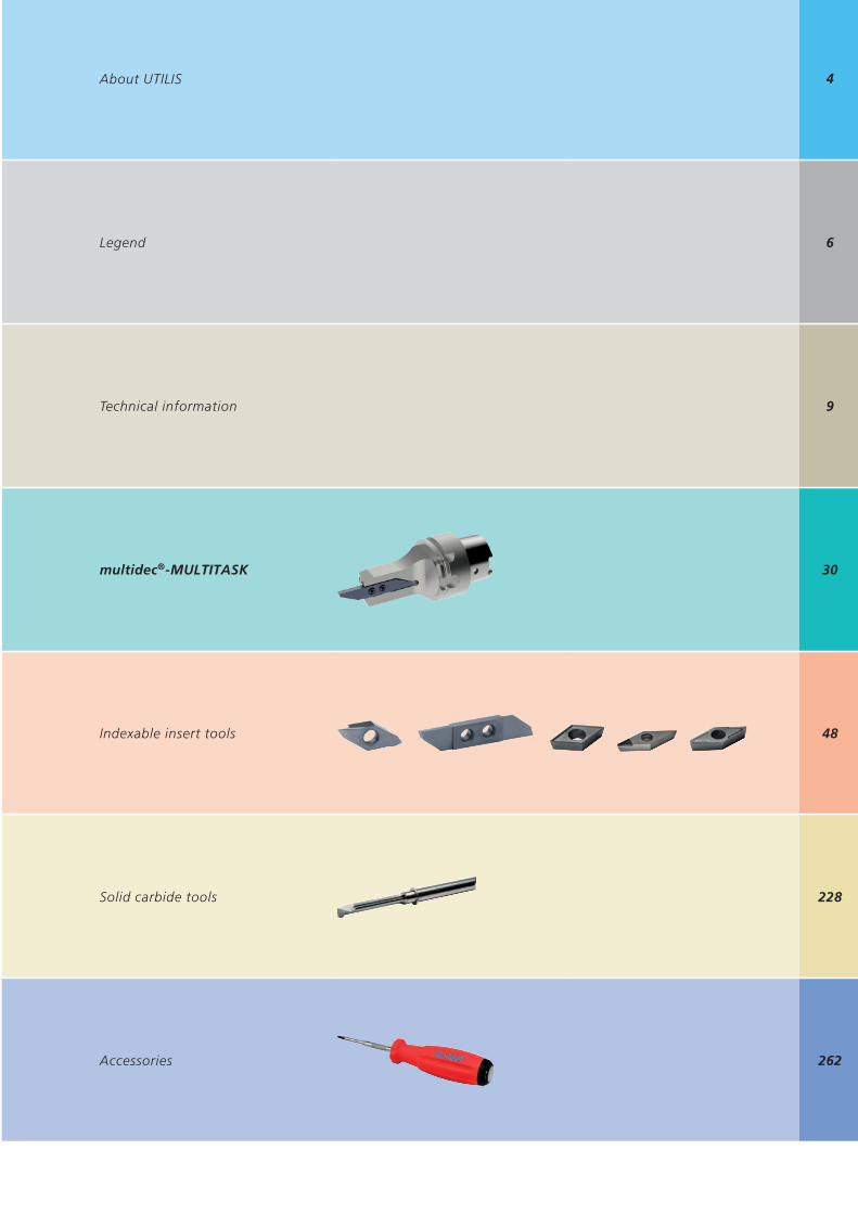
4
6
9
30
48
228
262
About UTILIS
Legend
Technical information
multidec®-MULTITASK
Indexable insert tools
Solid carbide tools
Accessories
4
Michael DrechselPresident of IQNet
Roland GlauserCEO SQS
CERTIFICATEIQNet and SQS
hereby certify that the organisation
has implemented and maintains a
Management Systemwhich fulills the requirements of the following standard(s)
ISO 9001:2008Scope No(s): 18, 29
Issued on: 2015-04-11Validity date: 2018-04-10
Registration Number: CH-11051
IQNet Partners*:AENOR Spain AFNOR Certiication France AIB-Vinçotte International Belgium ANCE-SIGE Mexico APCER Portugal CCC Cyprus
CISQ Italy CQC China CQM China CQS Czech Republic Cro Cert Croatia DQS Holding GmbH Germany FCAV Brazil FONDONORMA Venezuela ICONTEC Colombia IMNC Mexico Inspecta Certiication Finland IRAM Argentina
JQA Japan KFQ Korea MIRTEC Greece MSZT Hungary Nemko AS Norway NSAI Ireland PCBC Poland Quality Austria Austria RR Russia SII Israel SIQ Slovenia SIRIM QAS International Malaysia
SQS Switzerland SRAC Romania TEST St Petersburg Russia TSE Turkey YUQS SerbiaIQNet is represented in the USA by: AFNOR Certiication, CISQ, DQS Holding GmbH and NSAI Inc.
* The list of IQNet partners is valid at the time of issue of this certiicate. Updated information is available under www.iqnet-certiication.com
Utilis AG8555 Müllheim
Switzerland
Certiied area
Whole company
Field of activity
Manufacturing and sale of precision tools
www.utilis.com
Our e-shop offers you a large range of functions and assistance. Take advantage of the product search or the direct service area that we can fulfil your orders, wishes and suggestions quickly.
– Visit our e-shop this very day
– An extensive product portfolio– Multidec® order helper – the guided multidec® product search– UTILIS service area – quick search, contacts and assistance– UTILIS adviser– Tools, information and more
For more than a quarter of a century we have been developing innovative precision tools under our own brand “multidec®”, which is specifically designed to meet the challenges of the watch, medical and dental implant industries. By using state-of-the-art, advanced technology and our extensive know-how in the manufacture of our “multidec® product line”, we are positioning our-selves as a specialist and as one of the leading companies in the market for cutting tools in the metal cutting industry.
UTILIS AG is one of the world’s leading suppliers of precision tools for the metal working industry. Ever since the company was founded in 1915 it has been our declared goal to forge ahead in the production of high quality cutting tools for micromechanics that are valuable and beneficial for our customers. For us, as a traditional, mid-sized, family runed Swiss business, it is only natural that we place the greatest value on precision, service and our customers. We consciously decided to produce our multidec® brand products in Switzerland. It is the only way that we can ensure the established and proven quality of UTILIS brand products that we currently sell in 57 countries around the world. A positive side effect: we ensure, create and maintain employment in Switzerland.
For more than 100 years we have been developing, producing and distributing premium quality cutting tools for micromechanics, watch- and medical tech-nology.
2018 – 25 years of multidec®
24-hour shopping, information and knowledge – and already more than 25,000 products.
At UTILIS, it’s all about cutting. And your success.

5
We have a market-oriented strategy which makes the sustainable benefit of our customers the main focus of our actions. We stand by our claim of being better than the competition.Within the scope of our corporate strategy, both global networking and direct presence play a decisive part on all of the markets that are relevant to us. We are therefore anxious to make our own multidec® brand comprehensive available directly on site via our international representatives.The enclosed general catalogue is excellent for this purpose – as well as personal discussions and our e-shop.
We wish you every success with our multidec® products, and we welcome you to UTILIS
Mario Macario, Managing Director (CEO)
The sustainable profit of your company is at the cutting edge.
6
Article no. 137212 P4563213002 - 1.50 - 8L SC UHM30 HX
Article no. 121114VPGT 1003008 FL TOP UHM30 HX
1602-0.5-2.5 L UHM 30
19
–
L R
UHM
30
UHM
30
SX
UHM
30
HX
1602-0.5-2.5 L … 1602-0.5-2.5 R … ¢ ¢
1602-0.8-5 L … 1602-0.8-5 R … ¢ ¢
1602-1.0-5 L … 1602-1.0-5 R … ¢ ¢
¢ ¢
Different information about multidec® application refer to certain machining methods. In addition, simple symbols inform of the product assortment and where additional products and technical information can be found.
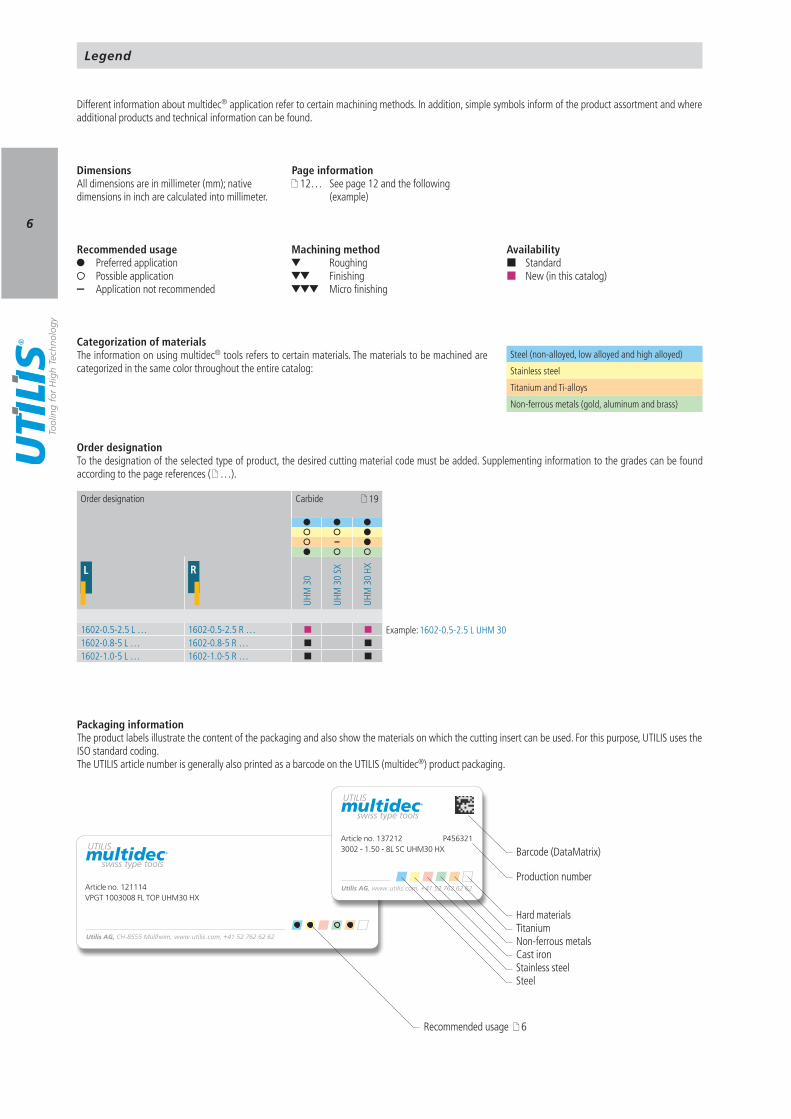
Hard materials Titanium Non-ferrous metals Cast iron Stainless steel Steel
Recommended usage Preferred application Possible application
– Application not recommended
Machining method Roughing
Finishing Micro finishing
Page information 12… See page 12 and the following
(example)
Order designationTo the designation of the selected type of product, the desired cutting material code must be added. Supplementing information to the grades can be found according to the page references ( …).
DimensionsAll dimensions are in millimeter (mm); native dimensions in inch are calculated into millimeter.
Categorization of materialsThe information on using multidec® tools refers to certain materials. The materials to be machined are categorized in the same color throughout the entire catalog:
Steel (non-alloyed, low alloyed and high alloyed)
Stainless steel
Titanium and Ti-alloys
Non-ferrous metals (gold, aluminum and brass)
Recommended usage 6
Packaging informationThe product labels illustrate the content of the packaging and also show the materials on which the cutting insert can be used. For this purpose, UTILIS uses the ISO standard coding.The UTILIS article number is generally also printed as a barcode on the UTILIS (multidec®) product packaging.
Barcode (DataMatrix)
Production number
Availability Standard New (in this catalog)
Legend
Example:
Order designation Carbide
7
R N L
– +
– +
– +
PREMIUM-LINE
VALUE-LINE
STANDARD-LINE
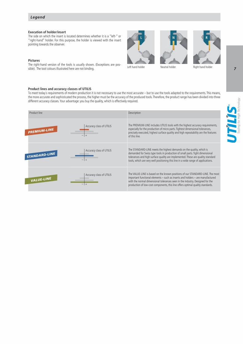
Execution of holder/insertThe side on which the insert is located determines whether it is a “left-” or “right-hand” holder. For this purpose, the holder is viewed with the insert pointing towards the observer.
Left hand holder Neutral holder Right hand holder
PicturesThe right-hand version of the tools is usually shown. (Exceptions are pos-sible). The tool colours illustrated here are not binding.
Legend
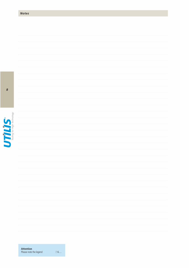
Product lines and accuracy classes of UTILISTo meet today´s requirements of modern production it is not necessary to use the most accurate – but to use the tools adapted to the requirements. This means, the more accurate and sophisticated the process, the higher must be the accuracy of the produced tools. Therefore, the product range has been divided into three different accuracy classes. Your advantage: you buy the quality, which is effectively required.
Product line Description
Accuracy class of UTILIS The PREMIUM-LINE includes UTILIS tools with the highest accuracy requirements, especially for the production of micro parts. Tightest dimensional tolerances, precisely executed, highest surface quality and high repeatability are the features of this line.
Accuracy class of UTILIS The STANDARD-LINE meets the highest demands on the quality, which is demanded for Swiss type tools in production of small parts. Tight dimensional tolerances and high surface quality are implemented. These are quality standard tools, which are very well positioning this line in a wide range of applications.
Accuracy class of UTILIS The VALUE-LINE is based on the known positions of our STANDARD-LINE. The most important functional elements – such as inserts and holders – are manufactured with the normal dimensional tolerances seen in the industry. Designed for the production of low-cost components, this line offers optimal quality standards.
8
AttentionPlease note the legend 6…
Notes

9
10 11 12 19 20 22 24 25 26 27 28
Formulas Comparison of default hardness values Categorization of materials Properties and application range of carbide, cermet and HSS (High Speed Steel) Properties and application range of coatings Properties and application range for diamond Surface quality Improvement of feed rate by drag-cut with TOP System Causes and remedies of wear Problems and their remedies in different cases Working situations
Technical information
10
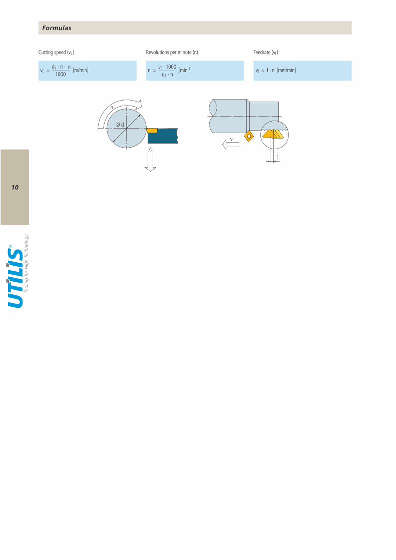
vc = d1 · π · n [m/min]1000
n = vc · 1000 [min-1]d1 · π
vf = f · n [mm/min]
Ø d1
vc
n
vf
f
Formulas
Revolutions per minute (n) Feedrate (vf )Cutting speed (vc )
11
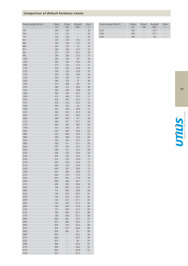
700 200 200 – 28740 210 210 – 29770 220 220 – 30810 230 230 19.2 31840 240 240 21.2 33880 250 250 23 34910 260 260 24.7 35950 270 270 26.1 36980 280 280 27.6 371020 290 290 29 391050 300 300 30.3 401090 310 310 31.5 411120 320 320 32.9 421150 330 330 33.8 431190 340 340 34.9 441230 350 350 36 451260 360 359 37 461300 370 368 38 471330 380 373 38.9 481370 390 385 39.8 491400 400 393 40.7 501440 410 400 41.5 511470 420 407 42.3 521510 430 416 43.2 531540 440 423 44 541580 450 429 44.8 551610 460 435 45.5 561650 470 441 46.3 571680 480 450 47 581720 490 457 47.7 591750 500 465 48.3 601790 510 474 49 611820 520 482 49.6 621860 530 489 50.3 631890 540 496 50.9 641930 550 503 51.5 651960 560 511 52.1 662000 570 520 52.7 672030 580 527 53.3 682070 590 533 53.8 692100 600 533 54.4 702140 610 543 54.9 712170 620 549 55.4 722210 630 555 55.9 732240 640 561 56.4 742280 650 568 56.9 752310 660 574 57.4 752350 670 581 57.9 762380 680 588 58.7 772410 690 595 58.9 782450 700 602 59.3 792480 710 609 59.8 802520 720 616 60.2 812550 730 622 60.7 822590 740 627 61.1 832630 750 633 61.5 832660 760 639 61.9 842700 770 644 62.3 852730 780 650 62.7 862770 790 656 63.1 862800 800 661 63.5 872840 810 666 63.9 872870 820 670 64.3 882910 830 677 64.6 892940 840 682 65 892980 850 – 65.3 903010 860 – 65.7 903050 870 – 66 913080 880 – 66.3 913120 890 – 66.6 923150 900 – 66.9 923190 910 – 67.2 –
3220 920 – 67.5 –3260 930 – 67.7 –3290 940 – 68 –
Tensile strength (N/mm2) Vickers HV
Brinell HB
Rockwell HRC
Shore C
Tensile strength (N/mm2) Vickers HV
Brinell HB
Rockwell HRC
Shore C
Comparison of default hardness values
12
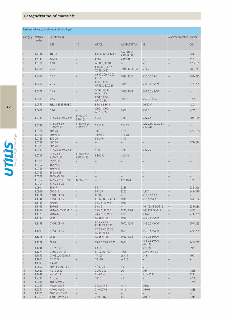
DIN ISO AFNOR AISI/SAE/ASTM JIS (HB)
I 1.0116 St37-3 – E24-U, E24-3, E24-4 A573-81 65, A573 Gr. 58 – – 125
I 1.0144 St44-3 – E28-4 A573-81 – – 125I 1.0301 C 10 – AF 34 C, XC 10 – S 10 C – 125–155
I 1.0401 C 15 – C18, AF3 7 C 12, XC 18, CC12 1015, 1016, 1017 S 15 C – 98–178
I 1.0402 C 22 – AF 42 C 20, 1 C 22, XC 25 1020, 1023 S 20 C, S 33 C – 149–225
I 1.0501 C 35 – C 35, 1 C 35, AF 55 C35, XC 38 1035 S 35 C, S 35 CM – 178–225
I 1.0503 C 45 – C 45, 1 C 45, AF 65 C 45 1045, 1043 S 45 C, S 45 CM – –
I 1.0535 C 55 – C 54, 1 C 55, AF 70 C 55 1055 S 55 C, 1 C 55 – –255
I 1.0570 St52-3, S355 J2G3 C – E 36-3, E 36-4 – SM 50 YA – 180
I 1.0601 C 60 – C 60, 1 C 60, AF 70 C 55 1060 S 58 C – –255
I 1.0715 11 SMn 30, 9 SMn 28 11 SMn 28, 9 SMn 28 S 250 1213 SUM 22 – 107–169
I 1.0718 11 SMnPb 30, 9 SMnPb 28
11 SMnPb 28, 9 SMnPb 28 S 250 Pb 12 L 13 SUM 22 L, SUM 23 L,
SUM 24 L – –
I 1.0721 10 S 20 – 10 F 1 1108 – – 125–155I 1.0722 10 SPb 20 – 10 PbF 2 11 L 08 – – –I 1.0726 35 S 20 – 35 MF 6 1140 – – –I 1.0727 46 S 20 – – – – – 178–214I 1.0728 60 S 20 – – – – – –I 1.0736 11 SMn 37, 9 SMn 36 – S 300 1215 SUM 25 – –
I 1.0737 11 SMnPb 37, 9 SMnPb 36
11 SMnPb 35, 9 SMnPb 36 S 300 Pb 12 L 14 – – –
I 1.0756 35 SPb 20 – – – – – –I 1.0757 46 SPb 20 – – – – – –I 1.0758 60 SPb 20 – – – – – –I 1.0760 38 SMn 28 – – – – – –I 1.0761 38 SMnPb 28 – – – – – –I 1.0762 44 SMn 28, ETG 100 44 SMn 28 – AISI 1144 – – 320I 1.0763 44 SMnPb 28 – – – – – –II 1.0904 55 Si 7 – 55 S 7 9255 – – 235–290II 1.0961 60 SiCr 7 – 60 SC 7 9262 SUP 7 – 245–310I 1.1121 C 10 E, Ck 10 – XC 10 – S 10 C, S 9 CK – –I 1.1141 C 15 E, Ck 15 – XC 12, XC 15, XC 18 1015 S 15, S 15 CK – 149–184I 1.1157 40 Mn 4 – 35 M 5, 40 M 5 1039 – – –I 1.1165 30 Mn 5 – 30 M 5 – SMn 433 H, SCMn 2 – 238–280I 1.1167 36 Mn 5, GS-36 Mn 5 – 35 M 5, 40 M 5 1335, 1541 SMn 438, SCMn 3 – –217I 1.1170 28 Mn 6 – 20 M 5, 28 Mn 6 1330 SCMn 1 – 223–255I 1.1183 Cf 35 – XC 38 H 1 TS 1035 S 35 C, S 35 CM – –
I 1.1191 C 45 E, Ck 45 – C 45, 2 C 45, XC 42 H1, XC 45 1042, 1045 S 45 C, S 45 CM – 207–255
I 1.1203 C 55 E, Ck 55 – 2 C 55, XC 55 H1, XC 54, XC 55 1055 S 55 C, S 55 CM – 229–255
I 1.1213 Cf 53 – XC 48 H 1 TS 1050, 1055 S 50 C, S 50 CM – –
I 1.1221 Ck 60 – C 60, 2 C 60, XC 60 1064 S 58 C, S 60 CM, S 65 CM – 241–255
I 1.1231 C 67 S, Ck 67 – CX 68 – S 70 CM – –92I 1.1274 C 100 S, Ck 101 – C 100, XC 100 1095 SUP 4, SK 4 CSP – –I 1.1545 C 105 U, C 105 W 1 – Y1 105 W 110 SK 3 – 190I 1.1663 C 125 W – Y2 120 W 112 – – –I 1.1730 C 45 W – – – – – –II 1.2067 102 Cr 6, 100 Cr 6 – Y 100 C 6 L 3 SUJ 2 – –III 1.2080 X 210 Cr 12 – Z 200 C 12 D 3 SKD 1 – –225III 1.2083 X 42 Cr 13 – Z 40 C 14 – SUS 420 J 2 – 225III 1.2210 115 CrV 3 – 100 C 3 L 2 – – –250III 1.2311 40 CrMnMo 7 – – – – – –235III 1.2343 X 38 CrMoV 5-1 – Z 38 CDV 5 H 11 SKD 6 – –III 1.2344 X 40 CrMoV 5-1 – Z 40 CDV 5 H 13 SKD 61 – –229III 1.2355 50 CrMoV 13-15 – – – – – –III 1.2363 X 100 CrMoV 5-1 – Z 100 CDV 5 A 2 SKD 12 – –241
Categorization of materials
Steel (non-alloyed, low alloyed and high alloyed)
Category Material number
Specifications Market designation Hardness
13
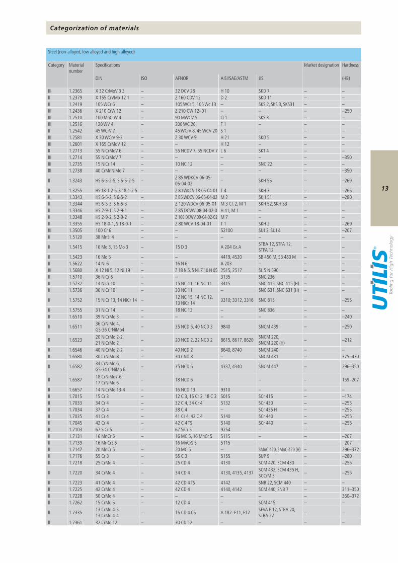
DIN ISO AFNOR AISI/SAE/ASTM JIS (HB)
III 1.2365 X 32 CrMoV 3 3 – 32 DCV 28 H 10 SKD 7 – –II 1.2379 X 155 CrVMo 12 1 – Z 160 CDV 12 D 2 SKD 11 – –II 1.2419 105 WCr 6 – 105 WCr 5, 105 Wc 13 – SKS 2, SKS 3, SKS31 – –III 1.2436 X 210 CrW 12 – Z 210 CW 12–01 – – – –250III 1.2510 100 MnCrW 4 – 90 MWCV 5 O 1 SKS 3 – –III 1.2516 120 WV 4 – 200 WC 20 F 1 – – –II 1.2542 45 WCrV 7 – 45 WCrV 8, 45 WCV 20 S 1 – – –III 1.2581 X 30 WCrV 9-3 – Z 30 WCV 9 H 21 SKD 5 – –III 1.2601 X 165 CrMoV 12 – – H 12 – – –II 1.2713 55 NiCrMoV 6 – 55 NCDV 7, 55 NCDV 7 L 6 SKT 4 – –III 1.2714 55 NiCrMoV 7 – – – – – –350III 1.2735 15 NiCr 14 – 10 NC 12 – SNC 22 – –III 1.2738 40 CrMnNiMo 7 – – – – – –350
II 1.3243 HS 6-5-2-5, S 6-5-2-5 – Z 85 WDKCV 06-05-05-04-02 – SKH 55 – –269
II 1.3255 HS 18-1-2-5, S 18-1-2-5 – Z 80 WKCV 18-05-04-01 T 4 SKH 3 – –265II 1.3343 HS 6-5-2, S 6-5-2 – Z 85 WDCV 06-05-04-02 M 2 SKH 51 – –280II 1.3344 HS 6-5-3, S 6-5-3 – Z 120 WDCV 06-05-01 M 3 Cl. 2, M 1 SKH 52, SKH 53 – –II 1.3346 HS 2-9-1, S 2-9-1 – Z 85 DCWV 08-04-02-0 H 41, M 1 – – –II 1.3348 HS 2-9-2, S 2-9-2 – Z 100 DCWV 09-04-02-02 M 7 – – –II 1.3355 HS 18-0-1, S 18-0-1 – Z 80 WCV 18-04-01 T 1 SKH 2 – –269III 1.3505 100 Cr 6 – – 52100 SUJ 2, SUJ 4 – –207II 1.5120 38 MnSi 4 – – – – – –
II 1.5415 16 Mo 3, 15 Mo 3 – 15 D 3 A 204 Gr. A STBA 12, STFA 12, STPA 12 – –
II 1.5423 16 Mo 5 – – 4419, 4520 SB 450 M, SB 480 M – –II 1.5622 14 Ni 6 – 16 N 6 A 203 – – –III 1.5680 X 12 Ni 5, 12 Ni 19 – Z 18 N 5, 5 Ni, Z 10 N 05 2515, 2517 SL 5 N 590 – –II 1.5710 36 NiCr 6 – – 3135 SNC 236 – –II 1.5732 14 NiCr 10 – 15 NC 11, 16 NC 11 3415 SNC 415, SNC 415 (H) – –II 1.5736 36 NiCr 10 – 30 NC 11 – SNC 631, SNC 631 (H) – –
II 1.5752 15 NiCr 13, 14 NiCr 14 – 12 NC 15, 14 NC 12, 13 NiCr 14 3310; 3312, 3316 SNC 815 – –255
II 1.5755 31 NiCr 14 – 18 NC 13 – SNC 836 – –II 1.6510 39 NiCrMo 3 – – – – – –240
II 1.6511 36 CrNiMo 4, GS-36 CrNiMo4 – 35 NCD 5, 40 NCD 3 9840 SNCM 439 – –250
II 1.6523 20 NiCrMo 2-2, 21 NiCrMo 2 – 20 NCD 2, 22 NCD 2 8615, 8617, 8620 SNCM 220,
SNCM 220 (H) – –212
II 1.6546 40 NiCrMo 2-2 – 40 NCD 2 8640, 8740 SNCM 240 – –II 1.6580 30 CrNiMo 8 – 30 CND 8 – SNCM 431 – 375–430
II 1.6582 34 CrNiMo 6, GS-34 CrNiMo 6 – 35 NCD 6 4337, 4340 SNCM 447 – 296–350
II 1.6587 18 CrNiMo7-6, 17 CrNiMo 6 – 18 NCD 6 – – – 159–207
II 1.6657 14 NiCrMo 13-4 – 16 NCD 13 9310 – – –II 1.7015 15 Cr 3 – 12 C 3, 15 Cr 2, 18 C 3 5015 SCr 415 – –174II 1.7033 34 Cr 4 – 32 C 4, 34 Cr 4 5132 SCr 430 – –255II 1.7034 37 Cr 4 – 38 C 4 – SCr 435 H – –255II 1.7035 41 Cr 4 – 41 Cr 4, 42 C 4 5140 SCr 440 – –255II 1.7045 42 Cr 4 – 42 C 4 TS 5140 SCr 440 – –255II 1.7103 67 SiCr 5 – 67 SiCr 5 9254 – – –II 1.7131 16 MnCr 5 – 16 MC 5, 16 MnCr 5 5115 – – –207II 1.7139 16 MnCrS 5 – 16 MnCrS 5 5115 – – –207II 1.7147 20 MnCr 5 – 20 MC 5 – SMnC 420, SMnC 420 (H) – 296–372II 1.7176 55 Cr 3 – 55 C 3 5155 SUP 9 – –280II 1.7218 25 CrMo 4 – 25 CD 4 4130 SCM 420, SCM 430 – –255
II 1.7220 34 CrMo 4 – 34 CD 4 4130, 4135, 4137 SCM 432, SCM 435 H, SCCrM 3 – –255
II 1.7223 41 CrMo 4 – 42 CD 4 TS 4142 SNB 22, SCM 440 – –II 1.7225 42 CrMo 4 – 42 CD 4 4140, 4142 SCM 440, SNB 7 – 311–350II 1.7228 50 CrMo 4 – – – – – 360–372II 1.7262 15 CrMo 5 – 12 CD 4 – SCM 415 – –
II 1.7335 13 CrMo 4-5, 13 CrMo 4-4 – 15 CD 4.05 A 182–F11, F12 SFVA F 12, STBA 20,
STBA 22 – –
II 1.7361 32 CrMo 12 – 30 CD 12 – – – –
Categorization of materials
Steel (non-alloyed, low alloyed and high alloyed)
Category Material number
Specifications Market designation Hardness
14
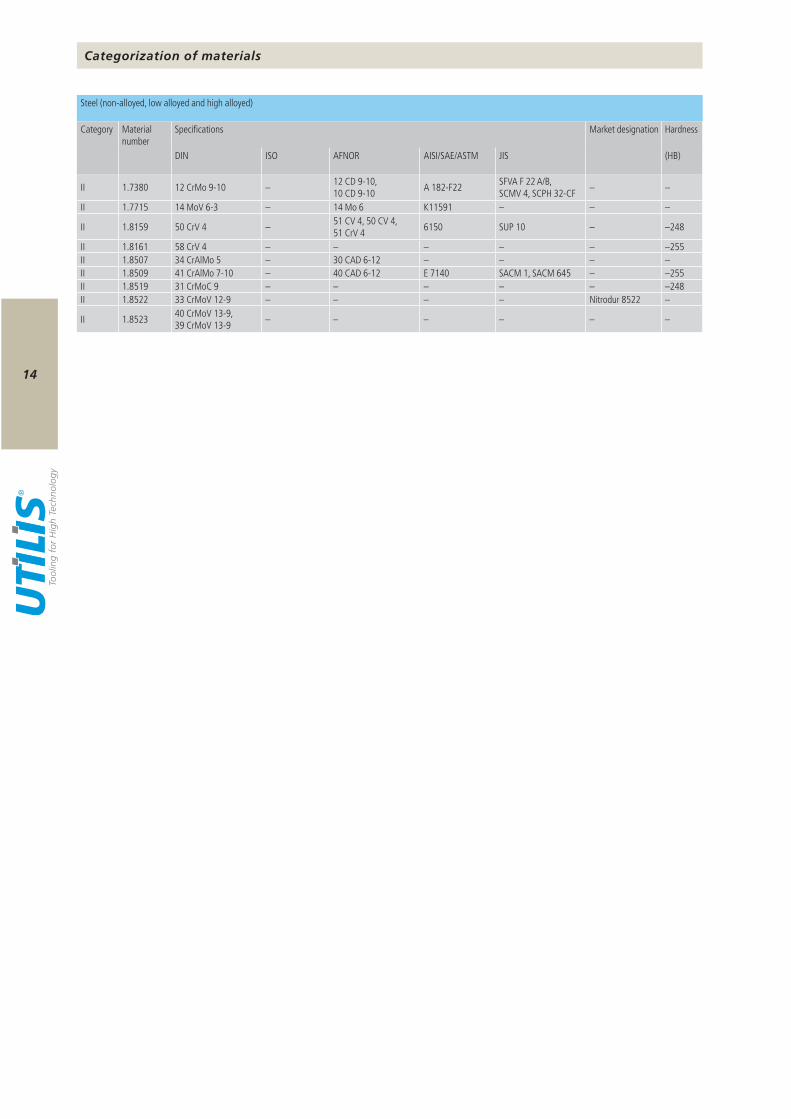
DIN ISO AFNOR AISI/SAE/ASTM JIS (HB)
II 1.7380 12 CrMo 9-10 – 12 CD 9-10, 10 CD 9-10 A 182-F22 SFVA F 22 A/B,
SCMV 4, SCPH 32-CF – –
II 1.7715 14 MoV 6-3 – 14 Mo 6 K11591 – – –
II 1.8159 50 CrV 4 – 51 CV 4, 50 CV 4, 51 CrV 4 6150 SUP 10 – –248
II 1.8161 58 CrV 4 – – – – – –255II 1.8507 34 CrAlMo 5 – 30 CAD 6-12 – – – –II 1.8509 41 CrAlMo 7-10 – 40 CAD 6-12 E 7140 SACM 1, SACM 645 – –255II 1.8519 31 CrMoC 9 – – – – – –248II 1.8522 33 CrMoV 12-9 – – – – Nitrodur 8522 –
II 1.8523 40 CrMoV 13-9, 39 CrMoV 13-9 – – – – – –
Categorization of materials
Steel (non-alloyed, low alloyed and high alloyed)
Category Material number
Specifications Market designation Hardness
15
DIN ISO AFNOR AISI/SAE/ASTM JIS (HB)
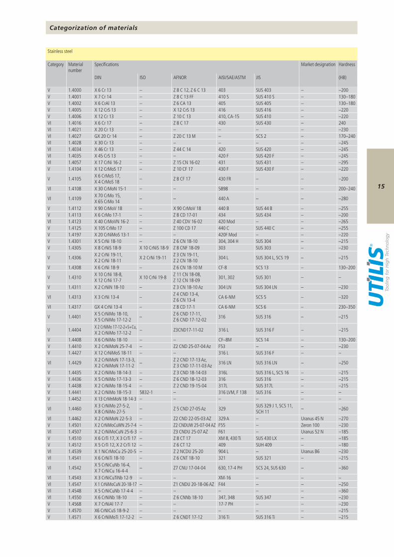
V 1.4000 X 6 Cr 13 – Z 8 C 12, Z 6 C 13 403 SUS 403 – –200V 1.4001 X 7 Cr 14 – Z 8 C 13 FF 410 S SUS 410 S – 130–180V 1.4002 X 6 CrAl 13 – Z 6 CA 13 405 SUS 405 – 130–180V 1.4005 X 12 CrS 13 – X 12 CrS 13 416 SUS 416 – –220V 1.4006 X 12 Cr 13 – Z 10 C 13 410, CA-15 SUS 410 – –220VI 1.4016 X 6 Cr 17 – Z 8 C 17 430 SUS 430 – 240VI 1.4021 X 20 Cr 13 – – – – – –230VI 1.4027 GX 20 Cr 14 – Z 20 C 13 M – SCS 2 – 170–240VI 1.4028 X 30 Cr 13 – – – – – –245VI 1.4034 X 46 Cr 13 – Z 44 C 14 420 SUS 420 – –245VI 1.4035 X 45 CrS 13 – – 420 F SUS 420 F – –245VI 1.4057 X 17 CrNi 16-2 – Z 15 CN 16-02 431 SUS 431 – –295V 1.4104 X 12 CrMoS 17 – Z 10 CF 17 430 F SUS 430 F – –220
V 1.4105 X 6 CrMoS 17, X 4 CrMoS 18 – Z 8 CF 17 430 FR – – –200
VI 1.4108 X 30 CrMoN 15-1 – – 5898 – – 200–240
VI 1.4109 X 70 CrMo 15, X 65 CrMo 14 – – 440 A – – –280
V 1.4112 X 90 CrMoV 18 – X 90 CrMoV 18 440 B SUS 44 B – –255V 1.4113 X 6 CrMo 17-1 – Z 8 CD 17-01 434 SUS 434 – –200VI 1.4123 X 40 CrMoVN 16-2 – Z 40 CDV 16-02 420 Mod – – –265V 1.4125 X 10⁵ CrMo 17 – Z 100 CD 17 440 C SUS 440 C – –255V 1.4197 X 20 CrNiMoS 13-1 – – 420F Mod – – –220V 1.4301 X 5 CrNi 18-10 – Z 6 CN 18-10 304, 304 H SUS 304 – –215V 1.4305 X 8 CrNiS 18-9 X 10 CrNiS 18-9 Z 8 CNF 18-09 303 SUS 303 – –230
V 1.4306 X 2 CrNi 19-11, X 2 CrNi 18-11 X 2 CrNi 19-11 Z 3 CN 19-11,
Z 2 CN 18-10 304 L SUS 304 L, SCS 19 – –215
V 1.4308 X 6 CrNi 18-9 – Z 6 CN 18-10 M CF-8 SCS 13 – 130–200
V 1.4310 X 10 CrNi 18-8, X 12 CrNi 17-7 X 10 CrNi 19-8 Z 11 CN 18-08,
Z 12 CN 18-09 301, 302 SUS 301 – –
V 1.4311 X 2 CrNiN 18-10 – Z 3 CN 18-10 Az 304 LN SUS 304 LN – –230
VI 1.4313 X 3 CrNi 13-4 – Z 4 CND 13-4, Z 6 CN 13-4 CA 6-NM SCS 5 – –320
VI 1.4317 GX 4 CrNi 13-4 – Z 8 CD 17-1 CA 6-NM SCS 6 – 230–350
V 1.4401 X 5 CrNiMo 18-10, X 5 CrNiMo 17-12-2 – Z 6 CND 17-11,
Z 6 CND 17-12-02 316 SUS 316 – –215
V 1.4404 X 2 CrNiMo 17-12-2+S+Cu, X 2 CrNiMo 17-12-2 – Z3CND17-11-02 316 L SUS 316 F – –215
V 1.4408 X 6 CrNiMo 18-10 – – CF–8M SCS 14 – 130–200V 1.4410 X 2 CrNiMoN 25-7-4 – Z2 CND 25-07-04 Az F53 – – –230V 1.4427 X 12 CrNiMoS 18-11 – – 316 L SUS 316 F – –
VI 1.4429 X 2 CrNiMoN 17-13-3, X 2 CrNiMoN 17-11-2 – Z 2 CND 17-13 Az,
Z 3 CND 17-11-03 Az 316 LN SUS 316 LN – –250
V 1.4435 X 2 CrNiMo 18-14-3 – Z 3 CND 18-14-03 316L SUS 316 L, SCS 16 – –215V 1.4436 X 5 CrNiMo 17-13-3 – Z 6 CND 18-12-03 316 SUS 316 – –215V 1.4438 X 2 CrNiMo 18-15-4 – Z 2 CND 19-15-04 317L SUS 317L – –215V 1.4441 X 2 CrNiMo 18-15-3 5832-1 – 316 LVM, F 138 SUS 316 – –V 1.4452 X 13 CrMnMoN 18-14-3 – – – – – –
VI 1.4460 X 3 CrNiMo 27-5-2, X 8 CrNiMo 27-5 – Z 5 CND 27-05 Az 329 SUS 329 J 1, SCS 11,
SCH 11 – –260
VI 1.4462 X 2 CrNiMoN 22-5-3 – Z2 CND 22-05-03 AZ 329 A – Uranus 45 N –270V 1.4501 X 2 CrNiMoCuWN 25-7-4 – Z2 CNDUW 25-07-04 AZ F55 – Zeron 100 –230VI 1.4507 X 2 CrNiMoCuN 25-6-3 – Z3 CNDU 25-07 AZ F61 – Uranus 52 N –185V 1.4510 X 6 CrTi 17, X 3 CrTi 17 – Z 8 CT 17 XM 8, 430 Ti SUS 430 LX – –185V 1.4512 X 5 CrTi 12, X 2 CrTi 12 – Z 6 CT 12 409 SUH 409 – –180VI 1.4539 X 1 NiCrMoCu 25-20-5 – Z 2 NCDU 25-20 904 L – Uranus B6 –230VI 1.4541 X 6 CrNiTi 18-10 – Z 6 CNT 18-10 321 SUS 321 – –215
VI 1.4542 X 5 CrNiCuNb 16-4, X 7 CrNiCu 16-4-4 – Z7 CNU 17-04-04 630, 17-4 PH SCS 24, SUS 630 – –360
VI 1.4543 X 3 CrNiCuTiNb 12-9 – – XM-16 – – –VI 1.4547 X 1 CrNiMoCuN 20-18-17 – Z1 CNDU 20-18-06 AZ F44 – – –250VI 1.4548 X 5 CrNiCuNb 17-4-4 – – – – – –360VI 1.4550 X 6 CrNiNb 18-10 – Z 6 CNNb 18-10 347, 348 SUS 347 – –230V 1.4568 X 7 CrNiAl 17-7 – – 17-7 PH – – –230V 1.4570 X6 CrNICuS 18-9-2 – – – – – –215V 1.4571 X 6 CrNiMoTi 17-12-2 – Z 6 CNDT 17-12 316 Ti SUS 316 Ti – –215
Categorization of materials
Stainless steel
Category Material number
Specifications Market designation Hardness
16
DIN ISO AFNOR AISI/SAE/ASTM JIS (HB)
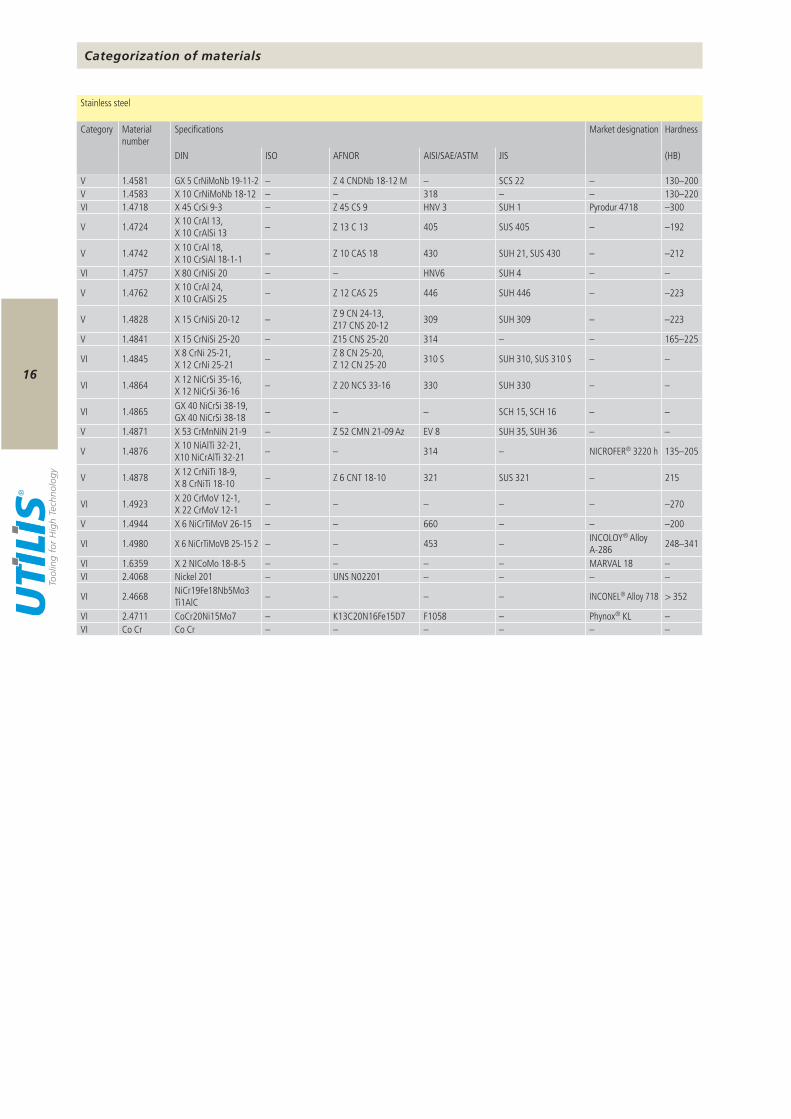
V 1.4581 GX 5 CrNiMoNb 19-11-2 – Z 4 CNDNb 18-12 M – SCS 22 – 130–200V 1.4583 X 10 CrNiMoNb 18-12 – – 318 – – 130–220VI 1.4718 X 45 CrSi 9-3 – Z 45 CS 9 HNV 3 SUH 1 Pyrodur 4718 –300
V 1.4724 X 10 CrAl 13, X 10 CrAlSi 13 – Z 13 C 13 405 SUS 405 – –192
V 1.4742 X 10 CrAl 18, X 10 CrSiAl 18-1-1 – Z 10 CAS 18 430 SUH 21, SUS 430 – –212
VI 1.4757 X 80 CrNiSi 20 – – HNV6 SUH 4 – –
V 1.4762 X 10 CrAl 24, X 10 CrAlSi 25 – Z 12 CAS 25 446 SUH 446 – –223
V 1.4828 X 15 CrNiSi 20-12 – Z 9 CN 24-13, Z17 CNS 20-12 309 SUH 309 – –223
V 1.4841 X 15 CrNiSi 25-20 – Z15 CNS 25-20 314 – – 165–225
VI 1.4845 X 8 CrNi 25-21, X 12 CrNi 25-21 – Z 8 CN 25-20,
Z 12 CN 25-20 310 S SUH 310, SUS 310 S – –
VI 1.4864 X 12 NiCrSi 35-16, X 12 NiCrSi 36-16 – Z 20 NCS 33-16 330 SUH 330 – –
VI 1.4865 GX 40 NiCrSi 38-19, GX 40 NiCrSi 38-18 – – – SCH 15, SCH 16 – –
V 1.4871 X 53 CrMnNiN 21-9 – Z 52 CMN 21-09 Az EV 8 SUH 35, SUH 36 – –
V 1.4876 X 10 NiAlTi 32-21, X10 NiCrAlTi 32-21 – – 314 – NICROFER® 3220 h 135–205
V 1.4878 X 12 CrNiTi 18-9, X 8 CrNiTi 18-10 – Z 6 CNT 18-10 321 SUS 321 – 215
VI 1.4923 X 20 CrMoV 12-1, X 22 CrMoV 12-1 – – – – – –270
V 1.4944 X 6 NiCrTiMoV 26-15 – – 660 – – –200
VI 1.4980 X 6 NiCrTiMoVB 25-15 2 – – 453 – INCOLOY® Alloy A-286 248–341
VI 1.6359 X 2 NICoMo 18-8-5 – – – – MARVAL 18 –VI 2.4068 Nickel 201 – UNS N02201 – – – –
VI 2.4668 NiCr19Fe18Nb5Mo3 Ti1AlC – – – – INCONEL® Alloy 718 > 352
VI 2.4711 CoCr20Ni15Mo7 – K13C20N16Fe15D7 F1058 – Phynox® KL –VI Co Cr Co Cr – – – – – –
Categorization of materials
Stainless steel
Category Material number
Specifications Market designation Hardness
17
DIN ISO AFNOR AISI/SAE/ASTM JIS (HB)
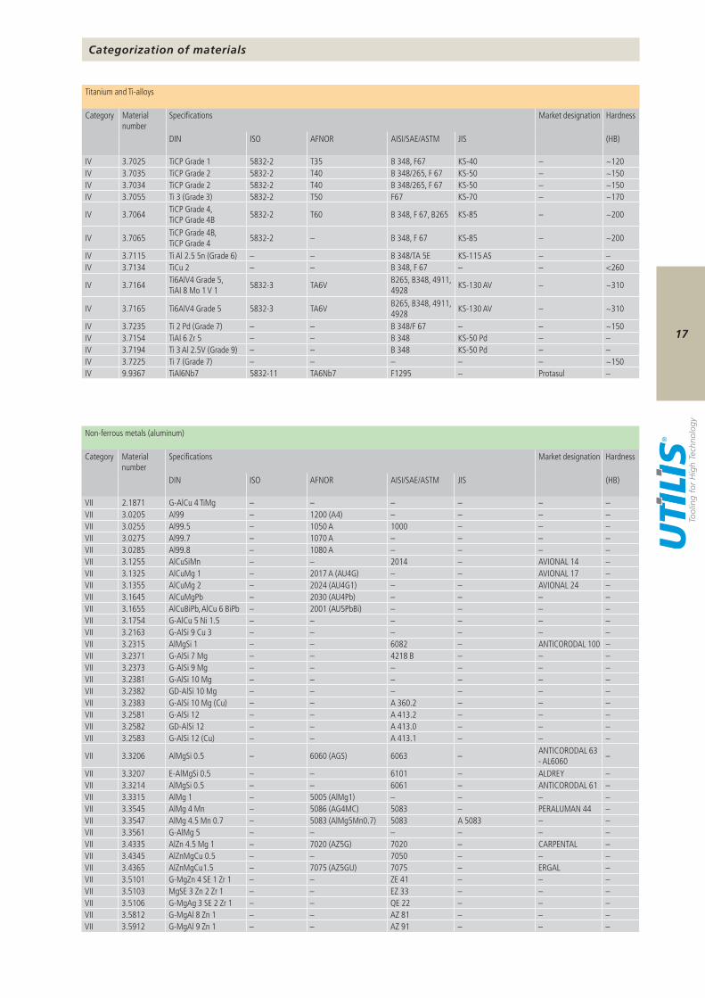
IV 3.7025 TiCP Grade 1 5832-2 T35 B 348, F67 KS-40 – ~120IV 3.7035 TiCP Grade 2 5832-2 T40 B 348/265, F 67 KS-50 – ~150IV 3.7034 TiCP Grade 2 5832-2 T40 B 348/265, F 67 KS-50 – ~150IV 3.7055 Ti 3 (Grade 3) 5832-2 T50 F67 KS-70 – ~170
IV 3.7064 TiCP Grade 4, TiCP Grade 4B 5832-2 T60 B 348, F 67, B265 KS-85 – ~200
IV 3.7065 TiCP Grade 4B, TiCP Grade 4 5832-2 – B 348, F 67 KS-85 – ~200
IV 3.7115 Ti Al 2.5 5n (Grade 6) – – B 348/TA 5E KS-115 AS – –IV 3.7134 TiCu 2 – – B 348, F 67 – – <260
IV 3.7164 Ti6AlV4 Grade 5, TiAI 8 Mo 1 V 1 5832-3 TA6V B265, B348, 4911,
4928 KS-130 AV – ~310
IV 3.7165 Ti6AlV4 Grade 5 5832-3 TA6V B265, B348, 4911, 4928 KS-130 AV – ~310
IV 3.7235 Ti 2 Pd (Grade 7) – – B 348/F 67 – – ~150IV 3.7154 TiAl 6 Zr 5 – – B 348 KS-50 Pd – –IV 3.7194 Ti 3 Al 2.5V (Grade 9) – – B 348 KS-50 Pd – –IV 3.7225 Ti 7 (Grade 7) – – – – – ~150IV 9.9367 TiAl6Nb7 5832-11 TA6Nb7 F1295 – Protasul –
DIN ISO AFNOR AISI/SAE/ASTM JIS (HB)
VII 2.1871 G-AlCu 4 TiMg – – – – – –VII 3.0205 Al99 – 1200 (A4) – – – –VII 3.0255 Al99.5 – 1050 A 1000 – – –VII 3.0275 Al99.7 – 1070 A – – – –VII 3.0285 Al99.8 – 1080 A – – – –VII 3.1255 AlCuSiMn – – 2014 – AVIONAL 14 –VII 3.1325 AlCuMg 1 – 2017 A (AU4G) – – AVIONAL 17 –VII 3.1355 AlCuMg 2 – 2024 (AU4G1) – – AVIONAL 24 –VII 3.1645 AlCuMgPb – 2030 (AU4Pb) – – – –VII 3.1655 AlCuBiPb, AlCu 6 BiPb – 2001 (AU5PbBi) – – – –VII 3.1754 G-AlCu 5 Ni 1.5 – – – – – –VII 3.2163 G-AlSi 9 Cu 3 – – – – – –VII 3.2315 AlMgSi 1 – – 6082 – ANTICORODAL 100 –VII 3.2371 G-AlSi 7 Mg – – 4218 B – – –VII 3.2373 G-AlSi 9 Mg – – – – – –VII 3.2381 G-AlSi 10 Mg – – – – – –VII 3.2382 GD-AlSi 10 Mg – – – – – –VII 3.2383 G-AlSi 10 Mg (Cu) – – A 360.2 – – –VII 3.2581 G-AlSi 12 – – A 413.2 – – –VII 3.2582 GD-AlSi 12 – – A 413.0 – – –VII 3.2583 G-AlSi 12 (Cu) – – A 413.1 – – –
VII 3.3206 AlMgSi 0.5 – 6060 (AGS) 6063 – ANTICORODAL 63 - AL6060 –
VII 3.3207 E-AlMgSi 0.5 – – 6101 – ALDREY –VII 3.3214 AlMgSi 0.5 – – 6061 – ANTICORODAL 61 –VII 3.3315 AlMg 1 – 5005 (AlMg1) – – – –VII 3.3545 AlMg 4 Mn – 5086 (AG4MC) 5083 – PERALUMAN 44 –VII 3.3547 AlMg 4.5 Mn 0.7 – 5083 (AlMg5Mn0.7) 5083 A 5083 – –VII 3.3561 G-AlMg 5 – – – – – –VII 3.4335 AlZn 4.5 Mg 1 – 7020 (AZ5G) 7020 – CARPENTAL –VII 3.4345 AlZnMgCu 0.5 – – 7050 – – –VII 3.4365 AlZnMgCu1.5 – 7075 (AZ5GU) 7075 – ERGAL –VII 3.5101 G-MgZn 4 SE 1 Zr 1 – – ZE 41 – – –VII 3.5103 MgSE 3 Zn 2 Zr 1 – – EZ 33 – – –VII 3.5106 G-MgAg 3 SE 2 Zr 1 – – QE 22 – – –VII 3.5812 G-MgAl 8 Zn 1 – – AZ 81 – – –VII 3.5912 G-MgAl 9 Zn 1 – – AZ 91 – – –
Categorization of materials
Titanium and Ti-alloys
Category Material number
Specifications Market designation Hardness
Non-ferrous metals (aluminum)
Category Material number
Specifications Market designation Hardness
18
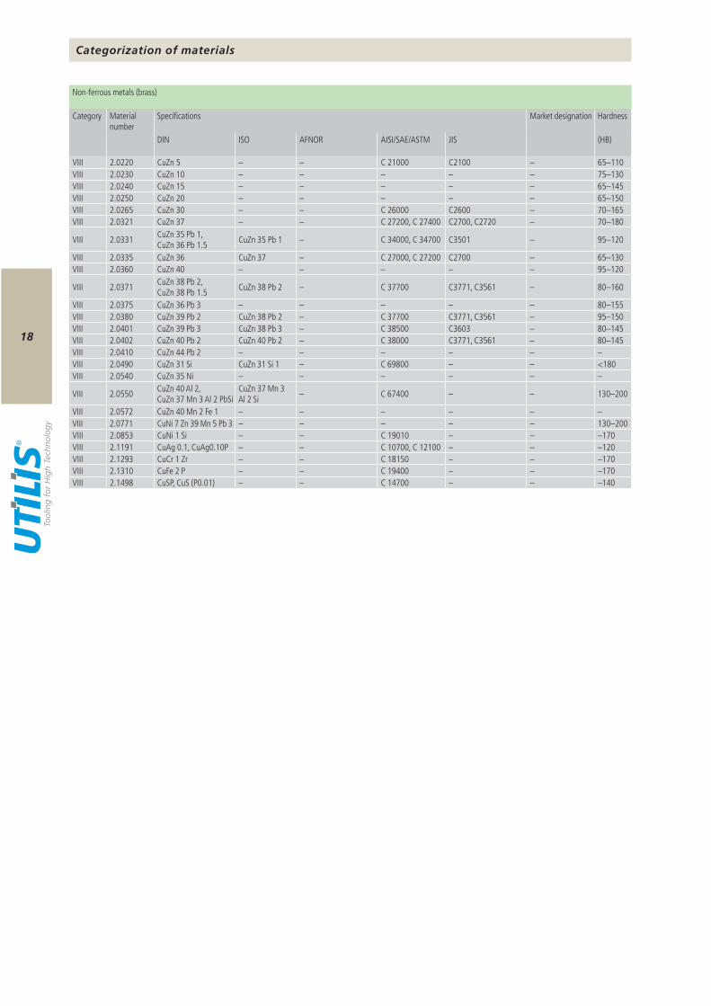
DIN ISO AFNOR AISI/SAE/ASTM JIS (HB)
VIII 2.0220 CuZn 5 – – C 21000 C2100 – 65–110VIII 2.0230 CuZn 10 – – – – – 75–130VIII 2.0240 CuZn 15 – – – – – 65–145VIII 2.0250 CuZn 20 – – – – – 65–150VIII 2.0265 CuZn 30 – – C 26000 C2600 – 70–165VIII 2.0321 CuZn 37 – – C 27200, C 27400 C2700, C2720 – 70–180
VIII 2.0331 CuZn 35 Pb 1, CuZn 36 Pb 1.5 CuZn 35 Pb 1 – C 34000, C 34700 C3501 – 95–120
VIII 2.0335 CuZn 36 CuZn 37 – C 27000, C 27200 C2700 – 65–130VIII 2.0360 CuZn 40 – – – – – 95–120
VIII 2.0371 CuZn 38 Pb 2, CuZn 38 Pb 1.5 CuZn 38 Pb 2 – C 37700 C3771, C3561 – 80–160
VIII 2.0375 CuZn 36 Pb 3 – – – – – 80–155VIII 2.0380 CuZn 39 Pb 2 CuZn 38 Pb 2 – C 37700 C3771, C3561 – 95–150VIII 2.0401 CuZn 39 Pb 3 CuZn 38 Pb 3 – C 38500 C3603 – 80–145VIII 2.0402 CuZn 40 Pb 2 CuZn 40 Pb 2 – C 38000 C3771, C3561 – 80–145VIII 2.0410 CuZn 44 Pb 2 – – – – – –VIII 2.0490 CuZn 31 Si CuZn 31 Si 1 – C 69800 – – <180VIII 2.0540 CuZn 35 Ni – – – – – –
VIII 2.0550 CuZn 40 Al 2, CuZn 37 Mn 3 Al 2 PbSi
CuZn 37 Mn 3 Al 2 Si – C 67400 – – 130–200
VIII 2.0572 CuZn 40 Mn 2 Fe 1 – – – – – –VIII 2.0771 CuNi 7 Zn 39 Mn 5 Pb 3 – – – – – 130–200VIII 2.0853 CuNi 1 Si – – C 19010 – – –170VIII 2.1191 CuAg 0.1, CuAg0.10P – – C 10700, C 12100 – – –120VIII 2.1293 CuCr 1 Zr – – C 18150 – – –170VIII 2.1310 CuFe 2 P – – C 19400 – – –170VIII 2.1498 CuSP, CuS (P0.01) – – C 14700 – – –140
Categorization of materials
Non-ferrous metals (brass)
Category Material number
Specifications Market designation Hardness
19
UHM 10 K 10 / M 10 – – – – – –UHM 10 HX K 10 / M 10 –UHM 10 MZ P 15 / M 10 – – – – – –UHM 20 K 20 / M 20 – – –UHM 20 HPX P 20–40 / M 20–40 – – –UHM 20 HX K 20 / M 20 –UHM 20 MZ P 25 / M 20 – – – –UHM 30 K 30 / M 20 –UHM 30 HX K 30 / M 20 – –UHM 30 MZ P 35 / M 35 – – – – –UHM 30 SX K 30 / M 20 – – – –
UCM 10 P 15 / K 10 / M 10 – – – –UCM 10 HX P 15 / K 10 / M 10 – – – –UCM 10 MZ P 10 / K 05 / M 10 – – – –
HSS P 40–50 / M 40–50 – –HSS HX P 40–50 / M 40–50 –HSS SX P 40–50 / M 40–50 –
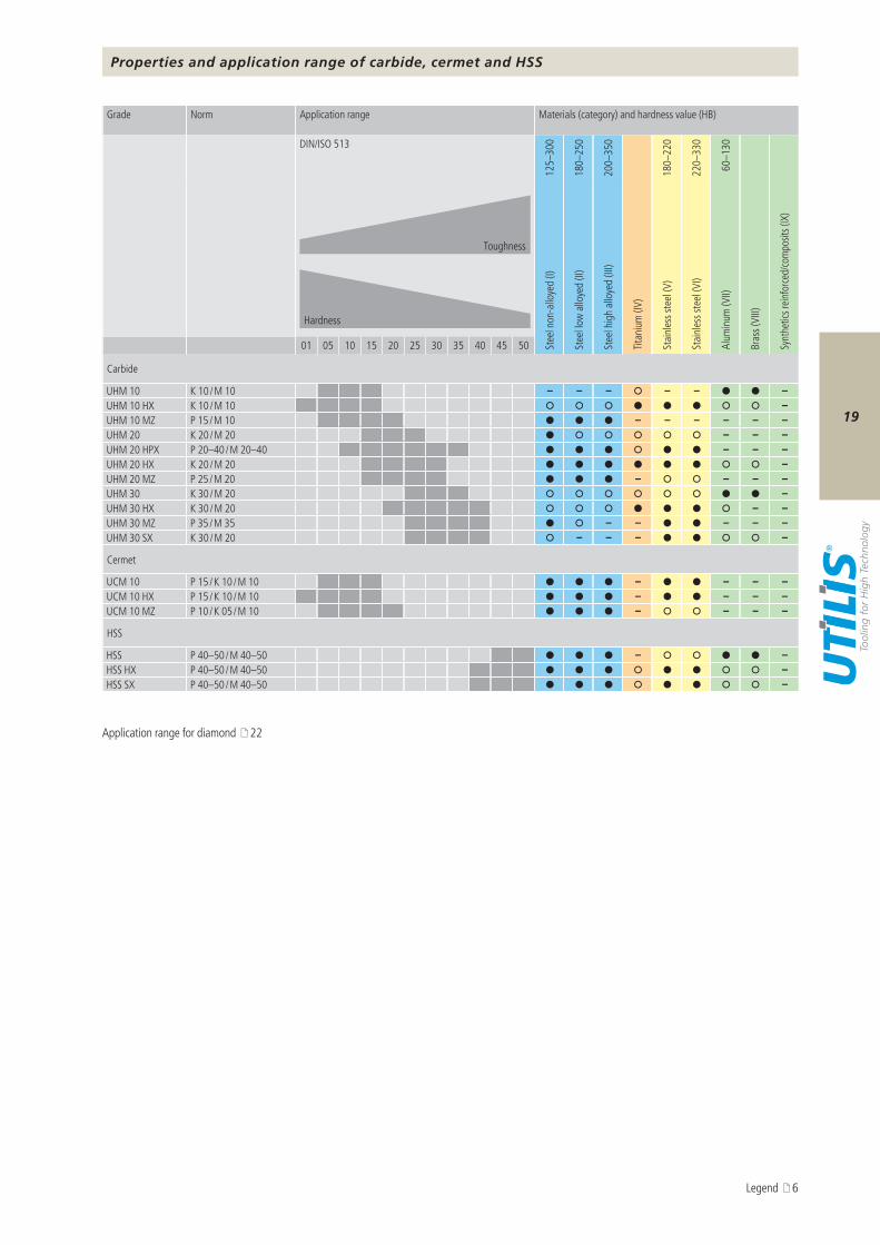
Properties and application range of carbide, cermet and HSS
Grade Norm Application range Materials (category) and hardness value (HB)
DIN/ISO 513
125–
300
180–
250
200–
350
180–
220
220–
330
60–1
30
Toughness
Hardness
Stee
l non
-allo
yed
(I)
Stee
l low
allo
yed
(II)
Stee
l hig
h al
loye
d (II
I)
Titan
ium
(IV)
Stai
nles
s ste
el (V
)
Stai
nles
s ste
el (V
I)
Alum
inum
(VII)
Bras
s (VI
II)
Synt
hetic
s rein
forc
ed/co
mpo
sits (
IX)
01 05 10 15 20 25 30 35 40 45 50
Carbide
Cermet
HSS
Legend 6
Application range for diamond 22
20
r >0.002r <0.002
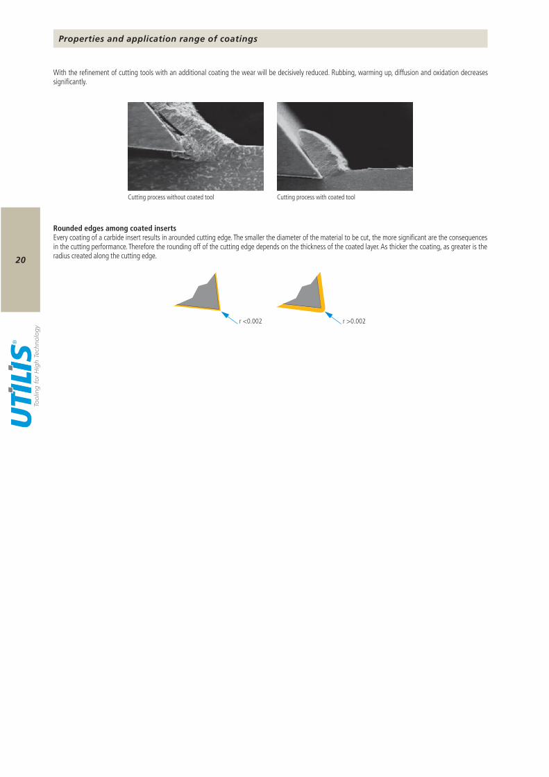
Properties and application range of coatings
With the refinement of cutting tools with an additional coating the wear will be decisively reduced. Rubbing, warming up, diffusion and oxidation decreases significantly.
Cutting process without coated tool Cutting process with coated tool
Rounded edges among coated insertsEvery coating of a carbide insert results in arounded cutting edge. The smaller the diameter of the material to be cut, the more significant are the consequences in the cutting performance. Therefore the rounding off of the cutting edge depends on the thickness of the coated layer. As thicker the coating, as greater is the radius created along the cutting edge.
21
HX HPX MZ SX BX HX-A HX-F TX+ DX-T DX-HC
TiAIN / AlTiN
TiAIN / AlTiN
TiN / TiAIN TiN TiCN AlCrN AlCrN TiSiN Diamond
DLCDiamond
Ta-C
PVD PVD CVD PVD PVD PVD PVD PVD PVD PVD
(I) – – –
(II) – – –
(III) – – –
(IV) – – – –
(V) – –
(VI) – –
(VII) – – – – –
(VIII) – – – – –
(IX) – – – – – –
> 70 HRC – – – – – – – – –
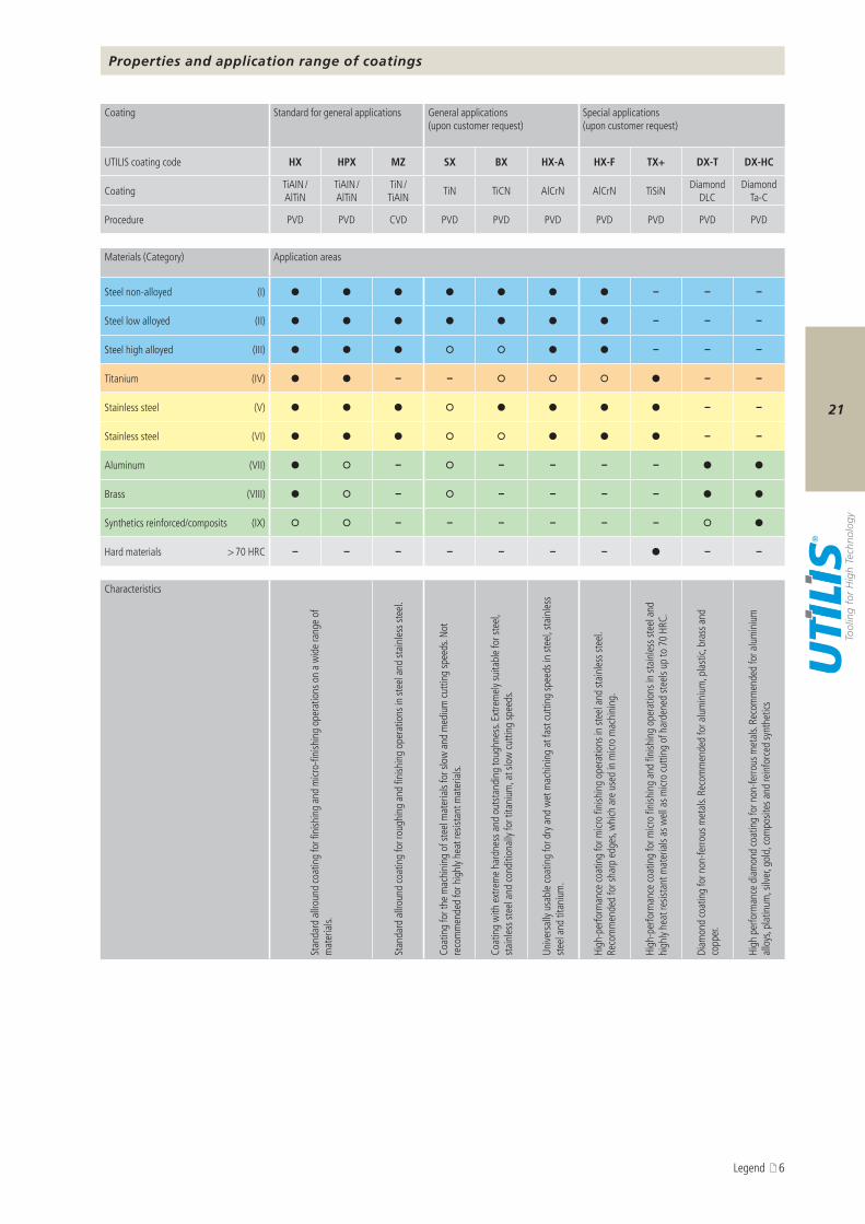
Properties and application range of coatings
Legend 6
Coating Standard for general applications General applications(upon customer request)
Special applications(upon customer request)
UTILIS coating code
Coating
Procedure
Materials (Category) Application areas
Steel non-alloyed
Steel low alloyed
Steel high alloyed
Titanium
Stainless steel
Stainless steel
Aluminum
Brass
Synthetics reinforced/composits
Hard materials
Characteristics
Stan
dard
allr
ound
coat
ing
for f
inish
ing
and
micr
o-fin
ishin
g op
erat
ions
on
a w
ide
rang
e of
m
ater
ials.
Stan
dard
allr
ound
coat
ing
for r
ough
ing
and
finish
ing
oper
atio
ns in
stee
l and
stai
nles
s ste
el.
Coat
ing
for t
he m
achi
ning
of s
teel
mat
eria
ls fo
r slo
w a
nd m
ediu
m cu
tting
spee
ds. N
ot
reco
mm
ende
d fo
r hig
hly h
eat r
esist
ant m
ater
ials.
Coat
ing
with
ext
rem
e ha
rdne
ss a
nd o
utst
andi
ng to
ughn
ess.
Extre
mel
y sui
tabl
e fo
r ste
el,
stai
nles
s ste
el a
nd co
nditi
onal
ly fo
r tita
nium
, at s
low
cutti
ng sp
eeds
.
Unive
rsal
ly us
able
coat
ing
for d
ry a
nd w
et m
achi
ning
at f
ast c
uttin
g sp
eeds
in st
eel, s
tain
less
st
eel a
nd ti
tani
um.
High
-per
form
ance
coat
ing
for m
icro
finish
ing
oper
atio
ns in
stee
l and
stai
nles
s ste
el.
Reco
mm
ende
d fo
r sha
rp e
dges
, whi
ch a
re u
sed
in m
icro
mac
hini
ng.
High
-per
form
ance
coat
ing
for m
icro
finish
ing
and
finish
ing
oper
atio
ns in
stai
nles
s ste
el a
nd
high
ly he
at re
sista
nt m
ater
ials
as w
ell a
s micr
o cu
tting
of h
arde
ned
stee
ls up
to 7
0 HR
C.
Diam
ond
coat
ing
for n
on-fe
rrous
met
als.
Reco
mm
ende
d fo
r alu
min
ium
, pla
stic,
bra
ss a
nd
copp
er.
High
per
form
ance
dia
mon
d co
atin
g fo
r non
-ferro
us m
etal
s. Re
com
men
ded
for a
lum
iniu
m
allo
ys, p
latin
um, s
ilver,
gol
d, co
mpo
sites
and
rein
forc
ed sy
nthe
tics
22
UPCD15
UCVD08
UPCD20
Properties and application range for diamond
The exceptional hardness of diamonds in the various tool versions enables much higher cutting parameters to be achieved compared when conventional cutting materials are used.In addition to traditional grinding and erosion machining, the use of high tech lasers not only produces top quality cutting edges, but also enables 3D chip removal geometries to be obtained.
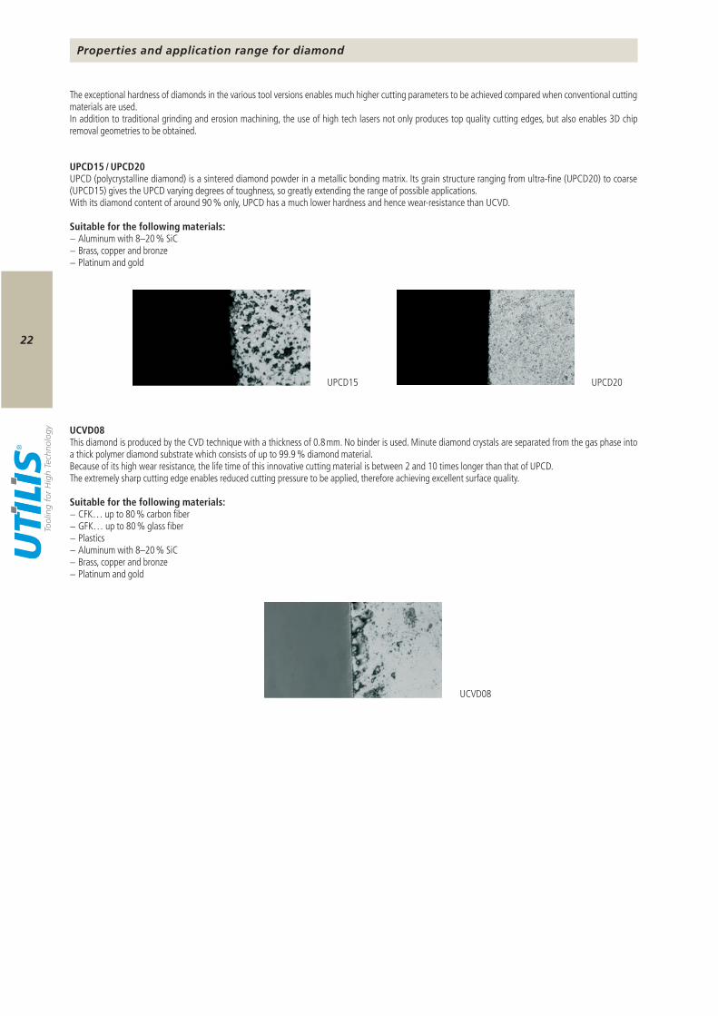
UPCD15 / UPCD20UPCD (polycrystalline diamond) is a sintered diamond powder in a metallic bonding matrix. Its grain structure ranging from ultra-fine (UPCD20) to coarse (UPCD15) gives the UPCD varying degrees of toughness, so greatly extending the range of possible applications.With its diamond content of around 90 % only, UPCD has a much lower hardness and hence wear-resistance than UCVD.
Suitable for the following materials:− Aluminum with 8–20 % SiC− Brass, copper and bronze− Platinum and gold
UCVD08This diamond is produced by the CVD technique with a thickness of 0.8 mm. No binder is used. Minute diamond crystals are separated from the gas phase into a thick polymer diamond substrate which consists of up to 99.9 % diamond material.Because of its high wear resistance, the life time of this innovative cutting material is between 2 and 10 times longer than that of UPCD.The extremely sharp cutting edge enables reduced cutting pressure to be applied, therefore achieving excellent surface quality.
Suitable for the following materials:− CFK… up to 80 % carbon fiber− GFK… up to 80 % glass fiber− Plastics− Aluminum with 8–20 % SiC− Brass, copper and bronze− Platinum and gold
23
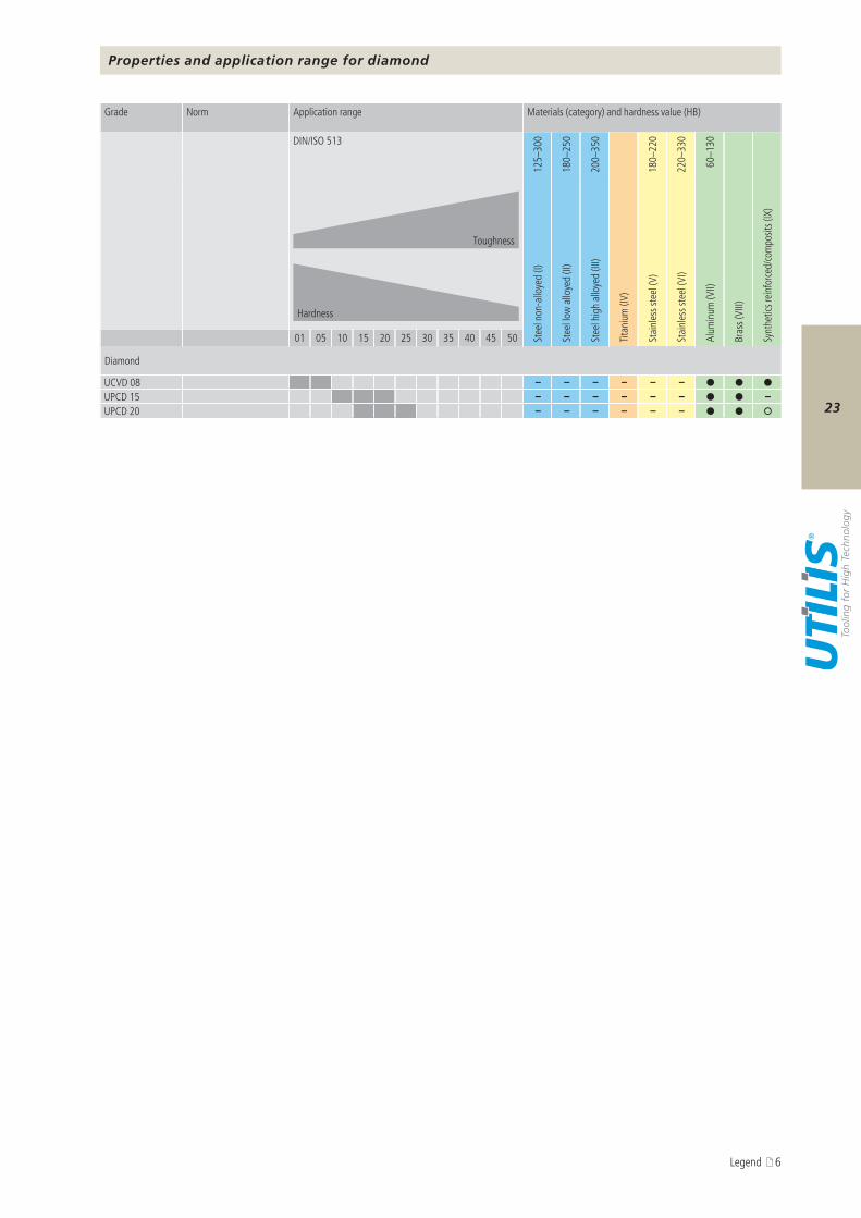
UCVD 08 – – – – – –UPCD 15 – – – – – – –UPCD 20 – – – – – –
Properties and application range for diamond
Grade Norm Application range Materials (category) and hardness value (HB)
DIN/ISO 513
125–
300
180–
250
200–
350
180–
220
220–
330
60–1
30
Toughness
Hardness
Stee
l non
-allo
yed
(I)
Stee
l low
allo
yed
(II)
Stee
l hig
h al
loye
d (II
I)
Titan
ium
(IV)
Stai
nles
s ste
el (V
)
Stai
nles
s ste
el (V
I)
Alum
inum
(VII)
Bras
s (VI
II)
Synt
hetic
s rein
forc
ed/co
mpo
sits (
IX)
01 05 10 15 20 25 30 35 40 45 50
Diamond
Legend 6
24
250
200
150
100
50
00.04 0.08 0.12 0.16 0.20 0.24 0.28
– r = 0.05 mm – r = 0.10 mm – r = 0.20 mm – r = 0.40 mm – r = 0.80 mm
R t (μ
m)
f (mm)
f
r r
f
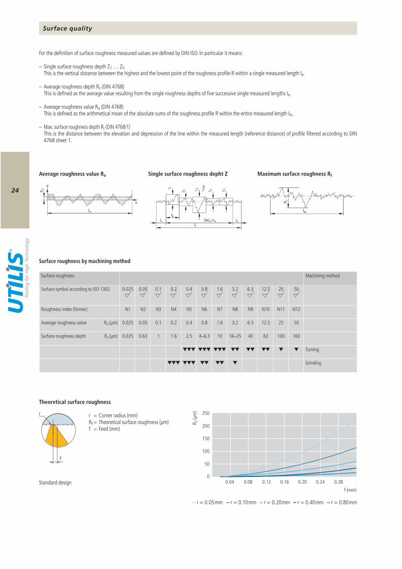
For the definition of surface roughness measured values are defined by DIN-ISO. In particular it means:
– Single surface roughness depth Z1 … Z5 This is the vertical distance between the highest and the lowest point of the rough ness profile R within a single measured length le.
– Average roughness depth Rz (DIN 4768) This is defined as the average value resulting from the single roughness depths of five successive single measured lengths Ie.
– Average roughness value Ra (DIN 4768) This is defined as the arithmetical mean of the absolute sums of the roughness profile R within the entire measured length Im.
– Max. surface roughness depth Rt (DIN 4768/1) This is the distance between the elevation and depression of the line within the measured length (reference distance) of profile filtered according to DIN
4768 sheet 1.
Surface roughness by machining method
r = Corner radius (mm)Rt = Theoretical surface roughness (µm)f = Feed (mm)
Theoretical surface roughness
Maximum surface roughness RtAverage roughness value Ra Single surface roughness depht Z
Standard design
Surface roughness Machining method
Surface symbol according to ISO 1302 0.025 0.05 0.1 0.2 0.4 0.8 1.6 3.2 6.3 12.5 25 50
Roughness index (former) N1 N2 N3 N4 N5 N6 N7 N8 N9 N10 N11 N12
Average roughness value Ra (µm) 0.025 0.05 0.1 0.2 0.4 0.8 1.6 3.2 6.3 12.5 25 50
Surface roughness depth Rz (µm) 0.025 0.63 1 1.6 2.5 4–6.3 10 16–25 40 63 100 160
Turning
Grinding
Surface quality
25
Halter | Porte-outil | Holder 93°Eckenradius | Rayon | Corner radius 0.8 mm
Halter | Porte-outil | Holder 93°Eckenradius | Rayon | Corner radius 0.8 mmMultidec®-Top-Schneide | Plaquette Multidec®-Top | Multidec®-Top insert
ap ap
93° 93°
f 2×f
N6Ra 0.8 μmRz (Rt) 6.3 μm
N6Ra 0.8 μmRz (Rt) 6.3 μm
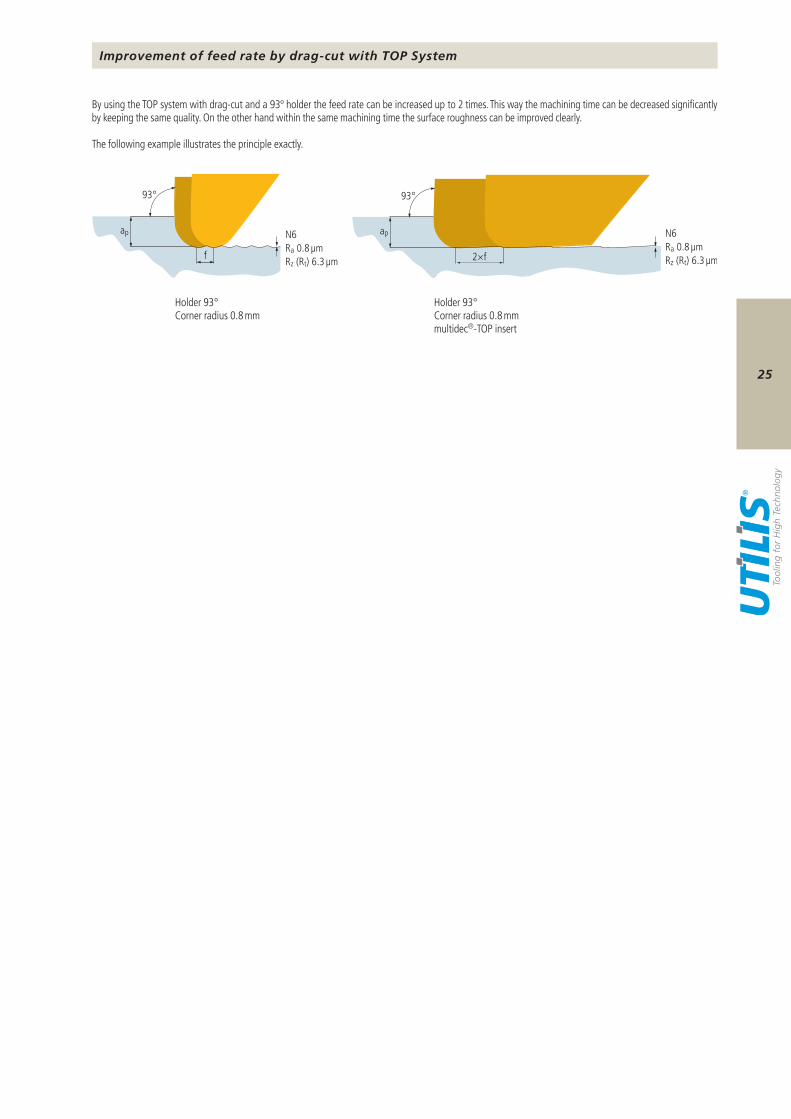
By using the TOP system with drag-cut and a 93º holder the feed rate can be increased up to 2 times. This way the machining time can be decreased significantly by keeping the same quality. On the other hand within the same machining time the surface roughness can be improved clearly.
The following example illustrates the principle exactly.
Holder 93°Corner radius 0.8 mm
Holder 93°Corner radius 0.8 mmmultidec®-TOP insert
Improvement of feed rate by drag-cut with TOP System
26
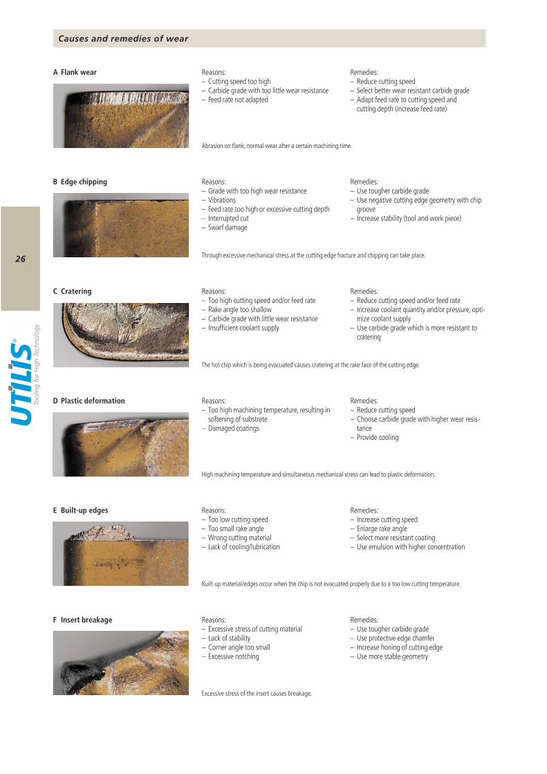
Causes and remedies of wear
Abrasion on flank, normal wear after a certain machining time.
Through excessive mechanical stress at the cutting edge fracture and chipping can take place.
Remedies:– Use tougher carbide grade– Use negative cutting edge geometry with chip
groove– Increase stability (tool and work piece)
Reasons:– Grade with too high wear resistance– Vibrations– Feed rate too high or excessive cutting depth– Interrupted cut– Swarf damage
B Edge chipping
The hot chip which is being evacuated causes cratering at the rake face of the cutting edge.
Remedies:– Reduce cutting speed and/or feed rate– Increase coolant quantity and/or pressure, opti-
mize coolant supply– Use carbide grade which is more resistant to
cratering
Reasons:– Too high cutting speed and/or feed rate– Rake angle too shallow– Carbide grade with little wear resistance– Insufficient coolant supply
C Cratering
Remedies:– Reduce cutting speed– Select better wear resistant carbide grade– Adapt feed rate to cutting speed and
cutting depth (increase feed rate)
Reasons:– Cutting speed too high– Carbide grade with too little wear resistance– Feed rate not adapted
A Flank wear
High machining temperature and simultaneous mechanical stress can lead to plastic deformation.
Built-up material/edges occur when the chip is not evacuated properly due to a too low cutting temperature.
Remedies:– Increase cutting speed– Enlarge rake angle– Select more resistant coating– Use emulsion with higher concentration
Reasons:– Too low cutting speed– Too small rake angle– Wrong cutting material– Lack of cooling/lubrication
E Built-up edges
Excessive stress of the insert causes breakage.
Remedies:– Use tougher carbide grade– Use protective edge chamfer– Increase honing of cutting edge– Use more stable geometry
Reasons:– Excessive stress of cutting material– Lack of stability– Corner angle too small– Excessive notching
F Insert breakage
Remedies:– Reduce cutting speed– Choose carbide grade with higher wear resis-
tance– Provide cooling
Reasons:– Too high machining temperature, re sulting in
softening of substrate– Damaged coatings
D Plastic deformation
27
A*
B*
C*
D*
E*
F*
vc
ap
f
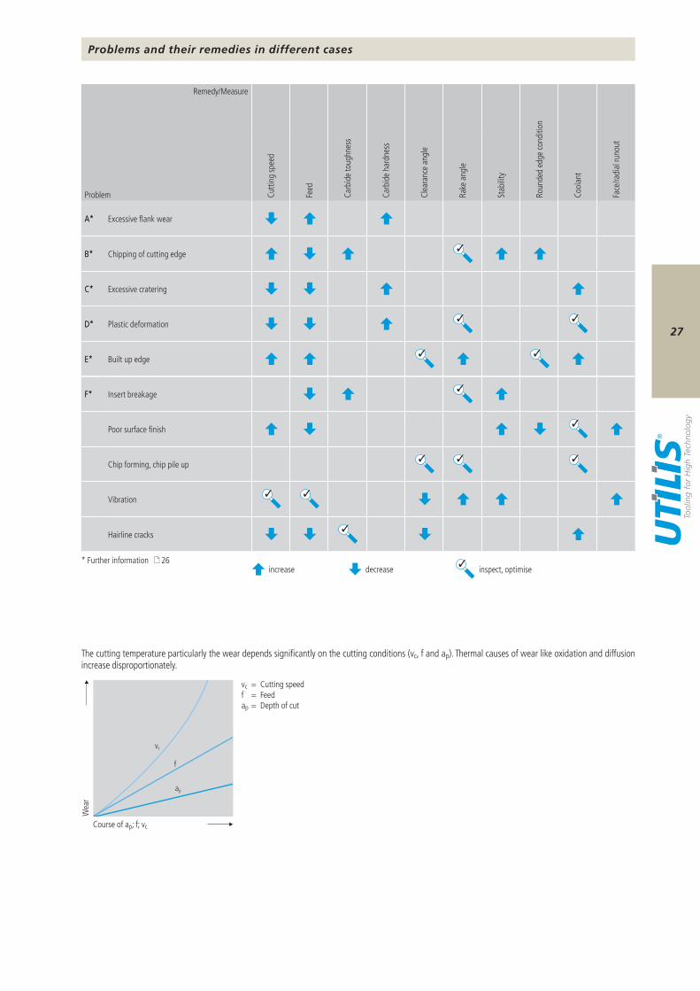
Problems and their remedies in different cases
The cutting temperature particularly the wear depends significantly on the cutting conditions (vc, f and ap). Thermal causes of wear like oxidation and diffusion increase disproportionately.
Remedy/Measure
Cutti
ng sp
eed
Feed
Carb
ide
toug
hnes
s
Carb
ide
hard
ness
Clea
ranc
e an
gle
Rake
ang
le
Stab
ility
Roun
ded
edge
cond
ition
Cool
ant
Face
/radi
al ru
nout
Problem
A* Excessive flank wear
B* Chipping of cutting edge
C* Excessive cratering
D* Plastic deformation
E* Built up edge
F* Insert breakage
Poor surface finish
Chip forming, chip pile up
Vibration
Hairline cracks
Course of ap; f; vc
Wea
r
vc = Cutting speedf = Feedap = Depth of cut
* Further information 26increase decrease inspect, optimise
28
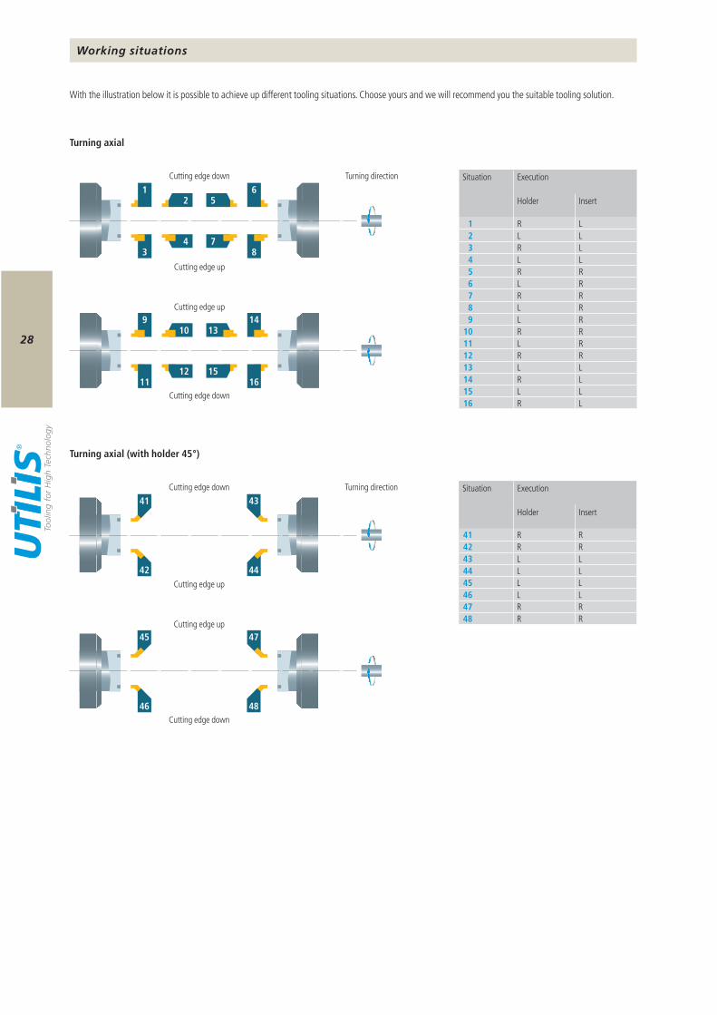
1 R L2 L L3 R L4 L L5 R R6 L R7 R R8 L R9 L R
10 R R11 L R12 R R13 L L14 R L15 L L16 R L
41 R R42 R R43 L L44 L L45 L L46 L L47 R R48 R R
1
3
6
8
2 5
4 7
41
42
43
44
9
11
14
16
10 13
12 15
45
46
47
48
With the illustration below it is possible to achieve up different tooling situations. Choose yours and we will recommend you the suitable tooling solution.
Turning axial
Turning axial (with holder 45°)
Situation Execution
Holder Insert
Situation Execution
Holder Insert
Working situations
Cutting edge down
Cutting edge down
Cutting edge down
Cutting edge down
Turning direction
Turning direction
Cutting edge up
Cutting edge up
Cutting edge up
Cutting edge up
29
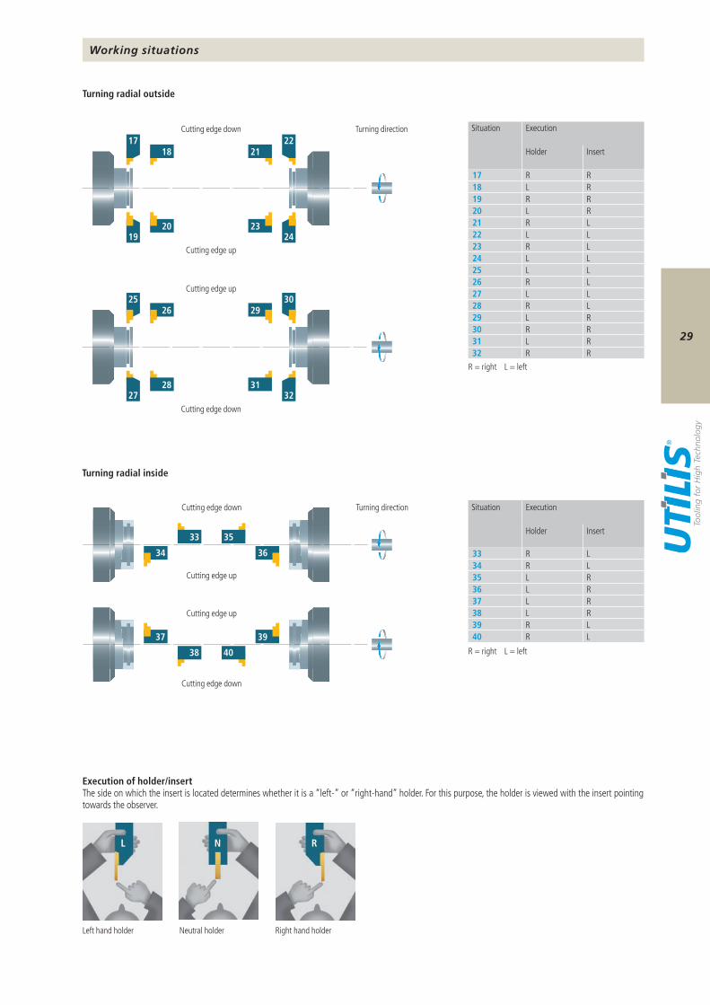
33 R L34 R L35 L R36 L R37 L R38 L R39 R L40 R L
17 R R18 L R19 R R20 L R21 R L22 L L23 R L24 L L25 L L26 R L27 L L28 R L29 L R30 R R31 L R32 R R
18
20
21
23
17 22
19 24
26
28
29
31
25 30
27 32
33 35
34 36
38 40
37 39
R N L
Turning radial outside
Turning radial inside
Situation Execution
Holder Insert
Situation Execution
Holder Insert
R = right L = left
R = right L = left
Execution of holder/insertThe side on which the insert is located determines whether it is a “left-” or “right-hand” holder. For this purpose, the holder is viewed with the insert pointing towards the observer.
Working situations
Cutting edge down
Cutting edge down Turning direction
Cutting edge up
Cutting edge up
Cutting edge down
Cutting edge down Turning direction
Cutting edge up
Cutting edge up
Left hand holder Neutral holder Right hand holder
multidec®-MULTITASK
30
0
0
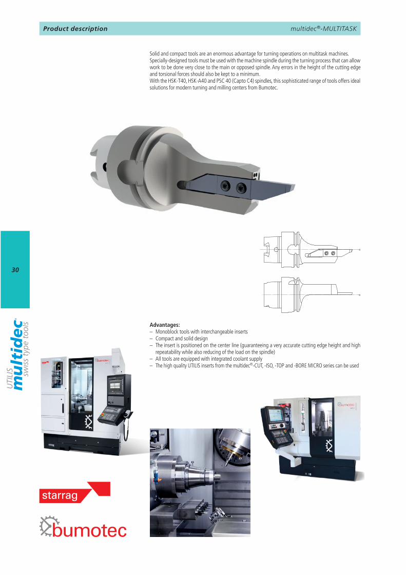
Product description
Solid and compact tools are an enormous advantage for turning operations on multitask machines.Specially-designed tools must be used with the machine spindle during the turning process that can allow work to be done very close to the main or opposed spindle. Any errors in the height of the cutting edge and torsional forces should also be kept to a minimum.With the HSK-T40, HSK-A40 and PSC 40 (Capto C4) spindles, this sophisticated range of tools offers ideal solutions for modern turning and milling centers from Bumotec.
Advantages:– Monoblock tools with interchangeable inserts– Compact and solid design– The insert is positioned on the center line (guaranteeing a very accurate cutting edge height and high
repeatability while also reducing of the load on the spindle)– All tools are equipped with integrated coolant supply– The high quality UTILIS inserts from the multidec®-CUT, -ISO, -TOP and -BORE MICRO series can be used
multidec®-MULTITASK
31
9
32 38 39 45 46
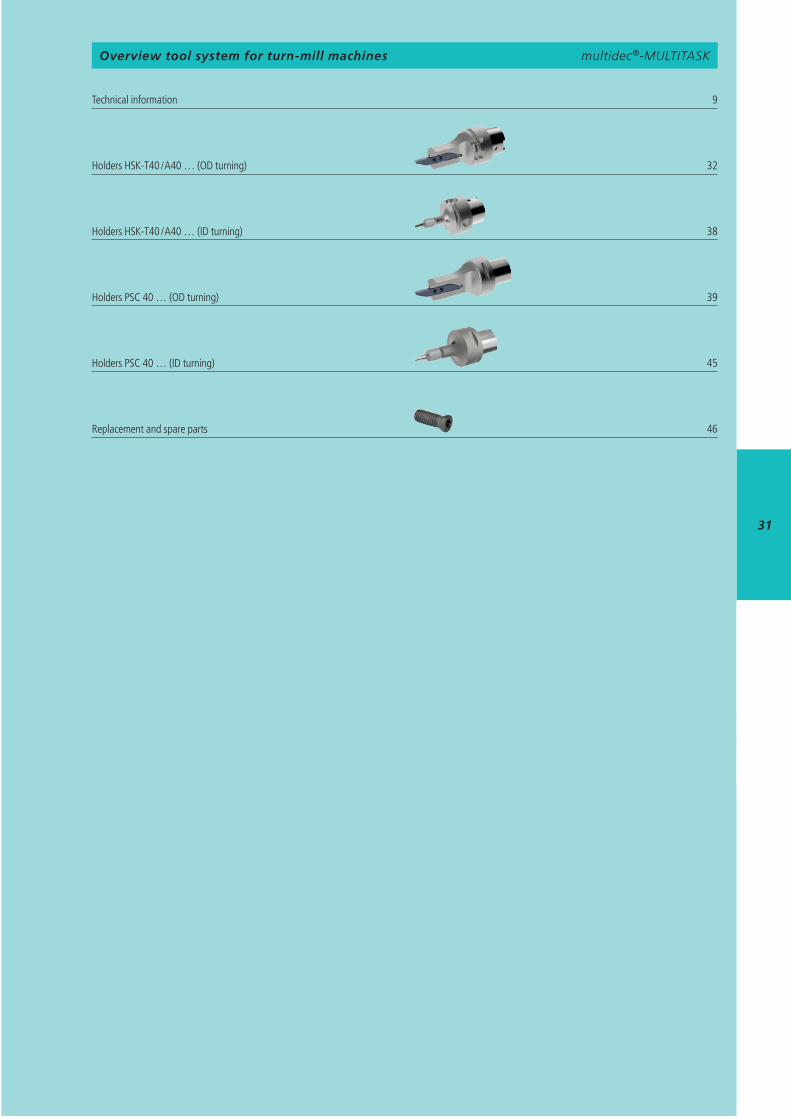
multidec®-MULTITASKOverview tool system for turn-mill machines
Technical information Holders HSK-T40 / A40 … (OD turning) Holders HSK-T40 / A40 … (ID turning) Holders PSC 40 … (OD turning) Holders PSC 40 … (ID turning) Replacement and spare parts
multidec®-MULTITASK
32
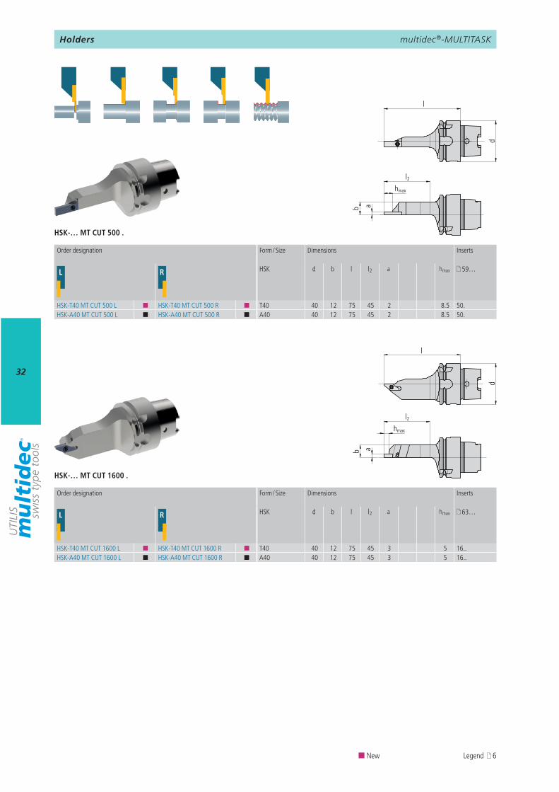
L R HSK d b l l2 a hmax 59…
HSK-T40 MT CUT 500 L ¢ HSK-T40 MT CUT 500 R ¢ T40 40 12 75 45 2 8.5 50.HSK-A40 MT CUT 500 L ¢ HSK-A40 MT CUT 500 R ¢ A40 40 12 75 45 2 8.5 50.
L R HSK d b l l2 a hmax 63…
HSK-T40 MT CUT 1600 L ¢ HSK-T40 MT CUT 1600 R ¢ T40 40 12 75 45 3 5 16..HSK-A40 MT CUT 1600 L ¢ HSK-A40 MT CUT 1600 R ¢ A40 40 12 75 45 3 5 16..
HSK-… MT CUT 500 .
HSK-… MT CUT 1600 .
d
l
b a
hmax
l2
d
lb a
hmax
l2
Order designation Form / Size Dimensions Inserts
Order designation Form / Size Dimensions Inserts
¢ New Legend 6
Holders
multidec®-MULTITASK
33
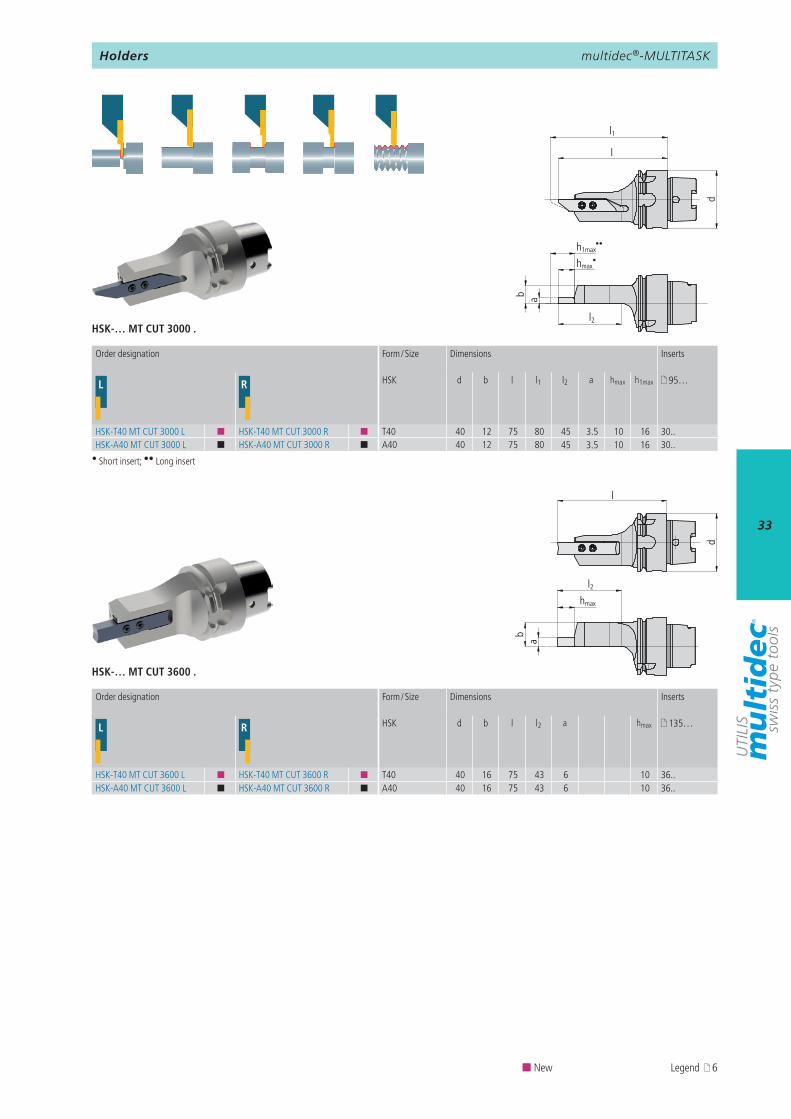
L R HSK d b l l2 a hmax 135…
HSK-T40 MT CUT 3600 L ¢ HSK-T40 MT CUT 3600 R ¢ T40 40 16 75 43 6 10 36..HSK-A40 MT CUT 3600 L ¢ HSK-A40 MT CUT 3600 R ¢ A40 40 16 75 43 6 10 36..
L R HSK d b l l1 l2 a hmax h1max 95…
HSK-T40 MT CUT 3000 L ¢ HSK-T40 MT CUT 3000 R ¢ T40 40 12 75 80 45 3.5 10 16 30..HSK-A40 MT CUT 3000 L ¢ HSK-A40 MT CUT 3000 R ¢ A40 40 12 75 80 45 3.5 10 16 30..
HSK-… MT CUT 3600 .
HSK-… MT CUT 3000 .
l
d
l1
l2
hmax
b
h1max
a
••
•
d
l
l2
ab
hmax
Order designation Form / Size Dimensions Inserts
Order designation Form / Size Dimensions Inserts
¢ New Legend 6
• Short insert; •• Long insert
Holders
multidec®-MULTITASK
34
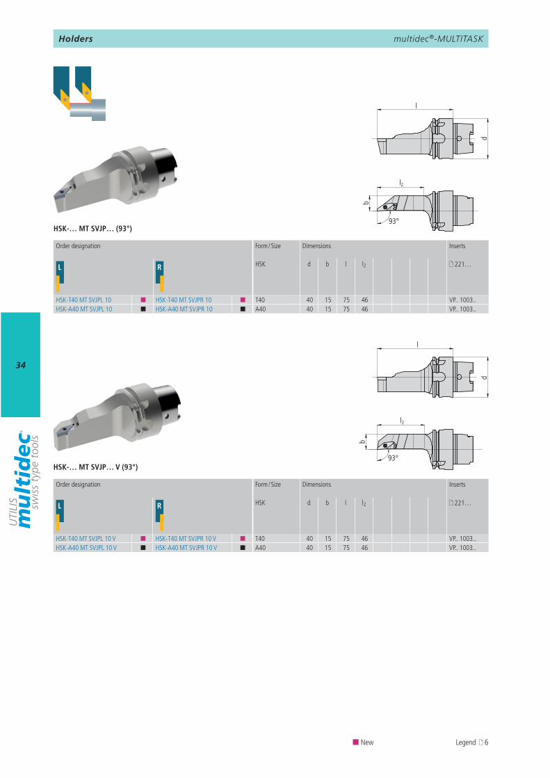
L R HSK d b l l2 221…
HSK-T40 MT SVJPL 10 ¢ HSK-T40 MT SVJPR 10 ¢ T40 40 15 75 46 VP.. 1003..HSK-A40 MT SVJPL 10 ¢ HSK-A40 MT SVJPR 10 ¢ A40 40 15 75 46 VP.. 1003..
L R HSK d b l l2 221…
HSK-T40 MT SVJPL 10 V ¢ HSK-T40 MT SVJPR 10 V ¢ T40 40 15 75 46 VP.. 1003..HSK-A40 MT SVJPL 10 V ¢ HSK-A40 MT SVJPR 10 V ¢ A40 40 15 75 46 VP.. 1003..
HSK-… MT SVJP… (93°)
HSK-… MT SVJP… V (93°)
d
l
b
l2
93°
d
l
l2
b
93°
¢ New Legend 6
Order designation Form / Size Dimensions Inserts
Order designation Form / Size Dimensions Inserts
Holders
multidec®-MULTITASK
35
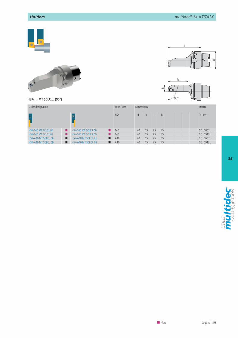
L R HSK d b l l2 149…
HSK-T40 MT SCLCL 06 ¢ HSK-T40 MT SCLCR 06 ¢ T40 40 15 75 45 CC.. 0602..HSK-T40 MT SCLCL 09 ¢ HSK-T40 MT SCLCR 09 ¢ T40 40 15 75 45 CC.. 09T3..HSK-A40 MT SCLCL 06 ¢ HSK-A40 MT SCLCR 06 ¢ A40 40 15 75 45 CC.. 0602..HSK-A40 MT SCLCL 09 ¢ HSK-A40 MT SCLCR 09 ¢ A40 40 15 75 45 CC.. 09T3..
HSK-… MT SCLC… (95°)
l
d
b
l2
95°
Order designation Form / Size Dimensions Inserts
¢ New Legend 6
Holders
multidec®-MULTITASK
36
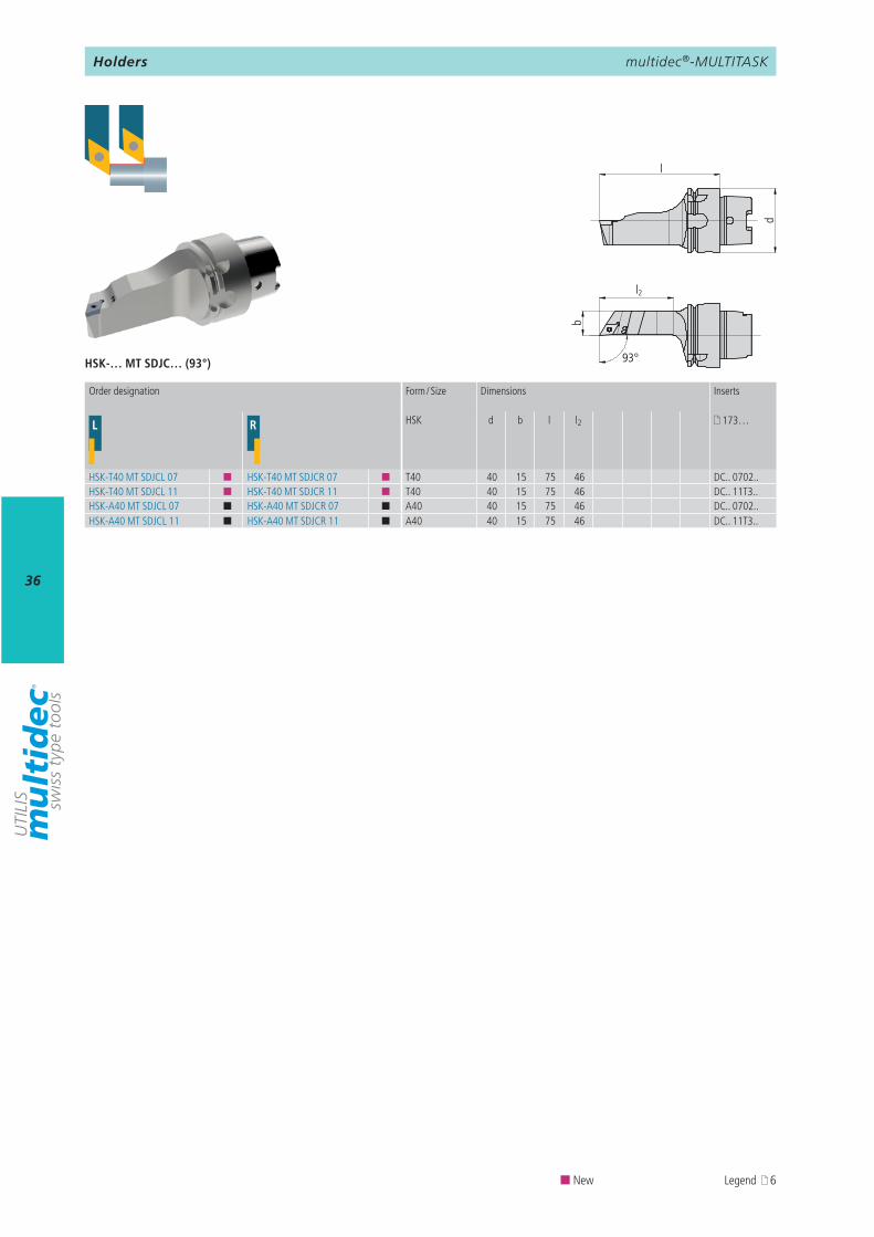
L R HSK d b l l2 173…
HSK-T40 MT SDJCL 07 ¢ HSK-T40 MT SDJCR 07 ¢ T40 40 15 75 46 DC.. 0702..HSK-T40 MT SDJCL 11 ¢ HSK-T40 MT SDJCR 11 ¢ T40 40 15 75 46 DC.. 11T3..HSK-A40 MT SDJCL 07 ¢ HSK-A40 MT SDJCR 07 ¢ A40 40 15 75 46 DC.. 0702..HSK-A40 MT SDJCL 11 ¢ HSK-A40 MT SDJCR 11 ¢ A40 40 15 75 46 DC.. 11T3..
HSK-… MT SDJC… (93°)
d
l
b
l2
93°
¢ New Legend 6
Order designation Form / Size Dimensions Inserts
Holders
multidec®-MULTITASK
37
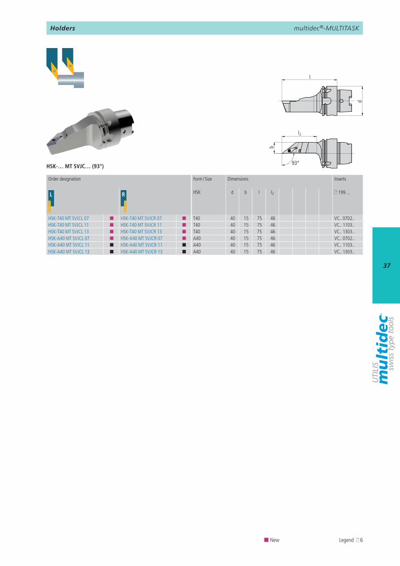
L R HSK d b l l2 199…
HSK-T40 MT SVJCL 07 ¢ HSK-T40 MT SVJCR 07 ¢ T40 40 15 75 46 VC.. 0702..HSK-T40 MT SVJCL 11 ¢ HSK-T40 MT SVJCR 11 ¢ T40 40 15 75 46 VC.. 1103..HSK-T40 MT SVJCL 13 ¢ HSK-T40 MT SVJCR 13 ¢ T40 40 15 75 46 VC.. 1303..HSK-A40 MT SVJCL 07 ¢ HSK-A40 MT SVJCR 07 ¢ A40 40 15 75 46 VC.. 0702..HSK-A40 MT SVJCL 11 ¢ HSK-A40 MT SVJCR 11 ¢ A40 40 15 75 46 VC.. 1103..HSK-A40 MT SVJCL 13 ¢ HSK-A40 MT SVJCR 13 ¢ A40 40 15 75 46 VC.. 1303..
HSK-… MT SVJC… (93°)
d
l
l2
b
93°
¢ New Legend 6
Order designation Form / Size Dimensions Inserts
Holders
multidec®-MULTITASK
38
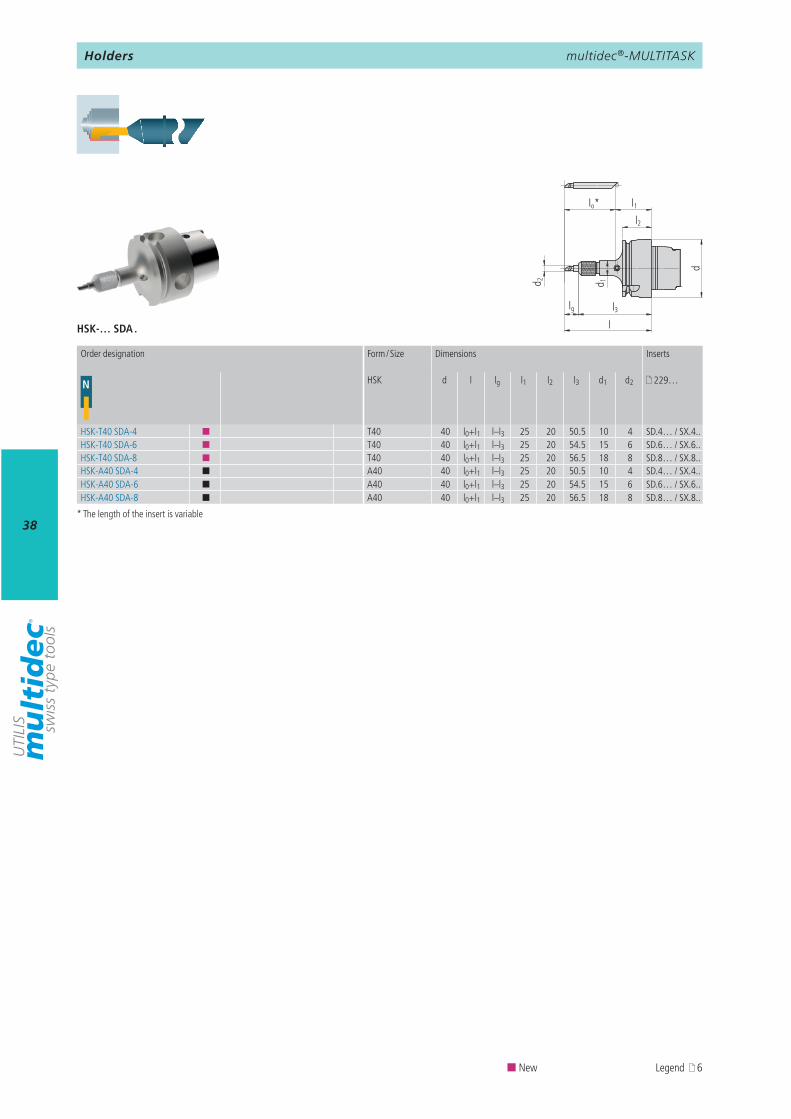
N HSK d l lg l1 l2 l3 d1 d2 229…
HSK-T40 SDA-4 ¢ T40 40 l0+l1 l–l3 25 20 50.5 10 4 SD.4… / SX.4..HSK-T40 SDA-6 ¢ T40 40 l0+l1 l–l3 25 20 54.5 15 6 SD.6… / SX.6..HSK-T40 SDA-8 ¢ T40 40 l0+l1 l–l3 25 20 56.5 18 8 SD.8… / SX.8..HSK-A40 SDA-4 ¢ A40 40 l0+l1 l–l3 25 20 50.5 10 4 SD.4… / SX.4..HSK-A40 SDA-6 ¢ A40 40 l0+l1 l–l3 25 20 54.5 15 6 SD.6… / SX.6..HSK-A40 SDA-8 ¢ A40 40 l0+l1 l–l3 25 20 56.5 18 8 SD.8… / SX.8..
HSK-… SDA .
d 1
lo* l1
l3l
d
l2
d 2
lg
Order designation Form / Size Dimensions Inserts
¢ New Legend 6
* The length of the insert is variable
Holders
multidec®-MULTITASK
39
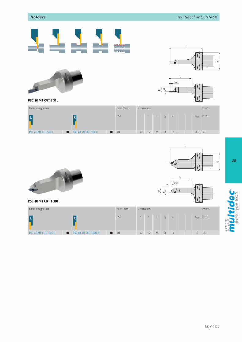
L R PSC d b l l2 a hmax 59…
PSC 40 MT CUT 500 L ¢ PSC 40 MT CUT 500 R ¢ 40 40 12 75 50 2 8.5 50.
L R PSC d b l l2 a hmax 63…
PSC 40 MT CUT 1600 L ¢ PSC 40 MT CUT 1600 R ¢ 40 40 12 75 50 3 5 16..
PSC 40 MT CUT 500 .
PSC 40 MT CUT 1600 .
d
l
l2
ab
hmax
d
l
hmax
l2
ab
Order designation Form / Size Dimensions Inserts
Order designation Form / Size Dimensions Inserts
Holders
Legend 6
multidec®-MULTITASK
40
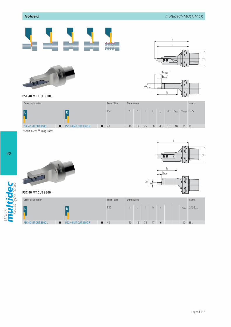
L R PSC d b l l2 a hmax 135…
PSC 40 MT CUT 3600 L ¢ PSC 40 MT CUT 3600 R ¢ 40 40 16 75 47 6 10 36..
L R PSC d b l l1 l2 a hmax h1max 95…
PSC 40 MT CUT 3000 L ¢ PSC 40 MT CUT 3000 R ¢ 40 40 12 75 80 48 3.5 10 16 30..
PSC 40 MT CUT 3600 .
PSC 40 MT CUT 3000 .
ab
hmax
l2
h1max
d
l
l1
••
•
d
l
ab
hmax
l2
Order designation Form / Size Dimensions Inserts
Order designation Form / Size Dimensions Inserts
• Short insert; •• Long insert
Holders
Legend 6
multidec®-MULTITASK
41
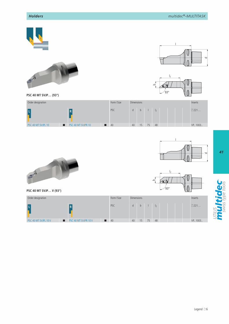
L R PSC d b l l2 221…
PSC 40 MT SVJPL 10 ¢ PSC 40 MT SVJPR 10 ¢ 40 40 15 75 48 VP.. 1003..
L R PSC d b l l2 221…
PSC 40 MT SVJPL 10 V ¢ PSC 40 MT SVJPR 10 V ¢ 40 40 15 75 48 VP.. 1003..
PSC 40 MT SVJP… (93°)
PSC 40 MT SVJP… V (93°)
d
l
l2
b
93°
l
d
l2
b
93°
Order designation Form / Size Dimensions Inserts
Order designation Form / Size Dimensions Inserts
Holders
Legend 6
multidec®-MULTITASK
42
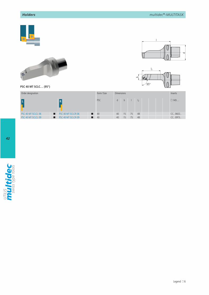
L R PSC d b l l2 149…
PSC 40 MT SCLCL 06 ¢ PSC 40 MT SCLCR 06 ¢ 40 40 15 75 48 CC.. 0602..PSC 40 MT SCLCL 09 ¢ PSC 40 MT SCLCR 09 ¢ 40 40 15 75 48 CC.. 09T3..
PSC 40 MT SCLC… (95°)
d
l
l2
b
95°
Order designation Form / Size Dimensions Inserts
Holders
Legend 6
multidec®-MULTITASK
43
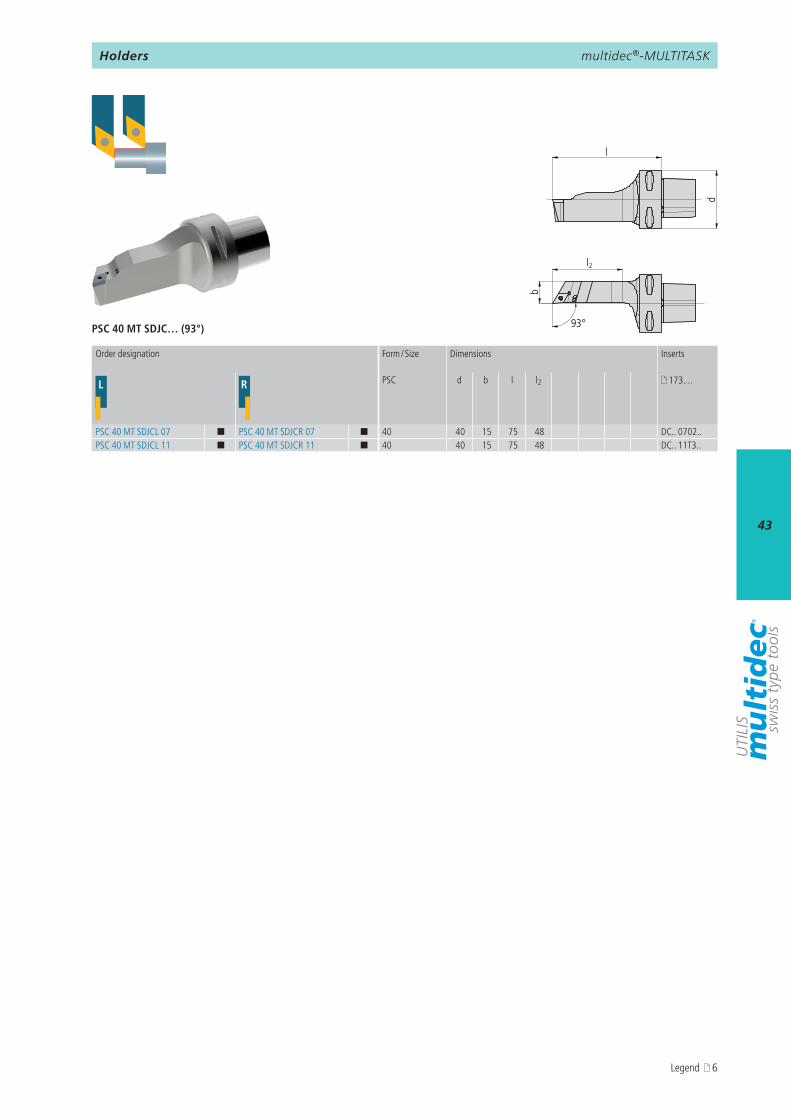
L R PSC d b l l2 173…
PSC 40 MT SDJCL 07 ¢ PSC 40 MT SDJCR 07 ¢ 40 40 15 75 48 DC.. 0702..PSC 40 MT SDJCL 11 ¢ PSC 40 MT SDJCR 11 ¢ 40 40 15 75 48 DC.. 11T3..
PSC 40 MT SDJC… (93°)
l
d
l2
b
93°
Order designation Form / Size Dimensions Inserts
Holders
Legend 6
multidec®-MULTITASK
44
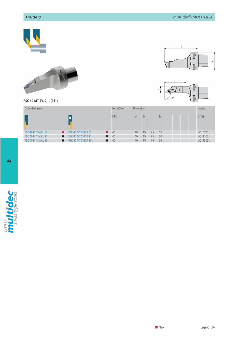
L R PSC d b l l2 199…
PSC 40 MT SVJCL 07 ¢ PSC 40 MT SVJCR 07 ¢ 40 40 15 75 50 VC.. 0702..PSC 40 MT SVJCL 11 ¢ PSC 40 MT SVJCR 11 ¢ 40 40 15 75 50 VC.. 1103..PSC 40 MT SVJCL 13 ¢ PSC 40 MT SVJCR 13 ¢ 40 40 15 75 50 VC.. 1303..
PSC 40 MT SVJC… (93°)
d
l
l2
b
93°
Order designation Form / Size Dimensions Inserts
¢ New Legend 6
Holders
multidec®-MULTITASK
45
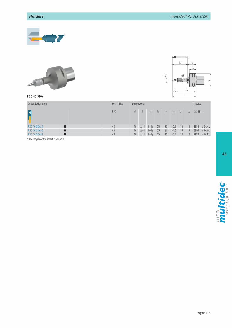
N PSC d l l9 l1 l2 l3 d1 d2 229…
PSC 40 SDA-4 ¢ 40 40 l0 + l1 l – l3 25 20 50.5 10 4 SD.4… / SX.4..PSC 40 SDA-6 ¢ 40 40 l0 + l1 l – l3 25 20 54.5 15 6 SD.6… / SX.6..PSC 40 SDA-8 ¢ 40 40 l0 + l1 l – l3 25 20 56.5 18 8 SD.8… / SX.8..
PSC 40 SDA .
l0*
lg
l
d
l1l2
d 2 d 1
l3
Order designation Form / Size Dimensions Inserts
* The length of the insert is variable
Holders
Legend 6
multidec®-MULTITASK
46
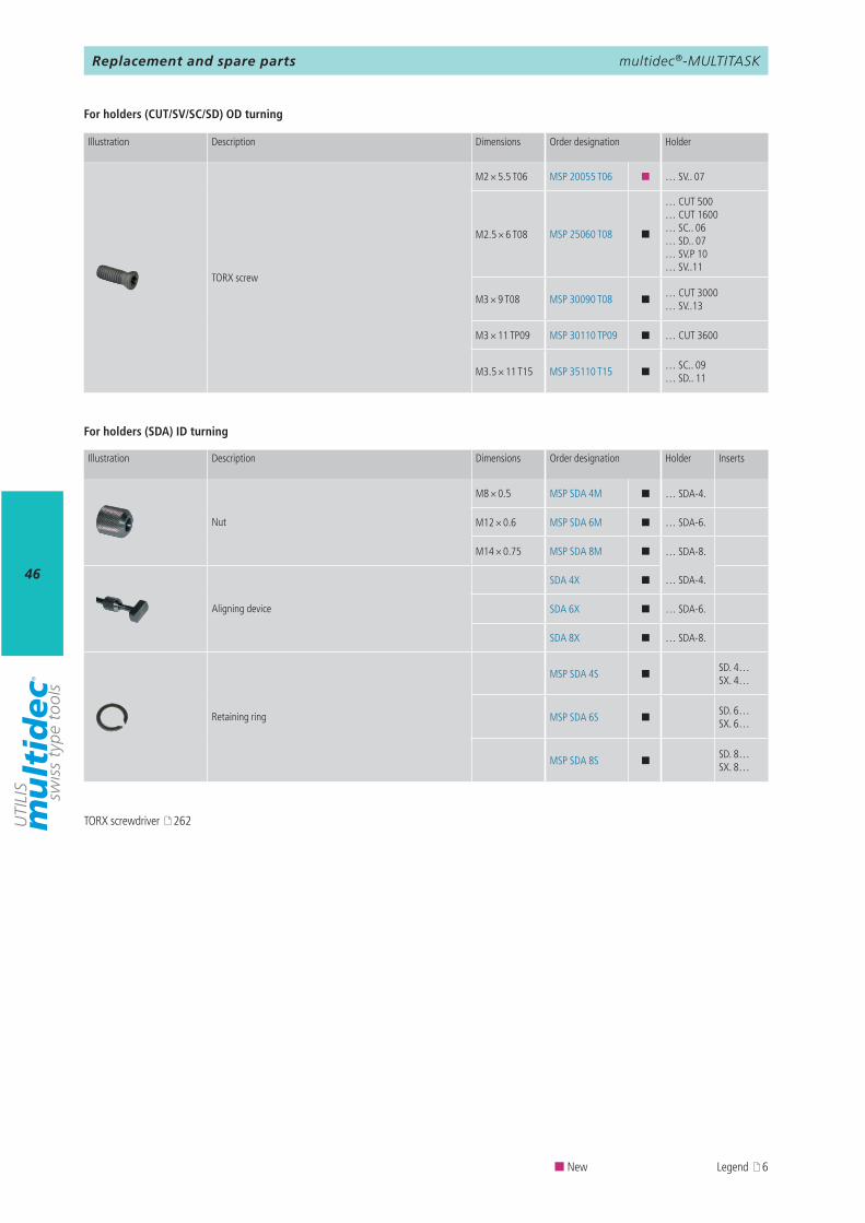
M2 × 5.5 T06 MSP 20055 T06 ¢ … SV.. 07
M2.5 × 6 T08 MSP 25060 T08 ¢
… CUT 500 … CUT 1600 … SC.. 06 … SD.. 07 … SV.P 10 … SV..11
M3 × 9 T08 MSP 30090 T08 ¢… CUT 3000 … SV..13
M3 × 11 TP09 MSP 30110 TP09 ¢ … CUT 3600
M3.5 × 11 T15 MSP 35110 T15 ¢… SC.. 09 … SD.. 11
M8 × 0.5 MSP SDA 4M ¢ … SDA-4.
M12 × 0.6 MSP SDA 6M ¢ … SDA-6.
M14 × 0.75 MSP SDA 8M ¢ … SDA-8.
SDA 4X ¢ … SDA-4.
SDA 6X ¢ … SDA-6.
SDA 8X ¢ … SDA-8.
MSP SDA 4S ¢SD. 4… SX. 4…
MSP SDA 6S ¢SD. 6… SX. 6…
MSP SDA 8S ¢SD. 8… SX. 8…
Illustration Description Dimensions Order designation Holder
TORX screw
For holders (CUT/SV/SC/SD) OD turning
For holders (SDA) ID turning
Illustration Description Dimensions Order designation Holder Inserts
Nut
Aligning device
Retaining ring
Replacement and spare parts
TORX screwdriver 262
¢ New Legend 6
multidec®-MULTITASK
47
AttentionPlease note the legend 6…
Notes
multidec®-CUT
48
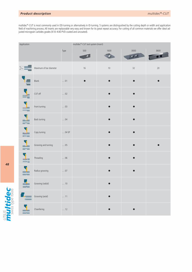
500 1600 3000 3600
Dmax 16 10 32 20
… 01
… 02
… 03
… 04
… 04 SP
… 05
… 06
… 07
… 10
… 11
… 12
Product description
Application multidec®-CUT tool system (insert)
Type
Maximum of bar diameter
Blank
CUT off
Front turning
Back turning
Copy turning
Grooving and turning
Threading
Radius-grooving
Grooving (radial)
Grooving (axial)
Chamfering
multidec®-CUT is most commonly used in OD-turning or alternatively in ID-turning. 5 systems are distinguished by the cutting depth or width and application field of machining process. All inserts are replaceable very easy and known for its great repeat accuracy. For cutting of all common materials we offer ideal ad-justed micrograin carbides grades (K10–K40 PVD coated and uncoated).
multidec®-CUT
49
9 50 52 54 STANDARD-LINE
Article no. 126600 P4563213000 - 08 - 100 L A
57
59 63 95 135
Stahl unlegiertAcier non alliéSteel unalloyed
Stahl niedriglegiertAcier faibl. alliéSteel low alloyed
Stahl hochlegiertAcier fortem. alliéSteel high alloyed
TitanTitaneTitanium
Härte (HB)Dureté (HB)Hardness value (HB)
125–300 180–250 200–350 –
KategorieCatégrieCategory
I II III IV
BearbeitungUsinageMachining method
140 142 143 625
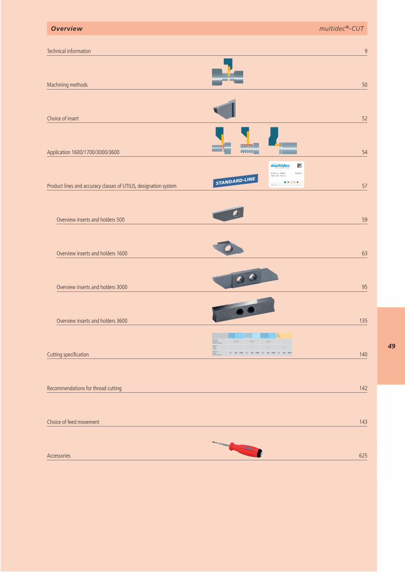
multidec®-CUTOverview
Technical information Machining methods Choice of insert Application 1600/1700/3000/3600 Product lines and accuracy classes of UTILIS, designation system
Overview inserts and holders 500 Overview inserts and holders 1600 Overview inserts and holders 3000 Overview inserts and holders 3600
Cutting specification Recommendations for thread cutting Choice of feed movement Accessories
multidec®-CUT
50
1
2
3
4
5
6
7
A B
R
L
L
L
L
L
L
L
L
R
R
R
R
R
R
R
R
R
L
L
LV
LV
LV
LN
LN
LN
LNLV
LA
LA
LAV
LAV
RAV
RAV
RV
RV
RV
RV
RV
RV
RA
RA
RN
RN
RN
RN
RN
RN
RV
LV
LVLN
LN LV
Machining methods
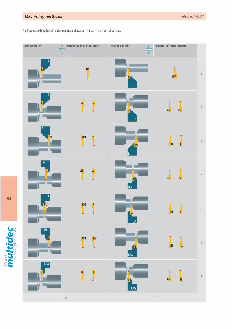
A different combination of holder and insert allows cutting even in difficult situations.
Main-spindle left Possibilities of insert execution Main-spindle left Possibilities of insert execution
multidec®-CUT
51
1
2
3
4
5
6
7
C D
L
L
L
L
L
L
L
L
L
L
R
R
R
R
R
R
R
R
R
RAV
RAV
LAV
LAV
LV
LV
LV
LV
LA
LA
LN
LN
LN
LN
RV
RV
RV
RV
RN
RN
RN
RN
RA
RA
RV
RV
RV
LV
LV
LV
LN
LN
RRN
RN
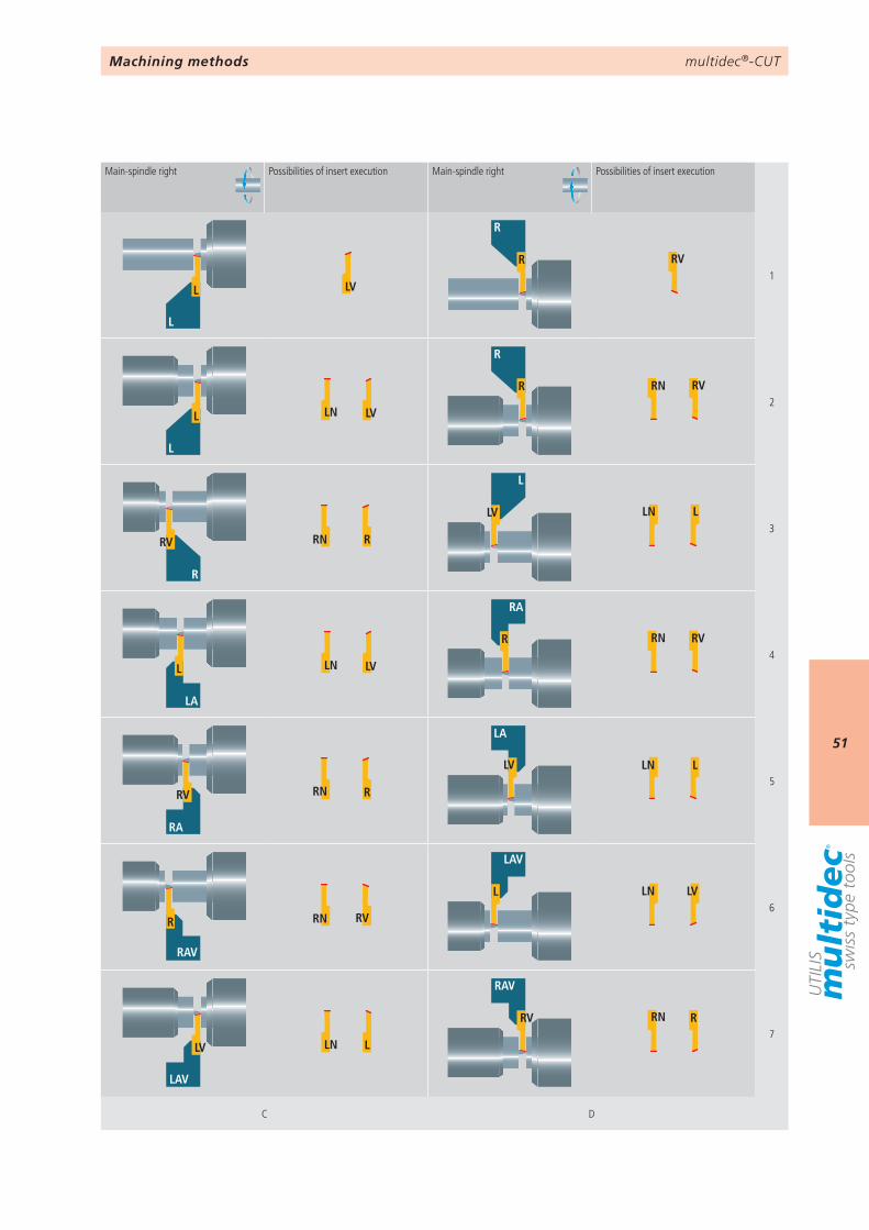
Machining methods
Main-spindle right Possibilities of insert execution Main-spindle right Possibilities of insert execution
multidec®-CUT
52
… 02
– –
… 02 GS
––––
… 02 SC
–
… 02 SPT
– – –
… 03
– –
… 03 SP
… 03 CP TOP
… 04
– –
… 04 CP
… 04 SP
… 04 TOP
… 05
–
… 05 CP
… 06
– –– –– ––
… 06 VP
– –– –– ––
… 07
––––
… 10
––––
… 11
––––
… 12
––––
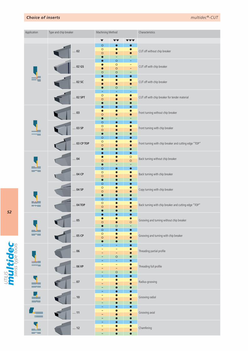
Choice of inserts
Application Type and chip breaker Machining Method Characteristics
CUT off without chip breaker
CUT off with chip breaker
CUT off with chip breaker
CUT off with chip breaker for tender material
Front turning without chip breaker
Front turning with chip breaker
Front turning with chip breaker and cutting edge “TOP”
Back turning without chip breaker
Back turning with chip breaker
Copy turning with chip breaker
Back turning with chip breaker and cutting edge “TOP”
Grooving and turning without chip breaker
Grooving and turning with chip breaker
Threading partial profile
Threading full profile
Radius-grooving
Grooving radial
Grooving axial
Chamfering

multidec®-CUT
53
AttentionPlease note the legend 6…
Notes
multidec®-CUT 1600
54
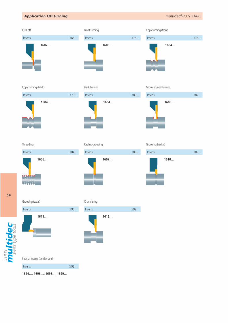
1694…, 1696…, 1698…, 1699…
93…
66… 75…
79… 82…
88… 84… 89…
90…
1602… 1603…
1604… 1605…
1606… 1607… 1610…
1611…
78…
1604…
80…
1604…
1612…
92…
Special inserts (on demand)
Inserts
Application OD turning
Grooving (axial)
CUT off Front turning
Grooving and Turning
Threading Grooving (radial)
Copy turning (back)
Inserts
Radius-grooving
Inserts
Inserts Inserts
InsertsInserts Inserts
Inserts
Copy turning (front)
Inserts
Back turning
Inserts
Chamfering
Inserts
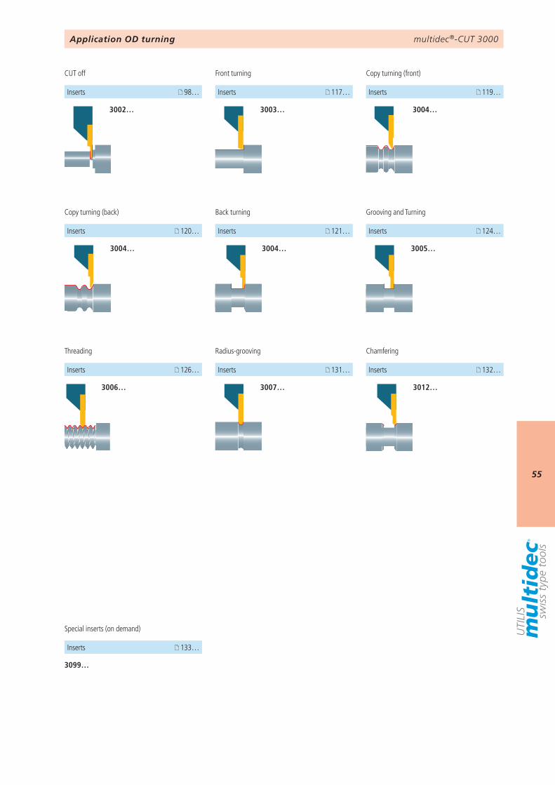
multidec®-CUT 3000
55
98…
120… 124…
131… 126…
3002…
3004… 3005…
3006… 3007…
119…
3004…
121…
3004…
117…
3003…
3012…
132…
3099…
133…
Application OD turning
CUT off
Grooving and Turning
Threading
Copy turning (back)
Inserts
Radius-grooving
Inserts Inserts
InsertsInserts
Copy turning (front)
Inserts
Back turning
Inserts
Front turning
Inserts
Chamfering
Inserts
Special inserts (on demand)
Inserts
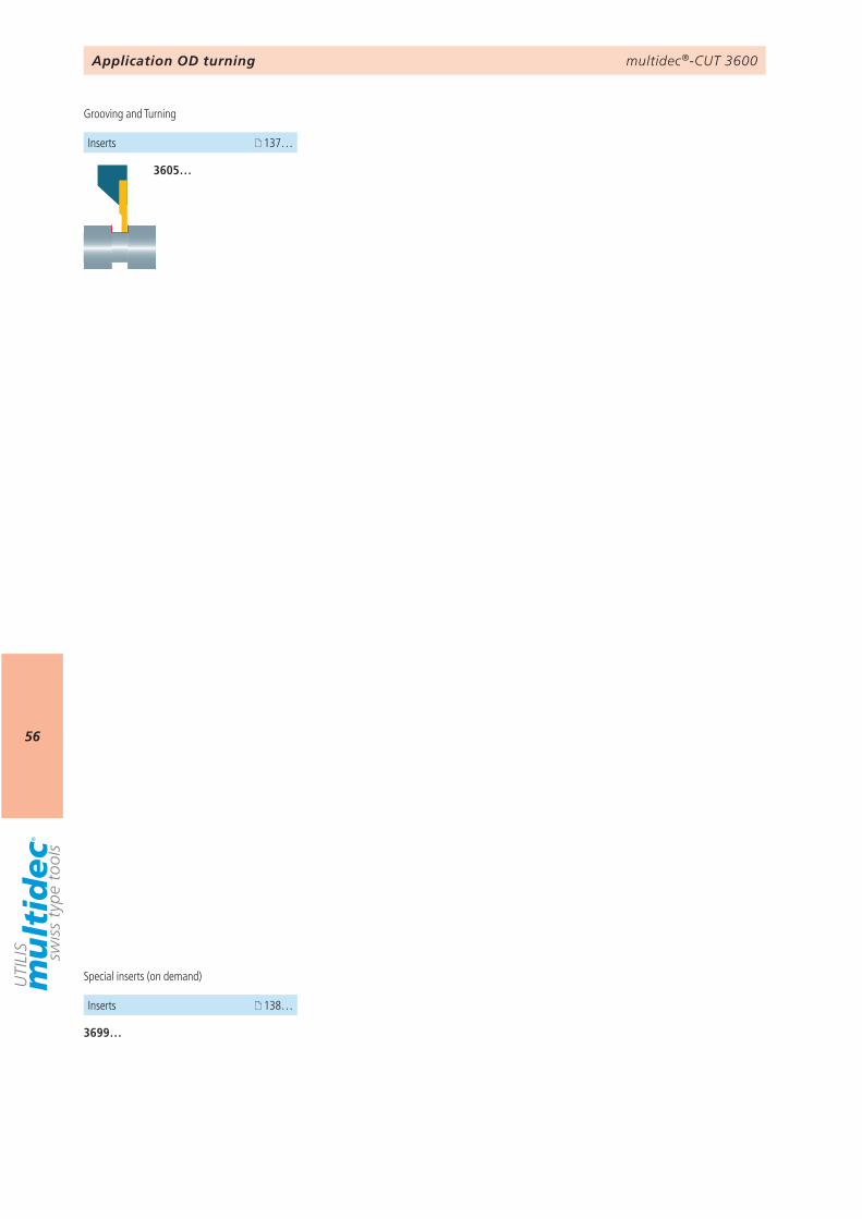
multidec®-CUT 3600
56
137…
3605…
3699…
138…
Application OD turning
Grooving and Turning
Inserts
Special inserts (on demand)
Inserts
multidec®-CUT
57
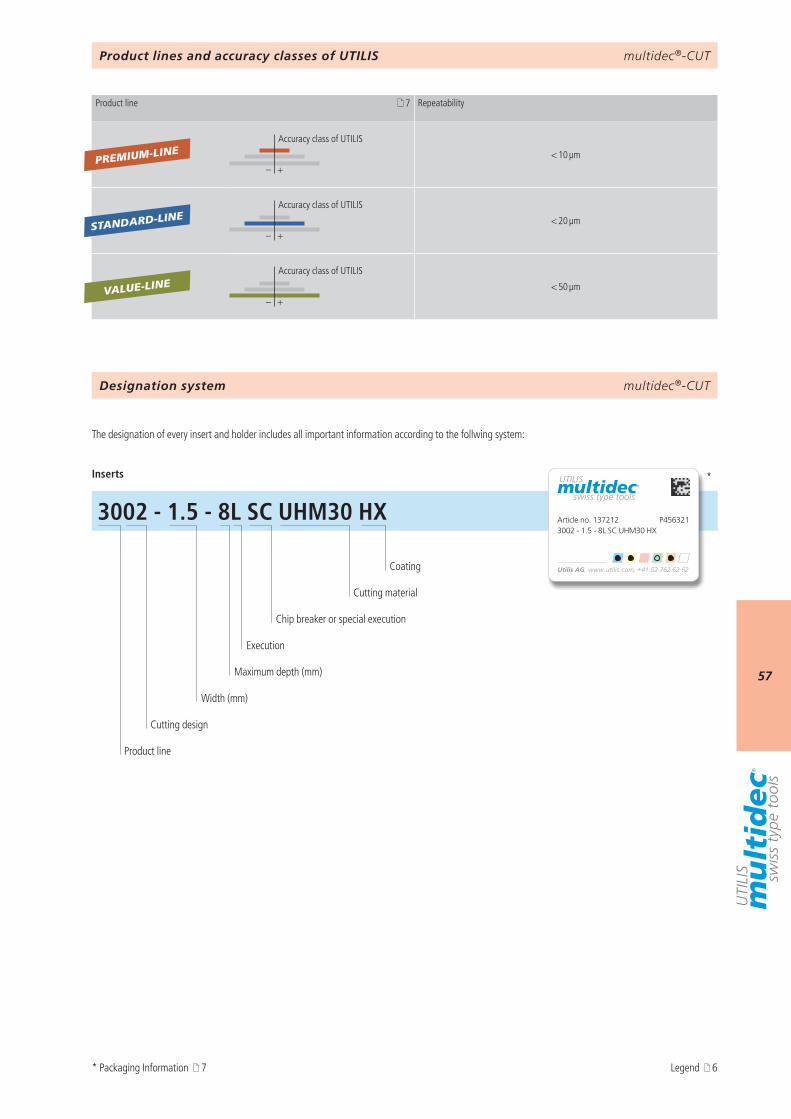
3002 - 1.5 - 8L SC UHM30 HX Article no. 137212 P4563213002 - 1.5 - 8L SC UHM30 HX
*
7
– +
– +
– +
PREMIUM-LINE
VALUE-LINE
STANDARD-LINE
multidec®-CUTDesignation system
Product lines and accuracy classes of UTILIS
The designation of every insert and holder includes all important information according to the follwing system:
Inserts
Coating
Cutting material
Chip breaker or special execution
Execution
Maximum depth (mm)
Width (mm)
Cutting design
Product line
* Packaging Information 7 Legend 6
Product line Repeatability
Accuracy class of UTILIS
< 10 µm
Accuracy class of UTILIS
< 20 µm
Accuracy class of UTILIS
< 50 µm
multidec®-CUT 500
58
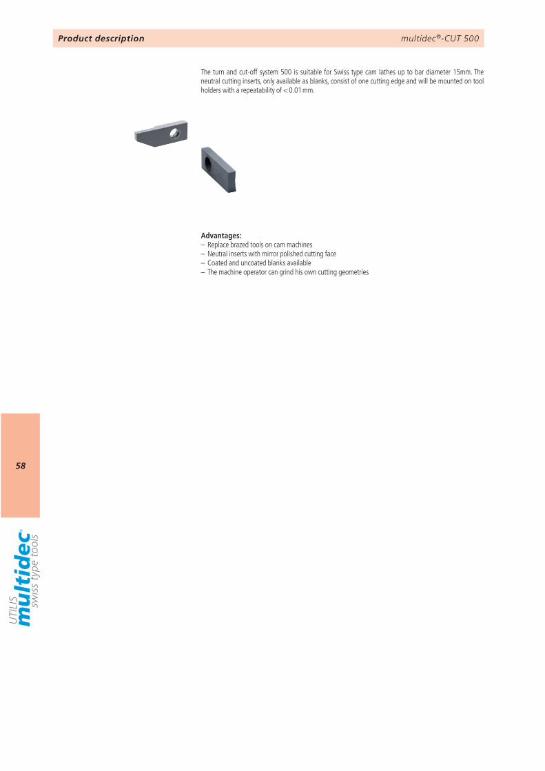
Product description
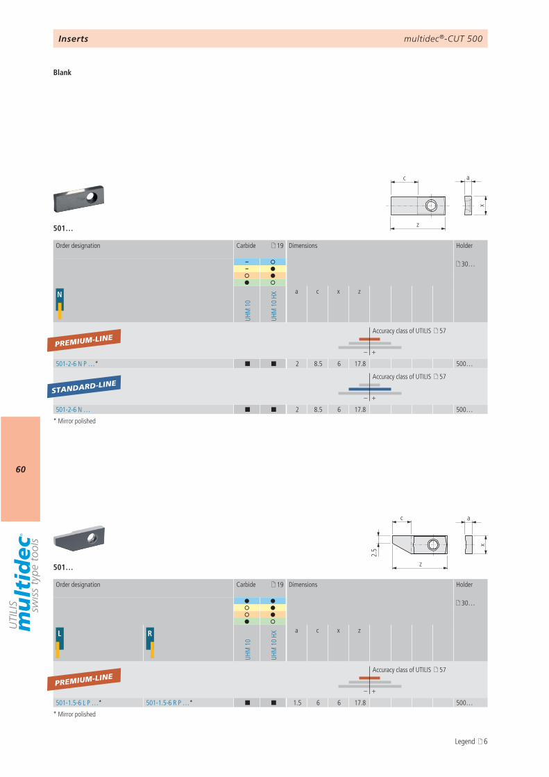
The turn and cut-off system 500 is suitable for Swiss type cam lathes up to bar diameter 15mm. The neutral cutting inserts, only available as blanks, consist of one cutting edge and will be mounted on tool holders with a repeatability of < 0.01 mm.
Advantages:– Replace brazed tools on cam machines– Neutral inserts with mirror polished cutting face– Coated and uncoated blanks available– The machine operator can grind his own cutting geometries

multidec®-CUT 500
59
9 501… 60
multidec®-CUT 500
Technical information Inserts
Overview
multidec®-CUT 500
60
z
c a
x
c a
x
2.5
z
501…
501…
19
– 30…–
N
UHM
10
UHM
10
HX
a c x z
– +
501-2-6 N P …* ¢ ¢ 2 8.5 6 17.8 500…
– +
501-2-6 N … ¢ ¢ 2 8.5 6 17.8 500…
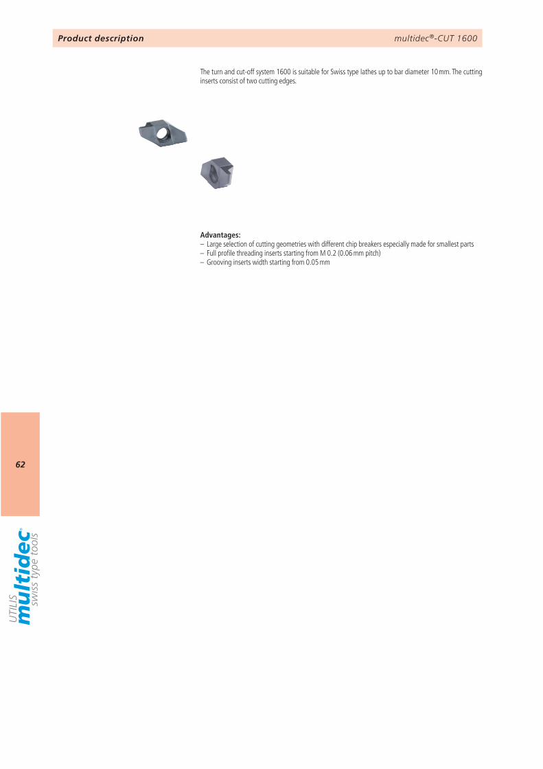
19
30…
L R
UHM
10
UHM
10
HX
a c x z
– +
501-1.5-6 L P …* 501-1.5-6 R P …* ¢ ¢ 1.5 6 6 17.8 500…
PREMIUM-LINE
PREMIUM-LINE
STANDARD-LINE
Inserts
Blank
* Mirror polished
* Mirror polished
Order designation Carbide Dimensions Holder
Accuracy class of UTILIS 57
Accuracy class of UTILIS 57
Order designation Carbide Dimensions Holder
Accuracy class of UTILIS 57
Legend 6

multidec®-CUT 500
61
AttentionPlease note the legend 6…
Notes
multidec®-CUT 1600
62
Product description
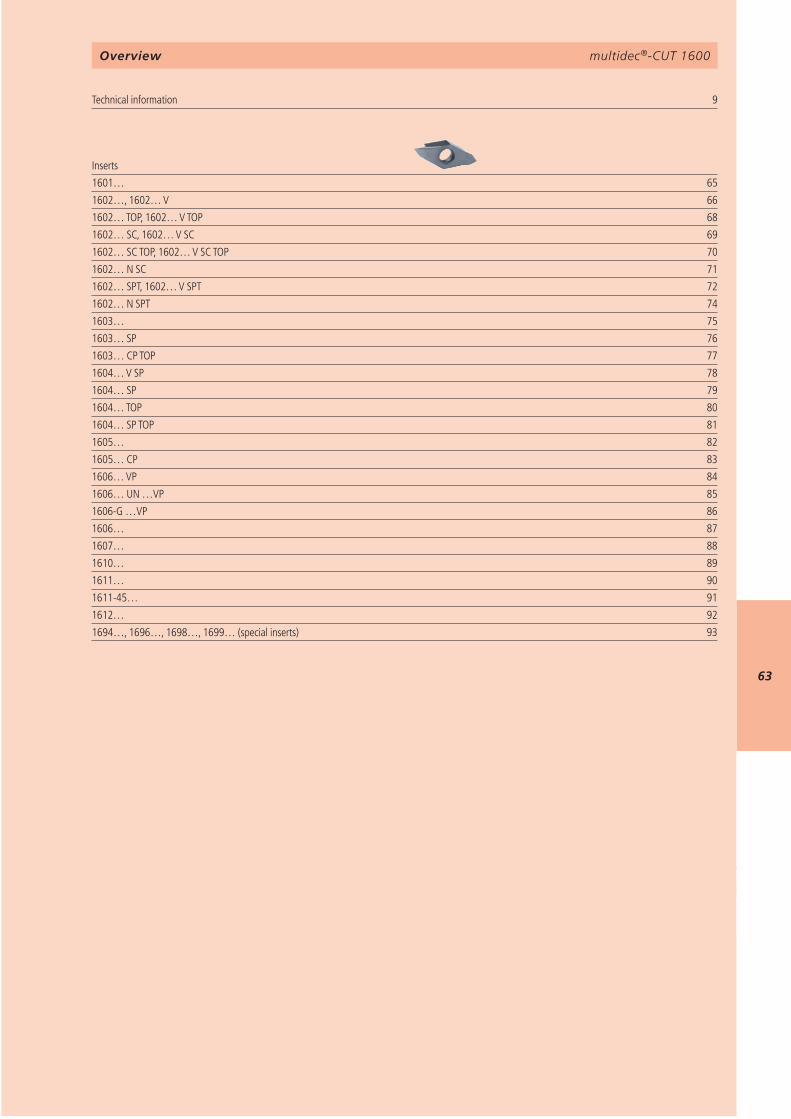
The turn and cut-off system 1600 is suitable for Swiss type lathes up to bar diameter 10 mm. The cutting inserts consist of two cutting edges.
Advantages:– Large selection of cutting geometries with different chip breakers especially made for smallest parts– Full profile threading inserts starting from M 0.2 (0.06 mm pitch)– Grooving inserts width starting from 0.05 mm
multidec®-CUT 1600
63
9 1601… 651602…, 1602… V 661602… TOP, 1602… V TOP 681602… SC, 1602… V SC 691602… SC TOP, 1602… V SC TOP 701602… N SC 711602… SPT, 1602… V SPT 721602… N SPT 741603… 751603… SP 761603… CP TOP 771604… V SP 781604… SP 791604… TOP 801604… SP TOP 811605… 821605… CP 831606… VP 841606… UN …VP 851606-G …VP 861606… 871607… 881610… 891611… 901611-45… 911612… 92 93
multidec®-CUT 1600
Technical information Inserts
1694…, 1696…, 1698…, 1699… (special inserts)
Overview
multidec®-CUT 1600
64
AttentionPlease note the legend 6…
Notes
multidec®-CUT 1600
65
c
z
x
a
z
x
ac
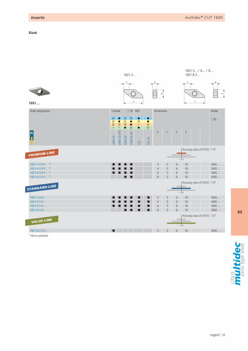
1601-4… / -6… / -8… 1601 B-3…1601-3…
1601…
19
30…
–– –
N
UHM
20
UHM
20
HPX
UHM
30
UHM
30
HX
HSS
HSS
HX
a c x z
– +
1601-3-5 N P …* ¢ ¢ ¢ ¢ 3 5 6 16 1600…1601-4-5 N P …* ¢ ¢ ¢ ¢ 4 5 6 16 1600…1601-6-5 N P …* ¢ ¢ ¢ ¢ 6 5 6 16 1600…1601-8-5 N P …* ¢ ¢ 8 5 6 16 1600…
– +
1601-3-5 N … ¢ ¢ ¢ ¢ ¢ ¢ 3 5 6 16 1600…1601-4-5 N … ¢ ¢ ¢ ¢ ¢ ¢ 4 5 6 16 1600…1601-6-5 N … ¢ ¢ ¢ ¢ ¢ ¢ 6 5 6 16 1600…1601-8-5 N … ¢ ¢ ¢ ¢ 8 5 6 16 1600…
– +
1601 B-3-5 N … ¢ 3 5 6 16 1600…
PREMIUM-LINE
STANDARD-LINE
VALUE-LINE
Inserts
Blank
* Mirror polished
Order designation Carbide HSS Dimensions Holder
Accuracy class of UTILIS 57
Accuracy class of UTILIS 57
Accuracy class of UTILIS 57
Legend 6
multidec®-CUT 1600
66
αc
ar
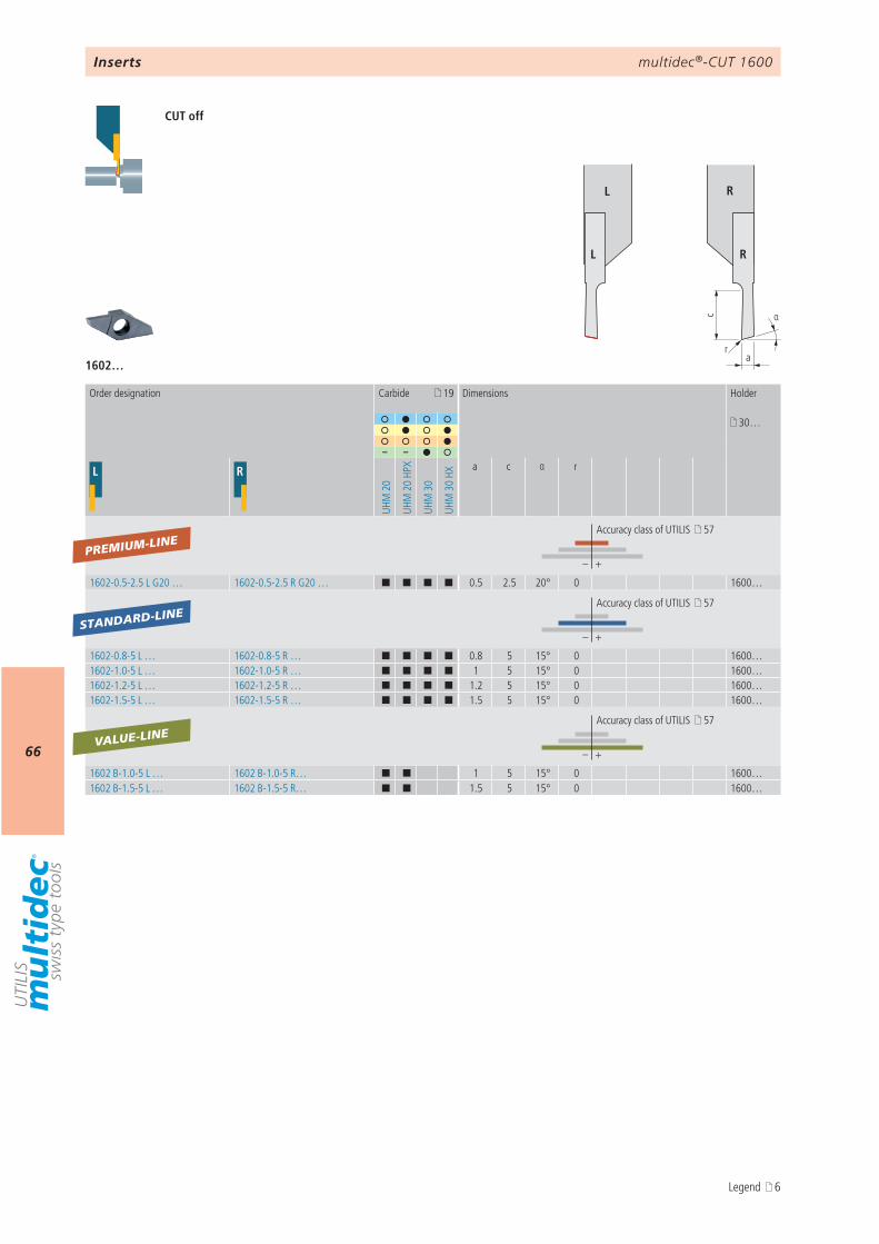
L R
L R
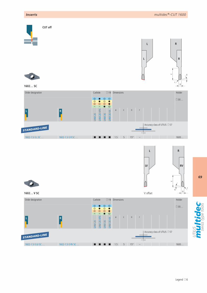
1602…
19
30…
– –
L R
UHM
20
UHM
20
HPX
UHM
30
UHM
30
HX
a c α r
– +
1602-0.5-2.5 L G20 … 1602-0.5-2.5 R G20 … ¢ ¢ ¢ ¢ 0.5 2.5 20° 0 1600…
– +
1602-0.8-5 L … 1602-0.8-5 R … ¢ ¢ ¢ ¢ 0.8 5 15° 0 1600…1602-1.0-5 L … 1602-1.0-5 R … ¢ ¢ ¢ ¢ 1 5 15° 0 1600…1602-1.2-5 L … 1602-1.2-5 R … ¢ ¢ ¢ ¢ 1.2 5 15° 0 1600…1602-1.5-5 L … 1602-1.5-5 R … ¢ ¢ ¢ ¢ 1.5 5 15° 0 1600…
– +
1602 B-1.0-5 L … 1602 B-1.0-5 R… ¢ ¢ 1 5 15° 0 1600…1602 B-1.5-5 L … 1602 B-1.5-5 R… ¢ ¢ 1.5 5 15° 0 1600…
PREMIUM-LINE
STANDARD-LINE
VALUE-LINE
Inserts
CUT off
Order designation Carbide Dimensions Holder
Accuracy class of UTILIS 57
Accuracy class of UTILIS 57
Accuracy class of UTILIS 57
Legend 6
multidec®-CUT 1600
67
r
αc
a
L R
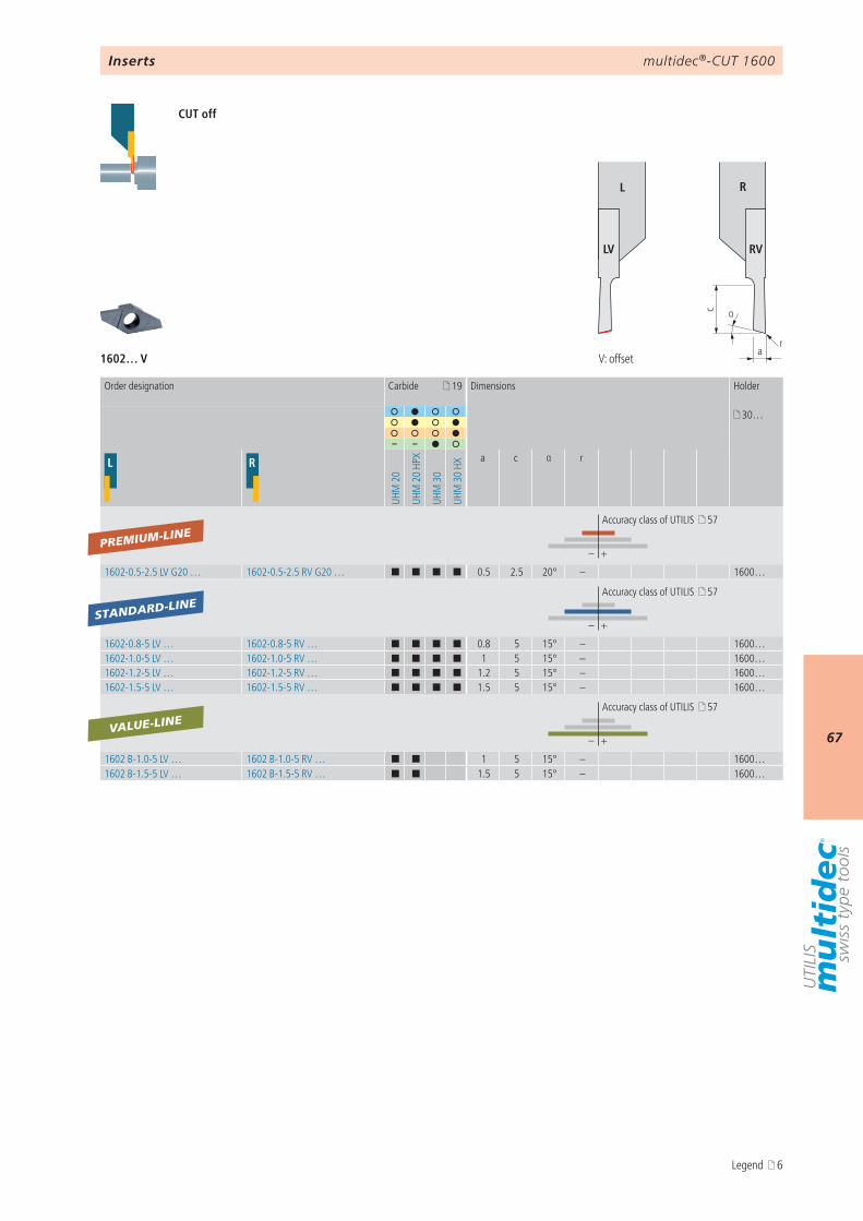
LV RV
1602… V
19
30…
– –
L R
UHM
20
UHM
20
HPX
UHM
30
UHM
30
HXa c α r
– +
1602-0.5-2.5 LV G20 … 1602-0.5-2.5 RV G20 … ¢ ¢ ¢ ¢ 0.5 2.5 20° – 1600…
– +
1602-0.8-5 LV … 1602-0.8-5 RV … ¢ ¢ ¢ ¢ 0.8 5 15° – 1600…1602-1.0-5 LV … 1602-1.0-5 RV … ¢ ¢ ¢ ¢ 1 5 15° – 1600…1602-1.2-5 LV … 1602-1.2-5 RV … ¢ ¢ ¢ ¢ 1.2 5 15° – 1600…1602-1.5-5 LV … 1602-1.5-5 RV … ¢ ¢ ¢ ¢ 1.5 5 15° – 1600…
– +
1602 B-1.0-5 LV … 1602 B-1.0-5 RV … ¢ ¢ 1 5 15° – 1600…1602 B-1.5-5 LV … 1602 B-1.5-5 RV … ¢ ¢ 1.5 5 15° – 1600…
PREMIUM-LINE
STANDARD-LINE
VALUE-LINE
Inserts
CUT off
V: offset
Order designation Carbide Dimensions Holder
Accuracy class of UTILIS 57
Accuracy class of UTILIS 57
Accuracy class of UTILIS 57
Legend 6
multidec®-CUT 1600
68
αc
ra
βb
a pm
ax
Detail TOP*
r
L R
L R
r
αc
arβ
b
a pm
ax
Detail TOP*
L R
LV RV
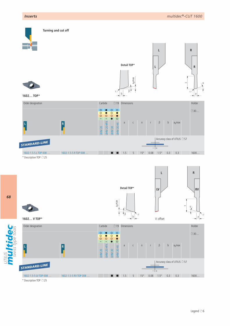
1602… TOP*
1602… V TOP*
19
30…
– –
L R
UHM
20
UHM
20
HPX
UHM
30
UHM
30
HX
a c α r β b apmax
– +
1602-1.5-5 L TOP 008 … 1602-1.5-5 R TOP 008 … ¢ ¢ 1.5 5 15° 0.08 1.5° 0.3 0.3 1600…
19
30…
– –
L R
UHM
20
UHM
20
HPX
UHM
30
UHM
30
HX
a c α r β b apmax
– +
1602-1.5-5 LV TOP 008 … 1602-1.5-5 RV TOP 008 … ¢ ¢ 1.5 5 15° 0.08 1.5° 0.3 0.3 1600…
STANDARD-LINE
STANDARD-LINE
Inserts
Turning and cut off
V: offset
Order designation Carbide Dimensions Holder
Accuracy class of UTILIS 57
Order designation Carbide Dimensions Holder
Accuracy class of UTILIS 57
* Description TOP 25
* Description TOP 25
Legend 6
multidec®-CUT 1600
69
αc
ar
L R
L R
1602… SC
αa
r
c
L R
LV RV
1602… V SC
19
30…
– –
L R
UHM
20
UHM
20
HPX
UHM
30
UHM
30
HXa c α r
– +
1602-1.5-5 L SC … 1602-1.5-5 R SC … ¢ ¢ ¢ ¢ 1.5 5 15° – 1600…
19
30…
– –
L R
UHM
20
UHM
20
HPX
UHM
30
UHM
30
HX
a c α r
– +
1602-1.5-5 LV SC … 1602-1.5-5 RV SC … ¢ ¢ ¢ ¢ 1.5 5 15° – 1600…
STANDARD-LINE
STANDARD-LINE
CUT off
Inserts
V: offset
Order designation Carbide Dimensions Holder
Accuracy class of UTILIS 57
Order designation Carbide Dimensions Holder
Accuracy class of UTILIS 57
Legend 6

multidec®-CUT 1600
70
αc
arr β
b
a pm
ax
Detail TOP*
L R
L R
αa
r
c
rβb
a pm
ax
Detail TOP*
L R
LV RV
1602… SC TOP*
1602… V SC TOP*
19
30…
– –
L R
UHM
20
UHM
20
HPX
UHM
30
UHM
30
HX
a c α r β b apmax
– +
1602-1.5-5 L SC TOP 008 … 1602-1.5-5 R SC TOP 008 … ¢ ¢ 1.5 5 15° 0.08 1.5° 0.3 0.3 1600…
19
30…
– –
L R
UHM
20
UHM
20
HPX
UHM
30
UHM
30
HX
a c α r β b apmax
– +
1602-1.5-5 LV SC TOP 008 … 1602-1.5-5 RV SC TOP 008 … ¢ ¢ 1.5 5 15° 0.08 1.5° 0.3 0.3 1600…
STANDARD-LINE
STANDARD-LINE
Inserts
Turning and cut off
V: offset
Order designation Carbide Dimensions Holder
Accuracy class of UTILIS 57
Order designation Carbide Dimensions Holder
Accuracy class of UTILIS 57
* Description TOP 25
* Description TOP 25
Legend 6
multidec®-CUT 1600
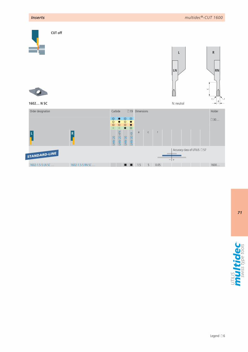
71c
arr
L R
LN RN
1602… N SC
19
30…
– –
L R
UHM
20
UHM
20
HPX
UHM
30
UHM
30
HXa c r
– +
1602-1.5-5 LN SC … 1602-1.5-5 RN SC … ¢ ¢ 1.5 5 0.05 1600…
STANDARD-LINE
Inserts
CUT off
Order designation Carbide Dimensions Holder
Accuracy class of UTILIS 57
N: neutral
Legend 6
multidec®-CUT 1600
72
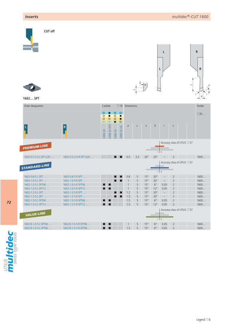
αc
a
s
β
r r
L R
L R
19
30…
– –
L R
UHM
20
UHM
20
HPX
UHM
30
UHM
30
HX
a c α β r s
– +
1602-0.5-2.5 L SPT G20 … 1602-0.5-2.5-R SPT G20 … ¢ ¢ 0.5 2.5 20° 20° – 2 1600…
– +
1602-0.8-5 L SPT … 1602-0.8-5 R SPT … ¢ ¢ 0.8 5 15° 20° – 2 1600…1602-1.0-5 L SPT … 1602-1.0-5 R SPT … ¢ ¢ 1 5 15° 20° – 2 1600…1602-1.0-5 L SPT06 … 1602-1.0-5 R SPT06 … ¢ ¢ 1 5 15° 6° 0.05 2 1600…1602-1.0-5 L SPT12 … 1602-1.0-5 R SPT12 … ¢ ¢ 1 5 15° 12° 0.05 2 1600…1602-1.2-5 L SPT … 1602-1.2-5 R SPT … ¢ ¢ 1.2 5 15° 20° – 2 1600…1602-1.5-5 L SPT … 1602-1.5-5 R SPT … ¢ ¢ 1.5 5 15° 20° – 2 1600…1602-1.5-5 L SPT06 … 1602-1.5-5 R SPT06 … ¢ ¢ 1.5 5 15° 6° 0.05 2 1600…1602-1.5-5 L SPT12 … 1602-1.5-5 R SPT12 … ¢ ¢ 1.5 5 15° 12° 0.05 2 1600…
– +
1602 B-1.0-5 L SPT06 … 1602 B-1.0-5 R SPT06 … ¢ ¢ 1 5 15° 6° 0.05 2 1600…1602 B-1.5-5 L SPT06 … 1602 B-1.5-5 R SPT06 … ¢ ¢ 1.5 5 15° 6° 0.05 2 1600…
1602… SPT
PREMIUM-LINE
VALUE-LINE
STANDARD-LINE
CUT off
Inserts
Order designation Carbide Dimensions Holder
Accuracy class of UTILIS 57
Accuracy class of UTILIS 57
Accuracy class of UTILIS 57
Legend 6
multidec®-CUT 1600
73
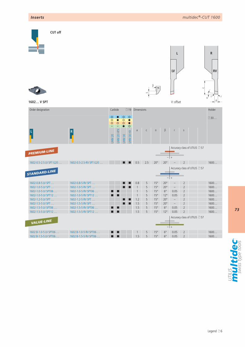
αa
s
β
r
c
r
L R
LV RV
1602… V SPT
19
30…
– –
L R
UHM
20
UHM
20
HPX
UHM
30
UHM
30
HXa c α β r s
– +
1602-0.5-2.5 LV SPT G20 … 1602-0.5-2.5-RV SPT G20 … ¢ ¢ 0.5 2.5 20° 20° – 2 1600…
– +
1602-0.8-5 LV SPT … 1602-0.8-5 RV SPT … ¢ ¢ 0.8 5 15° 20° – 2 1600…1602-1.0-5 LV SPT … 1602-1.0-5 RV SPT … ¢ ¢ 1 5 15° 20° – 2 1600…1602-1.0-5 LV SPT06 … 1602-1.0-5 RV SPT06 … ¢ ¢ 1 5 15° 6° 0.05 2 1600…1602-1.0-5 LV SPT12 … 1602-1.0-5 RV SPT12 … ¢ ¢ 1 5 15° 12° 0.05 2 1600…1602-1.2-5 LV SPT … 1602-1.2-5 RV SPT … ¢ ¢ 1.2 5 15° 20° – 2 1600…1602-1.5-5 LV SPT … 1602-1.5-5 RV SPT … ¢ ¢ 1.5 5 15° 20° – 2 1600…1602-1.5-5 LV SPT06 … 1602-1.5-5 RV SPT06 … ¢ ¢ 1.5 5 15° 6° 0.05 2 1600…1602-1.5-5 LV SPT12 … 1602-1.5-5 RV SPT12 … ¢ ¢ 1.5 5 15° 12° 0.05 2 1600…
– +
1602 B-1.0-5 LV SPT06 … 1602 B-1.0-5 RV SPT06 … ¢ ¢ 1 5 15° 6° 0.05 2 1600…1602 B-1.5-5 LV SPT06 … 1602 B-1.5-5 RV SPT06 … ¢ ¢ 1.5 5 15° 6° 0.05 2 1600…
PREMIUM-LINE
VALUE-LINE
STANDARD-LINE
Inserts
CUT off
V: offset
Order designation Carbide Dimensions Holder
Accuracy class of UTILIS 57
Accuracy class of UTILIS 57
Accuracy class of UTILIS 57
Legend 6

multidec®-CUT 1600
74
c
a
s
β
rr
L R
LN RN
1602… N SPT
19
30…
– –
L R
UHM
20
UHM
20
HPX
UHM
30
UHM
30
HX
a c r s β
– +
1602-0.5-2.5-LN SPT … 1602-0.5-2.5-RN SPT … ¢ ¢ 0.5 2.5 0.05 2 20° 1600…
– +
1602-0.8-5 LN SPT … 1602-0.8-5 RN SPT … ¢ ¢ 0.8 5 0.05 2 20° 1600…1602-1.0-5 LN SPT … 1602-1.0-5 RN SPT … ¢ ¢ 1 5 0.05 2 20° 1600…1602-1.0-5 LN SPT06 … 1602-1.0-5 RN SPT06 … ¢ ¢ 1 5 0.05 2 6° 1600…1602-1.0-5 LN SPT12 … 1602-1.0-5 RN SPT12 … ¢ ¢ 1 5 0.05 2 12° 1600…1602-1.2-5 LN SPT … 1602-1.2-5 RN SPT … ¢ ¢ 1.2 5 0.05 2 20° 1600…1602-1.5-5 LN SPT … 1602-1.5-5 RN SPT … ¢ ¢ 1.5 5 0.05 2 20° 1600…1602-1.5-5 LN SPT06 … 1602-1.5-5 RN SPT06 … ¢ ¢ 1.5 5 0.05 2 6° 1600…1602-1.5-5 LN SPT12 … 1602-1.5-5 RN SPT12 … ¢ ¢ 1.5 5 0.05 2 12° 1600…
– +
1602 B-1.0-5 LN SPT06 … 1602 B-1.0-5 RN SPT06 … ¢ ¢ 1 5 0.05 2 6° 1600…1602 B-1.5-5 LN SPT06 … 1602 B-1.5-5 RN SPT06 … ¢ ¢ 1.5 5 0.05 2 6° 1600…
PREMIUM-LINE
STANDARD-LINE
VALUE-LINE
Inserts
CUT off
Order designation Carbide Dimensions Holder
Accuracy class of UTILIS 57
Accuracy class of UTILIS 57
Accuracy class of UTILIS 57
N: neutral
Legend 6
multidec®-CUT 1600
75
α
c
ab
β
r
L R
L R
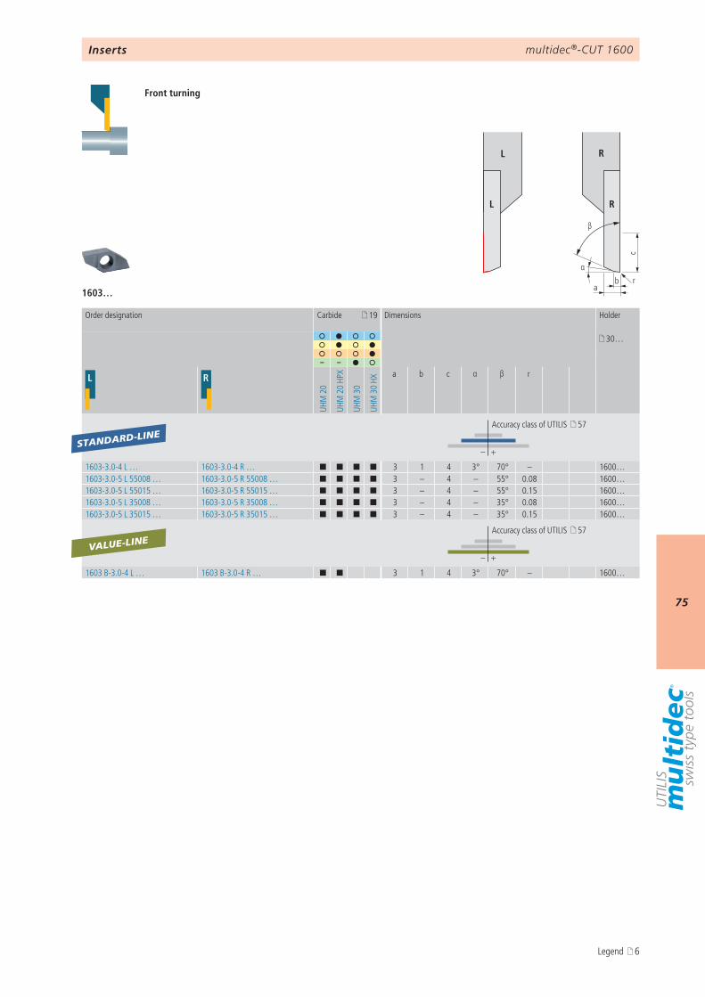
1603…
19
30…
– –
L R
UHM
20
UHM
20
HPX
UHM
30
UHM
30
HXa b c α β r
– +
1603-3.0-4 L … 1603-3.0-4 R … ¢ ¢ ¢ ¢ 3 1 4 3° 70° – 1600…1603-3.0-5 L 55008 … 1603-3.0-5 R 55008 … ¢ ¢ ¢ ¢ 3 – 4 – 55° 0.08 1600…1603-3.0-5 L 55015 … 1603-3.0-5 R 55015 … ¢ ¢ ¢ ¢ 3 – 4 – 55° 0.15 1600…1603-3.0-5 L 35008 … 1603-3.0-5 R 35008 … ¢ ¢ ¢ ¢ 3 – 4 – 35° 0.08 1600…1603-3.0-5 L 35015 … 1603-3.0-5 R 35015 … ¢ ¢ ¢ ¢ 3 – 4 – 35° 0.15 1600…
– +
1603 B-3.0-4 L … 1603 B-3.0-4 R … ¢ ¢ 3 1 4 3° 70° – 1600…
STANDARD-LINE
VALUE-LINE
Inserts
Front turning
Order designation Carbide Dimensions Holder
Accuracy class of UTILIS 57
Accuracy class of UTILIS 57
Legend 6

multidec®-CUT 1600
76c
a
β
γ
s
A – A
AA
r
L R
L R
1603… SP U…
19
30…
– –
L R
UHM
20
UHM
20
HPX
UHM
30
UHM
30
HX
a c β r s γ
– +
1603-3.0-4 L SP U55003 … 1603-3.0-4 R SP U55003 … ¢ ¢ ¢ ¢ 3 4 55° 0.03 1 12° 1600…1603-3.0-4 L SP U55008 … 1603-3.0-4 R SP U55008 … ¢ ¢ ¢ ¢ 3 4 55° 0.08 1 12° 1600…1603-3.0-4 L SP U55015 … 1603-3.0-4 R SP U55015 … ¢ ¢ ¢ ¢ 3 4 55° 0.15 1 12° 1600…1603-3.0-4 L SP U35003 … 1603-3.0-4 R SP U35003 … ¢ ¢ ¢ ¢ 3 4 35° 0.03 1 12° 1600…1603-3.0-4 L SP U35008 … 1603-3.0-4 R SP U35008 … ¢ ¢ ¢ ¢ 3 4 35° 0.08 1 12° 1600…1603-3.0-4 L SP U35015 … 1603-3.0-4 R SP U35015 … ¢ ¢ ¢ ¢ 3 4 35° 0.15 1 12° 1600…
STANDARD-LINE
Inserts
Front turning
Order designation Carbide Dimensions Holder
Accuracy class of UTILIS 57
Legend 6
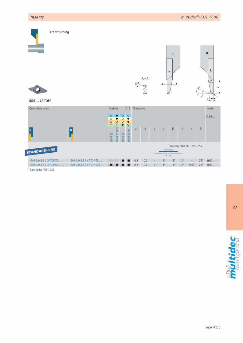
multidec®-CUT 1600
77
α
c
ab
δ
γ
β
A – A
AA
r
L R
L R
1603… CP TOP*
19
30…
– –
L R
UHM
20
UHM
20
HPX
UHM
30
UHM
30
HXa b c α β γ r δ
– +
1603-3.0-3.5 L CP TOP ZZ … 1603-3.0-3.5 R CP TOP ZZ … ¢ ¢ 0.8 0.2 4 1° 15° 2° – 25° 1600…1603-3.0-3.5 L CP TOP 003 … 1603-3.0-3.5 R CP TOP 003 … ¢ ¢ ¢ ¢ 0.8 0.2 4 1° 15° 2° 0.03 25° 1600…
STANDARD-LINE
Inserts
Front turning
Order designation Carbide Dimensions Holder
Accuracy class of UTILIS 57
* Description TOP 25
Legend 6
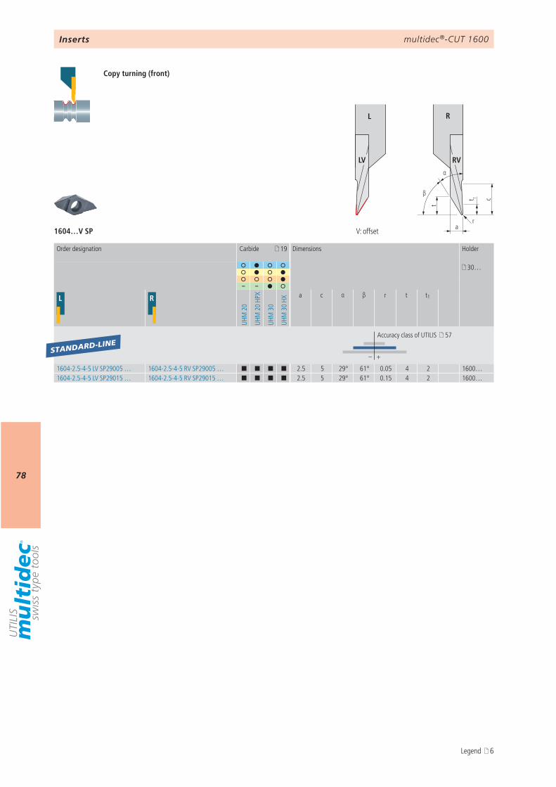
multidec®-CUT 1600
78
t
a
β
α
r
ct 1
L R
LV RV
1604…V SP
19
30…
– –
L R
UHM
20
UHM
20
HPX
UHM
30
UHM
30
HX
a c α β r t t1
– +
1604-2.5-4-5 LV SP29005 … 1604-2.5-4-5 RV SP29005 … ¢ ¢ ¢ ¢ 2.5 5 29° 61° 0.05 4 2 1600…1604-2.5-4-5 LV SP29015 … 1604-2.5-4-5 RV SP29015 … ¢ ¢ ¢ ¢ 2.5 5 29° 61° 0.15 4 2 1600…
STANDARD-LINE
Inserts
Copy turning (front)
Order designation Carbide Dimensions Holder
Accuracy class of UTILIS 57
V: offset
Legend 6

multidec®-CUT 1600
79t
a
β
α
t 1
r
c
L R
L R
1604… SP
19
30…
– –
L R
UHM
20
UHM
20
HPX
UHM
30
UHM
30
HXa c α β r t t1
– +
1604-1.25-2-3 L SP29005 … 1604-1.25-2-3 R SP29005 … ¢ ¢ ¢ ¢ 1.25 2.5 29° 61° 0.05 2 1 1600…1604-2.5-4-5 L SP29005 … 1604-2.5-4-5 R SP29005 … ¢ ¢ ¢ ¢ 2.5 5 29° 61° 0.05 4 2 1600…1604-2.5-4-5 L SP29015 … 1604-2.5-4-5 R SP29015 … ¢ ¢ ¢ ¢ 2.5 5 29° 61° 0.15 4 2 1600…
STANDARD-LINE
Inserts
Copy turning (back)
Order designation Carbide Dimensions Holder
Accuracy class of UTILIS 57
Legend 6
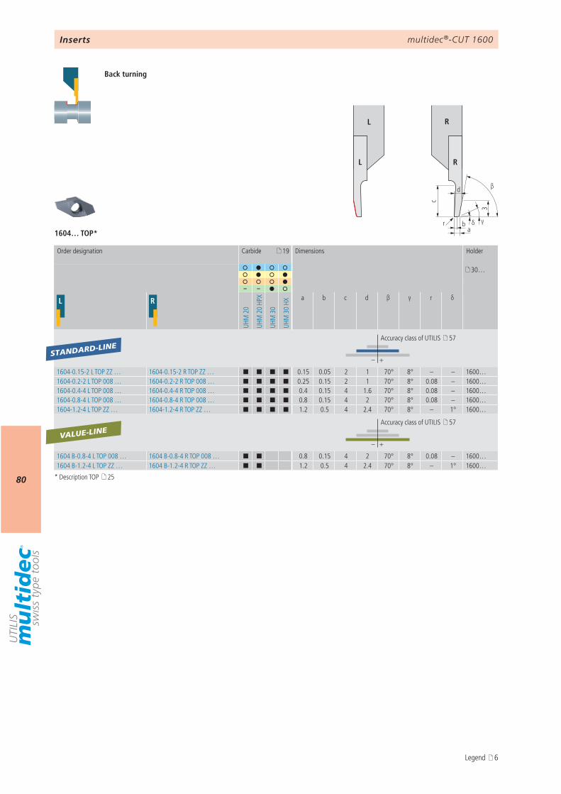
multidec®-CUT 1600
803
ab
β
c
d
γr δ
L R
L R
1604… TOP*
19
30…
– –
L R
UHM
20
UHM
20
HPX
UHM
30
UHM
30
HX
a b c d β γ r δ
– +
1604-0.15-2 L TOP ZZ … 1604-0.15-2 R TOP ZZ … ¢ ¢ ¢ ¢ 0.15 0.05 2 1 70° 8° – – 1600…1604-0.2-2 L TOP 008 … 1604-0.2-2 R TOP 008 … ¢ ¢ ¢ ¢ 0.25 0.15 2 1 70° 8° 0.08 – 1600…1604-0.4-4 L TOP 008 … 1604-0.4-4 R TOP 008 … ¢ ¢ ¢ ¢ 0.4 0.15 4 1.6 70° 8° 0.08 – 1600…1604-0.8-4 L TOP 008 … 1604-0.8-4 R TOP 008 … ¢ ¢ ¢ ¢ 0.8 0.15 4 2 70° 8° 0.08 – 1600…1604-1.2-4 L TOP ZZ … 1604-1.2-4 R TOP ZZ … ¢ ¢ ¢ ¢ 1.2 0.5 4 2.4 70° 8° – 1° 1600…
– +
1604 B-0.8-4 L TOP 008 … 1604 B-0.8-4 R TOP 008 … ¢ ¢ 0.8 0.15 4 2 70° 8° 0.08 – 1600… 1604 B-1.2-4 L TOP ZZ … 1604 B-1.2-4 R TOP ZZ … ¢ ¢ 1.2 0.5 4 2.4 70° 8° – 1° 1600…
STANDARD-LINE
VALUE-LINE
Inserts
Back turning
Order designation Carbide Dimensions Holder
Accuracy class of UTILIS 57
Accuracy class of UTILIS 57
* Description TOP 25
Legend 6
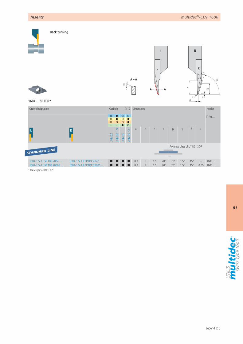
multidec®-CUT 1600
81
a
c
γ
β
α
3
b
r
A – A
AAδ
L R
L R
1604… SP TOP*
19
30…
– –
L R
UHM
20
UHM
20
HPX
UHM
30
UHM
30
HXa c b α β γ δ r
– +
1604-1.5-3 L SP TOP 20ZZ … 1604-1.5-3 R SP TOP 20ZZ … ¢ ¢ ¢ ¢ 0.3 3 1.5 20° 70° 1.5° 15° – 1600…1604-1.5-3 L SP TOP 20005 … 1604-1.5-3 R SP TOP 20005 … ¢ ¢ ¢ ¢ 0.3 3 1.5 20° 70° 1.5° 15° 0.05 1600…
STANDARD-LINE
Inserts
Back turning
Order designation Carbide Dimensions Holder
Accuracy class of UTILIS 57
* Description TOP 25
Legend 6
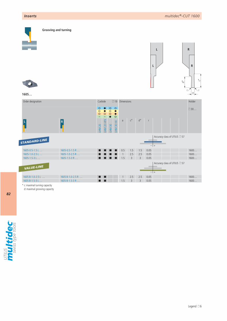
multidec®-CUT 1600
82
d* c*
arr
L R
L R
1605…
19
30…
– –
L R
UHM
20
UHM
20
HPX
UHM
30
UHM
30
HX
a c* d* r
– +
1605-0.5-1.5 L … 1605-0.5-1.5 R … ¢ ¢ ¢ ¢ 0.5 1.5 1.5 0.05 1600…1605-1.0-2.5 L … 1605-1.0-2.5 R … ¢ ¢ ¢ ¢ 1 2.5 2.5 0.05 1600…1605-1.5-3 L … 1605-1.5-3 R … ¢ ¢ ¢ ¢ 1.5 3 3 0.05 1600…
– +
1605 B-1.0-2.5 L … 1605 B-1.0-2.5 R … ¢ ¢ 1 2.5 2.5 0.05 1600…1605 B-1.5-3 L … 1605 B-1.5-3 R … ¢ ¢ 1.5 3 3 0.05 1600…
STANDARD-LINE
VALUE-LINE
Inserts
Grooving and turning
* c: maximal turning capacity d: maximal grooving capacity
Order designation Carbide Dimensions Holder
Accuracy class of UTILIS 57
Accuracy class of UTILIS 57
Legend 6
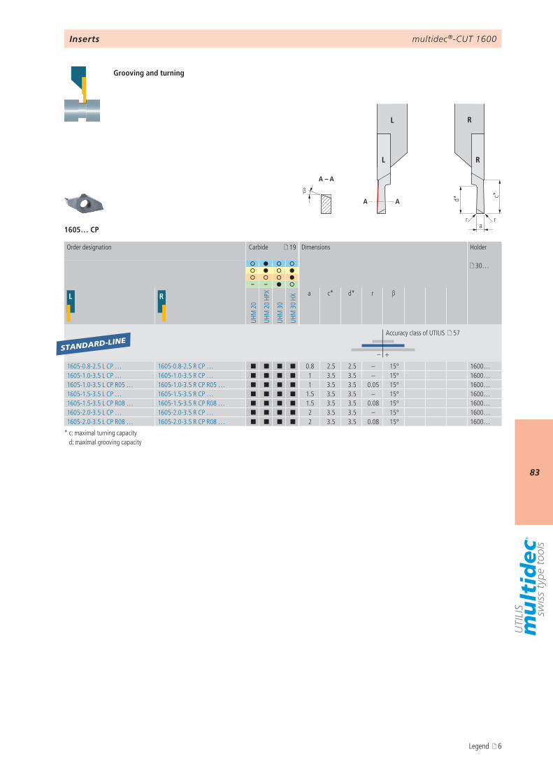
multidec®-CUT 1600
83
d* c*
arr
β
A – A
AA
L R
L R
1605… CP
19
30…
– –
L R
UHM
20
UHM
20
HPX
UHM
30
UHM
30
HXa c* d* r β
– +
1605-0.8-2.5 L CP … 1605-0.8-2.5 R CP … ¢ ¢ ¢ ¢ 0.8 2.5 2.5 – 15° 1600…1605-1.0-3.5 L CP … 1605-1.0-3.5 R CP … ¢ ¢ ¢ ¢ 1 3.5 3.5 – 15° 1600…1605-1.0-3.5 L CP R05 … 1605-1.0-3.5 R CP R05 … ¢ ¢ ¢ ¢ 1 3.5 3.5 0.05 15° 1600…1605-1.5-3.5 L CP … 1605-1.5-3.5 R CP … ¢ ¢ ¢ ¢ 1.5 3.5 3.5 – 15° 1600…1605-1.5-3.5 L CP R08 … 1605-1.5-3.5 R CP R08 … ¢ ¢ ¢ ¢ 1.5 3.5 3.5 0.08 15° 1600…1605-2.0-3.5 L CP … 1605-2.0-3.5 R CP … ¢ ¢ ¢ ¢ 2 3.5 3.5 – 15° 1600…1605-2.0-3.5 L CP R08 … 1605-2.0-3.5 R CP R08 … ¢ ¢ ¢ ¢ 2 3.5 3.5 0.08 15° 1600…
STANDARD-LINE
Inserts
Grooving and turning
* c: maximal turning capacity d: maximal grooving capacity
Order designation Carbide Dimensions Holder
Accuracy class of UTILIS 57
Legend 6
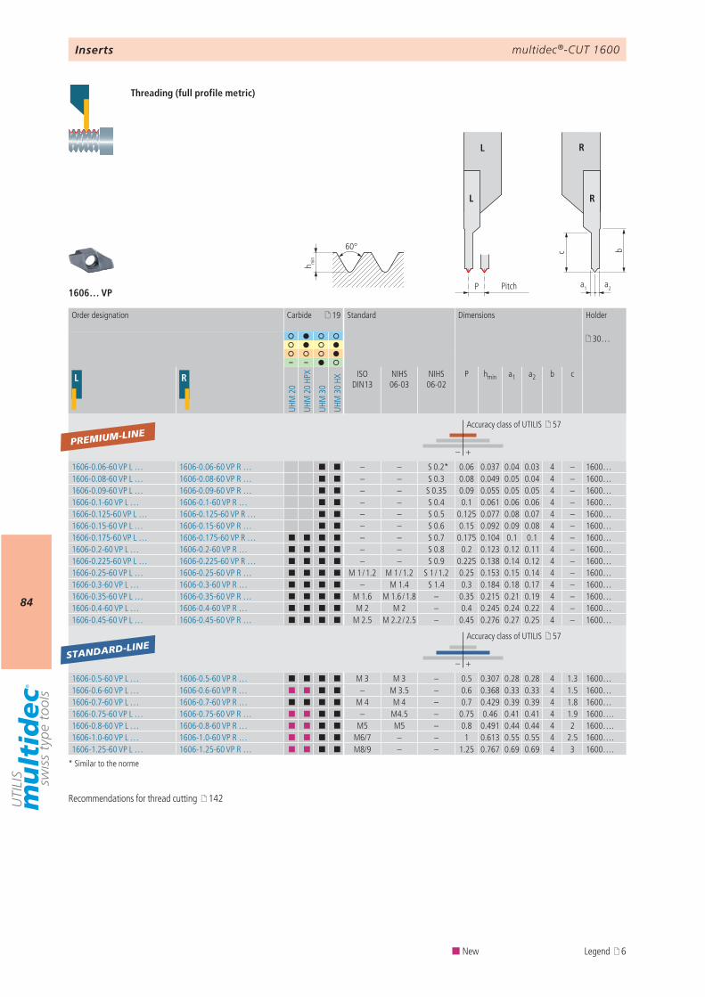
multidec®-CUT 1600
84
c
a1P
b
a2
h min
60°
L R
L R
1606… VP
19
30…
– –
L R
UHM
20
UHM
20
HPX
UHM
30
UHM
30
HX
ISO DIN13
NIHS 06-03
NIHS 06-02
P hmin a1 a2 b c
– +
1606-0.06-60 VP L … 1606-0.06-60 VP R … ¢ ¢ – – S 0.2* 0.06 0.037 0.04 0.03 4 – 1600…1606-0.08-60 VP L … 1606-0.08-60 VP R … ¢ ¢ – – S 0.3 0.08 0.049 0.05 0.04 4 – 1600…1606-0.09-60 VP L … 1606-0.09-60 VP R … ¢ ¢ – – S 0.35 0.09 0.055 0.05 0.05 4 – 1600…1606-0.1-60 VP L … 1606-0.1-60 VP R … ¢ ¢ – – S 0.4 0.1 0.061 0.06 0.06 4 – 1600…1606-0.125-60 VP L … 1606-0.125-60 VP R … ¢ ¢ – – S 0.5 0.125 0.077 0.08 0.07 4 – 1600…1606-0.15-60 VP L … 1606-0.15-60 VP R … ¢ ¢ – – S 0.6 0.15 0.092 0.09 0.08 4 – 1600…1606-0.175-60 VP L … 1606-0.175-60 VP R … ¢ ¢ ¢ ¢ – – S 0.7 0.175 0.104 0.1 0.1 4 – 1600…1606-0.2-60 VP L … 1606-0.2-60 VP R … ¢ ¢ ¢ ¢ – – S 0.8 0.2 0.123 0.12 0.11 4 – 1600…1606-0.225-60 VP L … 1606-0.225-60 VP R … ¢ ¢ ¢ ¢ – – S 0.9 0.225 0.138 0.14 0.12 4 – 1600…1606-0.25-60 VP L … 1606-0.25-60 VP R … ¢ ¢ ¢ ¢ M 1 / 1.2 M 1 / 1.2 S 1 / 1.2 0.25 0.153 0.15 0.14 4 – 1600…1606-0.3-60 VP L … 1606-0.3-60 VP R … ¢ ¢ ¢ ¢ – M 1.4 S 1.4 0.3 0.184 0.18 0.17 4 – 1600…1606-0.35-60 VP L … 1606-0.35-60 VP R … ¢ ¢ ¢ ¢ M 1.6 M 1.6 / 1.8 – 0.35 0.215 0.21 0.19 4 – 1600…1606-0.4-60 VP L … 1606-0.4-60 VP R … ¢ ¢ ¢ ¢ M 2 M 2 – 0.4 0.245 0.24 0.22 4 – 1600…1606-0.45-60 VP L … 1606-0.45-60 VP R … ¢ ¢ ¢ ¢ M 2.5 M 2.2 / 2.5 – 0.45 0.276 0.27 0.25 4 – 1600…
– +
1606-0.5-60 VP L … 1606-0.5-60 VP R … ¢ ¢ ¢ ¢ M 3 M 3 – 0.5 0.307 0.28 0.28 4 1.3 1600…1606-0.6-60 VP L … 1606-0.6-60 VP R … ¢ ¢ ¢ ¢ – M 3.5 – 0.6 0.368 0.33 0.33 4 1.5 1600…1606-0.7-60 VP L … 1606-0.7-60 VP R … ¢ ¢ ¢ ¢ M 4 M 4 – 0.7 0.429 0.39 0.39 4 1.8 1600…1606-0.75-60 VP L … 1606-0.75-60 VP R … ¢ ¢ ¢ ¢ – M4.5 – 0.75 0.46 0.41 0.41 4 1.9 1600…. 1606-0.8-60 VP L … 1606-0.8-60 VP R … ¢ ¢ ¢ ¢ M5 M5 – 0.8 0.491 0.44 0.44 4 2 1600…. 1606-1.0-60 VP L … 1606-1.0-60 VP R … ¢ ¢ ¢ ¢ M6/7 – – 1 0.613 0.55 0.55 4 2.5 1600…. 1606-1.25-60 VP L … 1606-1.25-60 VP R … ¢ ¢ ¢ ¢ M8/9 – – 1.25 0.767 0.69 0.69 4 3 1600….
PREMIUM-LINE
STANDARD-LINE
Inserts
Threading (full profile metric)
Recommendations for thread cutting 142
* Similar to the norme
Pitch
Order designation Carbide Standard Dimensions Holder
Accuracy class of UTILIS 57
Accuracy class of UTILIS 57
¢ New Legend 6
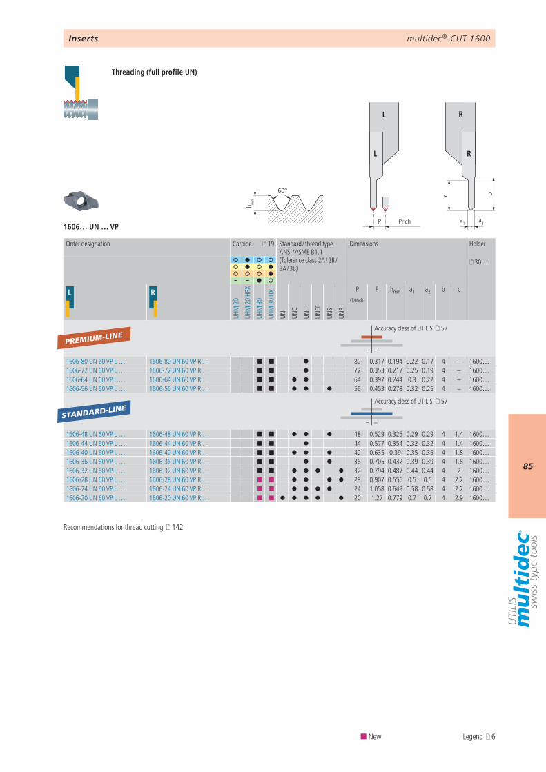
multidec®-CUT 1600
85
1606… UN … VP
c
a1P
b
a2
h min
60°
L R
L R
19
30…
– –
L R
UHM
20
UHM
20
HPX
UHM
30
UHM
30
HX
UN UNC
UNF
UNEF
UNS
UNR
P P hmin a1 a2 b c
– +
1606-80 UN 60 VP L … 1606-80 UN 60 VP R … ¢ ¢ 80 0.317 0.194 0.22 0.17 4 – 1600…1606-72 UN 60 VP L … 1606-72 UN 60 VP R … ¢ ¢ 72 0.353 0.217 0.25 0.19 4 – 1600…1606-64 UN 60 VP L.… 1606-64 UN 60 VP R … ¢ ¢ 64 0.397 0.244 0.3 0.22 4 – 1600…1606-56 UN 60 VP L … 1606-56 UN 60 VP R … ¢ ¢ 56 0.453 0.278 0.32 0.25 4 – 1600…
– +
1606-48 UN 60 VP L … 1606-48 UN 60 VP R … ¢ ¢ 48 0.529 0.325 0.29 0.29 4 1.4 1600…1606-44 UN 60 VP L … 1606-44 UN 60 VP R … ¢ ¢ 44 0.577 0.354 0.32 0.32 4 1.4 1600…1606-40 UN 60 VP L … 1606-40 UN 60 VP R … ¢ ¢ 40 0.635 0.39 0.35 0.35 4 1.8 1600…1606-36 UN 60 VP L … 1606-36 UN 60 VP R … ¢ ¢ 36 0.705 0.432 0.39 0.39 4 1.8 1600…1606-32 UN 60 VP L … 1606-32 UN 60 VP R … ¢ ¢ 32 0.794 0.487 0.44 0.44 4 2 1600…1606-28 UN 60 VP L … 1606-28 UN 60 VP R … ¢ ¢ 28 0.907 0.556 0.5 0.5 4 2.2 1600…1606-24 UN 60 VP L … 1606-24 UN 60 VP R … ¢ ¢ 24 1.058 0.649 0.58 0.58 4 2.2 1600…1606-20 UN 60 VP L … 1606-20 UN 60 VP R … ¢ ¢ 20 1.27 0.779 0.7 0.7 4 2.9 1600…
PREMIUM-LINE
STANDARD-LINE
Inserts
Threading (full profile UN)
Pitch
Order designation Carbide Standard / thread typeANSI / ASME B1.1(Tolerance class 2A / 2B / 3A / 3B)
Dimensions Holder
(T/Inch)
Accuracy class of UTILIS 57
Accuracy class of UTILIS 57
Recommendations for thread cutting 142
¢ New Legend 6
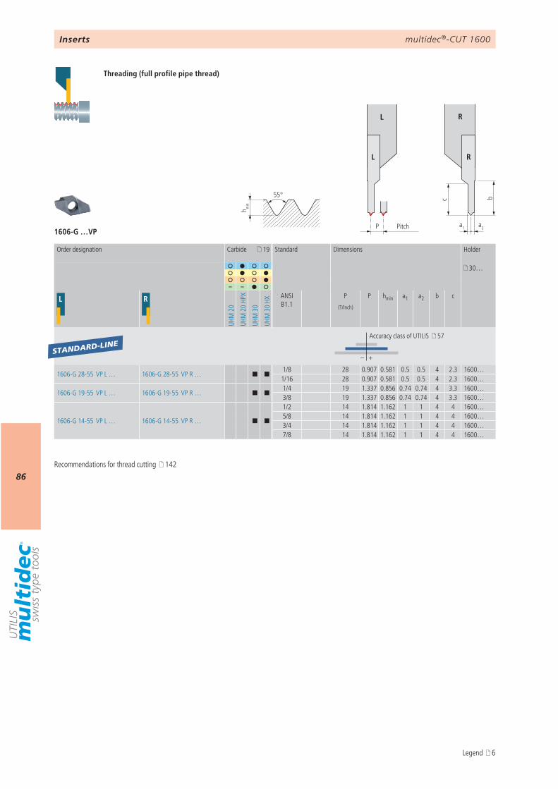
multidec®-CUT 1600
86
1606-G …VP
c
a1P
b
a2
h min
55°
L R
L R
19
30…
– –
L R
UHM
20
UHM
20
HPX
UHM
30
UHM
30
HX
ANSI B1.1
P P hmin a1 a2 b c
– +
1606-G 28-55 VP L … 1606-G 28-55 VP R … ¢ ¢1/8 28 0.907 0.581 0.5 0.5 4 2.3 1600…1/16 28 0.907 0.581 0.5 0.5 4 2.3 1600…
1606-G 19-55 VP L … 1606-G 19-55 VP R … ¢ ¢1/4 19 1.337 0.856 0.74 0.74 4 3.3 1600…3/8 19 1.337 0.856 0.74 0.74 4 3.3 1600…
1606-G 14-55 VP L … 1606-G 14-55 VP R … ¢ ¢
1/2 14 1.814 1.162 1 1 4 4 1600…5/8 14 1.814 1.162 1 1 4 4 1600…3/4 14 1.814 1.162 1 1 4 4 1600…7/8 14 1.814 1.162 1 1 4 4 1600…
STANDARD-LINE
Inserts
Threading (full profile pipe thread)
Pitch
Order designation Carbide Standard Dimensions Holder
(T/Inch)
Accuracy class of UTILIS 57
Recommendations for thread cutting 142
Legend 6
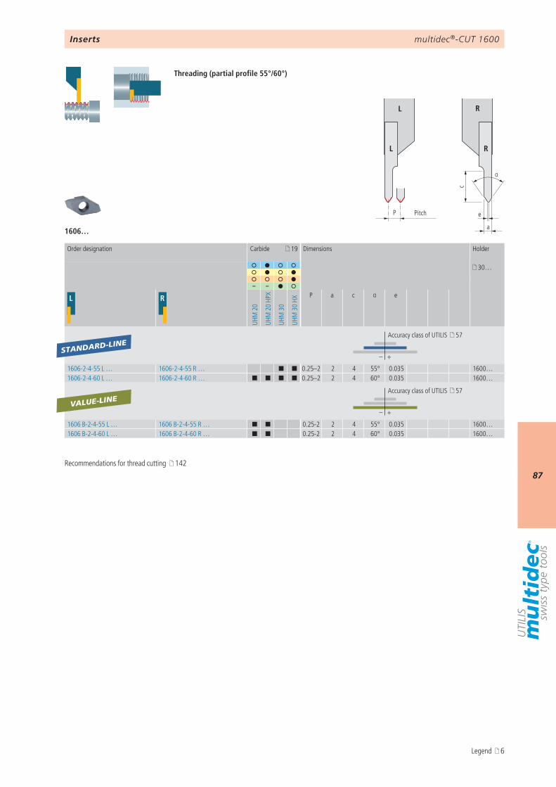
multidec®-CUT 1600
87
c
α
P e
a
L R
L R
1606…
19
30…
– –
L R
UHM
20
UHM
20
HPX
UHM
30
UHM
30
HXP a c α e
– +
1606-2-4-55 L … 1606-2-4-55 R … ¢ ¢ 0.25–2 2 4 55° 0.035 1600…1606-2-4-60 L … 1606-2-4-60 R … ¢ ¢ ¢ ¢ 0.25–2 2 4 60° 0.035 1600…
– +
1606 B-2-4-55 L … 1606 B-2-4-55 R … ¢ ¢ 0.25-2 2 4 55° 0.035 1600…1606 B-2-4-60 L … 1606 B-2-4-60 R … ¢ ¢ 0.25-2 2 4 60° 0.035 1600…
STANDARD-LINE
VALUE-LINE
Inserts
Threading (partial profile 55°/60°)
Pitch
Order designation Carbide Dimensions Holder
Accuracy class of UTILIS 57
Accuracy class of UTILIS 57
Recommendations for thread cutting 142
Legend 6
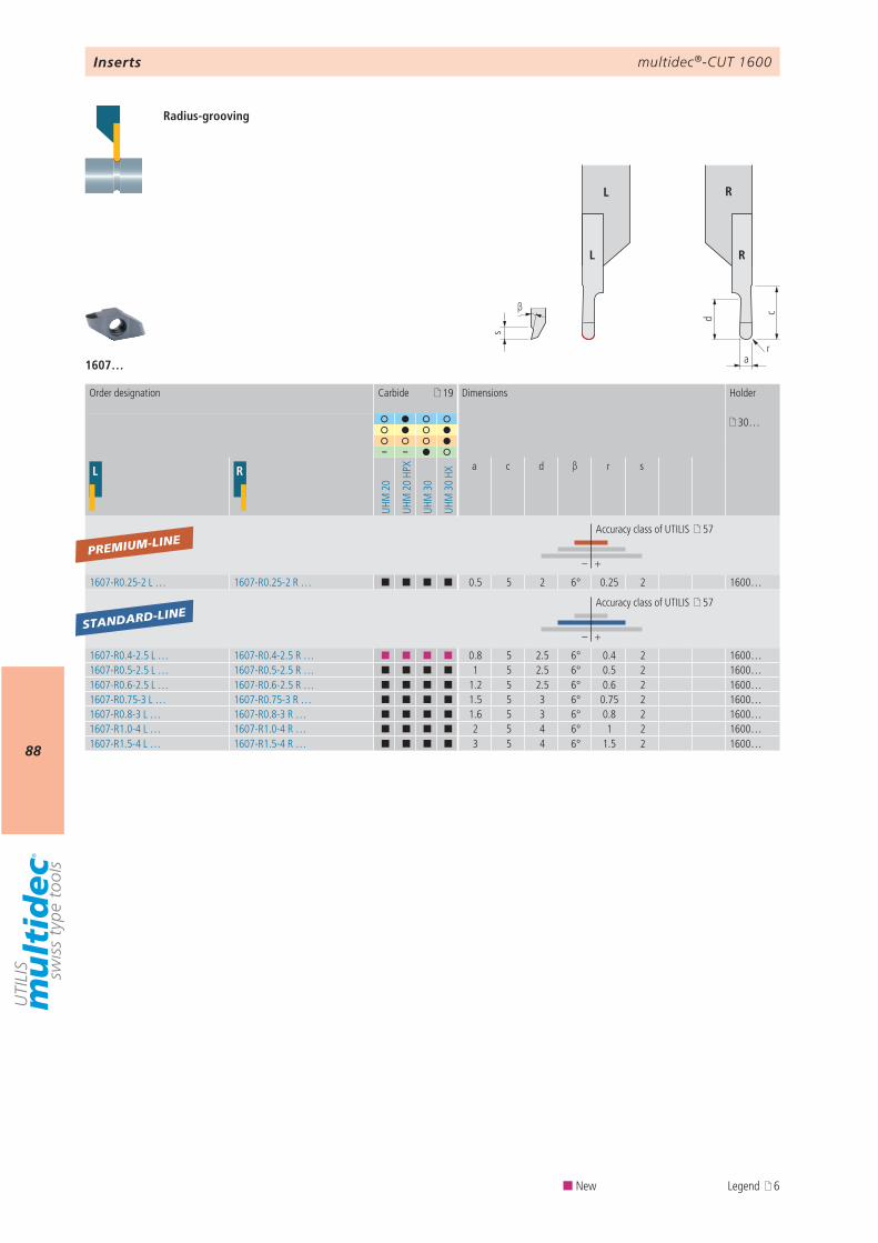
multidec®-CUT 1600
88
d c
a
s
β
r
L R
L R
1607…
19
30…
– –
L R
UHM
20
UHM
20
HPX
UHM
30
UHM
30
HX
a c d β r s
– +
1607-R0.25-2 L … 1607-R0.25-2 R … ¢ ¢ ¢ ¢ 0.5 5 2 6° 0.25 2 1600…
– +
1607-R0.4-2.5 L … 1607-R0.4-2.5 R … ¢ ¢ ¢ ¢ 0.8 5 2.5 6° 0.4 2 1600…1607-R0.5-2.5 L … 1607-R0.5-2.5 R … ¢ ¢ ¢ ¢ 1 5 2.5 6° 0.5 2 1600…1607-R0.6-2.5 L … 1607-R0.6-2.5 R … ¢ ¢ ¢ ¢ 1.2 5 2.5 6° 0.6 2 1600…1607-R0.75-3 L … 1607-R0.75-3 R … ¢ ¢ ¢ ¢ 1.5 5 3 6° 0.75 2 1600…1607-R0.8-3 L … 1607-R0.8-3 R … ¢ ¢ ¢ ¢ 1.6 5 3 6° 0.8 2 1600…1607-R1.0-4 L … 1607-R1.0-4 R … ¢ ¢ ¢ ¢ 2 5 4 6° 1 2 1600…1607-R1.5-4 L … 1607-R1.5-4 R … ¢ ¢ ¢ ¢ 3 5 4 6° 1.5 2 1600…
PREMIUM-LINE
STANDARD-LINE
Inserts
Radius-grooving
Order designation Carbide Dimensions Holder
Accuracy class of UTILIS 57
Accuracy class of UTILIS 57
¢ New Legend 6
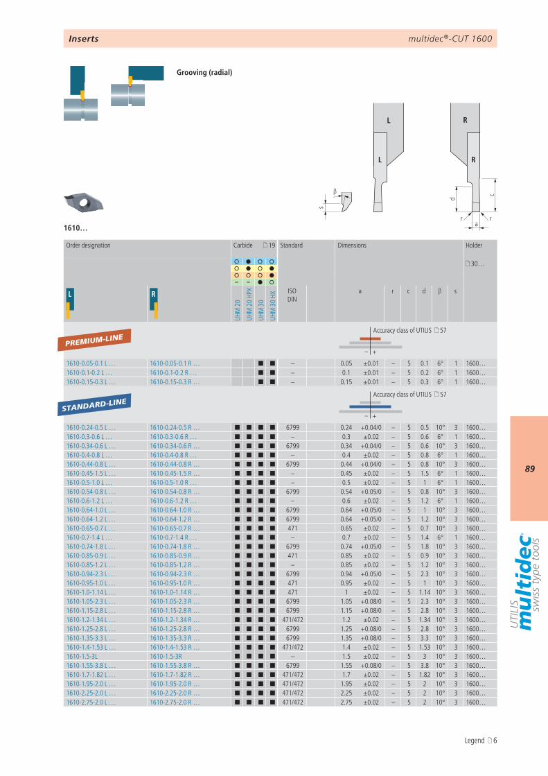
multidec®-CUT 1600
89
d c
ar r
s
β
L R
L R
1610…
19
30…
– –
L R
UHM
20
UHM
20
HPX
UHM
30
UHM
30
HX
ISO DIN
a r c d β s
– +
1610-0.05-0.1 L … 1610-0.05-0.1 R … ¢ ¢ – 0.05 ±0.01 – 5 0.1 6° 1 1600…1610-0.1-0.2 L … 1610-0.1-0.2 R … ¢ ¢ – 0.1 ±0.01 – 5 0.2 6° 1 1600…1610-0.15-0.3 L … 1610-0.15-0.3 R … ¢ ¢ – 0.15 ±0.01 – 5 0.3 6° 1 1600…
– +
1610-0.24-0.5 L … 1610-0.24-0.5 R … ¢ ¢ ¢ ¢ 6799 0.24 +0.04/0 – 5 0.5 10° 3 1600…1610-0.3-0.6 L … 1610-0.3-0.6 R … ¢ ¢ ¢ ¢ – 0.3 ±0.02 – 5 0.6 6° 1 1600…1610-0.34-0.6 L … 1610-0.34-0.6 R … ¢ ¢ ¢ ¢ 6799 0.34 +0.04/0 – 5 0.6 10° 3 1600…1610-0.4-0.8 L … 1610-0.4-0.8 R … ¢ ¢ ¢ ¢ – 0.4 ±0.02 – 5 0.8 6° 1 1600…1610-0.44-0.8 L … 1610-0.44-0.8 R … ¢ ¢ ¢ ¢ 6799 0.44 +0.04/0 – 5 0.8 10° 3 1600…1610-0.45-1.5 L … 1610-0.45-1.5 R … ¢ ¢ ¢ ¢ – 0.45 ±0.02 – 5 1.5 6° 1 1600…1610-0.5-1.0 L … 1610-0.5-1.0 R … ¢ ¢ ¢ ¢ – 0.5 ±0.02 – 5 1 6° 1 1600…1610-0.54-0.8 L … 1610-0.54-0.8 R … ¢ ¢ ¢ ¢ 6799 0.54 +0.05/0 – 5 0.8 10° 3 1600…1610-0.6-1.2 L … 1610-0.6-1.2 R … ¢ ¢ ¢ ¢ – 0.6 ±0.02 – 5 1.2 6° 1 1600…1610-0.64-1.0 L … 1610-0.64-1.0 R … ¢ ¢ ¢ ¢ 6799 0.64 +0.05/0 – 5 1 10° 3 1600…1610-0.64-1.2 L … 1610-0.64-1.2 R … ¢ ¢ ¢ ¢ 6799 0.64 +0.05/0 – 5 1.2 10° 3 1600…1610-0.65-0.7 L … 1610-0.65-0.7 R … ¢ ¢ ¢ ¢ 471 0.65 ±0.02 – 5 0.7 10° 3 1600…1610-0.7-1.4 L … 1610-0.7-1.4 R … ¢ ¢ ¢ ¢ – 0.7 ±0.02 – 5 1.4 6° 1 1600…1610-0.74-1.8 L … 1610-0.74-1.8 R … ¢ ¢ ¢ ¢ 6799 0.74 +0.05/0 – 5 1.8 10° 3 1600…1610-0.85-0.9 L … 1610-0.85-0.9 R … ¢ ¢ ¢ ¢ 471 0.85 ±0.02 – 5 0.9 10° 3 1600…1610-0.85-1.2 L … 1610-0.85-1.2 R … ¢ ¢ ¢ ¢ – 0.85 ±0.02 – 5 1.2 10° 3 1600…1610-0.94-2.3 L … 1610-0.94-2.3 R … ¢ ¢ ¢ ¢ 6799 0.94 +0.05/0 – 5 2.3 10° 3 1600…1610-0.95-1.0 L … 1610-0.95-1.0 R … ¢ ¢ ¢ ¢ 471 0.95 ±0.02 – 5 1 10° 3 1600…1610-1.0-1.14 L … 1610-1.0-1.14 R … ¢ ¢ ¢ ¢ 471 1 ±0.02 – 5 1.14 10° 3 1600…1610-1.05-2.3 L … 1610-1.05-2.3 R … ¢ ¢ ¢ ¢ 6799 1.05 +0.08/0 – 5 2.3 10° 3 1600…1610-1.15-2.8 L … 1610-1.15-2.8 R … ¢ ¢ ¢ ¢ 6799 1.15 +0.08/0 – 5 2.8 10° 3 1600…1610-1.2-1.34 L … 1610-1.2-1.34 R … ¢ ¢ ¢ ¢ 471/472 1.2 ±0.02 – 5 1.34 10° 3 1600…1610-1.25-2.8 L … 1610-1.25-2.8 R … ¢ ¢ ¢ ¢ 6799 1.25 +0.08/0 – 5 2.8 10° 3 1600…1610-1.35-3.3 L … 1610-1.35-3.3 R … ¢ ¢ ¢ ¢ 6799 1.35 +0.08/0 – 5 3.3 10° 3 1600…1610-1.4-1.53 L … 1610-1.4-1.53 R … ¢ ¢ ¢ ¢ 471/472 1.4 ±0.02 – 5 1.53 10° 3 1600…1610-1.5-3L 1610-1.5-3R ¢ ¢ ¢ ¢ – 1.5 ±0.02 – 5 3 10° 3 1600…1610-1.55-3.8 L … 1610-1.55-3.8 R … ¢ ¢ ¢ ¢ 6799 1.55 +0.08/0 – 5 3.8 10° 3 1600…1610-1.7-1.82 L … 1610-1.7-1.82 R … ¢ ¢ ¢ ¢ 471/472 1.7 ±0.02 – 5 1.82 10° 3 1600…1610-1.95-2.0 L … 1610-1.95-2.0 R … ¢ ¢ ¢ ¢ 471/472 1.95 ±0.02 – 5 2 10° 3 1600…1610-2.25-2.0 L … 1610-2.25-2.0 R … ¢ ¢ ¢ ¢ 471/472 2.25 ±0.02 – 5 2 10° 3 1600…1610-2.75-2.0 L … 1610-2.75-2.0 R … ¢ ¢ ¢ ¢ 471/472 2.75 ±0.02 – 5 2 10° 3 1600…
PREMIUM-LINE
STANDARD-LINE
Inserts
Grooving (radial)
Order designation Carbide Standard Dimensions Holder
Accuracy class of UTILIS 57
Accuracy class of UTILIS 57
Legend 6
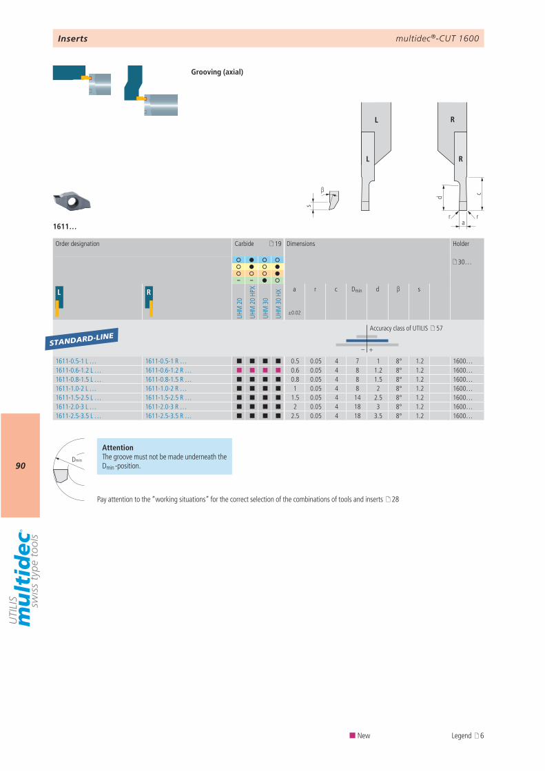
multidec®-CUT 1600
90
d c
a
s
β
rr
L R
L R
1611…
19
30…
– –
L R
UHM
20
UHM
20
HPX
UHM
30
UHM
30
HX
a
±0.02
r c Dmin d β s
– +
1611-0.5-1 L … 1611-0.5-1 R … ¢ ¢ ¢ ¢ 0.5 0.05 4 7 1 8° 1.2 1600…1611-0.6-1.2 L … 1611-0.6-1.2 R … ¢ ¢ ¢ ¢ 0.6 0.05 4 8 1.2 8° 1.2 1600…1611-0.8-1.5 L … 1611-0.8-1.5 R … ¢ ¢ ¢ ¢ 0.8 0.05 4 8 1.5 8° 1.2 1600…1611-1.0-2 L … 1611-1.0-2 R … ¢ ¢ ¢ ¢ 1 0.05 4 8 2 8° 1.2 1600…1611-1.5-2.5 L … 1611-1.5-2.5 R … ¢ ¢ ¢ ¢ 1.5 0.05 4 14 2.5 8° 1.2 1600…1611-2.0-3 L … 1611-2.0-3 R … ¢ ¢ ¢ ¢ 2 0.05 4 18 3 8° 1.2 1600…1611-2.5-3.5 L … 1611-2.5-3.5 R … ¢ ¢ ¢ ¢ 2.5 0.05 4 18 3.5 8° 1.2 1600…
STANDARD-LINE
Dmin
Inserts
Grooving (axial)
Order designation Carbide Dimensions Holder
Accuracy class of UTILIS 57
AttentionThe groove must not be made underneath the Dmin -position.
Pay attention to the “working situations” for the correct selection of the combinations of tools and inserts 28
¢ New Legend 6
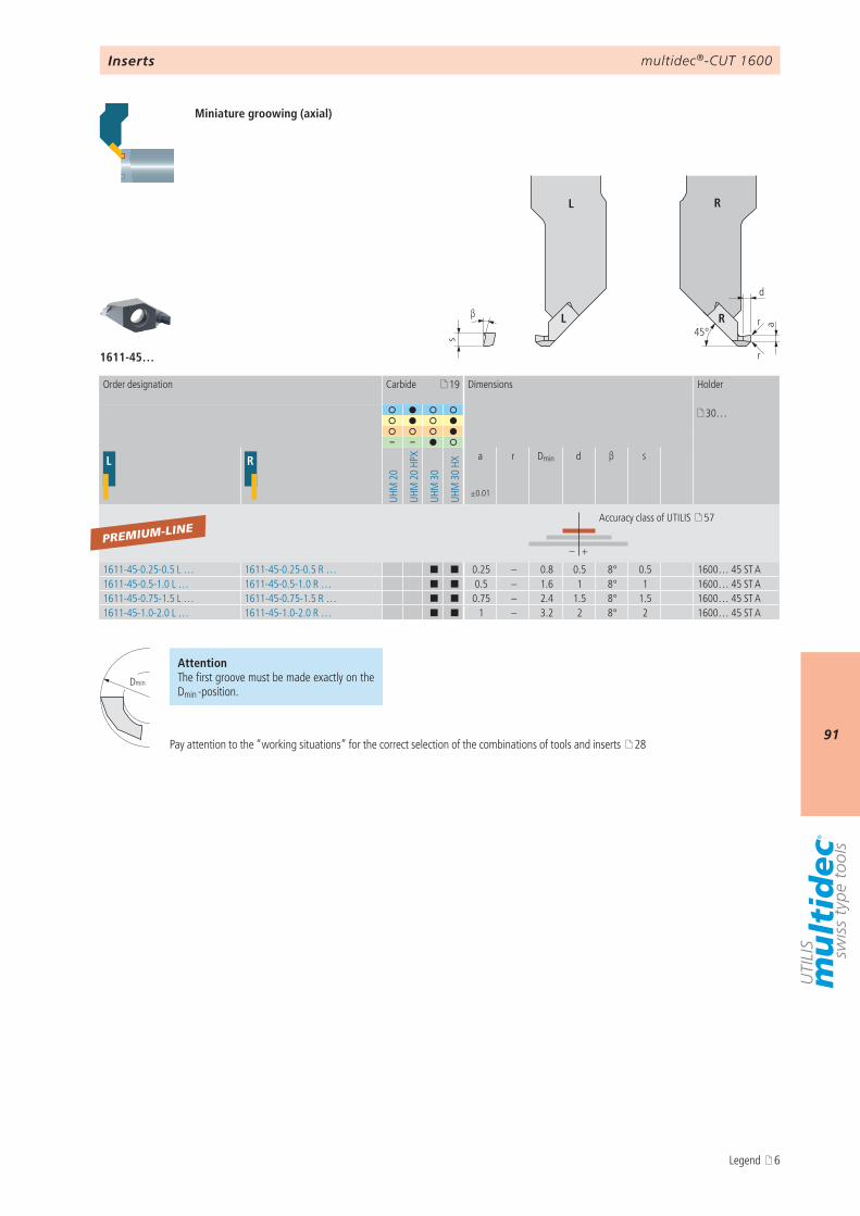
multidec®-CUT 1600
91
d
r
r
s
β
a
45°
L R
L R
1611-45…
19
30…
– –
L R
UHM
20
UHM
20
HPX
UHM
30
UHM
30
HXa
±0.01
r Dmin d β s
– +
1611-45-0.25-0.5 L … 1611-45-0.25-0.5 R … ¢ ¢ 0.25 – 0.8 0.5 8° 0.5 1600… 45 ST A1611-45-0.5-1.0 L … 1611-45-0.5-1.0 R … ¢ ¢ 0.5 – 1.6 1 8° 1 1600… 45 ST A1611-45-0.75-1.5 L … 1611-45-0.75-1.5 R … ¢ ¢ 0.75 – 2.4 1.5 8° 1.5 1600… 45 ST A1611-45-1.0-2.0 L … 1611-45-1.0-2.0 R … ¢ ¢ 1 – 3.2 2 8° 2 1600… 45 ST A
PREMIUM-LINE
Dmin
Inserts
Miniature groowing (axial)
Order designation Carbide Dimensions Holder
Accuracy class of UTILIS 57
AttentionThe first groove must be made exactly on the Dmin -position.
Pay attention to the “working situations” for the correct selection of the combinations of tools and inserts 28
Legend 6
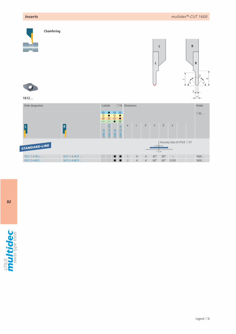
multidec®-CUT 1600
92
1612…
c
e
α
d
α
a
β
L R
L R
19
30…
– –
L R
UHM
20
UHM
20
HPX
UHM
30
UHM
30
HX
a c d α β e
– +
1612-1-4-45 L … 1612-1-4-45 R … ¢ ¢ 1 4 4 45° 90° – 1600…1612-2-4-60 L … 1612-2-4-60 R … ¢ ¢ 2 4 4 60° 60° 0.035 1600…
STANDARD-LINE
Inserts
Chamfering
Order designation Carbide Dimensions Holder
Accuracy class of UTILIS 57
Legend 6
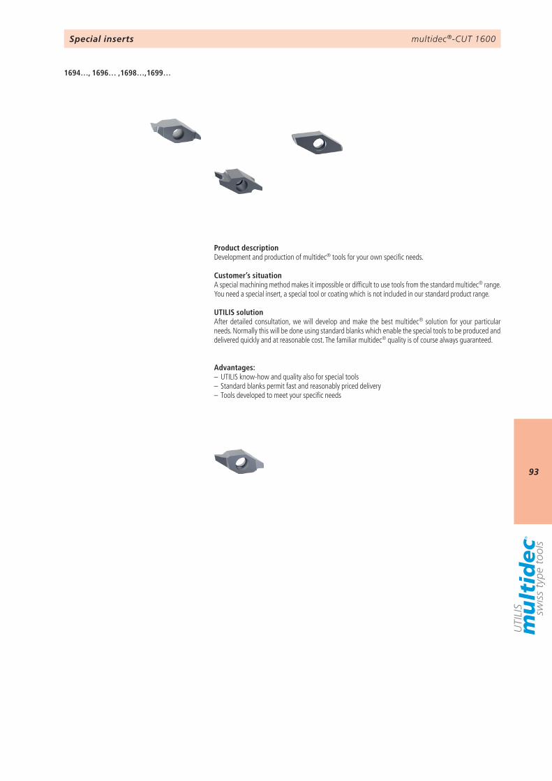
multidec®-CUT 1600
93
1694…, 1696… ,1698…,1699…
Special inserts
Product descriptionDevelopment and production of multidec® tools for your own specific needs.
Customer’s situationA special machining method makes it impossible or difficult to use tools from the standard multidec® range. You need a special insert, a special tool or coating which is not included in our standard product range.
UTILIS solutionAfter detailed consultation, we will develop and make the best multidec® solution for your particular needs. Normally this will be done using standard blanks which enable the special tools to be produced and delivered quickly and at reasonable cost. The familiar multidec® quality is of course always guaranteed.
Advantages:– UTILIS know-how and quality also for special tools– Standard blanks permit fast and reasonably priced delivery– Tools developed to meet your specific needs
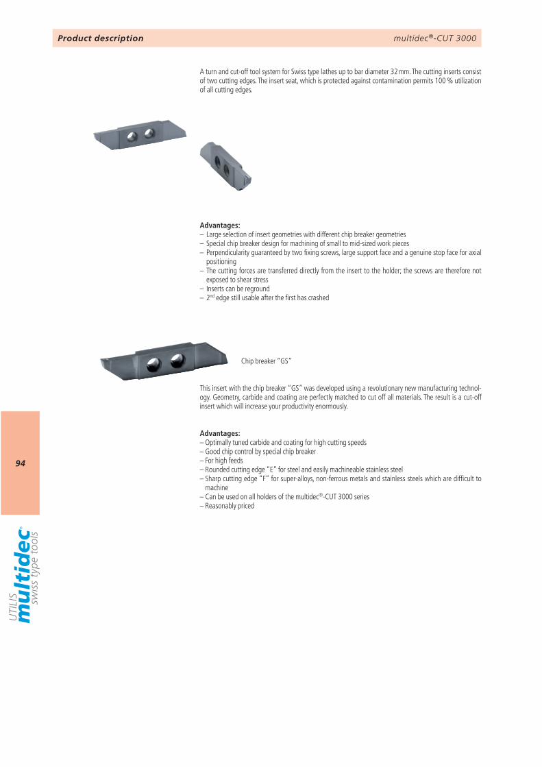
multidec®-CUT 3000
94
Product description
A turn and cut-off tool system for Swiss type lathes up to bar diameter 32 mm. The cutting inserts consist of two cutting edges. The insert seat, which is protected against contamination permits 100 % utilization of all cutting edges.
Advantages:– Large selection of insert geometries with different chip breaker geometries– Special chip breaker design for machining of small to mid-sized work pieces– Perpendicularity guaranteed by two fixing screws, large support face and a genuine stop face for axial
positioning– The cutting forces are transferred directly from the insert to the holder; the screws are therefore not
exposed to shear stress– Inserts can be reground– 2nd edge still usable after the first has crashed
Chip breaker “GS”
This insert with the chip breaker “GS” was developed using a revolutionary new manufacturing technol-ogy. Geometry, carbide and coating are perfectly matched to cut off all materials. The result is a cut-off insert which will increase your productivity enormously.
Advantages:– Optimally tuned carbide and coating for high cutting speeds– Good chip control by special chip breaker– For high feeds– Rounded cutting edge “E” for steel and easily machineable stainless steel– Sharp cutting edge “F” for super-alloys, non-ferrous metals and stainless steels which are difficult to
machine– Can be used on all holders of the multidec®-CUT 3000 series– Reasonably priced
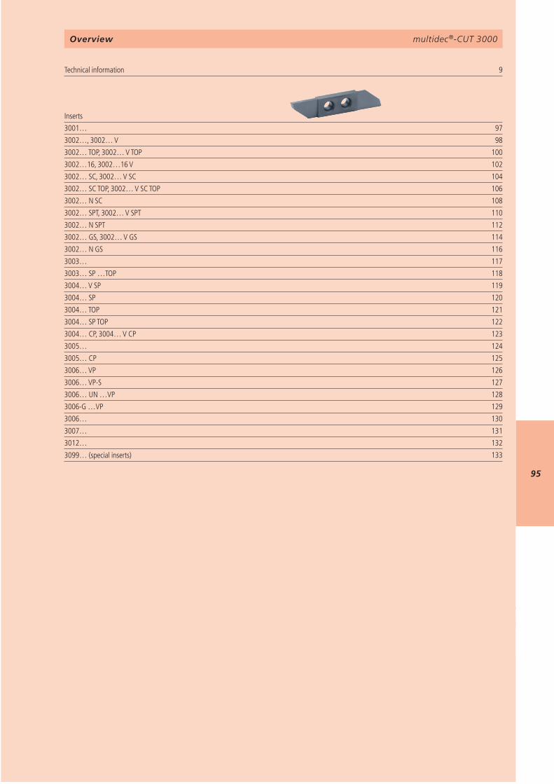
multidec®-CUT 3000
95
9 3001… 973002…, 3002… V 983002… TOP, 3002… V TOP 1003002…16, 3002…16 V 1023002… SC, 3002… V SC 1043002… SC TOP, 3002… V SC TOP 1063002… N SC 1083002… SPT, 3002… V SPT 1103002… N SPT 1123002… GS, 3002… V GS 1143002… N GS 1163003… 1173003… SP …TOP 1183004… V SP 1193004… SP 1203004… TOP 1213004… SP TOP 1223004… CP, 3004… V CP 1233005… 1243005… CP 1253006… VP 1263006… VP-S 1273006… UN …VP 1283006-G …VP 1293006… 1303007… 1313012… 132 133
multidec®-CUT 3000
Technical information Inserts
3099… (special inserts)
Overview

multidec®-CUT 3000
96
AttentionPlease note the legend 6…
Notes
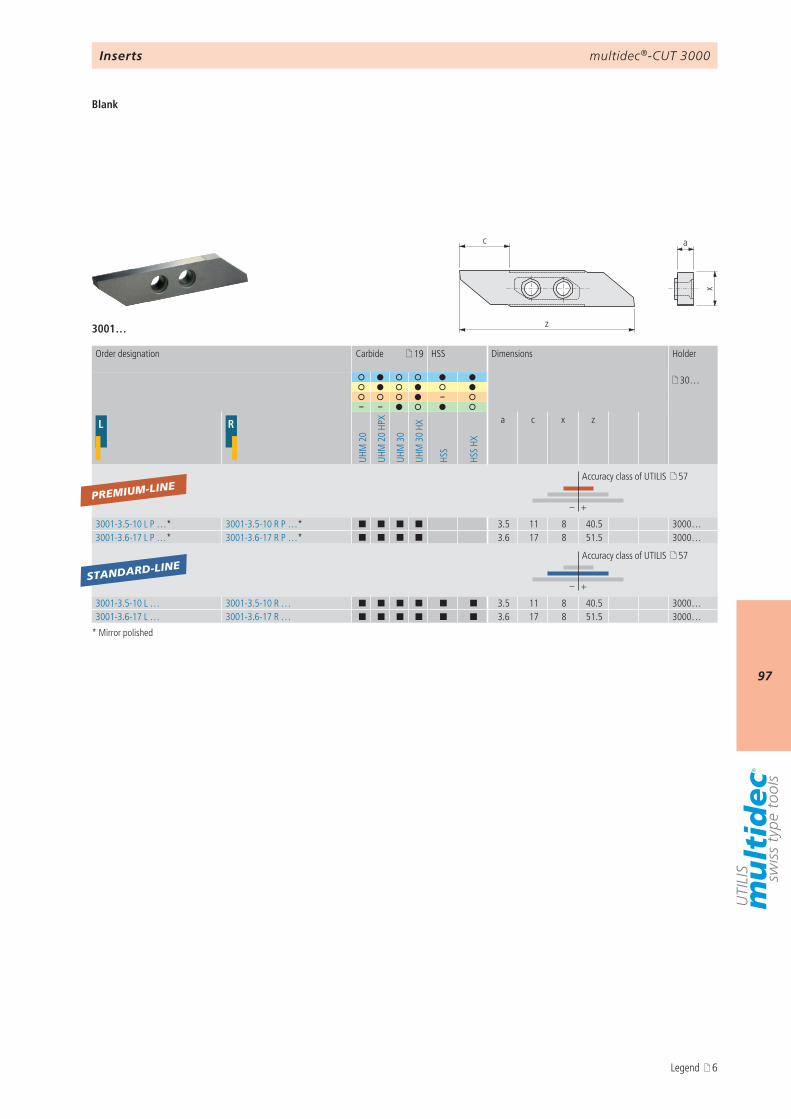
multidec®-CUT 3000
97
c
z
x
a
3001…
19
30…
–– –
L R
UHM
20
UHM
20
HPX
UHM
30
UHM
30
HX
HSS
HSS
HX
a c x z
– +
3001-3.5-10 L P …* 3001-3.5-10 R P …* ¢ ¢ ¢ ¢ 3.5 11 8 40.5 3000…3001-3.6-17 L P …* 3001-3.6-17 R P …* ¢ ¢ ¢ ¢ 3.6 17 8 51.5 3000…
– +
3001-3.5-10 L … 3001-3.5-10 R … ¢ ¢ ¢ ¢ ¢ ¢ 3.5 11 8 40.5 3000…3001-3.6-17 L … 3001-3.6-17 R … ¢ ¢ ¢ ¢ ¢ ¢ 3.6 17 8 51.5 3000…
PREMIUM-LINE
STANDARD-LINE
Inserts
Blank
* Mirror polished
Order designation Carbide HSS Dimensions Holder
Accuracy class of UTILIS 57
Accuracy class of UTILIS 57
Legend 6
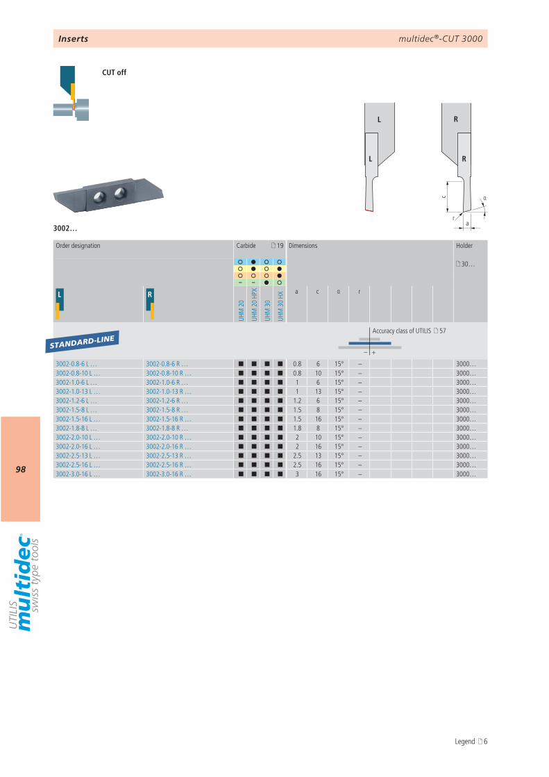
multidec®-CUT 3000
98
αc
ar
L R
L R
3002…
19
30…
– –
L R
UHM
20
UHM
20
HPX
UHM
30
UHM
30
HX
a c α r
– +
3002-0.8-6 L … 3002-0.8-6 R … ¢ ¢ ¢ ¢ 0.8 6 15° – 3000…3002-0.8-10 L … 3002-0.8-10 R … ¢ ¢ ¢ ¢ 0.8 10 15° – 3000…3002-1.0-6 L … 3002-1.0-6 R … ¢ ¢ ¢ ¢ 1 6 15° – 3000…3002-1.0-13 L … 3002-1.0-13 R … ¢ ¢ ¢ ¢ 1 13 15° – 3000…3002-1.2-6 L … 3002-1.2-6 R … ¢ ¢ ¢ ¢ 1.2 6 15° – 3000…3002-1.5-8 L … 3002-1.5-8 R … ¢ ¢ ¢ ¢ 1.5 8 15° – 3000…3002-1.5-16 L … 3002-1.5-16 R … ¢ ¢ ¢ ¢ 1.5 16 15° – 3000…3002-1.8-8 L … 3002-1.8-8 R … ¢ ¢ ¢ ¢ 1.8 8 15° – 3000…3002-2.0-10 L … 3002-2.0-10 R … ¢ ¢ ¢ ¢ 2 10 15° – 3000…3002-2.0-16 L … 3002-2.0-16 R … ¢ ¢ ¢ ¢ 2 16 15° – 3000…3002-2.5-13 L … 3002-2.5-13 R … ¢ ¢ ¢ ¢ 2.5 13 15° – 3000…3002-2.5-16 L … 3002-2.5-16 R … ¢ ¢ ¢ ¢ 2.5 16 15° – 3000…3002-3.0-16 L … 3002-3.0-16 R … ¢ ¢ ¢ ¢ 3 16 15° – 3000…
STANDARD-LINE
Inserts
CUT off
Order designation Carbide Dimensions Holder
Accuracy class of UTILIS 57
Legend 6
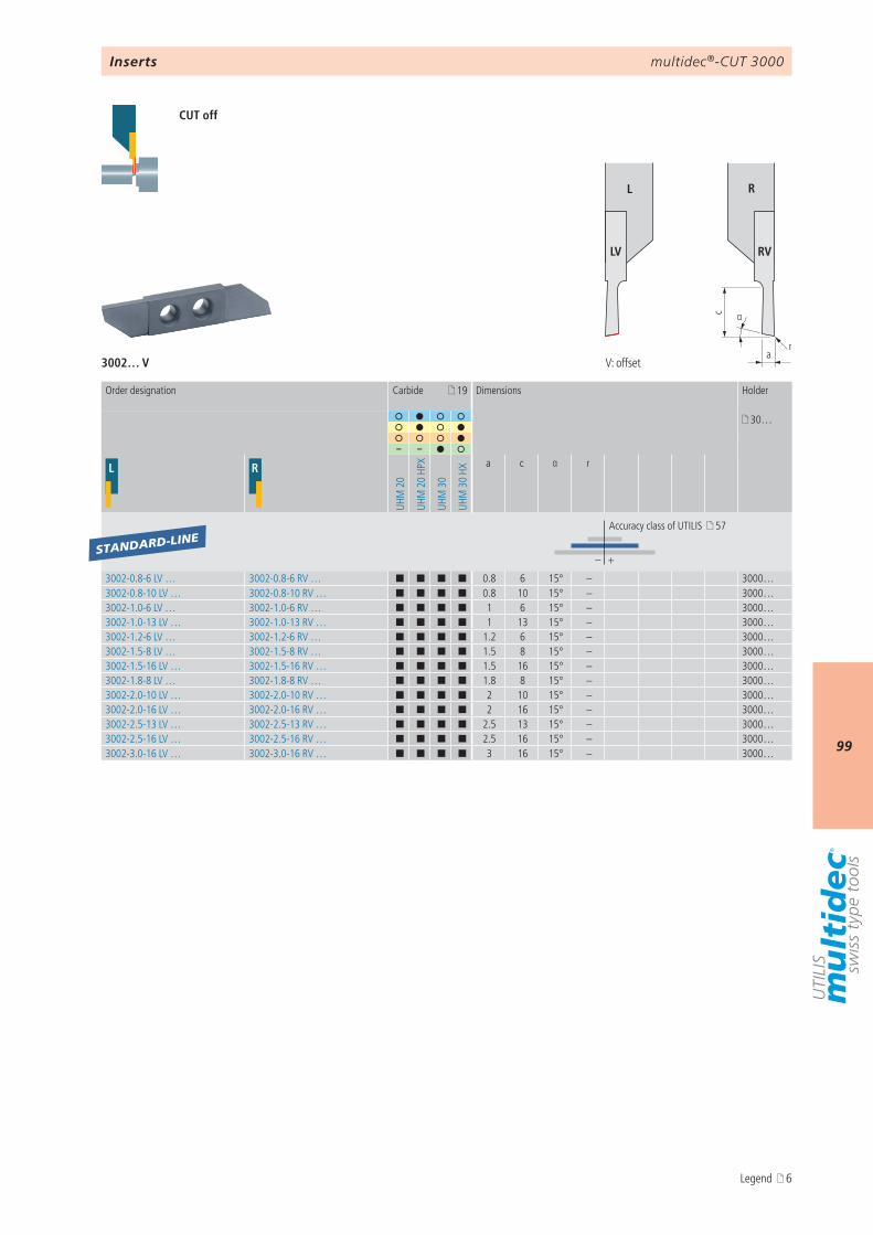
multidec®-CUT 3000
99
r
αc
a
L R
LV RV
3002… V
19
30…
– –
L R
UHM
20
UHM
20
HPX
UHM
30
UHM
30
HXa c α r
– +
3002-0.8-6 LV … 3002-0.8-6 RV … ¢ ¢ ¢ ¢ 0.8 6 15° – 3000…3002-0.8-10 LV … 3002-0.8-10 RV … ¢ ¢ ¢ ¢ 0.8 10 15° – 3000…3002-1.0-6 LV … 3002-1.0-6 RV … ¢ ¢ ¢ ¢ 1 6 15° – 3000…3002-1.0-13 LV … 3002-1.0-13 RV … ¢ ¢ ¢ ¢ 1 13 15° – 3000…3002-1.2-6 LV … 3002-1.2-6 RV … ¢ ¢ ¢ ¢ 1.2 6 15° – 3000…3002-1.5-8 LV … 3002-1.5-8 RV … ¢ ¢ ¢ ¢ 1.5 8 15° – 3000…3002-1.5-16 LV … 3002-1.5-16 RV … ¢ ¢ ¢ ¢ 1.5 16 15° – 3000…3002-1.8-8 LV … 3002-1.8-8 RV … ¢ ¢ ¢ ¢ 1.8 8 15° – 3000…3002-2.0-10 LV … 3002-2.0-10 RV … ¢ ¢ ¢ ¢ 2 10 15° – 3000…3002-2.0-16 LV … 3002-2.0-16 RV … ¢ ¢ ¢ ¢ 2 16 15° – 3000…3002-2.5-13 LV … 3002-2.5-13 RV … ¢ ¢ ¢ ¢ 2.5 13 15° – 3000…3002-2.5-16 LV … 3002-2.5-16 RV … ¢ ¢ ¢ ¢ 2.5 16 15° – 3000…3002-3.0-16 LV … 3002-3.0-16 RV … ¢ ¢ ¢ ¢ 3 16 15° – 3000…
STANDARD-LINE
Inserts
CUT off
V: offset
Order designation Carbide Dimensions Holder
Accuracy class of UTILIS 57
Legend 6
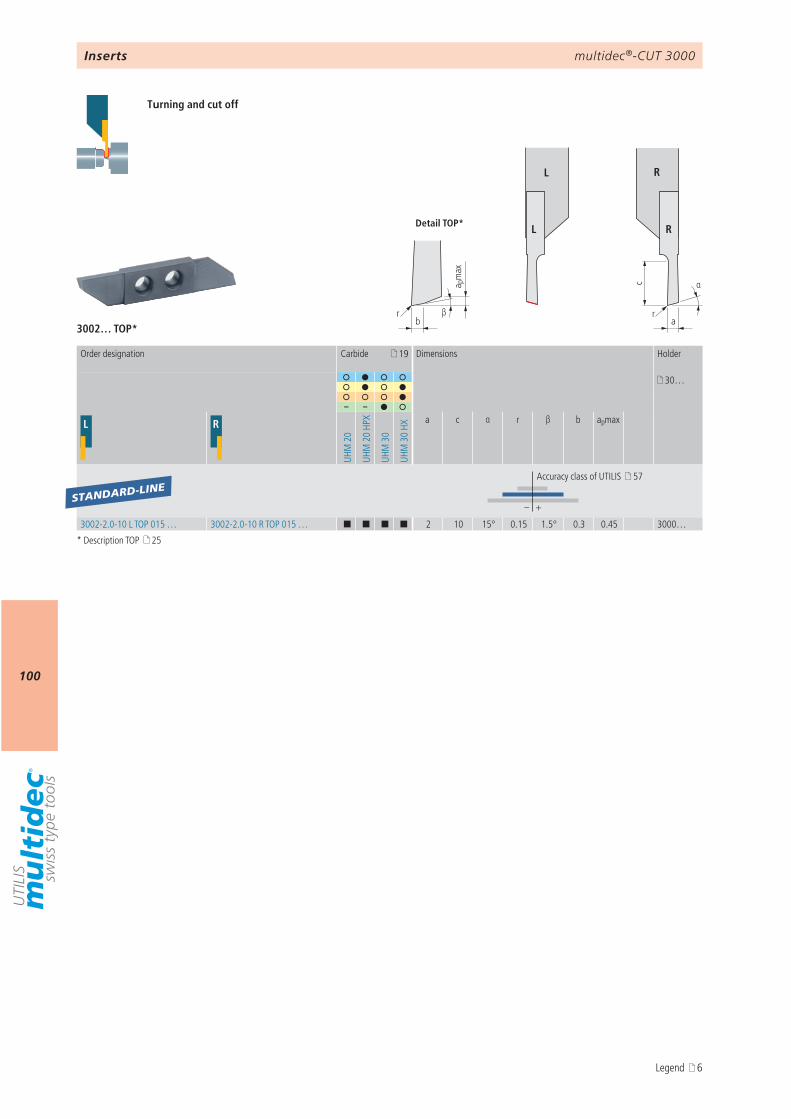
multidec®-CUT 3000
100
αc
ra
βb
a pm
ax
Detail TOP*
r
L R
L R
3002… TOP*
19
30…
– –
L R
UHM
20
UHM
20
HPX
UHM
30
UHM
30
HX
a c α r β b apmax
– +
3002-2.0-10 L TOP 015 … 3002-2.0-10 R TOP 015 … ¢ ¢ ¢ ¢ 2 10 15° 0.15 1.5° 0.3 0.45 3000…
STANDARD-LINE
Inserts
Turning and cut off
Order designation Carbide Dimensions Holder
Accuracy class of UTILIS 57
* Description TOP 25
Legend 6
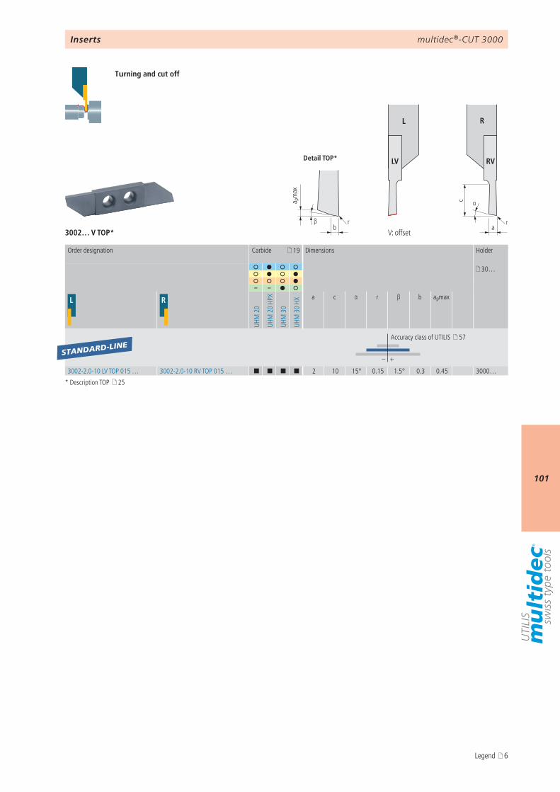
multidec®-CUT 3000
101
r
αc
arβ
b
a pm
ax
Detail TOP*
L R
LV RV
3002… V TOP*
19
30…
– –
L R
UHM
20
UHM
20
HPX
UHM
30
UHM
30
HXa c α r β b apmax
– +
3002-2.0-10 LV TOP 015 … 3002-2.0-10 RV TOP 015 … ¢ ¢ ¢ ¢ 2 10 15° 0.15 1.5° 0.3 0.45 3000…
STANDARD-LINE
Inserts
Turning and cut off
V: offset
Order designation Carbide Dimensions Holder
Accuracy class of UTILIS 57
* Description TOP 25
Legend 6
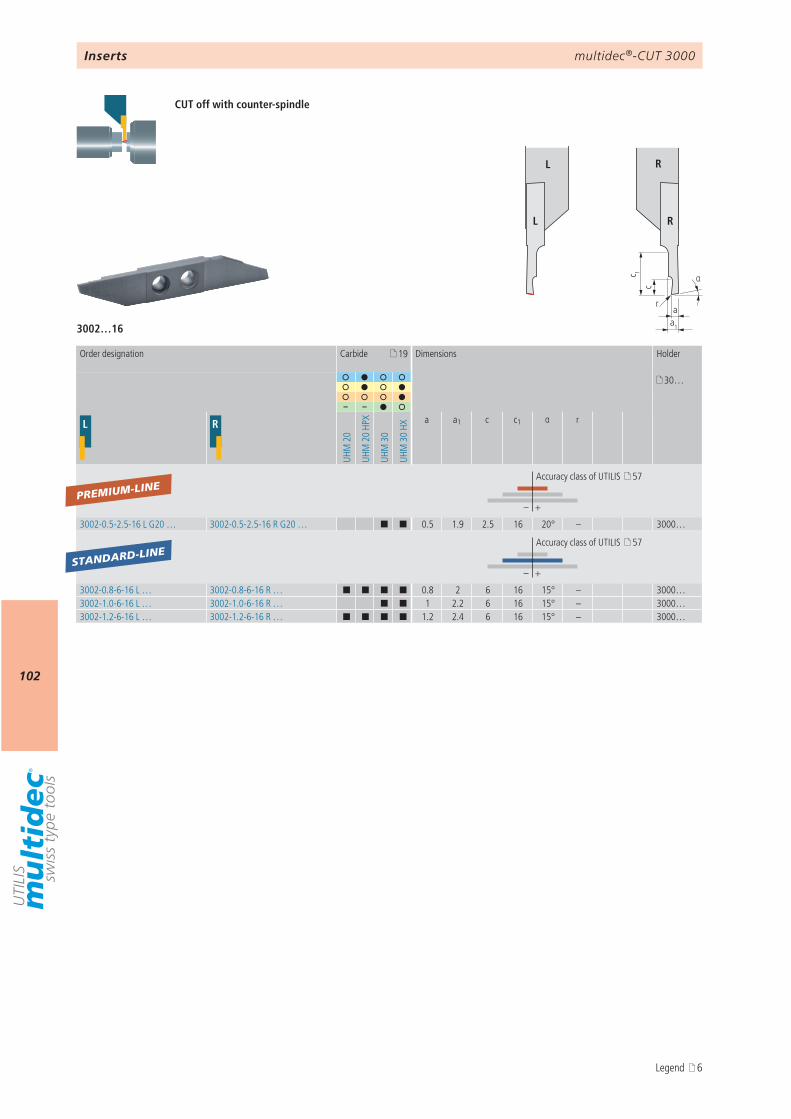
multidec®-CUT 3000
102
αc 1
aa1
c
r
L R
L R
3002…16
19
30…
– –
L R
UHM
20
UHM
20
HPX
UHM
30
UHM
30
HX
a a1 c c1 α r
– +
3002-0.5-2.5-16 L G20 … 3002-0.5-2.5-16 R G20 … ¢ ¢ 0.5 1.9 2.5 16 20° – 3000…
– +
3002-0.8-6-16 L … 3002-0.8-6-16 R … ¢ ¢ ¢ ¢ 0.8 2 6 16 15° – 3000…3002-1.0-6-16 L … 3002-1.0-6-16 R … ¢ ¢ 1 2.2 6 16 15° – 3000…3002-1.2-6-16 L … 3002-1.2-6-16 R … ¢ ¢ ¢ ¢ 1.2 2.4 6 16 15° – 3000…
PREMIUM-LINE
STANDARD-LINE
Inserts
CUT off with counter-spindle
Order designation Carbide Dimensions Holder
Accuracy class of UTILIS 57
Accuracy class of UTILIS 57
Legend 6
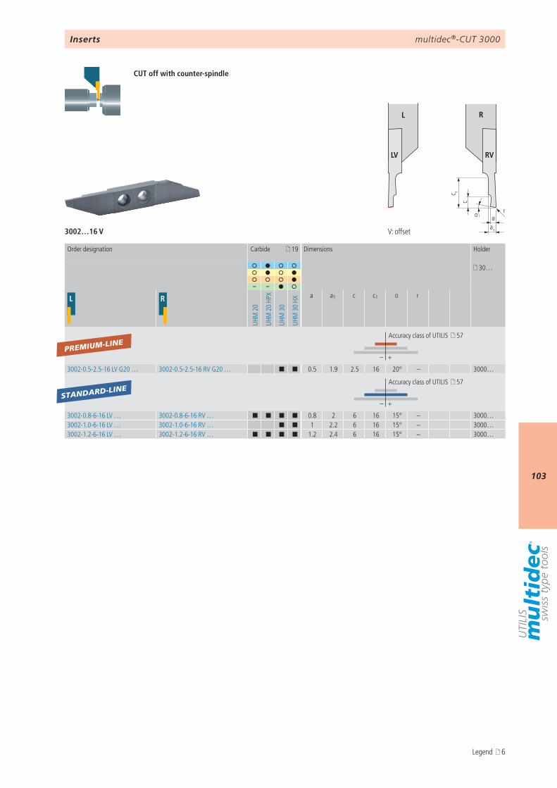
multidec®-CUT 3000
103
α ra
a1
c 1
c
L R
LV RV
3002…16 V
19
30…
– –
L R
UHM
20
UHM
20
HPX
UHM
30
UHM
30
HXa a1 c c1 α r
– +
3002-0.5-2.5-16 LV G20 … 3002-0.5-2.5-16 RV G20 … ¢ ¢ 0.5 1.9 2.5 16 20° – 3000…
– +
3002-0.8-6-16 LV … 3002-0.8-6-16 RV … ¢ ¢ ¢ ¢ 0.8 2 6 16 15° – 3000…3002-1.0-6-16 LV … 3002-1.0-6-16 RV … ¢ ¢ 1 2.2 6 16 15° – 3000…3002-1.2-6-16 LV … 3002-1.2-6-16 RV … ¢ ¢ ¢ ¢ 1.2 2.4 6 16 15° – 3000…
PREMIUM-LINE
STANDARD-LINE
Inserts
CUT off with counter-spindle
V: offset
Order designation Carbide Dimensions Holder
Accuracy class of UTILIS 57
Accuracy class of UTILIS 57
Legend 6
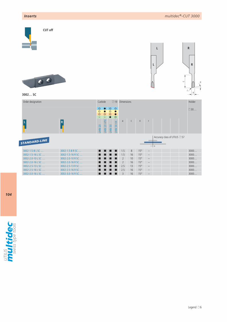
multidec®-CUT 3000
104
αc
ar
L R
L R
3002… SC
19
30…
– –
L R
UHM
20
UHM
20
HPX
UHM
30
UHM
30
HX
a c α r
– +
3002-1.5-8 L SC … 3002-1.5-8 R SC … ¢ ¢ ¢ ¢ 1.5 8 15° – 3000…3002-1.5-16 L SC … 3002-1.5-16 R SC … ¢ ¢ ¢ ¢ 1.5 16 15° – 3000…3002-2.0-10 L SC … 3002-2.0-10 R SC … ¢ ¢ ¢ ¢ 2 10 15° – 3000…3002-2.0-16 L SC … 3002-2.0-16 R SC … ¢ ¢ ¢ ¢ 2 16 15° – 3000…3002-2.5-13 L SC … 3002-2.5-13 R SC … ¢ ¢ ¢ ¢ 2.5 13 15° – 3000…3002-2.5-16 L SC … 3002-2.5-16 R SC … ¢ ¢ ¢ ¢ 2.5 16 15° – 3000…3002-3.0-16 L SC … 3002-3.0-16 R SC … ¢ ¢ ¢ ¢ 3 16 15° – 3000…
STANDARD-LINE
Inserts
CUT off
Order designation Carbide Dimensions Holder
Accuracy class of UTILIS 57
Legend 6
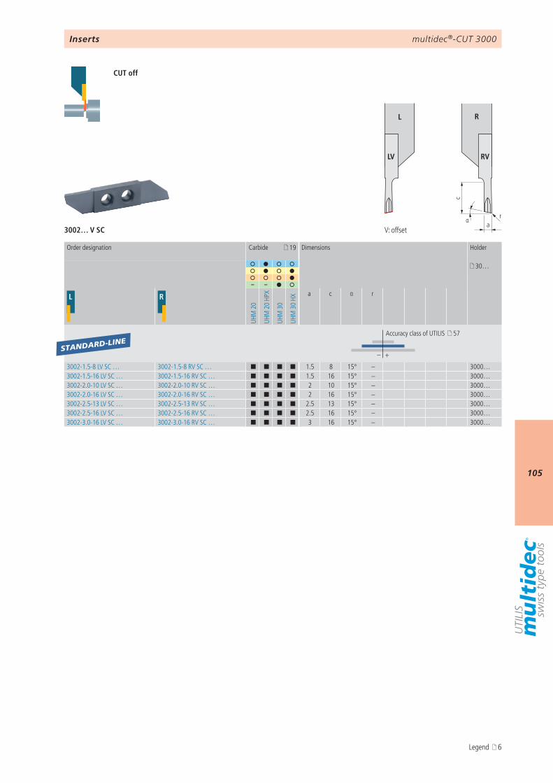
multidec®-CUT 3000
105
αa
r
c
L R
LV RV
3002… V SC
19
30…
– –
L R
UHM
20
UHM
20
HPX
UHM
30
UHM
30
HXa c α r
– +
3002-1.5-8 LV SC … 3002-1.5-8 RV SC … ¢ ¢ ¢ ¢ 1.5 8 15° – 3000…3002-1.5-16 LV SC … 3002-1.5-16 RV SC … ¢ ¢ ¢ ¢ 1.5 16 15° – 3000…3002-2.0-10 LV SC … 3002-2.0-10 RV SC … ¢ ¢ ¢ ¢ 2 10 15° – 3000…3002-2.0-16 LV SC … 3002-2.0-16 RV SC … ¢ ¢ ¢ ¢ 2 16 15° – 3000…3002-2.5-13 LV SC … 3002-2.5-13 RV SC … ¢ ¢ ¢ ¢ 2.5 13 15° – 3000…3002-2.5-16 LV SC … 3002-2.5-16 RV SC … ¢ ¢ ¢ ¢ 2.5 16 15° – 3000…3002-3.0-16 LV SC … 3002-3.0-16 RV SC … ¢ ¢ ¢ ¢ 3 16 15° – 3000…
STANDARD-LINE
Inserts
CUT off
V: offset
Order designation Carbide Dimensions Holder
Accuracy class of UTILIS 57
Legend 6

multidec®-CUT 3000
106
αc
arr β
b
a pm
ax
Detail TOP*
L R
L R
3002… SC TOP*
19
30…
– –
L R
UHM
20
UHM
20
HPX
UHM
30
UHM
30
HX
a c α r β b apmax
– +
3002-2.0-10 L SC TOP 015 … 3002-2.0-10 R SC TOP 015 … ¢ ¢ ¢ ¢ 2 10 15° 0.15 1.5° 0.3 0.45 3000…
STANDARD-LINE
Inserts
Turning and cut off
Order designation Carbide Dimensions Holder
Accuracy class of UTILIS 57
* Description TOP 25
Legend 6

multidec®-CUT 3000
107
αa
r
c
rβb
a pm
ax
Detail TOP*
L R
LV RV
3002… V SC TOP*
19
30…
– –
L R
UHM
20
UHM
20
HPX
UHM
30
UHM
30
HXa c α r β b apmax
– +
3002-2.0-10 LV SC TOP 015 … 3002-2.0-10 RV SC TOP 015 … ¢ ¢ ¢ ¢ 2 10 15° 0.15 1.5° 0.3 0.45 3000…
STANDARD-LINE
Inserts
Turning and cut off
V: offset
Order designation Carbide Dimensions Holder
Accuracy class of UTILIS 57
* Description TOP 25
Legend 6

multidec®-CUT 3000
108
c
arr
L R
LN RN
3002… N SC
19
30…
– –
L R
UHM
20
UHM
20
HPX
UHM
30
UHM
30
HX
a c r
– +
3002-1.5-10 LN SC … 3002-1.5-10 RN SC … ¢ ¢ ¢ ¢ 1.5 10 0.08 3000…3002-1.5-16 LN SC … 3002-1.5-16 RN SC … ¢ ¢ ¢ ¢ 1.5 16 0.08 3000…3002-2.0-10 LN SC … 3002-2.0-10 RN SC … ¢ ¢ ¢ ¢ 2 10 0.08 3000…3002-2.0-16 LN SC … 3002-2.0-16 RN SC … ¢ ¢ ¢ ¢ 2 16 0.08 3000…3002-2.5-13 LN SC … 3002-2.5-13 RN SC … ¢ ¢ ¢ ¢ 2.5 13 0.08 3000…3002-2.5-16 LN SC … 3002-2.5-16 RN SC … ¢ ¢ ¢ ¢ 2.5 16 0.08 3000…3002-3.0-16 LN SC … 3002-3.0-16 RN SC … ¢ ¢ ¢ ¢ 3 16 0.08 3000…
STANDARD-LINE
Inserts
CUT off
Order designation Carbide Dimensions Holder
Accuracy class of UTILIS 57
N: neutral
Legend 6
multidec®-CUT 3000
109
AttentionPlease note the legend 6…
Notes
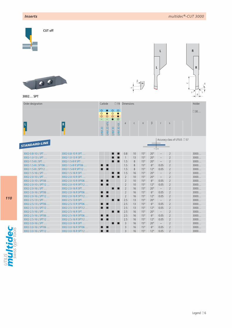
multidec®-CUT 3000
110
αc
a
s
β
r r
L R
L R
3002… SPT
19
30…
– –
L R
UHM
20
UHM
20
HPX
UHM
30
UHM
30
HX
a c α β r s
– +
3002-0.8-10 L SPT … 3002-0.8-10 R SPT … ¢ ¢ 0.8 10 15° 20° – 2 3000…3002-1.0-13 L SPT … 3002-1.0-13 R SPT … ¢ ¢ 1 13 15° 20° – 2 3000…3002-1.5-8 L SPT … 3002-1.5-8 R SPT … ¢ ¢ 1.5 8 15° 20° – 2 3000…3002-1.5-8 L SPT06 … 3002-1.5-8 R SPT06 … ¢ ¢ 1.5 8 15° 6° 0.05 2 3000…3002-1.5-8 L SPT12 … 3002-1.5-8 R SPT12 … ¢ ¢ 1.5 8 15° 12° 0.05 2 3000…3002-1.5-16 L SPT … 3002-1.5-16 R SPT … ¢ ¢ 1.5 16 15° 20° – 2 3000…3002-2.0-10 L SPT … 3002-2.0-10 R SPT … ¢ ¢ 2 10 15° 20° – 2 3000…3002-2.0-10 L SPT06 … 3002-2.0-10 R SPT06 … ¢ ¢ 2 10 15° 6° 0.05 2 3000…3002-2.0-10 L SPT12 … 3002-2.0-10 R SPT12 … ¢ ¢ 2 10 15° 12° 0.05 2 3000…3002-2.0-16 L SPT … 3002-2.0-16 R SPT … ¢ ¢ 2 16 15° 20° – 2 3000…3002-2.0-16 L SPT06 … 3002-2.0-16 R SPT06 … ¢ ¢ 2 16 15° 6° 0.05 2 3000…3002-2.0-16 L SPT12 … 3002-2.0-16 R SPT12 … ¢ ¢ 2 16 15° 12° 0.05 2 3000…3002-2.5-13 L SPT … 3002-2.5-13 R SPT … ¢ ¢ 2.5 13 15° 20° – 2 3000…3002-2.5-13 L SPT06 … 3002-2.5-13 R SPT06 … ¢ ¢ 2.5 13 15° 6° 0.05 2 3000…3002-2.5-13 L SPT12 … 3002-2.5-13 R SPT12 … ¢ ¢ 2.5 13 15° 12° 0.05 2 3000…3002-2.5-16 L SPT … 3002-2.5-16 R SPT … ¢ ¢ 2.5 16 15° 20° – 2 3000…3002-2.5-16 L SPT06 … 3002-2.5-16 R SPT06 … ¢ ¢ 2.5 16 15° 6° 0.05 2 3000…3002-2.5-16 L SPT12 … 3002-2.5-16 R SPT12 … ¢ ¢ 2.5 16 15° 12° 0.05 2 3000…3002-3.0-16 L SPT … 3002-3.0-16 R SPT … ¢ ¢ 3 16 15° 20° – 2 3000…3002-3.0-16 L SPT06 … 3002-3.0-16 R SPT06 … ¢ ¢ 3 16 15° 6° 0.05 2 3000…3002-3.0-16 L SPT12 … 3002-3.0-16 R SPT12 … ¢ ¢ 3 16 15° 12° 0.05 2 3000…
STANDARD-LINE
Inserts
CUT off
Order designation Carbide Dimensions Holder
Accuracy class of UTILIS 57
Legend 6
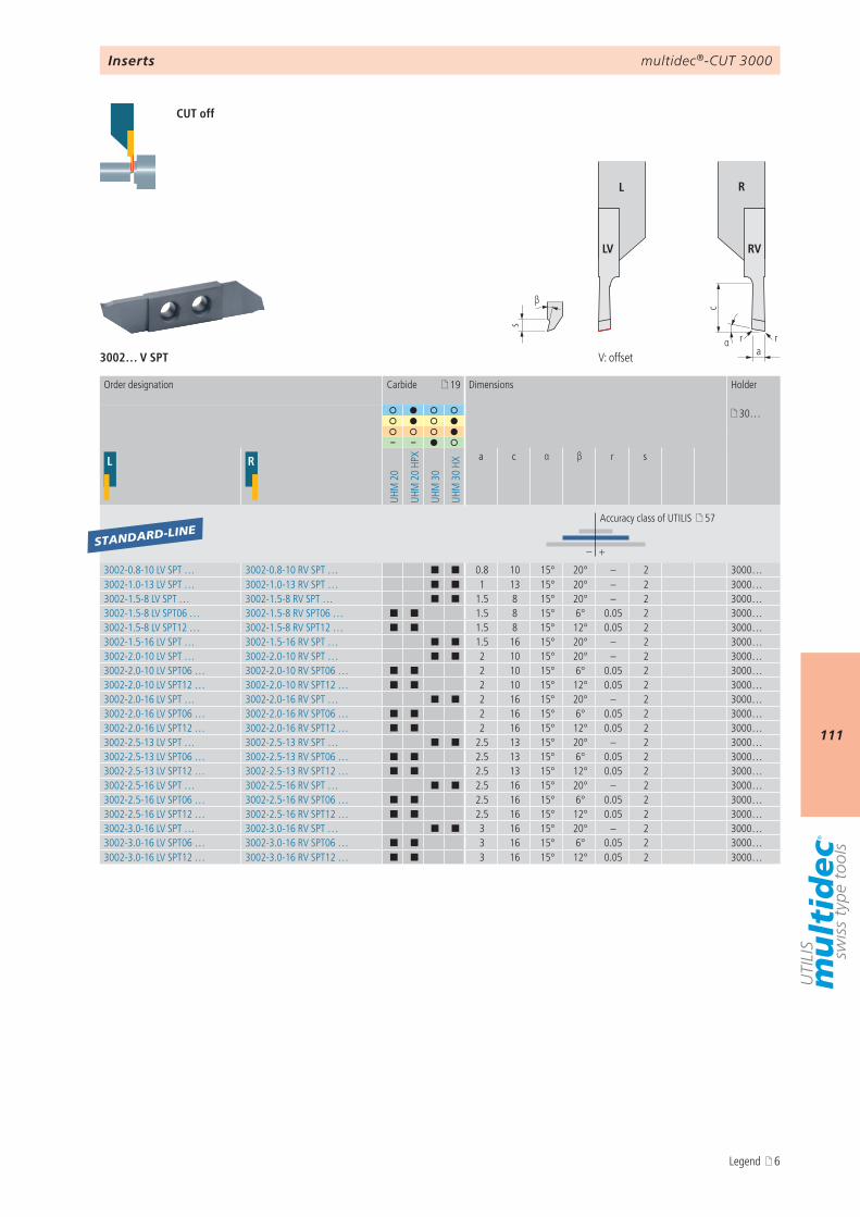
multidec®-CUT 3000
111
αa
s
β
r
c
r
L R
LV RV
3002… V SPT
19
30…
– –
L R
UHM
20
UHM
20
HPX
UHM
30
UHM
30
HXa c α β r s
– +
3002-0.8-10 LV SPT … 3002-0.8-10 RV SPT … ¢ ¢ 0.8 10 15° 20° – 2 3000…3002-1.0-13 LV SPT … 3002-1.0-13 RV SPT … ¢ ¢ 1 13 15° 20° – 2 3000…3002-1.5-8 LV SPT … 3002-1.5-8 RV SPT … ¢ ¢ 1.5 8 15° 20° – 2 3000…3002-1.5-8 LV SPT06 … 3002-1.5-8 RV SPT06 … ¢ ¢ 1.5 8 15° 6° 0.05 2 3000…3002-1.5-8 LV SPT12 … 3002-1.5-8 RV SPT12 … ¢ ¢ 1.5 8 15° 12° 0.05 2 3000…3002-1.5-16 LV SPT … 3002-1.5-16 RV SPT … ¢ ¢ 1.5 16 15° 20° – 2 3000…3002-2.0-10 LV SPT … 3002-2.0-10 RV SPT … ¢ ¢ 2 10 15° 20° – 2 3000…3002-2.0-10 LV SPT06 … 3002-2.0-10 RV SPT06 … ¢ ¢ 2 10 15° 6° 0.05 2 3000…3002-2.0-10 LV SPT12 … 3002-2.0-10 RV SPT12 … ¢ ¢ 2 10 15° 12° 0.05 2 3000…3002-2.0-16 LV SPT … 3002-2.0-16 RV SPT … ¢ ¢ 2 16 15° 20° – 2 3000…3002-2.0-16 LV SPT06 … 3002-2.0-16 RV SPT06 … ¢ ¢ 2 16 15° 6° 0.05 2 3000…3002-2.0-16 LV SPT12 … 3002-2.0-16 RV SPT12 … ¢ ¢ 2 16 15° 12° 0.05 2 3000…3002-2.5-13 LV SPT … 3002-2.5-13 RV SPT … ¢ ¢ 2.5 13 15° 20° – 2 3000…3002-2.5-13 LV SPT06 … 3002-2.5-13 RV SPT06 … ¢ ¢ 2.5 13 15° 6° 0.05 2 3000…3002-2.5-13 LV SPT12 … 3002-2.5-13 RV SPT12 … ¢ ¢ 2.5 13 15° 12° 0.05 2 3000…3002-2.5-16 LV SPT … 3002-2.5-16 RV SPT … ¢ ¢ 2.5 16 15° 20° – 2 3000…3002-2.5-16 LV SPT06 … 3002-2.5-16 RV SPT06 … ¢ ¢ 2.5 16 15° 6° 0.05 2 3000…3002-2.5-16 LV SPT12 … 3002-2.5-16 RV SPT12 … ¢ ¢ 2.5 16 15° 12° 0.05 2 3000…3002-3.0-16 LV SPT … 3002-3.0-16 RV SPT … ¢ ¢ 3 16 15° 20° – 2 3000…3002-3.0-16 LV SPT06 … 3002-3.0-16 RV SPT06 … ¢ ¢ 3 16 15° 6° 0.05 2 3000…3002-3.0-16 LV SPT12 … 3002-3.0-16 RV SPT12 … ¢ ¢ 3 16 15° 12° 0.05 2 3000…
STANDARD-LINE
Inserts
CUT off
V: offset
Order designation Carbide Dimensions Holder
Accuracy class of UTILIS 57
Legend 6
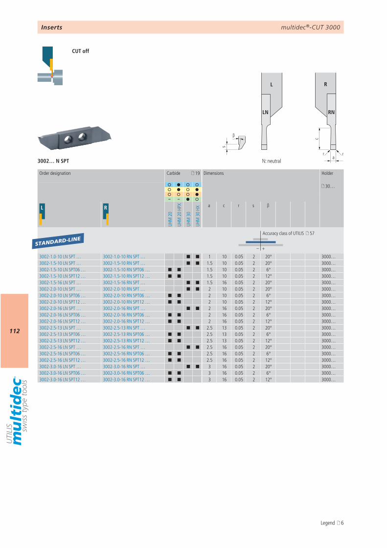
multidec®-CUT 3000
112
c
a
s
β
rr
L R
LN RN
3002… N SPT
19
30…
– –
L R
UHM
20
UHM
20
HPX
UHM
30
UHM
30
HX
a c r s β
– +
3002-1.0-10 LN SPT … 3002-1.0-10 RN SPT … ¢ ¢ 1 10 0.05 2 20° 3000…3002-1.5-10 LN SPT … 3002-1.5-10 RN SPT … ¢ ¢ 1.5 10 0.05 2 20° 3000…3002-1.5-10 LN SPT06 … 3002-1.5-10 RN SPT06 … ¢ ¢ 1.5 10 0.05 2 6° 3000…3002-1.5-10 LN SPT12 … 3002-1.5-10 RN SPT12 … ¢ ¢ 1.5 10 0.05 2 12° 3000…3002-1.5-16 LN SPT … 3002-1.5-16 RN SPT … ¢ ¢ 1.5 16 0.05 2 20° 3000…3002-2.0-10 LN SPT … 3002-2.0-10 RN SPT … ¢ ¢ 2 10 0.05 2 20° 3000…3002-2.0-10 LN SPT06 … 3002-2.0-10 RN SPT06 … ¢ ¢ 2 10 0.05 2 6° 3000…3002-2.0-10 LN SPT12 … 3002-2.0-10 RN SPT12 … ¢ ¢ 2 10 0.05 2 12° 3000…3002-2.0-16 LN SPT … 3002-2.0-16 RN SPT … ¢ ¢ 2 16 0.05 2 20° 3000…3002-2.0-16 LN SPT06 … 3002-2.0-16 RN SPT06 … ¢ ¢ 2 16 0.05 2 6° 3000…3002-2.0-16 LN SPT12 … 3002-2.0-16 RN SPT12 … ¢ ¢ 2 16 0.05 2 12° 3000…3002-2.5-13 LN SPT … 3002-2.5-13 RN SPT … ¢ ¢ 2.5 13 0.05 2 20° 3000…3002-2.5-13 LN SPT06 … 3002-2.5-13 RN SPT06 … ¢ ¢ 2.5 13 0.05 2 6° 3000…3002-2.5-13 LN SPT12 … 3002-2.5-13 RN SPT12 … ¢ ¢ 2.5 13 0.05 2 12° 3000…3002-2.5-16 LN SPT … 3002-2.5-16 RN SPT … ¢ ¢ 2.5 16 0.05 2 20° 3000…3002-2.5-16 LN SPT06 … 3002-2.5-16 RN SPT06 … ¢ ¢ 2.5 16 0.05 2 6° 3000…3002-2.5-16 LN SPT12 … 3002-2.5-16 RN SPT12 … ¢ ¢ 2.5 16 0.05 2 12° 3000…3002-3.0-16 LN SPT … 3002-3.0-16 RN SPT … ¢ ¢ 3 16 0.05 2 20° 3000…3002-3.0-16 LN SPT06 … 3002-3.0-16 RN SPT06 … ¢ ¢ 3 16 0.05 2 6° 3000…3002-3.0-16 LN SPT12 … 3002-3.0-16 RN SPT12 … ¢ ¢ 3 16 0.05 2 12° 3000…
STANDARD-LINE
Inserts
CUT off
Order designation Carbide Dimensions Holder
Accuracy class of UTILIS 57
N: neutral
Legend 6

multidec®-CUT 3000
113
AttentionPlease note the legend 6…
Notes
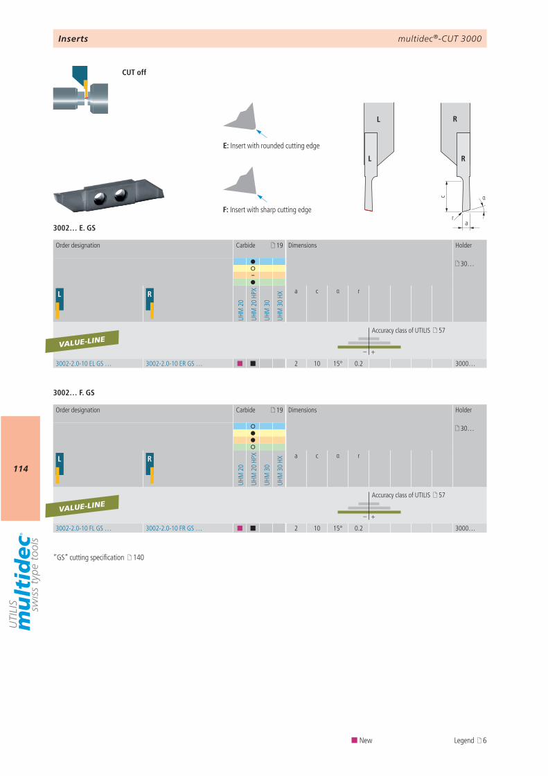
multidec®-CUT 3000
114
3002… F. GS
3002… E. GS
E F
E Fαc
ar
L R
L R
19
30…
–
L R
UHM
20
UHM
20
HPX
UHM
30
UHM
30
HX
a c α r
– +
3002-2.0-10 EL GS … 3002-2.0-10 ER GS … ¢ ¢ 2 10 15° 0.2 3000…
VALUE-LINE
19
30…
L R
UHM
20
UHM
20
HPX
UHM
30
UHM
30
HX
a c α r
– +
3002-2.0-10 FL GS … 3002-2.0-10 FR GS … ¢ ¢ 2 10 15° 0.2 3000…
VALUE-LINE
Inserts
CUT off
Order designation Carbide Dimensions Holder
Accuracy class of UTILIS 57
Order designation Carbide Dimensions Holder
Accuracy class of UTILIS 57
“GS” cutting specification 140
E: Insert with rounded cutting edge
F: Insert with sharp cutting edge
¢ New Legend 6
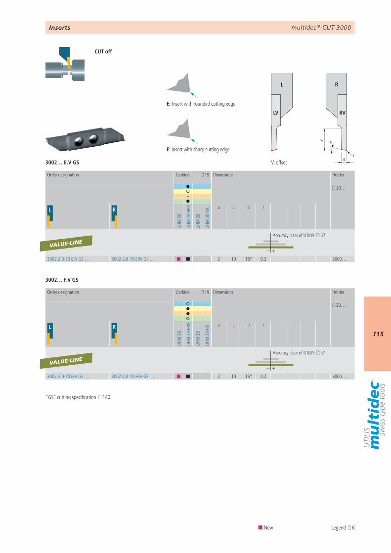
multidec®-CUT 3000
115
3002… E.V GS
3002… F.V GS
19
30…
–
L R
UHM
20
UHM
20
HPX
UHM
30
UHM
30
HXa c α r
– +
3002-2.0-10 ELV GS … 3002-2.0-10 ERV GS … ¢ ¢ 2 10 15° 0.2 3000…
VALUE-LINE
19
30…
L R
UHM
20
UHM
20
HPX
UHM
30
UHM
30
HX
a c α r
– +
3002-2.0-10 FLV GS … 3002-2.0-10 FRV GS … ¢ ¢ 2 10 15° 0.2 3000…
VALUE-LINE
E F
E F
r
αc
a
L R
LV RV
Inserts
CUT off
Order designation Carbide Dimensions Holder
Accuracy class of UTILIS 57
Order designation Carbide Dimensions Holder
Accuracy class of UTILIS 57
V: offset
“GS” cutting specification 140
E: Insert with rounded cutting edge
F: Insert with sharp cutting edge
¢ New Legend 6
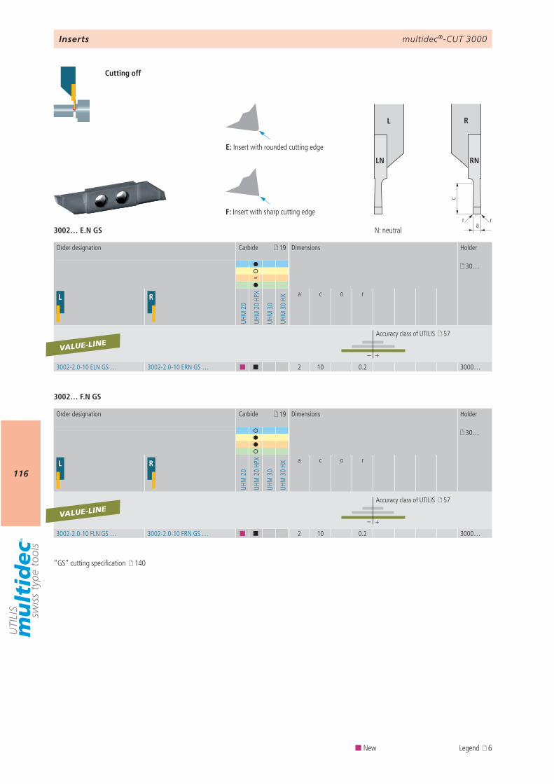
multidec®-CUT 3000
116
3002… E.N GS
3002… F.N GS
c
a
s
β
rr
L R
LN RN
19
30…
–
L R
UHM
20
UHM
20
HPX
UHM
30
UHM
30
HX
a c α r
– +
3002-2.0-10 ELN GS … 3002-2.0-10 ERN GS … ¢ ¢ 2 10 0.2 3000…
VALUE-LINE
19
30…
L R
UHM
20
UHM
20
HPX
UHM
30
UHM
30
HX
a c α r
– +
3002-2.0-10 FLN GS … 3002-2.0-10 FRN GS … ¢ ¢ 2 10 0.2 3000…
VALUE-LINE
E F
E F
Inserts
Cutting off
Order designation Carbide Dimensions Holder
Accuracy class of UTILIS 57
Order designation Carbide Dimensions Holder
Accuracy class of UTILIS 57
E: Insert with rounded cutting edge
F: Insert with sharp cutting edge
N: neutral
“GS” cutting specification 140
¢ New Legend 6
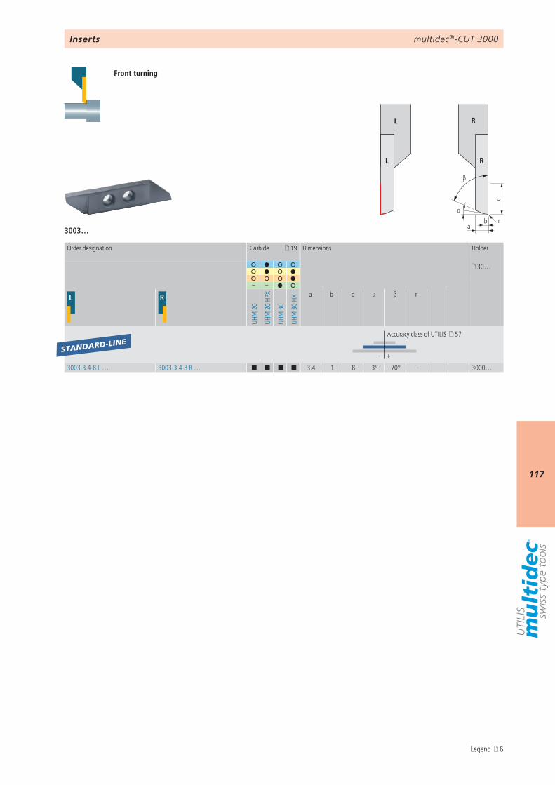
multidec®-CUT 3000
117
α
c
ab
β
r
L R
L R
3003…
19
30…
– –
L R
UHM
20
UHM
20
HPX
UHM
30
UHM
30
HXa b c α β r
– +
3003-3.4-8 L … 3003-3.4-8 R … ¢ ¢ ¢ ¢ 3.4 1 8 3° 70° – 3000…
STANDARD-LINE
Inserts
Front turning
Order designation Carbide Dimensions Holder
Accuracy class of UTILIS 57
Legend 6
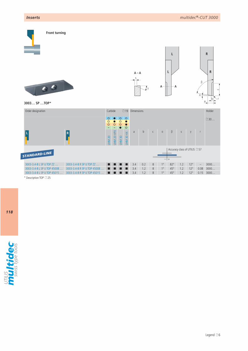
multidec®-CUT 3000
118
α
c
ab
β
γ
s
A – A
AA
r
L R
L R
3003… SP …TOP*
19
30…
– –
L R
UHM
20
UHM
20
HPX
UHM
30
UHM
30
HX
a b c α β s γ r
– +
3003-3.4-8 L SP U TOP ZZ … 3003-3.4-8 R SP U TOP ZZ … ¢ ¢ ¢ ¢ 3.4 0.2 8 1° 82° 1.2 12° – 3000…3003-3.4-8 L SP U TOP 45008 … 3003-3.4-8 R SP U TOP 45008 … ¢ ¢ ¢ ¢ 3.4 1.2 8 1° 45° 1.2 12° 0.08 3000…3003-3.4-8 L SP U TOP 45015 … 3003-3.4-8 R SP U TOP 45015 … ¢ ¢ ¢ ¢ 3.4 1.2 8 1° 45° 1.2 12° 0.15 3000…
STANDARD-LINE
Inserts
Front turning
Order designation Carbide Dimensions Holder
Accuracy class of UTILIS 57
* Description TOP 25
Legend 6
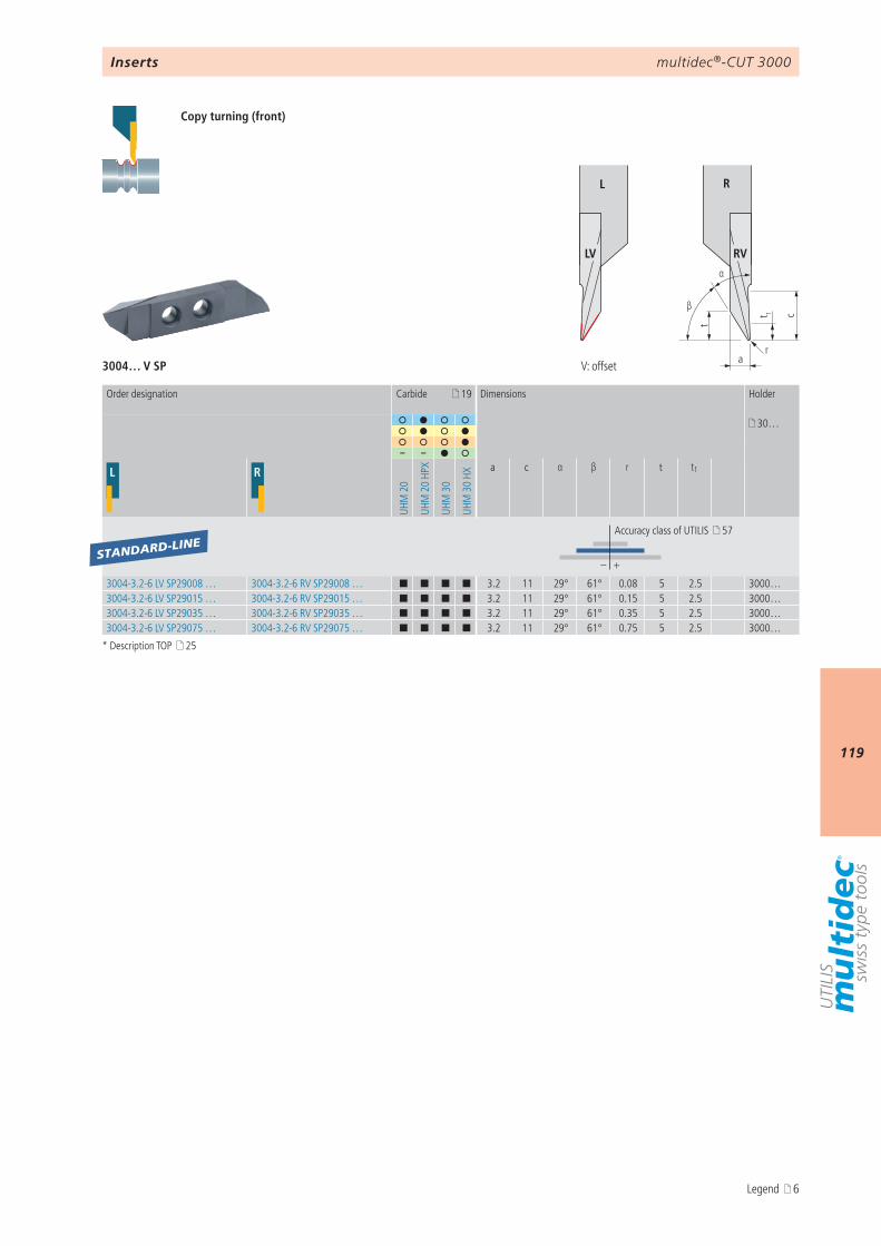
multidec®-CUT 3000
119
t
a
β
α
r
ct 1
L R
LV RV
3004… V SP
19
30…
– –
L R
UHM
20
UHM
20
HPX
UHM
30
UHM
30
HXa c α β r t t1
– +
3004-3.2-6 LV SP29008 … 3004-3.2-6 RV SP29008 … ¢ ¢ ¢ ¢ 3.2 11 29° 61° 0.08 5 2.5 3000…3004-3.2-6 LV SP29015 … 3004-3.2-6 RV SP29015 … ¢ ¢ ¢ ¢ 3.2 11 29° 61° 0.15 5 2.5 3000…3004-3.2-6 LV SP29035 … 3004-3.2-6 RV SP29035 … ¢ ¢ ¢ ¢ 3.2 11 29° 61° 0.35 5 2.5 3000…3004-3.2-6 LV SP29075 … 3004-3.2-6 RV SP29075 … ¢ ¢ ¢ ¢ 3.2 11 29° 61° 0.75 5 2.5 3000…
STANDARD-LINE
Inserts
Copy turning (front)
Order designation Carbide Dimensions Holder
Accuracy class of UTILIS 57
V: offset
* Description TOP 25
Legend 6
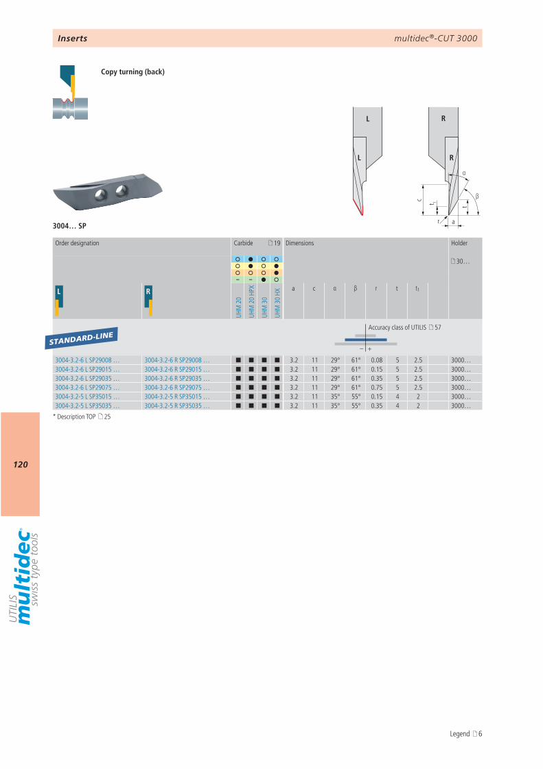
multidec®-CUT 3000
120t
a
β
α
t 1
r
c
L R
L R
3004… SP
19
30…
– –
L R
UHM
20
UHM
20
HPX
UHM
30
UHM
30
HX
a c α β r t t1
– +
3004-3.2-6 L SP29008 … 3004-3.2-6 R SP29008 … ¢ ¢ ¢ ¢ 3.2 11 29° 61° 0.08 5 2.5 3000…3004-3.2-6 L SP29015 … 3004-3.2-6 R SP29015 … ¢ ¢ ¢ ¢ 3.2 11 29° 61° 0.15 5 2.5 3000…3004-3.2-6 L SP29035 … 3004-3.2-6 R SP29035 … ¢ ¢ ¢ ¢ 3.2 11 29° 61° 0.35 5 2.5 3000…3004-3.2-6 L SP29075 … 3004-3.2-6 R SP29075 … ¢ ¢ ¢ ¢ 3.2 11 29° 61° 0.75 5 2.5 3000…3004-3.2-5 L SP35015 … 3004-3.2-5 R SP35015 … ¢ ¢ ¢ ¢ 3.2 11 35° 55° 0.15 4 2 3000…3004-3.2-5 L SP35035 … 3004-3.2-5 R SP35035 … ¢ ¢ ¢ ¢ 3.2 11 35° 55° 0.35 4 2 3000…
STANDARD-LINE
Inserts
Copy turning (back)
Order designation Carbide Dimensions Holder
Accuracy class of UTILIS 57
* Description TOP 25
Legend 6

multidec®-CUT 3000
1213
ab
β
c
d
γr δ
L R
L R
3004… TOP*
19
30…
– –
L R
UHM
20
UHM
20
HPX
UHM
30
UHM
30
HXa b c d β γ r δ
– +
3004-0.8-6 L TOP ZZ … 3004-0.8-6 R TOP ZZ … ¢ ¢ ¢ ¢ 0.8 0.5 6 2 70° 8° – 1° 3000…3004-1.0-6 L TOP ZZ … 3004-1.0-6 R TOP ZZ … ¢ ¢ ¢ ¢ 1 0.5 6 2.2 70° 8° – 1° 3000…3004-1.2-8 L TOP ZZ … 3004-1.2-8 R TOP ZZ … ¢ ¢ ¢ ¢ 1.2 0.5 8 2.4 70° 8° – 1° 3000…3004-1.5-8 L TOP ZZ … 3004-1.5-8 R TOP ZZ … ¢ ¢ ¢ ¢ 1.5 0.5 8 2.7 70° 8° – 1° 3000…3004-1.8-8 L TOP ZZ … 3004-1.8-8 R TOP ZZ … ¢ ¢ ¢ ¢ 1.8 0.5 8 3 70° 8° – 1° 3000…
STANDARD-LINE
Inserts
Back turning
Order designation Carbide Dimensions Holder
Accuracy class of UTILIS 57
* Description TOP 25
Legend 6
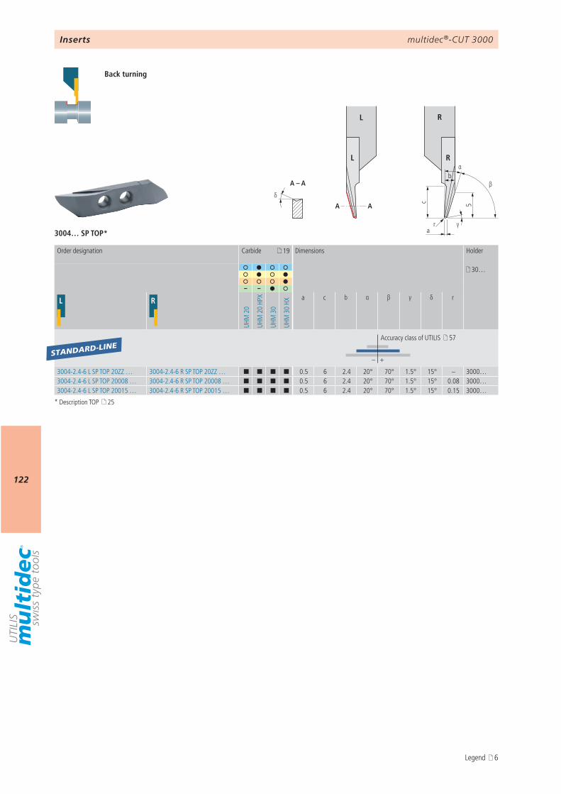
multidec®-CUT 3000
122
a
c
γ
β
α
5
b
r
A – A
AAδ
L R
L R
3004… SP TOP*
19
30…
– –
L R
UHM
20
UHM
20
HPX
UHM
30
UHM
30
HX
a c b α β γ δ r
– +
3004-2.4-6 L SP TOP 20ZZ … 3004-2.4-6 R SP TOP 20ZZ … ¢ ¢ ¢ ¢ 0.5 6 2.4 20° 70° 1.5° 15° – 3000…3004-2.4-6 L SP TOP 20008 … 3004-2.4-6 R SP TOP 20008 … ¢ ¢ ¢ ¢ 0.5 6 2.4 20° 70° 1.5° 15° 0.08 3000…3004-2.4-6 L SP TOP 20015 … 3004-2.4-6 R SP TOP 20015 … ¢ ¢ ¢ ¢ 0.5 6 2.4 20° 70° 1.5° 15° 0.15 3000…
STANDARD-LINE
Inserts
Back turning
Order designation Carbide Dimensions Holder
Accuracy class of UTILIS 57
* Description TOP 25
Legend 6
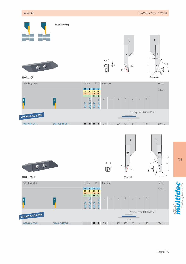
multidec®-CUT 3000
123
δ
A – A
AA 4.
2
a
β
α
c
γr
L R
L R
A – A
δA
A 4
a
β
α
c
γ r
L R
LV RV
3004… CP
3004… V CP
19
30…
– –
L R
UHM
20
UHM
20
HPX
UHM
30
UHM
30
HX
a c α β γ r δ
– +
3004-0.8-4 LV CP … 3004-0.8-4 RV CP … ¢ ¢ 0.8 11 20° 70° 2° – 8° 3000…
19
30…
– –
L R
UHM
20
UHM
20
HPX
UHM
30
UHM
30
HXa c α β γ r δ
– +
3004-0.8-4 L CP … 3004-0.8-4 R CP … ¢ ¢ ¢ ¢ 0.8 11 20° 70° 2° – 8° 3000…
STANDARD-LINE
STANDARD-LINE
Inserts
Back turning
V: offset
Order designation Carbide Dimensions Holder
Accuracy class of UTILIS 57
Order designation Carbide Dimensions Holder
Accuracy class of UTILIS 57
Legend 6
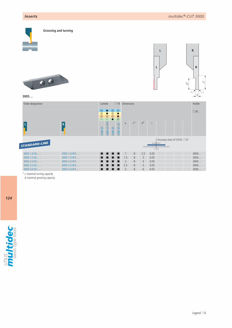
multidec®-CUT 3000
124
d* c*
arr
L R
L R
3005…
19
30…
– –
L R
UHM
20
UHM
20
HPX
UHM
30
UHM
30
HX
a c* d* r
– +
3005-1.0-8 L … 3005-1.0-8 R … ¢ ¢ ¢ ¢ 1 8 2.5 0.05 3000…3005-1.5-8 L … 3005-1.5-8 R … ¢ ¢ ¢ ¢ 1.5 8 3 0.05 3000…3005-2.0-8 L … 3005-2.0-8 R … ¢ ¢ ¢ ¢ 2 8 4 0.05 3000…3005-2.5-8 L … 3005-2.5-8 R … ¢ ¢ ¢ ¢ 2.5 8 5 0.05 3000…3005-3.0-8 L … 3005-3.0-8 R … ¢ ¢ ¢ ¢ 3 8 6 0.05 3000…
STANDARD-LINE
Inserts
Grooving and turning
* c: maximal turning capacity d: maximal grooving capacity
Order designation Carbide Dimensions Holder
Accuracy class of UTILIS 57
Legend 6
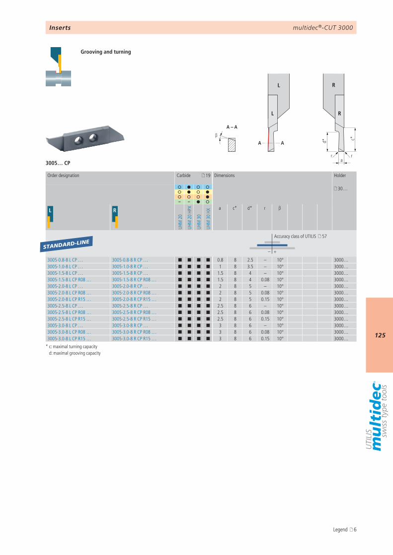
multidec®-CUT 3000
125
d* c*
arr
β
A – A
AA
L R
L R
3005… CP
19
30…
– –
L R
UHM
20
UHM
20
HPX
UHM
30
UHM
30
HXa c* d* r β
– +
3005-0.8-8 L CP … 3005-0.8-8 R CP … ¢ ¢ ¢ ¢ 0.8 8 2.5 – 10° 3000…3005-1.0-8 L CP … 3005-1.0-8 R CP … ¢ ¢ ¢ ¢ 1 8 3.5 – 10° 3000…3005-1.5-8 L CP … 3005-1.5-8 R CP … ¢ ¢ ¢ ¢ 1.5 8 4 – 10° 3000…3005-1.5-8 L CP R08 … 3005-1.5-8 R CP R08 … ¢ ¢ ¢ ¢ 1.5 8 4 0.08 10° 3000…3005-2.0-8 L CP … 3005-2.0-8 R CP … ¢ ¢ ¢ ¢ 2 8 5 – 10° 3000…3005-2.0-8 L CP R08 … 3005-2.0-8 R CP R08 … ¢ ¢ ¢ ¢ 2 8 5 0.08 10° 3000…3005-2.0-8 L CP R15 … 3005-2.0-8 R CP R15 … ¢ ¢ ¢ ¢ 2 8 5 0.15 10° 3000…3005-2.5-8 L CP … 3005-2.5-8 R CP … ¢ ¢ ¢ ¢ 2.5 8 6 – 10° 3000…3005-2.5-8 L CP R08 … 3005-2.5-8 R CP R08 … ¢ ¢ ¢ ¢ 2.5 8 6 0.08 10° 3000…3005-2.5-8 L CP R15 … 3005-2.5-8 R CP R15 … ¢ ¢ ¢ ¢ 2.5 8 6 0.15 10° 3000…3005-3.0-8 L CP … 3005-3.0-8 R CP … ¢ ¢ ¢ ¢ 3 8 6 – 10° 3000…3005-3.0-8 L CP R08 … 3005-3.0-8 R CP R08 … ¢ ¢ ¢ ¢ 3 8 6 0.08 10° 3000…3005-3.0-8 L CP R15 … 3005-3.0-8 R CP R15 … ¢ ¢ ¢ ¢ 3 8 6 0.15 10° 3000…
STANDARD-LINE
Inserts
Grooving and turning
* c: maximal turning capacity d: maximal grooving capacity
Order designation Carbide Dimensions Holder
Accuracy class of UTILIS 57
Legend 6
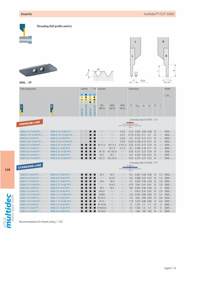
multidec®-CUT 3000
126
c
a1P
b
a2
h min
60°
L R
L R
3006… VP
19
30…
– –
L R
UHM
20
UHM
20
HPX
UHM
30
UHM
30
HX
ISO DIN13
NIHS 06-03
NIHS 06-02
P hmin a1 a2 b c
– +
3006-0.15-10-60 VP L … 3006-0.15-10-60 VP R … ¢ ¢ – – S 0.6 0.15 0.092 0.09 0.08 8 – 3000…3006-0.175-10-60 VP L … 3006-0.175-10-60 VP R … ¢ ¢ – – S 0.7 0.175 0.107 0.11 0.1 8 – 3000…3006-0.2-10-60 VP L … 3006-0.2-10-60 VP R … ¢ ¢ – – S 0.8 0.2 0.123 0.12 0.11 8 – 3000…3006-0.225-10-60 VP L … 3006-0.225-10-60 VP R … ¢ ¢ – – S 0.9 0.225 0.138 0.14 0.12 8 – 3000…3006-0.25-10-60 VP L … 3006-0.25-10-60 VP R … ¢ ¢ ¢ ¢ M 1/1.2 M 1/1.2 S 1/S1.2 0.25 0.153 0.15 0.14 8 – 3000…3006-0.3-10-60 VP L … 3006-0.3-10-60 VP R … ¢ ¢ ¢ ¢ – M 1.4 S 1.4 0.3 0.184 0.18 0.17 8 – 3000…3006-0.35-10-60 VP L … 3006-0.35-10-60 VP R … ¢ ¢ ¢ ¢ M 1.6 M 1.6/1.8 – 0.35 0.215 0.21 0.19 8 – 3000…3006-0.4-10-60 VP L … 3006-0.4-10-60 VP R … ¢ ¢ ¢ ¢ M 2 M 2 – 0.4 0.245 0.24 0.22 8 – 3000…3006-0.45-10-60 VP L … 3006-0.45-10-60 VP R … ¢ ¢ ¢ ¢ M 2.5 M 2.2/2.5 – 0.45 0.276 0.27 0.25 8 – 3000…
– +
3006-0.5-10-60 VP L … 3006-0.5-10-60 VP R … ¢ ¢ ¢ ¢ M 3 M 3 – 0.5 0.307 0.28 0.28 8 1.3 3000…3006-0.6-10-60 VP L … 3006-0.6-10-60 VP R … ¢ ¢ ¢ ¢ – M 3.5 – 0.6 0.368 0.33 0.33 8 1.5 3000…3006-0.7-10-60 VP L … 3006-0.7-10-60 VP R … ¢ ¢ ¢ ¢ M 4 M 4 – 0.7 0.429 0.39 0.39 8 1.8 3000…3006-0.75-10-60 VP L … 3006-0.75-10-60 VP R … ¢ ¢ ¢ ¢ – M 4.5 – 0.75 0.46 0.41 0.41 8 1.9 3000…3006-0.8-10-60 VP L … 3006-0.8-10-60 VP R … ¢ ¢ ¢ ¢ M 5 M 5 – 0.8 0.491 0.44 0.44 8 2 3000…3006-1.0-10-60 VP L … 3006-1.0-10-60 VP R … ¢ ¢ ¢ ¢ M 6/7 – – 1 0.613 0.55 0.55 8 2.5 3000…3006-1.25-10-60 VP L … 3006-1.25-10-60 VP R … ¢ ¢ ¢ ¢ M 8/9 – – 1.25 0.767 0.69 0.69 8 3.1 3000…3006-1.5-10-60 VP L … 3006-1.5-10-60 VP R … ¢ ¢ ¢ ¢ M 10/11 – – 1.5 0.92 0.83 0.83 8 3.8 3000…3006-1.75-10-60 VP L … 3006-1.75-10-60 VP R … ¢ ¢ ¢ ¢ M 12 – – 1.75 1.073 0.96 0.96 8 4.4 3000…3006-2.0-10-60 VP L … 3006-2.0-10-60 VP R … ¢ ¢ ¢ ¢ M 14/16 – – 2 1.227 1.1 1.1 8 5 3000…3006-2.5-10-60 VP L … 3006-2.5-10-60 VP R … ¢ ¢ ¢ ¢ M 18/20/22 – – 2.5 1.534 1.4 1.4 8 5 3000…3006-3.0-10-60 VP L … 3006-3.0-10-60 VP R … ¢ ¢ ¢ ¢ M 24/27 – – 3 1.84 1.65 1.65 8 5 3000…
PREMIUM-LINE
STANDARD-LINE
Inserts
Pitch
Order designation Carbide Standard Dimensions Holder
Accuracy class of UTILIS 57
Accuracy class of UTILIS 57
Threading (full profile metric)
Recommendations for thread cutting 142
Legend 6
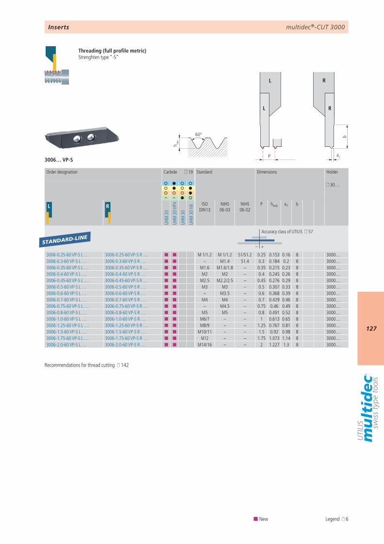
multidec®-CUT 3000
127
3006… VP-S
19
30…
– –
L R
UHM
20
UHM
20
HPX
UHM
30
UHM
30
HX
ISO DIN13
NIHS 06-03
NIHS 06-02
P hmin a1 b
– +
3006-0.25-60 VP-S L … 3006-0.25-60 VP-S R … ¢ ¢ M 1/1.2 M 1/1.2 S1/S1.2 0.25 0.153 0.16 8 3000…3006-0.3-60 VP-S L … 3006-0.3-60 VP-S R … ¢ ¢ – M1.4 S1.4 0.3 0.184 0.2 8 3000…3006-0.35-60 VP-S L … 3006-0.35-60 VP-S R … ¢ ¢ M1.6 M1.6/1.8 – 0.35 0.215 0.23 8 3000…3006-0.4-60 VP-S L … 3006-0.4-60 VP-S R … ¢ ¢ M2 M2 – 0.4 0.245 0.26 8 3000…3006-0.45-60 VP-S L … 3006-0.45-60 VP-S R … ¢ ¢ M2.5 M2.2/2.5 – 0.45 0.276 0.29 8 3000…3006-0.5-60 VP-S L … 3006-0.5-60 VP-S R … ¢ ¢ M3 M3 – 0.5 0.307 0.33 8 3000…3006-0.6-60 VP-S L … 3006-0.6-60 VP-S R … ¢ ¢ – M3.5 – 0.6 0.368 0.39 8 3000…3006-0.7-60 VP-S L … 3006-0.7-60 VP-S R … ¢ ¢ M4 M4 – 0.7 0.429 0.46 8 3000…3006-0.75-60 VP-S L … 3006-0.75-60 VP-S R … ¢ ¢ – M4.5 – 0.75 0.46 0.49 8 3000…3006-0.8-60 VP-S L … 3006-0.8-60 VP-S R … ¢ ¢ M5 M5 – 0.8 0.491 0.52 8 3000…3006-1.0-60 VP-S L … 3006-1.0-60 VP-S R … ¢ ¢ M6/7 – – 1 0.613 0.65 8 3000…3006-1.25-60 VP-S L … 3006-1.25-60 VP-S R … ¢ ¢ M8/9 – – 1.25 0.767 0.81 8 3000…3006-1.5-60 VP-S L … 3006-1.5-60 VP-S R … ¢ ¢ M10/11 – – 1.5 0.92 0.98 8 3000…3006-1.75-60 VP-S L … 3006-1.75-60 VP-S R … ¢ ¢ M12 – – 1.75 1.073 1.14 8 3000…3006-2.0-60 VP-S L … 3006-2.0-60 VP-S R … ¢ ¢ M14/16 – – 2 1.227 1.3 8 3000…
STANDARD-LINE
P
b
a1
h min
60°
L R
L R
Inserts
Order designation Carbide Standard Dimensions Holder
Accuracy class of UTILIS 57
Threading (full profile metric)Strenghten type “-S”
Recommendations for thread cutting 142
¢ New Legend 6
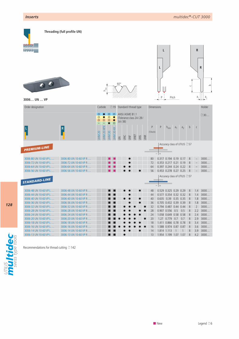
multidec®-CUT 3000
128
3006… UN … VP
19
30…
– –
L R
UHM
20
UHM
20
HPX
UHM
30
UHM
30
HX
UN UNC
UNF
UNEF
UNS
UNR
P P hmin a1 a2 b c
– +
3006-80 UN 10-60 VP L … 3006-80 UN 10-60 VP R … ¢ ¢ 80 0.317 0.194 0.19 0.17 8 – 3000…3006-72 UN 10-60 VP L … 3006-72 UN 10-60 VP R … ¢ ¢ 72 0.353 0.217 0.21 0.19 8 – 3000…3006-64 UN 10-60 VP L … 3006-64 UN 10-60 VP R … ¢ ¢ 64 0.397 0.244 0.24 0.22 8 – 3000…3006-56 UN 10-60 VP L … 3006-56 UN 10-60 VP R … ¢ ¢ 56 0.453 0.278 0.27 0.25 8 – 3000…
– +
3006-48 UN 10-60 VP L … 3006-48 UN 10-60 VP R … ¢ ¢ 48 0.529 0.325 0.29 0.29 8 1.4 3000…3006-44 UN 10-60 VP L … 3006-44 UN 10-60 VP R … ¢ ¢ 44 0.577 0.354 0.32 0.32 8 1.4 3000…3006-40 UN 10-60 VP L … 3006-40 UN 10-60 VP R … ¢ ¢ 40 0.635 0.39 0.35 0.35 8 1.8 3000…3006-36 UN 10-60 VP L … 3006-36 UN 10-60 VP R … ¢ ¢ 36 0.705 0.432 0.39 0.39 8 1.8 3000…3006-32 UN 10-60 VP L … 3006-32 UN 10-60 VP R … ¢ ¢ 32 0.794 0.487 0.44 0.44 8 2 3000…3006-28 UN 10-60 VP L … 3006-28 UN 10-60 VP R … ¢ ¢ 28 0.907 0.556 0.5 0.5 8 2.2 3000…3006-24 UN 10-60 VP L … 3006-24 UN 10-60 VP R … ¢ ¢ 24 1.058 0.649 0.58 0.58 8 2.4 3000…3006-20 UN 10-60 VP L … 3006-20 UN 10-60 VP R … ¢ ¢ 20 1.27 0.779 0.7 0.7 8 2.9 3000…3006-18 UN 10-60 VP L … 3006-18 UN 10-60 VP R … ¢ ¢ 18 1.411 0.866 0.78 0.78 8 3.4 3000…3006-16 UN 10-60 VP L … 3006-16 UN 10-60 VP R … ¢ ¢ 16 1.588 0.974 0.87 0.87 8 3.6 3000…3006-14 UN 10-60 VP L … 3006-14 UN 10-60 VP R … ¢ ¢ 14 1.814 1.113 1 1 8 3.9 3000…3006-13 UN 10-60 VP L … 3006-13 UN 10-60 VP R … ¢ ¢ 13 1.954 1.199 1.07 1.07 8 4.2 3000…
PREMIUM-LINE
STANDARD-LINE
c
a1P
b
a2
h min
60°
L R
L R
Inserts
Pitch
Threading (full profile UN)
Order designation Carbide Standard / thread type
ANSI / ASME B1.1(Tolerance class 2A / 2B / 3A / 3B)
Dimensions Holder
(T/Inch)
Accuracy class of UTILIS 57
Accuracy class of UTILIS 57
Recommendations for thread cutting 142
¢ New Legend 6
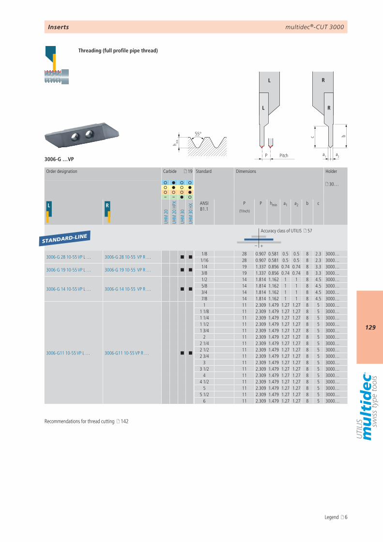
multidec®-CUT 3000
129
3006-G …VP
c
a1P
b
a2
h min
55°
L R
L R
19
30…
– –
L R
UHM
20
UHM
20
HPX
UHM
30
UHM
30
HX
ANSI B1.1
P P hmin a1 a2 b c
– +
3006-G 28 10-55 VP L … 3006-G 28 10-55 VP R … ¢ ¢1/8 28 0.907 0.581 0.5 0.5 8 2.3 3000…1/16 28 0.907 0.581 0.5 0.5 8 2.3 3000…
3006-G 19 10-55 VP L … 3006-G 19 10-55 VP R … ¢ ¢1/4 19 1.337 0.856 0.74 0.74 8 3.3 3000…3/8 19 1.337 0.856 0.74 0.74 8 3.3 3000…
3006-G 14 10-55 VP L … 3006-G 14 10-55 VP R … ¢ ¢
1/2 14 1.814 1.162 1 1 8 4.5 3000…5/8 14 1.814 1.162 1 1 8 4.5 3000…3/4 14 1.814 1.162 1 1 8 4.5 3000…7/8 14 1.814 1.162 1 1 8 4.5 3000…
3006-G11 10-55 VP L … 3006-G11 10-55 VP R … ¢ ¢
1 11 2.309 1.479 1.27 1.27 8 5 3000…1 1/8 11 2.309 1.479 1.27 1.27 8 5 3000…1 1/4 11 2.309 1.479 1.27 1.27 8 5 3000…1 1/2 11 2.309 1.479 1.27 1.27 8 5 3000…1 3/4 11 2.309 1.479 1.27 1.27 8 5 3000…
2 11 2.309 1.479 1.27 1.27 8 5 3000…2 1/4 11 2.309 1.479 1.27 1.27 8 5 3000…2 1/2 11 2.309 1.479 1.27 1.27 8 5 3000…2 3/4 11 2.309 1.479 1.27 1.27 8 5 3000…
3 11 2.309 1.479 1.27 1.27 8 5 3000…3 1/2 11 2.309 1.479 1.27 1.27 8 5 3000…
4 11 2.309 1.479 1.27 1.27 8 5 3000…4 1/2 11 2.309 1.479 1.27 1.27 8 5 3000…
5 11 2.309 1.479 1.27 1.27 8 5 3000…5 1/2 11 2.309 1.479 1.27 1.27 8 5 3000…
6 11 2.309 1.479 1.27 1.27 8 5 3000…
STANDARD-LINE
Inserts
Pitch
Threading (full profile pipe thread)
Order designation Carbide Standard Dimensions Holder
(T/Inch)
Accuracy class of UTILIS 57
Recommendations for thread cutting 142
Legend 6
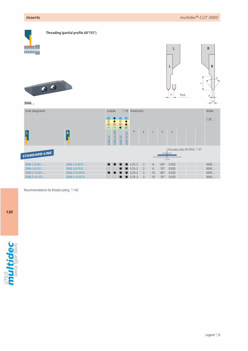
multidec®-CUT 3000
130
3006…
c
α
P e
a
L R
L R
19
30…
– –
L R
UHM
20
UHM
20
HPX
UHM
30
UHM
30
HX
P a c α e
– +
3006-2-6-60 L … 3006-2-6-60 R … ¢ ¢ ¢ ¢ 0.25–2 2 6 60° 0.035 3000…3006-2-6-55 L … 3006-2-6-55 R … ¢ ¢ 0.25–2 2 6 55° 0.035 3000…3006-3-10-60 L … 3006-3-10-60 R … ¢ ¢ ¢ ¢ 0.25–2 3 10 60° 0.035 3000…3006-3-10-55 L … 3006-3-10-55 R … ¢ ¢ 0.25–2 3 10 55° 0.035 3000…
STANDARD-LINE
Inserts
Threading (partial profile 60°/55°)
Pitch
Order designation Carbide Dimensions Holder
Accuracy class of UTILIS 57
Recommendations for thread cutting 142
Legend 6
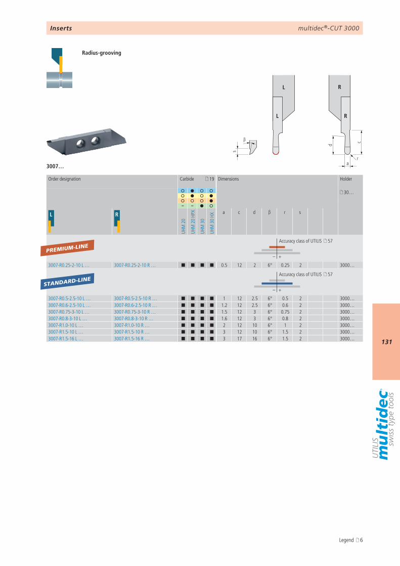
multidec®-CUT 3000
131
d c
a
s
β
r
L R
L R
3007…
19
30…
– –
L R
UHM
20
UHM
20
HPX
UHM
30
UHM
30
HXa c d β r s
– +
3007-R0.25-2-10 L … 3007-R0.25-2-10 R … ¢ ¢ ¢ ¢ 0.5 12 2 6° 0.25 2 3000…
– +
3007-R0.5-2.5-10 L … 3007-R0.5-2.5-10 R … ¢ ¢ ¢ ¢ 1 12 2.5 6° 0.5 2 3000…3007-R0.6-2.5-10 L … 3007-R0.6-2.5-10 R … ¢ ¢ ¢ ¢ 1.2 12 2.5 6° 0.6 2 3000…3007-R0.75-3-10 L … 3007-R0.75-3-10 R … ¢ ¢ ¢ ¢ 1.5 12 3 6° 0.75 2 3000…3007-R0.8-3-10 L … 3007-R0.8-3-10 R … ¢ ¢ ¢ ¢ 1.6 12 3 6° 0.8 2 3000…3007-R1.0-10 L … 3007-R1.0-10 R … ¢ ¢ ¢ ¢ 2 12 10 6° 1 2 3000…3007-R1.5-10 L … 3007-R1.5-10 R … ¢ ¢ ¢ ¢ 3 12 10 6° 1.5 2 3000…3007-R1.5-16 L … 3007-R1.5-16 R … ¢ ¢ ¢ ¢ 3 17 16 6° 1.5 2 3000…
PREMIUM-LINE
STANDARD-LINE
Inserts
Radius-grooving
Order designation Carbide Dimensions Holder
Accuracy class of UTILIS 57
Accuracy class of UTILIS 57
Legend 6
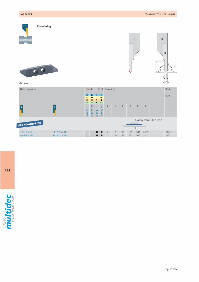
multidec®-CUT 3000
132
3012…
c
e
α
d
α
a
β
L R
L R
19
30…
– –
L R
UHM
20
UHM
20
HPX
UHM
30
UHM
30
HX
a c d α β e
– +
3012-2-6-60 L … 3012-2-6-60 R … ¢ ¢ 2 2 10 60° 60° 0.035 3000…3012-2-10-45 L … 3012-2-10-45 R … ¢ ¢ 2 10 12 45° 90° – 3000…
STANDARD-LINE
Inserts
Chamfering
Order designation Carbide Dimensions Holder
Accuracy class of UTILIS 57
Legend 6
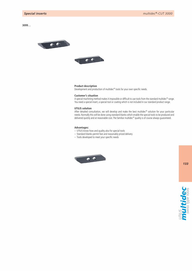
multidec®-CUT 3000
133
3099…
Special inserts
Product descriptionDevelopment and production of multidec® tools for your own specific needs.
Customer’s situationA special machining method makes it impossible or difficult to use tools from the standard multidec® range. You need a special insert, a special tool or coating which is not included in our standard product range.
UTILIS solutionAfter detailed consultation, we will develop and make the best multidec® solution for your particular needs. Normally this will be done using standard blanks which enable the special tools to be produced and delivered quickly and at reasonable cost. The familiar multidec® quality is of course always guaranteed.
Advantages:– UTILIS know-how and quality also for special tools– Standard blanks permit fast and reasonably priced delivery– Tools developed to meet your specific needs
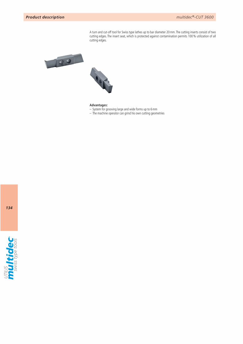
multidec®-CUT 3600
134
Product description
A turn and cut-off tool for Swiss type lathes up to bar diameter 20 mm. The cutting inserts consist of two cutting edges. The insert seat, which is protected against contamination permits 100 % utilization of all cutting edges.
Advantages:– System for grooving large and wide forms up to 6 mm– The machine operator can grind his own cutting geometries
multidec®-CUT 3600
135
9 3601… 1363605… 137 138
multidec®-CUT 3600
Technical information Inserts
3699… (special inserts)
Overview
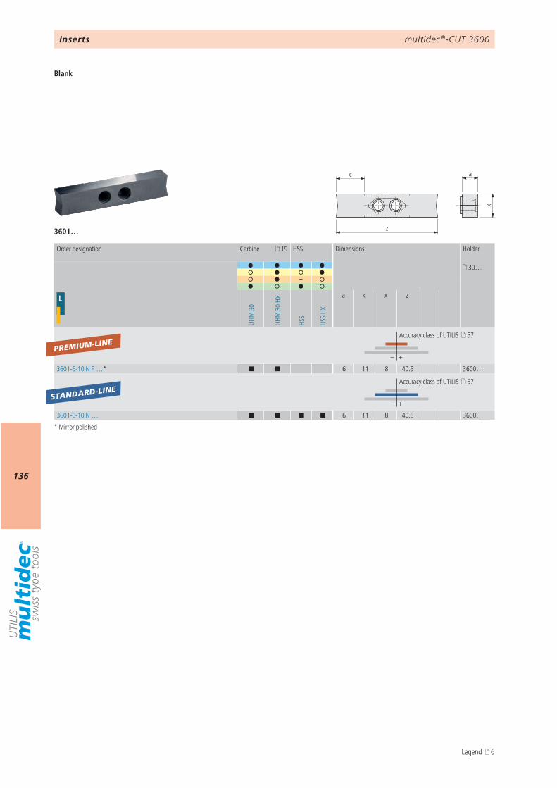
multidec®-CUT 3600
136
z
c a
x
3601…
19
30…
–
L
UHM
30
UHM
30
HX
HSS
HSS
HX
a c x z
– +
3601-6-10 N P …* ¢ ¢ 6 11 8 40.5 3600…
– +
3601-6-10 N … ¢ ¢ ¢ ¢ 6 11 8 40.5 3600…
PREMIUM-LINE
STANDARD-LINE
Inserts
Blank
* Mirror polished
Order designation Carbide HSS Dimensions Holder
Accuracy class of UTILIS 57
Accuracy class of UTILIS 57
Legend 6

multidec®-CUT 3600
137
d* c*
arr
β
A – A
AA
L R
L R
3605… CP
19
30…
L R
UHM
30
UHM
30
HXa c* d* r β
– +
3605-4.0-10 L CP … 3605-4.0-10 R CP … ¢ ¢ 4 10 10 – 10° 3600…3605-4.0-10 L CP R08 … 3605-4.0-10 R CP R08 … ¢ ¢ 4 10 10 0.08 10° 3600…3605-4.0-10 L CP R15 … 3605-4.0-10 R CP R15 … ¢ ¢ 4 10 10 0.15 10° 3600…
STANDARD-LINE
Inserts
Grooving and turning
* c: maximal turning capacity d: maximal grooving capacity
Order designation Carbide Dimensions Holder
Accuracy class of UTILIS 57
¢ New Legend 6
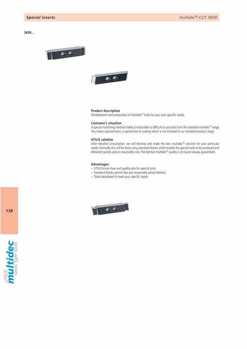
multidec®-CUT 3600
138
3699…
Special inserts
Product descriptionDevelopment and production of multidec® tools for your own specific needs.
Customer’s situationA special machining method makes it impossible or difficult to use tools from the standard multidec® range. You need a special insert, a special tool or coating which is not included in our standard product range.
UTILIS solutionAfter detailed consultation, we will develop and make the best multidec® solution for your particular needs. Normally this will be done using standard blanks which enable the special tools to be produced and delivered quickly and at reasonable cost. The familiar multidec® quality is of course always guaranteed.
Advantages:– UTILIS know-how and quality also for special tools– Standard blanks permit fast and reasonably priced delivery– Tools developed to meet your specific needs

multidec®-CUT 3600
139
AttentionPlease note the legend 6…
Notes
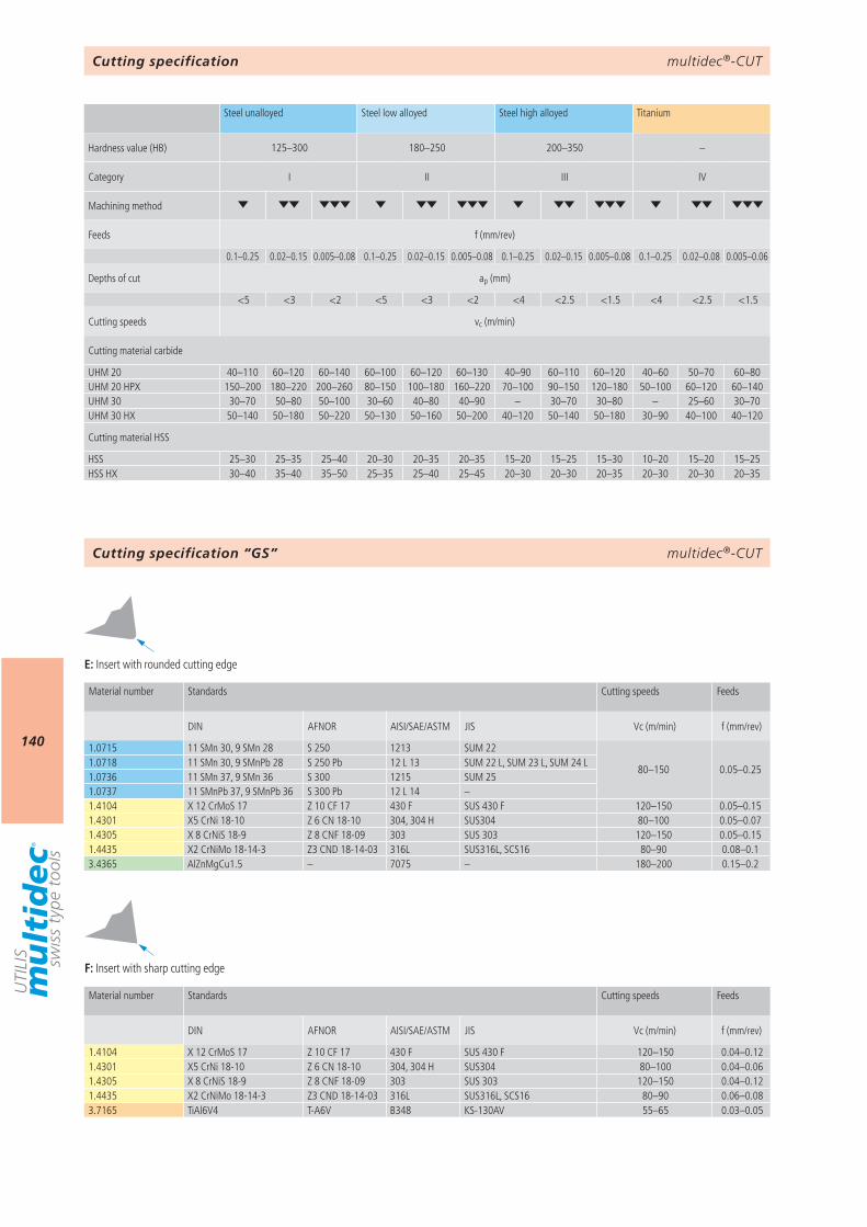
multidec®-CUT
140
125–300 180–250 200–350 –
I II III IV
0.1–0.25 0.02–0.15 0.005–0.08 0.1–0.25 0.02–0.15 0.005–0.08 0.1–0.25 0.02–0.15 0.005–0.08 0.1–0.25 0.02–0.08 0.005–0.06
ap (mm)
<5 <3 <2 <5 <3 <2 <4 <2.5 <1.5 <4 <2.5 <1.5
vc (m/min)
UHM 20 40–110 60–120 60–140 60–100 60–120 60–130 40–90 60–110 60–120 40–60 50–70 60–80UHM 20 HPX 150–200 180–220 200–260 80–150 100–180 160–220 70–100 90–150 120–180 50–100 60–120 60–140UHM 30 30–70 50–80 50–100 30–60 40–80 40–90 – 30–70 30–80 – 25–60 30–70UHM 30 HX 50–140 50–180 50–220 50–130 50–160 50–200 40–120 50–140 50–180 30–90 40–100 40–120
HSS 25–30 25–35 25–40 20–30 20–35 20–35 15–20 15–25 15–30 10–20 15–20 15–25HSS HX 30–40 35–40 35–50 25–35 25–40 25–45 20–30 20–30 20–35 20–30 20–30 20–35
E F
E F
1.0715 11 SMn 30, 9 SMn 28 S 250 1213 SUM 22
80–150 0.05–0.251.0718 11 SMn 30, 9 SMnPb 28 S 250 Pb 12 L 13 SUM 22 L, SUM 23 L, SUM 24 L1.0736 11 SMn 37, 9 SMn 36 S 300 1215 SUM 251.0737 11 SMnPb 37, 9 SMnPb 36 S 300 Pb 12 L 14 –1.4104 X 12 CrMoS 17 Z 10 CF 17 430 F SUS 430 F 120–150 0.05–0.151.4301 X5 CrNi 18-10 Z 6 CN 18-10 304, 304 H SUS304 80–100 0.05–0.071.4305 X 8 CrNiS 18-9 Z 8 CNF 18-09 303 SUS 303 120–150 0.05–0.151.4435 X2 CrNiMo 18-14-3 Z3 CND 18-14-03 316L SUS316L, SCS16 80–90 0.08–0.13.4365 AlZnMgCu1.5 – 7075 – 180–200 0.15–0.2
1.4104 X 12 CrMoS 17 Z 10 CF 17 430 F SUS 430 F 120–150 0.04–0.121.4301 X5 CrNi 18-10 Z 6 CN 18-10 304, 304 H SUS304 80–100 0.04–0.061.4305 X 8 CrNiS 18-9 Z 8 CNF 18-09 303 SUS 303 120–150 0.04–0.121.4435 X2 CrNiMo 18-14-3 Z3 CND 18-14-03 316L SUS316L, SCS16 80–90 0.06–0.083.7165 TiAl6V4 T-A6V B348 KS-130AV 55–65 0.03–0.05
multidec®-CUT
Cutting specification
Cutting specification “GS”
Steel unalloyed Steel low alloyed Steel high alloyed Titanium
Hardness value (HB)
Category
Machining method
Feeds f (mm/rev)
Depths of cut
Cutting speeds
Cutting material carbide
Cutting material HSS
E: Insert with rounded cutting edge
F: Insert with sharp cutting edge
Material number Standards Cutting speeds Feeds
DIN AFNOR AISI/SAE/ASTM JIS Vc (m/min) f (mm/rev)
Material number Standards Cutting speeds Feeds
DIN AFNOR AISI/SAE/ASTM JIS Vc (m/min) f (mm/rev)
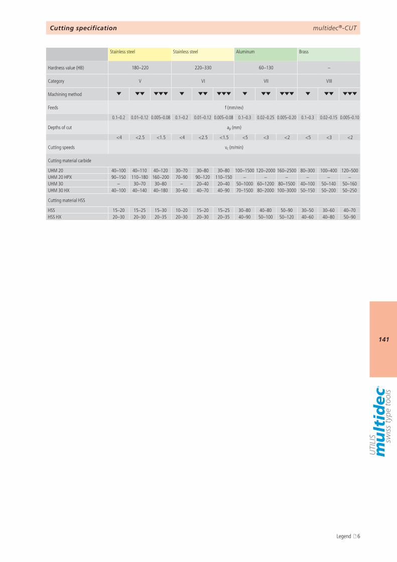
multidec®-CUT
141
180–220 220–330 60–130 –
V VI VII VIII
0.1–0.2 0.01–0.12 0.005–0.08 0.1–0.2 0.01–0.12 0.005–0.08 0.1–0.3 0.02–0.25 0.005–0.20 0.1–0.3 0.02–0.15 0.005–0.10
ap (mm)
<4 <2.5 <1.5 <4 <2.5 <1.5 <5 <3 <2 <5 <3 <2
vc (m/min)
UHM 20 40–100 40–110 40–120 30–70 30–80 30–80 100–1500 120–2000 160–2500 80–300 100–400 120–500UHM 20 HPX 90–150 110–180 160–200 70–90 90–120 110–150 – – – – – –UHM 30 – 30–70 30–80 – 20–40 20–40 50–1000 60–1200 80–1500 40–100 50–140 50–160UHM 30 HX 40–100 40–140 40–180 30–60 40–70 40–90 70–1500 80–2000 100–3000 50–150 50–200 50–250
HSS 15–20 15–25 15–30 10–20 15–20 15–25 30–80 40–80 50–90 30–50 30–60 40–70HSS HX 20–30 20–30 20–35 20–30 20–30 20–35 40–90 50–100 50–120 40–60 40–80 50–90
Cutting specification
Stainless steel Stainless steel Aluminum Brass
Hardness value (HB)
Category
Machining method
Feeds f (mm/rev)
Depths of cut
Cutting speeds
Cutting material carbide
Cutting material HSS
Legend 6
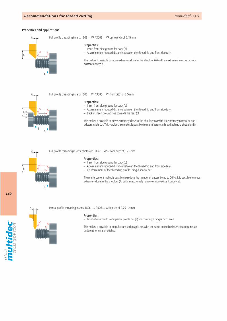
multidec®-CUT
142
a2
b
a2
bc
a2
b
a
A
AB
A
Recommendations for thread cutting
Properties:– Insert front side ground far back (b)– At a minimum reduced distance between the thread tip and front side (a2)
This makes it possible to move extremely close to the shoulder (A) with an extremely narrow or non-existent undercut.
Properties:– Insert front side ground far back (b)– At a minimum reduced distance between the thread tip and front side (a2)– Back of insert ground free towards the rear (c)
This makes it possible to move extremely close to the shoulder (A) with an extremely narrow or non-existent undercut. This version also makes it possible to manufacture a thread behind a shoulder (B).
Properties:– Insert front side ground far back (b)– At a minimum reduced distance between the thread tip and front side (a2)– Reinforcement of the threading profile using a special cut
The reinforcement makes it possible to reduce the number of passes by up to 20 %. It is possible to move extremely close to the shoulder (A) with an extremely narrow or non-existent undercut.
Properties:– Front of insert with wide partial profile cut (a) for covering a bigger pitch area
This makes it possible to manufacture various pitches with the same indexable insert, but requires an undercut for smaller pitches.
Full profile threading inserts 1606… VP / 3006… VP up to pitch of 0.45 mm
Full profile threading inserts 1606… VP / 3006… VP from pitch of 0.5 mm
Full profile threading inserts, reinforced 3006… VP – from pitch of 0.25 mm
Partial profile threading inserts 1606… / 3006… with pitch of 0.25 – 2 mm
Properties and applications
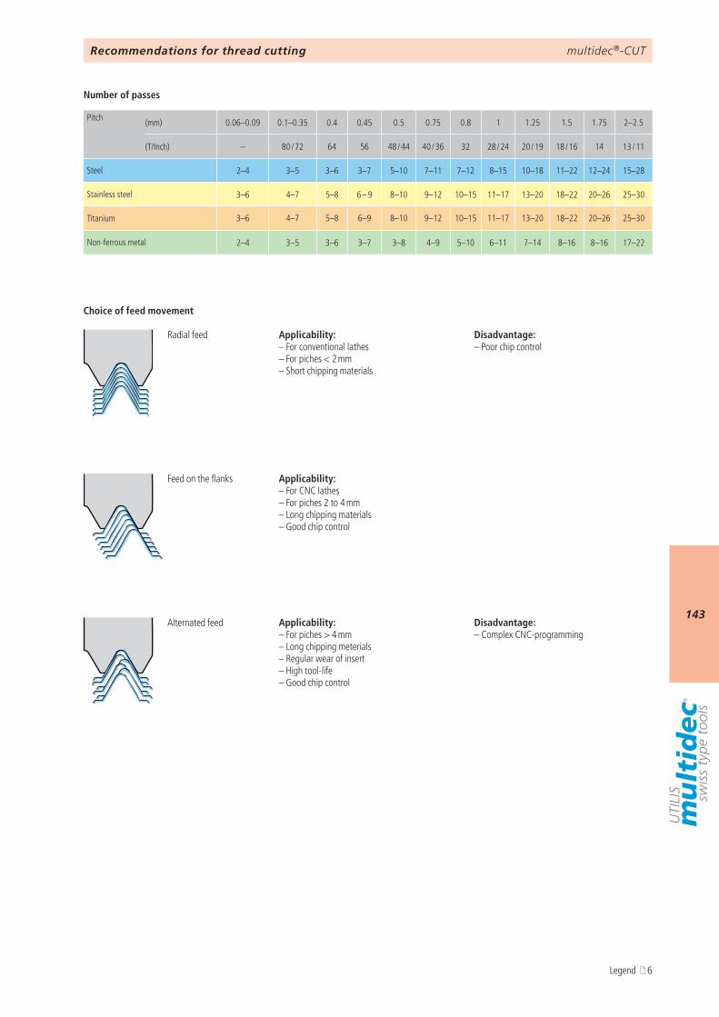
multidec®-CUT
143
0.06–0.09 0.1–0.35 0.4 0.45 0.5 0.75 0.8 1 1.25 1.5 1.75 2–2.5
– 80 / 72 64 56 48 / 44 40 / 36 32 28 / 24 20 / 19 18 / 16 14 13 / 11
2–4 3–5 3–6 3–7 5–10 7–11 7–12 8–15 10–18 11–22 12–24 15–28
3–6 4–7 5–8 6 – 9 8–10 9–12 10–15 11–17 13–20 18–22 20–26 25–30
3–6 4–7 5–8 6–9 8–10 9–12 10–15 11–17 13–20 18–22 20–26 25–30
2–4 3–5 3–6 3–7 3–8 4–9 5–10 6–11 7–14 8–16 8–16 17–22
Recommendations for thread cutting
Pitch (mm)
(T/Inch)
Steel
Stainless steel
Titanium
Non-ferrous metal
Applicability:– For conventional lathes – For piches < 2 mm – Short chipping materials
Disadvantage:– Poor chip control
Applicability:– For piches > 4 mm – Long chipping meterials – Regular wear of insert – High tool-life – Good chip control
Disadvantage:– Complex CNC-programming
Applicability:– For CNC lathes – For piches 2 to 4 mm – Long chipping materials – Good chip control
Radial feed
Feed on the flanks
Alternated feed
Choice of feed movement
Number of passes
Legend 6
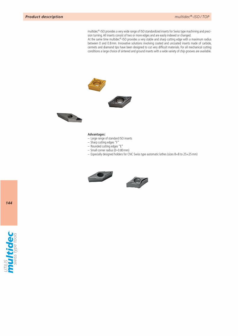
multidec®-ISO / TOP
144
Product description
multidec®-ISO provides a very wide range of ISO standardized inserts for Swiss type machining and preci-sion turning. All inserts consist of two or more edges and are easily indexed or changed.At the same time multidec®-ISO provides a very stable and sharp cutting edge with a maximum radius between 0 and 0.8 mm. Innovative solut ions involving coated and uncoated inserts made of carbide, cermets and diamond tips have been designed to cut very difficult materials. For all mechanical cutting conditions a large choice of sintered and ground inserts with a wide variety of chip grooves are available.
Advantages:– Large range of standard ISO inserts– Sharp cutting edges “F”– Rounded cutting edges “E”– Small corner radius (0–0.80 mm)– Especially designed holders for CNC Swiss type automatic lathes (sizes 8×8 to 25×25 mm)
multidec®-ISO / TOP
145
9 146 STANDARD-LINE
146
Article no. 126600 P4563213000 - 08 - 100 L A
147 149 173 199 221
Stahl unlegiertAcier non alliéSteel unalloyed
Stahl niedriglegiertAcier faibl. alliéSteel low alloyed
Stahl hochlegiertAcier fortem. alliéSteel high alloyed
TitanTitaneTitanium
Härte (HB)Dureté (HB)Hardness value (HB)
125–300 180 – 250 200 – 350 –
KategorieCatégrieCategory
I II III IV
BearbeitungUsinageMachining method
226 664
multidec®-ISO / TOPOverview
Technical information Application OD turning Product lines and accuracy classes of UTILIS Designation system (ISO)
Overview type CC… (80°) Overview type DC… (55°) Overview type VC… (35°) Overview type VP… (35°)
Cutting specification Accessories
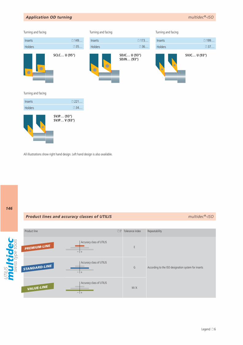
multidec®-ISO
146
34…
221…
37…
199…
SVJC… U (93°)
SVJP… (93°) SVJP… V (93°)
35…
149…
SCLC… U (95°)
36…
173…
SDJC… U (93°) SDJN… (93°)
7
– +
– +
– +
PREMIUM-LINE
VALUE-LINE
STANDARD-LINE
multidec®-ISO
Application OD turning
Holders
Holders
Holders Holders
Turning and facing Turning and facing
Turning and facing
Turning and facing
Inserts
Inserts Inserts Inserts
All illustrations show right hand design. Left hand design is also available.
Product lines and accuracy classes of UTILIS
Product line Tolerance index Repeatability
Accuracy class of UTILIS
E
According to the ISO designation system for inserts
Accuracy class of UTILIS
G
Accuracy class of UTILIS
M / X
Legend 6
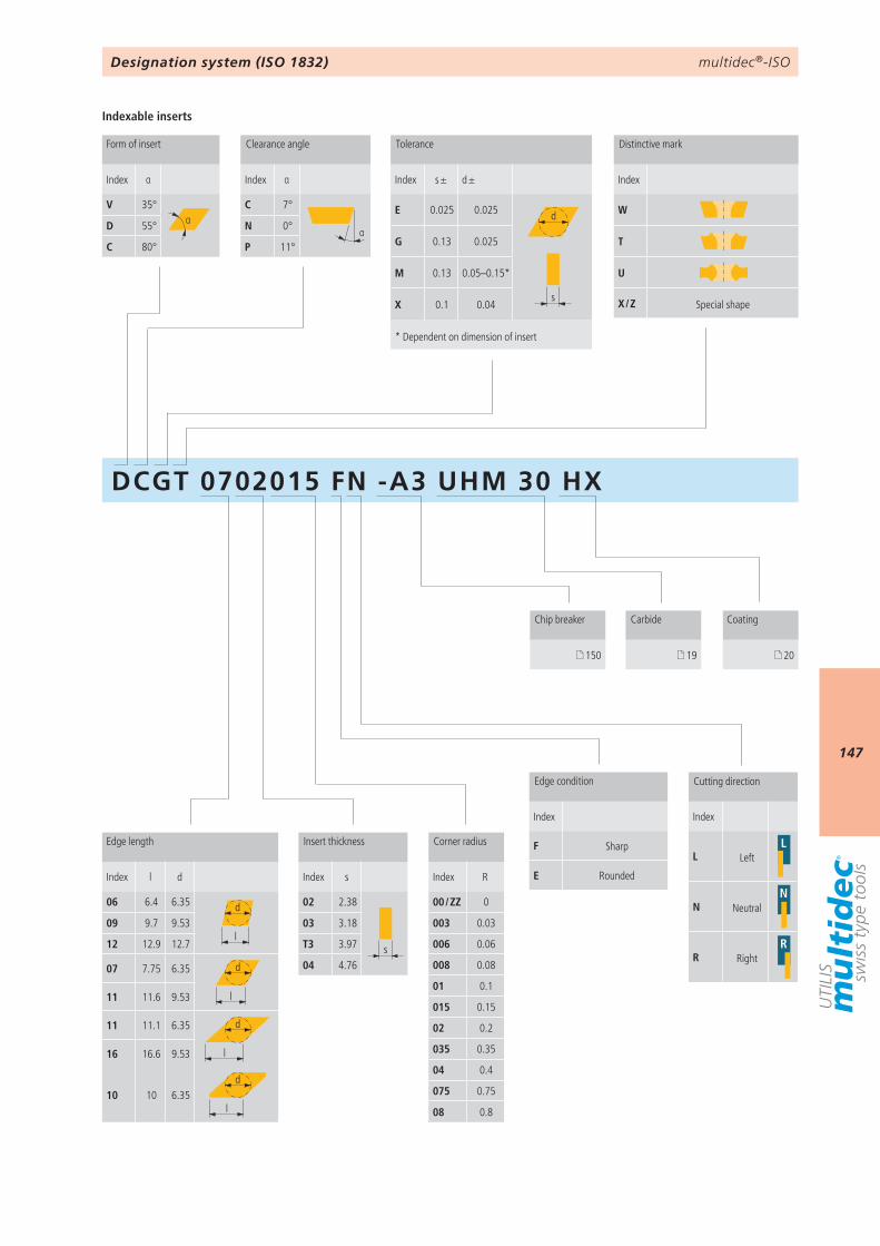
multidec®-ISO
147
DCGT 0702015 FN -A3 UHM 30 HX
Index α
V 35°αD 55°
C 80°
Index α
C 7°
αN 0°
P 11°
Index s ± d ±
E 0.025 0.025 d
s
G 0.13 0.025
M 0.13 0.05–0.15*
X 0.1 0.04
Index
W
T
U
X / Z
Index
F
E
Index
L L
N N
R R
Index l d
06 6.4 6.35 d
l09 9.7 9.53
12 12.9 12.7
07 7.75 6.35 d
l11 11.6 9.53
11 11.1 6.35 d
l16 16.6 9.53
10 10 6.35l
d
Index s
02 2.38
s
03 3.18
T3 3.97
04 4.76
Index R
00 / ZZ 0
003 0.03
006 0.06
008 0.08
01 0.1
015 0.15
02 0.2
035 0.35
04 0.4
075 0.75
08 0.8
150 19 20
Designation system (ISO 1832)
Form of insert Clearance angle Tolerance Distinctive mark
Edge length Insert thickness Corner radius
Edge condition Cutting direction
Chip breaker Carbide Coating
* Dependent on dimension of insert
Special shape
Left
Neutral
Right
Sharp
Rounded
Indexable inserts
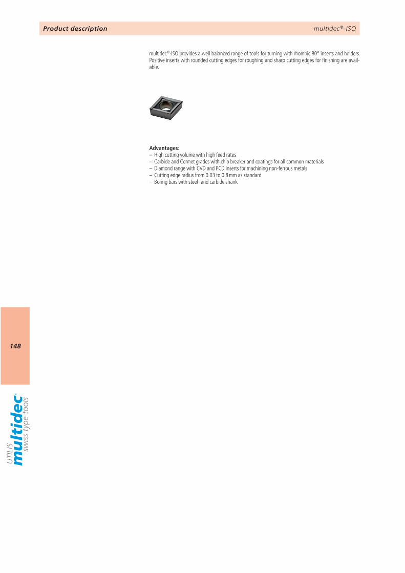
multidec®-ISO
148
Product description
multidec®-ISO provides a well balanced range of tools for turning with rhombic 80° inserts and holders. Positive inserts with rounded cutting edges for roughing and sharp cutting edges for finishing are avail-able.
Advantages:– High cutting volume with high feed rates– Carbide and Cermet grades with chip breaker and coatings for all common materials– Diamond range with CVD and PCD inserts for machining non-ferrous metals – Cutting edge radius from 0.03 to 0.8 mm as standard– Boring bars with steel- and carbide shank
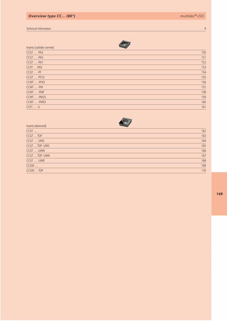
multidec®-ISO
149
9 CCGT … -PA3 150CCGT … -PA5 151CCGT … -PA7 152CCXT … PA9 153CCGT … -PF 154CCGT … -PF23 155CCMT … -PF43 156CCMT … -PM 157CCMT … -PMF 158CCMT … -PM25 159CCMT … -PM55 160CCET … -U 161
CCGT … 162CCGT … TOP 163CCGT … -UWS 164CCGT … TOP -UWS 165CCGT … -UWN 166CCGT … TOP -UWN 167CCGT … -UWR 168CCGW … 169CCGW … TOP 170
multidec®-ISOOverview type CC… (80°)
Technical information Inserts (carbide / cermet)
Inserts (diamond)
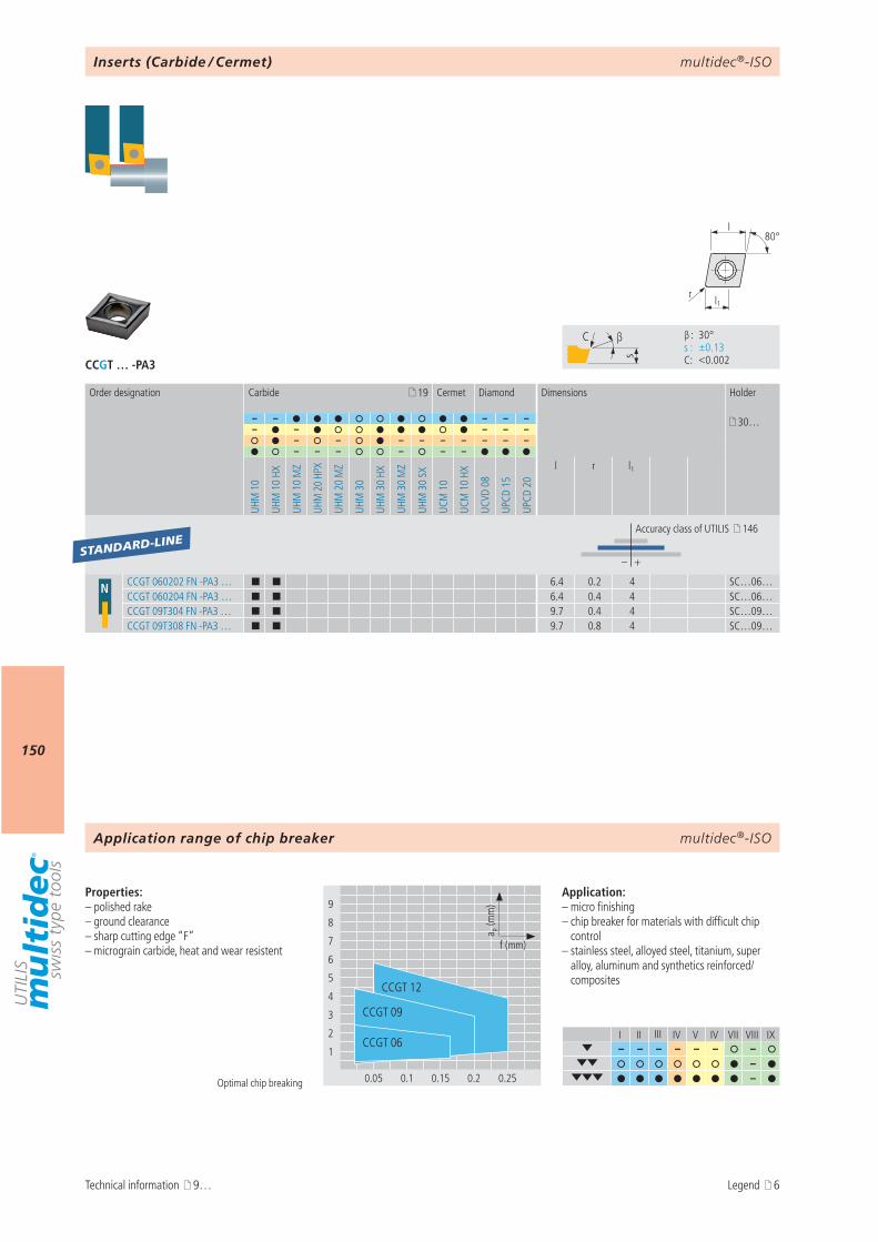
multidec®-ISO
150
CCGT … -PA3
I II III IV V IV VII VIII IX– – – – – – –
– –
s
C β
β : 30° s : ±0.13 C : <0.002
9
8
7
6
5
4
3
2
1
0.05 0.1 0.15 0.2 0.25
a p (m
m)
f (mm)
CCGT 06
CCGT 09
CCGT 12
l1r
80°l
19
– – – – – 30…– – – – –
– – – – – – – – –– – – – – –
UHM
10
UHM
10
HX
UHM
10
MZ
UHM
20
HPX
UHM
20
MZ
UHM
30
UHM
30
HX
UHM
30
MZ
UHM
30
SX
UCM
10
UCM
10
HX
UCVD
08
UPCD
15
UPCD
20
l r l1
– +
N CCGT 060202 FN -PA3 … ¢ ¢ 6.4 0.2 4 SC…06…CCGT 060204 FN -PA3 … ¢ ¢ 6.4 0.4 4 SC…06…CCGT 09T304 FN -PA3 … ¢ ¢ 9.7 0.4 4 SC…09…CCGT 09T308 FN -PA3 … ¢ ¢ 9.7 0.8 4 SC…09…
STANDARD-LINE
multidec®-ISO
Technical information 9…
Optimal chip breaking
Application range of chip breaker
Properties:– polished rake – ground clearance– sharp cutting edge “F”– micrograin carbide, heat and wear resistent
Application:– micro finishing– chip breaker for materials with difficult chip
control– stainless steel, alloyed steel, titanium, super
alloy, aluminum and synthetics reinforced/composites
Inserts (Carbide / Cermet)
Order designation Carbide Cermet Diamond Dimensions Holder
Accuracy class of UTILIS 146
Legend 6
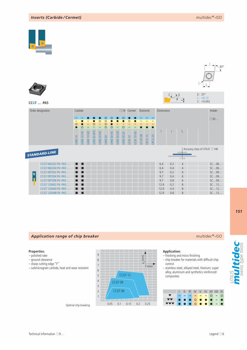
multidec®-ISO
151
CCGT … -PA5
I II III IV V IV VII VIII IX– – – – – – –
– –
9
8
7
6
5
4
3
2
1
0.05 0.1 0.15 0.2 0.25
a p (m
m)
f (mm)
CCGT 06
CCGT 09
CCGT 12
s
C β
β : 25° s : ±0.13 C : <0.002
l1r
80°l
19
– – – – – 30…– – – – –
– – – – – – – – –– – – – – –
UHM
10
UHM
10
HX
UHM
10
MZ
UHM
20
HPX
UHM
20
MZ
UHM
30
UHM
30
HX
UHM
30
MZ
UHM
30
SX
UCM
10
UCM
10
HX
UCVD
08
UPCD
15
UPCD
20
l r l1
– +
N
CCGT 060202 FN -PA5 … ¢ ¢ 6.4 0.2 4 SC…06…CCGT 060204 FN -PA5 … ¢ ¢ 6.4 0.4 4 SC…06…CCGT 09T302 FN -PA5 … ¢ ¢ 9.7 0.2 6 SC…09…CCGT 09T304 FN -PA5 … ¢ ¢ 9.7 0.4 6 SC…09…CCGT 09T308 FN -PA5 … ¢ ¢ 9.7 0.8 6 SC…09…CCGT 120402 FN -PA5 … ¢ ¢ 12.9 0.2 8 SC…12…CCGT 120404 FN -PA5 … ¢ ¢ 12.9 0.4 8 SC…12…CCGT 120408 FN -PA5 … ¢ ¢ 12.9 0.8 8 SC…12…
STANDARD-LINE
multidec®-ISO
Optimal chip breaking
Technical information 9…
Application range of chip breaker
Properties:– polished rake – ground clearance– sharp cutting edge “F”– submicrograin carbide, heat and wear resistent
Application:– finishing and micro finishing– chip breaker for materials with difficult chip
control– stainless steel, alloyed steel, titanium, super
alloy, aluminum and synthetics reinforced/composites
Inserts (Carbide / Cermet)
Order designation Carbide Cermet Diamond Dimensions Holder
Accuracy class of UTILIS 146
Legend 6
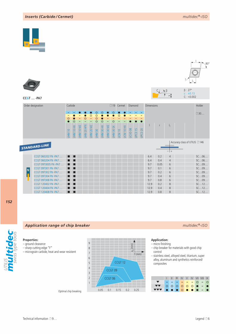
multidec®-ISO
152
CCGT … -PA7
I II III IV V IV VII VIII IX– – – – – – –
– –
9
8
7
6
5
4
3
2
1
0.05 0.1 0.15 0.2 0.25
a p (m
m)
f (mm)
CCGT 06
CCGT 09
CCGT 12
s
C β
β : 27° s : ±0.13 C : <0.002
l1r
80°l
19
– – – – – 30…– – – – –
– – – – – – – – –– – – – – –
UHM
10
UHM
10
HX
UHM
10
MZ
UHM
20
HPX
UHM
20
MZ
UHM
30
UHM
30
HX
UHM
30
MZ
UHM
30
SX
UCM
10
UCM
10
HX
UCVD
08
UPCD
15
UPCD
20
l r l1
– +
N
CCGT 060202 FN -PA7 … ¢ ¢ 6.4 0.2 4 SC…06…CCGT 060204 FN -PA7 … ¢ ¢ 6.4 0.4 4 SC…06…CCGT 09T3005 FN -PA7 … ¢ ¢ 9.7 0.05 6 SC…09…CCGT 09T301 FN -PA7 … ¢ ¢ 9.7 0.1 6 SC…09…CCGT 09T302 FN -PA7 … ¢ ¢ 9.7 0.2 6 SC…09…CCGT 09T304 FN -PA7 … ¢ ¢ 9.7 0.4 6 SC…09…CCGT 09T308 FN -PA7 … ¢ ¢ 9.7 0.8 6 SC…09…CCGT 120402 FN -PA7 … ¢ ¢ 12.9 0.2 8 SC…12…CCGT 120404 FN -PA7 … ¢ ¢ 12.9 0.4 8 SC…12…CCGT 120408 FN -PA7 … ¢ ¢ 12.9 0.8 8 SC…12…
STANDARD-LINE
multidec®-ISO
Optimal chip breaking
Properties:– ground clearance– sharp cutting edge “F”– micrograin carbide, heat and wear resistent
Application:– micro finishing– chip breaker for materials with good chip
control– stainless steel, alloyed steel, titanium, super
alloy, aluminum and synthetics reinforced/composites
Inserts (Carbide / Cermet)
Order designation Carbide Cermet Diamond Dimensions Holder
Accuracy class of UTILIS 146
Application range of chip breaker
Technical information 9… Legend 6
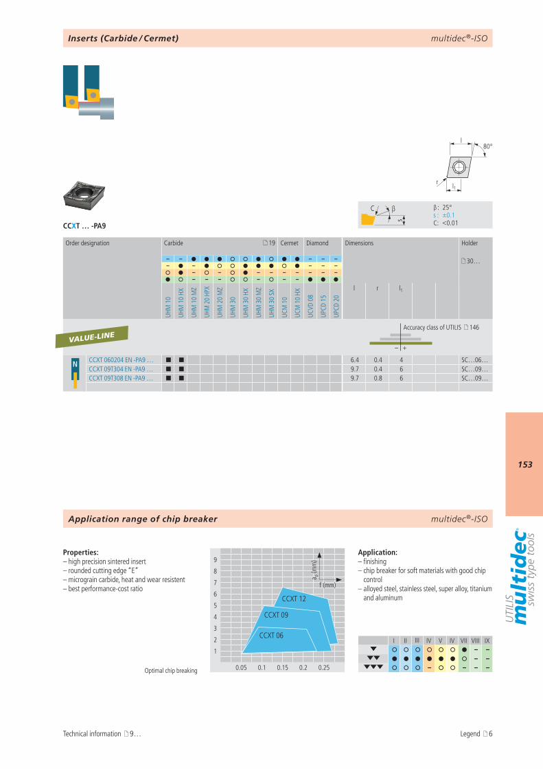
multidec®-ISO
153
CCXT … -PA9
I II III IV V IV VII VIII IX– –
– – – – – –
9
8
7
6
5
4
3
2
1
0.05 0.1 0.15 0.2 0.25
a p (m
m)
f (mm)
CCXT 12
CCXT 06
CCXT 09
s
C β
β : 25° s : ±0.1 C : <0.01
l1r
80°l
19
– – – – – 30…– – – – –
– – – – – – – – –– – – – – –
UHM
10
UHM
10
HX
UHM
10
MZ
UHM
20
HPX
UHM
20
MZ
UHM
30
UHM
30
HX
UHM
30
MZ
UHM
30
SX
UCM
10
UCM
10
HX
UCVD
08
UPCD
15
UPCD
20
l r l1
– +
N CCXT 060204 EN -PA9 … ¢ ¢ 6.4 0.4 4 SC…06…CCXT 09T304 EN -PA9 … ¢ ¢ 9.7 0.4 6 SC…09…CCXT 09T308 EN -PA9 … ¢ ¢ 9.7 0.8 6 SC…09…
VALUE-LINE
multidec®-ISO
Optimal chip breaking
Properties:– high precision sintered insert– rounded cutting edge “E”– micrograin carbide, heat and wear resistent– best performance-cost ratio
Application:– finishing– chip breaker for soft materials with good chip
control– alloyed steel, stainless steel, super alloy, titanium
and aluminum
Inserts (Carbide / Cermet)
Order designation Carbide Cermet Diamond Dimensions Holder
Accuracy class of UTILIS 146
Application range of chip breaker
Technical information 9… Legend 6
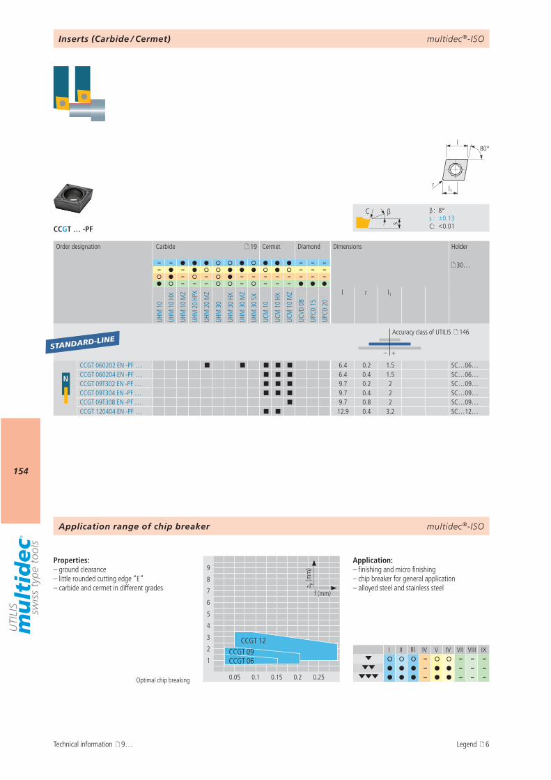
multidec®-ISO
154
CCGT … -PF
I II III IV V IV VII VIII IX– – – –
– – – – – – – –
9
8
7
6
5
4
3
2
1
0.05 0.1 0.15 0.2 0.25
CCGT 06
CCGT 12CCGT 09
a p (m
m)
f (mm)
s
C β
β : 8° s : ±0.13 C : <0.01
l1r
80°l
19
– – – – – 30…– – – – –
– – – – – – – – – –– – – – – – –
UHM
10
UHM
10
HX
UHM
10
MZ
UHM
20
HPX
UHM
20
MZ
UHM
30
UHM
30
HX
UHM
30
MZ
UHM
30
SX
UCM
10
UCM
10
HX
UCM
10
MZ
UCVD
08
UPCD
15
UPCD
20
l r l1
– +
N
CCGT 060202 EN -PF … ¢ ¢ ¢ ¢ ¢ 6.4 0.2 1.5 SC…06…CCGT 060204 EN -PF … ¢ ¢ ¢ 6.4 0.4 1.5 SC…06…CCGT 09T302 EN -PF … ¢ ¢ ¢ 9.7 0.2 2 SC…09…CCGT 09T304 EN -PF … ¢ ¢ ¢ 9.7 0.4 2 SC…09…CCGT 09T308 EN -PF … ¢ 9.7 0.8 2 SC…09…CCGT 120404 EN -PF … ¢ ¢ 12.9 0.4 3.2 SC…12…
STANDARD-LINE
multidec®-ISO
Optimal chip breaking
Properties:– ground clearance– little rounded cutting edge “E”– carbide and cermet in different grades
Application:– finishing and micro finishing– chip breaker for general application– alloyed steel and stainless steel
Inserts (Carbide / Cermet)
Order designation Carbide Cermet Diamond Dimensions Holder
Accuracy class of UTILIS 146
Application range of chip breaker
Technical information 9… Legend 6
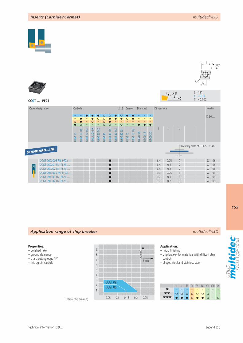
multidec®-ISO
155
CCGT … -PF23
I II III IV V IV VII VIII IX– – – – – – – – –
– – –
9
8
7
6
5
4
3
2
1
0.05 0.1 0.15 0.2 0.25
a p (m
m)
f (mm)
CCGT 06CCGT 09
s
C β
β : 12° s : ±0.13 C : <0.002
l1r
80°l
19
– – – – – 30…– – – – –
– – – – – – – – –– – – – – –
UHM
10
UHM
10
HX
UHM
10
MZ
UHM
20
HPX
UHM
20
MZ
UHM
30
UHM
30
HX
UHM
30
MZ
UHM
30
SX
UCM
10
UCM
10
HX
UCVD
08
UPCD
15
UPCD
20
l r l1
– +
N
CCGT 0602005 FN -PF23 … ¢ 6.4 0.05 2 SC…06…CCGT 060201 FN -PF23 … ¢ 6.4 0.1 2 SC…06…CCGT 060202 FN -PF23 … ¢ 6.4 0.2 2 SC…06…CCGT 09T3005 FN -PF23 … ¢ 9.7 0.05 3 SC…09…CCGT 09T301 FN -PF23 … ¢ 9.7 0.1 3 SC…09…CCGT 09T302 FN -PF23 … ¢ 9.7 0.2 3 SC…09…
STANDARD-LINE
multidec®-ISO
Optimal chip breaking
Properties:– polished rake – ground clearance– sharp cutting edge “F”– micrograin carbide
Application:– micro finishing– chip breaker for materials with difficult chip
control– alloyed steel and stainless steel
Inserts (Carbide / Cermet)
Order designation Carbide Cermet Diamond Dimensions Holder
Accuracy class of UTILIS 146
Application range of chip breaker
Technical information 9… Legend 6
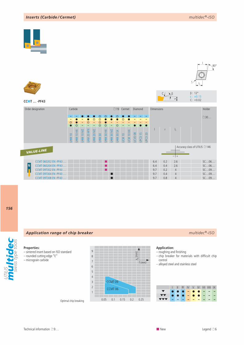
multidec®-ISO
156
CCMT … -PF43
I II III IV V IV VII VIII IX– – – –
– – – – – – – – – – – – –
9
8
7
6
5
4
3
2
1
0.05 0.1 0.15 0.2 0.25
a p (m
m)
f (mm)
CCMT 09
CCMT 06
s
C β
β : 12° s : ±0.13 C : <0.02
l1r
80°l
19
– – – – – 30…– – – – –
– – – – – – – – –– – – – – –
UHM
10
UHM
10
HX
UHM
10
MZ
UHM
20
HPX
UHM
20
MZ
UHM
30
UHM
30
HX
UHM
30
MZ
UHM
30
SX
UCM
10
UCM
10
HX
UCVD
08
UPCD
15
UPCD
20
l r l1
– +
NCCMT 060202 EN -PF43 … ¢ 6.4 0.2 2.6 SC…06…CCMT 060204 EN -PF43 … ¢ 6.4 0.4 2.6 SC…06…CCMT 09T302 EN -PF43 … ¢ 9.7 0.2 4 SC…09…CCMT 09T304 EN -PF43 … ¢ 9.7 0.4 4 SC…09…CCMT 09T308 EN -PF43 … ¢ 9.7 0.8 4 SC…09…
VALUE-LINE
multidec®-ISO
Optimal chip breaking
Properties:– sintered insert based on ISO standard– rounded cutting edge “E”– micrograin carbide
Application:– roughing and finishing– chip breaker for materials with difficult chip
control– alloyed steel and stainless steel
Inserts (Carbide / Cermet)
Order designation Carbide Cermet Diamond Dimensions Holder
Accuracy class of UTILIS 146
Application range of chip breaker
Technical information 9… ¢ New Legend 6
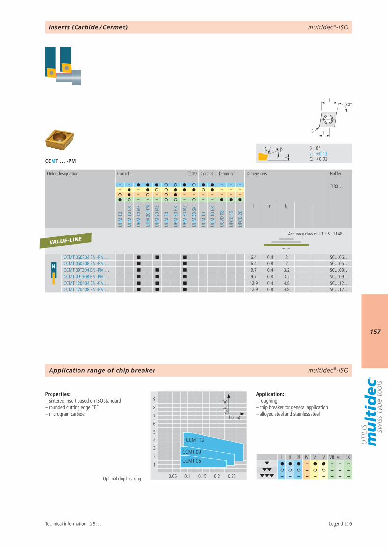
multidec®-ISO
157
CCMT … -PM
I II III IV V IV VII VIII IX– – – –
– – – – – – – – – – – – –
9
8
7
6
5
4
3
2
1
0.05 0.1 0.15 0.2 0.25
a p (m
m)
f (mm)
CCMT 06
CCMT 09
CCMT 12
s
C β
β : 8° s : ±0.13 C : <0.02
l1r
80°l
19
– – – – – 30…– – – – –
– – – – – – – – –– – – – – –
UHM
10
UHM
10
HX
UHM
10
MZ
UHM
20
HPX
UHM
20
MZ
UHM
30
UHM
30
HX
UHM
30
MZ
UHM
30
SX
UCM
10
UCM
10
HX
UCVD
08
UPCD
15
UPCD
20
l r l1
– +
N
CCMT 060204 EN -PM … ¢ ¢ ¢ 6.4 0.4 2 SC…06…CCMT 060208 EN -PM … ¢ ¢ 6.4 0.8 2 SC…06…CCMT 09T304 EN -PM … ¢ ¢ ¢ 9.7 0.4 3.2 SC…09…CCMT 09T308 EN -PM … ¢ ¢ ¢ 9.7 0.8 3.2 SC…09…CCMT 120404 EN -PM … ¢ ¢ ¢ 12.9 0.4 4.8 SC…12…CCMT 120408 EN -PM … ¢ ¢ ¢ 12.9 0.8 4.8 SC…12…
VALUE-LINE
multidec®-ISO
Optimal chip breaking
Properties:– sintered insert based on ISO standard– rounded cutting edge “E”– micrograin carbide
Application:– roughing– chip breaker for general application– alloyed steel and stainless steel
Inserts (Carbide / Cermet)
Order designation Carbide Cermet Diamond Dimensions Holder
Accuracy class of UTILIS 146
Application range of chip breaker
Technical information 9… Legend 6
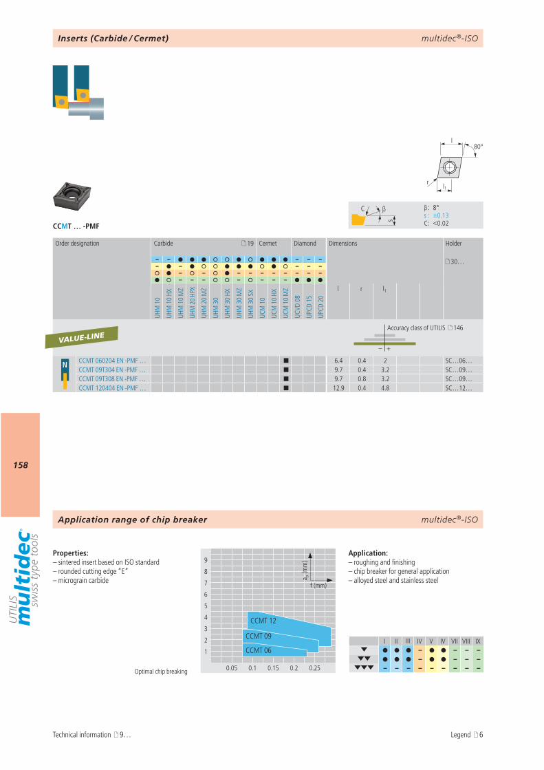
multidec®-ISO
158
CCMT … -PMF
I II III IV V IV VII VIII IX– – – –
– – – – – – – – – – – – –
9
8
7
6
5
4
3
2
1
0.05 0.1 0.15 0.2 0.25
a p (m
m)
f (mm)
CCMT 06
CCMT 09
CCMT 12
s
C β
β : 8° s : ±0.13 C : <0.02
l1r
80°l
19
– – – – – 30…– – – – –
– – – – – – – – – –– – – – – – –
UHM
10
UHM
10
HX
UHM
10
MZ
UHM
20
HPX
UHM
20
MZ
UHM
30
UHM
30
HX
UHM
30
MZ
UHM
30
SX
UCM
10
UCM
10
HX
UCM
10
MZ
UCVD
08
UPCD
15
UPCD
20
l r l1
– +
N CCMT 060204 EN -PMF … ¢ 6.4 0.4 2 SC…06…CCMT 09T304 EN -PMF … ¢ 9.7 0.4 3.2 SC…09…CCMT 09T308 EN -PMF … ¢ 9.7 0.8 3.2 SC…09…CCMT 120404 EN -PMF … ¢ 12.9 0.4 4.8 SC…12…
VALUE-LINE
multidec®-ISO
Optimal chip breaking
Properties:– sintered insert based on ISO standard– rounded cutting edge “E”– micrograin carbide
Application:– roughing and finishing– chip breaker for general application– alloyed steel and stainless steel
Inserts (Carbide / Cermet)
Order designation Carbide Cermet Diamond Dimensions Holder
Accuracy class of UTILIS 146
Application range of chip breaker
Technical information 9… Legend 6
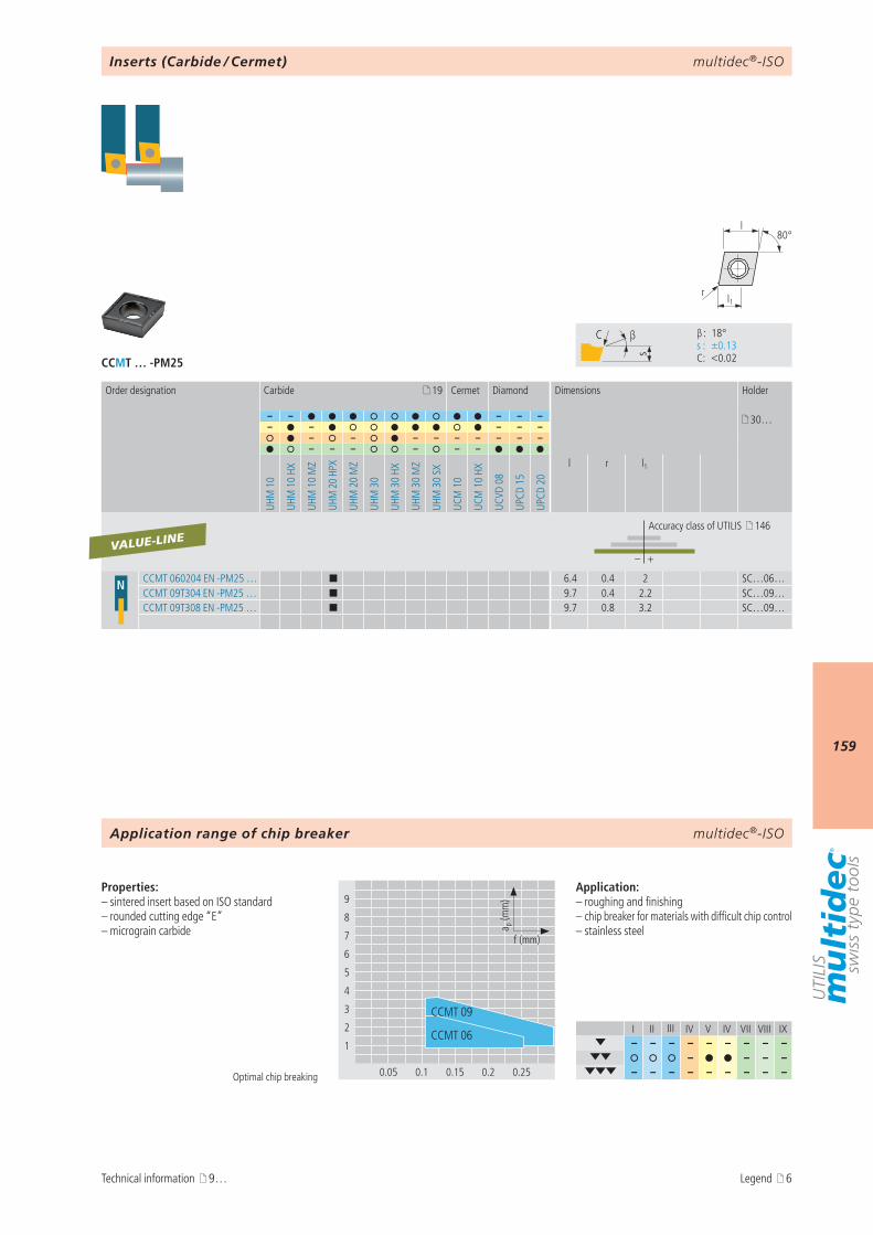
multidec®-ISO
159
CCMT … -PM25
I II III IV V IV VII VIII IX– – – – – – – – –
– – – – – – – – – – – – –
9
8
7
6
5
4
3
2
1
0.05 0.1 0.15 0.2 0.25
a p (m
m)
f (mm)
CCMT 09
CCMT 06
s
C β
β : 18° s : ±0.13 C : <0.02
l1r
80°l
19
– – – – – 30…– – – – –
– – – – – – – – –– – – – – –
UHM
10
UHM
10
HX
UHM
10
MZ
UHM
20
HPX
UHM
20
MZ
UHM
30
UHM
30
HX
UHM
30
MZ
UHM
30
SX
UCM
10
UCM
10
HX
UCVD
08
UPCD
15
UPCD
20
l r l1
– +
N CCMT 060204 EN -PM25 … ¢ 6.4 0.4 2 SC…06…CCMT 09T304 EN -PM25 … ¢ 9.7 0.4 2.2 SC…09…CCMT 09T308 EN -PM25 … ¢ 9.7 0.8 3.2 SC…09…
VALUE-LINE
multidec®-ISO
Optimal chip breaking
Properties:– sintered insert based on ISO standard– rounded cutting edge “E”– micrograin carbide
Application:– roughing and finishing– chip breaker for materials with difficult chip control– stainless steel
Inserts (Carbide / Cermet)
Order designation Carbide Cermet Diamond Dimensions Holder
Accuracy class of UTILIS 146
Application range of chip breaker
Technical information 9… Legend 6

multidec®-ISO
160
CCMT … -PM55
I II III IV V IV VII VIII IX– – – –
– – – – – – – – – – – – – – – – – –
9
8
7
6
5
4
3
2
1
0.05 0.1 0.15 0.2 0.25
a p (m
m)
f (mm)
CCMT 06
CCMT 09
CCMT 12
s
C β
β : 16° s : ±0.13 C : <0.02
l1r
80°l
19
– – – – – 30…– – – – –
– – – – – – – – –– – – – – –
UHM
10
UHM
10
HX
UHM
10
MZ
UHM
20
HPX
UHM
20
MZ
UHM
30
UHM
30
HX
UHM
30
MZ
UHM
30
SX
UCM
10
UCM
10
HX
UCVD
08
UPCD
15
UPCD
20
l r l1
– +
NCCMT 060204 EN -PM55 … ¢ 6.4 0.4 2.6 SC…06…CCMT 09T304 EN -PM55 … ¢ 9.7 0.4 3 SC…09…CCMT 09T308 EN -PM55 … ¢ 9.7 0.8 4 SC…09…CCMT120404 EN -PM55 … ¢ 12.9 0.4 4 SC…12…CCMT120408 EN -PM55 … ¢ 12.9 0.8 4.8 SC…12…
VALUE-LINE
multidec®-ISO
Optimal chip breaking
Properties:– sintered insert based on ISO standard– rounded cutting edge “E”– micrograin carbide
Application:– roughing– chip breaker for general application– stainless steel
Inserts (Carbide / Cermet)
Order designation Carbide Cermet Diamond Dimensions Holder
Accuracy class of UTILIS 146
Application range of chip breaker
Technical information 9… Legend 6
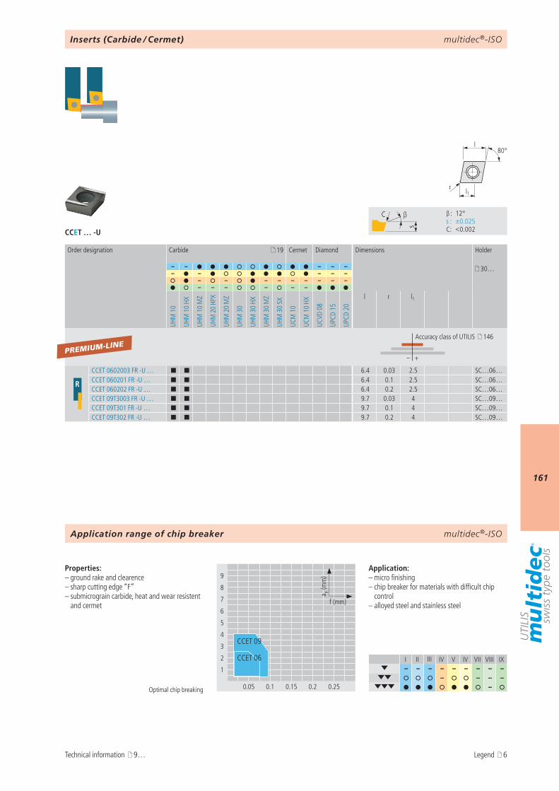
multidec®-ISO
161
CCET … -U
I II III IV V IV VII VIII IX– – – – – – – – –
– – – – –
9
8
7
6
5
4
3
2
1
0.05 0.1 0.15 0.2 0.25
a p (m
m)
f (mm)
CCET 06
CCET 09
s
C β
β : 12° s : ±0.025 C : <0.002
l1r
80°l
19
– – – – – 30…– – – – –
– – – – – – – – –– – – – – –
UHM
10
UHM
10
HX
UHM
10
MZ
UHM
20
HPX
UHM
20
MZ
UHM
30
UHM
30
HX
UHM
30
MZ
UHM
30
SX
UCM
10
UCM
10
HX
UCVD
08
UPCD
15
UPCD
20
l r l1
– +
R
CCET 0602003 FR -U … ¢ ¢ 6.4 0.03 2.5 SC…06…CCET 060201 FR -U … ¢ ¢ 6.4 0.1 2.5 SC…06…CCET 060202 FR -U … ¢ ¢ 6.4 0.2 2.5 SC…06…CCET 09T3003 FR -U … ¢ ¢ 9.7 0.03 4 SC…09…CCET 09T301 FR -U … ¢ ¢ 9.7 0.1 4 SC…09…CCET 09T302 FR -U … ¢ ¢ 9.7 0.2 4 SC…09…
PREMIUM-LINE
multidec®-ISO
Optimal chip breaking
Properties:– ground rake and clearence– sharp cutting edge “F”– submicrograin carbide, heat and wear resistent
and cermet
Application:– micro finishing– chip breaker for materials with difficult chip
control– alloyed steel and stainless steel
Inserts (Carbide / Cermet)
Order designation Carbide Cermet Diamond Dimensions Holder
Accuracy class of UTILIS 146
Application range of chip breaker
Technical information 9… Legend 6
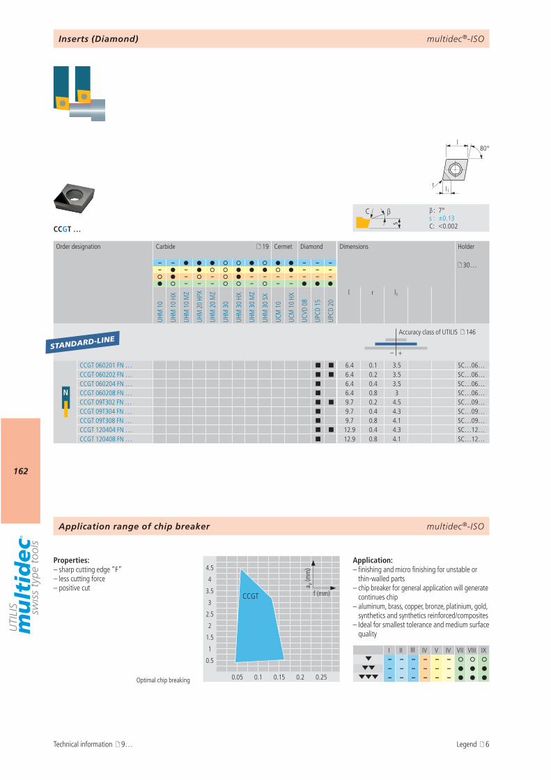
multidec®-ISO
162
CCGT …
I II III IV V IV VII VIII IX– – – – – –
– – – – – – – – – – – –
4.5
4
3.5
3
2.5
2
1.5
1
0.5
0.05 0.1 0.15 0.2 0.25
a p (m
m)
f (mm)CCGT
s
C β
β : 7° s : ±0.13 C : <0.002
r
80°l
l1
19
– – – – – 30…– – – – –
– – – – – – – – –– – – – – –
UHM
10
UHM
10
HX
UHM
10
MZ
UHM
20
HPX
UHM
20
MZ
UHM
30
UHM
30
HX
UHM
30
MZ
UHM
30
SX
UCM
10
UCM
10
HX
UCVD
08
UPCD
15
UPCD
20
l r l1
– +
N
CCGT 060201 FN … ¢ ¢ 6.4 0.1 3.5 SC…06…CCGT 060202 FN … ¢ ¢ 6.4 0.2 3.5 SC…06…CCGT 060204 FN … ¢ 6.4 0.4 3.5 SC…06…CCGT 060208 FN … ¢ 6.4 0.8 3 SC…06…CCGT 09T302 FN … ¢ ¢ 9.7 0.2 4.5 SC…09…CCGT 09T304 FN … ¢ 9.7 0.4 4.3 SC…09…CCGT 09T308 FN … ¢ 9.7 0.8 4.1 SC…09…CCGT 120404 FN … ¢ ¢ 12.9 0.4 4.3 SC…12…CCGT 120408 FN … ¢ 12.9 0.8 4.1 SC…12…
STANDARD-LINE
multidec®-ISO
Optimal chip breaking
Properties:– sharp cutting edge “F”– less cutting force– positive cut
Application:– finishing and micro finishing for unstable or
thin-walled parts– chip breaker for general application will generate
continues chip– aluminum, brass, copper, bronze, platinium, gold,
synthetics and synthetics reinforced/composites– Ideal for smallest tolerance and medium surface
quality
Inserts (Diamond)
Order designation Carbide Cermet Diamond Dimensions Holder
Accuracy class of UTILIS 146
Application range of chip breaker
Technical information 9… Legend 6
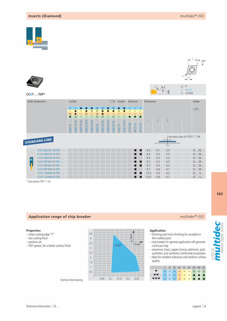
multidec®-ISO
163
CCGT … TOP*
I II III IV V IV VII VIII IX– – – – – –
– – – – – – – – – – – –
4.5
4
3.5
3
2.5
2
1.5
1
0.5
0.05 0.1 0.15 0.2 0.25
a p (m
m)
f (mm)CCGT
s
C β
β : 7° s : ±0.13 C : <0.002
r
80°l
l1
19
– – – – – 30…– – – – –
– – – – – – – – –– – – – – –
UHM
10
UHM
10
HX
UHM
10
MZ
UHM
20
HPX
UHM
20
MZ
UHM
30
UHM
30
HX
UHM
30
MZ
UHM
30
SX
UCM
10
UCM
10
HX
UCVD
08
UPCD
15
UPCD
20
l r l1
– +
N
CCGT 060201 FN TOP … ¢ ¢ 6.4 0.1 3.5 SC…06…CCGT 060202 FN TOP … ¢ ¢ 6.4 0.2 3.5 SC…06…CCGT 060204 FN TOP … ¢ 6.4 0.4 3.5 SC…06…CCGT 09T302 FN TOP … ¢ ¢ 9.7 0.2 4.5 SC…09…CCGT 09T304 FN TOP … ¢ ¢ 9.7 0.4 4.3 SC…09…CCGT 09T308 FN TOP … ¢ 9.7 0.8 4.1 SC…09…CCGT 120404 FN TOP … ¢ ¢ 12.9 0.4 4.3 SC…12…CCGT 120408 FN TOP … ¢ ¢ 12.9 0.8 4.1 SC…12…
STANDARD-LINE
multidec®-ISO
Optimal chip breaking
Properties:– sharp cutting edge “F”– less cutting force– positive cut– TOP system, for a better surface finish
Application:– finishing and micro finishing for unstable or
thin-walled parts– chip breaker for general application will generate
continues chip– aluminum, brass, copper, bronze, platinium, gold,
synthetics and synthetics reinforced/composites– Ideal for smallest tolerance and medium surface
quality
Inserts (Diamond)
Order designation Carbide Cermet Diamond Dimensions Holder
Accuracy class of UTILIS 146
Application range of chip breaker
Technical information 9…
* Description TOP 25
Legend 6
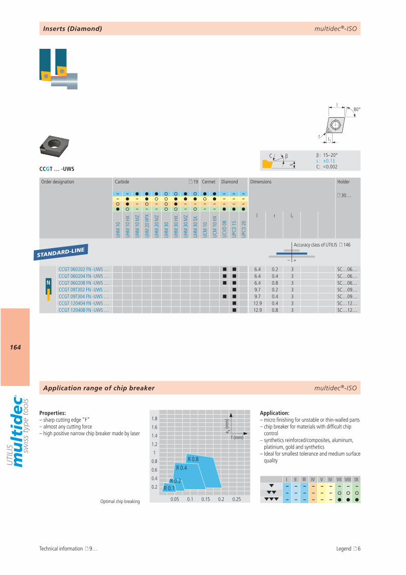
multidec®-ISO
164
CCGT … -UWS
I II III IV V IV VII VIII IX– – – – – – – – –
– – – – – – – – – – – –
s
C β
β : 15–20° s : ±0.13 C : <0.002
1.8
1.6
1.4
1.2
1
0.8
0.6
0.4
0.2
0.05 0.1 0.15 0.2 0.25
a p (m
m)
f (mm)
R 0.4
R 0.1
R 0.8
R 0.2
r
80°l
l1
19
– – – – – 30…– – – – –
– – – – – – – – –– – – – – –
UHM
10
UHM
10
HX
UHM
10
MZ
UHM
20
HPX
UHM
20
MZ
UHM
30
UHM
30
HX
UHM
30
MZ
UHM
30
SX
UCM
10
UCM
10
HX
UCVD
08
UPCD
15
UPCD
20
l r l1
– +
N
CCGT 060202 FN -UWS … ¢ ¢ 6.4 0.2 3 SC…06…CCGT 060204 FN -UWS … ¢ ¢ 6.4 0.4 3 SC…06…CCGT 060208 FN -UWS … ¢ ¢ 6.4 0.8 3 SC…06…CCGT 09T302 FN -UWS … ¢ 9.7 0.2 3 SC…09…CCGT 09T304 FN -UWS … ¢ ¢ 9.7 0.4 3 SC…09…CCGT 120404 FN -UWS … ¢ 12.9 0.4 3 SC…12…CCGT 120408 FN -UWS … ¢ 12.9 0.8 3 SC…12…
STANDARD-LINE
multidec®-ISO
Optimal chip breaking
Properties:– sharp cutting edge “F”– almost any cutting force– high positive narrow chip breaker made by laser
Application:– micro finishing for unstable or thin-walled parts– chip breaker for materials with difficult chip
control– synthetics reinforced/composites, aluminum,
platinium, gold and synthetics– Ideal for smallest tolerance and medium surface
quality
Inserts (Diamond)
Order designation Carbide Cermet Diamond Dimensions Holder
Accuracy class of UTILIS 146
Application range of chip breaker
Technical information 9… Legend 6
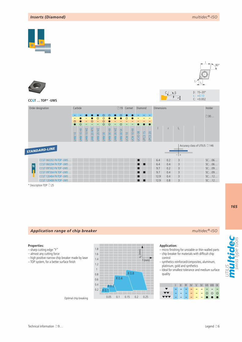
multidec®-ISO
165
CCGT … TOP* -UWS
I II III IV V IV VII VIII IX– – – – – – – – –
– – – – – – – – – – – –
s
C β
β : 15–20° s : ±0.13 C : <0.002
1.8
1.6
1.4
1.2
1
0.8
0.6
0.4
0.2
0.05 0.1 0.15 0.2 0.25
a p (m
m)
f (mm)
R 0.4
R 0.1
R 0.8
R 0.2
r
80°l
l1
19
– – – – – 30…– – – – –
– – – – – – – – –– – – – – –
UHM
10
UHM
10
HX
UHM
10
MZ
UHM
20
HPX
UHM
20
MZ
UHM
30
UHM
30
HX
UHM
30
MZ
UHM
30
SX
UCM
10
UCM
10
HX
UCVD
08
UPCD
15
UPCD
20
l r l1
– +
N
CCGT 060202 FN TOP -UWS … ¢ 6.4 0.2 3 SC…06…CCGT 060204 FN TOP -UWS … ¢ ¢ 6.4 0.4 3 SC…06…CCGT 09T302 FN TOP -UWS … ¢ 9.7 0.2 3 SC…09…CCGT 09T304 FN TOP -UWS … ¢ ¢ 9.7 0.4 3 SC…09…CCGT 120404 FN TOP -UWS … ¢ 12.9 0.4 3 SC…12…CCGT 120408 FN TOP -UWS … ¢ ¢ 12.9 0.8 3 SC…12…
STANDARD-LINE
multidec®-ISO
Optimal chip breaking
Properties:– sharp cutting edge “F”– almost any cutting force– high positive narrow chip breaker made by laser– TOP system, for a better surface finish
Application:– micro finishing for unstable or thin-walled parts– chip breaker for materials with difficult chip
control– synthetics reinforced/composites, aluminum,
platinium, gold and synthetics– Ideal for smallest tolerance and medium surface
quality
Inserts (Diamond)
Order designation Carbide Cermet Diamond Dimensions Holder
Accuracy class of UTILIS 146
Application range of chip breaker
Technical information 9…
* Description TOP 25
Legend 6
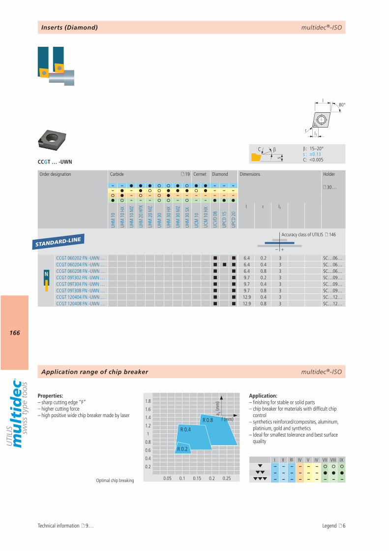
multidec®-ISO
166
CCGT … -UWN
I II III IV V IV VII VIII IX– – – – – –
– – – – – – – – – – – – – – –
s
C β
β : 15–20° s : ±0.13 C : <0.005
1.8
1.6
1.4
1.2
1
0.8
0.6
0.4
0.2
0.05 0.1 0.15 0.2 0.25
R 0.4
R 0.8
R 0.2
a p (m
m)
f (mm)
r
80°l
l1
19
– – – – – 30…– – – – –
– – – – – – – – –– – – – – –
UHM
10
UHM
10
HX
UHM
10
MZ
UHM
20
HPX
UHM
20
MZ
UHM
30
UHM
30
HX
UHM
30
MZ
UHM
30
SX
UCM
10
UCM
10
HX
UCVD
08
UPCD
15
UPCD
20
l r l1
– +
N
CCGT 060202 FN -UWN … ¢ ¢ 6.4 0.2 3 SC…06…CCGT 060204 FN -UWN … ¢ ¢ ¢ 6.4 0.4 3 SC…06…CCGT 060208 FN -UWN … ¢ ¢ 6.4 0.8 3 SC…06…CCGT 09T302 FN -UWN … ¢ ¢ 9.7 0.2 3 SC…09…CCGT 09T304 FN -UWN … ¢ ¢ 9.7 0.4 3 SC…09…CCGT 09T308 FN -UWN … ¢ ¢ 9.7 0.8 3 SC…09…CCGT 120404 FN -UWN … ¢ ¢ 12.9 0.4 3 SC…12…CCGT 120408 FN -UWN … ¢ ¢ 12.9 0.8 3 SC…12…
STANDARD-LINE
multidec®-ISO
Optimal chip breaking
Properties:– sharp cutting edge “F”– higher cutting force– high positive wide chip breaker made by laser
Application:– finishing for stable or solid parts– chip breaker for materials with difficult chip
control– synthetics reinforced/composites, aluminum,
platinium, gold and synthetics– Ideal for smallest tolerance and best surface
quality
Inserts (Diamond)
Order designation Carbide Cermet Diamond Dimensions Holder
Accuracy class of UTILIS 146
Application range of chip breaker
Technical information 9… Legend 6
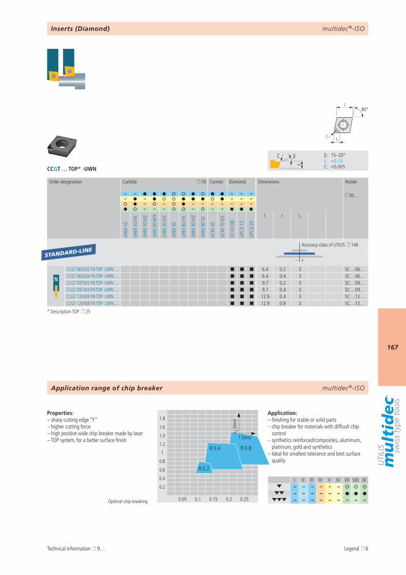
multidec®-ISO
167
CCGT … TOP* -UWN
I II III IV V IV VII VIII IX– – – – – –
– – – – – – – – – – – – – – –
s
C β
β : 15–20° s : ±0.13 C : <0.005
1.8
1.6
1.4
1.2
1
0.8
0.6
0.4
0.2
0.05 0.1 0.15 0.2 0.25
R 0.4 R 0.8
R 0.2
a p (m
m)
f (mm)
r
80°l
l1
19
– – – – – 30…– – – – –
– – – – – – – – –– – – – – –
UHM
10
UHM
10
HX
UHM
10
MZ
UHM
20
HPX
UHM
20
MZ
UHM
30
UHM
30
HX
UHM
30
MZ
UHM
30
SX
UCM
10
UCM
10
HX
UCVD
08
UPCD
15
UPCD
20
l r l1
– +
N
CCGT 060202 FN TOP -UWN … ¢ ¢ ¢ 6.4 0.2 3 SC…06…CCGT 060204 FN TOP -UWN … ¢ ¢ ¢ 6.4 0.4 3 SC…06…CCGT 09T302 FN TOP- UWN … ¢ ¢ ¢ 9.7 0.2 3 SC…09…CCGT 09T304 FN TOP -UWN … ¢ ¢ ¢ 9.7 0.4 3 SC…09…CCGT 120404 FN TOP -UWN … ¢ ¢ ¢ 12.9 0.4 3 SC…12…CCGT 120408 FN TOP- UWN … ¢ ¢ ¢ 12.9 0.8 3 SC…12…
STANDARD-LINE
multidec®-ISO
Optimal chip breaking
Properties:– sharp cutting edge “F”– higher cutting force– high positive wide chip breaker made by laser– TOP system, for a better surface finish
Application:– finishing for stable or solid parts– chip breaker for materials with difficult chip
control– synthetics reinforced/composites, aluminum,
platinium, gold and synthetics– Ideal for smallest tolerance and best surface
quality
Inserts (Diamond)
Order designation Carbide Cermet Diamond Dimensions Holder
Accuracy class of UTILIS 146
Application range of chip breaker
Technical information 9…
* Description TOP 25
Legend 6

multidec®-ISO
168
3.6
3.2
2.8
2.4
2
1.6
1.2
0.8
0.4
0.1 0.2 0.3 0.4 0.5
a p (m
m)
f (mm)
CCGT … -UWR
I II III IV V IV VII VIII IX– – – – – –
– – – – – – – – – – – – – – –
s
C β
β : 15–20° s : ±0.13 C : <0.005
r
80°l
l1
19
– – – – – 30…– – – – –
– – – – – – – – –– – – – – –
UHM
10
UHM
10
HX
UHM
10
MZ
UHM
20
HPX
UHM
20
MZ
UHM
30
UHM
30
HX
UHM
30
MZ
UHM
30
SX
UCM
10
UCM
10
HX
UCVD
08
UPCD
15
UPCD
20
l r l1
– +
N CCGT 060204 FN -UWR … ¢ 6.4 0.4 3 SC…06…CCGT 09T304 FN -UWR … ¢ 9.7 0.4 3 SC…09…CCGT 09T308 FN -UWR … ¢ 9.7 0.8 3 SC…09…
STANDARD-LINE
multidec®-ISO
Optimal chip breaking
Properties:– sharp cutting edge “F”– higher cutting force– high positive wide chip breaker made by laser
Application:– finishing for stable or solid parts– chip breaker for materials with difficult chip
control– synthetics reinforced/composites, aluminum,
platinium, gold and synthetics– maximum chip to chip volume
Inserts (Diamond)
Order designation Carbide Cermet Diamond Dimensions Holder
Accuracy class of UTILIS 146
Application range of chip breaker
Technical information 9… Legend 6
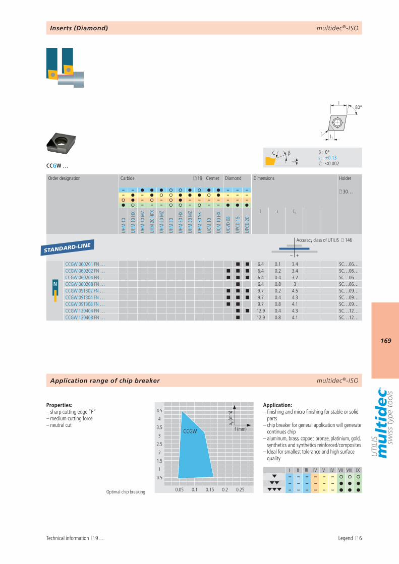
multidec®-ISO
169
s
C β
β : 0° s : ±0.13 C : <0.002CCGW …
I II III IV V IV VII VIII IX– – – – – –
– – – – – – – – – – – –
4.5
4
3.5
3
2.5
2
1.5
1
0.5
0.05 0.1 0.15 0.2 0.25
a p (m
m)
f (mm)CCGW
r
80°l
l1
19
– – – – – 30…– – – – –
– – – – – – – – –– – – – – –
UHM
10
UHM
10
HX
UHM
10
MZ
UHM
20
HPX
UHM
20
MZ
UHM
30
UHM
30
HX
UHM
30
MZ
UHM
30
SX
UCM
10
UCM
10
HX
UCVD
08
UPCD
15
UPCD
20
l r l1
– +
N
CCGW 060201 FN … ¢ ¢ 6.4 0.1 3.4 SC…06…CCGW 060202 FN … ¢ ¢ ¢ 6.4 0.2 3.4 SC…06…CCGW 060204 FN … ¢ ¢ ¢ 6.4 0.4 3.2 SC…06…CCGW 060208 FN … ¢ 6.4 0.8 3 SC…06…CCGW 09T302 FN … ¢ ¢ ¢ 9.7 0.2 4.5 SC…09…CCGW 09T304 FN … ¢ ¢ ¢ 9.7 0.4 4.3 SC…09…CCGW 09T308 FN … ¢ ¢ 9.7 0.8 4.1 SC…09…CCGW 120404 FN … ¢ ¢ 12.9 0.4 4.3 SC…12…CCGW 120408 FN … ¢ 12.9 0.8 4.1 SC…12…
STANDARD-LINE
multidec®-ISO
Optimal chip breaking
Properties:– sharp cutting edge “F”– medium cutting force– neutral cut
Application:– finishing and micro finishing for stable or solid
parts– chip breaker for general application will generate
continues chip– aluminum, brass, copper, bronze, platinium, gold,
synthetics and synthetics reinforced/composites– Ideal for smallest tolerance and high surface
quality
Inserts (Diamond)
Order designation Carbide Cermet Diamond Dimensions Holder
Accuracy class of UTILIS 146
Application range of chip breaker
Technical information 9… Legend 6
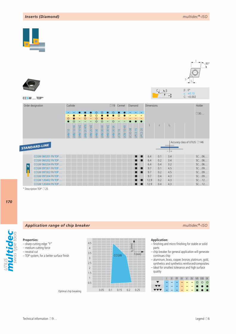
multidec®-ISO
170
s
C β
β : 0° s : ±0.13 C : <0.002CCGW … TOP*
I II III IV V IV VII VIII IX– – – – – –
– – – – – – – – – – – –
4.5
4
3.5
3
2.5
2
1.5
1
0.5
0.05 0.1 0.15 0.2 0.25
a p (m
m)
f (mm)CCGW
r
80°l
l1
19
– – – – – 30…– – – – –
– – – – – – – – –– – – – – –
UHM
10
UHM
10
HX
UHM
10
MZ
UHM
20
HPX
UHM
20
MZ
UHM
30
UHM
30
HX
UHM
30
MZ
UHM
30
SX
UCM
10
UCM
10
HX
UCVD
08
UPCD
15
UPCD
20
l r l1
– +
N
CCGW 060201 FN TOP … ¢ ¢ 6.4 0.1 3.4 SC…06…CCGW 060202 FN TOP … ¢ ¢ 6.4 0.2 3.4 SC…06…CCGW 060204 FN TOP … ¢ 6.4 0.4 3.2 SC…06…CCGW 09T301 FN TOP … ¢ ¢ 9.7 0.1 4.5 SC…09…CCGW 09T302 FN TOP … ¢ ¢ 9.7 0.2 4.5 SC…09…CCGW 09T304 FN TOP … ¢ 9.7 0.4 4.3 SC…09…CCGW 120402 FN TOP … ¢ ¢ 12.9 0.2 4.3 SC…12…CCGW 120404 FN TOP … ¢ ¢ 12.9 0.4 4.3 SC…12…
STANDARD-LINE
multidec®-ISO
Optimal chip breaking
Properties:– sharp cutting edge “F”– medium cutting force– neutral cut– TOP system, for a better surface finish
Application:– finishing and micro finishing for stable or solid
parts– chip breaker for general application will generate
continues chip– aluminum, brass, copper, bronze, platinium, gold,
synthetics and synthetics reinforced/composites– Ideal for smallest tolerance and high surface
quality
Inserts (Diamond)
Order designation Carbide Cermet Diamond Dimensions Holder
Accuracy class of UTILIS 146
Application range of chip breaker
Technical information 9…
* Description TOP 25
Legend 6

multidec®-ISO
171
AttentionPlease note the legend 6…
Notes
multidec®-ISO
172
Product description
multidec®-ISO provides a well balanced range of tools for turning with rhombic 55° inserts and holders. Positive inserts with rounded cutting edges for roughing and sharp cutting edges for finishing are avail-able.
Advantages:– Carbide and Cermet grades with chip breaker and coatings for all common materials– Diamond range with CVD and PCD inserts for machining non-ferrous metals– Cutting edge radius from 0.03 to 0.8 mm as standard– Boring bars with steel- and carbide shanks
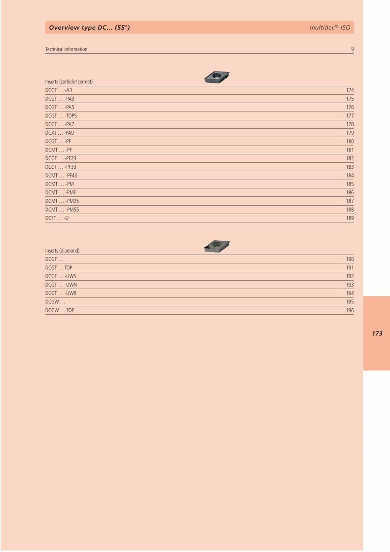
multidec®-ISO
173
9 DCGT … -A3 174DCGT … -PA3 175DCGT … -PA5 176DCGT … -TOP5 177DCGT … -PA7 178DCXT … -PA9 179DCGT … -PF 180DCMT … -PF 181DCGT … -PF23 182DCGT … -PF33 183DCMT … -PF43 184DCMT … -PM 185DCMT … -PMF 186DCMT … -PM25 187DCMT … -PM55 188DCET … -U 189
DCGT … 190DCGT … TOP 191DCGT … -UWS 192DCGT … -UWN 193DCGT … -UWR 194DCGW … 195DCGW … TOP 196
multidec®-ISOOverview type DC… (55°)
Technical information Inserts (carbide / cermet)
Inserts (diamond)

multidec®-ISO
174
I II III IV V IV VII VIII IX– – – – – – – – –
– –
DCGT … -A3
9
8
7
6
5
4
3
2
1
0.05 0.1 0.15 0.2 0.25
a p (m
m)
f (mm)DCGT 11
DCGT 07
s
C β
β : 30° s : ±0.13 C : <0.002
l1r
55°l
19
– – – – – 30…– – – – –
– – – – – – – – –– – – – – –
UHM
10
UHM
10
HX
UHM
10
MZ
UHM
20
HPX
UHM
20
MZ
UHM
30
UHM
30
HX
UHM
30
MZ
UHM
30
SX
UCM
10
UCM
10
HX
UCVD
08
UPCD
15
UPCD
20
l r l1
– +
N
DCGT 0702006 FN -A3 … ¢ ¢ ¢ 7.75 0.06 4.1 SD…07…DCGT 0702015 FN -A3 … ¢ ¢ ¢ 7.75 0.15 4.1 SD…07…DCGT 0702035 FN -A3 … ¢ ¢ ¢ 7.75 0.35 4.1 SD…07…DCGT 11T3008 FN -A3 … ¢ ¢ ¢ 11.6 0.08 7.2 SD…11…DCGT 11T3015 FN -A3 … ¢ ¢ ¢ 11.6 0.15 7.2 SD…11…DCGT 11T3035 FN -A3 … ¢ ¢ ¢ 11.6 0.35 7.2 SD…11…
STANDARD-LINE
multidec®-ISO
Optimal chip breaking
Properties:– polished rake – ground clearance– sharp cutting edge “F”– submicrograin carbide, heat and wear resistent
Application:– micro finishing– chip breaker for general application– stainless steel, alloyed steel, titanium, super
alloy, aluminum and synthetics reinforced/composites
Order designation Carbide Cermet Diamond Dimensions Holder
Accuracy class of UTILIS 146
Inserts (Carbide / Cermet)
Application range of chip breaker
Technical information 9… Legend 6
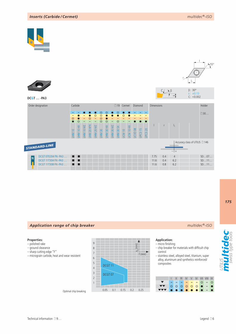
multidec®-ISO
175
DCGT … -PA3
I II III IV V IV VII VIII IX– – – – – – –
– –
9
8
7
6
5
4
3
2
1
0.05 0.1 0.15 0.2 0.25
a p (m
m)
f (mm)
DCGT 11
DCGT 07
s
C β
β : 30° s : ±0.13 C : <0.002
l1r
55°l
19
– – – – – 30…– – – – –
– – – – – – – – –– – – – – –
UHM
10
UHM
10
HX
UHM
10
MZ
UHM
20
HPX
UHM
20
MZ
UHM
30
UHM
30
HX
UHM
30
MZ
UHM
30
SX
UCM
10
UCM
10
HX
UCVD
08
UPCD
15
UPCD
20
l r l1
– +
N DCGT 070204 FN -PA3 … ¢ ¢ 7.75 0.4 4 SD…07…DCGT 11T304 FN -PA3 … ¢ ¢ 11.6 0.4 6.2 SD…11…DCGT 11T308 FN -PA3 … ¢ ¢ 11.6 0.8 6.2 SD…11…
STANDARD-LINE
multidec®-ISO
Optimal chip breaking
Properties:– polished rake – ground clearance– sharp cutting edge “F”– micrograin carbide, heat and wear resistent
Application:– micro finishing– chip breaker for materials with difficult chip
control– stainless steel, alloyed steel, titanium, super
alloy, aluminum and synthetics reinforced/composites
Order designation Carbide Cermet Diamond Dimensions Holder
Accuracy class of UTILIS 146
Inserts (Carbide / Cermet)
Application range of chip breaker
Technical information 9… Legend 6
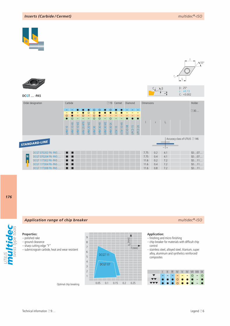
multidec®-ISO
176
DCGT … -PA5
I II III IV V IV VII VIII IX– – – – – – –
– –
9
8
7
6
5
4
3
2
1
0.05 0.1 0.15 0.2 0.25
a p (m
m)
f (mm)
DCGT 11
DCGT 07
s
C β
β : 25° s : ±0.13 C : <0.002
l1r
55°l
19
– – – – – 30…– – – – –
– – – – – – – – –– – – – – –
UHM
10
UHM
10
HX
UHM
10
MZ
UHM
20
HPX
UHM
20
MZ
UHM
30
UHM
30
HX
UHM
30
MZ
UHM
30
SX
UCM
10
UCM
10
HX
UCVD
08
UPCD
15
UPCD
20
l r l1
– +
NDCGT 070202 FN -PA5 … ¢ ¢ 7.75 0.2 4.1 SD…07…DCGT 070204 FN -PA5 … ¢ ¢ 7.75 0.4 4.1 SD…07…DCGT 11T302 FN -PA5 … ¢ ¢ 11.6 0.2 7.2 SD…11…DCGT 11T304 FN -PA5 … ¢ ¢ 11.6 0.4 7.2 SD…11…DCGT 11T308 FN -PA5 … ¢ ¢ 11.6 0.8 7.2 SD…11…
STANDARD-LINE
multidec®-ISO
Optimal chip breaking
Properties:– polished rake – ground clearance– sharp cutting edge “F”– submicrograin carbide, heat and wear resistent
Application:– finishing and micro finishing– chip breaker for materials with difficult chip
control– stainless steel, alloyed steel, titanium, super
alloy, aluminum and synthetics reinforced/composites
Order designation Carbide Cermet Diamond Dimensions Holder
Accuracy class of UTILIS 146
Inserts (Carbide / Cermet)
Application range of chip breaker
Technical information 9… Legend 6
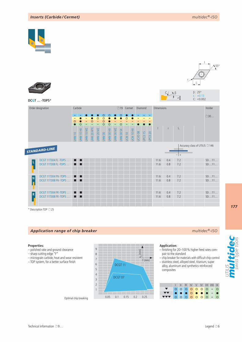
multidec®-ISO
177
DCGT … -TOP5*
I II III IV V IV VII VIII IX–
– –
9
8
7
6
5
4
3
2
1
0.05 0.1 0.15 0.2 0.25
a p (m
m)
f (mm)
DCGT 07
DCGT 11
s
C β
β : 25° s : ±0.13 C : <0.002
l1r
55°l
19
– – – – – 30…– – – – –
– – – – – – – – –– – – – – –
UHM
10
UHM
10
HX
UHM
10
MZ
UHM
20
HPX
UHM
20
MZ
UHM
30
UHM
30
HX
UHM
30
MZ
UHM
30
SX
UCM
10
UCM
10
HX
UCVD
08
UPCD
15
UPCD
20
l r l1
– +
L DCGT 11T304 FL -TOP5 … ¢ ¢ 11.6 0.4 7.2 SD…11…DCGT 11T308 FL -TOP5 … ¢ ¢ 11.6 0.8 7.2 SD…11…
N DCGT 11T304 FN -TOP5 … ¢ ¢ 11.6 0.4 7.2 SD…11…DCGT 11T308 FN -TOP5 … ¢ ¢ 11.6 0.8 7.2 SD…11…
R DCGT 11T304 FR -TOP5 … ¢ ¢ 11.6 0.4 7.2 SD…11…DCGT 11T308 FR -TOP5 … ¢ ¢ 11.6 0.8 7.2 SD…11…
STANDARD-LINE
multidec®-ISO
Optimal chip breaking
Properties:– polished rake and ground clearance– sharp cutting edge “F”– micrograin carbide, heat and wear resistent– TOP system, for a better surface finish
Application:– finishing for 20–100 % higher feed rates com-
pair to the standard– chip breaker for materials with difficult chip control– stainless steel, alloyed steel, titanium, super
alloy, aluminum and synthetics reinforced/composites
Order designation Carbide Cermet Diamond Dimensions Holder
Accuracy class of UTILIS 146
Inserts (Carbide / Cermet)
Application range of chip breaker
Technical information 9…
* Description TOP 25
Legend 6
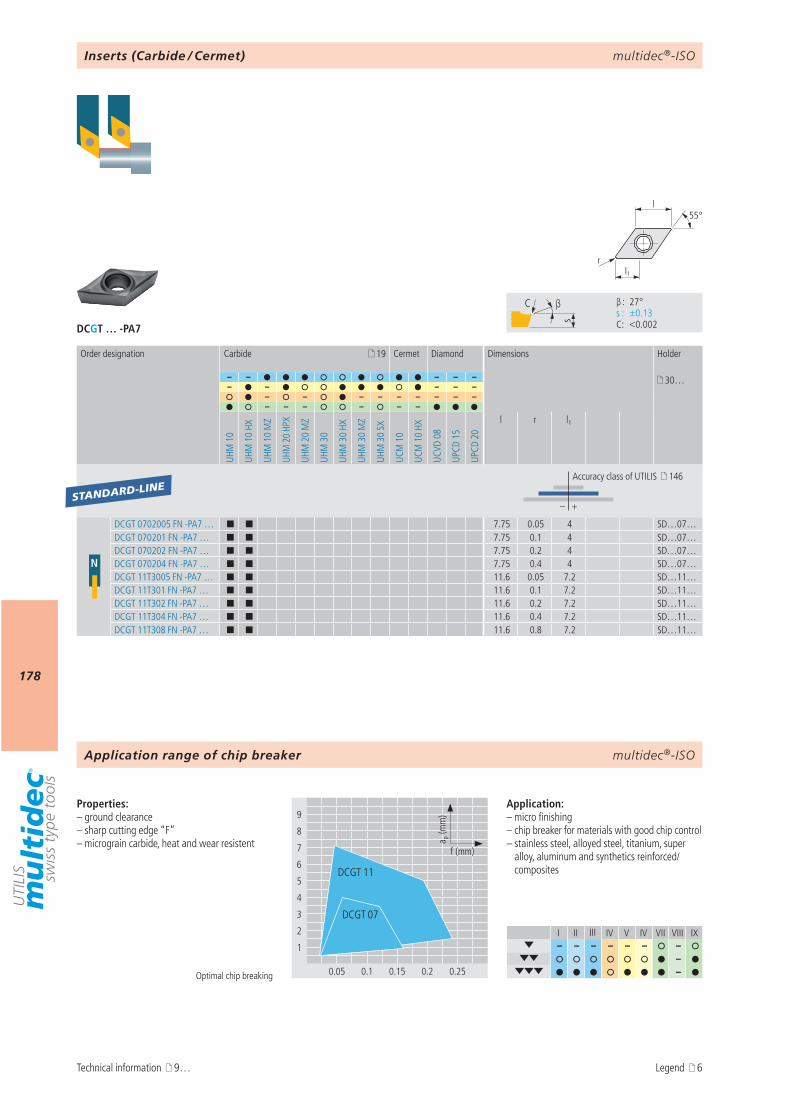
multidec®-ISO
178
DCGT … -PA7
I II III IV V IV VII VIII IX– – – – – – –
– –
9
8
7
6
5
4
3
2
1
0.05 0.1 0.15 0.2 0.25
a p (m
m)
f (mm)
DCGT 11
DCGT 07
s
C β
β : 27° s : ±0.13 C : <0.002
l1r
55°l
19
– – – – – 30…– – – – –
– – – – – – – – –– – – – – –
UHM
10
UHM
10
HX
UHM
10
MZ
UHM
20
HPX
UHM
20
MZ
UHM
30
UHM
30
HX
UHM
30
MZ
UHM
30
SX
UCM
10
UCM
10
HX
UCVD
08
UPCD
15
UPCD
20
l r l1
– +
N
DCGT 0702005 FN -PA7 … ¢ ¢ 7.75 0.05 4 SD…07…DCGT 070201 FN -PA7 … ¢ ¢ 7.75 0.1 4 SD…07…DCGT 070202 FN -PA7 … ¢ ¢ 7.75 0.2 4 SD…07…DCGT 070204 FN -PA7 … ¢ ¢ 7.75 0.4 4 SD…07…DCGT 11T3005 FN -PA7 … ¢ ¢ 11.6 0.05 7.2 SD…11…DCGT 11T301 FN -PA7 … ¢ ¢ 11.6 0.1 7.2 SD…11…DCGT 11T302 FN -PA7 … ¢ ¢ 11.6 0.2 7.2 SD…11…DCGT 11T304 FN -PA7 … ¢ ¢ 11.6 0.4 7.2 SD…11…DCGT 11T308 FN -PA7 … ¢ ¢ 11.6 0.8 7.2 SD…11…
STANDARD-LINE
multidec®-ISO
Optimal chip breaking
Properties:– ground clearance– sharp cutting edge “F”– micrograin carbide, heat and wear resistent
Application:– micro finishing– chip breaker for materials with good chip control– stainless steel, alloyed steel, titanium, super
alloy, aluminum and synthetics reinforced/composites
Order designation Carbide Cermet Diamond Dimensions Holder
Accuracy class of UTILIS 146
Inserts (Carbide / Cermet)
Application range of chip breaker
Technical information 9… Legend 6
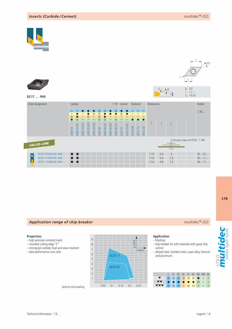
multidec®-ISO
179
DCXT … -PA9
I II III IV V IV VII VIII IX– –
– – – – – –
9
8
7
6
5
4
3
2
1
0.05 0.1 0.15 0.2 0.25
a p (m
m)
f (mm)
DCXT 07
DCXT 11
s
C β
β : 25° s : ±0.1 C : <0.01
l1r
55°l
19
– – – – – 30…– – – – –
– – – – – – – – –– – – – – –
UHM
10
UHM
10
HX
UHM
10
MZ
UHM
20
HPX
UHM
20
MZ
UHM
30
UHM
30
HX
UHM
30
MZ
UHM
30
SX
UCM
10
UCM
10
HX
UCVD
08
UPCD
15
UPCD
20
l r l1
– +
N DCXT 070204 EN -PA9 … ¢ ¢ 7.75 0.4 4 SD…07…DCXT 11T304 EN -PA9 … ¢ ¢ 11.6 0.4 7.2 SD…11…DCXT 11T308 EN -PA9 … ¢ ¢ 11.6 0.8 7.2 SD…11…
VALUE-LINE
multidec®-ISO
Optimal chip breaking
Properties:– high precision sintered insert– rounded cutting edge “E”– micrograin carbide, heat and wear resistent– best performance-cost ratio
Application:– finishing– chip breaker for soft materials with good chip
control– alloyed steel, stainless steel, super alloy, titanium
and aluminum
Order designation Carbide Cermet Diamond Dimensions Holder
Accuracy class of UTILIS 146
Inserts (Carbide / Cermet)
Application range of chip breaker
Technical information 9… Legend 6
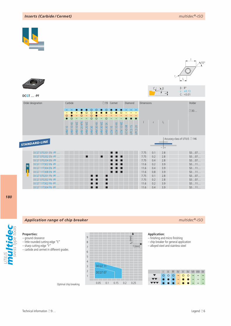
multidec®-ISO
180
DCGT … -PF
I II III IV V IV VII VIII IX– – – –
– – – – – – – –
9
8
7
6
5
4
3
2
1
0.05 0.1 0.15 0.2 0.25
a p (m
m)
f (mm)
DCGT 07
DCGT 11
s
C β
β : 8° s : ±0.13 C : <0.01
l1r
55°l
19
– – – – – 30…– – – – –
– – – – – – – – – –– – – – – – –
UHM
10
UHM
10
HX
UHM
10
MZ
UHM
20
HPX
UHM
20
MZ
UHM
30
UHM
30
HX
UHM
30
MZ
UHM
30
SX
UCM
10
UCM
10
HX
UCM
10
MZ
UCVD
08
UPCD
15
UPCD
20
l r l1
– +
N
DCGT 070201 EN -PF … ¢ ¢ 7.75 0.1 2.8 SD…07…DCGT 070202 EN -PF … ¢ ¢ ¢ ¢ ¢ 7.75 0.2 2.8 SD…07…DCGT 070204 EN -PF … ¢ ¢ ¢ 7.75 0.4 2.8 SD…07…DCGT 11T302 EN -PF … ¢ ¢ ¢ 11.6 0.2 3.9 SD…11…DCGT 11T304 EN -PF … ¢ ¢ ¢ 11.6 0.4 3.9 SD…11…DCGT 11T308 EN -PF … ¢ ¢ ¢ 11.6 0.8 3.9 SD…11…DCGT 070201 FN -PF … ¢ ¢ ¢ 7.75 0.1 2.8 SD…07…DCGT 070202 FN -PF … ¢ ¢ ¢ 7.75 0.2 2.8 SD…07…DCGT 11T302 FN -PF … ¢ ¢ ¢ 11.6 0.2 3.9 SD…11…DCGT 11T304 FN -PF … ¢ ¢ ¢ 11.6 0.4 3.9 SD…11…
STANDARD-LINE
multidec®-ISO
Optimal chip breaking
Properties:– ground clearance– little rounded cutting edge “E”– sharp cutting edge “F”– carbide and cermet in different grades
Application:– finishing and micro finishing– chip breaker for general application– alloyed steel and stainless steel
Inserts (Carbide / Cermet)
Order designation Carbide Cermet Diamond Dimensions Holder
Accuracy class of UTILIS 146
Application range of chip breaker
Technical information 9… Legend 6
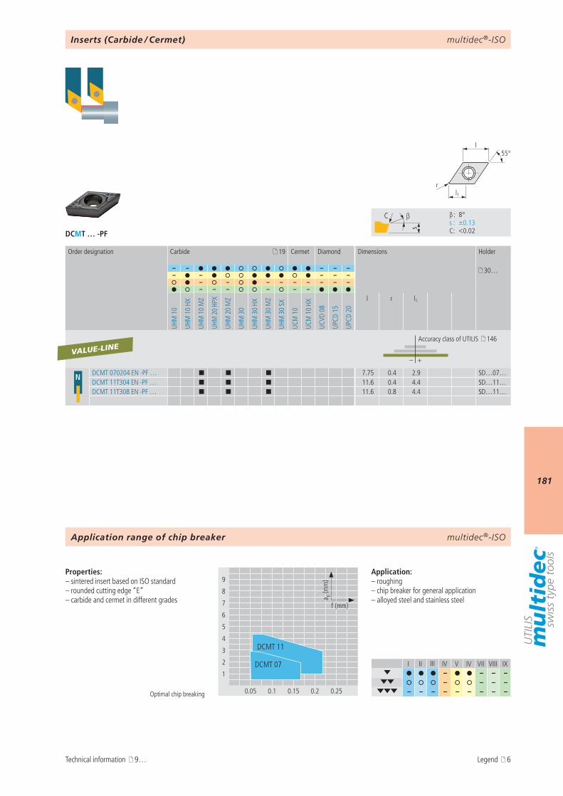
multidec®-ISO
181
DCMT … -PF
I II III IV V IV VII VIII IX– – – –
– – – – – – – – – – – – –
9
8
7
6
5
4
3
2
1
0.05 0.1 0.15 0.2 0.25
a p (m
m)
f (mm)
DCMT 11
DCMT 07
s
C β
β : 8° s : ±0.13 C : <0.02
l1r
55°l
19
– – – – – 30…– – – – –
– – – – – – – – –– – – – – –
UHM
10
UHM
10
HX
UHM
10
MZ
UHM
20
HPX
UHM
20
MZ
UHM
30
UHM
30
HX
UHM
30
MZ
UHM
30
SX
UCM
10
UCM
10
HX
UCVD
08
UPCD
15
UPCD
20
l r l1
– +
N DCMT 070204 EN -PF … ¢ ¢ ¢ 7.75 0.4 2.9 SD…07…DCMT 11T304 EN -PF … ¢ ¢ ¢ 11.6 0.4 4.4 SD…11…DCMT 11T308 EN -PF … ¢ ¢ ¢ 11.6 0.8 4.4 SD…11…
VALUE-LINE
multidec®-ISO
Optimal chip breaking
Properties:– sintered insert based on ISO standard– rounded cutting edge “E”– carbide and cermet in different grades
Application:– roughing– chip breaker for general application– alloyed steel and stainless steel
Order designation Carbide Cermet Diamond Dimensions Holder
Accuracy class of UTILIS 146
Inserts (Carbide / Cermet)
Application range of chip breaker
Technical information 9… Legend 6

multidec®-ISO
182
DCGT … -PF23
I II III IV V IV VII VIII IX– – – – – – – – –
– – –
9
8
7
6
5
4
3
2
1
0.05 0.1 0.15 0.2 0.25
a p (m
m)
f (mm)
DCGT 11
DCGT 07
s
C β
β : 12° s : ±0.13 C : <0.002
l1r
55°l
19
– – – – – 30…– – – – –
– – – – – – – – –– – – – – –
UHM
10
UHM
10
HX
UHM
10
MZ
UHM
20
HPX
UHM
20
MZ
UHM
30
UHM
30
HX
UHM
30
MZ
UHM
30
SX
UCM
10
UCM
10
HX
UCVD
08
UPCD
15
UPCD
20
l r l1
– +
N
DCGT 0702003 EN -PF23 … ¢ 7.75 0.03 3.6 SD…07…DCGT 0702005 FN -PF23 … ¢ 7.75 0.05 3.6 SD…07…DCGT 070201 FN -PF23 … ¢ 7.75 0.1 3.6 SD…07…DCGT 070202 FN -PF23 … ¢ 7.75 0.2 3.6 SD…07…DCGT 11T3005 FN -PF23 … ¢ 11.6 0.05 5.2 SD…11…DCGT 11T301 FN -PF23 … ¢ 11.6 0.1 5.2 SD…11…DCGT 11T302 FN -PF23 … ¢ 11.6 0.2 5.2 SD…11…
STANDARD-LINE
multidec®-ISO
Optimal chip breaking
Properties:– polished rake – ground clearance– sharp cutting edge “F”– micrograin carbide
Application:– micro finishing– chip breaker for materials with difficult chip
control– alloyed steel and stainless steel
Order designation Carbide Cermet Diamond Dimensions Holder
Accuracy class of UTILIS 146
Inserts (Carbide / Cermet)
Application range of chip breaker
Technical information 9… Legend 6
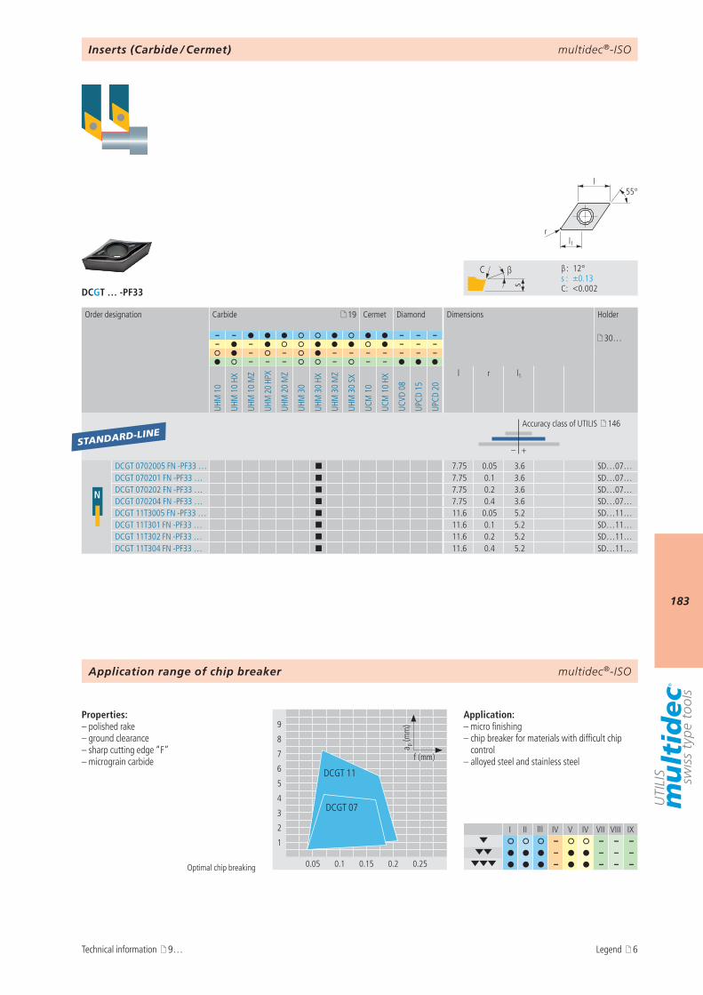
multidec®-ISO
183
DCGT … -PF33
I II III IV V IV VII VIII IX– – – –
– – – – – – – –
9
8
7
6
5
4
3
2
1
0.05 0.1 0.15 0.2 0.25
a p (m
m)
f (mm)
DCGT 11
DCGT 07
s
C β
β : 12° s : ±0.13 C : <0.002
l1r
55°l
19
– – – – – 30…– – – – –
– – – – – – – – –– – – – – –
UHM
10
UHM
10
HX
UHM
10
MZ
UHM
20
HPX
UHM
20
MZ
UHM
30
UHM
30
HX
UHM
30
MZ
UHM
30
SX
UCM
10
UCM
10
HX
UCVD
08
UPCD
15
UPCD
20
l r l1
– +
N
DCGT 0702005 FN -PF33 … ¢ 7.75 0.05 3.6 SD…07…DCGT 070201 FN -PF33 … ¢ 7.75 0.1 3.6 SD…07…DCGT 070202 FN -PF33 … ¢ 7.75 0.2 3.6 SD…07…DCGT 070204 FN -PF33 … ¢ 7.75 0.4 3.6 SD…07…DCGT 11T3005 FN -PF33 … ¢ 11.6 0.05 5.2 SD…11…DCGT 11T301 FN -PF33 … ¢ 11.6 0.1 5.2 SD…11…DCGT 11T302 FN -PF33 … ¢ 11.6 0.2 5.2 SD…11…DCGT 11T304 FN -PF33 … ¢ 11.6 0.4 5.2 SD…11…
STANDARD-LINE
multidec®-ISO
Optimal chip breaking
Properties:– polished rake – ground clearance– sharp cutting edge “F”– micrograin carbide
Application:– micro finishing– chip breaker for materials with difficult chip
control– alloyed steel and stainless steel
Order designation Carbide Cermet Diamond Dimensions Holder
Accuracy class of UTILIS 146
Inserts (Carbide / Cermet)
Application range of chip breaker
Technical information 9… Legend 6

multidec®-ISO
184
DCMT … -PF43
I II III IV V IV VII VIII IX– – – –
– – – – – – – – – – – – –
9
8
7
6
5
4
3
2
1
0.05 0.1 0.15 0.2 0.25
a p (m
m)
f (mm)
DCMT 11
DCMT 07
s
C β
β : 12° s : ±0.13 C : <0.02
l1r
55°l
19
– – – – – 30…– – – – –
– – – – – – – – –– – – – – –
UHM
10
UHM
10
HX
UHM
10
MZ
UHM
20
HPX
UHM
20
MZ
UHM
30
UHM
30
HX
UHM
30
MZ
UHM
30
SX
UCM
10
UCM
10
HX
UCVD
08
UPCD
15
UPCD
20
l r l1
– +
NDCMT 070202 EN -PF43 … ¢ ¢ 7.75 0.2 3.8 SD…07…DCMT 070204 EN -PF43 … ¢ 7.75 0.4 3.8 SD…07…DCMT 11T302 EN -PF43 … ¢ 11.6 0.2 5.5 SD…11…DCMT 11T304 EN -PF43 … ¢ 11.6 0.4 5.5 SD…11…DCMT 11T308 EN -PF43 … ¢ 11.6 0.8 5.5 SD…11…
VALUE-LINE
multidec®-ISO
Optimal chip breaking
Properties:– sintered insert based on ISO standard– rounded cutting edge “E”– micrograin carbide
Application:– roughing and finishing– chip breaker for materials with difficult chip
control– alloyed steel and stainless steel
Order designation Carbide Cermet Diamond Dimensions Holder
Accuracy class of UTILIS 146
Inserts (Carbide / Cermet)
Application range of chip breaker
Technical information 9… Legend 6
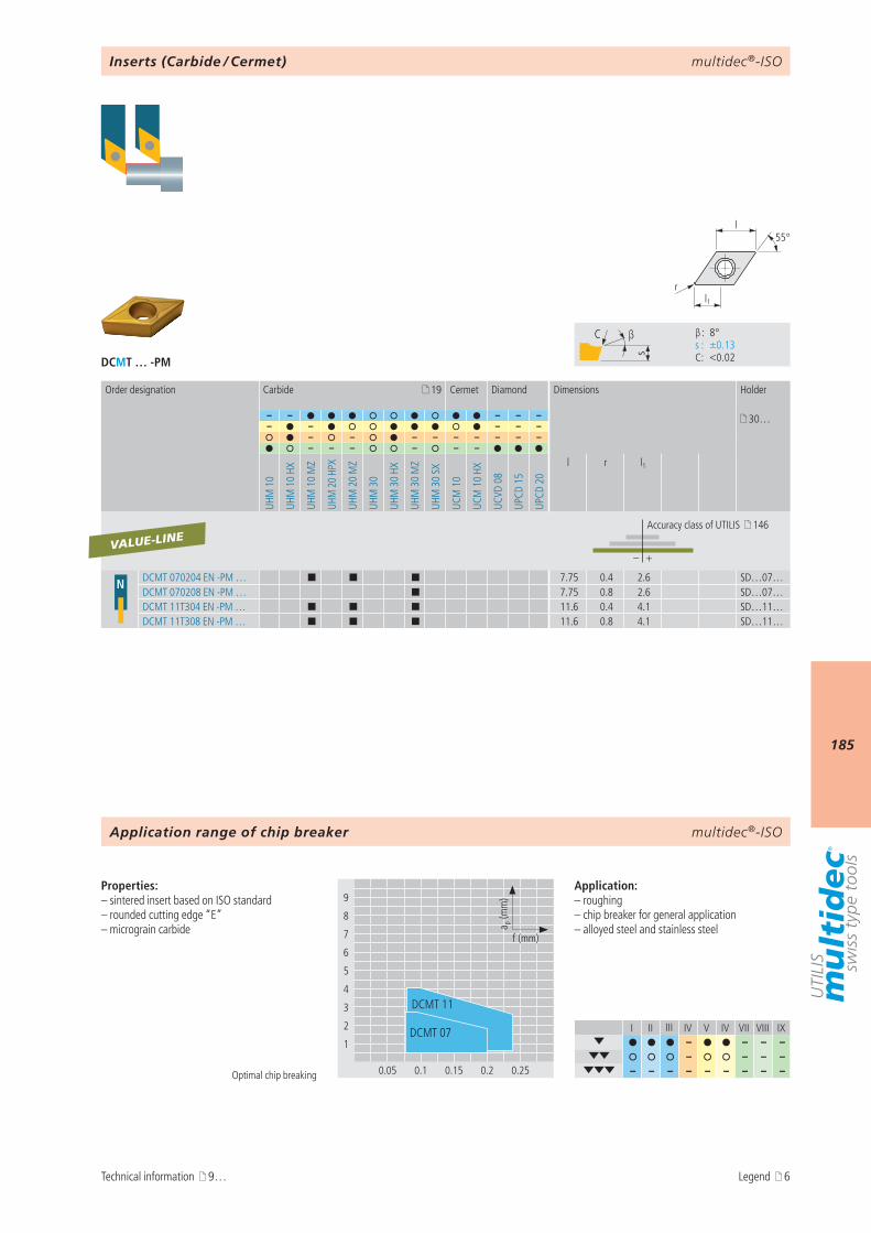
multidec®-ISO
185
DCMT … -PM
I II III IV V IV VII VIII IX– – – –
– – – – – – – – – – – – –
9
8
7
6
5
4
3
2
1
0.05 0.1 0.15 0.2 0.25
a p (m
m)
f (mm)
DCMT 11
DCMT 07
s
C β
β : 8° s : ±0.13 C : <0.02
l1r
55°l
19
– – – – – 30…– – – – –
– – – – – – – – –– – – – – –
UHM
10
UHM
10
HX
UHM
10
MZ
UHM
20
HPX
UHM
20
MZ
UHM
30
UHM
30
HX
UHM
30
MZ
UHM
30
SX
UCM
10
UCM
10
HX
UCVD
08
UPCD
15
UPCD
20
l r l1
– +
N DCMT 070204 EN -PM … ¢ ¢ ¢ 7.75 0.4 2.6 SD…07…DCMT 070208 EN -PM … ¢ 7.75 0.8 2.6 SD…07…DCMT 11T304 EN -PM … ¢ ¢ ¢ 11.6 0.4 4.1 SD…11…DCMT 11T308 EN -PM … ¢ ¢ ¢ 11.6 0.8 4.1 SD…11…
VALUE-LINE
multidec®-ISO
Optimal chip breaking
Properties:– sintered insert based on ISO standard– rounded cutting edge “E”– micrograin carbide
Application:– roughing– chip breaker for general application– alloyed steel and stainless steel
Order designation Carbide Cermet Diamond Dimensions Holder
Accuracy class of UTILIS 146
Inserts (Carbide / Cermet)
Application range of chip breaker
Technical information 9… Legend 6

multidec®-ISO
186
DCMT … -PMF
I II III IV V IV VII VIII IX– – – –
– – – – – – – – – – – – –
9
8
7
6
5
4
3
2
1
0.05 0.1 0.15 0.2 0.25
a p (m
m)
f (mm)
DCMT 11
DCMT 07
s
C β
β : 8° s : ±0.13 C : <0.02
l1r
55°l
19
– – – – – 30…– – – – –
– – – – – – – – – –– – – – – – –
UHM
10
UHM
10
HX
UHM
10
MZ
UHM
20
HPX
UHM
20
MZ
UHM
30
UHM
30
HX
UHM
30
MZ
UHM
30
SX
UCM
10
UCM
10
HX
UCM
10
MZ
UCVD
08
UPCD
15
UPCD
20
l r l1
– +
N DCMT 070202 EN -PMF ¢ 7.75 0.2 2.6 SD…07…DCMT 070204 EN -PMF ¢ 7.75 0.4 2.6 SD…07…DCMT 11T304 EN -PMF ¢ 11.6 0.4 4.1 SD…11…DCMT 11T308 EN -PMF ¢ 11.6 0.8 4.1 SD…11…
VALUE-LINE
multidec®-ISO
Optimal chip breaking
Properties:– sintered insert based on ISO standard– rounded cutting edge “E”– micrograin carbide
Application:– roughing and finishing– chip breaker for general application– alloyed steel and stainless steel
Inserts (Carbide / Cermet)
Order designation Carbide Cermet Diamond Dimensions Holder
Accuracy class of UTILIS 146
Application range of chip breaker
Technical information 9… Legend 6
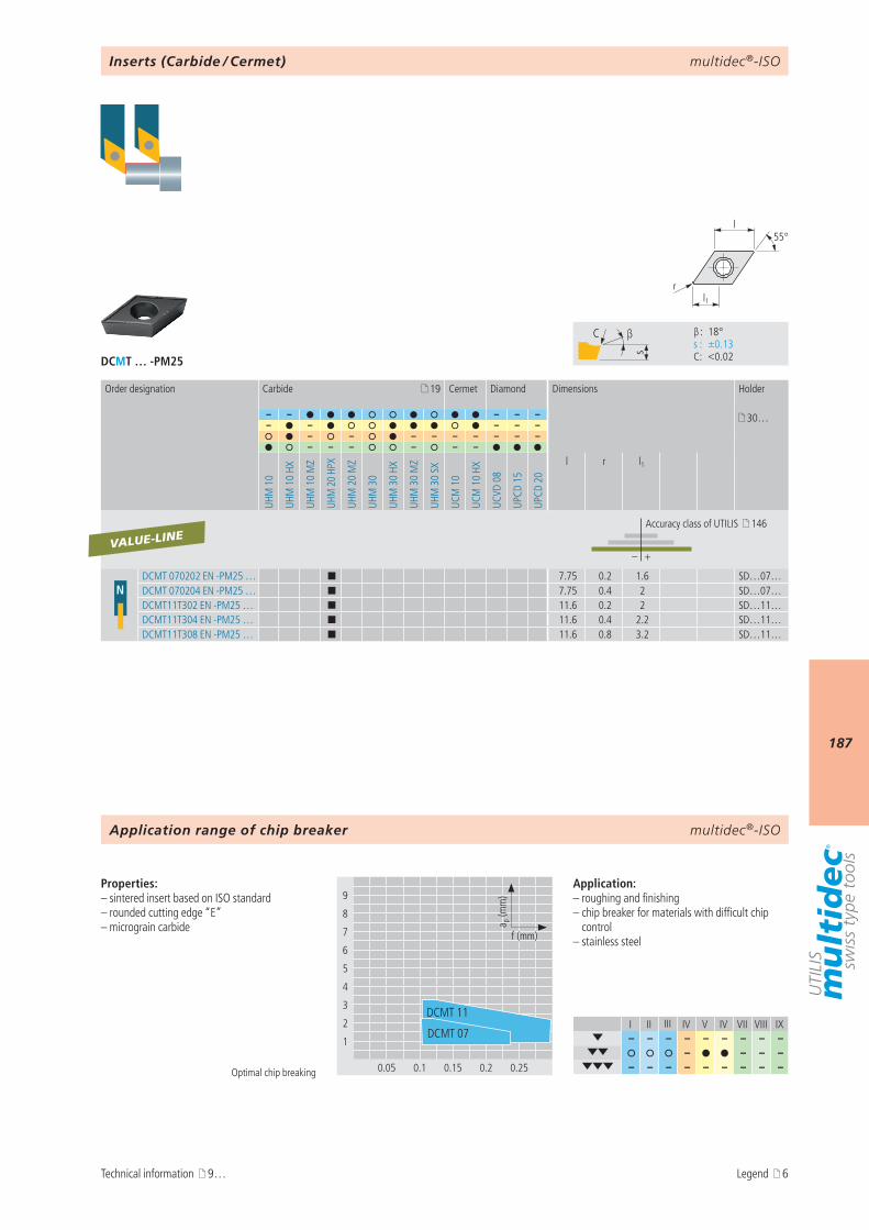
multidec®-ISO
187
DCMT … -PM25
I II III IV V IV VII VIII IX– – – – – – – – –
– – – – – – – – – – – – –
9
8
7
6
5
4
3
2
1
0.05 0.1 0.15 0.2 0.25
a p (m
m)
f (mm)
DCMT 11
DCMT 07
s
C β
β : 18° s : ±0.13 C : <0.02
l1r
55°l
19
– – – – – 30…– – – – –
– – – – – – – – –– – – – – –
UHM
10
UHM
10
HX
UHM
10
MZ
UHM
20
HPX
UHM
20
MZ
UHM
30
UHM
30
HX
UHM
30
MZ
UHM
30
SX
UCM
10
UCM
10
HX
UCVD
08
UPCD
15
UPCD
20
l r l1
– +
NDCMT 070202 EN -PM25 … ¢ 7.75 0.2 1.6 SD…07…DCMT 070204 EN -PM25 … ¢ 7.75 0.4 2 SD…07…DCMT11T302 EN -PM25 … ¢ 11.6 0.2 2 SD…11…DCMT11T304 EN -PM25 … ¢ 11.6 0.4 2.2 SD…11…DCMT11T308 EN -PM25 … ¢ 11.6 0.8 3.2 SD…11…
VALUE-LINE
multidec®-ISO
Optimal chip breaking
Properties:– sintered insert based on ISO standard– rounded cutting edge “E”– micrograin carbide
Application:– roughing and finishing– chip breaker for materials with difficult chip
control– stainless steel
Order designation Carbide Cermet Diamond Dimensions Holder
Accuracy class of UTILIS 146
Inserts (Carbide / Cermet)
Application range of chip breaker
Technical information 9… Legend 6
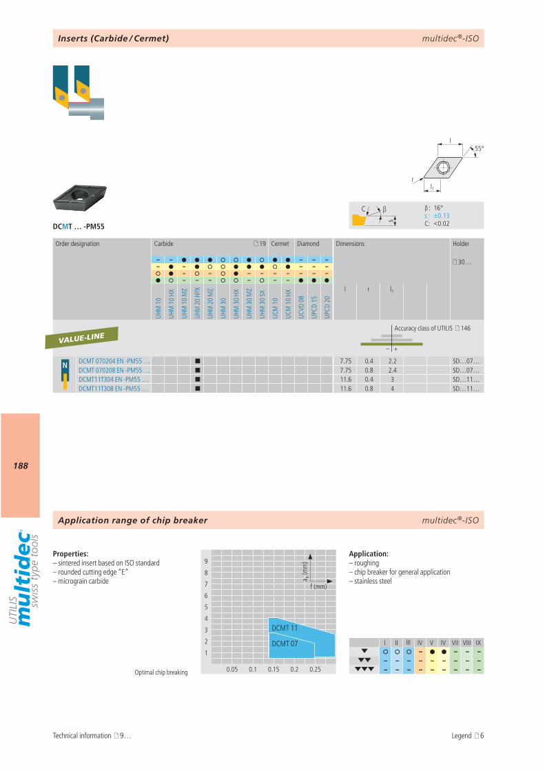
multidec®-ISO
188
DCMT … -PM55
I II III IV V IV VII VIII IX– – – –
– – – – – – – – – – – – – – – – – –
9
8
7
6
5
4
3
2
1
0.05 0.1 0.15 0.2 0.25
a p (m
m)
f (mm)
DCMT 11
DCMT 07
s
C β
β : 16° s : ±0.13 C : <0.02
l1r
55°l
19
– – – – – 30…– – – – –
– – – – – – – – –– – – – – –
UHM
10
UHM
10
HX
UHM
10
MZ
UHM
20
HPX
UHM
20
MZ
UHM
30
UHM
30
HX
UHM
30
MZ
UHM
30
SX
UCM
10
UCM
10
HX
UCVD
08
UPCD
15
UPCD
20
l r l1
– +
N DCMT 070204 EN -PM55 … ¢ 7.75 0.4 2.2 SD…07…DCMT 070208 EN -PM55 … ¢ 7.75 0.8 2.4 SD…07…DCMT11T304 EN -PM55 … ¢ 11.6 0.4 3 SD…11…DCMT11T308 EN -PM55 … ¢ 11.6 0.8 4 SD…11…
VALUE-LINE
multidec®-ISO
Optimal chip breaking
Properties:– sintered insert based on ISO standard– rounded cutting edge “E”– micrograin carbide
Application:– roughing– chip breaker for general application– stainless steel
Order designation Carbide Cermet Diamond Dimensions Holder
Accuracy class of UTILIS 146
Inserts (Carbide / Cermet)
Application range of chip breaker
Technical information 9… Legend 6
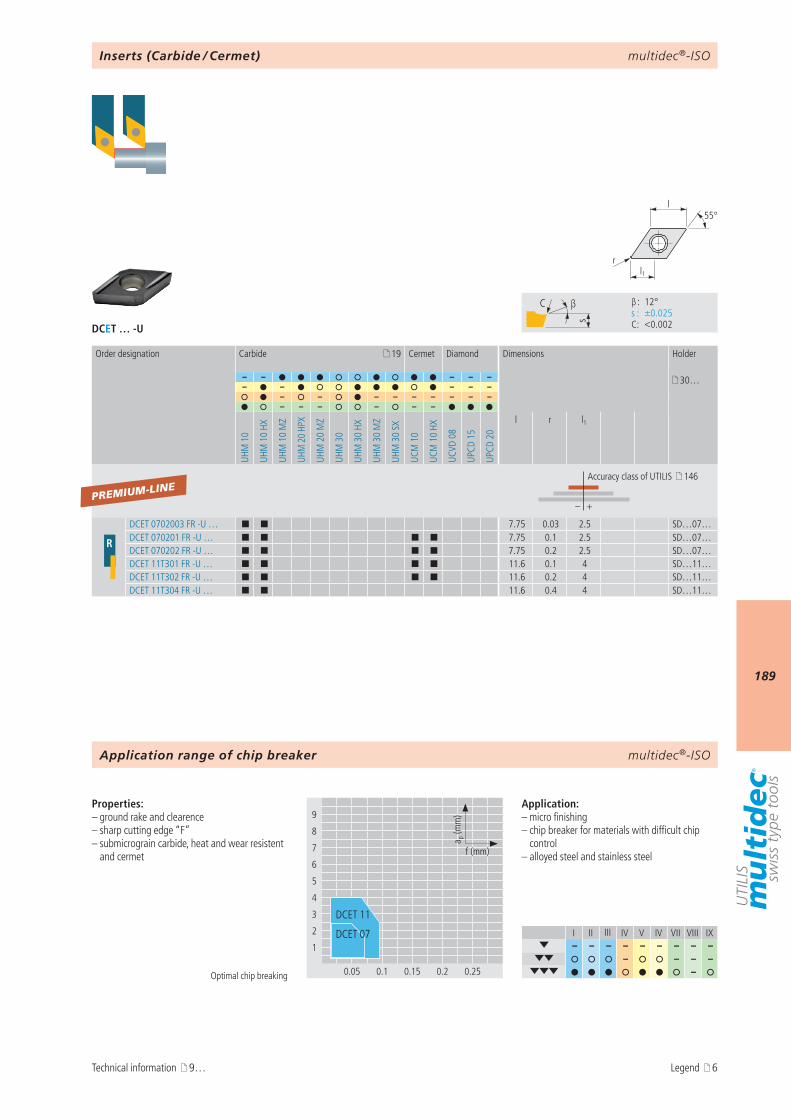
multidec®-ISO
189
DCET … -U
I II III IV V IV VII VIII IX– – – – – – – – –
– – – – –
9
8
7
6
5
4
3
2
1
0.05 0.1 0.15 0.2 0.25
a p (m
m)
f (mm)
DCET 07
DCET 11
s
C β
β : 12° s : ±0.025 C : <0.002
l1r
55°l
19
– – – – – 30…– – – – –
– – – – – – – – –– – – – – –
UHM
10
UHM
10
HX
UHM
10
MZ
UHM
20
HPX
UHM
20
MZ
UHM
30
UHM
30
HX
UHM
30
MZ
UHM
30
SX
UCM
10
UCM
10
HX
UCVD
08
UPCD
15
UPCD
20
l r l1
– +
R
DCET 0702003 FR -U … ¢ ¢ 7.75 0.03 2.5 SD…07…DCET 070201 FR -U … ¢ ¢ ¢ ¢ 7.75 0.1 2.5 SD…07…DCET 070202 FR -U … ¢ ¢ ¢ ¢ 7.75 0.2 2.5 SD…07…DCET 11T301 FR -U … ¢ ¢ ¢ ¢ 11.6 0.1 4 SD…11…DCET 11T302 FR -U … ¢ ¢ ¢ ¢ 11.6 0.2 4 SD…11…DCET 11T304 FR -U … ¢ ¢ 11.6 0.4 4 SD…11…
PREMIUM-LINE
multidec®-ISO
Optimal chip breaking
Properties:– ground rake and clearence– sharp cutting edge “F”– submicrograin carbide, heat and wear resistent
and cermet
Application:– micro finishing– chip breaker for materials with difficult chip
control– alloyed steel and stainless steel
Order designation Carbide Cermet Diamond Dimensions Holder
Accuracy class of UTILIS 146
Inserts (Carbide / Cermet)
Application range of chip breaker
Technical information 9… Legend 6
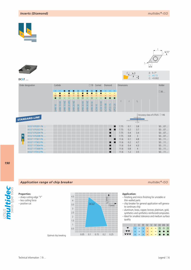
multidec®-ISO
190
DCGT …
I II III IV V IV VII VIII IX– – – – – –
– – – – – – – – – – – –
4.5
4
3.5
3
2.5
2
1.5
1
0.5
0.05 0.1 0.15 0.2 0.25
a p (m
m)
f (mm)DCGT
s
C β
β : 5–7° s : ±0.13 C : <0.002
l1r
55°l
19
– – – – – 30…– – – – –
– – – – – – – – –– – – – – –
UHM
10
UHM
10
HX
UHM
10
MZ
UHM
20
HPX
UHM
20
MZ
UHM
30
UHM
30
HX
UHM
30
MZ
UHM
30
SX
UCM
10
UCM
10
HX
UCVD
08
UPCD
15
UPCD
20
l r l1
– +
N
DCGT 070201 FN … ¢ 7.75 0.1 3.8 SD…07…DCGT 070202 FN … ¢ ¢ 7.75 0.2 3.7 SD…07…DCGT 070204 FN … ¢ 7.75 0.4 3.4 SD…07…DCGT 070208 FN … ¢ 7.75 0.8 3 SD…07…DCGT 11T301 FN … ¢ 11.6 0.1 4.8 SD…11…DCGT 11T302 FN … ¢ ¢ 11.6 0.2 4.7 SD…11…DCGT 11T304 FN … ¢ 11.6 0.4 4.3 SD…11…DCGT 11T308 FN … ¢ 11.6 0.8 4 SD…11…DCGT 11T312 FN … ¢ 11.6 1.2 3.5 SD…11…
STANDARD-LINE
multidec®-ISO
Optimal chip breaking
Properties:– sharp cutting edge “F”– less cutting force– positive cut
Application:– finishing and micro finishing for unstable or
thin-walled parts– chip breaker for general application will genera-
te continues chip– aluminum, brass, copper, bronze, platinium, gold,
synthetics and synthetics reinforced/composites– Ideal for smallest tolerance and medium surface
quality
Inserts (Diamond)
Order designation Carbide Cermet Diamond Dimensions Holder
Accuracy class of UTILIS 146
Application range of chip breaker
Technical information 9… Legend 6
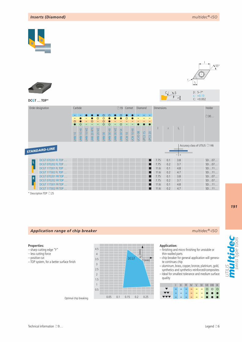
multidec®-ISO
191
DCGT … TOP*
I II III IV V IV VII VIII IX– – – – – –
– – – – – – – – – – – –
4.5
4
3.5
3
2.5
2
1.5
1
0.5
0.05 0.1 0.15 0.2 0.25
a p (m
m)
f (mm)DCGT
s
C β
β : 5–7° s : ±0.13 C : <0.002
l1r
55°l
19
– – – – – 30…– – – – –
– – – – – – – – –– – – – – –
UHM
10
UHM
10
HX
UHM
10
MZ
UHM
20
HPX
UHM
20
MZ
UHM
30
UHM
30
HX
UHM
30
MZ
UHM
30
SX
UCM
10
UCM
10
HX
UCVD
08
UPCD
15
UPCD
20
l r l1
– +
L DCGT 070201 FL TOP … ¢ 7.75 0.1 3.8 SD…07…DCGT 070202 FL TOP … ¢ 7.75 0.2 3.7 SD…07…DCGT 11T301 FL TOP … ¢ 11.6 0.1 4.8 SD…11…DCGT 11T302 FL TOP … ¢ 11.6 0.2 4.7 SD…11…
R DCGT 070201 FR TOP … ¢ 7.75 0.1 3.8 SD…07…DCGT 070202 FR TOP … ¢ 7.75 0.2 3.7 SD…07…DCGT 11T301 FR TOP … ¢ 11.6 0.1 4.8 SD…11…DCGT 11T302 FR TOP … ¢ 11.6 0.2 4.7 SD…11…
STANDARD-LINE
multidec®-ISO
Optimal chip breaking
Properties:– sharp cutting edge “F”– less cutting force– positive cut– TOP system, for a better surface finish
Application:– finishing and micro finishing for unstable or
thin-walled parts– chip breaker for general application will genera-
te continues chip– aluminum, brass, copper, bronze, platinium, gold,
synthetics and synthetics reinforced/composites– Ideal for smallest tolerance and medium surface
quality
Inserts (Diamond)
Order designation Carbide Cermet Diamond Dimensions Holder
Accuracy class of UTILIS 146
Application range of chip breaker
Technical information 9…
* Description TOP 25
Legend 6
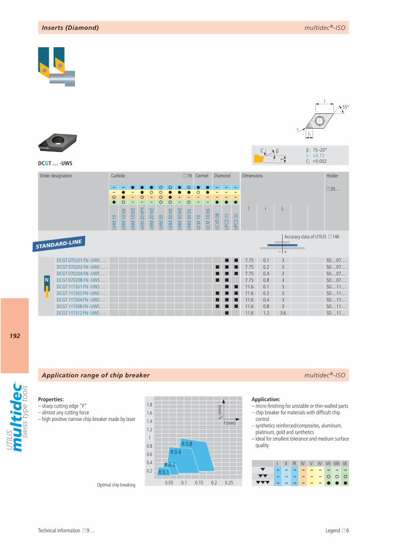
multidec®-ISO
192
I II III IV V IV VII VIII IX– – – – – – – – –
– – – – – – – – – – – –
DCGT … -UWS
s
C β
β : 15–20° s : ±0.13 C : <0.002
1.8
1.6
1.4
1.2
1
0.8
0.6
0.4
0.2
0.05 0.1 0.15 0.2 0.25
a p (m
m)
f (mm)
R 0.4
R 0.1
R 0.8
R 0.2
l1r
55°l
19
– – – – – 30…– – – – –
– – – – – – – – –– – – – – –
UHM
10
UHM
10
HX
UHM
10
MZ
UHM
20
HPX
UHM
20
MZ
UHM
30
UHM
30
HX
UHM
30
MZ
UHM
30
SX
UCM
10
UCM
10
HX
UCVD
08
UPCD
15
UPCD
20
l r l1
– +
N
DCGT 070201 FN -UWS … ¢ ¢ 7.75 0.1 3 SD…07…DCGT 070202 FN -UWS … ¢ ¢ ¢ 7.75 0.2 3 SD…07…DCGT 070204 FN -UWS … ¢ ¢ ¢ 7.75 0.4 3 SD…07…DCGT 070208 FN -UWS … ¢ ¢ 7.75 0.8 3 SD…07…DCGT 11T301 FN -UWS … ¢ ¢ 11.6 0.1 3 SD…11…DCGT 11T302 FN -UWS … ¢ ¢ ¢ 11.6 0.2 3 SD…11…DCGT 11T304 FN -UWS … ¢ ¢ ¢ 11.6 0.4 3 SD…11…DCGT 11T308 FN -UWS … ¢ ¢ ¢ 11.6 0.8 3 SD…11…DCGT 11T312 FN -UWS … ¢ 11.6 1.2 3.6 SD…11…
STANDARD-LINE
multidec®-ISO
Optimal chip breaking
Properties:– sharp cutting edge “F”– almost any cutting force– high positive narrow chip breaker made by laser
Application:– micro finishing for unstable or thin-walled parts– chip breaker for materials with difficult chip
control– synthetics reinforced/composites, aluminum,
platinium, gold and synthetics– Ideal for smallest tolerance and medium surface
quality
Inserts (Diamond)
Order designation Carbide Cermet Diamond Dimensions Holder
Accuracy class of UTILIS 146
Application range of chip breaker
Technical information 9… Legend 6
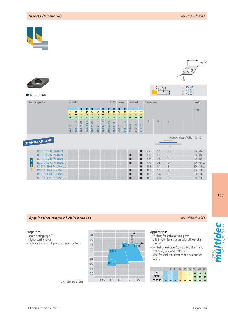
multidec®-ISO
193
I II III IV V IV VII VIII IX– – – – – –
– – – – – – – – – – – – – – –
DCGT … -UWN
s
C β
β : 15–20° s : ±0.13 C : <0.005
1.8
1.6
1.4
1.2
1
0.8
0.6
0.4
0.2
0.05 0.1 0.15 0.2 0.25
R 0.4
R 0.8
R 0.2
a p (m
m)
f (mm)
l1r
55°l
19
– – – – – 30…– – – – –
– – – – – – – – –– – – – – –
UHM
10
UHM
10
HX
UHM
10
MZ
UHM
20
HPX
UHM
20
MZ
UHM
30
UHM
30
HX
UHM
30
MZ
UHM
30
SX
UCM
10
UCM
10
HX
UCVD
08
UPCD
15
UPCD
20
l r l1
– +
N
DCGT 070201 FN -UWN … ¢ 7.75 0.1 3 SD…07…DCGT 070202 FN -UWN … ¢ ¢ 7.75 0.2 3 SD…07…DCGT 070204 FN -UWN … ¢ ¢ 7.75 0.4 3 SD…07…DCGT 070208 FN -UWN … ¢ ¢ 7.75 0.8 3 SD…07…DCGT 11T301 FN -UWN … ¢ 11.6 0.1 3 SD…11…DCGT 11T302 FN -UWN … ¢ ¢ 11.6 0.2 3 SD…11…DCGT 11T304 FN -UWN … ¢ ¢ 11.6 0.4 3 SD…11…DCGT 11T308 FN -UWN … ¢ ¢ 11.6 0.8 3 SD…11…
STANDARD-LINE
multidec®-ISO
Optimal chip breaking
Properties:– sharp cutting edge “F”– higher cutting force– high positive wide chip breaker made by laser
Application:– finishing for stable or solid parts– chip breaker for materials with difficult chip
control– synthetics reinforced/composites, aluminum,
platinium, gold and synthetics– Ideal for smallest tolerance and best surface
quality
Inserts (Diamond)
Order designation Carbide Cermet Diamond Dimensions Holder
Accuracy class of UTILIS 146
Application range of chip breaker
Technical information 9… Legend 6

multidec®-ISO
194
I II III IV V IV VII VIII IX– – – – – –
– – – – – – – – – – – – – – –
DCGT … -UWR
s
C β
β : 15–20° s : ±0.13 C : <0.005
l1r
55°l
19
– – – – – 30…– – – – –
– – – – – – – – –– – – – – –
UHM
10
UHM
10
HX
UHM
10
MZ
UHM
20
HPX
UHM
20
MZ
UHM
30
UHM
30
HX
UHM
30
MZ
UHM
30
SX
UCM
10
UCM
10
HX
UCVD
08
UPCD
15
UPCD
20
l r l1
– +
N DCGT 070204 FN -UWR … ¢ 7.75 0.4 3 SD…07…DCGT 11T304 FN -UWR … ¢ 11.6 0.4 3 SD…11…DCGT 11T308 FN -UWR … ¢ 11.6 0.8 3 SD…11…
STANDARD-LINE
3.6
3.2
2.8
2.4
2
1.6
1.2
0.8
0.4
0.1 0.2 0.3 0.4 0.5
a p (m
m)
f (mm)
multidec®-ISO
Optimal chip breaking
Properties:– sharp cutting edge “F”– higher cutting force– high positive wide chip breaker made by laser
Application:– machining of massive or solid parts– chip breaker for materials with difficult chip
control– synthetics reinforced/composites, aluminum,
platinium, gold and synthetics– maximum metal removal rate
Inserts (Diamond)
Order designation Carbide Cermet Diamond Dimensions Holder
Accuracy class of UTILIS 146
Application range of chip breaker
Technical information 9… Legend 6
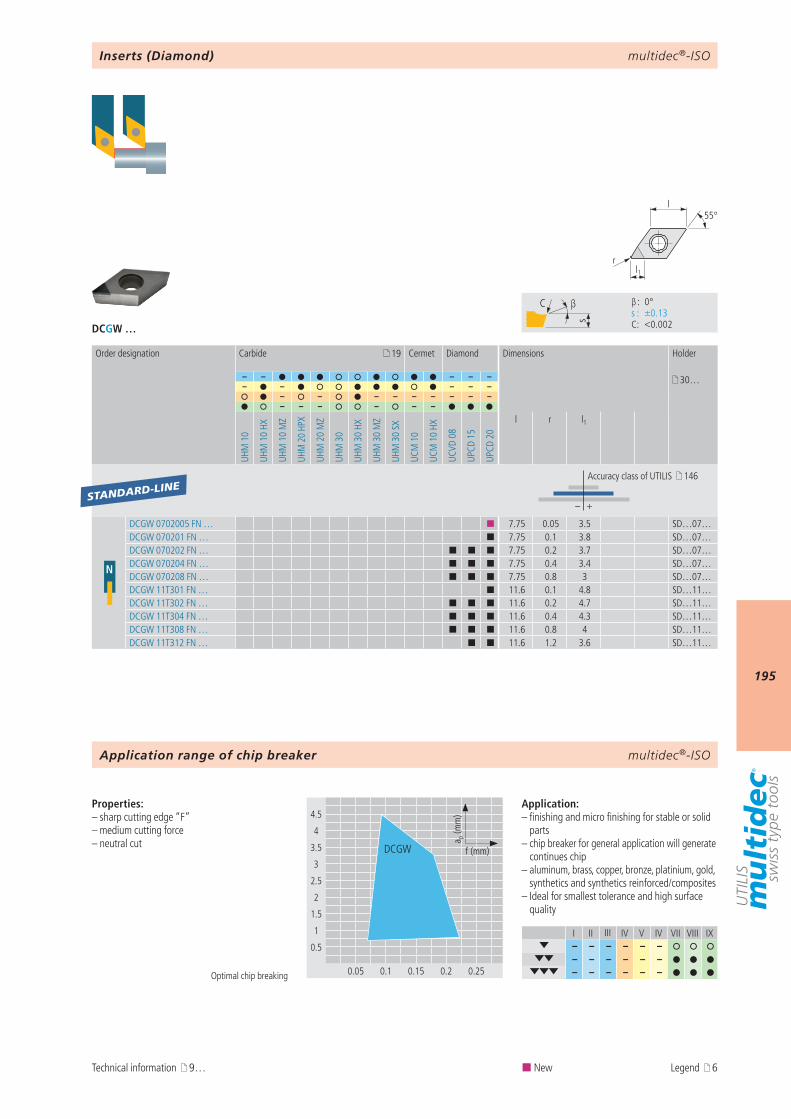
multidec®-ISO
195
DCGW …
I II III IV V IV VII VIII IX– – – – – –
– – – – – – – – – – – –
4.5
4
3.5
3
2.5
2
1.5
1
0.5
0.05 0.1 0.15 0.2 0.25
a p (m
m)
f (mm)DCGW
s
C β
β : 0° s : ±0.13 C : <0.002
l1r
55°l
19
– – – – – 30…– – – – –
– – – – – – – – –– – – – – –
UHM
10
UHM
10
HX
UHM
10
MZ
UHM
20
HPX
UHM
20
MZ
UHM
30
UHM
30
HX
UHM
30
MZ
UHM
30
SX
UCM
10
UCM
10
HX
UCVD
08
UPCD
15
UPCD
20
l r l1
– +
N
DCGW 0702005 FN … ¢ 7.75 0.05 3.5 SD…07…DCGW 070201 FN … ¢ 7.75 0.1 3.8 SD…07…DCGW 070202 FN … ¢ ¢ ¢ 7.75 0.2 3.7 SD…07…DCGW 070204 FN … ¢ ¢ ¢ 7.75 0.4 3.4 SD…07…DCGW 070208 FN … ¢ ¢ ¢ 7.75 0.8 3 SD…07…DCGW 11T301 FN … ¢ 11.6 0.1 4.8 SD…11…DCGW 11T302 FN … ¢ ¢ ¢ 11.6 0.2 4.7 SD…11…DCGW 11T304 FN … ¢ ¢ ¢ 11.6 0.4 4.3 SD…11…DCGW 11T308 FN … ¢ ¢ ¢ 11.6 0.8 4 SD…11…DCGW 11T312 FN … ¢ ¢ 11.6 1.2 3.6 SD…11…
STANDARD-LINE
multidec®-ISO
Optimal chip breaking
Properties:– sharp cutting edge “F”– medium cutting force– neutral cut
Application:– finishing and micro finishing for stable or solid
parts– chip breaker for general application will generate
continues chip– aluminum, brass, copper, bronze, platinium, gold,
synthetics and synthetics reinforced/composites– Ideal for smallest tolerance and high surface
quality
Inserts (Diamond)
Order designation Carbide Cermet Diamond Dimensions Holder
Accuracy class of UTILIS 146
Application range of chip breaker
Technical information 9… ¢ New Legend 6
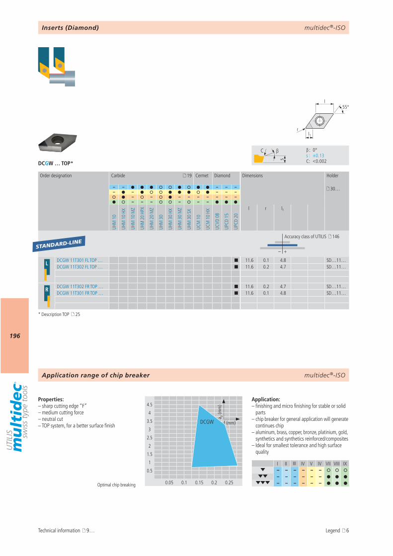
multidec®-ISO
196
DCGW … TOP*
I II III IV V IV VII VIII IX– – – – – –
– – – – – – – – – – – –
4.5
4
3.5
3
2.5
2
1.5
1
0.5
0.05 0.1 0.15 0.2 0.25
a p (m
m)
f (mm)DCGW
s
C β
β : 0° s : ±0.13 C : <0.002
l1r
55°l
19
– – – – – 30…– – – – –
– – – – – – – – –– – – – – –
UHM
10
UHM
10
HX
UHM
10
MZ
UHM
20
HPX
UHM
20
MZ
UHM
30
UHM
30
HX
UHM
30
MZ
UHM
30
SX
UCM
10
UCM
10
HX
UCVD
08
UPCD
15
UPCD
20
l r l1
– +
L DCGW 11T301 FL TOP … ¢ 11.6 0.1 4.8 SD…11…DCGW 11T302 FL TOP … ¢ 11.6 0.2 4.7 SD…11…
R DCGW 11T302 FR TOP … ¢ 11.6 0.2 4.7 SD…11…DCGW 11T301 FR TOP … ¢ 11.6 0.1 4.8 SD…11…
STANDARD-LINE
multidec®-ISO
Optimal chip breaking
Properties:– sharp cutting edge “F”– medium cutting force– neutral cut– TOP system, for a better surface finish
Application:– finishing and micro finishing for stable or solid
parts– chip breaker for general application will generate
continues chip– aluminum, brass, copper, bronze, platinium, gold,
synthetics and synthetics reinforced/composites– Ideal for smallest tolerance and high surface
quality
Inserts (Diamond)
Order designation Carbide Cermet Diamond Dimensions Holder
Accuracy class of UTILIS 146
Application range of chip breaker
Technical information 9…
* Description TOP 25
Legend 6

multidec®-ISO
197
AttentionPlease note the legend 6…
Notes
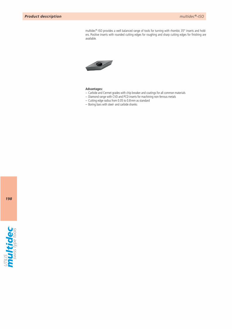
multidec®-ISO
198
Product description
multidec®-ISO provides a well balanced range of tools for turning with rhombic 35° inserts and hold-ers. Positive inserts with rounded cutting edges for roughing and sharp cutting edges for finishing are available.
Advantages:– Carbide and Cermet grades with chip breaker and coatings for all common materials– Diamond range with CVD and PCD inserts for machining non-ferrous metals– Cutting edge radius from 0.05 to 0.8 mm as standard– Boring bars with steel- and carbide shanks
multidec®-ISO
199
9 VCGT … -A3 200VCGT … -PA5 201VCGT … -TOP5 202VCGT … -PA7 203VCXT … -PA9 204VCGT … -PF 205VCMT … -PF 206VCGT … -PF23 207VCGT … -PF33 208VCMT … -PF43 209VCMT … -PM 210VCMT … -PMF 211VCMT … -PM25 212VCMT … -PM55 213
VCGT … 214VCGT … -UWS, VCGT … -UWN, VCGT … -UWR 215VCGW … 218
multidec®-ISOOverview type VC… (35°)
Technical information Inserts (carbide / cermet)
Inserts (diamond)
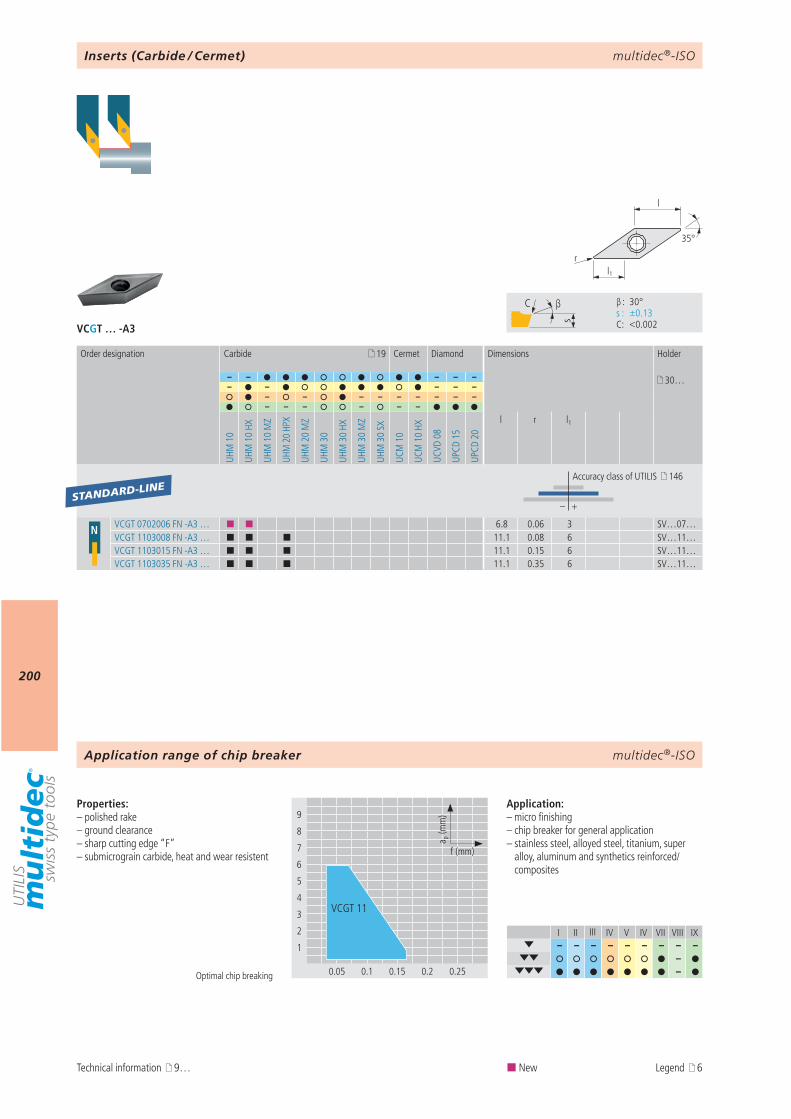
multidec®-ISO
200
VCGT … -A3
I II III IV V IV VII VIII IX– – – – – – – – –
– –
9
8
7
6
5
4
3
2
1
0.05 0.1 0.15 0.2 0.25
a p (m
m)
f (mm)
VCGT 11
s
C β
β : 30° s : ±0.13 C : <0.002
l1r
35°
l
19
– – – – – 30…– – – – –
– – – – – – – – –– – – – – –
UHM
10
UHM
10
HX
UHM
10
MZ
UHM
20
HPX
UHM
20
MZ
UHM
30
UHM
30
HX
UHM
30
MZ
UHM
30
SX
UCM
10
UCM
10
HX
UCVD
08
UPCD
15
UPCD
20
l r l1
– +
N VCGT 0702006 FN -A3 … ¢ ¢ 6.8 0.06 3 SV…07…VCGT 1103008 FN -A3 … ¢ ¢ ¢ 11.1 0.08 6 SV…11…VCGT 1103015 FN -A3 … ¢ ¢ ¢ 11.1 0.15 6 SV…11…VCGT 1103035 FN -A3 … ¢ ¢ ¢ 11.1 0.35 6 SV…11…
STANDARD-LINE
multidec®-ISO
Optimal chip breaking
Properties:– polished rake – ground clearance– sharp cutting edge “F”– submicrograin carbide, heat and wear resistent
Application:– micro finishing– chip breaker for general application– stainless steel, alloyed steel, titanium, super
alloy, aluminum and synthetics reinforced/composites
Inserts (Carbide / Cermet)
Order designation Carbide Cermet Diamond Dimensions Holder
Accuracy class of UTILIS 146
Application range of chip breaker
Technical information 9… ¢ New Legend 6
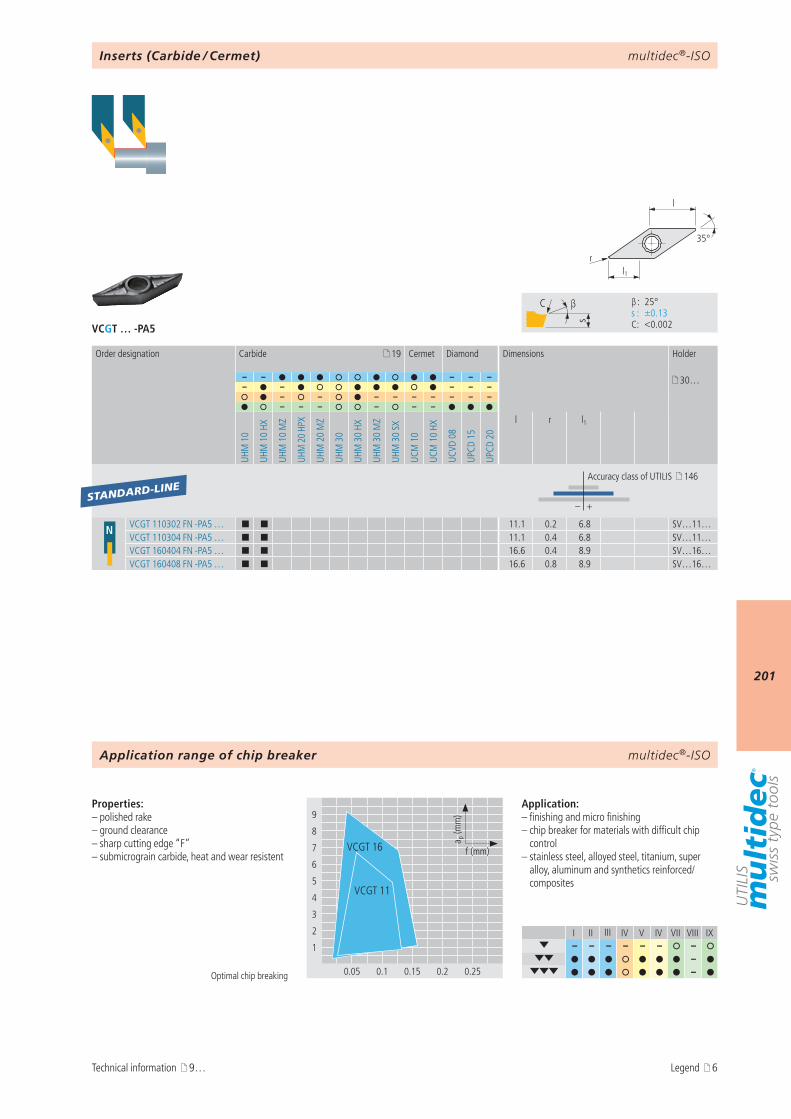
multidec®-ISO
201
VCGT … -PA5
I II III IV V IV VII VIII IX– – – – – – –
– –
9
8
7
6
5
4
3
2
1
0.05 0.1 0.15 0.2 0.25
a p (m
m)
f (mm)VCGT 16
VCGT 11
s
C β
β : 25° s : ±0.13 C : <0.002
l1r
35°
l
19
– – – – – 30…– – – – –
– – – – – – – – –– – – – – –
UHM
10
UHM
10
HX
UHM
10
MZ
UHM
20
HPX
UHM
20
MZ
UHM
30
UHM
30
HX
UHM
30
MZ
UHM
30
SX
UCM
10
UCM
10
HX
UCVD
08
UPCD
15
UPCD
20
l r l1
– +
N VCGT 110302 FN -PA5 … ¢ ¢ 11.1 0.2 6.8 SV…11…VCGT 110304 FN -PA5 … ¢ ¢ 11.1 0.4 6.8 SV…11…VCGT 160404 FN -PA5 … ¢ ¢ 16.6 0.4 8.9 SV…16…VCGT 160408 FN -PA5 … ¢ ¢ 16.6 0.8 8.9 SV…16…
STANDARD-LINE
multidec®-ISO
Optimal chip breaking
Properties:– polished rake – ground clearance– sharp cutting edge “F”– submicrograin carbide, heat and wear resistent
Application:– finishing and micro finishing– chip breaker for materials with difficult chip
control– stainless steel, alloyed steel, titanium, super
alloy, aluminum and synthetics reinforced/composites
Inserts (Carbide / Cermet)
Order designation Carbide Cermet Diamond Dimensions Holder
Accuracy class of UTILIS 146
Application range of chip breaker
Technical information 9… Legend 6
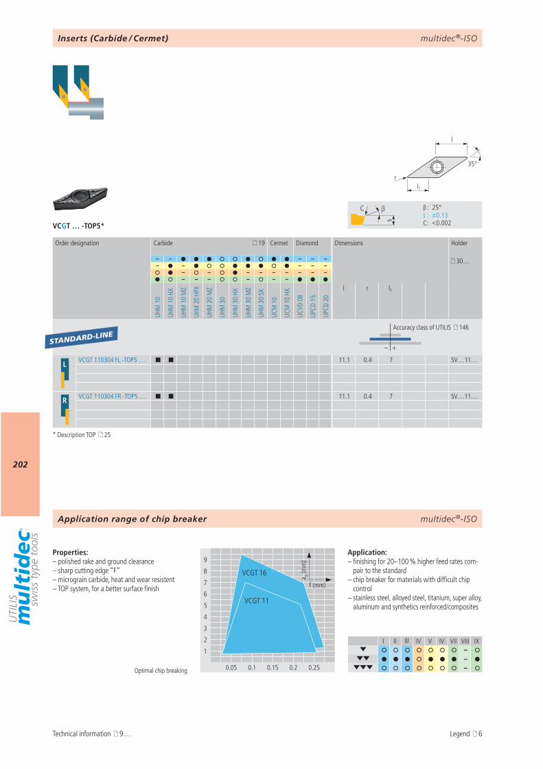
multidec®-ISO
202
VCGT … -TOP5*
I II III IV V IV VII VIII IX–
– –
9
8
7
6
5
4
3
2
1
0.05 0.1 0.15 0.2 0.25
a p (m
m)
f (mm)
VCGT 16
VCGT 11
s
C β
β : 25° s : ±0.13 C : <0.002
l1r
35°
l
19
– – – – – 30…– – – – –
– – – – – – – – –– – – – – –
UHM
10
UHM
10
HX
UHM
10
MZ
UHM
20
HPX
UHM
20
MZ
UHM
30
UHM
30
HX
UHM
30
MZ
UHM
30
SX
UCM
10
UCM
10
HX
UCVD
08
UPCD
15
UPCD
20
l r l1
– +
L VCGT 110304 FL -TOP5 … ¢ ¢ 11.1 0.4 7 SV…11…
R VCGT 110304 FR -TOP5 … ¢ ¢ 11.1 0.4 7 SV…11…
STANDARD-LINE
multidec®-ISO
Optimal chip breaking
Properties:– polished rake and ground clearance– sharp cutting edge “F”– micrograin carbide, heat and wear resistent– TOP system, for a better surface finish
Application:– finishing for 20–100 % higher feed rates com-
pair to the standard– chip breaker for materials with difficult chip
control– stainless steel, alloyed steel, titanium, super alloy,
aluminum and synthetics reinforced/composites
Inserts (Carbide / Cermet)
Order designation Carbide Cermet Diamond Dimensions Holder
Accuracy class of UTILIS 146
Application range of chip breaker
Technical information 9…
* Description TOP 25
Legend 6
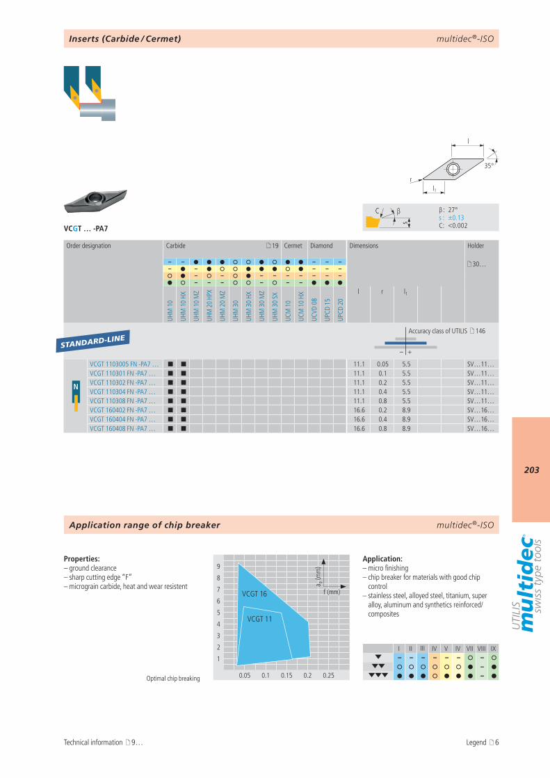
multidec®-ISO
203
VCGT … -PA7
I II III IV V IV VII VIII IX– – – – – – –
– –
9
8
7
6
5
4
3
2
1
0.05 0.1 0.15 0.2 0.25
a p (m
m)
f (mm)VCGT 16
VCGT 11
s
C β
β : 27° s : ±0.13 C : <0.002
l1r
35°
l
19
– – – – – 30…– – – – –
– – – – – – – – –– – – – – –
UHM
10
UHM
10
HX
UHM
10
MZ
UHM
20
HPX
UHM
20
MZ
UHM
30
UHM
30
HX
UHM
30
MZ
UHM
30
SX
UCM
10
UCM
10
HX
UCVD
08
UPCD
15
UPCD
20
l r l1
– +
N
VCGT 1103005 FN -PA7 … ¢ ¢ 11.1 0.05 5.5 SV…11…VCGT 110301 FN -PA7 … ¢ ¢ 11.1 0.1 5.5 SV…11…VCGT 110302 FN -PA7 … ¢ ¢ 11.1 0.2 5.5 SV…11…VCGT 110304 FN -PA7 … ¢ ¢ 11.1 0.4 5.5 SV…11…VCGT 110308 FN -PA7 … ¢ ¢ 11.1 0.8 5.5 SV…11…VCGT 160402 FN -PA7 … ¢ ¢ 16.6 0.2 8.9 SV…16…VCGT 160404 FN -PA7 … ¢ ¢ 16.6 0.4 8.9 SV…16…VCGT 160408 FN -PA7 … ¢ ¢ 16.6 0.8 8.9 SV…16…
STANDARD-LINE
multidec®-ISO
Optimal chip breaking
Properties:– ground clearance– sharp cutting edge “F”– micrograin carbide, heat and wear resistent
Application:– micro finishing– chip breaker for materials with good chip
control– stainless steel, alloyed steel, titanium, super
alloy, aluminum and synthetics reinforced/composites
Inserts (Carbide / Cermet)
Order designation Carbide Cermet Diamond Dimensions Holder
Accuracy class of UTILIS 146
Application range of chip breaker
Technical information 9… Legend 6
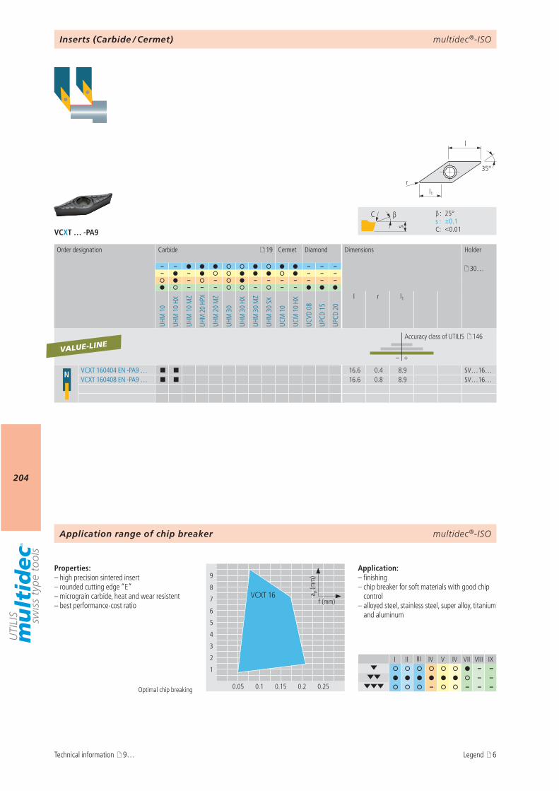
multidec®-ISO
204
VCXT … -PA9
I II III IV V IV VII VIII IX– –
– – – – – –
9
8
7
6
5
4
3
2
1
0.05 0.1 0.15 0.2 0.25
a p (m
m)
f (mm)VCXT 16
s
C β
β : 25° s : ±0.1 C : <0.01
l1r
35°
l
19
– – – – – 30…– – – – –
– – – – – – – – –– – – – – –
UHM
10
UHM
10
HX
UHM
10
MZ
UHM
20
HPX
UHM
20
MZ
UHM
30
UHM
30
HX
UHM
30
MZ
UHM
30
SX
UCM
10
UCM
10
HX
UCVD
08
UPCD
15
UPCD
20
l r l1
– +
N VCXT 160404 EN -PA9 … ¢ ¢ 16.6 0.4 8.9 SV…16…VCXT 160408 EN -PA9 … ¢ ¢ 16.6 0.8 8.9 SV…16…
VALUE-LINE
multidec®-ISO
Optimal chip breaking
Properties:– high precision sintered insert– rounded cutting edge “E”– micrograin carbide, heat and wear resistent– best performance-cost ratio
Application:– finishing– chip breaker for soft materials with good chip
control– alloyed steel, stainless steel, super alloy, titanium
and aluminum
Inserts (Carbide / Cermet)
Order designation Carbide Cermet Diamond Dimensions Holder
Accuracy class of UTILIS 146
Application range of chip breaker
Technical information 9… Legend 6
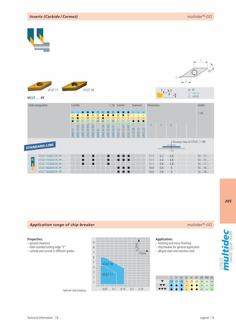
multidec®-ISO
205
VCGT … -PF
I II III IV V IV VII VIII IX– – – –
– – – – – – – –
VCGT 16VCGT 11
9
8
7
6
5
4
3
2
1
0.05 0.1 0.15 0.2 0.25
a p (m
m)
f (mm)
VCGT 16
VCGT 11
s
C β
β : 8° s : ±0.13 C : <0.01
l1r
35°
l
19
– – – – – 30…– – – – –
– – – – – – – – – –– – – – – – –
UHM
10
UHM
10
HX
UHM
10
MZ
UHM
20
HPX
UHM
20
MZ
UHM
30
UHM
30
HX
UHM
30
MZ
UHM
30
SX
UCM
10
UCM
10
HX
UCM
10
MZ
UCVD
08
UPCD
15
UPCD
20
l r l1
– +
NVCGT 110302 EN -PF … ¢ ¢ ¢ ¢ ¢ ¢ 11.1 0.2 4.8 SV…11…VCGT 110304 EN -PF … ¢ ¢ ¢ ¢ ¢ ¢ 11.1 0.4 4.8 SV…11…VCGT 110308 EN -PF … ¢ ¢ ¢ 11.1 0.8 4.8 SV…11…VCGT 160404 EN -PF … ¢ ¢ ¢ 16.6 0.4 6 SV…16…VCGT 160408 EN -PF … ¢ ¢ ¢ 16.6 0.8 6 SV…16…
STANDARD-LINE
multidec®-ISO
Optimal chip breaking
Properties:– ground clearance– little rounded cutting edge “E”– carbide and cermet in different grades
Application:– finishing and micro finishing– chip breaker for general application– alloyed steel and stainless steel
Inserts (Carbide / Cermet)
Order designation Carbide Cermet Diamond Dimensions Holder
Accuracy class of UTILIS 146
Application range of chip breaker
Technical information 9… Legend 6
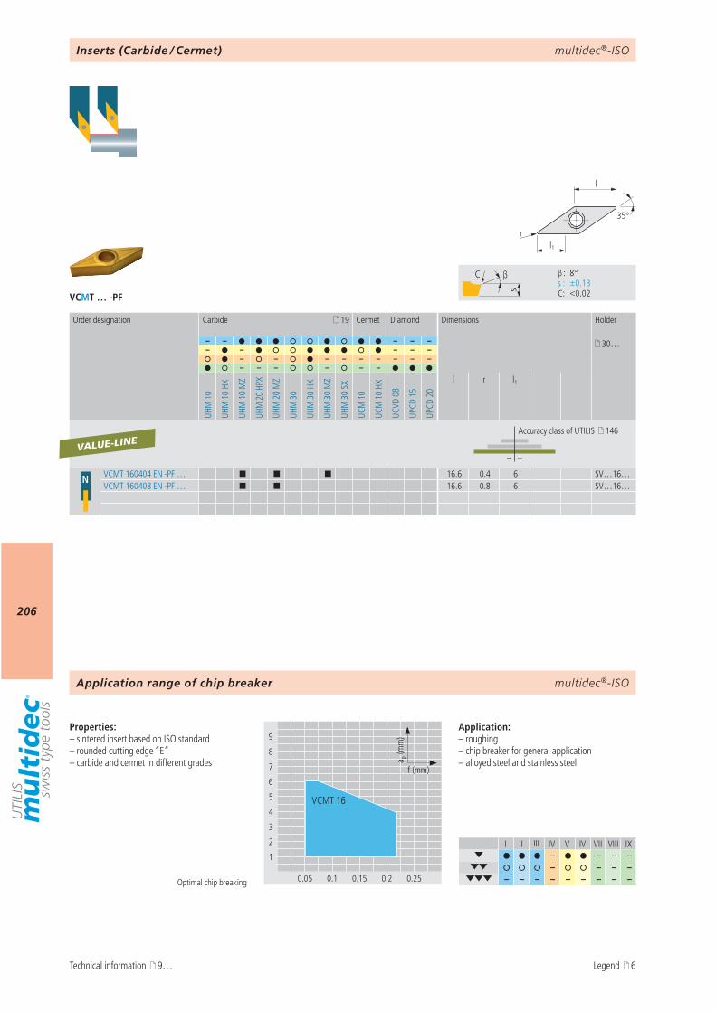
multidec®-ISO
206
VCMT … -PF
I II III IV V IV VII VIII IX– – – –
– – – – – – – – – – – – –
9
8
7
6
5
4
3
2
1
0.05 0.1 0.15 0.2 0.25
a p (m
m)
f (mm)
VCMT 16
s
C β
β : 8° s : ±0.13 C : <0.02
l1r
35°
l
19
– – – – – 30…– – – – –
– – – – – – – – –– – – – – –
UHM
10
UHM
10
HX
UHM
10
MZ
UHM
20
HPX
UHM
20
MZ
UHM
30
UHM
30
HX
UHM
30
MZ
UHM
30
SX
UCM
10
UCM
10
HX
UCVD
08
UPCD
15
UPCD
20
l r l1
– +
N VCMT 160404 EN -PF … ¢ ¢ ¢ 16.6 0.4 6 SV…16…VCMT 160408 EN -PF … ¢ ¢ 16.6 0.8 6 SV…16…
VALUE-LINE
multidec®-ISO
Optimal chip breaking
Properties:– sintered insert based on ISO standard– rounded cutting edge “E”– carbide and cermet in different grades
Application:– roughing– chip breaker for general application– alloyed steel and stainless steel
Inserts (Carbide / Cermet)
Order designation Carbide Cermet Diamond Dimensions Holder
Accuracy class of UTILIS 146
Application range of chip breaker
Technical information 9… Legend 6
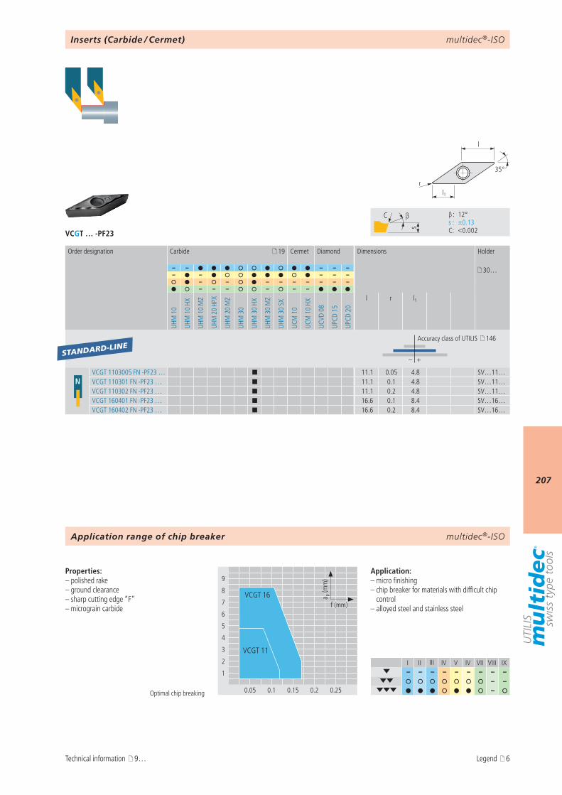
multidec®-ISO
207
VCGT … -PF23
I II III IV V IV VII VIII IX– – – – – – – – –
– – –
9
8
7
6
5
4
3
2
1
0.05 0.1 0.15 0.2 0.25
a p (m
m)
f (mm)VCGT 16
VCGT 11
s
C β
β : 12° s : ±0.13 C : <0.002
l1r
35°
l
19
– – – – – 30…– – – – –
– – – – – – – – –– – – – – –
UHM
10
UHM
10
HX
UHM
10
MZ
UHM
20
HPX
UHM
20
MZ
UHM
30
UHM
30
HX
UHM
30
MZ
UHM
30
SX
UCM
10
UCM
10
HX
UCVD
08
UPCD
15
UPCD
20
l r l1
– +
NVCGT 1103005 FN -PF23 … ¢ 11.1 0.05 4.8 SV…11…VCGT 110301 FN -PF23 … ¢ 11.1 0.1 4.8 SV…11…VCGT 110302 FN -PF23 … ¢ 11.1 0.2 4.8 SV…11…VCGT 160401 FN -PF23 … ¢ 16.6 0.1 8.4 SV…16…VCGT 160402 FN -PF23 … ¢ 16.6 0.2 8.4 SV…16…
STANDARD-LINE
multidec®-ISO
Optimal chip breaking
Properties:– polished rake – ground clearance– sharp cutting edge “F”– micrograin carbide
Application:– micro finishing– chip breaker for materials with difficult chip
control– alloyed steel and stainless steel
Inserts (Carbide / Cermet)
Order designation Carbide Cermet Diamond Dimensions Holder
Accuracy class of UTILIS 146
Application range of chip breaker
Technical information 9… Legend 6
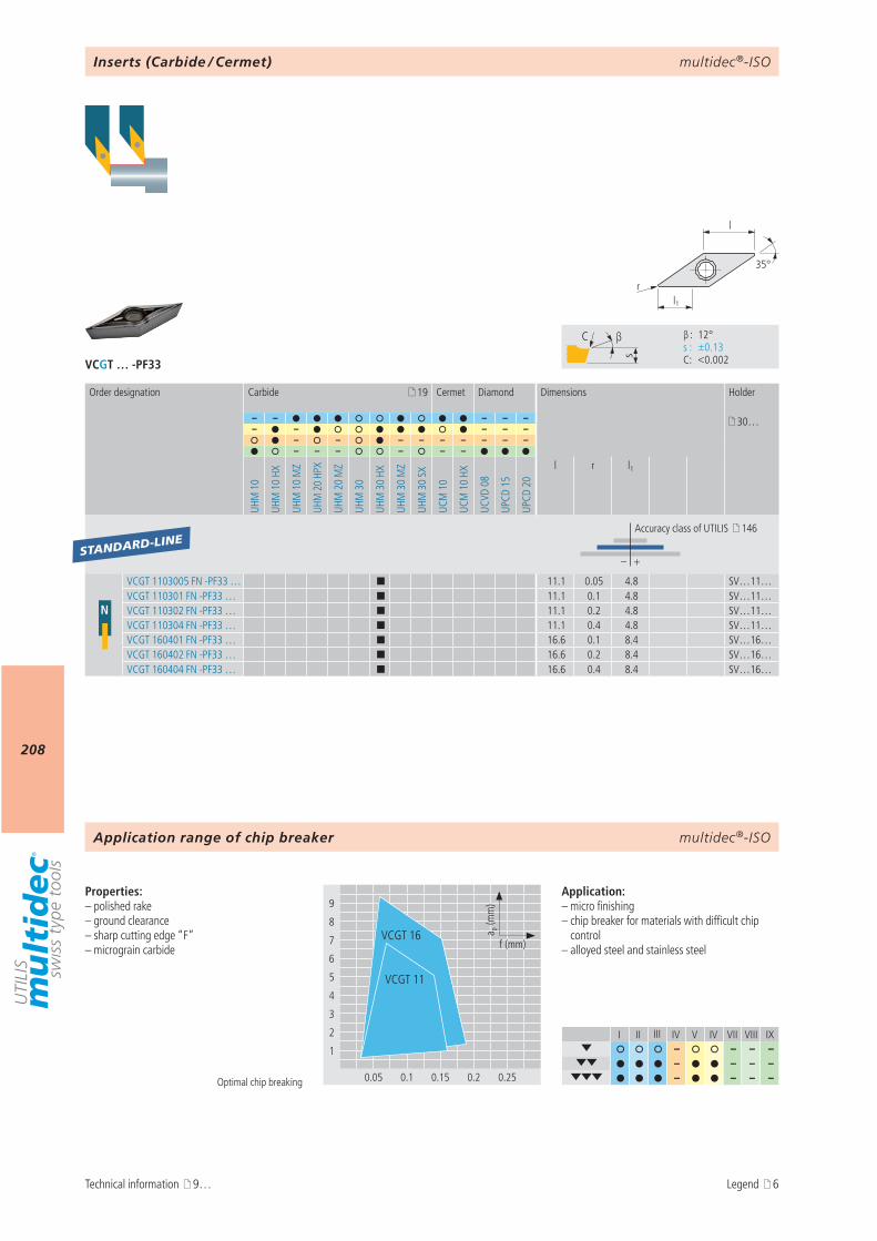
multidec®-ISO
208
VCGT … -PF33
I II III IV V IV VII VIII IX– – – –
– – – – – – – –
9
8
7
6
5
4
3
2
1
0.05 0.1 0.15 0.2 0.25
a p (m
m)
f (mm)VCGT 16
VCGT 11
s
C β
β : 12° s : ±0.13 C : <0.002
l1r
35°
l
19
– – – – – 30…– – – – –
– – – – – – – – –– – – – – –
UHM
10
UHM
10
HX
UHM
10
MZ
UHM
20
HPX
UHM
20
MZ
UHM
30
UHM
30
HX
UHM
30
MZ
UHM
30
SX
UCM
10
UCM
10
HX
UCVD
08
UPCD
15
UPCD
20
l r l1
– +
N
VCGT 1103005 FN -PF33 … ¢ 11.1 0.05 4.8 SV…11…VCGT 110301 FN -PF33 … ¢ 11.1 0.1 4.8 SV…11…VCGT 110302 FN -PF33 … ¢ 11.1 0.2 4.8 SV…11…VCGT 110304 FN -PF33 … ¢ 11.1 0.4 4.8 SV…11…VCGT 160401 FN -PF33 … ¢ 16.6 0.1 8.4 SV…16…VCGT 160402 FN -PF33 … ¢ 16.6 0.2 8.4 SV…16…VCGT 160404 FN -PF33 … ¢ 16.6 0.4 8.4 SV…16…
STANDARD-LINE
multidec®-ISO
Optimal chip breaking
Properties:– polished rake – ground clearance– sharp cutting edge “F”– micrograin carbide
Application:– micro finishing– chip breaker for materials with difficult chip
control– alloyed steel and stainless steel
Inserts (Carbide / Cermet)
Order designation Carbide Cermet Diamond Dimensions Holder
Accuracy class of UTILIS 146
Application range of chip breaker
Technical information 9… Legend 6
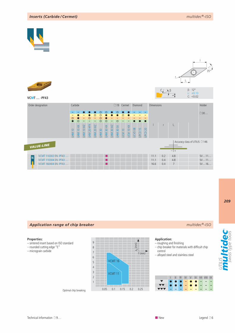
multidec®-ISO
209
VCMT … -PF43
I II III IV V IV VII VIII IX– – – –
– – – – – – – – – – – – –
9
8
7
6
5
4
3
2
1
0.05 0.1 0.15 0.2 0.25
a p (m
m)
f (mm)
VCMT 16
VCMT 11
s
C β
β : 12° s : ±0.13 C : <0.02
l1r
35°
l
19
– – – – – 30…– – – – –
– – – – – – – – –– – – – – –
UHM
10
UHM
10
HX
UHM
10
MZ
UHM
20
HPX
UHM
20
MZ
UHM
30
UHM
30
HX
UHM
30
MZ
UHM
30
SX
UCM
10
UCM
10
HX
UCVD
08
UPCD
15
UPCD
20
l r l1
– +
N VCMT 110302 EN -PF43 … ¢ 11.1 0.2 4.8 SV…11…VCMT 110304 EN -PF43 … ¢ 11.1 0.4 4.8 SV…11…VCMT 160404 EN -PF43 … ¢ 16.6 0.4 7 SV…16…
VALUE-LINE
multidec®-ISO
Optimal chip breaking
Properties:– sintered insert based on ISO standard– rounded cutting edge “E”– micrograin carbide
Application:– roughing and finishing– chip breaker for materials with difficult chip
control– alloyed steel and stainless steel
Inserts (Carbide / Cermet)
Order designation Carbide Cermet Diamond Dimensions Holder
Accuracy class of UTILIS 146
Application range of chip breaker
Technical information 9… ¢ New Legend 6
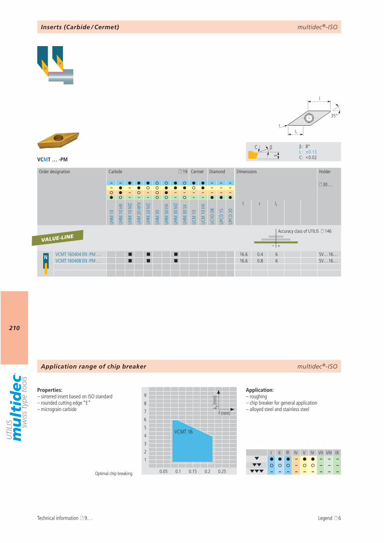
multidec®-ISO
210
VCMT … -PM
I II III IV V IV VII VIII IX– – – –
– – – – – – – – – – – – –
9
8
7
6
5
4
3
2
1
0.05 0.1 0.15 0.2 0.25
a p (m
m)
f (mm)
VCMT 16
s
C β
β : 8° s : ±0.13 C : <0.02
l1r
35°
l
19
– – – – – 30…– – – – –
– – – – – – – – –– – – – – –
UHM
10
UHM
10
HX
UHM
10
MZ
UHM
20
HPX
UHM
20
MZ
UHM
30
UHM
30
HX
UHM
30
MZ
UHM
30
SX
UCM
10
UCM
10
HX
UCVD
08
UPCD
15
UPCD
20
l r l1
– +
N VCMT 160404 EN -PM … ¢ ¢ ¢ 16.6 0.4 6 SV…16…VCMT 160408 EN -PM … ¢ ¢ ¢ 16.6 0.8 6 SV…16…
VALUE-LINE
multidec®-ISO
Optimal chip breaking
Properties:– sintered insert based on ISO standard– rounded cutting edge “E”– micrograin carbide
Application:– roughing– chip breaker for general application– alloyed steel and stainless steel
Inserts (Carbide / Cermet)
Order designation Carbide Cermet Diamond Dimensions Holder
Accuracy class of UTILIS 146
Application range of chip breaker
Technical information 9… Legend 6
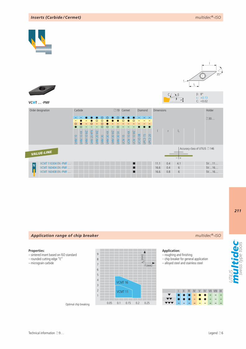
multidec®-ISO
211
VCMT … -PMF
I II III IV V IV VII VIII IX– – – –
– – – – – – – – – – – – –
s
C β
β : 8° s : ±0.13 C : <0.02
l1r
35°
l
19
– – – – – 30…– – – – –
– – – – – – – – – –– – – – – – –
UHM
10
UHM
10
HX
UHM
10
MZ
UHM
20
HPX
UHM
20
MZ
UHM
30
UHM
30
HX
UHM
30
MZ
UHM
30
SX
UCM
10
UCM
10
HX
UCM
10
MZ
UCVD
08
UPCD
15
UPCD
20
l r l1
– +
N VCMT 110304 EN -PMF … ¢ 11.1 0.4 4.1 SV…11…VCMT 160404 EN -PMF … ¢ 16.6 0.4 6 SV…16…VCMT 160408 EN -PMF … ¢ 16.6 0.8 6 SV…16…
VALUE-LINE
9
8
7
6
5
4
3
2
1
0.05 0.1 0.15 0.2 0.25
a p (m
m)
f (mm)
VCMT 16
VCMT 11
multidec®-ISO
Optimal chip breaking
Properties:– sintered insert based on ISO standard– rounded cutting edge “E”– micrograin carbide
Application:– roughing and finishing– chip breaker for general application– alloyed steel and stainless steel
Inserts (Carbide / Cermet)
Order designation Carbide Cermet Diamond Dimensions Holder
Accuracy class of UTILIS 146
Application range of chip breaker
Technical information 9… Legend 6
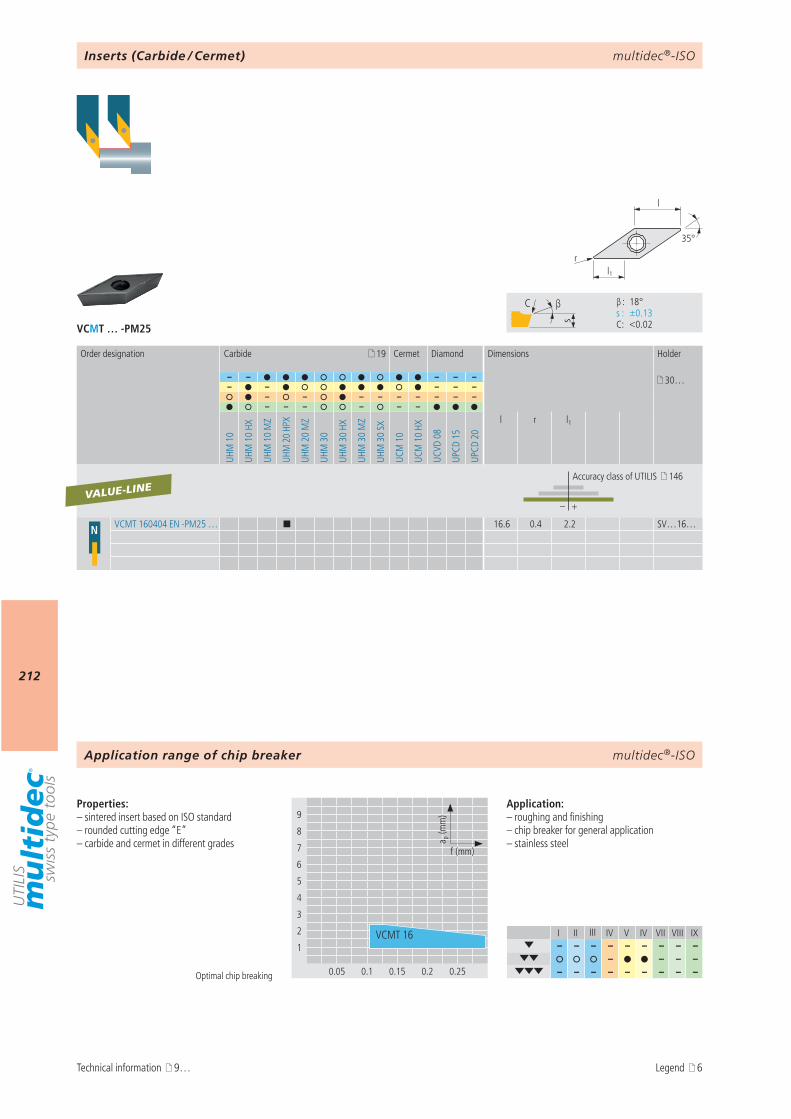
multidec®-ISO
212
VCMT … -PM25
I II III IV V IV VII VIII IX– – – – – – – – –
– – – – – – – – – – – – –
9
8
7
6
5
4
3
2
1
0.05 0.1 0.15 0.2 0.25
a p (m
m)
f (mm)
VCMT 16
s
C β
β : 18° s : ±0.13 C : <0.02
l1r
35°
l
19
– – – – – 30…– – – – –
– – – – – – – – –– – – – – –
UHM
10
UHM
10
HX
UHM
10
MZ
UHM
20
HPX
UHM
20
MZ
UHM
30
UHM
30
HX
UHM
30
MZ
UHM
30
SX
UCM
10
UCM
10
HX
UCVD
08
UPCD
15
UPCD
20
l r l1
– +
N VCMT 160404 EN -PM25 … ¢ 16.6 0.4 2.2 SV…16…
VALUE-LINE
multidec®-ISO
Optimal chip breaking
Properties:– sintered insert based on ISO standard– rounded cutting edge “E”– carbide and cermet in different grades
Application:– roughing and finishing– chip breaker for general application– stainless steel
Inserts (Carbide / Cermet)
Order designation Carbide Cermet Diamond Dimensions Holder
Accuracy class of UTILIS 146
Application range of chip breaker
Technical information 9… Legend 6
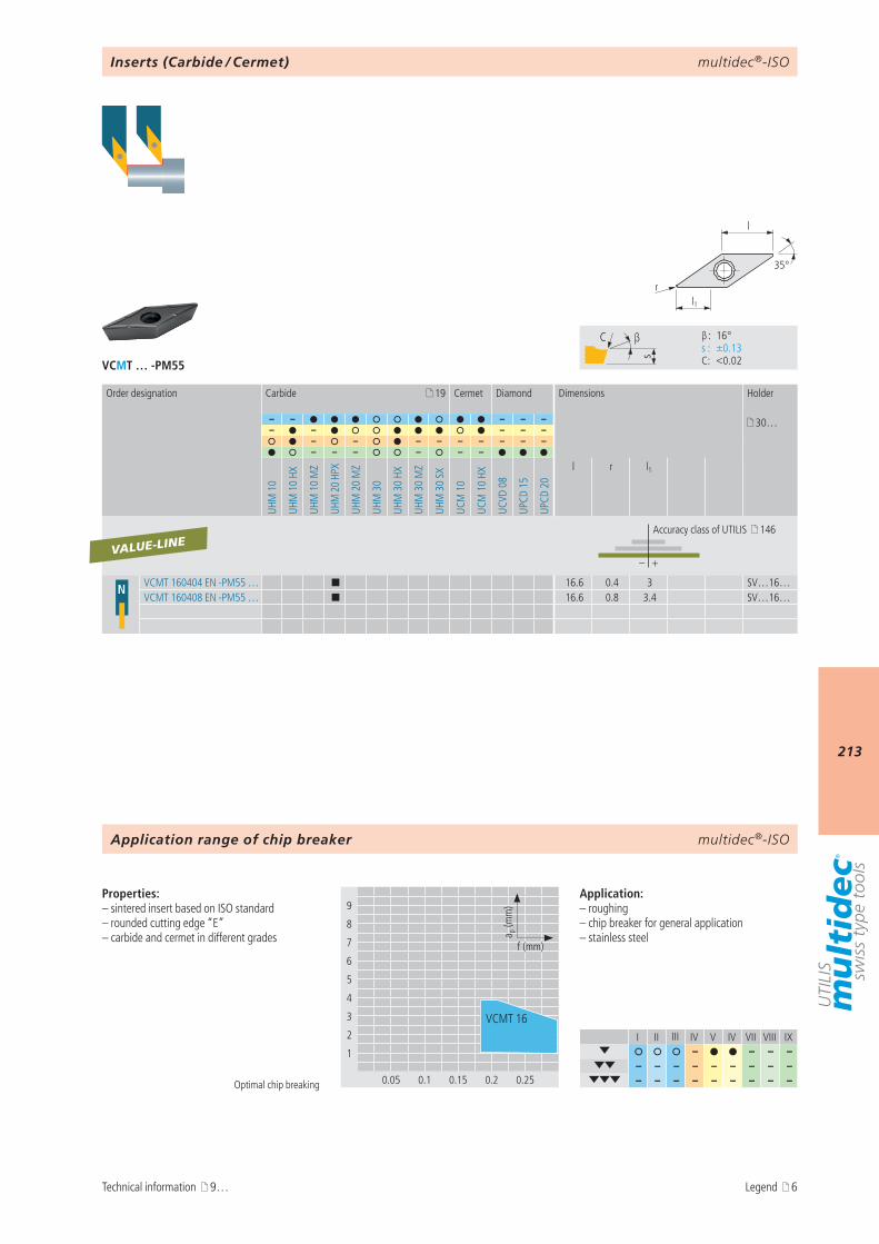
multidec®-ISO
213
VCMT … -PM55
I II III IV V IV VII VIII IX– – – –
– – – – – – – – – – – – – – – – – –
9
8
7
6
5
4
3
2
1
0.05 0.1 0.15 0.2 0.25
a p (m
m)
f (mm)
VCMT 16
s
C β
β : 16° s : ±0.13 C : <0.02
l1r
35°
l
19
– – – – – 30…– – – – –
– – – – – – – – –– – – – – –
UHM
10
UHM
10
HX
UHM
10
MZ
UHM
20
HPX
UHM
20
MZ
UHM
30
UHM
30
HX
UHM
30
MZ
UHM
30
SX
UCM
10
UCM
10
HX
UCVD
08
UPCD
15
UPCD
20
l r l1
– +
N VCMT 160404 EN -PM55 … ¢ 16.6 0.4 3 SV…16…VCMT 160408 EN -PM55 … ¢ 16.6 0.8 3.4 SV…16…
VALUE-LINE
multidec®-ISO
Optimal chip breaking
Properties:– sintered insert based on ISO standard– rounded cutting edge “E”– carbide and cermet in different grades
Application:– roughing– chip breaker for general application– stainless steel
Inserts (Carbide / Cermet)
Order designation Carbide Cermet Diamond Dimensions Holder
Accuracy class of UTILIS 146
Application range of chip breaker
Technical information 9… Legend 6
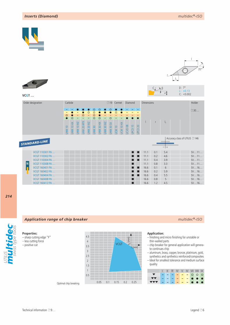
multidec®-ISO
214
VCGT …
I II III IV V IV VII VIII IX– – – – – –
– – – – – – – – – – – –
s
C β
β : 7° s : ±0.13 C : <0.002
4.5
4
3.5
3
2.5
2
1.5
1
0.5
0.05 0.1 0.15 0.2 0.25
VCGT a p (m
m)
f (mm)
l1r
35°
l
19
– – – – – 30…– – – – –
– – – – – – – – –– – – – – –
UHM
10
UHM
10
HX
UHM
10
MZ
UHM
20
HPX
UHM
20
MZ
UHM
30
UHM
30
HX
UHM
30
MZ
UHM
30
SX
UCM
10
UCM
10
HX
UCVD
08
UPCD
15
UPCD
20
l r l1
– +
N
VCGT 110301 FN … ¢ ¢ 11.1 0.1 5.4 SV…11…VCGT 110302 FN … ¢ ¢ 11.1 0.2 4.6 SV…11…VCGT 110304 FN … ¢ ¢ 11.1 0.4 3.9 SV…11…VCGT 110308 FN … ¢ 11.1 0.8 3.3 SV…11…VCGT 160401 FN … ¢ ¢ 16.6 0.1 6 SV…16…VCGT 160402 FN … ¢ ¢ 16.6 0.2 5.9 SV…16…VCGT 160404 FN … ¢ ¢ 16.6 0.4 5.5 SV…16…VCGT 160408 FN … ¢ 16.6 0.8 5 SV…16…VCGT 160412 FN … ¢ 16.6 1.2 4.5 SV…16…
STANDARD-LINE
multidec®-ISO
Optimal chip breaking
Properties:– sharp cutting edge “F”– less cutting force– positive cut
Application:– finishing and micro finishing for unstable or
thin-walled parts– chip breaker for general application will genera-
te continues chip– aluminum, brass, copper, bronze, platinium, gold,
synthetics and synthetics reinforced/composites– Ideal for smallest tolerance and medium surface
quality
Inserts (Diamond)
Order designation Carbide Cermet Diamond Dimensions Holder
Accuracy class of UTILIS 146
Application range of chip breaker
Technical information 9… Legend 6
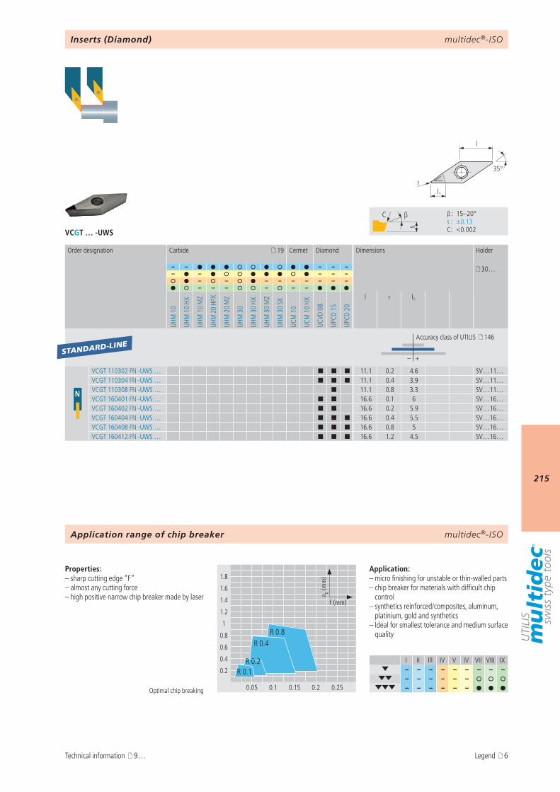
multidec®-ISO
215
VCGT … -UWS
I II III IV V IV VII VIII IX– – – – – – – – –
– – – – – – – – – – – –
s
C β
β : 15–20° s : ±0.13 C : <0.002
1.8
1.6
1.4
1.2
1
0.8
0.6
0.4
0.2
0.05 0.1 0.15 0.2 0.25
a p (m
m)
f (mm)
R 0.4
R 0.1
R 0.8
R 0.2
l1r
35°
l
19
– – – – – 30…– – – – –
– – – – – – – – –– – – – – –
UHM
10
UHM
10
HX
UHM
10
MZ
UHM
20
HPX
UHM
20
MZ
UHM
30
UHM
30
HX
UHM
30
MZ
UHM
30
SX
UCM
10
UCM
10
HX
UCVD
08
UPCD
15
UPCD
20
l r l1
– +
N
VCGT 110302 FN -UWS … ¢ ¢ ¢ 11.1 0.2 4.6 SV…11…VCGT 110304 FN -UWS … ¢ ¢ ¢ 11.1 0.4 3.9 SV…11…VCGT 110308 FN -UWS … ¢ 11.1 0.8 3.3 SV…11…VCGT 160401 FN -UWS … ¢ ¢ 16.6 0.1 6 SV…16…VCGT 160402 FN -UWS … ¢ ¢ 16.6 0.2 5.9 SV…16…VCGT 160404 FN -UWS … ¢ ¢ ¢ 16.6 0.4 5.5 SV…16…VCGT 160408 FN -UWS … ¢ ¢ ¢ 16.6 0.8 5 SV…16…VCGT 160412 FN -UWS … ¢ ¢ ¢ 16.6 1.2 4.5 SV…16…
STANDARD-LINE
multidec®-ISO
Optimal chip breaking
Properties:– sharp cutting edge “F”– almost any cutting force– high positive narrow chip breaker made by laser
Application:– micro finishing for unstable or thin-walled parts– chip breaker for materials with difficult chip
control– synthetics reinforced/composites, aluminum,
platinium, gold and synthetics– Ideal for smallest tolerance and medium surface
quality
Inserts (Diamond)
Order designation Carbide Cermet Diamond Dimensions Holder
Accuracy class of UTILIS 146
Application range of chip breaker
Technical information 9… Legend 6
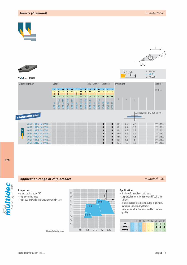
multidec®-ISO
216
VCGT … -UWN
I II III IV V IV VII VIII IX– – – – – –
– – – – – – – – – – – – – – –
s
C β
β : 15–20° s : ±0.13 C : <0.005
1.8
1.6
1.4
1.2
1
0.8
0.6
0.4
0.2
0.05 0.1 0.15 0.2 0.25
R 0.4
R 0.8
R 0.2
a p (m
m)
f (mm)
l1r
35°
l
19
– – – – – 30…– – – – –
– – – – – – – – –– – – – – –
UHM
10
UHM
10
HX
UHM
10
MZ
UHM
20
HPX
UHM
20
MZ
UHM
30
UHM
30
HX
UHM
30
MZ
UHM
30
SX
UCM
10
UCM
10
HX
UCVD
08
UPCD
15
UPCD
20
l r l1
– +
N
VCGT 110302 FN -UWN … ¢ ¢ 11.1 0.2 4.6 SV…11…VCGT 110304 FN -UWN … ¢ ¢ 11.1 0.4 3.9 SV…11…VCGT 110308 FN -UWN … ¢ ¢ 11.1 0.8 3.3 SV…11…VCGT 160402 FN -UWN … ¢ ¢ 16.6 0.2 5.9 SV…16…VCGT 160404 FN -UWN … ¢ ¢ 16.6 0.4 5.5 SV…16…VCGT 160408 FN -UWN … ¢ ¢ 16.6 0.8 5 SV…16…VCGT 160412 FN -UWN … ¢ ¢ 16.6 1.2 4.5 SV…16…
STANDARD-LINE
multidec®-ISO
Optimal chip breaking
Properties:– sharp cutting edge “F”– higher cutting force– high positive wide chip breaker made by laser
Application:– finishing for stable or solid parts– chip breaker for materials with difficult chip
control– synthetics reinforced/composites, aluminum,
platinium, gold and synthetics– Ideal for smallest tolerance and best surface
quality
Inserts (Diamond)
Order designation Carbide Cermet Diamond Dimensions Holder
Accuracy class of UTILIS 146
Application range of chip breaker
Technical information 9… Legend 6
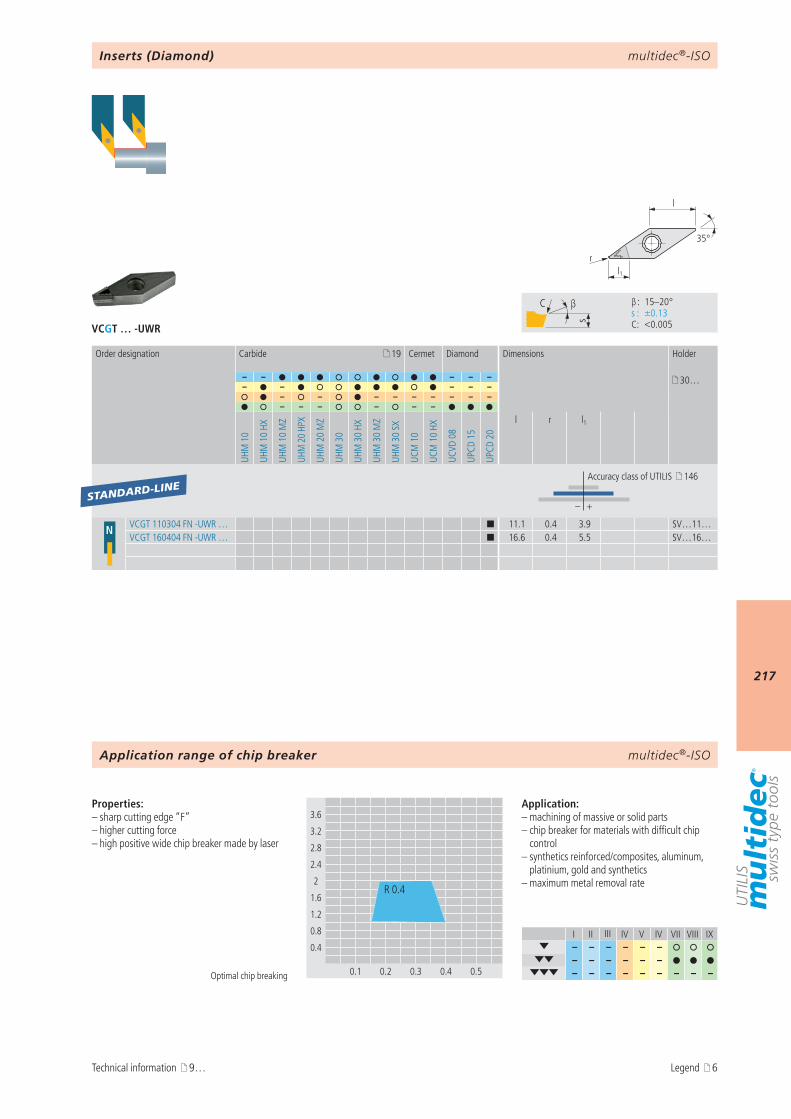
multidec®-ISO
217
VCGT … -UWR
l1r
35°
l
19
– – – – – 30…– – – – –
– – – – – – – – –– – – – – –
UHM
10
UHM
10
HX
UHM
10
MZ
UHM
20
HPX
UHM
20
MZ
UHM
30
UHM
30
HX
UHM
30
MZ
UHM
30
SX
UCM
10
UCM
10
HX
UCVD
08
UPCD
15
UPCD
20
l r l1
– +
N VCGT 110304 FN -UWR … ¢ 11.1 0.4 3.9 SV…11…VCGT 160404 FN -UWR … ¢ 16.6 0.4 5.5 SV…16…
STANDARD-LINE
a p (m
m)
f (mm)
I II III IV V IV VII VIII IX– – – – – –
– – – – – – – – – – – – – – –
s
C β
β : 15–20° s : ±0.13 C : <0.005
3.6
3.2
2.8
2.4
2
1.6
1.2
0.8
0.4
0.1 0.2 0.3 0.4 0.5
R 0.4
multidec®-ISO
Inserts (Diamond)
Order designation Carbide Cermet Diamond Dimensions Holder
Accuracy class of UTILIS 146
Optimal chip breaking
Properties:– sharp cutting edge “F”– higher cutting force– high positive wide chip breaker made by laser
Application:– machining of massive or solid parts– chip breaker for materials with difficult chip
control– synthetics reinforced/composites, aluminum,
platinium, gold and synthetics– maximum metal removal rate
Application range of chip breaker
Technical information 9… Legend 6
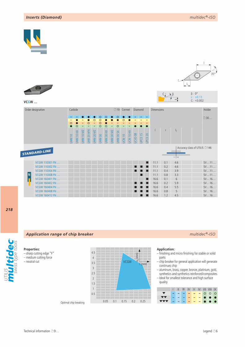
multidec®-ISO
218
VCGW …
I II III IV V IV VII VIII IX– – – – – –
– – – – – – – – – – – –
s
C β
β : 0° s : ±0.13 C : <0.002
4.5
4
3.5
3
2.5
2
1.5
1
0.5
0.05 0.1 0.15 0.2 0.25
VCGW a p (m
m)
f (mm)
l1r
35°
l
19
– – – – – 30…– – – – –
– – – – – – – – –– – – – – –
UHM
10
UHM
10
HX
UHM
10
MZ
UHM
20
HPX
UHM
20
MZ
UHM
30
UHM
30
HX
UHM
30
MZ
UHM
30
SX
UCM
10
UCM
10
HX
UCVD
08
UPCD
15
UPCD
20
l r l1
– +
N
VCGW 110301 FN … ¢ 11.1 0.1 4.6 SV…11…VCGW 110302 FN … ¢ ¢ ¢ 11.1 0.2 4.6 SV…11…VCGW 110304 FN … ¢ ¢ ¢ 11.1 0.4 3.9 SV…11…VCGW 110308 FN … ¢ 11.1 0.8 3.3 SV…11…VCGW 160401 FN … ¢ 16.6 0.1 6 SV…16…VCGW 160402 FN … ¢ ¢ ¢ 16.6 0.2 5.9 SV…16…VCGW 160404 FN … ¢ ¢ ¢ 16.6 0.4 5.5 SV…16…VCGW 160408 FN … ¢ ¢ ¢ 16.6 0.8 5 SV…16…VCGW 160412 FN … ¢ ¢ 16.6 1.2 4.5 SV…16…
STANDARD-LINE
multidec®-ISO
Optimal chip breaking
Properties:– sharp cutting edge “F”– medium cutting force– neutral cut
Application:– finishing and micro finishing for stable or solid
parts– chip breaker for general application will generate
continues chip– aluminum, brass, copper, bronze, platinium, gold,
synthetics and synthetics reinforced/composites– Ideal for smallest tolerance and high surface
quality
Inserts (Diamond)
Order designation Carbide Cermet Diamond Dimensions Holder
Accuracy class of UTILIS 146
Application range of chip breaker
Technical information 9… Legend 6

multidec®-ISO
219
AttentionPlease note the legend 6…
Notes
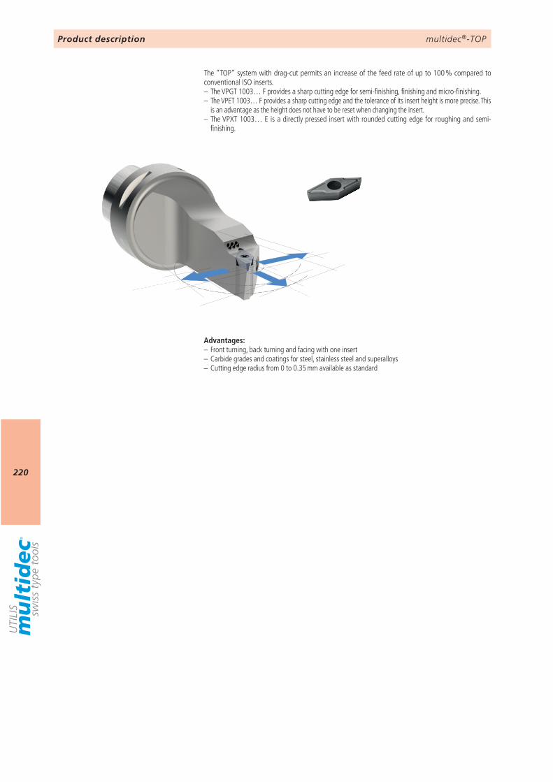
multidec®-TOP
220
Product description
The “TOP” system with drag-cut permits an increase of the feed rate of up to 100 % compared to conventional ISO inserts.– The VPGT 1003… F provides a sharp cutting edge for semi-finishing, finishing and micro-finishing.– The VPET 1003… F provides a sharp cutting edge and the tolerance of its insert height is more precise. This
is an advantage as the height does not have to be reset when changing the insert.– The VPXT 1003… E is a directly pressed insert with rounded cutting edge for roughing and semi-
finishing.
Advantages:– Front turning, back turning and facing with one insert– Carbide grades and coatings for steel, stainless steel and superalloys– Cutting edge radius from 0 to 0.35 mm available as standard
multidec®-TOP
221
9 VPET … TOP 222VPGT … TOP 223VPXT … TOP 224
multidec®-TOPOverview type VP… (35°)
Technical information Inserts (carbide / cermet)
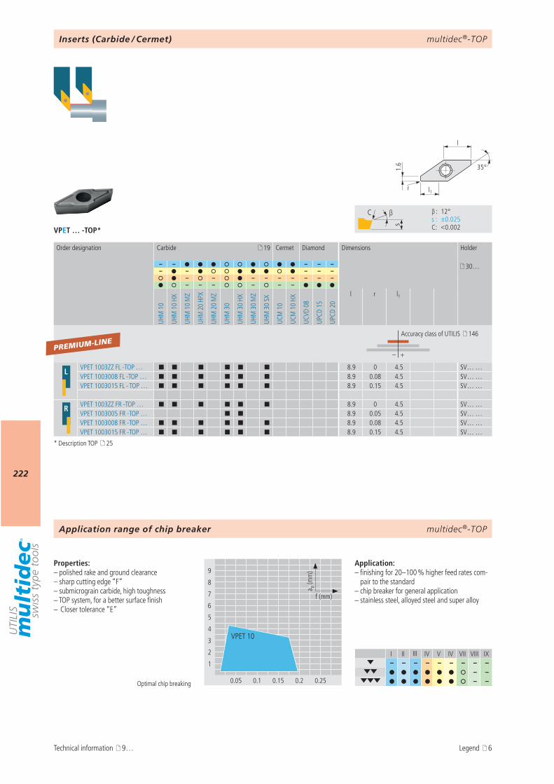
multidec®-TOP
222
I II III IV V IV VII VIII IX– – – – – – – – –
– – – –
9
8
7
6
5
4
3
2
1
0.05 0.1 0.15 0.2 0.25
a p (m
m)
f (mm)
VPET 10
s
C β
β : 12° s : ±0.025 C : <0.002
l1r
35°
l
1.6
VPET … -TOP*
19
– – – – – 30…– – – – –
– – – – – – – – –– – – – – –
UHM
10
UHM
10
HX
UHM
10
MZ
UHM
20
HPX
UHM
20
MZ
UHM
30
UHM
30
HX
UHM
30
MZ
UHM
30
SX
UCM
10
UCM
10
HX
UCVD
08
UPCD
15
UPCD
20
l r l1
– +
L VPET 1003ZZ FL -TOP … ¢ ¢ ¢ ¢ ¢ ¢ 8.9 0 4.5 SV… …VPET 1003008 FL -TOP … ¢ ¢ ¢ ¢ ¢ ¢ 8.9 0.08 4.5 SV… …VPET 1003015 FL - TOP … ¢ ¢ ¢ ¢ ¢ ¢ 8.9 0.15 4.5 SV… …
R VPET 1003ZZ FR -TOP … ¢ ¢ ¢ ¢ ¢ ¢ 8.9 0 4.5 SV… …VPET 1003005 FR -TOP … ¢ ¢ 8.9 0.05 4.5 SV… …VPET 1003008 FR -TOP … ¢ ¢ ¢ ¢ ¢ ¢ 8.9 0.08 4.5 SV… …VPET 1003015 FR -TOP … ¢ ¢ ¢ ¢ ¢ ¢ 8.9 0.15 4.5 SV… …
PREMIUM-LINE
multidec®-TOP
Properties:– polished rake and ground clearance– sharp cutting edge “F”– submicrograin carbide, high toughness– TOP system, for a better surface finish– Closer tolerance “E”
Application:– finishing for 20–100 % higher feed rates com-
pair to the standard– chip breaker for general application– stainless steel, alloyed steel and super alloy
Optimal chip breaking
Inserts (Carbide / Cermet)
Order designation Carbide Cermet Diamond Dimensions Holder
Accuracy class of UTILIS 146
Application range of chip breaker
Technical information 9…
* Description TOP 25
Legend 6
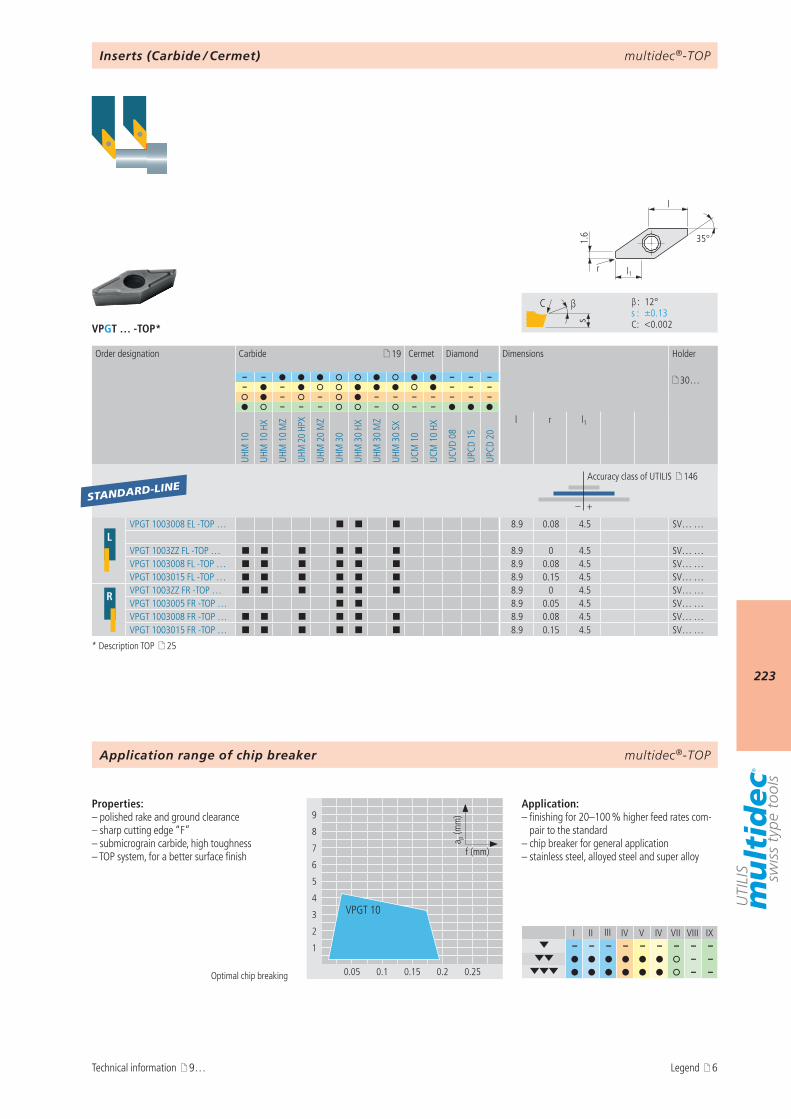
multidec®-TOP
223
VPGT … -TOP*
9
8
7
6
5
4
3
2
1
0.05 0.1 0.15 0.2 0.25
a p (m
m)
f (mm)
VPGT 10
I II III IV V IV VII VIII IX– – – – – – – – –
– – – –
s
C β
β : 12° s : ±0.13 C : <0.002
l1r
35°
l
1.6
19
– – – – – 30…– – – – –
– – – – – – – – –– – – – – –
UHM
10
UHM
10
HX
UHM
10
MZ
UHM
20
HPX
UHM
20
MZ
UHM
30
UHM
30
HX
UHM
30
MZ
UHM
30
SX
UCM
10
UCM
10
HX
UCVD
08
UPCD
15
UPCD
20
l r l1
– +
LVPGT 1003008 EL -TOP … ¢ ¢ ¢ 8.9 0.08 4.5 SV… …
VPGT 1003ZZ FL -TOP … ¢ ¢ ¢ ¢ ¢ ¢ 8.9 0 4.5 SV… …VPGT 1003008 FL -TOP … ¢ ¢ ¢ ¢ ¢ ¢ 8.9 0.08 4.5 SV… …VPGT 1003015 FL -TOP … ¢ ¢ ¢ ¢ ¢ ¢ 8.9 0.15 4.5 SV… …
R VPGT 1003ZZ FR -TOP … ¢ ¢ ¢ ¢ ¢ ¢ 8.9 0 4.5 SV… …VPGT 1003005 FR -TOP … ¢ ¢ 8.9 0.05 4.5 SV… …VPGT 1003008 FR -TOP … ¢ ¢ ¢ ¢ ¢ ¢ 8.9 0.08 4.5 SV… …VPGT 1003015 FR -TOP … ¢ ¢ ¢ ¢ ¢ ¢ 8.9 0.15 4.5 SV… …
STANDARD-LINE
multidec®-TOP
Properties:– polished rake and ground clearance– sharp cutting edge “F”– submicrograin carbide, high toughness– TOP system, for a better surface finish
Application:– finishing for 20–100 % higher feed rates com-
pair to the standard– chip breaker for general application– stainless steel, alloyed steel and super alloy
Optimal chip breaking
Inserts (Carbide / Cermet)
Order designation Carbide Cermet Diamond Dimensions Holder
Accuracy class of UTILIS 146
Application range of chip breaker
Technical information 9…
* Description TOP 25
Legend 6
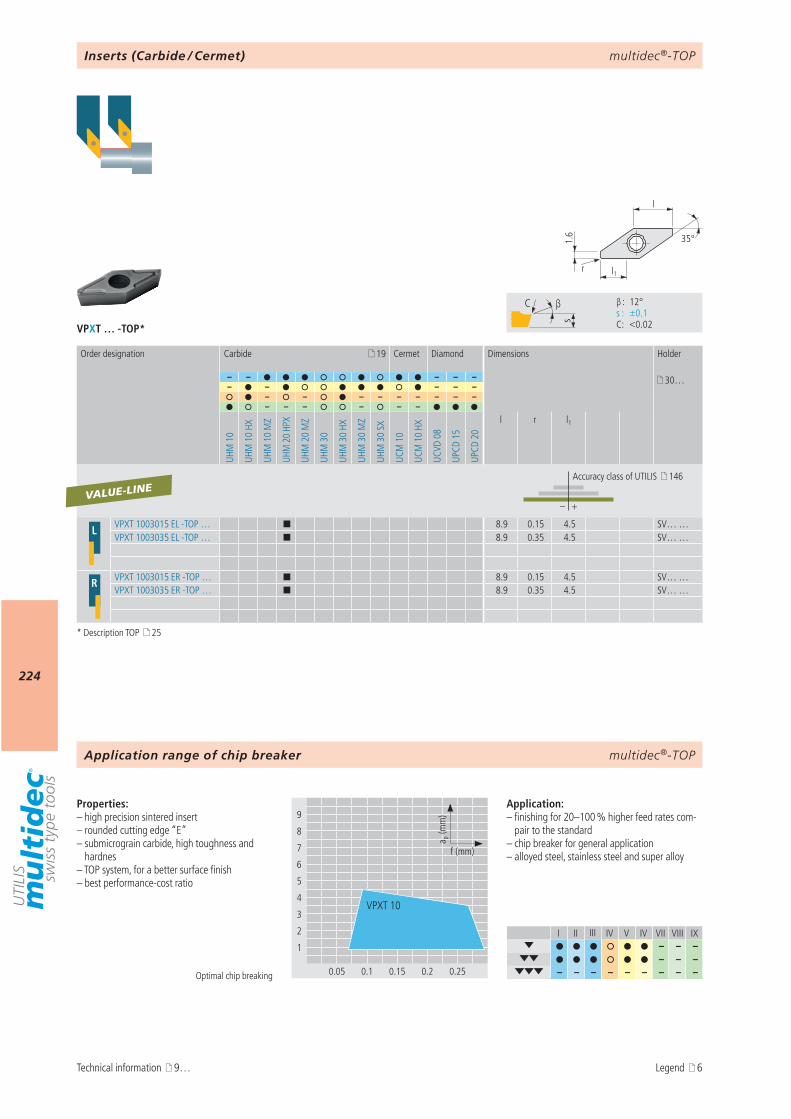
multidec®-TOP
224
VPXT … -TOP*
9
8
7
6
5
4
3
2
1
0.05 0.1 0.15 0.2 0.25
a p (m
m)
f (mm)
VPXT 10
I II III IV V IV VII VIII IX– – –
– – – – – – – – – – – –
s
C β
β : 12° s : ±0.1 C : <0.02
l1r
35°
l
1.6
19
– – – – – 30…– – – – –
– – – – – – – – –– – – – – –
UHM
10
UHM
10
HX
UHM
10
MZ
UHM
20
HPX
UHM
20
MZ
UHM
30
UHM
30
HX
UHM
30
MZ
UHM
30
SX
UCM
10
UCM
10
HX
UCVD
08
UPCD
15
UPCD
20
l r l1
– +
L VPXT 1003015 EL -TOP … ¢ 8.9 0.15 4.5 SV… …VPXT 1003035 EL -TOP … ¢ 8.9 0.35 4.5 SV… …
R VPXT 1003015 ER -TOP … ¢ 8.9 0.15 4.5 SV… …VPXT 1003035 ER -TOP … ¢ 8.9 0.35 4.5 SV… …
VALUE-LINE
multidec®-TOP
Properties:– high precision sintered insert– rounded cutting edge “E”– submicrograin carbide, high toughness and
hardnes– TOP system, for a better surface finish– best performance-cost ratio
Application:– finishing for 20–100 % higher feed rates com-
pair to the standard– chip breaker for general application– alloyed steel, stainless steel and super alloy
Optimal chip breaking
Inserts (Carbide / Cermet)
Order designation Carbide Cermet Diamond Dimensions Holder
Accuracy class of UTILIS 146
Application range of chip breaker
Technical information 9…
* Description TOP 25
Legend 6

multidec®-TOP
225
AttentionPlease note the legend 6…
Notes
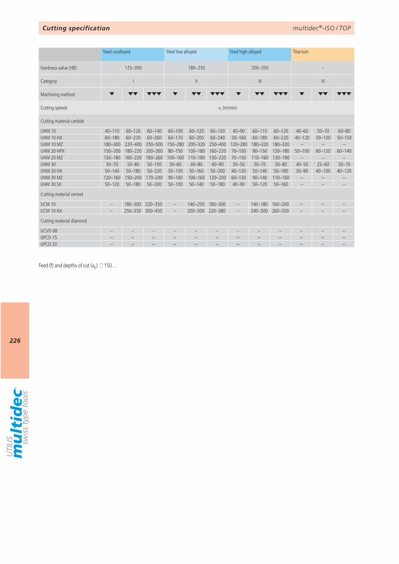
multidec®-ISO / TOP
226
125–300 180–250 200–350 –
I II III IV
vc (m/min)
UHM 10 40–110 60–120 60–140 60–100 60–120 60–130 40–90 60–110 60–120 40–60 50–70 60–80UHM 10 HX 60–180 60–220 60–260 60–170 60–200 60–240 50–160 60–180 60–220 40–120 50–130 50–150UHM 10 MZ 180–300 220–400 250–500 150–280 200–320 250–400 120–280 180–320 180–320 – – –UHM 20 HPX 150–200 180–220 200–260 80–150 100–180 160–220 70–100 90–150 120–180 50–100 60–120 60–140UHM 20 MZ 130–180 160–220 180–260 100–160 110–180 130–220 70–150 110–160 130–190 – – –UHM 30 30–70 50–80 50–100 30–60 40–80 40–90 30–50 30–70 30–80 40–50 25–60 30–70UHM 30 HX 50–140 50–180 50–220 50–130 50–160 50–200 40–120 50–140 50–180 30–90 40–100 40–120UHM 30 MZ 120–160 150–200 170–240 90–140 100–160 120–200 60–130 90–140 110–160 – – –UHM 30 SX 50–120 50–180 50–200 50–100 50–140 50–180 40–90 50–120 50–160 – – –
UCM 10 – 180–300 220–350 – 140–250 180–300 – 140–180 160–200 – – –UCM 10 HX – 250–350 300–450 – 200–300 220–380 – 240–300 260–350 – – –
UCVD 08 – – – – – – – – – – – –UPCD 15 – – – – – – – – – – – –UPCD 20 – – – – – – – – – – – –
Cutting specification
Steel unalloyed Steel low alloyed Steel high alloyed Titanium
Hardness value (HB)
Category
Machining method
Cutting speeds
Cutting material carbide
Cutting material cermet
Cutting material diamond
Feed (f) and depths of cut (ap) 150…
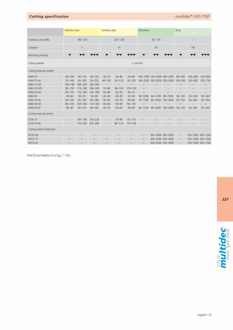
multidec®-ISO / TOP
227
180–220 220 –330 60–130 –
V VI VII VIII
vc (m/min)
UHM 10 40–100 40–110 40–120 30–70 30–80 30–80 100–1500 120–2000 160–2500 80–300 100–400 120–500UHM 10 HX 50–140 50–180 50–220 40–100 50–110 50–130 140–2500 160–3000 200–3000 100–450 100–600 100–750UHM 10 MZ 100–180 180–250 220–300 – – – – – – – – –UHM 20 HPX 90–150 110–180 160–200 70–90 90–120 110–150 – – – – – –UHM 20 MZ 90–150 110–160 130–180 50–80 30–50 40–70 – – – – – –UHM 30 30–60 30–70 30–80 20–30 20–40 20–40 50–1000 60–1200 80–1500 40–100 50–140 50–160UHM 30 HX 40–100 40–140 40–180 30–60 40–70 40–90 70–1500 80–2000 100–3000 50–150 50–200 50–250UHM 30 MZ 80–130 100–140 110–160 40–80 50–90 90–110 – – – – – –UHM 30 SX 30–90 40–120 40–160 20–50 30–60 30–80 60–1200 80–2000 100–3000 50–120 50–180 50–200
UCM 10 – 140–180 150–220 – 70–90 70–110 – – – – – –UCM 10 HX – 170–230 220–280 – 80–110 110–140 – – – – – –
UCVD 08 – – – – – – – 300–2000 300–3000 – 250–1000 300–1500UPCD 15 – – – – – – – 300–2000 300–3000 – 250–1000 300–1500UPCD 20 – – – – – – – 300–2000 300–3000 – 250–1000 300–1500
Cutting specification
Stainless steel Stainless steel Aluminum Brass
Hardness value (HB)
Category
Machining method
Cutting speeds
Cutting material carbide
Cutting material cermet
Cutting material diamond
Feed (f) and depths of cut (ap) 150…
Legend 6
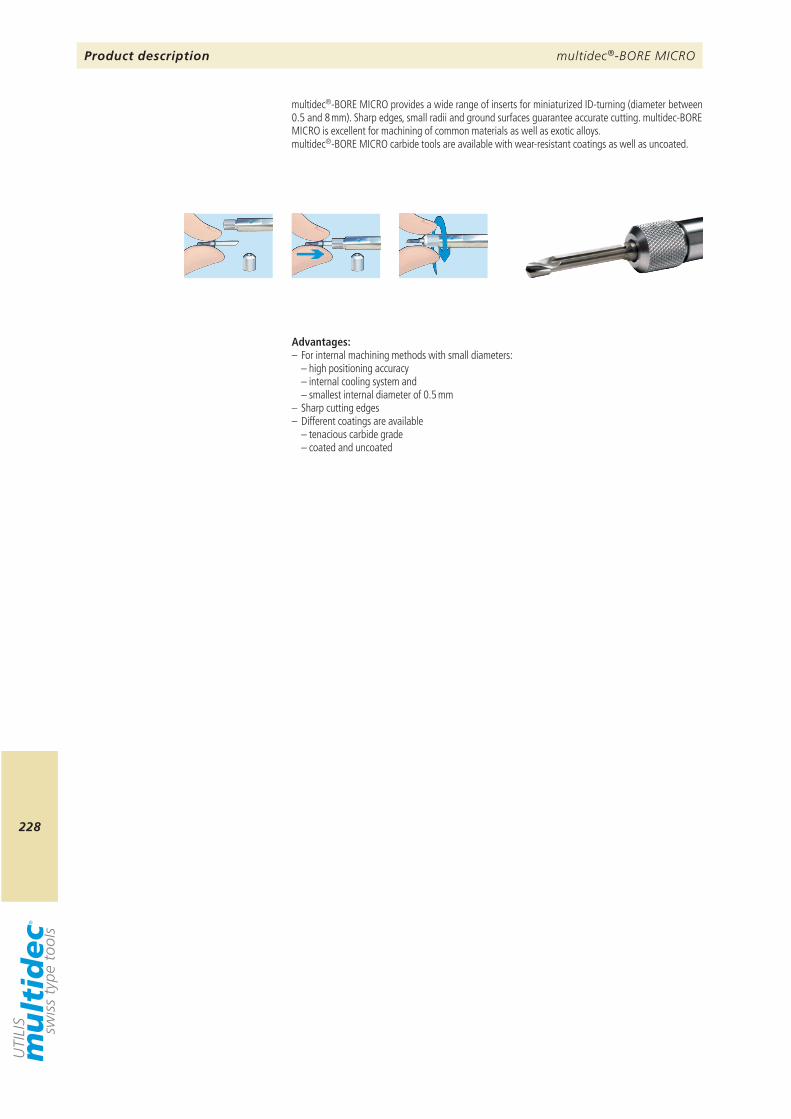
multidec®-BORE MICRO
228
Product description
multidec®-BORE MICRO provides a wide range of inserts for miniaturized ID-turning (diameter between 0.5 and 8 mm). Sharp edges, small radii and ground surfaces guarantee accurate cutting. multidec-BORE MICRO is excellent for machining of common materials as well as exotic alloys. multidec®-BORE MICRO carbide tools are available with wear-resistant coatings as well as uncoated.
Advantages:– For internal machining methods with small diameters: – high positioning accuracy – internal cooling system and – smallest internal diameter of 0.5 mm– Sharp cutting edges– Different coatings are available – tenacious carbide grade – coated and uncoated
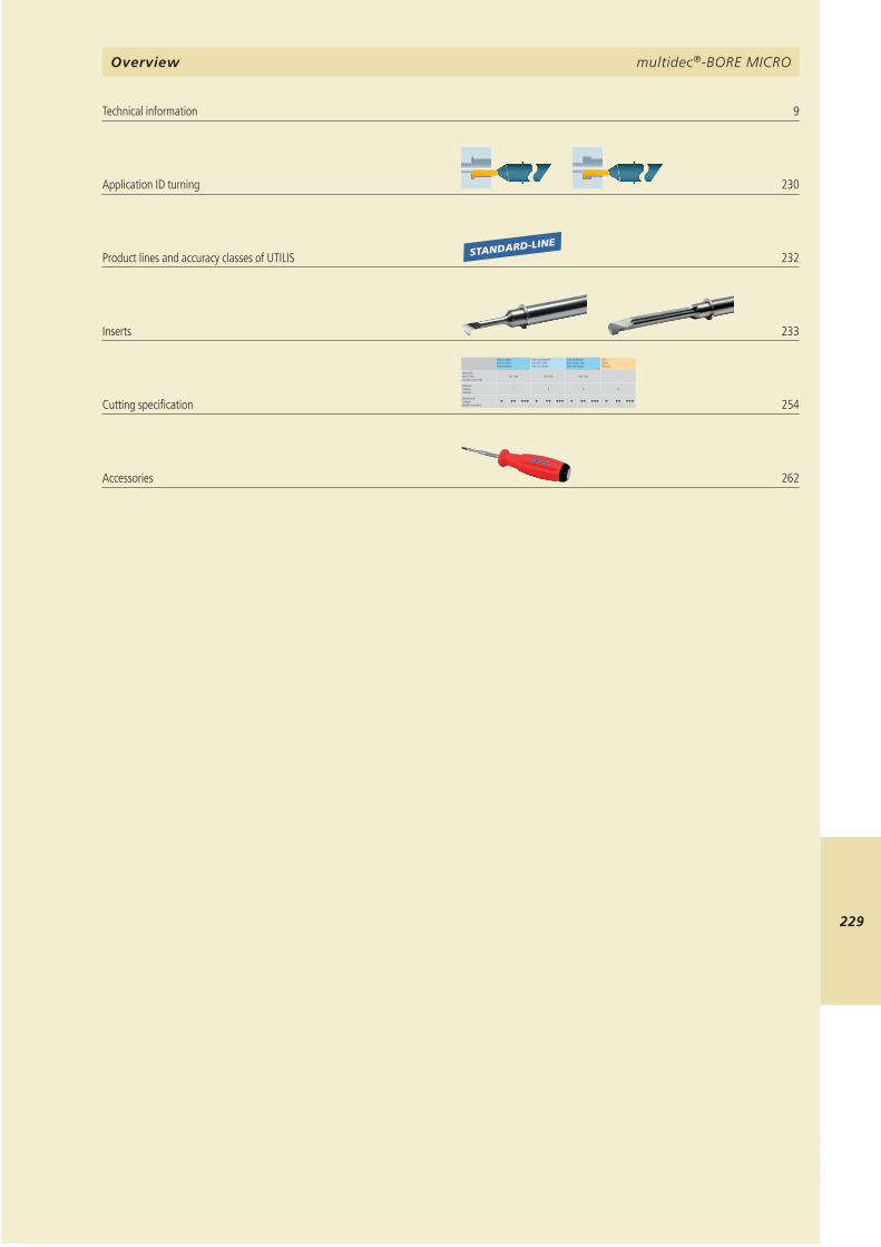
multidec®-BORE MICRO
229
9 230 STANDARD-LINE
232
233
Stahl unlegiertAcier non alliéSteel unalloyed
Stahl niedriglegiertAcier faibl. alliéSteel low alloyed
Stahl hochlegiertAcier fortem. alliéSteel high alloyed
TitanTitaneTitanium
Härte (HB)Dureté (HB)Hardness value (HB)
125–300 180–250 200–350 –
KategorieCatégrieCategory
I II III IV
BearbeitungUsinageMachining method
254 262
multidec®-BORE MICRO
Technical information Application ID turning Product lines and accuracy classes of UTILIS Inserts Cutting specification Accessories
Overview
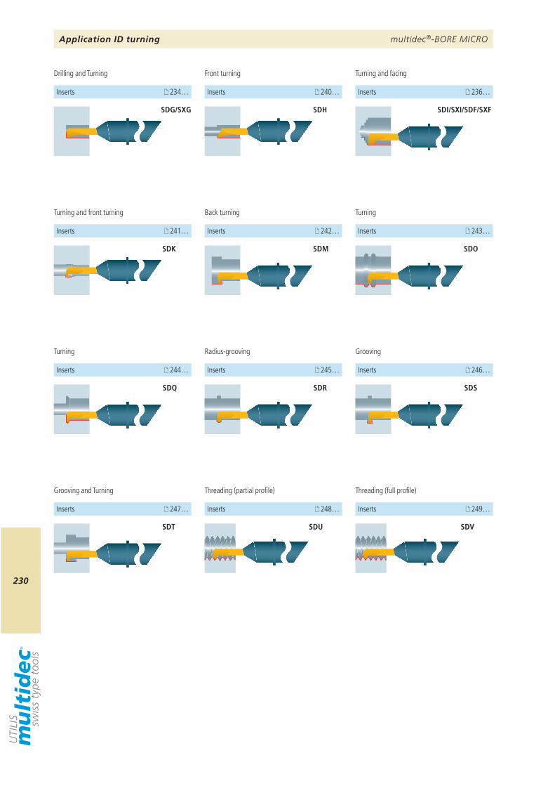
multidec®-BORE MICRO
230
234… 240… 236…
241… 243… 242…
244… 245…
SDG/SXG SDH SDI/SXI/SDF/SXF
SDK SDM SDO
SDQ
SDT
SDR
247… 248…
SDU
246…
SDS
249…
SDV
Application ID turning
Radius-grooving
Drilling and Turning Front turning
Turning and front turning Back turning
Grooving and Turning
Turning
Turning and facing
Inserts
Turning
Inserts Inserts
Inserts InsertsInserts
Inserts Inserts
Inserts
Threading (partial profile)
Inserts
Grooving
Inserts
Threading (full profile)
Inserts
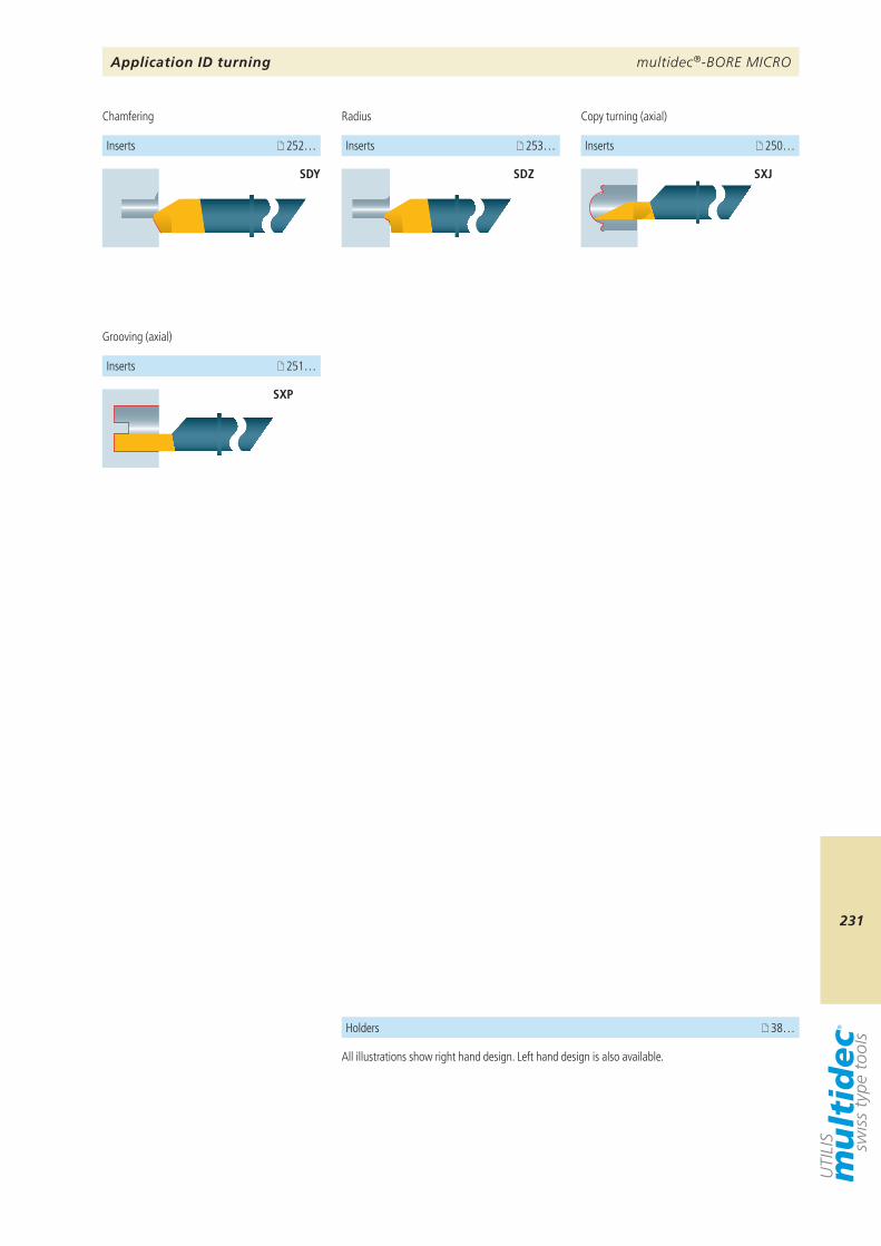
multidec®-BORE MICRO
231
252…
SDY SXJ
SXP
251…
250…
38…
253…
SDZ
Application ID turning
Chamfering
Inserts
Copy turning (axial)
Grooving (axial)
Inserts
Inserts
Holders
All illustrations show right hand design. Left hand design is also available.
Radius
Inserts
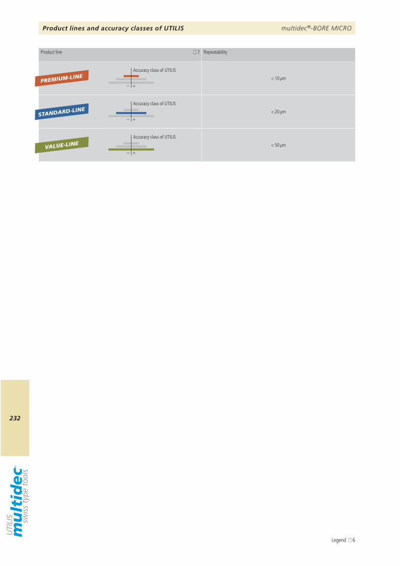
multidec®-BORE MICRO
232
7
– +
– +
– +
PREMIUM-LINE
VALUE-LINE
STANDARD-LINE
Product lines and accuracy classes of UTILIS
Product line Repeatability
Accuracy class of UTILIS
< 10 µm
Accuracy class of UTILIS
< 20 µm
Accuracy class of UTILIS
< 50 µm
Legend 6
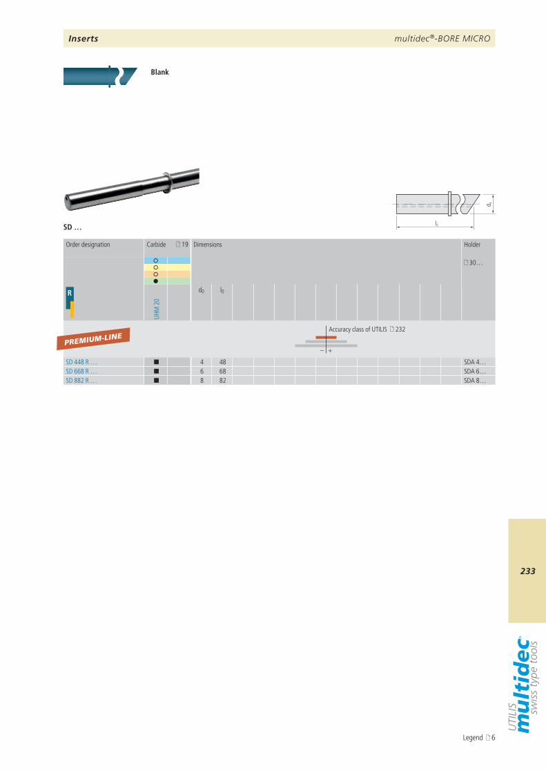
multidec®-BORE MICRO
233
l0
d 0
SD …
19
30…
R
UHM
20
d0 l0
– +
SD 448 R … ¢ 4 48 SDA 4…SD 668 R … ¢ 6 68 SDA 6…SD 882 R … ¢ 8 82 SDA 8…
PREMIUM-LINE
Inserts
Blank
Order designation Carbide Dimensions Holder
Accuracy class of UTILIS 232
Legend 6
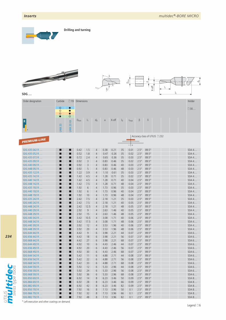
multidec®-BORE MICRO
234
a d 0
l1
l0
D min
X-of
f
β
δ
r max
SDG …
19
30…
R
* UHM
20
UHM
20
HX
Dmin l1 d0 a X-off l0 rmax β δ
– +
SDG 435 042 R … ¢ ¢ 0.42 1.5 4 0.38 0.21 35 0.01 2.5° 89.5° SDA 4…SDG 435 052 R … ¢ ¢ 0.52 1.8 4 0.47 0.26 35 0.02 2.5° 89.5° SDA 4…SDG 435 072 R … ¢ ¢ 0.72 2.4 4 0.65 0.36 35 0.03 2.5° 89.5° SDA 4…SDG 435 092 R … ¢ ¢ 0.92 3 4 0.83 0.46 35 0.02 2.5° 89.5° SDA 4…SDG 440 092 R … ¢ ¢ 0.92 3 4 0.83 0.46 40 0.03 2.5° 89.5° SDA 4…SDG 448 092 R … ¢ ¢ 0.92 5 4 0.83 0.46 48 0.03 2.5° 89.5° SDA 4…SDG 435 122 R … ¢ ¢ 1.22 3.9 4 1.10 0.61 35 0.03 2.5° 89.5° SDA 4…SDG 435 142 R … ¢ ¢ 1.42 4.5 4 1.28 0.71 35 0.02 2.5° 89.5° SDA 4…SDG 440 142 R … ¢ ¢ 1.42 4.5 4 1.28 0.71 40 0.04 2.5° 89.5° SDA 4…SDG 448 142 R … ¢ ¢ 1.42 7.5 4 1.28 0.71 48 0.04 2.5° 89.5° SDA 4…SDG 435 192 R … ¢ ¢ 1.92 6 4 1.73 0.96 35 0.03 2.5° 89.5° SDA 4…SDG 440 192 R … ¢ ¢ 1.92 6 4 1.73 0.96 40 0.04 2.5° 89.5° SDA 4…SDG 448 192 R … ¢ ¢ 1.92 10 4 1.73 0.96 48 0.04 2.5° 89.5° SDA 4…SDG 435 242 R … ¢ ¢ 2.42 7.5 4 2.18 1.21 35 0.03 2.5° 89.5° SDA 4…SDG 440 242 R … ¢ ¢ 2.42 7.5 4 2.18 1.21 40 0.05 2.5° 89.5° SDA 4…SDG 448 242 R … ¢ ¢ 2.42 12.5 4 2.18 1.21 48 0.05 2.5° 89.5° SDA 4…SDG 440 292 R … ¢ ¢ 2.92 9 4 2.63 1.46 40 0.05 2.5° 89.5° SDA 4…SDG 448 292 R … ¢ ¢ 2.92 15 4 2.63 1.46 48 0.05 2.5° 89.5° SDA 4…SDG 440 342 R … ¢ ¢ 3.42 10.5 4 3.08 1.71 40 0.06 2.5° 89.5° SDA 4…SDG 448 342 R … ¢ ¢ 3.42 17.5 4 3.08 1.71 48 0.06 2.5° 89.5° SDA 4…SDG 440 392 R … ¢ ¢ 3.92 12 4 3.53 1.96 40 0.06 2.5° 89.5° SDA 4…SDG 448 392 R … ¢ ¢ 3.92 20 4 3.53 1.96 48 0.06 2.5° 89.5° SDA 4…SDG 644 442 R … ¢ ¢ 4.42 9 6 3.98 2.21 44 0.07 2.5° 89.5° SDA 6…SDG 656 442 R … ¢ ¢ 4.42 18 6 3.98 2.21 56 0.07 2.5° 89.5° SDA 6…SDG 668 442 R … ¢ ¢ 4.42 27 6 3.98 2.21 68 0.07 2.5° 89.5° SDA 6…SDG 644 492 R … ¢ ¢ 4.92 10 6 4.43 2.46 44 0.07 2.5° 89.5° SDA 6…SDG 656 492 R … ¢ ¢ 4.92 20 6 4.43 2.46 56 0.07 2.5° 89.5° SDA 6…SDG 668 492 R … ¢ ¢ 4.92 30 6 4.43 2.46 68 0.07 2.5° 89.5° SDA 6…SDG 644 542 R … ¢ ¢ 5.42 11 6 4.88 2.71 44 0.08 2.5° 89.5° SDA 6…SDG 656 542 R … ¢ ¢ 5.42 22 6 4.88 2.71 56 0.08 2.5° 89.5° SDA 6…SDG 668 542 R … ¢ ¢ 5.42 33 6 4.88 2.71 68 0.08 2.5° 89.5° SDA 6…SDG 644 592 R … ¢ ¢ 5.92 12 6 5.33 2.96 44 0.08 2.5° 89.5° SDA 6…SDG 656 592 R … ¢ ¢ 5.92 24 6 5.33 2.96 56 0.08 2.5° 89.5° SDA 6…SDG 668 592 R … ¢ ¢ 5.92 36 6 5.33 2.96 68 0.08 2.5° 89.5° SDA 6…SDG 850 692 R … ¢ ¢ 6.92 14 8 6.23 3.46 50 0.09 2.5° 89.5° SDA 8…SDG 866 692 R … ¢ ¢ 6.92 28 8 6.23 3.46 66 0.09 2.5° 89.5° SDA 8…SDG 882 692 R … ¢ ¢ 6.92 42 8 6.23 3.46 82 0.09 2.5° 89.5° SDA 8…SDG 850 792 R … ¢ ¢ 7.92 16 8 7.13 3.96 50 0.1 2.5° 89.5° SDA 8…SDG 866 792 R … ¢ ¢ 7.92 32 8 7.13 3.96 66 0.1 2.5° 89.5° SDA 8…SDG 882 792 R … ¢ ¢ 7.92 48 8 7.13 3.96 82 0.1 2.5° 89.5° SDA 8…
PREMIUM-LINE
Inserts
Drilling and turning
* Left execution and other coatings on demand
Order designation Carbide Dimensions Holder
Accuracy class of UTILIS 232
Legend 6
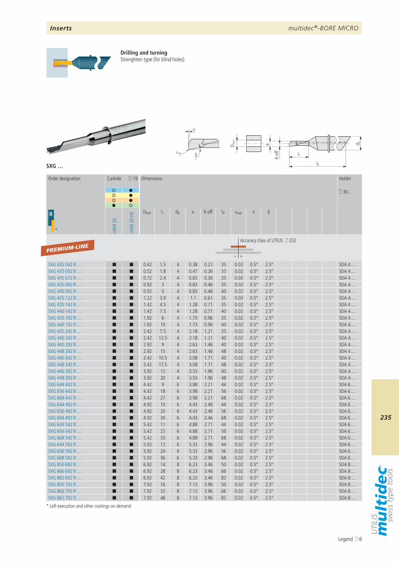
multidec®-BORE MICRO
235
SXG …
a d 0
l1
l0
D min
X-of
f
βr max
α
19
30…
R
* UHM
20
UHM
20
HX
Dmin l1 d0 a X-off l0 rmax α β
– +
SXG 435 042 R … ¢ ¢ 0.42 1.5 4 0.38 0.21 35 0.02 0.5° 2.5° SDA 4…SXG 435 052 R … ¢ ¢ 0.52 1.8 4 0.47 0.26 35 0.02 0.5° 2.5° SDA 4…SXG 435 072 R … ¢ ¢ 0.72 2.4 4 0.65 0.36 35 0.03 0.5° 2.5° SDA 4…SXG 435 092 R … ¢ ¢ 0.92 3 4 0.83 0.46 35 0.02 0.5° 2.5° SDA 4…SXG 440 092 R … ¢ ¢ 0.92 5 4 0.83 0.46 40 0.02 0.5° 2.5° SDA 4…SXG 435 122 R … ¢ ¢ 1.22 3.9 4 1.1 0.61 35 0.03 0.5° 2.5° SDA 4…SXG 435 142 R … ¢ ¢ 1.42 4.5 4 1.28 0.71 35 0.02 0.5° 2.5° SDA 4…SXG 440 142 R … ¢ ¢ 1.42 7.5 4 1.28 0.71 40 0.02 0.5° 2.5° SDA 4…SXG 435 192 R … ¢ ¢ 1.92 6 4 1.73 0.96 35 0.02 0.5° 2.5° SDA 4…SXG 440 192 R … ¢ ¢ 1.92 10 4 1.73 0.96 40 0.02 0.5° 2.5° SDA 4…SXG 435 242 R … ¢ ¢ 2.42 7.5 4 2.18 1.21 35 0.02 0.5° 2.5° SDA 4…SXG 440 242 R … ¢ ¢ 2.42 12.5 4 2.18 1.21 40 0.02 0.5° 2.5° SDA 4…SXG 440 292 R … ¢ ¢ 2.92 9 4 2.63 1.46 40 0.02 0.5° 2.5° SDA 4…SXG 448 292 R … ¢ ¢ 2.92 15 4 2.63 1.46 48 0.02 0.5° 2.5° SDA 4…SXG 440 342 R … ¢ ¢ 3.42 10.5 4 3.08 1.71 40 0.02 0.5° 2.5° SDA 4…SXG 448 342 R … ¢ ¢ 3.42 17.5 4 3.08 1.71 48 0.02 0.5° 2.5° SDA 4…SXG 440 392 R … ¢ ¢ 3.92 12 4 3.53 1.96 40 0.02 0.5° 2.5° SDA 4…SXG 448 392 R … ¢ ¢ 3.92 20 4 3.53 1.96 48 0.02 0.5° 2.5° SDA 4…SXG 644 442 R … ¢ ¢ 4.42 9 6 3.98 2.21 44 0.02 0.5° 2.5° SDA 6…SXG 656 442 R … ¢ ¢ 4.42 18 6 3.98 2.21 56 0.02 0.5° 2.5° SDA 6…SXG 668 442 R … ¢ ¢ 4.42 27 6 3.98 2.21 68 0.02 0.5° 2.5° SDA 6…SXG 644 492 R … ¢ ¢ 4.92 10 6 4.43 2.46 44 0.02 0.5° 2.5° SDA 6…SXG 656 492 R … ¢ ¢ 4.92 20 6 4.43 2.46 56 0.02 0.5° 2.5° SDA 6…SXG 668 492 R … ¢ ¢ 4.92 30 6 4.43 2.46 68 0.02 0.5° 2.5° SDA 6…SXG 644 542 R … ¢ ¢ 5.42 11 6 4.88 2.71 44 0.02 0.5° 2.5° SDA 6…SXG 656 542 R … ¢ ¢ 5.42 22 6 4.88 2.71 56 0.02 0.5° 2.5° SDA 6…SXG 668 542 R … ¢ ¢ 5.42 33 6 4.88 2.71 68 0.02 0.5° 2.5° SDA 6…SXG 644 592 R … ¢ ¢ 5.92 12 6 5.33 2.96 44 0.02 0.5° 2.5° SDA 6…SXG 656 592 R … ¢ ¢ 5.92 24 6 5.33 2.96 56 0.02 0.5° 2.5° SDA 6…SXG 668 592 R … ¢ ¢ 5.92 36 6 5.33 2.96 68 0.02 0.5° 2.5° SDA 6…SXG 850 692 R … ¢ ¢ 6.92 14 8 6.23 3.46 50 0.02 0.5° 2.5° SDA 8…SXG 866 692 R … ¢ ¢ 6.92 28 8 6.23 3.46 66 0.02 0.5° 2.5° SDA 8…SXG 882 692 R … ¢ ¢ 6.92 42 8 6.23 3.46 82 0.02 0.5° 2.5° SDA 8…SXG 850 792 R … ¢ ¢ 7.92 16 8 7.13 3.96 50 0.02 0.5° 2.5° SDA 8…SXG 866 792 R … ¢ ¢ 7.92 32 8 7.13 3.96 66 0.02 0.5° 2.5° SDA 8…SXG 882 792 R … ¢ ¢ 7.92 48 8 7.13 3.96 82 0.02 0.5° 2.5° SDA 8…
PREMIUM-LINE
Inserts
Drilling and turningStrenghten type (for blind holes)
* Left execution and other coatings on demand
Order designation Carbide Dimensions Holder
Accuracy class of UTILIS 232
Legend 6
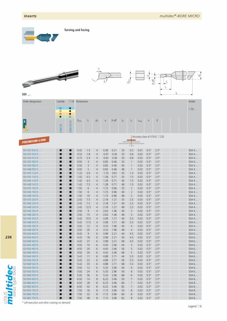
multidec®-BORE MICRO
236
a d 0
l1
l0
l2D min
X-of
frmax
α
β
SDI …
19
30…
R
* UHM
20
UHM
20
HX
Dmin l1 d0 a X-off l0 l2 rmax α β
– +
SDI 435 042 R … ¢ ¢ 0.42 1.5 4 0.38 0.21 35 0.5 0.01 0.5° 2.5° SDA 4…SDI 435 052 R … ¢ ¢ 0.52 1.8 4 0.47 0.26 35 0.6 0.02 0.5° 2.5° SDA 4…SDI 435 072 R … ¢ ¢ 0.72 2.4 4 0.65 0.36 35 0.8 0.02 0.5° 2.5° SDA 4…SDI 435 092 R … ¢ ¢ 0.92 3 4 0.83 0.46 35 1 0.02 0.5° 2.5° SDA 4…SDI 440 092 R … ¢ ¢ 0.92 3 4 0.83 0.46 40 1 0.02 0.5° 2.5° SDA 4…SDI 448 092 R … ¢ ¢ 0.92 5 4 0.83 0.46 48 1 0.02 0.5° 2.5° SDA 4…SDI 435 122 R … ¢ ¢ 1.22 3.9 4 1.10 0.61 35 1.3 0.02 0.5° 2.5° SDA 4…SDI 435 142 R … ¢ ¢ 1.42 4.5 4 1.28 0.71 35 1.5 0.02 0.5° 2.5° SDA 4…SDI 440 142 R … ¢ ¢ 1.42 4.5 4 1.28 0.71 40 1.5 0.02 0.5° 2.5° SDA 4…SDI 448 142 R … ¢ ¢ 1.42 7.5 4 1.28 0.71 48 1.5 0.02 0.5° 2.5° SDA 4…SDI 435 192 R … ¢ ¢ 1.92 6 4 1.73 0.96 35 2 0.03 0.5° 2.5° SDA 4…SDI 440 192 R … ¢ ¢ 1.92 6 4 1.73 0.96 40 2 0.02 0.5° 2.5° SDA 4…SDI 448 192 R … ¢ ¢ 1.92 10 4 1.73 0.96 48 2 0.02 0.5° 2.5° SDA 4…SDI 435 242 R … ¢ ¢ 2.42 7.5 4 2.18 1.21 35 2.5 0.03 0.5° 2.5° SDA 4…SDI 440 242 R … ¢ ¢ 2.42 7.5 4 2.18 1.21 40 2.5 0.02 0.5° 2.5° SDA 4…SDI 448 242 R … ¢ ¢ 2.42 12.5 4 2.18 1.21 48 2.5 0.02 0.5° 2.5° SDA 4…SDI 440 292 R … ¢ ¢ 2.92 9 4 2.63 1.46 40 3 0.02 0.5° 2.5° SDA 4…SDI 448 292 R … ¢ ¢ 2.92 15 4 2.63 1.46 48 3 0.02 0.5° 2.5° SDA 4…SDI 440 342 R … ¢ ¢ 3.42 10.5 4 3.08 1.71 40 3.5 0.02 0.5° 2.5° SDA 4…SDI 448 342 R … ¢ ¢ 3.42 17.5 4 3.08 1.71 48 3.5 0.02 0.5° 2.5° SDA 4…SDI 440 392 R … ¢ ¢ 3.92 12 4 3.53 1.96 40 4 0.02 0.5° 2.5° SDA 4…SDI 448 392 R … ¢ ¢ 3.92 20 4 3.53 1.96 48 4 0.02 0.5° 2.5° SDA 4…SDI 644 442 R … ¢ ¢ 4.42 9 6 3.98 2.21 44 4.5 0.02 0.5° 2.5° SDA 6…SDI 656 442 R … ¢ ¢ 4.42 18 6 3.98 2.21 56 4.5 0.02 0.5° 2.5° SDA 6…SDI 668 442 R … ¢ ¢ 4.42 27 6 3.98 2.21 68 4.5 0.02 0.5° 2.5° SDA 6…SDI 644 492 R … ¢ ¢ 4.92 10 6 4.43 2.46 44 5 0.02 0.5° 2.5° SDA 6…SDI 656 492 R … ¢ ¢ 4.92 20 6 4.43 2.46 56 5 0.02 0.5° 2.5° SDA 6…SDI 668 492 R … ¢ ¢ 4.92 30 6 4.43 2.46 68 5 0.02 0.5° 2.5° SDA 6…SDI 644 542 R … ¢ ¢ 5.42 11 6 4.88 2.71 44 5.5 0.02 0.5° 2.5° SDA 6…SDI 656 542 R … ¢ ¢ 5.42 22 6 4.88 2.71 56 5.5 0.02 0.5° 2.5° SDA 6…SDI 668 542 R … ¢ ¢ 5.42 33 6 4.88 2.71 68 5.5 0.02 0.5° 2.5° SDA 6…SDI 644 592 R … ¢ ¢ 5.92 12 6 5.33 2.96 44 6 0.02 0.5° 2.5° SDA 6…SDI 656 592 R … ¢ ¢ 5.92 24 6 5.33 2.96 56 6 0.02 0.5° 2.5° SDA 6…SDI 668 592 R … ¢ ¢ 5.92 36 6 5.33 2.96 68 6 0.02 0.5° 2.5° SDA 6…SDI 850 692 R … ¢ ¢ 6.92 14 8 6.23 3.46 50 7 0.02 0.5° 2.5° SDA 8…SDI 866 692 R … ¢ ¢ 6.92 28 8 6.23 3.46 66 7 0.02 0.5° 2.5° SDA 8…SDI 882 692 R … ¢ ¢ 6.92 42 8 6.23 3.46 82 7 0.02 0.5° 2.5° SDA 8…SDI 850 792 R … ¢ ¢ 7.92 16 8 7.13 3.96 50 8 0.02 0.5° 2.5° SDA 8…SDI 866 792 R … ¢ ¢ 7.92 32 8 7.13 3.96 66 8 0.02 0.5° 2.5° SDA 8…SDI 882 792 R … ¢ ¢ 7.92 48 8 7.13 3.96 82 8 0.02 0.5° 2.5° SDA 8…
PREMIUM-LINE
Turning and facing
* Left execution and other coatings on demand
Order designation Carbide Dimensions Holder
Accuracy class of UTILIS 232
Inserts
Legend 6

multidec®-BORE MICRO
237
SXI …
a d 0
l1
l0
D min
X-of
f
βr max
α
19
30…
R
* UHM
20
UHM
20
HX
Dmin l1 d0 a X-off l0 rmax α β
– +
SXI 435 042 R … ¢ ¢ 0.42 1.5 4 0.38 0.21 35 0.02 0.5° 2.5° SDA 4…SXI 435 052 R … ¢ ¢ 0.52 1.8 4 0.47 0.26 35 0.02 0.5° 2.5° SDA 4…SXI 435 072 R … ¢ ¢ 0.72 2.4 4 0.65 0.36 35 0.02 0.5° 2.5° SDA 4…SXI 435 092 R … ¢ ¢ 0.92 3 4 0.83 0.46 35 0.02 0.5° 2.5° SDA 4…SXI 440 092 R … ¢ ¢ 0.92 5 4 0.83 0.46 40 0.02 0.5° 2.5° SDA 4…SXI 435 122 R … ¢ ¢ 1.22 3.9 4 1.1 0.61 35 0.02 0.5° 2.5° SDA 4…SXI 435 142 R … ¢ ¢ 1.42 4.5 4 1.28 0.71 35 0.02 0.5° 2.5° SDA 4…SXI 440 142 R … ¢ ¢ 1.42 7.5 4 1.28 0.71 40 0.02 0.5° 2.5° SDA 4…SXI 435 192 R … ¢ ¢ 1.92 6 4 1.73 0.96 35 0.02 0.5° 2.5° SDA 4…SXI 440 192 R … ¢ ¢ 1.92 10 4 1.73 0.96 40 0.02 0.5° 2.5° SDA 4…SXI 435 242 R … ¢ ¢ 2.42 7.5 4 2.18 1.21 35 0.02 0.5° 2.5° SDA 4…SXI 440 242 R … ¢ ¢ 2.42 12.5 4 2.18 1.21 40 0.02 0.5° 2.5° SDA 4…SXI 440 292 R … ¢ ¢ 2.92 9 4 2.63 1.46 40 0.02 0.5° 2.5° SDA 4…SXI 448 292 R … ¢ ¢ 2.92 15 4 2.63 1.46 48 0.02 0.5° 2.5° SDA 4…SXI 440 342 R … ¢ ¢ 3.42 10.5 4 3.08 1.71 40 0.02 0.5° 2.5° SDA 4…SXI 448 342 R … ¢ ¢ 3.42 17.5 4 3.08 1.71 48 0.02 0.5° 2.5° SDA 4…SXI 440 392 R … ¢ ¢ 3.92 12 4 3.53 1.96 40 0.02 0.5° 2.5° SDA 4…SXI 448 392 R … ¢ ¢ 3.92 20 4 3.53 1.96 48 0.02 0.5° 2.5° SDA 4…SXI 644 442 R … ¢ ¢ 4.42 9 6 3.98 2.21 44 0.02 0.5° 2.5° SDA 6…SXI 656 442 R … ¢ ¢ 4.42 18 6 3.98 2.21 56 0.02 0.5° 2.5° SDA 6…SXI 668 442 R … ¢ ¢ 4.42 27 6 3.98 2.21 68 0.02 0.5° 2.5° SDA 6…SXI 644 492 R … ¢ ¢ 4.92 10 6 4.43 2.46 44 0.02 0.5° 2.5° SDA 6…SXI 656 492 R … ¢ ¢ 4.92 20 6 4.43 2.46 56 0.02 0.5° 2.5° SDA 6…SXI 668 492 R … ¢ ¢ 4.92 30 6 4.43 2.46 68 0.02 0.5° 2.5° SDA 6…SXI 644 542 R … ¢ ¢ 5.42 11 6 4.88 2.71 44 0.02 0.5° 2.5° SDA 6…SXI 656 542 R … ¢ ¢ 5.42 22 6 4.88 2.71 56 0.02 0.5° 2.5° SDA 6…SXI 668 542 R … ¢ ¢ 5.42 33 6 4.88 2.71 68 0.02 0.5° 2.5° SDA 6…SXI 644 592 R … ¢ ¢ 5.92 12 6 5.33 2.96 44 0.02 0.5° 2.5° SDA 6…SXI 656 592 R … ¢ ¢ 5.92 24 6 5.33 2.96 56 0.02 0.5° 2.5° SDA 6…SXI 668 592 R … ¢ ¢ 5.92 36 6 5.33 2.96 68 0.02 0.5° 2.5° SDA 6…SXI 850 692 R … ¢ ¢ 6.92 14 8 6.23 3.46 50 0.02 0.5° 2.5° SDA 8…SXI 866 692 R … ¢ ¢ 6.92 28 8 6.23 3.46 66 0.02 0.5° 2.5° SDA 8…SXI 882 692 R … ¢ ¢ 6.92 42 8 6.23 3.46 82 0.02 0.5° 2.5° SDA 8…SXI 850 792 R … ¢ ¢ 7.92 16 8 7.13 3.96 50 0.02 0.5° 2.5° SDA 8…SXI 866 792 R … ¢ ¢ 7.92 32 8 7.13 3.96 66 0.02 0.5° 2.5° SDA 8…SXI 882 792 R … ¢ ¢ 7.92 48 8 7.13 3.96 82 0.02 0.5° 2.5° SDA 8…
PREMIUM-LINE
Turning and facingStrenghten type (for blind holes)
* Left execution and other coatings on demand
Order designation Carbide Dimensions Holder
Accuracy class of UTILIS 232
Inserts
Legend 6
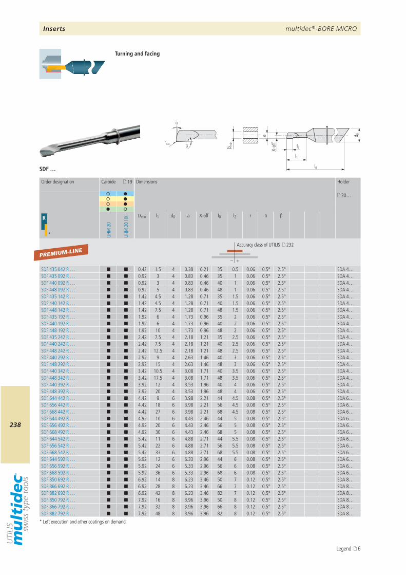
multidec®-BORE MICRO
238
SDF …
19
30…
R
* UHM
20
UHM
20
HX
Dmin l1 d0 a X-off l0 l2 r α β
– +
SDF 435 042 R … ¢ ¢ 0.42 1.5 4 0.38 0.21 35 0.5 0.06 0.5° 2.5° SDA 4…SDF 435 092 R … ¢ ¢ 0.92 3 4 0.83 0.46 35 1 0.06 0.5° 2.5° SDA 4…SDF 440 092 R … ¢ ¢ 0.92 3 4 0.83 0.46 40 1 0.06 0.5° 2.5° SDA 4…SDF 448 092 R … ¢ ¢ 0.92 5 4 0.83 0.46 48 1 0.06 0.5° 2.5° SDA 4…SDF 435 142 R … ¢ ¢ 1.42 4.5 4 1.28 0.71 35 1.5 0.06 0.5° 2.5° SDA 4…SDF 440 142 R … ¢ ¢ 1.42 4.5 4 1.28 0.71 40 1.5 0.06 0.5° 2.5° SDA 4…SDF 448 142 R … ¢ ¢ 1.42 7.5 4 1.28 0.71 48 1.5 0.06 0.5° 2.5° SDA 4…SDF 435 192 R … ¢ ¢ 1.92 6 4 1.73 0.96 35 2 0.06 0.5° 2.5° SDA 4…SDF 440 192 R … ¢ ¢ 1.92 6 4 1.73 0.96 40 2 0.06 0.5° 2.5° SDA 4…SDF 448 192 R … ¢ ¢ 1.92 10 4 1.73 0.96 48 2 0.06 0.5° 2.5° SDA 4…SDF 435 242 R … ¢ ¢ 2.42 7.5 4 2.18 1.21 35 2.5 0.06 0.5° 2.5° SDA 4…SDF 440 242 R … ¢ ¢ 2.42 7.5 4 2.18 1.21 40 2.5 0.06 0.5° 2.5° SDA 4…SDF 448 242 R … ¢ ¢ 2.42 12.5 4 2.18 1.21 48 2.5 0.06 0.5° 2.5° SDA 4…SDF 440 292 R … ¢ ¢ 2.92 9 4 2.63 1.46 40 3 0.06 0.5° 2.5° SDA 4…SDF 448 292 R … ¢ ¢ 2.92 15 4 2.63 1.46 48 3 0.06 0.5° 2.5° SDA 4…SDF 440 342 R … ¢ ¢ 3.42 10.5 4 3.08 1.71 40 3.5 0.06 0.5° 2.5° SDA 4…SDF 448 342 R … ¢ ¢ 3.42 17.5 4 3.08 1.71 48 3.5 0.06 0.5° 2.5° SDA 4…SDF 440 392 R … ¢ ¢ 3.92 12 4 3.53 1.96 40 4 0.06 0.5° 2.5° SDA 4…SDF 448 392 R … ¢ ¢ 3.92 20 4 3.53 1.96 48 4 0.06 0.5° 2.5° SDA 4…SDF 644 442 R … ¢ ¢ 4.42 9 6 3.98 2.21 44 4.5 0.08 0.5° 2.5° SDA 6…SDF 656 442 R … ¢ ¢ 4.42 18 6 3.98 2.21 56 4.5 0.08 0.5° 2.5° SDA 6…SDF 668 442 R … ¢ ¢ 4.42 27 6 3.98 2.21 68 4.5 0.08 0.5° 2.5° SDA 6…SDF 644 492 R … ¢ ¢ 4.92 10 6 4.43 2.46 44 5 0.08 0.5° 2.5° SDA 6…SDF 656 492 R … ¢ ¢ 4.92 20 6 4.43 2.46 56 5 0.08 0.5° 2.5° SDA 6…SDF 668 492 R … ¢ ¢ 4.92 30 6 4.43 2.46 68 5 0.08 0.5° 2.5° SDA 6…SDF 644 542 R … ¢ ¢ 5.42 11 6 4.88 2.71 44 5.5 0.08 0.5° 2.5° SDA 6…SDF 656 542 R … ¢ ¢ 5.42 22 6 4.88 2.71 56 5.5 0.08 0.5° 2.5° SDA 6…SDF 668 542 R … ¢ ¢ 5.42 33 6 4.88 2.71 68 5.5 0.08 0.5° 2.5° SDA 6…SDF 644 592 R … ¢ ¢ 5.92 12 6 5.33 2.96 44 6 0.08 0.5° 2.5° SDA 6…SDF 656 592 R … ¢ ¢ 5.92 24 6 5.33 2.96 56 6 0.08 0.5° 2.5° SDA 6…SDF 668 592 R … ¢ ¢ 5.92 36 6 5.33 2.96 68 6 0.08 0.5° 2.5° SDA 6…SDF 850 692 R … ¢ ¢ 6.92 14 8 6.23 3.46 50 7 0.12 0.5° 2.5° SDA 8…SDF 866 692 R … ¢ ¢ 6.92 28 8 6.23 3.46 66 7 0.12 0.5° 2.5° SDA 8…SDF 882 692 R … ¢ ¢ 6.92 42 8 6.23 3.46 82 7 0.12 0.5° 2.5° SDA 8…SDF 850 792 R … ¢ ¢ 7.92 16 8 3.96 3.96 50 8 0.12 0.5° 2.5° SDA 8…SDF 866 792 R … ¢ ¢ 7.92 32 8 3.96 3.96 66 8 0.12 0.5° 2.5° SDA 8…SDF 882 792 R … ¢ ¢ 7.92 48 8 3.96 3.96 82 8 0.12 0.5° 2.5° SDA 8…
PREMIUM-LINE
a d 0
l1
l0
l2D min
X-of
frmax
α
β
Turning and facing
* Left execution and other coatings on demand
Order designation Carbide Dimensions Holder
Accuracy class of UTILIS 232
Inserts
Legend 6
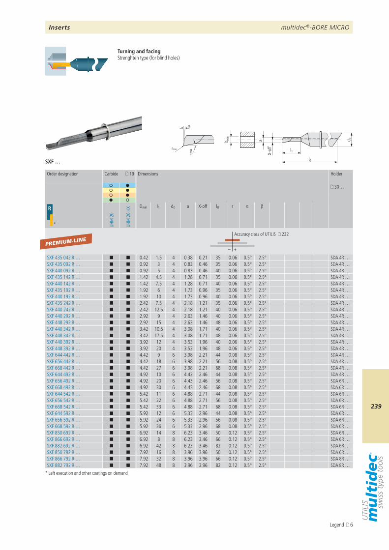
multidec®-BORE MICRO
239
SXF …
a d 0
l1
l0
D min
X-of
f
βr max
α
19
30…
R
* UHM
20
UHM
20
HX
Dmin l1 d0 a X-off l0 r α β
– +
SXF 435 042 R … ¢ ¢ 0.42 1.5 4 0.38 0.21 35 0.06 0.5° 2.5° SDA 4R …SXF 435 092 R … ¢ ¢ 0.92 3 4 0.83 0.46 35 0.06 0.5° 2.5° SDA 4R …SXF 440 092 R … ¢ ¢ 0.92 5 4 0.83 0.46 40 0.06 0.5° 2.5° SDA 4R …SXF 435 142 R … ¢ ¢ 1.42 4.5 4 1.28 0.71 35 0.06 0.5° 2.5° SDA 4R …SXF 440 142 R … ¢ ¢ 1.42 7.5 4 1.28 0.71 40 0.06 0.5° 2.5° SDA 4R …SXF 435 192 R … ¢ ¢ 1.92 6 4 1.73 0.96 35 0.06 0.5° 2.5° SDA 4R …SXF 440 192 R … ¢ ¢ 1.92 10 4 1.73 0.96 40 0.06 0.5° 2.5° SDA 4R …SXF 435 242 R … ¢ ¢ 2.42 7.5 4 2.18 1.21 35 0.06 0.5° 2.5° SDA 4R …SXF 440 242 R … ¢ ¢ 2.42 12.5 4 2.18 1.21 40 0.06 0.5° 2.5° SDA 4R …SXF 440 292 R … ¢ ¢ 2.92 9 4 2.63 1.46 40 0.06 0.5° 2.5° SDA 4R …SXF 448 292 R … ¢ ¢ 2.92 15 4 2.63 1.46 48 0.06 0.5° 2.5° SDA 4R …SXF 440 342 R … ¢ ¢ 3.42 10.5 4 3.08 1.71 40 0.06 0.5° 2.5° SDA 4R …SXF 448 342 R … ¢ ¢ 3.42 17.5 4 3.08 1.71 48 0.06 0.5° 2.5° SDA 4R …SXF 440 392 R … ¢ ¢ 3.92 12 4 3.53 1.96 40 0.06 0.5° 2.5° SDA 4R …SXF 448 392 R … ¢ ¢ 3.92 20 4 3.53 1.96 48 0.06 0.5° 2.5° SDA 4R …SXF 644 442 R … ¢ ¢ 4.42 9 6 3.98 2.21 44 0.08 0.5° 2.5° SDA 4R …SXF 656 442 R … ¢ ¢ 4.42 18 6 3.98 2.21 56 0.08 0.5° 2.5° SDA 4R …SXF 668 442 R … ¢ ¢ 4.42 27 6 3.98 2.21 68 0.08 0.5° 2.5° SDA 4R …SXF 644 492 R … ¢ ¢ 4.92 10 6 4.43 2.46 44 0.08 0.5° 2.5° SDA 4R …SXF 656 492 R … ¢ ¢ 4.92 20 6 4.43 2.46 56 0.08 0.5° 2.5° SDA 6R …SXF 668 492 R … ¢ ¢ 4.92 30 6 4.43 2.46 68 0.08 0.5° 2.5° SDA 6R …SXF 644 542 R … ¢ ¢ 5.42 11 6 4.88 2.71 44 0.08 0.5° 2.5° SDA 6R …SXF 656 542 R … ¢ ¢ 5.42 22 6 4.88 2.71 56 0.08 0.5° 2.5° SDA 6R …SXF 668 542 R … ¢ ¢ 5.42 33 6 4.88 2.71 68 0.08 0.5° 2.5° SDA 6R …SXF 644 592 R … ¢ ¢ 5.92 12 6 5.33 2.96 44 0.08 0.5° 2.5° SDA 6R …SXF 656 592 R … ¢ ¢ 5.92 24 6 5.33 2.96 56 0.08 0.5° 2.5° SDA 6R …SXF 668 592 R … ¢ ¢ 5.92 36 6 5.33 2.96 68 0.08 0.5° 2.5° SDA 6R …SXF 850 692 R … ¢ ¢ 6.92 14 8 6.23 3.46 50 0.12 0.5° 2.5° SDA 6R …SXF 866 692 R … ¢ ¢ 6.92 8 8 6.23 3.46 66 0.12 0.5° 2.5° SDA 6R …SXF 882 692 R … ¢ ¢ 6.92 42 8 6.23 3.46 82 0.12 0.5° 2.5° SDA 6R …SXF 850 792 R … ¢ ¢ 7.92 16 8 3.96 3.96 50 0.12 0.5° 2.5° SDA 6R …SXF 866 792 R … ¢ ¢ 7.92 32 8 3.96 3.96 66 0.12 0.5° 2.5° SDA 8R …SXF 882 792 R … ¢ ¢ 7.92 48 8 3.96 3.96 82 0.12 0.5° 2.5° SDA 8R …
PREMIUM-LINE
Turning and facingStrenghten type (for blind holes)
* Left execution and other coatings on demand
Order designation Carbide Dimensions Holder
Accuracy class of UTILIS 232
Inserts
Legend 6
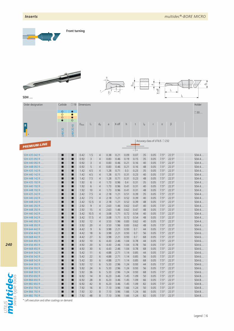
multidec®-BORE MICRO
240
a d 0
l1
l0
D min
X-of
f
βr ht
α
SDH …
19
30…
R
* UHM
20
UHM
20
HX
Dmin l1 d0 a X-off h t l0 r α β
– +
SDH 435 042 R … ¢ ¢ 0.42 1.5 4 0.38 0.21 0.09 0.07 35 0.05 7.5° 22.5° SDA 4…SDH 435 092 R … ¢ ¢ 0.92 3 4 0.83 0.46 0.19 0.15 35 0.05 7.5° 22.5° SDA 4…SDH 440 092 R … ¢ ¢ 0.92 3 4 0.83 0.46 0.21 0.16 40 0.05 7.5° 22.5° SDA 4…SDH 448 092 R … ¢ ¢ 0.92 5 4 0.83 0.46 0.21 0.16 48 0.05 7.5° 22.5° SDA 4…SDH 435 142 R … ¢ ¢ 1.42 4.5 4 1.28 0.71 0.3 0.23 35 0.05 7.5° 22.5° SDA 4…SDH 440 142 R … ¢ ¢ 1.42 4.5 4 1.28 0.71 0.31 0.23 40 0.05 7.5° 22.5° SDA 4…SDH 448 142 R … ¢ ¢ 1.42 7.5 4 1.28 0.71 0.31 0.23 48 0.05 7.5° 22.5° SDA 4…SDH 435 192 R … ¢ ¢ 1.92 6 4 1.73 0.96 0.4 0.31 35 0.05 7.5° 22.5° SDA 4…SDH 440 192 R … ¢ ¢ 1.92 6 4 1.73 0.96 0.41 0.31 40 0.05 7.5° 22.5° SDA 4…SDH 448 192 R … ¢ ¢ 1.92 10 4 1.73 0.96 0.41 0.31 48 0.05 7.5° 22.5° SDA 4…SDH 435 242 R … ¢ ¢ 2.42 7.5 4 2.18 1.21 0.51 0.39 35 0.05 7.5° 22.5° SDA 4…SDH 440 242 R … ¢ ¢ 2.42 7.5 4 2.18 1.21 0.52 0.39 40 0.05 7.5° 22.5° SDA 4…SDH 448 242 R … ¢ ¢ 2.42 12.5 4 2.18 1.21 0.52 0.39 48 0.05 7.5° 22.5° SDA 4…SDH 440 292 R … ¢ ¢ 2.92 9 4 2.63 1.46 0.62 0.47 40 0.05 7.5° 22.5° SDA 4…SDH 448 292 R … ¢ ¢ 2.92 15 4 2.63 1.46 0.62 0.47 48 0.05 7.5° 22.5° SDA 4…SDH 440 342 R … ¢ ¢ 3.42 10.5 4 3.08 1.71 0.72 0.54 40 0.05 7.5° 22.5° SDA 4…SDH 448 342 R … ¢ ¢ 3.42 17.5 4 3.08 1.71 0.72 0.54 48 0.05 7.5° 22.5° SDA 4…SDH 440 392 R … ¢ ¢ 3.92 12 4 3.53 1.96 0.83 0.62 40 0.05 7.5° 22.5° SDA 4…SDH 448 392 R … ¢ ¢ 3.92 20 4 3.53 1.96 0.83 0.62 48 0.05 7.5° 22.5° SDA 4…SDH 644 442 R … ¢ ¢ 4.42 9 6 3.98 2.21 0.93 0.7 44 0.05 7.5° 22.5° SDA 6…SDH 656 442 R … ¢ ¢ 4.42 18 6 3.98 2.21 0.93 0.7 56 0.05 7.5° 22.5° SDA 6…SDH 668 442 R … ¢ ¢ 4.42 27 6 3.98 2.21 0.93 0.7 68 0.05 7.5° 22.5° SDA 6…SDH 644 492 R … ¢ ¢ 4.92 10 6 4.43 2.46 1.04 0.78 44 0.05 7.5° 22.5° SDA 6…SDH 656 492 R … ¢ ¢ 4.92 20 6 4.43 2.46 1.04 0.78 56 0.05 7.5° 22.5° SDA 6…SDH 668 492 R … ¢ ¢ 4.92 30 6 4.43 2.46 1.04 0.78 68 0.05 7.5° 22.5° SDA 6…SDH 644 542 R … ¢ ¢ 5.42 11 6 4.88 2.71 1.14 0.85 44 0.05 7.5° 22.5° SDA 6…SDH 656 542 R … ¢ ¢ 5.42 22 6 4.88 2.71 1.14 0.85 56 0.05 7.5° 22.5° SDA 6…SDH 668 542 R … ¢ ¢ 5.42 33 6 4.88 2.71 1.14 0.85 68 0.05 7.5° 22.5° SDA 6…SDH 644 592 R … ¢ ¢ 5.92 12 6 5.33 2.96 1.24 0.93 44 0.05 7.5° 22.5° SDA 6…SDH 656 592 R … ¢ ¢ 5.92 24 6 5.33 2.96 1.24 0.93 56 0.05 7.5° 22.5° SDA 6…SDH 668 592 R … ¢ ¢ 5.92 36 6 5.33 2.96 1.24 0.93 68 0.05 7.5° 22.5° SDA 6…SDH 850 692 R … ¢ ¢ 6.92 14 8 6.23 3.46 1.45 1.09 50 0.05 7.5° 22.5° SDA 8…SDH 866 692 R … ¢ ¢ 6.92 28 8 6.23 3.46 1.45 1.09 66 0.05 7.5° 22.5° SDA 8…SDH 882 692 R … ¢ ¢ 6.92 42 8 6.23 3.46 1.45 1.09 82 0.05 7.5° 22.5° SDA 8…SDH 850 792 R … ¢ ¢ 7.92 16 8 7.13 3.96 1.66 1.24 50 0.05 7.5° 22.5° SDA 8…SDH 866 792 R … ¢ ¢ 7.92 32 8 7.13 3.96 1.66 1.24 66 0.05 7.5° 22.5° SDA 8…SDH 882 792 R … ¢ ¢ 7.92 48 8 7.13 3.96 1.66 1.24 82 0.05 7.5° 22.5° SDA 8…
PREMIUM-LINE
Front turning
* Left execution and other coatings on demand
Order designation Carbide Dimensions Holder
Accuracy class of UTILIS 232
Inserts
Legend 6
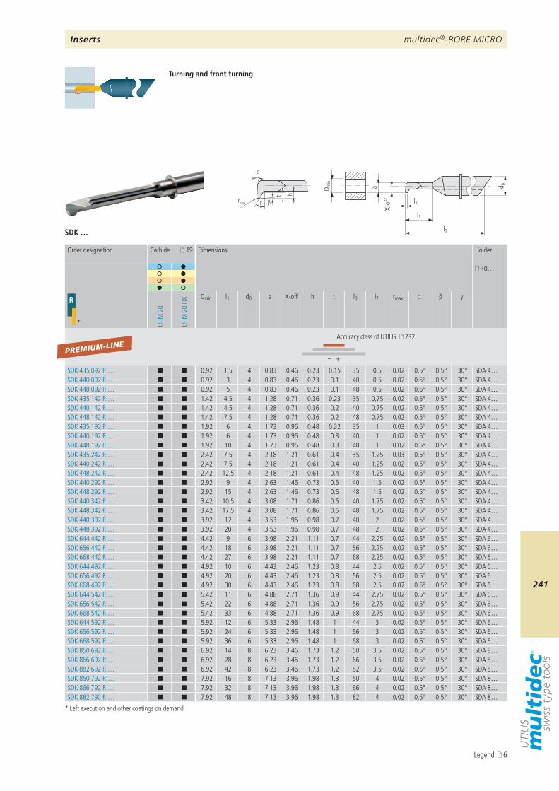
multidec®-BORE MICRO
241
a d 0
l1
l0
l2
D min
X-of
f
βrmax
t h
α
γ
SDK …
19
30…
R
* UHM
20
UHM
20
HX
Dmin l1 d0 a X-off h t l0 l2 rmax α β γ
– +
SDK 435 092 R … ¢ ¢ 0.92 1.5 4 0.83 0.46 0.23 0.15 35 0.5 0.02 0.5° 0.5° 30° SDA 4…SDK 440 092 R … ¢ ¢ 0.92 3 4 0.83 0.46 0.23 0.1 40 0.5 0.02 0.5° 0.5° 30° SDA 4…SDK 448 092 R … ¢ ¢ 0.92 5 4 0.83 0.46 0.23 0.1 48 0.5 0.02 0.5° 0.5° 30° SDA 4…SDK 435 142 R … ¢ ¢ 1.42 4.5 4 1.28 0.71 0.36 0.23 35 0.75 0.02 0.5° 0.5° 30° SDA 4…SDK 440 142 R … ¢ ¢ 1.42 4.5 4 1.28 0.71 0.36 0.2 40 0.75 0.02 0.5° 0.5° 30° SDA 4…SDK 448 142 R … ¢ ¢ 1.42 7.5 4 1.28 0.71 0.36 0.2 48 0.75 0.02 0.5° 0.5° 30° SDA 4…SDK 435 192 R … ¢ ¢ 1.92 6 4 1.73 0.96 0.48 0.32 35 1 0.03 0.5° 0.5° 30° SDA 4…SDK 440 192 R … ¢ ¢ 1.92 6 4 1.73 0.96 0.48 0.3 40 1 0.02 0.5° 0.5° 30° SDA 4…SDK 448 192 R … ¢ ¢ 1.92 10 4 1.73 0.96 0.48 0.3 48 1 0.02 0.5° 0.5° 30° SDA 4…SDK 435 242 R … ¢ ¢ 2.42 7.5 4 2.18 1.21 0.61 0.4 35 1.25 0.03 0.5° 0.5° 30° SDA 4…SDK 440 242 R … ¢ ¢ 2.42 7.5 4 2.18 1.21 0.61 0.4 40 1.25 0.02 0.5° 0.5° 30° SDA 4…SDK 448 242 R … ¢ ¢ 2.42 12.5 4 2.18 1.21 0.61 0.4 48 1.25 0.02 0.5° 0.5° 30° SDA 4…SDK 440 292 R … ¢ ¢ 2.92 9 4 2.63 1.46 0.73 0.5 40 1.5 0.02 0.5° 0.5° 30° SDA 4…SDK 448 292 R … ¢ ¢ 2.92 15 4 2.63 1.46 0.73 0.5 48 1.5 0.02 0.5° 0.5° 30° SDA 4…SDK 440 342 R … ¢ ¢ 3.42 10.5 4 3.08 1.71 0.86 0.6 40 1.75 0.02 0.5° 0.5° 30° SDA 4…SDK 448 342 R … ¢ ¢ 3.42 17.5 4 3.08 1.71 0.86 0.6 48 1.75 0.02 0.5° 0.5° 30° SDA 4…SDK 440 392 R … ¢ ¢ 3.92 12 4 3.53 1.96 0.98 0.7 40 2 0.02 0.5° 0.5° 30° SDA 4…SDK 448 392 R … ¢ ¢ 3.92 20 4 3.53 1.96 0.98 0.7 48 2 0.02 0.5° 0.5° 30° SDA 4…SDK 644 442 R … ¢ ¢ 4.42 9 6 3.98 2.21 1.11 0.7 44 2.25 0.02 0.5° 0.5° 30° SDA 6…SDK 656 442 R … ¢ ¢ 4.42 18 6 3.98 2.21 1.11 0.7 56 2.25 0.02 0.5° 0.5° 30° SDA 6…SDK 668 442 R … ¢ ¢ 4.42 27 6 3.98 2.21 1.11 0.7 68 2.25 0.02 0.5° 0.5° 30° SDA 6…SDK 644 492 R … ¢ ¢ 4.92 10 6 4.43 2.46 1.23 0.8 44 2.5 0.02 0.5° 0.5° 30° SDA 6…SDK 656 492 R … ¢ ¢ 4.92 20 6 4.43 2.46 1.23 0.8 56 2.5 0.02 0.5° 0.5° 30° SDA 6…SDK 668 492 R … ¢ ¢ 4.92 30 6 4.43 2.46 1.23 0.8 68 2.5 0.02 0.5° 0.5° 30° SDA 6…SDK 644 542 R … ¢ ¢ 5.42 11 6 4.88 2.71 1.36 0.9 44 2.75 0.02 0.5° 0.5° 30° SDA 6…SDK 656 542 R … ¢ ¢ 5.42 22 6 4.88 2.71 1.36 0.9 56 2.75 0.02 0.5° 0.5° 30° SDA 6…SDK 668 542 R … ¢ ¢ 5.42 33 6 4.88 2.71 1.36 0.9 68 2.75 0.02 0.5° 0.5° 30° SDA 6…SDK 644 592 R … ¢ ¢ 5.92 12 6 5.33 2.96 1.48 1 44 3 0.02 0.5° 0.5° 30° SDA 6…SDK 656 592 R … ¢ ¢ 5.92 24 6 5.33 2.96 1.48 1 56 3 0.02 0.5° 0.5° 30° SDA 6…SDK 668 592 R … ¢ ¢ 5.92 36 6 5.33 2.96 1.48 1 68 3 0.02 0.5° 0.5° 30° SDA 6…SDK 850 692 R … ¢ ¢ 6.92 14 8 6.23 3.46 1.73 1.2 50 3.5 0.02 0.5° 0.5° 30° SDA 8…SDK 866 692 R … ¢ ¢ 6.92 28 8 6.23 3.46 1.73 1.2 66 3.5 0.02 0.5° 0.5° 30° SDA 8…SDK 882 692 R … ¢ ¢ 6.92 42 8 6.23 3.46 1.73 1.2 82 3.5 0.02 0.5° 0.5° 30° SDA 8…SDK 850 792 R … ¢ ¢ 7.92 16 8 7.13 3.96 1.98 1.3 50 4 0.02 0.5° 0.5° 30° SDA 8…SDK 866 792 R … ¢ ¢ 7.92 32 8 7.13 3.96 1.98 1.3 66 4 0.02 0.5° 0.5° 30° SDA 8…SDK 882 792 R … ¢ ¢ 7.92 48 8 7.13 3.96 1.98 1.3 82 4 0.02 0.5° 0.5° 30° SDA 8…
PREMIUM-LINE
Turning and front turning
* Left execution and other coatings on demand
Order designation Carbide Dimensions Holder
Accuracy class of UTILIS 232
Inserts
Legend 6
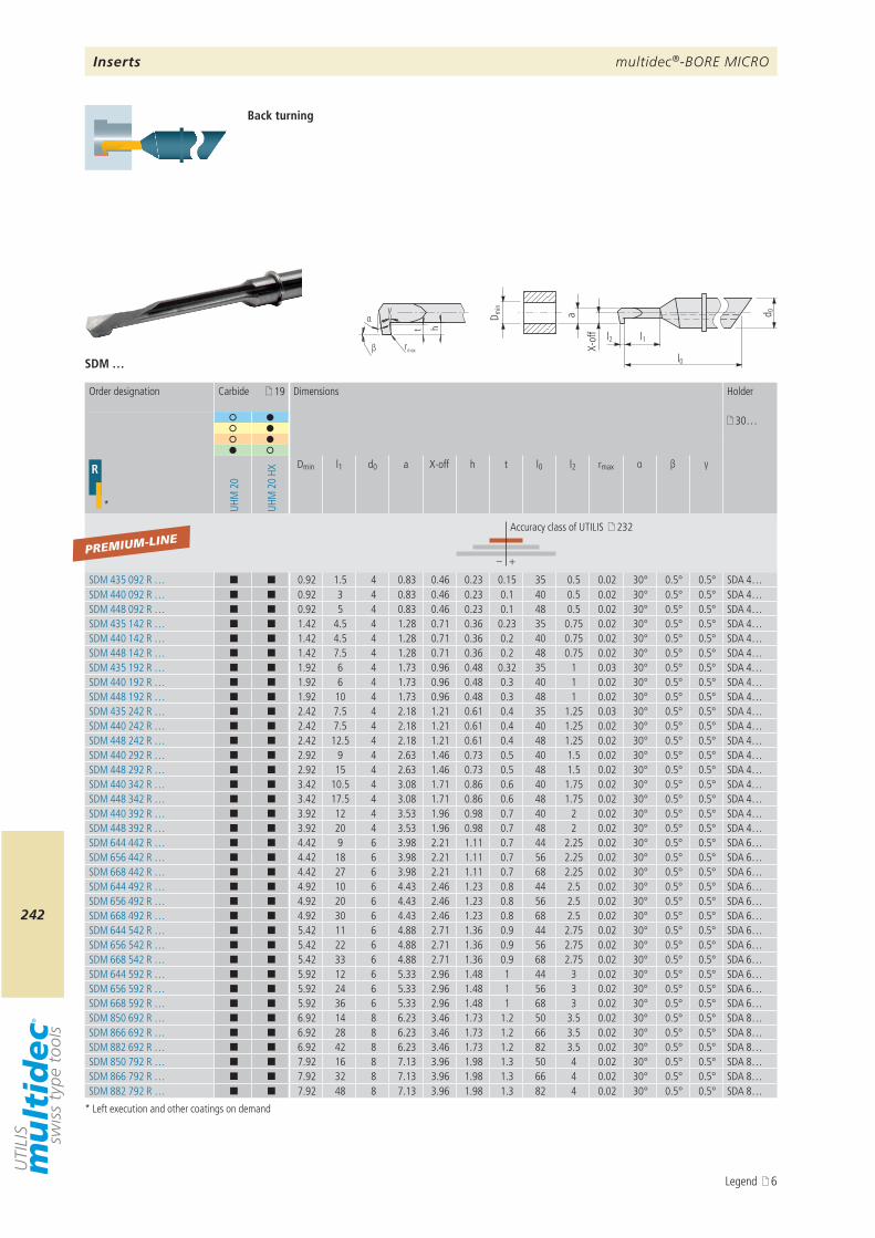
multidec®-BORE MICRO
242
a d 0
l1
l0
l2
D min
X-of
f
β rmax
t h
αγ
SDM …
19
30…
R
* UHM
20
UHM
20
HX
Dmin l1 d0 a X-off h t l0 l2 rmax α β γ
– +
SDM 435 092 R … ¢ ¢ 0.92 1.5 4 0.83 0.46 0.23 0.15 35 0.5 0.02 30° 0.5° 0.5° SDA 4…SDM 440 092 R … ¢ ¢ 0.92 3 4 0.83 0.46 0.23 0.1 40 0.5 0.02 30° 0.5° 0.5° SDA 4…SDM 448 092 R … ¢ ¢ 0.92 5 4 0.83 0.46 0.23 0.1 48 0.5 0.02 30° 0.5° 0.5° SDA 4…SDM 435 142 R … ¢ ¢ 1.42 4.5 4 1.28 0.71 0.36 0.23 35 0.75 0.02 30° 0.5° 0.5° SDA 4…SDM 440 142 R … ¢ ¢ 1.42 4.5 4 1.28 0.71 0.36 0.2 40 0.75 0.02 30° 0.5° 0.5° SDA 4…SDM 448 142 R … ¢ ¢ 1.42 7.5 4 1.28 0.71 0.36 0.2 48 0.75 0.02 30° 0.5° 0.5° SDA 4…SDM 435 192 R … ¢ ¢ 1.92 6 4 1.73 0.96 0.48 0.32 35 1 0.03 30° 0.5° 0.5° SDA 4…SDM 440 192 R … ¢ ¢ 1.92 6 4 1.73 0.96 0.48 0.3 40 1 0.02 30° 0.5° 0.5° SDA 4…SDM 448 192 R … ¢ ¢ 1.92 10 4 1.73 0.96 0.48 0.3 48 1 0.02 30° 0.5° 0.5° SDA 4…SDM 435 242 R … ¢ ¢ 2.42 7.5 4 2.18 1.21 0.61 0.4 35 1.25 0.03 30° 0.5° 0.5° SDA 4…SDM 440 242 R … ¢ ¢ 2.42 7.5 4 2.18 1.21 0.61 0.4 40 1.25 0.02 30° 0.5° 0.5° SDA 4…SDM 448 242 R … ¢ ¢ 2.42 12.5 4 2.18 1.21 0.61 0.4 48 1.25 0.02 30° 0.5° 0.5° SDA 4…SDM 440 292 R … ¢ ¢ 2.92 9 4 2.63 1.46 0.73 0.5 40 1.5 0.02 30° 0.5° 0.5° SDA 4…SDM 448 292 R … ¢ ¢ 2.92 15 4 2.63 1.46 0.73 0.5 48 1.5 0.02 30° 0.5° 0.5° SDA 4…SDM 440 342 R … ¢ ¢ 3.42 10.5 4 3.08 1.71 0.86 0.6 40 1.75 0.02 30° 0.5° 0.5° SDA 4…SDM 448 342 R … ¢ ¢ 3.42 17.5 4 3.08 1.71 0.86 0.6 48 1.75 0.02 30° 0.5° 0.5° SDA 4…SDM 440 392 R … ¢ ¢ 3.92 12 4 3.53 1.96 0.98 0.7 40 2 0.02 30° 0.5° 0.5° SDA 4…SDM 448 392 R … ¢ ¢ 3.92 20 4 3.53 1.96 0.98 0.7 48 2 0.02 30° 0.5° 0.5° SDA 4…SDM 644 442 R … ¢ ¢ 4.42 9 6 3.98 2.21 1.11 0.7 44 2.25 0.02 30° 0.5° 0.5° SDA 6…SDM 656 442 R … ¢ ¢ 4.42 18 6 3.98 2.21 1.11 0.7 56 2.25 0.02 30° 0.5° 0.5° SDA 6…SDM 668 442 R … ¢ ¢ 4.42 27 6 3.98 2.21 1.11 0.7 68 2.25 0.02 30° 0.5° 0.5° SDA 6…SDM 644 492 R … ¢ ¢ 4.92 10 6 4.43 2.46 1.23 0.8 44 2.5 0.02 30° 0.5° 0.5° SDA 6…SDM 656 492 R … ¢ ¢ 4.92 20 6 4.43 2.46 1.23 0.8 56 2.5 0.02 30° 0.5° 0.5° SDA 6…SDM 668 492 R … ¢ ¢ 4.92 30 6 4.43 2.46 1.23 0.8 68 2.5 0.02 30° 0.5° 0.5° SDA 6…SDM 644 542 R … ¢ ¢ 5.42 11 6 4.88 2.71 1.36 0.9 44 2.75 0.02 30° 0.5° 0.5° SDA 6…SDM 656 542 R … ¢ ¢ 5.42 22 6 4.88 2.71 1.36 0.9 56 2.75 0.02 30° 0.5° 0.5° SDA 6…SDM 668 542 R … ¢ ¢ 5.42 33 6 4.88 2.71 1.36 0.9 68 2.75 0.02 30° 0.5° 0.5° SDA 6…SDM 644 592 R … ¢ ¢ 5.92 12 6 5.33 2.96 1.48 1 44 3 0.02 30° 0.5° 0.5° SDA 6…SDM 656 592 R … ¢ ¢ 5.92 24 6 5.33 2.96 1.48 1 56 3 0.02 30° 0.5° 0.5° SDA 6…SDM 668 592 R … ¢ ¢ 5.92 36 6 5.33 2.96 1.48 1 68 3 0.02 30° 0.5° 0.5° SDA 6…SDM 850 692 R … ¢ ¢ 6.92 14 8 6.23 3.46 1.73 1.2 50 3.5 0.02 30° 0.5° 0.5° SDA 8…SDM 866 692 R … ¢ ¢ 6.92 28 8 6.23 3.46 1.73 1.2 66 3.5 0.02 30° 0.5° 0.5° SDA 8…SDM 882 692 R … ¢ ¢ 6.92 42 8 6.23 3.46 1.73 1.2 82 3.5 0.02 30° 0.5° 0.5° SDA 8…SDM 850 792 R … ¢ ¢ 7.92 16 8 7.13 3.96 1.98 1.3 50 4 0.02 30° 0.5° 0.5° SDA 8…SDM 866 792 R … ¢ ¢ 7.92 32 8 7.13 3.96 1.98 1.3 66 4 0.02 30° 0.5° 0.5° SDA 8…SDM 882 792 R … ¢ ¢ 7.92 48 8 7.13 3.96 1.98 1.3 82 4 0.02 30° 0.5° 0.5° SDA 8…
PREMIUM-LINE
Back turning
* Left execution and other coatings on demand
Order designation Carbide Dimensions Holder
Accuracy class of UTILIS 232
Inserts
Legend 6
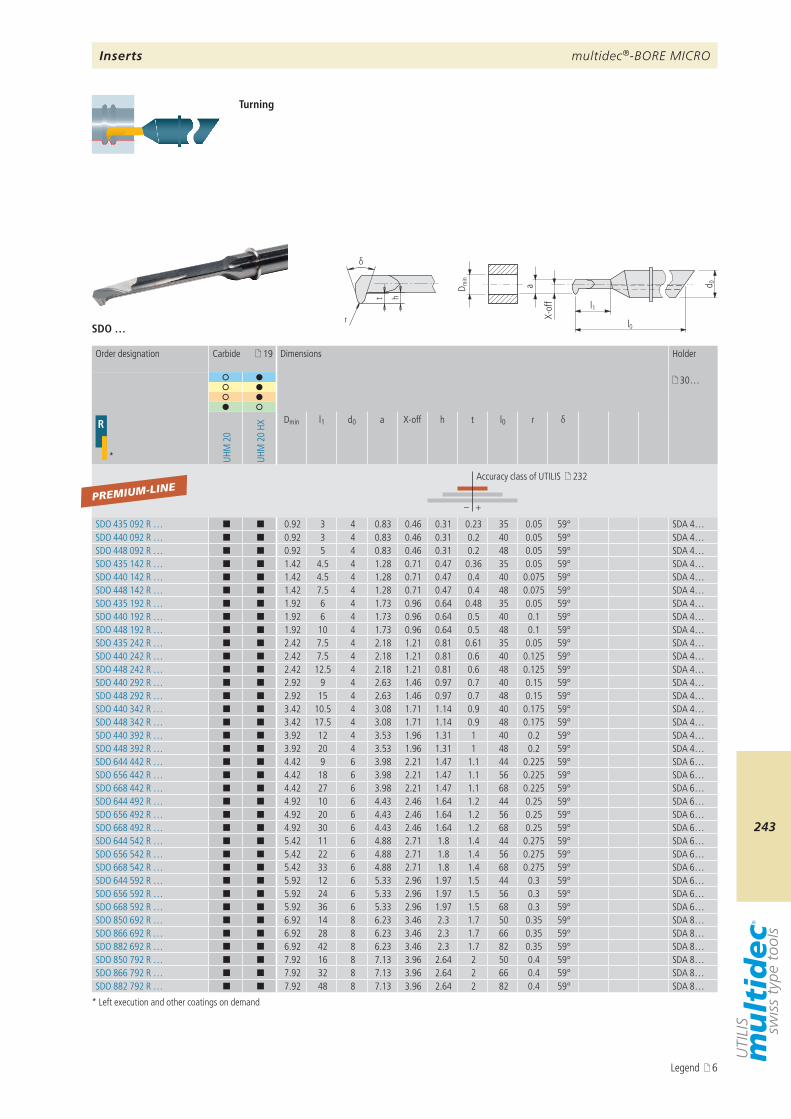
multidec®-BORE MICRO
243
a d 0
l1
l0
D min
X-of
f
r
t h
δ
SDO …
19
30…
R
* UHM
20
UHM
20
HX
Dmin l1 d0 a X-off h t l0 r δ
– +
SDO 435 092 R … ¢ ¢ 0.92 3 4 0.83 0.46 0.31 0.23 35 0.05 59° SDA 4…SDO 440 092 R … ¢ ¢ 0.92 3 4 0.83 0.46 0.31 0.2 40 0.05 59° SDA 4…SDO 448 092 R … ¢ ¢ 0.92 5 4 0.83 0.46 0.31 0.2 48 0.05 59° SDA 4…SDO 435 142 R … ¢ ¢ 1.42 4.5 4 1.28 0.71 0.47 0.36 35 0.05 59° SDA 4…SDO 440 142 R … ¢ ¢ 1.42 4.5 4 1.28 0.71 0.47 0.4 40 0.075 59° SDA 4…SDO 448 142 R … ¢ ¢ 1.42 7.5 4 1.28 0.71 0.47 0.4 48 0.075 59° SDA 4…SDO 435 192 R … ¢ ¢ 1.92 6 4 1.73 0.96 0.64 0.48 35 0.05 59° SDA 4…SDO 440 192 R … ¢ ¢ 1.92 6 4 1.73 0.96 0.64 0.5 40 0.1 59° SDA 4…SDO 448 192 R … ¢ ¢ 1.92 10 4 1.73 0.96 0.64 0.5 48 0.1 59° SDA 4…SDO 435 242 R … ¢ ¢ 2.42 7.5 4 2.18 1.21 0.81 0.61 35 0.05 59° SDA 4…SDO 440 242 R … ¢ ¢ 2.42 7.5 4 2.18 1.21 0.81 0.6 40 0.125 59° SDA 4…SDO 448 242 R … ¢ ¢ 2.42 12.5 4 2.18 1.21 0.81 0.6 48 0.125 59° SDA 4…SDO 440 292 R … ¢ ¢ 2.92 9 4 2.63 1.46 0.97 0.7 40 0.15 59° SDA 4…SDO 448 292 R … ¢ ¢ 2.92 15 4 2.63 1.46 0.97 0.7 48 0.15 59° SDA 4…SDO 440 342 R … ¢ ¢ 3.42 10.5 4 3.08 1.71 1.14 0.9 40 0.175 59° SDA 4…SDO 448 342 R … ¢ ¢ 3.42 17.5 4 3.08 1.71 1.14 0.9 48 0.175 59° SDA 4…SDO 440 392 R … ¢ ¢ 3.92 12 4 3.53 1.96 1.31 1 40 0.2 59° SDA 4…SDO 448 392 R … ¢ ¢ 3.92 20 4 3.53 1.96 1.31 1 48 0.2 59° SDA 4…SDO 644 442 R … ¢ ¢ 4.42 9 6 3.98 2.21 1.47 1.1 44 0.225 59° SDA 6…SDO 656 442 R … ¢ ¢ 4.42 18 6 3.98 2.21 1.47 1.1 56 0.225 59° SDA 6…SDO 668 442 R … ¢ ¢ 4.42 27 6 3.98 2.21 1.47 1.1 68 0.225 59° SDA 6…SDO 644 492 R … ¢ ¢ 4.92 10 6 4.43 2.46 1.64 1.2 44 0.25 59° SDA 6…SDO 656 492 R … ¢ ¢ 4.92 20 6 4.43 2.46 1.64 1.2 56 0.25 59° SDA 6…SDO 668 492 R … ¢ ¢ 4.92 30 6 4.43 2.46 1.64 1.2 68 0.25 59° SDA 6…SDO 644 542 R … ¢ ¢ 5.42 11 6 4.88 2.71 1.8 1.4 44 0.275 59° SDA 6…SDO 656 542 R … ¢ ¢ 5.42 22 6 4.88 2.71 1.8 1.4 56 0.275 59° SDA 6…SDO 668 542 R … ¢ ¢ 5.42 33 6 4.88 2.71 1.8 1.4 68 0.275 59° SDA 6…SDO 644 592 R … ¢ ¢ 5.92 12 6 5.33 2.96 1.97 1.5 44 0.3 59° SDA 6…SDO 656 592 R … ¢ ¢ 5.92 24 6 5.33 2.96 1.97 1.5 56 0.3 59° SDA 6…SDO 668 592 R … ¢ ¢ 5.92 36 6 5.33 2.96 1.97 1.5 68 0.3 59° SDA 6…SDO 850 692 R … ¢ ¢ 6.92 14 8 6.23 3.46 2.3 1.7 50 0.35 59° SDA 8…SDO 866 692 R … ¢ ¢ 6.92 28 8 6.23 3.46 2.3 1.7 66 0.35 59° SDA 8…SDO 882 692 R … ¢ ¢ 6.92 42 8 6.23 3.46 2.3 1.7 82 0.35 59° SDA 8…SDO 850 792 R … ¢ ¢ 7.92 16 8 7.13 3.96 2.64 2 50 0.4 59° SDA 8…SDO 866 792 R … ¢ ¢ 7.92 32 8 7.13 3.96 2.64 2 66 0.4 59° SDA 8…SDO 882 792 R … ¢ ¢ 7.92 48 8 7.13 3.96 2.64 2 82 0.4 59° SDA 8…
PREMIUM-LINE
Turning
* Left execution and other coatings on demand
Order designation Carbide Dimensions Holder
Accuracy class of UTILIS 232
Inserts
Legend 6

multidec®-BORE MICRO
244
a d 0
l1
l0
D min
X-of
f
r
t h
α
β
SDQ …
19
30…
R
* UHM
20
UHM
20
HX
Dmin l1 d0 a X-off h t l0 r α β
– +
SDQ 435 092 R … ¢ ¢ 0.92 1.5 4 0.83 0.46 0.31 0.23 35 0.05 0.5° 30.5° SDA 4…SDQ 440 092 R … ¢ ¢ 0.92 3 4 0.83 0.46 0.31 0.2 40 0.05 0.5° 30.5° SDA 4…SDQ 448 092 R … ¢ ¢ 0.92 5 4 0.83 0.46 0.31 0.2 48 0.05 0.5° 30.5° SDA 4…SDQ 435 142 R … ¢ ¢ 1.42 4.5 4 1.28 0.71 0.47 0.36 35 0.075 0.5° 30.5° SDA 4…SDQ 440 142 R … ¢ ¢ 1.42 4.5 4 1.28 0.71 0.47 0.4 40 0.075 0.5° 30.5° SDA 4…SDQ 448 142 R … ¢ ¢ 1.42 7.5 4 1.28 0.71 0.47 0.4 48 0.075 0.5° 30.5° SDA 4…SDQ 435 192 R … ¢ ¢ 1.92 6 4 1.73 0.96 0.64 0.48 35 0.1 0.5° 30.5° SDA 4…SDQ 440 192 R … ¢ ¢ 1.92 6 4 1.73 0.96 0.64 0.5 40 0.1 0.5° 30.5° SDA 4…SDQ 448 192 R … ¢ ¢ 1.92 10 4 1.73 0.96 0.64 0.5 48 0.1 0.5° 30.5° SDA 4…SDQ 435 242 R … ¢ ¢ 2.42 7.5 4 2.18 1.21 0.81 0.61 35 0.125 0.5° 30.5° SDA 4…SDQ 440 242 R … ¢ ¢ 2.42 7.5 4 2.18 1.21 0.81 0.6 40 0.125 0.5° 30.5° SDA 4…SDQ 448 242 R … ¢ ¢ 2.42 12.5 4 2.18 1.21 0.81 0.6 48 0.125 0.5° 30.5° SDA 4…SDQ 440 292 R … ¢ ¢ 2.92 9 4 2.63 1.46 0.97 0.7 40 0.15 0.5° 30.5° SDA 4…SDQ 448 292 R … ¢ ¢ 2.92 15 4 2.63 1.46 0.97 0.7 48 0.15 0.5° 30.5° SDA 4…SDQ 440 342 R … ¢ ¢ 3.42 10.5 4 3.08 1.71 1.14 0.9 40 0.175 0.5° 30.5° SDA 4…SDQ 448 342 R … ¢ ¢ 3.42 17.5 4 3.08 1.71 1.14 0.9 48 0.175 0.5° 30.5° SDA 4…SDQ 440 392 R … ¢ ¢ 3.92 12 4 3.53 1.96 1.31 1 40 0.2 0.5° 30.5° SDA 4…SDQ 448 392 R … ¢ ¢ 3.92 20 4 3.53 1.96 1.31 1 48 0.2 0.5° 30.5° SDA 4…SDQ 644 442 R … ¢ ¢ 4.42 9 6 3.98 2.21 1.47 1.1 44 0.225 0.5° 30.5° SDA 6…SDQ 656 442 R … ¢ ¢ 4.42 18 6 3.98 2.21 1.47 1.1 56 0.225 0.5° 30.5° SDA 6…SDQ 668 442 R … ¢ ¢ 4.42 27 6 3.98 2.21 1.47 1.1 68 0.225 0.5° 30.5° SDA 6…SDQ 644 492 R … ¢ ¢ 4.92 10 6 4.43 2.46 1.64 1.2 44 0.25 0.5° 30.5° SDA 6…SDQ 656 492 R … ¢ ¢ 4.92 20 6 4.43 2.46 1.64 1.2 56 0.25 0.5° 30.5° SDA 6…SDQ 668 492 R … ¢ ¢ 4.92 30 6 4.43 2.46 1.64 1.2 68 0.25 0.5° 30.5° SDA 6…SDQ 644 542 R … ¢ ¢ 5.42 11 6 4.88 2.71 1.8 1.4 44 0.275 0.5° 30.5° SDA 6…SDQ 656 542 R … ¢ ¢ 5.42 22 6 4.88 2.71 1.8 1.4 56 0.275 0.5° 30.5° SDA 6…SDQ 668 542 R … ¢ ¢ 5.42 33 6 4.88 2.71 1.8 1.4 68 0.275 0.5° 30.5° SDA 6…SDQ 644 592 R … ¢ ¢ 5.92 12 6 5.33 2.96 1.97 1.5 44 0.3 0.5° 30.5° SDA 6…SDQ 656 592 R … ¢ ¢ 5.92 24 6 5.33 2.96 1.97 1.5 56 0.3 0.5° 30.5° SDA 6…SDQ 668 592 R … ¢ ¢ 5.92 36 6 5.33 2.96 1.97 1.5 68 0.3 0.5° 30.5° SDA 6…SDQ 850 692 R … ¢ ¢ 6.92 14 8 6.23 3.46 2.3 1.7 50 0.35 0.5° 30.5° SDA 8…SDQ 866 692 R … ¢ ¢ 6.92 28 8 6.23 3.46 2.3 1.7 66 0.35 0.5° 30.5° SDA 8…SDQ 882 692 R … ¢ ¢ 6.92 42 8 6.23 3.46 2.3 1.7 82 0.35 0.5° 30.5° SDA 8…SDQ 850 792 R … ¢ ¢ 7.92 16 8 7.13 3.96 2.64 2 50 0.4 0.5° 30.5° SDA 8…SDQ 866 792 R … ¢ ¢ 7.92 32 8 7.13 3.96 2.64 2 66 0.4 0.5° 30.5° SDA 8…SDQ 882 792 R … ¢ ¢ 7.92 48 8 7.13 3.96 2.64 2 82 0.4 0.5° 30.5° SDA 8…
PREMIUM-LINE
Turning
* Left execution and other coatings on demand
Order designation Carbide Dimensions Holder
Accuracy class of UTILIS 232
Inserts
Legend 6
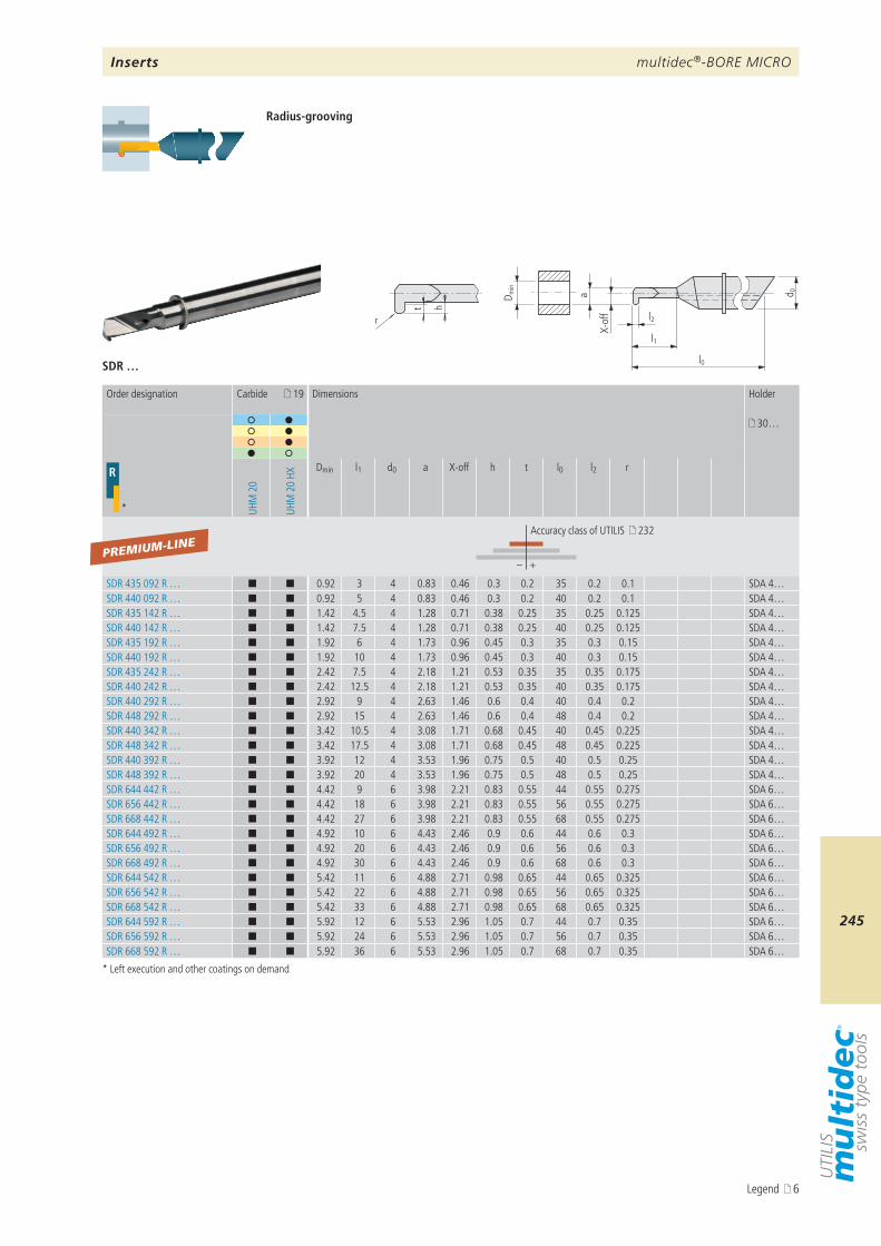
multidec®-BORE MICRO
245
a d 0
l1
l0
l2
D min
X-of
f
r
t h
SDR …
19
30…
R
* UHM
20
UHM
20
HX
Dmin l1 d0 a X-off h t l0 l2 r
– +
SDR 435 092 R … ¢ ¢ 0.92 3 4 0.83 0.46 0.3 0.2 35 0.2 0.1 SDA 4…SDR 440 092 R … ¢ ¢ 0.92 5 4 0.83 0.46 0.3 0.2 40 0.2 0.1 SDA 4…SDR 435 142 R … ¢ ¢ 1.42 4.5 4 1.28 0.71 0.38 0.25 35 0.25 0.125 SDA 4…SDR 440 142 R … ¢ ¢ 1.42 7.5 4 1.28 0.71 0.38 0.25 40 0.25 0.125 SDA 4…SDR 435 192 R … ¢ ¢ 1.92 6 4 1.73 0.96 0.45 0.3 35 0.3 0.15 SDA 4…SDR 440 192 R … ¢ ¢ 1.92 10 4 1.73 0.96 0.45 0.3 40 0.3 0.15 SDA 4…SDR 435 242 R … ¢ ¢ 2.42 7.5 4 2.18 1.21 0.53 0.35 35 0.35 0.175 SDA 4…SDR 440 242 R … ¢ ¢ 2.42 12.5 4 2.18 1.21 0.53 0.35 40 0.35 0.175 SDA 4…SDR 440 292 R … ¢ ¢ 2.92 9 4 2.63 1.46 0.6 0.4 40 0.4 0.2 SDA 4…SDR 448 292 R … ¢ ¢ 2.92 15 4 2.63 1.46 0.6 0.4 48 0.4 0.2 SDA 4…SDR 440 342 R … ¢ ¢ 3.42 10.5 4 3.08 1.71 0.68 0.45 40 0.45 0.225 SDA 4…SDR 448 342 R … ¢ ¢ 3.42 17.5 4 3.08 1.71 0.68 0.45 48 0.45 0.225 SDA 4…SDR 440 392 R … ¢ ¢ 3.92 12 4 3.53 1.96 0.75 0.5 40 0.5 0.25 SDA 4…SDR 448 392 R … ¢ ¢ 3.92 20 4 3.53 1.96 0.75 0.5 48 0.5 0.25 SDA 4…SDR 644 442 R … ¢ ¢ 4.42 9 6 3.98 2.21 0.83 0.55 44 0.55 0.275 SDA 6…SDR 656 442 R … ¢ ¢ 4.42 18 6 3.98 2.21 0.83 0.55 56 0.55 0.275 SDA 6…SDR 668 442 R … ¢ ¢ 4.42 27 6 3.98 2.21 0.83 0.55 68 0.55 0.275 SDA 6…SDR 644 492 R … ¢ ¢ 4.92 10 6 4.43 2.46 0.9 0.6 44 0.6 0.3 SDA 6…SDR 656 492 R … ¢ ¢ 4.92 20 6 4.43 2.46 0.9 0.6 56 0.6 0.3 SDA 6…SDR 668 492 R … ¢ ¢ 4.92 30 6 4.43 2.46 0.9 0.6 68 0.6 0.3 SDA 6…SDR 644 542 R … ¢ ¢ 5.42 11 6 4.88 2.71 0.98 0.65 44 0.65 0.325 SDA 6…SDR 656 542 R … ¢ ¢ 5.42 22 6 4.88 2.71 0.98 0.65 56 0.65 0.325 SDA 6…SDR 668 542 R … ¢ ¢ 5.42 33 6 4.88 2.71 0.98 0.65 68 0.65 0.325 SDA 6…SDR 644 592 R … ¢ ¢ 5.92 12 6 5.53 2.96 1.05 0.7 44 0.7 0.35 SDA 6…SDR 656 592 R … ¢ ¢ 5.92 24 6 5.53 2.96 1.05 0.7 56 0.7 0.35 SDA 6…SDR 668 592 R … ¢ ¢ 5.92 36 6 5.53 2.96 1.05 0.7 68 0.7 0.35 SDA 6…
PREMIUM-LINE
Radius-grooving
* Left execution and other coatings on demand
Order designation Carbide Dimensions Holder
Accuracy class of UTILIS 232
Inserts
Legend 6
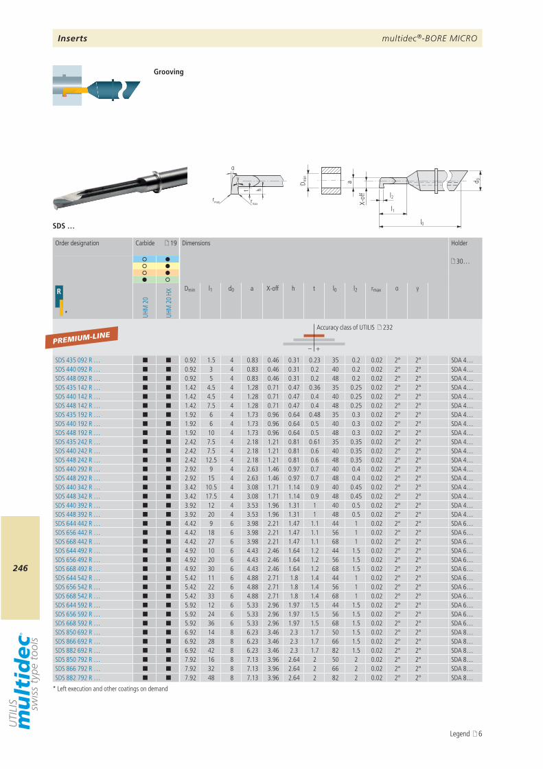
multidec®-BORE MICRO
246
a d 0
l1
l0
l2
D min
X-of
f
rmax rmax
t h
α
γ
SDS …
19
30…
R
* UHM
20
UHM
20
HX
Dmin l1 d0 a X-off h t l0 l2 rmax α γ
– +
SDS 435 092 R … ¢ ¢ 0.92 1.5 4 0.83 0.46 0.31 0.23 35 0.2 0.02 2° 2° SDA 4…SDS 440 092 R … ¢ ¢ 0.92 3 4 0.83 0.46 0.31 0.2 40 0.2 0.02 2° 2° SDA 4…SDS 448 092 R … ¢ ¢ 0.92 5 4 0.83 0.46 0.31 0.2 48 0.2 0.02 2° 2° SDA 4…SDS 435 142 R … ¢ ¢ 1.42 4.5 4 1.28 0.71 0.47 0.36 35 0.25 0.02 2° 2° SDA 4…SDS 440 142 R … ¢ ¢ 1.42 4.5 4 1.28 0.71 0.47 0.4 40 0.25 0.02 2° 2° SDA 4…SDS 448 142 R … ¢ ¢ 1.42 7.5 4 1.28 0.71 0.47 0.4 48 0.25 0.02 2° 2° SDA 4…SDS 435 192 R … ¢ ¢ 1.92 6 4 1.73 0.96 0.64 0.48 35 0.3 0.02 2° 2° SDA 4…SDS 440 192 R … ¢ ¢ 1.92 6 4 1.73 0.96 0.64 0.5 40 0.3 0.02 2° 2° SDA 4…SDS 448 192 R … ¢ ¢ 1.92 10 4 1.73 0.96 0.64 0.5 48 0.3 0.02 2° 2° SDA 4…SDS 435 242 R … ¢ ¢ 2.42 7.5 4 2.18 1.21 0.81 0.61 35 0.35 0.02 2° 2° SDA 4…SDS 440 242 R … ¢ ¢ 2.42 7.5 4 2.18 1.21 0.81 0.6 40 0.35 0.02 2° 2° SDA 4…SDS 448 242 R … ¢ ¢ 2.42 12.5 4 2.18 1.21 0.81 0.6 48 0.35 0.02 2° 2° SDA 4…SDS 440 292 R … ¢ ¢ 2.92 9 4 2.63 1.46 0.97 0.7 40 0.4 0.02 2° 2° SDA 4…SDS 448 292 R … ¢ ¢ 2.92 15 4 2.63 1.46 0.97 0.7 48 0.4 0.02 2° 2° SDA 4…SDS 440 342 R … ¢ ¢ 3.42 10.5 4 3.08 1.71 1.14 0.9 40 0.45 0.02 2° 2° SDA 4…SDS 448 342 R … ¢ ¢ 3.42 17.5 4 3.08 1.71 1.14 0.9 48 0.45 0.02 2° 2° SDA 4…SDS 440 392 R … ¢ ¢ 3.92 12 4 3.53 1.96 1.31 1 40 0.5 0.02 2° 2° SDA 4…SDS 448 392 R … ¢ ¢ 3.92 20 4 3.53 1.96 1.31 1 48 0.5 0.02 2° 2° SDA 4…SDS 644 442 R … ¢ ¢ 4.42 9 6 3.98 2.21 1.47 1.1 44 1 0.02 2° 2° SDA 6…SDS 656 442 R … ¢ ¢ 4.42 18 6 3.98 2.21 1.47 1.1 56 1 0.02 2° 2° SDA 6…SDS 668 442 R … ¢ ¢ 4.42 27 6 3.98 2.21 1.47 1.1 68 1 0.02 2° 2° SDA 6…SDS 644 492 R … ¢ ¢ 4.92 10 6 4.43 2.46 1.64 1.2 44 1.5 0.02 2° 2° SDA 6…SDS 656 492 R … ¢ ¢ 4.92 20 6 4.43 2.46 1.64 1.2 56 1.5 0.02 2° 2° SDA 6…SDS 668 492 R … ¢ ¢ 4.92 30 6 4.43 2.46 1.64 1.2 68 1.5 0.02 2° 2° SDA 6…SDS 644 542 R … ¢ ¢ 5.42 11 6 4.88 2.71 1.8 1.4 44 1 0.02 2° 2° SDA 6…SDS 656 542 R … ¢ ¢ 5.42 22 6 4.88 2.71 1.8 1.4 56 1 0.02 2° 2° SDA 6…SDS 668 542 R … ¢ ¢ 5.42 33 6 4.88 2.71 1.8 1.4 68 1 0.02 2° 2° SDA 6…SDS 644 592 R … ¢ ¢ 5.92 12 6 5.33 2.96 1.97 1.5 44 1.5 0.02 2° 2° SDA 6…SDS 656 592 R … ¢ ¢ 5.92 24 6 5.33 2.96 1.97 1.5 56 1.5 0.02 2° 2° SDA 6…SDS 668 592 R … ¢ ¢ 5.92 36 6 5.33 2.96 1.97 1.5 68 1.5 0.02 2° 2° SDA 6…SDS 850 692 R … ¢ ¢ 6.92 14 8 6.23 3.46 2.3 1.7 50 1.5 0.02 2° 2° SDA 8…SDS 866 692 R … ¢ ¢ 6.92 28 8 6.23 3.46 2.3 1.7 66 1.5 0.02 2° 2° SDA 8…SDS 882 692 R … ¢ ¢ 6.92 42 8 6.23 3.46 2.3 1.7 82 1.5 0.02 2° 2° SDA 8…SDS 850 792 R … ¢ ¢ 7.92 16 8 7.13 3.96 2.64 2 50 2 0.02 2° 2° SDA 8…SDS 866 792 R … ¢ ¢ 7.92 32 8 7.13 3.96 2.64 2 66 2 0.02 2° 2° SDA 8…SDS 882 792 R … ¢ ¢ 7.92 48 8 7.13 3.96 2.64 2 82 2 0.02 2° 2° SDA 8…
PREMIUM-LINE
Grooving
* Left execution and other coatings on demand
Order designation Carbide Dimensions Holder
Accuracy class of UTILIS 232
Inserts
Legend 6
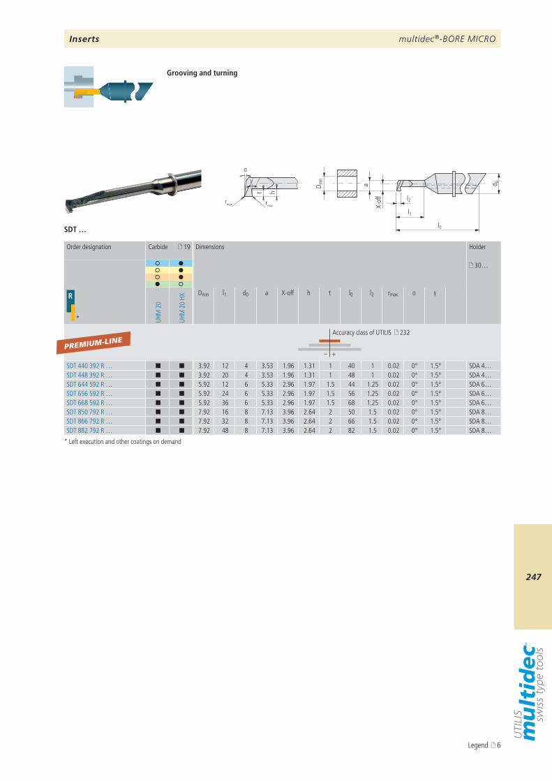
multidec®-BORE MICRO
247
D min
a d 0
l1
l0
l2
X-of
f
rmax rmax
t h
α
γ
SDT …
19
30…
R
* UHM
20
UHM
20
HX
Dmin l1 d0 a X-off h t l0 l2 rmax α γ
– +
SDT 440 392 R … ¢ ¢ 3.92 12 4 3.53 1.96 1.31 1 40 1 0.02 0° 1.5° SDA 4…SDT 448 392 R … ¢ ¢ 3.92 20 4 3.53 1.96 1.31 1 48 1 0.02 0° 1.5° SDA 4…SDT 644 592 R … ¢ ¢ 5.92 12 6 5.33 2.96 1.97 1.5 44 1.25 0.02 0° 1.5° SDA 6…SDT 656 592 R … ¢ ¢ 5.92 24 6 5.33 2.96 1.97 1.5 56 1.25 0.02 0° 1.5° SDA 6…SDT 668 592 R … ¢ ¢ 5.92 36 6 5.33 2.96 1.97 1.5 68 1.25 0.02 0° 1.5° SDA 6…SDT 850 792 R … ¢ ¢ 7.92 16 8 7.13 3.96 2.64 2 50 1.5 0.02 0° 1.5° SDA 8…SDT 866 792 R … ¢ ¢ 7.92 32 8 7.13 3.96 2.64 2 66 1.5 0.02 0° 1.5° SDA 8…SDT 882 792 R … ¢ ¢ 7.92 48 8 7.13 3.96 2.64 2 82 1.5 0.02 0° 1.5° SDA 8…
PREMIUM-LINE
Grooving and turning
* Left execution and other coatings on demand
Order designation Carbide Dimensions Holder
Accuracy class of UTILIS 232
Inserts
Legend 6
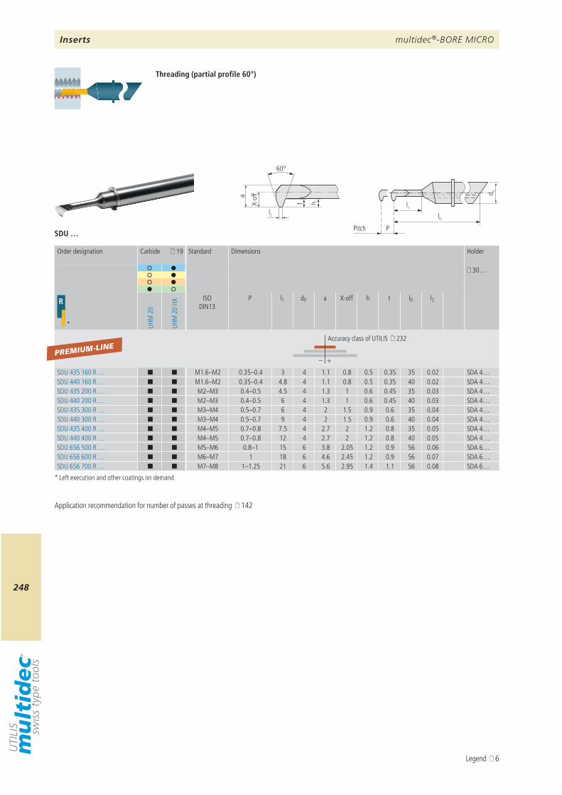
multidec®-BORE MICRO
248
d 0
l0
l1
P
l2
htX-of
f
60°
aSDU …
19
30…
R
* UHM
20
UHM
20
HX
ISO DIN13
P l1 d0 a X-off h t l0 l2
– +
SDU 435 160 R … ¢ ¢ M1.6–M2 0.35–0.4 3 4 1.1 0.8 0.5 0.35 35 0.02 SDA 4…SDU 440 160 R … ¢ ¢ M1.6–M2 0.35–0.4 4.8 4 1.1 0.8 0.5 0.35 40 0.02 SDA 4…SDU 435 200 R … ¢ ¢ M2–M3 0.4–0.5 4.5 4 1.3 1 0.6 0.45 35 0.03 SDA 4…SDU 440 200 R … ¢ ¢ M2–M3 0.4–0.5 6 4 1.3 1 0.6 0.45 40 0.03 SDA 4…SDU 435 300 R … ¢ ¢ M3–M4 0.5–0.7 6 4 2 1.5 0.9 0.6 35 0.04 SDA 4…SDU 440 300 R … ¢ ¢ M3–M4 0.5–0.7 9 4 2 1.5 0.9 0.6 40 0.04 SDA 4…SDU 435 400 R … ¢ ¢ M4–M5 0.7–0.8 7.5 4 2.7 2 1.2 0.8 35 0.05 SDA 4…SDU 440 400 R … ¢ ¢ M4–M5 0.7–0.8 12 4 2.7 2 1.2 0.8 40 0.05 SDA 4…SDU 656 500 R … ¢ ¢ M5–M6 0.8–1 15 6 3.8 2.05 1.2 0.9 56 0.06 SDA 6…SDU 656 600 R … ¢ ¢ M6–M7 1 18 6 4.6 2.45 1.2 0.9 56 0.07 SDA 6…SDU 656 700 R … ¢ ¢ M7–M8 1–1.25 21 6 5.6 2.95 1.4 1.1 56 0.08 SDA 6…
PREMIUM-LINE
Pitch
Threading (partial profile 60°)
* Left execution and other coatings on demand
Order designation Carbide Standard Dimensions Holder
Accuracy class of UTILIS 232
Inserts
Application recommendation for number of passes at threading 142
Legend 6
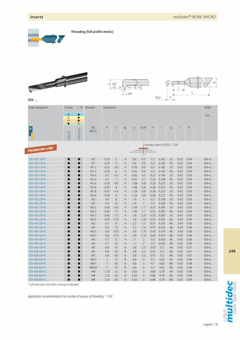
multidec®-BORE MICRO
249
d 0
l0
l1
P
r
h
60°
Vr VrX-of
f
t
a
SDV …
19
30…
R
* UHM
20
UHM
20
HX
ISO DIN13
P l1 d0 a X-off h t l0 r Vr
– +
SDV 435 100 R … ¢ ¢ M1 0.25 3 4 0.6 0.5 0.2 0.162 35 0.02 0.04 SDA 4…SDV 440 100 R … ¢ ¢ M1 0.25 5 4 0.6 0.5 0.2 0.162 40 0.02 0.04 SDA 4…SDV 435 120 R … ¢ ¢ M1.2 0.25 3.6 4 0.76 0.6 0.2 0.162 35 0.02 0.04 SDA 4…SDV 440 120 R … ¢ ¢ M1.2 0.25 6 4 0.76 0.6 0.2 0.162 40 0.02 0.04 SDA 4…SDV 435 140 R … ¢ ¢ M1.4 0.3 4.2 4 0.92 0.7 0.23 0.194 35 0.02 0.05 SDA 4…SDV 440 140 R … ¢ ¢ M1.4 0.3 7 4 0.92 0.7 0.23 0.194 40 0.02 0.05 SDA 4…SDV 435 160 R … ¢ ¢ M1.6 0.35 4.8 4 1.08 0.8 0.26 0.227 35 0.03 0.05 SDA 4…SDV 440 160 R … ¢ ¢ M1.6 0.35 8 4 1.08 0.8 0.26 0.227 40 0.03 0.05 SDA 4…SDV 435 180 R … ¢ ¢ M1.8 0.35 5.4 4 1.24 0.9 0.26 0.227 35 0.03 0.05 SDA 4…SDV 440 180 R … ¢ ¢ M1.8 0.35 9 4 1.24 0.9 0.26 0.227 40 0.03 0.05 SDA 4…SDV 435 200 R … ¢ ¢ M2 0.4 6 4 1.4 1 0.3 0.258 35 0.03 0.05 SDA 4…SDV 440 200 R … ¢ ¢ M2 0.4 10 4 1.4 1 0.3 0.258 40 0.03 0.05 SDA 4…SDV 435 220 R … ¢ ¢ M2.2 0.45 6.6 4 1.56 1.1 0.33 0.287 35 0.03 0.05 SDA 4…SDV 440 220 R … ¢ ¢ M2.2 0.45 11 4 1.56 1.1 0.33 0.287 40 0.03 0.05 SDA 4…SDV 435 250 R … ¢ ¢ M2.5 0.45 7.5 4 1.8 1.25 0.33 0.287 35 0.03 0.05 SDA 4…SDV 440 250 R … ¢ ¢ M2.5 0.45 12.5 4 1.8 1.25 0.33 0.287 40 0.03 0.05 SDA 4…SDV 440 300 R … ¢ ¢ M3 0.5 9 4 2.2 1.5 0.37 0.316 40 0.04 0.06 SDA 4…SDV 448 300 R … ¢ ¢ M3 0.5 15 4 2.2 1.5 0.37 0.316 48 0.04 0.06 SDA 4…SDV 440 350 R … ¢ ¢ M3.5 0.6 10.5 4 2.6 1.75 0.43 0.374 40 0.04 0.06 SDA 4…SDV 448 350 R … ¢ ¢ M3.5 0.6 17.5 4 2.6 1.75 0.43 0.374 48 0.04 0.06 SDA 4…SDV 440 400 R … ¢ ¢ M4 0.7 12 4 3 2 0.5 0.432 40 0.05 0.06 SDA 4…SDV 448 400 R … ¢ ¢ M4 0.7 20 4 3 2 0.5 0.432 48 0.05 0.06 SDA 4…SDV 644 500 R … ¢ ¢ M5 0.8 10 6 3.8 2.5 0.57 0.5 44 0.05 0.07 SDA 6…SDV 656 500 R … ¢ ¢ M5 0.8 20 6 3.8 2.5 0.57 0.5 56 0.05 0.07 SDA 6…SDV 668 500 R … ¢ ¢ M5 0.8 30 6 3.8 2.5 0.57 0.5 68 0.05 0.07 SDA 6…SDV 644 600 R … ¢ ¢ M6/7 1 12 6 4.6 3 0.7 0.62 44 0.05 0.08 SDA 6…SDV 668 600 R … ¢ ¢ M6/7 1 36 6 4.6 3 0.7 0.62 68 0.05 0.08 SDA 6…SDV 656 600 R … ¢ ¢ M6/M7 1 24 6 4.6 3 0.7 0.62 56 0.05 0.08 SDA 6…SDV 644 800 R … ¢ ¢ M8 1.25 12 6 5.62 3 0.86 0.78 44 0.05 0.09 SDA 6…SDV 656 800 R … ¢ ¢ M8 1.25 24 6 5.62 3 0.86 0.78 56 0.05 0.09 SDA 6…SDV 668 800 R … ¢ ¢ M8 1.25 36 6 5.62 3 0.86 0.78 68 0.05 0.09 SDA 6…
PREMIUM-LINE
Pitch
Threading (full profile metric)
* Left execution and other coatings on demand
Order designation Carbide Standard Dimensions Holder
Accuracy class of UTILIS 232
Inserts
Application recommendation for number of passes at threading 142
Legend 6
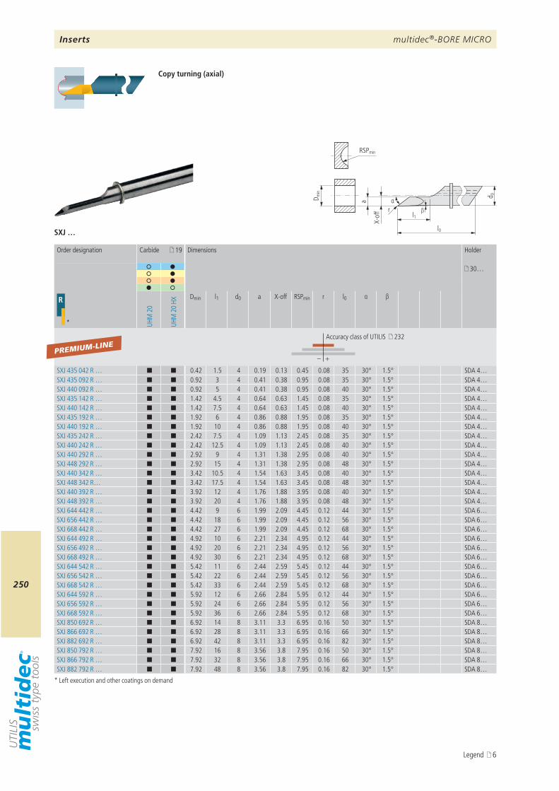
multidec®-BORE MICRO
250
β
D min
a
d 0
l0
l1
αr
RSPmin
X-of
f
SXJ …
19
30…
R
* UHM
20
UHM
20
HX
Dmin l1 d0 a X-off RSPmin r l0 α β
– +
SXJ 435 042 R … ¢ ¢ 0.42 1.5 4 0.19 0.13 0.45 0.08 35 30° 1.5° SDA 4…SXJ 435 092 R … ¢ ¢ 0.92 3 4 0.41 0.38 0.95 0.08 35 30° 1.5° SDA 4…SXJ 440 092 R … ¢ ¢ 0.92 5 4 0.41 0.38 0.95 0.08 40 30° 1.5° SDA 4…SXJ 435 142 R … ¢ ¢ 1.42 4.5 4 0.64 0.63 1.45 0.08 35 30° 1.5° SDA 4…SXJ 440 142 R … ¢ ¢ 1.42 7.5 4 0.64 0.63 1.45 0.08 40 30° 1.5° SDA 4…SXJ 435 192 R … ¢ ¢ 1.92 6 4 0.86 0.88 1.95 0.08 35 30° 1.5° SDA 4…SXJ 440 192 R … ¢ ¢ 1.92 10 4 0.86 0.88 1.95 0.08 40 30° 1.5° SDA 4…SXJ 435 242 R … ¢ ¢ 2.42 7.5 4 1.09 1.13 2.45 0.08 35 30° 1.5° SDA 4…SXJ 440 242 R … ¢ ¢ 2.42 12.5 4 1.09 1.13 2.45 0.08 40 30° 1.5° SDA 4…SXJ 440 292 R … ¢ ¢ 2.92 9 4 1.31 1.38 2.95 0.08 40 30° 1.5° SDA 4…SXJ 448 292 R … ¢ ¢ 2.92 15 4 1.31 1.38 2.95 0.08 48 30° 1.5° SDA 4…SXJ 440 342 R … ¢ ¢ 3.42 10.5 4 1.54 1.63 3.45 0.08 40 30° 1.5° SDA 4…SXJ 448 342 R… ¢ ¢ 3.42 17.5 4 1.54 1.63 3.45 0.08 48 30° 1.5° SDA 4…SXJ 440 392 R … ¢ ¢ 3.92 12 4 1.76 1.88 3.95 0.08 40 30° 1.5° SDA 4…SXJ 448 392 R … ¢ ¢ 3.92 20 4 1.76 1.88 3.95 0.08 48 30° 1.5° SDA 4…SXJ 644 442 R … ¢ ¢ 4.42 9 6 1.99 2.09 4.45 0.12 44 30° 1.5° SDA 6…SXJ 656 442 R … ¢ ¢ 4.42 18 6 1.99 2.09 4.45 0.12 56 30° 1.5° SDA 6…SXJ 668 442 R … ¢ ¢ 4.42 27 6 1.99 2.09 4.45 0.12 68 30° 1.5° SDA 6…SXJ 644 492 R … ¢ ¢ 4.92 10 6 2.21 2.34 4.95 0.12 44 30° 1.5° SDA 6…SXJ 656 492 R … ¢ ¢ 4.92 20 6 2.21 2.34 4.95 0.12 56 30° 1.5° SDA 6…SXJ 668 492 R … ¢ ¢ 4.92 30 6 2.21 2.34 4.95 0.12 68 30° 1.5° SDA 6…SXJ 644 542 R … ¢ ¢ 5.42 11 6 2.44 2.59 5.45 0.12 44 30° 1.5° SDA 6…SXJ 656 542 R … ¢ ¢ 5.42 22 6 2.44 2.59 5.45 0.12 56 30° 1.5° SDA 6…SXJ 668 542 R … ¢ ¢ 5.42 33 6 2.44 2.59 5.45 0.12 68 30° 1.5° SDA 6…SXJ 644 592 R … ¢ ¢ 5.92 12 6 2.66 2.84 5.95 0.12 44 30° 1.5° SDA 6…SXJ 656 592 R … ¢ ¢ 5.92 24 6 2.66 2.84 5.95 0.12 56 30° 1.5° SDA 6…SXJ 668 592 R … ¢ ¢ 5.92 36 6 2.66 2.84 5.95 0.12 68 30° 1.5° SDA 6…SXJ 850 692 R … ¢ ¢ 6.92 14 8 3.11 3.3 6.95 0.16 50 30° 1.5° SDA 8…SXJ 866 692 R … ¢ ¢ 6.92 28 8 3.11 3.3 6.95 0.16 66 30° 1.5° SDA 8…SXJ 882 692 R … ¢ ¢ 6.92 42 8 3.11 3.3 6.95 0.16 82 30° 1.5° SDA 8…SXJ 850 792 R … ¢ ¢ 7.92 16 8 3.56 3.8 7.95 0.16 50 30° 1.5° SDA 8…SXJ 866 792 R … ¢ ¢ 7.92 32 8 3.56 3.8 7.95 0.16 66 30° 1.5° SDA 8…SXJ 882 792 R … ¢ ¢ 7.92 48 8 3.56 3.8 7.95 0.16 82 30° 1.5° SDA 8…
PREMIUM-LINE
Copy turning (axial)
* Left execution and other coatings on demand
Order designation Carbide Dimensions Holder
Accuracy class of UTILIS 232
Inserts
Legend 6
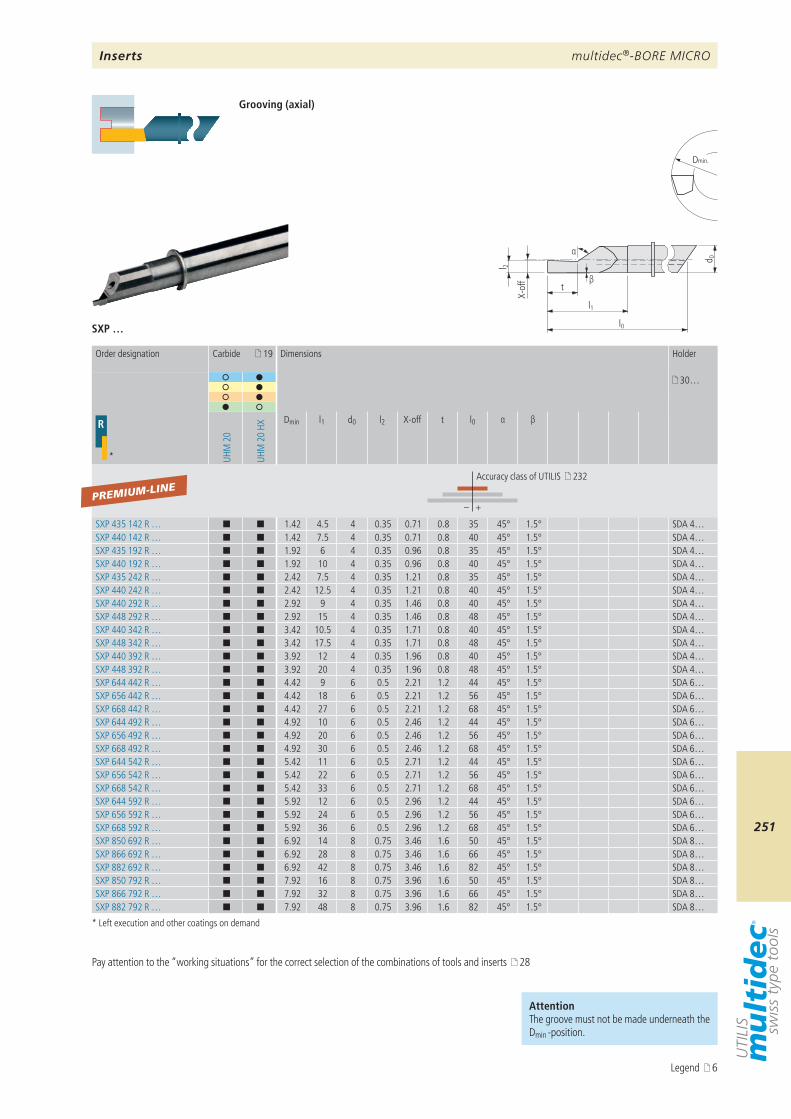
multidec®-BORE MICRO
251
β
α
l 2
d 0
l1
l0
t
Dmin.
X-of
f
SXP …
19
30…
R
* UHM
20
UHM
20
HX
Dmin l1 d0 l2 X-off t l0 α β
– +
SXP 435 142 R … ¢ ¢ 1.42 4.5 4 0.35 0.71 0.8 35 45° 1.5° SDA 4…SXP 440 142 R … ¢ ¢ 1.42 7.5 4 0.35 0.71 0.8 40 45° 1.5° SDA 4…SXP 435 192 R … ¢ ¢ 1.92 6 4 0.35 0.96 0.8 35 45° 1.5° SDA 4…SXP 440 192 R … ¢ ¢ 1.92 10 4 0.35 0.96 0.8 40 45° 1.5° SDA 4…SXP 435 242 R … ¢ ¢ 2.42 7.5 4 0.35 1.21 0.8 35 45° 1.5° SDA 4…SXP 440 242 R … ¢ ¢ 2.42 12.5 4 0.35 1.21 0.8 40 45° 1.5° SDA 4…SXP 440 292 R … ¢ ¢ 2.92 9 4 0.35 1.46 0.8 40 45° 1.5° SDA 4…SXP 448 292 R … ¢ ¢ 2.92 15 4 0.35 1.46 0.8 48 45° 1.5° SDA 4…SXP 440 342 R … ¢ ¢ 3.42 10.5 4 0.35 1.71 0.8 40 45° 1.5° SDA 4…SXP 448 342 R … ¢ ¢ 3.42 17.5 4 0.35 1.71 0.8 48 45° 1.5° SDA 4…SXP 440 392 R … ¢ ¢ 3.92 12 4 0.35 1.96 0.8 40 45° 1.5° SDA 4…SXP 448 392 R … ¢ ¢ 3.92 20 4 0.35 1.96 0.8 48 45° 1.5° SDA 4…SXP 644 442 R … ¢ ¢ 4.42 9 6 0.5 2.21 1.2 44 45° 1.5° SDA 6…SXP 656 442 R … ¢ ¢ 4.42 18 6 0.5 2.21 1.2 56 45° 1.5° SDA 6…SXP 668 442 R … ¢ ¢ 4.42 27 6 0.5 2.21 1.2 68 45° 1.5° SDA 6…SXP 644 492 R … ¢ ¢ 4.92 10 6 0.5 2.46 1.2 44 45° 1.5° SDA 6…SXP 656 492 R … ¢ ¢ 4.92 20 6 0.5 2.46 1.2 56 45° 1.5° SDA 6…SXP 668 492 R … ¢ ¢ 4.92 30 6 0.5 2.46 1.2 68 45° 1.5° SDA 6…SXP 644 542 R … ¢ ¢ 5.42 11 6 0.5 2.71 1.2 44 45° 1.5° SDA 6…SXP 656 542 R … ¢ ¢ 5.42 22 6 0.5 2.71 1.2 56 45° 1.5° SDA 6…SXP 668 542 R … ¢ ¢ 5.42 33 6 0.5 2.71 1.2 68 45° 1.5° SDA 6…SXP 644 592 R … ¢ ¢ 5.92 12 6 0.5 2.96 1.2 44 45° 1.5° SDA 6…SXP 656 592 R … ¢ ¢ 5.92 24 6 0.5 2.96 1.2 56 45° 1.5° SDA 6…SXP 668 592 R … ¢ ¢ 5.92 36 6 0.5 2.96 1.2 68 45° 1.5° SDA 6…SXP 850 692 R … ¢ ¢ 6.92 14 8 0.75 3.46 1.6 50 45° 1.5° SDA 8…SXP 866 692 R … ¢ ¢ 6.92 28 8 0.75 3.46 1.6 66 45° 1.5° SDA 8…SXP 882 692 R … ¢ ¢ 6.92 42 8 0.75 3.46 1.6 82 45° 1.5° SDA 8…SXP 850 792 R … ¢ ¢ 7.92 16 8 0.75 3.96 1.6 50 45° 1.5° SDA 8…SXP 866 792 R … ¢ ¢ 7.92 32 8 0.75 3.96 1.6 66 45° 1.5° SDA 8…SXP 882 792 R … ¢ ¢ 7.92 48 8 0.75 3.96 1.6 82 45° 1.5° SDA 8…
PREMIUM-LINE
Grooving (axial)
* Left execution and other coatings on demand
Order designation Carbide Dimensions Holder
Accuracy class of UTILIS 232
AttentionThe groove must not be made underneath the Dmin -position.
Pay attention to the “working situations” for the correct selection of the combinations of tools and inserts 28
Inserts
Legend 6
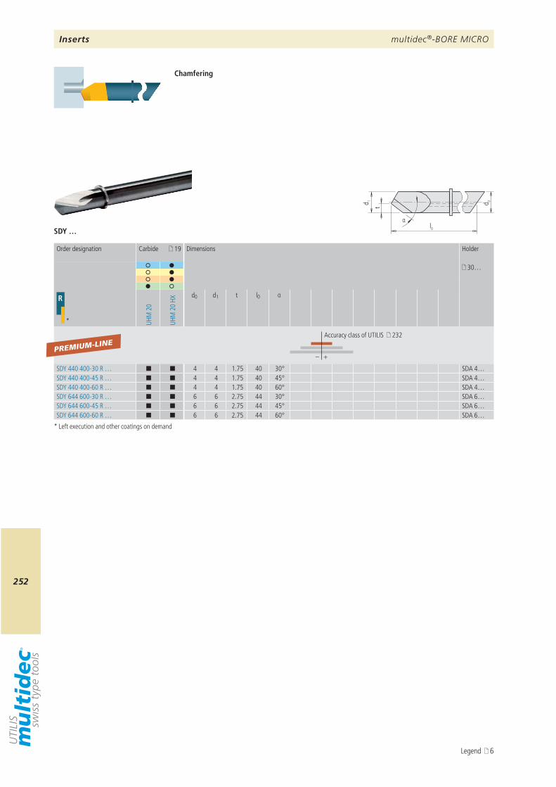
multidec®-BORE MICRO
252
d 0
l0
t
α
d 1
SDY …
19
30…
R
* UHM
20
UHM
20
HX
d0 d1 t l0 α
– +
SDY 440 400-30 R … ¢ ¢ 4 4 1.75 40 30° SDA 4…SDY 440 400-45 R … ¢ ¢ 4 4 1.75 40 45° SDA 4…SDY 440 400-60 R … ¢ ¢ 4 4 1.75 40 60° SDA 4…SDY 644 600-30 R … ¢ ¢ 6 6 2.75 44 30° SDA 6…SDY 644 600-45 R … ¢ ¢ 6 6 2.75 44 45° SDA 6…SDY 644 600-60 R … ¢ ¢ 6 6 2.75 44 60° SDA 6…
PREMIUM-LINE
Chamfering
* Left execution and other coatings on demand
Order designation Carbide Dimensions Holder
Accuracy class of UTILIS 232
Inserts
Legend 6
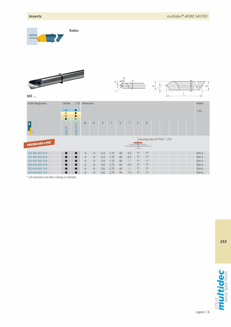
multidec®-BORE MICRO
253
r
b αβ
d 0
l0
d 1
t
SDZ …
19
30…
R
* UHM
20
UHM
20
HX
d0 d1 b t l0 r α β
– +
SDZ 440 400-03 R … ¢ ¢ 4 4 0.4 1.75 40 0.3 7° 7° SDA 4…SDZ 440 400-05 R … ¢ ¢ 4 4 0.4 1.75 40 0.5 7° 7° SDA 4…SDZ 440 400-10 R … ¢ ¢ 4 4 0.4 1.75 40 1 7° 7° SDA 4…SDZ 644 600-05 R … ¢ ¢ 6 6 0.6 2.75 44 0.5 7° 7° SDA 6…SDZ 644 600-10 R … ¢ ¢ 6 6 0.6 2.75 44 1. 7° 7° SDA 6…SDZ 644 600-15 R … ¢ ¢ 6 6 0.6 2.75 44 1.5 7° 7° SDA 6…
PREMIUM-LINE
Radius
* Left execution and other coatings on demand
Order designation Carbide Dimensions Holder
Accuracy class of UTILIS 232
Inserts
Legend 6
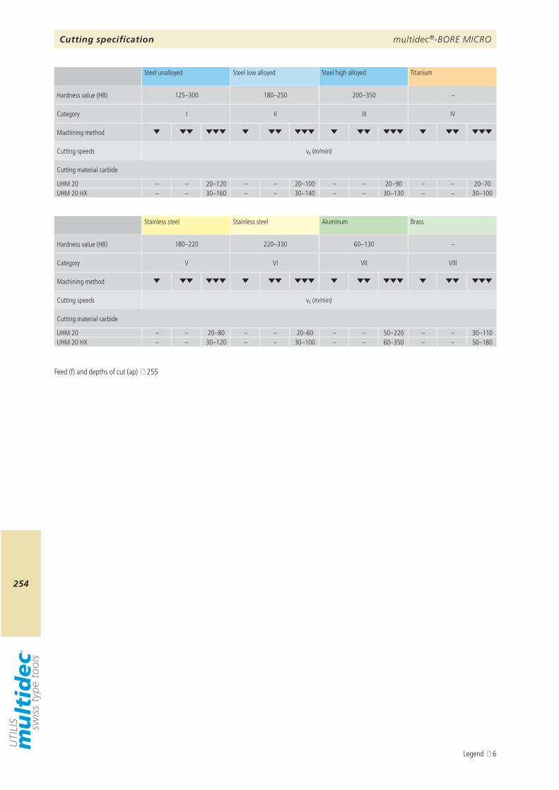
multidec®-BORE MICRO
254
125–300 180–250 200–350 –
I II III IV
vc (m/min)
UHM 20 – – 20–120 – – 20–100 – – 20–90 – – 20–70UHM 20 HX – – 30–160 – – 30–140 – – 30–130 – – 30–100
180–220 220–330 60–130 –
V VI VII VIII
vc (m/min)
UHM 20 – – 20–80 – – 20–60 – – 50–220 – – 30–110UHM 20 HX – – 30–120 – – 30–100 – – 60–350 – – 50–180
Cutting specification
Feed (f) and depths of cut (ap) 255
Steel unalloyed Steel low alloyed Steel high alloyed Titanium
Hardness value (HB)
Category
Machining method
Cutting speeds
Cutting material carbide
Stainless steel Stainless steel Aluminum Brass
Hardness value (HB)
Category
Machining method
Cutting speeds
Cutting material carbide
Legend 6
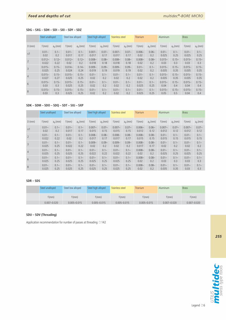
multidec®-BORE MICRO
255
D (mm) f (mm) ap (mm) f (mm) ap (mm) f (mm) ap (mm) f (mm) ap (mm) f (mm) ap (mm) f (mm) ap (mm) f (mm) ap (mm)
≤1 0.01–0.02
0.1–0.2
0.01–0.017
0.1–0.17
0.007–0.017
0.07–0.17
0.007–0.017
0.07–0.17
0.006–0.02
0.06–0.2
0.01–0.025
0.1–0.25
0.01–0.025
0.1–0.25
2 0.012–0.022
0.12–0.22
0.012–0.02
0.12–0.2
0.008–0.018
0.08–0.18
0.008–0.018
0.08–0.18
0.008–0.02
0.08–0.2
0.015–0.03
0.15–0.3
0.015–0.03
0.15–0.3
3 0.015–0.025
0.15–0.25
0.014–0.024
0.14–0.24
0.009–0.019
0.09–0.19
0.009–0.019
0.09–0.19
0.01–0.02
0.1–0.2
0.015–0.035
0.15–0.35
0.015–0.035
0.15–0.35
4 0.015–0.027
0.15–0.27
0.015–0.025
0.15–0.25
0.01–0.02
0.1–0.2
0.01–0.02
0.1–0.2
0.01–0.02
0.1–0.2
0.015–0.035
0.15–0.35
0.015–0.035
0.15–0.35
6 0.015–0.03
0.15–0.3
0.015–0.025
0.15–0.25
0.01–0.02
0.1–0.2
0.01–0.02
0.1–0.2
0.01–0.025
0.1–0.25
0.015–0.04
0.15–0.4
0.015–0.04
0.15–0.4
8 0.015–0.03
0.15–0.3
0.015–0.025
0.15–0.25
0.01–0.02
0.1–0.2
0.01–0.02
0.1–0.2
0.01–0.025
0.1–0.25
0.015–0.05
0.15–0.5
0.015–0.04
0.15–0.4
SDG – SXG – SDH – SDI – SXI – SDY – SDZ
D (mm) f (mm) ap (mm) f (mm) ap (mm) f (mm) ap (mm) f (mm) ap (mm) f (mm) ap (mm) f (mm) ap (mm) f (mm) ap (mm)
≤1 0.01–0.02
0.1–0.2
0.01–0.017
0.1–0.17
0.007–0.015
0.07–0.15
0.007–0.015
0.07–0.15
0.006–0.012
0.06–0.12
0.007–0.012
0.07–0.12
0.007–0.012
0.07–0.12
2 0.01–0.022
0.1–0.22
0.01–0.02
0.1–0.2
0.008–0.017
0.08–0.17
0.008–0.017
0.08–0.17
0.008–0.015
0.08–0.15
0.01–0.015
0.1–0.15
0.01–0.015
0.1–0.15
3 0.01–0.025
0.1–0.25
0.01–0.022
0.1–0.22
0.009–0.02
0.09–0.2
0.009–0.02
0.09–0.2
0.008–0.017
0.08–0.17
0.01–0.02
0.1–0.2
0.01–0.02
0.1–0.2
4 0.01–0.025
0.1–0.25
0.01–0.025
0.1–0.25
0.01–0.022
0.1–0.22
0.01–0.022
0.1–0.22
0.008–0.02
0.08–0.2
0.01–0.025
0.1–0.25
0.01–0.025
0.1–0.25
6 0.01–0.025
0.1–0.25
0.01–0.025
0.1–0.25
0.01–0.025
0.1–0.25
0.01–0.025
0.1–0.25
0.008–0.02
0.08–0.2
0.01–0.03
0.1–0.3
0.01–0.03
0.1–0.3
8 0.01–0.025
0.1–0.25
0.01–0.025
0.1–0.25
0.01–0.025
0.1–0.25
0.01–0.025
0.1–0.25
0.008–0.02
0.08–0.2
0.01–0.035
0.1–0.35
0.01–0.03
0.1–0.3
SDK – SDM – SDO – SDQ – SDT – SXJ – SXP
f (mm) f (mm) f (mm) f (mm) f (mm) f (mm) f (mm)
0.007–0.020 0.005–0.015 0.005–0.015 0.005–0.015 0.005–0.015 0.007–0.020 0.007–0.020
SDR – SDS
Feed and depths of cut
Steel unalloyed Steel low alloyed Steel high alloyed Stainless steel Titanium Aluminum Brass
Steel unalloyed Steel low alloyed Steel high alloyed Stainless steel Titanium Aluminum Brass
Steel unalloyed Steel low alloyed Steel high alloyed Stainless steel Titanium Aluminum Brass
SDU – SDV (Threading)
Application recommendation for number of passes at threading 142
Legend 6
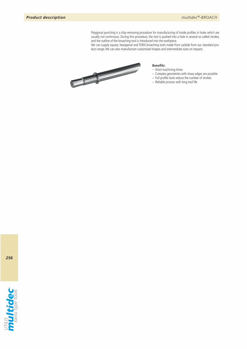
multidec®-BROACH
256
Polygonal punching is a chip-removing procedure for manufacturing of inside profiles in holes which are usually not continuous. During this procedure, the tool is pushed into a hole in several so-called strokes, and the outline of the broaching tool is introduced into the workpiece.We can supply square, hexagonal and TORX broaching tools made from carbide from our standard pro-duct range. We can also manufacture customised shapes and intermediate sizes on request.
Benefits:– Short machining times– Complex geometries with sharp edges are possible– Full profile tools reduce the number of strokes– Reliable process with long tool life
Product description
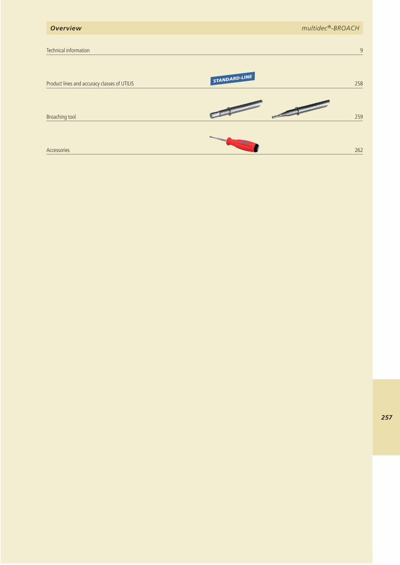
multidec®-BROACH
257
multidec®-BROACH
9 STANDARD-LINE
258
259 262
multidec®-BROACHOverview
Technical information Product lines and accuracy classes of UTILIS Broaching tool Accessories

multidec®-BROACH
258
7
– +
– +
– +
PREMIUM-LINE
VALUE-LINE
STANDARD-LINE
Product lines and accuracy classes of UTILIS
Product line Repeatability
Accuracy class of UTILIS
< 10 µm
Accuracy class of UTILIS
< 20 µm
Accuracy class of UTILIS
< 50 µm
Legend 6
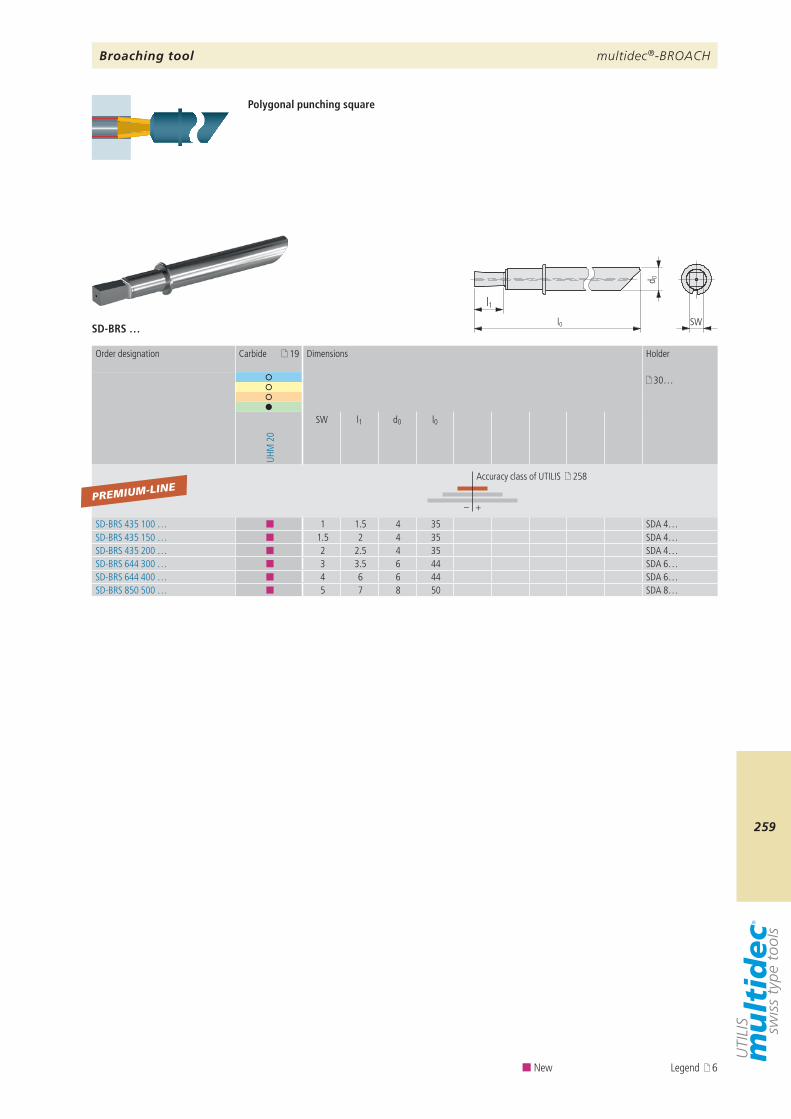
multidec®-BROACH
259
19
30…
UHM
20
SW l1 d0 l0
– +
SD-BRS 435 100 … ¢ 1 1.5 4 35 SDA 4…SD-BRS 435 150 … ¢ 1.5 2 4 35 SDA 4…SD-BRS 435 200 … ¢ 2 2.5 4 35 SDA 4…SD-BRS 644 300 … ¢ 3 3.5 6 44 SDA 6…SD-BRS 644 400 … ¢ 4 6 6 44 SDA 6…SD-BRS 850 500 … ¢ 5 7 8 50 SDA 8…
PREMIUM-LINE
SD-BRS …
l1l0
d 0
SW
Order designation Carbide Dimensions Holder
Accuracy class of UTILIS 258
Broaching tool
Polygonal punching square
¢ New Legend 6
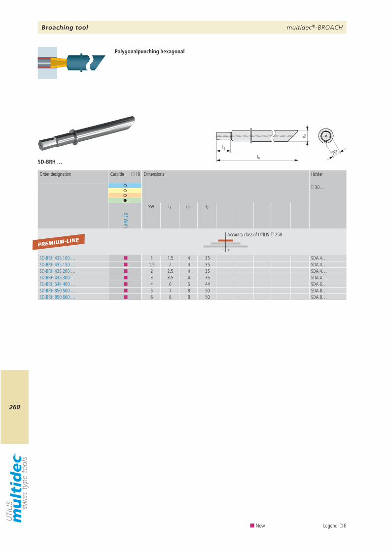
multidec®-BROACH
260
19
30…
UHM
20
SW l1 d0 l0
– +
SD-BRH 435 100 … ¢ 1 1.5 4 35 SDA 4…SD-BRH 435 150 … ¢ 1.5 2 4 35 SDA 4…SD-BRH 435 200 … ¢ 2 2.5 4 35 SDA 4…SD-BRH 435 300 … ¢ 3 3.5 4 35 SDA 4…SD-BRH 644 400 … ¢ 4 6 6 44 SDA 6…SD-BRH 850 500 … ¢ 5 7 8 50 SDA 8…SD-BRH 850 600 … ¢ 6 8 8 50 SDA 8…
PREMIUM-LINE
SD-BRH …
l1l0
d 0
SW
Order designation Carbide Dimensions Holder
Accuracy class of UTILIS 258
Broaching tool
Polygonalpunching hexagonal
¢ New Legend 6
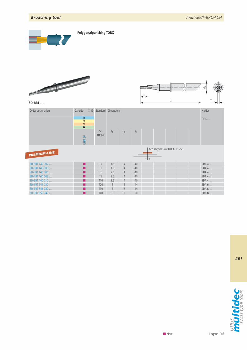
multidec®-BROACH
261
19
30…
UHM
20
ISO 10664
l1 d0 l0
– +
SD-BRT 440 002 … ¢ T2 1.5 4 40 SDA 4…SD-BRT 440 003 … ¢ T3 1.5 4 40 SDA 4…SD-BRT 440 006 … ¢ T6 2.5 4 40 SDA 4…SD-BRT 440 008 … ¢ T8 2.5 4 40 SDA 4…SD-BRT 440 010 … ¢ T10 3.5 4 40 SDA 4…SD-BRT 644 020 ¢ T20 6 6 44 SDA 6…SD-BRT 644 030 … ¢ T30 8 6 44 SDA 6…SD-BRT 850 040 … ¢ T40 9 8 50 SDA 8…
PREMIUM-LINE
SD-BRT …
l1l0
d 0
T…
Order designation Carbide Standard Dimensions Holder
Accuracy class of UTILIS 258
Broaching tool
Polygonalpunching TORX
¢ New Legend 6
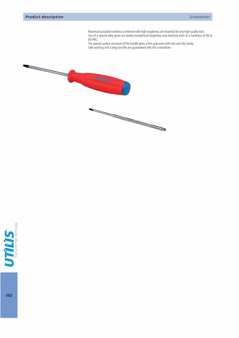
262
Screwdriver
Maximum possible hardness combined with high toughness are essential for any high quality tool.Use of a special alloy gives our blades exceptional toughness and elasticity even at a hardness of 58 to 60 HRC.The special surface structure of the handle gives a firm grip even with wet and oily hands.Safe working and a long tool life are guaranteed with this screwdriver.
Product description
263
9 264 265 265
Screwdriver
Technical information TORX TORX torque Replaceable blades
Overview
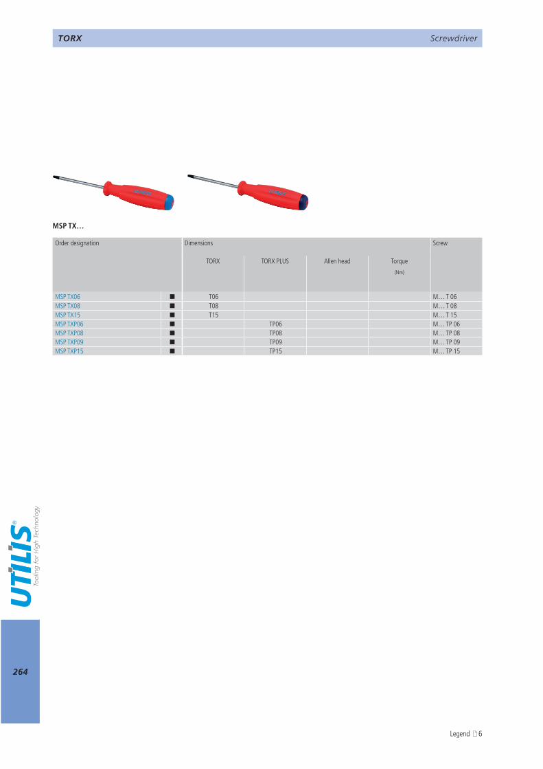
264
MSP TX…
TORX TORX PLUS
(Nm)
MSP TX06 ¢ T06 M… T 06MSP TX08 ¢ T08 M… T 08MSP TX15 ¢ T15 M… T 15MSP TXP06 ¢ TP06 M… TP 06MSP TXP08 ¢ TP08 M… TP 08MSP TXP09 ¢ TP09 M… TP 09MSP TXP15 ¢ TP15 M… TP 15
ScrewdriverTORX
Order designation Dimensions Screw
Allen head Torque
Legend 6
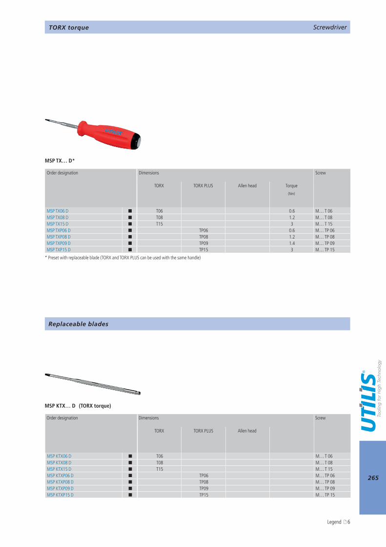
265
MSP TX… D*
MSP KTX… D
TORX TORX PLUS
(Nm)
MSP TX06 D ¢ T06 0.6 M… T 06MSP TX08 D ¢ T08 1.2 M… T 08MSP TX15 D ¢ T15 3 M… T 15MSP TXP06 D ¢ TP06 0.6 M… TP 06MSP TXP08 D ¢ TP08 1.2 M… TP 08MSP TXP09 D ¢ TP09 1.4 M… TP 09MSP TXP15 D ¢ TP15 3 M… TP 15
TORX TORX PLUS
MSP KTX06 D ¢ T06 M… T 06MSP KTX08 D ¢ T08 M… T 08MSP KTX15 D ¢ T15 M… T 15MSP KTXP06 D ¢ TP06 M… TP 06MSP KTXP08 D ¢ TP08 M… TP 08MSP KTXP09 D ¢ TP09 M… TP 09MSP KTXP15 D ¢ TP15 M… TP 15
ScrewdriverTORX torque
* Preset with replaceable blade (TORX and TORX PLUS can be used with the same handle)
Order designation Dimensions Screw
Allen head Torque
Screwdriver
Replaceable blades
Order designation Dimensions Screw
Allen head
(TORX torque)
Legend 6
266
AttentionPlease note the legend 6…
Notes

Liability/contentsContents of the catalogue is provided with largest care. We can not guarantee for the correctness, completeness and topicality of contents.
Conception/designUtilis AG, Müllheim
Composition/realizationUtilis AG, Müllheim
Photos/3DUtilis AG, Müllheim
CopyrightEach kind of the publication is inadmissible without permission of the Utilis AG.
© Copyright 2018 – UTILIS AG
Imprint

multidec®-MULTITASKPROGRAMM OF TOOL-HOLDERS FOR TURNING AND MILLING MACHINING CENTERS
THE TOOL FOR EFFICIENT TURNING OPERATIONS ON MULTITASK MACHINES FROM BUMOTEC (SERIES S181, S191, S191-V)
Utilis AG, Precision ToolsKreuzlingerstrasse 22, CH-8555 Müllheim, Switzerland
[email protected], www.utilis.comPhone 41 52 762 62 62, Fax 41 52 762 62 00+ +
UTI
LIS,
MU
LTID
EC, E
XTR
AC
T BU
MO
TEC
201
8.11
EN
– 4
0083
8
BU
MO
TEC
– 2
01
8 / 1
9 –
EN
Related Documents