Multichannel Microphone Array Design (MMAD) Multichannel sound recording Multic h a nn e l Mic r o p h o n e Array D e sign (MMAD) By Michael Williams 1 and Guillaume Le Dû 2 1 - Independent Audio Consultant, Paris, France 2 – Radio France, Paris, France Introduction Multichannel sound recording systems are as much subject to the basic rules of sound recording as any other recording system, be it monophonic or stereo- phonic. The microphone or microphone array will need to be nearer the sound source to obtain the same sound perspective compared with perception by normal hearing of the actual sound source. The perception of distance is as usual a function of direct to reverberant sound and therefore directly influenced by the directivity of the microphones used in the system. The advantage of the multichannel surround sound environment is that we are able to « envelop » the listener as much as we consider desirable. In achieving this aim we are not limited to the front facing triplet of microphones and loudspeakers to create our main sound stage, for this would create limits to the main sound stage and be little better than the traditional stereophonic reproduction. How- ever this front perception zone of about 60° seems to satisfy approximately our needs as to the angular size of the main sound stage, but with multichannel continuous sound field recording and reproduction, we have the freedom to be able to widen this sound stage if we feel the need. The stereophonic listening configuration severely limits the sound recording engineer in the reproduction of early reflections and of course in the reproduction of the surrounding reverberant sound environment (4). The process of MMAD shows how it is possible to design multichannel arrays that are capable of giving complete freedom for the sound engineer to spread the main sound stage over any desired angle, and to integrate both first reflections and reverberation and whilst maintaining their natural acoustic structure. This is another major step towards achieving perfect - reproduction of the sound environment. We must also be able to use this type of sound recording system in the recording of con- temporary music which will often make use of the surrounding sound space, and of course sound effects and ambience where sound should be localised correctly within the total surrounding sound field. But don’t be deceived; the achievement of this aim needs very careful adjustment of the parameters of the microphone array, and a clear understanding of the fundamental characteristics of each segment of the array. It must also never be forgotten that, as with stereo, the microphone array will pick up not only sound in the horizontal plane around the array, but both above and below the system (12). This sound will obviously be reproduced only in the horizontal plane of the reproduction system. We must therefore not loose sight of the fact that even multichannel surround sound recording and re- production systems still have some limitations to the impression given of natural reproduction of the total sound field. Segmentation of the Sound Field At the 91 st AES Convention (New York - 1991) in a paper entitled "Microphone Arrays for Natural Multiphony" (5), the author (Michael Williams) described the development of three microphone arrays suitable for recording/re- production systems using four, five or six channels. At this time the author considered the associated loudspeaker layout to be perfectly sym- metrical, the reproduced surround sound field being generated by loudspeakers placed on a circle divided into equal segments in the horizontal plane. Also the recording/reproduction sys- tem was based on a univalent or one to one microphone/loudspeaker relationship. The characteristics of a specific microphone array covering a given number of segments, was determined from the intersection 1

Welcome message from author
This document is posted to help you gain knowledge. Please leave a comment to let me know what you think about it! Share it to your friends and learn new things together.
Transcript
Multichannel Microphone Array Design (MMAD)
Multichannel sound recording Multichannel Microphone Array Design (MMAD)
By Michael Williams1
and Guillaume Le Dû 2
1 - Independent Audio Consultant, Paris, France 2 – Radio France, Paris, France
Introduction Multichannel sound recording systems are as much
subject to the basic rules of sound recording as any
other recording system, be it monophonic or stereo-
phonic. The microphone or microphone array will need
to be nearer the sound source to obtain the same
sound perspective compared with perception by normal
hearing of the actual sound source. The perception of
distance is as usual a function of direct to reverberant
sound and therefore directly influenced by the directivity
of the microphones used in the system. The advantage
of the multichannel surround sound environment is that
we are able to « envelop » the listener as much as we
consider desirable. In achieving this aim we are not
limited to the front facing triplet of microphones and
loudspeakers to create our main sound stage, for this
would create limits to the main sound stage and be little
better than the traditional stereophonic reproduction.
How- ever this front perception zone of about 60°
seems to satisfy approximately our needs as to the
angular size of the main sound stage, but with
multichannel continuous sound field recording and
reproduction, we have the freedom to be able to widen
this sound stage if we feel the need.
The stereophonic listening configuration severely limits
the sound recording engineer in the reproduction of
early reflections and of course in the reproduction of the
surrounding reverberant sound environment (4). The
process of MMAD shows how it is possible to design
multichannel arrays that are capable of giving complete
freedom for the sound engineer to spread the main
sound stage over any desired angle, and to integrate
both first reflections and reverberation and whilst
maintaining their natural acoustic structure. This is
another major step towards achieving perfect -
reproduction of the sound environment. We must
also be able to use this type of sound recording
system in the recording of con- temporary music
which will often make use of the surrounding
sound space, and of course sound effects and
ambience where sound should be localised
correctly within the total surrounding sound field.
But don’t be deceived; the achievement of this aim
needs very careful adjustment of the parameters of
the microphone array, and a clear understanding
of the fundamental characteristics of each
segment of the array. It must also never be
forgotten that, as with stereo, the microphone
array will pick up not only sound in the horizontal
plane around the array, but both above and below
the system (12). This sound will obviously be
reproduced only in the horizontal plane of the
reproduction system. We must therefore not
loose sight of the fact that even multichannel
surround sound recording and re- production
systems still have some limitations to the
impression given of natural reproduction of the
total sound field.
Segmentation of the Sound Field
At the 91st
AES Convention (New York - 1991) in a
paper entitled "Microphone Arrays for Natural
Multiphony" (5), the author (Michael Williams)
described the development of three microphone
arrays suitable for recording/re- production systems
using four, five or six channels. At this time the author
considered the associated loudspeaker layout to be
perfectly sym- metrical, the reproduced surround sound
field being generated by loudspeakers placed on a circle
divided into equal segments in the horizontal plane. Also
the recording/reproduction sys- tem was based on a
univalent or one to one microphone/loudspeaker
relationship. The characteristics of a specific
microphone array covering a given number of
segments, was determined from the intersection
1
Multichannel Microphone Array Design (MMAD)
of the physics of the microphone array with the
psychoacoustics of the listening configuration. This
approach was conceived, for the four-channel system,
purely as an extension and improvement of the
original Quadraphonic Recording/Reproduction
System, and it seems, was somewhat in advance of
the multichannel systems now required.
Although a similar approach by segmentation of the
sound field is used in Multichannel Micro- phone
Array Design (MMAD) (8), almost complete
freedom can be obtained in the relation to the
physical angle between the microphones with
respect to the corresponding segment coverage
angle. A detailed analysis will show how to “link”
segments without overlap, and obtain a smooth
continuous reproduction of the total sound field.
The standardisation in the context of multichannel
reproduction in relation to surround sound for audio-
visual applications has since modified considerably
the layout of the sound field segments. This,
together with an ever-increasing interest in the use
of multichannel systems for the reproduction of
music as a purely audio media, has shown the need
for a clear and unambiguous analysis of the
psychoacoustics of reproduction in a multichannel
environment, in order to help in the development of
microphone arrays that can meet the need for
specific sound field segment pick-up and
reproduction.
In Stereophony, considerable use has been made of
Intensity Difference, Time Difference and combined
Intensity/Time Difference systems to produce
reasonably satisfactory microphone systems for
the recording and reproduction of the sound field. In
previous AES papers (1) (2) (3) (4) (5) (6) the author
has shown how a multiplicity of dual microphone
arrays can be developed to en- able the sound
recording engineer to choose the best
configuration for optimum stereophonic results in
a given set of conditions. This same approach has
been applied to microphone arrays for
multichannel systems.
It is a convention established in a previous AES
Convention papers (1) (2) that the Stereophonic
Recording Angle is always specified for instance as
+/- 50° to avoid confusion with the angle between
the microphones. However in the case of
Multichannel Microphone Arrays we no longer
have a symmetrical recording/reproduction
sound stage in relation to each of the array
segments, so it would seem necessary to change
terminology and use the idea of Coverage Angle to
mean the total coverage of the Stereophonic
Recording Angle of a single pair of microphones
making up part of the total Multichannel Array. In
the above example the SRA of +/- 50° becomes a
Coverage Angle of 100°.
Back to Basics It should not come as any surprise to the initiated
that we must first deepen our knowledge of the
characteristics of a simple pair of microphones,
reproduced evidently by two loudspeakers. In the
context of stereophonic reproduction, left/right
symmetry of the reproduced sound field is, in
general, obviously desirable. The sound field
reproduced by the loudspeakers can be either
smaller or larger than the physical angle between
the axis of directivity of the microphones, and
disposed usually symmetrically on each side of the
physical axis of the pair of microphones.
However in the design of multichannel micro- phone
arrays we must have complete control over the
angular offset of the reproduced segments of the
sound field in relation to the axis of symmetry of the
microphone pair covering each specific segment. In
the design of the front facing triplet of microphones
covering the left and right front segments, we must
be able to offset the reproduced sound field
segments so that the side limits of the left and
right sound fields correspond to the axis of the front
facing centre microphone. For the lateral segments
however we need to be able to rotate freely the
coverage of the side segments, without any
coincidence between the physical axis of the
microphones and the limits of each of the sound
field segments. And finally, for the back segment we
return to the simple symmetrical segment as used
in stereophony.
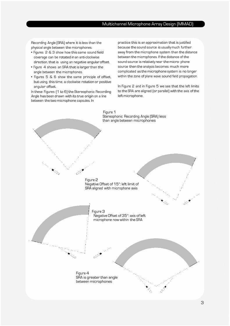
Offset and Linking The application of Offset is illustrated in Figures 1
to 6.
• Figure 1 shows the standard Stereophonic
2
Multichannel Microphone Array Design (MMAD)
Recording Angle (SRA) where it is less than the
physical angle between the microphones.
• Figures 2 & 3 show how this same sound field
coverage can be rotated in an anti-clockwise
direction, that is using an negative angular offset.
• Figure 4 shows an SRA that is larger than the
angle between the microphones.
• Figures 5 & 6 show the same principle of offset,
but using, this time, a clockwise rotation or positive
angular offset.
In these Figures (1 to 6) the Stereophonic Recording
Angle has been drawn with its true origin on a line
between the two microphone capsules. In
practice this is an approximation that is justified
because the sound source is usually much further
away from the microphone system than the distance
between the microphones. If the distance of the
sound source is relatively near the micro- phone
source then the analysis becomes much more
complicated as the microphone system is no longer
within the zone of plane wave sound field propagation.
In Figure 2 and in Figure 5 we see that the left limits
to the SRA are aligned (or parallel) with the axis of the
left microphone.
Figure 1 Stereophonic Recording Angle (SRA) less than angle between microphones
Figure 2 Negative Offset of 15°: left limit of SRA aligned with microphone axis
Figure 3 Negative Offset of 35°: axis of left microphone now within the SRA
Figure 4 SRA is greater than angle between microphones
3
Multichannel Microphone Array Design (MMAD)
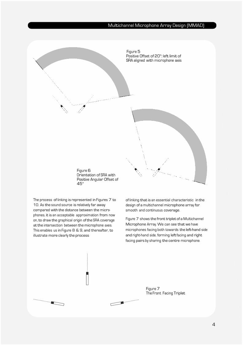
Figure 5 Positive Offset of 20°: left limit of SRA aligned with microphone axis
Figure 6 Orientation of SRA with Positive Angular Offset of 45°
The process of linking is represented in Figures 7 to
10. As the sound source is relatively far away
compared with the distance between the micro-
phones, it is an acceptable approximation from now
on, to draw the graphical origin of the SRA coverage
at the intersection between the microphone axes.
This enables us in Figure 8 & 9, and thereafter, to
illustrate more clearly the process
of linking that is an essential characteristic in the
design of a multichannel microphone array for
smooth and continuous coverage.
Figure 7 shows the front triplet of a Multichannel
Microphone Array. We can see that we have
microphones facing both towards the left-hand side
and right-hand side, forming left facing and right
facing pairs by sharing the centre microphone.
Figure 7 The Front Facing Triplet
4
Multichannel Microphone Array Design (MMAD)
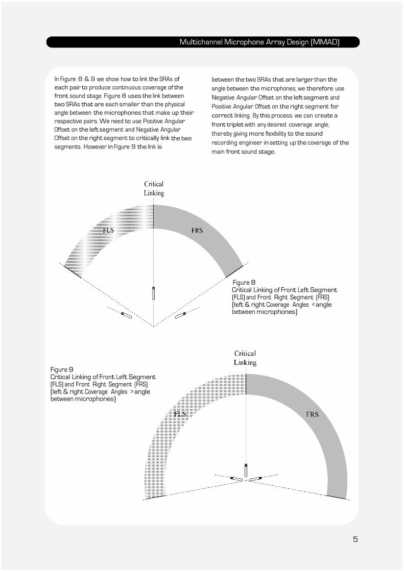
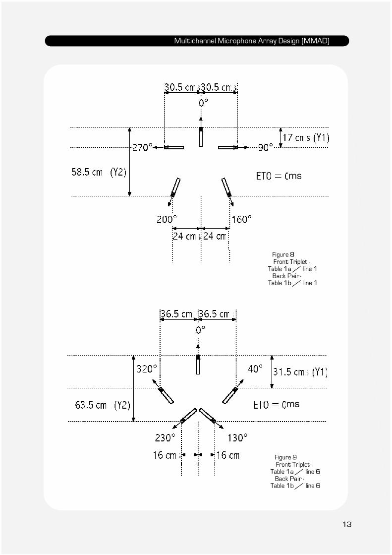
In Figure 8 & 9 we show how to link the SRAs of
each pair to produce continuous coverage of the
front sound stage. Figure 8 uses the link between
two SRAs that are each smaller than the physical
angle between the microphones that make up their
respective pairs. We need to use Positive Angular
Offset on the left segment and Negative Angular
Offset on the right segment to critically link the two
segments. However in Figure 9 the link is
between the two SRAs that are larger than the
angle between the microphones, we therefore use
Negative Angular Offset on the left segment and
Positive Angular Offset on the right segment for
correct linking. By this process we can create a
front triplet with any desired coverage angle,
thereby giving more flexibility to the sound
recording engineer in setting up the coverage of the
main front sound stage.
Figure 8 Critical Linking of Front Left Segment (FLS) and Front Right Segment (FRS) (left & right Coverage Angles < angle between microphones)
Figure 9 Critical Linking of Front Left Segment (FLS) and Front Right Segment (FRS) (left & right Coverage Angles > angle between microphones)
5

Multichannel Microphone Array Design (MMAD)
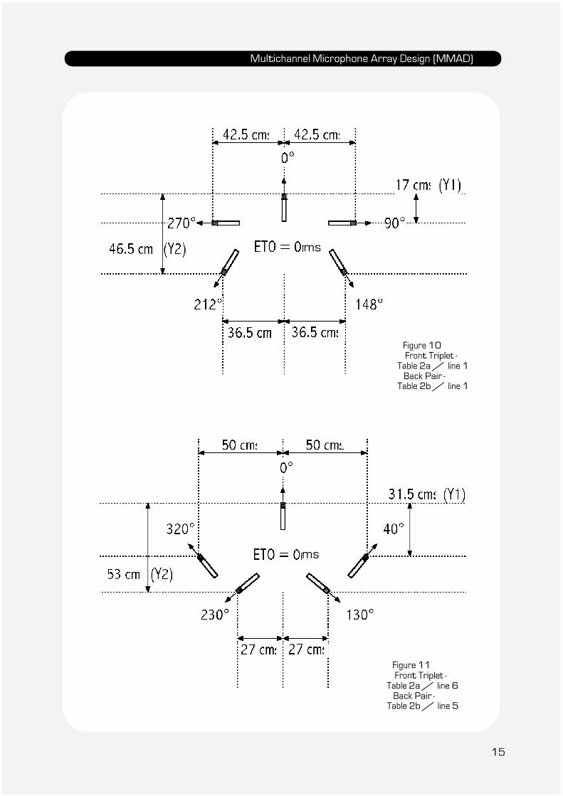
Figure 10 shows how this process of linking is
applied for the complete Multichannel Microphone
Array. Only the front facing centre microphone is
aligned with the linking of two segments i.e. the
link between the Front Left Segment (FLS) and the
Front Right Segment (FRS). The Back Segment (BS) is
usually symmetrical with respect to the back axis of
the system.
Figure 10 Critical linking between all segments of a Multichannel Microphone Array
Intensity and Time Offset
Generation
The method used to produce this offset technique is
in fact remarkably simple, both in theory and
practice. The difficulty comes in the choice of specific
offsets so that « critical linking » is obtained, and
smooth and continuous sound field reproduction is
achieved. Basically there are four different types of
offset that we can apply:
• Electronic Intensity Offset – addition of a
constant Intensity Difference to the
Intensity/Time Difference function between two
microphones
• Electronic Time Offset – addition of a constant
Time Difference to the Intensity/Time
Difference function between two microphones
• Microphone Position Intensity Offset
• Microphone Position Time Offset
These last two offsets are one and the same, as it
is just a question of one type of offset relative to the
other. By creating a Microphone Position Intensity
Offset in one direction, it is equivalent to creating a
Microphone Position Time Off- set in the other
direction.
6
Multichannel Microphone Array Design (MMAD)
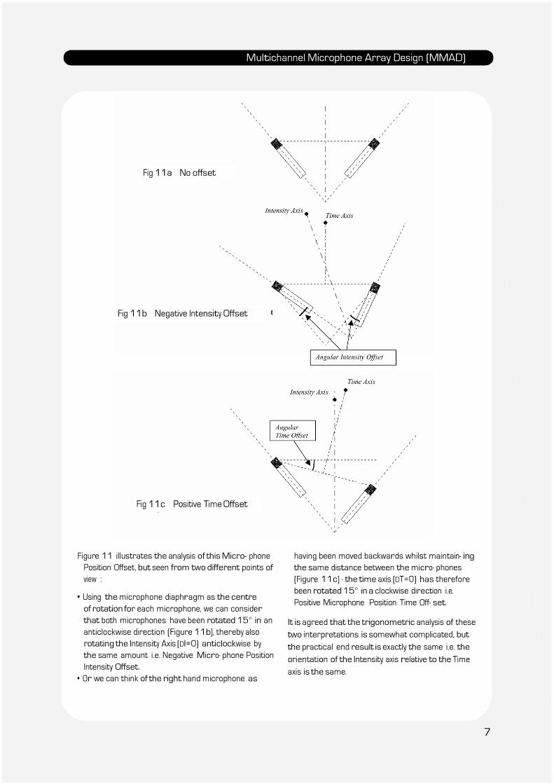
Fig 11a No offset
Fig 11b Negative Intensity Offset
Fig 11c Positive Time Offset
Figure 11 illustrates the analysis of this Micro- phone
Position Offset, but seen from two different points of
view :
• Using the microphone diaphragm as the centre
of rotation for each microphone, we can consider
that both microphones have been rotated 15° in an
anticlockwise direction (Figure 11b), thereby also
rotating the Intensity Axis (DI=0) anticlockwise by
the same amount i.e. Negative Micro- phone Position
Intensity Offset.
• Or we can think of the right hand microphone as
having been moved backwards whilst maintain- ing
the same distance between the micro- phones
(Figure 11c) - the time axis (DT=0) has therefore
been rotated 15° in a clockwise direction i.e.
Positive Microphone Position Time Off- set.
It is agreed that the trigonometric analysis of these
two interpretations is somewhat complicated, but
the practical end result is exactly the same i.e. the
orientation of the Intensity axis relative to the Time
axis is the same.
7
Multichannel Microphone Array Design (MMAD)
There is however a subtle difference between
Electronic Offset and Microphone Position Offset.
• Electronic Offset is simply the addition of a constant
value of Intensity Difference or Time Difference to the
Intensity/Time function of a pair of microphones
covering a particular segment.
• Microphone Position Offset is created by changing the
physical position of the microphones forming the
pair, thereby creating an angular difference between
the Intensity and Time axes.
Let us be clear on the convention that has been
adopted for Positive and Negative Offsets:
Positive Offset is defined as that offset which
produces a rotation of the Coverage Angle in a
clockwise direction.
• This is obtained in the case of a Positive Electronic
Time Offset by introducing a delay in the right hand
microphone in relation to the left hand microphone.
• Similarly with Positive Electronic Intensity Offset the
right hand microphone is attenuated in relation to
the left.
• With Positive Microphone Position Time Offset the
right hand microphone is rotated clockwise (i.e.
backwards) using the centre of the left micro- phone
diaphragm as the centre of rotation whilst
maintaining the same distance between the
microphones and angle between the axes of the
microphones.
Each of these different positive offsets will produce a
shift in their respective Intensity/Time function
graphs either to the left for Positive Time Offsets, or
downwards for Positive Intensity Offsets. This can be a
little disconcerting at first, however the sound position
co-ordinates show the relative position of the Coverage
Angle and this leaves no room for ambiguity
Further detailed analysis of different offset
functions can be found in AES preprint 4997 (8).
The process of Multichannel Microphone Array De-
sign is highly complex, due to the interaction of the
many parameters that are involved. It would seem
almost impossible to envisage undertaking the
complete multichannel design process just before
the beginning of a recording session. Unfortunately
this is the moment when the sound recording
engineer is more or less in possession of the
complete range of characteristics of the sound
field to be recorded. This rest of this document will
present a quick reference guide to some
different Multichannel Microphone Array
configurations to assist the sound engineer in
quickly choosing a system adapted to each
particular circumstance. These Multichannel
Microphone Array configurations were first
presented in AES preprint (11).
All systems described present good Critical Linking;
i.e. the reproduction of the sound field is continuous
without any « holes » or « overlaps ». However as a
complete description of each sys- tem would
require as many pages as there are systems, it
was considered more reasonable to present the
characteristics of each of the a rays grouped within
a table covering each specific value of Front Triplet
Coverage. Within each of these Front Triplet
Coverage values a range of possible combinations
are suggested. In general Microphone Position
Offset is used to obtain Critical Linking of the Front
Triplet Segments whereas Electronic Time Offset is
normally required to obtain Critical Linking of the
Lateral Segments. Microphone Position Offset, as
its name implies, is obtained purely by the correct
position and orientation of the micro- phones in the
array, however, Electrical Time Offset needs specific
time delays to be introduced into certain channels.
The sound recording engineer does not always have
the possibility to adjust Electrical Time Offset with
the equipment available for a recording session. For
this reason a few selected arrays have been de-
scribed which have Natural Critical Linking, i.e. the
parameters of the array have been chosen so that
no electrical offset is necessary to obtain Critical
Linking. The orientation of each microphone and
their corresponding « X » and « Y » co-ordinates are
the only parameters that have to be set up to
obtain Critical Linking with these specific arrays.
The concept of Critical Linking means that the
impression of a continuous sound field is
reproduced no matter what the orientation of the
listener within the loudspeaker set-up. This allows -
8
Multichannel Microphone Array Design (MMAD)
a certain freedom of rotational movement of the
head, but does not obviously change the need for the
listener to be in the centre of the loudspeaker
system, commonly called « the sweet spot ». But « Oh!
How sweet » is this experience with a good recording
made with a correctly designed Multi- channel
Microphone Array!
MMA design procedure
General Overall Strategy
As with the choice of a dual microphone array for
stereophonic sound recording, the first stage of array
design is to determine the probable position of the
microphone system, and therefore to measure the
angle of the sound source as « seen » by the
microphone array. Details for the construction of a
suitable measuring instrument are given in the
document “St Zoom” on this CD-ROM. With a stereo-
phonic microphone array the Stereophonic Recording
Angle (SRA) is chosen according to the amount of «
side room » to be left on either side of the sound
source. In general a small musical sound source such
as a quartet needs an SRA that is about 10% wider
than the actual sound source (the extra 10% on each
side is called the « side room »). However for a wider
sound source, such as a Symphony Orchestra, the SRA
is usually about10% smaller than the total sound
stage. This enables better resolution in the centre
part of the orchestra, but obviously to the detriment of
the extremities of the orchestra, which will become
somewhat crushed onto the left and right loud-
speakers in stereophonic reproduction.
With the Multichannel Microphone Array we have the
added advantage of a wider reproduction stage. We
are therefore not limited to the 60° of stereo- phonic
reproduction. Although the complete use of the side
segments for direct sound is not advisable due to the
progressively worsening localisation characteristics
on the side, it is nevertheless possible to exploit the
sound reproduction further than the « 30° + 30° »
defined by the front three loud- speakers. A 10° or 20°
spread of the sound source into the lateral segments
is possible, with the added advantage of a better feeling
of envelopment of the listener and, of course,
considerably better reproduction of early reflection
groups. However it remains to be seen as to precisely
how much more spread is possible with a wide sound
source and also whether we still need to stay within
the front 60° with the smaller sources. In practice
this obviously means that we need to use a Multi-
channel Microphone Array that allows us to fully
exploit the recording and reproduction
characteristics of the lateral segments.
In the design of a dual microphone pair for stereo-
phonic sound recording complete freedom exists to
choose any combination of distance and angle, for
the desired Coverage. This allows the sound engineer
to choose any system from coincident directional
microphones through hybrid combinations of
distance and angle to the purely time de- pendent
spaced pair of omnidirectional micro- phones. In the
multichannel array design a purely intensity
dependent system is not feasible if we are looking for
a Critically Linked surround sound system. However
careful examination of the multi- channel microphone
array configurations presented in the tables will
demonstrate that it is possible to select systems
that have either Time or Intensity Dominance
according to the options chosen in design. It remains
to be seen whether a Time Dominant, or Intensity
Dominant system, is preferable for better
localisation in the lateral segments.
The completely «surround sound» characteristics of
natural reverberation mean that a continuous
sound field pick-up around the array becomes a
necessity. Attention to Critical Linking therefore
becomes of paramount importance and must
therefore be integrated into the total process of
Multichannel Microphone Array Design presented
in this document.
The majority of musical sound recording situations
that we encounter concern the reproduction of a
limited sound stage as seen in the concert hall or
theatre. The research for a satisfactory re-
production of the completely surrounding direct
sound source, although technically very challenging, is
not part of our daily bread.
9
Multichannel Microphone Array Design (MMAD)
In general the Multichannel Microphone Array has
a considerable wing span somewhat like the proverbial
« albatross ». However careful analysis of the many
arrays presented in this paper will show that this is
not always the case. There are also some
circumstances, for instance when a minimum of
physical size is important, in which case it is necessary
to neglect the reproduction characteristics of the
lateral segments. But we are perforce limited
to the 60° of the front sound stage (as with the
standard stereophonic sound stage) created by the
front three loudspeakers, and the far from
satisfactory 140° of the back segment reproduction.
How- ever in this document we are only concerned
with good continuous reproduction of the total
surround sound environment.
This still leaves us with the first major decision as to
what coverage angle to adopt relative to the direct
sound from the sound source. There are no rules as
to how to go about setting up a micro- phone array
for multichannel sound recording system. Each sound
recording engineer will have his own ideas and
preferences and this is of course part of the art of
sound recording. However here are some guidelines
as to a possible procedure:
a) Determine the probable position of the micro-
phone system
b) Decide on the required reproduction angle of the
direct sound source. This will determine the
Coverage Angle of the Front Triplet Array.
Remember that the Front Triplet Coverage will only
be reproduced between the front three loud-
speakers. Further “spread” will concern the side
segments. If the Front Triplet Coverage angle is
smaller than the sound source, then in
reproduction there will be spread into the side
segments. If the Front Triplet Coverage is wider
than the sound source, then the reproduced sound
source will be within the front sound stage
created by the front three loudspeakers.
c) Decide on the relative balance between Back
Segment and Lateral Segment Coverage. This will
determine the Back Pair Coverage
characteristics.
d) Choose your own preference concerning
Intensity/Hybrid/Time Dominance. It is obviously
physically impossible to have Intensity or Time
Dominance for both the Back Segment and the
Lateral Segments; they will usually be
complimentary. Both can of course be Hybrid
combination (equal dominance between Time
and Intensity).
e) Introduce, if needed, the correct Electronic
Offset values between the front Triplet and
the Back Pair.
f) Listen to the result! and start again until
satisfied that you have achieved the optimum
result in the circumstances.
Critical Linking with Electronic Off- set versus Natural Critical Linking The various techniques needed to obtain Critical
Linking have been described in previous AES
preprints (9) (11) under chapters concerning
Microphone Position Time Offset (MPTO), Electronic
Time Offset (ETO) and Electronic Intensity Offset (EIO). Of
these different types of offset, MPTO is of course
the easiest to generate, as it is obtained simply by
the physical position and orientation of the
microphone. ETO however re- quires the fine
adjustment of Time Delay between the Front Triplet
and the Back Pair, a facility that is not always
available on the standard mixing desk or even in
post production with an Audio Workstation. On the
other hand EIO is just a matter of introducing the
correct constant Intensity Difference, into the
microphone array within the Front Triplet or
between the Front Triplet and Back Pair (EIO can be
used to generate Critical Linking either in the design
of the Front Triplet Coverage or in the Lateral
Segment Coverage). However it must be said that
the range of Critical Linking that can be obtained
with EIO processing is very much more limited than
with ETO. Also the difference in level between each
component of the array may produce an undesirable
imbalance between different parts of the Array
Coverage. Detailed consideration of the design of
this type of array using EIO is outside the scope of
this paper.
Although « Natural Critical Linking » considerably
limits the choice in array design, it has a
considerable advantage in that no electronic
manipulation of Segment Coverage is required.
Critical Linking is obtained purely by microphone
position and orientation, not only for the Front
10
Multichannel Microphone Array Design (MMAD)
Triplet, but also between the Front Triplet, the
Lateral Segment and the Back Pair Coverage. This
type of array is operational without any further
signal processing. Microphone signals can therefore
be recorded direct to any 5 channel recording
system without the intervention of a more complex
sound mixing or signal processing stage. This is
obviously an important factor when doing « on-
location » recording with limited studio facilities.
Tables 1, 2 & 3 show three sets of operational
Multichannel Microphone Arrays where no electrical
offset is needed. The combination of « Table 1a
line 3 » together with « Table 1b line 3 » has already
been presented at a paper given at the 91st
AES
Convention in New York (5) some 10 years ago! But
this was before the seeds of the multichannel
market were sown.
Table presentation
Seven table groups are presented covering over
220 possible microphone array configurations. The
Front Triplet design is shown in each
Table « a », whilst Table « b » describes the
corresponding Back Pair and Lateral Segment
Cover- age parameters. It is a remarkable feature of
the design process that within the same table
number, a specific combination chosen from Table
« b » will automatically be Critically Linked with any
combination chosen from Table « a » on condition
that the correct ETO has been applied. The Linking
function depends on the Coverage Angle and not on
the angle between the microphones. Variations of
distance and angle used to obtain the same
Coverage Angle will automatically Critically Link to
neighbouring segments. Each « Table- set : a & b » will
therefore cover between 30 and 36 possible
microphones arrays (except for table 3 where
Critical Linking is very limited and only one Back Pair
configuration is shown). Two examples of microphone
lay-out are given in the figures immediately after each
table-set.
MMAD – First stage - front triplet
design
The first stage in design (as explained above) is
the choice of microphone array position, and
thereafter the Front Triplet Coverage. A wide
range of Front Triplet Coverage values are
presented in Tables 4 to 8, allowing the sound
engineer to adjust the Front Triplet Coverage from
a maximum of « 90° + 90° » to a minimum of
« 50° + 50° ». Critical Linking is almost impossible
for smaller values of Front Triplet Coverage.
MMAD – Second stage – back pair The second stage in design is to determine the de-
sired Back Segment Coverage. Again a wide
choice of Coverage has been presented, from 90°
to 40°, allowing the sound engineer to optimise the
reproduction of the back segment that usually covers
the reverberant field. In most cases it is better not
to overload back segment coverage as this can be
somewhat disconcerting when reproduced in the
segment behind the listener. This means that in
practice it is better to choose the lower values of
Back Segment Coverage that will be spread out over
the 140° of back segment re- production and of
course includes considerable Angular Distortion
(10).
MMAD – Third stage – lateral
segments
The third stage concerning the Lateral Segment
Coverage is usually considered to be the Coverage of
the remaining surround sound-field angle, and will be
conditioned by the distance between the Front
Triplet and the Back Pair. Critical Linking will be
obtained by the introduction of the correct amount
of Electronic Time Offset, unless of course a
combination producing Natural Critical Linking has
been selected.
Other possible configurations
For the sake of simplicity and quick reference, only
certain specific configurations have been presented
in the tables, but of course there are a multitude of
other configurations possible within the continuum
of possible microphone distance and angle. However
from the operational point of view, the large range of
choice, presented in tables 1 to 8, should be enough
to satisfy most sound recording situations.
11
Multichannel Microphone Array Design (MMAD)
Microphone directivity As with the design of a dual microphone stereo-
phonic array, we are not restricted to the use of
cardioid microphones. It is the intention of the
authors of this document to present, in future AES
papers, not only a choice of microphone arrays
using other first order directivity patterns, but
also to suggest a wide range of possible hybrid
arrays using different directivity patterns for
each part of the array structure.
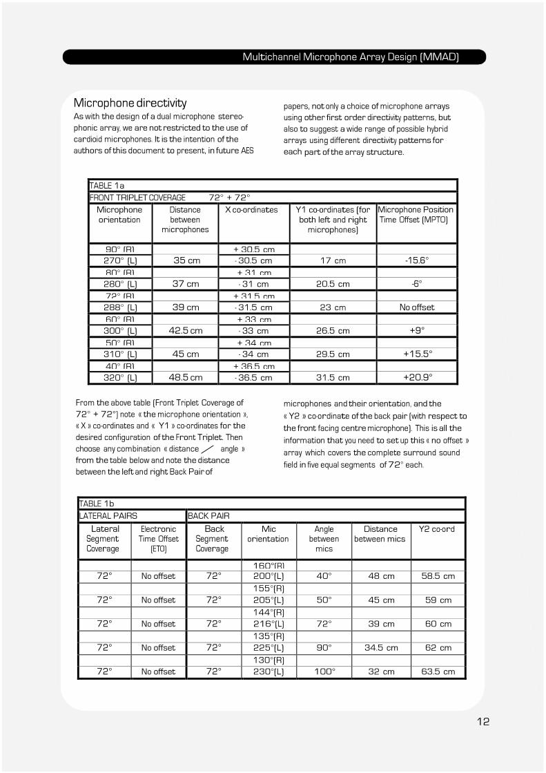
TABLE 1a FRONT TRIPLET COVERAGE 72° + 72° Microphone
orientation Distance between
microphones
X co-ordinates Y1 co-ordinates (for
both left and right microphones)
Microphone Position Time Offset (MPTO)
90° (R) + 30.5 cm 270° (L) 35 cm - 30.5 cm 17 cm -15.6°
80° (R) + 31 cm 280° (L) 37 cm - 31 cm 20.5 cm -6°
72° (R) + 31.5 cm 288° (L) 39 cm - 31.5 cm 23 cm No offset
60° (R) + 33 cm 300° (L) 42.5 cm - 33 cm 26.5 cm +9°
50° (R) + 34 cm 310° (L) 45 cm - 34 cm 29.5 cm +15.5°
40° (R) + 36.5 cm 320° (L) 48.5 cm - 36.5 cm 31.5 cm +20.9°
From the above table (Front Triplet Coverage of
72° + 72°) note « the microphone orientation »,
« X » co-ordinates and « Y1 » co-ordinates for the
desired configuration of the Front Triplet. Then
choose any combination « distance / angle »
from the table below and note the distance
between the left and right Back Pair of
microphones and their orientation, and the
« Y2 » co-ordinate of the back pair (with respect to
the front facing centre microphone). This is all the
information that you need to set up this « no offset »
array which covers the complete surround sound
field in five equal segments of 72° each.
TABLE 1b LATERAL PAIRS BACK PAIR
Lateral Segment
Coverage
Electronic Time Offset
(ETO)
Back Segment
Coverage
Mic orientation
Angle between mics
Distance between mics
Y2 co-ord
160°(R) 72° No offset 72° 200°(L) 40° 48 cm 58.5 cm
155°(R) 72° No offset 72° 205°(L) 50° 45 cm 59 cm
144°(R) 72° No offset 72° 216°(L) 72° 39 cm 60 cm
135°(R) 72° No offset 72° 225°(L) 90° 34.5 cm 62 cm
130°(R) 72° No offset 72° 230°(L) 100° 32 cm 63.5 cm
12
Multichannel Microphone Array Design (MMAD)
ms
Figure 8 Front Triplet -
Table 1a / line 1 Back Pair -
Table 1b / line 1
ms
Figure 9 Front Triplet -
Table 1a / line 6 Back Pair -
Table 1b / line 6
13
Multichannel Microphone Array Design (MMAD)
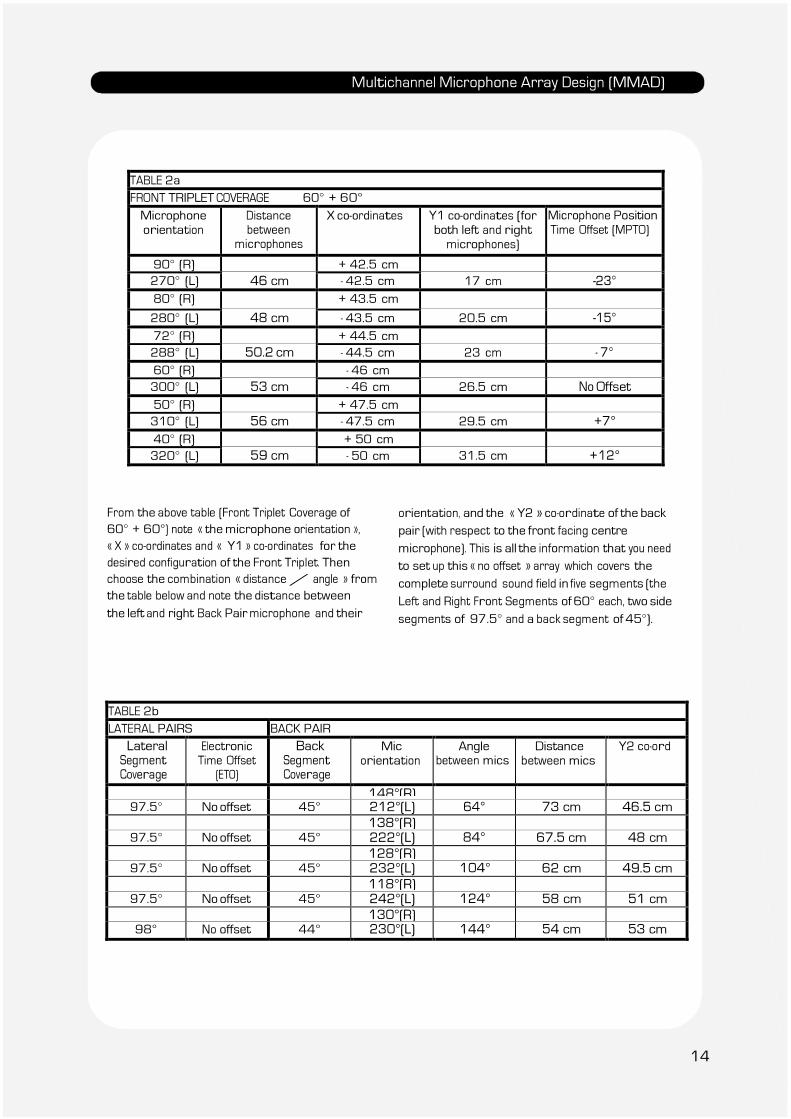
TABLE 2a FRONT TRIPLET COVERAGE 60° + 60°
Microphone orientation
Distance between
microphones
X co-ordinates Y1 co-ordinates (for both left and right
microphones)
Microphone Position Time Offset (MPTO)
90° (R) + 42.5 cm 270° (L) 46 cm - 42.5 cm 17 cm -23°
80° (R) + 43.5 cm 280° (L) 48 cm - 43.5 cm 20.5 cm -15°
72° (R) + 44.5 cm 288° (L) 50.2 cm - 44.5 cm 23 cm - 7°
60° (R) - 46 cm 300° (L) 53 cm - 46 cm 26.5 cm No Offset
50° (R) + 47.5 cm 310° (L) 56 cm - 47.5 cm 29.5 cm +7°
40° (R) + 50 cm 320° (L) 59 cm - 50 cm 31.5 cm +12°
From the above table (Front Triplet Coverage of
60° + 60°) note « the microphone orientation »,
« X » co-ordinates and « Y1 » co-ordinates for the
desired configuration of the Front Triplet. Then
choose the combination « distance / angle » from
the table below and note the distance between
the left and right Back Pair microphone and their
orientation, and the « Y2 » co-ordinate of the back
pair (with respect to the front facing centre
microphone). This is all the information that you need
to set up this « no offset » array which covers the
complete surround sound field in five segments (the
Left and Right Front Segments of 60° each, two side
segments of 97.5° and a back segment of 45°).
TABLE 2b LATERAL PAIRS BACK PAIR
Lateral Segment
Coverage
Electronic Time Offset
(ETO)
Back Segment
Coverage
Mic orientation
Angle between mics
Distance between mics
Y2 co-ord
148°(R) 97.5° No offset 45° 212°(L) 64° 73 cm 46.5 cm
138°(R) 97.5° No offset 45° 222°(L) 84° 67.5 cm 48 cm
128°(R) 97.5° No offset 45° 232°(L) 104° 62 cm 49.5 cm
118°(R) 97.5° No offset 45° 242°(L) 124° 58 cm 51 cm
130°(R) 98° No offset 44° 230°(L) 144° 54 cm 53 cm
14
Multichannel Microphone Array Design (MMAD)
ms
Figure 10 Front Triplet -
Table 2a / line 1 Back Pair -
Table 2b / line 1
ms
Figure 11 Front Triplet -
Table 2a / line 6 Back Pair -
Table 2b / line 5
15
Multichannel Microphone Array Design (MMAD)
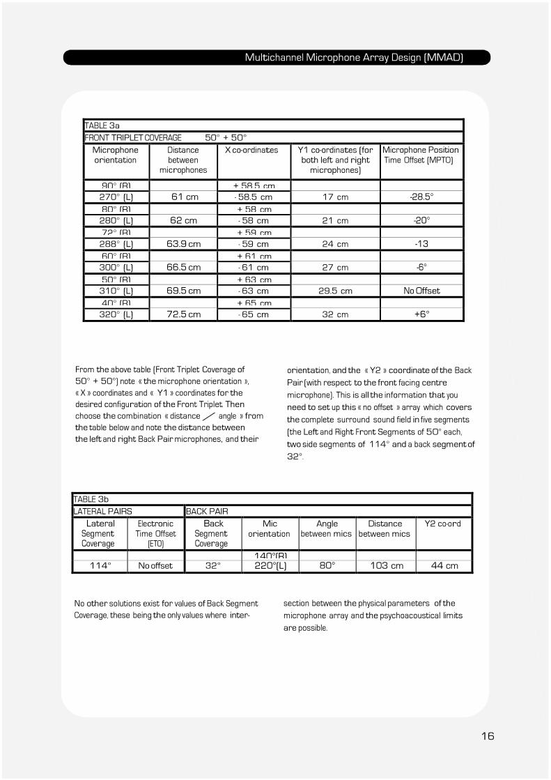
TABLE 3a FRONT TRIPLET COVERAGE 50° + 50° Microphone orientation
Distance between
microphones
X co-ordinates Y1 co-ordinates (for both left and right microphones)
Microphone Position
Time Offset (MPTO)
90° (R) + 58.5 cm 270° (L) 61 cm - 58.5 cm 17 cm -28.5°
80° (R) + 58 cm 280° (L) 62 cm - 58 cm 21 cm -20°
72° (R) + 59 cm 288° (L) 63.9 cm - 59 cm 24 cm -13
60° (R) + 61 cm 300° (L) 66.5 cm - 61 cm 27 cm -6°
50° (R) + 63 cm 310° (L) 69.5 cm - 63 cm 29.5 cm No Offset
40° (R) + 65 cm 320° (L) 72.5 cm - 65 cm 32 cm +6°
From the above table (Front Triplet Coverage of
50° + 50°) note « the microphone orientation »,
« X » coordinates and « Y1 » coordinates for the
desired configuration of the Front Triplet. Then
choose the combination « distance / angle » from
the table below and note the distance between
the left and right Back Pair microphones, and their
orientation, and the « Y2 » coordinate of the Back
Pair (with respect to the front facing centre
microphone). This is all the information that you
need to set up this « no offset » array which covers
the complete surround sound field in five segments
(the Left and Right Front Segments of 50° each,
two side segments of 114° and a back segment of
32°.
TABLE 3b LATERAL PAIRS BACK PAIR
Lateral Segment
Coverage
Electronic Time Offset
(ETO)
Back Segment
Coverage
Mic
orientation Angle
between mics Distance
between mics Y2 co-ord
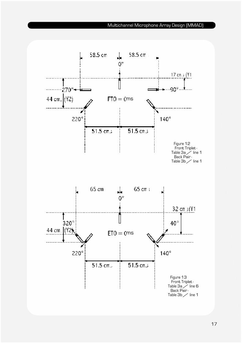
140°(R) 114° No offset 32° 220°(L) 80° 103 cm 44 cm
No other solutions exist for values of Back Segment
Coverage, these being the only values where inter-
section between the physical parameters of the
microphone array and the psychoacoustical limits
are possible.
16
Multichannel Microphone Array Design (MMAD)
ms
Figure 12 Front Triplet -
Table 3a / line 1 Back Pair -
Table 3b / line 1
ms
Figure 13 Front Triplet -
Table 3a / line 6 Back Pair -
Table 3b / line 1
17
Multichannel Microphone Array Design (MMAD)
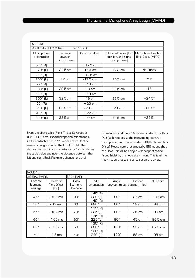
TABLE 4a
FRONT TRIPLET COVERAGE 90° + 90°
Microphone orientation
Distance between
microphones
X co-ordinates Y1 co-ordinates (for both left and right microphones)
Microphone Position Time Offset (MPTO)
90° (R) + 17.3 cm 270° (L) 24.5 cm - 17.3 cm 17.3 cm No Offset
80° (R) + 17.5 cm 280° (L) 27 cm - 17.5 cm 20.5 cm +9.2°
72° (R) + 18 cm 288° (L) 29.5 cm - 18 cm 23.5 cm +18°
60° (R) + 19 cm 300° (L) 32.5 cm - 19 cm 26.5 cm +24.5°
50° (R) + 20 cm 310° (L) 35.5 cm - 20 cm 29 cm +30.5°
40° (R) + 22 cm 320° (L) 38.5 cm - 22 cm 31.5 cm +35.5°
From the above table (Front Triplet Coverage of
90° + 90°) note « the microphone orientation »,
« X » co-ordinates and « Y1 » co-ordinates for the
desired configuration of the Front Triplet. Then
choose the combination « distance / angle » from
the table below and note the distance between the
left and right Back Pair microphones, and their
orientation, and the « Y2 » co-ordinate of the Back
Pair (with respect to the front facing centre
microphone) and corresponding ETO (Electronic Time
Offset). Please note that a negative ETO means that
the Back Pair will be delayed with respect to the
Front Triplet by the requisite amount. This is all the
information that you need to set up the array.
TABLE 4b LATERAL PAIRS BACK PAIR
Lateral Segment
Coverage
Electronic Time Offset
(ETO)
Back Segment
Coverage
Mic orientation
Angle between mics
Distance between mics
Y2 co-ord
140°(R) 45° - 0.98 ms 90° 220°(L) 80° 27 cm 103 cm
140°(R) 50° - 0.9 ms 80° 220°(L) 80° 32 cm 94 cm
135°(R) 55° - 0.94 ms 70° 225°(L) 90° 36 cm 90 cm
135°(R) 60° - 1.05 ms 60° 225°(L) 90° 45 cm 86.5 cm
130°(R) 65° - 1.23 ms 50° 230°(L) 100° 55 cm 87.5 cm
120°(R) 70° - 1.5 ms 40° 240°(L) 120° 68 cm 98 cm
18
Multichannel Microphone Array Design (MMAD)
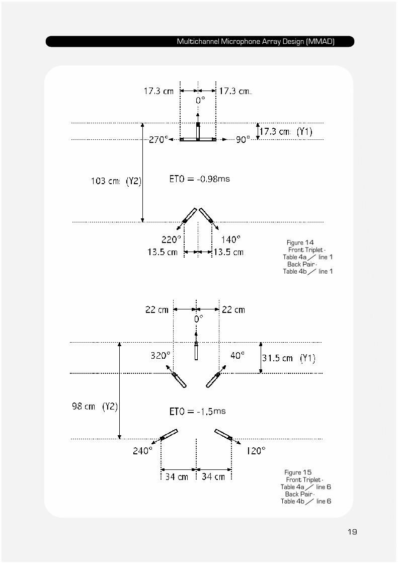
ms
Figure 14 Front Triplet -
Table 4a / line 1 Back Pair -
Table 4b / line 1
ms
Figure 15 Front Triplet -
Table 4a / line 6 Back Pair -
Table 4b / line 6
19
Multichannel Microphone Array Design (MMAD)
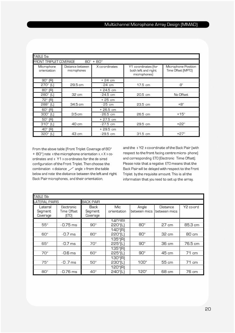
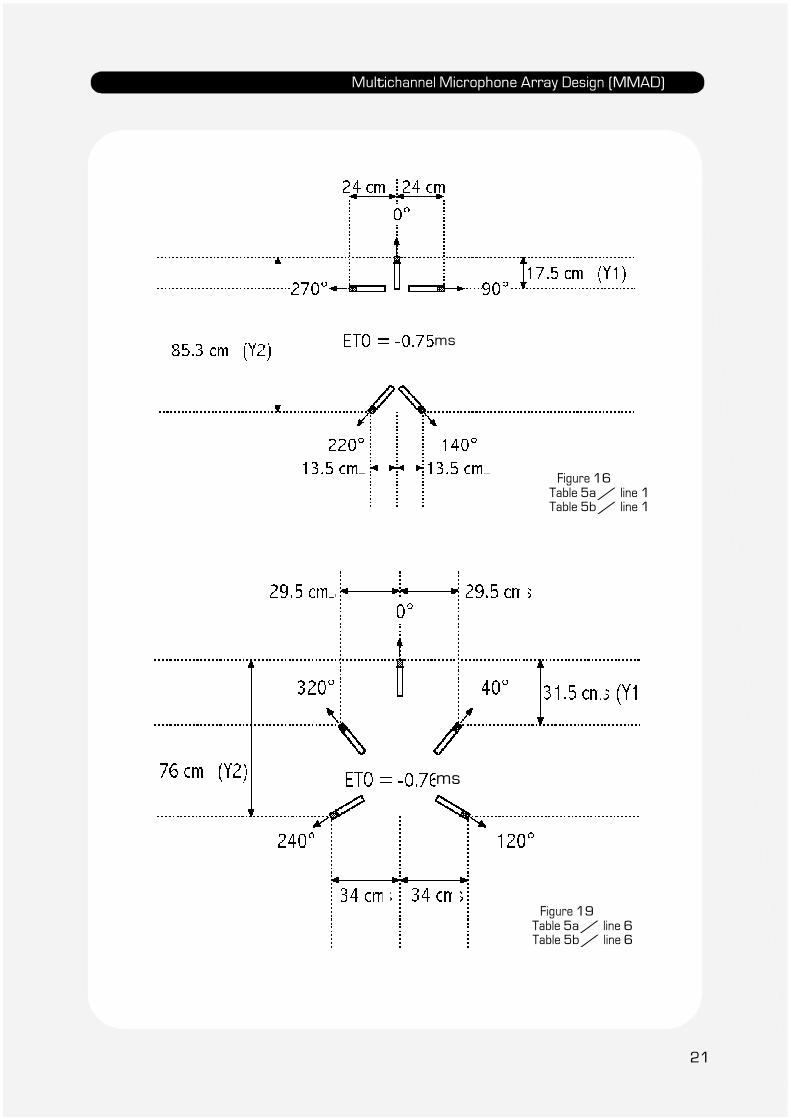
TABLE 5a FRONT TRIPLET COVERAGE 80° + 80°
Microphone
orientation Distance between microphones
X co-ordinates Y1 co-ordinates (for
both left and right microphones)
Microphone Position Time Offset (MPTO)
90° (R) + 24 cm 270° (L) 29.5 cm - 24 cm 17.5 cm -9° 80° (R) + 24.5 cm 280° (L) 32 cm - 24.5 cm 20.5 cm No Offset 72° (R) + 25 cm 288° (L) 34.5 cm - 25 cm 23.5 cm +8° 60° (R) + 26.5 cm 300° (L) 3.5 cm - 26.5 cm 26.5 cm +15° 50° (R) + 27.5 cm 310° (L) 40 cm - 27.5 cm 29.5 cm +22° 40° (R) + 29.5 cm 320° (L) 43 cm - 29.5 cm 31.5 cm +27°
From the above table (Front Triplet Coverage of 80°
+ 80°) note « the microphone orientation », « X » co-
ordinates and « Y1 » co-ordinates for the de- sired
configuration of the Front Triplet. Then choose the
combination « distance / angle » from the table
below and note the distance between the left and right
Back Pair microphones, and their orientation,
and the « Y2 » co-ordinate of the Back Pair (with
respect to the front facing centre micro- phone)
and corresponding ETO (Electronic Time Offset).
Please note that a negative ETO means that the
Back Pair will be delayed with respect to the Front
Triplet by the requisite amount. This is all the
information that you need to set up the array.
TABLE 5b LATERAL PAIRS BACK PAIR
Lateral Segment
Coverage
Electronic Time Offset
(ETO)
Back Segment
Coverage
Mic orientation
Angle between mics
Distance between mics
Y2 co-ord
140°(R) 55° - 0.75 ms 90° 220°(L) 80° 27 cm 85.3 cm
140°(R) 60° - 0.7 ms 80° 220°(L) 80° 32 cm 80 cm
135°(R) 65° - 0.7 ms 70° 225°(L) 90° 36 cm 76.5 cm
135°(R) 70° - 0.6 ms 60° 225°(L) 90° 45 cm 71 cm
130°(R) 75° - 0 .7 ms 50° 230°(L) 100° 55 cm 71 cm
120°(R) 80° - 0.76 ms 40° 240°(L) 120° 68 cm 76 cm
20
Multichannel Microphone Array Design (MMAD)
ms
Figure 16 Table 5a / line 1 Table 5b / line 1
ms
Figure 19 Table 5a / line 6 Table 5b / line 6
21
Multichannel Microphone Array Design (MMAD)
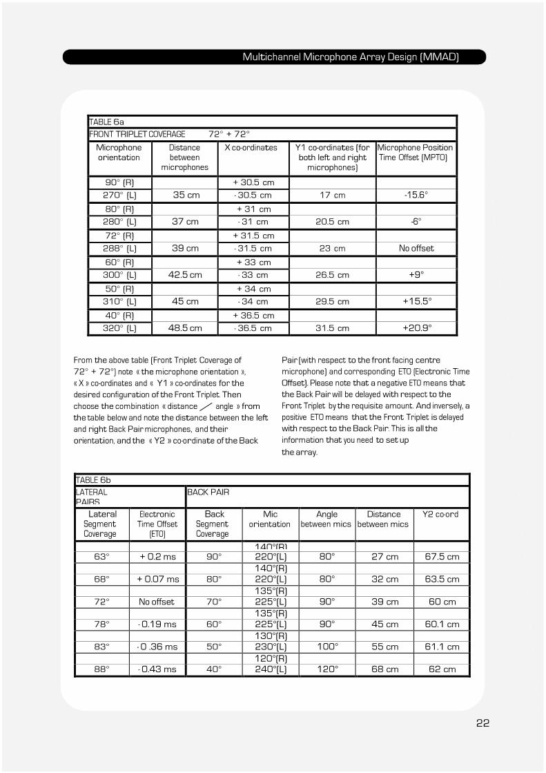
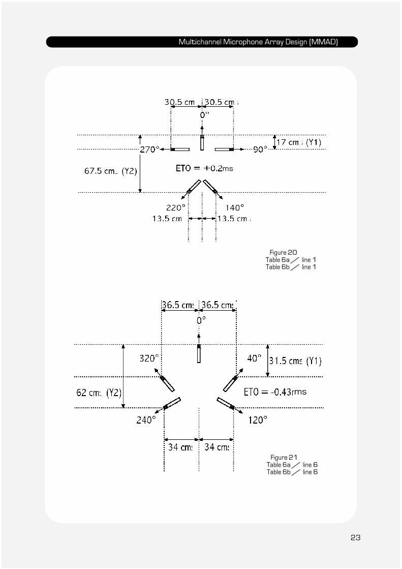
TABLE 6a
FRONT TRIPLET COVERAGE 72° + 72°
Microphone orientation
Distance between
microphones
X co-ordinates Y1 co-ordinates (for both left and right microphones)
Microphone Position Time Offset (MPTO)
90° (R) + 30.5 cm 270° (L) 35 cm - 30.5 cm 17 cm -15.6°
80° (R) + 31 cm 280° (L) 37 cm - 31 cm 20.5 cm -6°
72° (R) + 31.5 cm 288° (L) 39 cm - 31.5 cm 23 cm No offset
60° (R) + 33 cm 300° (L) 42.5 cm - 33 cm 26.5 cm +9°
50° (R) + 34 cm 310° (L) 45 cm - 34 cm 29.5 cm +15.5°
40° (R) + 36.5 cm 320° (L) 48.5 cm - 36.5 cm 31.5 cm +20.9°
From the above table (Front Triplet Coverage of
72° + 72°) note « the microphone orientation »,
« X » co-ordinates and « Y1 » co-ordinates for the
desired configuration of the Front Triplet. Then
choose the combination « distance / angle » from
the table below and note the distance between the left
and right Back Pair microphones, and their
orientation, and the « Y2 » co-ordinate of the Back
Pair (with respect to the front facing centre
microphone) and corresponding ETO (Electronic Time
Offset). Please note that a negative ETO means that
the Back Pair will be delayed with respect to the
Front Triplet by the requisite amount. And inversely, a
positive ETO means that the Front Triplet is delayed
with respect to the Back Pair. This is all the
information that you need to set up
the array.
TABLE 6b LATERAL
PAIRS BACK PAIR
Lateral Segment
Coverage
Electronic Time Offset
(ETO)
Back Segment
Coverage
Mic orientation
Angle between mics
Distance between mics
Y2 co-ord
140°(R) 63° + 0.2 ms 90° 220°(L) 80° 27 cm 67.5 cm
140°(R) 68° + 0.07 ms 80° 220°(L) 80° 32 cm 63.5 cm
135°(R) 72° No offset 70° 225°(L) 90° 39 cm 60 cm
135°(R) 78° - 0.19 ms 60° 225°(L) 90° 45 cm 60.1 cm
130°(R) 83° - 0 .36 ms 50° 230°(L) 100° 55 cm 61.1 cm
120°(R) 88° - 0.43 ms 40° 240°(L) 120° 68 cm 62 cm
22
Multichannel Microphone Array Design (MMAD)
ms
Figure 20 Table 6a / line 1 Table 6b / line 1
ms
Figure 21
Table 6a / line 6 Table 6b / line 6
23
Multichannel Microphone Array Design (MMAD)
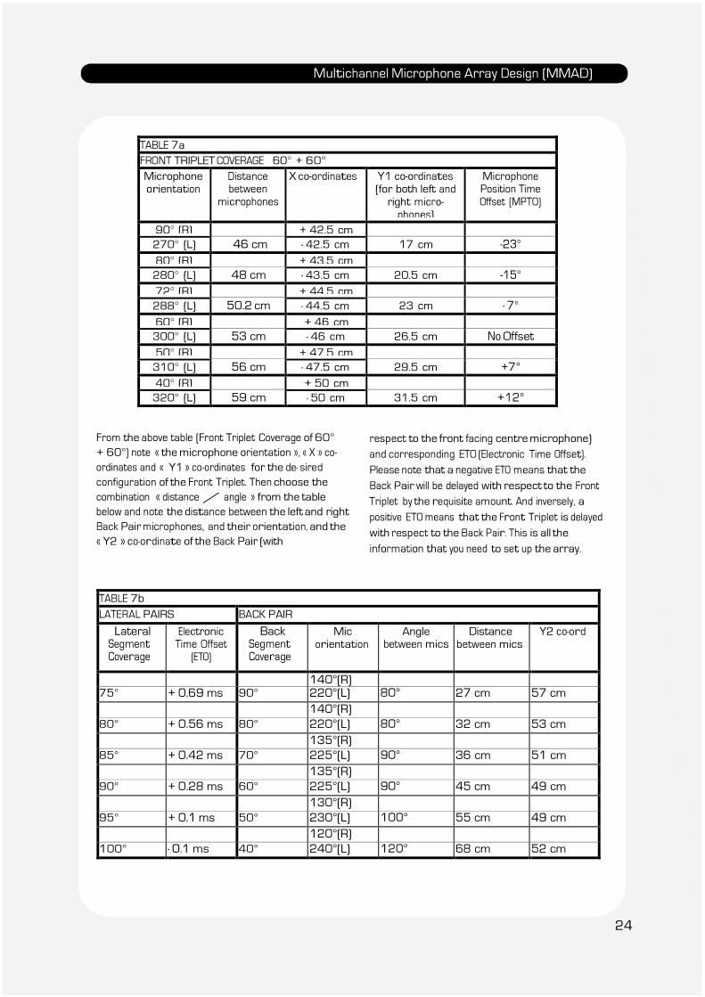
TABLE 7a FRONT TRIPLET COVERAGE 60° + 60° Microphone orientation
Distance between
microphones
X co-ordinates Y1 co-ordinates (for both left and
right micro- phones)
Microphone Position Time Offset (MPTO)
90° (R) + 42.5 cm 270° (L) 46 cm - 42.5 cm 17 cm -23°
80° (R) + 43.5 cm 280° (L) 48 cm - 43.5 cm 20.5 cm -15°
72° (R) + 44.5 cm 288° (L) 50.2 cm - 44.5 cm 23 cm - 7°
60° (R) + 46 cm 300° (L) 53 cm - 46 cm 26.5 cm No Offset
50° (R) + 47.5 cm 310° (L) 56 cm - 47.5 cm 29.5 cm +7°
40° (R) + 50 cm 320° (L) 59 cm - 50 cm 31.5 cm +12°
From the above table (Front Triplet Coverage of 60°
+ 60°) note « the microphone orientation », « X » co-
ordinates and « Y1 » co-ordinates for the de- sired
configuration of the Front Triplet. Then choose the
combination « distance / angle » from the table
below and note the distance between the left and right
Back Pair microphones, and their orientation, and the
« Y2 » co-ordinate of the Back Pair (with
respect to the front facing centre microphone)
and corresponding ETO (Electronic Time Offset).
Please note that a negative ETO means that the
Back Pair will be delayed with respect to the Front
Triplet by the requisite amount. And inversely, a
positive ETO means that the Front Triplet is delayed
with respect to the Back Pair. This is all the
information that you need to set up the array.
TABLE 7b
LATERAL PAIRS BACK PAIR
Lateral Segment
Coverage
Electronic Time Offset
(ETO)
Back Segment
Coverage
Mic orientation
Angle between mics
Distance between mics
Y2 co-ord
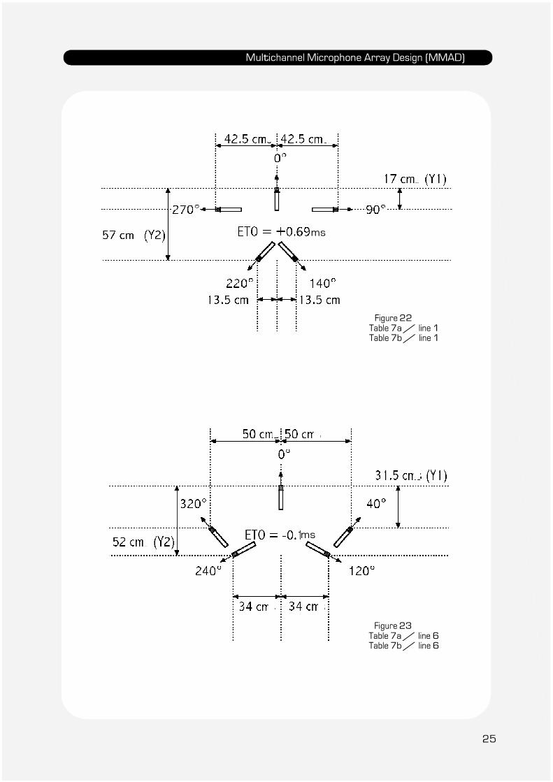
140°(R) 75° + 0.69 ms 90° 220°(L) 80° 27 cm 57 cm
140°(R) 80° + 0.56 ms 80° 220°(L) 80° 32 cm 53 cm
135°(R) 85° + 0.42 ms 70° 225°(L) 90° 36 cm 51 cm
135°(R) 90° + 0.28 ms 60° 225°(L) 90° 45 cm 49 cm
130°(R) 95° + 0.1 ms 50° 230°(L) 100° 55 cm 49 cm
120°(R) 100° - 0.1 ms 40° 240°(L) 120° 68 cm 52 cm
24
Multichannel Microphone Array Design (MMAD)
ms
Figure 22 Table 7a / line 1 Table 7b / line 1
ms
Figure 23
Table 7a / line 6 Table 7b / line 6
25
Multichannel Microphone Array Design (MMAD)
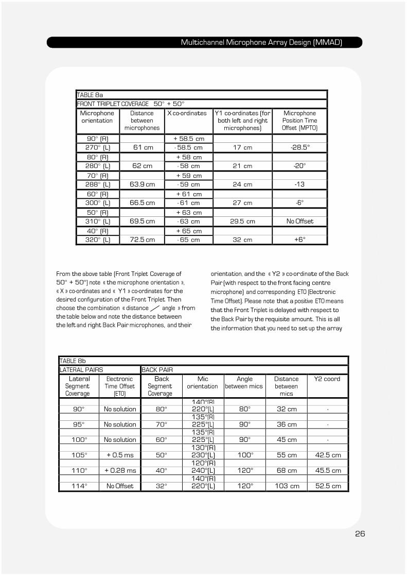
TABLE 8a FRONT TRIPLET COVERAGE 50° + 50°
Microphone orientation
Distance between
microphones
X co-ordinates Y1 co-ordinates (for both left and right
microphones)
Microphone Position Time Offset (MPTO)
90° (R) + 58.5 cm 270° (L) 61 cm - 58.5 cm 17 cm -28.5°
80° (R) + 58 cm 280° (L) 62 cm - 58 cm 21 cm -20°
70° (R) + 59 cm 288° (L) 63.9 cm - 59 cm 24 cm -13
60° (R) + 61 cm 300° (L) 66.5 cm - 61 cm 27 cm -6°
50° (R) + 63 cm 310° (L) 69.5 cm - 63 cm 29.5 cm No Offset
40° (R) + 65 cm 320° (L) 72.5 cm - 65 cm 32 cm +6°
From the above table (Front Triplet Coverage of
50° + 50°) note « the microphone orientation »,
« X » co-ordinates and « Y1 » co-ordinates for the
desired configuration of the Front Triplet. Then
choose the combination « distance / angle » from
the table below and note the distance between
the left and right Back Pair microphones, and their
orientation, and the « Y2 » co-ordinate of the Back
Pair (with respect to the front facing centre
microphone) and corresponding ETO (Electronic
Time Offset). Please note that a positive ETO means
that the Front Triplet is delayed with respect to
the Back Pair by the requisite amount.. This is all
the information that you need to set up the array
TABLE 8b LATERAL PAIRS BACK PAIR
Lateral Segment
Coverage
Electronic Time Offset
(ETO)
Back Segment
Coverage
Mic orientation
Angle between mics
Distance between
mics
Y2 coord
140°(R) 90° No solution 80° 220°(L) 80° 32 cm -
135°(R) 95° No solution 70° 225°(L) 90° 36 cm -
135°(R) 100° No solution 60° 225°(L) 90° 45 cm -
130°(R) 105° + 0.5 ms 50° 230°(L) 100° 55 cm 42.5 cm
120°(R) 110° + 0.28 ms 40° 240°(L) 120° 68 cm 45.5 cm
140°(R) 114° No Offset 32° 220°(L) 120° 103 cm 52.5 cm
26
Multichannel Microphone Array Design (MMAD)
ms
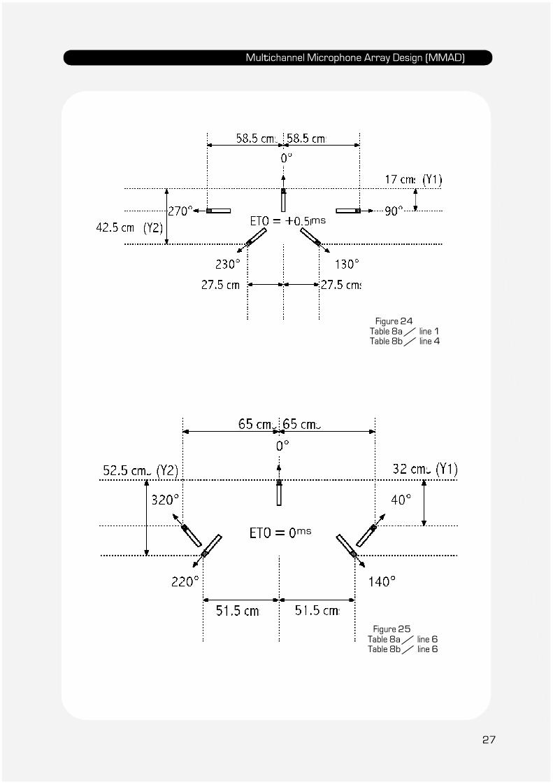
Figure 24 Table 8a / line 1 Table 8b / line 4
ms
Figure 25
Table 8a / line 6 Table 8b / line 6
27
Multichannel Microphone Array Design (MMAD)
References
1 1984 : 74th
AES Convention in Paris –
preprint 2072
« The Stereophonic Zoom, A Practical Approach to
determining the Characteristics of a Spaced Pair
of Microphones » by Michael Williams.
2 1987 : 82
nd
AES Convention in London –
preprint 2466
« Unified Theory of Microphone Systems for
Stereophonic Sound Recording »
by Michael Williams
3 1990 : 88
th
AES Convention in Montreux –
preprint 2931
« Operational Limits of the Variable M/S
Stereophonic Microphone System »
by Michael Williams
4 1991 : 91
st
AES Convention in New York –
preprint 3155
« Early Reflections and Reverberant Field
Distribution in Dual Microphone Stereophonic
Sound Recording Systems » by Michael Williams
5 1991 : 91
st
AES Convention in New York –
preprint 3157
« Microphone Arrays for Natural Multiphony »
by Michael Williams.
6 1992 : 92
nd
AES Convention in Vienna –
preprint 3252
« Frequency Dependent Hybrid Microphone Arrays
for Stereophonic Recording »
by Michael Williams.
7 « The Stereophonic Zoom » by Michael
Williams
8 1999 : 107th AES Convention in New York :
Preprint 4997
« Microphone Array Analysis for Multichannel
Sound Recording »
by Michael Williams and Guillaume Le Dû
9 2000 : 108th AES Convention in Paris :
Preprint 5157
« Multichannel Microphone Array Design » by
Michael Williams and Guillaume Le Dû
10 2000 : VDT in Hannover
« Loudspeaker Configuration and Channel Crosstalk
in Multichannel Microphone Array De- sign » by
Michael Williams and Guillaume Le Dû
11 2001 : 110th AES Convention in Amsterdam :
preprint 5336
« The Quick Reference Guide to Multichannel
Microphone Arrays Part 1: using Cardioid
Microphones » by Michael Williams and Guillaume Le Dû
12 2002 : 112th AES Convention in Munich :
preprint 5567
« Multichannel Microphone Array Design: Segment
Coverage Analysis above and below the Horizontal
Reference Plane » by Michael Williams
Michael Williams started his professional career at
the BBC Television Studios in London in 1960. In
1965 he moved to France to work for ''Societe Audax''
in Paris developing loudspeakers for professional
sound and television broadcasting, and later worked
for the ''Conservatoire National des Arts et Metiers''
in the adult education television service. In 1980 he
became a free-lance instructor in Audio Engineering
and Sound Recording Practice, working for most of
the major French national television and sound
broadcasting companies, as well as many training
schools and institutions. He is an active member of
the Audio Engineering Society, and has published many
papers on Stereo and Multichannel Recording
Systems over the past twenty years. He is at present
the AES Publications Sales Representative in Europe.
This version of MMAD
© 2010 Microphone Data Ltd
28
Related Documents