Multicast-service Distribution on a Cellular Network Assisted by Local Ad Hoc Networks Mariann Hauge*, Andreas Hafslund*, Frank Y. Li*, Øivind Kure** *UniK - University Graduate Center, P.O. Box 70, N-2027 Kjeller, Norway **Quantifiable Quality of Service in Communication Systems Norwegian University of Science and Technology, Trondheim, Norway {MariannH, AndreHa, FLi}@UniK.no, [email protected] Abstract—In this paper we propose an architecture for providing multicast services in 3G-cellular networks with the support from local ad hoc networks. The architecture is designed to increase the availability of high data-rate group services to wireless terminals. The architecture is based on a hybrid network which is composed of a central controlled cellular network and a number of local ad hoc networks. We present simulation results to show that this hybrid network architecture requires little cellular radio resources to provide multicast service to a majority of the mobile multicast subscribers. Two multicast routing protocols, one strongly centralized routing scheme and one distributed routing scheme, are proposed for this architecture. A detailed description of these protocols, and a rough protocol- overhead analysis are also given in the paper. I. INTRODUCTION 3 rd Generation (3G)-cellular networks should support high data-rate services as well as sporadic data traffic and traditional voice services. However, the limited bandwidth resources available in the radio network unfortunately implies that the 3G networks can support only a handful number of high data-rate users simultaneously. Hence, as wireless Internet access increases in popularity, the demand for high data-rate connections will soon exceed the available capacity. It is therefore important to find methods to improve the throughput in these networks. "Centre for Quantifiable Quality of Service in Communication Systems, Centre of Excellence" appointed by The Research Council of Norway, funded by the Research Council, NTNU and UNINETT. http://www.ntnu.no/Q2S/ There are several factors which motivated our work in this paper. Firstly, wide-area 3G-cellular networks operate in infrastructure mode and provide worldwide coverage from macro cells, with fairly low throughput. On the other hand, local-area wireless networks can operate in ad hoc mode and provide short coverage from pico cells, with relatively high data-rate. Secondly, although only the complex and expensive infrastructure of 3G-cellular networks can provide the desired anywhere always-on network connectivity, the peer-to-peer communication offered by the local area ad hoc networks is gaining its popularity due to the cost-effective IEEE 802.11b [1] enabled devices. Given these facts and potentials, it is natural to attempt to design a hybrid wireless network architecture that combines these two network types. In fact, many research groups have already noticed the tempting potential that lies in a hybrid wireless network architecture, and several designs have been proposed to solve different problems associated with cellular networks. A brief summary of these efforts is given in the next section We have been studying the network capacity improvement available from multicast (point-to- multipoint) transmission in cellular systems for a while. Multicast is currently used on the Internet for streaming of Internet radio channels, conference presentations, and other multimedia applications. Multicast improves the network's bandwidth budget by transmitting a packet requested by several users, only once on each link. 68

Welcome message from author
This document is posted to help you gain knowledge. Please leave a comment to let me know what you think about it! Share it to your friends and learn new things together.
Transcript
Multicast-service Distribution on a Cellular Network Assisted by Local Ad Hoc Networks
Mariann Hauge*, Andreas Hafslund*, Frank Y. Li*, Øivind Kure**
*UniK - University Graduate Center, P.O. Box 70, N-2027 Kjeller, Norway **Quantifiable Quality of Service in Communication Systems
Norwegian University of Science and Technology, Trondheim, Norway {MariannH, AndreHa, FLi}@UniK.no, [email protected]
Abstract—In this paper we propose an architecture
for providing multicast services in 3G-cellular networks with the support from local ad hoc networks. The architecture is designed to increase the availability of high data-rate group services to wireless terminals. The architecture is based on a hybrid network which is composed of a central controlled cellular network and a number of local ad hoc networks. We present simulation results to show that this hybrid network architecture requires little cellular radio resources to provide multicast service to a majority of the mobile multicast subscribers.
Two multicast routing protocols, one strongly centralized routing scheme and one distributed routing scheme, are proposed for this architecture. A detailed description of these protocols, and a rough protocol-overhead analysis are also given in the paper.
I. INTRODUCTION 3rd Generation (3G)-cellular networks should
support high data-rate services as well as sporadic data traffic and traditional voice services. However, the limited bandwidth resources available in the radio network unfortunately implies that the 3G networks can support only a handful number of high data-rate users simultaneously. Hence, as wireless Internet access increases in popularity, the demand for high data-rate connections will soon exceed the available capacity. It is therefore important to find methods to
improve the throughput in these networks.
"Centre for Quantifiable Quality of Service in Communication Systems,
Centre of Excellence" appointed by The Research Council of Norway, funded by the Research Council, NTNU and UNINETT. http://www.ntnu.no/Q2S/
There are several factors which motivated our work in this paper. Firstly, wide-area 3G-cellular networks operate in infrastructure mode and provide worldwide coverage from macro cells, with fairly low throughput. On the other hand, local-area wireless networks can operate in ad hoc mode and provide short coverage from pico cells, with relatively high data-rate. Secondly, although only the complex and expensive infrastructure of 3G-cellular networks can provide the desired anywhere always-on network connectivity, the peer-to-peer communication offered by the local area ad hoc networks is gaining its popularity due to the cost-effective IEEE 802.11b [1] enabled devices.
Given these facts and potentials, it is natural to attempt to design a hybrid wireless network architecture that combines these two network types. In fact, many research groups have already noticed the tempting potential that lies in a hybrid wireless network architecture, and several designs have been proposed to solve different problems associated with cellular networks. A brief summary of these efforts is given in the next section
We have been studying the network capacity improvement available from multicast (point-to-multipoint) transmission in cellular systems for a while. Multicast is currently used on the Internet for streaming of Internet radio channels, conference presentations, and other multimedia applications. Multicast improves the network's bandwidth budget by transmitting a packet requested by several users, only once on each link.
68
Unfortunately, also a single high data-rate multicast channel that covers the complete 3G cell/sector requires a large portion of the total radio resources. Thus, we introduce a new network architecture denoted as Cellular Network Assisted by Local Ad Hoc Networks (CeNALAN). The main idea of our architecture is to transmit the multicast data over a shorter range with the cellular network, and let the local ad hoc networks forward the data further on to the remaining subscribing terminals. More specifically, we consider a scenario where Universal Mobile Telecommunication System (UMTS) Terrestrial Radio Access Network (UTRAN) [2] and IEEE 802.11b-based ad hoc networks co-exist and co-operate. All terminals in this hybrid network are assumed to support both radio interfaces.
The focus of this paper is twofold: First we study the performance of the CeNALAN network architecture in turns of ad hoc network connectivity and cellular coverage. The trade-off between the perceived quality of a multicast service and the corresponding required cellular radio resources is also investigated. Next, we propose two multicast routing alternatives for the hybrid architecture; especially we focus on how to utilize the UMTS channel for signaling traffic in the routing schemes. We have chosen to define two routing protocols, one centralized scheme where the 3G Base Station (BS) is actively participating in setting up and maintaining the multicast distribution tree, and one distributed scheme which is based on stand-alone ad hoc routing. Our intention is to examine these protocols in more detail in future work, and finally to identify the most suitable protocol for multicast distribution in the CeNALAN environment
In the next section we summarize related work. Section III gives an overview of the CeNALAN architecture, while we explore the benefits and drawbacks associated with this architecture in Section IV. Section V presents the two proposed routing schemes, and gives a rough overhead analysis of the two protocols. Finally, concluding remarks are given in Section VI.
II. RELATED WORK Over the past few years, several approaches for a
combined cellular and multihop network model have been proposed. Some of these focus on higher total
throughput, while others attempt to increase the range of high bandwidth channels; some make multihop route decision based on channel quality, while others focus on short range hops. To support the architecture, a few proposals require only one single radio technology, and the rest require two different radio interfaces, one for the cellular channel and the other for the multihop wireless path.
In [3], the authors propose an approach called ad-hoc GSM (AGSM), wherein mobile-stations participate in relaying to improve coverage and robustness against radio link failures. This approach uses received signal strength as the parameter in the decision process to switch from direct base-station communications to a multihop path. In opportunity driven multiple access (ODMA) [4], a scheme considered by 3GPP, the high data-rate coverage of the cell is increased at the boundaries by allowing mobile stations inside the original high data-rate coverage area to act as relays for mobile-stations outside. Another approach, Intelligent Relaying (IR) is proposed in [5]. In this architecture the authors attempt to increase the total network capacity by reducing interference. Direct source and destination mobile to mobile communication is allowed. Transmission power is reduced in the multihop scenario. In [6], the proposed model for multi-hop cellular networks uses multi-hop relays for the mobile-stations to reach the base-station while reducing the transmission power of the mobile stations and the base-station. This model is shown to improve throughput performance when sources and destinations co-exist in a single wireless cell. Digital Relaying [7] uses terminals with good link quality to the base station as relay agents for terminals that experience poor link quality to the base station. SOPRANO, described in [8], uses a virtual cell splitting technique. Base stations, as well as mobile terminals reduce their transmission range where the relay agent/router is inside the coverage of the base station. Furthermore, the recent UCAN (Unified Cellular and Ad-Hoc Network) [9] architecture introduces local ad hoc network operation in the cellular infrastructure to enhance cellular network throughput while maintaining fairness for the users.
In [10], the authors propose an integrated cellular and ad-hoc relay (iCAR) approach wherein special mobile relays are placed between cells to relay traffic
69
fcaa
[athim
owama
poamba
provided interesting ideas for the proposed multicast routing protocols.
III. THE CENALAN ARCHITECTURE We have chosen to design a hybrid network
architecture where ad hoc, multihop networks are established on demand when assistance from these is needed by the 3G-cellular network. Several local ad hoc forwarding networks may coexist and cover adjacent areas. Ad hoc networks are established when the cellular network initiates this process, and they are active as long as the cellular network decides. The ad hoc networks serve the purpose of assisting the cellular network and can only be used to forward data that arrive via the 3G base station. We also make the simplified assumption that the 802.11-based radio transmission, and the 3G-cellular radio transmission do not interfere.
Fig. 1 shows one example of a CeNALAN network scenario. In the depicted situation the 3G-cell get assistance from two local ad hoc networks. The cellular network inspects the radio resource situation in each sector and decides how much resources it can allow a multicast channel to use. This decision infers
1
6
7 (MGTW)
8
9 MZONE
MZONE
43 (RELAY)
2 (MGTW)
5
Fig. 1. The figure shows one possible combination ofcellular and ad hoc networks. MZONE represents therange of the Cellular multicast channel. MGTW is thegateway between the Cellular multicast channel and thead hoc multicast distribution. Terminal no. 3 represents apassive relay that is not subscribing to the multicast data.
rom an overloaded cell to a relatively under-loaded ell and therein achieve load balancing. Mobile-ssisted data forwarding (MADF) [11] uses a similar pproach to reduce delay. Finally, a different approach is shown in SFINX
12] where wired terminals with a wireless interface ssist the cellular base station in forwarding data from e fixed network. SFINX uses the cellular network to prove the coverage of a high bandwidth WLAN. All the architectures mentioned above are focused
n point-to-point traffic. Different from those studies, e propose the CeNALAN architecture in this paper,
iming at performance improvement for point-to-ultipoint multicast traffic based on the dual network
rchitecture. Even though there exists many multicast routing
rotocols for ad hoc networks (e.g., [13]-[16]), none f these fit our architecture. However, we have dopted many of the principles from the protocols entioned above in the design of our protocols. The
roadcast based ad hoc routing protocol [17] which is ided by a central control mechanism has also
the range of the cellular multicast channel. MZONE (see Fig. 1) represents the area covered by this channel. All multicast terminals that are located inside MZONE are potential gateways (MGTWs) between the 3G-cellular distribution and an ad hoc multihop forwarding network. The MGTWs receive the multicast data from the cellular multicast channel and forward the packets on multicast distribution trees in the ad hoc networks.
Terminals that want to join a multicast service must register with the 3G-cellular network. The cellular network executes a Resource validation algorithm to decide how the multicast data shall be distributed to the terminals. The algorithm returns one of the following choices:
• Unicast channels to each multicast terminal. • Increase MZONE to accommodate the terminal. • Connect to an existing ad hoc forwarding network. • Establish a new ad hoc forwarding network. • No resources available.
70
The cellular network continuously monitors the multicast terminals and dynamically changes the data distribution method based on e.g., cellular channel quality, location of terminals, the number of terminals, and the amount of available cellular radio resources. The design of the Resource validation algorithm is for future study.
In the next section we explore the possible benefits available from the hybrid network architecture and show how this architecture affects multicast-service availability. Additionally, we investigate the significant trade-off associated with the chosen design.
IV. NETWORK CONNECTIVITY STUDY OF THE CENALAN ARCHITECTURE
We implemented a simple static simulator in Java and created a simulation environment for a network with 100 hexagonal 3G-cells. The radius of each cell is 1500m and the cells are placed in a 10 x 10 grid. Each cell is divided in 3 sectors. We choose to use 100 terminals for each sector. The total number of terminals are uniformly distributed on the entire network. Multicast subscribers (50% of the available terminals) are distributed uniformly among the terminals. The network is static (i.e. terminal mobility is not studied in the simulations). The simulator builds local ad hoc networks in the 3G-cells based on the following parameters:
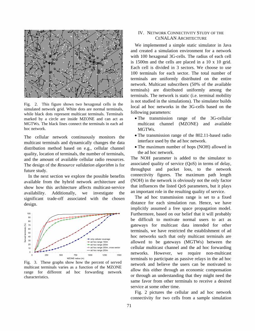
Fig. 2. This figure shows two hexagonal cells in the simulated network grid. White dots are normal terminals, while black dots represent multicast terminals. Terminals marked by a circle are inside MZONE and can act as MGTWs. The black lines connect the terminals in each ad hoc network.
• The transmission range of the 3G-cellular multicast channel (MZONE) and available MGTWs.
• The transmission range of the 802.11-based radio interface used by the ad hoc network.
• The maximum number of hops (NOH) allowed in the ad hoc network.
The NOH parameter is added to the simulator to associated quality of service (QoS) in terms of delay, throughput and packet loss, to the network connectivity figures. The maximum path length (NOH) in the network is obviously not the only factor that influences the listed QoS parameters, but it plays an important role in the resulting quality of service.
The ad hoc transmission range is set to a fixed distance for each simulation run. Hence, we have implicitly assumed a free space propagation model. Furthermore, based on our belief that it will probably be difficult to motivate normal users to act as gateways for multicast data intended for other terminals, we have restricted the establishment of ad hoc networks such that only multicast terminals are allowed to be gateways (MGTWs) between the cellular multicast channel and the ad hoc forwarding networks. However, we require non-multicast terminals to participate as passive relays in the ad hoc network and believe the users can be motivated to allow this either through an economic compensation or through an understanding that they might need the same favor from other terminals to receive a desired service at some other time.
0
10
20
30
40
50
60
70
80
90
100
0 250 500 750 1000 1250 1500MZONE radius (m)
Ser
ved
term
inal
s (%
)
only cellular coveragead hoc range 150mad hoc range 200mad hoc range 200m, cross sectorad hoc range 250m
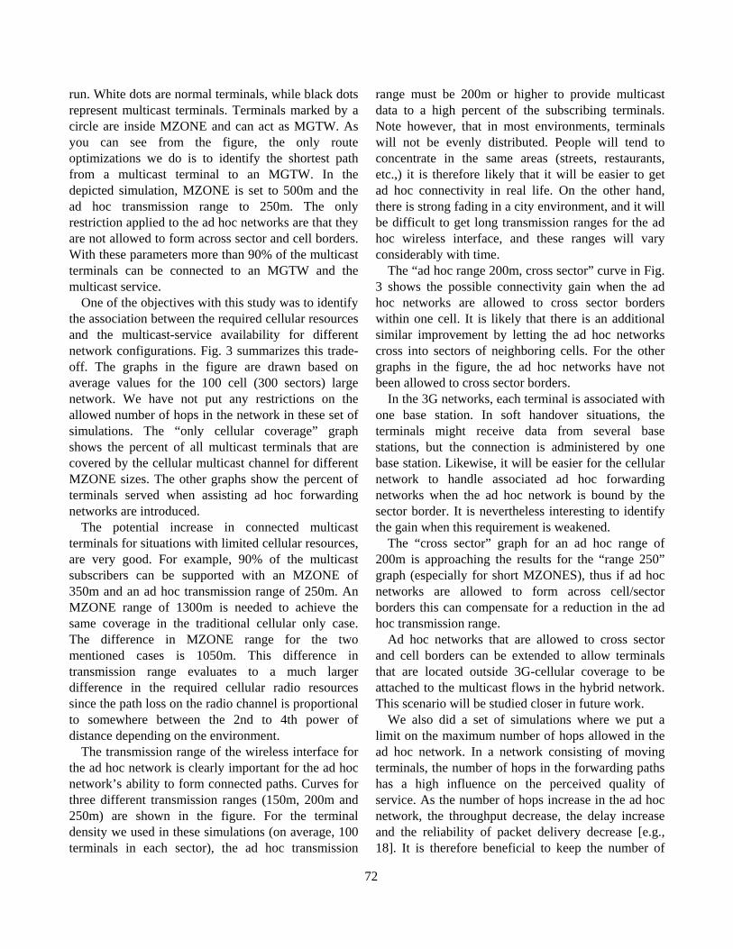
Fig. 3. These graphs show how the percent of served multicast terminals varies as a function of the MZONE range for different ad hoc forwarding network characteristics.
Fig. 2 pictures the cellular and ad hoc network connectivity for two cells from a sample simulation
71
run. White dots are normal terminals, while black dots represent multicast terminals. Terminals marked by a circle are inside MZONE and can act as MGTW. As you can see from the figure, the only route optimizations we do is to identify the shortest path from a multicast terminal to an MGTW. In the depicted simulation, MZONE is set to 500m and the ad hoc transmission range to 250m. The only restriction applied to the ad hoc networks are that they are not allowed to form across sector and cell borders. With these parameters more than 90% of the multicast terminals can be connected to an MGTW and the multicast service.
One of the objectives with this study was to identify the association between the required cellular resources and the multicast-service availability for different network configurations. Fig. 3 summarizes this trade-off. The graphs in the figure are drawn based on average values for the 100 cell (300 sectors) large network. We have not put any restrictions on the allowed number of hops in the network in these set of simulations. The “only cellular coverage” graph shows the percent of all multicast terminals that are covered by the cellular multicast channel for different MZONE sizes. The other graphs show the percent of terminals served when assisting ad hoc forwarding networks are introduced.
The potential increase in connected multicast terminals for situations with limited cellular resources, are very good. For example, 90% of the multicast subscribers can be supported with an MZONE of 350m and an ad hoc transmission range of 250m. An MZONE range of 1300m is needed to achieve the same coverage in the traditional cellular only case. The difference in MZONE range for the two mentioned cases is 1050m. This difference in transmission range evaluates to a much larger difference in the required cellular radio resources since the path loss on the radio channel is proportional to somewhere between the 2nd to 4th power of distance depending on the environment.
The transmission range of the wireless interface for the ad hoc network is clearly important for the ad hoc network’s ability to form connected paths. Curves for three different transmission ranges (150m, 200m and 250m) are shown in the figure. For the terminal density we used in these simulations (on average, 100 terminals in each sector), the ad hoc transmission
range must be 200m or higher to provide multicast data to a high percent of the subscribing terminals. Note however, that in most environments, terminals will not be evenly distributed. People will tend to concentrate in the same areas (streets, restaurants, etc.,) it is therefore likely that it will be easier to get ad hoc connectivity in real life. On the other hand, there is strong fading in a city environment, and it will be difficult to get long transmission ranges for the ad hoc wireless interface, and these ranges will vary considerably with time.
The “ad hoc range 200m, cross sector” curve in Fig. 3 shows the possible connectivity gain when the ad hoc networks are allowed to cross sector borders within one cell. It is likely that there is an additional similar improvement by letting the ad hoc networks cross into sectors of neighboring cells. For the other graphs in the figure, the ad hoc networks have not been allowed to cross sector borders.
In the 3G networks, each terminal is associated with one base station. In soft handover situations, the terminals might receive data from several base stations, but the connection is administered by one base station. Likewise, it will be easier for the cellular network to handle associated ad hoc forwarding networks when the ad hoc network is bound by the sector border. It is nevertheless interesting to identify the gain when this requirement is weakened.
The “cross sector” graph for an ad hoc range of 200m is approaching the results for the “range 250” graph (especially for short MZONES), thus if ad hoc networks are allowed to form across cell/sector borders this can compensate for a reduction in the ad hoc transmission range.
Ad hoc networks that are allowed to cross sector and cell borders can be extended to allow terminals that are located outside 3G-cellular coverage to be attached to the multicast flows in the hybrid network. This scenario will be studied closer in future work.
We also did a set of simulations where we put a limit on the maximum number of hops allowed in the ad hoc network. In a network consisting of moving terminals, the number of hops in the forwarding paths has a high influence on the perceived quality of service. As the number of hops increase in the ad hoc network, the throughput decrease, the delay increase and the reliability of packet delivery decrease [e.g., 18]. It is therefore beneficial to keep the number of
72
0
10
20
30
40
50
60
70
80
90
100
0 1 2 3 4 5 6 7 8 9 10 11 12 13 14 15Maximum number of hops
Ser
ved
term
inal
s (%
)
range 150m range 200m range 250m range 200m, cross sector
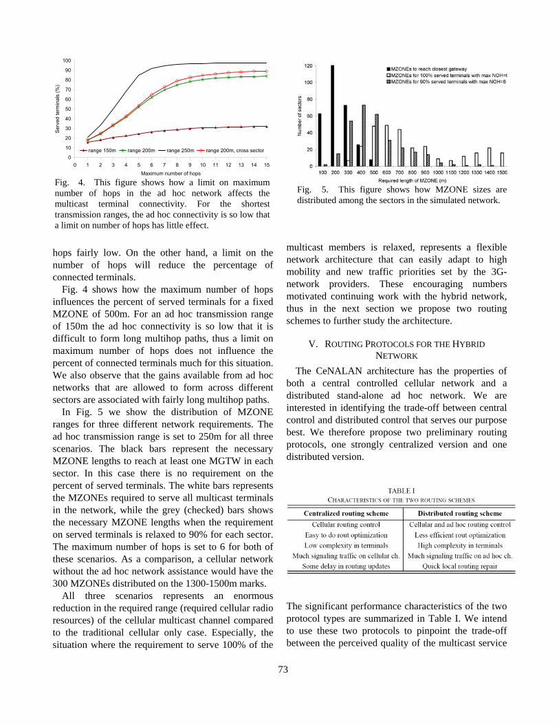
Fig. 4. This figure shows how a limit on maximum number of hops in the ad hoc network affects the multicast terminal connectivity. For the shortest transmission ranges, the ad hoc connectivity is so low that a limit on number of hops has little effect.
Fig. 5. This figure shows how MZONE sizes are distributed among the sectors in the simulated network.
hops fairly low. On the other hand, a limit on the number of hops will reduce the percentage of connected terminals.
Fig. 4 shows how the maximum number of hops influences the percent of served terminals for a fixed MZONE of 500m. For an ad hoc transmission range of 150m the ad hoc connectivity is so low that it is difficult to form long multihop paths, thus a limit on maximum number of hops does not influence the percent of connected terminals much for this situation. We also observe that the gains available from ad hoc networks that are allowed to form across different sectors are associated with fairly long multihop paths.
In Fig. 5 we show the distribution of MZONE ranges for three different network requirements. The ad hoc transmission range is set to 250m for all three scenarios. The black bars represent the necessary MZONE lengths to reach at least one MGTW in each sector. In this case there is no requirement on the percent of served terminals. The white bars represents the MZONEs required to serve all multicast terminals in the network, while the grey (checked) bars shows the necessary MZONE lengths when the requirement on served terminals is relaxed to 90% for each sector. The maximum number of hops is set to 6 for both of these scenarios. As a comparison, a cellular network without the ad hoc network assistance would have the 300 MZONEs distributed on the 1300-1500m marks.
All three scenarios represents an enormous reduction in the required range (required cellular radio resources) of the cellular multicast channel compared to the traditional cellular only case. Especially, the situation where the requirement to serve 100% of the
multicast members is relaxed, represents a flexible network architecture that can easily adapt to high mobility and new traffic priorities set by the 3G-network providers. These encouraging numbers motivated continuing work with the hybrid network, thus in the next section we propose two routing schemes to further study the architecture.
V. ROUTING PROTOCOLS FOR THE HYBRID NETWORK
The CeNALAN architecture has the properties of both a central controlled cellular network and a distributed stand-alone ad hoc network. We are interested in identifying the trade-off between central control and distributed control that serves our purpose best. We therefore propose two preliminary routing protocols, one strongly centralized version and one distributed version.
The significant performance characteristics of the two protocol types are summarized in Table I. We intend to use these two protocols to pinpoint the trade-off between the perceived quality of the multicast service
73
in the CeNALAN architecture and the utilization of the scarce radio resources in the cellular network.
Both schemes rely on the assumptions that terminals within cellular coverage maintain signaling connection to a cellular base station. The cellular radio network controller must have easy access to information about terminals located in neighboring cells/sectors, and the cellular network knows the approximate location of the terminals. The listed cellular requirements are all available in existing UMTS releases; however the information is not necessarily available at the network node required by the CeNALAN architecture. How to handle this is for future study.
Both routing protocols allow ad hoc networks to be formed across sector and cell borders. This makes it easier to form connected ad hoc multicast trees at the cost of more complexity in the 3G-cellular network.
We have chosen to avoid periodic “hello” messages in the protocol designs. These short, but numerous messages use disproportionately much resources in an 802.11-based technology whose overhead does not favor short messages. Instead the terminals maintain an accurate overview of active relay nodes in the vicinity by listening to the traffic on the wireless interface for the ad hoc network. A central controller (the cellular base station) is also available to oversee that the ad hoc connectivity information is adequate.
Both protocols rely on the assumption that the multicast data-flows have high packet intensity to keep accurate 1-hop neighbor information in the active terminals. Thus, during short pauses in the data traffic we require the 3G Base Station (BS) or the MGTW to forward dummy “heartbeat” packets on the ad hoc multicast trees. More details are presented in the appropriate places in the protocol descriptions.
Multicast group management is handled by the BS. The following procedure is identical for the two proposed routing protocols. Terminals that want to join a multicast flow must register with the cellular BS. Upon receiving a multicast join the BS runs the Resource validation algorithm to see how the multicast join can best be served. This algorithm returns the channel type to use for multicast distribution to this terminal. If the validation returns no resources available, then the join is refused. In all other cases the BS stores/updates the terminal’s multicast membership status and sends a message to
the terminal to inform how the multicast data will be distributed.
Similarly, a multicast terminal sends a reliable leave message to the BS when it wants to leave a multicast group. The BS updates the terminal’s multicast membership status and replies to the message. In situations where the terminal is not able to send leave (e.g., power down, no coverage, etc.) an automatic leave is generated by the 3G-cellular network when it detects that the terminal has disappeared.
Join and leave in cellular hand-over situations are also automatically handled by the cellular network. When an MGTW whishes to leave the multicast session, the BS will either attempt to establish a new ad hoc network to serve the affected multicast terminals, or attempt to have the affected terminals connect to existing forwarding trees in the neighborhood.
The following two sections describe the routing mechanism needed to support the multicast data distribution for the two proposed routing protocols. Each protocol is introduced with a brief summary of the protocol operation. More protocol-details are subsequently given in the following context. How to:
1) Establish an ad hoc multihop forwarding network.
2) Add members to an existing forwarding network. 3) Handle mobility in the forwarding network. 4) Handle link breaks in the forwarding network.
A. Centralized Multicast Routing Scheme In the centralized routing option, the cellular
network has total control over both cellular and ad hoc routing operations in the network. The characteristic features of this protocol are as follows: Each mobile terminal maintains a 1-hop neighbor table as long as it detects any activity on the ad hoc wireless interface. The table is updated based on overheard traffic on the ad hoc wireless channel. The table is forwarded (on the cellular signaling channel) periodically to the BS. The table can also be
74
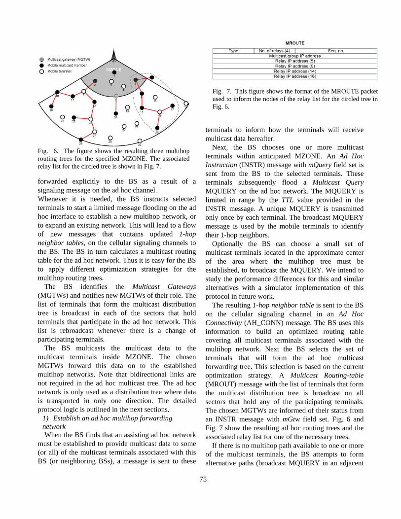
Fig. 7. This figure shows the format of the MROUTE packetused to inform the nodes of the relay list for the circled tree inFig. 6.
forwarded explicitly to the BS as a result of a signaling message on the ad hoc channel. Whenever it is needed, the BS instructs selected terminals to start a limited message flooding on the ad hoc interface to establish a new multihop network, or to expand an existing network. This will lead to a flow of new messages that contains updated 1-hop neighbor tables, on the cellular signaling channels to the BS. The BS in turn calculates a multicast routing table for the ad hoc network. Thus it is easy for the BS to apply different optimization strategies for the multihop routing trees.
The BS identifies the Multicast Gateways (MGTWs) and notifies new MGTWs of their role. The list of terminals that form the multicast distribution tree is broadcast in each of the sectors that hold terminals that participate in the ad hoc network. This list is rebroadcast whenever there is a change of participating terminals.
The BS multicasts the multicast data to the multicast terminals inside MZONE. The chosen MGTWs forward this data on to the established multihop networks. Note that bidirectional links are not required in the ad hoc multicast tree. The ad hoc network is only used as a distribution tree where data is transported in only one direction. The detailed protocol logic is outlined in the next sections.
1) Establish an ad hoc multihop forwarding network When the BS finds that an assisting ad hoc network
must be established to provide multicast data to some (or all) of the multicast terminals associated with this BS (or neighboring BSs), a message is sent to these
terminals to inform how the terminals will receive multicast data hereafter.
Next, the BS chooses one or more multicast terminals within anticipated MZONE. An Ad Hoc Instruction (INSTR) message with mQuery field set is sent from the BS to the selected terminals. These terminals subsequently flood a Multicast Query MQUERY on the ad hoc network. The MQUERY is limited in range by the TTL value provided in the INSTR message. A unique MQUERY is transmitted only once by each terminal. The broadcast MQUERY message is used by the mobile terminals to identify their 1-hop neighbors.
Optionally the BS can choose a small set of multicast terminals located in the approximate center of the area where the multihop tree must be established, to broadcast the MQUERY. We intend to study the performance differences for this and similar alternatives with a simulator implementation of this protocol in future work.
The resulting 1-hop neighbor table is sent to the BS on the cellular signaling channel in an Ad Hoc Connectivity (AH_CONN) message. The BS uses this information to build an optimized routing table covering all multicast terminals associated with the multihop network. Next the BS selects the set of terminals that will form the ad hoc multicast forwarding tree. This selection is based on the current optimization strategy. A Multicast Routing-table (MROUT) message with the list of terminals that form the multicast distribution tree is broadcast on all sectors that hold any of the participating terminals. The chosen MGTWs are informed of their status from an INSTR message with mGtw field set. Fig. 6 and Fig. 7 show the resulting ad hoc routing trees and the associated relay list for one of the necessary trees.
If there is no multihop path available to one or more of the multicast terminals, the BS attempts to form alternative paths (broadcast MQUERY in an adjacent
Fig. 6. The figure shows the resulting three multihop routing trees for the specified MZONE. The associated relay list for the circled tree is shown in Fig. 7.
75
area), or it chooses to terminate the service to the affected terminals.
2) Add members to an existing forwarding network When a terminal wants to join a multicast group and
it is aware of a relay node for the correct multicast session among its neighbors, it sends a join message with its current 1-hop neighbor table to the BS. Otherwise the terminal sends join and the BS replies with an INSTR message with the mQuery field set, to the new member to inform the terminal to start a limited flood of MQUERY messages on the ad hoc network. Affected terminals send their updated 1-hop neighbor tables to the BS, and the BS calculates a new forwarding tree that includes the new multicast terminal and broadcasts the updated list of relays.
If the terminal can not be connected to the existing ad hoc network, the BS attempts to establish an alternative connection, or informs the terminal that the service request is declined due to radio resource limitations.
3) Mobility in the forwarding network All terminals monitor the ad hoc wireless channel.
1-hop neighbor tables with updated neighbor information are sent periodically to the BS. Additionally, the neighbor table is sent to the BS a short delay after a terminal has received a new MQUERY signaling message.
The BS can command a terminal to broadcast an MQUERY when a new multicast terminal appears (see previous section), when a link break is detected (see next section), and also when an approaching terminal detects a multicast distribution tree and report a 1-hop neighbor table to the BS. This last option is included to give the BS the option to optimize the routing tree with new relays. Optionally, all mobile terminals could be set to send one-hop MQUERYs when they detect a forwarding network.
Associated with the maintenance of the 1-hop neighbor table and the routing table in the cellular BS is a clear trade-off between complexity in the mobile terminal and efficient use of UMTS channel resources. If the terminals keep a closer (smarter) watch on the transmissions on the ad hoc channel and thereby detect all useful changes in its environment, then a message with the current neighbor table can be sent to the BS when required, and there is no need for periodic reporting of this table. We intend to study the performance differences for this and similar
alternatives in future work. 4) Link break in the forwarding network Link break in the ad hoc network is discovered by
the terminal downlink of the break. The maximum delay from the link breaks until the separation is detected is inferred from frequency of the dummy “heartbeat” packets that are forwarded on the multicast tree during pauses in the data traffic.
When the affected terminal detects that the data-flow has stopped, it informs the BS of the break. The BS attempts to find a new path that avoids the broken link. If this is not possible it instructs (INSTR) the previous uplink and/or another on-tree terminal in the vicinity to do a limited flooding of the MQUERY message. This will in turn generate new AH_CONN messages with current 1-hop neighbor tables without the broken link, from which the BS can calculate a new route. If no new path is found, the BS decides how to progress (see Section 1).
B. Distributed Multicast Routing Scheme In the distributed routing option, the ad hoc
networks run a stand alone routing protocol that is aided by the cellular network. The characteristic features of this protocol are as follows: All multicast terminals inside MZONE are potential MGTWs. Each of these gateways attempt to build a downlink multicast routing tree by a request (flooded) and response (unicast) message sequence similar to the operation of MAODV[15]. Link breaks are handled by local repairs. Mobile terminals can also do a hand-off from one local ad hoc network to an adjacent ad hoc network if this network boosts a better connection to an MGTW.
This routing scheme requires bidirectional links. The 802.11 MAC layer provides reliable unicast. Some of the unicast messages in the protocol logic depend on this link-layer acknowledgment for the protocol to detect asymmetric links.
To enable for efficient link repair and hand off, we require that the Identification field of the IPv4 header is used as specified in the standard [19]. We use this field (possibly combined with the Fragment Offset for fragmented packets) to uniquely identify a multicast data packet. Additionally, each MGTW reset the TTL in the packet header to a known fixed TTL value for multicast data forwarding. The mobile terminals learn this fixed value from the BS’s join acknowledge. This
76
value and the current TTL value in a multicast data packet allow a terminal to calculate its distance (in number of hops) to the MGTW.
Each multicast terminal continuously monitors its distance (in number of hops) to the MGTW. If this number exceeds a set maximum, the BS is informed and it might choose to instruct a refresh of the multicast tree. The detailed protocol logic is outlined in the next sections.
1) Establish an ad hoc multihop forwarding network When the BS finds that an assisting ad hoc network
must be established to provide multicast data to some (or all) of the multicast terminals associated with this BS (or neighboring BSs), a message is sent to these terminals to inform how the terminals will receive multicast data hereafter.
Next, the BS multicast an INSTR message with the mQuery field set, to the multicast terminals inside MZONE. These terminals subsequently starts a limited flooding of the MQUERY message and wait for Multicast Reply (MREP) from the multicast terminals.
When a terminal receives a new, unique MQUERY it creates or updates an entry in its Multicast Routing Table. If the terminal is a multicast terminal it waits for a short period of time to allow for more MQUERYs to arrive where after it chooses the path
that best resembles the current optimization strategy and replies with an MREP (unicast) on this link.
Asymmetric links are detected when the terminal does not receive a link layer acknowledge of this message. If an asymmetric link is detected and the terminal does not have an alternative path to an MGTW, then the downlink terminal is notified. This terminal then searches it’s cache for an alternative path and so forth, until a path with bidirectional links to an MGTW is found, or no path exist.
Terminals receiving the MREP validate the corresponding routing entry and forward the message towards the MGTW. If the terminal is already a member of the tree, the table entry is updated and the message is discarded. The MGTW can start forwarding multicast traffic on the tree as soon as an MREP arrives at the gateway. A multicast terminal that was not able to connect to any of the newly established ad hoc multicast trees informs the BS of this problem. This terminal is then treated as a new arriving terminal (see next section).
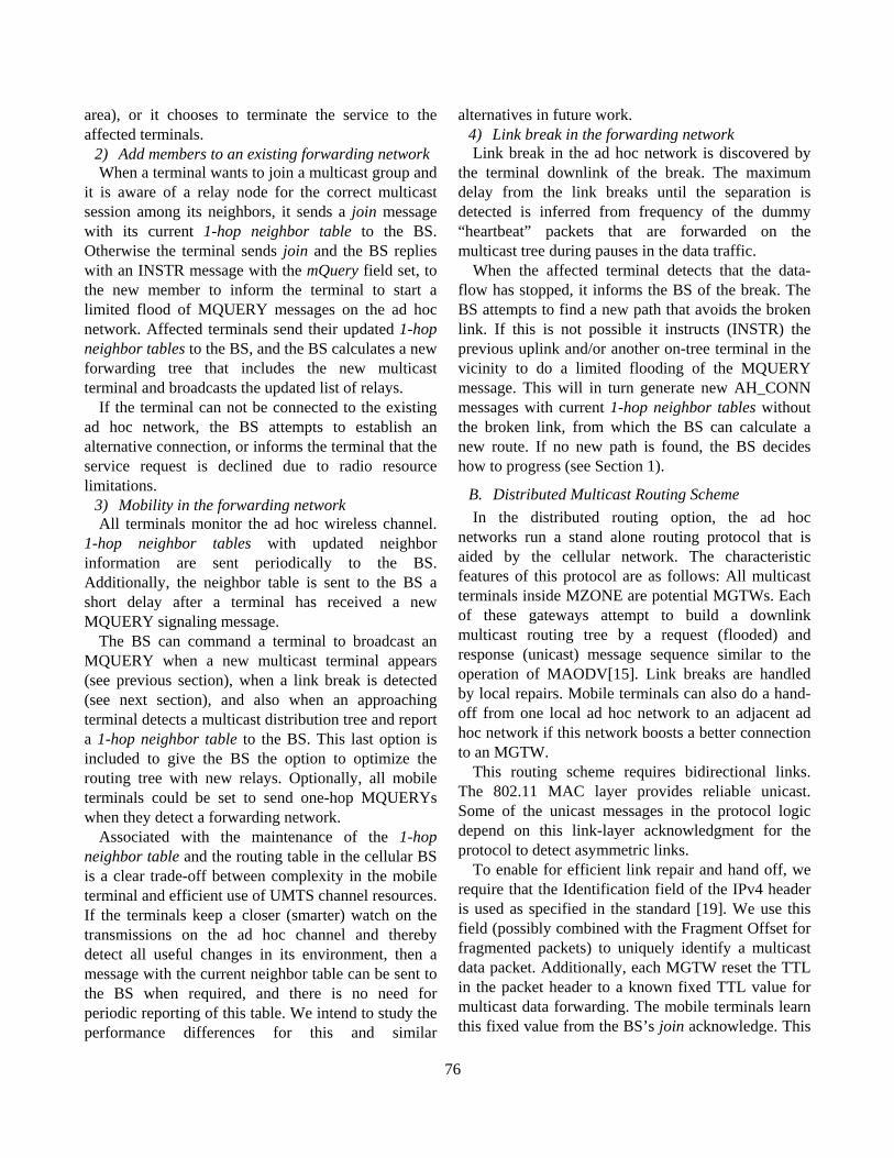
Fig. 8. The figure depicts a handover to an adjacent tree. Terminal no. 12 detects a better rout to an MGTW. 1) 12 sends an MREP (mcast_activate) to 8. 2) 8 includes 12 as downlink terminal. 3) 12 sends MTL to former up-link (Terminal no. 7) to inform that he has left the tree. 4) The links between terminals 7 and 12, and 7 and 2 are pruned from the tree.
2) Add members to an existing forwarding network When the BS receives a join from a terminal in the
vicinity of an existing ad hoc forwarding network, it sends an INSTR message with the mcast_connect field set, to the tentative multicast member.
If the terminal is aware of a forwarding tree for the required multicast session among its one-hop neighbors, then this terminal unicast an MREP with the mcast_activate flag set to the on-tree neighbor. Upon a successful unicast of the MREP, the new terminal is then attached to the multicast tree. A three-way message sequence is used to attach new members that are more than one hop away from the existing tree: connect - reply - activate. The newcomer performs an increasing range broadcast of the Multicast Connect (MCONN) message. This message is terminated by terminals participating on the routing tree. The on-tree terminals subsequently replies (unicast) with an MREP message.
When the new multicast terminal receive an MREP, it waits for a short period of time where after it chooses the best path and unicast an MREP with the mcast_activate flag to enable one of the available routes to the multicast tree. Hence, the new terminal is connected to the routing tree. If the terminal is unable to find a link to an existing tree, the BS is notified and attempts to establish alternative paths, or it chooses to
77
terminate the service to the affected terminal. 3) Mobility in the forwarding network All terminals continuously monitor the ad hoc
channel for neighbor data traffic. If a multicast terminal detects a parallel multicast flow, it will join the adjacent tree or branch if the new path offers a better route to an MGTW. Fig. 8 illustrates this situation.
The transferring terminal is attached to the new tree immediately after it successfully unicast an MREP with the mcast_activate flag set to the on-tree neighbor. The previous uplink node must be notified of this switch to know when to prune branches which are left with no multicast receivers. The multicast terminal will therefore unicast a Multicast-Tree Leave (MTL) to the previous uplink node. If this message for some reason can not be delivered, a soft-state mechanism will prune the leaving terminal from the old tree.
The soft state mechanism operates as follows: Each terminal participating in the ad hoc network use passive acknowledgment to verify if the downlink neighbor is still there. If the terminal has not heard the downlink node for a certain time, then the forward entry in the routing table times out and is deleted from the table. Consequently, the lost downlink node is pruned from the tree. This mechanism requires that the last node (leaf) in the tree sends an explicit acknowledge to the previous hop.
4) Link breaks in the forwarding network A broken link is detected when a terminal has not
received data for a defined period of time. As in the centralized routing option, the maximum delay from the break appears until it is detected, is inferred from the frequency of dummy “heartbeat” packets. If the affected terminal detects an adjacent flow of the multicast session, it joins this flow as described in the previous section. Otherwise, the link is attempted repaired with a connect - reply - activate sequence. The affected terminal broadcasts an MCONN message with the link_repair field set. This message also serves as a notification to downlink nodes that an uplink node is attempting to repair a broken link (i.e. downlink nodes should refrain from doing so) as well as a search for a new connection to the multicast distribution.
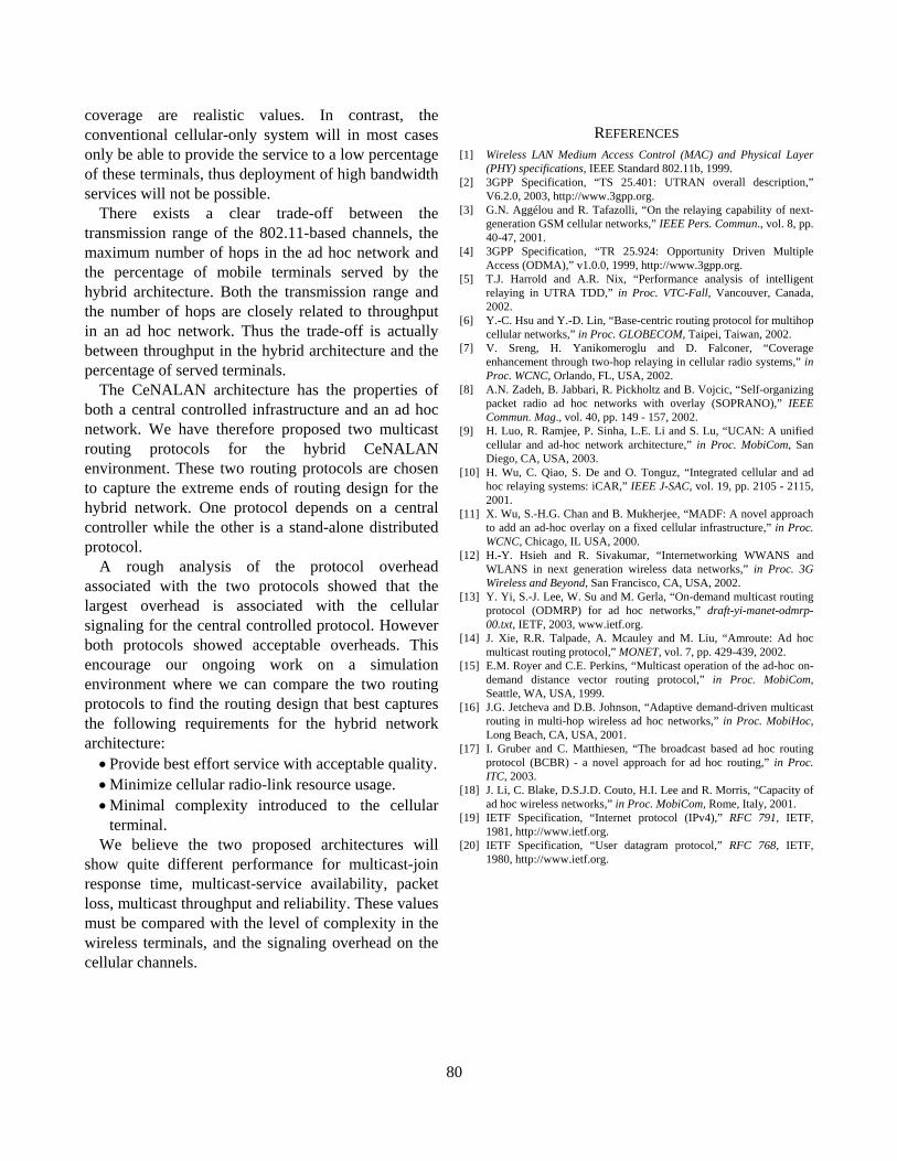
To avoid routing loops, only on-tree terminals that fill one of the following requirements can respond to the connection request.
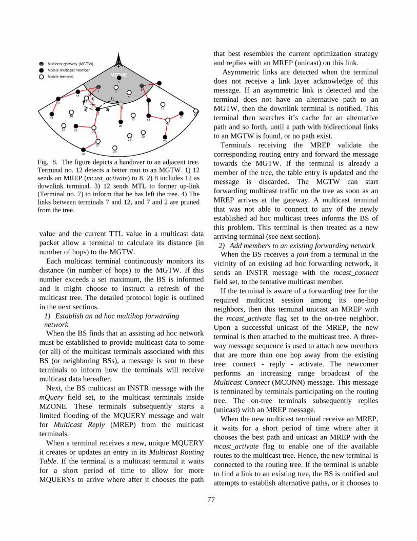
Fig. 9. This figure shows two of the message formats used in the routing protocols. The MQUERY message is used in the distributed routing protocol while the AH_CONN message is used in the centralized protocol.
• The terminal’s distance to an MGTW must be shorter or equal to the repairing terminal’s distance to the MGTW.
• The terminal has received a multicast packets with higher sequence number than the last packet received by the disconnected terminal.
When the terminal affected by the broken link receives an MREP from an active branch, the terminal waits for a short period of time to allow for other MREPs to arrive before it chooses the best path and activates this by unicasting an MREP with the mcast_activate flag set.
Optionally, terminals downlink of the first affected terminal could also attempt local repair to extend the search range. This is also a situation we will study closer with our simulation model in future work.
If a terminal is unable to find a new link to the tree, or the number of hops to the MGTW is above a certain threshold, the BS is notified.
5) Situations when the multicast trees are refreshed The distributed ad hoc routing scheme does not
include any periodic refresh of the multicast distribution tree. Maintenance of the routing tree depends on passive acknowledgment, detection of link break and local link repair. It is also possible to switch to another tree/branch connection if a better path is overheard.
After some time with many local link repairs, the distribution tree will be less optimal and it might be beneficial to refresh the tree structure. A new multicast routing tree is established when the
78
MGTWs initiates a new request (flooded) and response (unicast) message sequence. We envision that the BS should order the MGTWs to refresh the multicast trees for the following cases:
• The BS wants to add or remove an MGTW. • The BS wants to change the optimization strategy. • A terminal has reported a long distance to the
MGTW. In the next section we do a rough analytical
comparison of the protocol overhead in the two radio interfaces for the proposed multicast routing protocols.
C. Preliminary Protocol-Overhead Analysis Routing protocols for mobile networks tend to
require a significant part of the network bandwidth to maintain accurate routing information in the network. The overhead varies considerably among different protocols for varying terminal densities and varying traffic- and mobility-patterns. To get an indication of the protocol overhead associated with the two CeNALAN protocols, we calculated the approximate protocol overhead for some routing operations in the network scenario presented in Section IV.
Fig. 9 shows two of the message formats used in the routing protocols. We have added the size of the UDP [20] and IP [19] headers to all CeNALAN routing messages for the overhead calculation. For the ad hoc signaling messages we have also added the 802.11b MAC/PHY [1] header to the message sizes. This is done since a UMTS channel of for example 64kb/s already has MAC/PHY overhead included while an 802.11b channel of for example 1Mb/s refers to the raw data-rate on physical layer.
Our analysis is based on the scenario with 100 terminals in each sector, 50% multicast terminals, MZONE = 500m, and an ad hoc transmission range of 250m. This scenario gives the following average values: each terminal has 7 neighbors, there are 31 relays in each sector, 58 terminals are participation in
the multicast tree and we have 6 potential MGTWs. These average values are used to estimate the number of routing messages required in the signaling processes. For some messages these values are also used to estimate the size of the routing messages.
In addition to these parameters we have set the TTL for local routing messages to 3. Finally the total number of flooded messages is multiplied by 1.5 to compensate for a possible inefficiency in the flooding process. The inefficiency appear when the message with the shortest path to the sender is delayed and does not reach all terminals as the first message.
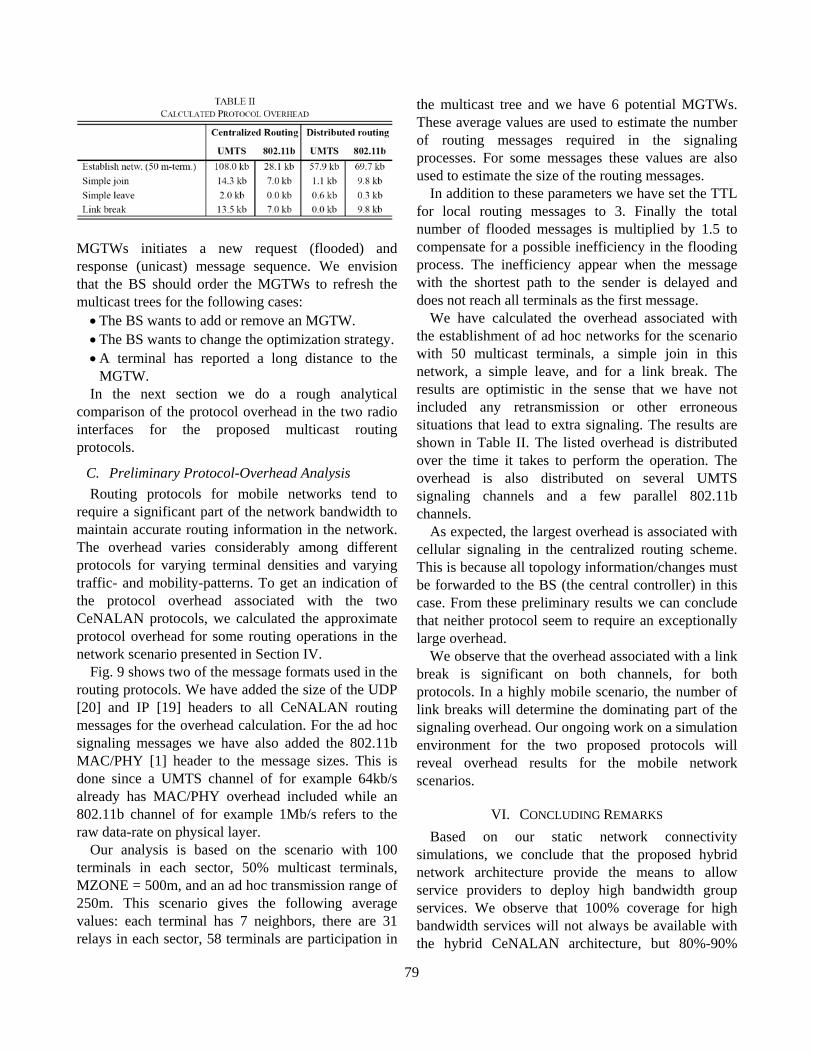
We have calculated the overhead associated with the establishment of ad hoc networks for the scenario with 50 multicast terminals, a simple join in this network, a simple leave, and for a link break. The results are optimistic in the sense that we have not included any retransmission or other erroneous situations that lead to extra signaling. The results are shown in Table II. The listed overhead is distributed over the time it takes to perform the operation. The overhead is also distributed on several UMTS signaling channels and a few parallel 802.11b channels.
As expected, the largest overhead is associated with cellular signaling in the centralized routing scheme. This is because all topology information/changes must be forwarded to the BS (the central controller) in this case. From these preliminary results we can conclude that neither protocol seem to require an exceptionally large overhead.
We observe that the overhead associated with a link break is significant on both channels, for both protocols. In a highly mobile scenario, the number of link breaks will determine the dominating part of the signaling overhead. Our ongoing work on a simulation environment for the two proposed protocols will reveal overhead results for the mobile network scenarios.
VI. CONCLUDING REMARKS Based on our static network connectivity
simulations, we conclude that the proposed hybrid network architecture provide the means to allow service providers to deploy high bandwidth group services. We observe that 100% coverage for high bandwidth services will not always be available with the hybrid CeNALAN architecture, but 80%-90%
79
coverage are realistic values. In contrast, the conventional cellular-only system will in most cases only be able to provide the service to a low percentage of these terminals, thus deployment of high bandwidth services will not be possible.
There exists a clear trade-off between the transmission range of the 802.11-based channels, the maximum number of hops in the ad hoc network and the percentage of mobile terminals served by the hybrid architecture. Both the transmission range and the number of hops are closely related to throughput in an ad hoc network. Thus the trade-off is actually between throughput in the hybrid architecture and the percentage of served terminals.
The CeNALAN architecture has the properties of both a central controlled infrastructure and an ad hoc network. We have therefore proposed two multicast routing protocols for the hybrid CeNALAN environment. These two routing protocols are chosen to capture the extreme ends of routing design for the hybrid network. One protocol depends on a central controller while the other is a stand-alone distributed protocol.
A rough analysis of the protocol overhead associated with the two protocols showed that the largest overhead is associated with the cellular signaling for the central controlled protocol. However both protocols showed acceptable overheads. This encourage our ongoing work on a simulation environment where we can compare the two routing protocols to find the routing design that best captures the following requirements for the hybrid network architecture:
• Provide best effort service with acceptable quality. • Minimize cellular radio-link resource usage. • Minimal complexity introduced to the cellular
terminal. We believe the two proposed architectures will
show quite different performance for multicast-join response time, multicast-service availability, packet loss, multicast throughput and reliability. These values must be compared with the level of complexity in the wireless terminals, and the signaling overhead on the cellular channels.
REFERENCES [1] Wireless LAN Medium Access Control (MAC) and Physical Layer
(PHY) specifications, IEEE Standard 802.11b, 1999. [2] 3GPP Specification, “TS 25.401: UTRAN overall description,”
V6.2.0, 2003, http://www.3gpp.org. [3] G.N. Aggélou and R. Tafazolli, “On the relaying capability of next-
generation GSM cellular networks,” IEEE Pers. Commun., vol. 8, pp. 40-47, 2001.
[4] 3GPP Specification, “TR 25.924: Opportunity Driven Multiple Access (ODMA),” v1.0.0, 1999, http://www.3gpp.org.
[5] T.J. Harrold and A.R. Nix, “Performance analysis of intelligent relaying in UTRA TDD,” in Proc. VTC-Fall, Vancouver, Canada, 2002.
[6] Y.-C. Hsu and Y.-D. Lin, “Base-centric routing protocol for multihop cellular networks,” in Proc. GLOBECOM, Taipei, Taiwan, 2002.
[7] V. Sreng, H. Yanikomeroglu and D. Falconer, “Coverage enhancement through two-hop relaying in cellular radio systems,” in Proc. WCNC, Orlando, FL, USA, 2002.
[8] A.N. Zadeh, B. Jabbari, R. Pickholtz and B. Vojcic, “Self-organizing packet radio ad hoc networks with overlay (SOPRANO),” IEEE Commun. Mag., vol. 40, pp. 149 - 157, 2002.
[9] H. Luo, R. Ramjee, P. Sinha, L.E. Li and S. Lu, “UCAN: A unified cellular and ad-hoc network architecture,” in Proc. MobiCom, San Diego, CA, USA, 2003.
[10] H. Wu, C. Qiao, S. De and O. Tonguz, “Integrated cellular and ad hoc relaying systems: iCAR,” IEEE J-SAC, vol. 19, pp. 2105 - 2115, 2001.
[11] X. Wu, S.-H.G. Chan and B. Mukherjee, “MADF: A novel approach to add an ad-hoc overlay on a fixed cellular infrastructure,” in Proc. WCNC, Chicago, IL USA, 2000.
[12] H.-Y. Hsieh and R. Sivakumar, “Internetworking WWANS and WLANS in next generation wireless data networks,” in Proc. 3G Wireless and Beyond, San Francisco, CA, USA, 2002.
[13] Y. Yi, S.-J. Lee, W. Su and M. Gerla, “On-demand multicast routing protocol (ODMRP) for ad hoc networks,” draft-yi-manet-odmrp-00.txt, IETF, 2003, www.ietf.org.
[14] J. Xie, R.R. Talpade, A. Mcauley and M. Liu, “Amroute: Ad hoc multicast routing protocol,” MONET, vol. 7, pp. 429-439, 2002.
[15] E.M. Royer and C.E. Perkins, “Multicast operation of the ad-hoc on-demand distance vector routing protocol,” in Proc. MobiCom, Seattle, WA, USA, 1999.
[16] J.G. Jetcheva and D.B. Johnson, “Adaptive demand-driven multicast routing in multi-hop wireless ad hoc networks,” in Proc. MobiHoc, Long Beach, CA, USA, 2001.
[17] I. Gruber and C. Matthiesen, “The broadcast based ad hoc routing protocol (BCBR) - a novel approach for ad hoc routing,” in Proc. ITC, 2003.
[18] J. Li, C. Blake, D.S.J.D. Couto, H.I. Lee and R. Morris, “Capacity of ad hoc wireless networks,” in Proc. MobiCom, Rome, Italy, 2001.
[19] IETF Specification, “Internet protocol (IPv4),” RFC 791, IETF, 1981, http://www.ietf.org.
[20] IETF Specification, “User datagram protocol,” RFC 768, IETF, 1980, http://www.ietf.org.
80
Related Documents