Multicast Configuration Guide for Cisco 8000 Series Routers, IOS XR Release 7.0.x First Published: 2020-03-15 Americas Headquarters Cisco Systems, Inc. 170 West Tasman Drive San Jose, CA 95134-1706 USA http://www.cisco.com Tel: 408 526-4000 800 553-NETS (6387) Fax: 408 527-0883

Welcome message from author
This document is posted to help you gain knowledge. Please leave a comment to let me know what you think about it! Share it to your friends and learn new things together.
Transcript

Multicast Configuration Guide for Cisco 8000 Series Routers, IOS XRRelease 7.0.xFirst Published: 2020-03-15
Americas HeadquartersCisco Systems, Inc.170 West Tasman DriveSan Jose, CA 95134-1706USAhttp://www.cisco.comTel: 408 526-4000
800 553-NETS (6387)Fax: 408 527-0883

THE SPECIFICATIONS AND INFORMATION REGARDING THE PRODUCTS IN THIS MANUAL ARE SUBJECT TO CHANGE WITHOUT NOTICE. ALL STATEMENTS,INFORMATION, AND RECOMMENDATIONS IN THIS MANUAL ARE BELIEVED TO BE ACCURATE BUT ARE PRESENTED WITHOUT WARRANTY OF ANY KIND,EXPRESS OR IMPLIED. USERS MUST TAKE FULL RESPONSIBILITY FOR THEIR APPLICATION OF ANY PRODUCTS.
THE SOFTWARE LICENSE AND LIMITED WARRANTY FOR THE ACCOMPANYING PRODUCT ARE SET FORTH IN THE INFORMATION PACKET THAT SHIPPED WITHTHE PRODUCT AND ARE INCORPORATED HEREIN BY THIS REFERENCE. IF YOU ARE UNABLE TO LOCATE THE SOFTWARE LICENSE OR LIMITED WARRANTY,CONTACT YOUR CISCO REPRESENTATIVE FOR A COPY.
The Cisco implementation of TCP header compression is an adaptation of a program developed by the University of California, Berkeley (UCB) as part of UCB's public domain version ofthe UNIX operating system. All rights reserved. Copyright © 1981, Regents of the University of California.
NOTWITHSTANDING ANY OTHERWARRANTY HEREIN, ALL DOCUMENT FILES AND SOFTWARE OF THESE SUPPLIERS ARE PROVIDED “AS IS" WITH ALL FAULTS.CISCO AND THE ABOVE-NAMED SUPPLIERS DISCLAIM ALL WARRANTIES, EXPRESSED OR IMPLIED, INCLUDING, WITHOUT LIMITATION, THOSE OFMERCHANTABILITY, FITNESS FOR A PARTICULAR PURPOSE AND NONINFRINGEMENT OR ARISING FROM A COURSE OF DEALING, USAGE, OR TRADE PRACTICE.
IN NO EVENT SHALL CISCO OR ITS SUPPLIERS BE LIABLE FOR ANY INDIRECT, SPECIAL, CONSEQUENTIAL, OR INCIDENTAL DAMAGES, INCLUDING, WITHOUTLIMITATION, LOST PROFITS OR LOSS OR DAMAGE TO DATA ARISING OUT OF THE USE OR INABILITY TO USE THIS MANUAL, EVEN IF CISCO OR ITS SUPPLIERSHAVE BEEN ADVISED OF THE POSSIBILITY OF SUCH DAMAGES.
Any Internet Protocol (IP) addresses and phone numbers used in this document are not intended to be actual addresses and phone numbers. Any examples, command display output, networktopology diagrams, and other figures included in the document are shown for illustrative purposes only. Any use of actual IP addresses or phone numbers in illustrative content is unintentionaland coincidental.
All printed copies and duplicate soft copies of this document are considered uncontrolled. See the current online version for the latest version.
Cisco has more than 200 offices worldwide. Addresses and phone numbers are listed on the Cisco website at www.cisco.com/go/offices.
Cisco and the Cisco logo are trademarks or registered trademarks of Cisco and/or its affiliates in the U.S. and other countries. To view a list of Cisco trademarks, go to this URL:https://www.cisco.com/c/en/us/about/legal/trademarks.html. Third-party trademarks mentioned are the property of their respective owners. The use of the word partner does not imply apartnership relationship between Cisco and any other company. (1721R)
© 2020 Cisco Systems, Inc. All rights reserved.

Preface
This guide describes the Cisco IOS XR Multicast configurations.
The preface contains the following sections:
• Changes to this Document, on page iii• Communications, Services, and Additional Information, on page iii
Changes to this DocumentThis table lists the changes made to this document since it was first printed.
Change SummaryDateRevision
Initial release of this document.March 2020Release 7.0.12
Communications, Services, and Additional Information• To receive timely, relevant information from Cisco, sign up at Cisco Profile Manager.
• To get the business impact you’re looking for with the technologies that matter, visit Cisco Services.
• To submit a service request, visit Cisco Support.
• To discover and browse secure, validated enterprise-class apps, products, solutions and services, visitCisco Marketplace.
• To obtain general networking, training, and certification titles, visit Cisco Press.
• To find warranty information for a specific product or product family, access Cisco Warranty Finder.
Cisco Bug Search Tool
Cisco Bug Search Tool (BST) is a web-based tool that acts as a gateway to the Cisco bug tracking systemthat maintains a comprehensive list of defects and vulnerabilities in Cisco products and software. BST providesyou with detailed defect information about your products and software.
Multicast Configuration Guide for Cisco 8000 Series Routers, IOS XR Release 7.0.xiii

Multicast Configuration Guide for Cisco 8000 Series Routers, IOS XR Release 7.0.xiv
PrefaceCommunications, Services, and Additional Information

C H A P T E R 1Implementing Layer-3 Multicast Routing
Want to deliver messages like corporate communications or newsletters to subscribed members using aminimum of network bandwidth?
With the traditional method like unicast, you can send messages from one source to one destination. Eachhost added to the network consumes bandwidth and it’s a challenge to reduce the load on the traffic.
On the other hand, broadcast sends messages to all the hosts in the network and not to the selected members.
Enable Multicast routing to deliver data traffic efficiently from a single source to multiple users or selectedmembers or even a group. It’s scalable and yet reduces the load on the traffic.
Learn about Multicast
Many applications such as video conferencing, corporate communications, distance learning, and distributionof software, stock quotes, and news involve multiple participants. Multicast is naturally suitable for thiscommunication paradigm.
Unlike unicast and broadcast, multicast allows a host to send a single data stream to a subset of hosts (grouptransmission) at about the same time. The IP hosts subscribed to a group are known as group members.
A multicast address is chosen from the multicast group. The sender uses that group address as the destinationaddress of a datagram to reach all members of the group
Packets delivered to group members are identified by a single multicast group address. Multicast packets aredelivered to a group using best-effort reliability, just like IP unicast packets.
Membership in a multicast group is dynamic; hosts can join and leave at any time. There's no restriction onthe location or number of members in a multicast group. A host can be a member of more than one multicastgroup at a time.
To send messages, multicast routing uses the following components:
• The sender or the source address
• The receiver or the multicast address
The receiver can be a group of members and are identified by a single multicast group address that fallsunder the IP Class D address range from 224.0.0.0 through 239.255.255.255. A multicast address ischosen for the receivers in a multicast group. Senders use that group address as the destination addressof a datagram to reach all members of the group.
Multicast Configuration Guide for Cisco 8000 Series Routers, IOS XR Release 7.0.x1

Any host, regardless of whether it's a member of a group or not, can send to agroup. However, only the members of a group receive the message
Note
• A protocol to identify the selected users to send a message.
Cisco IOS XR Software supports the following protocols to implement multicast routing:
• IGMP (IPv4): Use IGMP to allow hosts (IPv4) to communicate with routers to express the interest toreceive multicast traffic on specific groups. Use Multicast Listener Discovery (MLD v1/2) for IPv6.
• Protocol Independent Multicast in sparse mode (PIM-SM): Use PIM-SM between routers to track whichmulticast packets to forward to each other and to their directly connected LANs.
• Protocol IndependentMulticast in Source-SpecificMulticast (PIM-SSM): PIM-SSM is similar to PIM-SM.Hosts use PIM-SSM to report interest in receiving packets from specific source addresses.
PIM-SSM is made possible by IGMPv3 and MLDv2. Hosts can now indicate interest in specific sourcesusing IGMPv3 and MLDv2. SSM doesn't require a rendezvous point (RP) to operate.
This image shows IGMP and PIM-SM operating in a multicast environment.
Figure 1: Multicast Routing Protocols
• Key Protocols and Features Supported in the Cisco IOSXR SoftwareMulticast Routing Implementation,on page 3
• Prerequisites for Implementing Multicast Routing, on page 3• Restrictions for Implementing Multicast Routing, on page 4• Configuring Multicast, on page 4• Internet Group Management Protocol , on page 5• Protocol Independent Multicast, on page 7• Multicast only Fast Reroute, on page 22• Multicast Source Discovery Protocol, on page 23
Multicast Configuration Guide for Cisco 8000 Series Routers, IOS XR Release 7.0.x2
Implementing Layer-3 Multicast Routing

• Multicast Nonstop Forwarding, on page 24• Multicast Configuration Submodes, on page 24• Understanding Interface Configuration Inheritance, on page 25• Understanding Interface Configuration Inheritance Disablement, on page 26• Understanding Enabling and Disabling Interfaces, on page 26• Controlling Source Information on MSDP Peer Routers, on page 27• Multicast Routing Information Base, on page 28• Multicast Forwarding Information Base, on page 28• MSDP MD5 Password Authentication, on page 28• Label Switch Multicast, on page 29
Key Protocols and Features Supported in theCisco IOS XR Software Multicast Routing Implementation
Table 1: Supported Features for IPv4 and IPv6
IPv6 SupportIPv4 SupportFeature
NoYesAuto-RP
YesYesBGP
YesYesBSR
Yes (MLDv1/2)
Yes (IGMPv2/3)
Dynamic host registration
YesYes (IGMP v3)Explicit tracking of hosts, groups, and channels
NoYesMSDP
YesYesMulticast NSF
YesYesOOR handling
YesYesPIM-SM
YesYesPIM-SSM
YesYesPIM-SSM Mapping
Prerequisites for Implementing Multicast Routing• You must be in a user group associated with a task group that includes the proper task IDs. The commandreference guides include the task IDs required for each command. If you suspect user group assignmentis preventing you from using a command, contact your AAA administrator for assistance.
• You must be familiar with IPv4 and IPv6 multicast routing configuration tasks and concepts.
Multicast Configuration Guide for Cisco 8000 Series Routers, IOS XR Release 7.0.x3
Implementing Layer-3 Multicast RoutingKey Protocols and Features Supported in the Cisco IOS XR Software Multicast Routing Implementation

• Unicast routing must be operational.
• To enable multicast VPN, configure a VPN routing and forwarding (VRF) instance.
Restrictions for Implementing Multicast RoutingThe following features are not supported:
• Multicast VPN
• InterAS Option A
• PIM Bidir
• Multicast route statistics are not supported.
For troubleshooting purposes, you can configure accounting-per-prefix under rmulticast-routing modeto enable accounting for multicast routing for a limited number of routes temporarily.
You must disable accounting-per-prefix immediately after troubleshooting.
To filter which multicast routes are statistics enabled, see the hw-moduleroute-stats command under the chapterMulticast Routing Forwarding Commandsin Multicast Command Reference for Cisco 8000 Series Routers .
Note
• IPv6Multicast destination addresses are only allowed with a /96 mask. IPv6Multicast destination addressshould vary only in the last 32 bits of the group address. If they vary outside this range, they might mapto the same entry in the hardware.
Configuring MulticastTo configure multicast, perform the following configuration:
Router#configureRouter(config)# multicast-routingRouter(config-mcast)#address-family ipv4Router(config-mcast-default-ipv4)#interface all enableRouter(config-mcast-default-ipv4)#exitRouter(config-mcast)#router igmpRouter(config-igmp)#version 3Router(config-igmp)#commitTue Feb 4 04:43:37.679 UTCRouter(config-igmp)#exitRouter(config)#exit
Verification
Router#show pim ipv4 group-mapTue Feb 4 04:48:29.003 UTC
IP PIM Group Mapping Table
Multicast Configuration Guide for Cisco 8000 Series Routers, IOS XR Release 7.0.x4
Implementing Layer-3 Multicast RoutingRestrictions for Implementing Multicast Routing

(* indicates group mappings being used)(+ indicates BSR group mappings active in MRIB)
Group Range Proto Client Groups RP address Info
224.0.1.39/32* DM perm 0 0.0.0.0224.0.1.40/32* DM perm 0 0.0.0.0224.0.0.0/24* NO perm 0 0.0.0.0232.0.0.0/8* SSM config 0 0.0.0.0224.0.0.0/4* SM static 0 0.0.0.0 RPF: Null,0.0.0.0
To view the PIM topology table information for a specific group or all groups.Router#show pim topologyIP PIM Multicast Topology TableEntry state: (*/S,G)[RPT/SPT] Protocol Uptime InfoEntry flags: KAT - Keep Alive Timer, AA - Assume Alive, PA - Probe Alive
RA - Really Alive, IA - Inherit Alive, LH - Last HopDSS - Don't Signal Sources, RR - Register ReceivedSR - Sending Registers, SNR - Sending Null RegistersE - MSDP External, EX - ExtranetMFA - Mofrr Active, MFP - Mofrr Primary, MFB - Mofrr BackupDCC - Don't Check Connected, ME - MDT Encap, MD - MDT DecapMT - Crossed Data MDT threshold, MA - Data MDT AssignedSAJ - BGP Source Active Joined, SAR - BGP Source Active Received,SAS - BGP Source Active Sent, IM - Inband mLDP, X - VxLAN
Interface state: Name, Uptime, Fwd, InfoInterface flags: LI - Local Interest, LD - Local Dissinterest,
II - Internal Interest, ID - Internal Dissinterest,LH - Last Hop, AS - Assert, AB - Admin Boundary, EX - Extranet,BGP - BGP C-Multicast Join, BP - BGP Source Active Prune,MVS - MVPN Safi Learned, MV6S - MVPN IPv6 Safi Learned
(*,224.0.1.40) DM Up: 00:56:47 RP: 0.0.0.0JP: Null(never) RPF: Null,0.0.0.0 Flags: LH DSSLoopback0 00:56:47 off LI II LH
(21.5.7.2,232.1.1.1)SPT SSM Up: 00:00:44JP: Join(00:00:05) RPF: Null,0.0.0.0 Flags:FourHundredGigE0/0/0/11 00:00:44 fwd LI LH
Internet Group Management ProtocolCisco IOS XR Software provides support for Internet Group Management Protocol (IGMP) over IPv4.
IGMP provides a means for hosts to indicate which multicast traffic they are interested in and for routers tocontrol and limit the flow of multicast traffic throughout the network. Routers build state by means of IGMPand MLD messages; that is, router queries and host reports.
A set of queries and hosts that receive multicast data streams from the same source is called amulticast group.Hosts use IGMP and MLD messages to join and leave multicast groups.
IGMP messages use group addresses, which are Class D IP addresses. The high-order four bits of a Class Daddress are 1110. Host group addresses can be in the range 224.0.0.0 to 239.255.255.255. The address 224.0.0.0is guaranteed not to be assigned to any group. The address 224.0.0.1 is assigned to all systems on a subnet.The address 224.0.0.2 is assigned to all routers on a subnet.
Note
Multicast Configuration Guide for Cisco 8000 Series Routers, IOS XR Release 7.0.x5
Implementing Layer-3 Multicast RoutingInternet Group Management Protocol

IGMP VersionsThe following points describe IGMP versions 2, and 3:
• IGMP Version 2 extends IGMP allowing such features as the IGMP query timeout and the maximumquery-response time. See RFC 2236.
• IGMP Version 3 permits joins and leaves for certain source and group pairs instead of requesting trafficfrom all sources in the multicast group.
IGMP Routing ExampleThe below image illustrates two sources, 10.0.0.1 and 10.0.1.1, that are multicasting to group 239.1.1.1. Thereceiver wants to receive traffic addressed to group 239.1.1.1 from source 10.0.0.1 but not from source 10.0.1.1.The host must send an IGMPv3 message containing a list of sources and groups (S, G) that it wants to joinand a list of sources and groups (S, G) that it wants to leave. Router C can now use this information to prunetraffic from Source 10.0.1.1 so that only Source 10.0.0.1 traffic is being delivered to Router C.
Figure 2: IGMPv3 Signaling
When configuring IGMP, ensure that all systems on the subnet support the same IGMP version. The routerdoes not automatically detect Version 1 systems. Configure the router for Version 2 if your hosts do notsupport Version 3.
Note
Multicast Configuration Guide for Cisco 8000 Series Routers, IOS XR Release 7.0.x6
Implementing Layer-3 Multicast RoutingIGMP Versions
Configuring IGMP Per Interface States LimitThe IGMP Per Interface States Limit sets a limit on creating OLEs for the IGMP interface. When the set limitis reached, the group is not accounted against this interface but the group can exist in IGMP context for someother interface.
The following configuration sets a limit on the number of group memberships created on an interface as aresult of receiving IGMP or MLD membership reports.
router igmp | mld [vrf <vrfname>]interface <ifname>
(no) maximum groups-per-interface <max> [threshold <threshold>][<acl>]
!!
where,
<ifname> is the interface name
<max> is the maximum limit on the groups
<threshold> is the threshold number of groups at which point a syslog warning message will be issued
<acl> provides an option for selective accounting. If provided, only groups or (S,G)s that are permitted bythe ACL is accounted against the limit. Groups or (S, G)s that are denied by the ACL are not accounted againstthe limit. If not provided, all the groups are accounted against the limit.
The following messages are displayed when the threshold limit is reached for IGMP:
igmp[1160]: %ROUTING-IPV4_IGMP-4-OOR_THRESHOLD_REACHED : Threshold for Maximum number ofgroup per interface has been reached 3: Groups joining will soon be throttled.Config a higher max or take steps to reduce states
igmp[1160]: %ROUTING-IPV4_IGMP-4-OOR_LIMIT_REACHED : Maximum number of group per interfacehas been reached 6: Groups joining is throttled.Config a higher max or take steps to reduce states
Limitations
• If a user has configured a maximum of 20 groups and has reached the maximum number of groups, thenno more groups can be created. If the user reduces the maximum number of groups to 10, the 20 joinswill remain and a message of reaching the maximum is displayed. No more joins can be added until thenumber of groups has reached less than 10.
• If a user already has configured a maximum of 30 joins and add a max of 20, the configuration occursdisplaying a message that the maximum has been reached. No state change occurs and also no more joinscan occur until the threshold number of groups is brought down below the maximum number of groups.
Protocol Independent MulticastProtocol Independent Multicast (PIM) is a routing protocol designed to send and receive multicast routingupdates. Proper operation of multicast depends on knowing the unicast paths towards a source or an RP. PIM
Multicast Configuration Guide for Cisco 8000 Series Routers, IOS XR Release 7.0.x7
Implementing Layer-3 Multicast RoutingConfiguring IGMP Per Interface States Limit

relies on unicast routing protocols to derive this reverse-path forwarding (RPF) information. As the namePIM implies, it functions independently of the unicast protocols being used. PIM relies on the RoutingInformation Base (RIB) for RPF information.
If the multicast subsequent address family identifier (SAFI) is configured for Border Gateway Protocol (BGP),or if multicast intact is configured, a separate multicast unicast RIB is created and populated with the BGPmulticast SAFI routes, the intact information, and any IGP information in the unicast RIB. Otherwise, PIMgets information directly from the unicast SAFI RIB. Both multicast unicast and unicast databases are outsideof the scope of PIM.
The Cisco IOS XR implementation of PIM is based on RFC 4601 Protocol Independent Multicast - SparseMode (PIM-SM): Protocol Specification. For more information, see RFC 4601 and the Protocol IndependentMulticast (PIM): Motivation and Architecture Internet Engineering Task Force (IETF) Internet draft.
Cisco IOSXR Software supports PIM-SM, PIM-SSM, and PIMVersion 2 only. PIMVersion 1 hello messagesthat arrive from neighbors are rejected.
Note
PIM-Sparse ModeTypically, PIM in sparse mode (PIM-SM) operation is used in a multicast network when relatively few routersare involved in each multicast. Routers do not forward multicast packets for a group, unless there is an explicitrequest for traffic. Requests are accomplished using PIM join messages, which are sent hop by hop towardthe root node of the tree. The root node of a tree in PIM-SM is the rendezvous point (RP) in the case of ashared tree or the first-hop router that is directly connected to the multicast source in the case of a shortestpath tree (SPT). The RP keeps track of multicast groups, and the sources that send multicast packets areregistered with the RP by the first-hop router of the source.
As a PIM join travels up the tree, routers along the path set up the multicast forwarding state so that therequested multicast traffic is forwarded back down the tree. When multicast traffic is no longer needed, arouter sends a PIM prune message up the tree toward the root node to prune (or remove) the unnecessarytraffic. As this PIM prune travels hop by hop up the tree, each router updates its forwarding state appropriately.Ultimately, the forwarding state associated with a multicast group or source is removed. Additionally, if prunesare not explicitly sent, the PIM state will timeout and be removed in the absence of any further join messages.
PIM-SM is the best choice for multicast networks that have potential members at the end of WAN links.
PIM-Source Specific MulticastWhen PIM-SM is used with SSM, multi-cast routing is easier to manage. This is because RPs (rendezvouspoints) are not required and therefore, no shared trees (*,G) are built.
There is no specific IETF document defining PIM-SSM. However, RFC4607 defines the overall SSM behavior.
In the rest of this document, we use the term PIM-SSM to describe PIM behavior and configuration whenSSM is used.
PIM in Source-Specific Multicast operation uses information found on source addresses for a multicast groupprovided by receivers and performs source filtering on traffic.
• By default, PIM-SSM operates in the 232.0.0.0/8 multicast group range for IPv4. To configure thesevalues, use the ssm range command.
Multicast Configuration Guide for Cisco 8000 Series Routers, IOS XR Release 7.0.x8
Implementing Layer-3 Multicast RoutingPIM-Sparse Mode

• If SSM is deployed in a network already configured for PIM-SM, only the last-hop routers must beupgraded with Cisco IOS XR Software that supports the SSM feature.
• No MSDP SA messages within the SSM range are accepted, generated, or forwarded.
• SSM can be disabled using the ssm disable command.
• The ssm allow-override command allows SSM ranges to be overridden by more specific ranges.
In many multicast deployments where the source is known, protocol-independent multicast-source-specificmulticast (PIM-SSM)mapping is the obvious multicast routing protocol choice to use because of its simplicity.Typical multicast deployments that benefit from PIM-SSM consist of entertainment-type solutions like theETTH space, or financial deployments that completely rely on static forwarding.
In SSM, delivery of data grams is based on (S,G) channels. Traffic for one (S,G) channel consists of datagramswith an IP unicast source address S and the multicast group address G as the IP destination address. Systemsreceive traffic by becoming members of the (S,G) channel. Signaling is not required, but receivers mustsubscribe or unsubscribe to (S,G) channels to receive or not receive traffic from specific sources. Channelsubscription signaling uses IGMP to include mode membership reports, which are supported only in Version3 of IGMP (IGMPv3).
To run SSM with IGMPv3, SSM must be supported on the multicast router, the host where the application isrunning, and the application itself. Cisco IOS XR Software allows SSM configuration for an arbitrary subsetof the IP multicast address range 224.0.0.0 through 239.255.255.255.
When an SSM range is defined, existing IP multicast receiver applications do not receive any traffic whenthey try to use addresses in the SSM range, unless the application is modified to use explicit (S,G) channelsubscription.
Benefits of PIM-SSM over PIM-SM
PIM-SSM is derived from PIM-SM. However, whereas PIM-SM allows for the data transmission of all sourcessending to a particular group in response to PIM join messages, the SSM feature forwards traffic to receiversonly from those sources that the receivers have explicitly joined. Because PIM joins and prunes are sentdirectly towards the source sending traffic, an RP and shared trees are unnecessary and are disallowed. SSMis used to optimize bandwidth utilization and deny unwanted Internet broad cast traffic. The source is providedby interested receivers through IGMPv3 membership reports.
PIM-SM and PIM-SSMProtocol Independent Multicast (PIM) is a multicast routing protocol used to create multicast distributiontrees, which are used to forward multicast data packets. PIM is an efficient IP routing protocol that is“independent” of a routing table, unlike other multicast protocols such as Multicast Open Shortest Path First(MOSPF) or Distance Vector Multicast Routing Protocol (DVMRP).
Cisco IOS XR Software supports Protocol Independent Multicast in sparse mode (PIM-SM) and ProtocolIndependent Multicast in Source-Specific Multicast (PIM-SSM), permitting these modes to operate on yourrouter at the same time.
PIM-SM and PIM-SSM supports one-to-many applications by greatly simplifying the protocol mechanics fordeployment ease.
• PIM in sparse mode operation is used in a multicast network when relatively few routers are involvedin each multicast and these routers do not forward multicast packets for a group, unless there is an explicitrequest for the traffic.
Multicast Configuration Guide for Cisco 8000 Series Routers, IOS XR Release 7.0.x9
Implementing Layer-3 Multicast RoutingPIM-SM and PIM-SSM

• PIM in Source-Specific Multicast operation uses information found on source addresses for a multicastgroup provided by receivers and performs source filtering on traffic.
• By default, PIM-SSM operates in the 232.0.0.0/8 multicast group range for IPv4 and ff3x::/32(where x is any valid scope) in IPv6. To configure these values, use the ssm range command.
• If SSM is deployed in a network already configured for PIM-SM, only the last-hop routers must beupgraded with Cisco IOS XR Software that supports the SSM feature.
• No MSDP SA messages within the SSM range are accepted, generated, or forwarded.
Restrictions for PIM-SM and PIM-SSM
• Interoperability with SSM:
PIM-SM operations within the SSM range of addresses change to PIM-SSM. In this mode, only PIM(S,G) join and prune messages are generated by the router, and no (S,G) RP shared tree or (*,G) sharedtree messages are generated.
• IGMP Version:
To report multicast memberships to neighboring multicast routers, hosts use IGMP, and all routers onthe subnet must be configured with the same version of IGMP.
A router running Cisco IOS XR Software does not automatically detect Version 1 systems. You mustuse the version command in router IGMP configuration submode to configure the IGMP version.
Configuring PIM-SSM for Use in a Legacy Multicast DeploymentDeploying PIM-SSM in legacy multicast-enabled networks can be problematic, because it requires changesto the multicast group management protocols used on the various devices attached to the network. Host,routers, and switches must all be upgraded in such cases.
To support legacy hosts and switches in a PIM-SSM deployment, this router offers a configurable mappingfeature. Legacy group membership reports for groups in the SSM group range are mapped to a set of sourcesproviding service for that set of (S,G) channels.
Restrictions for PIM-SSM Mapping
PIM-SSM mapping does not modify the SSM group range. Instead, the legacy devices must report groupmembership for desired groups in the SSM group range.
Configuration Example
To creconfigure PIM-SSM for use in a legacy multicast deployment, you must complete the followingconfigurations:
1. Configuring a Set of Access Control Lists for Static SSM Mapping
2. Configuring a Set of Sources for SSM Mapping
Multicast Configuration Guide for Cisco 8000 Series Routers, IOS XR Release 7.0.x10
Implementing Layer-3 Multicast RoutingConfiguring PIM-SSM for Use in a Legacy Multicast Deployment

Configuration
To configure a set of access control lists (ACLs) where each ACL describes a set of SSM groups to be mappedto one or more sources:
Router#configureTue Feb 4 05:15:56.544 UTCRouter(config)#ipv4 access-list mc3Router(config-ipv4-acl)#permit 1 host 232.1.1.2 anyRouter(config-ipv4-acl)#commitTue Feb 4 05:16:28.752 UTCRouter(config-ipv4-acl)#exitRouter(config)#exitRouter:ios#
To configure a set of sources mapped by SSM groups:
Router#configureRouter(config)#router igmp vrf vrf20Router(config-igmp-vrf20)#ssm map static 232.1.1.1 mc2Router(config-igmp-vrf20)#exitRouter(config-igmp)#commit
Configuring PIM Per Interface States LimitThe PIM Per Interface States Limit sets a limit on creating OLEs for the PIM interface. When the set limit isreached, the group is not accounted against this interface but the group can exist in PIM context for someother interface.
The following configuration sets a limit on the number of routes for which the given interface may be anoutgoing interface as a result of receiving a PIM J/P message.
router pim | pim6 [vrf <vrfname>]interface <ifname>
maximum route-interfaces <max> [threshold <threshold>] [<acl>]!!
where,
<ifname> is the interface name
<max> is the maximum limit on the groups
<threshold> is the threshold number of groups at which point a syslog warning message will be issued
<acl> provides an option for selective accounting. If provided, only groups or (S,G)s that are permitted bythe ACL is accounted against the limit. Groups or (S, G)s that are denied by the ACL are not accounted againstthe limit. If not provided, all the groups are accounted against the limit.
The following messages are displayed when the threshold limit is reached for PIM:
pim[1157]: %ROUTING-IPV4_PIM-4-CAC_STATE_THRESHOLD : The interface GigabitEthernet0_2_0_0threshold number (4) allowed states has been reached.State creation will soon be throttled. Configure a higher state limit value or take stepsto reduce the number of states.
Multicast Configuration Guide for Cisco 8000 Series Routers, IOS XR Release 7.0.x11
Implementing Layer-3 Multicast RoutingConfiguring PIM Per Interface States Limit

pim[1157]: %ROUTING-IPV4_PIM-3-CAC_STATE_LIMIT : The interface GigabitEthernet0_2_0_0 maximumnumber (5) of allowed states has been reached.State creation will not be allowed from here on. Configure a higher maximum value or takesteps to reduce the number of states
Limitations
• If a user has configured a maximum of 20 groups and has reached the maximum number of groups, thenno more groups/OLEs can be created. If the user now decreases the maximum number to 10, the 20joins/OLEwill remain and a message of reaching the max is displayed. No more joins/OLE can be addedat this point until it has reached less than 10.
• If a user already has configured a maximum of 30 joins/OLEs and add a max of 20, the configurationoccurs displaying a message that the max has been reached. No states will change but no more joins/OLEscan happen until the number is brought down below the maximum number of groups.
• Local interest joins are added, even if the limit has reached and is accounted for it.
PIM Shared Tree and Source Tree (Shortest Path Tree)In PIM-SM, the rendezvous point (RP) is used to bridge sources sending data to a particular group withreceivers sending joins for that group. In the initial setup of state, interested receivers receive data from sendersto the group across a single data distribution tree rooted at the RP. This type of distribution tree is called ashared tree or rendezvous point tree (RPT) as illustrated in the below image. Data from senders is deliveredto the RP for distribution to group members joined to the shared tree.
Figure 3: Shared Tree and Source Tree (Shortest Path Tree)
Multicast Configuration Guide for Cisco 8000 Series Routers, IOS XR Release 7.0.x12
Implementing Layer-3 Multicast RoutingPIM Shared Tree and Source Tree (Shortest Path Tree)

Unless the spt-threshold infinity command is configured, this initial state gives way as soon as traffic isreceived on the leaf routers (designated router closest to the host receivers). When the leaf router receivestraffic from the RP on the RPT, the router initiates a switch to a data distribution tree rooted at the sourcesending traffic. This type of distribution tree is called a shortest path tree or source tree. By default, theCisco IOS XR Software switches to a source tree when it receives the first data packet from a source.
The following process describes the move from shared tree to source tree in more detail:
1. Receiver joins a group; leaf Router C sends a join message toward RP.
2. RP puts link to Router C in its outgoing interface list.
3. Source sends data; Router A encapsulates data in Register and sends it to RP.
4. RP forwards data down the shared tree to Router C and sends a join message toward Source. At this point,data may arrive twice at the RP, once encapsulated and once natively.
5. When data arrives natively (unencapsulated) at RP, RP sends a register-stop message to Router A.
6. By default, receipt of the first data packet prompts Router C to send a join message toward Source.
7. When Router C receives data on (S,G), it sends a prune message for Source up the shared tree.
8. RP deletes the link to Router C from outgoing interface of (S,G). RP triggers a prune message towardSource.
Join and prune messages are sent for sources and RPs. They are sent hop by hop and are processed by eachPIM router along the path to the source or RP. Register and register-stop messages are not sent hop by hop.They are exchanged using direct unicast communication between the designated router that is directly connectedto a source and the RP for the group.
The spt-threshold infinity command lets you configure the router so that it never switches to the shortestpath tree (SPT).
Tip
Multicast-IntactThemulticast-intact feature provides the ability to run multicast routing (PIM) when Interior Gateway Protocol(IGP) shortcuts are configured and active on the router. Both Open Shortest Path First, version 2 (OSPFv2),and Intermediate System-to-Intermediate System (IS-IS) support the multicast-intact feature. MultiprotocolLabel Switching Traffic Engineering (MPLS-TE) and IP multicast coexistence is supported in Cisco IOS XRSoftware by using the mpls traffic-eng multicast-intact IS-IS or OSPF router command. See the RoutingConfiguration Guide for Cisco 8000 Series Routers for information on configuring multicast intact using IS-ISand OSPF commands.
You can enable multicast-intact in the IGP when multicast routing protocols (PIM) are configured and IGPshortcuts are configured on the router. IGP shortcuts are MPLS tunnels that are exposed to IGP. The IGPsroute the IP traffic over these tunnels to destinations that are downstream from the egress router of the tunnel(from an SPF perspective). PIM cannot use IGP shortcuts for propagating PIM joins because reverse pathforwarding (RPF) cannot work across a unidirectional tunnel.
When you enable multicast-intact on an IGP, the IGP publishes a parallel or alternate set of equal-cost next-hopsfor use by PIM. These next-hops are called mcast-intact next-hops. The mcast-intact next-hops have thefollowing attributes:
Multicast Configuration Guide for Cisco 8000 Series Routers, IOS XR Release 7.0.x13
Implementing Layer-3 Multicast RoutingMulticast-Intact

• They are guaranteed not to contain any IGP shortcuts.
• They are not used for unicast routing but are used only by PIM to look up an IPv4 next hop to a PIMsource.
• They are not published to the Forwarding Information Base (FIB).
• When multicast-intact is enabled on an IGP, all IPv4 destinations that were learned through link-stateadvertisements are published with a set equal-cost mcast-intact next-hops to the RIB. This attributeapplies even when the native next-hops have no IGP shortcuts.
• In IS-IS, the max-paths limit is applied by counting both the native and mcast-intact next-hops together.(In OSPFv2, the behavior is slightly different.)
Designated RoutersCisco routers use PIM-SM to forward multicast traffic and follow an election process to select a designatedrouter (DR) when there is more than one router on a LAN segment.
The designated router is responsible for sending PIM register and PIM join and prune messages toward theRP to inform it about host group membership.
If there are multiple PIM-SM routers on a LAN, a designated router must be elected to avoid duplicatingmulticast traffic for connected hosts. The PIM router with the highest IP address becomes the DR for the LANunless you choose to force the DR election by use of the dr-priority command. The DR priority option allowsyou to specify the DR priority of each router on the LAN segment (default priority = 1) so that the router withthe highest priority is elected as the DR. If all routers on the LAN segment have the same priority, the highestIP address is again used as the tiebreaker.
DR election process is required only on multi access LANs. The last-hop router directly connected to the hostis the DR.
Note
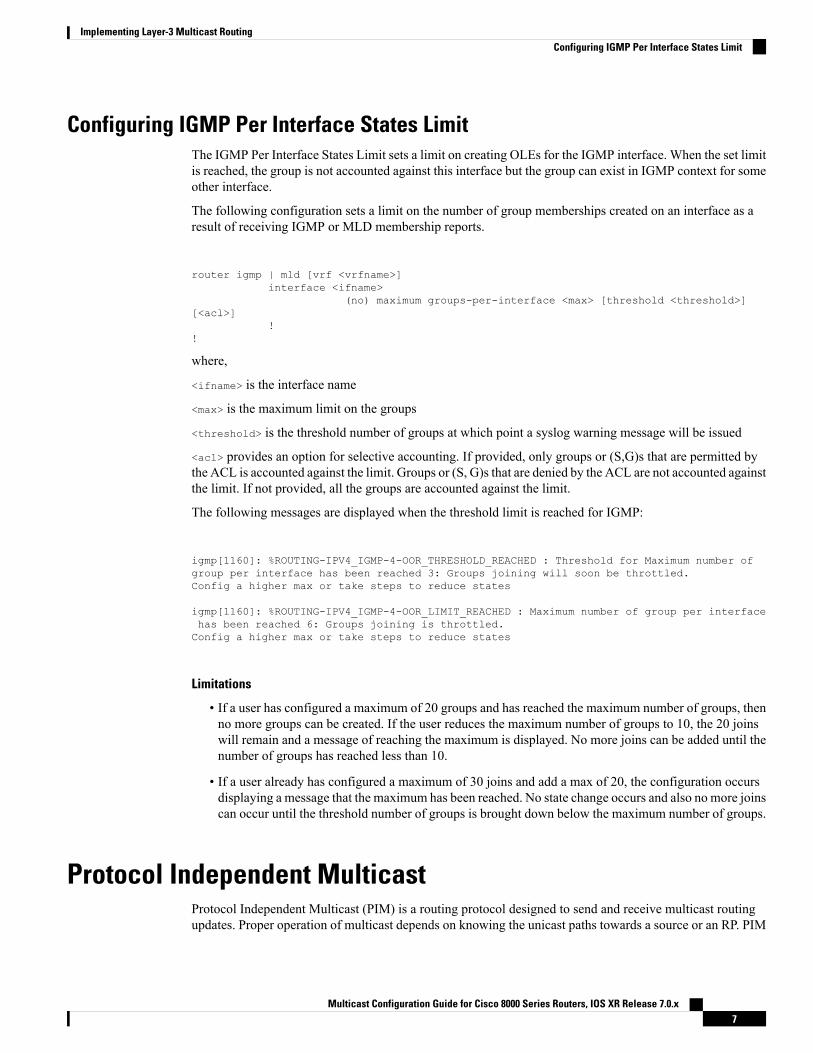
The figure "Designated Router Election on aMultiaccess Segment", below illustrates what happens on a multiaccess segment. Router A (10.0.0.253) and Router B (10.0.0.251) are connected to a common multi accessEthernet segment with Host A (10.0.0.1) as an active receiver for Group A. As the Explicit Join model is used,only Router A, operating as the DR, sends joins to the RP to construct the shared tree for Group A. If RouterB were also permitted to send (*,G) joins to the RP, parallel paths would be created and Host A would receiveduplicate multicast traffic. When Host A begins to source multicast traffic to the group, the DR's responsibilityis to send register messages to the RP. Again, if both routers were assigned the responsibility, the RP wouldreceive duplicate multicast packets.
Multicast Configuration Guide for Cisco 8000 Series Routers, IOS XR Release 7.0.x14
Implementing Layer-3 Multicast RoutingDesignated Routers
Figure 4: Designated Router Election on a Multiaccess Segment
If the DR fails, the PIM-SM provides a way to detect the failure of Router A and to elect a failover DR. If theDR (Router A) were to become inoperable, Router B would detect this situation when its neighbor adjacencywith Router A timed out. Because Router B has been hearing IGMP membership reports from Host A, italready has IGMP state for Group A on this interface and immediately sends a join to the RP when it becomesthe new DR. This step reestablishes traffic flow down a new branch of the shared tree using Router B.Additionally, if Host A were sourcing traffic, Router B would initiate a new register process immediatelyafter receiving the next multicast packet from Host A. This action would trigger the RP to join the SPT toHost A, using a new branch through Router B.
Two PIM routers are neighbors if there is a direct connection between them. To display your PIM neighbors,use the show pim neighbor command in EXEC mode.
Note
• They are not used for unicast routing but are used only by PIM to look up an IPv4 next hop to a PIMsource.
• They are not published to the Forwarding Information Base (FIB).
• When multicast-intact is enabled on an IGP, all IPv4 destinations that were learned through link-stateadvertisements are published with a set equal-cost mcast-intact next-hops to the RIB. This attributeapplies even when the native next-hops have no IGP shortcuts.
• In IS-IS, the max-paths limit is applied by counting both the native and mcast-intact next-hops together.(In OSPFv2, the behavior is slightly different.)
Configuration Example
Configures the router to use DR priority 4 for TenGigE interface 0/0/0/1, but other interfaces will inherit DRpriority 2:Router#configureRouter(config)#router pim
Multicast Configuration Guide for Cisco 8000 Series Routers, IOS XR Release 7.0.x15
Implementing Layer-3 Multicast RoutingDesignated Routers

Router(config-pim-default)#address-family ipv4Router(config-pim-default-ipv4)#dr-priority 2Router(config-pim-default-ipv4)#interface TenGigE0/0/0/1Router(config-pim-ipv4-if)#dr-priority 4Router(config-ipv4-acl)#commit
Running Configuration
Router#show run router pimrouter pimaddress-family ipv4dr-priority 2spt-threshold infinityinterface TenGigE 0/0/0/1dr-priority 4hello-interval 45
Verification
Verify if the parameters are set according to the configured values:Router#show pim interfacePIM interfaces in VRF defaultAddress Interface PIM Nbr Hello DR DR Count Intvl Prior100.1.1.1 TenGigE0/0/0/1 on 1 45 4 this system26.1.1.1 TenGigE0/0/0/26 on 1 30 2 this system
Rendezvous PointsWhen PIM is configured in sparse mode, you must choose one or more routers to operate as a rendezvouspoint (RP). A rendezvous point is a single common root placed at a chosen point of a shared distribution tree,as illustrated in PIM Shared Tree and Source Tree (Shortest Path Tree), on page 12. A rendezvous point canbe either configured statically in each box or learned through a dynamic mechanism.
PIM DRs forward data from directly connected multicast sources to the rendezvous point for distributiondown the shared tree. Data is forwarded to the rendezvous point in one of two ways:
• Encapsulated in register packets and unicast directly to the rendezvous point by the first-hop routeroperating as the DR.
• Multicast forwarded by the RPF forwarding algorithm, described in the Reverse-Path Forwarding, onpage 20, if the rendezvous point has itself joined the source tree.
The rendezvous point address is used by first-hop routers to send PIM register messages on behalf of a hostsending a packet to the group. The rendezvous point address is also used by last-hop routers to send PIM joinand prune messages to the rendezvous point to inform it about group membership. You must configure therendezvous point address on all routers (including the rendezvous point router).
A PIM router can be a rendezvous point for more than one group. Only one rendezvous point address can beused at a time within a PIM domain. The conditions specified by the access list determine for which groupsthe router is a rendezvous point.
You must manually configure a PIM router to function as a rendezvous point.
Configuration Example
The following example shows how to configure a static RP and allow backward compatibility:
Multicast Configuration Guide for Cisco 8000 Series Routers, IOS XR Release 7.0.x16
Implementing Layer-3 Multicast RoutingRendezvous Points

RP/0/RP0/CPU0:ios#configureThu Jan 30 08:30:02.187 UTCRP/0/RP0/CPU0:ios(config)#router pimRP/0/RP0/CPU0:ios(config-pim)#old-register-checksumRP/0/RP0/CPU0:ios(config-pim)#exitRP/0/RP0/CPU0:ios(config)#ipv4 access-list rp-accessRP/0/RP0/CPU0:ios(config-ipv4-acl)#permit 239.1.1.0 0.0.255.255RP/0/RP0/CPU0:ios(config-ipv4-acl)#commitThu Jan 30 08:31:22.679 UTCRP/0/RP0/CPU0:ios(config-ipv4-acl)#
Auto-RPAutomatic route processing (Auto-RP) is a feature that automates the distribution of group-to-RP mappingsin a PIM network. This feature has these benefits:
• It is easy to use multiple RPs within a network to serve different group ranges.
• It allows load splitting among different RPs.
• It facilitates the arrangement of RPs according to the location of group participants.
• It avoids inconsistent, manual RP configurations that might cause connectivity problems.
Multiple RPs can be used to serve different group ranges or to serve as hot backups for each other. To ensurethat Auto-RP functions, configure routers as candidate RPs so that they can announce their interest in operatingas an RP for certain group ranges. Additionally, a router must be designated as an RP-mapping agent thatreceives the RP-announcement messages from the candidate RPs, and arbitrates conflicts. The RP-mappingagent sends the consistent group-to-RP mappings to all remaining routers. Thus, all routers automaticallydetermine which RP to use for the groups they support.
By default, if a given group address is covered by group-to-RP mappings from both static RP configuration,and is discovered using Auto-RP or PIM BSR, the Auto-RP or PIM BSR range is preferred. To override thedefault, and use only the RP mapping, use the rp-address override keyword.
Tip
Auto-RP is not supported on VRF interfaces. Auto-RP Lite allows you to configure auto-RP on the CE router.It allows the PE router that has the VRF interface to relay auto-RP discovery, and announce messages acrossthe core and eventually to the remote CE. Auto-RP is supported in only the IPv4 address family.
Note
Configuring Example
Router#configureRouter(config)# router pimRouter(config-pim-ipv4)# auto-rp candidate-rp GigabitEthernet0/1/0/1 scope 31 group-list 2bidirRouter(config-pim-ipv4)# auto-rp mapping-agent GigabitEthernet0/1/0/1 scope 20Router(config-pim-ipv4)# exitRouter(config)# ipv4 access-list 2Router(config-ipv4-acl)# permit 239.1.1.1 0.0.0.0Router(config-ipv4-acl)#commit
Multicast Configuration Guide for Cisco 8000 Series Routers, IOS XR Release 7.0.x17
Implementing Layer-3 Multicast RoutingAuto-RP

This example shows that Auto-RPmessages are prevented from being sent out of the GigabitEthernet interface0/3/0/0. It also shows that access list 111 is used by the Auto-RP candidate and access list 222 is used by theboundary command to contain traffic on GigabitEthernet interface 0/3/0/0.ipv4 access-list 11110 permit 224.1.0.0 0.0.255.25520 permit 224.2.0.0 0.0.255.255!!Access list 111 is used by the Auto-RP candidate.!ipv4 access-list 22210 deny any host 224.0.1.3920 deny any host 224.0.1.40!!Access list 222 is used by the boundary command to contain traffic (onGigabitEthernet0/3/0/0) that is sent to groups 224.0.1.39 and 224.0.1.40.!router pimauto-rp mapping-agent loopback 2 scope 32 interval 30auto-rp candidate-rp loopback 2 scope 15 group-list 111 interval 30multicast-routinginterface hundredGigE 0/0/0/25boundary 222!
PIM Bootstrap RouterThe PIM bootstrap router (BSR) provides a fault-tolerant, automated RP discovery and distributionmechanism.
To avoid a single point of failure, you can configure several candidate BSRs in a PIM domain. A BSR iselected among the candidate BSRs automatically.
Candidates use bootstrap messages to discover which BSR has the highest priority. The candidate with thehighest priority sends an announcement to all PIM routers in the PIM domain that it is the BSR.
Routers that are configured as candidate RPs unicast to the BSR the group range for which they are responsible.The BSR includes this information in its bootstrap messages and disseminates it to all PIM routers in thedomain. Based on this information, all routers are able to map multicast groups to specific RPs. As long as arouter is receiving the bootstrap message, it has a current RP map.
Configuration Example
Configures the router as a candidate BSR with a hash mask length of 30:
Router# configureRouter:(config)# router pimRouter:(config-pim)# bsr candidate-bsr 10.0.0.1 hash-mask-len 30Router:(config-ipv4-acl)#commit
Configures the router to advertise itself as a candidate rendezvous point to the BSR in its PIM domain. Accesslist number 4 specifies the prefix associated with the candidate rendezvous point address 10.2.1.1 . Thisrendezvous point is responsible for the groups with the prefix 239.
RP/0/RP0/CPU0:ios#configureThu Jan 30 08:03:47.952 UTCRP/0/RP0/CPU0:ios(config)#router pimRP/0/RP0/CPU0:ios(config-pim)#bsr candidate-bsr 10.0.0.1 hash-mask-len 30RP/0/RP0/CPU0:ios(config-pim)#bsr candidate-rp 172.3.2.1 group-list 4 bidirRP/0/RP0/CPU0:ios(config-pim)#interface fourHundredGigE 0/0/0/1
Multicast Configuration Guide for Cisco 8000 Series Routers, IOS XR Release 7.0.x18
Implementing Layer-3 Multicast RoutingPIM Bootstrap Router

RP/0/RP0/CPU0:ios(config-pim-ipv4-if)# bsr-borderRP/0/RP0/CPU0:ios(config-pim-ipv4-if)#exitRP/0/RP0/CPU0:ios(config-pim-default-ipv4)#exitRP/0/RP0/CPU0:ios(config-pim)#exitRP/0/RP0/CPU0:ios(config)#ipv4 access-list 4RP/0/RP0/CPU0:ios(config-ipv4-acl)#permit 239.1.1.1 0.255.255.255RP/0/RP0/CPU0:ios(config-ipv4-acl)#commitThu Jan 30 08:05:36.780 UTCRP/0/RP0/CPU0:ios(config-ipv4-acl)#exitRP/0/RP0/CPU0:ios(config)#exit
Running Configuration
RP/0/RP0/CPU0:ios#show running-config router pimThu Jan 30 08:08:06.568 UTCrouter pimaddress-family ipv4interface FourHundredGigE0/0/0/1bsr-border!bsr candidate-bsr 10.0.0.1 hash-mask-len 30 priority 1bsr candidate-rp 172.3.2.1 group-list 4 priority 192 interval 60 bidir!!
Verification
Displays PIM candidate RP information for the BSR.RP/0/RP0/CPU0:ios#show pim bsr candidate-rpThu Jan 30 08:08:32.851 UTCPIM BSR Candidate RP Info
Cand-RP mode scope priority uptime group-list172.3.2.1 BD 16 192 00:00:00 4
Displays PIM candidate election information for the BSR.RP/0/RP0/CPU0:ios#show pim bsr electionThu Jan 30 08:08:58.846 UTCPIM BSR Election State
Cand/Elect-State Uptime BS-Timer BSR C-BSR
Inactive/Accept-Any 00:00:00 00:00:00 0.0.0.0 [0, 0] 10.0.0.1 [1, 30]
Displays PIM RP cache information for the BSR.
RP/0/RP0/CPU0:ios#show pim bsr rp-cacheThu Jan 30 08:09:44.901 UTCPIM BSR Candidate RP Cache
Displays group-to-PIM mode mapping.
RP/0/RP0/CPU0:ios#show pim ipv4 group-mapThu Jan 30 08:10:14.793 UTCNo ranges found.
Multicast Configuration Guide for Cisco 8000 Series Routers, IOS XR Release 7.0.x19
Implementing Layer-3 Multicast RoutingPIM Bootstrap Router

Reverse-Path ForwardingReverse-path forwarding (RPF) is an algorithm used for forwarding multicast datagrams. It functions asfollows:
• If a router receives a datagram on an interface it uses to send unicast packets to the source, the packethas arrived on the RPF interface.
• If the packet arrives on the RPF interface, a router forwards the packet out the interfaces present in theoutgoing interface list of a multicast routing table entry.
• If the packet does not arrive on the RPF interface, the packet is silently discarded to prevent loops.
PIM uses both source trees and RP-rooted shared trees to forward datagrams; the RPF check is performeddifferently for each, as follows:
• If a PIM router has an (S,G) entry present in the multicast routing table (a source-tree state), the routerperforms the RPF check against the IP address of the source for the multicast packet.
• If a PIM router has no explicit source-tree state, this is considered a shared-tree state. The router performsthe RPF check on the address of the RP, which is known when members join the group.
Sparse-mode PIM uses the RPF lookup function to determine where it needs to send joins and prunes. (S,G)joins (which are source-tree states) are sent toward the source. (*,G) joins (which are shared-tree states) aresent toward the RP.
Multicast Non-Stop RoutingMulticast Non-Stop Routing (NSR) enables the router to synchronize the multicast routing tables on both theactive and standby RSPs so that during an HA scenario like an RSP failover there is no loss of multicast data.Multicast NSR is enabled through the multicast processes being hot standby. Multicast NSR supports bothZero Packet Loss (ZPL) and Zero Topology Loss (ZTL). With Multicast NSR, there is less CPU churn andno multicast session flaps during a failover event.
Multicast NSR is enabled by default, however, if any unsupported features like BNG or Snooping areconfigured, Multicast performs Non-Stop Forwarding (NSF) functionality during failover events. WhenMulticast NSR is enabled, multicast routing state is synchronized between the active and standby RSPs. Oncethe synchronization occurs, each of the multicast processes signal the NSR readiness to the system. For themulticast processes to support NSR, the processes must be hot standby compliant. That is, the processes onactive and standby RSPs both have to be in synchronization at all times. The active RSP receives packetsfrom the network and makes local decisions while the standby receives packet from the network andsynchronizes it with the active RSPs for all the local decisions. Once the state is determined, a check isperformed to verify if the states are synchronized. If the states are synchronized, a signal in the formNSR_READY is conveyed to the NSR system.
With NSR, in the case of a failover event, routing changes are updated to the forwarding plane immediately.With NSF, there is an NSF hold time delay before routing changes can be updated.
Non-Supported Features
The following features are unsupported on NG NSR:
• IGMP and MLD Snooping
• BNG
Multicast Configuration Guide for Cisco 8000 Series Routers, IOS XR Release 7.0.x20
Implementing Layer-3 Multicast RoutingReverse-Path Forwarding

Configuration Example
RP/0/RP0/CPU0:ios#configureFri Feb 7 08:53:51.603 UTCRP/0/RP0/CPU0:ios(config)#router pim address-family ipv4RP/0/RP0/CPU0:ios(config-pim-default-ipv4)#nsf lifetime 30RP/0/RP0/CPU0:ios(config-pim-default-ipv4)#exitRP/0/RP0/CPU0:ios(config-pim)#router igmpRP/0/RP0/CPU0:ios(config-igmp)#nsf lifetime 30RP/0/RP0/CPU0:ios(config-igmp)#commitFri Feb 7 08:54:45.747 UTCRP/0/RP0/CPU0:ios(config-igmp)#exitRP/0/RP0/CPU0:ios(config)#exitRP/0/RP0/CPU0:ios#show igmp nsfFri Feb 7 08:55:02.046 UTCIGMP Non-Stop Forwarding Status:Multicast routing state: Normal
NSF Lifetime: 00:00:30
RP/0/RP0/CPU0:ios#show mfib nsfFri Feb 7 08:55:12.462 UTCIP MFWD Non-Stop Forwarding Status:NSF Lifetime: 00:15:00
On node 0/RP0/CPU0 :Multicast routing state: Normal
RP/0/RP0/CPU0:ios#show mrib nsfFri Feb 7 08:55:24.228 UTCIP MRIB Non-Stop Forwarding Status:Multicast routing state: Normal
NSF Lifetime: 00:01:30RP/0/RP0/CPU0:ios#show pim nsfFri Feb 7 08:55:33.499 UTCIP PIM Non-Stop Forwarding Status:Multicast routing state: Normal
NSF Lifetime: 00:00:30RP/0/RP0/CPU0:ios#
Verification
Verify the state of NSF operation in IGMP.
RP/0/RP0/CPU0:ios#show igmp nsfFri Feb 7 08:55:02.046 UTCIGMP Non-Stop Forwarding Status:Multicast routing state: Normal
NSF Lifetime: 00:00:30
Verify the state of NSF operation for the MFIB line cards.
RP/0/RP0/CPU0:ios#show mfib nsfFri Feb 7 08:55:12.462 UTCIP MFWD Non-Stop Forwarding Status:NSF Lifetime: 00:15:00
On node 0/RP0/CPU0 :Multicast routing state: Normal
Verify the state of NSF operation in the MRIB.
RP/0/RP0/CPU0:ios#show mrib nsf
Multicast Configuration Guide for Cisco 8000 Series Routers, IOS XR Release 7.0.x21
Implementing Layer-3 Multicast RoutingMulticast Non-Stop Routing
Fri Feb 7 08:55:24.228 UTCIP MRIB Non-Stop Forwarding Status:Multicast routing state: Normal
NSF Lifetime: 00:01:30
Verify the state of NSF operation for PIM.
RP/0/RP0/CPU0:ios#show pim nsfFri Feb 7 08:55:33.499 UTCIP PIM Non-Stop Forwarding Status:Multicast routing state: Normal
NSF Lifetime: 00:00:30RP/0/RP0/CPU0:ios#
Failure Scenarios in NSRIf a switchover occurs before all multicast processes issue an NSR_READY signal, the proceedings revertback to the existing NSF behavior. Also, on receiving the GO_ACTIVE signal from the multicast processes,the following events occur in processes that have not signaled NSR_READY:
1. IGMP starts the NSF timer for one minute.
2. PIM starts the NSF timer for two minutes.
3. MSDP resets all peer sessions that are not synchronized.
Multicast only Fast RerouteMulticast only fast reroute (MoFRR) allows fast reroute for multicast traffic on a multicast router. MoFRRminimizes packet loss in a network when node or link failures occur (at the topology merge point). It worksby making simple enhancements to multicast routing protocols.
MoFRR involves transmitting a multicast join message from a receiver towards a source on a primary pathand transmitting a secondary multicast join message from the receiver towards the source on a backup path.Data packets are received from the primary and secondary paths. The redundant packets are discarded attopology merge points with the help of Reverse Path Forwarding (RPF) checks. When a failure is detectedon the primary path, the repair occurs locally by changing the interface on which packets are accepted to thesecondary interface, thus improving the convergence times in the event of a node or link failure on the primarypath.
Restriction
Only RIB-based MoFRR is supported.
Configuring RIB-based MoFRR
When a failure is detected on one of multiple equal-cost paths between the router and the source, perform afast convergence (MoFRR) of specified routes or flows using the mofrr command.
Configuration example
Router(config)# router pimRouter(pim)# mofrr rib acl1
Multicast Configuration Guide for Cisco 8000 Series Routers, IOS XR Release 7.0.x22
Implementing Layer-3 Multicast RoutingFailure Scenarios in NSR

To ensure that RIB-based MoFRR yields better convergence, prioritize the multicast source routes using IGPprotocol for RPF check. Thus ensuring the routes are always taken first for SPF calculation in case of pathchanges.
Router(config)# router isis ispRouter(config-isis)#)#address-family ipv4 unicastRouter(config-isis-af)#spf prefix-priority critical ISIS-CRIT
Router#show running-config ipv4 prefix-list ISIS-CRITWed May 27 01:26:58.653 PDTipv4 prefix-list ISIS-CRIT10 permit 192.168.224.60/32 ge 3211 permit 192.92.1.2/32 ge 32
Note
Multicast Source Discovery ProtocolMulticast Source Discovery Protocol (MSDP) is a mechanism to connect multiple PIM sparse-mode domains.MSDP allows multicast sources for a group to be known to all rendezvous points (RPs) in different domains.Each PIM-SM domain uses its own RPs and need not depend on RPs in other domains.
An RP in a PIM-SM domain has MSDP peering relationships with MSDP-enabled routers in other domains.Each peering relationship occurs over a TCP connection, which is maintained by the underlying routingsystem.
MSDP speakers exchange messages called Source Active (SA) messages. When an RP learns about a localactive source, typically through a PIM register message, the MSDP process encapsulates the register in anSAmessage and forwards the information to its peers. Themessage contains the source and group informationfor the multicast flow, as well as any encapsulated data. If a neighboring RP has local joiners for the multicastgroup, the RP installs the S, G route, forwards the encapsulated data contained in the SA message, and sendsPIM joins back towards the source. This process describes how amulticast path can be built between domains.
Although you should configure BGP or Multiprotocol BGP for optimal MSDP interdomain operation, this isnot considered necessary in the Cisco IOS XR Software implementation. For information about how BGP orMultiprotocol BGPmay be used withMSDP, see theMSDPRPF rules listed in theMulticast Source DiscoveryProtocol (MSDP), Internet Engineering Task Force (IETF) Internet draft.
Note
Restriction
Loop-Free Alternative Fast Reroute is not supported.
MSDP Configuration Submode
When you issue the router msdp command, the CLI prompt changes to “config-msdp,” indicating that youhave entered router MSDP configuration submode.
Multicast Configuration Guide for Cisco 8000 Series Routers, IOS XR Release 7.0.x23
Implementing Layer-3 Multicast RoutingMulticast Source Discovery Protocol

Multicast Nonstop ForwardingThe Cisco IOS XR Software nonstop forwarding (NSF) feature for multicast enhances high availability (HA)of multicast packet forwarding. NSF prevents hardware or software failures on the control plane from disruptingthe forwarding of existing packet flows through the router.
The contents of the Multicast Forwarding Information Base (MFIB) are frozen during a control plane failure.Subsequently, PIM attempts to recover normal protocol processing and state before the neighboring routerstime out the PIM hello neighbor adjacency for the problematic router. This behavior prevents the NSF-capablerouter from being transferred to neighbors that will otherwise detect the failure through the timed-out adjacency.Routes in MFIB are marked as stale after entering NSF, and traffic continues to be forwarded (based on thoseroutes) until NSF completion. On completion, MRIB notifies MFIB and MFIB performs a mark-and-sweepto synchronize MFIB with the current MRIB route information.
Multicast Configuration SubmodesCisco IOS XR Software moves control plane CLI configurations to protocol-specific submodes to providemechanisms for enabling, disabling, and configuring multicast features on a large number of interfaces.
Cisco IOSXR Software allows you to issue most commands available under submodes as one single commandstring from the global or XR config mode.
For example, the ssm command could be executed from the PIM configuration submode like this:RP/0/RSP0/CPU0:router(config)# router pimRP/0/RSP0/CPU0:router(config-pim)# address-family ipv4RP/0/RSP0/CPU0:router(config-pim-default-ipv4)# ssm range
Alternatively, you could issue the same command from the global or XR config mode like this:RP/0/RSP0/CPU0:router(config)# router pim ssm range
The following multicast protocol-specific submodes are available through these configuration submodes:
Multicast-Routing Configuration SubmodeBasic multicast services start automatically without any explicit configuration required. The followingmulticastservices are started automatically:
• MFWD
• MRIB
• PIM
• IGMP
Other multicast services require explicit configuration before they start. For example, to start the MSDPprocess, you must enter the router msdp command and explicitly configure it.
When you issue the multicast-routing ipv4 or multicast-routing ipv6 command, all default multicastcomponents (PIM, IGMP, MLD, MFWD, and MRIB) are automatically started, and the CLI prompt changesto “config-mcast-ipv4” or “config-mcast-ipv6”, indicating that you have enteredmulticast-routing configurationsubmode.
Multicast Configuration Guide for Cisco 8000 Series Routers, IOS XR Release 7.0.x24
Implementing Layer-3 Multicast RoutingMulticast Nonstop Forwarding

PIM Configuration SubmodeWhen you issue the router pim command, the CLI prompt changes to “config-pim-ipv4,” indicating that youhave entered the default pim address-family configuration submode.
To enter pim address-family configuration submode for IPv6, type the address-family ipv6 keyword togetherwith the router pim command before pressing Enter.
IGMP Configuration SubmodeWhen you issue the router igmp command, the CLI prompt changes to “config-igmp,” indicating that youhave entered IGMP configuration submode.
MLD Configuration SubmodeWhen you issue the router mld command, the CLI prompt changes to “config-mld,” indicating that you haveentered MLD configuration submode.
MSDP Configuration SubmodeWhen you issue the router msdp command, the CLI prompt changes to “config-msdp,” indicating that youhave entered router MSDP configuration submode.
Understanding Interface Configuration InheritanceCisco IOS XR Software allows you to configure commands for a large number of interfaces by applyingcommand configuration within a multicast routing submode that could be inherited by all interfaces. Tooverride the inheritance mechanism, you can enter interface configuration submode and explicitly enter adifferent command parameter.
For example, in the following configuration you could quickly specify (under router PIM configurationmode)that all existing and new PIM interfaces on your router will use the hello interval parameter of 420 seconds.However, Packet-over-SONET/SDH (POS) interface 0/1/0/1 overrides the global interface configuration anduses the hello interval time of 210 seconds.
RP/0/RP0/CPU0:router(config)# router pimRP/0/RP0/CPU0:router(config-pim-default-ipv4)# hello-interval 420RP/0/RP0/CPU0:router(config-pim-default-ipv4)# interface pos 0/1/0/1RP/0/RP0/CPU0:router(config-pim-ipv4-if)# hello-interval 210
The following is a listing of commands (specified under the appropriate router submode) that use the inheritancemechanism:
router pimdr-priorityhello-intervaljoin-prune-interval
multicast-routing
Multicast Configuration Guide for Cisco 8000 Series Routers, IOS XR Release 7.0.x25
Implementing Layer-3 Multicast RoutingPIM Configuration Submode

versionquery-intervalquery-max-response-timeexplicit-tracking
router mldinterface all disableversionquery-intervalquery-max-response-timeexplicit-tracking
router msdpconnect-sourcesa-filterfilter-sa-request listremote-asttl-threshold
UnderstandingInterfaceConfigurationInheritanceDisablementAs stated elsewhere, Cisco IOS XR Software allows you to configure multiple interfaces by applyingconfigurations within a multicast routing submode that can be inherited by all interfaces.
To override the inheritance feature on specific interfaces or on all interfaces, you can enter the address-familyIPv4 or IPv6 submode of multicast routing configuration mode, and enter the interface-inheritance disablecommand together with the interface type interface-path-id or interface all command. This causes PIM orIGMP protocols to disallow multicast routing and to allow only multicast forwarding on those interfacesspecified. However, routing can still be explicitly enabled on specified individual interfaces.
The following configuration disables multicast routing interface inheritance under PIM and IGMP generally,although forwarding enablement continues. The example shows interface enablement under IGMP ofGigabitEthernet 0/6/0/3:
RP/0/RP0/CPU0:router# multicast-routing address-family ipv4RP/0/RP0/CPU0:router(config-mcast-default-ipv4)# interface all enableRP/0/RP0/CPU0:router(config-mcast-default-ipv4)# interface-inheritance disable
!
!RP/0/RP0/CPU0:router(config)# router igmpRP/0/RP0/CPU0:router(config-igmp)# vrf defaultRP/0/RP0/CPU0:router(config-igmp)# interface GigabitEthernet0/6/0/0RP/0/RP0/CPU0:router(config-igmp-name-if)# router enable
For related information, see Understanding Enabling and Disabling Interfaces, on page 26.
Understanding Enabling and Disabling InterfacesWhen the Cisco IOS XR Software multicast routing feature is configured on your router, by default, nointerfaces are enabled.
Multicast Configuration Guide for Cisco 8000 Series Routers, IOS XR Release 7.0.x26
Implementing Layer-3 Multicast RoutingUnderstanding Interface Configuration Inheritance Disablement

To enable multicast routing and protocols on a single interface or multiple interfaces, you must explicitlyenable interfaces using the interface command in multicast routing configuration mode.
To set up multicast routing on all interfaces, enter the interface all command in multicast routing configurationmode. For any interface to be fully enabled for multicast routing, it must be enabled specifically (or be default)in multicast routing configurationmode, and it must not be disabled in the PIM and IGMP/MLD configurationmodes.
For example, in the following configuration, all interfaces are explicitly configured from multicast routingconfiguration submode:
RP/0/RP0/CPU0:router(config)# multicast-routingRP/0/RP0/CPU0:router(config-mcast)# interface all enable
To disable an interface that was globally configured from the multicast routing configuration submode, enterinterface configuration submode, as illustrated in the following example:
RP/0/RP0/CPU0:router(config-mcast)# interface GigabitEthernet0pos 0/1/0/0RP/0/RP0/CPU0:router(config-mcast-default-ipv4-if)# disable
Controlling Source Information on MSDP Peer RoutersYourMSDP peer router can be customized to control source information that is originated, forwarded, received,cached, and encapsulated.
When originating Source-Active (SA)messages, you can control to whom youwill originate source information,based on the source that is requesting information.
When forwarding SA messages you can do the following:
• Filter all source/group pairs
• Specify an extended access list to pass only certain source/group pairs
• Filter based on match criteria in a route map
When receiving SA messages you can do the following:
• Filter all incoming SA messages from an MSDP peer
• Specify an extended access list to pass certain source/group pairs
• Filter based on match criteria in a route map
In addition, you can use time to live (TTL) to control what data is encapsulated in the first SA message forevery source. For example, you could limit internal traffic to a TTL of eight hops. If you want other groupsto go to external locations, you send those packets with a TTL greater than eight hops.
By default, MSDP automatically sends SA messages to peers when a new member joins a group and wantsto receive multicast traffic. You are no longer required to configure an SA request to a specified MSDP peer.
Multicast Configuration Guide for Cisco 8000 Series Routers, IOS XR Release 7.0.x27
Implementing Layer-3 Multicast RoutingControlling Source Information on MSDP Peer Routers

Configuration Example
Router#configureRouter(config)# router msdpRouter(config-msdp)# sa-filter out router.cisco.com list 100Router(config-msdp)# cache-sa-state 100Router(config-msdp)# ttl-threshold 8Router(config-msdp)# exitRouter(config)# ipv4 access-list 100 20 permit 239.1.1.1 0.0.0.0Router(config)# commit
Multicast Routing Information BaseThe Multicast Routing Information Base (MRIB) is a protocol-independent multicast routing table thatdescribes a logical network in which one or more multicast routing protocols are running. The tables containgeneric multicast routes installed by individual multicast routing protocols. There is anMRIB for every logicalnetwork (VPN) in which the router is configured. MRIBs do not redistribute routes among multicast routingprotocols; they select the preferred multicast route from comparable ones, and they notify their clients ofchanges in selected attributes of any multicast route.
Multicast Forwarding Information BaseMulticast Forwarding Information Base (MFIB) is a protocol-independent multicast forwarding system thatcontains unique multicast forwarding entries for each source or group pair known in a given network. Thereis a separate MFIB for every logical network (VPN) in which the router is configured. Each MFIB entryresolves a given source or group pair to an incoming interface (IIF) for reverse forwarding (RPF) checkingand an outgoing interface list (olist) for multicast forwarding.
MSDP MD5 Password AuthenticationMSDP MD5 password authentication is an enhancement to support Message Digest 5 (MD5) signatureprotection on a TCP connection between twoMulticast Source Discovery Protocol (MSDP) peers. This featureprovides added security by protecting MSDP against the threat of spoofed TCP segments being introducedinto the TCP connection stream.
MSDPMD5 password authentication verifies each segment sent on the TCP connection betweenMSDP peers.The password clear command is used to enableMD5 authentication for TCP connections between twoMSDPpeers. When MD5 authentication is enabled between two MSDP peers, each segment sent on the TCPconnection between the peers is verified.
MSDP MD5 authentication must be configured with the same password on both MSDP peers to enable theconnection between them. The 'password encrypted' command is used only for applying the stored runningconfiguration. Once you configure the MSDP MD5 authentication, you can restore the configuration usingthis command.
Note
MSDP MD5 password authentication uses an industry-standard MD5 algorithm for improved reliability andsecurity.
Multicast Configuration Guide for Cisco 8000 Series Routers, IOS XR Release 7.0.x28
Implementing Layer-3 Multicast RoutingMulticast Routing Information Base

Configuration Example
Router#configureRouter(config)#router msdpRouter(config-msdp)#peer 10.0.5.4Router(config-msdp-peer)#password encrypted a34bi5mRouter(config-msdp-peer)#commit
Label Switch MulticastLabel SwitchMulticast (LSM) isMPLS technology extensions to support multicast using label encapsulation.Next-generation MVPN is based on Multicast Label Distribution Protocol (mLDP), which can be used tobuild P2MP and MP2MP LSPs through a MPLS network. These LSPs can be used for transporting both IPv4and IPv6 multicast packets, either in the global table or VPN context. mLDP is supported on core.
When router is positioned as the core router running mLDP, it only supports the Profiles 5, 6, 7, 12, 14, and17.
When router is positioned as the core router running P2MP-TE core, it only supports the Profiles 8 and 10.
Benefits of LSM MLDP based MVPN
LSM provides these benefits when compared to GRE core tunnels that are currently used to transport customertraffic in the core:
• It leverages the MPLS infrastructure for transporting IP multicast packets, providing a common dataplane for unicast and multicast.
• It eliminates the complexity associated PIM.
Configuring MLDP MVPNThe MLDP MVPN configuration enables IPv4 and IPV6 multicast packet delivery using MPLS. Thisconfiguration usesMPLS labels to construct default and dataMulticast Distribution Trees (MDTs). TheMPLSreplication is used as a forwarding mechanism in the core and edge network. For MLDPMVPN configurationto work, ensure that the global MPLSMLDP configuration is enabled. To configure MVPN extranet support,configure the source multicast VPN Routing and Forwarding (mVRF) on the receiver Provider Edge (PE)router or configure the receiver mVRF on the source PE. MLDP MVPN is supported for both intranet andextranet.
Multicast Configuration Guide for Cisco 8000 Series Routers, IOS XR Release 7.0.x29
Implementing Layer-3 Multicast RoutingLabel Switch Multicast
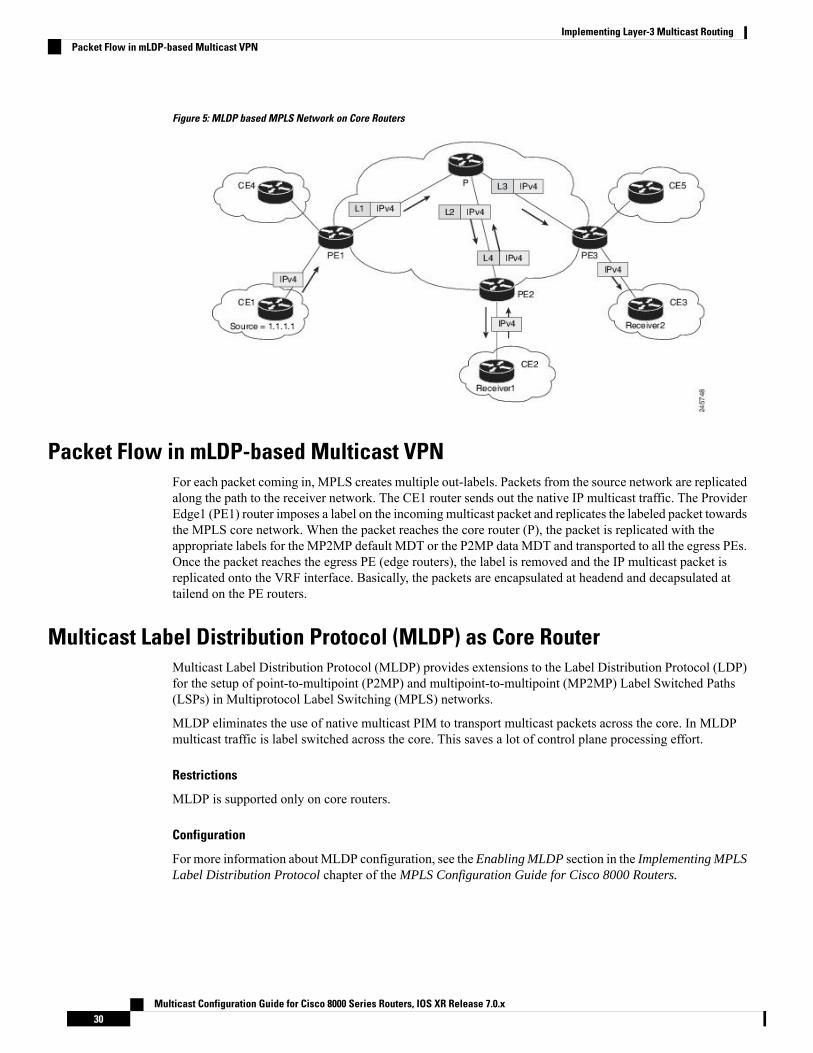
Figure 5: MLDP based MPLS Network on Core Routers
Packet Flow in mLDP-based Multicast VPNFor each packet coming in, MPLS creates multiple out-labels. Packets from the source network are replicatedalong the path to the receiver network. The CE1 router sends out the native IP multicast traffic. The ProviderEdge1 (PE1) router imposes a label on the incoming multicast packet and replicates the labeled packet towardsthe MPLS core network. When the packet reaches the core router (P), the packet is replicated with theappropriate labels for the MP2MP default MDT or the P2MP data MDT and transported to all the egress PEs.Once the packet reaches the egress PE (edge routers), the label is removed and the IP multicast packet isreplicated onto the VRF interface. Basically, the packets are encapsulated at headend and decapsulated attailend on the PE routers.
Multicast Label Distribution Protocol (MLDP) as Core RouterMulticast Label Distribution Protocol (MLDP) provides extensions to the Label Distribution Protocol (LDP)for the setup of point-to-multipoint (P2MP) and multipoint-to-multipoint (MP2MP) Label Switched Paths(LSPs) in Multiprotocol Label Switching (MPLS) networks.
MLDP eliminates the use of native multicast PIM to transport multicast packets across the core. In MLDPmulticast traffic is label switched across the core. This saves a lot of control plane processing effort.
Restrictions
MLDP is supported only on core routers.
Configuration
For more information about MLDP configuration, see the Enabling MLDP section in the Implementing MPLSLabel Distribution Protocol chapter of the MPLS Configuration Guide for Cisco 8000 Routers.
Multicast Configuration Guide for Cisco 8000 Series Routers, IOS XR Release 7.0.x30
Implementing Layer-3 Multicast RoutingPacket Flow in mLDP-based Multicast VPN

Point-to-Multipoint Traffic Engineering Label-Switched MulticastIP multicast was traditionally used for IPTV broadcasting and content delivery services. Point-to-Multipoint(P2MP) Traffic-Engineering is fast replacing the IP multicast technique because of the various advantages ofMPLS-TE, such as:
• Fast re-routing (FRR) and restoration in case of link/ node failure
• Bandwidth guarantee
Restrictions
• P2MP is supported only on core routers.
• FRR is not supported.
• Loop-Free Alternative Fast Reroute is not supported.
Configuration
For more information about Point-to-Multipoint Traffic Engineering Label-SwitchedMulticast configuration,see the Point-to-Multipoint Traffic-Engineering section in the Implementing MPLS Traffic Engineering chapterof the MPLS Configuration Guide for Cisco 8000 Routers.
Multicast Configuration Guide for Cisco 8000 Series Routers, IOS XR Release 7.0.x31
Implementing Layer-3 Multicast RoutingPoint-to-Multipoint Traffic Engineering Label-Switched Multicast

Multicast Configuration Guide for Cisco 8000 Series Routers, IOS XR Release 7.0.x32
Implementing Layer-3 Multicast RoutingPoint-to-Multipoint Traffic Engineering Label-Switched Multicast
Related Documents