Multi Split Trio Quattro Z & E DCI Indoor Units Outdoor Units PNX009 YAZ3 24 DCI YAZ4 30 DCI PNX012 PNX018 CK009 CK012 CK018 SX009 SX012 SX018 DLF009 DLF012 DLF018 XLF009 XLF012 DLS018 PRIME009 PRIME012 PRIME018 HAD009 HAD012 JANUARY – 2012 REFRIGERANT R410A HEAT PUMP SM YAZDCI 1-A.1 GB

Welcome message from author
This document is posted to help you gain knowledge. Please leave a comment to let me know what you think about it! Share it to your friends and learn new things together.
Transcript
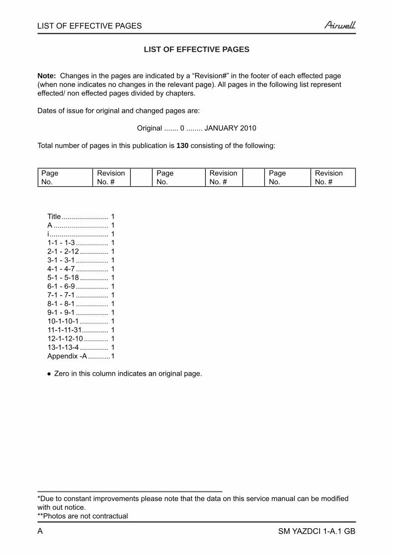
Multi Split Trio Quattro Z & E DCI
Indoor Units Outdoor UnitsPNX009
YAZ3 24 DCI
YAZ4 30 DCI
PNX012PNX018CK009CK012CK018SX009SX012SX018DLF009DLF012DLF018XLF009XLF012DLS018PRIME009PRIME012PRIME018HAD009HAD012
JANUARY – 2012
REFRIGERANT
R410A HEAT PUMP
SM YAZDCI 1-A.1 GB
A
LIST OF EFFECTIVE PAGES
SM YAZDCI 1-A.1 GB
LIST OF EFFECTIVE PAGES
Note: Changes in the pages are indicated by a “Revision#” in the footer of each effected page (when none indicates no changes in the relevant page). All pages in the following list represent effected/ non effected pages divided by chapters.
Dates of issue for original and changed pages are:
Original ....... 0 ........ JANUARY 2010
Total number of pages in this publication is 130 consisting of the following:
PageNo.
RevisionNo. #
PageNo.
RevisionNo. #
PageNo.
RevisionNo. #
Title ....................... 1A ........................... 1i ............................. 11-1 - 1-3 ................ 12-1 - 2-12 .............. 13-1 - 3-1 ................ 14-1 - 4-7 ................ 15-1 - 5-18 .............. 16-1 - 6-9 ................ 17-1 - 7-1 ................ 18-1 - 8-1 ................ 19-1 - 9-1 ................ 110-1-10-1 .............. 111-1-11-31 ............. 112-1-12-10 ............ 113-1-13-4 .............. 1Appendix -A ...........1
● Zero in this column indicates an original page.
*Due to constant improvements please note that the data on this service manual can be modified with out notice.**Photos are not contractual
i
TABLE OF CONTENTS
SM YAZDCI 1-A.1 GB
Table of Contents
1. INTRODUCTION ...................................................................................................1-1
2. PRODUCT DATA SHEET ......................................................................................2-1
3. RATING CONDITIONS ..........................................................................................3-1
4. OUTLINE DIMENSIONS .......................................................................................4-1
5. PERFORMANCE DATA ........................................................................................5-1
6. PRESSURE CURVES ...........................................................................................6-1
7. ELECTRICAL DATA ..............................................................................................7-1
8. WIRING DIAGRAMS & ELECTRICAL CONNECTIONS ......................................8-1
9. REFRIGERATION DIAGRAMS .............................................................................9-1
10. TUBING CONNECTIONS ......................................................................................10-1
11. CONTROL SYSTEM .............................................................................................11-1
12. TROUBLESHOOTING ..........................................................................................12-1
13. EXPLODED VIEWS AND SPARE PARTS LISTS .................................................13-1
14. APPENDIX A .........................................................................................................14-1
1-1
INTRODUCTION
SM YAZDCI 1-A.1 GB
1. INTRODUCTION1.1 GeneralThe Trio/Quattro Z DCI Multi series is a full line multi-tubing system with 3 to 4 connected indoor units. The multi-split inverter is a high level technology product for residential and commercial application offering comfort, low noise operation and energy saving.
1.2 Main Features1.2.1 High Technology
Sine wave form in both OFAN and Compressor drives. DC-BL-SL (Sensor less) Inverter Compressor drive. DC-BL Inverter OFAN drive in the controller. DSP Power (Digital Signal Processing) – High speed calculation for accurate Sine wave form
vector control. Smart PFC control. Fuzzy Logic Control
1.2.2 System Features R410A High COP (“A” class energy rating) Low noise levels IAQ (Indoor Air Quality) features (LEX series) Lego concept - Products line of wall mounted, floor/ceiling, cassette, ducted with capacity
models of 2.5, 3.5 and 5.0 kW. Networking connectivity. Pre-charged system. Dry contact inputs:
o STBYo Night (in cool mode only)o Power Sheddingo Forced Mode operation
Dry contact output – Alarm. Ready for Base heater connection and logic. Cooling operation at outdoor temperature down to -100C. Heating operation at outdoor temperature down to -150C. HMI Display Board (Human-Machine Interface) – 3x7-segment display shows both indoor
and outdoor diagnostics and setting up features. Monitoring softwear (PC port). EEV (Electronic Expansion Valve) for each indoor unit.
1.3 Tubing ConnectionsFlare type interconnecting tubing to be produced on site.For further details please refer to APPENDIX A on this manual, and to the relevant indoor service Manual.
1.4 Inbox DocumentationEach indoor unit is supplied with its own installation and operation manuals.
1-2
INTRODUCTION
SM YAZDCI 1-A.1 GB
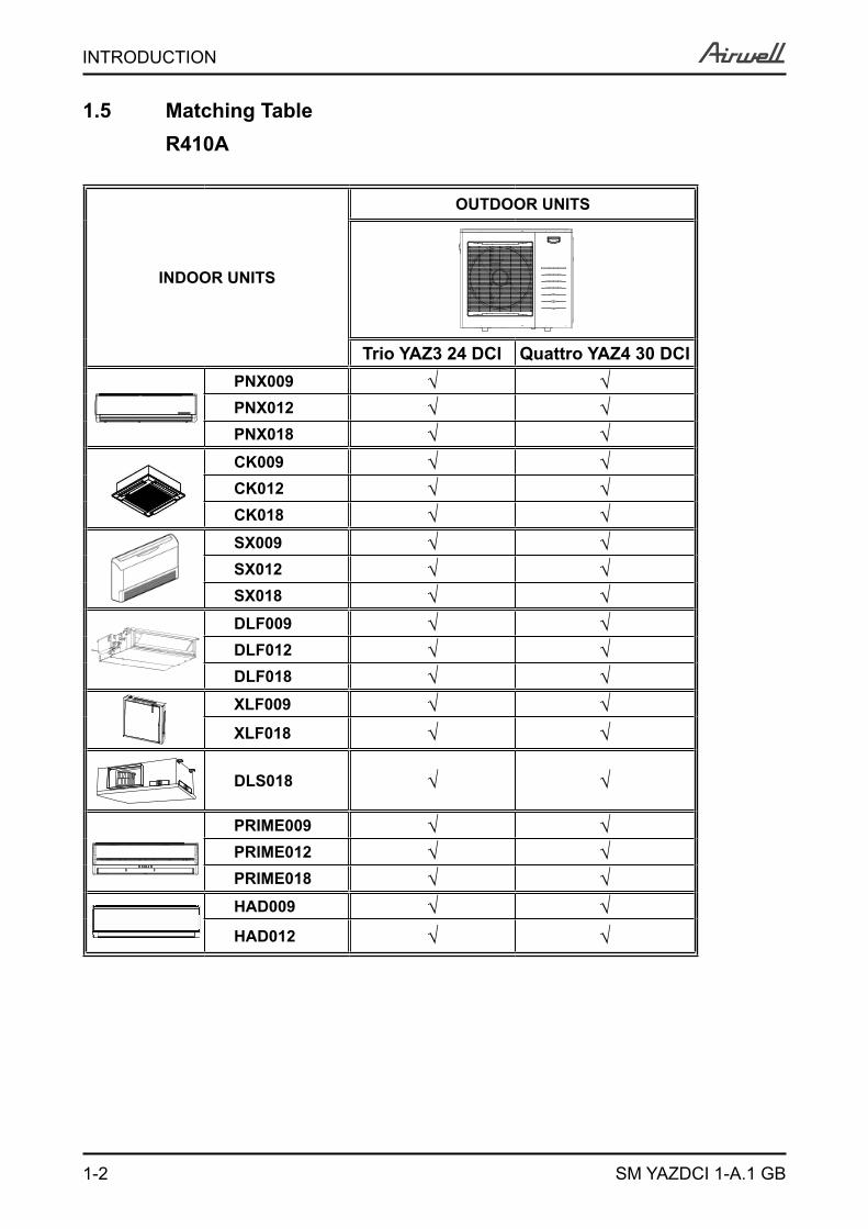
1.5 Matching Table R410A
INDOOR UNITS
OUTDOOR UNITS
Trio YAZ3 24 DCI Quattro YAZ4 30 DCIPNX009 √ √PNX012 √ √PNX018 √ √CK009 √ √CK012 √ √CK018 √ √SX009 √ √SX012 √ √SX018 √ √DLF009 √ √DLF012 √ √DLF018 √ √XLF009 √ √XLF018 √ √
DLS018 √ √
PRIME009 √ √PRIME012 √ √PRIME018 √ √HAD009 √ √HAD012 √ √

1-3
INTRODUCTION
SM YAZDCI 1-A.1 GB
1.6 Indoor Unit combinations
Trio QuattroUnit A Unit B Unit D Code Sum Unit A Unit B Unit C Unit D Code Sum009 009 009 3 009 009 009 009 4009 009 012 3.5 009 009 009 012 4.5009 009 018 4 009 009 012 012 5009 012 012 4 009 009 009 018 5012 012 012 4.5 009 009 012 018 5.5009 012 018 4.5 009 012 012 012 5.5012 012 018 5 009 012 012 018 6
012 012 012 012 6
Nominal Indoor Units Combination
2-1
PRODUCT DATA SHEET
SM YAZDCI 1-A.1 GB
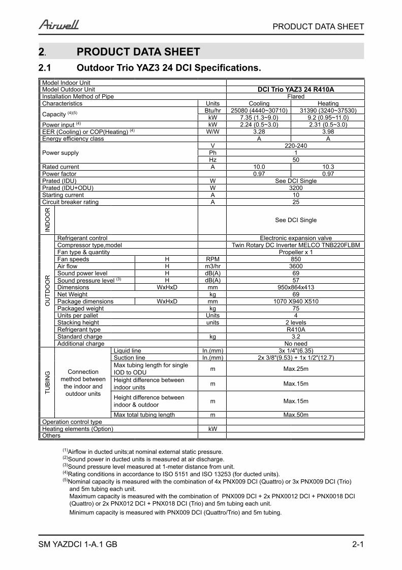
2. PRODUCT DATA SHEET2.1 Outdoor Trio YAZ3 24 DCI Specifications.
Model Indoor Unit Model Outdoor Unit DCI Trio YAZ3 24 R410AInstallation Method of Pipe FlaredCharacteristics Units Cooling Heating
Capacity (4)(5) Btu/hr 25080 (4440~30710) 31390 (3240~37530)kW 7.35 (1.3~9.0) 9.2 (0.95~11.0)
Power input (4) kW 2.24 (0.5~3.0) 2.31 (0.5~3.0)EER (Cooling) or COP(Heating) (4) W/W 3.28 3.98Energy efficiency class A A
Power supplyV 220-240
Ph 1Hz 50
Rated current A 10.0 10.3 Power factor 0.97 0.97Prated (IDU) W See DCI SinglePrated (IDU+ODU) W 3200Starting current A 10Circuit breaker rating A 25
IND
OO
R
See DCI Single
OU
TDO
OR
Refrigerant control Electronic expansion valveCompressor type,model Twin Rotary DC Inverter MELCO TNB220FLBMFan type & quantity Propeller x 1Fan speeds H RPM 850 Air flow H m3/hr 3600Sound power level H dB(A) 69Sound pressure level (3) H dB(A) 57Dimensions WxHxD mm 950x864x413Net Weight kg 69Package dimensions WxHxD mm 1070 X940 X510Packaged weight kg 75Units per pallet Units 4Stacking height units 2 levelsRefrigerant type R410AStandard charge kg 3.2 Additional charge No need
TUB
ING Connection
method between the indoor and
outdoor units
Liquid line In.(mm) 3x 1/4"(6.35)Suction line In.(mm) 2x 3/8"(9.53) + 1x 1/2"(12.7) Max tubing length for singleIOD to ODU m Max.25m
Height difference betweenindoor units m Max.15m
Height difference betweenindoor & outdoor m Max.15m
Max total tubing length m Max.50m Operation control typeHeating elements (Option) kW Others
(1)Airflow in ducted units;at nominal external static pressure. (2)Sound power in ducted units is measured at air discharge. (3)Sound pressure level measured at 1-meter distance from unit. (4)Rating conditions in accordance to ISO 5151 and ISO 13253 (for ducted units). (5)Nominal capacity is measured with the combination of 4x PNX009 DCI (Quattro) or 3x PNX009 DCI (Trio) and 5m tubing each unit. Maximum capacity is measured with the combination of PNX009 DCI + 2x PNX0012 DCI + PNX0018 DCI (Quattro) or 2x PNX012 DCI + PNX018 DCI (Trio) and 5m tubing each unit. Minimum capacity is measured with PNX009 DCI (Quattro/Trio) and 5m tubing.
2-2
PRODUCT DATA SHEET
SM YAZDCI 1-A.1 GB
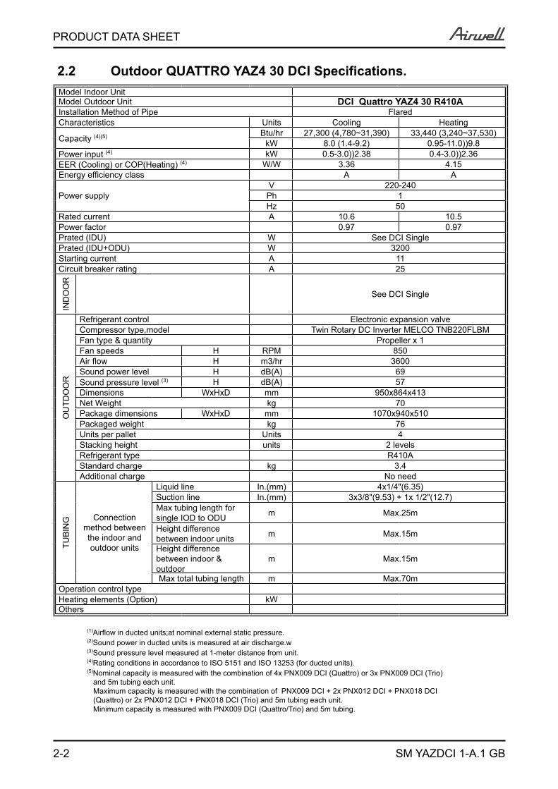
2.2 Outdoor QUATTRO YAZ4 30 DCI Specifications. Model Indoor Unit Model Outdoor Unit DCI Quattro YAZ4 30 R410AInstallation Method of Pipe FlaredCharacteristics Units Cooling Heating
Capacity (4)(5) Btu/hr 27,300 (4,780~31,390) 33,440 (3,240~37,530)kW 8.0 (1.4-9.2) 0.95-11.0))9.8
Power input (4) kW 0.5-3.0))2.38 0.4-3.0))2.36EER (Cooling) or COP(Heating) (4) W/W 3.36 4.15Energy efficiency class A A
Power supplyV 220-240
Ph 1Hz 50
Rated current A 10.6 10.5 Power factor 0.97 0.97Prated (IDU) W See DCI SinglePrated (IDU+ODU) W 3200Starting current A 11Circuit breaker rating A 25
IND
OO
R
See DCI Single
OU
TDO
OR
Refrigerant control Electronic expansion valveCompressor type,model Twin Rotary DC Inverter MELCO TNB220FLBMFan type & quantity Propeller x 1Fan speeds H RPM 850 Air flow H m3/hr 3600Sound power level H dB(A) 69Sound pressure level (3) H dB(A) 57Dimensions WxHxD mm 950x864x413Net Weight kg 70Package dimensions WxHxD mm 1070x940x510Packaged weight kg 76Units per pallet Units 4Stacking height units 2 levelsRefrigerant type R410AStandard charge kg 3.4Additional charge No need
TUB
ING Connection
method between the indoor and
outdoor units
Liquid line In.(mm) 4x1/4"(6.35)Suction line In.(mm) 3x3/8"(9.53) + 1x 1/2"(12.7) Max tubing length forsingle IOD to ODU m Max.25m
Height differencebetween indoor units m Max.15m
Height difference between indoor &outdoor
m Max.15m
Max total tubing length m Max.70m Operation control type Heating elements (Option) kW Others
(1)Airflow in ducted units;at nominal external static pressure. (2)Sound power in ducted units is measured at air discharge.w (3)Sound pressure level measured at 1-meter distance from unit. (4)Rating conditions in accordance to ISO 5151 and ISO 13253 (for ducted units). (5)Nominal capacity is measured with the combination of 4x PNX009 DCI (Quattro) or 3x PNX009 DCI (Trio) and 5m tubing each unit. Maximum capacity is measured with the combination of PNX009 DCI + 2x PNX012 DCI + PNX018 DCI (Quattro) or 2x PNX012 DCI + PNX018 DCI (Trio) and 5m tubing each unit. Minimum capacity is measured with PNX009 DCI (Quattro/Trio) and 5m tubing.
2-3
PRODUCT DATA SHEET
SM YAZDCI 1-A.1 GB
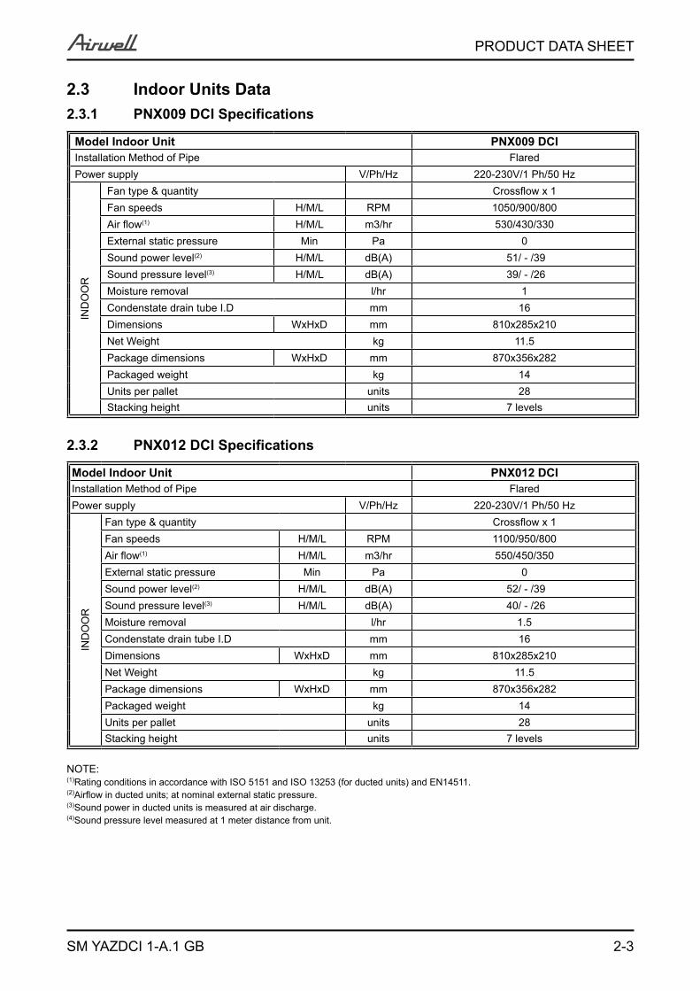
2.3 Indoor Units Data2.3.1 PNX009 DCI Specifications
Model Indoor Unit PNX009 DCIInstallation Method of Pipe FlaredPower supply V/Ph/Hz 220-230V/1 Ph/50 Hz
IND
OO
R
Fan type & quantity Crossflow x 1Fan speeds H/M/L RPM 1050/900/800Air flow(1) H/M/L m3/hr 530/430/330External static pressure Min Pa 0Sound power level(2) H/M/L dB(A) 51/ - /39Sound pressure level(3) H/M/L dB(A) 39/ - /26Moisture removal l/hr 1Condenstate drain tube I.D mm 16Dimensions WxHxD mm 810x285x210Net Weight kg 11.5Package dimensions WxHxD mm 870x356x282Packaged weight kg 14Units per pallet units 28Stacking height units 7 levels
2.3.2 PNX012 DCI Specifications
Model Indoor Unit PNX012 DCIInstallation Method of Pipe FlaredPower supply V/Ph/Hz 220-230V/1 Ph/50 Hz
IND
OO
R
Fan type & quantity Crossflow x 1Fan speeds H/M/L RPM 1100/950/800Air flow(1) H/M/L m3/hr 550/450/350External static pressure Min Pa 0Sound power level(2) H/M/L dB(A) 52/ - /39Sound pressure level(3) H/M/L dB(A) 40/ - /26Moisture removal l/hr 1.5Condenstate drain tube I.D mm 16Dimensions WxHxD mm 810x285x210Net Weight kg 11.5Package dimensions WxHxD mm 870x356x282Packaged weight kg 14Units per pallet units 28Stacking height units 7 levels
NOTE:(1)Rating conditions in accordance with ISO 5151 and ISO 13253 (for ducted units) and EN14511.(2)Airflow in ducted units; at nominal external static pressure.(3)Sound power in ducted units is measured at air discharge.(4)Sound pressure level measured at 1 meter distance from unit.

2-4
PRODUCT DATA SHEET
SM YAZDCI 1-A.1 GB
2.3.3 PNX018 DCI Specifications
Model Indoor Unit PNX018 DCIInstallation Method of Pipe FlaredPower supply V/Ph/Hz 220-230V/1 Ph/50 Hz
IND
OO
R
Fan type & quantity Crossflow x 1Fan speeds H/M/L RPM 1200/1050/900Air flow(1) H/M/L m3/hr 850/700/550External static pressure Min Pa 0Sound power level(2) H/M/L dB(A) 55/51/47Sound pressure level(3) H/M/L dB(A) 43/39/34Moisture removal l/hr 2Condenstate drain tube I.D mm 16Dimensions WxHxD mm 1060x295x221Net Weight kg 15Package dimensions WxHxD mm 1125x360x295Packaged weight kg 18Units per pallet units 16Stacking height units 8 levels
2.3.4 CK009 DCI Specifications
Model Indoor Unit CK012 DCIInstallation Method of Pipe FlaredPower supply V/Ph/Hz 220-230V/1 Ph/50 Hz
IND
OO
R
Fan type & quantity Centrifugal x 1Fan speeds H/M/L RPM 550/500/450 600/520/450Air flow(1) H/M/L m3/hr 420/370/320 470/390/320External static pressure Min Pa 0Sound power level(2) H/M/L dB(A) 49 49Sound pressure level(3) H/M/L dB(A) 32/30/28 34/31/28Moisture removal l/hr 0.7Condenstate drain tube I.D mm 20Dimensions WxHxD mm 575X575X219(625X625X40/725X725X40)Net Weight kg 12.9(2.2/2.7)Package dimensions WxHxD mm 681X681X297(700X700X103/800X800X103)Packaged weight kg 16.2(3.4/4.2)Units per pallet units 12Stacking height units 6 levels
NOTE:(1)Rating conditions in accordance with ISO 5151 and ISO 13253 (for ducted units) and EN14511.(2)Airflow in ducted units; at nominal external static pressure.(3)Sound power in ducted units is measured at air discharge.(4)Sound pressure level measured at 1 meter distance from unit.
2-5
PRODUCT DATA SHEET
SM YAZDCI 1-A.1 GB
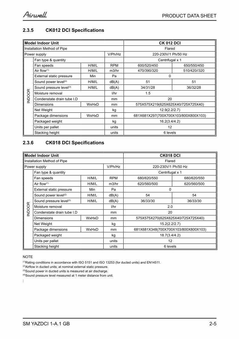
2.3.5 CK012 DCI Specifications
Model Indoor Unit CK 012 DCIInstallation Method of Pipe FlaredPower supply V/Ph/Hz 220-230V/1 Ph/50 Hz
IND
OO
R
Fan type & quantity Centrifugal x 1Fan speeds H/M/L RPM 600/520/450 650/550/450Air flow(1) H/M/L m3/hr 470/390/320 510/420//320External static pressure Min Pa 0Sound power level(2) H/M/L dB(A) 51 51Sound pressure level(3) H/M/L dB(A) 34/31/28 36/32/28Moisture removal l/hr 1.5Condenstate drain tube I.D mm 20Dimensions WxHxD mm 575X575X219(625X625X40/725X725X40)Net Weight kg 12.9(2.2/2.7)Package dimensions WxHxD mm 681X681X297(700X700X103/800X800X103)Packaged weight kg 16.2(3.4/4.2)Units per pallet units 12Stacking height units 6 levels
2.3.6 CK018 DCI Specifications
Model Indoor Unit CK018 DCIInstallation Method of Pipe FlaredPower supply V/Ph/Hz 220-230V/1 Ph/50 Hz
IND
OO
R
Fan type & quantity Centrifugal x 1Fan speeds H/M/L RPM 680/620/550 680/620/550Air flow(1) H/M/L m3/hr 620/560/500 620/560/500External static pressure Min Pa 0Sound power level(2) H/M/L dB(A) 54 54Sound pressure level(3) H/M/L dB(A) 36/33/30 36/33/30Moisture removal l/hr 2.0 Condenstate drain tube I.D mm 20Dimensions WxHxD mm 575X575X270(625X625X40/725X725X40)Net Weight kg 15.2(2.2/2.7)Package dimensions WxHxD mm 681X681X348(700X700X103/800X800X103)Packaged weight kg 18.7(3.4/4.2)Units per pallet units 12Stacking height units 6 levels
NOTE(1)Rating conditions in accordance with ISO 5151 and ISO 13253 (for ducted units) and EN14511.(2)Airflow in ducted units; at nominal external static pressure.(3)Sound power in ducted units is measured at air discharge.(4)Sound pressure level measured at 1 meter distance from unit.:

2-6
PRODUCT DATA SHEET
SM YAZDCI 1-A.1 GB
2.3.7 SX009 DCI Specifications
Model Indoor Unit SX009 DCI Installation Method of Pipe FlaredPower supply V/Ph/Hz 220-240/1/50
IND
OO
R
Fan type & quantity Centifugal x 2Fan speeds H/M/L RPM 760/670/500Air flow(1) H/M/L m3/hr 400/350/300External static pressure Min Pa 0Sound power level(2) H/M/L dB(A) 54/49/41Sound pressure level(3) H/M/L dB(A) 42/37/29Moisture removal l/hr 1Condenstate drain tube I.D mm 16Dimensions WxHxD mm 820x630x190Net Weight kg 21Package dimensions WxHxD mm 920x726x273Package weight kg 25Units per pallet units 14units per palletUnits stacking units 7 levels
2.3.8 SX012 DCI Specifications
Model Indoor Unit SX012 DCI Installation Method of Pipe FlaredPower supply V/Ph/Hz 220-240/1/50
IND
OO
R
Fan type & quantity Centifugal x 2Fan speeds H/M/L RPM 830/760/500Air flow(1) H/M/L m3/hr 450/400/300External static pressure Min Pa 0Sound power level(2) H/M/L dB(A) 56/53/41Sound pressure level(3) H/M/L dB(A) 45/41/30Moisture removal l/hr 1.5Condenstate drain tube I.D mm 16Dimensions WxHxD mm 820x630x190Net Weight kg 22Package dimensions WxHxD mm 920x726x273Package weight kg 26Units per pallet units 14units per palletUnits stacking units 7 levels
NOTE:(1)Rating conditions in accordance with ISO 5151 and ISO 13253 (for ducted units) and EN14511.(2)Airflow in ducted units; at nominal external static pressure.(3)Sound power in ducted units is measured at air discharge.(4)Sound pressure level measured at 1 meter distance from unit.
2-7
PRODUCT DATA SHEET
SM YAZDCI 1-A.1 GB
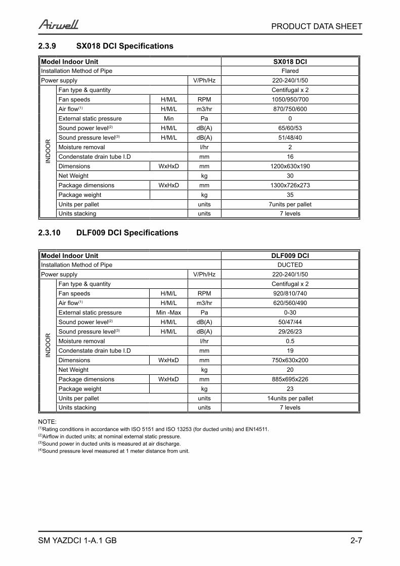
2.3.9 SX018 DCI Specifications
Model Indoor Unit SX018 DCI Installation Method of Pipe FlaredPower supply V/Ph/Hz 220-240/1/50
IND
OO
R
Fan type & quantity Centifugal x 2Fan speeds H/M/L RPM 1050/950/700Air flow(1) H/M/L m3/hr 870/750/600External static pressure Min Pa 0Sound power level(2) H/M/L dB(A) 65/60/53Sound pressure level(3) H/M/L dB(A) 51/48/40Moisture removal l/hr 2Condenstate drain tube I.D mm 16Dimensions WxHxD mm 1200x630x190Net Weight kg 30Package dimensions WxHxD mm 1300x726x273Package weight � kg 35Units per pallet units 7units per palletUnits stacking units 7 levels
2.3.10 DLF009 DCI Specifications
Model Indoor Unit DLF009 DCI Installation Method of Pipe DUCTEDPower supply V/Ph/Hz 220-240/1/50
IND
OO
R
Fan type & quantity Centifugal x 2Fan speeds H/M/L RPM 920/810/740Air flow(1) H/M/L m3/hr 620/560/490External static pressure Min -Max Pa 0-30Sound power level(2) H/M/L dB(A) 50/47/44Sound pressure level(3) H/M/L dB(A) 29/26/23Moisture removal l/hr 0.5Condenstate drain tube I.D mm 19Dimensions WxHxD mm 750x630x200Net Weight kg 20Package dimensions WxHxD mm 885x695x226Package weight kg 23Units per pallet units 14units per palletUnits stacking units 7 levels
NOTE:(1)Rating conditions in accordance with ISO 5151 and ISO 13253 (for ducted units) and EN14511.(2)Airflow in ducted units; at nominal external static pressure.(3)Sound power in ducted units is measured at air discharge.(4)Sound pressure level measured at 1 meter distance from unit.
2-8
PRODUCT DATA SHEET
SM YAZDCI 1-A.1 GB
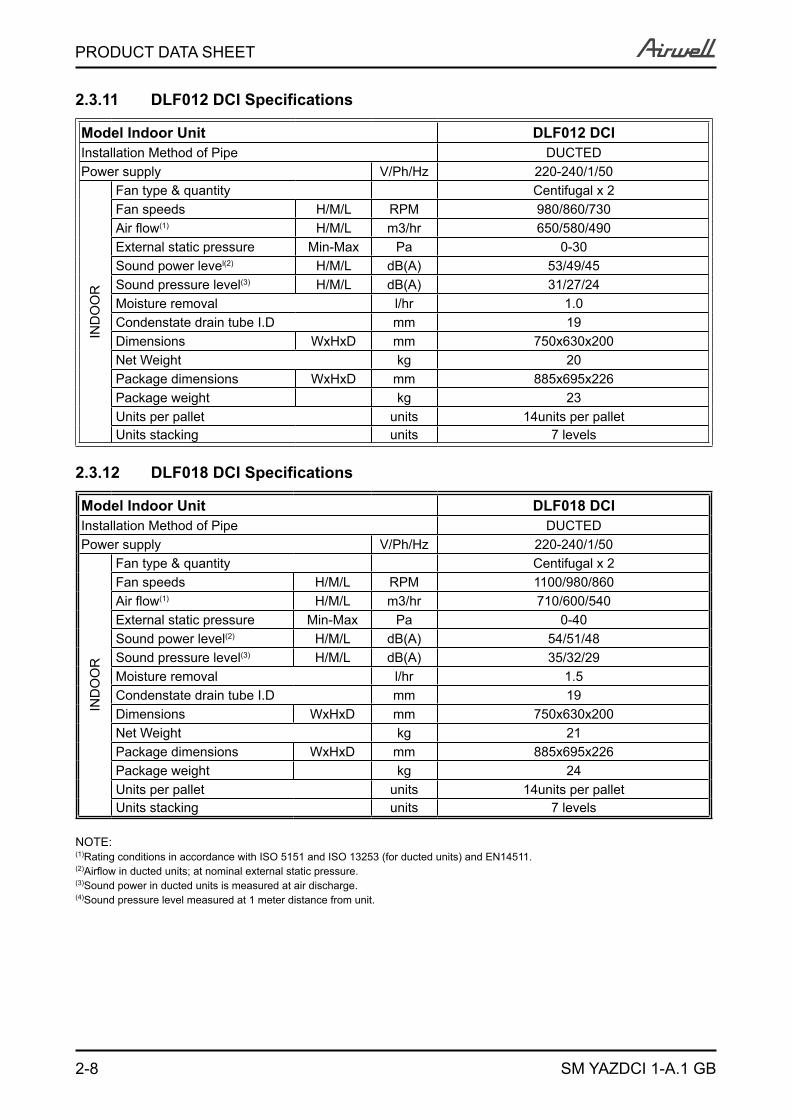
2.3.11 DLF012 DCI Specifications
Model Indoor Unit DLF012 DCI Installation Method of Pipe DUCTEDPower supply V/Ph/Hz 220-240/1/50
IND
OO
R
Fan type & quantity Centifugal x 2Fan speeds H/M/L RPM 980/860/730Air flow(1) H/M/L m3/hr 650/580/490External static pressure Min-Max Pa 0-30Sound power level(2) H/M/L dB(A) 53/49/45Sound pressure level(3) H/M/L dB(A) 31/27/24Moisture removal l/hr 1.0 Condenstate drain tube I.D mm 19Dimensions WxHxD mm 750x630x200Net Weight kg 20Package dimensions WxHxD mm 885x695x226Package weight kg 23Units per pallet units 14units per palletUnits stacking units 7 levels
2.3.12 DLF018 DCI Specifications
Model Indoor Unit DLF018 DCI Installation Method of Pipe DUCTEDPower supply V/Ph/Hz 220-240/1/50
IND
OO
R
Fan type & quantity Centifugal x 2Fan speeds H/M/L RPM 1100/980/860Air flow(1) H/M/L m3/hr 710/600/540External static pressure Min-Max Pa 0-40Sound power level(2) H/M/L dB(A) 54/51/48Sound pressure level(3) H/M/L dB(A) 35/32/29Moisture removal l/hr 1.5Condenstate drain tube I.D mm 19Dimensions WxHxD mm 750x630x200Net Weight kg 21Package dimensions WxHxD mm 885x695x226Package weight kg 24Units per pallet units 14units per palletUnits stacking units 7 levels
NOTE:(1)Rating conditions in accordance with ISO 5151 and ISO 13253 (for ducted units) and EN14511.(2)Airflow in ducted units; at nominal external static pressure.(3)Sound power in ducted units is measured at air discharge.(4)Sound pressure level measured at 1 meter distance from unit.
2-9
PRODUCT DATA SHEET
SM YAZDCI 1-A.1 GB
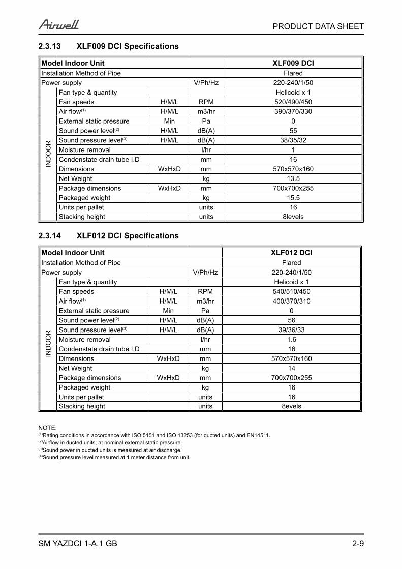
2.3.13 XLF009 DCI Specifications
Model Indoor Unit XLF009 DCIInstallation Method of Pipe FlaredPower supply V/Ph/Hz 220-240/1/50
IND
OO
R
Fan type & quantity Helicoid x 1Fan speeds H/M/L RPM 520/490/450Air flow(1) H/M/L m3/hr 390/370/330External static pressure Min Pa 0Sound power level(2) H/M/L dB(A) 55Sound pressure level(3) H/M/L dB(A) 38/35/32Moisture removal l/hr 1Condenstate drain tube I.D mm 16Dimensions WxHxD mm 570x570x160Net Weight kg 13.5Package dimensions WxHxD mm 700x700x255Packaged weight kg 15.5Units per pallet units 16Stacking height units 8levels
2.3.14 XLF012 DCI Specifications
Model Indoor Unit XLF012 DCIInstallation Method of Pipe FlaredPower supply V/Ph/Hz 220-240/1/50
IND
OO
R
Fan type & quantity Helicoid x 1Fan speeds H/M/L RPM 540/510/450Air flow(1) H/M/L m3/hr 400/370/310External static pressure Min Pa 0Sound power level(2) H/M/L dB(A) 56Sound pressure level(3) H/M/L dB(A) 39/36/33Moisture removal l/hr 1.6Condenstate drain tube I.D mm 16Dimensions WxHxD mm 570x570x160Net Weight kg 14Package dimensions WxHxD mm 700x700x255Packaged weight kg 16Units per pallet units 16Stacking height units 8evels
NOTE:(1)Rating conditions in accordance with ISO 5151 and ISO 13253 (for ducted units) and EN14511.(2)Airflow in ducted units; at nominal external static pressure.(3)Sound power in ducted units is measured at air discharge.(4)Sound pressure level measured at 1 meter distance from unit.
2-10
PRODUCT DATA SHEET
SM YAZDCI 1-A.1 GB
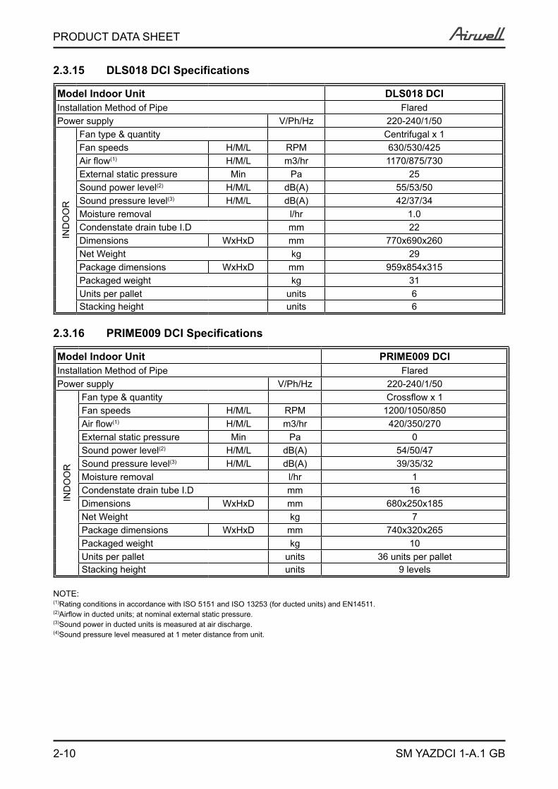
2.3.15 DLS018 DCI Specifications
Model Indoor Unit DLS018 DCIInstallation Method of Pipe FlaredPower supply V/Ph/Hz 220-240/1/50
IND
OO
R
Fan type & quantity Centrifugal x 1Fan speeds H/M/L RPM 630/530/425Air flow(1) H/M/L m3/hr 1170/875/730External static pressure Min Pa 25Sound power level(2) H/M/L dB(A) 55/53/50Sound pressure level(3) H/M/L dB(A) 42/37/34Moisture removal l/hr 1.0 Condenstate drain tube I.D mm 22Dimensions WxHxD mm 770x690x260Net Weight kg 29Package dimensions WxHxD mm 959x854x315Packaged weight kg 31Units per pallet units 6Stacking height units 6
2.3.16 PRIME009 DCI Specifications
Model Indoor Unit PRIME009 DCIInstallation Method of Pipe FlaredPower supply V/Ph/Hz 220-240/1/50
IND
OO
R
Fan type & quantity Crossflow x 1Fan speeds H/M/L RPM 1200/1050/850Air flow(1) H/M/L m3/hr 420/350/270External static pressure Min Pa 0Sound power level(2) H/M/L dB(A) 54/50/47Sound pressure level(3) H/M/L dB(A) 39/35/32Moisture removal l/hr 1Condenstate drain tube I.D mm 16Dimensions WxHxD mm 680x250x185Net Weight kg 7Package dimensions WxHxD mm 740x320x265Packaged weight kg 10Units per pallet units 36 units per palletStacking height units 9 levels
NOTE:(1)Rating conditions in accordance with ISO 5151 and ISO 13253 (for ducted units) and EN14511.(2)Airflow in ducted units; at nominal external static pressure.(3)Sound power in ducted units is measured at air discharge.(4)Sound pressure level measured at 1 meter distance from unit.
2-11
PRODUCT DATA SHEET
SM YAZDCI 1-A.1 GB
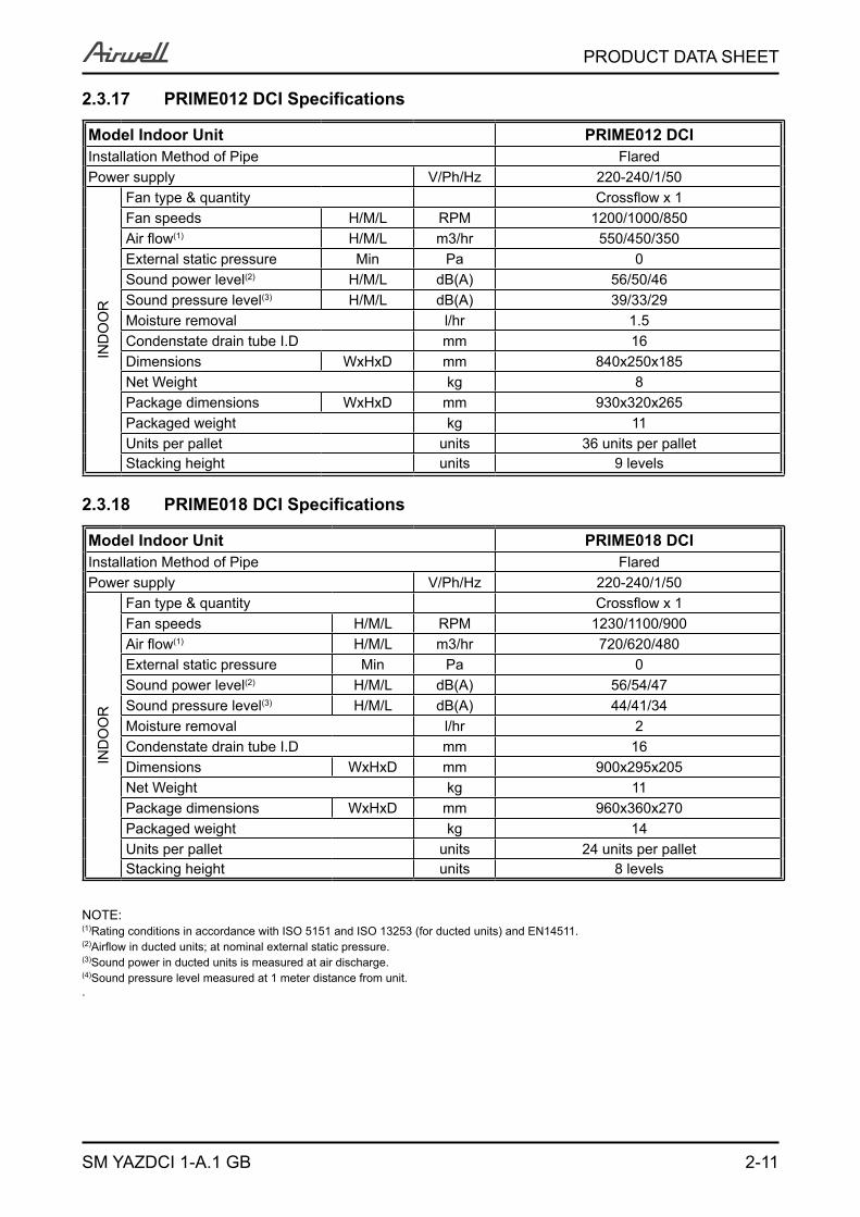
2.3.17 PRIME012 DCI Specifications
Model Indoor Unit PRIME012 DCIInstallation Method of Pipe FlaredPower supply V/Ph/Hz 220-240/1/50
IND
OO
R
Fan type & quantity Crossflow x 1Fan speeds H/M/L RPM 1200/1000/850Air flow(1) H/M/L m3/hr 550/450/350External static pressure Min Pa 0Sound power level(2) H/M/L dB(A) 56/50/46Sound pressure level(3) H/M/L dB(A) 39/33/29Moisture removal l/hr 1.5Condenstate drain tube I.D mm 16Dimensions WxHxD mm 840x250x185Net Weight kg 8Package dimensions WxHxD mm 930x320x265Packaged weight kg 11Units per pallet units 36 units per palletStacking height units 9 levels
2.3.18 PRIME018 DCI Specifications
Model Indoor Unit PRIME018 DCIInstallation Method of Pipe FlaredPower supply V/Ph/Hz 220-240/1/50
IND
OO
R
Fan type & quantity Crossflow x 1Fan speeds H/M/L RPM 1230/1100/900Air flow(1) H/M/L m3/hr 720/620/480External static pressure Min Pa 0Sound power level(2) H/M/L dB(A) 56/54/47Sound pressure level(3) H/M/L dB(A) 44/41/34Moisture removal l/hr 2Condenstate drain tube I.D mm 16Dimensions WxHxD mm 900x295x205Net Weight kg 11Package dimensions WxHxD mm 960x360x270Packaged weight kg 14Units per pallet units 24 units per palletStacking height units 8 levels
NOTE:(1)Rating conditions in accordance with ISO 5151 and ISO 13253 (for ducted units) and EN14511.(2)Airflow in ducted units; at nominal external static pressure.(3)Sound power in ducted units is measured at air discharge.(4)Sound pressure level measured at 1 meter distance from unit..
2-12
PRODUCT DATA SHEET
SM YAZDCI 1-A.1 GB
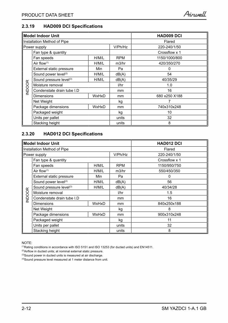
2.3.19 HAD009 DCI Specifications
Model Indoor Unit HAD009 DCIInstallation Method of Pipe FlaredPower supply V/Ph/Hz 220-240/1/50
IND
OO
R
Fan type & quantity Crossflow x 1Fan speeds H/M/L RPM 1150/1000/800Air flow(1) H/M/L m3/hr 420/350/270External static pressure Min Pa 0Sound power level(2) H/M/L dB(A) 54Sound pressure level(3) H/M/L dB(A) 40/35/29Moisture removal l/hr 1.0 Condenstate drain tube I.D mm 16Dimensions WxHxD mm 680 x250 X188Net Weight kg 7Package dimensions WxHxD mm 740x310x248Packaged weight kg 10Units per pallet units 32Stacking height units 8
2.3.20 HAD012 DCI Specifications
Model Indoor Unit HAD012 DCIInstallation Method of Pipe FlaredPower supply V/Ph/Hz 220-240/1/50
IND
OO
R
Fan type & quantity Crossflow x 1Fan speeds H/M/L RPM 1150/950/750Air flow(1) H/M/L m3/hr 550/450/350External static pressure Min Pa 0Sound power level(2) H/M/L dB(A) 56Sound pressure level(3) H/M/L dB(A) 40/34/28Moisture removal l/hr 1.5 Condenstate drain tube I.D mm 16Dimensions WxHxD mm 840x250x188Net Weight kg 8Package dimensions WxHxD mm 900x310x248Packaged weight kg 11Units per pallet units 32Stacking height units 8
NOTE:(1)Rating conditions in accordance with ISO 5151 and ISO 13253 (for ducted units) and EN14511.(2)Airflow in ducted units; at nominal external static pressure.(3)Sound power in ducted units is measured at air discharge.(4)Sound pressure level measured at 1 meter distance from unit.
3-1
RATING CONDITIONS
SM YAZDCI 1-A.1 GB
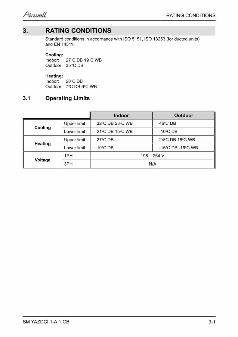
3. RATING CONDITIONSStandard conditions in accordance with ISO 5151, ISO 13253 (for ducted units) and EN 14511.
Cooling:Indoor: 27oC DB 19oC WBOutdoor: 35 oC DB
Heating:Indoor: 20oC DB Outdoor: 7oC DB 6oC WB
3.1 Operating Limits
Indoor Outdoor
CoolingUpper limit 32oC DB 23oC WB 46oC DB
Lower limit 21oC DB 15oC WB -10oC DB
HeatingUpper limit 27oC DB 24oC DB 18oC WB
Lower limit 10oC DB -15oC DB -16oC WB
Voltage1PH 198 – 264 V
3PH N/A
4-1
OUTLINE DIMENSIONS
SM YAZDCI 1-A.1 GB
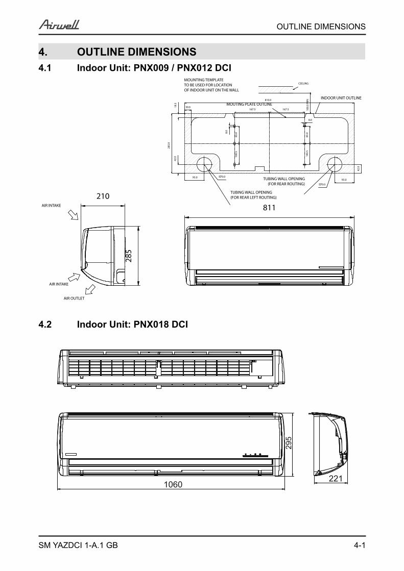
4. OUTLINE DIMENSIONS4.1 Indoor Unit: PNX009 / PNX012 DCI
4.2 Indoor Unit: PNX018 DCI
1060221
295
AIR INTAKE
AIR INTAKE
AIR OUTLET
210
285
811
CEELING
8.0
83.0
167.5 100.
0 M
IN
83.08.
0
18.5
30.0MOUTING PLATE OUTLINE
MOUNTING TEMPLATETO BE USED FOR LOCATIONOF INDOOR UNIT ON THE WALL
167.5
810.0INDOOR UNIT OUTLINE
42.0
TUBING WALL OPENING(FOR REAR ROUTING)
�70.093.0
TUBING WALL OPENING(FOR REAR LEFT ROUTING)
93.0
�70.0
100.
5
285.
0
42.0 10
0.5
4-2
OUTLINE DIMENSIONS
SM YAZDCI 1-A.1 GB
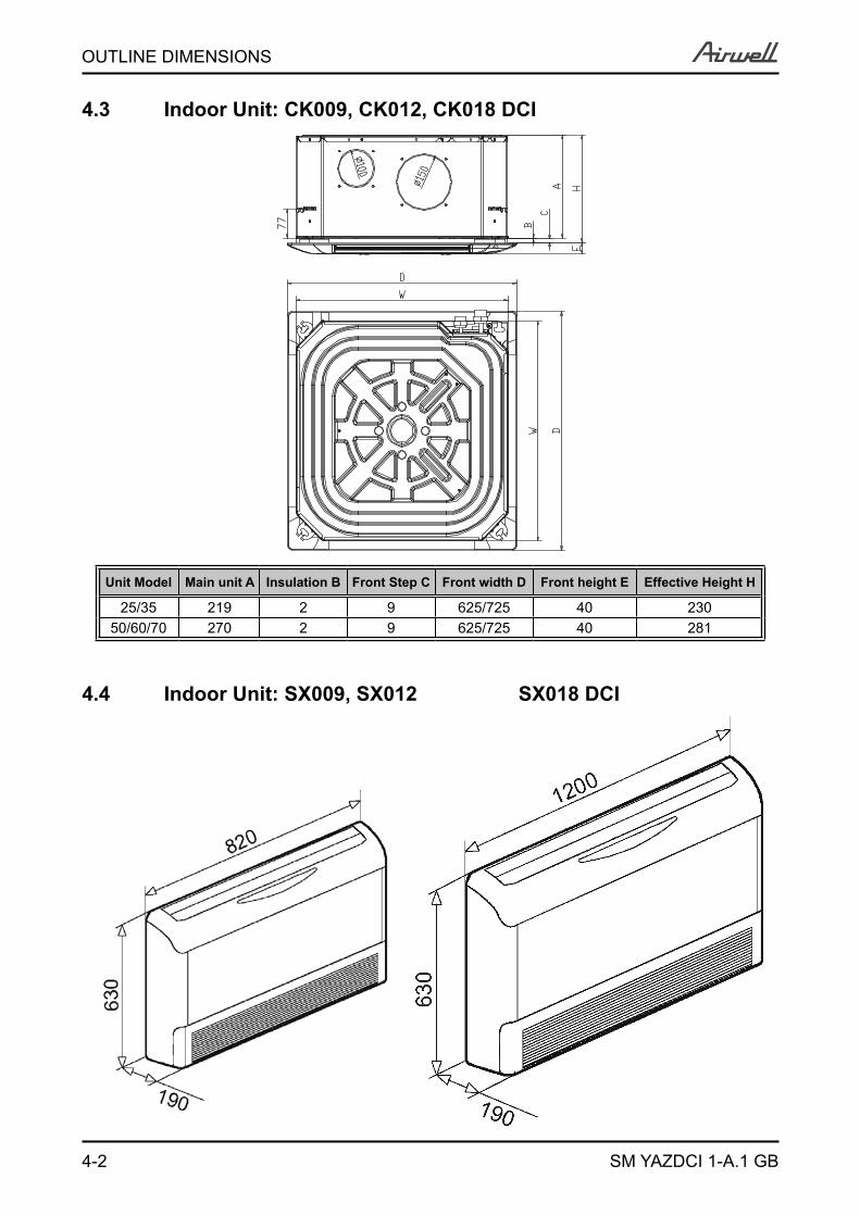
4.3 Indoor Unit: CK009, CK012, CK018 DCI
4.4 Indoor Unit: SX009, SX012 SX018 DCI
Unit Model Main unit A Insulation B Front Step C Front width D Front height E Effective Height H
25/35 219 2 9 625/725 40 23050/60/70 270 2 9 625/725 40 281
4-3
OUTLINE DIMENSIONS
SM YAZDCI 1-A.1 GB
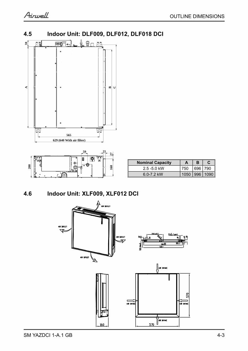
4.5 Indoor Unit: DLF009, DLF012, DLF018 DCI
4.6 Indoor Unit: XLF009, XLF012 DCI
A C
565
B
629 (640 With air filter)
59
21
200
2716
0
59
Nominal Capacity A B C2.5 -5.0 kW 750 696 7906.0-7.2 kW 1050 996 1090
4-4
OUTLINE DIMENSIONS
SM YAZDCI 1-A.1 GB
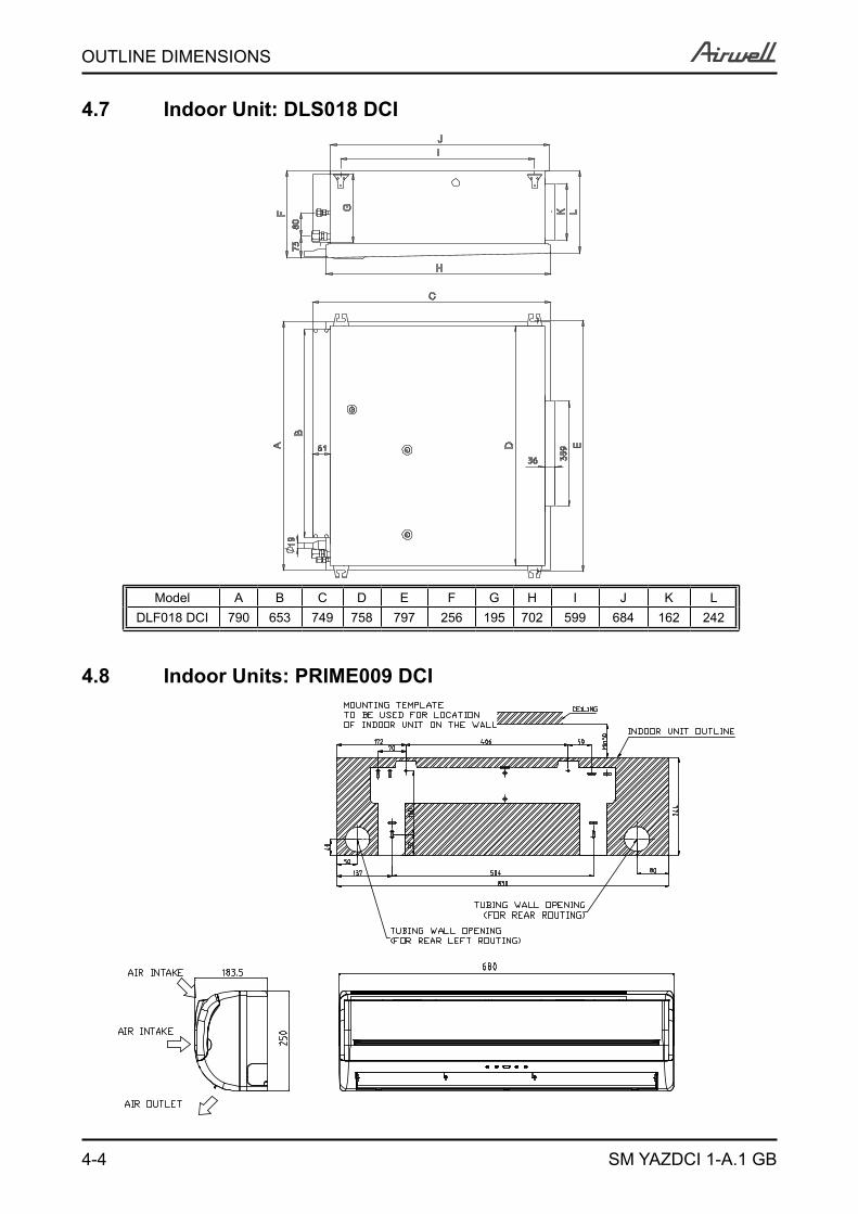
4.7 Indoor Unit: DLS018 DCI
Model A B C D E F G H I J K LDLF018 DCI 790 653 749 758 797 256 195 702 599 684 162 242
4.8 Indoor Units: PRIME009 DCI
4-5
OUTLINE DIMENSIONS
SM YAZDCI 1-A.1 GB
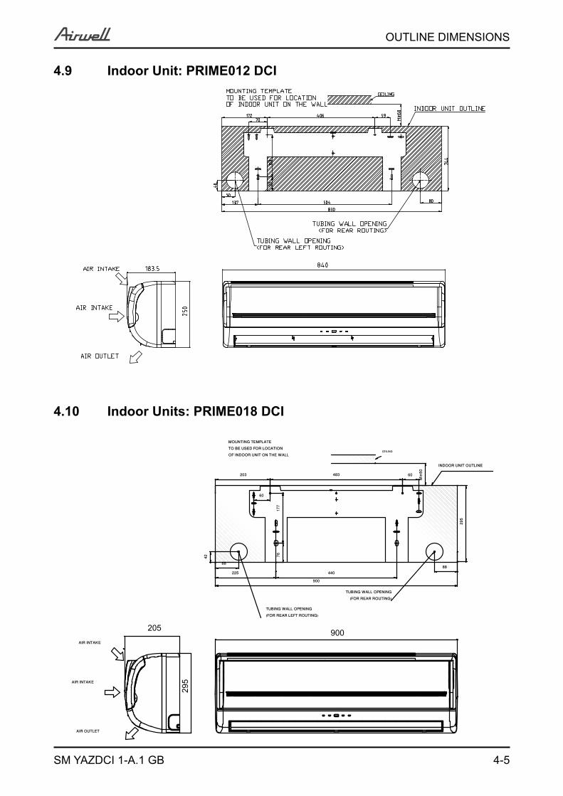
4.9 Indoor Unit: PRIME012 DCI
4.10 Indoor Units: PRIME018 DCI
900
295AIR INTAKE
AIR INTAKE
AIR OUTLET
205
MOUNTING TEMPLATETO BE USED FOR LOCATIONOF INDOOR UNIT ON THE WALL
CEILING
Min
50
INDOOR UNIT OUTLINE
TUBING WALL OPENING(FOR REAR LEFT ROUTING)
TUBING WALL OPENING(FOR REAR ROUTING)
8888
440225
483 60203
42
900
177
60
295
76
4-6
OUTLINE DIMENSIONS
SM YAZDCI 1-A.1 GB
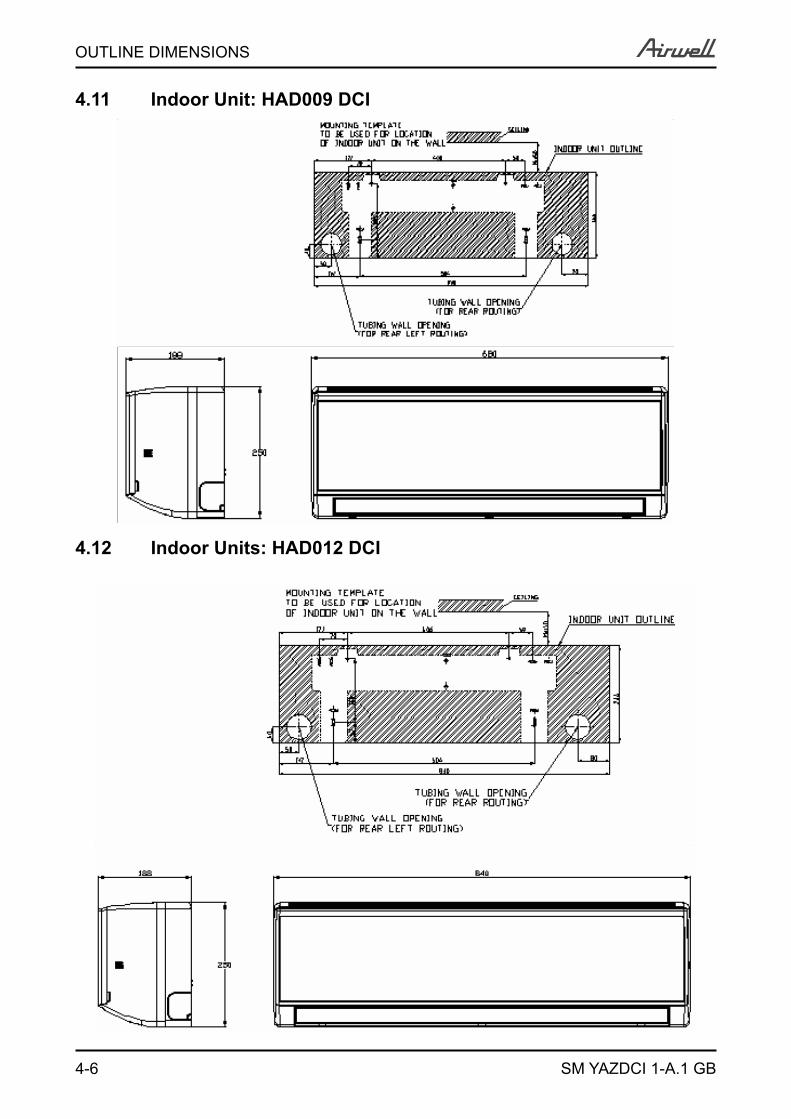
4.11 Indoor Unit: HAD009 DCI
4.12 Indoor Units: HAD012 DCI
4-7
OUTLINE DIMENSIONS
SM YAZDCI 1-A.1 GB
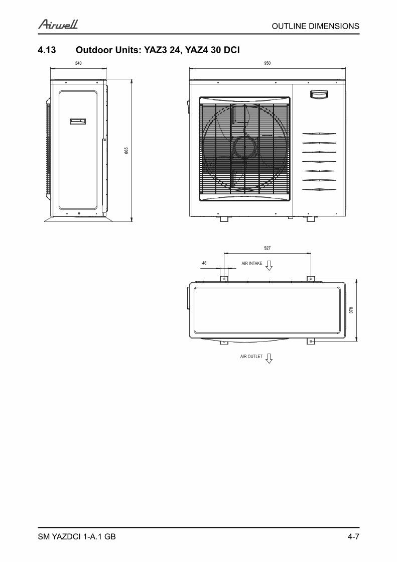
378
48
527
865
950340
AIR INTAKE
AIR OUTLET
4.13 Outdoor Units: YAZ3 24, YAZ4 30 DCI

5-1
PERFORMANCE DATA
SM YAZDCI 1-A.1 GB
5. PERFORMANCE DATA5.1 Outdoor Unit YAZ3 24 DCI Combinations (Based on PNX)5.1.1 Cooling
ModelCooling Capacity [KW] Power Consumption
[W] COPNominal
Energy Efficiency
ClassA B D Nom. Min. Max. Nom. Min. Max.
25 - - 2.50 2.50 1.30 3.70 685 500 1,025 3.65 A
35 - - 3.50 3.50 1.30 4.40 968 500 1,223 3.62 A
50 - - 5.00 5.00 1.49 5.93 1,393 566 1,656 3.59 A
25+25 - 2.60 2.60 5.19 1.86 6.56 1,532 683 1,856 3.39 A
25+35 - 2.62 3.49 6.11 1.86 7.73 1,823 683 2,541 3.35 A
25+50 - 2.49 4.98 7.47 1.86 9.00 2,251 659 3,046 3.32 A
35+35 - 3.53 3.53 7.06 1.86 9.00 2,120 683 2,246 3.33 A
35+50 - 2.99 4.48 7.47 1.86 9.00 2,251 659 3,055 3.32 A
25+25+25 2.45 2.45 2.45 7.35 2.69 8.98 2,240 949 3,049 3.28 A
25+25+35 2.25 2.25 2.99 7.48 2.69 9.00 2,281 949 3,157 3.28 A
25+25+50 1.87 1.87 3.74 7.47 2.69 9.00 2,278 962 3,097 3.28 A
25+35+35 2.04 2.71 2.71 7.46 2.69 9.00 2,275 949 3,097 3.28 A
25+35+50 1.72 2.30 3.45 7.46 2.69 9.00 2,275 962 3,061 3.28 A
35+35+35 2.49 2.49 2.49 7.47 2.69 9.00 2,278 990 3,085 3.28 A
35+35+50 2.13 2.13 3.19 7.45 2.69 9.00 2,272 962 3,086 3.28 A
Nominal Indoor Units Combination
5-2
PERFORMANCE DATA
SM YAZDCI 1-A.1 GB
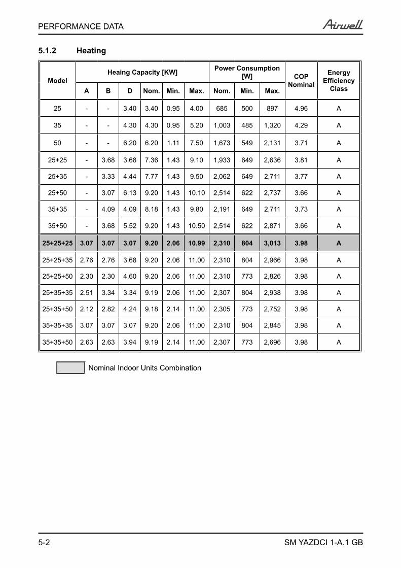
5.1.2 Heating
ModelHeaing Capacity [KW] Power Consumption
[W] COPNominal
Energy Efficiency
ClassA B D Nom. Min. Max. Nom. Min. Max.
25 - - 3.40 3.40 0.95 4.00 685 500 897 4.96 A
35 - - 4.30 4.30 0.95 5.20 1,003 485 1,320 4.29 A
50 - - 6.20 6.20 1.11 7.50 1,673 549 2,131 3.71 A
25+25 - 3.68 3.68 7.36 1.43 9.10 1,933 649 2,636 3.81 A
25+35 - 3.33 4.44 7.77 1.43 9.50 2,062 649 2,711 3.77 A
25+50 - 3.07 6.13 9.20 1.43 10.10 2,514 622 2,737 3.66 A
35+35 - 4.09 4.09 8.18 1.43 9.80 2,191 649 2,711 3.73 A
35+50 - 3.68 5.52 9.20 1.43 10.50 2,514 622 2,871 3.66 A
25+25+25 3.07 3.07 3.07 9.20 2.06 10.99 2,310 804 3,013 3.98 A
25+25+35 2.76 2.76 3.68 9.20 2.06 11.00 2,310 804 2,966 3.98 A
25+25+50 2.30 2.30 4.60 9.20 2.06 11.00 2,310 773 2,826 3.98 A
25+35+35 2.51 3.34 3.34 9.19 2.06 11.00 2,307 804 2,938 3.98 A
25+35+50 2.12 2.82 4.24 9.18 2.14 11.00 2,305 773 2,752 3.98 A
35+35+35 3.07 3.07 3.07 9.20 2.06 11.00 2,310 804 2,845 3.98 A
35+35+50 2.63 2.63 3.94 9.19 2.14 11.00 2,307 773 2,696 3.98 A
Nominal Indoor Units Combination
5-3
PERFORMANCE DATA
SM YAZDCI 1-A.1 GB
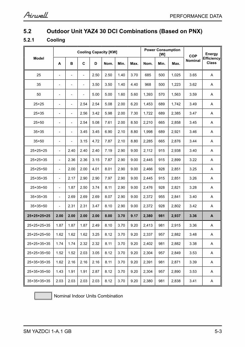
5.2 Outdoor Unit YAZ4 30 DCI Combinations (Based on PNX)5.2.1 Cooling
ModelCooling Capacity [KW] Power Consumption
[W] COPNominal
Energy Efficiency
ClassA B C D Nom. Min. Max. Nom. Min. Max.
25 - - - 2.50 2.50 1.40 3.70 685 500 1,025 3.65 A
35 - - - 3.50 3.50 1.40 4.40 968 500 1,223 3.62 A
50 - - - 5.00 5.00 1.60 5.60 1,393 570 1,563 3.59 A
25+25 - - 2.54 2.54 5.08 2.00 6.20 1,453 689 1,742 3.49 A
25+35 - - 2.56 3.42 5.98 2.00 7.30 1,722 689 2,385 3.47 A
25+50 - - 2.54 5.08 7.61 2.00 8.50 2,210 665 2,858 3.45 A
35+35 - - 3.45 3.45 6.90 2.10 8.80 1,998 689 2,921 3.46 A
35+50 - - 3.15 4.72 7.87 2.10 8.80 2,285 665 2,876 3.44 A
25+25+25 - 2.40 2.40 2.40 7.19 2.90 9.00 2,112 915 2,938 3.40 A
25+25+35 - 2.36 2.36 3.15 7.87 2.90 9.00 2,445 915 2,899 3.22 A
25+25+50 - 2.00 2.00 4.01 8.01 2.90 9.00 2,466 928 2,851 3.25 A
25+35+35 - 2.17 2.90 2.90 7.97 2.90 9.00 2,445 915 2,851 3.26 A
25+35+50 - 1.87 2.50 3.74 8.11 2.90 9.00 2,476 928 2,821 3.28 A
35+35+35 - 2.69 2.69 2.69 8.07 2.90 9.00 2,372 955 2,841 3.40 A
35+35+50 - 2.31 2.31 3.47 8.10 2.90 9.00 2,372 928 2,802 3.42 A
25+25+25+25 2.00 2.00 2.00 2.00 8.00 3.70 9.17 2,380 981 2,937 3.36 A
25+25+25+35 1.87 1.87 1.87 2.49 8.10 3.70 9.20 2,413 981 2,915 3.36 A
25+25+25+50 1.62 1.62 1.62 3.25 8.12 3.70 9.20 2,337 957 2,882 3.48 A
25+25+35+35 1.74 1.74 2.32 2.32 8.11 3.70 9.20 2,402 981 2,882 3.38 A
25+25+35+50 1.52 1.52 2.03 3.05 8.12 3.70 9.20 2,304 957 2,849 3.53 A
25+35+35+35 1.62 2.16 2.16 2.16 8.11 3.70 9.20 2,391 981 2,871 3.39 A
25+35+35+50 1.43 1.91 1.91 2.87 8.12 3.70 9.20 2,304 957 2,890 3.53 A
35+35+35+35 2.03 2.03 2.03 2.03 8.12 3.70 9.20 2,380 981 2,838 3.41 A
Nominal Indoor Units Combination
5-4
PERFORMANCE DATA
SM YAZDCI 1-A.1 GB
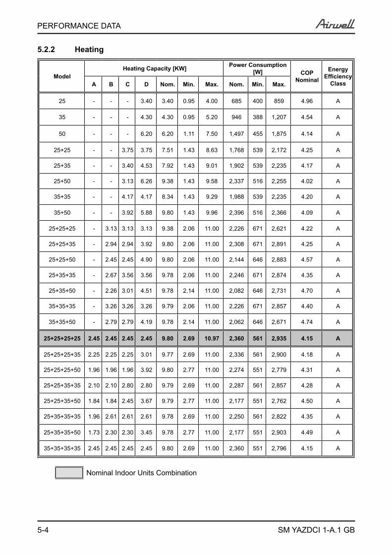
5.2.2 Heating
ModelHeating Capacity [KW] Power Consumption
[W] COPNominal
Energy Efficiency
ClassA B C D Nom. Min. Max. Nom. Min. Max.
25 - - - 3.40 3.40 0.95 4.00 685 400 859 4.96 A
35 - - - 4.30 4.30 0.95 5.20 946 388 1,207 4.54 A
50 - - - 6.20 6.20 1.11 7.50 1,497 455 1,875 4.14 A
25+25 - - 3.75 3.75 7.51 1.43 8.63 1,768 539 2,172 4.25 A
25+35 - - 3.40 4.53 7.92 1.43 9.01 1,902 539 2,235 4.17 A
25+50 - - 3.13 6.26 9.38 1.43 9.58 2,337 516 2,255 4.02 A
35+35 - - 4.17 4.17 8.34 1.43 9.29 1,988 539 2,235 4.20 A
35+50 - - 3.92 5.88 9.80 1.43 9.96 2,396 516 2,366 4.09 A
25+25+25 - 3.13 3.13 3.13 9.38 2.06 11.00 2,226 671 2,621 4.22 A
25+25+35 - 2.94 2.94 3.92 9.80 2.06 11.00 2,308 671 2,891 4.25 A
25+25+50 - 2.45 2.45 4.90 9.80 2.06 11.00 2,144 646 2,883 4.57 A
25+35+35 - 2.67 3.56 3.56 9.78 2.06 11.00 2,246 671 2,874 4.35 A
25+35+50 - 2.26 3.01 4.51 9.78 2.14 11.00 2,082 646 2,731 4.70 A
35+35+35 - 3.26 3.26 3.26 9.79 2.06 11.00 2,226 671 2,857 4.40 A
35+35+50 - 2.79 2.79 4.19 9.78 2.14 11.00 2,062 646 2,671 4.74 A
25+25+25+25 2.45 2.45 2.45 2.45 9.80 2.69 10.97 2,360 561 2,935 4.15 A
25+25+25+35 2.25 2.25 2.25 3.01 9.77 2.69 11.00 2,336 561 2,900 4.18 A
25+25+25+50 1.96 1.96 1.96 3.92 9.80 2.77 11.00 2,274 551 2,779 4.31 A
25+25+35+35 2.10 2.10 2.80 2.80 9.79 2.69 11.00 2,287 561 2,857 4.28 A
25+25+35+50 1.84 1.84 2.45 3.67 9.79 2.77 11.00 2,177 551 2,762 4.50 A
25+35+35+35 1.96 2.61 2.61 2.61 9.78 2.69 11.00 2,250 561 2,822 4.35 A
25+35+35+50 1.73 2.30 2.30 3.45 9.78 2.77 11.00 2,177 551 2,903 4.49 A
35+35+35+35 2.45 2.45 2.45 2.45 9.80 2.69 11.00 2,360 551 2,796 4.15 A
Nominal Indoor Units Combination
5-5
PERFORMANCE DATA
SM YAZDCI 1-A.1 GB
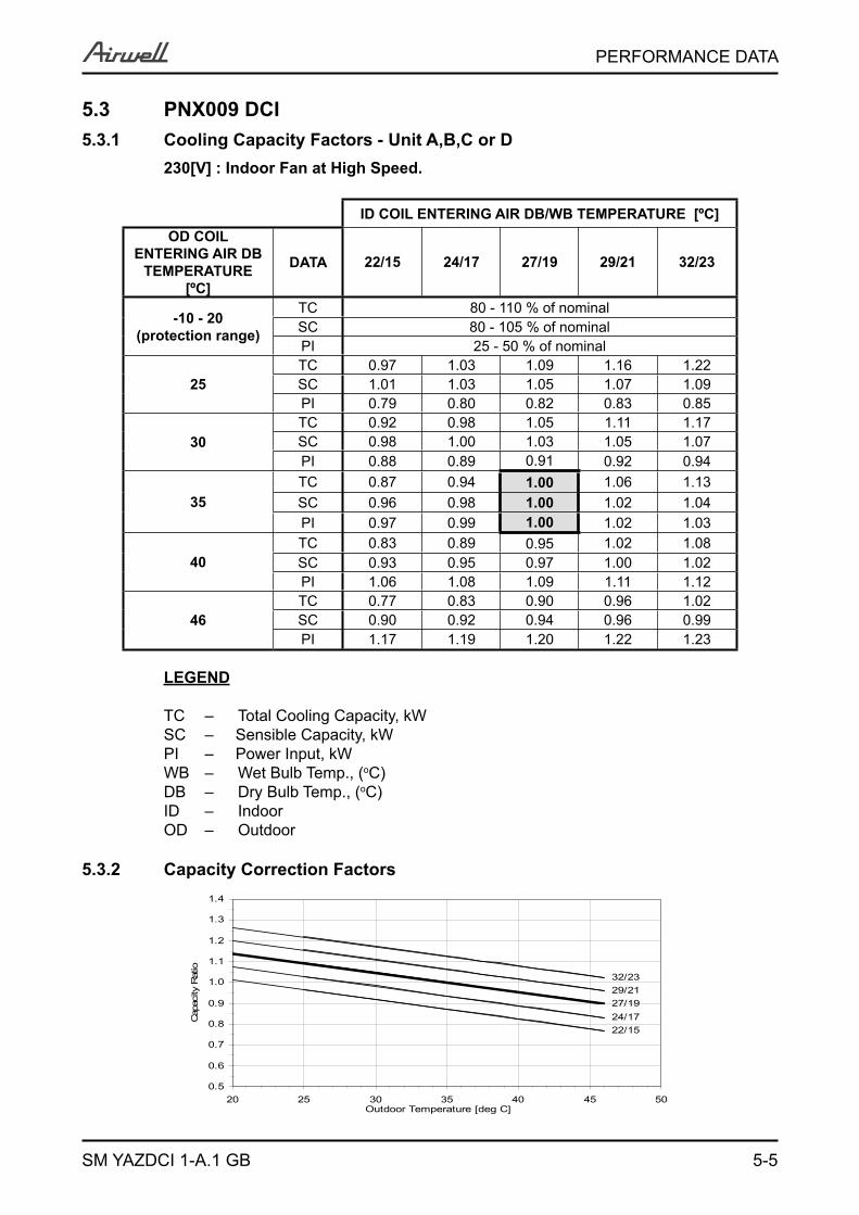
5.3 PNX009 DCI5.3.1 Cooling Capacity Factors - Unit A,B,C or D
230[V] : Indoor Fan at High Speed.
ID COIL ENTERING AIR DB/WB TEMPERATURE [ºC]OD COIL
ENTERING AIR DB TEMPERATURE
[ºC]
DATA 22/15 24/17 27/19 29/21 32/23
-10 - 20 (protection range)
TC 80 - 110 % of nominalSC 80 - 105 % of nominalPI 25 - 50 % of nominal
25TC 0.97 1.03 1.09 1.16 1.22SC 1.01 1.03 1.05 1.07 1.09PI 0.79 0.80 0.82 0.83 0.85
30TC 0.92 0.98 1.05 1.11 1.17SC 0.98 1.00 1.03 1.05 1.07PI 0.88 0.89 0.91 0.92 0.94
35TC 0.87 0.94 1.00 1.06 1.13SC 0.96 0.98 1.00 1.02 1.04PI 0.97 0.99 1.00 1.02 1.03
40TC 0.83 0.89 0.95 1.02 1.08SC 0.93 0.95 0.97 1.00 1.02PI 1.06 1.08 1.09 1.11 1.12
46TC 0.77 0.83 0.90 0.96 1.02SC 0.90 0.92 0.94 0.96 0.99PI 1.17 1.19 1.20 1.22 1.23
LEGEND
TC – Total Cooling Capacity, kWSC – Sensible Capacity, kWPI – Power Input, kWWB – Wet Bulb Temp., (oC)DB – Dry Bulb Temp., (oC)ID – IndoorOD – Outdoor
5.3.2 Capacity Correction Factors
27/19
22/1524/17
29/2132/23
0.5
0.6
0.7
0.8
0.9
1.0
1.1
1.2
1.3
1.4
20 25 30 35 40 45 50Outdoor Temperature [deg C]
Cap
acity
Rat
io
5-6
PERFORMANCE DATA
SM YAZDCI 1-A.1 GB
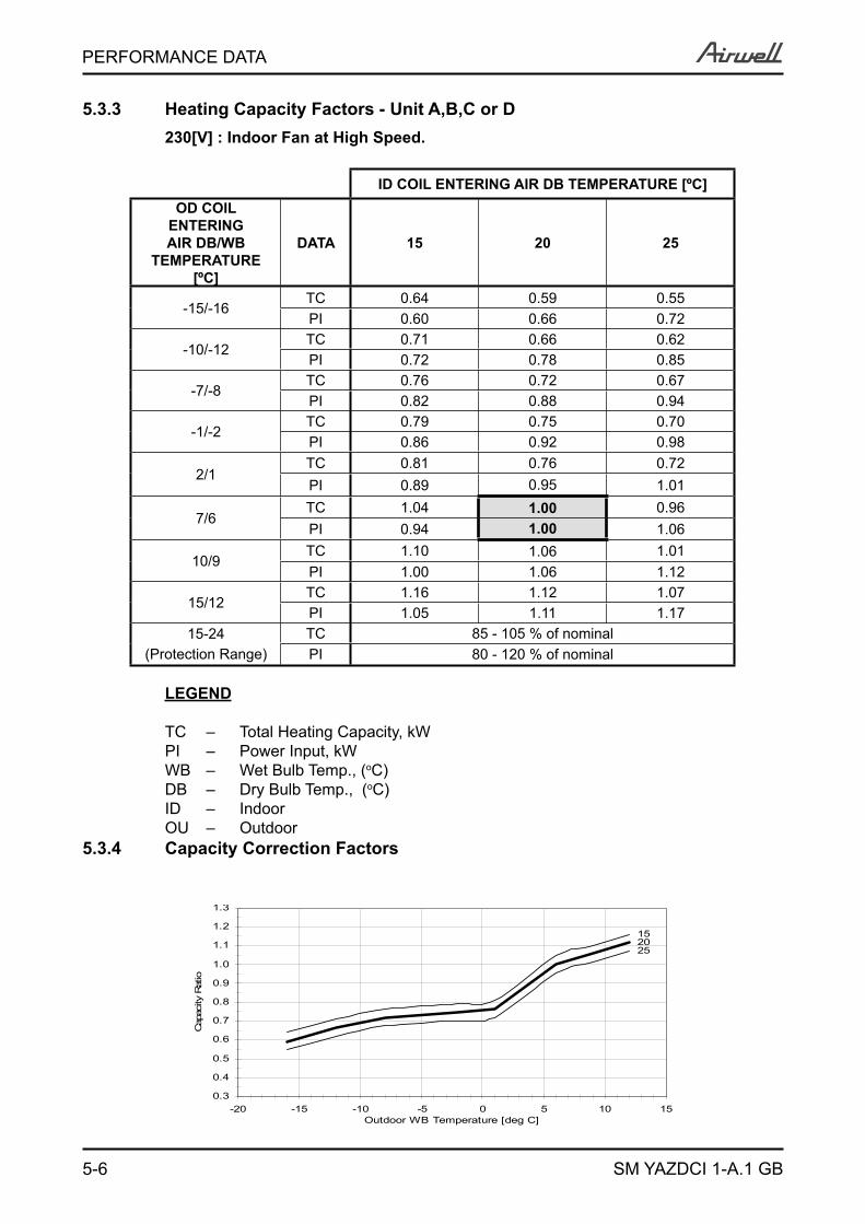
5.3.3 Heating Capacity Factors - Unit A,B,C or D230[V] : Indoor Fan at High Speed.
ID COIL ENTERING AIR DB TEMPERATURE [ºC]OD COIL
ENTERING AIR DB/WB
TEMPERATURE [ºC]
DATA 15 20 25
-15/-16TC 0.64 0.59 0.55PI 0.60 0.66 0.72
-10/-12TC 0.71 0.66 0.62PI 0.72 0.78 0.85
-7/-8TC 0.76 0.72 0.67PI 0.82 0.88 0.94
-1/-2TC 0.79 0.75 0.70PI 0.86 0.92 0.98
2/1TC 0.81 0.76 0.72PI 0.89 0.95 1.01
7/6TC 1.04 1.00 0.96PI 0.94 1.00 1.06
10/9TC 1.10 1.06 1.01PI 1.00 1.06 1.12
15/12TC 1.16 1.12 1.07PI 1.05 1.11 1.17
15-24 TC 85 - 105 % of nominal(Protection Range) PI 80 - 120 % of nominal
LEGEND
TC – Total Heating Capacity, kWPI – Power Input, kWWB – Wet Bulb Temp., (oC)DB – Dry Bulb Temp., (oC)ID – IndoorOU – Outdoor
5.3.4 Capacity Correction Factors
2025
15
0.3
0.4
0.5
0.6
0.7
0.8
0.9
1.0
1.1
1.2
1.3
-20 -15 -10 -5 0 5 10 15Outdoor WB Temperature [deg C]
Cap
acity
Rat
io
5-7
PERFORMANCE DATA
SM YAZDCI 1-A.1 GB
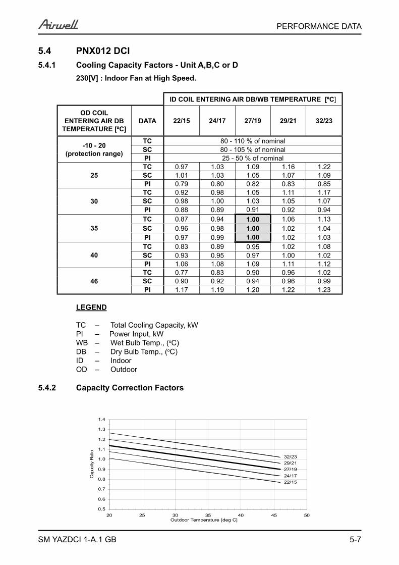
5.4 PNX012 DCI5.4.1 Cooling Capacity Factors - Unit A,B,C or D
230[V] : Indoor Fan at High Speed.
ID COIL ENTERING AIR DB/WB TEMPERATURE [ºC]
OD COIL ENTERING AIR DB
TEMPERATURE [ºC]DATA 22/15 24/17 27/19 29/21 32/23
-10 - 20 (protection range)
TC 80 - 110 % of nominalSC 80 - 105 % of nominalPI 25 - 50 % of nominal
25TC 0.97 1.03 1.09 1.16 1.22SC 1.01 1.03 1.05 1.07 1.09PI 0.79 0.80 0.82 0.83 0.85
30TC 0.92 0.98 1.05 1.11 1.17SC 0.98 1.00 1.03 1.05 1.07PI 0.88 0.89 0.91 0.92 0.94
35TC 0.87 0.94 1.00 1.06 1.13SC 0.96 0.98 1.00 1.02 1.04PI 0.97 0.99 1.00 1.02 1.03
40TC 0.83 0.89 0.95 1.02 1.08SC 0.93 0.95 0.97 1.00 1.02PI 1.06 1.08 1.09 1.11 1.12
46TC 0.77 0.83 0.90 0.96 1.02SC 0.90 0.92 0.94 0.96 0.99PI 1.17 1.19 1.20 1.22 1.23
LEGEND
TC – Total Cooling Capacity, kWPI – Power Input, kWWB – Wet Bulb Temp., (oC)DB – Dry Bulb Temp., (oC)ID – IndoorOD – Outdoor
5.4.2 Capacity Correction Factors
27/19
22/1524/17
29/2132/23
0.5
0.6
0.7
0.8
0.9
1.0
1.1
1.2
1.3
1.4
20 25 30 35 40 45 50Outdoor Temperature [deg C]
Cap
acity
Rat
io
5-8
PERFORMANCE DATA
SM YAZDCI 1-A.1 GB
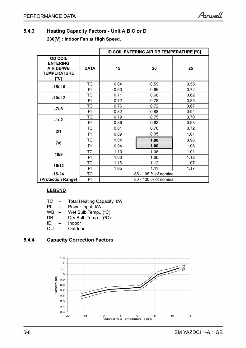
5.4.3 Heating Capacity Factors - Unit A,B,C or D230[V] : Indoor Fan at High Speed.
ID COIL ENTERING AIR DB TEMPERATURE [ºC]OD COIL
ENTERING AIR DB/WB
TEMPERATURE [ºC]
DATA 15 20 25
-15/-16 TC 0.64 0.59 0.55PI 0.60 0.66 0.72
-10/-12 TC 0.71 0.66 0.62PI 0.72 0.78 0.85
-7/-8 TC 0.76 0.72 0.67PI 0.82 0.88 0.94
-1/-2 TC 0.79 0.75 0.70PI 0.86 0.92 0.98
2/1TC 0.81 0.76 0.72PI 0.89 0.95 1.01
7/6TC 1.04 1.00 0.96PI 0.94 1.00 1.06
10/9 TC 1.10 1.06 1.01PI 1.00 1.06 1.12
15/12 TC 1.16 1.12 1.07PI 1.05 1.11 1.17
15-24 TC 85 - 105 % of nominal(Protection Range) PI 80 - 120 % of nominal
LEGEND
TC – Total Heating Capacity, kWPI – Power Input, kWWB – Wet Bulb Temp., (oC)DB – Dry Bulb Temp., (oC)ID – IndoorOU – Outdoor
5.4.4 Capacity Correction Factors
2025
15
0.3
0.4
0.5
0.6
0.7
0.8
0.9
1.0
1.1
1.2
1.3
-20 -15 -10 -5 0 5 10 15Outdoor WB Temperature [deg C]
Cap
acity
Rat
io
5-9
PERFORMANCE DATA
SM YAZDCI 1-A.1 GB
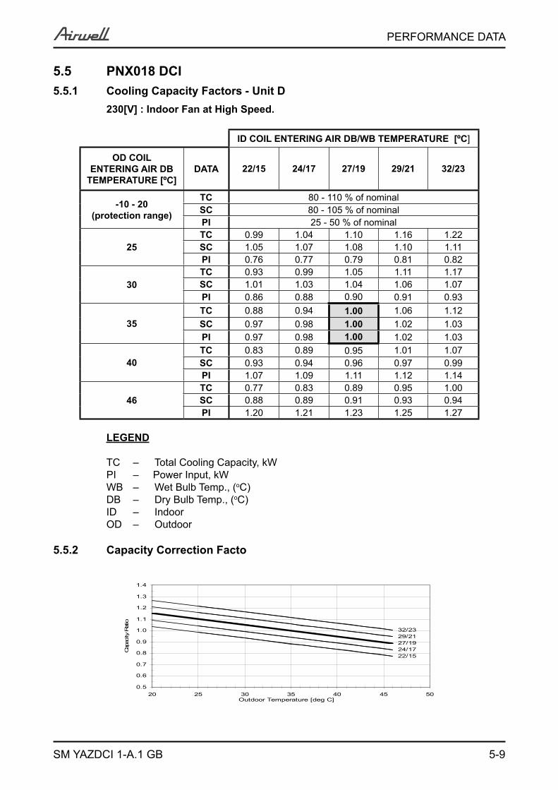
5.5 PNX018 DCI5.5.1 Cooling Capacity Factors - Unit D
230[V] : Indoor Fan at High Speed.
ID COIL ENTERING AIR DB/WB TEMPERATURE [ºC]
OD COIL ENTERING AIR DB
TEMPERATURE [ºC]DATA 22/15 24/17 27/19 29/21 32/23
-10 - 20 (protection range)
TC 80 - 110 % of nominalSC 80 - 105 % of nominalPI 25 - 50 % of nominal
25TC 0.99 1.04 1.10 1.16 1.22SC 1.05 1.07 1.08 1.10 1.11PI 0.76 0.77 0.79 0.81 0.82
30TC 0.93 0.99 1.05 1.11 1.17SC 1.01 1.03 1.04 1.06 1.07PI 0.86 0.88 0.90 0.91 0.93
35TC 0.88 0.94 1.00 1.06 1.12SC 0.97 0.98 1.00 1.02 1.03PI 0.97 0.98 1.00 1.02 1.03
40TC 0.83 0.89 0.95 1.01 1.07SC 0.93 0.94 0.96 0.97 0.99PI 1.07 1.09 1.11 1.12 1.14
46TC 0.77 0.83 0.89 0.95 1.00SC 0.88 0.89 0.91 0.93 0.94PI 1.20 1.21 1.23 1.25 1.27
LEGEND
TC – Total Cooling Capacity, kWPI – Power Input, kWWB – Wet Bulb Temp., (oC)DB – Dry Bulb Temp., (oC)ID – IndoorOD – Outdoor
5.5.2 Capacity Correction Facto
27/19
22/1524/17
29/2132/23
0.5
0.6
0.7
0.8
0.9
1.0
1.1
1.2
1.3
1.4
20 25 30 35 40 45 50Outdoor Temperature [deg C]
Cap
acity
Rat
io
5-10
PERFORMANCE DATA
SM YAZDCI 1-A.1 GB
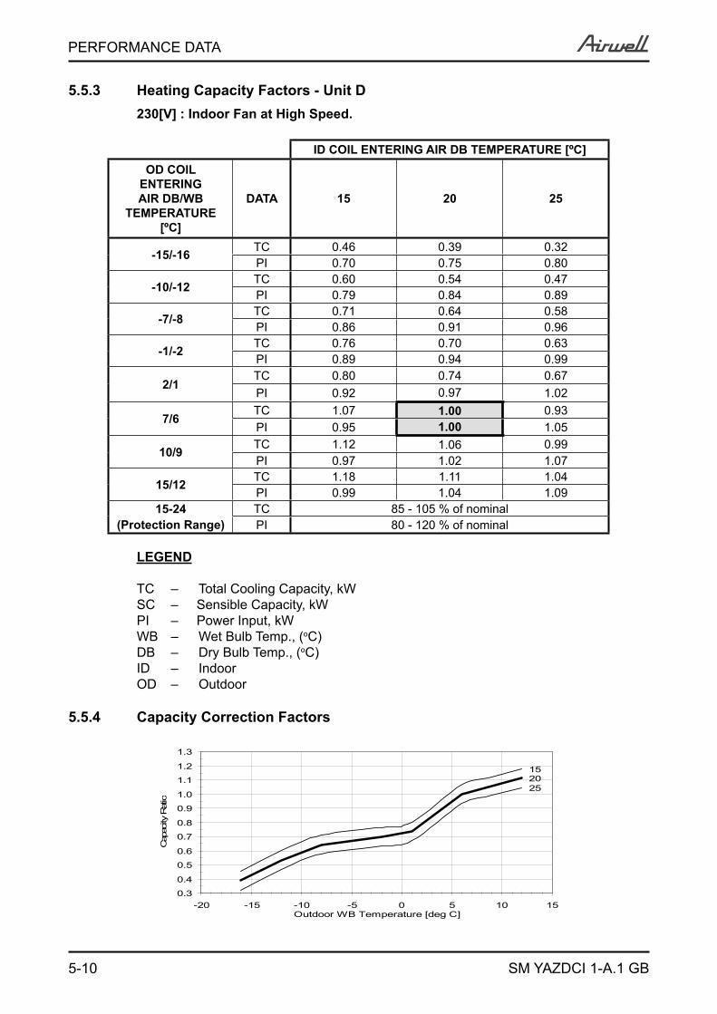
5.5.3 Heating Capacity Factors - Unit D230[V] : Indoor Fan at High Speed.
ID COIL ENTERING AIR DB TEMPERATURE [ºC]OD COIL
ENTERING AIR DB/WB
TEMPERATURE [ºC]
DATA 15 20 25
-15/-16 TC 0.46 0.39 0.32PI 0.70 0.75 0.80
-10/-12 TC 0.60 0.54 0.47PI 0.79 0.84 0.89
-7/-8 TC 0.71 0.64 0.58PI 0.86 0.91 0.96
-1/-2 TC 0.76 0.70 0.63PI 0.89 0.94 0.99
2/1TC 0.80 0.74 0.67PI 0.92 0.97 1.02
7/6TC 1.07 1.00 0.93PI 0.95 1.00 1.05
10/9 TC 1.12 1.06 0.99PI 0.97 1.02 1.07
15/12 TC 1.18 1.11 1.04PI 0.99 1.04 1.09
15-24 TC 85 - 105 % of nominal(Protection Range) PI 80 - 120 % of nominal
LEGEND
TC – Total Cooling Capacity, kWSC – Sensible Capacity, kWPI – Power Input, kWWB – Wet Bulb Temp., (oC)DB – Dry Bulb Temp., (oC)ID – IndoorOD – Outdoor
5.5.4 Capacity Correction Factors
2025
15
0.3
0.4
0.5
0.6
0.7
0.8
0.9
1.0
1.1
1.2
1.3
-20 -15 -10 -5 0 5 10 15Outdoor WB Temperature [deg C]
Cap
acity
Rat
io
5-11
PERFORMANCE DATA
SM YAZDCI 1-A.1 GB
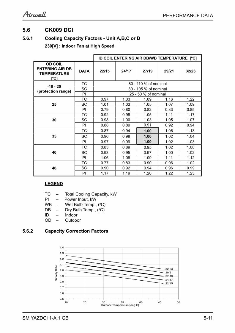
5.6 CK009 DCI 5.6.1 Cooling Capacity Factors - Unit A,B,C or D
230[V] : Indoor Fan at High Speed.
ID COIL ENTERING AIR DB/WB TEMPERATURE [ºC]OD COIL
ENTERING AIR DB TEMPERATURE
[ºC]
DATA 22/15 24/17 27/19 29/21 32/23
-10 - 20 (protection range)
TC 80 - 110 % of nominalSC 80 - 105 % of nominalPI 25 - 50 % of nominal
25TC 0.97 1.03 1.09 1.16 1.22SC 1.01 1.03 1.05 1.07 1.09PI 0.79 0.80 0.82 0.83 0.85
30TC 0.92 0.98 1.05 1.11 1.17SC 0.98 1.00 1.03 1.05 1.07PI 0.88 0.89 0.91 0.92 0.94
35TC 0.87 0.94 1.00 1.06 1.13SC 0.96 0.98 1.00 1.02 1.04PI 0.97 0.99 1.00 1.02 1.03
40TC 0.83 0.89 0.95 1.02 1.08SC 0.93 0.95 0.97 1.00 1.02PI 1.06 1.08 1.09 1.11 1.12
46TC 0.77 0.83 0.90 0.96 1.02SC 0.90 0.92 0.94 0.96 0.99PI 1.17 1.19 1.20 1.22 1.23
LEGEND
TC – Total Cooling Capacity, kWPI – Power Input, kWWB – Wet Bulb Temp., (oC)DB – Dry Bulb Temp., (oC)ID – IndoorOD – Outdoor
5.6.2 Capacity Correction Factors
27/19
22/1524/17
29/2132/23
0.5
0.6
0.7
0.8
0.9
1.0
1.1
1.2
1.3
1.4
20 25 30 35 40 45 50Outdoor Temperature [deg C]
Cap
acity
Rat
io
5-12
PERFORMANCE DATA
SM YAZDCI 1-A.1 GB
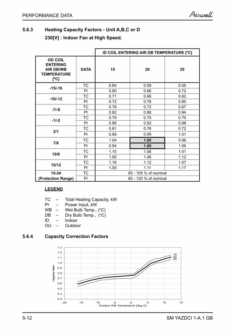
5.6.3 Heating Capacity Factors - Unit A,B,C or D 230[V] : Indoor Fan at High Speed.
ID COIL ENTERING AIR DB TEMPERATURE [ºC]
OD COIL ENTERING AIR DB/WB
TEMPERATURE [ºC]
DATA 15 20 25
-15/-16 TC 0.64 0.59 0.55PI 0.60 0.66 0.72
-10/-12 TC 0.71 0.66 0.62PI 0.72 0.78 0.85
-7/-8 TC 0.76 0.72 0.67PI 0.82 0.88 0.94
-1/-2 TC 0.79 0.75 0.70PI 0.86 0.92 0.98
2/1TC 0.81 0.76 0.72PI 0.89 0.95 1.01
7/6TC 1.04 1.00 0.96PI 0.94 1.00 1.06
10/9 TC 1.10 1.06 1.01PI 1.00 1.06 1.12
15/12 TC 1.16 1.12 1.07PI 1.05 1.11 1.17
15-24 TC 85 - 105 % of nominal(Protection Range) PI 80 - 120 % of nominal
LEGEND
TC – Total Heating Capacity, kWPI – Power Input, kWWB – Wet Bulb Temp., (oC)DB – Dry Bulb Temp., (oC)ID – IndoorOU – Outdoor
5.6.4 Capacity Correction Factors
2025
15
0.3
0.4
0.5
0.6
0.7
0.8
0.9
1.0
1.1
1.2
1.3
-20 -15 -10 -5 0 5 10 15Outdoor WB Temperature [deg C]
Cap
acity
Rat
io
5-13
PERFORMANCE DATA
SM YAZDCI 1-A.1 GB
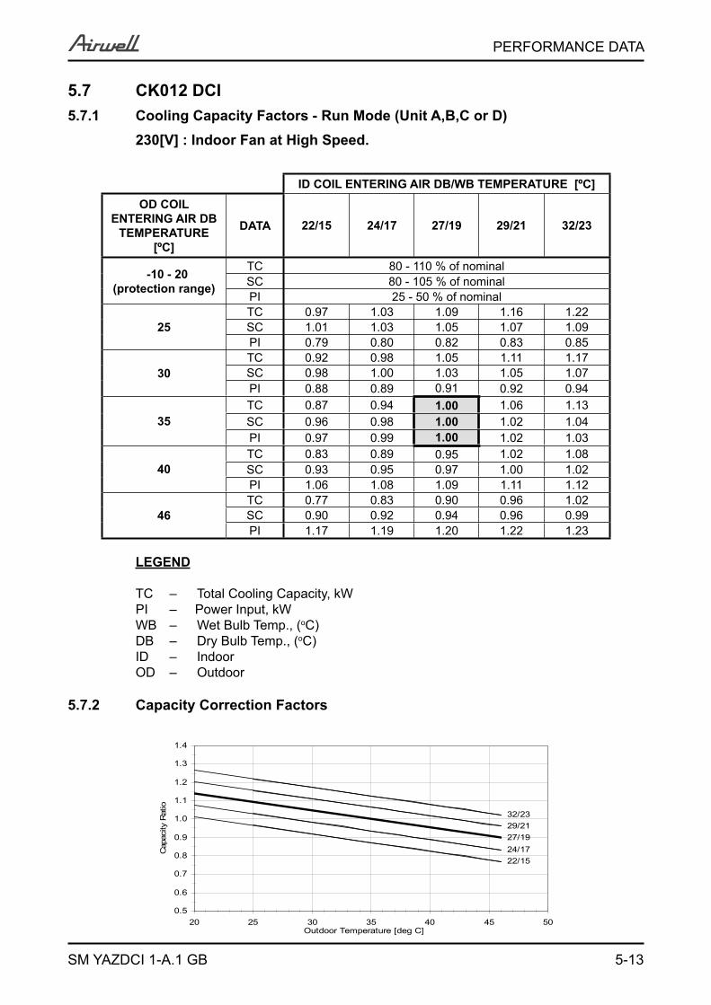
5.7 CK012 DCI 5.7.1 Cooling Capacity Factors - Run Mode (Unit A,B,C or D) 230[V] : Indoor Fan at High Speed.
ID COIL ENTERING AIR DB/WB TEMPERATURE [ºC]OD COIL
ENTERING AIR DB TEMPERATURE
[ºC]
DATA 22/15 24/17 27/19 29/21 32/23
-10 - 20 (protection range)
TC 80 - 110 % of nominalSC 80 - 105 % of nominalPI 25 - 50 % of nominal
25TC 0.97 1.03 1.09 1.16 1.22SC 1.01 1.03 1.05 1.07 1.09PI 0.79 0.80 0.82 0.83 0.85
30TC 0.92 0.98 1.05 1.11 1.17SC 0.98 1.00 1.03 1.05 1.07PI 0.88 0.89 0.91 0.92 0.94
35TC 0.87 0.94 1.00 1.06 1.13SC 0.96 0.98 1.00 1.02 1.04PI 0.97 0.99 1.00 1.02 1.03
40TC 0.83 0.89 0.95 1.02 1.08SC 0.93 0.95 0.97 1.00 1.02PI 1.06 1.08 1.09 1.11 1.12
46TC 0.77 0.83 0.90 0.96 1.02SC 0.90 0.92 0.94 0.96 0.99PI 1.17 1.19 1.20 1.22 1.23
LEGEND
TC – Total Cooling Capacity, kWPI – Power Input, kWWB – Wet Bulb Temp., (oC)DB – Dry Bulb Temp., (oC)ID – IndoorOD – Outdoor
5.7.2 Capacity Correction Factors
27/19
22/1524/17
29/2132/23
0.5
0.6
0.7
0.8
0.9
1.0
1.1
1.2
1.3
1.4
20 25 30 35 40 45 50Outdoor Temperature [deg C]
Cap
acity
Rat
io
5-14
PERFORMANCE DATA
SM YAZDCI 1-A.1 GB
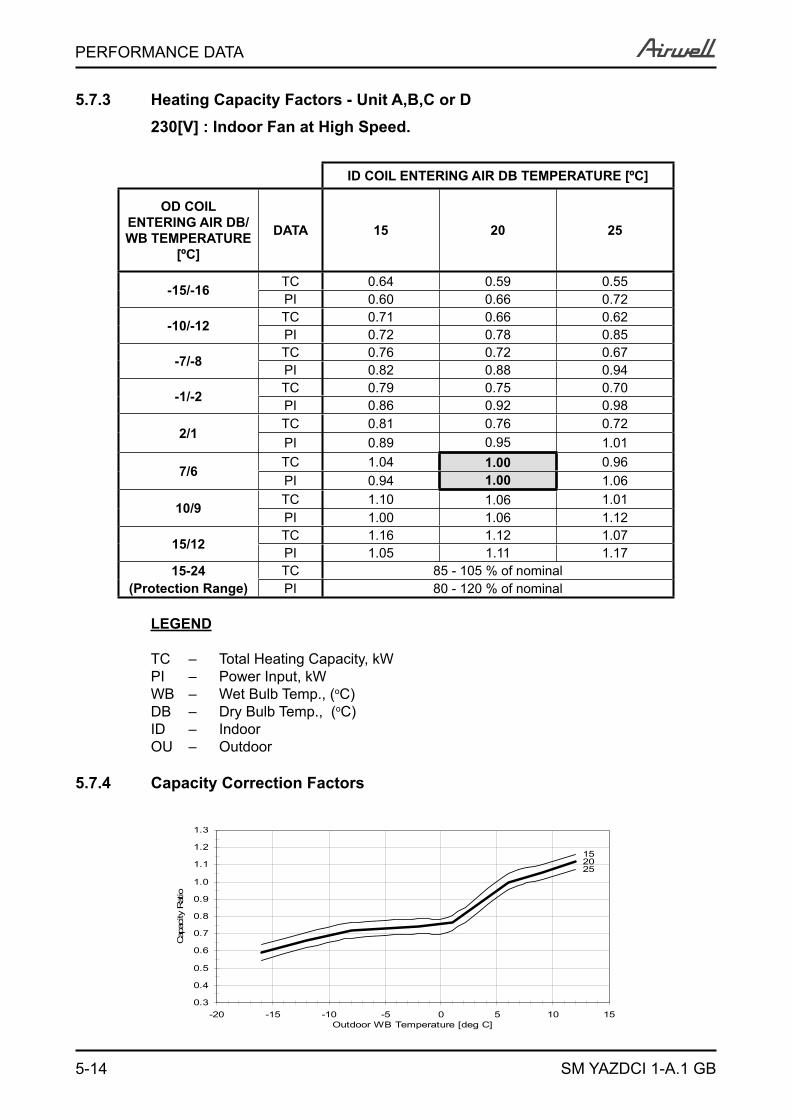
5.7.3 Heating Capacity Factors - Unit A,B,C or D 230[V] : Indoor Fan at High Speed.
ID COIL ENTERING AIR DB TEMPERATURE [ºC]
OD COIL ENTERING AIR DB/WB TEMPERATURE
[ºC]
DATA 15 20 25
-15/-16 TC 0.64 0.59 0.55PI 0.60 0.66 0.72
-10/-12 TC 0.71 0.66 0.62PI 0.72 0.78 0.85
-7/-8 TC 0.76 0.72 0.67PI 0.82 0.88 0.94
-1/-2 TC 0.79 0.75 0.70PI 0.86 0.92 0.98
2/1TC 0.81 0.76 0.72PI 0.89 0.95 1.01
7/6TC 1.04 1.00 0.96PI 0.94 1.00 1.06
10/9 TC 1.10 1.06 1.01PI 1.00 1.06 1.12
15/12 TC 1.16 1.12 1.07PI 1.05 1.11 1.17
15-24 TC 85 - 105 % of nominal(Protection Range) PI 80 - 120 % of nominal
LEGEND
TC – Total Heating Capacity, kWPI – Power Input, kWWB – Wet Bulb Temp., (oC)DB – Dry Bulb Temp., (oC)ID – IndoorOU – Outdoor
5.7.4 Capacity Correction Factors
2025
15
0.3
0.4
0.5
0.6
0.7
0.8
0.9
1.0
1.1
1.2
1.3
-20 -15 -10 -5 0 5 10 15Outdoor WB Temperature [deg C]
Cap
acity
Rat
io
5-15
PERFORMANCE DATA
SM YAZDCI 1-A.1 GB
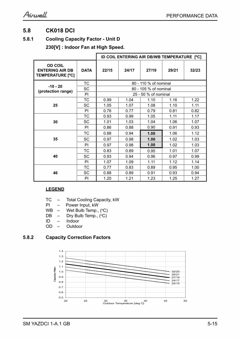
5.8 CK018 DCI 5.8.1 Cooling Capacity Factor - Unit D 230[V] : Indoor Fan at High Speed.
ID COIL ENTERING AIR DB/WB TEMPERATURE [ºC]
OD COIL ENTERING AIR DB
TEMPERATURE [ºC]DATA 22/15 24/17 27/19 29/21 32/23
-10 - 20 (protection range)
TC 80 - 110 % of nominalSC 80 - 105 % of nominalPI 25 - 50 % of nominal
25TC 0.99 1.04 1.10 1.16 1.22SC 1.05 1.07 1.08 1.10 1.11PI 0.76 0.77 0.79 0.81 0.82
30TC 0.93 0.99 1.05 1.11 1.17SC 1.01 1.03 1.04 1.06 1.07PI 0.86 0.88 0.90 0.91 0.93
35TC 0.88 0.94 1.00 1.06 1.12SC 0.97 0.98 1.00 1.02 1.03PI 0.97 0.98 1.00 1.02 1.03
40TC 0.83 0.89 0.95 1.01 1.07SC 0.93 0.94 0.96 0.97 0.99PI 1.07 1.09 1.11 1.12 1.14
46TC 0.77 0.83 0.89 0.95 1.00SC 0.88 0.89 0.91 0.93 0.94PI 1.20 1.21 1.23 1.25 1.27
LEGEND
TC – Total Cooling Capacity, kWPI – Power Input, kWWB – Wet Bulb Temp., (oC)DB – Dry Bulb Temp., (oC)ID – IndoorOD – Outdoor
5.8.2 Capacity Correction Factors
27/19
22/1524/17
29/2132/23
0.5
0.6
0.7
0.8
0.9
1.0
1.1
1.2
1.3
1.4
20 25 30 35 40 45 50Outdoor Temperature [deg C]
Cap
acity
Rat
io
5-16
PERFORMANCE DATA
SM YAZDCI 1-A.1 GB
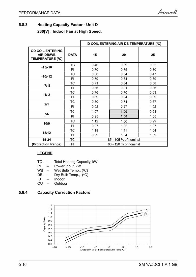
5.8.3 Heating Capacity Factor - Unit D 230[V] : Indoor Fan at High Speed.
ID COIL ENTERING AIR DB TEMPERATURE [ºC]
OD COIL ENTERING AIR DB/WB
TEMPERATURE [ºC]DATA 15 20 25
-15/-16TC 0.46 0.39 0.32PI 0.70 0.75 0.80
-10/-12TC 0.60 0.54 0.47PI 0.79 0.84 0.89
-7/-8TC 0.71 0.64 0.58PI 0.86 0.91 0.96
-1/-2TC 0.76 0.70 0.63PI 0.89 0.94 0.99
2/1TC 0.80 0.74 0.67PI 0.92 0.97 1.02
7/6TC 1.07 1.00 0.93PI 0.95 1.00 1.05
10/9TC 1.12 1.06 0.99PI 0.97 1.02 1.07
15/12TC 1.18 1.11 1.04PI 0.99 1.04 1.09
15-24 TC 85 - 105 % of nominal(Protection Range) PI 80 - 120 % of nominal
LEGEND
TC – Total Heating Capacity, kWPI – Power Input, kWWB – Wet Bulb Temp., (oC)DB – Dry Bulb Temp., (oC)ID – IndoorOU – Outdoor
5.8.4 Capacity Correction Factors
2025
15
0.3
0.4
0.5
0.6
0.7
0.8
0.9
1.0
1.1
1.2
1.3
-20 -15 -10 -5 0 5 10 15Outdoor WB Temperature [deg C]
Cap
acity
Rat
io
5-17
PERFORMANCE DATA
SM YAZDCI 1-A.1 GB
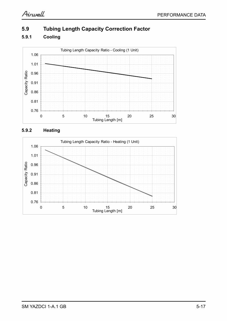
Tubing Length Capacity Ratio - Cooling (1 Unit)
0.76
0.81
0.86
0.91
0.96
1.01
1.06
0 5 10 15 20 25 30Tubing Length [m]
Cap
acity
Rat
io
Tubing Length Capacity Ratio - Heating (1 Unit)
0.76
0.81
0.86
0.91
0.96
1.01
1.06
0 5 10 15 20 25 30Tubing Length [m]
Cap
acity
Rat
io5.9 Tubing Length Capacity Correction Factor 5.9.1 Cooling
5.9.2 Heating
5-18
PERFORMANCE DATA
SM YAZDCI 1-A.1 GB
5.10 Model Correction Factors (FM)
ModelCapacity Power input
Cooling Heating Cooling HeatingPNX DCI 1.00 1.00 1.00 1.00CK DCI 1.03 1.07 1.01 1.10SX DCIDLF DCIXL DCIDLS DCIPRIME DCIHAD DCI
15.11 Calculation Example
Outdoor Unit YAZ4 30 DCIIndoor Combination PNX009+PNX012+CK012+PNX018Operation Mode Cooling ModeConditions Indoor 22CDB/15WBConditions Oudoor 30CDB Tubing length 20m+10m+5m+25m
Cooling Capacity calculation:CA-D [KW] = Nominal x FM x FC x FT Total System Capacity [KW] (TC) = CA + CB + CC + CD
Indoor UnitNom’ Cooling
Capacity[KW]
Model Factor
(FM)
Condition Factor
(FC)
Tubing(L) Factor
(FT)
Corrected Capacity[KW], (CA-D)
Room A – PNX009 1.43 1.00 0.92 0.95 CA = 1.43x1.00x0.92x0.95=1.25Room B – PNX012 1.91 1.00 0.92 0.985 CB = 1.91x1.00x0.92x0.985=1.73Room C – CK012 1.91 1.03 0.92 1.00 CC = 1.91x1.03x0.92x1.00=1.81Room D – PNX018 2.87 1.00 0.93 0.93 CD = 2.87x1.00x0.93x0.93=2.48
Total TC =1.25+1.73+1.81+2.48=7.27
Cooling Power Input calculation:PA-D [KW] = Nominal x FM x FC x FT Total System Power Input [W] (TP) = PA + PB + PC + PD
Indoor UnitNom’ Cooling Power Input
[W]
Model Factor
(FM)
Condition Factor
(FC)
Corrected Power Input [W](PA-D)
Room A – PNX009
2,410 / 4 = 602.5
1.00 0.88 PA = 602.5 x 1.00 x 0.88 = 530Room B – PNX012 1.00 0.88 PB = 602.5 x 1.00 x 0.88 = 530Room C – CK012 1.01 0.88 PC = 602.5 x 1.01 x 0.88 = 535Room D – PNX018 1.00 0.86 PD = 602.5 x 1.00 x 0.86 = 518
Total TP = 530 + 530 + 535 + 518 = 2,113

6-1
PRESSURE CURVES
SM YAZDCI 1-A.1 GB
6. PRESSURE CURVES6.1 Model: YAZ3 24 DCI6.1.1 Cooling – Technician Mode
Discharge Pressure - Cooling (Technician Mode)(WNG25+25+25 ; 5m each)
15.0
20.0
25.0
30.0
35.0
40.0
10 15 20 25 30 35 40 45Outdoor DB Temperature [ºC]
Bar(g)
32/2329/2127/1924/1722/15
Suction Pressure - Cooling (Technician Mode) (WNG25+25+25 ; 5m each)
6.00
7.00
8.00
9.00
10.00
11.00
12.00
10 15 20 25 30 35 40 45
Outdoor DB Temperature [ºC]
Bar(g)
32/2329/2127/1924/1722/15
6-2
PRESSURE CURVES
SM YAZDCI 1-A.1 GB
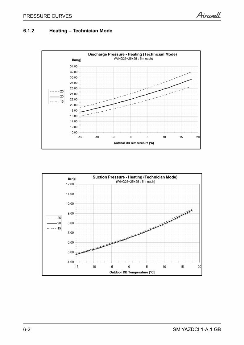
6.1.2 Heating – Technician Mode
Discharge Pressure - Heating (Technician Mode)(WNG25+25+25 ; 5m each)
10.00
12.00
14.00
16.00
18.00
20.00
22.00
24.00
26.00
28.00
30.00
32.00
34.00
-15 -10 -5 0 5 10 15 20
Outdoor DB Temperature [ºC]
Bar(g)
252015
Suction Pressure - Heating (Technician Mode)(WNG25+25+25 ; 5m each)
4.00
5.00
6.00
7.00
8.00
9.00
10.00
11.00
12.00
-15 -10 -5 0 5 10 15 20
Outdoor DB Temperature [ºC]
Bar(g)
252015
6-3
PRESSURE CURVES
SM YAZDCI 1-A.1 GB
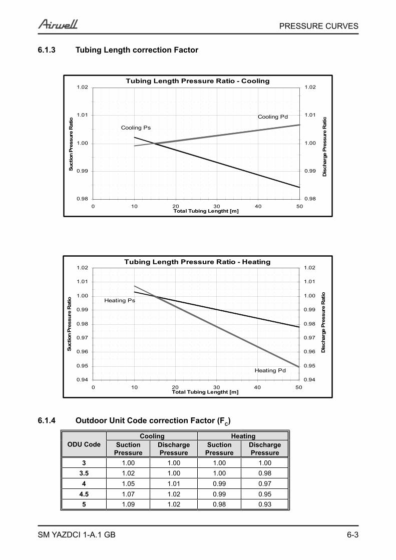
6.1.3 Tubing Length correction Factor
6.1.4 Outdoor Unit Code correction Factor (FC)
ODU CodeCooling Heating
Suction Pressure
Discharge Pressure
Suction Pressure
Discharge Pressure
3 1.00 1.00 1.00 1.003.5 1.02 1.00 1.00 0.984 1.05 1.01 0.99 0.97
4.5 1.07 1.02 0.99 0.955 1.09 1.02 0.98 0.93
Tubing Length Pressure Ratio - Cooling
Cooling Ps
Cooling Pd
0.98
0.99
1.00
1.01
1.02
0 10 20 30 40 50Total Tubing Lengtht [m]
Suct
ion
Pres
sure
Rat
io
0.98
0.99
1.00
1.01
1.02
Dis
char
ge P
ress
ure
Rat
io
Tubing Length Pressure Ratio - Heating
Heating Ps
Heating Pd
0.94
0.95
0.96
0.97
0.98
0.99
1.00
1.01
1.02
0 10 20 30 40 50Total Tubing Lengtht [m]
Suct
ion
Pres
sure
Rat
io
0.94
0.95
0.96
0.97
0.98
0.99
1.00
1.01
1.02
Dis
char
ge P
ress
ure
Rat
io

6-4
PRESSURE CURVES
SM YAZDCI 1-A.1 GB
6.1.5 Unit Model correction Factor (Fm)
Model
Cooling Heating
SuctionPressure
DischargePressure
SuctionPressure
DischargePressure
PNX009 DCI 1.00 1.00 1.00 1.00PNX012 DCI 1.00 1.00 1.00 1.00PNX018 DCI 1.00 1.00 1.00 1.00CK009 DCI 1.01 1.00 1.02 1.17CK012 DCI 1.08 1.02 1.01 1.11CK018 DCI 0.87 1.00 1.00 0.69SX009 DCISX012 DCISX018 DCIDLF009 DCIDLF012 DCIDLF018 DCIXLF009 DCIXLF012 DCIDLS018 DCIPRIME009 DCIPRIME012 DCIPRIME018 DCIHAD009 DCIHAD012 DCI
6-5
PRESSURE CURVES
SM YAZDCI 1-A.1 GB
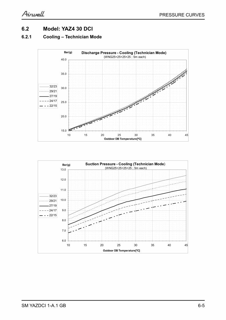
6.2 Model: YAZ4 30 DCI6.2.1 Cooling – Technician Mode
Discharge Pressure - Cooling (Technician Mode)(WNG25+25+25+25 ; 5m each)
15.0
20.0
25.0
30.0
35.0
40.0
10 15 20 25 30 35 40 45Outdoor DB Temperature[ºC]
Bar(g)
32/2329/2127/1924/1722/15
Suction Pressure - Cooling (Technician Mode)(WNG25+25+25+25 ; 5m each)
6.0
7.0
8.0
9.0
10.0
11.0
12.0
13.0
10 15 20 25 30 35 40 45
Outdoor DB Temperature[ºC]
Bar(g)
32/2329/2127/1924/1722/15
6-6
PRESSURE CURVES
SM YAZDCI 1-A.1 GB
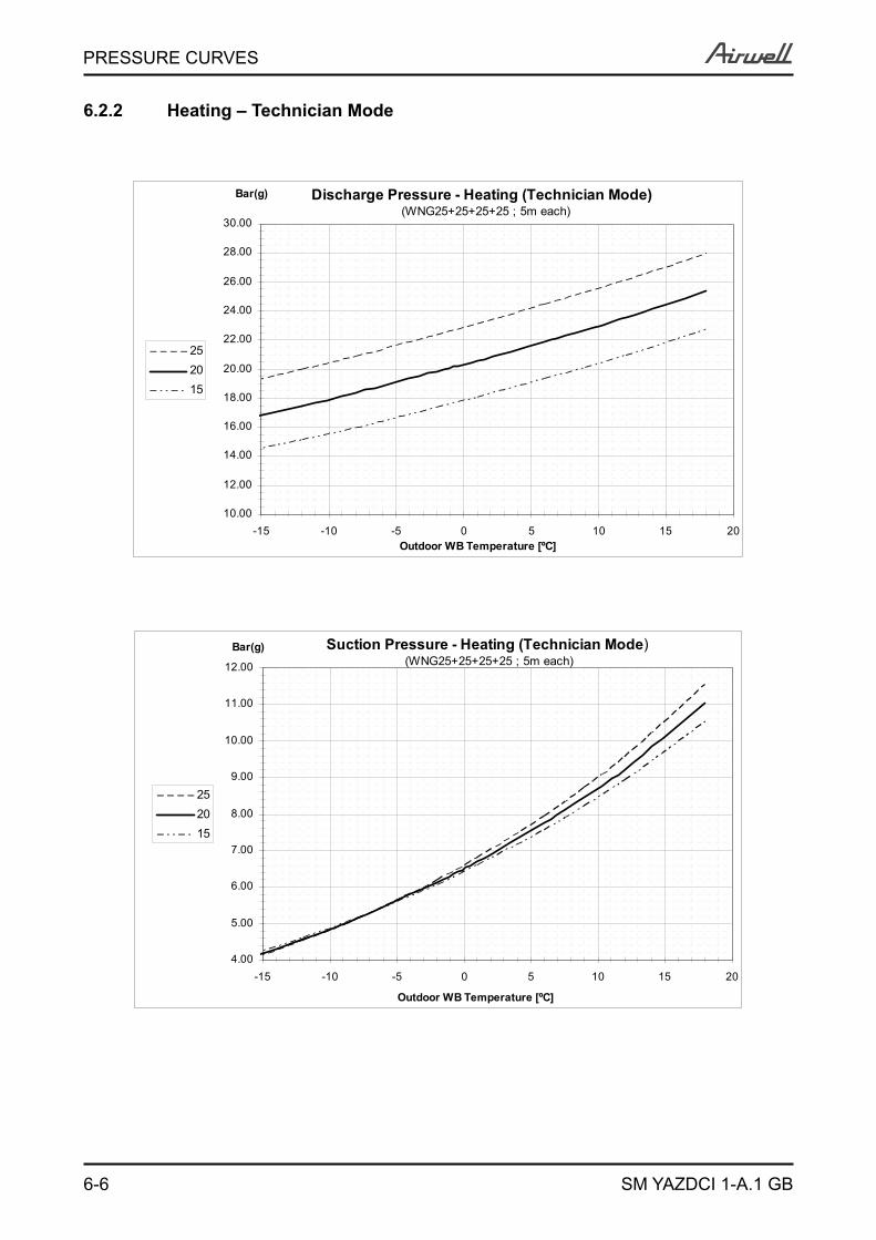
6.2.2 Heating – Technician Mode
Discharge Pressure - Heating (Technician Mode) (WNG25+25+25+25 ; 5m each)
10.00
12.00
14.00
16.00
18.00
20.00
22.00
24.00
26.00
28.00
30.00
-15 -10 -5 0 5 10 15 20Outdoor WB Temperature [ºC]
Bar(g)
252015
Suction Pressure - Heating (Technician Mode)(WNG25+25+25+25 ; 5m each)
4.00
5.00
6.00
7.00
8.00
9.00
10.00
11.00
12.00
-15 -10 -5 0 5 10 15 20
Outdoor WB Temperature [ºC]
Bar(g)
252015
6-7
PRESSURE CURVES
SM YAZDCI 1-A.1 GB
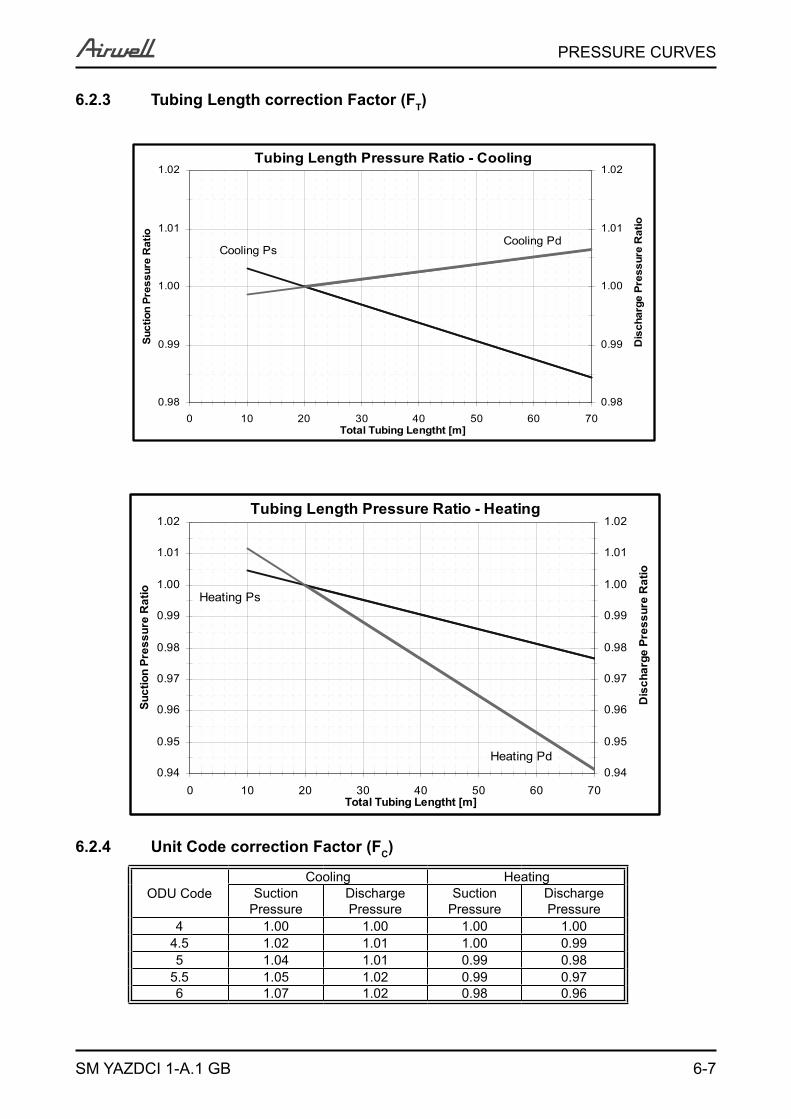
6.2.3 Tubing Length correction Factor (FT)
6.2.4 Unit Code correction Factor (FC)
ODU CodeCooling Heating
SuctionPressure
DischargePressure
SuctionPressure
DischargePressure
4 1.00 1.00 1.00 1.004.5 1.02 1.01 1.00 0.995 1.04 1.01 0.99 0.98
5.5 1.05 1.02 0.99 0.976 1.07 1.02 0.98 0.96
Tubing Length Pressure Ratio - Cooling
Cooling PsCooling Pd
0.98
0.99
1.00
1.01
1.02
0 10 20 30 40 50 60 70Total Tubing Lengtht [m]
Suct
ion
Pres
sure
Rat
io
0.98
0.99
1.00
1.01
1.02
Dis
char
ge P
ress
ure
Rat
io
Tubing Length Pressure Ratio - Heating
Heating Ps
Heating Pd0.94
0.95
0.96
0.97
0.98
0.99
1.00
1.01
1.02
0 10 20 30 40 50 60 70Total Tubing Lengtht [m]
Suct
ion
Pres
sure
Rat
io
0.94
0.95
0.96
0.97
0.98
0.99
1.00
1.01
1.02
Dis
char
ge P
ress
ure
Rat
io
6-8
PRESSURE CURVES
SM YAZDCI 1-A.1 GB
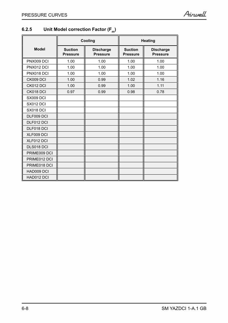
6.2.5 Unit Model correction Factor (Fm)
Model
Cooling Heating
Suction Pressure
Discharge Pressure
Suction Pressure
Discharge Pressure
PNX009 DCI 1.00 1.00 1.00 1.00PNX012 DCI 1.00 1.00 1.00 1.00PNX018 DCI 1.00 1.00 1.00 1.00CK009 DCI 1.00 0.99 1.02 1.16CK012 DCI 1.00 0.99 1.00 1.11CK018 DCI 0.97 0.99 0.98 0.78SX009 DCISX012 DCISX018 DCIDLF009 DCIDLF012 DCIDLF018 DCIXLF009 DCIXLF012 DCIDLS018 DCIPRIME009 DCIPRIME012 DCIPRIME018 DCIHAD009 DCIHAD012 DCI

6-9
PRESSURE CURVES
SM YAZDCI 1-A.1 GB
6.3 Calculation Example
Outdoor Unit YAZ4 30 DCI
Indoor Combination PNX009+PNX012+CK012+PNX018
Operation Mode Cooling Mode
Conditions Indoor 22CDB/15WB
Conditions Oudoor 30CDB
Tubing length 20m+10m+5m+25m = 60m
Cooling Pressure calculation:Pressure [Barg] = Nominal x FC x FT
Unit CodeRoom A – PNX009 1.0Room B – PNX012 1.5Room C – CK012 1.5Room D – PNX018 2.0ODU Code (Total) 6.0
Nominal Pressure [Barg]
ODU Code Factor(FC)
Tubing (L) Factor(FT)
Corrected Pressure [Barg]
Discharge 24.5 1.02 1.005 Pd= 24.5 x 1.02 x 1.005 = 25.11Suction 9.0 1.07 0.988 Ps= 9.0 x 1.07 x 0.988 = 9.51
7-1
ELECTRICAL DATA
SM YAZDCI 1-A.1 GB
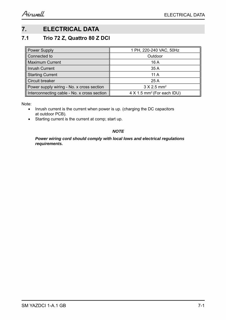
7. ELECTRICAL DATA7.1 Trio 72 Z, Quattro 80 Z DCI
Power Supply 1 PH, 220-240 VAC, 50HzConnected to OutdoorMaximum Current 16 AInrush Current 35 AStarting Current 11 ACircuit breaker 25 APower supply wiring - No. x cross section 3 X 2.5 mm2
Interconnecting cable - No. x cross section 4 X 1.5 mm2 (For each IDU)
Note: Inrush current is the current when power is up. (charging the DC capacitors at outdoor PCB). Starting current is the current at comp; start up.
NOTE
Power wiring cord should comply with local lows and electrical regulations requirements.
8-1
WIRING DIAGRAMS & ELECTRICAL CONNECTIONS
SM YAZDCI 1-A.1 GB
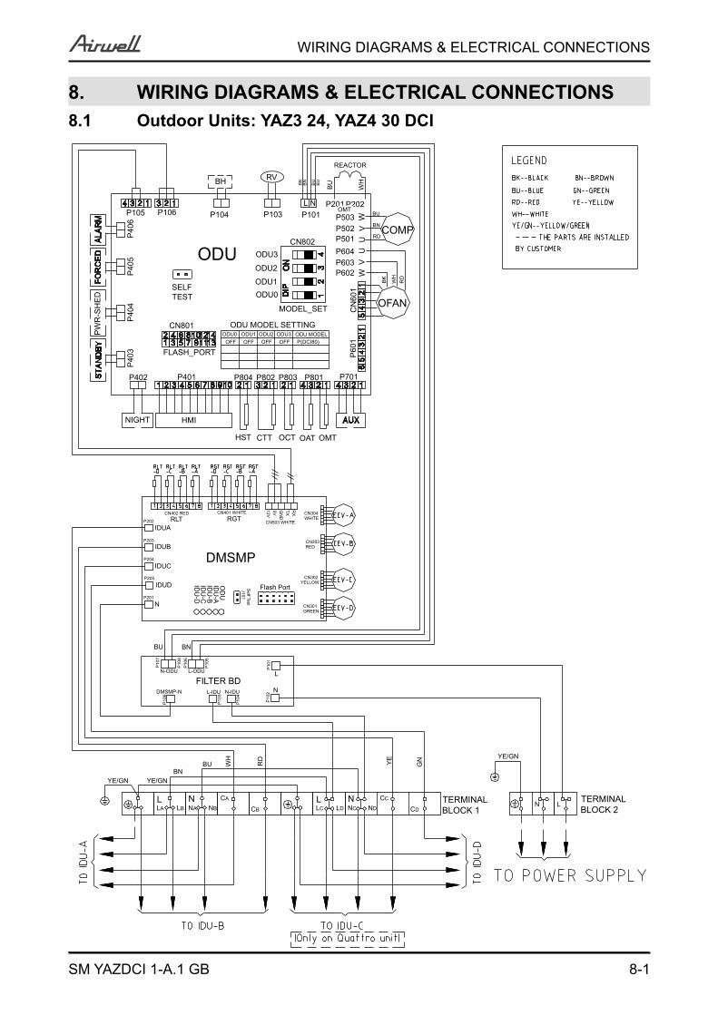
8. WIRING DIAGRAMS & ELECTRICAL CONNECTIONS8.1 Outdoor Units: YAZ3 24, YAZ4 30 DCI
P10
1
P10
5
P10
6P
108
P10
7
YE/GN
YE/GNYE/GN
NLNBNALA LB
TERMINAL BLOCK 1
NLNCLCCB LD CDND
CA CC
BUBN
YE GN
WH
RD
TERMINAL BLOCK 2
LN
P10
4
P10
3
P10
9
L-IDU
FILTER BDDMSMP-N
L-ODUN-ODU
N
P10
2N-IDU
L
P60
1
P40
3 FLASH_PORT
OD
UID
U-A
IDU
-BID
U-C
IDU
-D
Flash PortIDUD
BU BN
NP201
CN301
Self Test
J101
GREEN
REDIDUB
DMSMPIDUC
P205
P204
CN302YELLOW
CN401 WHITE
IDUA
P203
P202 RLTCN402 RED
CN303
WHITECN304
CN503 WHITE
RXTXGN
D5V12V
RGT
OMTOCT OATHST CTT
NIGHT HMI
P402 P401 P801P803P804 P802 P701
W
ODU2P40
5
P602
CN
601
MODEL_SET
P404
PW
R-S
HED
CN801ODU3OFF
ODU MODELP(DCI80)OFFOFF
ODU1ODU0 ODU2OFF
ODU MODEL SETTING
SELF TEST ODU0
OFAN
ODU1 BK
WH
RD
COMPV
P406 P502
ODU UODU3 P604
VP603
UCN802 P501 RD
P104P106P105 BUP101P103 WP503BN
P202L N P201
BH
WH
BUBU
BN
BURV
BN
REACTOR
OMT
9-1
REFRIGERATION DIAGRAMS
SM YAZDCI 1-A.1 GB
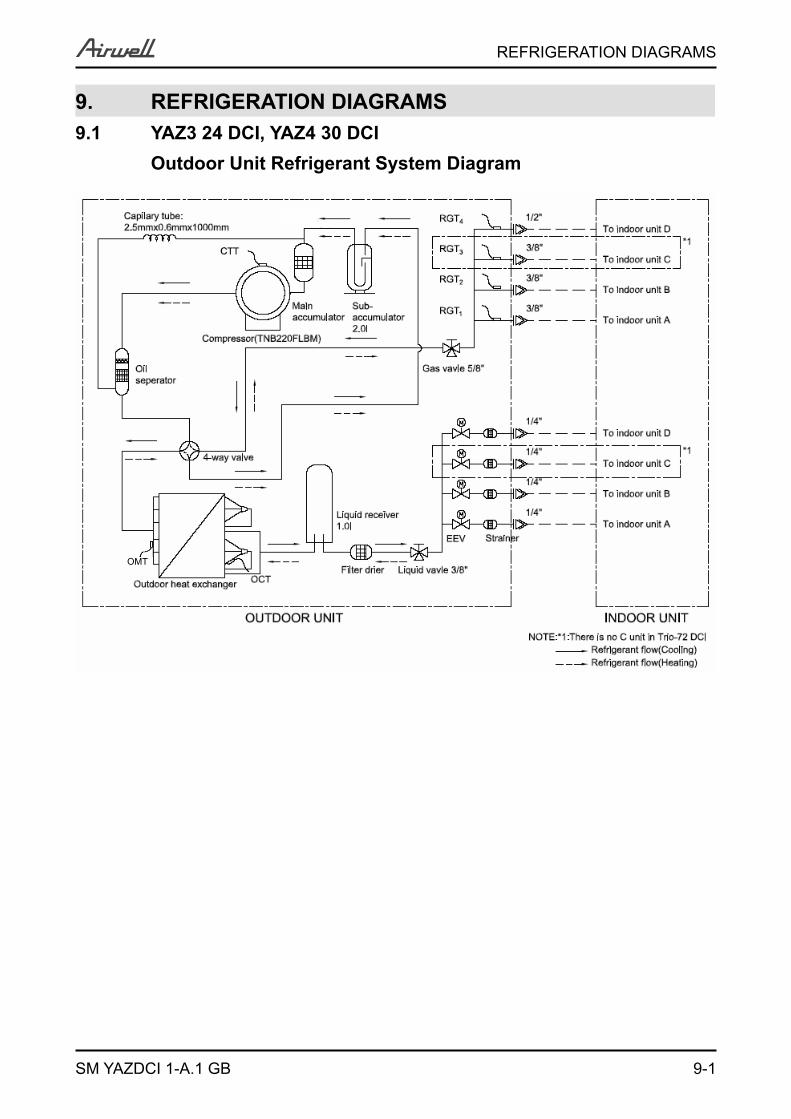
9. REFRIGERATION DIAGRAMS9.1 YAZ3 24 DCI, YAZ4 30 DCI Outdoor Unit Refrigerant System Diagram
OMT
10-1
TUBING CONNECTIONS
SM YAZDCI 1-A.1 GB
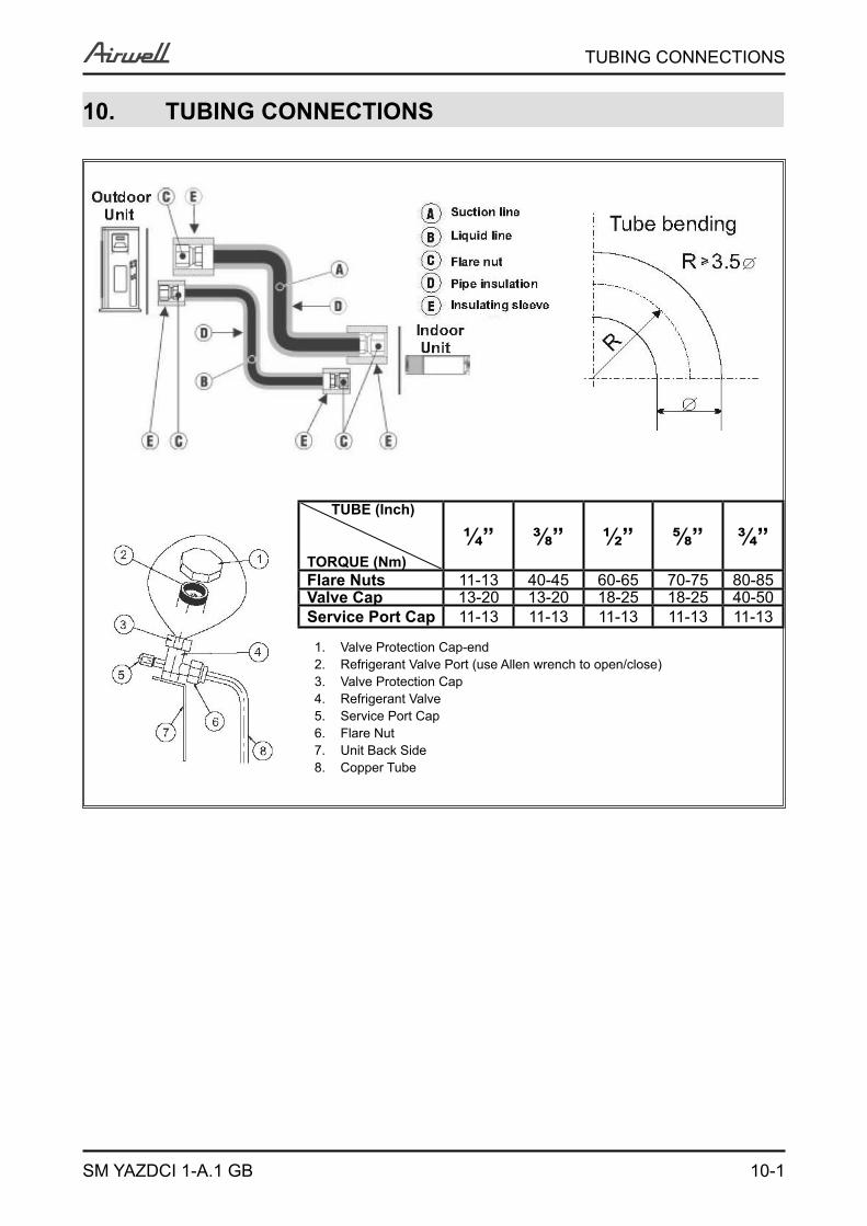
10. TUBING CONNECTIONS
TUBE (Inch)
TORQUE (Nm)¼” ⅜” ½” ⅝” ¾”
Flare Nuts 11-13 40-45 60-65 70-75 80-85Valve Cap 13-20 13-20 18-25 18-25 40-50Service Port Cap 11-13 11-13 11-13 11-13 11-13
1. Valve Protection Cap-end2. Refrigerant Valve Port (use Allen wrench to open/close)3. Valve Protection Cap4. Refrigerant Valve5. Service Port Cap6. Flare Nut7. Unit Back Side8. Copper Tube
11-1
CONTROL SYSTEM
SM YAZDCI 1-A.1 GB
11. CONTROL SYSTEM11.1 Abbreviations
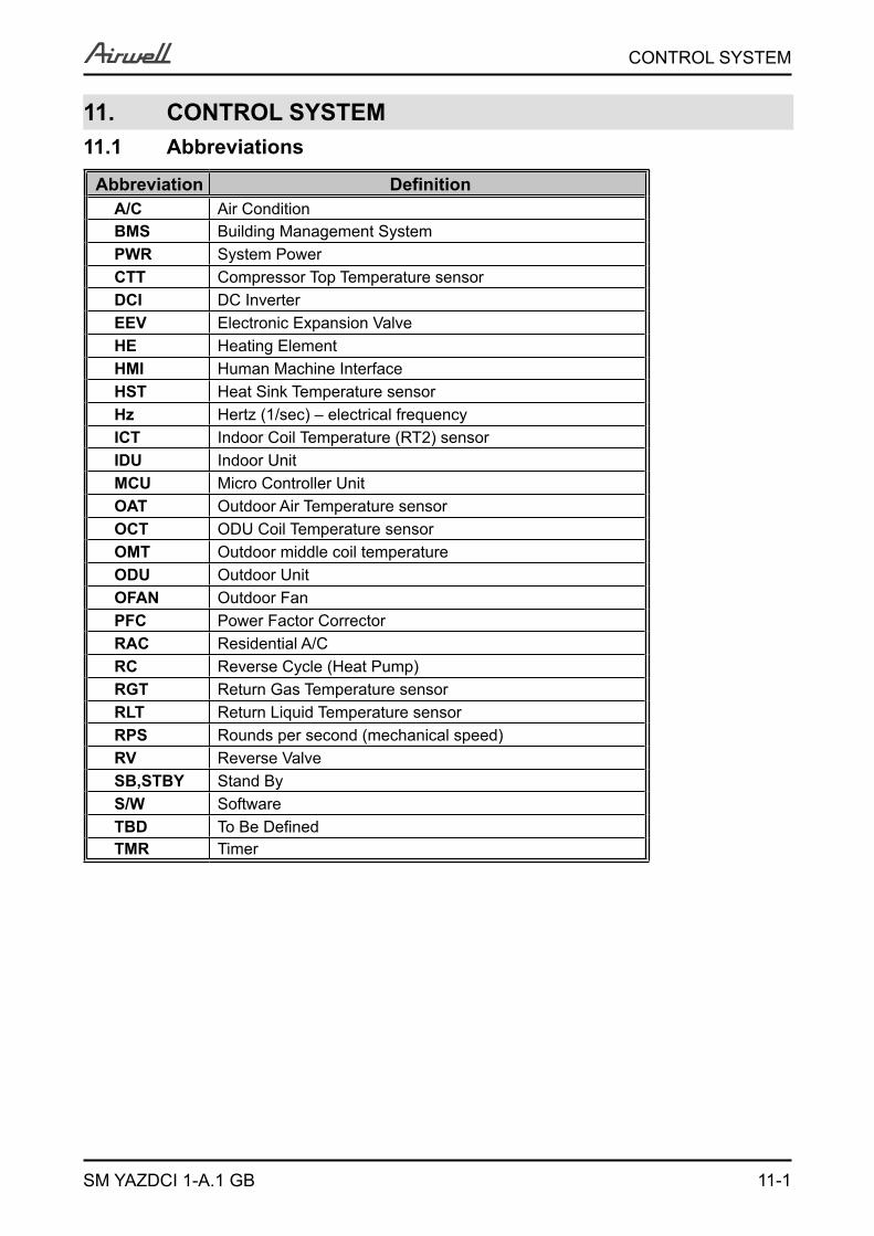
Abbreviation DefinitionA/C Air Condition BMS Building Management SystemPWR System PowerCTT Compressor Top Temperature sensorDCI DC InverterEEV Electronic Expansion ValveHE Heating ElementHMI Human Machine Interface HST Heat Sink Temperature sensorHz Hertz (1/sec) – electrical frequencyICT Indoor Coil Temperature (RT2) sensorIDU Indoor UnitMCU Micro Controller UnitOAT Outdoor Air Temperature sensorOCT ODU Coil Temperature sensorOMT Outdoor middle coil temperatureODU Outdoor UnitOFAN Outdoor FanPFC Power Factor CorrectorRAC Residential A/CRC Reverse Cycle (Heat Pump)RGT Return Gas Temperature sensorRLT Return Liquid Temperature sensorRPS Rounds per second (mechanical speed)RV Reverse ValveSB,STBY Stand ByS/W SoftwareTBD To Be Defined TMR Timer
11-2
CONTROL SYSTEM
SM YAZDCI 1-A.1 GB
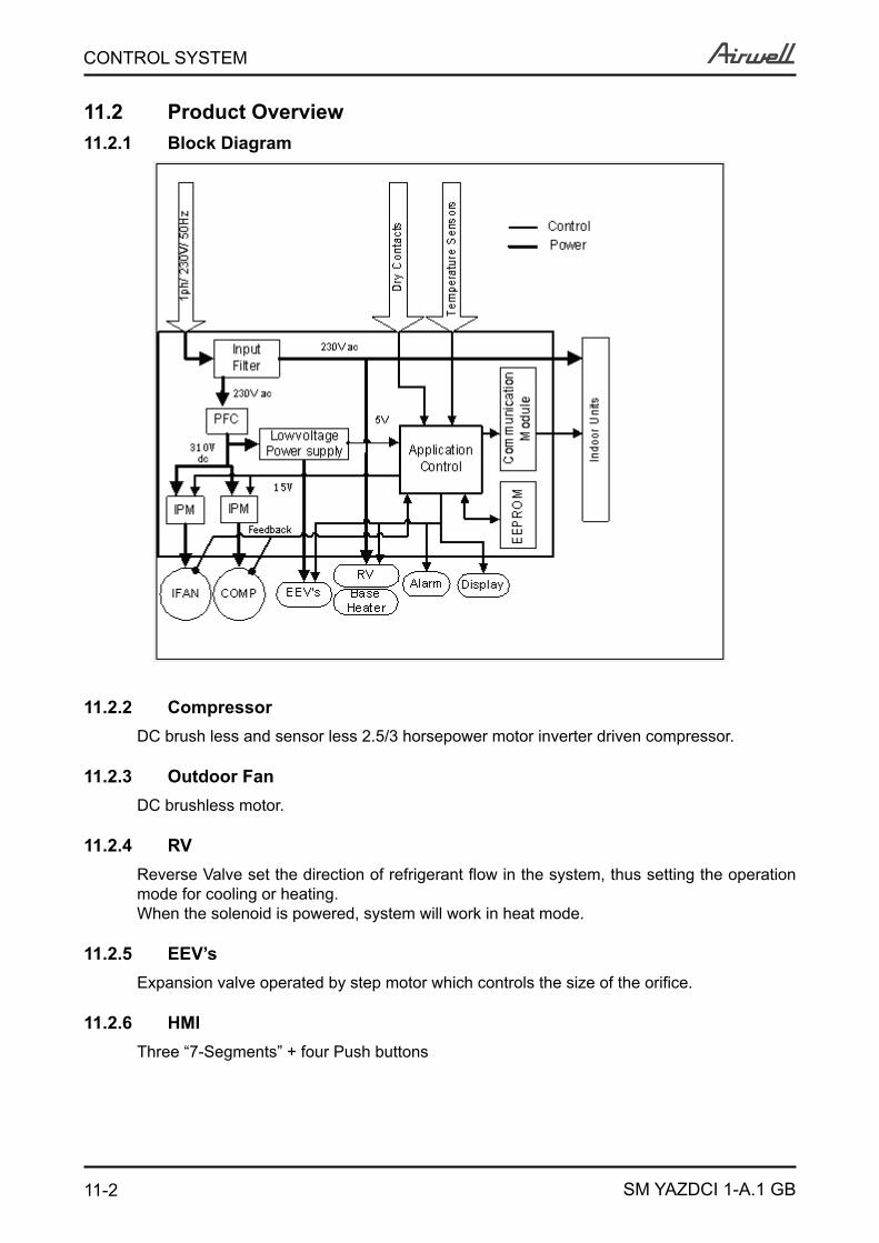
11.2 Product Overview11.2.1 Block Diagram
11.2.2 CompressorDC brush less and sensor less 2.5/3 horsepower motor inverter driven compressor.
11.2.3 Outdoor FanDC brushless motor.
11.2.4 RVReverse Valve set the direction of refrigerant flow in the system, thus setting the operation mode for cooling or heating.When the solenoid is powered, system will work in heat mode.
11.2.5 EEV’sExpansion valve operated by step motor which controls the size of the orifice.
11.2.6 HMIThree “7-Segments” + four Push buttons
11-3
CONTROL SYSTEM
SM YAZDCI 1-A.1 GB
11.2.7 Dry ContactsDry contacts are used to interface the system with an external building management system (BMS).Night input. Switches the system to night mode when closed.
During night mode, the outdoor unit speed will be reduced in order to reduce the system noise level.
SB input. System will be turned to Stand-by when the contact is closed.Power Shedding input. Limits the maximum power consumption when closed.Forced Mode input. Used to force the operation mode of the systemAlarm output indicates a failure at the system.
Alarm output will be activated when there in the following ODU Faults/Protections1 to 7, 11,13 to19, 24 to 26, 28 to 29, 311.
Alarm output will be OFF when the Fault/Protection is cleared.
11.2.8 Temperature SensorsCTT – Compressor Top TemperatureOAT – Outdoor Air TemperatureOMT– Outdoor middle coil temperatureOCT – Outdoor Coil (heat exchanger) TemperatureHST – Heat Sink TemperatureRGT11..4 – Indoor Unit 11..4 Returned Gas TemperaturesRLT 11..4 – Indoor Unit 11..4 Returned Liquid Temperatures
11.2.9 Base HeaterHeating element designed to melt any ice that is accumulated on the outdoor unit base during low heating operation.
11.3 General Operating Rules11.3.1 Initialization
Initialization process is the first operation done each time power is up.The targets of the initialization are:Addressing of IDU’s
Identification of connected IDU’s
IDU Matching Check
EEV’s homing (reset position)
Restoring Parameters from EEPROM/Jumpers/Dipswitches
11-4
CONTROL SYSTEM
SM YAZDCI 1-A.1 GB
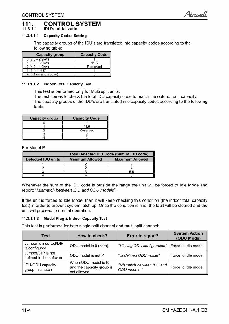
111. CONTROL SYSTEM11.3.1.1 IDU’s Initializatio11.3.1.1.1 Capacity Codes Setting
The capacity groups of the IDU’s are translated into capacity codes according to the following table:
Capacity group Capacity Code0 (2.0 - 2.9kw) 11 (3.0 - 3.9kw) 11.52 (4.0 - 4.9kw) Reserved3 (5.0 to 6.0) 24 (6.1kw and above) 3
11.3.1.1.2 Indoor Total Capacity Test
This test is performed only for Multi split units.The test comes to check the total IDU capacity code to match the outdoor unit capacity.The capacity groups of the IDU’s are translated into capacity codes according to the following table:
Capacity group Capacity Code0 11 11.52 Reserved3 24 3
For Model P:Total Detected IDU Code (Sum of IDU code)
Detected IDU units Minimum Allowed Maximum Allowed1 2 22 2 43 3 5.54 4 6
Whenever the sum of the IDU code is outside the range the unit will be forced to Idle Mode and report: “Mismatch between IDU and ODU models”.
If the unit is forced to Idle Mode, then it will keep checking this condition (the indoor total capacity test) in order to prevent system latch up. Once the condition is fine, the fault will be cleared and the unit will proceed to normal operation.
11.3.1.1.3 Model Plug & Indoor Capacity Test
This test is performed for both single split channel and multi split channel:
Test How to check? Error to report? System Action(ODU Mode)
Jumper is inserted/DIP is configured ODU model is 0 (zero). “Missing ODU configuration” Force to Idle mode.
Jumper/DIP is not defined in the software ODU model is not P. “Undefined ODU model” Force to Idle mode
IDU-ODU capacity group mismatch
When ODU model is P, and the capacity group is not allowed.
“Mismatch between IDU and ODU models “ Force to Idle mode
11-5
CONTROL SYSTEM
SM YAZDCI 1-A.1 GB
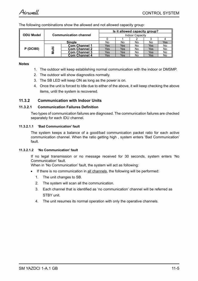
The following combinations show the allowed and not allowed capacity group:
ODU Model Communication channelIs it allowed capacity group?
Indoor Capacity0 1 2 3 4
P (DCI80)
Single No No No No Yes
Mul
ti Com Channel 1 Yes Yes No Yes NoCom Channel 2 Yes Yes No Yes NoCom Channel 3 Yes Yes No Yes NoCom Channel 4 Yes Yes No Yes No
NotesThe outdoor will keep establishing normal communication with the indoor or DMSMP.1. The outdoor will show diagnostics normally.2. The SB LED will keep ON as long as the power is on.3. Once4. the unit is forced to Idle due to either of the above, it will keep checking the above items, until the system is recovered.
11.3.2 Communication with Indoor Units 11.3.2.1 Communication Failures Definition
Two types of communication failures are diagnosed. The communication failures are checked separately for each IDU channel.
11.3.2.1.1 ‘Bad Communication’ fault
The system keeps a balance of a good/bad communication packet ratio for each active communication channel. When the ratio getting high , system enters ‘Bad Communication’ fault.
11.3.2.1.2 ‘No Communication’ fault
If no legal transmission or no message received for 30 seconds, system enters ‘No Communication’ fault.When in ‘No Communication’ fault, the system will act as following:
If there is no communication in all channels, the following will be performed:The1. unit changes to SB.The2. system will scan all the communication.Each3. channel that is identified as ‘no communication’ channel will be referred as STBY unit. The4. unit resumes its normal operation with only the operative channels.
11-6
CONTROL SYSTEM
SM YAZDCI 1-A.1 GB
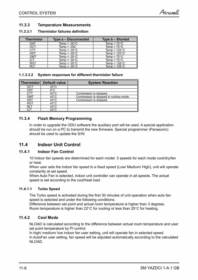
11.3.3 Temperature Measurements11.3.3.1 Thermistor failures definition
Thermistor Type a – Disconnected Type b – ShortedOAT Temp < -30 oC Temp > 75 oCOCT Temp < -35C Temp > 75 oCCTT Temp < -30 oC Temp > 125 oCHST Temp < -30 oC Temp > 125 oCOMT Temp < -35 oC Temp > 75 oCICT Temp < -30 oC Temp > 75 oCRGT Temp < -30 oC Temp > 126 oCRLT Temp < -30 oC Temp > 126 oC
1.1.3.3.2 System responses for different thermistor failure
Thermistor Default value System ReactionOCT 43°COAT 6°CCTT 43°C Compressor is stopped.OMT 43°C Compressor is stopped in cooling mode.HST 43°C Compressor is stopped.RGT 43°CRLT 43°CICT 43°C
11.3.4 Flash Memory ProgrammingIn order to upgrade the ODU software the auxiliary port will be used. A special application should be run on a PC to transmit the new firmware. Special programmer (Panasonic) should be used to update the S/W.
11.4 Indoor Unit Control11.4.1 Indoor Fan Control
10 Indoor fan speeds are determined for each model. 5 speeds for each mode cool/dry/fan or heat.When user sets the indoor fan speed to a fixed speed (Low/ Medium/ High), unit will operate constantly at set speed. When Auto Fan is selected, indoor unit controller can operate in all speeds. The actual speed is set according to the cool/heat load.
11.4.1.1 Turbo Speed
The Turbo speed is activated during the first 30 minutes of unit operation when auto fan speed is selected and under the following conditions:Difference between set point and actual room temperature is higher than 3 degrees.Room temperature is higher than 22C for cooling or less than 25C for heating.
11.4.2 Cool ModeNLOAD is calculated according to the difference between actual room temperature and user set point temperature by PI control.In high/ medium/ low indoor fan user setting, unit will operate fan in selected speed.In AutoFan user setting, fan speed will be adjusted automatically according to the calculated NLOAD.
11-7
CONTROL SYSTEM
SM YAZDCI 1-A.1 GB
11.4.3 Heat ModeNLOAD is calculated according to the difference between actual room temperature and user set point temperature by PI control.In high/ medium/ low indoor fan user setting, unit will operate fan in selected speed.In AutoFan user setting, fan speed will be adjusted automatically according to the calculated NLOAD.
11.4.3.1 Temperature Compensation
In wall mounted, ducted, and cassette models, 3 degrees are reduced from room temperature reading (except when in I-Feel mode), to compensate for temperature difference between high and low areas in the heated room, and for coil heat radiation on room thermistor.The temperature compensation can be enabled/disabled by shortening of J2 on the indoor unit controller.
Model J2 Shorted J2 OpenedWall mounted Compensation Disabled Compensation EnabledCassette Compensation Enabled Compensation DisabledDucted Compensation Enabled Compensation DisabledFloor/Ceiling Compensation Disabled Compensation Enabled
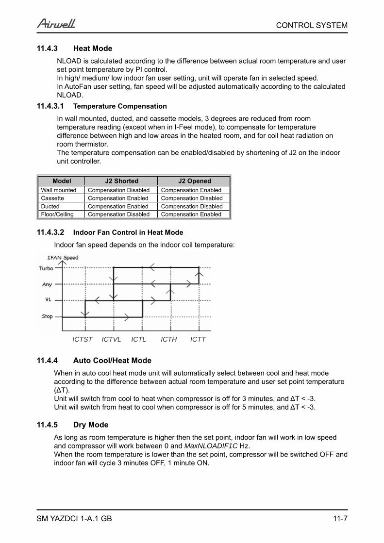
11.4.3.2 Indoor Fan Control in Heat Mode
Indoor fan speed depends on the indoor coil temperature:
ICTST ICTVL ICTL ICTH ICTT
11.4.4 Auto Cool/Heat ModeWhen in auto cool heat mode unit will automatically select between cool and heat mode according to the difference between actual room temperature and user set point temperature (ΔT).Unit will switch from cool to heat when compressor is off for 3 minutes, and ΔT < -3.Unit will switch from heat to cool when compressor is off for 5 minutes, and ΔT < -3.
11.4.5 Dry ModeAs long as room temperature is higher then the set point, indoor fan will work in low speed and compressor will work between 0 and MaxNLOADIF1C Hz.When the room temperature is lower than the set point, compressor will be switched OFF and indoor fan will cycle 3 minutes OFF, 1 minute ON.
11-8
CONTROL SYSTEM
SM YAZDCI 1-A.1 GB
11.4.6 Indoor Units Operation when Indoor Unit Mode is Different than Outdoor Unit Mode
Open louvers according to user selection. Indoor fan is forced to OFF.
11.4.7 Heating Element ControlHeating element can be lit on if LOAD > 0.8 * MaximumNLOAD AND Indoor Coil temperature < 45C.The heating element will be off when LOAD < 0.5 * MaximumNLOAD OR if Indoor Coil temperature > 50C.
11.4.8 Ioniser ControlLEX Family - Ioniser is on when unit is on AND indoor fan is on AND Ioniser power switch (on Ioniser) is on.
11.4.9 Electro Static Filter (ESF) ControlLEX Family - ESF is on when ESF switch is on, Safety switch is pressed, unit is on, AND indoor fan is on.
11.4.10 Indoor Unit Dry ContactIndoor unit Dry contact has two alternative functions that are selected by J9.
Status Function Contact = Open Contact = ShortJ9 = Open Presence Detector Connection No Limit Forced to STBYJ9 = Short Power Shedding Function No Limit Limit NLOAD
11.4.11 Operating the Unit from the Mode ButtonForced operation allows to start, stop and operate in Cooling or Heating, in pre-set temperature according to the following table:
Forced operation Mode Pre-set TemperatureCooling 200CHeating 280C
11.4.12 On Unit Controls and Indicators11.4.12.1 All Models Except for Floor/Ceiling model
STAND BYINDICATOR
Lights up when the Air Conditioner is connected to power and ready to receive the R/C commands
OPERATION INDICATOR
Lights up during operation.Blinks for 300 msec to announce that a R/C infrared signal has been received and stored.Blinks continuously during protections (according to the relevant spec section).
TIMER INDICATOR Lights up during Timer and Sleep operation.FILTER INDICATOR Lights up when Air Filter needs to be cleaned.
COOLING INDICATOR Lights up when system is switched to Cool Mode by using the Mode Switch on the unit.HEATING INDICATOR Lights up when system is switched Heat Mode by using the Mode Switch on the unit.
Mode SWITCH(COOL/HEAT/OFF)
Every short pressing , the next operation mode is selected, in this order :SB → Cool Mode → Heat Mode → SB → …In long pressing system enters diagnostic mode.
RESET / FILTERSWITCH
For short pressing:When Filter LED is on - turn off the FILTER INDICATOR after a clean filter has been reinstalled.When Filter LED is off – enable/disable the buzzer announcer, if selected.
11-9
CONTROL SYSTEM
SM YAZDCI 1-A.1 GB
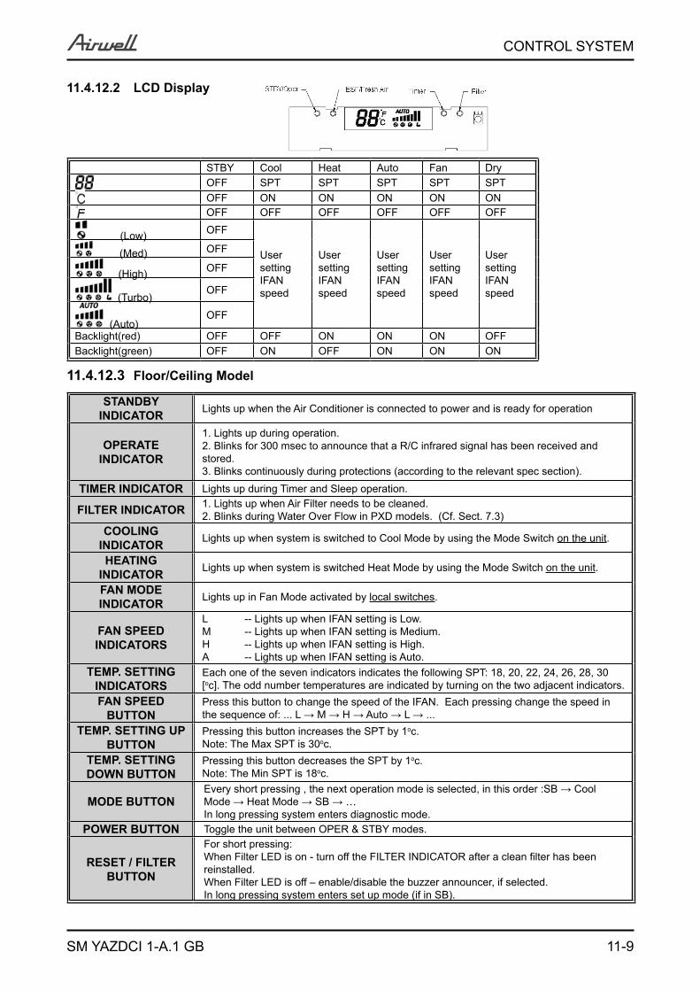
11.4.12.2 LCD Display
STBY Cool Heat Auto Fan DryOFF SPT SPT SPT SPT SPTOFF ON ON ON ON ONOFF OFF OFF OFF OFF OFF
(Low) OFF
User setting IFAN speed
User setting IFAN speed
User setting IFAN speed
User setting IFAN speed
User setting IFAN speed
(Med) OFF
(High) OFF
(Turbo)OFF
(Auto)OFF
Backlight(red) OFF OFF ON ON ON OFFBacklight(green) OFF ON OFF ON ON ON
11.4.12.3 Floor/Ceiling Model
STANDBY INDICATOR Lights up when the Air Conditioner is connected to power and is ready for operation
OPERATE INDICATOR
1. Lights up during operation.2. Blinks for 300 msec to announce that a R/C infrared signal has been received and stored.3. Blinks continuously during protections (according to the relevant spec section).
TIMER INDICATOR Lights up during Timer and Sleep operation.
FILTER INDICATOR 1. Lights up when Air Filter needs to be cleaned.2. Blinks during Water Over Flow in PXD models. (Cf. Sect. 7.3)
COOLING INDICATOR Lights up when system is switched to Cool Mode by using the Mode Switch on the unit.
HEATING INDICATOR Lights up when system is switched Heat Mode by using the Mode Switch on the unit.
FAN MODE INDICATOR Lights up in Fan Mode activated by local switches.
FAN SPEED INDICATORS
L -- Lights up when IFAN setting is Low.M -- Lights up when IFAN setting is Medium.H -- Lights up when IFAN setting is High.A -- Lights up when IFAN setting is Auto.
TEMP. SETTING INDICATORS
Each one of the seven indicators indicates the following SPT: 18, 20, 22, 24, 26, 28, 30 [oc]. The odd number temperatures are indicated by turning on the two adjacent indicators.
FAN SPEED BUTTON
Press this button to change the speed of the IFAN. Each pressing change the speed in the sequence of: ... L → M → H → Auto → L → ...
TEMP. SETTING UP BUTTON
Pressing this button increases the SPT by 1oc.Note: The Max SPT is 30oc.
TEMP. SETTING DOWN BUTTON
Pressing this button decreases the SPT by 1oc.Note: The Min SPT is 18oc.
MODE BUTTONEvery short pressing , the next operation mode is selected, in this order :SB → Cool Mode → Heat Mode → SB → …In long pressing system enters diagnostic mode.
POWER BUTTON Toggle the unit between OPER & STBY modes.
RESET / FILTERBUTTON
For short pressing:When Filter LED is on - turn off the FILTER INDICATOR after a clean filter has been reinstalled.When Filter LED is off – enable/disable the buzzer announcer, if selected.In long pressing system enters set up mode (if in SB).
11-10
CONTROL SYSTEM
SM YAZDCI 1-A.1 GB
11.5 Run ModeRun mode is the default operation mode of the system. This is the standard operation mode that is active in field application (at customer site).System can go from run mode to other operation modes through keyboard or serial ports.
11.5.1 Mode SettingMode defines the ODU operation mode. There are three possible operation modes:
1. STBY – standby mode
2. COOL - the unit operating at cooling cycle
3. HEAT - the unit operating at heat pump cycleThe ODU define the system operation mode according to three methods set by the display key board:
1. First request priority The first IDU which requests different mode than STBY mode will set the new operation mode. The mode will change once all the units exit the current operation mode.
2. Priority unitIf an IDU is defined as a priority unit, the operational mode will be defined according to that unit request, unless the unit is at STBY mode.In case priority unit is SB the mode will be set acceding to first request priority.
3. Forced operation modeIf forced mode is enabled than the ODU mode will be forced according to the Forced mode input:Open COOLShort HEATThe ODU will go to SB if all the IDU are at SB or at different modes.
4. SB InputThe ODU will change mode between COOL/HEAT and Idle according to the STBY dry contact input as follows:
STBY input ODU modeShort SBShort Open last modeOpen according normal mode selection
11.5.2 Compressor Speed Control11.5.2.1 Compressor Min On/Off time
Compressor minimum OFF time is MinOFFTime minutes except during Deicing protection. Compressor minimum ON time is MinOnTime minutes, minimum ON time is ignored during protections, and when unit is turned to STBY.
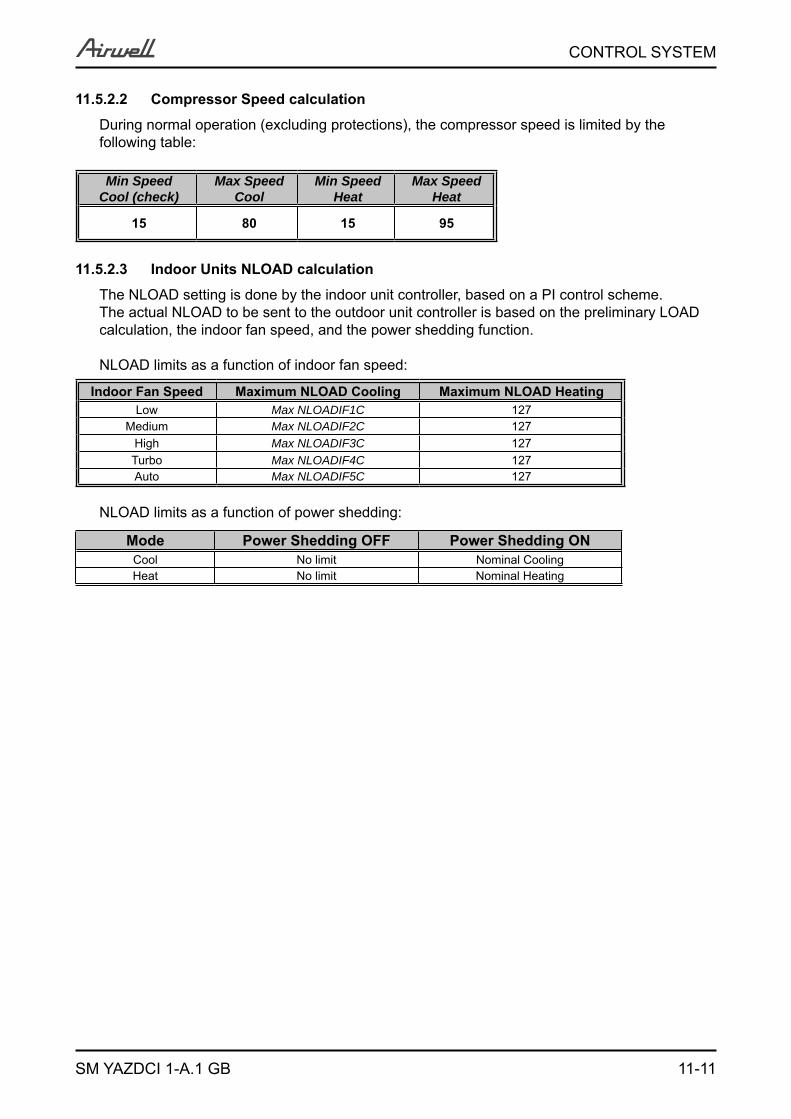
11-11
CONTROL SYSTEM
SM YAZDCI 1-A.1 GB
11.5.2.2 Compressor Speed calculation
During normal operation (excluding protections), the compressor speed is limited by the following table:
Min SpeedCool (check)
Max SpeedCool
Min SpeedHeat
Max SpeedHeat
15 80 15 95
11.5.2.3 Indoor Units NLOAD calculation
The NLOAD setting is done by the indoor unit controller, based on a PI control scheme.The actual NLOAD to be sent to the outdoor unit controller is based on the preliminary LOAD calculation, the indoor fan speed, and the power shedding function.
NLOAD limits as a function of indoor fan speed:
Indoor Fan Speed Maximum NLOAD Cooling Maximum NLOAD HeatingLow Max NLOADIF1C 127
Medium Max NLOADIF2C 127High Max NLOADIF3C 127Turbo Max NLOADIF4C 127Auto Max NLOADIF5C 127
NLOAD limits as a function of power shedding:
Mode Power Shedding OFF Power Shedding ONCool No limit Nominal CoolingHeat No limit Nominal Heating
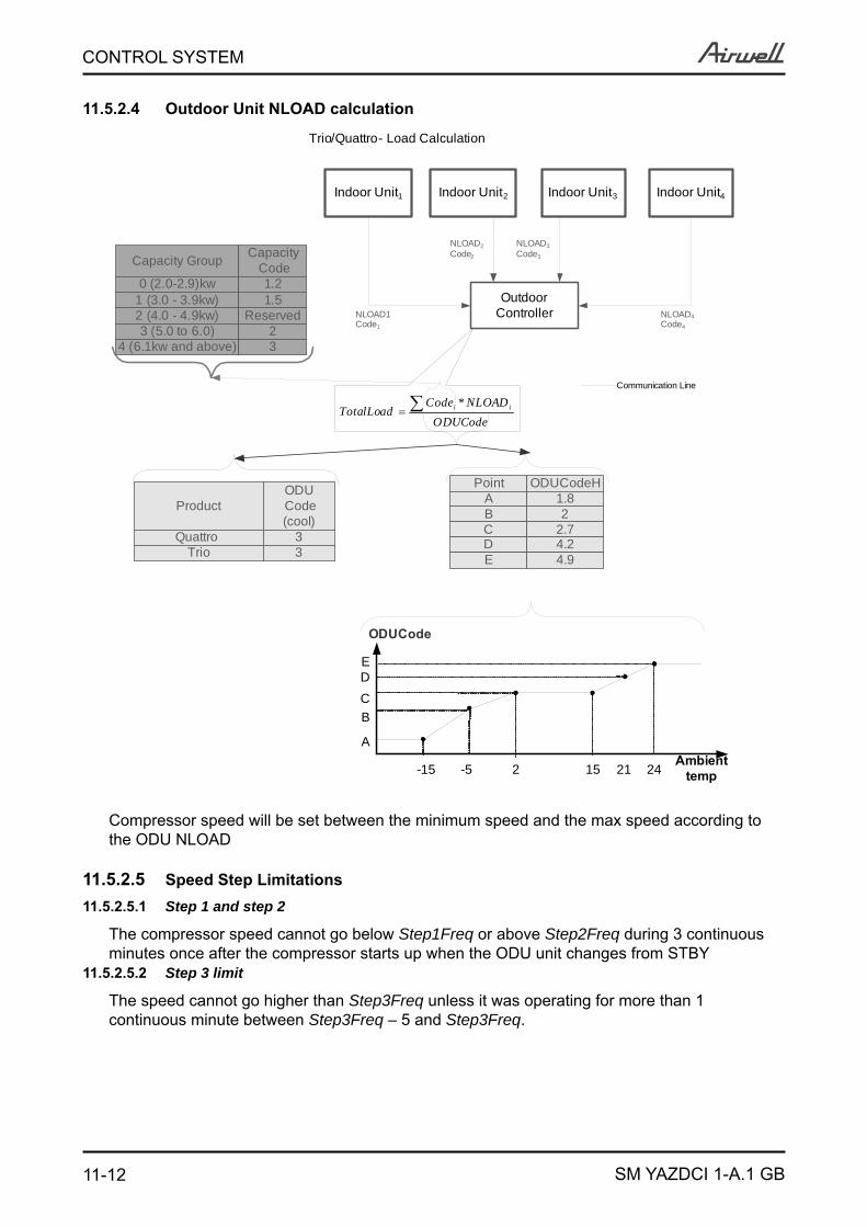
11-12
CONTROL SYSTEM
SM YAZDCI 1-A.1 GB
11.5.2.4 Outdoor Unit NLOAD calculation
Indoor Unit2 Indoor Unit3 Indoor Unit4
OutdoorController
NLOAD2Code2
NLOAD3Code3
NLOAD4Code4
Communication Line
Trio/Quattro- Load Calculation
ODUCodeNLOADCode
TotalLoad ii *
Capacity Group Capacity Code
0 (2.0-2.9)kw 1.21 (3.0 - 3.9kw) 1.5 2 (4.0 - 4.9kw) Reserved3 (5.0 to 6.0) 2
4 (6.1kw and above) 3
ProductODU Code (cool)
Quattro 3Trio 3
Indoor Unit1
NLOAD1Code1
-15 -5 15
ODUCode
Ambient temp2 2421
A
BCDE
Point ODUCodeHABCDE
1.82
2.74.24.9
Compressor speed will be set between the minimum speed and the max speed according to the ODU NLOAD
11.5.2.5 Speed Step Limitations11.5.2.5.1 Step 1 and step 2
The compressor speed cannot go below Step1Freq or above Step2Freq during 3 continuous minutes once after the compressor starts up when the ODU unit changes from STBY
11.5.2.5.2 Step 3 limit
The speed cannot go higher than Step3Freq unless it was operating for more than 1 continuous minute between Step3Freq – 5 and Step3Freq.
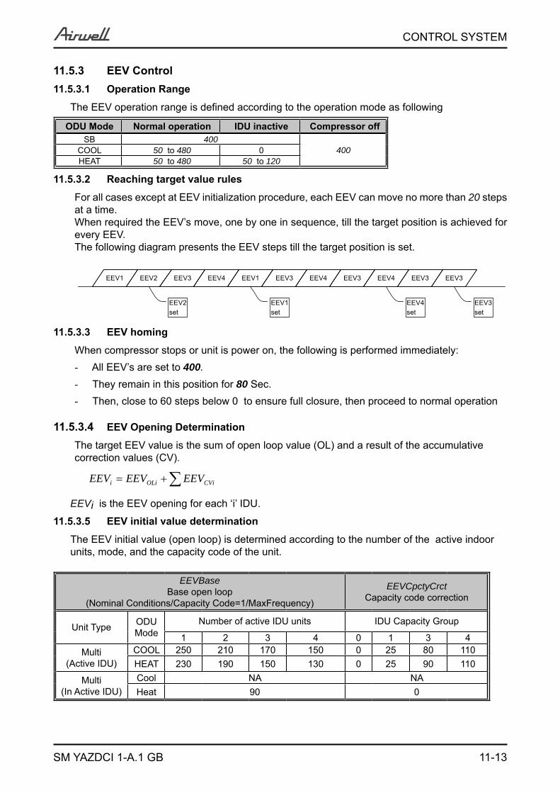
11-13
CONTROL SYSTEM
SM YAZDCI 1-A.1 GB
11.5.3 EEV Control11.5.3.1 Operation Range
The EEV operation range is defined according to the operation mode as following
ODU Mode Normal operation IDU inactive Compressor offSB 400
400COOL 50 to 480 0HEAT 50 to 480 50 to 120
11.5.3.2 Reaching target value rules
For all cases except at EEV initialization procedure, each EEV can move no more than 20 steps at a time.When required the EEV’s move, one by one in sequence, till the target position is achieved for every EEV.The following diagram presents the EEV steps till the target position is set.
EEV1 EEV2 EEV3 EEV4 EEV1 EEV3 EEV4 EEV3 EEV4 EEV3 EEV3
EEV2set
EEV1set
EEV4set
EEV3set
11.5.3.3 EEV homing
When compressor stops or unit is power on, the following is performed immediately: All EEV’s are set to - 400. They remain in this position for - 80 Sec. Then, close to 60 steps below 0 to ensure full closure, then proceed to normal operation-
11.5.3.4 EEV Opening Determination
The target EEV value is the sum of open loop value (OL) and a result of the accumulative correction values (CV).
CViOLii EEVEEVEEV
EEVi is the EEV opening for each ‘i’ IDU.
11.5.3.5 EEV initial value determination
The EEV initial value (open loop) is determined according to the number of the active indoor units, mode, and the capacity code of the unit.
EEVBaseBase open loop
(Nominal Conditions/Capacity Code=1/MaxFrequency)
EEVCpctyCrctCapacity code correction
Unit Type ODUMode
Number of active IDU units IDU Capacity Group
1 2 3 4 0 1 3 4Multi
(Active IDU)COOL 250 210 170 150 0 25 80 110HEAT 230 190 150 130 0 25 90 110
Multi(In Active IDU)
Cool NA NAHeat 90 0
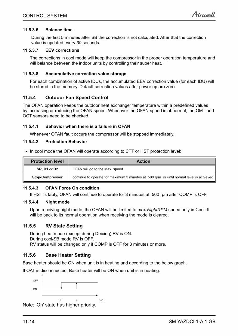
11-14
CONTROL SYSTEM
SM YAZDCI 1-A.1 GB
11.5.3.6 Balance time
During the first 5 minutes after SB the correction is not calculated. After that the correction value is updated every 30 seconds.
11.5.3.7 EEV corrections
The corrections in cool mode will keep the compressor in the proper operation temperature and will balance between the indoor units by controlling their super heat.
11.5.3.8 Accumulative correction value storage
For each combination of active IDUs, the accumulated EEV correction value (for each IDU) will be stored in the memory. Default correction values after power up are zero.
11.5.4 Outdoor Fan Speed ControlThe OFAN operation keeps the outdoor heat exchanger temperature within a predefined values by increasing or reducing the OFAN speed. Whenever the OFAN speed is abnormal, the OMT and OCT sensors need to be checked.
11.5.4.1 Behavior when there is a failure in OFAN
Whenever OFAN fault occurs the compressor will be stopped immediately.
11.5.4.2 Protection Behavior
In cool mode the OFAN will operate according to CTT or HST protection level:
Protection level ActionSR, D1 or D2 OFAN will go to the Max. speed
Stop-Compressor continue to operate for maximum 3 minutes at 500 rpm or until normal level is achieved.
11.5.4.3 OFAN Force On conditionIf HST is fauty, OFAN will continue to operate for 3 minutes at 500 rpm after COMP is OFF.
11.5.4.4 Night mode
Upon receiving night mode, the OFAN will be limited to max NightRPM speed only in Cool. It will be back to its normal operation when receiving the mode is cleared.
11.5.5 RV State SettingDuring heat mode (except during Deicing) RV is ON. During cool/SB mode RV is OFF.RV status will be changed only if COMP is OFF for 3 minutes or more.
11.5.6 Base Heater SettingBase heater should be ON when unit is in heating and according to the below graph.
If OAT is disconnected, Base heater will be ON when unit is in heating.
Note: ‘On’ state has higher priority.OAT
ON
OFF
-2 0
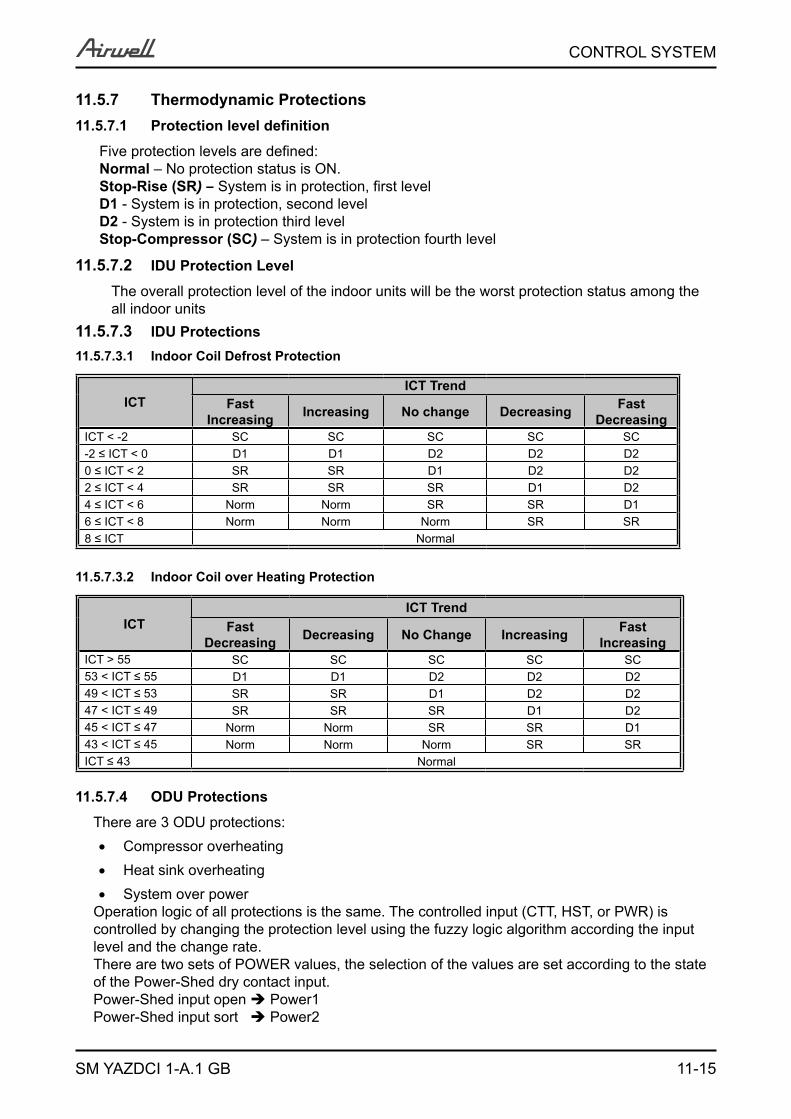
11-15
CONTROL SYSTEM
SM YAZDCI 1-A.1 GB
11.5.7 Thermodynamic Protections11.5.7.1 Protection level definition
Five protection levels are defined:Normal – No protection status is ON.Stop-Rise (SR) – System is in protection, first levelD1 - System is in protection, second levelD2 - System is in protection third levelStop-Compressor (SC) – System is in protection fourth level
11.5.7.2 IDU Protection Level
The overall protection level of the indoor units will be the worst protection status among the all indoor units
11.5.7.3 IDU Protections11.5.7.3.1 Indoor Coil Defrost Protection
ICTICT Trend
Fast Increasing Increasing No change Decreasing Fast
DecreasingICT < -2 SC SC SC SC SC-2 ≤ ICT < 0 D1 D1 D2 D2 D20 ≤ ICT < 2 SR SR D1 D2 D22 ≤ ICT < 4 SR SR SR D1 D24 ≤ ICT < 6 Norm Norm SR SR D16 ≤ ICT < 8 Norm Norm Norm SR SR8 ≤ ICT Normal
11.5.7.3.2 Indoor Coil over Heating Protection
ICTICT Trend
Fast Decreasing Decreasing No Change Increasing Fast
IncreasingICT > 55 SC SC SC SC SC53 < ICT ≤ 55 D1 D1 D2 D2 D249 < ICT ≤ 53 SR SR D1 D2 D247 < ICT ≤ 49 SR SR SR D1 D245 < ICT ≤ 47 Norm Norm SR SR D143 < ICT ≤ 45 Norm Norm Norm SR SRICT ≤ 43 Normal
11.5.7.4 ODU Protections
There are 3 ODU protections:Compressor overheating
Heat sink overheating
System over powerOperation logic of all protections is the same. The controlled input (CTT, HST, or PWR) is controlled by changing the protection level using the fuzzy logic algorithm according the input level and the change rate.There are two sets of POWER values, the selection of the values are set according to the state of the Power-Shed dry contact input.Power-Shed input open Power1Power-Shed input sort Power2
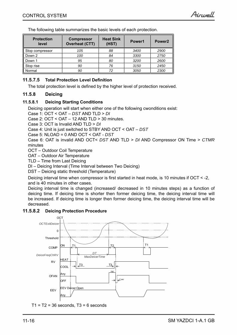
11-16
CONTROL SYSTEM
SM YAZDCI 1-A.1 GB
The following table summarizes the basic levels of each protection.
Protectionlevel
CompressorOverheat (CTT)
Heat Sink(HST) Power1 Power2
Stop compressor 105 88 3400 2900Down 2 100 84 3300 2750Down 1 95 80 3200 2600Stop rise 90 76 3150 2450Normal 90 72 3050 2300
11.5.7.5 Total Protection Level DefinitionThe total protection level is defined by the higher level of protection received.
11.5.8 Deicing11.5.8.1 Deicing Starting Conditions
Deicing operation will start when either one of the following cwonditions exist:Case 1: OCT < OAT – DST AND TLD > DICase 2: OCT < OAT – 12 AND TLD > 30 minutes.Case 3: OCT is Invalid AND TLD > DICase 4: Unit is just switched to STBY AND OCT < OAT – DSTCase 5: NLOAD = 0 AND OCT < OAT - DSTCase 6: OAT is invalid AND OCT< DST AND TLD > DI AND Compressor ON Time > CTMR minutesOCT – Outdoor Coil TemperatureOAT – Outdoor Air TemperatureTLD – Time from Last DeicingDI – Deicing Interval (Time Interval between Two Deicing)DST – Deicing static threshold (Temperature)Deicing interval time when compressor is first started in heat mode, is 10 minutes if OCT < -2, and is 40 minutes in other cases.Deicing interval time is changed (increased/ decreased in 10 minutes steps) as a function of deicing time. If deicing time is shorter then former deicing time, the deicing interval time will be increased. If deicing time is longer then former deicing time, the deicing interval time will be decreased.
11.5.8.2 Deicing Protection Procedure
COMP
RV
OFAN
EEV
ON
HEAT
COOL
Any
OFF
EEV Deicer Open
Any
T1 T2
T3 T3
T1
DTMaxDeicerTime
OCT
DeiceFreqChRV
0
Threshold
780
OCTExitDeicer
2 sec
T1 = T2 = 36 seconds, T3 = 6 seconds
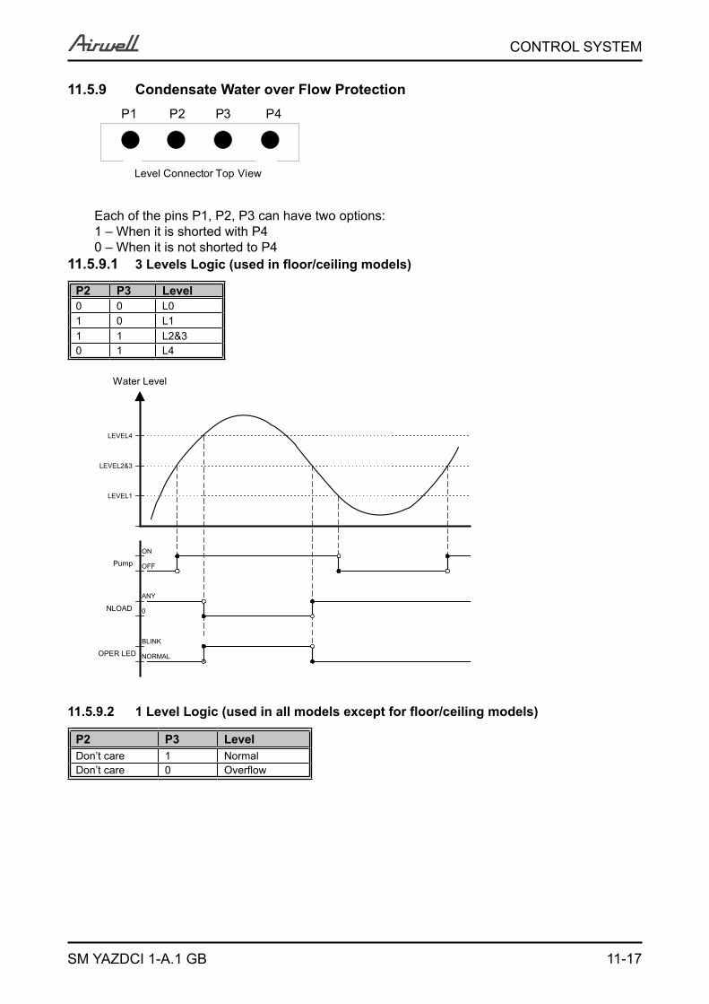
11-17
CONTROL SYSTEM
SM YAZDCI 1-A.1 GB
11.5.9 Condensate Water over Flow ProtectionP1 P2 P3 P4
Level Connector Top View
Each of the pins P1, P2, P3 can have two options:1 – When it is shorted with P40 – When it is not shorted to P4
11.5.9.1 3 Levels Logic (used in floor/ceiling models)
P2 P3 Level0 0 L01 0 L11 1 L2&30 1 L4
Water Level
ANY
0
BLINK
NLOAD
OPER LED
LEVEL1
LEVEL2&3
LEVEL4
NORMAL
ON
Pump OFF
11.5.9.2 1 Level Logic (used in all models except for floor/ceiling models)
P2 P3 LevelDon’t care 1 NormalDon’t care 0 Overflow
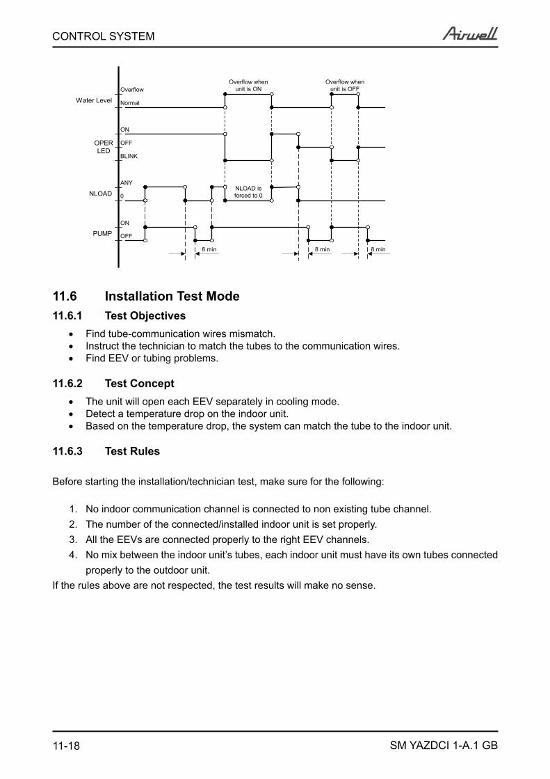
11-18
CONTROL SYSTEM
SM YAZDCI 1-A.1 GB
ANY
0
ON
NLOAD
PUMP OFF
ON
OPERLED
OFF
Overflow
Water Level Normal
BLINK
NLOAD isforced to 0
8 min 8 min
Overflow whenunit is ON
Overflow whenunit is OFF
8 min
11.6 Installation Test Mode11.6.1 Test Objectives
Find tube-communication wires mismatch. Instruct the technician to match the tubes to the communication wires.Find EEV or tubing problems.
11.6.2 Test ConceptThe unit will open each EEV separately in cooling mode.Detect a temperature drop on the indoor unit.Based on the temperature drop, the system can match the tube to the indoor unit.
11.6.3 Test Rules
Before starting the installation/technician test, make sure for the following:
No indoor communication channel is connected to non existing tube channel.1. The number of the connected/installed indoor unit is set properly.2. All the EEVs are connected properly to the right EEV channels.3. No mix between the indoor unit’s tubes, each indoor unit must have its own tubes connected 4. properly to the outdoor unit.
If the rules above are not respected, the test results will make no sense.
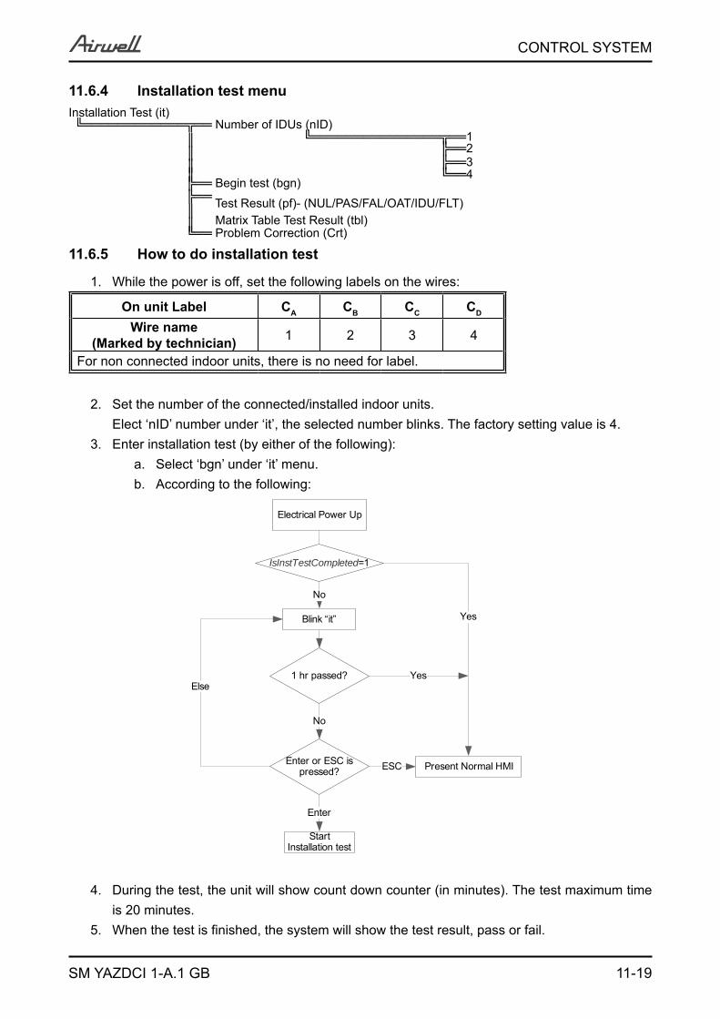
11-19
CONTROL SYSTEM
SM YAZDCI 1-A.1 GB
11.6.4 Installation test menuInstallation Test (it)╚════════════╦══ Number of IDUs (nID)
║ ╚═══════════════╦══1 ║ ╠══2 ║ ╠══3 ║ ╚══4
╠══ Begin test (bgn)╠══
║ Test Result (pf)- (NUL/PAS/FAL/OAT/IDU/FLT)
║ Matrix Table Test Result (tbl) ╚══ Problem Correction (Crt)
11.6.5 How to do installation test
While the power is off, set the following labels on the wires:1.
On unit Label CA CB CC CD
Wire name (Marked by technician) 1 2 3 4
For non connected indoor units, there is no need for label.
Set the number of the connected/installed indoor units.2. Elect ‘nID’ number under ‘it’, the selected number blinks. The factory setting value is 4.Enter installation test (by either of the following):3.
Select ‘bgn’ under ‘it’ menu.a. According to the following:b.
IsInstTestCompleted=1
Electrical Power Up
No
Enter or ESC is pressed?
Blink “it”
Start Installation test
Present Normal HMI
Yes
ESC
Enter
1 hr passed?
No
YesElse
During the test, the unit will show count down counter (in minutes). The test maximum time 4. is 20 minutes. When the test is finished, the system will show the test result, pass or fail.5.
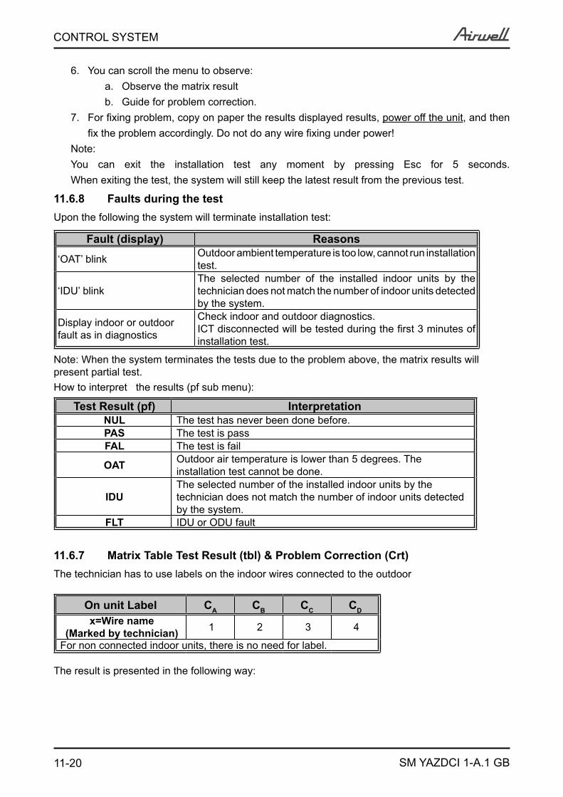
11-20
CONTROL SYSTEM
SM YAZDCI 1-A.1 GB
You can scroll the menu to observe:6. Observe the matrix resulta. Guide for problem correction.b.
For fixing problem, copy on paper the results displayed results, 7. power off the unit, and then fix the problem accordingly. Do not do any wire fixing under power!
Note:You can exit the installation test any moment by pressing Esc for 5 seconds.When exiting the test, the system will still keep the latest result from the previous test.
11.6.8 Faults during the testUpon the following the system will terminate installation test:
Fault (display) Reasons
‘OAT’ blink Outdoor ambient temperature is too low, cannot run installation test.
‘IDU’ blinkThe selected number of the installed indoor units by the technician does not match the number of indoor units detected by the system.
Display indoor or outdoor fault as in diagnostics
Check indoor and outdoor diagnostics.ICT disconnected will be tested during the first 3 minutes of installation test.
Note: When the system terminates the tests due to the problem above, the matrix results will present partial test.How to interpret the results (pf sub menu):
Test Result (pf) InterpretationNUL The test has never been done before.PAS The test is passFAL The test is fail
OAT Outdoor air temperature is lower than 5 degrees. The installation test cannot be done.
IDUThe selected number of the installed indoor units by the technician does not match the number of indoor units detected by the system.
FLT IDU or ODU fault
11.6.7 Matrix Table Test Result (tbl) & Problem Correction (Crt)The technician has to use labels on the indoor wires connected to the outdoor
On unit Label CA CB CC CD
x=Wire name (Marked by technician) 1 2 3 4
For non connected indoor units, there is no need for label.
The result is presented in the following way:
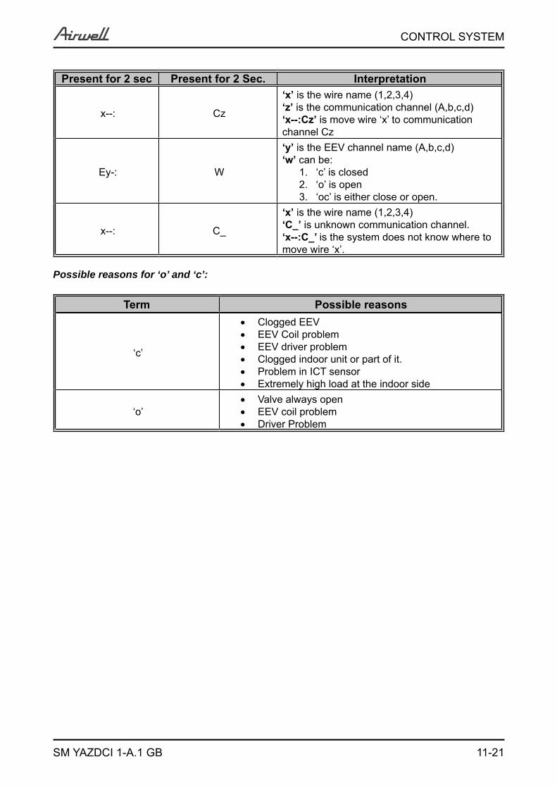
11-21
CONTROL SYSTEM
SM YAZDCI 1-A.1 GB
Present for 2 sec Present for 2 Sec. Interpretation
x--: Cz
‘x’ is the wire name (1,2,3,4)‘z’ is the communication channel (A,b,c,d)‘x--:Cz’ is move wire ‘x’ to communication channel Cz
Ey-: W
‘y’ is the EEV channel name (A,b,c,d)‘w’ can be:
‘c’ is closed1. ‘o’ is open2. ‘oc’ is either close or open.3.
x--: C_
‘x’ is the wire name (1,2,3,4)‘C_’ is unknown communication channel.‘x--:C_’ is the system does not know where to move wire ‘x’.
Possible reasons for ‘o’ and ‘c’:
Term Possible reasons
‘c’
Clogged EEVEEV Coil problemEEV driver problemClogged indoor unit or part of it.Problem in ICT sensorExtremely high load at the indoor side
‘o’Valve always openEEV coil problem Driver Problem
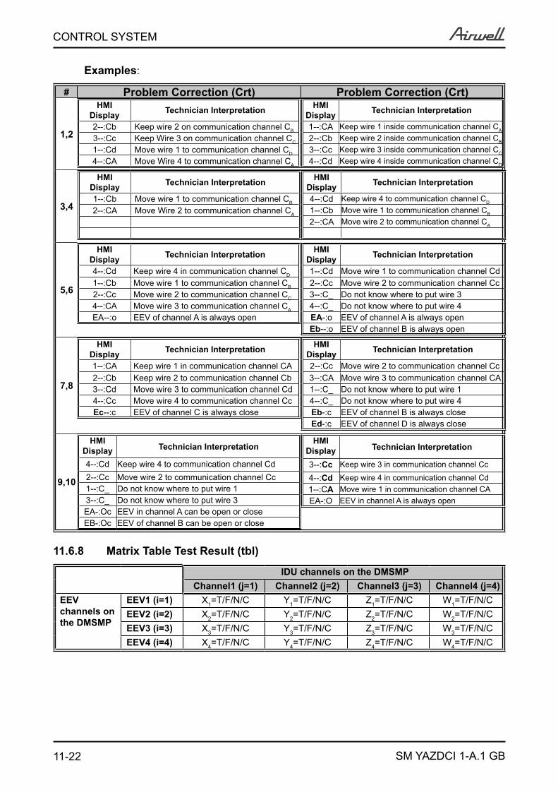
11-22
CONTROL SYSTEM
SM YAZDCI 1-A.1 GB
Examples:
# Problem Correction (Crt) Problem Correction (Crt)
1,2
HMI Display Technician Interpretation
2--:Cb Keep wire 2 on communication channel CB
3--:Cc Keep Wire 3 on communication channel CC
1--:Cd Move wire 1 to communication channel CD
4--:CA Move Wire 4 to communication channel CA
HMI Display Technician Interpretation
1--:CA Keep wire 1 inside communication channel CA
2--:Cb Keep wire 2 inside communication channel CB
3--:Cc Keep wire 3 inside communication channel CC
4--:Cd Keep wire 4 inside communication channel CD
3,4
HMI Display Technician Interpretation
1--:Cb Move wire 1 to communication channel CB
2--:CA Move Wire 2 to communication channel CA
HMI Display Technician Interpretation
4--:Cd Keep wire 4 to communication channel CD
1--:Cb Move wire 1 to communication channel CB
2--:CA Move wire 2 to communication channel CA
5,6
HMI Display Technician Interpretation
4--:Cd Keep wire 4 in communication channel CD
1--:Cb Move wire 1 to communication channel CB
2--:Cc Move wire 2 to communication channel CC
4--:CA Move wire 3 to communication channel CA
EA--:o EEV of channel A is always open
HMI Display Technician Interpretation
1--:Cd Move wire 1 to communication channel Cd2--:Cc Move wire 2 to communication channel Cc3--:C_ Do not know where to put wire 34--:C_ Do not know where to put wire 4EA-:o EEV of channel A is always openEb--:o EEV of channel B is always open
7,8
HMI Display Technician Interpretation
1--:CA Keep wire 1 in communication channel CA2--:Cb Keep wire 2 to communication channel Cb3--:Cd Move wire 3 to communication channel Cd4--:Cc Move wire 4 to communication channel CcEc--:c EEV of channel C is always close
HMI Display Technician Interpretation
2--:Cc Move wire 2 to communication channel Cc3--:CA Move wire 3 to communication channel CA1--:C_ Do not know where to put wire 14--:C_ Do not know where to put wire 4Eb-:c EEV of channel B is always closeEd-:c EEV of channel D is always close
9,10
HMI Display Technician Interpretation
4--:Cd Keep wire 4 to communication channel Cd2--:Cc Move wire 2 to communication channel Cc1--:C_ Do not know where to put wire 13--:C_ Do not know where to put wire 3EA-:Oc EEV in channel A can be open or closeEB-:Oc EEV of channel B can be open or close
HMI Display Technician Interpretation
3--:Cc Keep wire 3 in communication channel Cc
4--:Cd Keep wire 4 in communication channel Cd1--:CA Move wire 1 in communication channel CAEA-:O EEV in channel A is always open
11.6.8 Matrix Table Test Result (tbl)
IDU channels on the DMSMPChannel1 (j=1) Channel2 (j=2) Channel3 (j=3) Channel4 (j=4)
EEV channels on the DMSMP
EEV1 (i=1) X1=T/F/N/C Y1=T/F/N/C Z1=T/F/N/C W1=T/F/N/CEEV2 (i=2) X2=T/F/N/C Y2=T/F/N/C Z2=T/F/N/C W2=T/F/N/CEEV3 (i=3) X3=T/F/N/C Y3=T/F/N/C Z3=T/F/N/C W3=T/F/N/CEEV4 (i=4) X4=T/F/N/C Y4=T/F/N/C Z4=T/F/N/C W4=T/F/N/C
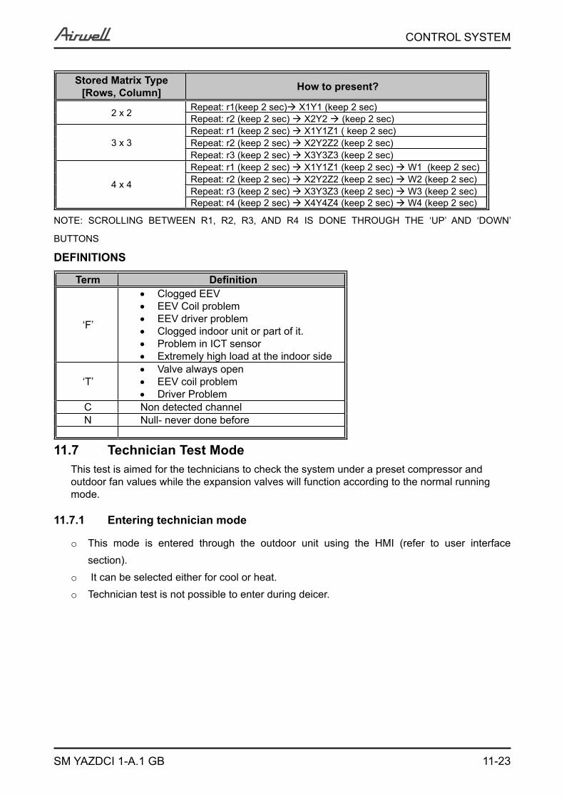
11-23
CONTROL SYSTEM
SM YAZDCI 1-A.1 GB
Stored Matrix Type[Rows, Column] How to present?
2 x 2 Repeat: r1(keep 2 sec) X1Y1 (keep 2 sec)Repeat: r2 (keep 2 sec) X2Y2 (keep 2 sec)
3 x 3Repeat: r1 (keep 2 sec) X1Y1Z1 ( keep 2 sec)Repeat: r2 (keep 2 sec) X2Y2Z2 (keep 2 sec)Repeat: r3 (keep 2 sec) X3Y3Z3 (keep 2 sec)
4 x 4
Repeat: r1 (keep 2 sec) X1Y1Z1 (keep 2 sec) W1 (keep 2 sec)Repeat: r2 (keep 2 sec) X2Y2Z2 (keep 2 sec) W2 (keep 2 sec)Repeat: r3 (keep 2 sec) X3Y3Z3 (keep 2 sec) W3 (keep 2 sec)Repeat: r4 (keep 2 sec) X4Y4Z4 (keep 2 sec) W4 (keep 2 sec)
NOTE: SCROLLING BETWEEN R1, R2, R3, AND R4 IS DONE THROUGH THE ‘UP’ AND ‘DOWN’
BUTTONS DEFINITIONS
Term Definition
‘F’
Clogged EEVEEV Coil problemEEV driver problemClogged indoor unit or part of it.Problem in ICT sensorExtremely high load at the indoor side
‘T’Valve always openEEV coil problem Driver Problem
C Non detected channelN Null- never done before
11.7 Technician Test ModeThis test is aimed for the technicians to check the system under a preset compressor and outdoor fan values while the expansion valves will function according to the normal running mode.
11.7.1 Entering technician mode
This mode is entered through the outdoor unit using the HMI (refer to user interface o
section). It can be selected either for cool or heat.o
Technician test is not possible to enter during deicer.o
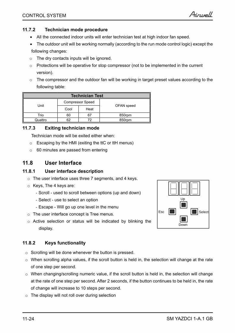
11-24
CONTROL SYSTEM
SM YAZDCI 1-A.1 GB
11.7.2 Technician mode procedureAll the connected indoor units will enter technician test at high indoor fan speed.
The outdoor unit will be working normally (according to the run mode control logic) except the
following changes:The dry contacts inputs will be ignored.o
Protections will be operative for stop compressor (not to be implemented in the current o
version).The compressor and the outdoor fan will be working in target preset values according to the o
following table:
Technician Test
UnitCompressor Speed
OFAN speedCool Heat
Trio 60 67 850rpmQuattro 62 72 850rpm
11.7.3 Exiting technician modeTechnician mode will be exited either when:
Escaping by the HMI (exiting the ttC or ttH menus)o
60 minutes are passed from entering o
11.8 User Interface11.8.1 User interface description
The user interface uses three 7 segments, and 4 keys.o
Keys, The 4 keys are:o
Scroll - used to scroll between options (up and down)- Select - use to select an option- Escape - Will go up one level in the menu-
The user interface concept is Tree menus.o
Active selection or status will be indicated by blinking the o
display.
11.8.2 Keys functionality
Scrolling will be done whenever the button is pressed.o
When scrolling alpha values, if the scroll button is held in, the selection will change at the rate o
of one step per second.When changing/scrolling numeric value, if the scroll button is held in, the selection will change o
at the rate of one step per second. After 2 seconds, if the button continues to be held in, the rate of change will increase to 10 steps per second.The display will not roll over during selectiono
Up
Down
Esc Select
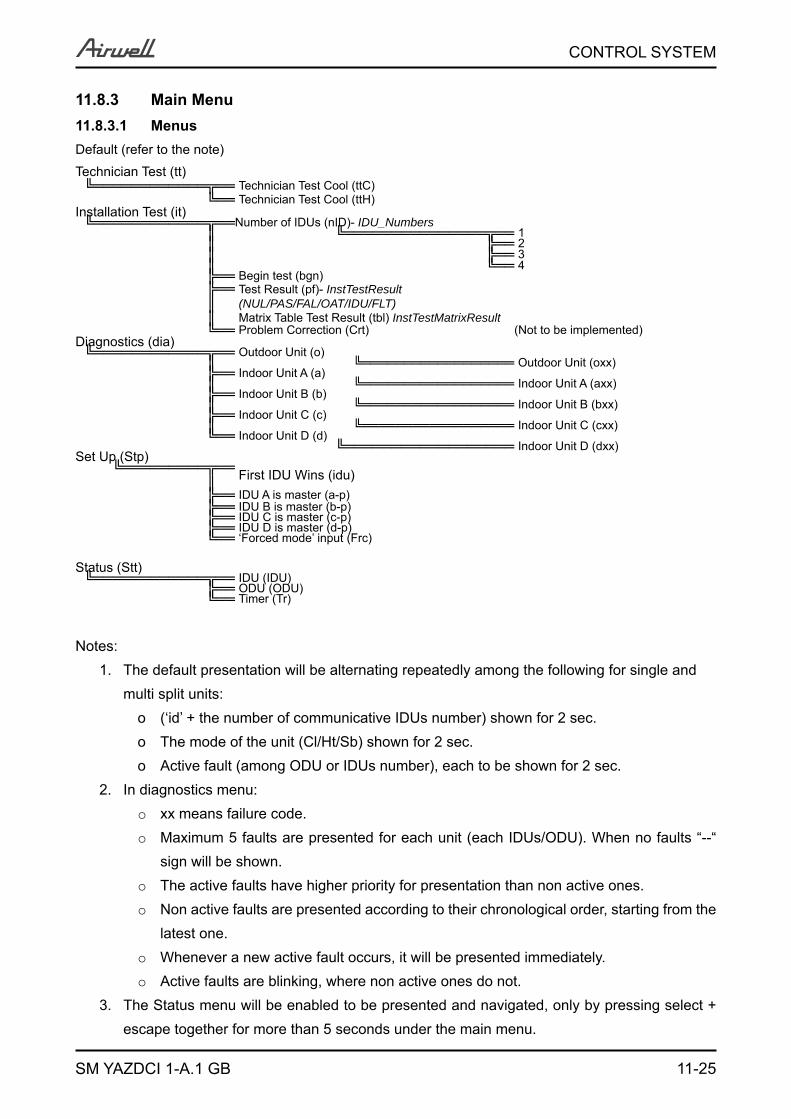
11-25
CONTROL SYSTEM
SM YAZDCI 1-A.1 GB
11.8.3 Main Menu11.8.3.1 MenusDefault (refer to the note)Technician Test (tt)╚════════════╦══ Technician Test Cool (ttC)
╚══ Technician Test Cool (ttH)Installation Test (it)╚════════════╦══Number of IDUs (nID)- IDU_Numbers
║ ╚═══════════════╦══ 1║ ╠══ 2║ ╠══ 3║ ╚══ 4 ╠══ Begin test (bgn)╠══║
Test Result (pf)- InstTestResult(NUL/PAS/FAL/OAT/IDU/FLT)
║ Matrix Table Test Result (tbl) InstTestMatrixResult╚══ Problem Correction (Crt) (Not to be implemented)
Diagnostics (dia)╚════════════╦══ Outdoor Unit (o)
║ ╚══════════════════ Outdoor Unit (oxx)╠══ Indoor Unit A (a)║ ╚══════════════════ Indoor Unit A (axx) ╠══ Indoor Unit B (b)║ ╚══════════════════ Indoor Unit B (bxx) ╠══ Indoor Unit C (c)║ ╚══════════════════ Indoor Unit C (cxx) ╚══ Indoor Unit D (d)
╚══════════════════ Indoor Unit D (dxx) Set Up (Stp)╚═════════╦══
║ First IDU Wins (idu)╠══ IDU A is master (a-p)╠══ IDU B is master (b-p)╠══ IDU C is master (c-p)╠══ IDU D is master (d-p)╚══ ‘Forced mode’ input (Frc)
Status (Stt)╚════════════╦══ IDU (IDU)
╠══ ODU (ODU)╚══ Timer (Tr)
Notes:The default presentation will be alternating repeatedly among the following for single and 1. multi split units:
(‘id’ + the number of communicative IDUs number) shown for 2 sec.o The mode of the unit (Cl/Ht/Sb) shown for 2 sec.o Active fault (among ODU or IDUs number), each to be shown for 2 sec.o
In diagnostics menu:2. xx means failure code. o
Maximum 5 faults are presented for each unit (each IDUs/ODU). When no faults “--“ o
sign will be shown.The active faults have higher priority for presentation than non active ones.o
Non active faults are presented according to their chronological order, starting from the o
latest one.Whenever a new active fault occurs, it will be presented immediately.o
Active faults are blinking, where non active ones do not.o
The Status menu will be enabled to be presented and navigated, only by pressing select + 3. escape together for more than 5 seconds under the main menu.
11-26
CONTROL SYSTEM
SM YAZDCI 1-A.1 GB
Exiting ‘Status’ menu and its sub-menus back to the main menu is done by either pressing 4. escape or after continuous 60 minutes out of any press.Technician Test mode, once is selected, is exited after 60 minutes from entry.5.
6. All the menus, except Status and its sub-menu, Technician Test once selected, are automatically exited to the main menu after 10 continuous minute out of any press.
7. When Technician test cool or heat menus are selected (operative), it will be blinking constantly until, this menu is escaped.
8. When the installation test is begins, the system will show up count down based (refer to the installation test sect. At the end of the installation test, the result will be presented.
9. For the indoor diagnostics, whenever there is no-communication with indoor unit or indoor unit is not detected, ‘no-communication’ will be shown under the relevant indoor unit diagnostics. In addition to the indoor diagnostics, these faults will be also shown as well under the default show.
10. When Alpha and numeric values are combined, they will be separated by dot.
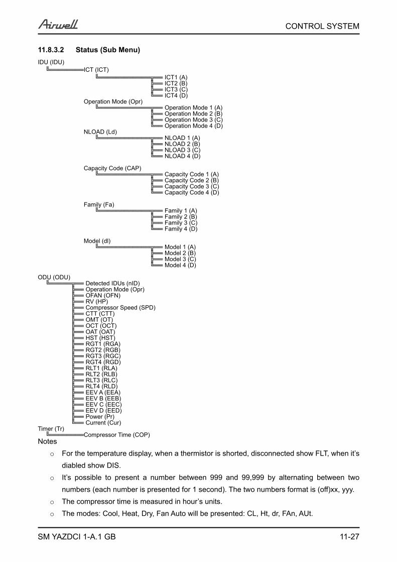
11-27
CONTROL SYSTEM
SM YAZDCI 1-A.1 GB
11.8.3.2 Status (Sub Menu)IDU (IDU)
╚════════ICT (ICT)╚════════════╦══ ICT1 (A)
╠══ ICT2 (B)╠══ ICT3 (C)╚══ ICT4 (D)
Operation Mode (Opr)╚════════════╦══ Operation Mode 1 (A)
╠══ Operation Mode 2 (B)╠══ Operation Mode 3 (C)╚══ Operation Mode 4 (D)
NLOAD (Ld)╚════════════╦══ NLOAD 1 (A)
╠══ NLOAD 2 (B)╠══ NLOAD 3 (C)╚══ NLOAD 4 (D)
Capacity Code (CAP)╚════════════╦══ Capacity Code 1 (A)
╠══ Capacity Code 2 (B)╠══ Capacity Code 3 (C)╚══ Capacity Code 4 (D)
Family (Fa)╚════════════╦══ Family 1 (A)
╠══ Family 2 (B)╠══ Family 3 (C)╚══ Family 4 (D)
Model (dl)╚════════════╦══ Model 1 (A)
╠══ Model 2 (B)╠══ Model 3 (C)╚══ Model 4 (D)
ODU (ODU)╚═════╦══ Detected IDUs (nID)
╠══ Operation Mode (Opr)╠══ OFAN (OFN)╠══ RV (HP)╠══ Compressor Speed (SPD)╠══ CTT (CTT)╠══ OMT (OT)╠══ OCT (OCT)╠══ OAT (OAT)╠══ HST (HST)╠══ RGT1 (RGA)╠══ RGT2 (RGB)╠══ RGT3 (RGC)╠══ RGT4 (RGD)╠══ RLT1 (RLA)╠══ RLT2 (RLB)╠══ RLT3 (RLC)╠══ RLT4 (RLD)╠══ EEV A (EEA)╠══ EEV B (EEB)╠══ EEV C (EEC)╠══ EEV D (EED)╠══ Power (Pr)╚══ Current (Cur)
Timer (Tr)╚════════Compressor Time (COP)
NotesFor the temperature display, when a thermistor is shorted, disconnected show FLT, when it’s o
diabled show DIS.It’s possible to present a number between 999 and 99,999 by alternating between two o
numbers (each number is presented for 1 second). The two numbers format is (off)xx, yyy.The compressor time is measured in hour’s units.o
The modes: Cool, Heat, Dry, Fan Auto will be presented: CL, Ht, dr, FAn, AUt.o
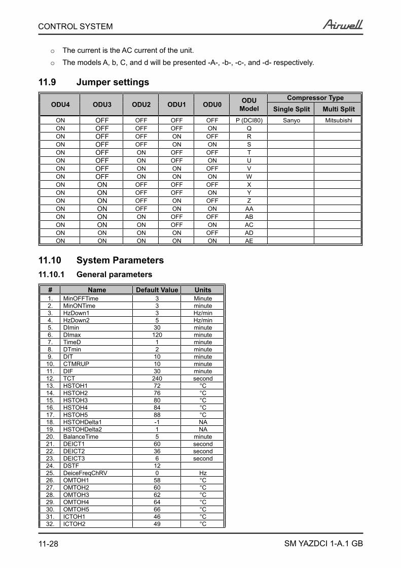
11-28
CONTROL SYSTEM
SM YAZDCI 1-A.1 GB
The current is the AC current of the unit.o
The models A, b, C, and d will be presented -A-, -b-, -c-, and -d- respectively.o
11.9 Jumper settings
ODU4 ODU3 ODU2 ODU1 ODU0 ODU Model
Compressor TypeSingle Split Multi Split
ON OFF OFF OFF OFF P (DCI80) Sanyo MitsubishiON OFF OFF OFF ON QON OFF OFF ON OFF RON OFF OFF ON ON SON OFF ON OFF OFF TON OFF ON OFF ON UON OFF ON ON OFF VON OFF ON ON ON WON ON OFF OFF OFF XON ON OFF OFF ON YON ON OFF ON OFF ZON ON OFF ON ON AAON ON ON OFF OFF ABON ON ON OFF ON ACON ON ON ON OFF ADON ON ON ON ON AE
11.10 System Parameters11.10.1 General parameters
# Name Default Value Units1. MinOFFTime 3 Minute2. MinONTime 3 minute3. HzDown1 3 Hz/min4. HzDown2 5 Hz/min5. DImin 30 minute6. DImax 120 minute7. TimeD 1 minute8. DTmin 2 minute9. DIT 10 minute
10. CTMRUP 10 minute11. DIF 30 minute12. TCT 240 second13. HSTOH1 72 °C14. HSTOH2 76 °C15. HSTOH3 80 °C16. HSTOH4 84 °C17. HSTOH5 88 °C18. HSTOHDelta1 -1 NA19. HSTOHDelta2 1 NA20. BalanceTime 5 minute21. DEICT1 60 second22. DEICT2 36 second23. DEICT3 6 second24. DSTF 1225. DeiceFreqChRV 0 Hz26. OMTOH1 58 °C27. OMTOH2 60 °C28. OMTOH3 62 °C29. OMTOH4 64 °C30. OMTOH5 66 °C31. ICTOH1 46 °C32. ICTOH2 49 °C
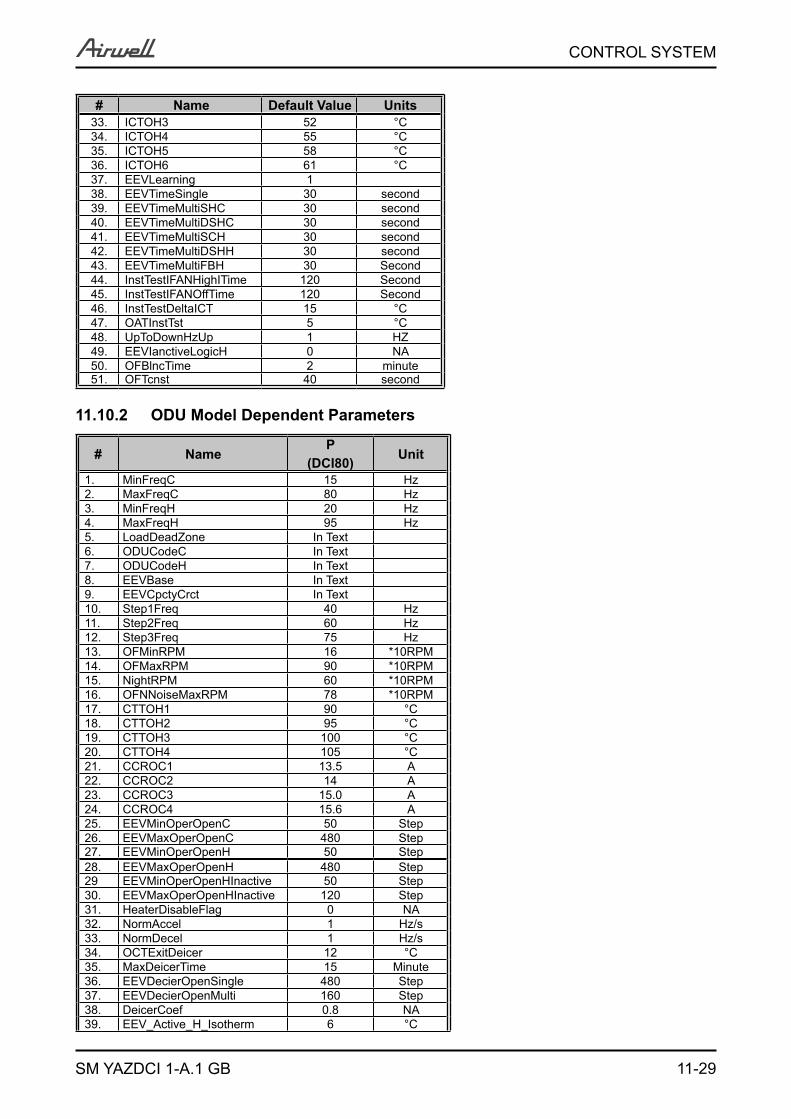
11-29
CONTROL SYSTEM
SM YAZDCI 1-A.1 GB
# Name Default Value Units33. ICTOH3 52 °C34. ICTOH4 55 °C35. ICTOH5 58 °C36. ICTOH6 61 °C37. EEVLearning 138. EEVTimeSingle 30 second39. EEVTimeMultiSHC 30 second40. EEVTimeMultiDSHC 30 second41. EEVTimeMultiSCH 30 second42. EEVTimeMultiDSHH 30 second43. EEVTimeMultiFBH 30 Second44. InstTestIFANHighITime 120 Second45. InstTestIFANOffTime 120 Second46. InstTestDeltaICT 15 °C47. OATInstTst 5 °C48. UpToDownHzUp 1 HZ49. EEVIanctiveLogicH 0 NA50. OFBlncTime 2 minute51. OFTcnst 40 second
11.10.2 ODU Model Dependent Parameters
# NameP
(DCI80) Unit
1. MinFreqC 15 Hz2. MaxFreqC 80 Hz3. MinFreqH 20 Hz4. MaxFreqH 95 Hz5. LoadDeadZone In Text6. ODUCodeC In Text7. ODUCodeH In Text8. EEVBase In Text9. EEVCpctyCrct In Text10. Step1Freq 40 Hz11. Step2Freq 60 Hz12. Step3Freq 75 Hz13. OFMinRPM 16 *10RPM14. OFMaxRPM 90 *10RPM15. NightRPM 60 *10RPM16. OFNNoiseMaxRPM 78 *10RPM17. CTTOH1 90 °C18. CTTOH2 95 °C19. CTTOH3 100 °C20. CTTOH4 105 °C21. CCROC1 13.5 A22. CCROC2 14 A23. CCROC3 15.0 A24. CCROC4 15.6 A25. EEVMinOperOpenC 50 Step26. EEVMaxOperOpenC 480 Step27. EEVMinOperOpenH 50 Step28. EEVMaxOperOpenH 480 Step29 EEVMinOperOpenHInactive 50 Step30. EEVMaxOperOpenHInactive 120 Step31. HeaterDisableFlag 0 NA32. NormAccel 1 Hz/s33. NormDecel 1 Hz/s34. OCTExitDeicer 12 °C35. MaxDeicerTime 15 Minute36. EEVDecierOpenSingle 480 Step37. EEVDecierOpenMulti 160 Step38. DeicerCoef 0.8 NA39. EEV_Active_H_Isotherm 6 °C
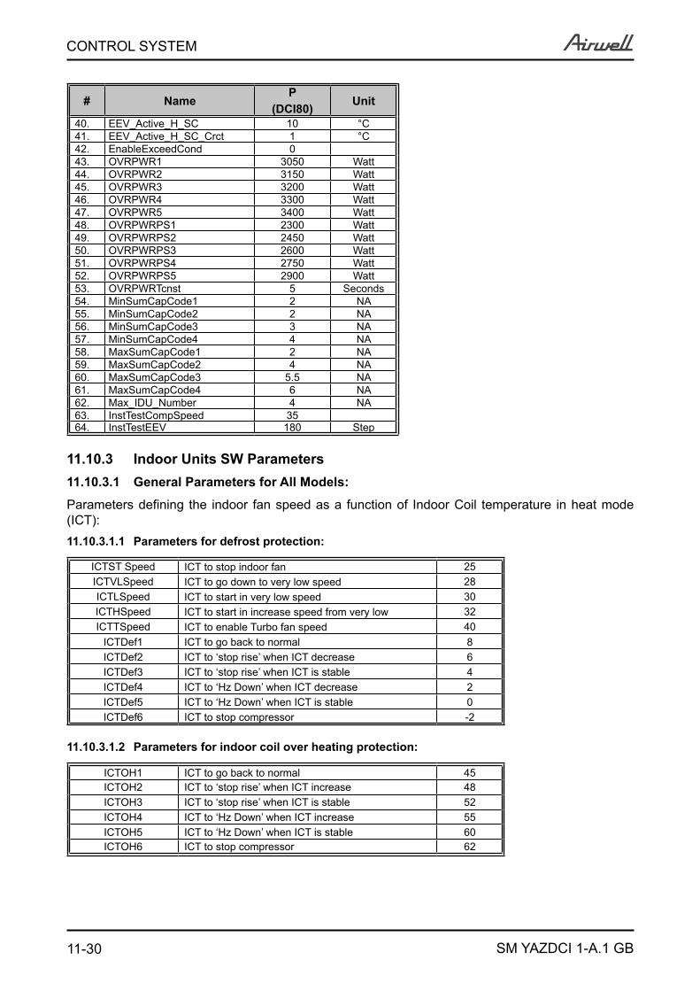
11-30
CONTROL SYSTEM
SM YAZDCI 1-A.1 GB
# NameP
(DCI80) Unit
40. EEV_Active_H_SC 10 °C41. EEV_Active_H_SC_Crct 1 °C42. EnableExceedCond 043. OVRPWR1 3050 Watt44. OVRPWR2 3150 Watt45. OVRPWR3 3200 Watt46. OVRPWR4 3300 Watt47. OVRPWR5 3400 Watt48. OVRPWRPS1 2300 Watt49. OVRPWRPS2 2450 Watt50. OVRPWRPS3 2600 Watt51. OVRPWRPS4 2750 Watt52. OVRPWRPS5 2900 Watt53. OVRPWRTcnst 5 Seconds54. MinSumCapCode1 2 NA55. MinSumCapCode2 2 NA56. MinSumCapCode3 3 NA57. MinSumCapCode4 4 NA58. MaxSumCapCode1 2 NA59. MaxSumCapCode2 4 NA60. MaxSumCapCode3 5.5 NA61. MaxSumCapCode4 6 NA62. Max_IDU_Number 4 NA63. InstTestCompSpeed 3564. InstTestEEV 180 Step
11.10.3 Indoor Units SW Parameters11.10.3.1 General Parameters for All Models:
Parameters defining the indoor fan speed as a function of Indoor Coil temperature in heat mode (ICT):11.10.3.1.1 Parameters for defrost protection:
ICTST Speed ICT to stop indoor fan 25ICTVLSpeed ICT to go down to very low speed 28ICTLSpeed ICT to start in very low speed 30ICTHSpeed ICT to start in increase speed from very low 32ICTTSpeed ICT to enable Turbo fan speed 40
ICTDef1 ICT to go back to normal 8ICTDef2 ICT to ‘stop rise’ when ICT decrease 6ICTDef3 ICT to ‘stop rise’ when ICT is stable 4ICTDef4 ICT to ‘Hz Down’ when ICT decrease 2ICTDef5 ICT to ‘Hz Down’ when ICT is stable 0ICTDef6 ICT to stop compressor -2
11.10.3.1.2 Parameters for indoor coil over heating protection:
ICTOH1 ICT to go back to normal 45ICTOH2 ICT to ‘stop rise’ when ICT increase 48ICTOH3 ICT to ‘stop rise’ when ICT is stable 52ICTOH4 ICT to ‘Hz Down’ when ICT increase 55ICTOH5 ICT to ‘Hz Down’ when ICT is stable 60ICTOH6 ICT to stop compressor 62
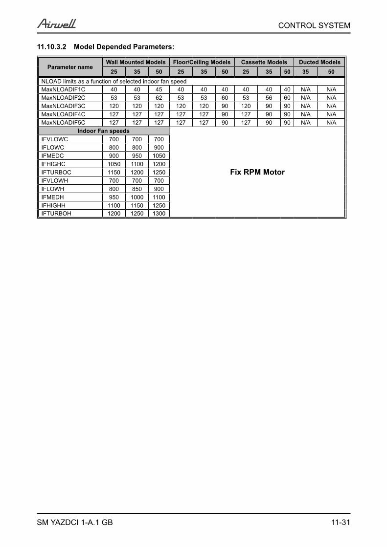
11-31
CONTROL SYSTEM
SM YAZDCI 1-A.1 GB
11.10.3.2 Model Depended Parameters:
Parameter nameWall Mounted Models Floor/Ceiling Models Cassette Models Ducted Models
25 35 50 25 35 50 25 35 50 35 50NLOAD limits as a function of selected indoor fan speedMaxNLOADIF1C 40 40 45 40 40 40 40 40 40 N/A N/AMaxNLOADIF2C 53 53 62 53 53 60 53 56 60 N/A N/AMaxNLOADIF3C 120 120 120 120 120 90 120 90 90 N/A N/AMaxNLOADIF4C 127 127 127 127 127 90 127 90 90 N/A N/AMaxNLOADIF5C 127 127 127 127 127 90 127 90 90 N/A N/A
Indoor Fan speeds
Fix RPM Motor
IFVLOWC 700 700 700IFLOWC 800 800 900IFMEDC 900 950 1050IFHIGHC 1050 1100 1200IFTURBOC 1150 1200 1250IFVLOWH 700 700 700IFLOWH 800 850 900IFMEDH 950 1000 1100IFHIGHH 1100 1150 1250IFTURBOH 1200 1250 1300
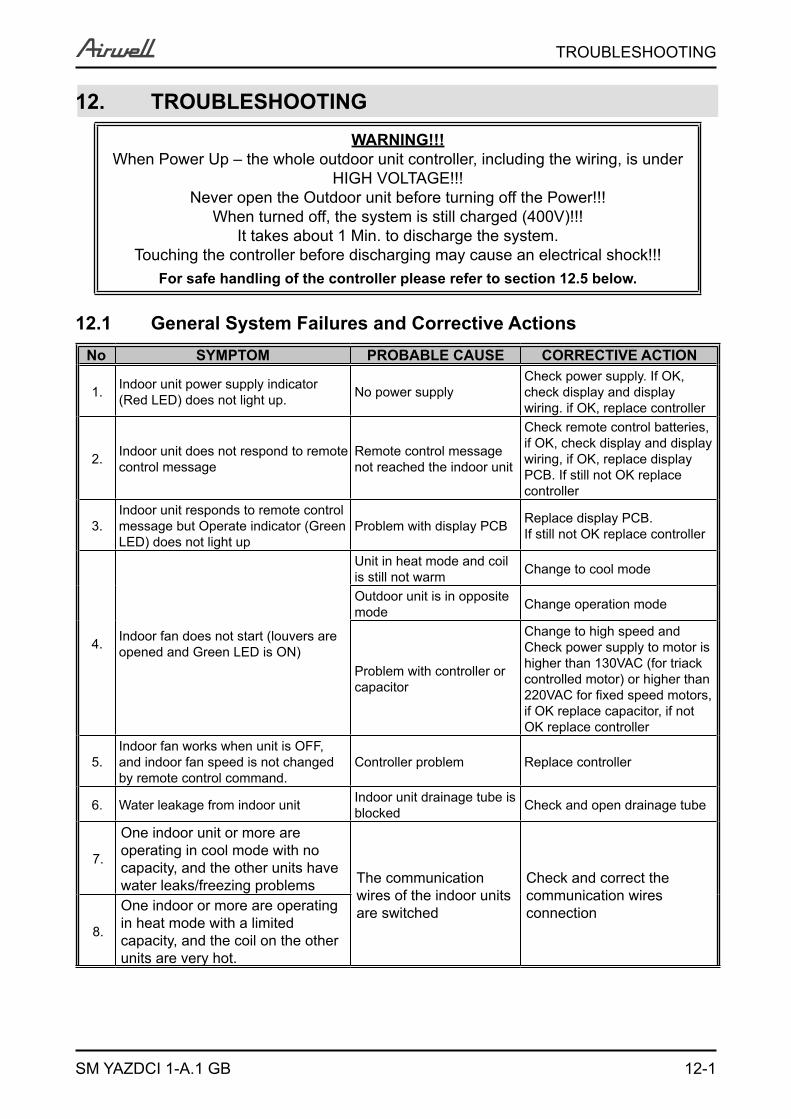
12-1
TROUBLESHOOTING
SM YAZDCI 1-A.1 GB
12. TROUBLESHOOTINGWARNING!!!
When Power Up – the whole outdoor unit controller, including the wiring, is under HIGH VOLTAGE!!!
Never open the Outdoor unit before turning off the Power!!!When turned off, the system is still charged (400V)!!!
It takes about 1 Min. to discharge the system.Touching the controller before discharging may cause an electrical shock!!!
For safe handling of the controller please refer to section 12.5 below.
12.1 General System Failures and Corrective ActionsNo SYMPTOM PROBABLE CAUSE CORRECTIVE ACTION
1. Indoor unit power supply indicator (Red LED) does not light up. No power supply
Check power supply. If OK, check display and display wiring. if OK, replace controller
2. Indoor unit does not respond to remote control message
Remote control message not reached the indoor unit
Check remote control batteries, if OK, check display and display wiring, if OK, replace display PCB. If still not OK replace controller
3.Indoor unit responds to remote control message but Operate indicator (Green LED) does not light up
Problem with display PCB Replace display PCB. If still not OK replace controller
4. Indoor fan does not start (louvers are opened and Green LED is ON)
Unit in heat mode and coil is still not warm Change to cool mode
Outdoor unit is in opposite mode Change operation mode
Problem with controller or capacitor
Change to high speed and Check power supply to motor is higher than 130VAC (for triack controlled motor) or higher than 220VAC for fixed speed motors, if OK replace capacitor, if not OK replace controller
5.Indoor fan works when unit is OFF, and indoor fan speed is not changed by remote control command.
Controller problem Replace controller
6. Water leakage from indoor unit Indoor unit drainage tube is blocked Check and open drainage tube
7.
One indoor unit or more are operating in cool mode with no capacity, and the other units have water leaks/freezing problems The communication
wires of the indoor units are switched
Check and correct the communication wires connection
8.
One indoor or more are operating in heat mode with a limited capacity, and the coil on the other units are very hot.
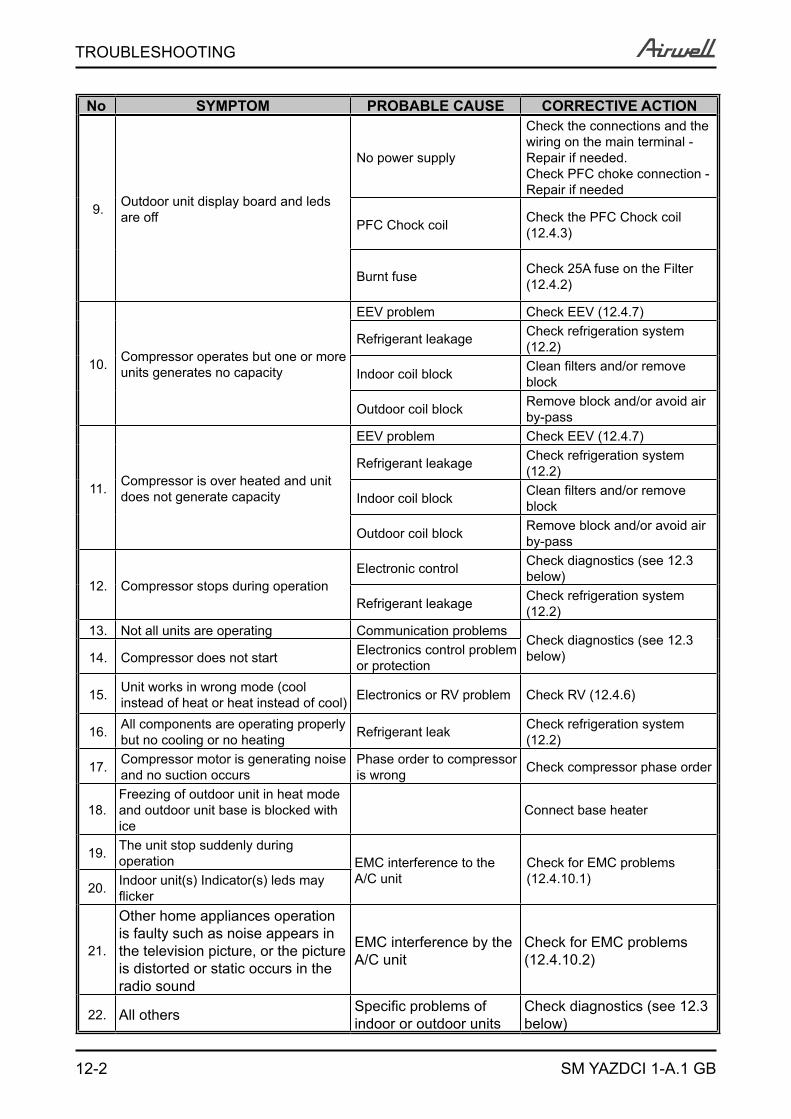
12-2
TROUBLESHOOTING
SM YAZDCI 1-A.1 GB
No SYMPTOM PROBABLE CAUSE CORRECTIVE ACTION
9. Outdoor unit display board and leds are off
No power supply
Check the connections and the wiring on the main terminal - Repair if needed.Check PFC choke connection - Repair if needed
PFC Chock coil Check the PFC Chock coil ( 12.4.3)
Burnt fuse Check 25A fuse on the Filter ( 12.4.2)
10. Compressor operates but one or more units generates no capacity
EEV problem Check EEV ( 12.4.7)
Refrigerant leakage Check refrigeration system ( 12.2)
Indoor coil block Clean filters and/or remove block
Outdoor coil block Remove block and/or avoid air by-pass
11. Compressor is over heated and unit does not generate capacity
EEV problem Check EEV ( 12.4.7)
Refrigerant leakage Check refrigeration system ( 12.2)
Indoor coil block Clean filters and/or remove block
Outdoor coil block Remove block and/or avoid air by-pass
12. Compressor stops during operationElectronic control Check diagnostics (see 12.3
below)
Refrigerant leakage Check refrigeration system ( 12.2)
13. Not all units are operating Communication problemsCheck diagnostics (see 12.3 below)14. Compressor does not start Electronics control problem
or protection
15. Unit works in wrong mode (cool instead of heat or heat instead of cool) Electronics or RV problem Check RV ( 12.4.6)
16. All components are operating properly but no cooling or no heating Refrigerant leak Check refrigeration system
( 12.2)
17. Compressor motor is generating noise and no suction occurs
Phase order to compressor is wrong Check compressor phase order
18.Freezing of outdoor unit in heat mode and outdoor unit base is blocked with ice
Connect base heater
19. The unit stop suddenly during operation EMC interference to the
A/C unitCheck for EMC problems ( 12.4.10.1)
20. Indoor unit(s) Indicator(s) leds may flicker
21.
Other home appliances operation is faulty such as noise appears in the television picture, or the picture is distorted or static occurs in the radio sound
EMC interference by the A/C unit
Check for EMC problems ( 12.4.10.2)
22. All others Specific problems of indoor or outdoor units
Check diagnostics (see 12.3 below)

12-3
TROUBLESHOOTING
SM YAZDCI 1-A.1 GB
12.2 Checking the refrigeration systemChecking system pressures and other thermodynamic measures should be done when system is in technician Mode where the system operates as in fixed settings. The performance curves given in this manual are given for unit performance in Technician mode when high indoor fan speed is selected.For entering technician mode check 11.7.
12.3 Diagnostics12.3.1 Fault Code for Outdoor unitThe last fault occurred in the system will be stored in the EEPROM.
If no fault exist in the system, no fault code will be displayed during normal operation mode.
For single Split units only, when system enters diagnostics mode (through IDU communication), the last fault code will be displayed even if the system has recover from that fault. The last fault will be deleted from the EEPROM after the system has exit diagnostics mode (through IDU communication). The current system operation mode (cool/ heat/ off) will not be changed when system enters diagnostics.The coding method is as follow:STATUS LED is blinking 5 times in 5 seconds, and shut off for the next 5 seconds.FAULT LED will blink during the same 5 seconds according to the following table
No Problem AO 5 4 3 2 11 OCT is shorted/disconnected Yes 0 0 0 0 12 CTT is shorted/disconnected Yes 0 0 0 1 03 HST is shorted/disconnected Yes 0 0 0 1 14 OAT is shorted/disconnected Yes 0 0 1 0 05 OMT is shorted/disconnected Yes 0 0 1 0 16 RGT is shorted/disconnected Yes 0 0 1 1 07 RLT is shorted/disconnected Yes 0 0 1 1 18 Reserved No 0 1 0 0 09 Reserved No 0 1 0 0 1
10 Reserved No 0 1 0 1 011 Compressor IPM Fault / IPM Driver Pin / Compressor Current
Sensor Fault Yes 0 1 0 1 112 Bad EEPROM No 0 1 1 0 013 DC under voltage Yes 0 1 1 0 114 DC over voltage Yes 0 1 1 1 015 AC under voltage/AC over Voltage/Zero Crossing detection Yes 0 1 1 1 116 Mismatch between IDU & ODU models Yes 1 0 0 0 017 No Communication Yes 1 0 0 0 118 System Over Power Yes 1 0 0 1 019 PFC Current sensor Yes 1 0 0 1 120 Heat sink Over Heating No 1 0 1 0 021 Deicing No 1 0 1 0 122 Compressor Over Heating No 1 0 1 1 023 Compressor Over Current No 1 0 1 1 124 No OFAN Feedback Yes 1 1 0 0 025 OFAN IPM fault / OFAN IPM Driver Pin Yes 1 1 0 0 126 Compressor Lock Yes 1 1 0 1 027 Bad Communication No 1 1 0 1 128 Missing ODU configuration Yes 1 1 1 0 029 Undefined ODU Model Yes 1 1 1 0 130 Outdoor/Indoor Coil Overheating No 1 1 1 1 031 Operation conditions are exceeded Yes 1 1 1 1 1
1 – ON, 0 – OFFOnly one code is shown. Order of priority is 1-24. Diagnostics is continuously ON as long power is on.

12-4
TROUBLESHOOTING
SM YAZDCI 1-A.1 GB
11.3.2 Outdoor unit diagnostics and corrective actions
No Fault Name Fault Description Corrective Action
1 OCT bad
Thermistor not connected or damaged Check Thermistor ( 12.4.8)
2 CTT bad3 HST bad4 OAT bad5 OMT bad6 RGT bad7 RLT bad8 Reserved NA NA9 Reserved NA NA
10 Reserved NA NA
11
Compressor IPM Fault / IPM Driver Pin / Compressor Current Sensor Fault
IPM module detect shoot-through current / IPM driver control pin is unconditionally latch to high state /The quiescent reference voltage of sensor resistor is either too high or too low.
Disconnect the the compressor plug and measure between U-V, U-W for resistance using multimeter. Resistance value should be below 1 OHM. If multimeter display high resistance, replace compressor. Make sure the phase sequence of U-V-W is correctly plug into the compressor, othewise replace controller if error is persistent
12 Bad EEPROM Writing to EEPROM is impossible or EEPROM IC is damage
There is no electrinonic corrective action, just replace controller if error is persistent.Note: A/C still be able to operate, but no event logging and mode restore on power up
13 DC under voltageThe capacitor bank DC voltage supply for the compressor is below operable value
Check AC input line voltage RMS value, it should read above 198VAC. If voltage is above 198VAC, and DC under voltage error is continuous display, replace controller.
14 DC over voltage The capacitor bank DC voltage supply for the compressor is too high value
Check AC input line voltage RMS value, it should read below 264VAC. If voltage is below 264VAC, and DC over voltage error is continuously display, replace controller.
15AC under voltage/AC over Voltage/Zero Crossing detection
The AC input supply voltage is below the limit of 198V / The AC input supply voltage is above 264V / The AC line frequency is out of range from 45Hz to 55Hz.
Check AC input line voltage RMS value, it should read in the range of 198VAC – 264VAC. Check AC input line operating frequency, it should be in the range from 45Hz to 55Hz. If error is continuously being display, replace controller.
16 Mismatch between IDU & ODU models
Miss-match between the IDUs connected to port A,B,C or D, or the total capacity code of IDUs is higher than the ODU maximum capacity code
Change configuration if needed.
17 No Communication No signals in lineA,B,C,D Check communication ( 12.4.9)
18 System Over Power Compressor stopped due to over power protection No action required
19 PFC Current sensor Controller cannot detect valid AC line current after compressor start
If error is continuously being display, replace controller.
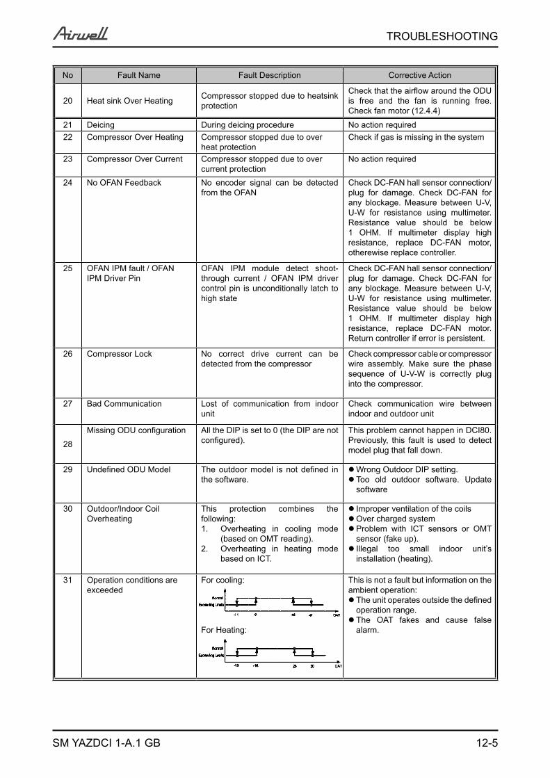
12-5
TROUBLESHOOTING
SM YAZDCI 1-A.1 GB
No Fault Name Fault Description Corrective Action
20 Heat sink Over Heating Compressor stopped due to heatsink protection
Check that the airflow around the ODU is free and the fan is running free. Check fan motor ( 12.4.4)
21 Deicing During deicing procedure No action required22 Compressor Over Heating Compressor stopped due to over
heat protectionCheck if gas is missing in the system
23 Compressor Over Current Compressor stopped due to over current protection
No action required
24 No OFAN Feedback No encoder signal can be detected from the OFAN
Check DC-FAN hall sensor connection/plug for damage. Check DC-FAN for any blockage. Measure between U-V, U-W for resistance using multimeter. Resistance value should be below 1 OHM. If multimeter display high resistance, replace DC-FAN motor, otherewise replace controller.
25 OFAN IPM fault / OFAN IPM Driver Pin
OFAN IPM module detect shoot-through current / OFAN IPM driver control pin is unconditionally latch to high state
Check DC-FAN hall sensor connection/plug for damage. Check DC-FAN for any blockage. Measure between U-V, U-W for resistance using multimeter. Resistance value should be below 1 OHM. If multimeter display high resistance, replace DC-FAN motor. Return controller if error is persistent.
26 Compressor Lock No correct drive current can be detected from the compressor
Check compressor cable or compressor wire assembly. Make sure the phase sequence of U-V-W is correctly plug into the compressor.
27 Bad Communication Lost of communication from indoor unit
Check communication wire between indoor and outdoor unit
28
Missing ODU configuration All the DIP is set to 0 (the DIP are not configured).
This problem cannot happen in DCI80. Previously, this fault is used to detect model plug that fall down.
29 Undefined ODU Model The outdoor model is not defined in the software.
Wrong Outdoor DIP setting. Too old outdoor software. Update software
30 Outdoor/Indoor Coil Overheating
This protection combines the following:
Overheating in cooling mode 1. (based on OMT reading). Overheating in heating mode 2. based on ICT.
Improper ventilation of the coilsOver charged systemProblem with ICT sensors or OMT sensor (fake up).Illegal too small indoor unit’s installation (heating).
31 Operation conditions are exceeded
For cooling:
For Heating:
This is not a fault but information on the ambient operation:
The unit operates outside the defined operation range.The OAT fakes and cause false alarm.
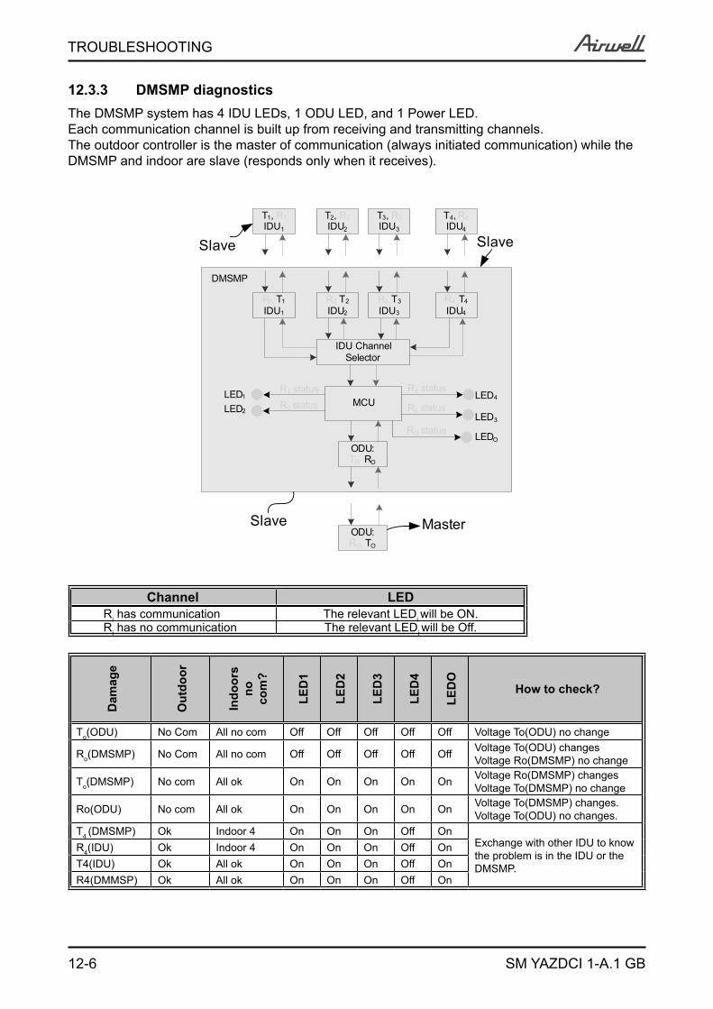
12-6
TROUBLESHOOTING
SM YAZDCI 1-A.1 GB
12.3.3 DMSMP diagnosticsThe DMSMP system has 4 IDU LEDs, 1 ODU LED, and 1 Power LED.Each communication channel is built up from receiving and transmitting channels.The outdoor controller is the master of communication (always initiated communication) while the DMSMP and indoor are slave (responds only when it receives).
R4, T4
IDU4
ODU:TO, RO
IDU Channel Selector
MCUR4 status
R3 status
R1 statusR2 status
R3, T3
IDU3
R2, T2
IDU2
R1, T1
IDU1
RO status
DMSMP
LED4
LED3
LEDO
LED1
LED2
T4, R4IDU4
T3, R3IDU3
T2, R2IDU2
T1, R1IDU1
ODU:RO, TO
MasterSlave
SlaveSlave
Channel LEDRi has communication The relevant LEDi will be ON.Ri has no communication The relevant LEDi will be Off.
Dam
age
Out
door
Indo
ors
no
com
?
LED
1
LED
2
LED
3
LED
4
LED
O
How to check?
To(ODU) No Com All no com Off Off Off Off Off Voltage To(ODU) no change
Ro(DMSMP) No Com All no com Off Off Off Off Off Voltage To(ODU) changesVoltage Ro(DMSMP) no change
To(DMSMP) No com All ok On On On On On Voltage Ro(DMSMP) changesVoltage To(DMSMP) no change
Ro(ODU) No com All ok On On On On On Voltage To(DMSMP) changes.Voltage To(ODU) no changes.
T4 (DMSMP) Ok Indoor 4 On On On Off OnExchange with other IDU to know the problem is in the IDU or the DMSMP.
R4(IDU) Ok Indoor 4 On On On Off OnT4(IDU) Ok All ok On On On Off OnR4(DMMSP) Ok All ok On On On Off On

12-7
TROUBLESHOOTING
SM YAZDCI 1-A.1 GB
12.3.4 Fault Code for Indoor unitPressing Mode button for long will activate diagnostic mode by the acknowledgment of 3 short beeps and lighting of COOL and HEAT LED’s.When Indoor diagnostics is displayed, all four LED’s (STBY, Operate, Filter, TMR) are on. Entering diagnostics in STBY mode allows only viewing of status (fault-display).In diagnostic mode, system problems / information will be indicated by blinking of Heat & Cool LED’s.The coding method will be as follows: Heat led will blink 5 times in 5 seconds, and then will be shut off for the next 5 seconds. Cool Led will blink during the same 5 seconds according to the following table:
No Fault Name 5 4 3 2 11 RT-1 is disconnected 0 0 0 0 12 RT-1 is shorted 0 0 0 1 03 RT-2 is disconnected 0 0 0 1 14 RT-2 is shorted 0 0 1 0 0… Reserved 0 0 1 0 17 Communication mismatch 0 0 1 1 18 No Communication 0 1 0 0 09 No Encoder 0 1 0 0 1
10 Reserved 0 1 0 1 011 Outdoor Unit Fault 0 1 0 1 1… Reserved17 Defrost protection 1 0 0 0 118 Deicing Protection 1 0 0 1 019 Outdoor Unit Protection 1 0 0 1 120 Indoor Coil HP Protection 1 0 1 0 0
21 Overflow Protection 1 0 1 0 1… Reserved24 EEPROM Not Updated 1 1 0 0 025 Bad EEPROM 1 1 0 0 126 Bad Communication 1 1 0 1 027 Using EEPROM data 1 1 0 1 128 Model A 1 1 1 0 029 Model B 1 1 1 0 130 Model C 1 1 1 1 031 Model D 1 1 1 1 1
1 - ON, 0 - OFFOnly one code is shown. Order of priority is lower to the higher number. Diagnostics is continuously ON as long power is on.
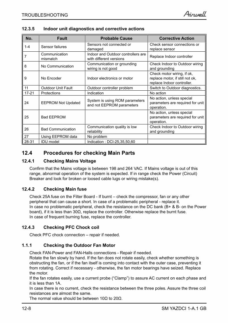
12-8
TROUBLESHOOTING
SM YAZDCI 1-A.1 GB
12.3.5 Indoor unit diagnostics and corrective actions
No. Fault Probable Cause Corrective Action
1-4 Sensor failures Sensors not connected or damaged
Check sensor connections or replace sensor
7 Communication mismatch
Indoor and Outdoor controllers are with different versions Replace Indoor controller
8 No Communication Communication or grounding wiring is not good
Check Indoor to Outdoor wiring and grounding
9 No Encoder Indoor electronics or motorCheck motor wiring, if ok, replace motor, if still not ok, replace Indoor controller.
11 Outdoor Unit Fault Outdoor controller problem Switch to Outdoor diagnostics.17-21 Protections Indication No action
24 EEPROM Not Updated System is using ROM parameters and not EEPROM parameters
No action, unless special parameters are required for unit operation.
25 Bad EEPROMNo action, unless special parameters are required for unit operation.
26 Bad Communication Communication quality is low reliability
Check Indoor to Outdoor wiring and grounding
27 Using EEPROM data No problem28-31 IDU model Indication : DCI-25,35,50,60
12.4 Procedures for checking Main Parts12.4.1 Checking Mains Voltage
Confirm that the Mains voltage is between 198 and 264 VAC. If Mains voltage is out of this range, abnormal operation of the system is expected. If in range check the Power (Circuit) Breaker and look for broken or loosed cable lugs or wiring mistake(s).
12.4.2 Checking Main fuse Check 25A fuse on the Filter Board - If burnt – check the compressor, fan or any other peripheral that can cause a short. In case of a problematic peripheral - replace it. In case no problematic peripheral, check the resistance on the DC bank (B+ & B- on the Power board), if it is less than 30Ω, replace the controller. Otherwise replace the burnt fuse. In case of frequent burning fuse, replace the controller.
12.4.3 Checking PFC Chock coil Check PFC chock connection – repair if needed.
Checking the Outdoor Fan Motor1.1.1 Check FAN-Power and FAN-Halls connections - Repair if needed.Rotate the fan slowly by hand. If the fan does not rotate easily, check whether something is obstructing the fan, or if the fan itself is coming into contact with the outer case, preventing it from rotating. Correct if necessary - otherwise, the fan motor bearings have seized. Replace the motor.If the fan rotates easily, use a current probe (“Clamp”) to assure AC current on each phase and it is less than 1A. In case there is no current, check the resistance between the three poles. Assure the three coil resistances are almost the same. The normal value should be between 10Ω to 20Ω.
12-9
TROUBLESHOOTING
SM YAZDCI 1-A.1 GB
Change to Stand-by or Power OFF and re-start - If the fault is still active - replace controller.
12.4.5 aaChecking the CompressorCheck Compressor connections - Repair if needed.Use a current probe (“Clamp”) to assure that there is an AC current on each phase – no more than 15A. In case there is no current, check the resistance between the three poles. Assure the three coil resistances are almost the same (between 0.8Ω to 1.5Ω).Change to Stand-by or Power OFF and re-start - If the fault is still “Active” - replace controller.
12.4.6 Checking the Reverse Valve (RV)The RV has two parts, Solonoid and valve. Solonoid - Running in heating mode, check the voltage between two pins of reverse valve connector, normal voltage is 230VAC. if no power supply to RV, Check RV operation with direct 230VAC power supply, if OK, replace outdoor controller.Valve - if RV solonoid is OK (as above) but still no heating operation while compressor is On, replace the valve.
12.4.7 Checking the electrical expansion valve (EEV)The EEV has two parts, drive and valve. When Outdoor unit is powered on, EEV shall run and have click and vibration. For assuring the problem is of the EEV parts, perform the installation test check( 11.6) and if fails and no other indications in the diagnostics, than the problem is with the EEV (one or more).Drive - a step motor; ringed on the valve. Check the drive voltage, should be12VDC.Valve – if drive is OK (as above) but still the indoor unit perform no conditioning replace the valve (no need to take out the refrigerant, just pump down and shut off the main valves).
12.4.8 Checking the thermistorsCheck Thermistor connections and wiring - Repair if needed.Check Thermistor resistance – between 0ºC and 40ºC should be between 35KΩ and 5KΩ.
12.4.9 Checking the communicationChange to Stand-by or Power OFF and re-start - If the fault is still “Active” check Indoor to Outdoor Communication wiring and grounding connections (should be less than 2.0Ω) - Repair if needed.If IDU failure – replace IDU controller that does not respond.If ODU failure – replace ODU.
12.4.10 Checking for electromagnetic interferance (EMC problems)
12.4.10.1 EMC troubles to the A/C unit
Locations most susceptible to noise :1. Locations near broadcast stations where there are strong electromagnetic waves.2. Locations near amateur radio (short wave) stations.3. Locations near electronic sewing machines and arc-welding machines.Trouble :Either of the following trouble may occur:1. The unit may stop suddenly during operation.2. Indicator lamps may flicker
12-10
TROUBLESHOOTING
SM YAZDCI 1-A.1 GB
Correction :The fundamental concept is to make the system less susceptible to noise (insulate for noise or distance from the noise source):1. Use shielded wires.2. Move unit away from the noise source.
12.4.10.2 EMC troubles to near by home appliances
Locations most susceptible to noise :1. A television or radio is located near the A/C and A/C wiring.2. The antenna cable for a television or radio is located close to the A/C and A/C wiring. 3. Locations where television and radio signals are weak.Trouble :1. Noise appears in the television picture, or the picture is distorted.2. Static occurs in the radio sound.Correction1. Select a separate power source.2. Keep the A/C and A/C wiring at least 1 meter away from wireless devices and antenna cables.3. Change the wireless device’s antenna to a high sensitivity antenna.4. Change the antenna cable to a BS coaxial cable.5. Use a noise filter (for the wireless device).6. Use a signal booster.
12.5 Precaution, Advise and Notice Items12.5.1 High voltage in Outdoor unit controller
Whole controller, including the wires, connected to the Outdoor unit controller may have the potential hazard voltage when power is on. Touching the Outdoor unit controller may cause an electrical shock.Advise: Don’t touch the naked lead wire and don’t insert finger, conductor or anything else into the controller when power is on.
12.5.2 Charged CapacitorsThree large-capacity electrolytic capacitors are used in the Outdoor unit controller. Therefore, charging voltage (380VDC) remains after power down. Discharging takes about one minute after turned off. Touching the Outdoor unit controller before discharging may cause an electrical shock. When open the Outdoor unit controller cover, don’t touch the soldering pin by hand or by any conductive material.
Advise:Open the Outdoor unit controller cover only after one minute from power off. Measure the electrolytic capacitors voltage before farther checking controller.
Additional advises
When disassemble the controller or the front panel, turn off the power supply. When connecting or disconnecting the connectors on the PCB, hold the whole housing, don’t pull the wire.There are sharp fringes and sting on shell. Use gloves when disassemble the A/C units.
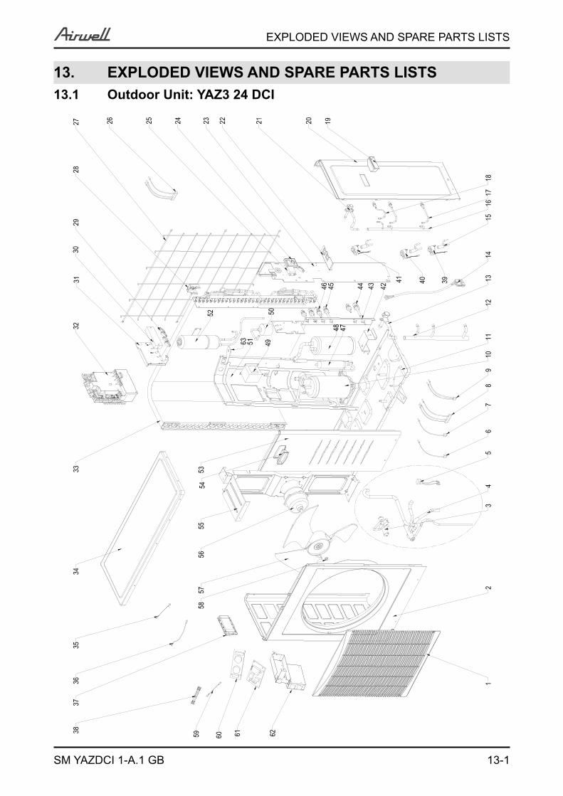
13-1
EXPLODED VIEWS AND SPARE PARTS LISTS
SM YAZDCI 1-A.1 GB
13. EXPLODED VIEWS AND SPARE PARTS LISTS13.1 Outdoor Unit: YAZ3 24 DCI
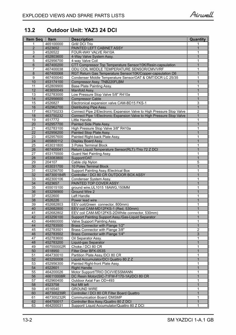
13-2
EXPLODED VIEWS AND SPARE PARTS LISTS
SM YAZDCI 1-A.1 GB
13.2 Outdoor Unit: YAZ3 24 DCIItem Seq Item Description Quantity
1 465100000 Grill/ DCI Trio 12 4523652 PAINTED LEFT CABINET ASSY 13 4526522 FOUR-WAY VALVE R410A 14 452803600 4-Way Valve System Assy. 15 452956700 4-way Valve Coil 16 467400200 CTT Compressor Top Temperature Sensor/10K/Resin-capsulation 17 467400038 ODU COIL MIDDLE TEMPERATURE SENSOR/CMV/VRF 18 467400068 RGT Return Gas Temperature Sensor/10K/Copper-capsulation Ω6 19 467400040 Condenser Middle Temperature Sensor/OAT & OMT/DCR LC 25/35 1
10 453174100 Compressor Assy. TNB220FLBM 111 452809900 Base Plate Painting Assy. 112 463650049 Manifold Assy. 113 452783000 Low Pressure Stop Valve 5/8" R410a 114 452956600 Compressor Cable 115 4526827 Electronical expansion valve CAM-BD15 FKS-1 316 452962700 Distributing Pipe Assy. 117 463750233 Connect Pipe 2/Electronic Expansion Valve to High Pressure Stop Valve 218 463750232 Connect Pipe 1/Electronic Expansion Valve to High Pressure Stop Valve 119 4517772 Little Handle 120 452957700 Painted Side Plate Assy. 121 452783100 High Pressure Stop Valve 3/8" R410a 122 452956200 Painted Stop Plate Assy. 123 452957600 Painted Right-back Plate Assy. 124 465800112 Display Board Assy. 125 453031800 3 Poles Terminal Block 126 467400041 Return Liquid Temperature Sensor(RLT) /Trio 72 Z DCI 127 453175500 Guard Net Painting Assy. 128 453083800 Support/OAT 129 204107 Cable clip Nylon 530 453031700 10 Poles Terninal Block 131 453256700 Support Painting Assy./Electrical Box 132 467300184R Controller / DCI 80 CR OUTDOOR BOX ASSY 133 462300106 Condenser System Assy. 134 4523657 PAINTED TOP COVER ASSY 135 455015100 ground wire,UL1015 18AWG,150MM 136 453256900 Ground Wire 2 137 4522600 Left Handle 138 4526226 Power lead wire 139 452682803 EEV coil(Green connector, 800mm) 140 452682800 EEV coil CAM-MD12FKS-1 (Red, 530mm) 141 452682802 EEV coil CAM-MD12FKS-2ΩWhite connector, 530mm) 142 453256100 Support Painting Support Assy./Gas-Liquid Separator 143 464860000 Valve Support Painting Assy. 144 452783500 Brass Connector with Flange 1/2" 145 452783501 Brass Connector with Flange 3/8" 246 452783502 Brass Connector with Flange 1/4" 347 452783600 Oil Separator Assy. 148 452783200 Liquid-gas Separator 149 467550002R Choke / DCI 80 CR 150 4518950 Filter Drier BFK-053S 151 464730010 Partition Plate Assy./DCI 80 CR 152 463250008 Liquid Accumulator/DCI Quattro 80 Z Z 153 452956300 Painted Right-front Plate Assy. 154 4522601 Right Handle 155 464200026 Motor Support/TRIO DCI/VIESSMANN 156 466110008R DC Resin Motor(SIC-71FW-F170-1A)/DCI 80 CR 157 452960400 Outdoor Axial Fan OD=493 158 4523758 Nut M8 left 159 4516540 GROUND WIRE 160 467300239R Controller / DCI 80 CR Filter Board Quattro 161 467300232R Communication Board /DMSMP 162 464750017 Controller Box Assy./Quattro 80 Z DCI 163 464200031 Support/ Liquid Accumulator/Quattro 80 Z DCI 1
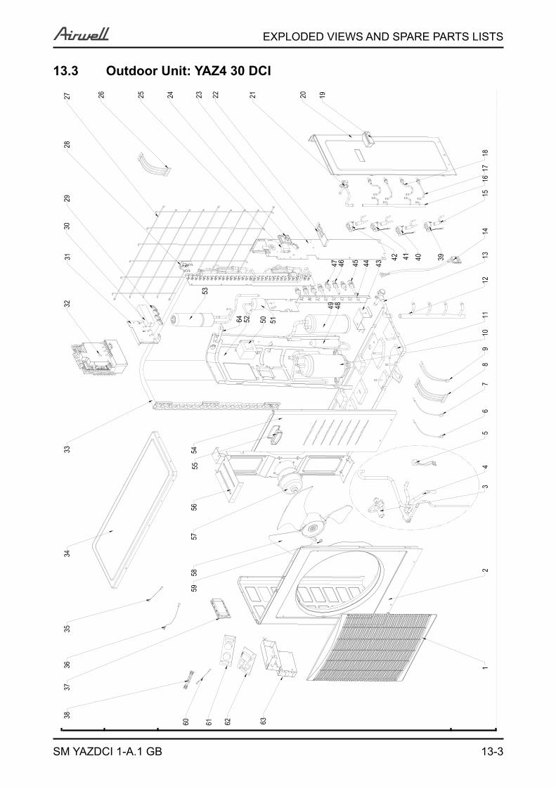
13-3
EXPLODED VIEWS AND SPARE PARTS LISTS
SM YAZDCI 1-A.1 GB
13.3 Outdoor Unit: YAZ4 30 DCI
No. P/N Part Name Quantity 1 4522604 Outlet Grid 12 4523652 Painted Left Cabinet Assy. 13 4526522 4-way Vavle R410a 14 452803600 4-way Valve System Assy. 15 452956700 4-way Valve Coil 16 452966200 Compressor Top Thermistor(CTT) 17 452677601 Outdoor Coil Thermistor(OCT) 18 467400000 Return Gas Thermistor(RGT) 19 452956500 Outdoor Coil Sensor(OMT) 1
10 453174100 Compressor Assy. TNB220FLBM 111 452809900 Base Plate Painting Assy. 112 452962800 Manifold Assy. 113 452783000 Low Pressure Stop Valve 5/8 R410a " 114 452956600 Compressor Cable 115 4526827 Electronical Expansion Valve CAM-BD15 FKS-1 316 452962700 Distributing Pipe Assy. 117 452805100 Connect Pipe 2/Electronic Expansion Valve to High Pressure Stop Valve 218 452803000 Connect Pipe 1/Electronic Expansion Valve to High Pressure Stop Valve 119 4517772 Little Handle 120 452957700 Painted Side Plate Assy. 121 452783100 High Pressure Stop Vavle 3/8 R410a " 122 452956200 Painted Stop Plate Assy. 123 452957600 Painted Right-back Plate Assy. 124 467300005 Display Board Assy. 125 453031800 3 Poles Terminal Block 126 4526774 Outdoor Air Thermistor(OAT) 127 453175500 Guard Net Painting Assy. 128 453083800 Support/OAT 129 204107 Cable Clip Nylon 530 453031700 10 Poles Terminal Block 131 453256700 Support Painting Assy./Electrical Box 132 452956100 DCI Outdoor Controller 3.1kW 133 452802500 Condensor System Assy. 134 4523657 Painted Top Cover Assy. 135 453256800 Ground Wire 1 136 453256900 Ground Wire 2 137 4522600 Left Handle 138 4526226 Power Lead Wire 139 452682803 EEV Coil(Green Connector 800mm) 140 452682800 EEV Coil(Red Connector 530mm) 141 452682802 EEV Coil(White Connector 530mm) 142 453256100 Support Painting Assy./Gas-Liquid Seperator 143 464860000 Valve Support Painting Assy. 144 452783500 Brass Connector With Flange 1/2 " 145 452783501 Brass Connector With Flange 3/8 " 246 452783502 Brass Connector With Flange 1/4 " 347 452783600 Oil Seperator Assy. 148 452783200 Gas-Liquid Seperator 149 453256000 Chock Assy. 150 4518950 Filter Drier BFK-053S 151 452957800 Partition Assy. 152 452783300 Liquid Accumulator 153 452956300 Painted Right-Front Plate Assy. 154 4522601 Right Handle 155 452888500 Motor Support 156 452855600 DC Resin Motor(EHD80A90EC /SIC-71FW-F170-1) 157 452960400 Outdoor Fan 158 4523758 Nut M8 Left 1

13-4
EXPLODED VIEWS AND SPARE PARTS LISTS
SM YAZDCI 1-A.1 GB
13.4 Outdoor Unit: YAZ4 30 DCIItem Seq Component Item Description Quantity
1 465100000 Grill/ DCI Trio 12 4523652 PAINTED LEFT CABINET ASSY 13 4526522 FOUR-WAY VALVE R410A 14 452803600 4-Way Valve System Assy. 15 452956700 4-way Valve Coil 16 467400200 CTT Compressor Top Temperature Sensor/10K/Resin-capsulation 17 467400038 ODU COIL MIDDLE TEMPERATURE SENSOR/CMV/VRF 18 467400067 RGT Return Gas Temperature Sensor/10K/Copper-capsulation 6 19 467400040 Condenser Middle Temperature Sensor/OAT & OMT/DCR LC 25/35 1
10 453174100 Compressor Assy. TNB220FLBM 111 452809900 Base Plate Painting Assy. 112 463650048 Manifold Assy. 113 452783000 Low Pressure Stop Valve 5/8" R410a 114 452956600 Compressor Cable 115 4526827 Electronical expansion valve CAM-BD15 FKS-1 416 452805000 Distributing Pipe Assy. 117 463750233 Connect Pipe 2/Electronic Expansion Valve to High Pressure Stop Valve 218 463750232 Connect Pipe 1/Electronic Expansion Valve to High Pressure Stop Valve 219 4517772 Little Handle 120 452957700 Painted Side Plate Assy. 121 452783100 High Pressure Stop Valve 3/8" R410a 122 452956200 Painted Stop Plate Assy. 123 452957600 Painted Right-back Plate Assy. 124 465800112 Display Board Assy. 125 453031800 3 Poles Terminal Block 126 467400042 Return Liquid Temperature Sensor(RLT) /Quattro 80 Z DCI 127 453175500 Guard Net Painting Assy. 128 453083800 Support/OAT 129 204107 Cable clip Nylon 530 453031700 10 Poles Terninal Block 131 453256700 Support Painting Assy./Electrical Box 132 467300184R Controller / DCI 80 CR OUTDOOR BOX ASSY 133 462300106 Condenser System Assy. 134 4523657 PAINTED TOP COVER ASSY 135 455015100 ground wire,UL1015 18AWG,150MM 136 453256900 Ground Wire 2 137 4522600 Left Handle 138 4526226 Power lead wire 139 452682803 EEV coil(Green connector, 800mm) 140 452682801 EEV Coil (Yellow,700mm) 141 452682800 EEV coil CAM-MD12FKS-1 (Red, 530mm) 142 452682802 EEV coil CAM-MD12FKS-2 White connector, 530mm) 143 453256100 Support Painting Support Assy./Gas-Liquid Separator 144 452811100 Valve Support Painting Assy. 145 452783500 Brass Connector with Flange 1/2" 146 452783501 Brass Connector with Flange 3/8" 347 452783502 Brass Connector with Flange 1/4" 448 452783600 Oil Separator Assy. 149 452783200 Liquid-gas Separator 150 467550002R Choke / DCI 80 CR 151 4518950 Filter Drier BFK-053S 152 464730010 Partition Plate Assy./DCI 80 CR 153 463250008 Liquid Accumulator/DCI Quattro 80 Z Z 154 452956300 Painted Right-front Plate Assy. 155 4522601 Right Handle 156 464200026 Motor Support/TRIO DCI/VIESSMANN 157 466110008R DC Resin Motor(SIC-71FW-F170-1A)/DCI 80 CR 158 452960400 Outdoor Axial Fan OD=493 159 4523758 Nut M8 left 160 4516540 GROUND WIRE 161 467300239R Controller / DCI 80 CR Filter Board Quattro 162 467300232R Communication Board /DMSMP 163 464750017 Controller Box Assy./Quattro 80 Z DCI 164 464200031 Support/ Liquid Accumulator/Quattro 80 Z DCI 1
14-1
APPENDIX A
SM YAZDCI 1-A.1 GB
APPENDIX AINSTALLATION AND OPERATION MANUAL
► INSTALLATION MANUAL YAZ3 24, YAZ4 30 DCI
Related Documents


![Motor unit MTR-DCI€¦ · Description MTR-DCI-...IO Description 539616 en 1209d [763197] Motor unit MTR-DCI](https://static.cupdf.com/doc/110x72/5f50cafd0ff31e4afa1c4f9b/motor-unit-mtr-dci-description-mtr-dci-io-description-539616-en-1209d-763197.jpg)