Student Notes: Multi-Slide Lathe Machining Copyright DASSAULT SYSTEMES 1 Copyright DASSAULT SYSTEMES Multi-Slide Lathe Machining CATIA V5 Training Foils Version 5 Release 19 January 2009 EDU_CAT_EN_MLG_FF_V5R19

Welcome message from author
This document is posted to help you gain knowledge. Please leave a comment to let me know what you think about it! Share it to your friends and learn new things together.
Transcript

Student Notes:
Multi-Slide Lathe Machining������������
Copyright DASSAULT SYSTEMES 1
Cop
yrig
ht D
AS
SA
ULT
SY
STE
ME
S
Multi-Slide Lathe Machining
CATIA V5 TrainingFoils
Version 5 Release 19January 2009
EDU_CAT_EN_MLG_FF_V5R19

Student Notes:
Multi-Slide Lathe Machining������������
Copyright DASSAULT SYSTEMES 2
Cop
yrig
ht D
AS
SA
ULT
SY
STE
ME
S
About this courseObjectives of the courseUpon completion of this course you will learn how to program with CATIA V5 Multi turret & Multi spindle machines.
Targeted audienceNC programmer who wants to optimize the NC Program in a Multi turret Machine environment
PrerequisitesStudents attending this course must have knowledge of CATIA V5 Fundamentals, NC Infrastructure, Lathe Machining
8 hours

Student Notes:
Multi-Slide Lathe Machining������������
Copyright DASSAULT SYSTEMES 3
Cop
yrig
ht D
AS
SA
ULT
SY
STE
ME
S
Table of Contents (1/2)
Introduction to Multi- Slide Lathe Machining 5Process Presentation 6Workbench User Interface 7
Machine Definition 8Definition of the Machine Parameters 9Definition of the Spindle 10Definition of the Turrets 12Definition of the Turret Axis System 13To Sum Up 14
Create Manufacturing Programs 15How to Create Manufacturing Programs 16Turret Station Editor on the Manufacturing Program 17
Create Synchronizations 18How to Create Synchronizations 19
Gantt Chart View 21Gantt Chart 22
Time Based Replay 27About Time Based Replay 28

Student Notes:
Multi-Slide Lathe Machining������������
Copyright DASSAULT SYSTEMES 4
Cop
yrig
ht D
AS
SA
ULT
SY
STE
ME
S
Table of Contents (2/2)
Time Based Replay: General Process 29About Time Based Video 30Time Based Video: General Process 31
NC Outputs 32NC Code: Generate 33NC Code: Customize PPTable 34
Create the NC Programs 35How to create NC Programs 36Multi Spindle, Multi Turret Assembly 38Counter Spindle Output 39

Student Notes:
Multi-Slide Lathe Machining������������
Copyright DASSAULT SYSTEMES 5
Cop
yrig
ht D
AS
SA
ULT
SY
STE
ME
S
Introduction to Multi- Slide Lathe MachiningIn this lesson, you will discover the list of the functions available in the Multi-Slide Lathe Machining Workbench.
Student Notes:
Multi-Slide Lathe Machining������������
Copyright DASSAULT SYSTEMES 6
Cop
yrig
ht D
AS
SA
ULT
SY
STE
ME
S
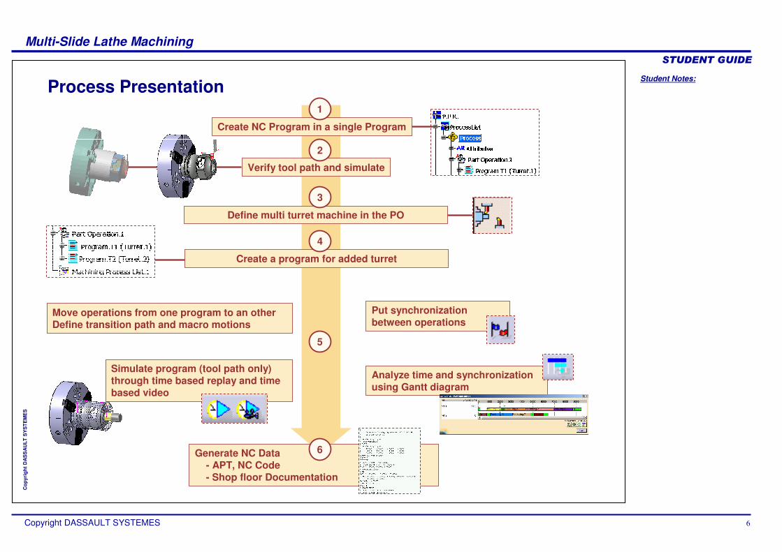
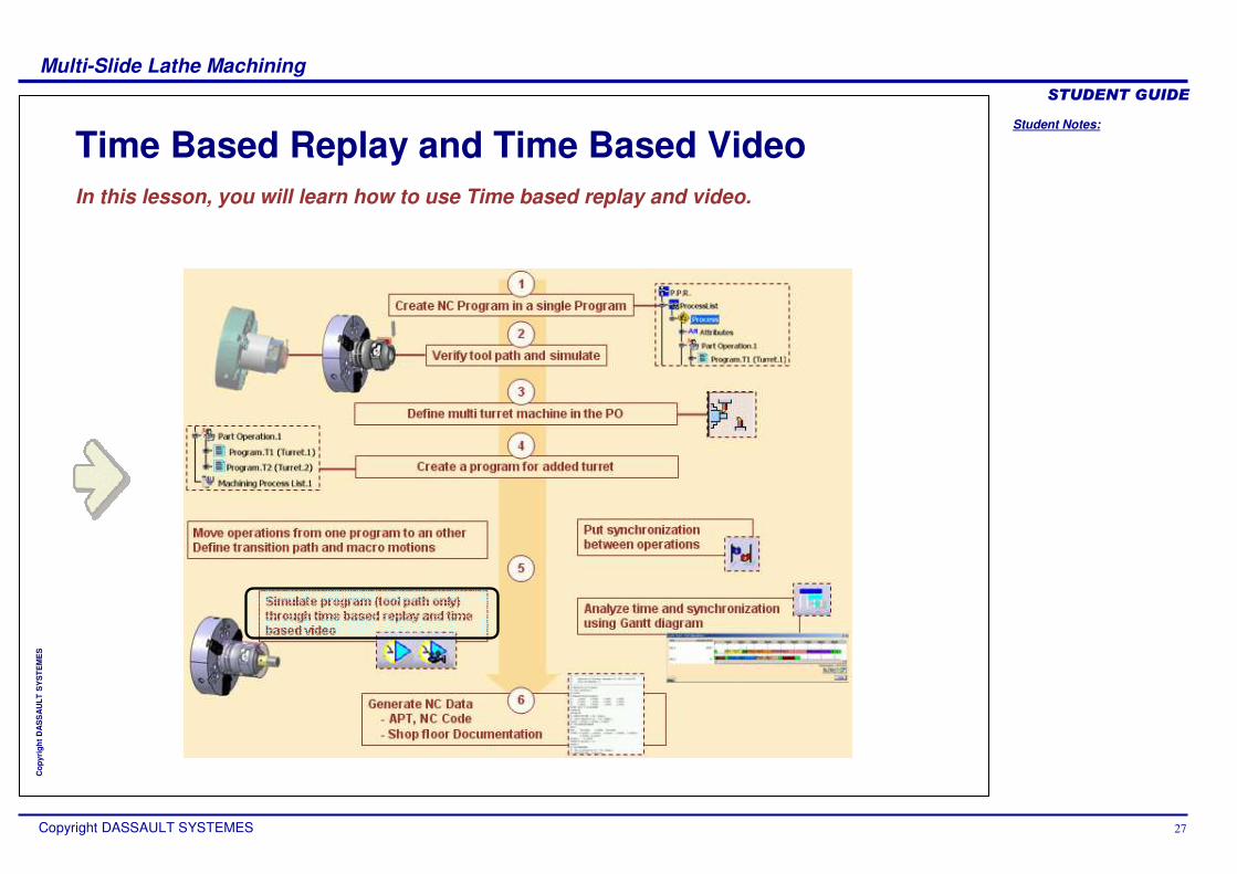
Process Presentation
Simulate program (tool path only) through time based replay and time based video
Analyze time and synchronization using Gantt diagram
Put synchronization between operations
Generate NC Data- APT, NC Code- Shop floor Documentation
Define multi turret machine in the PO
Create NC Program in a single Program
Move operations from one program to an otherDefine transition path and macro motions
Verify tool path and simulate
Create a program for added turret
5
1
6
2
3
4

Student Notes:
Multi-Slide Lathe Machining������������
Copyright DASSAULT SYSTEMES 7
Cop
yrig
ht D
AS
SA
ULT
SY
STE
ME
S
Workbench User Interface
Lathe Machining Workbench:
Auxiliary Commands tool bar:
Synchronisation Management tool bar:

Student Notes:
Multi-Slide Lathe Machining������������
Copyright DASSAULT SYSTEMES 8
Cop
yrig
ht D
AS
SA
ULT
SY
STE
ME
S
Machine DefinitionIn this lesson, you will learn how to define a Multi turret or Multi spindle Machine.

Student Notes:
Multi-Slide Lathe Machining������������
Copyright DASSAULT SYSTEMES 9
Cop
yrig
ht D
AS
SA
ULT
SY
STE
ME
S
1. Edit the Part Operation
2. Access to the Machine definition windows
3. Select Multi-slide Lathe Machine
4. Define usual parameters for Numerical Control, Tooling, Compensation
Definition of the Machine Parameters
PP table sample for Multi-slide lathe Machining
You can assign a kinematic Multi-slide lathe machine to a Part operation. This machine must be a CATProduct representation created using the NC Machine Tool Builder product.

Student Notes:
Multi-Slide Lathe Machining������������
Copyright DASSAULT SYSTEMES 10
Cop
yrig
ht D
AS
SA
ULT
SY
STE
ME
S
Definition of the Spindle (1/2)
Name of the Spindle
Number of the spindle
Define the Part Axis System of the spindle :the Axis System of the main spindle = Part Machining Axis system (define in Part Operation panel) they are automatically linked
Define Spindle axis
Define Radial axis
Define the Max spindle speed:Attribute used in time computation when machining at constant cutting speed go over this value
1. Access to Spindle tab page in Machine editor panel
2. Define the main spindle: Spindle is the first one in the list & you cannot remove it

Student Notes:
Multi-Slide Lathe Machining������������
Copyright DASSAULT SYSTEMES 11
Cop
yrig
ht D
AS
SA
ULT
SY
STE
ME
S
Definition of the Spindle (2/2)
Click on Add Spindle button
Redefine the parameters as for the main spindle:
Name of the SpindleNumber of the spindleDefine the Part Axis System of the spindleDefine Spindle axisDefine the Max spindle speed
3. Define other spindle:
4. To remove a Spindle, click on Remove Spindle button
Student Notes:
Multi-Slide Lathe Machining������������
Copyright DASSAULT SYSTEMES 12
Cop
yrig
ht D
AS
SA
ULT
SY
STE
ME
S
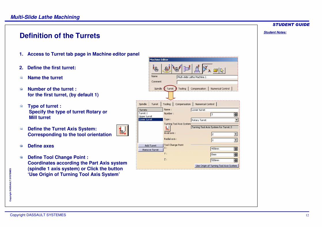
Name the turret
Number of the turret :for the first turret, (by default 1)
Type of turret :Specify the type of turret Rotary orMill turret
Define the Turret Axis System:Corresponding to the tool orientation
Define axes
Define Tool Change Point : Coordinates according the Part Axis system (spindle 1 axis system) or Click the button ‘Use Origin of Turning Tool Axis System’
Definition of the Turrets
1. Access to Turret tab page in Machine editor panel
2. Define the first turret:
Student Notes:
Multi-Slide Lathe Machining������������
Copyright DASSAULT SYSTEMES 13
Cop
yrig
ht D
AS
SA
ULT
SY
STE
ME
S
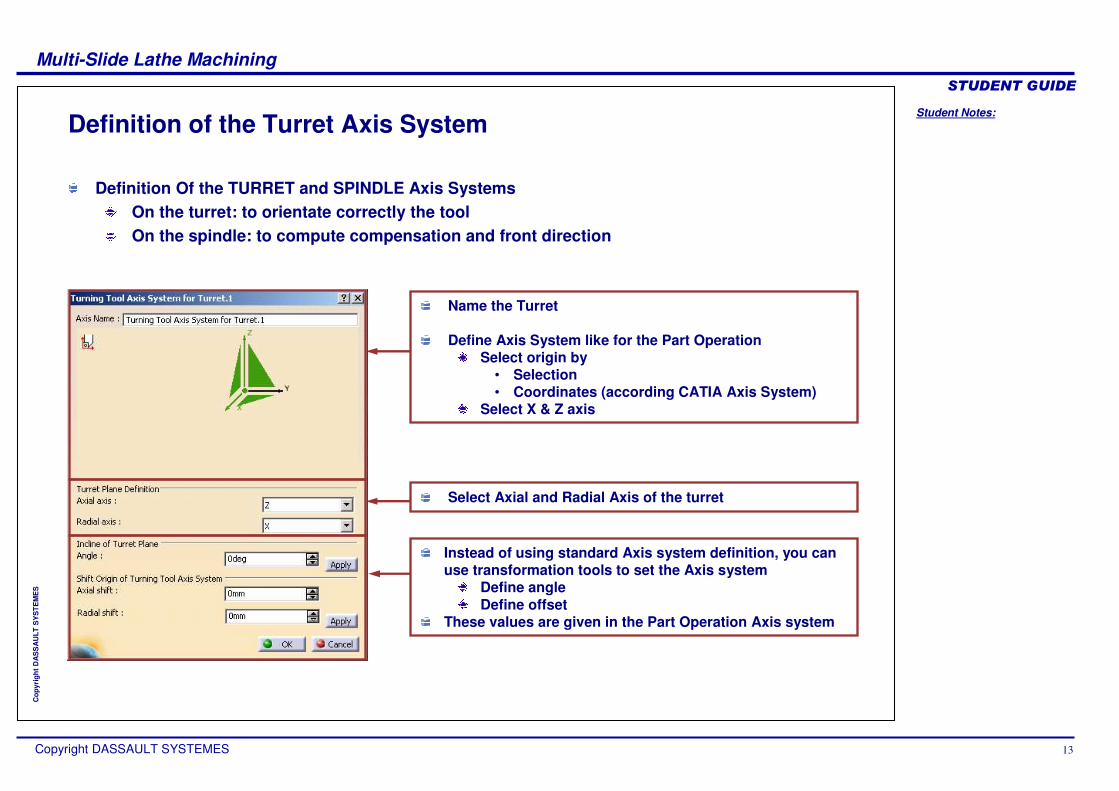
Definition of the Turret Axis System
Name the Turret
Define Axis System like for the Part Operation Select origin by
• Selection• Coordinates (according CATIA Axis System)
Select X & Z axis
Select Axial and Radial Axis of the turret
Instead of using standard Axis system definition, you can use transformation tools to set the Axis system
Define angleDefine offset
These values are given in the Part Operation Axis system
Definition Of the TURRET and SPINDLE Axis SystemsOn the turret: to orientate correctly the tool On the spindle: to compute compensation and front direction

Student Notes:
Multi-Slide Lathe Machining������������
Copyright DASSAULT SYSTEMES 14
Cop
yrig
ht D
AS
SA
ULT
SY
STE
ME
S
To Sum Up
An example after defining the Spindles, Turrets and Axis Systems is as shown below:

Student Notes:
Multi-Slide Lathe Machining������������
Copyright DASSAULT SYSTEMES 15
Cop
yrig
ht D
AS
SA
ULT
SY
STE
ME
S
Create Manufacturing ProgramsIn this lesson, you will see recommendations concerning the way of create NC programs.

Student Notes:
Multi-Slide Lathe Machining������������
Copyright DASSAULT SYSTEMES 16
Cop
yrig
ht D
AS
SA
ULT
SY
STE
ME
S
A Manufacturing Program is associated to a specific TurretIn Part Operation, you should have at least the same number of Manufacturing Program as the number of Turret you have defined
To associate a turret to a Manufacturing Program: Edit the Program (double-click or Contextual menu + Properties)Select the turret in the combo list
How to Create Manufacturing Programs
Edit
Student Notes:
Multi-Slide Lathe Machining������������
Copyright DASSAULT SYSTEMES 17
Cop
yrig
ht D
AS
SA
ULT
SY
STE
ME
S
Turret Station Editor on the Manufacturing Program
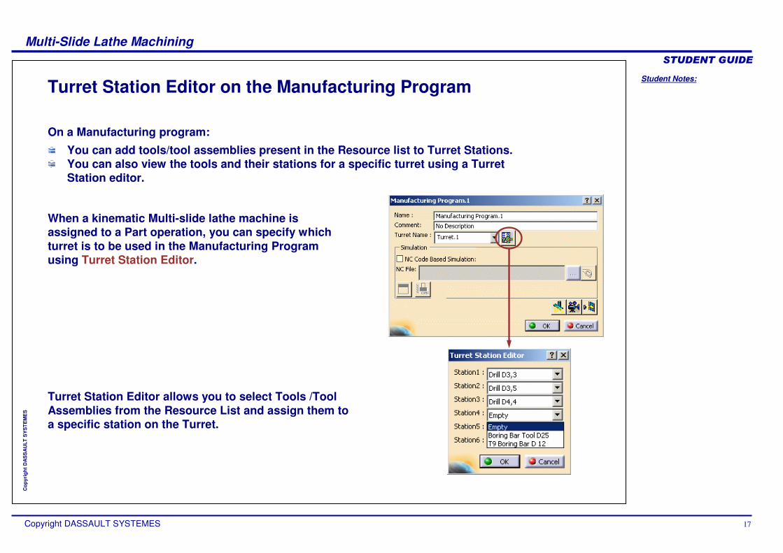
On a Manufacturing program:
You can add tools/tool assemblies present in the Resource list to Turret Stations. You can also view the tools and their stations for a specific turret using a Turret Station editor.
When a kinematic Multi-slide lathe machine is assigned to a Part operation, you can specify which turret is to be used in the Manufacturing Program using Turret Station Editor.
Turret Station Editor allows you to select Tools /Tool Assemblies from the Resource List and assign them to a specific station on the Turret.

Student Notes:
Multi-Slide Lathe Machining������������
Copyright DASSAULT SYSTEMES 18
Cop
yrig
ht D
AS
SA
ULT
SY
STE
ME
S
Create SynchronizationsIn this lesson, you will see recommendations to put Synchronizations between Machining Operations.

Student Notes:
Multi-Slide Lathe Machining������������
Copyright DASSAULT SYSTEMES 19
Cop
yrig
ht D
AS
SA
ULT
SY
STE
ME
S
Create synchronization between two operationsClick ‘Creates a synchronization’ iconSelect an operation of a turretSelect an operation of an other turretSelect where in the operations, you wantto put the synchronization � Start� After Approach macro (Turning operations)
– Approach motion should be define at the operation level
� Before Retract macro (Turning operations) – Retract motion should be define at the
operation level � End
Define which turret drive the other one in a feedrate point of view
How to Create Synchronizations (1/2)
To Optimize machining time, it is necessary to make machining on the different turrets at the same time. To control the starting point or the end point of a machining operation, you must create synchronization between two operations.
The pasted operation which is cut or copied can not synchronized.

Student Notes:
Multi-Slide Lathe Machining������������
Copyright DASSAULT SYSTEMES 20
Cop
yrig
ht D
AS
SA
ULT
SY
STE
ME
S
How to Create Synchronizations (2/2)
Synchronizations are not visible in the ProcessList (PPR tree). They are visible only in the Gantt chart view (see next Lesson for all info concerning Gantt Chart)
In the Gantt Chart view, the Synchronization are visualized by a line with a number and a point in red color
To delete a synchronization : use contextual menu on the line + deleteLine allows to put time correlation between the two machining operations (A)The number is the number of the synchronization (B)The Point indicate which turret is the master (C)
C
A
B

Student Notes:
Multi-Slide Lathe Machining������������
Copyright DASSAULT SYSTEMES 21
Cop
yrig
ht D
AS
SA
ULT
SY
STE
ME
S
Gantt Chart ViewIn this lesson, you will learn how to use Gantt Chart view.
Student Notes:
Multi-Slide Lathe Machining������������
Copyright DASSAULT SYSTEMES 22
Cop
yrig
ht D
AS
SA
ULT
SY
STE
ME
S
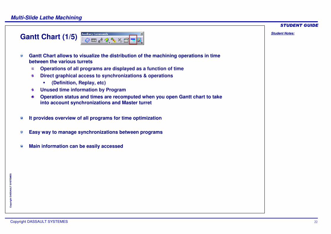
Gantt Chart (1/5)
Gantt Chart allows to visualize the distribution of the machining operations in time between the various turrets
Operations of all programs are displayed as a function of timeDirect graphical access to synchronizations & operations � (Definition, Replay, etc)
Unused time information by ProgramOperation status and times are recomputed when you open Gantt chart to take into account synchronizations and Master turret
It provides overview of all programs for time optimization
Easy way to manage synchronizations between programs
Main information can be easily accessed

Student Notes:
Multi-Slide Lathe Machining������������
Copyright DASSAULT SYSTEMES 23
Cop
yrig
ht D
AS
SA
ULT
SY
STE
ME
S
Gantt Chart (2/5)
Turret namesOperation not computed or operation time = 0s
Time scale (s): Unit can be changed in tool / option / Parameters & measures / Unit menu
Synchronization
Put the cursor on the operation ���� long help infoSelect the operation ���� highlight in the PPR treeDouble click ���� edit the operationContextual menu ���� access to following menu
Time during which the turret is waiting for the others)
Time Based Replay bar
Synchro numbers
Time scale
Student Notes:
Multi-Slide Lathe Machining������������
Copyright DASSAULT SYSTEMES 24
Cop
yrig
ht D
AS
SA
ULT
SY
STE
ME
S
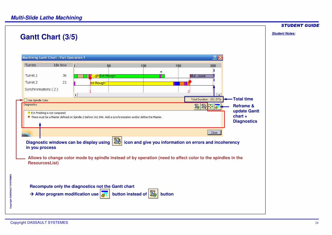
Gantt Chart (3/5)
Diagnostic windows can be display using icon and give you information on errors and incoherency in you process
Reframe & update Gantt chart + Diagnostics
Total time
Allows to change color mode by spindle instead of by operation (need to affect color to the spindles in the ResourcesList)
Recompute only the diagnostics not the Gantt chart
���� After program modification use … button instead of … button

Student Notes:
Multi-Slide Lathe Machining������������
Copyright DASSAULT SYSTEMES 25
Cop
yrig
ht D
AS
SA
ULT
SY
STE
ME
S
Gantt Chart (4/5)
‘Total time’ of operations and ‘Unused time’ are used for computing the Part Operation overall time.
For machining activities, total time is the ‘Calculated cycle time’ automatically set when computing the tool path For non machining activities (Tool Change, PP
Instruction and Machine Rotation), total time is the value entered in ‘Specified cycle time’ that is used.
Time Computation:During synchronization definition, we can set a turret as Master. Then this turret drives spindle speed for time computation of machining operations on all other turrets As long as there is no new synchronization order with a change in the definition of the master, this turret remains master and the operations on it drive the othersIf turrets works together without definition of master, a warning message is displayed in the diagnostic window (NC Gantt Chart) and computation of real time won't go any further

Student Notes:
Multi-Slide Lathe Machining������������
Copyright DASSAULT SYSTEMES 26
Cop
yrig
ht D
AS
SA
ULT
SY
STE
ME
S
Gantt Chart (5/5)
Colors of activities can be set using Graphic Properties tool barFor Process activities (operation PPword, tool change)For Resources activities (spindles)
Student Notes:
Multi-Slide Lathe Machining������������
Copyright DASSAULT SYSTEMES 27
Cop
yrig
ht D
AS
SA
ULT
SY
STE
ME
S
Time Based Replay and Time Based VideoIn this lesson, you will learn how to use Time based replay and video.

Student Notes:
Multi-Slide Lathe Machining������������
Copyright DASSAULT SYSTEMES 28
Cop
yrig
ht D
AS
SA
ULT
SY
STE
ME
S
About Time Based Replay
Time-based Replay simulates all the activities as a function of timefrom the absolute start time of the Part Operationfrom the start time of a selected operation : all simultaneous and following operations are replayed
Time based replay allows checking Program sequence and Synchronization influences. It also allows checking potential collisions between tools.
If referenced tooling is shared by at least one simultaneous operation of another turret, you must duplicate this tooling in order to view all simultaneous tooling positions.

Student Notes:
Multi-Slide Lathe Machining������������
Copyright DASSAULT SYSTEMES 29
Cop
yrig
ht D
AS
SA
ULT
SY
STE
ME
S
Time Based Replay: General Process
Display simulated activities
Select activity to simulateOr select time range
Real time simulation
Lock
1
2
34
1. Select the Part Operation and click Time Based Replay icon2. Define simulation options (optional)3. Use control buttons (Run, …)4. Control collisions & synchronization

Student Notes:
Multi-Slide Lathe Machining������������
Copyright DASSAULT SYSTEMES 30
Cop
yrig
ht D
AS
SA
ULT
SY
STE
ME
S
About Time Based Video
Time based video allows you to simulate multi-turret and multi-spindle scenarios with synchronized operations as defined in the Machining Gantt viewer.
You can set the video simulation time step for customized visualization.
The video functionalities such as save video result as CATProduct, collision lists, video analysis commands are available in time based video simulation.
Time based video is available for multi-turret machines.

Student Notes:
Multi-Slide Lathe Machining������������
Copyright DASSAULT SYSTEMES 31
Cop
yrig
ht D
AS
SA
ULT
SY
STE
ME
S
Time Based Video: General Process
1
3
4
1. Select the Part Operation and click Time Based Video iconThe Process Simulation command box appears with the stock representation.
2. Define simulation options (optional)3. Use control buttons (Run, …)4. Control collisions & synchronization
2
The video result can be saved by using the command Save as CATProduct
You can perform Video analysis using the different analysis commands in the Analysis tool bar such as Analyze, Video Measure , Measure and Remove Chunks.
You can check and save the collisions.

Student Notes:
Multi-Slide Lathe Machining������������
Copyright DASSAULT SYSTEMES 32
Cop
yrig
ht D
AS
SA
ULT
SY
STE
ME
S
NC OutputsIn this lesson, you will learn how to generate NC Code.
Student Notes:
Multi-Slide Lathe Machining������������
Copyright DASSAULT SYSTEMES 33
Cop
yrig
ht D
AS
SA
ULT
SY
STE
ME
S
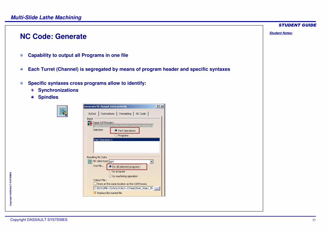
NC Code: Generate
Capability to output all Programs in one file
Each Turret (Channel) is segregated by means of program header and specific syntaxes
Specific syntaxes cross programs allow to identify:SynchronizationsSpindles

Student Notes:
Multi-Slide Lathe Machining������������
Copyright DASSAULT SYSTEMES 34
Cop
yrig
ht D
AS
SA
ULT
SY
STE
ME
S
$$ ----------------------------------------…CHANNEL,1 ...$$ Start : External lathe roughingSYNC/1,1,2,1...$$ End : External lathe roughing...$$ Start : Internal lathe recessingSYNC/2,2,1,1...$$ End : Internal lathe recessing...END
$$ ----------------------------------------…CHANNEL,2...$$ Start : Axial drilling SYNC/1,1,2,1...SYNC/2,2,1,1$$ End : Axial drilling ...END
NC Code: Customize PPTable
1st synchro
2nd synchro
New parameter for channels: MFG_CHANNEL_NUMBERNC Command ‘NC_SYNCHRONISATION’ and related parameters for synchronizations
PP Table specification :
*START_NC_INSTRUCTION NC_START_MACROCHANNEL,%MFG_CHANNEL_NUMBER*END
*START_NC_COMMAND NC_SYNCHRONISATIONSYNC/%MFG_SYNCHRONISATION_NUMBER,%MFG_CHANNEL1,%MFG_CHANNEL2,%MFG_MASTER_CHANNEL*END

Student Notes:
Multi-Slide Lathe Machining������������
Copyright DASSAULT SYSTEMES 35
Cop
yrig
ht D
AS
SA
ULT
SY
STE
ME
S
Create the NC ProgramsIn this lesson, you will review the global process.
Student Notes:
Multi-Slide Lathe Machining������������
Copyright DASSAULT SYSTEMES 36
Cop
yrig
ht D
AS
SA
ULT
SY
STE
ME
S
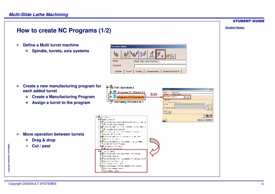
How to create NC Programs (1/2)
Move operation between turretsDrag & dropCut / past
Define a Multi turret machineSpindle, turrets, axis systems
Create a new manufacturing program for each added turret
Create a Manufacturing ProgramAssign a turret to the program
Edit
Student Notes:
Multi-Slide Lathe Machining������������
Copyright DASSAULT SYSTEMES 37
Cop
yrig
ht D
AS
SA
ULT
SY
STE
ME
S
How to create NC Programs (2/2)
For multi SpindlesAffect the spindle at the Machining Operation levelIn the NC assembly, add the second spindle with the part like in reality
Add macro motions
Put synchronization between operationsSelect where in the operations, you want to put the synchronization Define which turret drive the other one
Check coherency with Gantt diagram
Control / simulate to check collision (only visual detection)

Student Notes:
Multi-Slide Lathe Machining������������
Copyright DASSAULT SYSTEMES 38
Cop
yrig
ht D
AS
SA
ULT
SY
STE
ME
S
Multi Spindle, Multi Turret Assembly
Main spindle
Counter spindle

Student Notes:
Multi-Slide Lathe Machining������������
Copyright DASSAULT SYSTEMES 39
Cop
yrig
ht D
AS
SA
ULT
SY
STE
ME
S
Counter Spindle Output
You can compute the tool tip points for turning operations that are defined on the counter spindle with respect to counter spindle part axis system rather than the main spindle part axis system.
You need to select ‘Use Spindle Axis System according to the Spindle involved on the Machining Operation’checkbox in the Option tab of the Part Operation. When you select this checkbox the tool tip points will be computed based on the spindle and its axis system that you have set.If the checkbox is not checked then the main spindle axis is taken into account.
You can set a counter spindle for a particular machining operation through Spindle name in Strategy tab. For this, you need to assign multiple spindles in machine editor.
Machine Axis change is not required even if multi-spindle are used.
Related Documents