MULTI-SCIENCE PUBLISHING CO. LTD. 5 Wates Way, Brentwood, Essex CM15 9TB, United Kingdom Reprinted from INTERNATIONAL JOURNAL OF SPACE STRUCTURES Volume 25 · Number 3 · 2010 Parametric studies on the behaviour of steel and composite space structures by K.N. Lakshmikandhan, R. Senthil, S. Arul Jayachandran,P. Sivakumar, R. Ravichandran

Welcome message from author
This document is posted to help you gain knowledge. Please leave a comment to let me know what you think about it! Share it to your friends and learn new things together.
Transcript
M U LT I - S C I E N C E P U B L I S H I N G C O . LT D .
5 Wates Way, Brentwood, Essex CM15 9TB, United Kingdom
Reprinted from
INTERNATIONAL JOURNAL OF
SPACE STRUCTURESVolume 25 · Number 3 · 2010
Parametric studies on the behaviourof steel and composite space structures
by
K.N. Lakshmikandhan, R. Senthil, S. Arul Jayachandran,P. Sivakumar, R. Ravichandran
INTRODUCTIONSkeletal steel space frames are used to cover largecolumn free areas, due to their aesthetic appearance,light weight, easy fabrication, reassembling andhigher percentage of reusability. These spacestructures have high rigidity and stiffness for a givenspan to depth ratio. They have the ability toredistribute large concentrated or unsymmetricalloading. Their higher integrity and stability to loadsalso offer a possibility of their use in the constructionof bridges. In spite of numerous advantages, thecompressive members of steel space structures maybuckle, leading to catastrophic failures. A number ofresearchers carried out numerical, analytical andexperimental studies to improve the performance ofcompression chord members and the overall trussbehavior. One such option is to have a concrete slabon the top of the space grid, which effectivelyimproves the compression capacity of top chordmembers.
Parametric Studies onthe Behavior of Steel and
Composite Space StructuresLakshmikandhan K N1, Senthil R2, Arul Jayachandran S3, Sivakumar P1
and Ravichandran R1
1Scientist, CSIR, SERC, Taramani, Chennai, India -6001132Assistant Professor, Structural Engineering Division, Anna University, Chennai, India -600025.
E-mail:[email protected] Professor, IIT Madras, Chennai, India -600036.
Submitted 05/October/2009 – Revised version 18/May/2010 – Acceptation 28/ May/2010
ABSTRACT: Double layered grid space structures are well known in thebuilding industry for their ability to cover large areas. This paper presents theresults of a parametric study on the various factors affecting the flexuralbehavior of double layered grid space structures, considering (i) varioussupport arrangement (ii) concrete slab at the top and (iii) an experimentalinvestigation on a full scale space grid. Based on the study it was concludedthat top concrete slab enhances not only the strength of top chord compressionmembers but also increase the strength and stiffness of the system with a failsafe system. It was found from the study that atleast 20% saving in steel ispossible with a mid edge supported system.
Keywords: space structures, double layer grids, steel concrete composite,limit state design, steel tubes
International Journal of Space Structures Vol. 25 No. 3 2010 169
This paper mainly deals with the effectiveness ofconcrete slab in the composite space truss system andthe effects of support arrangements in both the steelspace structure (here after designated as non-composite space structure) and steel space truss withconcrete slab (designated as composite spacestructure).
REVIEW OF LITERATURESmith (1984) presented detailed information about thedevelopment of a numerical method and listed thealgorithm considering the chordal snap through. Hebriefly described the single step linearization,piecewise linearization and stepwise linearizationmethods. A nonlinear stepwise linearization analysismethod is based on the number of single steplinearization and can model the behavior as accuratelyas the piecewise linearization. This does not requirethe repeated updating of the structural stiffness matrixwhich reduces the computation cost. See andMcConnel (1986) used a nonlinear stiffness approach
for the elastic stability analysis of space framestructures; the likely failure modes of the structurewere determined from the tangent stiffness matrix nearthe collapse load. Madi (1987) analytically examinedthe steel space truss behavior with the differentsupport positions, grid depths, grid modules andlayouts. The square type grids were performing wellcompared with the rectangular grids. Smith (1988)examined the vulnerability of space trusses toprogressive collapse. The structure was analyzed withthe alternate path method, in which one member isremoved, and the effect was studied. There were somesimilarities in the unsafe members of the linearanalysis and the buckling members in the nonlinearanalysis. It was concluded that to control progressivecollapse, compression members and diagonals alongand adjacent to the column line should be overdesigned, particularly in the middle half of the span.Ariel Hanaor et al (1989) critically reviewed andsuggested for a conservative approach to compressionmember or reduce the allowable stresses incompression members of the order of 15-25%compared to conventional column design. They alsoreviewed the possible modes of enhancing thebehaviour of compression members like under-overdesign of chords, eccentric diagonals, diagonalremoval, prestress by lack of fit and by the use of forcelimiting devices.
Smith and Paul Magyar (1991) studied the behaviorof eccentrically loaded, cold-formed steel, lipped-channel compression members of a space framesystem. The peak loads are found by the secantformula for negative eccentricities between the shearcenter and close to the centroid. For small negativeeccentricities close to the centroid and for positiveeccentricities, the torsional-flexural buckling loadcontrols. However, because of restraint of warpingmechanisms at the supports, the capacity was greater.Akira Wada et al. (1992) investigated the mechanicalbehavior of space truss for the uncertainties and itsinfluence. The variations of member length due toinitial imperfection and the error in assembly processwere chosen. The author also summarized thestructural outlines, description of collapse and cause ofcollapse from January 1987 to October 1989.
El-Sheikh et al. (1993) investigated the ways toovercome the brittle type of failures caused by thebuckling of compressive chord members andsuccessive buckling of a series of critical compression-chord members by introducing over strengthened topchord members and by introducing slab over the top
chord member. Smith (1994) reviewed thecomputational models used for compression membersin the nonlinear analysis of space trusses. The finite-segment and finite-difference methods were used inmodeling experimental behavior of pin-endedmembers. The assumption that the shape of themember approximates a sine curve throughout themember history gave reasonably accurate results and itis observed that consideration also needed to be givento the relationship between the member and thestructure to which the member is attached. Thus,internal snap-through or dynamic jump can occur inthe post buckling regime of compression members in arelatively compliant adjacent structure. Malla andNalluri (1995) studied and reported the effect ofdynamic member failure on the truss structure.
Blandford (1996) developed a nonlinear space trussanalysis program using linearized nonlinear updatedLagrangian equation to carry out the static analysis ofspace structures including the material inelastic andgeometrical nonlinearities. The premature progressivecollapse due to the interaction of the differentnonlinear behaviors modes including buckling,yielding, inelastic post buckling, unloading andreloading was reported. El-Sheikh (1996) presented anoverall view on the work carried out recently on theeffect of composite action on space truss. Fourdifferent techniques are discussed to developcomposite action efficiently. In all the four methodsthe use of corrugated decking sheets and welded shearstuds were used. Malla and Serrette (1996a) reviewedthe static and thermal analysis including linear,nonlinear and stability analysis of double layer grids.The instability of a single member can result in aprogressive collapse of the structure through loadredistribution and successive buckling or yielding.Malla and Serrette (1996b) presented the state of artreview on the dynamic analysis techniques includedynamic linear, nonlinear and stability analyses,dynamic loadings, progressive collapse, dynamiceffects of member failure, optimization techniques,probabilistic methods, vibration control, systemidentification and damage detection, specialapplication DLGs, and methods to modify the spacetruss behaviour. El-Sheikh (1997) tried to improve thebuckling compression member behavior with lack offit in different top, middle, bottom and diagonalmembers and eccentric joints in an attempt to identifythe most critical areas in which no imperfect membersshould be used. El-Sheikh (1998, 1999, 2000 and2000b) considered the continuous top and bottom
170 International Journal of Space Structures Vol. 25 No. 3 2010
Parametric Studies on the Behavior of Steel and Composite Space Structures
Lakshmikandhan K N, Senthil R, Arul Jayachandran S, Sivakumar P and Ravichandran R
chord members and eccentric joints. The analysesconsidered both geometric nonlinearities due to jointbuckling, yielding and change of joint coordinates andmaterial nonlinearities due to yielding, cracking andcrushing. The member imperfections had almost noeffect on truss performance for the composite truss.
El-Sheikh (1999) also presented the designmethodology for the composite space truss. El-Sheikh(1999b) used the force limiting devices to alter thebrittle post-buckling characteristics of trusscompression members. Tin-Loi et al. (1999) presentedgeneral frame work for the nonlinear geometricanalysis of the elastic truss. The total lagrangian andfinite incremental formulation are developed using thestatic, kinematics and constitutive law as the three keyfactors. A simple arc length based procedure has beenadopted as a solver. Akio Hori et al. (2000) presentedthe analytical results of the partial models and shownthat coupled buckling between several continuouschords appears to be asymmetric because of thedifference in axial forces allowed by adjacentmembers. It is possible to analyze a large andcomplicated space frame with elastoplastic coupledbuckling up to a large deformed state. Malla et al(2000) presented the computational procedure forarrive the response of truss structures subjected tomember failure under static and dynamic loading.Bradshaw et al. (2002) discussed various developmentstages of long span structures, recent scenario andfuture directions. Fulop et al. (2004) conductedexperiments on space truss with concentric andeccentric loads. The collapse of truss was due to thelocal buckling of two opposite diagonals at the topcentre joint. Lakshmikandhan et al. (2005 and 2009)presented the effect of different angle of inclination ofdiagonal members of different spans. In this study, theauthors examined the behavior of trusses with aconstant depth and constant grid size. They reportedthat the trusses perform well when the angle ofinclination of diagonal members is between 40 and 60degree and they suggested 45 degree and 60mmconcrete slab thickness to be more beneficial.
From the literature review, it is seen that severalalternate methods have been adopted to overcome thesudden progressive failure due to compressionmember buckling. Methods such as preventing theoverloading, improving the behavior of sections,introducing heavier sections, and introducingmechanical devices have been suggested. The abovesolutions may be uncertain and unreliable for practicalapplications. The problems in the above techniques, to
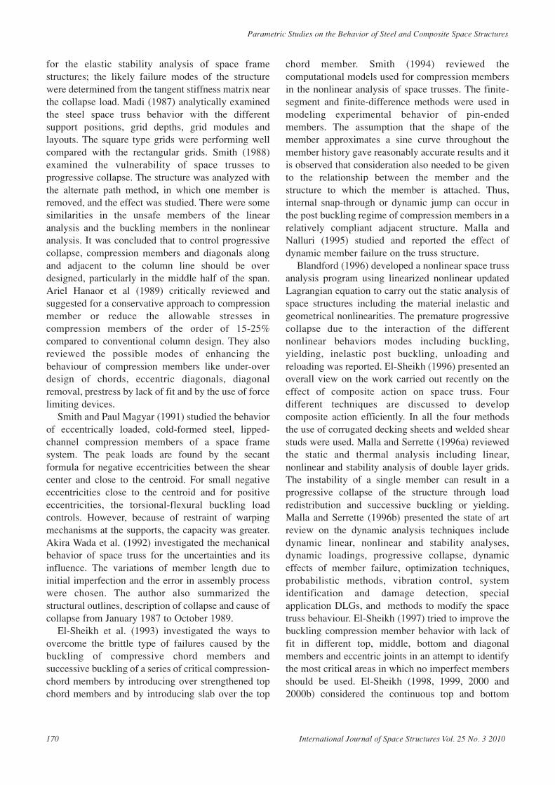
a great extent, may be overcome in steel concretecomposite construction, in which the strengths of bothmaterials are effectively utilized. In composite spacestructures, steel sections are used as bottom chordtension members. Concrete slab is used instead of topchord members, where the members are subjected toheavy compression. The concrete slab and steelmembers are connected together with a steel nodeconnector in a three dimensional array. Numerousstudies were conducted on such systems and areavailable in literature for the effective and economictransfer of loads. The MERO® node connector is themost popular among the available commercial nodes.In the present study, the MERO node is used toconnect the bottom chord members and the inclinedmembers. The node at the top grid layer is modified toaccommodate the concrete slab. A steel square plate of100 mm size with 8 mm thickness is welded over thetop of the node. M20 bolts are fixed, which are actingas a shear connector to connect the node and theconcrete. The modified node with shear connectors,the top chord members and the inclined members areshown in Fig.1.
Figure 1. Components of MERO node connector modified attop chord with truss members
Based on the review of literature, the angle ofinclination has been chosen as 45 degree and theparametric study on the square on square offset doublelayer flat grid space truss structure was carried out.The number of supports, support arrangement, steelspace structure with/without concrete slab, resultantweight of steel, the maximum deflection and stiffnessof the structure are the various parameters consideredin the present study. The finite element design packageSTADD Pro was used for the preliminary designoptimization analysis to obtain the suitable pipe
International Journal of Space Structures Vol. 25 No. 3 2010 171
section. The space truss is modeled in ANSYS with thesectional properties obtained from the preliminaryanalysis. From the finite element analysis, themaximum deflection and the maximum stress inconcrete are obtained from the ANSYS post processor.
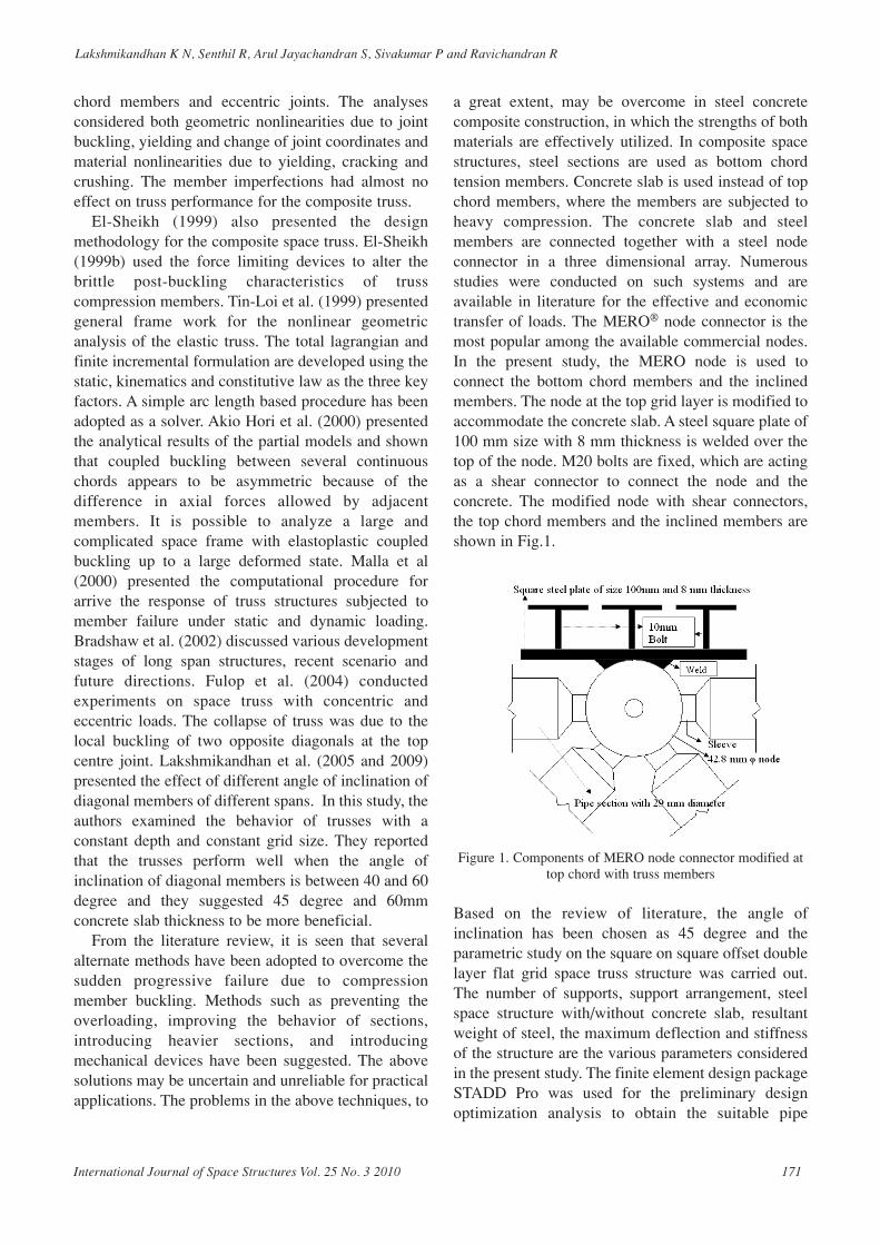
FINITE ELEMENT ANALYSISThe Finite analysis is carried on “square on square”offset double layer flat grid truss. The finite elementdesign package Stadd Pro is used for preliminarydesign optimization analysis to obtain the optimumsize of the truss members. The analysis and designwere carried out with a standard finite element designpackage “STADD Pro”. A typical isometric view ofsquare on square double layer grids model from StaddPro is shown in Fig.2. The truss members are modeledwith two noded beam elements with six degrees offreedom and the concrete slab is modeled with fournoded plate elements with six degrees of freedom pernode. The hinged supports considered for supportingthe space structure.
lx = span in X direction, lZ =span in Z directionFigure 2. Typical square on square double layer space truss
system
The design optimization is carried in Staad Pro toobtain the optimum size of the truss members. Theoptimization is started with the minimum member sizefrom the “user defined” steel table. The “user defined”table is created to utilize the wide range of sectionalproperties by combining the Indian steel circular tubesection (IS 1161) and the British steel circular tubesection (BS 6323: 1982). The material properties fromthe Indian pipe section are used for the pipe design andthe static linear analysis is used for the optimization.The optimization is performed by several iterationsand the iteration is stopped when the consecutiveidentical sections were arrived in the successiveanalysis. From the above method, the individualmembers are assigned with pipe sections
corresponding to their member forces. The practicalapplication needs the grouping of members and thegrouping of members is carried out with a maximumof six number of member sizes for the whole structure.Also it is restricted in the grouping that the top, bottomand the inclined member layers are grouped with 2 to3 member sizes. The analysis in the Stadd Pro iscarried out to obtain the optimum member size,optimum truss weight, the maximum membercompression and the maximum member tension. Thesteel sections are designed according to the Indiancode of practice for steel structures, IS 800:2007.
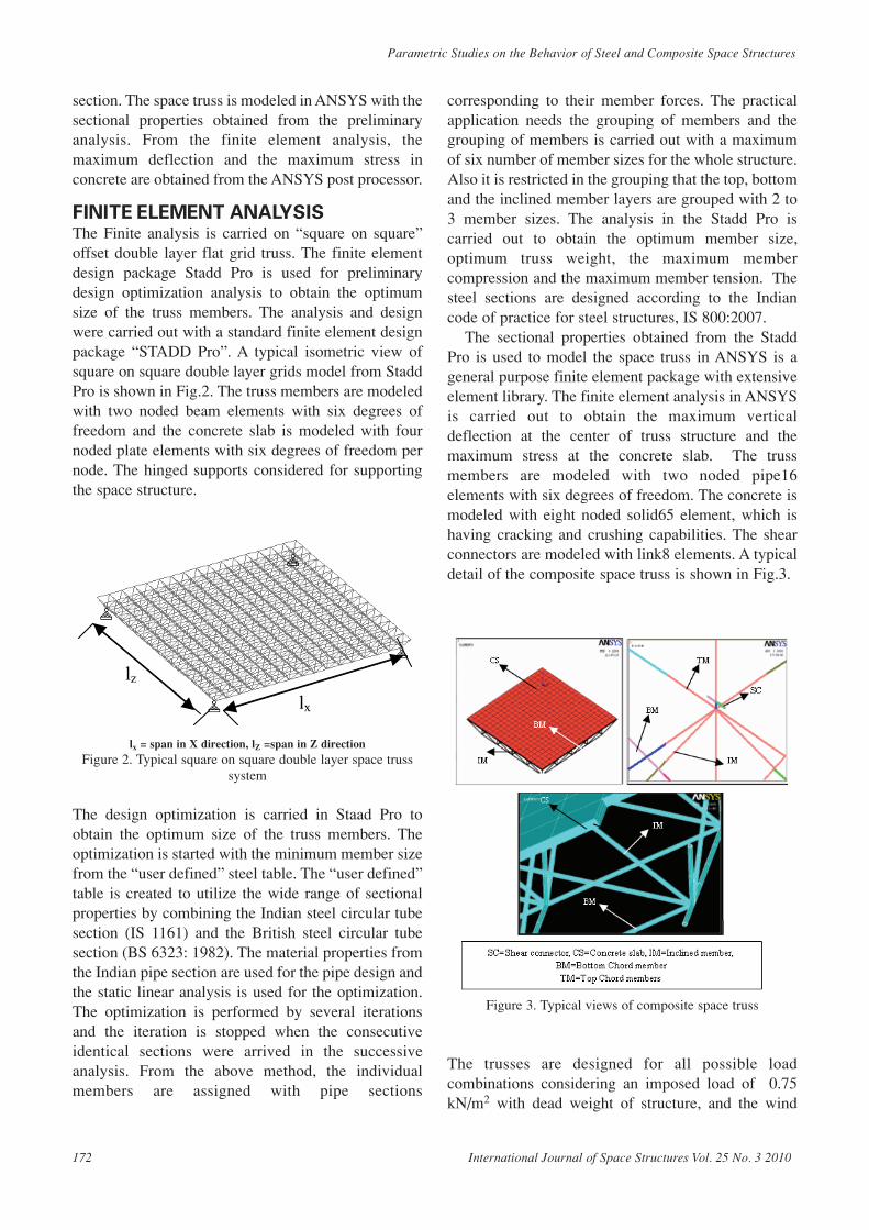
The sectional properties obtained from the StaddPro is used to model the space truss in ANSYS is ageneral purpose finite element package with extensiveelement library. The finite element analysis in ANSYSis carried out to obtain the maximum verticaldeflection at the center of truss structure and themaximum stress at the concrete slab. The trussmembers are modeled with two noded pipe16elements with six degrees of freedom. The concrete ismodeled with eight noded solid65 element, which ishaving cracking and crushing capabilities. The shearconnectors are modeled with link8 elements. A typicaldetail of the composite space truss is shown in Fig.3.
Figure 3. Typical views of composite space truss
The trusses are designed for all possible loadcombinations considering an imposed load of 0.75kN/m2 with dead weight of structure, and the wind
lx
lz
172 International Journal of Space Structures Vol. 25 No. 3 2010
Parametric Studies on the Behavior of Steel and Composite Space Structures
Lakshmikandhan K N, Senthil R, Arul Jayachandran S, Sivakumar P and Ravichandran R
load for madras city with probability factor is 1, terraincategory 3 and the topography factor is 1 is consideredas per IS 875 - Part 3 (Indian code for calculation ofwind loads).
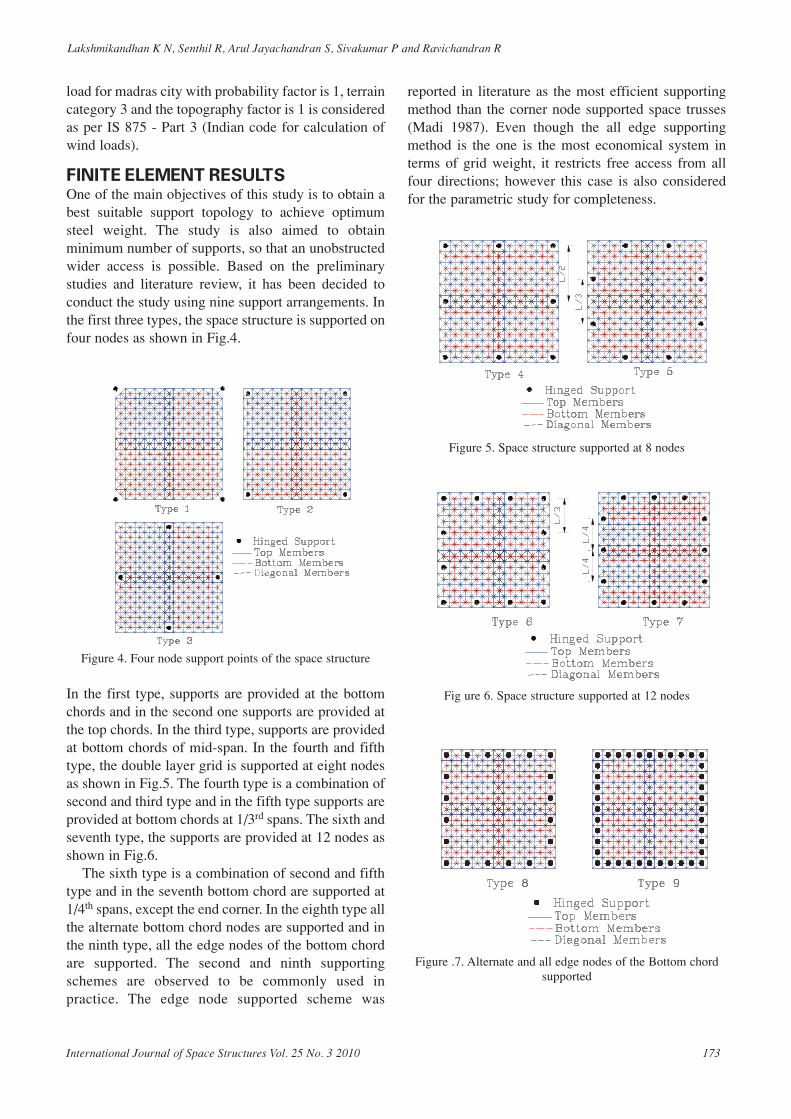
FINITE ELEMENT RESULTS One of the main objectives of this study is to obtain abest suitable support topology to achieve optimumsteel weight. The study is also aimed to obtainminimum number of supports, so that an unobstructedwider access is possible. Based on the preliminarystudies and literature review, it has been decided toconduct the study using nine support arrangements. Inthe first three types, the space structure is supported onfour nodes as shown in Fig.4.
Figure 4. Four node support points of the space structure
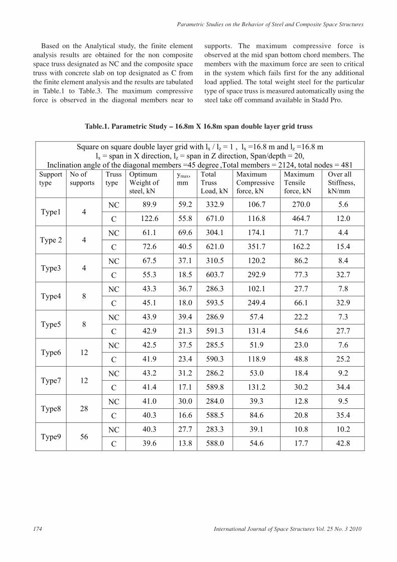
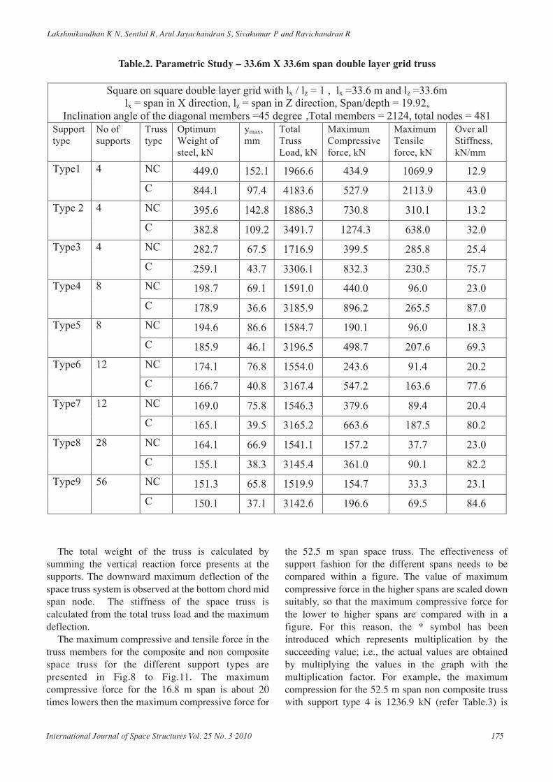
In the first type, supports are provided at the bottomchords and in the second one supports are provided atthe top chords. In the third type, supports are providedat bottom chords of mid-span. In the fourth and fifthtype, the double layer grid is supported at eight nodesas shown in Fig.5. The fourth type is a combination ofsecond and third type and in the fifth type supports areprovided at bottom chords at 1/3rd spans. The sixth andseventh type, the supports are provided at 12 nodes asshown in Fig.6.
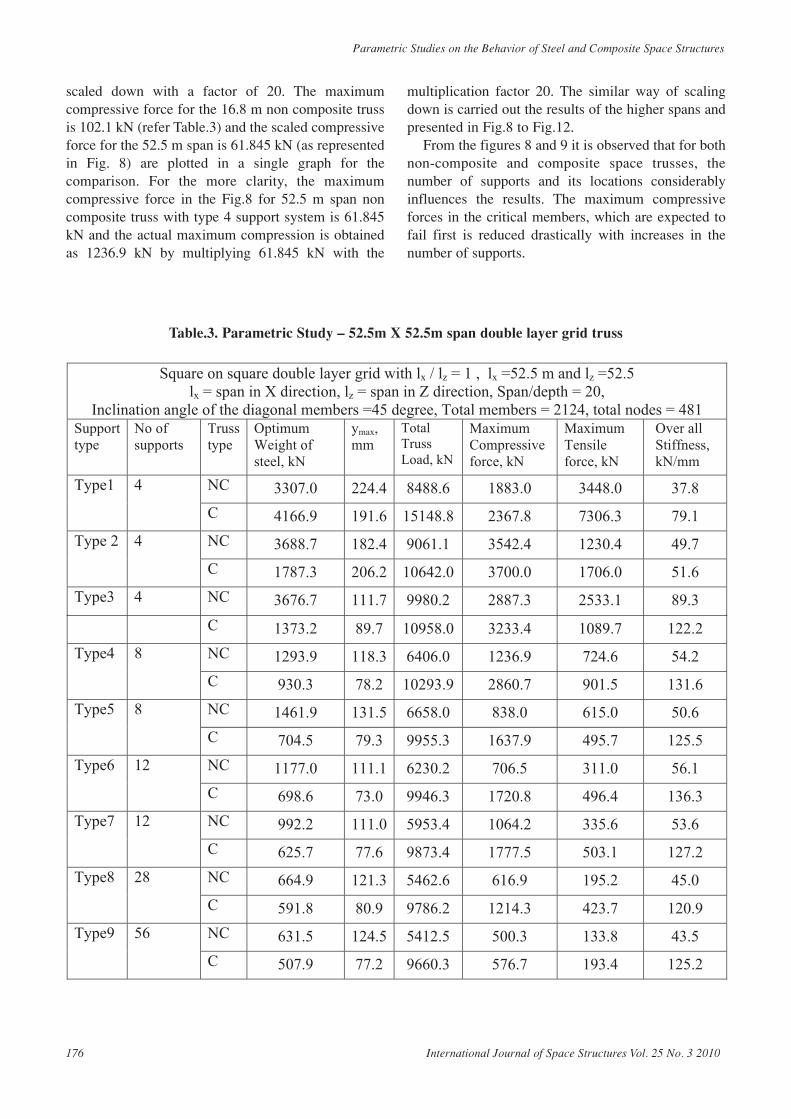
The sixth type is a combination of second and fifthtype and in the seventh bottom chord are supported at1/4th spans, except the end corner. In the eighth type allthe alternate bottom chord nodes are supported and inthe ninth type, all the edge nodes of the bottom chordare supported. The second and ninth supportingschemes are observed to be commonly used inpractice. The edge node supported scheme was
reported in literature as the most efficient supportingmethod than the corner node supported space trusses(Madi 1987). Even though the all edge supportingmethod is the one is the most economical system interms of grid weight, it restricts free access from allfour directions; however this case is also consideredfor the parametric study for completeness.
Figure 5. Space structure supported at 8 nodes
Fig ure 6. Space structure supported at 12 nodes
Figure .7. Alternate and all edge nodes of the Bottom chordsupported
International Journal of Space Structures Vol. 25 No. 3 2010 173
Based on the Analytical study, the finite elementanalysis results are obtained for the non compositespace truss designated as NC and the composite spacetruss with concrete slab on top designated as C fromthe finite element analysis and the results are tabulatedin Table.1 to Table.3. The maximum compressiveforce is observed in the diagonal members near to
supports. The maximum compressive force isobserved at the mid span bottom chord members. Themembers with the maximum force are seen to criticalin the system which fails first for the any additionalload applied. The total weight steel for the particulartype of space truss is measured automatically using thesteel take off command available in Stadd Pro.
174 International Journal of Space Structures Vol. 25 No. 3 2010
Parametric Studies on the Behavior of Steel and Composite Space Structures
Table.1. Parametric Study – 16.8m X 16.8m span double layer grid truss
Square on square double layer grid with lx / lz = 1 , lx =16.8 m and lz =16.8 m
lx = span in X direction, lz = span in Z direction, Span/depth = 20, Inclination angle of the diagonal members =45 degree ,Total members = 2124, total nodes = 481
Support type
No of supports
Truss type
Optimum Weight of steel, kN
ymax, mm
Total Truss Load, kN
Maximum Compressive force, kN
Maximum Tensile force, kN
Over all Stiffness, kN/mm
NC 89.9 59.2 332.9 106.7 270.0 5.6 Type1 4
C 122.6 55.8 671.0 116.8 464.7 12.0
NC 61.1 69.6 304.1 174.1 71.7 4.4 Type 2 4
C 72.6 40.5 621.0 351.7 162.2 15.4
NC 67.5 37.1 310.5 120.2 86.2 8.4 Type3 4
C 55.3 18.5 603.7 292.9 77.3 32.7
NC 43.3 36.7 286.3 102.1 27.7 7.8 Type4 8
C 45.1 18.0 593.5 249.4 66.1 32.9
NC 43.9 39.4 286.9 57.4 22.2 7.3 Type5 8
C 42.9 21.3 591.3 131.4 54.6 27.7
NC 42.5 37.5 285.5 51.9 23.0 7.6 Type6 12
C 41.9 23.4 590.3 118.9 48.8 25.2
NC 43.2 31.2 286.2 53.0 18.4 9.2 Type7 12
C 41.4 17.1 589.8 131.2 30.2 34.4
NC 41.0 30.0 284.0 39.3 12.8 9.5 Type8 28
C 40.3 16.6 588.5 84.6 20.8 35.4
NC 40.3 27.7 283.3 39.1 10.8 10.2 Type9 56
C 39.6 13.8 588.0 54.6 17.7 42.8
Lakshmikandhan K N, Senthil R, Arul Jayachandran S, Sivakumar P and Ravichandran R
The total weight of the truss is calculated bysumming the vertical reaction force presents at thesupports. The downward maximum deflection of thespace truss system is observed at the bottom chord midspan node. The stiffness of the space truss iscalculated from the total truss load and the maximumdeflection.
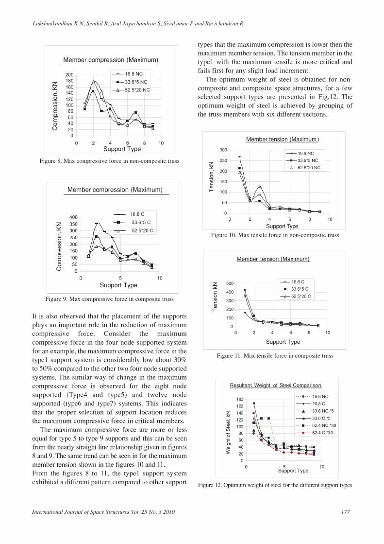
The maximum compressive and tensile force in thetruss members for the composite and non compositespace truss for the different support types arepresented in Fig.8 to Fig.11. The maximumcompressive force for the 16.8 m span is about 20times lowers then the maximum compressive force for
the 52.5 m span space truss. The effectiveness ofsupport fashion for the different spans needs to becompared within a figure. The value of maximumcompressive force in the higher spans are scaled downsuitably, so that the maximum compressive force forthe lower to higher spans are compared with in afigure. For this reason, the * symbol has beenintroduced which represents multiplication by thesucceeding value; i.e., the actual values are obtainedby multiplying the values in the graph with themultiplication factor. For example, the maximumcompression for the 52.5 m span non composite trusswith support type 4 is 1236.9 kN (refer Table.3) is
International Journal of Space Structures Vol. 25 No. 3 2010 175
Table.2. Parametric Study – 33.6m X 33.6m span double layer grid truss
Support type
No of supports
Truss type
Optimum Weight of steel, kN
ymax, mm
Total Truss Load, kN
Maximum Compressive force, kN
Maximum Tensile force, kN
Over all Stiffness, kN/mm
NC 449.0 152.1 1966.6 434.9 1069.9 12.9 Type1 4
C 844.1 97.4 4183.6 527.9 2113.9 43.0
NC 395.6 142.8 1886.3 730.8 310.1 13.2 Type 2 4
C 382.8 109.2 3491.7 1274.3 638.0 32.0
NC 282.7 67.5 1716.9 399.5 285.8 25.4 Type3 4
C 259.1 43.7 3306.1 832.3 230.5 75.7
NC 198.7 69.1 1591.0 440.0 96.0 23.0 Type4 8
C 178.9 36.6 3185.9 896.2 265.5 87.0
NC 194.6 86.6 1584.7 190.1 96.0 18.3 Type5 8
C 185.9 46.1 3196.5 498.7 207.6 69.3
NC 174.1 76.8 1554.0 243.6 91.4 20.2 Type6 12
C 166.7 40.8 3167.4 547.2 163.6 77.6
NC 169.0 75.8 1546.3 379.6 89.4 20.4 Type7 12
C 165.1 39.5 3165.2 663.6 187.5 80.2
NC 164.1 66.9 1541.1 157.2 37.7 23.0 Type8 28
C 155.1 38.3 3145.4 361.0 90.1 82.2
NC 151.3 65.8 1519.9 154.7 33.3 23.1 Type9 56
C 150.1 37.1 3142.6 196.6 69.5 84.6
Square on square double layer grid with lx / lz = 1 , lx =33.6 m and lz =33.6m lx = span in X direction, lz = span in Z direction, Span/depth = 19.92,
Inclination angle of the diagonal members =45 degree ,Total members = 2124, total nodes = 481
scaled down with a factor of 20. The maximumcompressive force for the 16.8 m non composite trussis 102.1 kN (refer Table.3) and the scaled compressiveforce for the 52.5 m span is 61.845 kN (as representedin Fig. 8) are plotted in a single graph for thecomparison. For the more clarity, the maximumcompressive force in the Fig.8 for 52.5 m span noncomposite truss with type 4 support system is 61.845kN and the actual maximum compression is obtainedas 1236.9 kN by multiplying 61.845 kN with the
multiplication factor 20. The similar way of scalingdown is carried out the results of the higher spans andpresented in Fig.8 to Fig.12.
From the figures 8 and 9 it is observed that for bothnon-composite and composite space trusses, thenumber of supports and its locations considerablyinfluences the results. The maximum compressiveforces in the critical members, which are expected tofail first is reduced drastically with increases in thenumber of supports.
176 International Journal of Space Structures Vol. 25 No. 3 2010
Parametric Studies on the Behavior of Steel and Composite Space Structures
Table.3. Parametric Study – 52.5m X 52.5m span double layer grid truss
C 1373.2 89.7 10958.0 3233.4 1089.7 122.2
NC 1293.9 118.3 6406.0 1236.9 724.6 54.2 Type4 8
C 930.3 78.2 10293.9 2860.7 901.5 131.6
NC 1461.9 131.5 6658.0 838.0 615.0 50.6 Type5 8
C 704.5 79.3 9955.3 1637.9 495.7 125.5
NC 1177.0 111.1 6230.2 706.5 311.0 56.1 Type6 12
C 698.6 73.0 9946.3 1720.8 496.4 136.3
NC 992.2 111.0 5953.4 1064.2 335.6 53.6 Type7 12
C 625.7 77.6 9873.4 1777.5 503.1 127.2
NC 664.9 121.3 5462.6 616.9 195.2 45.0 Type8 28
C 591.8 80.9 9786.2 1214.3 423.7 120.9
NC 631.5 124.5 5412.5 500.3 133.8 43.5 Type9 56
C 507.9 77.2 9660.3 576.7 193.4 125.2
Square on square double layer grid with lx / lz = 1 , lx =52.5 m and lz =52.5
lx = span in X direction, lz = span in Z direction, Span/depth = 20, Inclination angle of the diagonal members =45 degree, Total members = 2124, total nodes = 481
Support type
No of supports
Truss type
Optimum Weight of steel, kN
ymax, mm
Total Truss Load, kN
Maximum Compressive force, kN
Maximum Tensile force, kN
Over all Stiffness, kN/mm
NC 3307.0 224.4 8488.6 1883.0 3448.0 37.8 Type1 4
C 4166.9 191.6 15148.8 2367.8 7306.3 79.1
NC 3688.7 182.4 9061.1 3542.4 1230.4 49.7 Type 2 4
C 1787.3 206.2 10642.0 3700.0 1706.0 51.6
Type3 4 NC 3676.7 111.7 9980.2 2887.3 2533.1 89.3
Lakshmikandhan K N, Senthil R, Arul Jayachandran S, Sivakumar P and Ravichandran R
Figure 8. Max compressive force in non-composite truss
Figure 9. Max compressive force in composite truss
It is also observed that the placement of the supportsplays an important role in the reduction of maximumcompressive force. Consider the maximumcompressive force in the four node supported systemfor an example, the maximum compressive force in thetype1 support system is considerably low about 30%to 50% compared to the other two four node supportedsystems. The similar way of change in the maximumcompressive force is observed for the eight nodesupported (Type4 and type5) and twelve nodesupported (type6 and type7) systems. This indicatesthat the proper selection of support location reducesthe maximum compressive force in critical members.
The maximum compressive force are more or lessequal for type 5 to type 9 supports and this can be seenfrom the nearly straight line relationship given in figures8 and 9. The same trend can be seen in for the maximummember tension shown in the figures 10 and 11.From the figures 8 to 11, the type1 support systemexhibited a different pattern compared to other support
types that the maximum compression is lower then themaximum member tension. The tension member in thetype1 with the maximum tensile is more critical andfails first for any slight load increment.
The optimum weight of steel is obtained for non-composite and composite space structures, for a fewselected support types are presented in Fig.12. Theoptimum weight of steel is achieved by grouping ofthe truss members with six different sections.
Figure 10. Max tensile force in non-composite truss
Figure 11. Max tensile force in composite truss
Figure 12. Optimum weight of steel for the different support types
10
Resultant Weight of Steel Comparison
0
20 40 60 80
100
120
140
160
180
0 5Support Type
Wei
ght o
f Ste
el, k
N
16.8 NC
16.8 C
33.6 NC *5
33.6 C *5
52.4 NC *30
52.4 C *30
Member tension (Maximum)
0
100
200
300
400
500
0 2 4 6 8 10
Support Type
Ten
sion
kN
16.8 C
33.6*5 C
52.5*20 C
10
Member tension (Maximum)
0
50
100
150
200
250
300
0 2 4 6 8
Support Type
Ten
sion
, kN
16.8 NC 33.6*5 NC
52.5*20 NC
0
50100
150200
250
300350
400
0 5 10
16.8 C
33.6*5 C
52.5*20 C
Member compression (Maximum)
Support Type
Com
pres
sion
,KN
10
020406080
100120140160180200
0 2 4 6 8
Member compression (Maximum)
Support Type
Com
pres
sion
, KN
16.8 NC 33.6*5 NC 52.5*20 NC
International Journal of Space Structures Vol. 25 No. 3 2010 177
The curves presented in Fig.12 shows that theweight of steel used for different spans with respect tothe supports follows nearly a uniform pattern exceptfor the type1 supported non-composite space structure.The non-composite truss with type1 support systemrequires less quantity of steel for the higher spanscompare to the other two four nodes supported system.The curves clearly shows that the quantity of steelused for a particular span of composite space trusses islower compared to the non composite steel space trussexcept the type1 support system. The type of supportcondition used for the space structure considerablyinfluences the steel weight and cost of the structure.
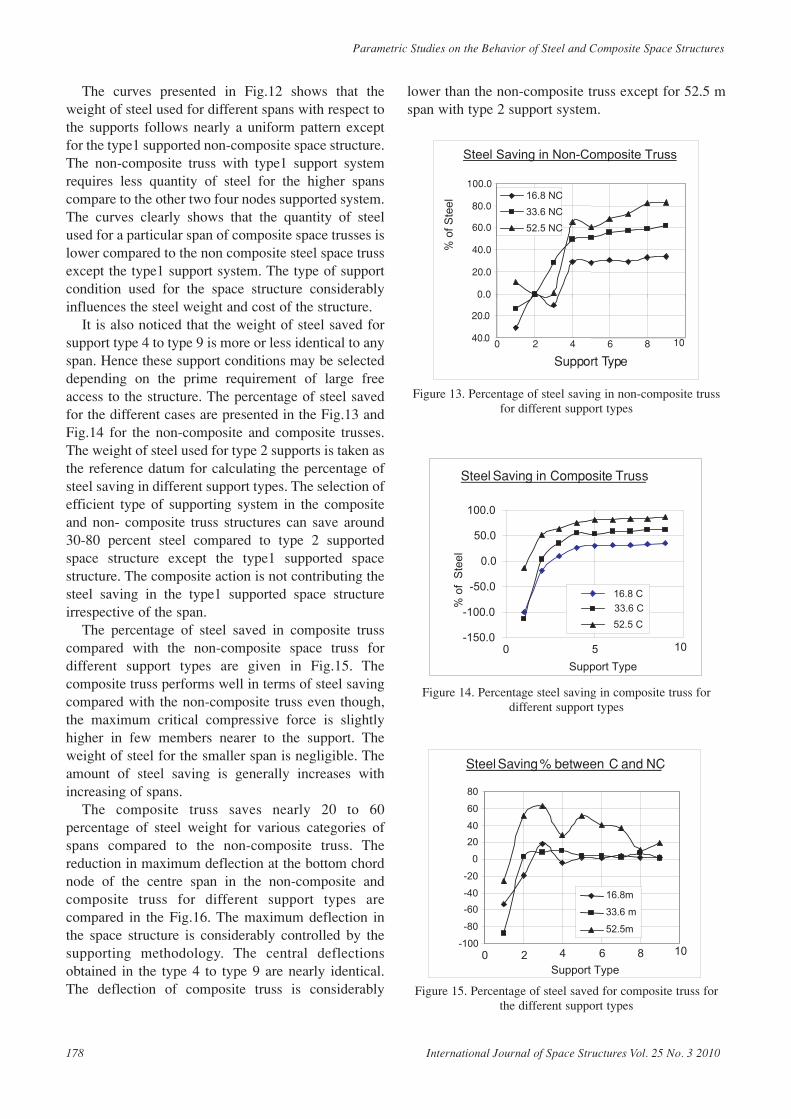
It is also noticed that the weight of steel saved forsupport type 4 to type 9 is more or less identical to anyspan. Hence these support conditions may be selecteddepending on the prime requirement of large freeaccess to the structure. The percentage of steel savedfor the different cases are presented in the Fig.13 andFig.14 for the non-composite and composite trusses.The weight of steel used for type 2 supports is taken asthe reference datum for calculating the percentage ofsteel saving in different support types. The selection ofefficient type of supporting system in the compositeand non- composite truss structures can save around30-80 percent steel compared to type 2 supportedspace structure except the type1 supported spacestructure. The composite action is not contributing thesteel saving in the type1 supported space structureirrespective of the span.
The percentage of steel saved in composite trusscompared with the non-composite space truss fordifferent support types are given in Fig.15. Thecomposite truss performs well in terms of steel savingcompared with the non-composite truss even though,the maximum critical compressive force is slightlyhigher in few members nearer to the support. Theweight of steel for the smaller span is negligible. Theamount of steel saving is generally increases withincreasing of spans.
The composite truss saves nearly 20 to 60percentage of steel weight for various categories ofspans compared to the non-composite truss. Thereduction in maximum deflection at the bottom chordnode of the centre span in the non-composite andcomposite truss for different support types arecompared in the Fig.16. The maximum deflection inthe space structure is considerably controlled by thesupporting methodology. The central deflectionsobtained in the type 4 to type 9 are nearly identical.The deflection of composite truss is considerably
lower than the non-composite truss except for 52.5 mspan with type 2 support system.
Figure 13. Percentage of steel saving in non-composite trussfor different support types
Figure 14. Percentage steel saving in composite truss fordifferent support types
Figure 15. Percentage of steel saved for composite truss forthe different support types
Steel Saving % between C and NC
-100 -80
-60
-40
-20
0
20
40
60
80
0 2 4 6 8 10
Support Type
16.8m 33.6 m 52.5m
Steel Saving in Composite Truss
-150.0
-100.0
-50.0
0.0
50.0
100.0
0 5
% o
f S
teel
16.8 C
33.6 C
52.5 C
Support Type
10
Steel Saving in Non-Composite Truss
40.0
20.0
0.0
20.0
40.0
60.0
80.0
100.0
0 2 4 6 8
Support Type
% o
f S
teel
16.8 NC
33.6 NC
52.5 NC
10
178 International Journal of Space Structures Vol. 25 No. 3 2010
Parametric Studies on the Behavior of Steel and Composite Space Structures
Lakshmikandhan K N, Senthil R, Arul Jayachandran S, Sivakumar P and Ravichandran R
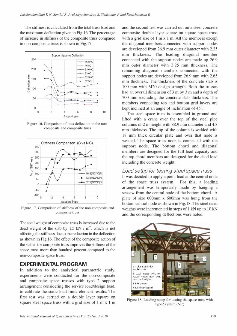
The stiffness is calculated from the total truss load andthe maximum deflection given in Fig.16. The percentageof increase in stiffness of the composite truss comparedto non-composite truss is shown in Fig.17.
Figure 16. Comparison of max deflection in the non-composite and composite truss
Figure 17. Comparison of stiffness of the non-composite andcomposite truss
The total weight of composite truss is increased due to thedead weight of the slab by 1.5 kN / m2, which is notaffecting the stiffness due to the reduction in the deflectionas shown in Fig.16. The effect of the composite action ofthe slab in the composite truss improves the stiffness of thespace truss more than hundred percent compared to thenon-composite space truss.
EXPERIMENTAL PROGRAM In addition to the analytical parametric study,experiments were conducted for the non-compositeand composite space trusses with type 2 supportarrangement considering the service load/design load,to calibrate the static load finite element results. Thefirst test was carried on a double layer square onsquare steel space truss with a grid size of 1 m x 1 m
and the second test was carried out on a steel concretecomposite double layer square on square space trusswith a grid size of 1 m x 1 m. All the members exceptthe diagonal members connected with support nodesare developed from 26.9 mm outer diameter with 2.35mm thickness. The leading diagonal memberconnected with the support nodes are made up 26.9mm outer diameter with 3.25 mm thickness. Theremaining diagonal members connected with thesupport nodes are developed from 26.9 mm with 2.65mm thickness. The thickness of the concrete slab is100 mm with M20 design strength. Both the trusseshad an overall dimension of 3 m by 3 m and a depth of700 mm excluding the concrete slab thickness. Themembers connecting top and bottom grid layers arekept inclined at an angle of inclination of 45°.
The steel space truss is assembled in ground andlifted with a crane over the top of the steel pipecolumns of 2 m height with 88.9 mm diameter and 4.8mm thickness. The top of the column is welded with18 mm thick circular plate and over that node iswelded. The space truss node is connected with thesupport node. The bottom chord and diagonalmembers are designed for the full load capacity andthe top chord members are designed for the dead loadincluding the concrete weight.
Load setup for testing steel space trussIt was decided to apply a point load at the central nodeof the space truss system. For this, a loadingarrangement was temporarily made by hanging aseesaw from the central node of the bottom chord. Aplate of size 600mm x 600mm was hung from thebottom central node as shown in Fig.18. The steel deadweights were incremented in steps of 1 kN up to 10 kNand the corresponding deflections were noted.
Figure 18. Loading setup for testing the space truss withtype2 system (NC)
10-100
Stiffness Comparison (C vs NC)
-50
0
50
100
150
200
250
300
350
0 2 4 6 8
Support Type
% o
f Stif
fnes
s
16.8(NC^C)%
33.6(NC^C)%
52.5(NC^C)%
Support type vs Deflection
0
50
100
150
200
250
0 2 4 6 8 10
Support type
De
flect
ion,
mm
16.8NC
16.8C
33.6NC
33.6C
52.5NC
52.5C
International Journal of Space Structures Vol. 25 No. 3 2010 179
Load setup for testing steel concretecomposite space trussThe top chord members are replaced with a underdesigned minimal section and the composite truss istested for a uniformly distributed load (udl). Forapplying the udl a 1.2 meter height water tank isconstructed above the concrete slab.
The water is constructed with the brick masonrywall of 230 mm thickness. The overall internal size ofthe water tank is 2.7 m x 2.7 m length and 1.2 mheight. The tank is marked at each of the 100 mmheight for measuring the weight of water. Thecomposite space truss and the water tank for loadingare shown in Fig.19.
The water filled in the tank in an increment of 100mm water height as shown in Fig.20 andcorrespondingly the load is incremented with theincrease of 1 kN / m2 which is equal to total load of7.29 kN. The load is increased in twelve steps up to 1.2m and correspondingly the deflections were noted inthe dial gauges at the central and adjacent nodes of thecomposite truss.
Figure 19. Loading setup for testing the composite truss withtype 2 support system (C)
Figure 20. Application of uniformly distributed load over thecomposite space truss
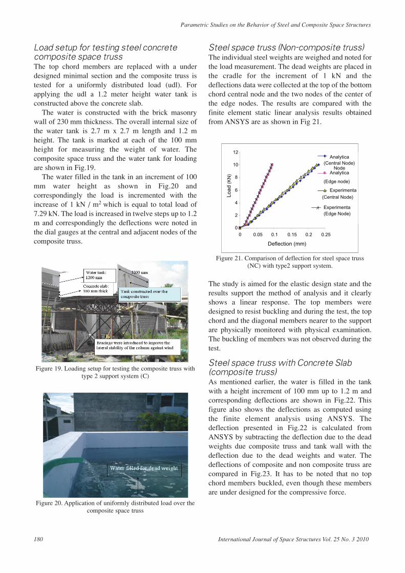
Steel space truss (Non-composite truss)The individual steel weights are weighed and noted forthe load measurement. The dead weights are placed inthe cradle for the increment of 1 kN and thedeflections data were collected at the top of the bottomchord central node and the two nodes of the center ofthe edge nodes. The results are compared with thefinite element static linear analysis results obtainedfrom ANSYS are as shown in Fig 21.
Figure 21. Comparison of deflection for steel space truss(NC) with type2 support system.
The study is aimed for the elastic design state and theresults support the method of analysis and it clearlyshows a linear response. The top members weredesigned to resist buckling and during the test, the topchord and the diagonal members nearer to the supportare physically monitored with physical examination.The buckling of members was not observed during thetest.
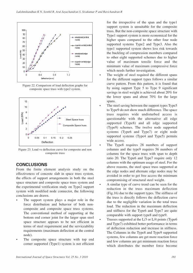
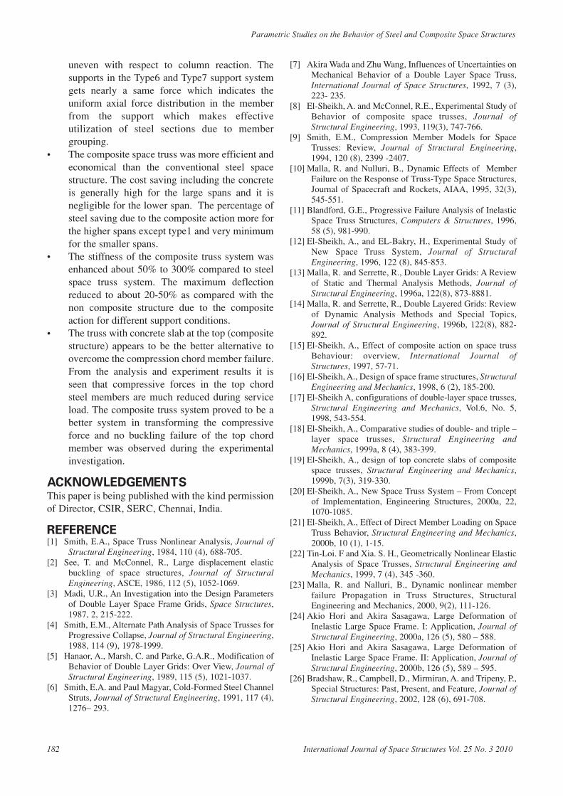
Steel space truss with Concrete Slab(composite truss)As mentioned earlier, the water is filled in the tankwith a height increment of 100 mm up to 1.2 m andcorresponding deflections are shown in Fig.22. Thisfigure also shows the deflections as computed usingthe finite element analysis using ANSYS. Thedeflection presented in Fig.22 is calculated fromANSYS by subtracting the deflection due to the deadweights due composite truss and tank wall with thedeflection due to the dead weights and water. Thedeflections of composite and non composite truss arecompared in Fig.23. It has to be noted that no topchord members buckled, even though these membersare under designed for the compressive force.
0
2
4
6
8
10
12
0 0.05 0.1 0.15 0.2 0.25
Deflection (mm)
Load
(K
N)
Analytica(Central Node)
NodeAnalytica
(Edge node)
Experimenta
(Central Node)
Experimenta(Edge Node)
180 International Journal of Space Structures Vol. 25 No. 3 2010
Parametric Studies on the Behavior of Steel and Composite Space Structures
Lakshmikandhan K N, Senthil R, Arul Jayachandran S, Sivakumar P and Ravichandran R
Figure 22. Comparison of load deflection graphs forcomposite space truss with type2 system.
Figure 23. Load vs deflection curve for composite and noncomposite truss
CONCLUSIONSFrom the finite element analysis study on theeffectiveness of concrete slab in space truss system,the effects of support arrangements in both the steelspace structure and composite space truss system andthe experimental verification study on Type2 supportsystem with modified node connector, the followingconclusions are drawn.• The support system plays a major role in the
force distribution and behavior of both non-composite and composite space truss systems.The conventional method of supporting at thebottom end corner joint for the larger span steelspace structure appears to be not efficient interms of steel requirement and the serviceabilityrequirements (maximum deflection at the centralnode).
• The composite space structure with top endcorner supported (Type1) system is not efficient
for the irrespective of the span and the type1support system is unsuitable for the compositetruss. But the non-composite space structure withType1 support system is more economical for thehigher spans compared to the other four nodesupported systems Type2 and Type3. Also thetype1 supported system shows less risk towardsthe buckling of compression members comparedto other eight supported schemes due to highervalue of maximum tensile force and theminimum value of maximum compressive forcewhich needs further investigation.
• The weight of steel required the different spansfor the different support types follows a similarcurve pattern. From this pattern, it is found thatby using support Type 5 to Type 9 significantsavings in steel weight is achieved about 20% forthe lower spans and about 70% for the largespans.
• The steel saving between the support types Type5to Type9 do not show much difference. The spacetruss requires wide undisturbed access isquestionable with the alternative all edgesupported (Type8) and all edge supported(Type9) schemes. The twelve node supportedsystems (Type6 and Type7) or eight nodesupported systems (Type4 and Type5) permitswide access.
• The Type8 requires 28 numbers of supportcolumns and the type9 requires 56 numbers ofcolumns for the space truss with span to depthratio 20. The Type6 and Type7 require only 12columns with the optimum usage of steel. For theabove reasons, the steel space truss supported atthe edge nodes and alternate edge nodes may beavoided in order to get free access the minimumcompromising of structural steel weight.
• A similar type of curve trend can be seen for thereduction in the truss maximum deflection(Fig.16) due to the support types. The stiffness ofthe truss is directly follows the deflection curvedue to the negligible variation in the total trussload. The reduction in the maximum deflectionand stiffness for the Type6 and Type7 are quitecomparable with support type8 and type9.
• Trusses supported at the L/3 or L/4 points (Type6and Type7) exhibited better performance in termsof deflection reduction and increase in stiffness.The Columns in the Type8 and Type9 supportedsystems, few columns are get more reaction forceand few columns are get minimum reaction forcewhich distributes the member force become
International Journal of Space Structures Vol. 25 No. 3 2010 181
uneven with respect to column reaction. Thesupports in the Type6 and Type7 support systemgets nearly a same force which indicates theuniform axial force distribution in the memberfrom the support which makes effectiveutilization of steel sections due to membergrouping.
• The composite space truss was more efficient andeconomical than the conventional steel spacestructure. The cost saving including the concreteis generally high for the large spans and it isnegligible for the lower span. The percentage ofsteel saving due to the composite action more forthe higher spans except type1 and very minimumfor the smaller spans.
• The stiffness of the composite truss system wasenhanced about 50% to 300% compared to steelspace truss system. The maximum deflectionreduced to about 20-50% as compared with thenon composite structure due to the compositeaction for different support conditions.
• The truss with concrete slab at the top (compositestructure) appears to be the better alternative toovercome the compression chord member failure.From the analysis and experiment results it isseen that compressive forces in the top chordsteel members are much reduced during serviceload. The composite truss system proved to be abetter system in transforming the compressiveforce and no buckling failure of the top chordmember was observed during the experimentalinvestigation.
ACKNOWLEDGEMENTSThis paper is being published with the kind permissionof Director, CSIR, SERC, Chennai, India.
REFERENCE[1] Smith, E.A., Space Truss Nonlinear Analysis, Journal of
Structural Engineering, 1984, 110 (4), 688-705.[2] See, T. and McConnel, R., Large displacement elastic
buckling of space structures, Journal of StructuralEngineering, ASCE, 1986, 112 (5), 1052-1069.
[3] Madi, U.R., An Investigation into the Design Parametersof Double Layer Space Frame Grids, Space Structures,1987, 2, 215-222.
[4] Smith, E.M., Alternate Path Analysis of Space Trusses forProgressive Collapse, Journal of Structural Engineering,1988, 114 (9), 1978-1999.
[5] Hanaor, A., Marsh, C. and Parke, G.A.R., Modification ofBehavior of Double Layer Grids: Over View, Journal ofStructural Engineering, 1989, 115 (5), 1021-1037.
[6] Smith, E.A. and Paul Magyar, Cold-Formed Steel ChannelStruts, Journal of Structural Engineering, 1991, 117 (4),1276– 293.
[7] Akira Wada and Zhu Wang, Influences of Uncertainties onMechanical Behavior of a Double Layer Space Truss,International Journal of Space Structures, 1992, 7 (3),223- 235.
[8] El-Sheikh, A. and McConnel, R.E., Experimental Study ofBehavior of composite space trusses, Journal ofStructural Engineering, 1993, 119(3), 747-766.
[9] Smith, E.M., Compression Member Models for SpaceTrusses: Review, Journal of Structural Engineering,1994, 120 (8), 2399 -2407.
[10] Malla, R. and Nulluri, B., Dynamic Effects of MemberFailure on the Response of Truss-Type Space Structures,Journal of Spacecraft and Rockets, AIAA, 1995, 32(3),545-551.
[11] Blandford, G.E., Progressive Failure Analysis of InelasticSpace Truss Structures, Computers & Structures, 1996,58 (5), 981-990.
[12] El-Sheikh, A., and EL-Bakry, H., Experimental Study ofNew Space Truss System, Journal of StructuralEngineering, 1996, 122 (8), 845-853.
[13] Malla, R. and Serrette, R., Double Layer Grids: A Reviewof Static and Thermal Analysis Methods, Journal ofStructural Engineering, 1996a, 122(8), 873-8881.
[14] Malla, R. and Serrette, R., Double Layered Grids: Reviewof Dynamic Analysis Methods and Special Topics,Journal of Structural Engineering, 1996b, 122(8), 882-892.
[15] El-Sheikh, A., Effect of composite action on space trussBehaviour: overview, International Journal ofStructures, 1997, 57-71.
[16] El-Sheikh, A., Design of space frame structures, StructuralEngineering and Mechanics, 1998, 6 (2), 185-200.
[17] El-Sheikh A, configurations of double-layer space trusses,Structural Engineering and Mechanics, Vol.6, No. 5,1998, 543-554.
[18] El-Sheikh, A., Comparative studies of double- and triple –layer space trusses, Structural Engineering andMechanics, 1999a, 8 (4), 383-399.
[19] El-Sheikh, A., design of top concrete slabs of compositespace trusses, Structural Engineering and Mechanics,1999b, 7(3), 319-330.
[20] El-Sheikh, A., New Space Truss System – From Conceptof Implementation, Engineering Structures, 2000a, 22,1070-1085.
[21] El-Sheikh, A., Effect of Direct Member Loading on SpaceTruss Behavior, Structural Engineering and Mechanics,2000b, 10 (1), 1-15.
[22] Tin-Loi. F and Xia. S. H., Geometrically Nonlinear ElasticAnalysis of Space Trusses, Structural Engineering andMechanics, 1999, 7 (4), 345 -360.
[23] Malla, R. and Nalluri, B., Dynamic nonlinear memberfailure Propagation in Truss Structures, StructuralEngineering and Mechanics, 2000, 9(2), 111-126.
[24] Akio Hori and Akira Sasagawa, Large Deformation ofInelastic Large Space Frame. I: Application, Journal ofStructural Engineering, 2000a, 126 (5), 580 – 588.
[25] Akio Hori and Akira Sasagawa, Large Deformation ofInelastic Large Space Frame. II: Application, Journal ofStructural Engineering, 2000b, 126 (5), 589 – 595.
[26] Bradshaw, R., Campbell, D., Mirmiran, A. and Tripeny, P.,Special Structures: Past, Present, and Feature, Journal ofStructural Engineering, 2002, 128 (6), 691-708.
182 International Journal of Space Structures Vol. 25 No. 3 2010
Parametric Studies on the Behavior of Steel and Composite Space Structures
Lakshmikandhan K N, Senthil R, Arul Jayachandran S, Sivakumar P and Ravichandran R
[27] Fulop, A. and Ivanyi, M., Experimentally analyzedstability and ductility behaviour of a space-truss roofsystem, Thin-Walled Structures, 2004, 42, 309–320.
[28] Lakshmikandhan, K.N., Senthil, R. and Jatin, E.,Comparative Study on steel Space Frame Structures withDifferent Angle of Inclinations, National Conference for
Research Scholars, ACE, Hosur, India, 2005.[29] Lakshmikandhan, K.N., Senthil, R., Arul Jayachandran,
S., Sivakumar, P. and Ravichandran, R., Study on theEffect of Concrete Slab Thickness on the Behaviour ofSteel Space Structure, Steel in Construction, INSDAG,2009, 10 (1), 1-12.
International Journal of Space Structures Vol. 25 No. 3 2010 183

Related Documents