Multi-Pultrusion Fibre Composite Truss Systems for Deployable Shelters By Tarek Omar Supervised by Prof. Gerard Van Erp Assoc. Prof. Thiru Aravinthan Dr. Tim Heldt A dissertation submitted for the award of DOCTOR OF PHILOSOPHY Centre of Excellence in Engineered Fibre Composites Faculty of Engineering & Surveying University of Southern Queensland Queensland, Australia March 2008

Welcome message from author
This document is posted to help you gain knowledge. Please leave a comment to let me know what you think about it! Share it to your friends and learn new things together.
Transcript
Multi-Pultrusion Fibre Composite Truss Systems for
Deployable Shelters
By
Tarek Omar
Supervised by
Prof. Gerard Van Erp
Assoc. Prof. Thiru Aravinthan
Dr. Tim Heldt
A dissertation submitted for the award of
DOCTOR OF PHILOSOPHY
Centre of Excellence in Engineered Fibre Composites
Faculty of Engineering & Surveying
University of Southern Queensland
Queensland, Australia
March 2008

Multi-Pultrusion Fibre Composite Truss Systems for Deployable Shelters i
Abstract
Deployable shelters of various forms have been utilized since ancient civilization.
The need for these systems has not diminished over time and development continues
for military forces, civilian humanitarian aid, and natural disaster scenarios. Recent
developments have focused mainly on tent-type structures, air-beam technology and
steel frames supporting soft fabric; yet none of these have fully satisfied the
deployability requirements. The Military Modular Shelter System (M2S2) initiative is
a research project with the University of Southern Queensland that aims to develop a
fibre composite re-deployable arched shelter system with rigid PVC or fabric
cladding. The main frames are formed from modular fibre composite truss panels
that are connected and stressed into position by prestressing cables. Flexibility in
defining the geometry of frames constructed by using this system is achieved by
changing the number of panels per frame and the packer sizes between panels.
The current study is the first to investigate a suitable truss system for the M2S2
concept. Accordingly, it was necessary to validate the M2S2 concept by searching the
literature for previously developed deployable shelter concepts and locate the
currently used fibre composite truss systems. Then try to establish a suitable truss
system that fulfils the deployability needs with sound structural performance.
An innovative all-composite truss concept, named Multi-Pultrusion Truss-System
(MPTS), was developed as a result of this study. It overcame the classical difficulty
of joining composite members by loading each component of the truss in its strength
direction. In addition, the system had inherent redundancy that provided alternate
load paths after reaching ultimate capacity. The basic idea of this system was to have
chord and vertical members formed from a few pultrusions of the same size. The
traditional usage of gussets was eliminated by using laminates for the bracing system
which directly connected between the pultrusions. This system allowed direct
ii
transfer of the bracing forces to the connected members (pultrusions). This layout led
to reducing the concentration of stresses in the adhesive layers (due to its continuous
nature), while providing symmetric joints with two double-lap joints. All these
factors contributed to having failure away from the joint area. The confinement of
the bracing system, due to its finite dimensions, was one of the characteristics of this
construction technology.
Two MPTS alternatives were developed, tested and investigated. The first
alternative used a Discrete-Diagonal (DD) bracing system made of sandwich
diagonal. Two panels DI-MPTS panels were tested using this configuration, one with
the diagonals under tension and the other with the diagonals under compression.
The second alternative used a Diaphragm (DI) bracing system. Three different
DI-MPTS panels were investigated. The first panel had an empty diaphragm (no
core); the second panel had a partially-filled sandwich diaphragm while the third
panel had a completely-filled sandwich diaphragm.
To achieve understanding of the basic behaviour of each of these panels, finite
element (FE) analyses were conducted at micro level. The different components of
the panel were included in each model, with idealisations to achieve an efficient
analysis process. The FE analysis results were used to investigate the distribution of
forces in each of the panel components.
Due to the associated costs of micro-model analyses, macro-analysis models are
important tools for engineers interested in modelling this system, conduct pre-micro-
analysis parametric studies and in modelling the overall frame structure. This study
ended with presenting simplified analysis procedures for the different panel types.
The work conducted in this study has revealed that this new fibre composite truss
system suits the characteristics of fibre composites and accordingly provides an
efficient solution for general truss applications. It combines simplicity, easiness of
manufacturing, high-load carrying capacity and structural redundancy. In addition,
its behaviour and failure modes can be accurately predicted by using the currently
available finite element software packages.
Multi-Pultrusion Fibre Composite Truss Systems for Deployable Shelters iii
Certification of Dissertation
I certify that the ideas, experimental work, results, analysis and conclusions
reported in this dissertation are entirely my own effort, except where otherwise
acknowledged. I also certify that the work is original and has not been previously
submitted for any other award, except where otherwise acknowledged.
- - - - - - - - - - - - - - - - - - - - - - - - - / /
Signature of Candidate Date
Endorsed:
- - - - - - - - - - - - - - - - - - - - - - - - - / /
Signature of Supervisor/s Date
- - - - - - - - - - - - - - - - - - - - - - - - - / /
Signature of Supervisor/s Date

iv

Multi-Pultrusion Fibre Composite Truss Systems for Deployable Shelters v
Acknowledgement Putting my name, solely, as the author of this thesis is not quite fair. I was one of
a team and, without the contribution of each member, this work would not be in this
form. Many people in the Centre of Excellence in Engineered Fibre Composites
(CEEFC) and the Faculty of Engineering and Surveying (FOES) made a direct and
indirect contribution in helping me to complete my research work successfully. I
sincerely appreciate the efforts of my supervisors - Prof. Gerard Van Erp, who
introduced me to the world of composite materials in civil engineering, Assoc. Prof.
Thiru Aravinthan for help in testing procedures and prestressing technologies, and
Dr. Tim Heldt for starting the research work in this project. It would have been
difficult to finish this thesis without their continual patience, advice, support and
understanding.
I thank Strarch Australia and Kencana Composites for sponsoring this project and
more specifically Dr. Peter Key who convinced me to join the CEEFC and
supporting my shift to Australia. I thank especially Assoc. Prof. David Buttsworth,
Associate Dean for Research, for his continuous support that facilitated my work
through the different departments. Also, I would like to thank all the technical and
administration staff who worked behind the scenes to support the research work,
Darren Browne, John Ashby, Wayne Crowell, Henk Van Kerkwyk, and all the others
for their valuable advice, innovation and co-operation. The library staff must have a
special appreciation for their efforts to locate references from different destinations.
Ian Mitchell, Ruth Hilton and Jean Althoff were of a great help in editing the text of
the thesis and kept questioning me about the logistics of its contents. And it would be
remiss not to mention the friendly environment we found from the wider community
that made our settlement in Toowoomba quite enjoyable.
I wish to thank my parents for raising me to love my work, my wife who was
very patient for the long time spent alone looking after the family while I was
preparing this thesis and for my kids who missed my company for some time. At the
end I like to thank You, the readers, who spend time in reading this thesis. I trust that
the outcome of the effort of the team who worked in this project will be of a good
value to you.

vi
Multi-Pultrusion Fibre Composite Truss Systems for Deployable Shelters vii
Associated Publications
Omar, T., Aravinthan, T., and Van Erp, G. (2007). "Behaviour of sandwich
columns under edgewise compression loading." Asia-Pacific Conference on
FRP in Structures (APFIS 2007), Hong Kong, China.
Omar, T., Heldt, T., Key, P. W., and Van Erp, G. (2005). "Development of
modular deployable composite shelters." Australian Structural Engineering
Conference - ASEC2005, Newcastle City Hall, Newcastle, NSW, Australia.
Omar, T., Van Erp, G., Aravinthan, T., and Key, P. W. (2007). "Innovative all-
composite multi-pultrusion truss system for stressed-arch deployable
shelters." Sixth Alexandria International Conference on Structural &
Geotechnical Engineering (AICSCE 6), Alexandria, Egypt.
Omar, T., Heldt, T., Key, P. W., and Van Erp, G. (2006). "M2S2 Modular
deployable composite shelters - concept and loading criteria." Australian
Journal of Structural Engineering, 6(3), 217-226.
Omar, T., Van Erp, G., Aravinthan, T., and Key, P. W. (2007). "M2S2 modular
deployable shelter system - concept and analysis technique." Structural
Engineering & Construction Conference (ISEC-4), Melbourne, Australia.
Omar, T., Van Erp, G., and Key, P. W. (2007). "Modular deployable composite
shelters - truss system." Proceedings of ACIC 07, Advanced Composites in
Construction, University of Bath, Bath, UK.
Omar, T., Van Erp, G., and Key, P. W. (2006). "Stressed-arch modular
deployable composite shelters, concept and development." Third
International Conference on FRP Composites in Civil Engineering (CICE
2006), Miami, Florida, USA.

viii Table of Contents
Multi-Pultrusion Fibre Composite Truss Systems for Deployable Shelters ix
Table of Contents List of Figures xv List of Tables xxi
CHAPTER 1 Introduction 1.1 Introduction 1
1.2 Background 2 1.3 The Concept of M2S2 4
1.4 M2S2 - Main Components 6 1.5 Objectives of the Study 7
1.6 Outline of the Thesis 8 1.7 Summary 11
1.8 References 11
CHAPTER 2 Deployable Shelters and Fibre Composite Trusses- State of the Art
2.1 General 13 2.2 Deployable Shelters Performance Criteria 13
2.3 Modern Deployable Shelters - Review 14 2.3.1 Pantograph Type Structures 15
2.3.2 Air-Inflated Shelters 16
2.3.2.1 M-51 Air-Supported Shelter
2.3.2.2 Battalion Aid Station Air-Supported Shelter
2.3.2.3 High-Pressure Air-Supported Shelter
2.3.3 Rigid Frames Supporting Soft Fabric Shelter 18
2.3.3.1 Battalion Aid Station Frame-Supported Shelter
2.3.3.2 Expeditionary Aircraft Maintenance Hanger
2.3.3.3 WideSpan Frame-Supported Shelter
2.3.3.4 Extra Large Deployable Aircraft Hanger
2.3.4 Tent Shelters 20
2.4 Fibre Composite Truss Systems 21 2.4.1 Trusses Made of Pultrusions 21
2.4.2 Bridge Decks with Truss Form 22
2.4.3 Monocoque Fibre Composite Truss 22
2.4.4 Fibre Composite Truss with Snap-Joint 23
2.4.5 Modular Composite Truss Panels 24
x Table of Contents
2.5 Conclusions 25
2.6 References 26
CHAPTER 3 Behaviour of Discrete-Diagonal, Multi- Pultrusion Truss Systems
3.1 General 29
3.2 Adhesively Bonded Pultrusion / PFR Truss System (Panel: P109) 30 3.2.1 P109 - Concept 30
3.2.2 P109 - Panel Manufacturing 31
3.2.3 P109 - Panel Evaluation 32
3.2.4 Important Parameters for the Panel System 32
3.3 Discrete-Diagonal, Multi-Pultrusion Truss System (DD-MPTS) – Concept Development 33
3.3.1 DD-MPTS - Concept 34
3.3.2 DD-MPTS Joint (P209) Manufacturing and Materials Used 35
3.3.3 DD-MPTS Joint (P209) Behaviour 38
3.3.4 DD-MPTS – The Updated Concept 40
3.4 Development of the Updated Discrete-Diagonal, Multi-Pultrusion
Truss System (Panel: P309) 41 3.4.1 P309 - Materials Used 41
3.4.2 P309 - Panel Manufacturing 42
3.5 P309 - FE Modelling 44 3.5.1 Modelling Pultrusions 45
3.5.2 Modelling Diagonals 47
3.5.3 Modelling Adhesive Layers 49
3.5.4 P309 - Modelling Options 49
3.6 P309 - Test and FE Results 50 3.6.1 P309 - Experimental Observations and FE Model Verifications 53
3.6.1.1 Test Observations
3.6.1.2 Performance of the FE Model
3.6.2 P309 - Behaviour 56
3.6.2.1 P309 – Behaviour of the Diagonals
3.6.2.2 P309 – Behaviour of the Pultrusions
3.6.2.3 P309 – Behaviour of the Adhesive Layers
3.6.2.4 P309 – Behaviour of the Gussets
3.6.2.5 P309 – General Behaviour
3.7 Conclusions 74
3.8 References 76
Multi-Pultrusion Fibre Composite Truss Systems for Deployable Shelters xi
CHAPTER 4 Behaviour of Sandwich Members under Axial Loads – Application for Discrete-Diagonal, Multi-Pultrusion Truss System
4.1 General 79
4.2 Pre-investigations of Sandwich Prototype Columns 81 4.2.1 Sample Preparations and Testing Procedures 81
4.2.2 Test Results 83
4.3 Development of Sandwich Structures 85 4.4 Behaviour of Sandwich Panels - Review 87
4.4.1 Sandwich Columns Failure Modes 87
4.4.2 Predicting the Capacity of Sandwich Columns 89
4.4.2.1 Overall Buckling Capacity (due to bending and shear)
4.4.2.2 Face Plastic Micro-Buckling Capacity
4.4.2.3 Face Wrinkling Capacity
4.4.2.4 Failure Predictions in Composite Materials
4.5 Single-Core Prototype Columns Testing Program 96 4.5.1 Specimen Preparations 97
4.5.2 Characterisation of the Core Materials 98
4.5.3 Test Set-Up and Observations 100
4.5.4 FE Modelling 102
4.5.5 Verification of the FE Model for the T02-01 Column 104
4.5.6 Verification of the FE Model for the T02-06 Column 106
4.6 Behaviour of DD-MPTS with Diagonals in Compression (Panel: P409) 114
4.6.1 P409 - Panel Manufacturing 114
4.6.2 P409 - FE Modelling 115
4.6.3 P409 - Test Observations & FE Results 116
4.7 Conclusions 121 4.8 References 122
CHAPTER 5 Behaviour of Diaphragm, Multi-Pultrusion Truss Systems (DI-MPTS)
5.1 General 127
5.2 Development of the Diaphragm, Multi-Pultrusion Truss System (Panel: P509) 128
5.2.1 P509 - Materials Used 129
5.2.2 P509 – Panel Manufacturing 129
xii Table of Contents
5.2.3 P509 - Test Results and Evaluation 130
5.3 Development of an Updated Diaphragm, Multi-Pultrusion Truss
System (Panel: P609) 132 5.3.1 P609 - Test Set-Up 132
5.3.2 P609 - FE Modelling 133
5.3.3 P609 - Test and FE Results 135
5.3.4 P609 - Experimental Observations and FE Model Verifications 137
5.3.4.1 Test Observations
5.3.4.2 Performance of the FE Models
5.3.5 P609 - Behaviour 141
5.3.5.1 P609 – Behaviour of the Diaphragms
5.3.5.2 P609 – Behaviour of the Pultrusions
5.3.5.3 P609 – Behaviour of the Adhesive Layers
5.3.5.4 P609 – General Behaviour
5.4 Sandwich-Diaphragm, Multi-Pultrusion Truss Systems
(Panel: P709 and P809) 148 5.4.1 P709 and P809 – Panel Manufacturing 149
5.4.2 Modelling Options 152
5.4.3 P709 - Test and FE Results 152
5.4.4 P709 - Experimental Observations and FE Model Verifications 153
5.4.4.1 Test Observations
5.4.4.2 Performance of the FE Model
5.4.5 P809 - Test and FE Results 155
5.4.6 P809 - Experimental Observations and FE Model Verifications 156
5.4.6.1 Test Observations
5.4.6.2 Performance of the FE Model
5.4.7 P709 and P809 - Behaviour 156
5.4.7.1 P709 and P809 – Behaviour of the Diaphragms
5.4.7.2 P709 and P809 – Behaviour of the Pultrusions
5.4.7.3 P709 and P809 – Behaviour of the Adhesive Layers
5.4.7.4 P709 and P809 – General Behaviour
5.5 Multi-Pultrusion Truss Systems - Comparing the Discrete-
Diagonal and Diaphragm Systems 166 5.5.1 Structural Performance 167
5.5.2 Panel Costs 167
5.5.3 Panel Weights 168
5.6 Conclusions 169 5.7 References 169
Multi-Pultrusion Fibre Composite Truss Systems for Deployable Shelters xiii
CHAPTER 6 Simplified Analysis Models for the Multi-Pultrusion Truss Systems (MPTS)
6.1 Introduction 171 6.2 Important Simplified Model Components 172
6.3 P409 - Macro Model Concepts, Analysis Results and Discussions 173 6.3.1 P409 - Macro Model 173
6.3.2 P409 - Macro Model Results 175
6.3.3 P409 - Macro Model Discussions 177
6.4 P809 - Macro Model Concepts, Analysis Results and Discussions 179 6.4.1 P809 - Macro Model 179
6.4.2 P809 - Macro Model Results 180
6.4.3 P809 - Macro Model Discussions 181
6.5 Conclusions 181
6.6 References 181
CHAPTER 7 Conclusions and Suggestions for Further Research Work
7.1 Introduction 183
7.2 Structural Systems for Composite Trusses 184 7.3 Modelling Considerations of the MPTS 186
7.3.1 FE Micro Model 186
7.3.2 FE Macro Model 187
7.4 General Conclusions 188
7.5 Suggestions for Further Research Work 189
Bibliography 193 Appendix A Assessing Loads on Deployable Shelters
A.1 Introduction A-1
A.2 Wind Data in Loading Codes A-2 A.3 Wind Loading on Deployable Shelters A-4
A.4 Wind Pressures on M2S2 Using AS/NZS 1170.2 (2002) & ASCE 7-95 (1996) A-6
A.4.1 Using AS/NZS 1170.2 (2002) A-6
A.4.2 Using ASCE 7-95 (1996) A-7
A.4.3 General Comments A-7
xiv Table of Contents
A.5 References A-8
Appendix B M2S2 Analysis Procedures B.1 Introduction B-1
B.2 Structural analysis of M2S2 shelter Frames B-1 B.2.1 Model Development B-1
B.2.2 Applying Loads B-5
B.3 Discussions of the Analysis Results B-6
B.4 References B-8
Appendix C Sandwich Columns with Mixed-Cores - Test Results
C.1 Introduction C-1 C.2 Columns Specimen Preparations and Testing Procedures C-2
C.3 Test Records and Observations C-4 C.4 Discussion of the Behaviour of the Mixed-Core Columns C-9
C.5 References C-10
Appendix D: Double-Bay DD-MPTS - Test Results
D.1 Introduction D-1
D.2 Test Records D-4 D.2.1 Prestressing Process D-4
D.2.2 Dynamic Test D-5
D.2.2 Static Test to Failure D-6
D.3 Test Observations and Comments D-8
D.4 References D-10
Multi-Pultrusion Fibre Composite Truss Systems for Deployable Shelters xv
List of Figures
CHAPTER 1 Introduction Figure Figure Title Sec. Page 1.1 Strarch conventional shelters during erection 1.1 1 1.2 Tent in Northern Africa, a deployable shelter system 1.2 2 1.3 Fixing roof sheeting during assembly stage 1.3 5 1.4 Stressing the frames during erection stage 1.3 5 1.5 Deployed shelter system 1.3 5 1.6 M2S2 main components 1.4 6
CHAPTER 2 Deployable Shelters & Fibre Composite Trusses - State of the Art
Figure Figure Title Sec. Page 2.1 Principal of pantograph 2.3.1 16 2.2 M-51 - First deployable shelter system 2.3.2 16 2.3 Braided air beam by Vertigo Inc 2.3.2 17 2.4 Frame supported BAS 2.3.3 18 2.5 Expeditionary Aircraft Maintenance Hangar 2.3.3 19 2.6 Weatherhaven WideSpan shelter system 2.3.3 19 2.7 XLDAHS Shelter during erection 2.3.3 20 2.8 Base X Shelter System by Bea Maurer 2.3.3 20 2.9 Pontresina bridge, Switzerland 2.4.1 21 2.10 Composite trusses for storage reservoir roof at Darvel 2.4.1 22 2.11 EZSpan system 2.4.2 22 2.12 Monocoque Fibre Composite truss concept 2.4.3 23 2.13 MFC concept of strength and fill layers 2.4.3 23 2.14 Assembly of snap-joint 2.4.4 24 2.15 Overhead transmission tower using snap-joint 2.4.4 24 2.16 Interlocking panel concept 2.4.5 24
CHAPTER 3 Behaviour of Discrete-Diagonal, Multi-Pultrusion Truss Systems
Figure Figure Title Sec. Page 3.1 P109 - Panel a) Components and b) Layout 3.2.1 31 3.2 P109 - Casting PFR on the chord members 3.2.2 31 3.3 DD-MPTS - Initial concept 3.3.1 34 3.4 Developing the concept of DD-MPTS from (a) traditional truss
to (b) MPTS 3.3.1 35
3.5 P209 - Bracket (a) dimensions, and (b) test layout 3.3.2 35 3.6 P209 - Failure modes 3.3.3 39 3.7 P209 - Load-displacement curves 3.3.3 39 3.8 DD-MPTS (a) Original and (b) Updated concepts 3.3.4 40 3.9 P309 - Dimensions and test layout 3.4 41 3.10 P309 - Diagonal skins and packers 3.4.1 42 3.11 P309 - Assembling of the first two frames 3.4.2 43
xvi List of Figures
3.12 P309 - Assembling of diagonals 3.4.2 44 3.13 P309 - Assembling the last frame 3.4.2 44 3.14 P309 - Modelling concept and interactions 3.5 45 3.15 Expected errors in representing pultrusions using shell elements 3.5.1 46 3.16 Shell elements definition for the diagonal skins 3.5.2 48 3.17 Assigning solid continuum elements to the diagonal core 3.5.2 49 3.18 P309 – FE model layout 3.5.4 50 3.19 P309 - Strain gauge locations 3.6 51 3.20 P309 - Load-displacement curves 3.6 51 3.21 P309 - SG15 Strain- displacement curves 3.6 51 3.22 P309 - SG18 Strain-displacement curves 3.6 52 3.23 P309 - SG32 Strain-displacement curves 3.6 52 3.24 P309 - SG34 Strain- displacement curves 3.6 52 3.25 P309 - SG37 Strain- displacement curves 3.6 53 3.26 P309 - Failure at ultimate load 3.6.1 54 3.27 P309 - Sway after reaching ultimate capacity 3.6.1 54 3.28 P309 - Final failure 3.6.1 54 3.29 Section definitions for the diagonal member 3.6.2 58 3.30 21-08 - Section forces along section P2 3.6.2 59 3.31 21-08 - Section forces along section P1 3.6.2 59 3.32 21-08 - Section forces along section P4 3.6.2 59 3.33 21-08 - Deformed shape at corners 3.6.2 60 3.34 21-08 - Lateral stresses (S22) 3.6.2 60 3.35 11-01 - Lateral stresses (S22) 3.6.2 61 3.36 Section paths along the pultrusions 3.6.2 62 3.37 21-08 - Section forces along top chord – P5 3.6.2 62 3.38 21-08 - Section forces along top chord – P7 3.6.2 63 3.39 21-08 - Section forces along top chord – P8 3.6.2 63 3.40 21-08 - Section forces along bottom chord – P8 3.6.2 63 3.41 21-08 - Section forces along edge vertical – P5 3.6.2 64 3.42 21-08 - Section forces along edge vertical – P6 3.6.2 64 3.43 21-08 - Section forces along edge vertical – P7 3.6.2 64 3.44 21-08 - Section forces along edge vertical – P8 3.6.2 65 3.45 Principal stress vectors in the top chord 3.6.2 67 3.46 21-08 - Glue section paths layout 3.6.2 67 3.47 21-08 - Glue stresses along path P4 3.6.2 68 3.48 21-08 - Glue stresses along path P5 3.6.2 68 3.49 21-08 - Glue stresses along path P6 3.6.2 68 3.50 21-08 - Glue stresses along path P7 3.6.2 69 3.51 21-08 - Glue stresses along path P8 3.6.2 69 3.52 P309 - Glue fillet 3.6.2 70 3.53 21-08 - Gusset section forces SF1 (vertical) 3.6.2 72 3.54 21-08 - Gusset axial section forces SF2 (horizontal) 3.6.2 72 3.55 21-08 - Gusset shear section forces SF3 3.6.2 72 3.56 21-08 - Gusset (a) Principal stresses and (b) Vectors 3.6.2 73
CHAPTER 4 Behaviour of Sandwich Members under Axial Loads – Application for Discrete-Diagonal, Multi-Pultrusion Truss System
Figure Figure Title Sec. Page 4.1 Patterned pink foam for T01-03 column 4.2.1 83 4.2 Prototype test layout of T01 columns 4.2.1 83 4.3 T01-02 - Failure mode 4.2.2 83
Multi-Pultrusion Fibre Composite Truss Systems for Deployable Shelters xvii
4.4 T01-04 - Failure mode 4.2.2 84 4.5 T01-01 - Failure mode 4.2.2 84 4.6 Beech Starship, the first all-composite sandwich aircraft 4.3 85 4.7 Modes of failure in sandwich panels under edge load - MIL-
HDBK-23 4.4.1 88
4.8 Progressive end-crushing failure mode for sandwich columns 4.4.1 88 4.9 Sandwich column cross-section 4.4.2 90 4.10 Plastic micro-buckling of composites under compression 4.4.2 92 4.11 Measured compressive strength of glass and Kevlar fibre
composites 4.4.2 93
4.12 Gluing skins to the core for single core columns 4.5.1 98 4.13 Characterising core materials a) ASTM C393-00 3-point test, b)
Rocket test 4.5.2 99
4.14 T02 - Columns test setup 4.5.3 100 4.15 T02-01 - Failure mode 4.5.3 101 4.16 T02-06 - Failure modes (a) face micro-buckling, (b) core shear 4.5.3 101 4.17 T02-01 - Solid-shell model layout and EV mode shape 4.5.4 103 4.18 T02-01 - Load-Axial displacement 4.5.5 105 4.19 T02-01 - Horizontal displacement-Load 4.5.5 105 4.20 T02-01 - Maximum strain-Load (on concave face) 4.5.5 106 4.21 T02-01 - Minimum strain-Load (on convex face) 4.5.5 106 4.22 T02-06 - Core patterns for the two failure modes (a) at skins, and
(b) at core 4.5.6 107
4.23 T02-06 - Load-Axial displacement 4.5.6 107 4.24 T02-06 - Horizontal displacement-Load 4.5.6 108 4.25 T02-06 - Maximum strain-Load 4.5.6 108 4.26 T02-06 - Minimum strain-Load 4.5.6 108 4.27 T02-06 - SF1 at bottom skin 4.5.6 109 4.28 T02-06 - SF1 at top skin 4.5.6 110 4.29 T02-06 - SF2 at bottom skin 4.5.6 110 4.30 T02-06 – SF3 at bottom skin 4.5.6 110 4.31 T02-06 - Typical section forces - CSO-R1 4.5.6 113 4.32 P409 - Test layout 4.6.1 115 4.33 P409 - Manufacturing defects 4.6.1 115 4.34 P409 - Eigen-Vector as initial imperfection 4.6.2 116 4.35 P409 - Failure at the lower corner 4.6.3 117 4.36 P409 - Failure at the upper corner 4.6.3 117 4.37 P409 - Load-deflection curves 4.6.3 117 4.38 P409 - Load-strain curves 4.6.3 118 4.39 Predicting the buckling load of sandwich columns 4.6.3 118 4.40 Section forces (SF1, SF2 & SF3) at the diagonal bottom corner 4.6.3 119 4.41 P409 - Load-time curve 4.6.3 119 4.42 Tsai-Wu criterion - Failure index factor at lower corner 4.6.3 121
CHAPTER 5 Behaviour of Diaphragm, Multi-Pultrusion Truss Systems (DI-MPTS)
Figure Figure Title Sec. Page 5.1 P509 - Panel (a) General concept and (b) dimensions 5.2 129 5.2 P509 - Panel during assembly 5.2.2 130 5.3 P509 - Test layout 5.2.3 130 5.4 P509 - Load-displacement curves 5.2.3 131 5.5 P509 - Web buckling during test 5.2.3 132 5.6 P509 - Failure modes 5.2.3 132
xviii List of Figures
5.7 P609 - dimensions and test layout 5.3.1 133 5.8 P609 - FE Model layout 5.3.2 134 5.9 First mode shape using EV analysis for 13-03 run 5.3.2 135 5.10 Imperfection displacement for 13-04 run 5.3.2 135 5.11 P609 - Strain gauge locations 5.3.3 136 5.12 P609 - Load-displacement curves 5.3.3 136 5.13 P609 - SG15 Strain-displacement curves 5.3.3 136 5.14 P609 - SG20 Strain-displacement curves 5.3.3 137 5.15 P609 - SG37 Strain-displacement curves 5.3.3 137 5.16 P609 – Web buckling mode 5.3.4 138 5.17 P609 - Failure mode 5.3.4 139 5.18 P609 - Analysis 13-01 lateral displacement 5.3.4 140 5.19 P609 - Slope of load-displacement curves for FE Analyses 5.3.4 140 5.20 P609 - Initial imperfection effect on load-displacement curves 5.3.4 141 5.21 P609 - Skin paths and local axes 5.3.5 142 5.22 P609 - L_Dia out-of-plane displacement 5.3.5 143 5.23 P609 - X_Dia out-of-plane displacement 5.3.5 143 5.24 P609 - L_Dia longitudinal section forces (SF1) 5.3.5 143 5.25 P609 - L_Dia transverse section forces (SF2) 5.3.5 144 5.26 P609 - X_Dia longitudinal section forces (SF1) 5.3.5 144 5.27 P609 - X_Dia transverse section forces (SF2) 5.3.5 144 5.28 P609 - X_Dia integrated section forces (Nt1) 5.3.5 145 5.29 P609 - Developed shear forces (SF3) at corners 5.3.5 145 5.30 P609 - Section forces along top chord – P5 5.3.5 146 5.31 P609 - Glue stresses along path P6 5.3.5 146 5.32 P609 - Development of the cracks and failure at the diaphragm 5.3.5 147 5.33 Shell forces and moments at node: 1156 5.3.5 148 5.34 Shell forces and moments at node: 1166 5.3.5 148 5.35 P709 - Dimensions and test layout 5.4.1 150 5.36 P809 - Dimensions and test layout 5.4.1 150 5.37 P709 - Panel during manufacturing 5.4.1 151 5.38 P809 - Panel during manufacturing 5.4.1 151 5.39 P709 - Panel during repair 5.4.1 151 5.40 P709 - Load-deflection curves 5.4.3 152 5.41 P709 - Left side strain-load curves 5.4.3 153 5.42 P709 - Right side strain-load curves 5.4.3 153 5.43 P709 with skins buckled and debonded 5.4.4 154 5.44 P709 - Failure at ultimate load 5.4.4 154 5.45 P709 - Extensive damage 5.4.4 155 5.46 P809 - Load-deflection curves 5.4.5 155 5.47 P809 - Strain-load curves 5.4.5 156 5.48 P709 and P809 - L_Dia SF1 and SF2 5.4.7 159 5.49 P709 and P809 - X_Dia SF1 and SF2 5.4.7 160 5.50 P709 and P809 - L_Dia SM1 and SM2 5.4.7 160 5.51 P709 and P809 - L_Dia Nt 5.4.7 160 5.52 P709 and P809 - X_Dia Nt 5.4.7 161 5.53 P709, P809 and P609 - Total diaphragm forces 5.4.7 161 5.54 P709 - Strain-load curves 5.4.7 161 5.55 P709 - Potential locations for debonding 5.4.7 162 5.56 P709 and P809 – Section forces in top pultrusion 2-P5 path 5.4.7 163 5.57 P709 and P809 – Section forces in top pultrusion 2-P7 path 5.4.7 163 5.58 P709 and P809 – Section forces in top pultrusion 2-P8 path 5.4.7 164 5.59 P709 and P809 – Section forces in bottom pultrusion 2-P7 path 5.4.7 164 5.60 P709 and P809 – Section forces in edge vertical pultrusion 2-P7
path 5.4.7 164
Multi-Pultrusion Fibre Composite Truss Systems for Deployable Shelters xix
5.61 P709 and P809 - Inner glue stresses 5.4.7 165 5.62 P709 and P809 - Outer glue stresses 5.4.7 165
CHAPTER 6 Simplified Analysis Models for the Multi-Pultrusion Truss Systems (MPTS)
Figure Figure Title Sec. Page 6.1 Pultrusion cross section 6.2 172 6.2 P409 - Simplified model layout 6.3.1 174 6.3 P409 - Micro and macro models – load-displacement 6.3.2 175 6.4 P409 - Micro and macro models – Dia_M11 stresses 6.3.2 175 6.5 P409 - Micro and macro models – Dia_E22 stresses 6.3.2 176 6.6 P409 - Micro and macro models – Gst_M11 stresses 6.3.2 176 6.7 P409 - Micro and macro models – Gst_M22 stresses 6.3.2 176 6.8 P409 - Micro and macro models – Pul2_T stresses 6.3.2 177 6.9 P409 - Micro and macro models – Pul2_B stresses 6.3.2 177 6.10 P809 - Simplified model layout 6.4.1 179 6.11 P809 - Micro and macro models – load-displacement 6.4.2 180 6.12 P809 - Micro and macro models – Dia_E stresses 6.4.2 180 6.13 P809 - Micro and macro models – Pul2_T stresses 6.4.2 180 6.14 P809 - Micro and macro models – Pul2_B stresses 6.4.2 181
Appendix B M2S2 Analysis Procedures Figure Figure Title Sec. Page B.1 35m frame layout B.2.1 B-2 B.2 Linear FE models - cable connectivity B.2.1 B-3 B.3 Nonlinear FE model components at the bottom chord B.2.1 B-5 B.4 Deflected shape of the frame predicted by LinA 1 B.3 B-7 B.5 Deflected shape of the frame predicted by LinA 2 B.3 B-8 B.6 Deflected shape of the frame predicted by NLinA B.3 B-8
Appendix C Sandwich Columns with Mixed-Cores - Test Results
Figure Figure Title Sec. Page C.1 Mixed-core column by using two core types C.1 C-1 C.2 Mixed-core column by using single core with laminated end-caps C.1 C-2 C.3 Manufacturing of the end caps for T02-02 C.2 C-3 C.4 Mixed-core columns load-displacement C.3 C-5 C.5 Mixed-core columns horizontal displacement-load C.3 C-5 C.6 Mixed-core columns maximum strain-load C.3 C-6 C.7 Mixed-core columns minimum strain-load C.3 C-6 C.8 Effect of using Balsa on column capacity C.3 C-6 C.9 Column T02-02 failure C.3 C-7 C.10 Failure type-1 for two-type mixed-core columns C.3 C-7 C.11 Failure type-2 for two-type mixed-core columns C.3 C-7
Appendix D Double-Bay DD-MPTS - Test Results Figure Figure Title Sec. Page D.1 P819 - Layout D.1 D-2
xx List of Figures
D.2 P819 - Strain gauge locations D.1 D-3 D.3 Prestressed panel with end grips D.2.1 D-4 D.4 Prestressing load-displacement D.2.1 D-4 D.5 Effect of PST on different strain levels D.2.1 D-5 D.6 Dynamic loading patterns D.2.2 D-5 D.7 Temperature change during the last day D.2.2 D-5 D.8 Effect of temperature change on the PST force D.2.2 D-6 D.9 Load-displacement for the beginning and end records D.2.2 D-6 D.10 Prestressing and load-displacement curves D.2.3 D-6 D.11 Load-Hz displacement at middle of the left diagonal D.2.3 D-7 D.12 Left diagonal strain-load curves D.2.3 D-7 D.13 Middle-left diagonal strain-load curves D.2.3 D-7 D.14 Chord strain-load curves D.2.3 D-8 D.15 Verticals strain-load curves D.2.3 D-8 D.16 Out-of-plane displacement due to prestressing D.3 D-10 D.17 P819 - Failure due to shear buckling D.3 D-10

Multi-Pultrusion Fibre Composite Truss Systems for Deployable Shelters xxi
List of Tables
CHAPTER 1 Introduction Table Table Title Sec. Page 1.1 Effect of packer size on the frame geometry 1.4 7
CHAPTER 3 Behaviour of Discrete-Diagonal, Multi -Pultrusion Truss Systems
Table Table Title Sec. Page 3.1 Description of the P209 joint brackets 3.3.2 36 3.2 Characteristics of pultrusions 3.3.2 37 3.3 Characteristics of uni-glass laminates 3.3.2 37 3.4 Characteristics of double-bias laminates 3.3.2 37 3.5 HPR26 adhesive properties 3.3.2 38 3.6 Characteristics of Barakoda foam 3.4.1 42 3.7 Material properties of pultrusions 3.5.1 46 3.8 P309 - FE analyses performance 3.6 50 3.9 Tsai-Wu failure index factors 3.6.2 60 3.10 21-08 - Shear force distribution between pultrusion webs 3.6.2 66
CHAPTER 4 Behaviour of Sandwich Members under Axial Loads – Application for Discrete-Diagonal, Multi-Pultrusion Truss System
Table Table Title Sec. Page 4.1 Slenderness of prototype columns 4.2.1 81 4.2 T01 - Column capacities 4.2.2 84 4.3 Characteristics of core materials 4.5.2 99 4.4 T02 - Single-core columns strength & stiffness 4.5.3 101 4.5 T01-01 - Summary of predicted failure capacities 4.5.5 104 4.6 T02-06 - FE analysis parameters 4.5.6 109 4.7 T02-06 - Summary of predicted failure capacities 4.5.6 109
CHAPTER 5 Behaviour of Diaphragm, Multi-Pultrusion Truss Systems (DI-MPTS)
Table Table Title Sec. Page 5.1 P609 - FE analyses parameters 5.3.3 137 5.2 Comparison of panel weights 5.5.3 168
CHAPTER 6 Simplified Analysis Models for the Multi-Pultrusion Truss Systems (MPTS)
Table Table Title Sec. Page 6.1 P409 - Micro and macro models analysis time (s) 6.3.3 178
xxii List of Tables
Appendix A Assessing Loads on Deployable Shelters Table Table Title Sec. Page A.1 Wind Pressures Calculations – AS/NZS 1170.2 (2002) A.4.1 A-6 A.2 Wind Pressures Calculations – ASCE 7-95 (1996) A.4.2 A-7
Appendix B M2S2 Analysis Procedures Table Table Title Sec. Page B.1 Material properties used in frame analysis B.2.1 B-2 B.2 Analysis Results B.2.2 B-6
Appendix C Sandwich Columns with Mixed-Cores - Test Results Table Table Title Sec. Page C.1 Mixed-core column geometries C.1 C-2 C.2 Mixed-core columns capacities and specific strength C.3 C-5 C.3 Mixed-core columns stiffness C.3 C-5
1.1 Introduction
Chapter 1: Introduction
1
1. Introduction
1.1. INTRODUCTION
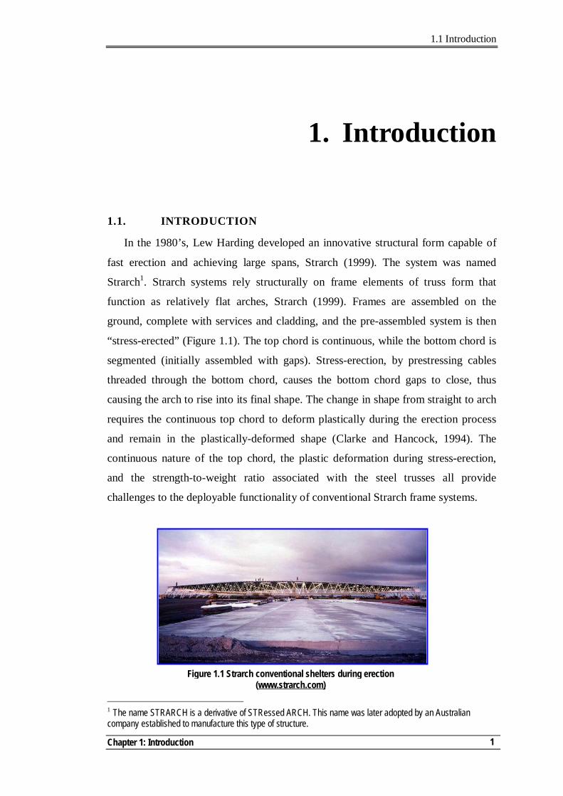
In the 1980’s, Lew Harding developed an innovative structural form capable of
fast erection and achieving large spans, Strarch (1999). The system was named
Strarch1. Strarch systems rely structurally on frame elements of truss form that
function as relatively flat arches, Strarch (1999). Frames are assembled on the
ground, complete with services and cladding, and the pre-assembled system is then
“stress-erected” (Figure 1.1). The top chord is continuous, while the bottom chord is
segmented (initially assembled with gaps). Stress-erection, by prestressing cables
threaded through the bottom chord, causes the bottom chord gaps to close, thus
causing the arch to rise into its final shape. The change in shape from straight to arch
requires the continuous top chord to deform plastically during the erection process
and remain in the plastically-deformed shape (Clarke and Hancock, 1994). The
continuous nature of the top chord, the plastic deformation during stress-erection,
and the strength-to-weight ratio associated with the steel trusses all provide
challenges to the deployable functionality of conventional Strarch frame systems.
1 The name STRARCH is a derivative of STRessed ARCH. This name was later adopted by an Australian company established to manufacture this type of structure.
Figure 1.1 Strarch conventional shelters during erection (www.strarch.com)
1.1 Introduction
Multi-Pultrusion Fibre Composite Truss Systems for Deployable Shelters
2
In 2003, Strarch proposed the utilisation of fibre composites, as a construction
material, with the stressed-arch structural system for deployable shelters to combine
the advantages of being both fully deployable and light weight. This initiated a
concept named M2S2 - Military Modular Shelter System (Key, 2004).
The current study was the first to investigate the concept of M2S2. Accordingly, a
number of important aspects had to be addressed starting from validating the M2S2
concept to investigating different truss alternatives that suit the concept of M2S2 and
developing an understanding of the main behavioural issues of these alternatives.
This chapter provides a brief background on deployable structures – and, more
specifically, shelters - followed by a presentation of the concept of the M2S2
deployable shelter system, along with its potential components. The objectives of this
study are then presented, followed by an outline of the thesis. The chapter ends with
a summary of its contents and related references section.
1.2. BACKGROUND
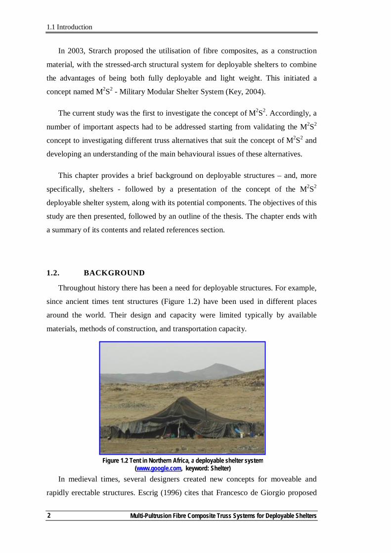
Throughout history there has been a need for deployable structures. For example,
since ancient times tent structures (Figure 1.2) have been used in different places
around the world. Their design and capacity were limited typically by available
materials, methods of construction, and transportation capacity.
In medieval times, several designers created new concepts for moveable and
rapidly erectable structures. Escrig (1996) cites that Francesco de Giorgio proposed
Figure 1.2 Tent in Northern Africa, a deployable shelter system (www.google.com, keyword: Shelter)
1.2 Background
Chapter 1: Introduction
3
machines that could change the geometry of the structures by pulling and pushing,
using diagonal ties. Palladio, Verantius and Primaticio proposed temporary bridge
systems. Leonard da Vinci developed umbrella and pantographic weight-lifting
cranes (Escrig, 1996). In the twentieth century changes in styles of living,
technology, transportation, communication and materials availability have changed
significantly the nature of, and the need for, deployable structures. Modern
deployable structures differ from their predecessors in the fabrication and erection
processes, materials used, and transportation capacity.
Due to their broad scope of applications, different classifications are used for
modern deployable structures. One classification is the environment of application,
where two broad categories are used: earth or space application2 (Chapter 1, p10,
Gantes, 2001). In his review of deployable structures Gantes (2001) summarised the
potential applications of deployable structures on earth as follows:
- emergency shelters or bridges that can be used after earthquakes or other natural disasters;
- temporary buildings in remote construction sites; - shelters for temporary outdoor activities such as road construction,
surveying measurements, or cold weather concreting; - sports facilities;
- relocatable warehouses, hangers and maintenance facilities; - lightweight camping and recreational structures and exhibition structures.
A recurring theme in this list is the provision of shelter systems. The need for
these systems continues to grow for military forces, civilian humanitarian aid, and
natural disaster scenarios.
Light-weight components, wherever possible, are a requirement in deployable
shelters. This is to facilitate deployment and assembly, and to minimise costs
associated with transportation. The assembled elements must be of manageable size
to allow easy manoeuvring and further assembly, without using heavy equipment.
Composite materials have the advantage of higher specific strength and stiffness
compared to other construction materials. In addition, with composite materials, it is
2 By earth we mean structures constructed on our planet, while by space we mean structures placed in orbits in space, for example, foldable telescopes.
1.2 Background
Multi-Pultrusion Fibre Composite Truss Systems for Deployable Shelters
4
possible to engineer the material properties such as strength, chemical attack
resistance, environmental performance and fire resistance, to suite specific
applications. This flexibility provides opportunities as well as challenges to
researchers and engineers who use composites.
1.3. THE CONCEPT OF M2S2
The M2S2 concept is based on the stressed-arch system. However, to improve its
deployability, the M2S2 frames are formed from manageable light-weight elements
that do not require plastic deformation. The top chord deformation is concentrated at
discrete joints designed to facilitate rotation during stress-erection. The M2S2 concept
can be summarised as follows:
- Frames are manufactured, mostly, from identical standard panels with the
dimension of the top chord larger than the bottom chord.
- Standard panels are aligned to form each frame on the ground. Panels are
then connected by the top ‘hinged’ joints. The difference in dimension
between the top chord and the bottom chord allows having initial gaps at the
bottom chord.
- The prestressing cables are threaded through the bottom chord with one side
of the frames fixed to the foundation, while the other is free to move
horizontally.
- Roof sheeting and other services are assembled while the frames are still on
the ground, prior to carrying out any prestressing (Assembly stage, Figure
1.3).
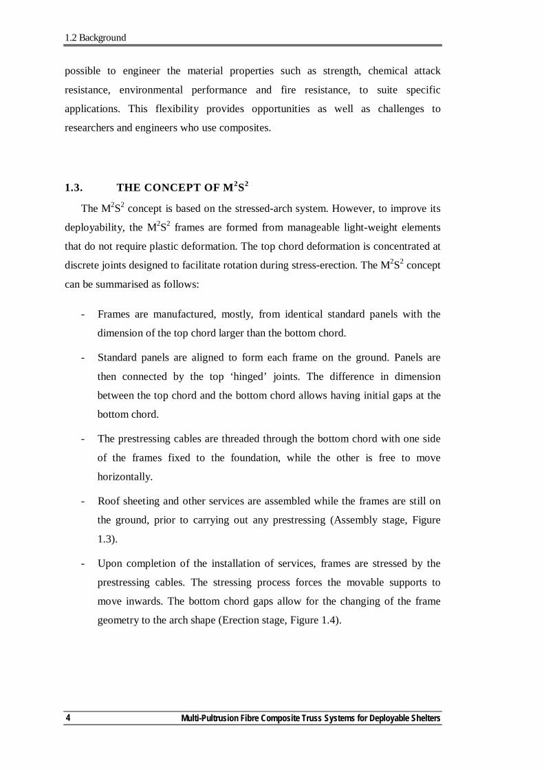
- Upon completion of the installation of services, frames are stressed by the
prestressing cables. The stressing process forces the movable supports to
move inwards. The bottom chord gaps allow for the changing of the frame
geometry to the arch shape (Erection stage, Figure 1.4).
1.3 The Concept of M2S2
Chapter 1: Introduction
5
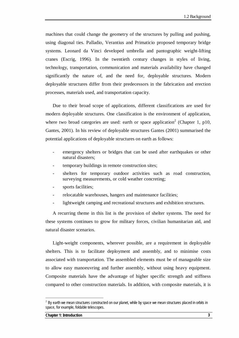
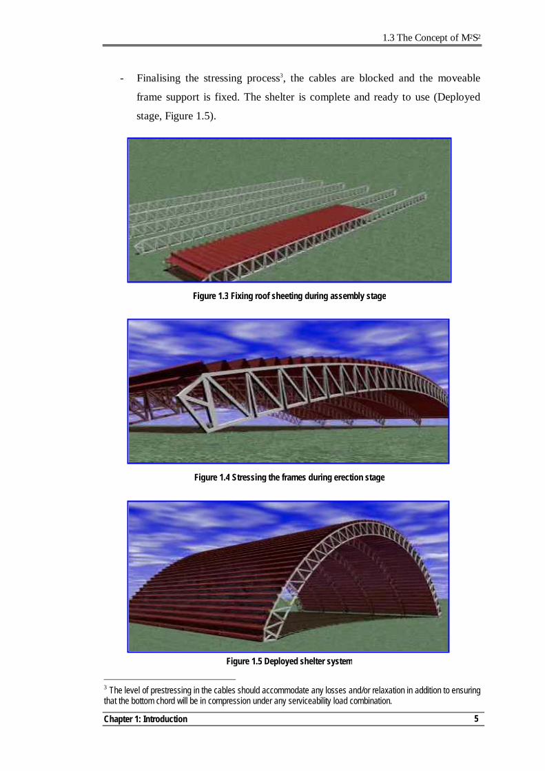
- Finalising the stressing process3, the cables are blocked and the moveable
frame support is fixed. The shelter is complete and ready to use (Deployed
stage, Figure 1.5).
3 The level of prestressing in the cables should accommodate any losses and/or relaxation in addition to ensuring that the bottom chord will be in compression under any serviceability load combination.
Figure 1.4 Stressing the frames during erection stage
Figure 1.5 Deployed shelter system
Figure 1.3 Fixing roof sheeting during assembly stage
1.4 M2S2 – Main Components
Multi-Pultrusion Fibre Composite Truss Systems for Deployable Shelters
6
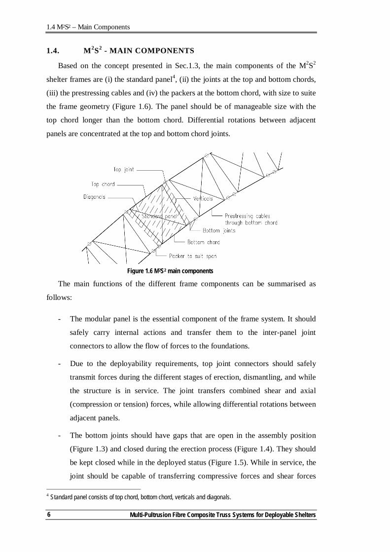
1.4. M2S2 - MAIN COMPONENTS
Based on the concept presented in Sec.1.3, the main components of the M2S2
shelter frames are (i) the standard panel4, (ii) the joints at the top and bottom chords,
(iii) the prestressing cables and (iv) the packers at the bottom chord, with size to suite
the frame geometry (Figure 1.6). The panel should be of manageable size with the
top chord longer than the bottom chord. Differential rotations between adjacent
panels are concentrated at the top and bottom chord joints.
The main functions of the different frame components can be summarised as
follows:
- The modular panel is the essential component of the frame system. It should
safely carry internal actions and transfer them to the inter-panel joint
connectors to allow the flow of forces to the foundations.
- Due to the deployability requirements, top joint connectors should safely
transmit forces during the different stages of erection, dismantling, and while
the structure is in service. The joint transfers combined shear and axial
(compression or tension) forces, while allowing differential rotations between
adjacent panels.
- The bottom joints should have gaps that are open in the assembly position
(Figure 1.3) and closed during the erection process (Figure 1.4). They should
be kept closed while in the deployed status (Figure 1.5). While in service, the
joint should be capable of transferring compressive forces and shear forces 4 Standard panel consists of top chord, bottom chord, verticals and diagonals.
Figure 1.6 M2S2 main components
1.4 M2S2 – Main Components
Chapter 1: Introduction
7
through the joint. In addition, they should accommodate any differential
rotation between connecting panels and packers.
- The prestressing cables have a dual function. They are used as a deploying
mechanism to change the status of the structure from the assembly position
(Figure 1.3) to the deployed position (Figure 1.5) and vice versa. In addition,
they provide the bottom chord with its stiffness, by keeping the bottom chord
in compression under any serviceability limit state.
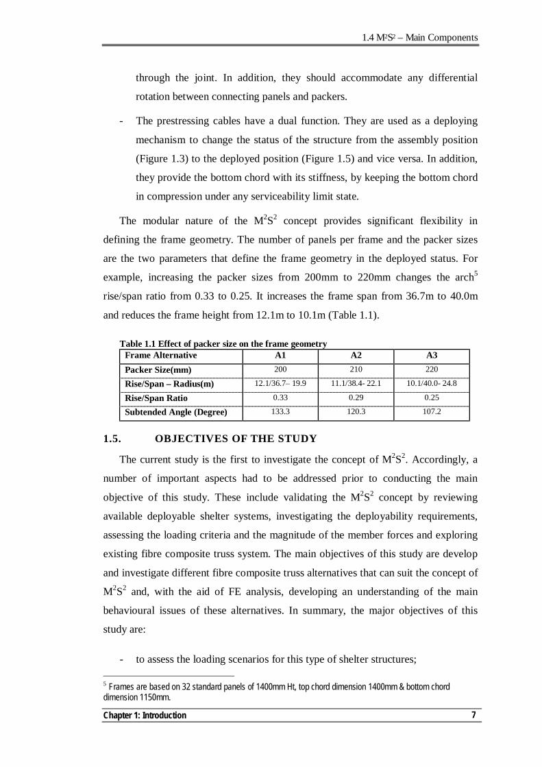
The modular nature of the M2S2 concept provides significant flexibility in
defining the frame geometry. The number of panels per frame and the packer sizes
are the two parameters that define the frame geometry in the deployed status. For
example, increasing the packer sizes from 200mm to 220mm changes the arch5
rise/span ratio from 0.33 to 0.25. It increases the frame span from 36.7m to 40.0m
and reduces the frame height from 12.1m to 10.1m (Table 1.1).
Table 1.1 Effect of packer size on the frame geometry Frame Alternative A1 A2 A3 Packer Size(mm) 200 210 220
Rise/Span – Radius(m) 12.1/36.7– 19.9 11.1/38.4- 22.1 10.1/40.0- 24.8
Rise/Span Ratio 0.33 0.29 0.25
Subtended Angle (Degree) 133.3 120.3 107.2
1.5. OBJECTIVES OF THE STUDY
The current study is the first to investigate the concept of M2S2. Accordingly, a
number of important aspects had to be addressed prior to conducting the main
objective of this study. These include validating the M2S2 concept by reviewing
available deployable shelter systems, investigating the deployability requirements,
assessing the loading criteria and the magnitude of the member forces and exploring
existing fibre composite truss system. The main objectives of this study are develop
and investigate different fibre composite truss alternatives that can suit the concept of
M2S2 and, with the aid of FE analysis, developing an understanding of the main
behavioural issues of these alternatives. In summary, the major objectives of this
study are:
- to assess the loading scenarios for this type of shelter structures; 5 Frames are based on 32 standard panels of 1400mm Ht, top chord dimension 1400mm & bottom chord dimension 1150mm.
1.5 Objectives of the Study
Multi-Pultrusion Fibre Composite Truss Systems for Deployable Shelters
8
- to develop and explore innovative truss systems for the modular panel that mobilises the strengths of composites;
- to develop credible finite element (FE) models;
- to use the tested panels records and the FE analyses results to develop an understanding of the mechanics of force transfers and distributions, potential failure modes and panel capacity;
- to investigate the effect of material distribution and architecture on the panel behaviour;
- to develop a simplified modelling procedure to be used in conducting macro-level analysis for the frame.
It is important to mention that this study is focused on the structural behaviour of
the panel system. Accordingly, no significant material development investigations
are conducted. Existing materials and fibre architectures are used in an efficient form
that suits the structural system. Composites usually face the challenge of being cost-
competitive with other construction materials. No investigations are undertaken in
this study regarding the economical feasibility of the truss system. However,
consideration is given to the complexity of the developed system with the intent of
facilitating efficient manufacturing.
The macro-level FE model is made as simple as possible to represent the
behaviour of the tested panels. The model does not reach the level of detail to model
the constituents of the composite. However, composites are modelled as laminae
with orthotropic material properties with short-term properties.
1.6. OUTLINE OF THE THESIS
Each chapter starts with an overview and ends with a summary of the main
conclusions. Notations used in each chapter are presented at the beginning of the
chapter. Chapter-related references are shown at the end of the chapter. This is in
addition to the Bibliography section at the end of the thesis. Data of detailed nature
are located in appendices at the end of the thesis. As a few prototypes are presented,
a naming convention is used to simplify referencing to these prototypes. A three digit
code is used, proceeded with P, for example P719 is the 7th prototype, revision 1 with
the 9 indicating for reporting.
1.6 Outline of the Thesis
Chapter 1: Introduction
9
Over time, the performance requirements of modern deployable shelters have
become more demanding. This has driven the development of more sophisticated
structural forms and solutions. In Chapter 2, the literature is surveyed for
deployability requirements and different deployable shelter systems developed over
the last forty years. As the truss panel system is the main focus of this investigation,
Chapter 2 also presents a review of the currently available fibre composite truss
systems. The chapter ends with a discussion of the limitations of these systems.
The current investigations started with manufacturing and testing a number of
panel alternatives. Based on these investigations, a range of different panel concepts
were established. These concepts were based on using multi-pultrusion sections for
the chords and verticals, subsequently referred to as the Multi-Pultrusion Truss
System (MPTS). Chapter 3 presents the research work conducted to establish the
first MPTS which had a discrete-diagonal (DD) made of sandwich construction. The
FE method of analysis was used to explore the main behavioural issues including
mechanisms of force transfer, governing failure modes, and panel capacities.
As several of the truss concepts used sandwich structures for the diagonals, the
behaviour of sandwich members under compressive loads was investigated. Chapter
4 starts by surveying the literature for sandwich structure applications and methods
of predicting their capacity. A number of prototype column sets were tested with
different core material layouts. This was to investigate their effect on the column
capacities and failure modes. With the understanding of the behaviour of sandwich
columns, a full-scale truss panel was manufactured and tested with the diagonals in
compression. The chapter concludes with recommendations for sandwich columns,
their capacity predictions, and behavioural discussion of the DD-MPTS with
diagonals subject to compressive forces.
Another alternative of MPTS was achieved by replacing the traditional diagonal
truss member with a complete diaphragm (DI). In Chapter 5, the DI-MPTS
alternative is investigated with three different types of diaphragms. The chapter
concludes with a discussion of the basic behaviour of this new technology.
When developing new innovative composite truss systems, it is important to
provide a simplified modelling approach to predict their behaviour. This can be a
1.6 Outline of the Thesis
Multi-Pultrusion Fibre Composite Truss Systems for Deployable Shelters
10
valuable tool for researchers who are interested in conducting further parametric
studies, without the need to use high-end FE software packages. It is also good for
practising engineers who are interested in using these truss systems to model the
overall behaviour of the truss, as part of the whole structure. Chapter 6 focuses on
these simplified procedures. The developed models are compared with the micro-
analysis model results for the different MPTS. The chapter concludes with general
recommendations for the simplified models.
The main body of the thesis ends with Chapter 7 which contains the main
conclusions and suggestions for future research work. More detailed information is
provided in the attached appendices.
Assessing the loading criteria for deployable structures is a challenging process
that requires engineering judgment, as these structures can be utilised in different
places around the world where different local loading criteria and requirements
apply, as per local national loading codes. A flexible assessment concept for global
loading criteria is presented and discussed in Appendix ‘A’.
The deploying mechanism and the erection stage are integral parts of the
structural behaviour when in service. Two different types of analysis were used to
assess the structural behaviour. Appendix ‘B’ presents and discusses the results of
these different types of analysis.
In Appendix ‘C’, the test results and observations for four different sets of
sandwich columns are presented and briefly discussed.
The concept of DD-MPTS was extended by using double-bay panels. The usage
of these panels can reduce the manufacturing costs due to having fewer panels to
cover the same area. In Appendix ‘D’ both dynamic and static test results of this
panel are presented and discussed.
1.7 Summary
Chapter 1: Introduction
11
1.7. SUMMARY
Deployable shelters are a sub-set of deployable structures that can be used for
military and/or civil applications. The M2S2 deployable shelter system is a further
development of the stressed-arch concept implemented by Strarch using steel frames.
The M2S2 research programme aims to extend the existing Strarch concept into a
system with dramatically improved deployment characteristics. This chapter
presented an overview of the concept and components of the M2S2 shelter system and
outlined the structure of this thesis.
1.8. REFERENCES
Clarke, M. J., and Hancock, G. J. (1994).Behaviour and design of stressed-arch (Strarch) frames. IASS-ASCE International Symposium 1994 on spatial, lattice and tension structures, Atlanta, 200-209.
Escrig, F. (1996). General survey of deployability in architecture. Proceedings of MARAS'96, the second International Conference on Mobile and Rapidly Assembled Structures, Seville, Spain, 3-22.
Gantes, C. J. (2001). Deployable structures: Analysis and design, WIT Press, Southampton, United Kingdom.
Google. Homepage, http://www.google.com. Key, P. W. (2004). The Starch modular military shelter system - Load specification.
Strarch, Sydney. Strarch. Homepage, http://www.strarch.com.
Strarch. (1999). The Strarch building system - Technical discussion. Strarch, Sydney.

Multi-Pultrusion Fibre Composite Truss Systems for Deployable Shelters 12
2.1 General
Chapter 2: Deployable Shelters and Fibre Composite Trusses – State of the Art
13
2. Deployable Shelters and Fibre Composite Trusses -
State of the Art
2.1. GENERAL
The literature review presented in this chapter covers three main areas: (i)
performance criteria for deployable shelters, (ii) available deployable shelter systems
and (iii) structural systems of composite trusses.
Other literature reviews, related to specific topics such as FE modelling
procedures, material characteristics, and buckling behaviour of sandwich members,
are presented in Chapter 3 and Chapter 4 where they are directly related to the topics
discussed in these chapters.
2.2. DEPLOYABLE SHELTERS PERFORMANCE CRITERIA
In searching the literature it was found that military documents, published on
aircraft maintenance hangars, were one of the few sources that provided some
guidance on performance criteria for deployable shelters. Originally, the Required
Operational Capability (ROC), issued by the US Marines Corps (Strarch, 1991),
specified the following criteria:
- no special tools or material handling equipment;
- repairs should be limited to structural and fabrics within the field capability
with no special tools or machines;
- minimum internal dimensions of 27.45mW x 36.6mL x 7.0mH1;
1 W: Width or span, L: Length, H: Height.
2.2 Deployable Shelters Performance Criteria
Multi-Pultrusion Fibre Composite Truss Systems for Deployable Shelters 14
- have an unused service life of 20 years;
- have in-use service life of 15 years with two cycles of assemble and
dismantle per year;
- resistance to deleterious effects of sun, weather, salt and moisture;
- materials used should not support combustion nor produce high levels of
hazardous fumes when exposed to fire;
- designed to withstand service wind speed of 29m/s that gusts to 40m/s;
- able to be erected in wind speed of 9m/s that gusts to 11m/s;
- designed to carry snow loads of 1.0kPa;
- operational temperature of -25c to +55c.
More recently, the Unified Facilities Criteria (UFC) system was introduced with
the purpose of issuing related documents to provide planning, design, construction,
sustainment, restoration, and modernization criteria for the different military
construction projects (Department of Defence, 2005). Due to the light-weight of
deployable shelters, wind loads usually govern the design of these structures. No
specific requirements for deployable shelters are contained in the UFC documents.
Although, they identify important design parameters for aircraft hangars by
specifying the wind load data for different locations in the United States and
worldwide along with specifying the borderline between “open-door” and “closed-
door” shelters, UFC 4-211-01N (Department of Defence, 2004). More detailed
discussion of assessing wind loading on deployable shelters is found in Appendix
‘A’.
2.3. MODERN DEPLOYABLE SHELTERS - REVIEW
The basic components of deployable shelters are the structural system (primary
load transfer) and the cladding system. The cladding system can have different
functions depending on its inherent properties and those of the structural system
used. For example, cladding systems can be used to stabilize the structural system,
assist in carrying primary loads, or can be integrated with the overall load-carrying
system. Consequently the two systems are generally dependent on each other.
2.3 Modern Deployable Shelters - Review
Chapter 2: Deployable Shelters and Fibre Composite Trusses – State of the Art
15
Recent developments of deployable shelter technology can be categorised as:
- Pantograph type structures;
- Air-inflated shelters;
- Rigid frames supporting soft fabric shelters;
This section explains the main characteristics of the different systems.
2.3.1. PANTOGRAPH TYPE STRUCTURES
Various deployable structural forms were explored in the second half of the
twentieth century. Emilio Perez Pinero developed the concept of a travelling theatre
(Peniro, 1961a, 1961b & 1962). His approach was based on the principle of a
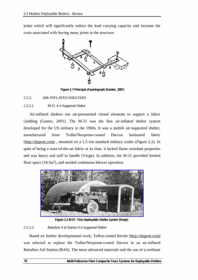
pantograph (Figure 2.1). In this system the frame members have three connections,
with the end ones hinged while the middle one is pivotally connected to the crossing
member. The basic structural system includes rigid bars and wire cables. The
stability of the structure in its erected position is achieved by using locking devices
such as cables. In spite of being a simple concept, using it in a large structure is
problematic as securing and releasing the locking devices require skilled labour and a
temporary supporting system (Chapter 2, Gantes, 2001).
Further development of the pantograph-type deployable structures was carried
out by Zeigler (1976). Zeigler made use of the geometry of a partial spherical dome
that is self-supported in the erected form, without any additional members or cables.
To satisfy the geometrical requirements in Zeigler’s system, each rod must radiate
from the same apical point. This constraint has limited its application. In addition,
the bent nature of the rods in the erected position significantly decreases the load-
carrying capacity of such members (Gantes, 2001). Further investigation of the
behaviour of pantograph systems was carried out by Raskin and Roorda (1996). They
investigated the stiffness and stability of pantographs that utilised additional
boundary conditions in the deployed configuration.
As can be observed, the currently developed pantograph systems have limited
applications associated with the constraints in using them. With fibre composites,
these systems are not favourable due to the nature of stress concentrations at the
2.3 Modern Deployable Shelters - Review
Multi-Pultrusion Fibre Composite Truss Systems for Deployable Shelters 16
joints which will significantly reduce the load carrying capacity and increase the
costs associated with having many joints in the structure.
2.3.2. AIR-INFLATED SHELTERS
2.3.2.1. M-51 Air-Supported Shelter
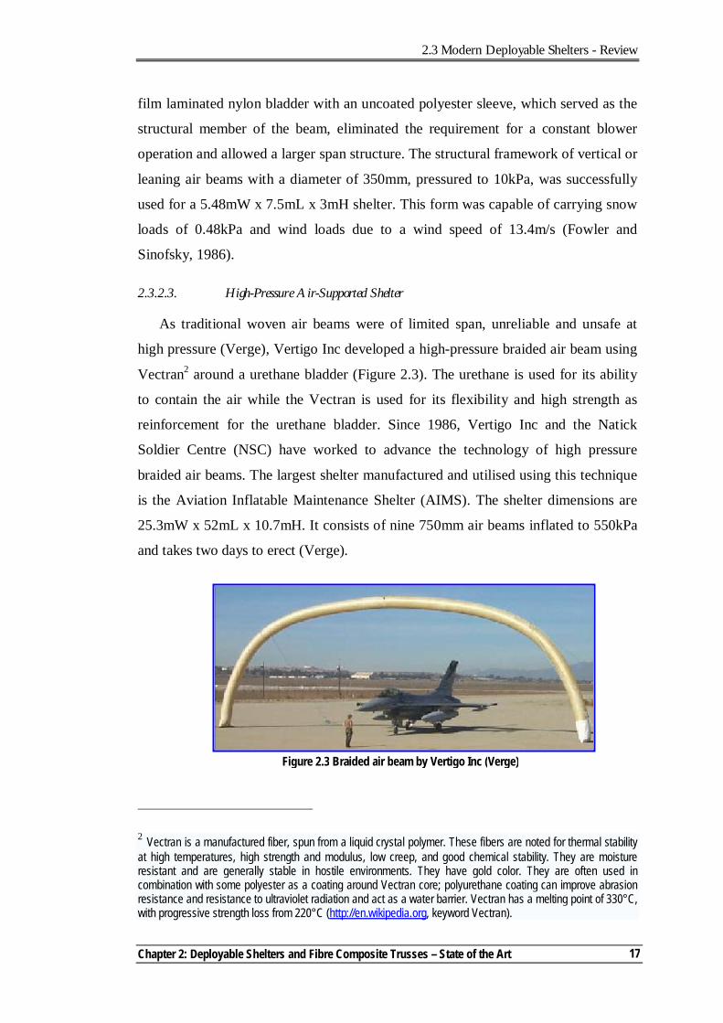
Air-inflated shelters use air-pressurised closed elements to support a fabric
cladding (Gantes, 2001). The M-51 was the first air-inflated shelter system
developed for the US military in the 1960s. It was a mobile air-supported shelter,
manufactured from Tedlar/Neoprene-coated Dacron laminated fabric
(http://dupont.com) , mounted on a 1.5 ton standard military trailer (Figure 2.2). In
spite of being a state-of-the-art fabric at its time, it lacked flame retardant properties
and was heavy and stiff to handle (Verge). In addition, the M-51 provided limited
floor space (18.5m2), and needed continuous blower operation.
2.3.2.2. Battalion Aid Station Air-Supported Shelter
Based on further developmental work, Teflon-coated Kevlar (http://dupont.com)
was selected to replace the Tedlar/Neoprene-coated Dacron in an air-inflated
Battalion Aid Station (BAS). The more advanced materials and the use of a urethane
Figure 2.1 Principal of pantograph (Gantes, 2001)
Figure 2.2 M-51 - First deployable shelter system (Verge)
2.3 Modern Deployable Shelters - Review
Chapter 2: Deployable Shelters and Fibre Composite Trusses – State of the Art
17
film laminated nylon bladder with an uncoated polyester sleeve, which served as the
structural member of the beam, eliminated the requirement for a constant blower
operation and allowed a larger span structure. The structural framework of vertical or
leaning air beams with a diameter of 350mm, pressured to 10kPa, was successfully
used for a 5.48mW x 7.5mL x 3mH shelter. This form was capable of carrying snow
loads of 0.48kPa and wind loads due to a wind speed of 13.4m/s (Fowler and
Sinofsky, 1986).
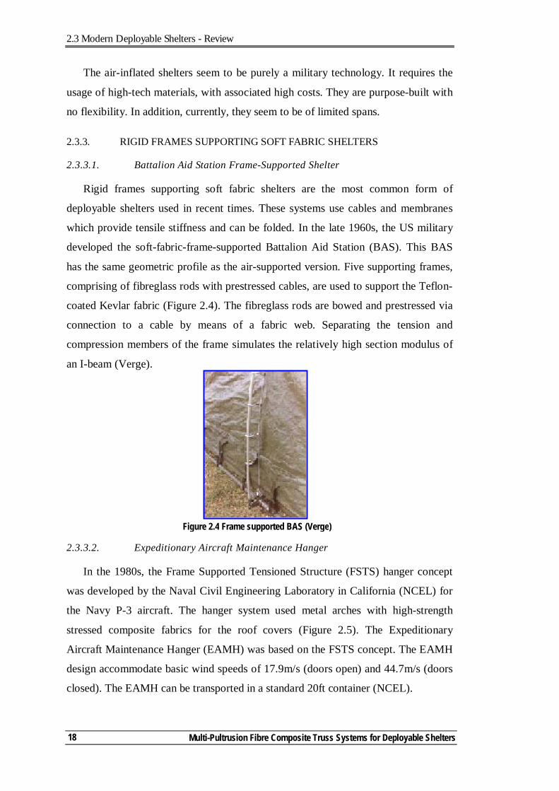
2.3.2.3. High-Pressure Air-Supported Shelter
As traditional woven air beams were of limited span, unreliable and unsafe at
high pressure (Verge), Vertigo Inc developed a high-pressure braided air beam using
Vectran2 around a urethane bladder (Figure 2.3). The urethane is used for its ability
to contain the air while the Vectran is used for its flexibility and high strength as
reinforcement for the urethane bladder. Since 1986, Vertigo Inc and the Natick
Soldier Centre (NSC) have worked to advance the technology of high pressure
braided air beams. The largest shelter manufactured and utilised using this technique
is the Aviation Inflatable Maintenance Shelter (AIMS). The shelter dimensions are
25.3mW x 52mL x 10.7mH. It consists of nine 750mm air beams inflated to 550kPa
and takes two days to erect (Verge).
2 Vectran is a manufactured fiber, spun from a liquid crystal polymer. These fibers are noted for thermal stability at high temperatures, high strength and modulus, low creep, and good chemical stability. They are moisture resistant and are generally stable in hostile environments. They have gold color. They are often used in combination with some polyester as a coating around Vectran core; polyurethane coating can improve abrasion resistance and resistance to ultraviolet radiation and act as a water barrier. Vectran has a melting point of 330°C, with progressive strength loss from 220°C (http://en.wikipedia.org, keyword Vectran).
Figure 2.3 Braided air beam by Vertigo Inc (Verge)
2.3 Modern Deployable Shelters - Review
Multi-Pultrusion Fibre Composite Truss Systems for Deployable Shelters 18
The air-inflated shelters seem to be purely a military technology. It requires the
usage of high-tech materials, with associated high costs. They are purpose-built with
no flexibility. In addition, currently, they seem to be of limited spans.
2.3.3. RIGID FRAMES SUPPORTING SOFT FABRIC SHELTERS
2.3.3.1. Battalion Aid Station Frame-Supported Shelter
Rigid frames supporting soft fabric shelters are the most common form of
deployable shelters used in recent times. These systems use cables and membranes
which provide tensile stiffness and can be folded. In the late 1960s, the US military
developed the soft-fabric-frame-supported Battalion Aid Station (BAS). This BAS
has the same geometric profile as the air-supported version. Five supporting frames,
comprising of fibreglass rods with prestressed cables, are used to support the Teflon-
coated Kevlar fabric (Figure 2.4). The fibreglass rods are bowed and prestressed via
connection to a cable by means of a fabric web. Separating the tension and
compression members of the frame simulates the relatively high section modulus of
an I-beam (Verge).
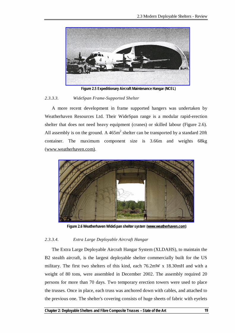
2.3.3.2. Expeditionary Aircraft Maintenance Hanger
In the 1980s, the Frame Supported Tensioned Structure (FSTS) hanger concept
was developed by the Naval Civil Engineering Laboratory in California (NCEL) for
the Navy P-3 aircraft. The hanger system used metal arches with high-strength
stressed composite fabrics for the roof covers (Figure 2.5). The Expeditionary
Aircraft Maintenance Hanger (EAMH) was based on the FSTS concept. The EAMH
design accommodate basic wind speeds of 17.9m/s (doors open) and 44.7m/s (doors
closed). The EAMH can be transported in a standard 20ft container (NCEL).
Figure 2.4 Frame supported BAS (Verge)
2.3 Modern Deployable Shelters - Review
Chapter 2: Deployable Shelters and Fibre Composite Trusses – State of the Art
19
2.3.3.3. WideSpan Frame-Supported Shelter
A more recent development in frame supported hangers was undertaken by
Weatherhaven Resources Ltd. Their WideSpan range is a modular rapid-erection
shelter that does not need heavy equipment (cranes) or skilled labour (Figure 2.6).
All assembly is on the ground. A 465m2 shelter can be transported by a standard 20ft
container. The maximum component size is 3.66m and weights 68kg
(www.weatherhaven.com).
2.3.3.4. Extra Large Deployable Aircraft Hangar
The Extra Large Deployable Aircraft Hangar System (XLDAHS), to maintain the
B2 stealth aircraft, is the largest deployable shelter commercially built for the US
military. The first two shelters of this kind, each 76.2mW x 18.30mH and with a
weight of 80 tons, were assembled in December 2002. The assembly required 20
persons for more than 70 days. Two temporary erection towers were used to place
the trusses. Once in place, each truss was anchored down with cables, and attached to
the previous one. The shelter's covering consists of huge sheets of fabric with eyelets
Figure 2.5 Expeditionary Aircraft Maintenance Hangar (NCEL)
Figure 2.6 Weatherhaven WideSpan shelter system (www.weatherhaven.com)
2.3 Modern Deployable Shelters - Review
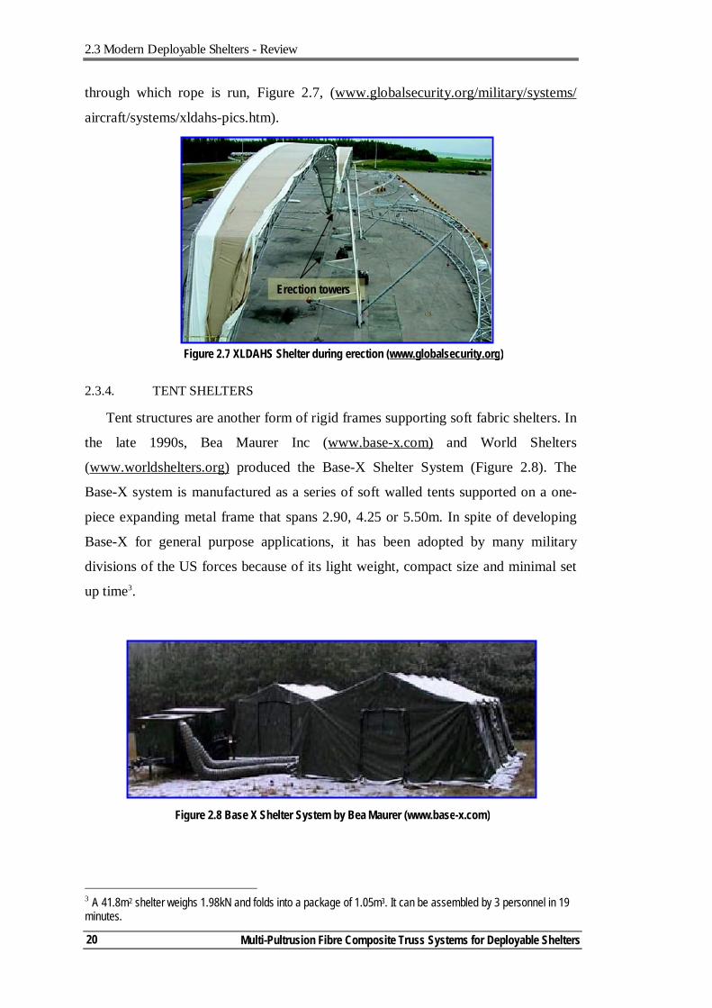
Multi-Pultrusion Fibre Composite Truss Systems for Deployable Shelters 20
through which rope is run, Figure 2.7, (www.globalsecurity.org/military/systems/
aircraft/systems/xldahs-pics.htm).
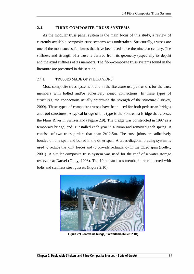
2.3.4. TENT SHELTERS
Tent structures are another form of rigid frames supporting soft fabric shelters. In
the late 1990s, Bea Maurer Inc (www.base-x.com) and World Shelters
(www.worldshelters.org) produced the Base-X Shelter System (Figure 2.8). The
Base-X system is manufactured as a series of soft walled tents supported on a one-
piece expanding metal frame that spans 2.90, 4.25 or 5.50m. In spite of developing
Base-X for general purpose applications, it has been adopted by many military
divisions of the US forces because of its light weight, compact size and minimal set
up time3.
3 A 41.8m2 shelter weighs 1.98kN and folds into a package of 1.05m3. It can be assembled by 3 personnel in 19 minutes.
Figure 2.8 Base X Shelter System by Bea Maurer (www.base-x.com)
Figure 2.7 XLDAHS Shelter during erection (www.globalsecurity.org)
Erection towers
2.4 Fibre Composite Truss Systems
Chapter 2: Deployable Shelters and Fibre Composite Trusses – State of the Art
21
2.4. FIBRE COMPOSITE TRUSS SYSTEMS
As the modular truss panel system is the main focus of this study, a review of
currently available composite truss systems was undertaken. Structurally, trusses are
one of the most successful forms that have been used since the nineteen century. The
stiffness and strength of a truss is derived from its geometry (especially its depth)
and the axial stiffness of its members. The fibre-composite truss systems found in the
literature are presented in this section.
2.4.1. TRUSSES MADE OF PULTRUSIONS
Most composite truss systems found in the literature use pultrusions for the truss
members with bolted and/or adhesively joined connections. In these types of
structures, the connections usually determine the strength of the structure (Turvey,
2000). These types of composite trusses have been used for both pedestrian bridges
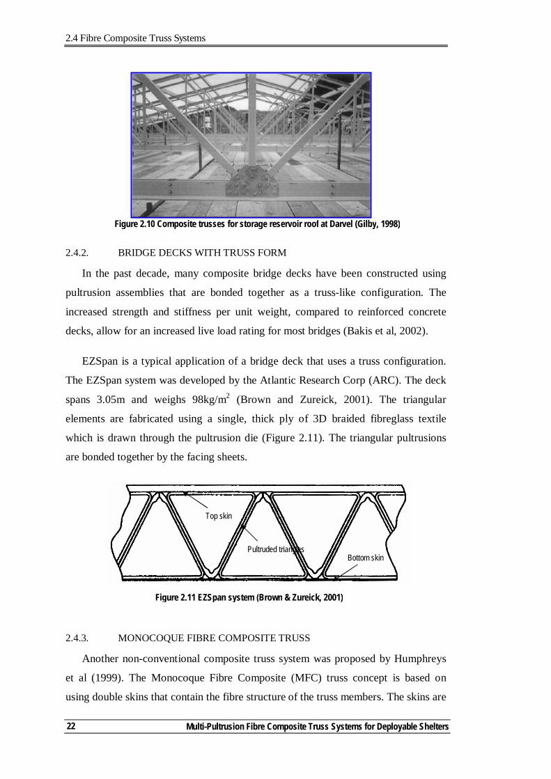
and roof structures. A typical bridge of this type is the Pontresina Bridge that crosses
the Flanz River in Switzerland (Figure 2.9). The bridge was constructed in 1997 as a
temporary bridge, and is installed each year in autumn and removed each spring. It
consists of two truss girders that span 2x12.5m. The truss joints are adhesively
bonded on one span and bolted in the other span. A cross-diagonal bracing system is
used to reduce the joint forces and to provide redundancy in the glued span (Keller,
2001). A similar composite truss system was used for the roof of a water storage
reservoir at Darvel (Gilby, 1998). The 19m span truss members are connected with
bolts and stainless steel gussets (Figure 2.10).
Figure 2.9 Pontresina bridge, Switzerland (Keller, 2001)
2.4 Fibre Composite Truss Systems
Multi-Pultrusion Fibre Composite Truss Systems for Deployable Shelters 22
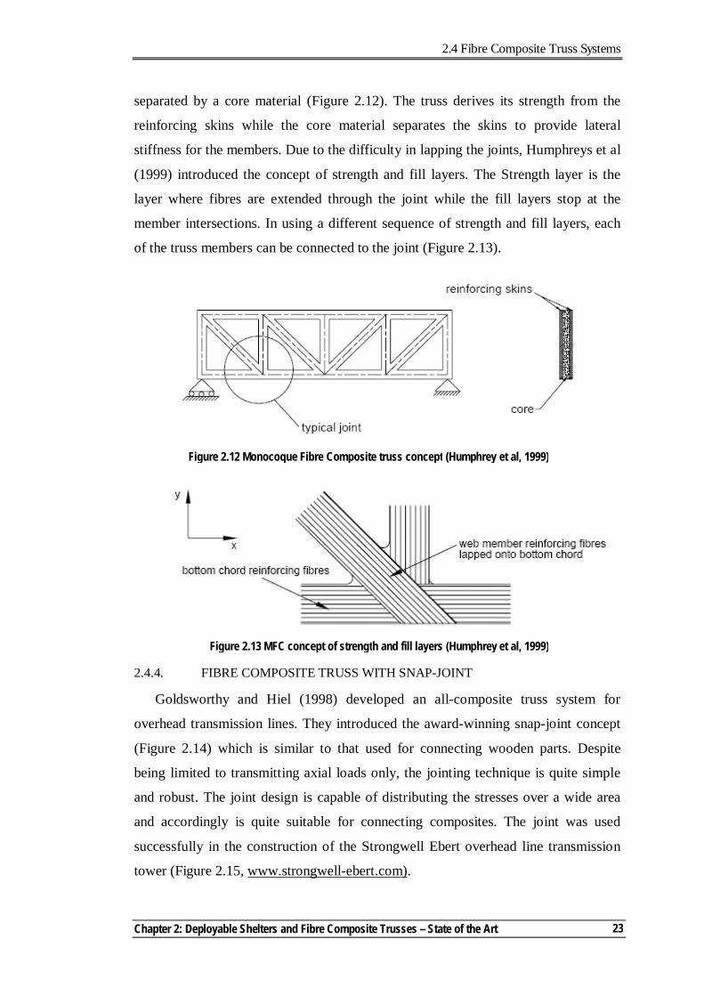
2.4.2. BRIDGE DECKS WITH TRUSS FORM
In the past decade, many composite bridge decks have been constructed using
pultrusion assemblies that are bonded together as a truss-like configuration. The
increased strength and stiffness per unit weight, compared to reinforced concrete
decks, allow for an increased live load rating for most bridges (Bakis et al, 2002).
EZSpan is a typical application of a bridge deck that uses a truss configuration.
The EZSpan system was developed by the Atlantic Research Corp (ARC). The deck
spans 3.05m and weighs 98kg/m2 (Brown and Zureick, 2001). The triangular
elements are fabricated using a single, thick ply of 3D braided fibreglass textile
which is drawn through the pultrusion die (Figure 2.11). The triangular pultrusions
are bonded together by the facing sheets.
2.4.3. MONOCOQUE FIBRE COMPOSITE TRUSS
Another non-conventional composite truss system was proposed by Humphreys
et al (1999). The Monocoque Fibre Composite (MFC) truss concept is based on
using double skins that contain the fibre structure of the truss members. The skins are
Figure 2.10 Composite trusses for storage reservoir roof at Darvel (Gilby, 1998)
Figure 2.11 EZSpan system (Brown & Zureick, 2001)
Top skin
Bottom skin Pultruded triangles
2.4 Fibre Composite Truss Systems
Chapter 2: Deployable Shelters and Fibre Composite Trusses – State of the Art
23
separated by a core material (Figure 2.12). The truss derives its strength from the
reinforcing skins while the core material separates the skins to provide lateral
stiffness for the members. Due to the difficulty in lapping the joints, Humphreys et al
(1999) introduced the concept of strength and fill layers. The Strength layer is the
layer where fibres are extended through the joint while the fill layers stop at the
member intersections. In using a different sequence of strength and fill layers, each
of the truss members can be connected to the joint (Figure 2.13).
2.4.4. FIBRE COMPOSITE TRUSS WITH SNAP-JOINT
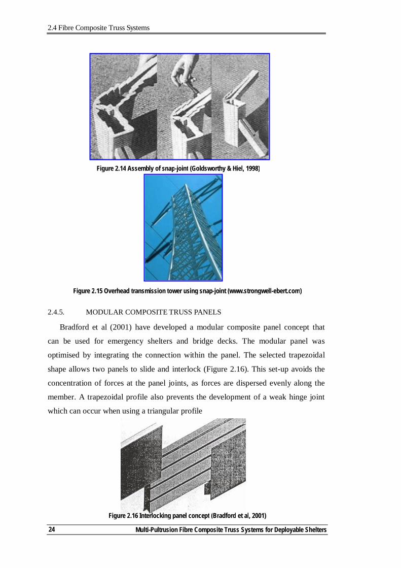
Goldsworthy and Hiel (1998) developed an all-composite truss system for
overhead transmission lines. They introduced the award-winning snap-joint concept
(Figure 2.14) which is similar to that used for connecting wooden parts. Despite
being limited to transmitting axial loads only, the jointing technique is quite simple
and robust. The joint design is capable of distributing the stresses over a wide area
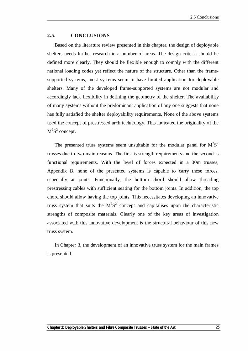
and accordingly is quite suitable for connecting composites. The joint was used
successfully in the construction of the Strongwell Ebert overhead line transmission
tower (Figure 2.15, www.strongwell-ebert.com).
Figure 2.12 Monocoque Fibre Composite truss concept (Humphrey et al, 1999)
Figure 2.13 MFC concept of strength and fill layers (Humphrey et al, 1999)
2.4 Fibre Composite Truss Systems
Multi-Pultrusion Fibre Composite Truss Systems for Deployable Shelters 24
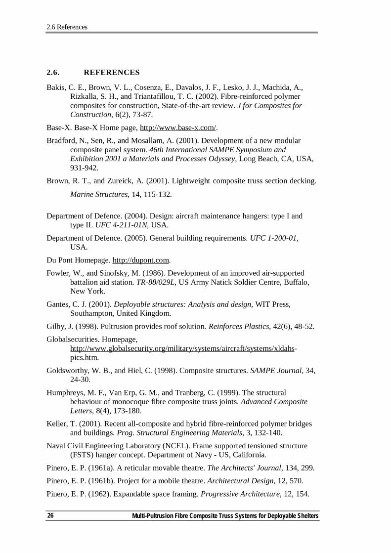
2.4.5. MODULAR COMPOSITE TRUSS PANELS
Bradford et al (2001) have developed a modular composite panel concept that
can be used for emergency shelters and bridge decks. The modular panel was
optimised by integrating the connection within the panel. The selected trapezoidal
shape allows two panels to slide and interlock (Figure 2.16). This set-up avoids the
concentration of forces at the panel joints, as forces are dispersed evenly along the
member. A trapezoidal profile also prevents the development of a weak hinge joint
which can occur when using a triangular profile
Figure 2.14 Assembly of snap-joint (Goldsworthy & Hiel, 1998)
Figure 2.15 Overhead transmission tower using snap-joint (www.strongwell-ebert.com)
Figure 2.16 Interlocking panel concept (Bradford et al, 2001)
2.5 Conclusions
Chapter 2: Deployable Shelters and Fibre Composite Trusses – State of the Art
25
2.5. CONCLUSIONS
Based on the literature review presented in this chapter, the design of deployable
shelters needs further research in a number of areas. The design criteria should be
defined more clearly. They should be flexible enough to comply with the different
national loading codes yet reflect the nature of the structure. Other than the frame-
supported systems, most systems seem to have limited application for deployable
shelters. Many of the developed frame-supported systems are not modular and
accordingly lack flexibility in defining the geometry of the shelter. The availability
of many systems without the predominant application of any one suggests that none
has fully satisfied the shelter deployability requirements. None of the above systems
used the concept of prestressed arch technology. This indicated the originality of the
M2S2 concept.
The presented truss systems seem unsuitable for the modular panel for M2S2
trusses due to two main reasons. The first is strength requirements and the second is
functional requirements. With the level of forces expected in a 30m trusses,
Appendix B, none of the presented systems is capable to carry these forces,
especially at joints. Functionally, the bottom chord should allow threading
prestressing cables with sufficient seating for the bottom joints. In addition, the top
chord should allow having the top joints. This necessitates developing an innovative
truss system that suits the M2S2 concept and capitalises upon the characteristic
strengths of composite materials. Clearly one of the key areas of investigation
associated with this innovative development is the structural behaviour of this new
truss system.
In Chapter 3, the development of an innovative truss system for the main frames
is presented.
2.6 References
Multi-Pultrusion Fibre Composite Truss Systems for Deployable Shelters 26
2.6. REFERENCES
Bakis, C. E., Brown, V. L., Cosenza, E., Davalos, J. F., Lesko, J. J., Machida, A., Rizkalla, S. H., and Triantafillou, T. C. (2002). Fibre-reinforced polymer composites for construction, State-of-the-art review. J for Composites for Construction, 6(2), 73-87.
Base-X. Base-X Home page, http://www.base-x.com/. Bradford, N., Sen, R., and Mosallam, A. (2001). Development of a new modular
composite panel system. 46th International SAMPE Symposium and Exhibition 2001 a Materials and Processes Odyssey, Long Beach, CA, USA, 931-942.
Brown, R. T., and Zureick, A. (2001). Lightweight composite truss section decking.
Marine Structures, 14, 115-132.
Department of Defence. (2004). Design: aircraft maintenance hangers: type I and type II. UFC 4-211-01N, USA.
Department of Defence. (2005). General building requirements. UFC 1-200-01, USA.
Du Pont Homepage. http://dupont.com. Fowler, W., and Sinofsky, M. (1986). Development of an improved air-supported
battalion aid station. TR-88/029L, US Army Natick Soldier Centre, Buffalo, New York.
Gantes, C. J. (2001). Deployable structures: Analysis and design, WIT Press, Southampton, United Kingdom.
Gilby, J. (1998). Pultrusion provides roof solution. Reinforces Plastics, 42(6), 48-52. Globalsecurities. Homepage,
http://www.globalsecurity.org/military/systems/aircraft/systems/xldahs-pics.htm.
Goldsworthy, W. B., and Hiel, C. (1998). Composite structures. SAMPE Journal, 34, 24-30.
Humphreys, M. F., Van Erp, G. M., and Tranberg, C. (1999). The structural behaviour of monocoque fibre composite truss joints. Advanced Composite Letters, 8(4), 173-180.
Keller, T. (2001). Recent all-composite and hybrid fibre-reinforced polymer bridges and buildings. Prog. Structural Engineering Materials, 3, 132-140.
Naval Civil Engineering Laboratory (NCEL). Frame supported tensioned structure (FSTS) hanger concept. Department of Navy - US, California.
Pinero, E. P. (1961a). A reticular movable theatre. The Architects' Journal, 134, 299. Pinero, E. P. (1961b). Project for a mobile theatre. Architectural Design, 12, 570.
Pinero, E. P. (1962). Expandable space framing. Progressive Architecture, 12, 154.
2.6 References
Chapter 2: Deployable Shelters and Fibre Composite Trusses – State of the Art
27
Raskin, I., and Roorda, J. (1996). Buckling force for deployable pantographic columns. Proceedings of MARAS'96, the second International Conference on Mobile and Rapidly Assembled Structures, Seville, Spain, 305-314.
Strarch. (1991). An analysis of US military requirements for large deployable shelters. Strarch, Sydney.
Strongwell. Strongwell Ebert LLC Home page, http://strongwell-ebert.com/.
Turvey, G. J. (2000). Bolted connections in PFRP structures. Prog. Structural Engineering Materials, 2, 146-156.
Verge, A. S. Rapidly deployable structures in collective protection systems. U.S. Army Natick Soldier Center (www.natick.army.mil), Massachusetts, USA.
Weatherhaven. Homepage, http://www.weatherhaven.com/. Wikipedia home page. http://en.wikipedia.org.
World Shelters. Homepage, http://www.worldshelters.com. Zeigler, T. R. (1976). Collapsible self-supporting structures. US Pat 3 968 808, USA.

Chapter 3 Notations
Multi-Pultrusion Fibre Composite Truss Systems for Deployable Shelters
28
Chapter 3 Notations
b Pultrusion flange flat clear width
Djj Shell section jj stiffness matrix parameter
E1 Tensile modulus in the 1-1 (fibre) direction
E2 Tensile modulus in the 2-2 (normal to fibre) direction
E3 Tensile modulus in the 3-3 (normal to laminate plane) direction
G12 Shear modulus in the 1-2 plane
Gkl Shear modulus in the k-l plane
Kii Thick shell transverse shear stiffness in the i-i direction
l Plate characteristic length
t Pultrusion flange thickness
λ Plate slenderness
νmn Poisson’s ratio of the m-n plane
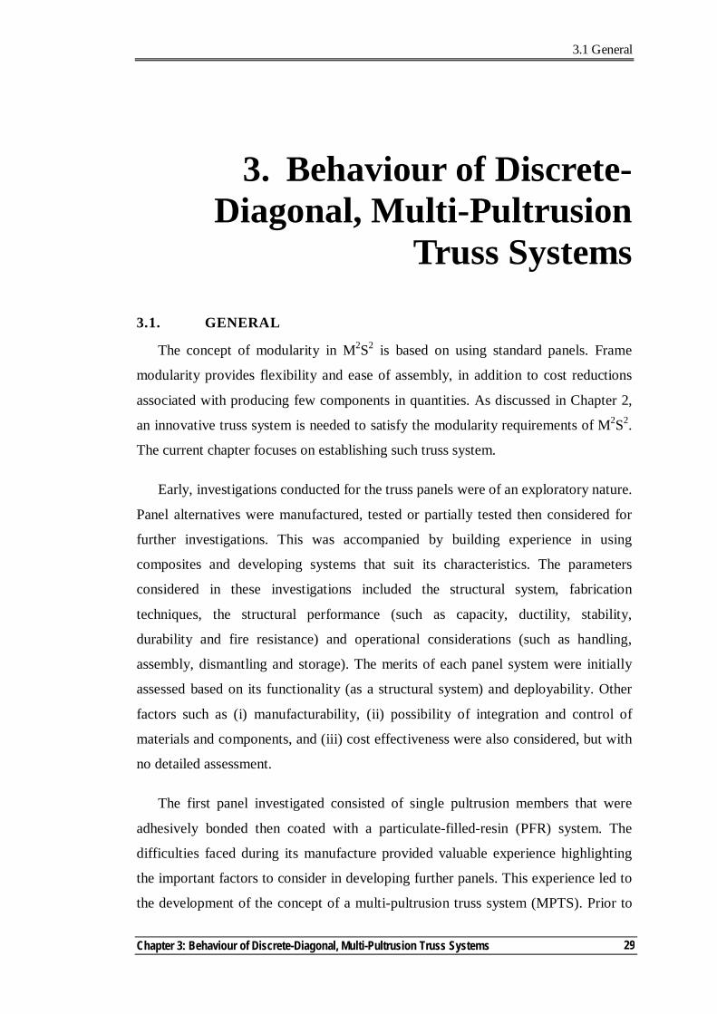
3.1 General
Chapter 3: Behaviour of Discrete-Diagonal, Multi-Pultrusion Truss Systems
29
3. Behaviour of Discrete-Diagonal, Multi-Pultrusion
Truss Systems
3.1. GENERAL
The concept of modularity in M2S2 is based on using standard panels. Frame
modularity provides flexibility and ease of assembly, in addition to cost reductions
associated with producing few components in quantities. As discussed in Chapter 2,
an innovative truss system is needed to satisfy the modularity requirements of M2S2.
The current chapter focuses on establishing such truss system.
Early, investigations conducted for the truss panels were of an exploratory nature.
Panel alternatives were manufactured, tested or partially tested then considered for
further investigations. This was accompanied by building experience in using
composites and developing systems that suit its characteristics. The parameters
considered in these investigations included the structural system, fabrication
techniques, the structural performance (such as capacity, ductility, stability,
durability and fire resistance) and operational considerations (such as handling,
assembly, dismantling and storage). The merits of each panel system were initially
assessed based on its functionality (as a structural system) and deployability. Other
factors such as (i) manufacturability, (ii) possibility of integration and control of
materials and components, and (iii) cost effectiveness were also considered, but with
no detailed assessment.
The first panel investigated consisted of single pultrusion members that were
adhesively bonded then coated with a particulate-filled-resin (PFR) system. The
difficulties faced during its manufacture provided valuable experience highlighting
the important factors to consider in developing further panels. This experience led to
the development of the concept of a multi-pultrusion truss system (MPTS). Prior to
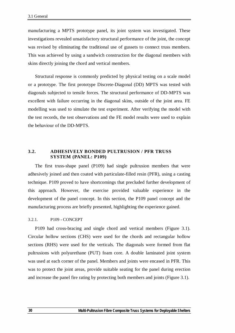
3.1 General
Multi-Pultrusion Fibre Composite Truss Systems for Deployable Shelters
30
manufacturing a MPTS prototype panel, its joint system was investigated. These
investigations revealed unsatisfactory structural performance of the joint, the concept
was revised by eliminating the traditional use of gussets to connect truss members.
This was achieved by using a sandwich construction for the diagonal members with
skins directly joining the chord and vertical members.
Structural response is commonly predicted by physical testing on a scale model
or a prototype. The first prototype Discrete-Diagonal (DD) MPTS was tested with
diagonals subjected to tensile forces. The structural performance of DD-MPTS was
excellent with failure occurring in the diagonal skins, outside of the joint area. FE
modelling was used to simulate the test experiment. After verifying the model with
the test records, the test observations and the FE model results were used to explain
the behaviour of the DD-MPTS.
3.2. ADHESIVELY BONDED PULTRUSION / PFR TRUSS SYSTEM (PANEL: P109)
The first truss-shape panel (P109) had single pultrusion members that were
adhesively joined and then coated with particulate-filled resin (PFR), using a casting
technique. P109 proved to have shortcomings that precluded further development of
this approach. However, the exercise provided valuable experience in the
development of the panel concept. In this section, the P109 panel concept and the
manufacturing process are briefly presented, highlighting the experience gained.
3.2.1. P109 - CONCEPT
P109 had cross-bracing and single chord and vertical members (Figure 3.1).
Circular hollow sections (CHS) were used for the chords and rectangular hollow
sections (RHS) were used for the verticals. The diagonals were formed from flat
pultrusions with polyurethane (PUT) foam core. A double laminated joint system
was used at each corner of the panel. Members and joints were encased in PFR. This
was to protect the joint areas, provide suitable seating for the panel during erection
and increase the panel fire rating by protecting both members and joints (Figure 3.1).
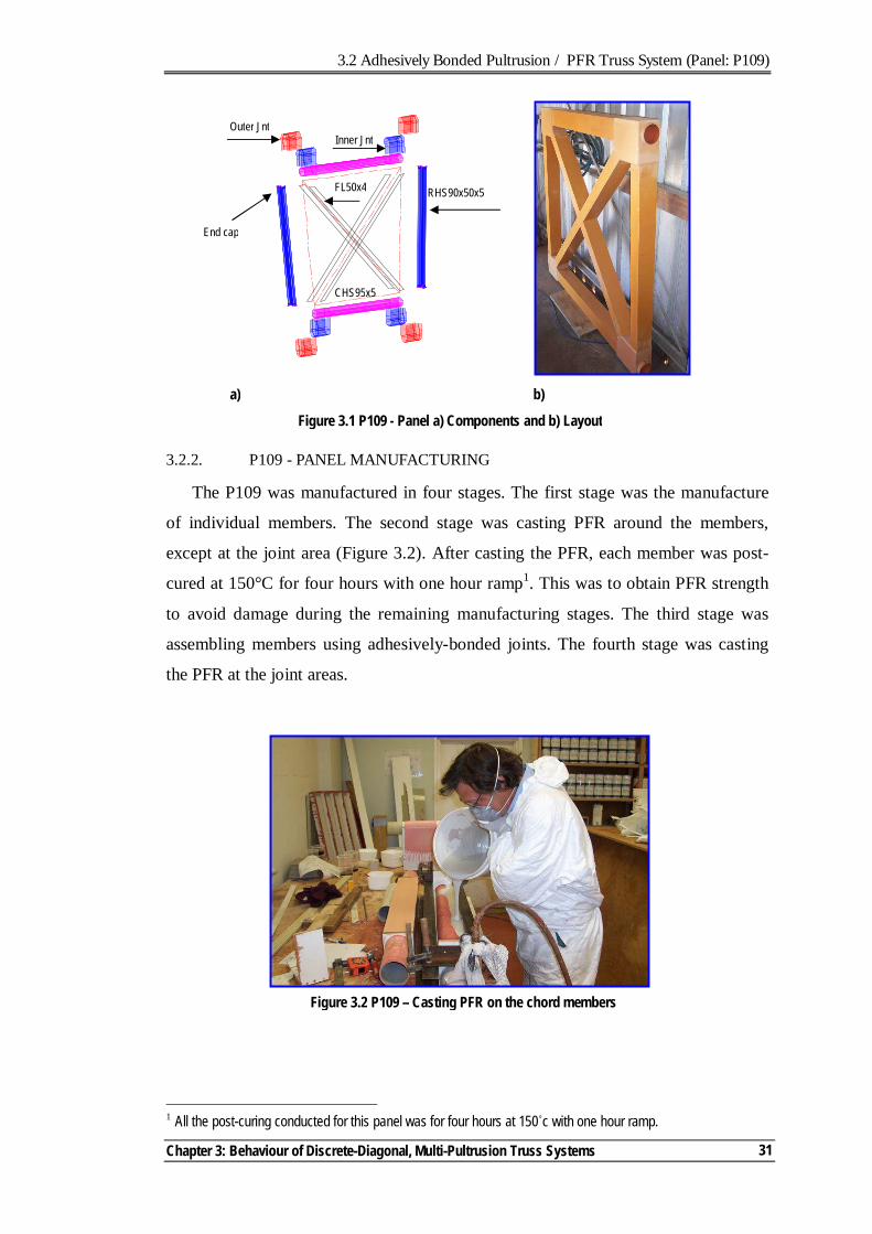
3.2 Adhesively Bonded Pultrusion / PFR Truss System (Panel: P109)
Chapter 3: Behaviour of Discrete-Diagonal, Multi-Pultrusion Truss Systems
31
3.2.2. P109 - PANEL MANUFACTURING
The P109 was manufactured in four stages. The first stage was the manufacture
of individual members. The second stage was casting PFR around the members,
except at the joint area (Figure 3.2). After casting the PFR, each member was post-
cured at 150°C for four hours with one hour ramp1. This was to obtain PFR strength
to avoid damage during the remaining manufacturing stages. The third stage was
assembling members using adhesively-bonded joints. The fourth stage was casting
the PFR at the joint areas.
1 All the post-curing conducted for this panel was for four hours at 150˚c with one hour ramp.
Figure 3.2 P109 – Casting PFR on the chord members
Figure 3.1 P109 - Panel a) Components and b) Layout
Outer Jnt
FL50x4 RHS90x50x5
CHS95x5
End cap
Inner Jnt
a) b)
3.2 Adhesively Bonded Pultrusion / PFR Truss System (Panel: P109)
Multi-Pultrusion Fibre Composite Truss Systems for Deployable Shelters
32
3.2.3. P109 - PANEL EVALUATION
P109 was the first structure, in composites, to be built by the author. This
exercise provided good experience in dealing with different and difficult materials at
different stages of their forms (fibres, resins, adhesive and PFR), in curing and post-
curing, and in manufacturing techniques. However, the P109 panel system suffered
from serious shortcomings, summarised below, that prompted reassessment of its
development.
- The manufacturing and assembling procedures were complex and labour
intensive. This was due to using components of non-standard sizes, having
many components, using curved-shaped surfaces and the multi-procedure
process.
- Using CHSs for the chords resulted in continuous joints in double layers.
This can be good in transferring forces from the diagonal flats to the joint
layers. However, using curved surfaces complicated the assembly with other
components.
- The quality of the joint gluing was very difficult to monitor and therefore
ensure. This raised a concern about the level of quality control required in a
normal manufacturing environment.
- The curing sequence and the use of PFR with variable thicknesses resulted
in cracks forming in many locations in the PFR. These cracks were not of
structural significance but were expected to affect the functionality of the
PFR.
- Despite using light-weight fillers for the PFR, the PFR contributed about
60% of the panel weight with minor contribution to the panel strength.
3.2.4. IMPORTANT PARAMETERS FOR THE PANEL SYSTEM
The experience gained from manufacturing P109 contributed to the identification
of a number of important factors that need to be considered in the next version of the
panel system. These are:
- Flat sided components. This is important in the manufacturing and assembly
processes. Flat side components, generally, do not require special tooling to
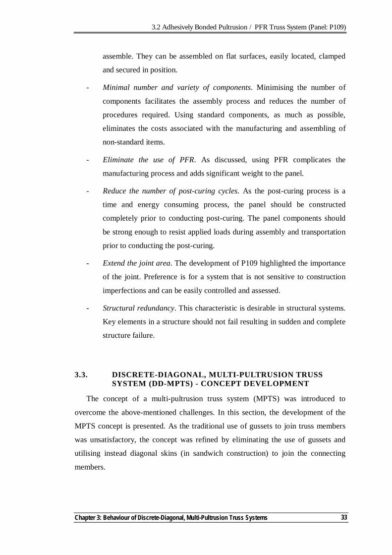
3.2 Adhesively Bonded Pultrusion / PFR Truss System (Panel: P109)
Chapter 3: Behaviour of Discrete-Diagonal, Multi-Pultrusion Truss Systems
33
assemble. They can be assembled on flat surfaces, easily located, clamped
and secured in position.
- Minimal number and variety of components. Minimising the number of
components facilitates the assembly process and reduces the number of
procedures required. Using standard components, as much as possible,
eliminates the costs associated with the manufacturing and assembling of
non-standard items.
- Eliminate the use of PFR. As discussed, using PFR complicates the
manufacturing process and adds significant weight to the panel.
- Reduce the number of post-curing cycles. As the post-curing process is a
time and energy consuming process, the panel should be constructed
completely prior to conducting post-curing. The panel components should
be strong enough to resist applied loads during assembly and transportation
prior to conducting the post-curing.
- Extend the joint area. The development of P109 highlighted the importance
of the joint. Preference is for a system that is not sensitive to construction
imperfections and can be easily controlled and assessed.
- Structural redundancy. This characteristic is desirable in structural systems.
Key elements in a structure should not fail resulting in sudden and complete
structure failure.
3.3. DISCRETE-DIAGONAL, MULTI-PULTRUSION TRUSS SYSTEM (DD-MPTS) - CONCEPT DEVELOPMENT
The concept of a multi-pultrusion truss system (MPTS) was introduced to
overcome the above-mentioned challenges. In this section, the development of the
MPTS concept is presented. As the traditional use of gussets to join truss members
was unsatisfactory, the concept was refined by eliminating the use of gussets and
utilising instead diagonal skins (in sandwich construction) to join the connecting
members.
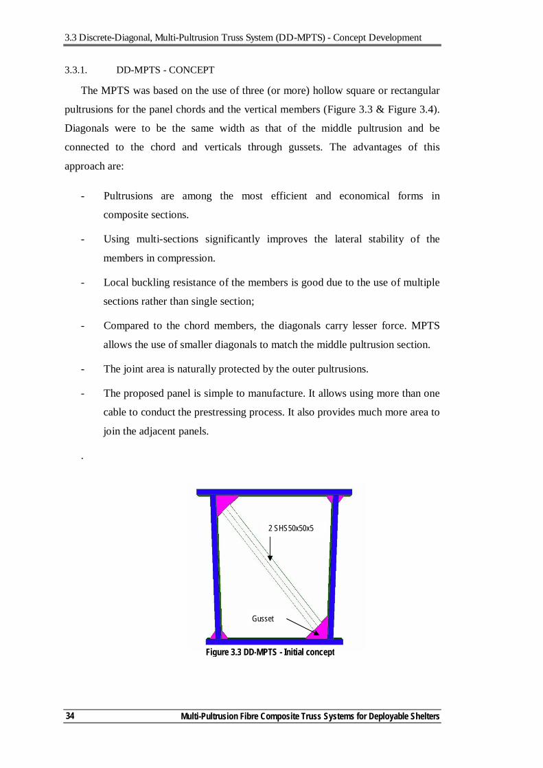
3.3 Discrete-Diagonal, Multi-Pultrusion Truss System (DD-MPTS) - Concept Development
Multi-Pultrusion Fibre Composite Truss Systems for Deployable Shelters
34
3.3.1. DD-MPTS - CONCEPT
The MPTS was based on the use of three (or more) hollow square or rectangular
pultrusions for the panel chords and the vertical members (Figure 3.3 & Figure 3.4).
Diagonals were to be the same width as that of the middle pultrusion and be
connected to the chord and verticals through gussets. The advantages of this
approach are:
- Pultrusions are among the most efficient and economical forms in
composite sections.
- Using multi-sections significantly improves the lateral stability of the
members in compression.
- Local buckling resistance of the members is good due to the use of multiple
sections rather than single section;
- Compared to the chord members, the diagonals carry lesser force. MPTS
allows the use of smaller diagonals to match the middle pultrusion section.
- The joint area is naturally protected by the outer pultrusions.
- The proposed panel is simple to manufacture. It allows using more than one
cable to conduct the prestressing process. It also provides much more area to
join the adjacent panels.
.
2 SHS50x50x5
Gusset
Figure 3.3 DD-MPTS - Initial concept
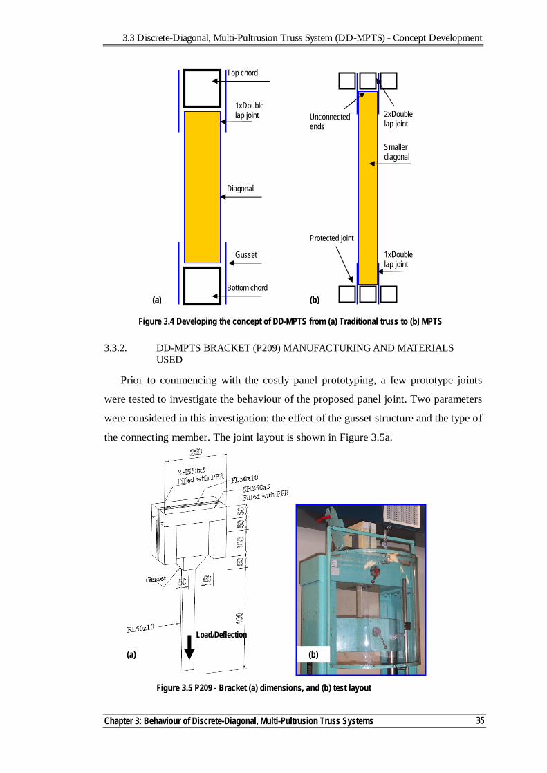
3.3 Discrete-Diagonal, Multi-Pultrusion Truss System (DD-MPTS) - Concept Development
Chapter 3: Behaviour of Discrete-Diagonal, Multi-Pultrusion Truss Systems
35
3.3.2. DD-MPTS BRACKET (P209) MANUFACTURING AND MATERIALS USED
Prior to commencing with the costly panel prototyping, a few prototype joints
were tested to investigate the behaviour of the proposed panel joint. Two parameters
were considered in this investigation: the effect of the gusset structure and the type of
the connecting member. The joint layout is shown in Figure 3.5a.
Diagonal
Gusset
Bottom chord
Top chord
1xDouble lap joint
1xDouble lap joint
2xDouble lap joint
Smaller diagonal
Protected joint
Unconnected ends
Figure 3.4 Developing the concept of DD-MPTS from (a) Traditional truss to (b) MPTS
(a) (b)
Load/Deflection
Figure 3.5 P209 - Bracket (a) dimensions, and (b) test layout
(a) (b)
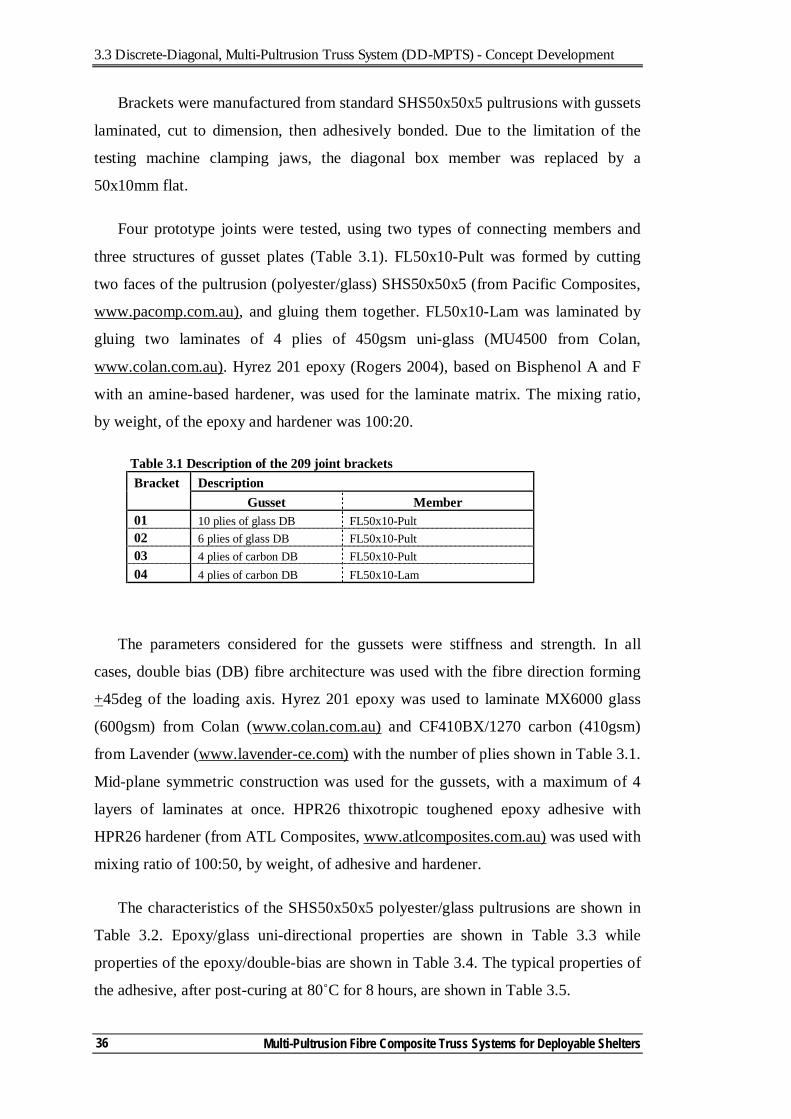
3.3 Discrete-Diagonal, Multi-Pultrusion Truss System (DD-MPTS) - Concept Development
Multi-Pultrusion Fibre Composite Truss Systems for Deployable Shelters
36
Brackets were manufactured from standard SHS50x50x5 pultrusions with gussets
laminated, cut to dimension, then adhesively bonded. Due to the limitation of the
testing machine clamping jaws, the diagonal box member was replaced by a
50x10mm flat.
Four prototype joints were tested, using two types of connecting members and
three structures of gusset plates (Table 3.1). FL50x10-Pult was formed by cutting
two faces of the pultrusion (polyester/glass) SHS50x50x5 (from Pacific Composites,
www.pacomp.com.au), and gluing them together. FL50x10-Lam was laminated by
gluing two laminates of 4 plies of 450gsm uni-glass (MU4500 from Colan,
www.colan.com.au). Hyrez 201 epoxy (Rogers 2004), based on Bisphenol A and F
with an amine-based hardener, was used for the laminate matrix. The mixing ratio,
by weight, of the epoxy and hardener was 100:20.
Table 3.1 Description of the 209 joint brackets Bracket Description Gusset Member 01 10 plies of glass DB FL50x10-Pult 02 6 plies of glass DB FL50x10-Pult 03 4 plies of carbon DB FL50x10-Pult 04 4 plies of carbon DB FL50x10-Lam
The parameters considered for the gussets were stiffness and strength. In all
cases, double bias (DB) fibre architecture was used with the fibre direction forming
+45deg of the loading axis. Hyrez 201 epoxy was used to laminate MX6000 glass
(600gsm) from Colan (www.colan.com.au) and CF410BX/1270 carbon (410gsm)
from Lavender (www.lavender-ce.com) with the number of plies shown in Table 3.1.
Mid-plane symmetric construction was used for the gussets, with a maximum of 4
layers of laminates at once. HPR26 thixotropic toughened epoxy adhesive with
HPR26 hardener (from ATL Composites, www.atlcomposites.com.au) was used with
mixing ratio of 100:50, by weight, of adhesive and hardener.
The characteristics of the SHS50x50x5 polyester/glass pultrusions are shown in
Table 3.2. Epoxy/glass uni-directional properties are shown in Table 3.3 while
properties of the epoxy/double-bias are shown in Table 3.4. The typical properties of
the adhesive, after post-curing at 80˚C for 8 hours, are shown in Table 3.5.
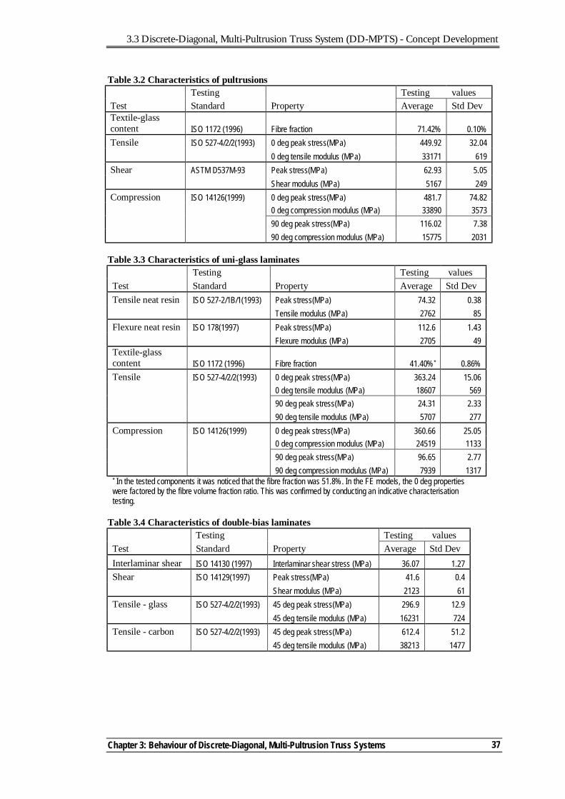
3.3 Discrete-Diagonal, Multi-Pultrusion Truss System (DD-MPTS) - Concept Development
Chapter 3: Behaviour of Discrete-Diagonal, Multi-Pultrusion Truss Systems
37
Table 3.2 Characteristics of pultrusions Testing Testing values Test Standard Property Average Std Dev Textile-glass content ISO 1172 (1996) Fibre fraction 71.42% 0.10% Tensile ISO 527-4/2/2(1993) 0 deg peak stress(MPa) 449.92 32.04 0 deg tensile modulus (MPa) 33171 619 Shear ASTM D537M-93 Peak stress(MPa) 62.93 5.05 Shear modulus (MPa) 5167 249 Compression ISO 14126(1999) 0 deg peak stress(MPa) 481.7 74.82 0 deg compression modulus (MPa) 33890 3573 90 deg peak stress(MPa) 116.02 7.38 90 deg compression modulus (MPa) 15775 2031
Table 3.3 Characteristics of uni-glass laminates
Testing Testing values Test Standard Property Average Std Dev Tensile neat resin ISO 527-2/1B/1(1993) Peak stress(MPa) 74.32 0.38 Tensile modulus (MPa) 2762 85 Flexure neat resin ISO 178(1997) Peak stress(MPa) 112.6 1.43 Flexure modulus (MPa) 2705 49 Textile-glass content ISO 1172 (1996) Fibre fraction 41.40%* 0.86% Tensile ISO 527-4/2/2(1993) 0 deg peak stress(MPa) 363.24 15.06 0 deg tensile modulus (MPa) 18607 569 90 deg peak stress(MPa) 24.31 2.33 90 deg tensile modulus (MPa) 5707 277 Compression ISO 14126(1999) 0 deg peak stress(MPa) 360.66 25.05 0 deg compression modulus (MPa) 24519 1133 90 deg peak stress(MPa) 96.65 2.77 90 deg compression modulus (MPa) 7939 1317 * In the tested components it was noticed that the fibre fraction was 51.8%. In the FE models, the 0 deg properties were factored by the fibre volume fraction ratio. This was confirmed by conducting an indicative characterisation testing.
Table 3.4 Characteristics of double-bias laminates
Testing Testing values Test Standard Property Average Std Dev Interlaminar shear ISO 14130 (1997) Interlaminar shear stress (MPa) 36.07 1.27 Shear ISO 14129(1997) Peak stress(MPa) 41.6 0.4 Shear modulus (MPa) 2123 61 Tensile - glass ISO 527-4/2/2(1993) 45 deg peak stress(MPa) 296.9 12.9 45 deg tensile modulus (MPa) 16231 724 Tensile - carbon ISO 527-4/2/2(1993) 45 deg peak stress(MPa) 612.4 51.2 45 deg tensile modulus (MPa) 38213 1477
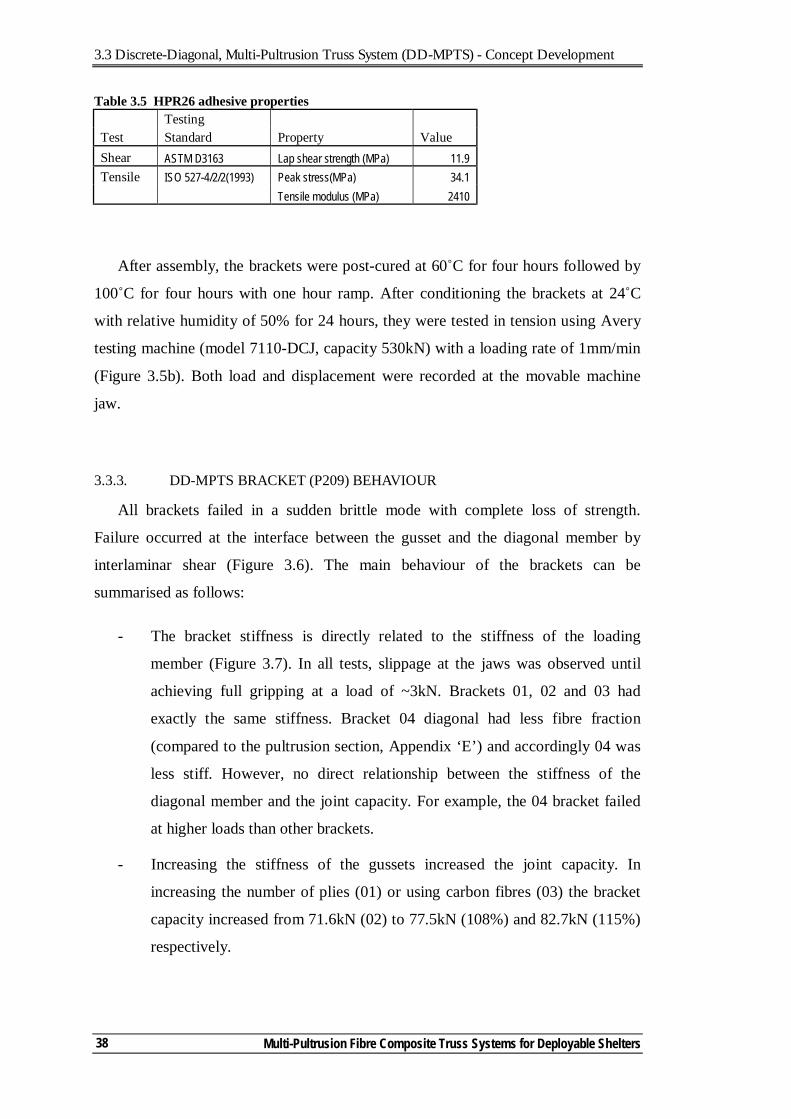
3.3 Discrete-Diagonal, Multi-Pultrusion Truss System (DD-MPTS) - Concept Development
Multi-Pultrusion Fibre Composite Truss Systems for Deployable Shelters
38
Table 3.5 HPR26 adhesive properties Testing Test Standard Property Value Shear ASTM D3163 Lap shear strength (MPa) 11.9 Tensile ISO 527-4/2/2(1993) Peak stress(MPa) 34.1 Tensile modulus (MPa) 2410
After assembly, the brackets were post-cured at 60˚C for four hours followed by
100˚C for four hours with one hour ramp. After conditioning the brackets at 24˚C
with relative humidity of 50% for 24 hours, they were tested in tension using Avery
testing machine (model 7110-DCJ, capacity 530kN) with a loading rate of 1mm/min
(Figure 3.5b). Both load and displacement were recorded at the movable machine
jaw.
3.3.3. DD-MPTS BRACKET (P209) BEHAVIOUR
All brackets failed in a sudden brittle mode with complete loss of strength.
Failure occurred at the interface between the gusset and the diagonal member by
interlaminar shear (Figure 3.6). The main behaviour of the brackets can be
summarised as follows:
- The bracket stiffness is directly related to the stiffness of the loading
member (Figure 3.7). In all tests, slippage at the jaws was observed until
achieving full gripping at a load of ~3kN. Brackets 01, 02 and 03 had
exactly the same stiffness. Bracket 04 diagonal had less fibre fraction
(compared to the pultrusion section, Appendix ‘E’) and accordingly 04 was
less stiff. However, no direct relationship between the stiffness of the
diagonal member and the joint capacity. For example, the 04 bracket failed
at higher loads than other brackets.
- Increasing the stiffness of the gussets increased the joint capacity. In
increasing the number of plies (01) or using carbon fibres (03) the bracket
capacity increased from 71.6kN (02) to 77.5kN (108%) and 82.7kN (115%)
respectively.
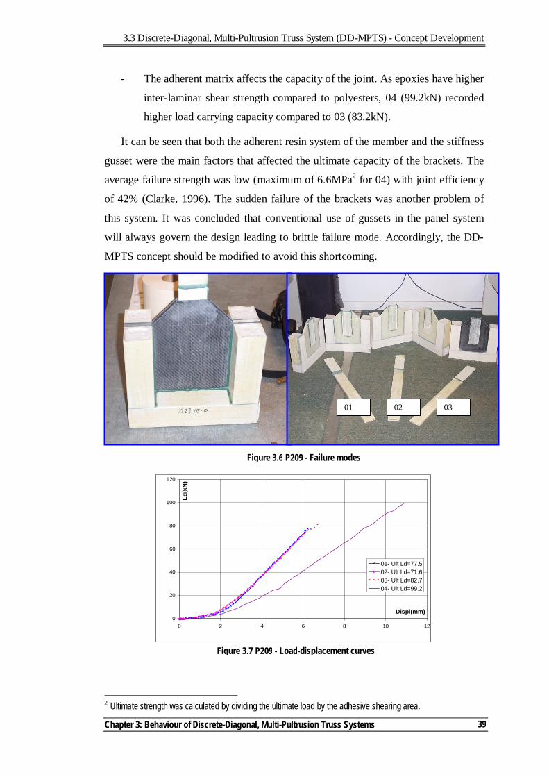
3.3 Discrete-Diagonal, Multi-Pultrusion Truss System (DD-MPTS) - Concept Development
Chapter 3: Behaviour of Discrete-Diagonal, Multi-Pultrusion Truss Systems
39
- The adherent matrix affects the capacity of the joint. As epoxies have higher
inter-laminar shear strength compared to polyesters, 04 (99.2kN) recorded
higher load carrying capacity compared to 03 (83.2kN).
It can be seen that both the adherent resin system of the member and the stiffness
gusset were the main factors that affected the ultimate capacity of the brackets. The
average failure strength was low (maximum of 6.6MPa2 for 04) with joint efficiency
of 42% (Clarke, 1996). The sudden failure of the brackets was another problem of
this system. It was concluded that conventional use of gussets in the panel system
will always govern the design leading to brittle failure mode. Accordingly, the DD-
MPTS concept should be modified to avoid this shortcoming.
2 Ultimate strength was calculated by dividing the ultimate load by the adhesive shearing area.
Figure 3.6 P209 - Failure modes
01 02 03
Figure 3.7 P209 - Load-displacement curves
0
20
40
60
80
100
120
0 2 4 6 8 10 12
Displ(mm)
Ld(k
N)
01- Ult Ld=77.502- Ult Ld=71.603- Ult Ld=82.704- Ult Ld=99.2
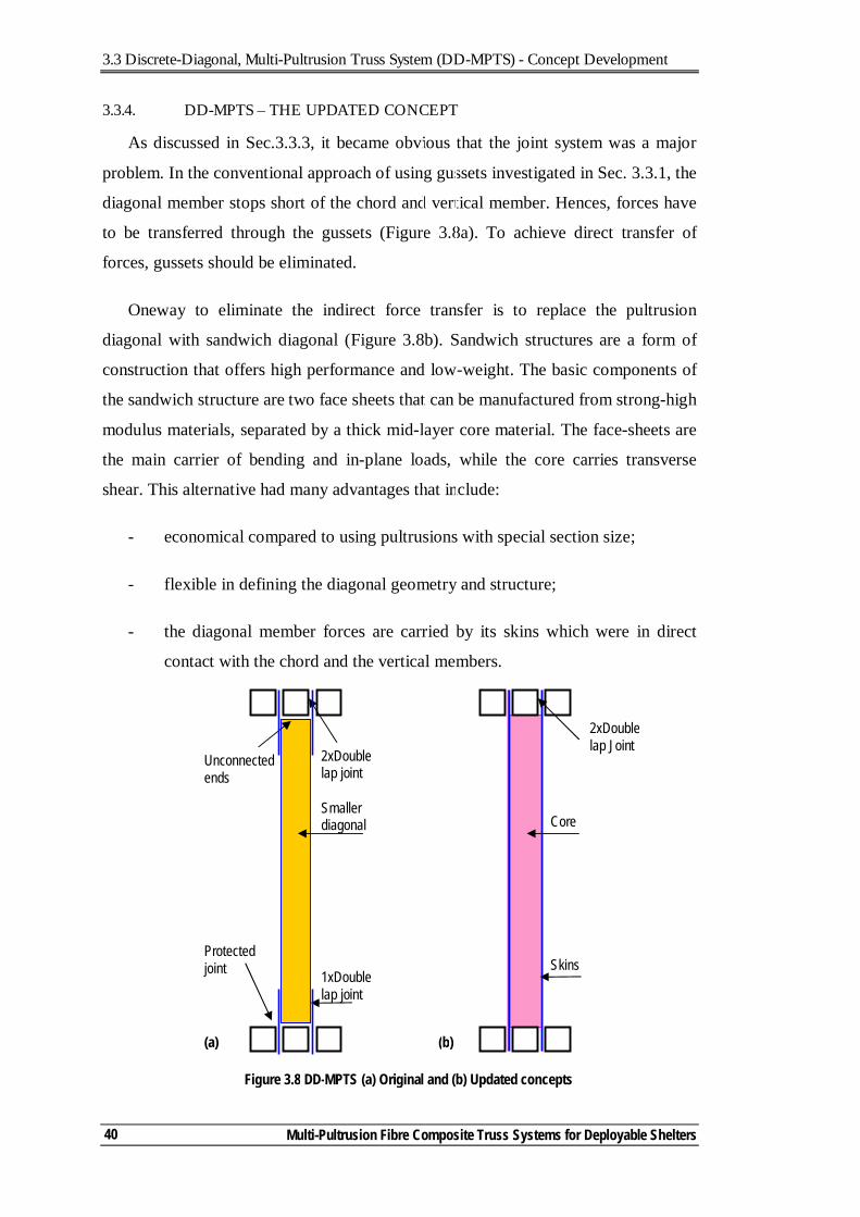
3.3 Discrete-Diagonal, Multi-Pultrusion Truss System (DD-MPTS) - Concept Development
Multi-Pultrusion Fibre Composite Truss Systems for Deployable Shelters
40
3.3.4. DD-MPTS – THE UPDATED CONCEPT
As discussed in Sec.3.3.3, it became obvious that the joint system was a major
problem. In the conventional approach of using gussets investigated in Sec. 3.3.1, the
diagonal member stops short of the chord and vertical member. Hences, forces have
to be transferred through the gussets (Figure 3.8a). To achieve direct transfer of
forces, gussets should be eliminated.
Oneway to eliminate the indirect force transfer is to replace the pultrusion
diagonal with sandwich diagonal (Figure 3.8b). Sandwich structures are a form of
construction that offers high performance and low-weight. The basic components of
the sandwich structure are two face sheets that can be manufactured from strong-high
modulus materials, separated by a thick mid-layer core material. The face-sheets are
the main carrier of bending and in-plane loads, while the core carries transverse
shear. This alternative had many advantages that include:
- economical compared to using pultrusions with special section size;
- flexible in defining the diagonal geometry and structure;
- the diagonal member forces are carried by its skins which were in direct
contact with the chord and the vertical members.
Skins
2xDouble lap Joint
Core
Figure 3.8 DD-MPTS (a) Original and (b) Updated concepts
1xDouble lap joint
2xDouble lap joint
Smaller diagonal
Protected joint
Unconnected ends
(a) (b)
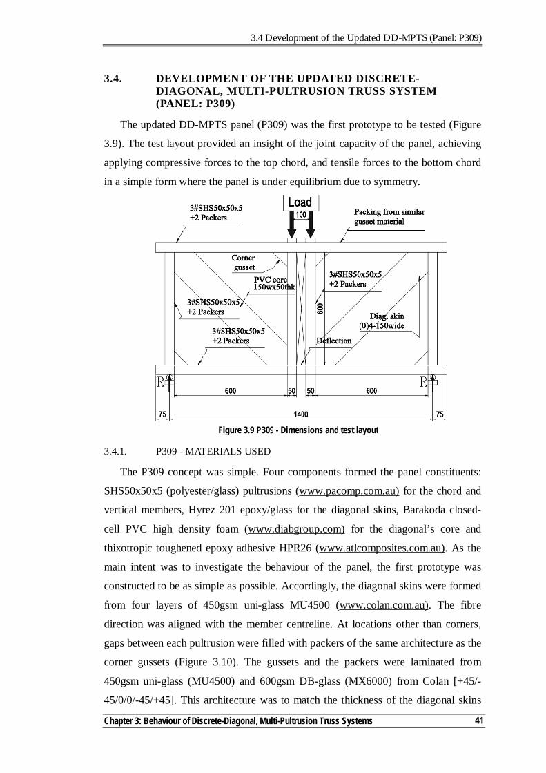
3.4 Development of the Updated DD-MPTS (Panel: P309)
Chapter 3: Behaviour of Discrete-Diagonal, Multi-Pultrusion Truss Systems
41
3.4. DEVELOPMENT OF THE UPDATED DISCRETE-DIAGONAL, MULTI-PULTRUSION TRUSS SYSTEM (PANEL: P309)
The updated DD-MPTS panel (P309) was the first prototype to be tested (Figure
3.9). The test layout provided an insight of the joint capacity of the panel, achieving
applying compressive forces to the top chord, and tensile forces to the bottom chord
in a simple form where the panel is under equilibrium due to symmetry.
3.4.1. P309 - MATERIALS USED
The P309 concept was simple. Four components formed the panel constituents:
SHS50x50x5 (polyester/glass) pultrusions (www.pacomp.com.au) for the chord and
vertical members, Hyrez 201 epoxy/glass for the diagonal skins, Barakoda closed-
cell PVC high density foam (www.diabgroup.com) for the diagonal’s core and
thixotropic toughened epoxy adhesive HPR26 (www.atlcomposites.com.au). As the
main intent was to investigate the behaviour of the panel, the first prototype was
constructed to be as simple as possible. Accordingly, the diagonal skins were formed
from four layers of 450gsm uni-glass MU4500 (www.colan.com.au). The fibre
direction was aligned with the member centreline. At locations other than corners,
gaps between each pultrusion were filled with packers of the same architecture as the
corner gussets (Figure 3.10). The gussets and the packers were laminated from
450gsm uni-glass (MU4500) and 600gsm DB-glass (MX6000) from Colan [+45/-
45/0/0/-45/+45]. This architecture was to match the thickness of the diagonal skins
Figure 3.9 P309 - Dimensions and test layout
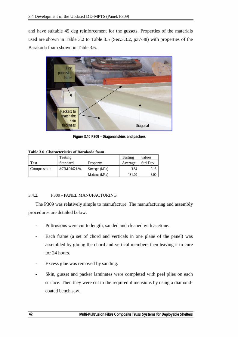
3.4 Development of the Updated DD-MPTS (Panel: P309)
Multi-Pultrusion Fibre Composite Truss Systems for Deployable Shelters
42
and have suitable 45 deg reinforcement for the gussets. Properties of the materials
used are shown in Table 3.2 to Table 3.5 (Sec.3.3.2, p37-38) with properties of the
Barakoda foam shown in Table 3.6.
Table 3.6 Characteristics of Barakoda foam Testing Testing values Test Standard Property Average Std Dev Compression ASTM D1621-94 Strength (MPa) 3.54 0.15 Modulus (MPa) 131.00 5.00
3.4.2. P309 - PANEL MANUFACTURING
The P309 was relatively simple to manufacture. The manufacturing and assembly
procedures are detailed below:
- Pultrusions were cut to length, sanded and cleaned with acetone.
- Each frame (a set of chord and verticals in one plane of the panel) was
assembled by gluing the chord and vertical members then leaving it to cure
for 24 hours.
- Excess glue was removed by sanding.
- Skin, gusset and packer laminates were completed with peel plies on each
surface. Then they were cut to the required dimensions by using a diamond-
coated bench saw.
Figure 3.10 P309 – Diagonal skins and packers
Packers to match the
skin thickness Diagonal
First pultrusion
frame
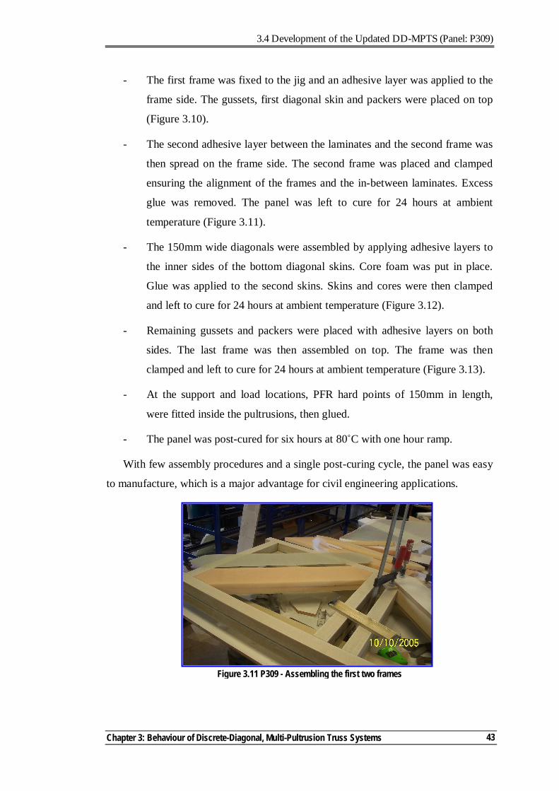
3.4 Development of the Updated DD-MPTS (Panel: P309)
Chapter 3: Behaviour of Discrete-Diagonal, Multi-Pultrusion Truss Systems
43
- The first frame was fixed to the jig and an adhesive layer was applied to the
frame side. The gussets, first diagonal skin and packers were placed on top
(Figure 3.10).
- The second adhesive layer between the laminates and the second frame was
then spread on the frame side. The second frame was placed and clamped
ensuring the alignment of the frames and the in-between laminates. Excess
glue was removed. The panel was left to cure for 24 hours at ambient
temperature (Figure 3.11).
- The 150mm wide diagonals were assembled by applying adhesive layers to
the inner sides of the bottom diagonal skins. Core foam was put in place.
Glue was applied to the second skins. Skins and cores were then clamped
and left to cure for 24 hours at ambient temperature (Figure 3.12).
- Remaining gussets and packers were placed with adhesive layers on both
sides. The last frame was then assembled on top. The frame was then
clamped and left to cure for 24 hours at ambient temperature (Figure 3.13).
- At the support and load locations, PFR hard points of 150mm in length,
were fitted inside the pultrusions, then glued.
- The panel was post-cured for six hours at 80˚C with one hour ramp.
With few assembly procedures and a single post-curing cycle, the panel was easy
to manufacture, which is a major advantage for civil engineering applications.
Figure 3.11 P309 - Assembling the first two frames
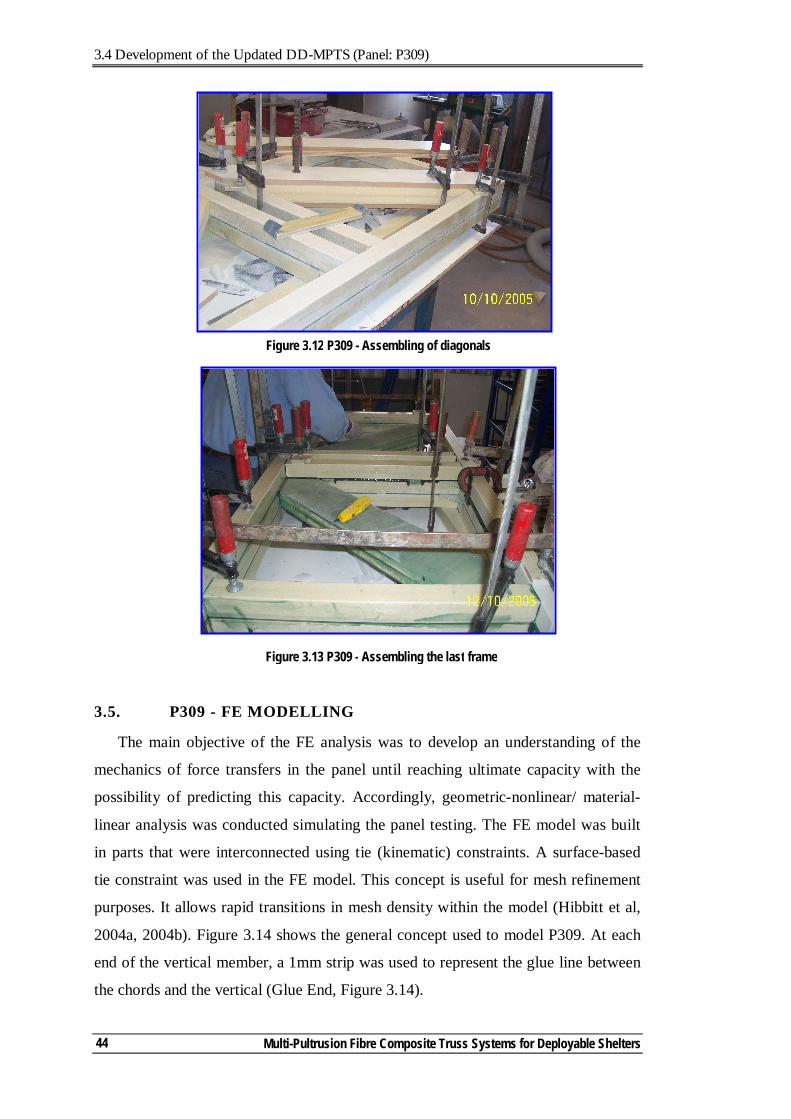
3.4 Development of the Updated DD-MPTS (Panel: P309)
Multi-Pultrusion Fibre Composite Truss Systems for Deployable Shelters
44
3.5. P309 - FE MODELLING
The main objective of the FE analysis was to develop an understanding of the
mechanics of force transfers in the panel until reaching ultimate capacity with the
possibility of predicting this capacity. Accordingly, geometric-nonlinear/ material-
linear analysis was conducted simulating the panel testing. The FE model was built
in parts that were interconnected using tie (kinematic) constraints. A surface-based
tie constraint was used in the FE model. This concept is useful for mesh refinement
purposes. It allows rapid transitions in mesh density within the model (Hibbitt et al,
2004a, 2004b). Figure 3.14 shows the general concept used to model P309. At each
end of the vertical member, a 1mm strip was used to represent the glue line between
the chords and the vertical (Glue End, Figure 3.14).
Figure 3.13 P309 - Assembling the last frame
Figure 3.12 P309 - Assembling of diagonals
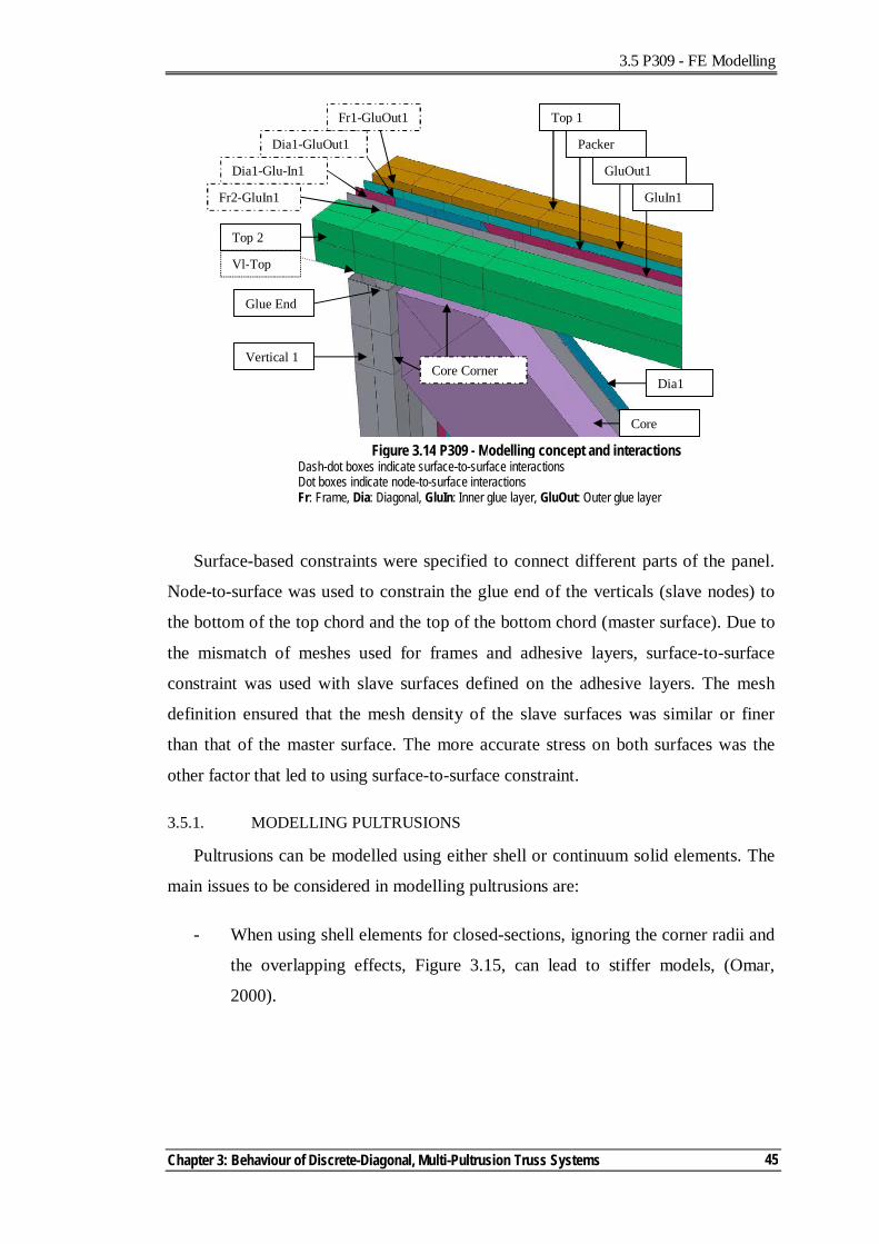
3.5 P309 - FE Modelling
Chapter 3: Behaviour of Discrete-Diagonal, Multi-Pultrusion Truss Systems
45
Surface-based constraints were specified to connect different parts of the panel.
Node-to-surface was used to constrain the glue end of the verticals (slave nodes) to
the bottom of the top chord and the top of the bottom chord (master surface). Due to
the mismatch of meshes used for frames and adhesive layers, surface-to-surface
constraint was used with slave surfaces defined on the adhesive layers. The mesh
definition ensured that the mesh density of the slave surfaces was similar or finer
than that of the master surface. The more accurate stress on both surfaces was the
other factor that led to using surface-to-surface constraint.
3.5.1. MODELLING PULTRUSIONS
Pultrusions can be modelled using either shell or continuum solid elements. The
main issues to be considered in modelling pultrusions are:
- When using shell elements for closed-sections, ignoring the corner radii and
the overlapping effects, Figure 3.15, can lead to stiffer models, (Omar,
2000).
Top 2
GluIn1
GluOut1
Packer
Top 1
Vertical 1
Glue End
Dia1
Core
Fr1-GluOut1
Dia1-GluOut1
Dia1-Glu-In1
Fr2-GluIn1
Figure 3.14 P309 - Modelling concept and interactions Dash-dot boxes indicate surface-to-surface interactions Dot boxes indicate node-to-surface interactions Fr: Frame, Dia: Diagonal, GluIn: Inner glue layer, GluOut: Outer glue layer
Vl-Top
Core Corner
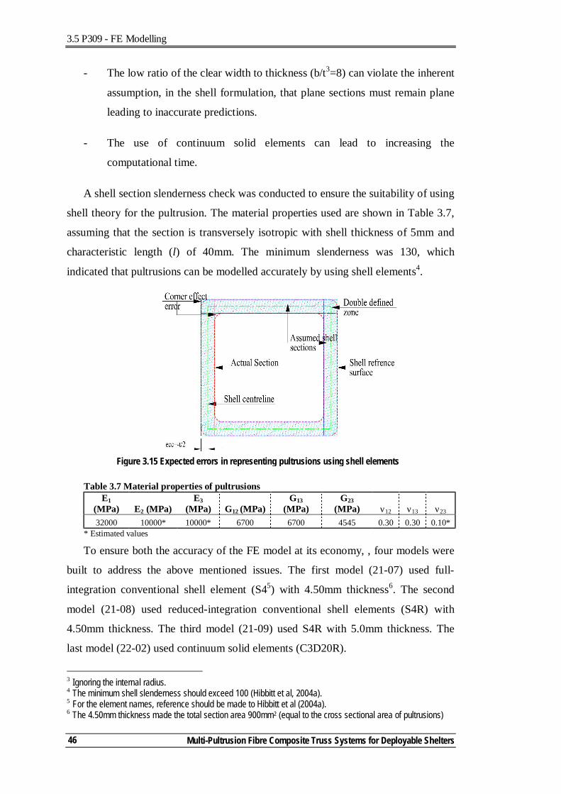
3.5 P309 - FE Modelling
Multi-Pultrusion Fibre Composite Truss Systems for Deployable Shelters
46
- The low ratio of the clear width to thickness (b/t3=8) can violate the inherent
assumption, in the shell formulation, that plane sections must remain plane
leading to inaccurate predictions.
- The use of continuum solid elements can lead to increasing the
computational time.
A shell section slenderness check was conducted to ensure the suitability of using
shell theory for the pultrusion. The material properties used are shown in Table 3.7,
assuming that the section is transversely isotropic with shell thickness of 5mm and
characteristic length (l) of 40mm. The minimum slenderness was 130, which
indicated that pultrusions can be modelled accurately by using shell elements4.
Table 3.7 Material properties of pultrusions E1
(MPa) E2 (MPa) E3
(MPa) G12 (MPa) G13
(MPa) G23
(MPa) ν12 ν13 ν23 32000 10000* 10000* 6700 6700 4545 0.30 0.30 0.10*
* Estimated values
To ensure both the accuracy of the FE model at its economy, , four models were
built to address the above mentioned issues. The first model (21-07) used full-
integration conventional shell element (S45) with 4.50mm thickness6. The second
model (21-08) used reduced-integration conventional shell elements (S4R) with
4.50mm thickness. The third model (21-09) used S4R with 5.0mm thickness. The
last model (22-02) used continuum solid elements (C3D20R).
3 Ignoring the internal radius. 4 The minimum shell slenderness should exceed 100 (Hibbitt et al, 2004a). 5 For the element names, reference should be made to Hibbitt et al (2004a). 6 The 4.50mm thickness made the total section area 900mm2 (equal to the cross sectional area of pultrusions)
Figure 3.15 Expected errors in representing pultrusions using shell elements
3.5 P309 - FE Modelling
Chapter 3: Behaviour of Discrete-Diagonal, Multi-Pultrusion Truss Systems
47
A trade-off between the mesh density and the model performance is usually
required. A few alternatives were investigated to assess the required mesh density. It
was found that using four elements per each section side provided reasonable
representation of the section, when compared to finer meshes. The aspect ratio of the
element was about 1 at corners but did not exceed 2 in other locations7.
3.5.2. MODELLING DIAGONALS
The sandwich diagonal was more complicated than other model parts. FE
numerical solutions have been implemented to assess the stress and strain
distributions in sandwich structures.
Vannucci et al (1998) conducted a comparison between the performance of some
theories and FE models of sandwich plates and shells. Compared with Pagano (1970)
for square and rectangular plates, they concluded that using discrete-shear
quadrilateral elements, based on the theory of Mindlin-Reissner for the analysis of
thick plates, provided the best response with results within 20% of the exact solution.
Akfert (1994) used the commercial FE package (Abaqus) with a foam material
model based on a volumetric hardening model as described by Gibson et al (1982)
Maiti et al (1984), and Gibson et al (1997), with skins, adhesive layers and core
materials modelled as plain strain two-dimensional continuum elements.
Muc and Zuchara (2000) investigated the buckling and failure analysis of thin-
walled composite sandwich plates. Their 2-D geometrical nonlinear formulation was
found to correlate well with the 3-D FE analysis. Shell elements were used for the
sandwich skins while 3-D solid (20 nodes brick) elements were used to model the
core. This approach was found to be quite effective for static and impact problems
(Haug and Jamjian, 1996).
Bazant and Beghini (2004), in using variational analysis and comparing them
with standard FE model predictions, concluded that it is correct to simulate soft-core
sandwich structures with the standard FE programs using Lagrangian updating
7 At corners finer mesh was used due to high stress gradients.
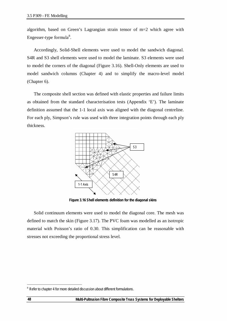
3.5 P309 - FE Modelling
Multi-Pultrusion Fibre Composite Truss Systems for Deployable Shelters
48
algorithm, based on Green’s Lagrangian strain tensor of m=2 which agree with
Engesser-type formula8.
Accordingly, Solid-Shell elements were used to model the sandwich diagonal.
S4R and S3 shell elements were used to model the laminate. S3 elements were used
to model the corners of the diagonal (Figure 3.16). Shell-Only elements are used to
model sandwich columns (Chapter 4) and to simplify the macro-level model
(Chapter 6).
The composite shell section was defined with elastic properties and failure limits
as obtained from the standard characterisation tests (Appendix ‘E’). The laminate
definition assumed that the 1-1 local axis was aligned with the diagonal centreline.
For each ply, Simpson’s rule was used with three integration points through each ply
thickness.
Solid continuum elements were used to model the diagonal core. The mesh was
defined to match the skin (Figure 3.17). The PVC foam was modelled as an isotropic
material with Poisson’s ratio of 0.30. This simplification can be reasonable with
stresses not exceeding the proportional stress level.
8 Refer to chapter 4 for more detailed discussion about different formulations.
S3
S4R
Figure 3.16 Shell elements definition for the diagonal skins
1-1 Axis
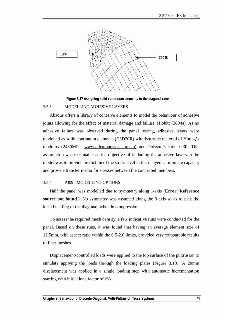
3.5 P309 - FE Modelling
Chapter 3: Behaviour of Discrete-Diagonal, Multi-Pultrusion Truss Systems
49
3.5.3. MODELLING ADHESIVE LAYERS
Abaqus offers a library of cohesive elements to model the behaviour of adhesive
joints allowing for the effect of material damage and failure, Hibbitt (2004a). As no
adhesive failure was observed during the panel testing, adhesive layers were
modelled as solid continuum elements (C3D20R) with isotropic material of Young’s
modulus (2430MPa, www.atlcomposites.com.au) and Poisson’s ratio 0.30. This
assumption was reasonable as the objective of including the adhesive layers in the
model was to provide prediction of the stress level in these layers at ultimate capacity
and provide transfer media for stresses between the connected members.
3.5.4. P309 - MODELLING OPTIONS
Half the panel was modelled due to symmetry along 1-axis (Error! Reference
source not found.). No symmetry was assumed along the 3-axis so as to pick the
local buckling of the diagonal, when in compression.
To assess the required mesh density, a few indicative runs were conducted for the
panel. Based on these runs, it was found that having an average element size of
12.5mm, with aspect ratio within the 0.5-2.0 limits, provided very comparable results
to finer meshes.
Displacement-controlled loads were applied to the top surface of the pultrusion to
simulate applying the loads through the loading plates (Figure 3.18). A 20mm
displacement was applied in a single loading step with automatic incrementation
starting with initial load factor of 2%.
C3D8R C3D6
Figure 3.17 Assigning solid continuum elements to the diagonal core
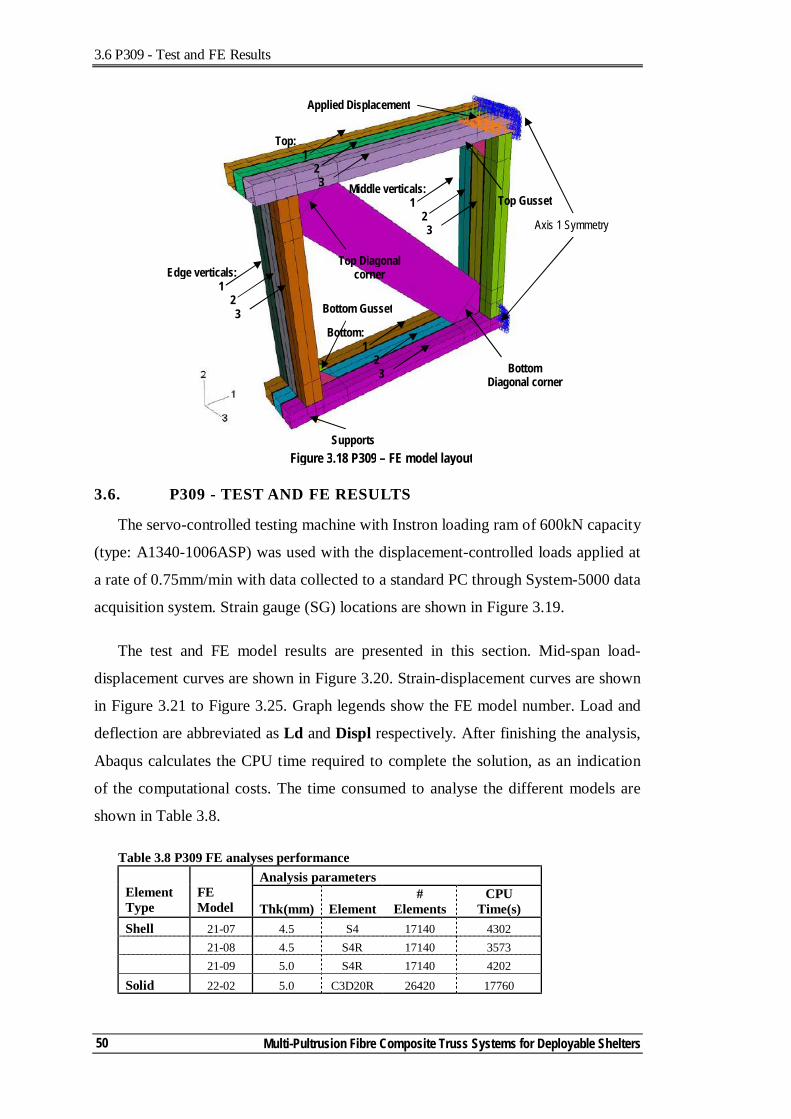
3.6 P309 - Test and FE Results
Multi-Pultrusion Fibre Composite Truss Systems for Deployable Shelters
50
3.6. P309 - TEST AND FE RESULTS
The servo-controlled testing machine with Instron loading ram of 600kN capacity
(type: A1340-1006ASP) was used with the displacement-controlled loads applied at
a rate of 0.75mm/min with data collected to a standard PC through System-5000 data
acquisition system. Strain gauge (SG) locations are shown in Figure 3.19.
The test and FE model results are presented in this section. Mid-span load-
displacement curves are shown in Figure 3.20. Strain-displacement curves are shown
in Figure 3.21 to Figure 3.25. Graph legends show the FE model number. Load and
deflection are abbreviated as Ld and Displ respectively. After finishing the analysis,
Abaqus calculates the CPU time required to complete the solution, as an indication
of the computational costs. The time consumed to analyse the different models are
shown in Table 3.8.
Table 3.8 P309 FE analyses performance Analysis parameters
Element Type
FE Model Thk(mm) Element
# Elements
CPU Time(s)
Shell 21-07 4.5 S4 17140 4302 21-08 4.5 S4R 17140 3573 21-09 5.0 S4R 17140 4202 Solid 22-02 5.0 C3D20R 26420 17760
Middle verticals: 1
2 3 Axis 1 Symmetry
Applied Displacement
Supports
Bottom Diagonal corner
Top Diagonal corner
Top Gusset
Bottom Gusset
Edge verticals: 1
2 3
Top: 1
2 3
Bottom: 1
2 3
Figure 3.18 P309 – FE model layout
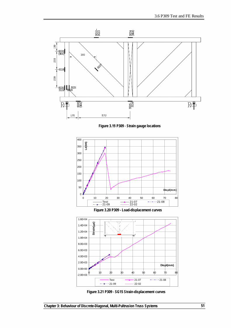
3.6 P309 Test and FE Results
Chapter 3: Behaviour of Discrete-Diagonal, Multi-Pultrusion Truss Systems
51
Figure 3.20 P309 - Load-displacement curves
0
50
100
150
200
250
300
350
400
0 10 20 30 40 50 60 70 80
Displ(mm)
Ld(k
N)
Test 21-07 21-0821-09 22-02
Figure 3.19 P309 - Strain gauge locations
Figure 3.21 P309 - SG15 Strain-displacement curves
-2.0E+03
0.0E+00
2.0E+03
4.0E+03
6.0E+03
8.0E+03
1.0E+04
1.2E+04
1.4E+04
1.6E+04
0 10 20 30 40 50 60 70 80
Displ(mm)
Stra
in( µ
s)
Test 21-07 21-0821-09 22-02
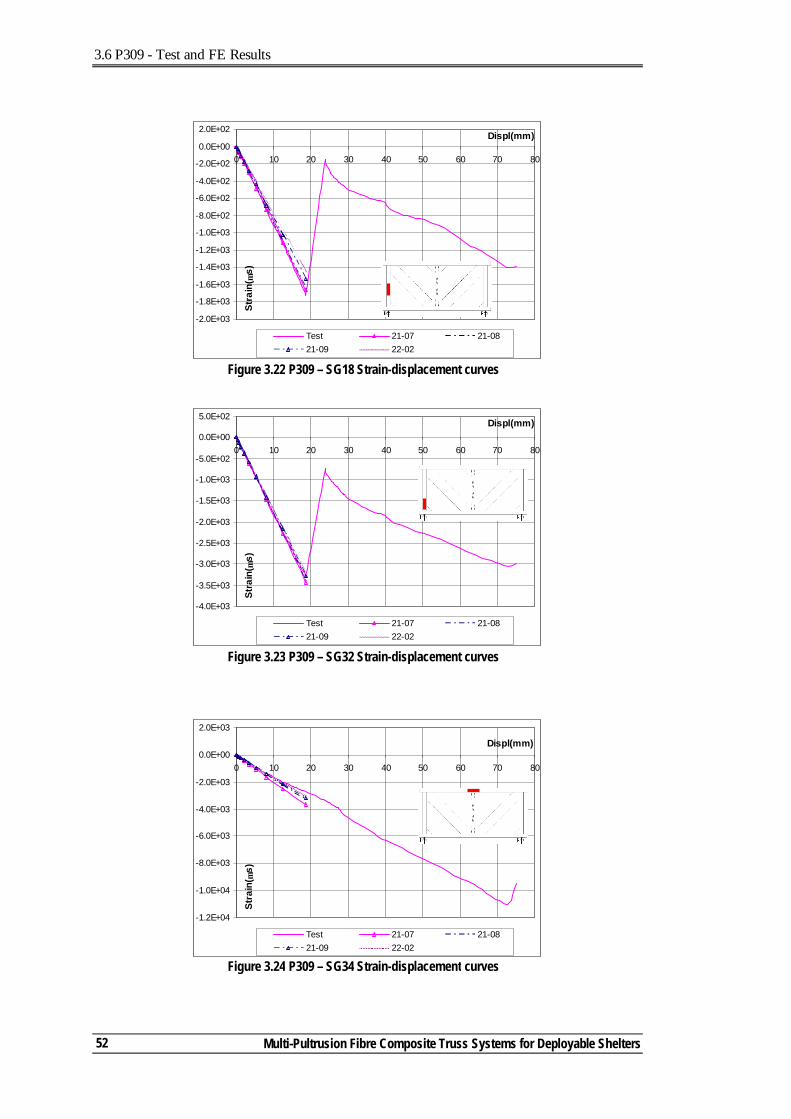
3.6 P309 - Test and FE Results
Multi-Pultrusion Fibre Composite Truss Systems for Deployable Shelters
52
Figure 3.23 P309 – SG32 Strain-displacement curves
-4.0E+03
-3.5E+03
-3.0E+03
-2.5E+03
-2.0E+03
-1.5E+03
-1.0E+03
-5.0E+02
0.0E+00
5.0E+02
0 10 20 30 40 50 60 70 80
Displ(mm)
Stra
in( µ
s)
Test 21-07 21-0821-09 22-02
Figure 3.22 P309 – SG18 Strain-displacement curves
-2.0E+03
-1.8E+03
-1.6E+03
-1.4E+03
-1.2E+03
-1.0E+03
-8.0E+02
-6.0E+02
-4.0E+02
-2.0E+02
0.0E+00
2.0E+02
0 10 20 30 40 50 60 70 80
Displ(mm)
Stra
in( µ
s)
Test 21-07 21-0821-09 22-02
Figure 3.24 P309 – SG34 Strain-displacement curves
-1.2E+04
-1.0E+04
-8.0E+03
-6.0E+03
-4.0E+03
-2.0E+03
0.0E+00
2.0E+03
0 10 20 30 40 50 60 70 80
Displ(mm)
Stra
in( µ
s)
Test 21-07 21-0821-09 22-02
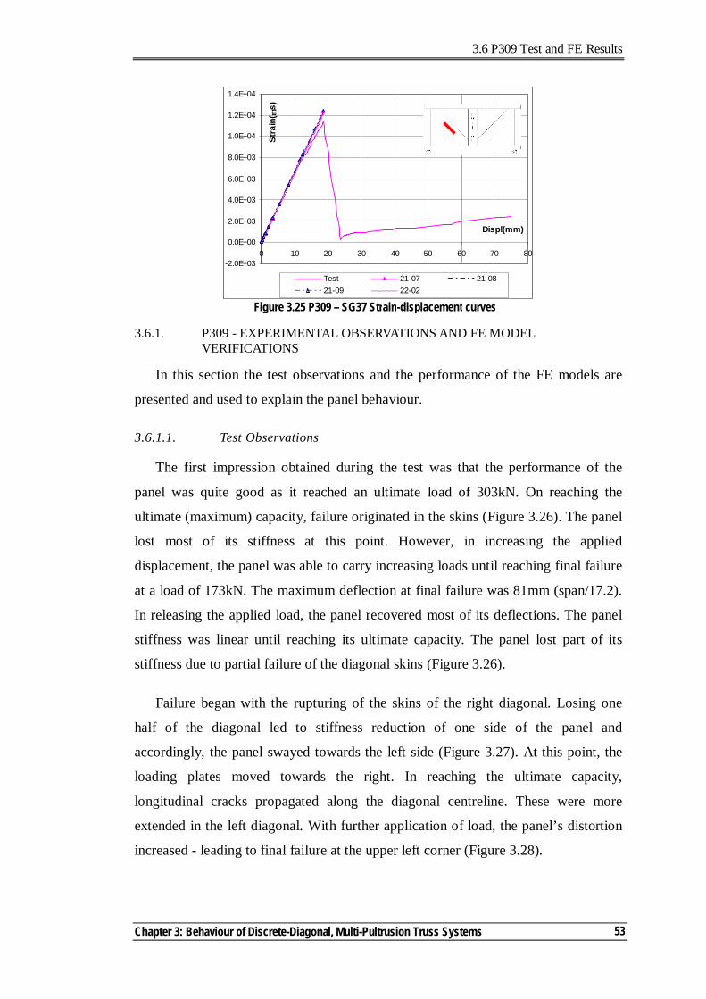
3.6 P309 Test and FE Results
Chapter 3: Behaviour of Discrete-Diagonal, Multi-Pultrusion Truss Systems
53
3.6.1. P309 - EXPERIMENTAL OBSERVATIONS AND FE MODEL VERIFICATIONS
In this section the test observations and the performance of the FE models are
presented and used to explain the panel behaviour.
3.6.1.1. Test Observations
The first impression obtained during the test was that the performance of the
panel was quite good as it reached an ultimate load of 303kN. On reaching the
ultimate (maximum) capacity, failure originated in the skins (Figure 3.26). The panel
lost most of its stiffness at this point. However, in increasing the applied
displacement, the panel was able to carry increasing loads until reaching final failure
at a load of 173kN. The maximum deflection at final failure was 81mm (span/17.2).
In releasing the applied load, the panel recovered most of its deflections. The panel
stiffness was linear until reaching its ultimate capacity. The panel lost part of its
stiffness due to partial failure of the diagonal skins (Figure 3.26).
Failure began with the rupturing of the skins of the right diagonal. Losing one
half of the diagonal led to stiffness reduction of one side of the panel and
accordingly, the panel swayed towards the left side (Figure 3.27). At this point, the
loading plates moved towards the right. In reaching the ultimate capacity,
longitudinal cracks propagated along the diagonal centreline. These were more
extended in the left diagonal. With further application of load, the panel’s distortion
increased - leading to final failure at the upper left corner (Figure 3.28).
Figure 3.25 P309 – SG37 Strain-displacement curves
-2.0E+03
0.0E+00
2.0E+03
4.0E+03
6.0E+03
8.0E+03
1.0E+04
1.2E+04
1.4E+04
0 10 20 30 40 50 60 70 80
Displ(mm)
Stra
in( µ
s)Test 21-07 21-0821-09 22-02
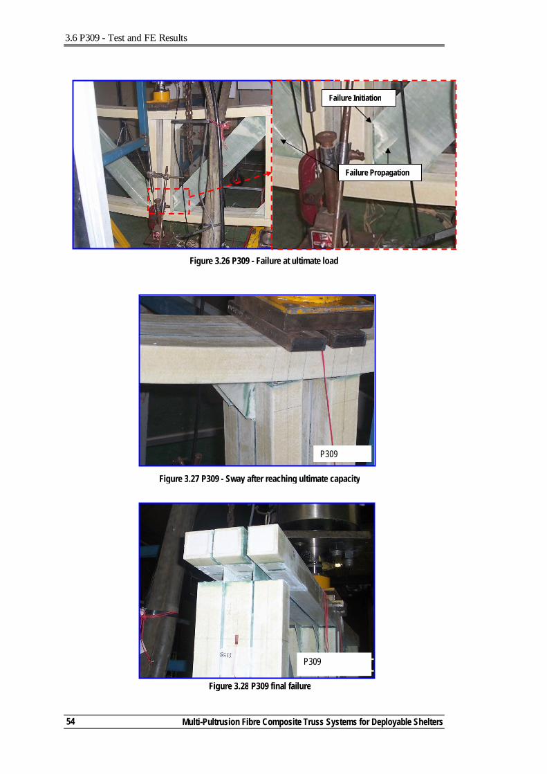
3.6 P309 - Test and FE Results
Multi-Pultrusion Fibre Composite Truss Systems for Deployable Shelters
54
Figure 3.26 P309 - Failure at ultimate load
Failure Initiation
Failure Propagation
Figure 3.27 P309 - Sway after reaching ultimate capacity
P309
Figure 3.28 P309 final failure
P309
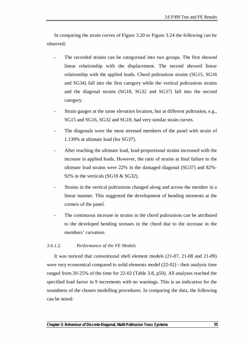
3.6 P309 Test and FE Results
Chapter 3: Behaviour of Discrete-Diagonal, Multi-Pultrusion Truss Systems
55
In comparing the strain curves of Figure 3.20 to Figure 3.24 the following can be
observed:
- The recorded strains can be categorised into two groups. The first showed
linear relationship with the displacement. The second showed linear
relationship with the applied loads. Chord pultrusions strains (SG15, SG16
and SG34) fall into the first category while the vertical pultrusions strains
and the diagonal strains (SG18, SG32 and SG37) fall into the second
category.
- Strain gauges at the same elevation location, but at different pultrusion, e.g.,
SG15 and SG16, SG32 and SG19, had very similar strain curves.
- The diagonals were the most stressed members of the panel with strain of
1.139% at ultimate load (for SG37).
- After reaching the ultimate load, load-proportional strains increased with the
increase in applied loads. However, the ratio of strains at final failure to the
ultimate load strains were 22% in the damaged diagonal (SG37) and 82%-
92% in the verticals (SG18 & SG32).
- Strains in the vertical pultrusions changed along and across the member in a
linear manner. This suggested the development of bending moments at the
corners of the panel.
- The continuous increase in strains in the chord pultrusions can be attributed
to the developed bending stresses in the chord due to the increase in the
members’ curvature.
3.6.1.2. Performance of the FE Models
It was noticed that conventional shell element models (21-07, 21-08 and 21-09)
were very economical compared to solid elements model (22-02) - their analysis time
ranged from 20-25% of the time for 22-02 (Table 3.8, p50). All analyses reached the
specified load factor in 9 increments with no warnings. This is an indication for the
soundness of the chosen modelling procedures. In comparing the data, the following
can be noted:
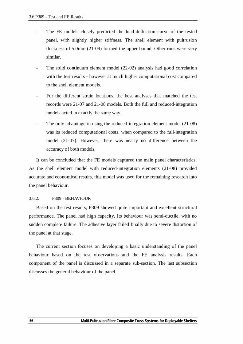
3.6 P309 - Test and FE Results
Multi-Pultrusion Fibre Composite Truss Systems for Deployable Shelters
56
- The FE models closely predicted the load-deflection curve of the tested
panel, with slightly higher stiffness. The shell element with pultrusion
thickness of 5.0mm (21-09) formed the upper bound. Other runs were very
similar.
- The solid continuum element model (22-02) analysis had good correlation
with the test results - however at much higher computational cost compared
to the shell element models.
- For the different strain locations, the best analyses that matched the test
records were 21-07 and 21-08 models. Both the full and reduced-integration
models acted in exactly the same way.
- The only advantage in using the reduced-integration element model (21-08)
was its reduced computational costs, when compared to the full-integration
model (21-07). However, there was nearly no difference between the
accuracy of both models.
It can be concluded that the FE models captured the main panel characteristics.
As the shell element model with reduced-integration elements (21-08) provided
accurate and economical results, this model was used for the remaining research into
the panel behaviour.
3.6.2. P309 - BEHAVIOUR
Based on the test results, P309 showed quite important and excellent structural
performance. The panel had high capacity. Its behaviour was semi-ductile, with no
sudden complete failure. The adhesive layer failed finally due to severe distortion of
the panel at that stage.
The current section focuses on developing a basic understanding of the panel
behaviour based on the test observations and the FE analysis results. Each
component of the panel is discussed in a separate sub-section. The last subsection
discusses the general behaviour of the panel.
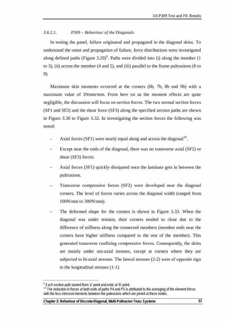
3.6 P309 Test and FE Results
Chapter 3: Behaviour of Discrete-Diagonal, Multi-Pultrusion Truss Systems
57
3.6.2.1. P309 – Behaviour of the Diagonals
In testing the panel, failure originated and propagated in the diagonal skins. To
understand the onset and propagation of failure, force distributions were investigated
along defined paths (Figure 3.29)9. Paths were divided into (i) along the member (1
to 3), (ii) across the member (4 and 5), and (iii) parallel to the frame pultrusions (6 to
9).
Maximum skin moments occurred at the corners (6b, 7b, 8b and 9b) with a
maximum value of 3Nmm/mm. From here on as the moment effects are quite
negligible, the discussion will focus on section forces. The two normal section forces
(SF1 and SF2) and the shear force (SF3) along the specified section paths are shown
in Figure 3.30 to Figure 3.32. In investigating the section forces the following was
noted:
- Axial forces (SF1) were nearly equal along and across the diagonal10.
- Except near the ends of the diagonal, there was no transverse axial (SF2) or
shear (SF3) forces.
- Axial forces (SF1) quickly dissipated once the laminate gets in between the
pultrusions.
- Transverse compressive forces (SF2) were developed near the diagonal
corners. The level of forces varies across the diagonal width (ranged from
100N/mm to 300N/mm).
- The deformed shape for the corners is shown in Figure 3.33. When the
diagonal was under tension, their corners tended to close due to the
difference of stiffness along the connected members (member ends near the
corners have higher stiffness compared to the rest of the member). This
generated transverse confining compressive forces. Consequently, the skins
are mainly under uni-axial stresses, except at corners where they are
subjected to bi-axial stresses. The lateral stresses (2-2) were of opposite sign
to the longitudinal stresses (1-1).
9 Each section path started from ‘a’ point and ends at ‘b’ point. 10 The reduction in forces at both ends of paths P4 and P5 is attributed to the averaging of the element forces with the less-stressed elements between the pultrusions which are joined at these nodes.
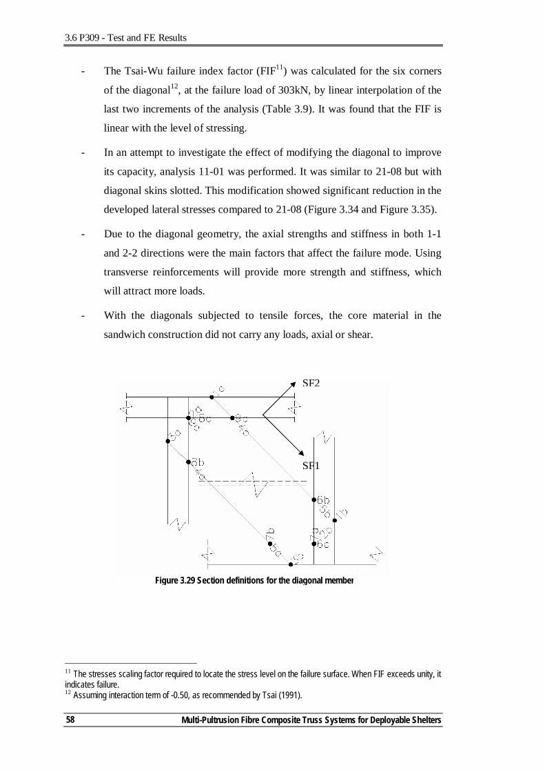
3.6 P309 - Test and FE Results
Multi-Pultrusion Fibre Composite Truss Systems for Deployable Shelters
58
- The Tsai-Wu failure index factor (FIF11) was calculated for the six corners
of the diagonal12, at the failure load of 303kN, by linear interpolation of the
last two increments of the analysis (Table 3.9). It was found that the FIF is
linear with the level of stressing.
- In an attempt to investigate the effect of modifying the diagonal to improve
its capacity, analysis 11-01 was performed. It was similar to 21-08 but with
diagonal skins slotted. This modification showed significant reduction in the
developed lateral stresses compared to 21-08 (Figure 3.34 and Figure 3.35).
- Due to the diagonal geometry, the axial strengths and stiffness in both 1-1
and 2-2 directions were the main factors that affect the failure mode. Using
transverse reinforcements will provide more strength and stiffness, which
will attract more loads.
- With the diagonals subjected to tensile forces, the core material in the
sandwich construction did not carry any loads, axial or shear.
11 The stresses scaling factor required to locate the stress level on the failure surface. When FIF exceeds unity, it indicates failure. 12 Assuming interaction term of -0.50, as recommended by Tsai (1991).
Figure 3.29 Section definitions for the diagonal member
SF1
SF2
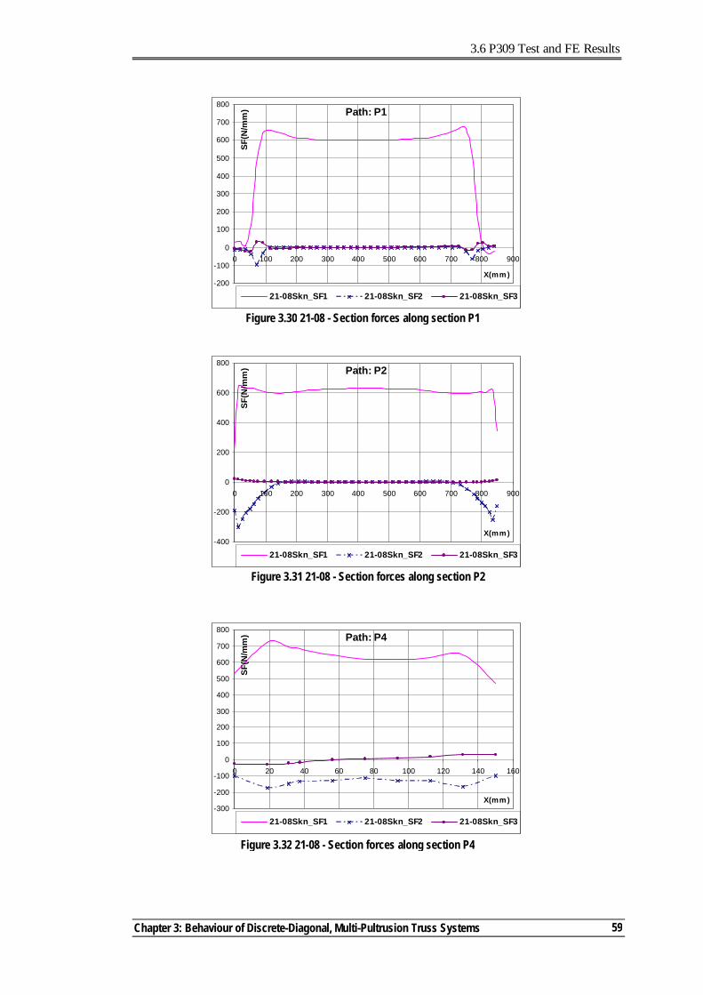
3.6 P309 Test and FE Results
Chapter 3: Behaviour of Discrete-Diagonal, Multi-Pultrusion Truss Systems
59
Path: P1
-200
-100
0
100
200
300
400
500
600
700
800
0 100 200 300 400 500 600 700 800 900
X(mm )
SF(N
/mm
)
21-08Skn_SF1 21-08Skn_SF2 21-08Skn_SF3
Figure 3.30 21-08 - Section forces along section P1
Figure 3.31 21-08 - Section forces along section P2
Path: P2
-400
-200
0
200
400
600
800
0 100 200 300 400 500 600 700 800 900
X(mm )
SF(N
/mm
)
21-08Skn_SF1 21-08Skn_SF2 21-08Skn_SF3
Figure 3.32 21-08 - Section forces along section P4
Path: P4
-300
-200
-100
0
100
200
300
400
500
600
700
800
0 20 40 60 80 100 120 140 160
X(mm )
SF(N
/mm
)
21-08Skn_SF1 21-08Skn_SF2 21-08Skn_SF3
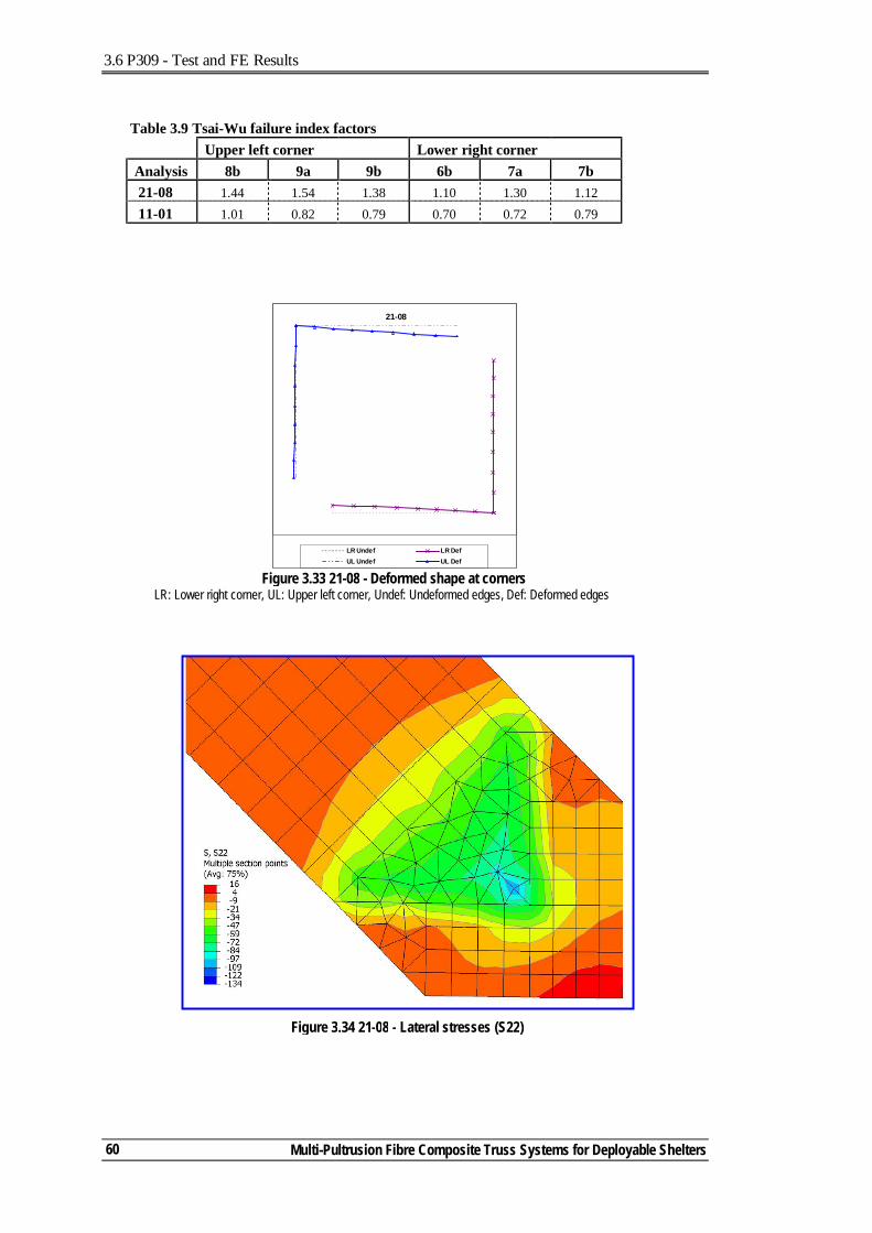
3.6 P309 - Test and FE Results
Multi-Pultrusion Fibre Composite Truss Systems for Deployable Shelters
60
Table 3.9 Tsai-Wu failure index factors Upper left corner Lower right corner Analysis 8b 9a 9b 6b 7a 7b 21-08 1.44 1.54 1.38 1.10 1.30 1.12 11-01 1.01 0.82 0.79 0.70 0.72 0.79
Figure 3.33 21-08 - Deformed shape at corners LR: Lower right corner, UL: Upper left corner, Undef: Undeformed edges, Def: Deformed edges
21-08
LR Undef LR DefUL Undef UL Def
Figure 3.34 21-08 - Lateral stresses (S22)
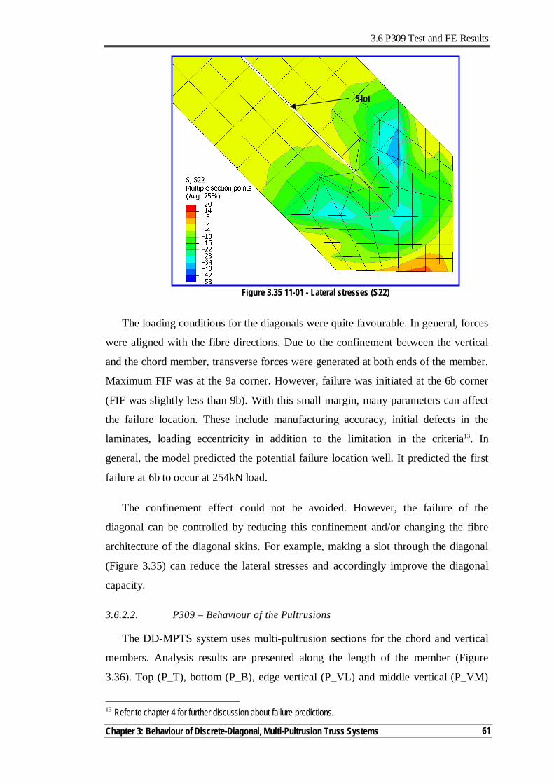
3.6 P309 Test and FE Results
Chapter 3: Behaviour of Discrete-Diagonal, Multi-Pultrusion Truss Systems
61
The loading conditions for the diagonals were quite favourable. In general, forces
were aligned with the fibre directions. Due to the confinement between the vertical
and the chord member, transverse forces were generated at both ends of the member.
Maximum FIF was at the 9a corner. However, failure was initiated at the 6b corner
(FIF was slightly less than 9b). With this small margin, many parameters can affect
the failure location. These include manufacturing accuracy, initial defects in the
laminates, loading eccentricity in addition to the limitation in the criteria13. In
general, the model predicted the potential failure location well. It predicted the first
failure at 6b to occur at 254kN load.
The confinement effect could not be avoided. However, the failure of the
diagonal can be controlled by reducing this confinement and/or changing the fibre
architecture of the diagonal skins. For example, making a slot through the diagonal
(Figure 3.35) can reduce the lateral stresses and accordingly improve the diagonal
capacity.
3.6.2.2. P309 – Behaviour of the Pultrusions
The DD-MPTS system uses multi-pultrusion sections for the chord and vertical
members. Analysis results are presented along the length of the member (Figure
3.36). Top (P_T), bottom (P_B), edge vertical (P_VL) and middle vertical (P_VM)
13 Refer to chapter 4 for further discussion about failure predictions.
Figure 3.35 11-01 - Lateral stresses (S22)
Slot
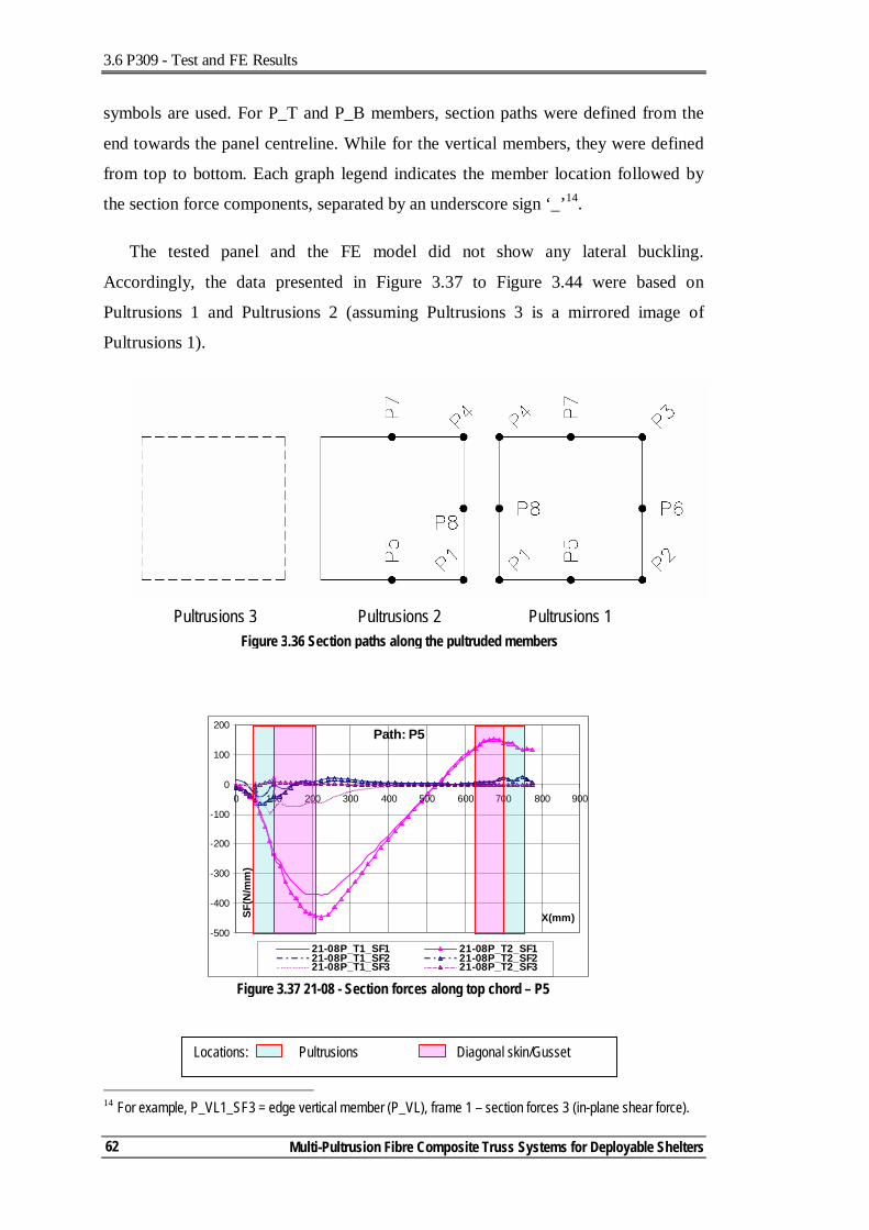
3.6 P309 - Test and FE Results
Multi-Pultrusion Fibre Composite Truss Systems for Deployable Shelters
62
symbols are used. For P_T and P_B members, section paths were defined from the
end towards the panel centreline. While for the vertical members, they were defined
from top to bottom. Each graph legend indicates the member location followed by
the section force components, separated by an underscore sign ‘_’14.
The tested panel and the FE model did not show any lateral buckling.
Accordingly, the data presented in Figure 3.37 to Figure 3.44 were based on
Pultrusions 1 and Pultrusions 2 (assuming Pultrusions 3 is a mirrored image of
Pultrusions 1).
14 For example, P_VL1_SF3 = edge vertical member (P_VL), frame 1 – section forces 3 (in-plane shear force).
Path: P5
-500
-400
-300
-200
-100
0
100
200
0 100 200 300 400 500 600 700 800 900
X(mm)SF(N
/mm
)
21-08P_T1_SF1 21-08P_T2_SF121-08P_T1_SF2 21-08P_T2_SF221-08P_T1_SF3 21-08P_T2_SF3
Figure 3.37 21-08 - Section forces along top chord – P5
Figure 3.36 Section paths along the pultruded members Pultrusions 1 Pultrusions 2 Pultrusions 3
Locations: Pultrusions Diagonal skin/Gusset
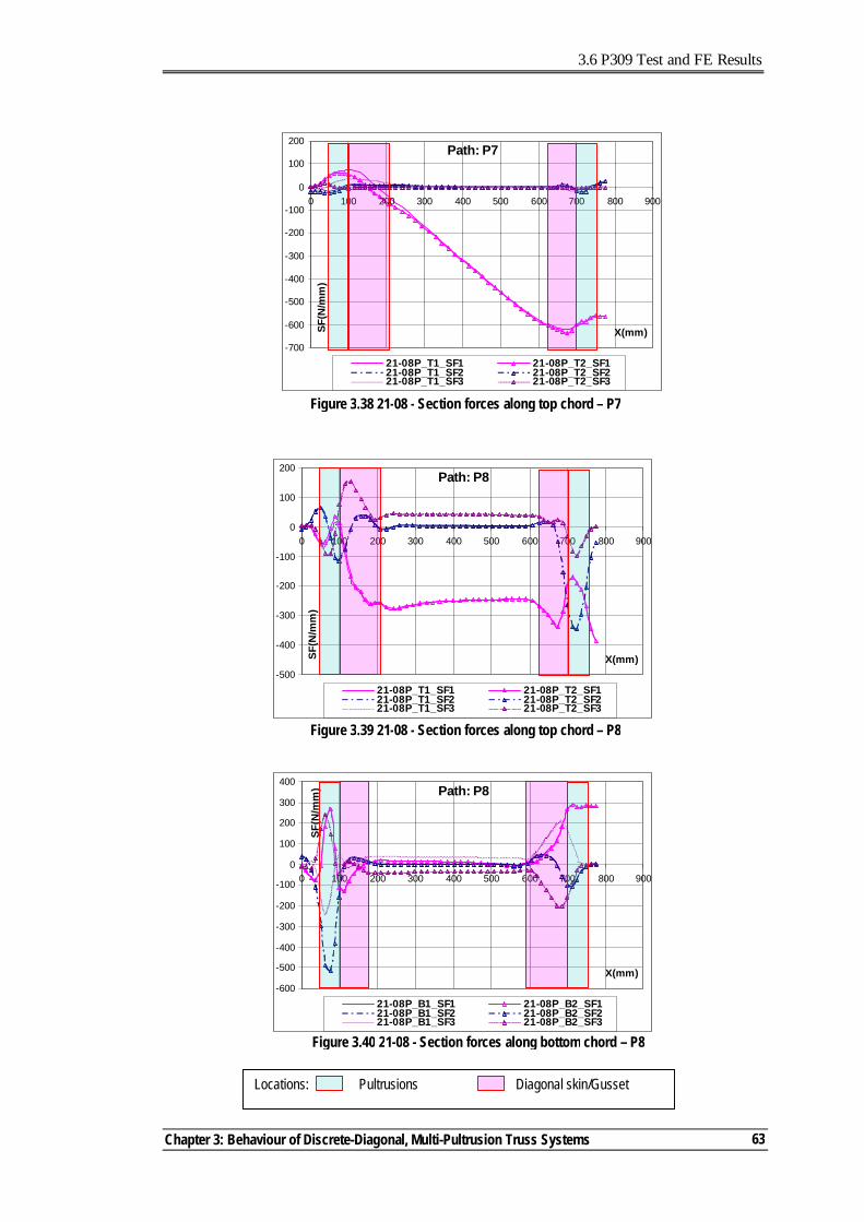
3.6 P309 Test and FE Results
Chapter 3: Behaviour of Discrete-Diagonal, Multi-Pultrusion Truss Systems
63
Path: P7
-700
-600
-500
-400
-300
-200
-100
0
100
200
0 100 200 300 400 500 600 700 800 900
X(mm)SF(N
/mm
)
21-08P_T1_SF1 21-08P_T2_SF121-08P_T1_SF2 21-08P_T2_SF221-08P_T1_SF3 21-08P_T2_SF3
Figure 3.38 21-08 - Section forces along top chord – P7
Path: P8
-500
-400
-300
-200
-100
0
100
200
0 100 200 300 400 500 600 700 800 900
X(mm)SF(N
/mm
)
21-08P_T1_SF1 21-08P_T2_SF121-08P_T1_SF2 21-08P_T2_SF221-08P_T1_SF3 21-08P_T2_SF3
Figure 3.39 21-08 - Section forces along top chord – P8
Path: P8
-600
-500
-400
-300
-200
-100
0
100
200
300
400
0 100 200 300 400 500 600 700 800 900
X(mm)
SF(N
/mm
)
21-08P_B1_SF1 21-08P_B2_SF121-08P_B1_SF2 21-08P_B2_SF221-08P_B1_SF3 21-08P_B2_SF3
Figure 3.40 21-08 - Section forces along bottom chord – P8
Locations: Pultrusions Diagonal skin/Gusset
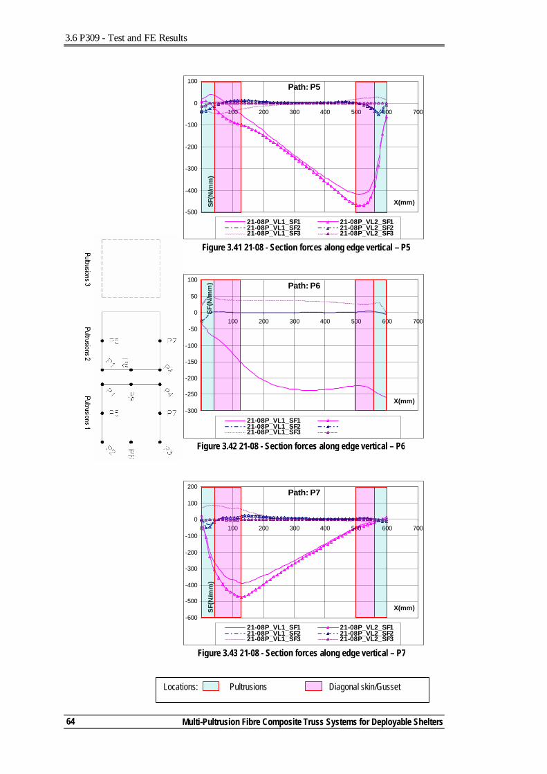
3.6 P309 - Test and FE Results
Multi-Pultrusion Fibre Composite Truss Systems for Deployable Shelters
64
Path: P5
-500
-400
-300
-200
-100
0
100
0 100 200 300 400 500 600 700
X(mm)SF(N
/mm
)
21-08P_VL1_SF1 21-08P_VL2_SF121-08P_VL1_SF2 21-08P_VL2_SF221-08P_VL1_SF3 21-08P_VL2_SF3
Figure 3.41 21-08 - Section forces along edge vertical – P5
Path: P7
-600
-500
-400
-300
-200
-100
0
100
200
0 100 200 300 400 500 600 700
X(mm)SF(N
/mm
)
21-08P_VL1_SF1 21-08P_VL2_SF121-08P_VL1_SF2 21-08P_VL2_SF221-08P_VL1_SF3 21-08P_VL2_SF3
Figure 3.43 21-08 - Section forces along edge vertical – P7
Path: P6
-300
-250
-200
-150
-100
-50
0
50
100
0 100 200 300 400 500 600 700
X(mm)
SF(N
/mm
)
21-08P_VL1_SF121-08P_VL1_SF221-08P_VL1_SF3
Figure 3.42 21-08 - Section forces along edge vertical – P6
Locations: Pultrusions Diagonal skin/Gusset
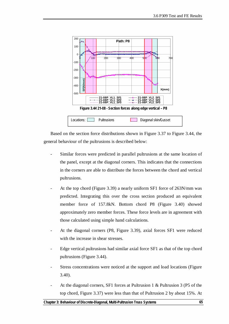
3.6 P309 Test and FE Results
Chapter 3: Behaviour of Discrete-Diagonal, Multi-Pultrusion Truss Systems
65
Based on the section force distributions shown in Figure 3.37 to Figure 3.44, the
general behaviour of the pultrusions is described below:
- Similar forces were predicted in parallel pultrusions at the same location of
the panel, except at the diagonal corners. This indicates that the connections
in the corners are able to distribute the forces between the chord and vertical
pultrusions.
- At the top chord (Figure 3.39) a nearly uniform SF1 force of 263N/mm was
predicted. Integrating this over the cross section produced an equivalent
member force of 157.8kN. Bottom chord P8 (Figure 3.40) showed
approximately zero member forces. These force levels are in agreement with
those calculated using simple hand calculations.
- At the diagonal corners (P8, Figure 3.39), axial forces SF1 were reduced
with the increase in shear stresses.
- Edge vertical pultrusions had similar axial force SF1 as that of the top chord
pultrusions (Figure 3.44).
- Stress concentrations were noticed at the support and load locations (Figure
3.40).
- At the diagonal corners, SF1 forces at Pultrusion 1 & Pultrusion 3 (P5 of the
top chord, Figure 3.37) were less than that of Pultrusion 2 by about 15%. At
Locations: Pultrusions Diagonal skin/Gusset
Path: P8
-500
-400
-300
-200
-100
0
100
200
0 100 200 300 400 500 600 700
X(mm)SF(N
/mm
)
21-08P_VL1_SF1 21-08P_VL2_SF121-08P_VL1_SF2 21-08P_VL2_SF221-08P_VL1_SF3 21-08P_VL2_SF3
Figure 3.44 21-08 - Section forces along edge vertical – P8
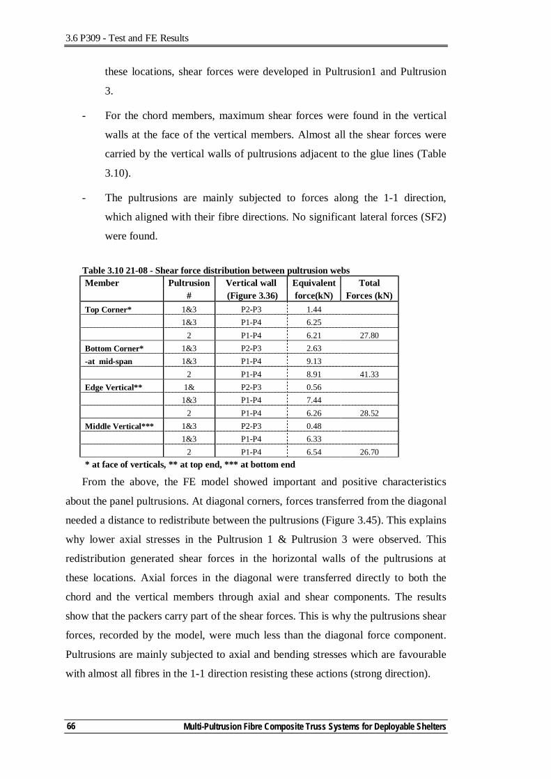
3.6 P309 - Test and FE Results
Multi-Pultrusion Fibre Composite Truss Systems for Deployable Shelters
66
these locations, shear forces were developed in Pultrusion1 and Pultrusion
3.
- For the chord members, maximum shear forces were found in the vertical
walls at the face of the vertical members. Almost all the shear forces were
carried by the vertical walls of pultrusions adjacent to the glue lines (Table
3.10).
- The pultrusions are mainly subjected to forces along the 1-1 direction,
which aligned with their fibre directions. No significant lateral forces (SF2)
were found.
Table 3.10 21-08 - Shear force distribution between pultrusion webs Member Pultrusion Vertical wall Equivalent Total # (Figure 3.36) force(kN) Forces (kN) Top Corner* 1&3 P2-P3 1.44 1&3 P1-P4 6.25 2 P1-P4 6.21 27.80 Bottom Corner* 1&3 P2-P3 2.63 -at mid-span 1&3 P1-P4 9.13 2 P1-P4 8.91 41.33 Edge Vertical** 1& P2-P3 0.56 1&3 P1-P4 7.44 2 P1-P4 6.26 28.52 Middle Vertical*** 1&3 P2-P3 0.48 1&3 P1-P4 6.33 2 P1-P4 6.54 26.70 * at face of verticals, ** at top end, *** at bottom end
From the above, the FE model showed important and positive characteristics
about the panel pultrusions. At diagonal corners, forces transferred from the diagonal
needed a distance to redistribute between the pultrusions (Figure 3.45). This explains
why lower axial stresses in the Pultrusion 1 & Pultrusion 3 were observed. This
redistribution generated shear forces in the horizontal walls of the pultrusions at
these locations. Axial forces in the diagonal were transferred directly to both the
chord and the vertical members through axial and shear components. The results
show that the packers carry part of the shear forces. This is why the pultrusions shear
forces, recorded by the model, were much less than the diagonal force component.
Pultrusions are mainly subjected to axial and bending stresses which are favourable
with almost all fibres in the 1-1 direction resisting these actions (strong direction).
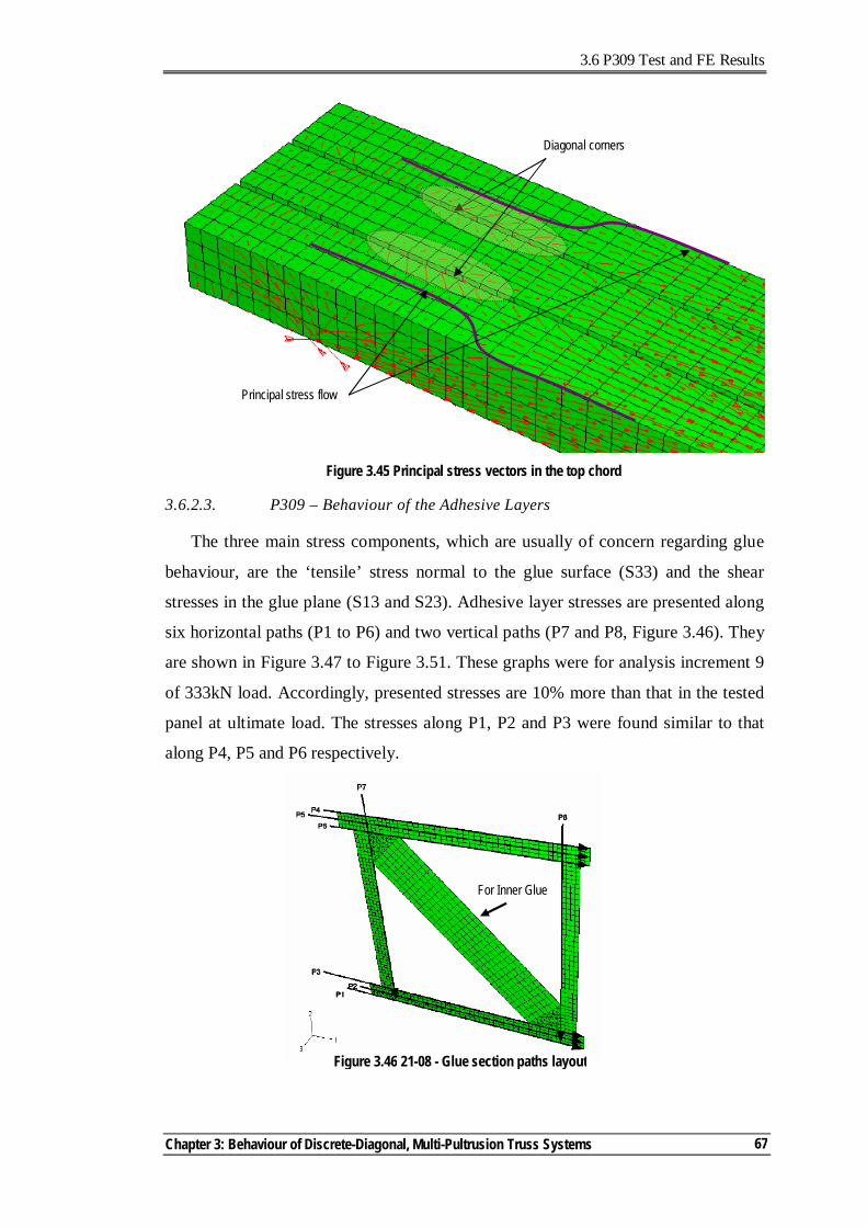
3.6 P309 Test and FE Results
Chapter 3: Behaviour of Discrete-Diagonal, Multi-Pultrusion Truss Systems
67
3.6.2.3. P309 – Behaviour of the Adhesive Layers
The three main stress components, which are usually of concern regarding glue
behaviour, are the ‘tensile’ stress normal to the glue surface (S33) and the shear
stresses in the glue plane (S13 and S23). Adhesive layer stresses are presented along
six horizontal paths (P1 to P6) and two vertical paths (P7 and P8, Figure 3.46). They
are shown in Figure 3.47 to Figure 3.51. These graphs were for analysis increment 9
of 333kN load. Accordingly, presented stresses are 10% more than that in the tested
panel at ultimate load. The stresses along P1, P2 and P3 were found similar to that
along P4, P5 and P6 respectively.
Diagonal corners
Principal stress flow
Figure 3.45 Principal stress vectors in the top chord
Figure 3.46 21-08 - Glue section paths layout
For Inner Glue
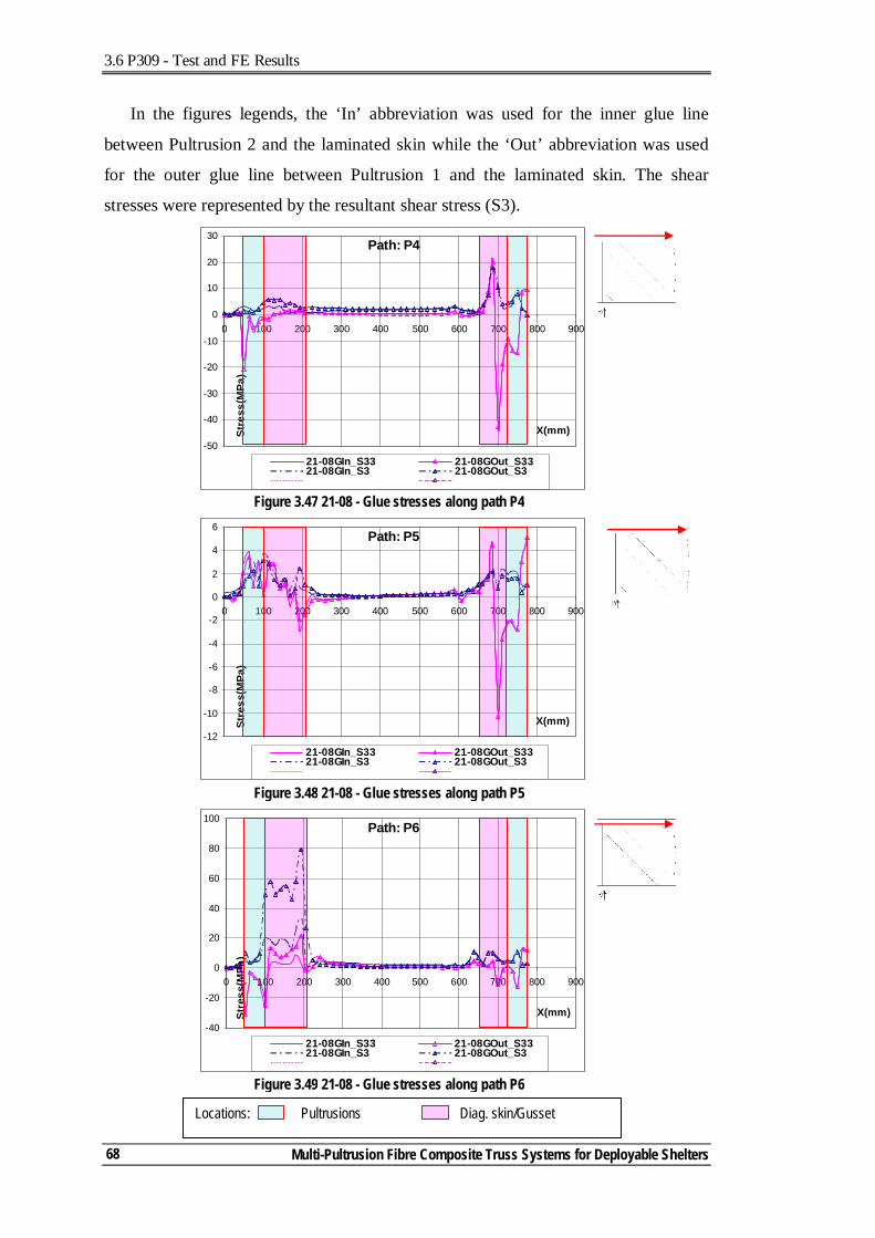
3.6 P309 - Test and FE Results
Multi-Pultrusion Fibre Composite Truss Systems for Deployable Shelters
68
In the figures legends, the ‘In’ abbreviation was used for the inner glue line
between Pultrusion 2 and the laminated skin while the ‘Out’ abbreviation was used
for the outer glue line between Pultrusion 1 and the laminated skin. The shear
stresses were represented by the resultant shear stress (S3).
Locations: Pultrusions Diag. skin/Gusset
Figure 3.47 21-08 - Glue stresses along path P4
Path: P4
-50
-40
-30
-20
-10
0
10
20
30
0 100 200 300 400 500 600 700 800 900
X(mm)Stre
ss(M
Pa)
21-08GIn_S33 21-08GOut_S3321-08GIn_S3 21-08GOut_S3
Figure 3.49 21-08 - Glue stresses along path P6
Path: P6
-40
-20
0
20
40
60
80
100
0 100 200 300 400 500 600 700 800 900
X(mm)Stre
ss(M
Pa)
21-08GIn_S33 21-08GOut_S3321-08GIn_S3 21-08GOut_S3
Figure 3.48 21-08 - Glue stresses along path P5
Path: P5
-12
-10
-8
-6
-4
-2
0
2
4
6
0 100 200 300 400 500 600 700 800 900
X(mm)Stre
ss(M
Pa)
21-08GIn_S33 21-08GOut_S3321-08GIn_S3 21-08GOut_S3
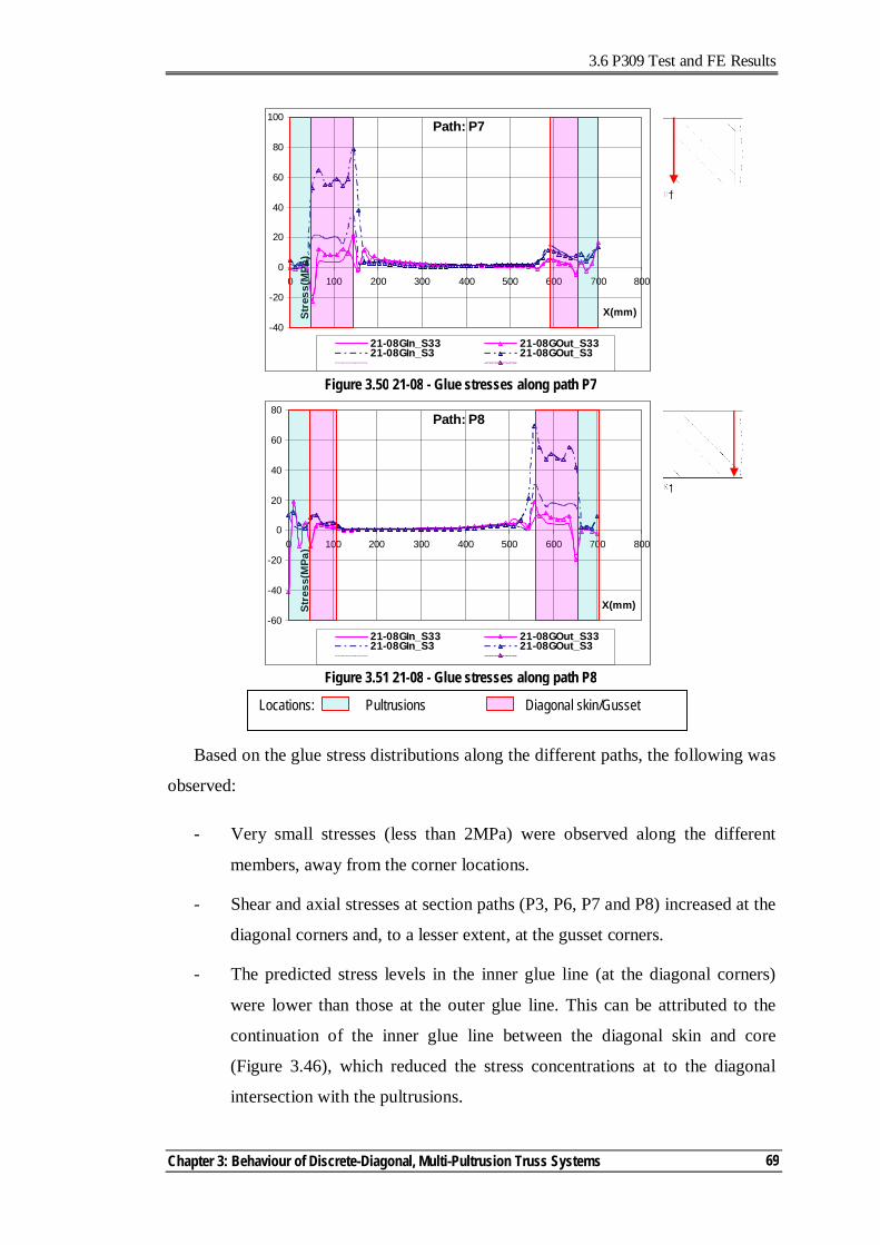
3.6 P309 Test and FE Results
Chapter 3: Behaviour of Discrete-Diagonal, Multi-Pultrusion Truss Systems
69
Based on the glue stress distributions along the different paths, the following was
observed:
- Very small stresses (less than 2MPa) were observed along the different
members, away from the corner locations.
- Shear and axial stresses at section paths (P3, P6, P7 and P8) increased at the
diagonal corners and, to a lesser extent, at the gusset corners.
- The predicted stress levels in the inner glue line (at the diagonal corners)
were lower than those at the outer glue line. This can be attributed to the
continuation of the inner glue line between the diagonal skin and core
(Figure 3.46), which reduced the stress concentrations at to the diagonal
intersection with the pultrusions.
Locations: Pultrusions Diagonal skin/Gusset
Path: P7
-40
-20
0
20
40
60
80
100
0 100 200 300 400 500 600 700 800
X(mm)Stre
ss(M
Pa)
21-08GIn_S33 21-08GOut_S3321-08GIn_S3 21-08GOut_S3
Figure 3.50 21-08 - Glue stresses along path P7
Path: P8
-60
-40
-20
0
20
40
60
80
0 100 200 300 400 500 600 700 800
X(mm)Stre
ss(M
Pa)
21-08GIn_S33 21-08GOut_S3321-08GIn_S3 21-08GOut_S3
Figure 3.51 21-08 - Glue stresses along path P8
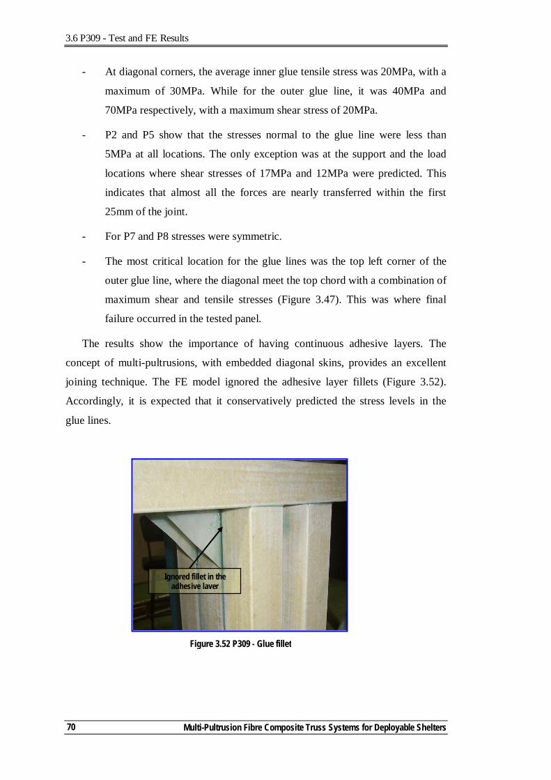
3.6 P309 - Test and FE Results
Multi-Pultrusion Fibre Composite Truss Systems for Deployable Shelters
70
- At diagonal corners, the average inner glue tensile stress was 20MPa, with a
maximum of 30MPa. While for the outer glue line, it was 40MPa and
70MPa respectively, with a maximum shear stress of 20MPa.
- P2 and P5 show that the stresses normal to the glue line were less than
5MPa at all locations. The only exception was at the support and the load
locations where shear stresses of 17MPa and 12MPa were predicted. This
indicates that almost all the forces are nearly transferred within the first
25mm of the joint.
- For P7 and P8 stresses were symmetric.
- The most critical location for the glue lines was the top left corner of the
outer glue line, where the diagonal meet the top chord with a combination of
maximum shear and tensile stresses (Figure 3.47). This was where final
failure occurred in the tested panel.
The results show the importance of having continuous adhesive layers. The
concept of multi-pultrusions, with embedded diagonal skins, provides an excellent
joining technique. The FE model ignored the adhesive layer fillets (Figure 3.52).
Accordingly, it is expected that it conservatively predicted the stress levels in the
glue lines.
Ignored fillet in the adhesive layer
Figure 3.52 P309 - Glue fillet
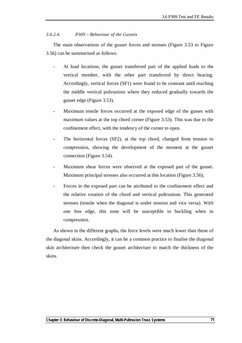
3.6 P309 Test and FE Results
Chapter 3: Behaviour of Discrete-Diagonal, Multi-Pultrusion Truss Systems
71
3.6.2.4. P309 – Behaviour of the Gussets
The main observations of the gusset forces and stresses (Figure 3.53 to Figure
3.56) can be summarised as follows:
- At load locations, the gusset transferred part of the applied loads to the
vertical member, with the other part transferred by direct bearing.
Accordingly, vertical forces (SF1) were found to be constant until reaching
the middle vertical pultrusions where they reduced gradually towards the
gusset edge (Figure 3.53).
- Maximum tensile forces occurred at the exposed edge of the gusset with
maximum values at the top chord corner (Figure 3.53). This was due to the
confinement effect, with the tendency of the corner to open.
- The horizontal forces (SF2), at the top chord, changed from tension to
compression, showing the development of the moment at the gusset
connection (Figure 3.54).
- Maximum shear forces were observed at the exposed part of the gusset.
Maximum principal stresses also occurred at this location (Figure 3.56);
- Forces in the exposed part can be attributed to the confinement effect and
the relative rotation of the chord and vertical pultrusions. This generated
stresses (tensile when the diagonal is under tension and vice versa). With
one free edge, this zone will be susceptible to buckling when in
compression.
As shown in the different graphs, the force levels were much lower than those of
the diagonal skins. Accordingly, it can be a common practice to finalise the diagonal
skin architecture then check the gusset architecture to match the thickness of the
skins.
3.6 P309 - Test and FE Results
Multi-Pultrusion Fibre Composite Truss Systems for Deployable Shelters
72
Figure 3.53 21-08 - Gusset section forces SF1 (vertical)
Figure 3.54 21-08 - Gusset axial section forces SF2 (horizontal)
Figure 3.55 21-08 - Gusset shear section forces SF3
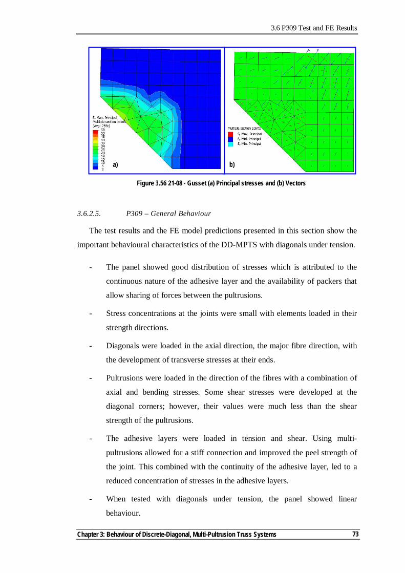
3.6 P309 Test and FE Results
Chapter 3: Behaviour of Discrete-Diagonal, Multi-Pultrusion Truss Systems
73
3.6.2.5. P309 – General Behaviour
The test results and the FE model predictions presented in this section show the
important behavioural characteristics of the DD-MPTS with diagonals under tension.
- The panel showed good distribution of stresses which is attributed to the
continuous nature of the adhesive layer and the availability of packers that
allow sharing of forces between the pultrusions.
- Stress concentrations at the joints were small with elements loaded in their
strength directions.
- Diagonals were loaded in the axial direction, the major fibre direction, with
the development of transverse stresses at their ends.
- Pultrusions were loaded in the direction of the fibres with a combination of
axial and bending stresses. Some shear stresses were developed at the
diagonal corners; however, their values were much less than the shear
strength of the pultrusions.
- The adhesive layers were loaded in tension and shear. Using multi-
pultrusions allowed for a stiff connection and improved the peel strength of
the joint. This combined with the continuity of the adhesive layer, led to a
reduced concentration of stresses in the adhesive layers.
- When tested with diagonals under tension, the panel showed linear
behaviour.
Figure 3.56 21-08 - Gusset (a) Principal stresses and (b) Vectors
a) b)
3.6 P309 - Test and FE Results
Multi-Pultrusion Fibre Composite Truss Systems for Deployable Shelters
74
- Other behavioural issues of buckling of the diagonals and any effects of
imperfection in setting the panel need to be assessed. These issues are
discussed in Chapter 4.
- The packers played important role by redistributing the forces between the
three pultrusions ensuring their composite actions and carrying part of the
shear forces at the diagonal joint location.
- Compared to the joint efficiency of the bracket P209, Sec. 3.3.3 p38, the
failure occurred in the diagonal member not at the joint, 100% joint
efficiency. However, due to the confinement of the diagonal at its ends, the
member capacity was reduced when compared to the uni-directional
stressed member. Comparing the force in the diagonals at ultimate load
(210kN) to the equivalent of the uni-axially loaded skins (239kN) reveals
that the overall member efficiency is 87% which is much higher than the
joint capacity of P209 (42%).
- In correlating the load capacity of the panel to the strain level in the
diagonal, as a measure of the level of stress at ultimate load, P309 in tension
reached 26.6N/microstrain.
3.7. CONCLUSIONS
This chapter presented the investigations conducted for the discrete diagonal
truss systems. The first panel to be manufactured was adhesively bonded composite
sections cast in PFR. The panel was not tested due to many shortcomings which
include a complicated manufacturing process, lack of any redundancy in the system,
and the increased weight due to the PFR.
Based on the exercise of constructing the first panel, the main considerations for
future panel developments were established. Subsequently, the discrete-diagonal,
multi-pultrusion truss-system (DD-MPTS) was developed. The concept was refined
by eliminating the use of gussets by using diagonals of sandwich construction with
skins embedded between the chord and vertical pultrusions. This allowed direct
transfer of forces, and, accordingly, achieved high load carrying capacity.
3.7 Conclusions
Chapter 3: Behaviour of Discrete-Diagonal, Multi-Pultrusion Truss Systems
75
The first DD-MPTS prototype panel to be tested has diagonals under tension - the
most critical loading condition for the joints. The panel structural performance was
outstanding with failure occurring in the diagonal skins. The good characteristics of
this system include (i) its high load carrying capacity, (ii) desirable failure modes
with no sudden complete failure, (iii) alternate load paths, (iv) predictable failure
mode, and (iv) ease of manufacturing.
The FE results developed to simulate the panel test showed an excellent
correlation with the test results. The FE results were used to derive an understanding
of the main characteristics of the panel system. The good performance of the test
panel was attributed to its structural system which allowed each of its components to
be loaded in its strength direction.
A characteristic of this system was the confinement effect due to the finite
dimension of the diagonal at corners and the tendency of other members to rotate
relative to each other. As failure originated and propagated in the diagonals, the
behaviour of the panel with diagonals under compression will be more complicated.
In Chapter 4, the DD-MPTS concept will be investigated further by researching
the behaviour of DD-MPTS panel with sandwich diagonals subjected to compressive
forces.
3.8 References
Multi-Pultrusion Fibre Composite Truss Systems for Deployable Shelters
76
3.8. REFERENCES
Akfert, A. (1994). Finite element analysis of composite sandwich beams and plates, MSc, University of Manchester, Manchester.
ATL Composites Homepage. http://www.atlcomposites.com.au. Bazant, Z. P., and Beghini, A. (2004). Sandwich buckling formulas and applicability
of standard computational algorithm for finite strain. Composites Pt B, 35, 573-581.
Clarke, J. L. (1996). Structural design of polymer composites - Eurocomp. E & FN Spon, London.
Colan Homepage. http://www.colan.com.au. Diab Homepage. http://www.diabgroup.com.
Gibson, L. J., Ashby, M. F., Schajer, G. S., and Robertson, C. I. (1982). The mechanics of two-dimensional cellular materials. Proceedings of the Royal Society, London, 25–42.
Gibson, L. J., and Ashby, M. F. (1997). Cellular solids: structure & properties, Cambridge University Press, Cambridge.
Haug, A., and Jamjian, M. (1996). Numerical simulation of the impact resistance of composite structures. Numerical analysis and modelling of composite materials, J. W. Bull, ed., Blackie Academic, London, 185-244.
Hibbitt, Karlsson & Sorensen Inc. (2004a). ABAQUS Analysis user's manual, Pawtucket, USA.
Hibbitt, Karlsson & Sorensen Inc. (2004b). ABAQUS Theory manual, Pawtucket, USA.
Lavender Composites Homepage. www.lavender-ce.com. Maiti, S. K., Gibson, L. J., and Ashby, M. F. (1984). Deformation and energy
absorption diagrams for cellular solids. Acta Metallurgica, 32(11), 1963–1975.
Muc, A., and Zuchara, P. (2000). Buckling and failure analysis of FRP faced sandwich plates. Composite Structures, 48, 145-150.
Omar, T. (2000). Behaviour of concrete-filled-steel-tube members in flexure, ME, University of Auckland, Auckland, New Zealand.
Pacific Composites Homepage. http://www.pacomp.com.au/. Pagano, N. J. (1970). Exact solutions for rectangular bidirectional composites and
sandwich plates. J of Composite Materials, 4, 20-34.
Rogers, D. (2004). Characterisation of Hyrez 201 laminating resin. Polymer Testing Laboratory, University of Southern Queensland, Toowoomba, Queensland.
Tsai, S. W. (1991). Composite Design, Think Composites, Dayton, Ohio.
Chapter 3: Behaviour of Discrete-Diagonal, Multi-Pultrusion Truss Systems
77
Vannucci, P., Aivazzadeh, S., and Verchery, G. (1998). A comparative analysis of some theories and finite elements for sandwich plates and shells. Mechanics of sandwich structures, A. Vautrin, ed., Kluwer Academic Publishers, Saint-Etienne, 45-52.
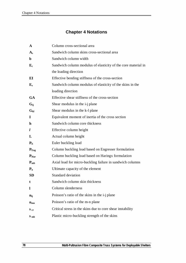
Chapter 4 Notations
Multi-Pultrusion Fibre Composite Truss Systems for Deployable Shelters
78
Chapter 4 Notations
A Column cross-sectional area
As Sandwich column skins cross-sectional area
b Sandwich column width
Ec Sandwich column modulus of elasticity of the core material in
the loading direction
EI Effective bending stiffness of the cross-section
Es Sandwich column modulus of elasticity of the skins in the
loading direction
GA Effective shear stiffness of the cross-section
Gij Shear modulus in the i-j plane
Gkl Shear modulus in the k-l plane
I Equivalent moment of inertia of the cross section
h Sandwich column core thickness
l Effective column height
L Actual column height
PE Euler buckling load
PEng Column buckling load based on Engresser formulation
PHar Column buckling load based on Haringx formulation
Pmb Axial load for micro-buckling failure in sandwich columns
Pu Ultimate capacity of the element
SD Standard deviation
t Sandwich column skin thickness
λ Column slenderness
νij Poisson’s ratio of the skins in the i-j plane
νmn Poisson’s ratio of the m-n plane
σcr Critical stress in the skins due to core shear instability
σmb Plastic micro-buckling strength of the skins
4.1 General
Chapter 4: Behaviour of Sandwich Members under Axial Loads – Application for DD-MPTS
79
4. Behaviour of Sandwich Members under Axial Loads –
Application for Discrete-Diagonal Multi-Pultrusion Truss Systems
4.1. GENERAL
The multi-pultrusion truss system (DD-MPTS) panel, with diagonals under
tension, showed excellent structural behaviour as detailed in Chapter 3. In real life
situations, diagonals will be subjected to both tension and compression, due to load
fluctuation or their location in the structure. Accordingly, it was necessary to
investigate the DD-MPTS with diagonals under compression. Using sandwich
construction for the diagonals provided many advantages to the concept of DD-
MPTS (Sec.3.3, p33). However, with sandwich diagonal under compression, other
factors such as transverse shear modulus of the core material, skin architecture and
end restraints can significantly affect its ultimate capacity and failure mode. The
other important specific issue regarding DD-MPTS is the bi-axial stress status at the
diagonal ends, transverse tensile stresses combined with longitudinal compressive
stresses. All these issues need to be addressed in investigating the DD-MPTS with
diagonals under compression.
In this chapter, the behaviour of sandwich columns, under edge-wise
compression, is investigated to form the bases for investigating the behaviour of DD-
MPTS with diagonals under compression. With the understanding of the behaviour
of the prototype sandwich columns, informed decisions can be made for the DD-
MPTS. Preliminary investigations were conducted for a limited number of column
specimens with different core materials. These investigations showed the
significance of the core material on the column capacity and failure mode.
4.1 General
Multi-Pultrusion Fibre Composite Truss Systems for Deployable Shelters
80
The literature review relevant to this chapter provides an overview of the
different applications of sandwich structure, confirming that their use in civil
engineering applications has been limited. In addition, the literature review enabled
identification of the behavioural issues relevant to sandwich columns and
mathematical expressions to predict their capacities. Single-core columns are
commonly used in sandwich columns. No reference was located that referred to
mixed-core column behaviour.
A total of six sets of columns were tested under compression. They had similar
skin fibre architecture with three different arrangements of core materials: low-
density closed-cell PVC foam, high-density balsa1 and a combination of the low-
density foam and balsa (mixed-core).
To keep the panel simple so effort could be directed towards developing a basic
understanding of its behaviour, single-core sandwich diagonals were used in the DD-
MPTS panel. Detailed analysis of the test results for the single-core columns is
presented in this chapter. However, mixed-cores were included in the column tests as
material availability, weight optimisation, cost, failure and post-failure structural
behaviour are good reasons for considering their use. The test results for the mixed-
core sandwich columns are presented in Appendix C for interested researchers who
may wish to pursue the concept.
The FE model, presented in Chapter 3, successfully predicted the DD-MPTS
behaviour with diagonals under tension. FE modelling procedures similar to those
used with DD-MPTS diagonals were followed to model the sandwich columns, with
slight modification to predict their buckling behaviour. In verifying the FE model
with the test results, simplified FE modelling procedures are presented and compared
to the more detailed model. This provided the base to develop simplified models at
the macro-level analysis as detailed in Chapter 6. Sandwich column design equations
found in the literature were verified using the FE models.
With knowledge gained in investigating sandwich columns, a full-height DD-
MPTS panel was tested with diagonals under compression. The test results
1 Originally, it was planned to use high-density closed-cell PVC foam. However, being unavailable for a few months, end-grain balsa was used as a high shear modulus alternative.
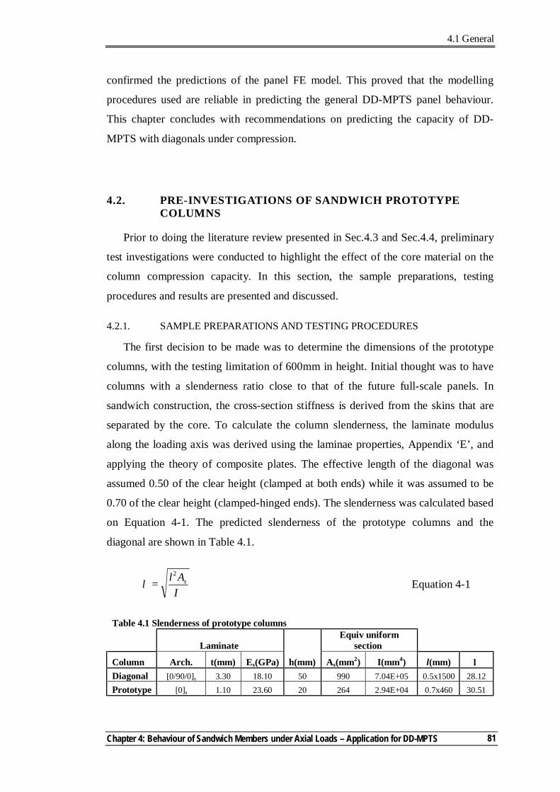
4.1 General
Chapter 4: Behaviour of Sandwich Members under Axial Loads – Application for DD-MPTS
81
confirmed the predictions of the panel FE model. This proved that the modelling
procedures used are reliable in predicting the general DD-MPTS panel behaviour.
This chapter concludes with recommendations on predicting the capacity of DD-
MPTS with diagonals under compression.
4.2. PRE-INVESTIGATIONS OF SANDWICH PROTOTYPE COLUMNS
Prior to doing the literature review presented in Sec.4.3 and Sec.4.4, preliminary
test investigations were conducted to highlight the effect of the core material on the
column compression capacity. In this section, the sample preparations, testing
procedures and results are presented and discussed.
4.2.1. SAMPLE PREPARATIONS AND TESTING PROCEDURES
The first decision to be made was to determine the dimensions of the prototype
columns, with the testing limitation of 600mm in height. Initial thought was to have
columns with a slenderness ratio close to that of the future full-scale panels. In
sandwich construction, the cross-section stiffness is derived from the skins that are
separated by the core. To calculate the column slenderness, the laminate modulus
along the loading axis was derived using the laminae properties, Appendix ‘E’, and
applying the theory of composite plates. The effective length of the diagonal was
assumed 0.50 of the clear height (clamped at both ends) while it was assumed to be
0.70 of the clear height (clamped-hinged ends). The slenderness was calculated based
on Equation 4-1. The predicted slenderness of the prototype columns and the
diagonal are shown in Table 4.1.
IAl s
2
=λ Equation 4-1
Table 4.1 Slenderness of prototype columns
Laminate Equiv uniform
section
Column Arch. t(mm) Es(GPa) h(mm) As(mm2) I(mm4) l(mm) λ Diagonal [0/90/0]s 3.30 18.10 50 990 7.04E+05 0.5x1500 28.12 Prototype [0]s 1.10 23.60 20 264 2.94E+04 0.7x460 30.51
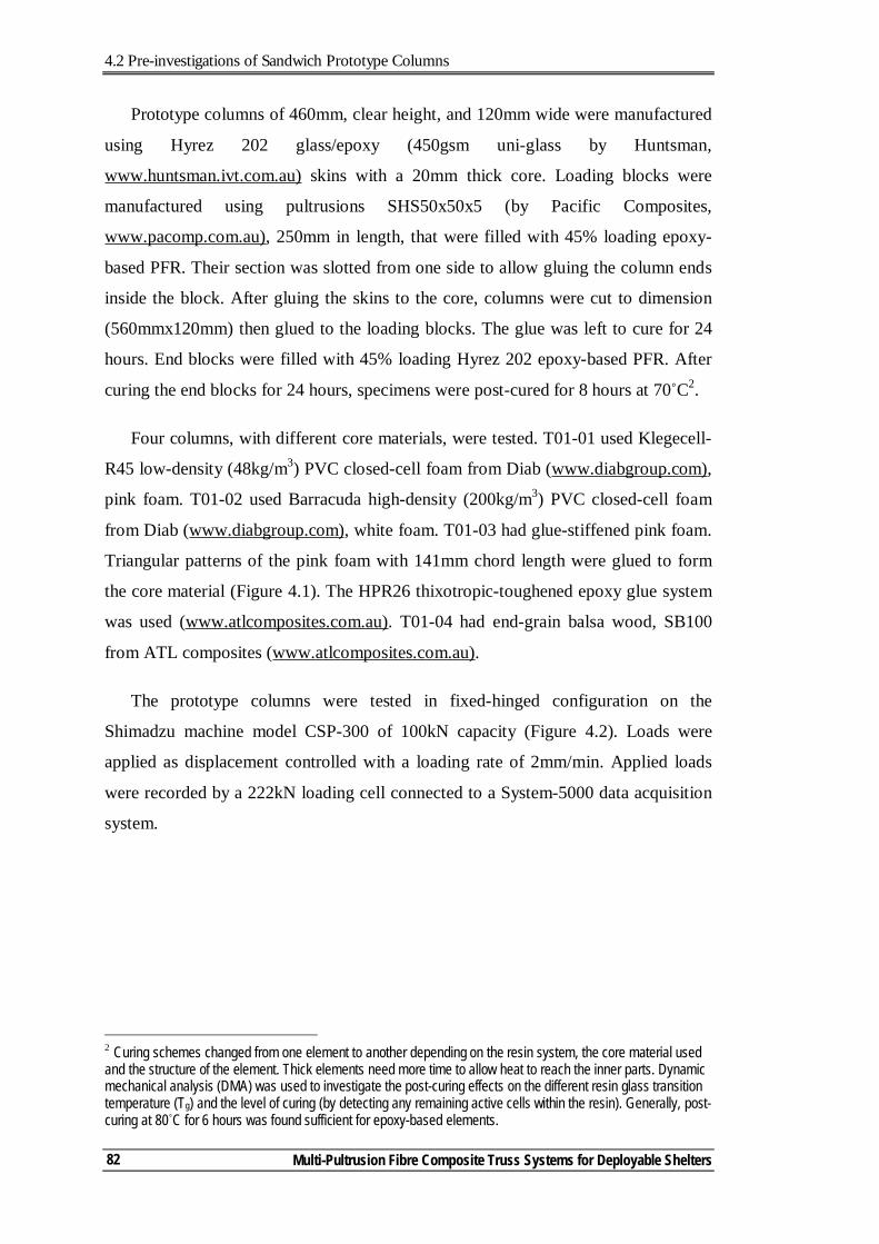
4.2 Pre-investigations of Sandwich Prototype Columns
Multi-Pultrusion Fibre Composite Truss Systems for Deployable Shelters
82
Prototype columns of 460mm, clear height, and 120mm wide were manufactured
using Hyrez 202 glass/epoxy (450gsm uni-glass by Huntsman,
www.huntsman.ivt.com.au) skins with a 20mm thick core. Loading blocks were
manufactured using pultrusions SHS50x50x5 (by Pacific Composites,
www.pacomp.com.au), 250mm in length, that were filled with 45% loading epoxy-
based PFR. Their section was slotted from one side to allow gluing the column ends
inside the block. After gluing the skins to the core, columns were cut to dimension
(560mmx120mm) then glued to the loading blocks. The glue was left to cure for 24
hours. End blocks were filled with 45% loading Hyrez 202 epoxy-based PFR. After
curing the end blocks for 24 hours, specimens were post-cured for 8 hours at 70˚C2.
Four columns, with different core materials, were tested. T01-01 used Klegecell-
R45 low-density (48kg/m3) PVC closed-cell foam from Diab (www.diabgroup.com),
pink foam. T01-02 used Barracuda high-density (200kg/m3) PVC closed-cell foam
from Diab (www.diabgroup.com), white foam. T01-03 had glue-stiffened pink foam.
Triangular patterns of the pink foam with 141mm chord length were glued to form
the core material (Figure 4.1). The HPR26 thixotropic-toughened epoxy glue system
was used (www.atlcomposites.com.au). T01-04 had end-grain balsa wood, SB100
from ATL composites (www.atlcomposites.com.au).
The prototype columns were tested in fixed-hinged configuration on the
Shimadzu machine model CSP-300 of 100kN capacity (Figure 4.2). Loads were
applied as displacement controlled with a loading rate of 2mm/min. Applied loads
were recorded by a 222kN loading cell connected to a System-5000 data acquisition
system.
2 Curing schemes changed from one element to another depending on the resin system, the core material used and the structure of the element. Thick elements need more time to allow heat to reach the inner parts. Dynamic mechanical analysis (DMA) was used to investigate the post-curing effects on the different resin glass transition temperature (Tg) and the level of curing (by detecting any remaining active cells within the resin). Generally, post-curing at 80˚C for 6 hours was found sufficient for epoxy-based elements.
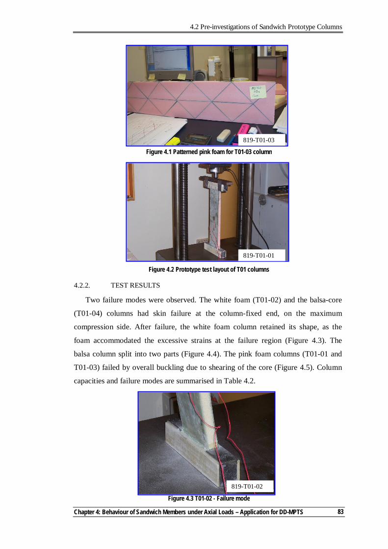
4.2 Pre-investigations of Sandwich Prototype Columns
Chapter 4: Behaviour of Sandwich Members under Axial Loads – Application for DD-MPTS
83
4.2.2. TEST RESULTS
Two failure modes were observed. The white foam (T01-02) and the balsa-core
(T01-04) columns had skin failure at the column-fixed end, on the maximum
compression side. After failure, the white foam column retained its shape, as the
foam accommodated the excessive strains at the failure region (Figure 4.3). The
balsa column split into two parts (Figure 4.4). The pink foam columns (T01-01 and
T01-03) failed by overall buckling due to shearing of the core (Figure 4.5). Column
capacities and failure modes are summarised in Table 4.2.
Figure 4.3 T01-02 - Failure mode
Figure 4.1 Patterned pink foam for T01-03 column
819-T01-03
Figure 4.2 Prototype test layout of T01 columns
819-T01-01
819-T01-02
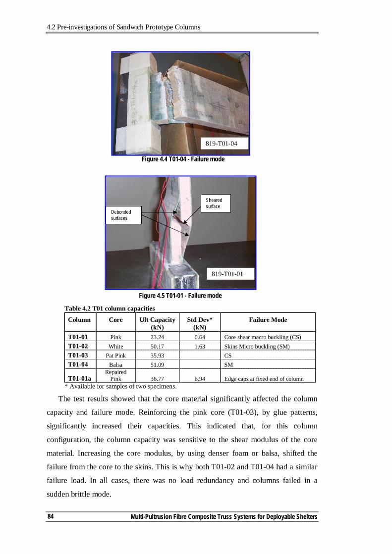
4.2 Pre-investigations of Sandwich Prototype Columns
Multi-Pultrusion Fibre Composite Truss Systems for Deployable Shelters
84
Table 4.2 T01 column capacities
Column
Core
Ult Capacity (kN)
Std Dev* (kN)
Failure Mode
T01-01 Pink 23.24 0.64 Core shear macro buckling (CS) T01-02 White 50.17 1.63 Skins Micro buckling (SM) T01-03 Pat Pink 35.93 CS T01-04 Balsa 51.09 SM
T01-01a Repaired
Pink 36.77 6.94 Edge caps at fixed end of column * Available for samples of two specimens.
The test results showed that the core material significantly affected the column
capacity and failure mode. Reinforcing the pink core (T01-03), by glue patterns,
significantly increased their capacities. This indicated that, for this column
configuration, the column capacity was sensitive to the shear modulus of the core
material. Increasing the core modulus, by using denser foam or balsa, shifted the
failure from the core to the skins. This is why both T01-02 and T01-04 had a similar
failure load. In all cases, there was no load redundancy and columns failed in a
sudden brittle mode.
Figure 4.4 T01-04 - Failure mode
819-T01-04
Figure 4.5 T01-01 - Failure mode
Debonded surfaces
Sheared surface
819-T01-01
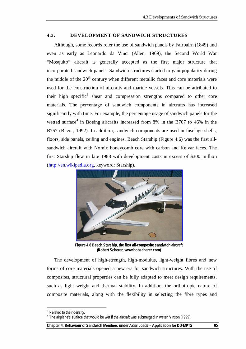
4.3 Developments of Sandwich Structures
Chapter 4: Behaviour of Sandwich Members under Axial Loads – Application for DD-MPTS
85
4.3. DEVELOPMENT OF SANDWICH STRUCTURES
Although, some records refer the use of sandwich panels by Fairbairn (1849) and
even as early as Leonardo da Vinci (Allen, 1969), the Second World War
“Mosquito” aircraft is generally accepted as the first major structure that
incorporated sandwich panels. Sandwich structures started to gain popularity during
the middle of the 20th century when different metallic faces and core materials were
used for the construction of aircrafts and marine vessels. This can be attributed to
their high specific3 shear and compression strengths compared to other core
materials. The percentage of sandwich components in aircrafts has increased
significantly with time. For example, the percentage usage of sandwich panels for the
wetted surface4 in Boeing aircrafts increased from 8% in the B707 to 46% in the
B757 (Bitzer, 1992). In addition, sandwich components are used in fuselage shells,
floors, side panels, ceiling and engines. Beech Starship (Figure 4.6) was the first all-
sandwich aircraft with Nomix honeycomb core with carbon and Kelvar faces. The
first Starship flew in late 1988 with development costs in excess of $300 million
(http://en.wikipedia.org, keyword: Starship).
The development of high-strength, high-modulus, light-weight fibres and new
forms of core materials opened a new era for sandwich structures. With the use of
composites, structural properties can be fully adapted to meet design requirements,
such as light weight and thermal stability. In addition, the orthotropic nature of
composite materials, along with the flexibility in selecting the fibre types and
3 Related to their density. 4 The airplane’s surface that would be wet if the aircraft was submerged in water, Vinson (1999).
Figure 4.6 Beech Starship, the first all-composite sandwich aircraft (Robert Scherer, www.bobscherer.com)
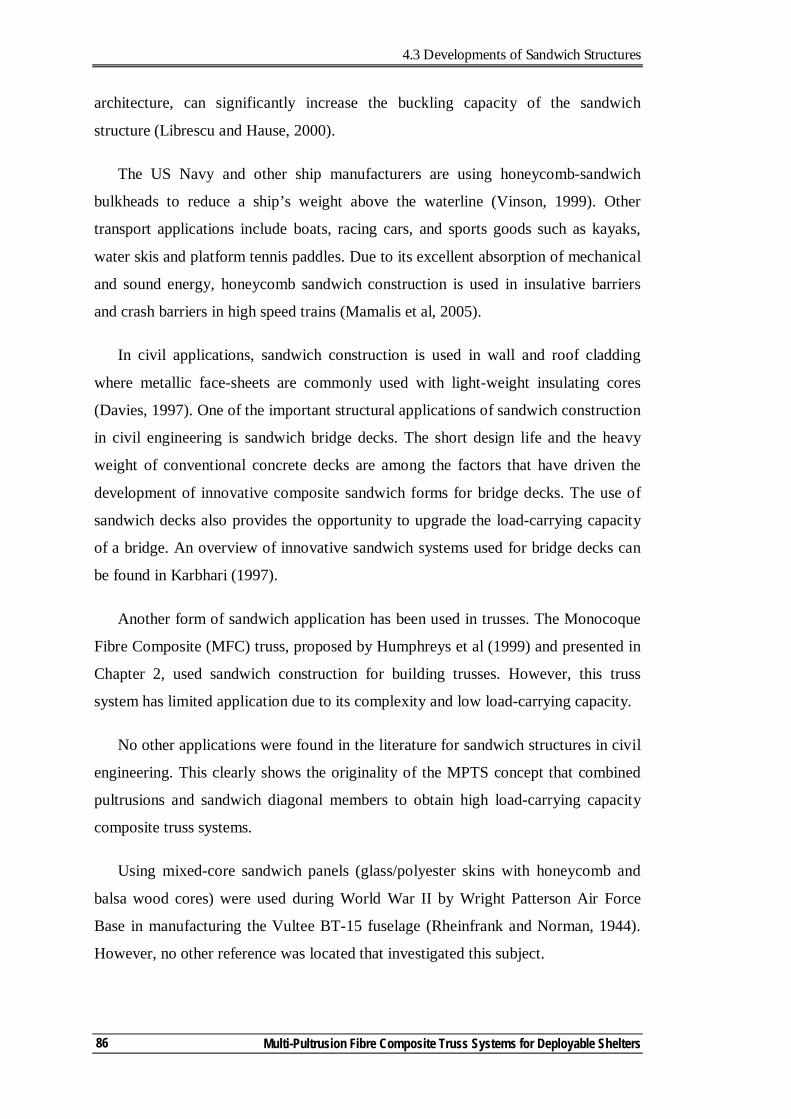
4.3 Developments of Sandwich Structures
Multi-Pultrusion Fibre Composite Truss Systems for Deployable Shelters
86
architecture, can significantly increase the buckling capacity of the sandwich
structure (Librescu and Hause, 2000).
The US Navy and other ship manufacturers are using honeycomb-sandwich
bulkheads to reduce a ship’s weight above the waterline (Vinson, 1999). Other
transport applications include boats, racing cars, and sports goods such as kayaks,
water skis and platform tennis paddles. Due to its excellent absorption of mechanical
and sound energy, honeycomb sandwich construction is used in insulative barriers
and crash barriers in high speed trains (Mamalis et al, 2005).
In civil applications, sandwich construction is used in wall and roof cladding
where metallic face-sheets are commonly used with light-weight insulating cores
(Davies, 1997). One of the important structural applications of sandwich construction
in civil engineering is sandwich bridge decks. The short design life and the heavy
weight of conventional concrete decks are among the factors that have driven the
development of innovative composite sandwich forms for bridge decks. The use of
sandwich decks also provides the opportunity to upgrade the load-carrying capacity
of a bridge. An overview of innovative sandwich systems used for bridge decks can
be found in Karbhari (1997).
Another form of sandwich application has been used in trusses. The Monocoque
Fibre Composite (MFC) truss, proposed by Humphreys et al (1999) and presented in
Chapter 2, used sandwich construction for building trusses. However, this truss
system has limited application due to its complexity and low load-carrying capacity.
No other applications were found in the literature for sandwich structures in civil
engineering. This clearly shows the originality of the MPTS concept that combined
pultrusions and sandwich diagonal members to obtain high load-carrying capacity
composite truss systems.
Using mixed-core sandwich panels (glass/polyester skins with honeycomb and
balsa wood cores) were used during World War II by Wright Patterson Air Force
Base in manufacturing the Vultee BT-15 fuselage (Rheinfrank and Norman, 1944).
However, no other reference was located that investigated this subject.
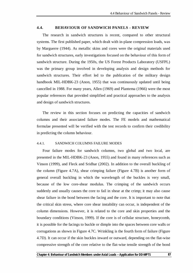
4.4 Behaviour of Sandwich Panels - Review
Chapter 4: Behaviour of Sandwich Members under Axial Loads – Application for DD-MPTS
87
4.4. BEHAVIOUR OF SANDWICH PANELS - REVIEW
The research in sandwich structures is recent, compared to other structural
systems. The first published paper, which dealt with in-plane compression loads, was
by Marguerre (1944). As metallic skins and cores were the original materials used
for sandwich structures, early investigations focused on the behaviour of this form of
sandwich structure. During the 1950s, the US Forest Products Laboratory (USFPL)
was the primary group involved in developing analysis and design methods for
sandwich structures. Their effort led to the publication of the military design
handbook MIL-HDBK-23 (Anon, 1955) that was continuously updated until being
cancelled in 1988. For many years, Allen (1969) and Plantema (1966) were the most
popular references that provided simplified and practical approaches to the analysis
and design of sandwich structures.
The review in this section focuses on predicting the capacities of sandwich
columns and their associated failure modes. The FE models and mathematical
formulae presented will be verified with the test records to confirm their credibility
in predicting the column behaviour.
4.4.1. SANDWICH COLUMNS FAILURE MODES
Four failure modes for sandwich columns, two global and two local, are
presented in the MIL-HDBK-23 (Anon, 1955) and found in many references such as
Vinson (1999), and Fleck and Sridhar (2002). In addition to the overall buckling of
the column (Figure 4.7A), shear crimping failure (Figure 4.7B) is another form of
general overall buckling in which the wavelength of the buckles is very small,
because of the low core-shear modulus. The crimping of the sandwich occurs
suddenly and usually causes the core to fail in shear at the crimp; it may also cause
shear failure in the bond between the facing and the core. It is important to note that
the critical skin stress, where core shear instability can occur, is independent of the
column dimensions. However, it is related to the core and skin properties and the
boundary conditions (Vinson, 1999). If the core is of cellular structure, honeycomb,
it is possible for the facings to buckle or dimple into the spaces between core walls or
corrugations as shown in Figure 4.7C. Wrinkling is the fourth form of failure (Figure
4.7D). It can occur if the skin buckles inward or outward, depending on the flat-wise
compressive strength of the core relative to the flat-wise tensile strength of the bond
4.4 Behaviour of Sandwich Panels - Review
Multi-Pultrusion Fibre Composite Truss Systems for Deployable Shelters
88
between the facing and the core. If the bond between the facing and the core is
strong, facings can wrinkle and cause tension failure in the core. This simulates
plate-on-elastic foundation. The wrinkling load depends upon the elasticity and
strength of the foundation system, namely, the core and the bond between the facing
and the core. Since the facing is never perfectly flat, the wrinkling load will also
depend upon the initial eccentricity of the facing or original waviness (Allen, 1969).
Progressive end-crushing is another failure mode, Mamalis et al (2005), (Figure
4.8). This mode of failure can occur in short columns with high-density core material
of non-brittle behaviour (typically used in crushing application).
Fleck and Sridhar (2002) investigated eight combinations of flat panels with
different core and skin materials under edge-wise compression. Based on their study,
they developed collapse mechanism maps to illustrate the dependence of failure
mode upon the geometry and relative density of the core. They also used these maps
to determine minimum weight designs as a function of the appropriate structural load
index.
Figure 4.8 Progressive end-crushing failure mode for sandwich columns (Mamalis et al, 2005)
Figure 4.7 Modes of failure in sandwich panels under edge load - MIL-HDBK-23 (Anon, 1955)
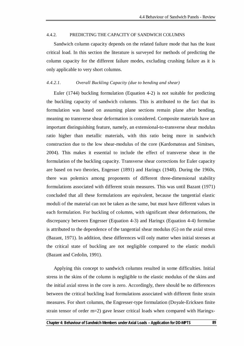
4.4 Behaviour of Sandwich Panels - Review
Chapter 4: Behaviour of Sandwich Members under Axial Loads – Application for DD-MPTS
89
4.4.2. PREDICTING THE CAPACITY OF SANDWICH COLUMNS
Sandwich column capacity depends on the related failure mode that has the least
critical load. In this section the literature is surveyed for methods of predicting the
column capacity for the different failure modes, excluding crushing failure as it is
only applicable to very short columns.
4.4.2.1. Overall Buckling Capacity (due to bending and shear)
Euler (1744) buckling formulation (Equation 4-2) is not suitable for predicting
the buckling capacity of sandwich columns. This is attributed to the fact that its
formulation was based on assuming plane sections remain plane after bending,
meaning no transverse shear deformation is considered. Composite materials have an
important distinguishing feature, namely, an extensional-to-transverse shear modulus
ratio higher than metallic materials, with this ratio being more in sandwich
construction due to the low shear-modulus of the core (Kardomateas and Simitses,
2004). This makes it essential to include the effect of transverse shear in the
formulation of the buckling capacity. Transverse shear corrections for Euler capacity
are based on two theories, Engesser (1891) and Haringx (1948). During the 1960s,
there was polemics among proponents of different three-dimensional stability
formulations associated with different strain measures. This was until Bazant (1971)
concluded that all these formulations are equivalent, because the tangential elastic
moduli of the material can not be taken as the same, but must have different values in
each formulation. For buckling of columns, with significant shear deformations, the
discrepancy between Engesser (Equation 4-3) and Haringx (Equation 4-4) formulae
is attributed to the dependence of the tangential shear modulus (G) on the axial stress
(Bazant, 1971). In addition, these differences will only matter when initial stresses at
the critical state of buckling are not negligible compared to the elastic moduli
(Bazant and Cedolin, 1991).
Applying this concept to sandwich columns resulted in some difficulties. Initial
stress in the skins of the column is negligible to the elastic modulus of the skins and
the initial axial stress in the core is zero. Accordingly, there should be no differences
between the critical buckling load formulations associated with different finite strain
measures. For short columns, the Engresser-type formulation (Doyale-Ericksen finite
strain tensor of order m=2) gave lesser critical loads when compared with Haringx-
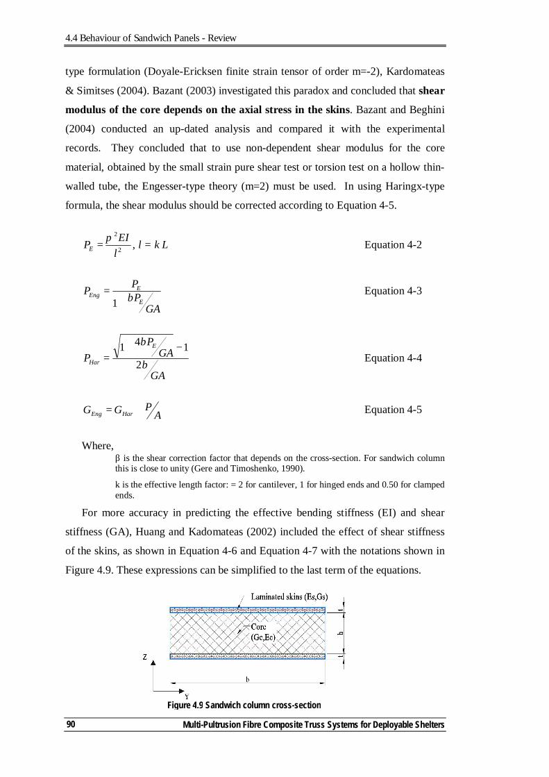
4.4 Behaviour of Sandwich Panels - Review
Multi-Pultrusion Fibre Composite Truss Systems for Deployable Shelters
90
type formulation (Doyale-Ericksen finite strain tensor of order m=-2), Kardomateas
& Simitses (2004). Bazant (2003) investigated this paradox and concluded that shear
modulus of the core depends on the axial stress in the skins. Bazant and Beghini
(2004) conducted an up-dated analysis and compared it with the experimental
records. They concluded that to use non-dependent shear modulus for the core
material, obtained by the small strain pure shear test or torsion test on a hollow thin-
walled tube, the Engesser-type theory (m=2) must be used. In using Haringx-type
formula, the shear modulus should be corrected according to Equation 4-5.
2
2
lEIPE
π= , l = k L Equation 4-2
GAPPP
E
EEng β+
=1
Equation 4-3
GA
GAP
PE
Har β
β
2141 −+
= Equation 4-4
APGG HarEng += Equation 4-5
Where, β is the shear correction factor that depends on the cross-section. For sandwich column this is close to unity (Gere and Timoshenko, 1990).
k is the effective length factor: = 2 for cantilever, 1 for hinged ends and 0.50 for clamped ends.
For more accuracy in predicting the effective bending stiffness (EI) and shear
stiffness (GA), Huang and Kadomateas (2002) included the effect of shear stiffness
of the skins, as shown in Equation 4-6 and Equation 4-7 with the notations shown in
Figure 4.9. These expressions can be simplified to the last term of the equations.
Figure 4.9 Sandwich column cross-section
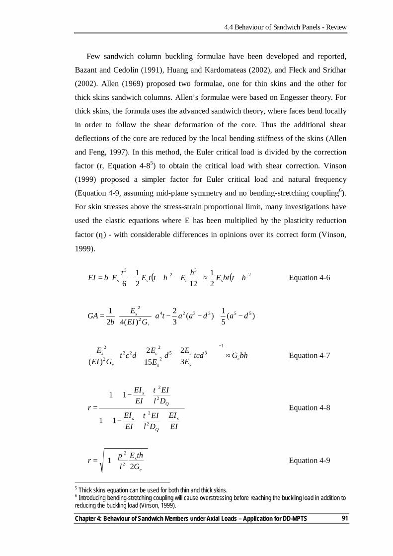
4.4 Behaviour of Sandwich Panels - Review
Chapter 4: Behaviour of Sandwich Members under Axial Loads – Application for DD-MPTS
91
Few sandwich column buckling formulae have been developed and reported,
Bazant and Cedolin (1991), Huang and Kardomateas (2002), and Fleck and Sridhar
(2002). Allen (1969) proposed two formulae, one for thin skins and the other for
thick skins sandwich columns. Allen’s formulae were based on Engesser theory. For
thick skins, the formula uses the advanced sandwich theory, where faces bend locally
in order to follow the shear deformation of the core. Thus the additional shear
deflections of the core are reduced by the local bending stiffness of the skins (Allen
and Feng, 1997). In this method, the Euler critical load is divided by the correction
factor (r, Equation 4-85) to obtain the critical load with shear correction. Vinson
(1999) proposed a simpler factor for Euler critical load and natural frequency
(Equation 4-9, assuming mid-plane symmetry and no bending-stretching coupling6).
For skin stresses above the stress-strain proportional limit, many investigations have
used the elastic equations where E has been multiplied by the plasticity reduction
factor (η) - with considerable differences in opinions over its correct form (Vinson,
1999).
( ) ( )23
23
21
1221
6htbtEhEhttEtEbEI scss +≈
+++= Equation 4-6
+
−+−−
= )(
51)(
32
)(421 553324
2
2
dadaataGEI
Eb
GAs
s
bhGtcdEEd
EEdct
GEIE
cs
c
s
c
c
s ≈
++
−135
2
222
2
2
32
152
)( Equation 4-7
−+
−+
=
EIEI
DlEI
EIEI
DlEI
EIEI
rs
Q
s
Q
s
2
2
2
2
11
11
τ
τ
Equation 4-8
+=
c
s
GthE
lr
21 2
2π Equation 4-9
5 Thick skins equation can be used for both thin and thick skins. 6 Introducing bending-stretching coupling will cause overstressing before reaching the buckling load in addition to reducing the buckling load (Vinson, 1999).
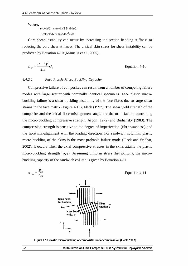
4.4 Behaviour of Sandwich Panels - Review
Multi-Pultrusion Fibre Composite Truss Systems for Deployable Shelters
92
Where, a=t+(h/2), c=(t+h)/2 & d=h/2
EIs=Esbt3/6 & DQ=4bc2Gc/h
Core shear instability can occur by increasing the section bending stiffness or
reducing the core shear stiffness. The critical skin stress for shear instability can be
predicted by Equation 4-10 (Mamalis et al., 2005).
ccr Ghtht
2)( 2+
=σ Equation 4-10
4.4.2.2. Face Plastic Micro-Buckling Capacity
Compressive failure of composites can result from a number of competing failure
modes with large scatter with nominally identical specimens. Face plastic micro-
buckling failure is a shear buckling instability of the face fibres due to large shear
strains in the face matrix (Figure 4.10), Fleck (1997). The shear yield strength of the
composite and the initial fibre misalignment angle are the main factors controlling
the micro-buckling compressive strength, Argon (1972) and Budiansky (1983). The
compression strength is sensitive to the degree of imperfection (fibre waviness) and
the fibre mis-alignment with the loading direction. For sandwich columns, plastic
micro-buckling of the skins is the most probable failure mode (Fleck and Sridhar,
2002). It occurs when the axial compressive stresses in the skins attains the plastic
micro-buckling strength (σmb). Assuming uniform stress distributions, the micro-
buckling capacity of the sandwich column is given by Equation 4-11.
btPmb
mb 2=σ Equation 4-11
Figure 4.10 Plastic micro-buckling of composites under compression (Fleck, 1997)
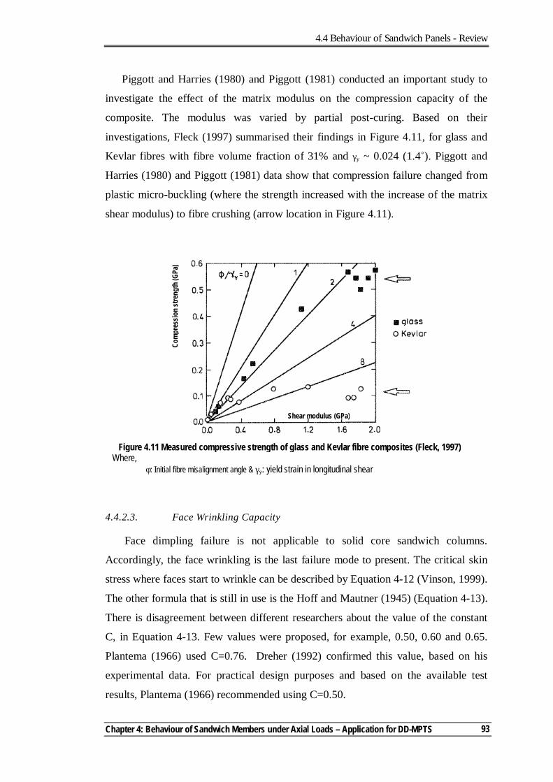
4.4 Behaviour of Sandwich Panels - Review
Chapter 4: Behaviour of Sandwich Members under Axial Loads – Application for DD-MPTS
93
Piggott and Harries (1980) and Piggott (1981) conducted an important study to
investigate the effect of the matrix modulus on the compression capacity of the
composite. The modulus was varied by partial post-curing. Based on their
investigations, Fleck (1997) summarised their findings in Figure 4.11, for glass and
Kevlar fibres with fibre volume fraction of 31% and γy ~ 0.024 (1.4˚). Piggott and
Harries (1980) and Piggott (1981) data show that compression failure changed from
plastic micro-buckling (where the strength increased with the increase of the matrix
shear modulus) to fibre crushing (arrow location in Figure 4.11).
4.4.2.3. Face Wrinkling Capacity
Face dimpling failure is not applicable to solid core sandwich columns.
Accordingly, the face wrinkling is the last failure mode to present. The critical skin
stress where faces start to wrinkle can be described by Equation 4-12 (Vinson, 1999).
The other formula that is still in use is the Hoff and Mautner (1945) (Equation 4-13).
There is disagreement between different researchers about the value of the constant
C, in Equation 4-13. Few values were proposed, for example, 0.50, 0.60 and 0.65.
Plantema (1966) used C=0.76. Dreher (1992) confirmed this value, based on his
experimental data. For practical design purposes and based on the available test
results, Plantema (1966) recommended using C=0.50.
Figure 4.11 Measured compressive strength of glass and Kevlar fibre composites (Fleck, 1997) Where, φ: Initial fibre misalignment angle & γy: yield strain in longitudinal shear
Shear modulus (GPa)
Com
pres
sion
stre
ngth
(GPa
)

4.4 Behaviour of Sandwich Panels - Review
Multi-Pultrusion Fibre Composite Truss Systems for Deployable Shelters
94
2/1
)1(32
−=
yxxy
sysxccr
EEEht
ννσ Equation 4-12
[ ] 3/1 ccscr GEEC=σ Equation 4-13
The above equations refer to isotropic face and core materials. For orthotropic
cores, Vonach and Rammerstorfer (2000) suggested Equation 4-14, with C=0.85.
[ ] 3/1 2)( thickscr kEC=σ Equation 4-14
Where,
4
1
13241
3
2
4 )(cz
cxcz
cz
cxzxc
thick
EEE
EEXXXXk
−
−+
−= µµν
µµ;
22
21
1322
3 µµνµ
−+
= cccxz DDX ;
22
21
1321
4 µµνµ
−+
= cccxz DDX ;
121 −+= ξξµ ; 12
2 −−= ξξµ ; 13
31
c
cc
DDD
=ξ ;
cxc ED =1 ; cxzcxzcx
cxzcxc GE
GEDν2
213 −
= ; and czc ED =3 .
Gdoutos et al (2003) stated that the difference in the predicted critical stress,
between using Equation 4-13 (assuming isotropic core material) and Equation 4-14,
is less than 5% for the Ecx/Ecz ratio of 10-100%. However, for highly orthotropic core
properties, the critical stress will be reduced significantly.
4.4 Behaviour of Sandwich Panels - Review
Chapter 4: Behaviour of Sandwich Members under Axial Loads – Application for DD-MPTS
95
4.4.2.4. Failure Predictions in Composite Materials
From the review presented above, it is clear that there are differences in opinion
in predicting the capacity of some of the failure modes of sandwich columns. Using
laminates for the column skins adds more complexity in predicting their capacities.
This is due to the lack of understanding of the mechanisms that lead to failure in
composite materials. This is especially true for matrix or fibres under compression
(Davila et al, 2005). This explains the generally poor predictions by most of the
participants in the World-Wide Failure Exercise (WWFE). The current design
practices place little or no reliance on the ability to predict the ultimate strength of
the composite structure with any great accuracy. Failure theories are often used in the
initial calculations to size the structure. Then experimental tests on coupons or
structural elements are used to determine the global design allowables, which are
usually less than 30% of the ultimate load (Soden et al, 1998). The issue addressed
was the definition of failure. A designer would define failure as the point at which
the structure ceases to fulfil its function. This definition is accordingly application-
specific. It was concluded that the connection between events at the lamina level and
the definitions of structural failure required by designers need to be established
(Hinton and Soden, 1998).
The comparison, conducted by the organisers of the WWFE, between theoretical
and experimental results, showed that failure theories of Puck (Puck and Schurmann,
1998 & 2002), Zinoviev (Zinoviev et al., 1998 & 2002), Tsai (Liu and Tsai, 1998 &
Kuraishi, et al., 2002) and Sun (Sun and Tao, 1998, and Sun et al., 2002) are the top
ranking theories, based on the available experimental data (Hinton et al, 2002a and
2002b). The assessment was based on five major areas that are summarised as
follows:
- Biaxial strength of unidirectional laminae. Most theories achieved at least
50% of the experimental data with the closest by Tsai, Wolfe (Wolfe and
Butalia, 1998 & Butalia and Wolfe, 2002), Puck and Chamis (Gotsis et al.,
1998 & 2002). It was noticed that Tsai and Wolfe predict markedly higher
strength levels than other theories, in the compression-compression (C-C) or
tension-tension (T-T) quadrants for certain stress ratios. The lack of
4.4 Behaviour of Sandwich Panels - Review
Multi-Pultrusion Fibre Composite Truss Systems for Deployable Shelters
96
experimental data in these quadrants avoided justifying their performance
under these loading conditions.
- Predicting initial strengths of multi-directional laminates. Most of the
theories failed to capture the laminate initial strength. The overall
conclusion was that, to estimate the stress levels at which initial failure
might occur in a multi-directional laminate, the current theories can predict
this by an accuracy of +50% at best. This is partly due to residual stresses
and in-situ lamina properties.
- Predicting final strengths of multi-directional laminates. Puck, Tsai, and
Zinoviev outperformed other theories. This was attributed to their ability to
model post-initial failure. At best, using these theories would estimate the
ultimate failure within +10% in 40% of the cases.
- Ability to predict a selection of general features: Puck and Tsai showed the
best performance of this category. They predicted the increase in shear
strength when transverse compression stresses were applied to the lamina.
Based on the above overview, it is clear that laminate failure is difficult to assess
theoretically and, accordingly, numerically. Tsai’s theory is one of the best available
theories in predicting the failure of the laminate. It employs the interactive Tsai-Wu
failure criterion which is one of the best-known and mathematically satisfying
theories (Hinton et al, 2002b). However, like many of the other theories, this theory
is linear-elastic and it can not predict the large non-linear strains observed in tests
with high lamina shear.
4.5. SINGLE-CORE PROTOTYPE COLUMNS TESTING PROGRAM
After conducting the preliminary column testing, it became clear that the core
material properties dominated the compression capacity of the columns with two
modes of failures - shear buckling and micro-buckling skin failure. The prototype
column test program was divided into two parts: the first used single core material,
the second used mixed core (pink foam-balsa7 combination). This section details the
specimen preparations, test observations and FE modelling for the single-core
columns. Details of the mixed-core columns are presented in Appendix C. 7 Balsa was used due its availability as a high-shear modulus alternative
4.5 Single-Core Prototype Testing Program
Chapter 4: Behaviour of Sandwich Members under Axial Loads – Application for DD-MPTS
97
4.5.1. SPECIMEN PREPARATIONS
Ten prototype columns of 550mmL8x120mmWx24mmThk were manufactured.
Pink foam was used in five columns (T02-01) and end-grain balsa was used in five
columns (T02-06). Columns were manufactured as follows:
- Skins were laminated from 3 plies of uni-glass 450gsm from Huntsman
(www.huntsman.ivt.com.au) using Hyrez 202 epoxy-resin with peel plies at
each face.
- After curing for 24 hours at room temperature, the laminated sheets were cut
to 140mm wide by 600mm length, using a bench saw with diamond-coated
cutting wheel.
- Core material was cut to 140mm width by 600mm length with a thickness of
20mm, using a band saw.
- Cores were vacuumed, using a normal vacuum cleaner, to remove dust.
- Cores were primed, by spraying Hyrez 202 epoxy. This process needed
about three coats, to achieve a permanent glossy surface. This was to control
the amount of adhesive absorbed through the core gaps and to achieve good
bonding between the core and the skins.
- The core of each column was weighed before and after spraying to assess
the amount of resin used.
- The primed core was allowed to cure for 24 hours at room temperature.
After removing the peel plies, skins9 were glued to the core material using
the HPR26 thixotropic-toughened epoxy glue system from ATL Composites
(www.atlcomposites.com.au).
- The columns were clamped in bundles of three to maximise the exclusion of
excess glue and left to cure for 24 hours at room temperature (Figure 4.12).
- Columns were cut to dimension (120mmW x 550mmL) on a bench saw
with diamond-coated blade.
8 460mm clear height. 9 After removing the peel plies.
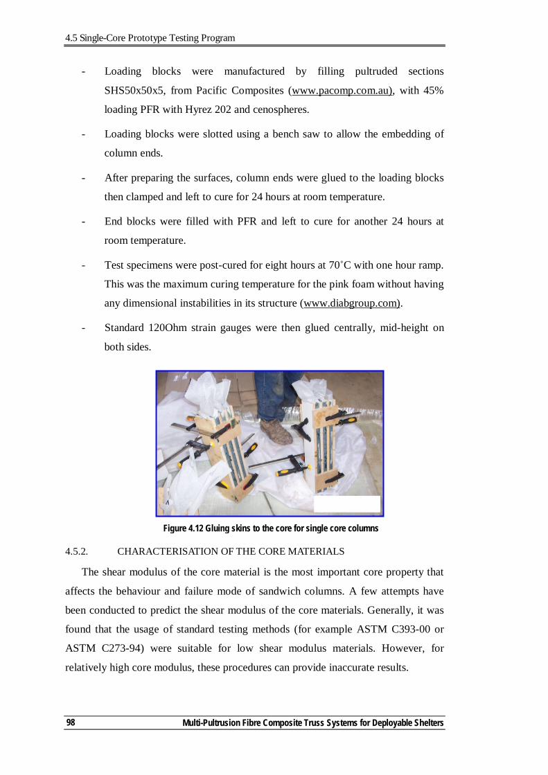
4.5 Single-Core Prototype Testing Program
Multi-Pultrusion Fibre Composite Truss Systems for Deployable Shelters
98
- Loading blocks were manufactured by filling pultruded sections
SHS50x50x5, from Pacific Composites (www.pacomp.com.au), with 45%
loading PFR with Hyrez 202 and cenospheres.
- Loading blocks were slotted using a bench saw to allow the embedding of
column ends.
- After preparing the surfaces, column ends were glued to the loading blocks
then clamped and left to cure for 24 hours at room temperature.
- End blocks were filled with PFR and left to cure for another 24 hours at
room temperature.
- Test specimens were post-cured for eight hours at 70˚C with one hour ramp.
This was the maximum curing temperature for the pink foam without having
any dimensional instabilities in its structure (www.diabgroup.com).
- Standard 120Ohm strain gauges were then glued centrally, mid-height on
both sides.
4.5.2. CHARACTERISATION OF THE CORE MATERIALS
The shear modulus of the core material is the most important core property that
affects the behaviour and failure mode of sandwich columns. A few attempts have
been conducted to predict the shear modulus of the core materials. Generally, it was
found that the usage of standard testing methods (for example ASTM C393-00 or
ASTM C273-94) were suitable for low shear modulus materials. However, for
relatively high core modulus, these procedures can provide inaccurate results.
Figure 4.12 Gluing skins to the core for single core columns
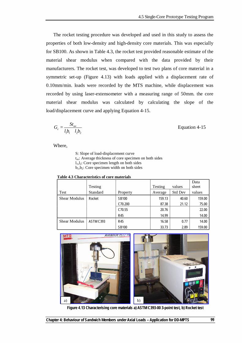
4.5 Single-Core Prototype Testing Program
Chapter 4: Behaviour of Sandwich Members under Axial Loads – Application for DD-MPTS
99
The rocket testing procedure was developed and used in this study to assess the
properties of both low-density and high-density core materials. This was especially
for SB100. As shown in Table 4.3, the rocket test provided reasonable estimate of the
material shear modulus when compared with the data provided by their
manufacturers. The rocket test, was developed to test two plans of core material in a
symmetric set-up (Figure 4.13) with loads applied with a displacement rate of
0.10mm/min. loads were recorded by the MTS machine, while displacement was
recorded by using laser-extensometer with a measuring range of 50mm. the core
material shear modulus was calculated by calculating the slope of the
load/displacement curve and applying Equation 4-15.
2211 blblStG av
c += Equation 4-15
Where, S: Slope of load-displacement curve tav: Average thickness of core specimen on both sides l1,l2: Core specimen length on both sides b1,b2: Core specimen width on both sides
Table 4.3 Characteristics of core materials
Testing Testing values Data sheet
Test Standard Property Average Std Dev values Shear Modulus Rocket SB100 159.13 40.60 159.00 C70.200 87.38 21.12 75.00 C70.55 20.76 22.00 R45 14.99 14.00 Shear Modulus ASTM C393 R45 16.58 0.77 14.00 SB100 33.73 2.89 159.00
Figure 4.13 Characterising core materials a) ASTM C393-00 3-point test, b) Rocket test
a) b)
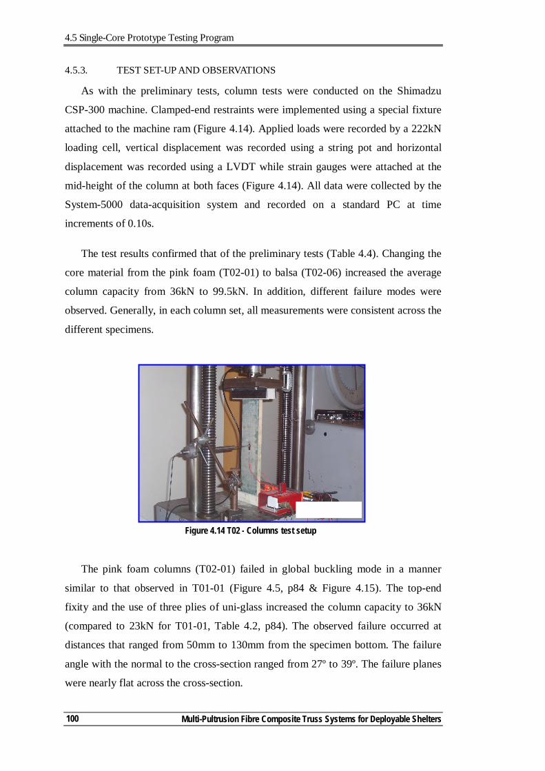
4.5 Single-Core Prototype Testing Program
Multi-Pultrusion Fibre Composite Truss Systems for Deployable Shelters
100
4.5.3. TEST SET-UP AND OBSERVATIONS
As with the preliminary tests, column tests were conducted on the Shimadzu
CSP-300 machine. Clamped-end restraints were implemented using a special fixture
attached to the machine ram (Figure 4.14). Applied loads were recorded by a 222kN
loading cell, vertical displacement was recorded using a string pot and horizontal
displacement was recorded using a LVDT while strain gauges were attached at the
mid-height of the column at both faces (Figure 4.14). All data were collected by the
System-5000 data-acquisition system and recorded on a standard PC at time
increments of 0.10s.
The test results confirmed that of the preliminary tests (Table 4.4). Changing the
core material from the pink foam (T02-01) to balsa (T02-06) increased the average
column capacity from 36kN to 99.5kN. In addition, different failure modes were
observed. Generally, in each column set, all measurements were consistent across the
different specimens.
The pink foam columns (T02-01) failed in global buckling mode in a manner
similar to that observed in T01-01 (Figure 4.5, p84 & Figure 4.15). The top-end
fixity and the use of three plies of uni-glass increased the column capacity to 36kN
(compared to 23kN for T01-01, Table 4.2, p84). The observed failure occurred at
distances that ranged from 50mm to 130mm from the specimen bottom. The failure
angle with the normal to the cross-section ranged from 27º to 39º. The failure planes
were nearly flat across the cross-section.
Figure 4.14 T02 - Columns test setup
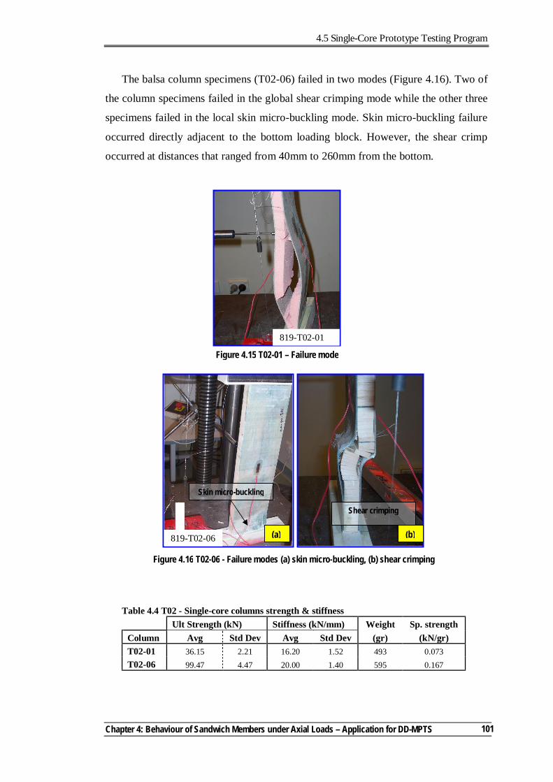
4.5 Single-Core Prototype Testing Program
Chapter 4: Behaviour of Sandwich Members under Axial Loads – Application for DD-MPTS
101
The balsa column specimens (T02-06) failed in two modes (Figure 4.16). Two of
the column specimens failed in the global shear crimping mode while the other three
specimens failed in the local skin micro-buckling mode. Skin micro-buckling failure
occurred directly adjacent to the bottom loading block. However, the shear crimp
occurred at distances that ranged from 40mm to 260mm from the bottom.
Table 4.4 T02 - Single-core columns strength & stiffness Ult Strength (kN) Stiffness (kN/mm) Weight Sp. strength Column Avg Std Dev Avg Std Dev (gr) (kN/gr) T02-01 36.15 2.21 16.20 1.52 493 0.073 T02-06 99.47 4.47 20.00 1.40 595 0.167
Figure 4.15 T02-01 – Failure mode
819-T02-01
Figure 4.16 T02-06 - Failure modes (a) skin micro-buckling, (b) shear crimping
Skin micro-buckling
Shear crimping
(a) (b) 819-T02-06
4.5 Single-Core Prototype Testing Program
Multi-Pultrusion Fibre Composite Truss Systems for Deployable Shelters
102
Comparing the weight of both columns, T02-06 was 20% heavier than T02-01.
The associated increase in strength was 128%. The column stiffness was measured
by calculating the slope of the load deflection curves, at the straight portion. The
column stiffness of T02-06 was slightly higher when compared with that of the T02-
01 column. This indicated that the core material had limited effect on the column
stiffness but had major effect on its strength.
4.5.4. FE MODELLING
As discussed in Sec.3.5 (p44), Solid-Shell FE model predictions have good
correlation with the sandwich columns’ experimental records. Abaqus is a
Lagrangian code (Hibbitt et al, 2004b). Accordingly, its formulation is similar to an
Engesser-type formula, with the core properties obtained from the direct shear tests
with independent values of the axial stress in the skins. Accordingly, standard
modelling procedures were used without the need to develop special sub-routines to
change the material stiffness matrix during execution.
In modelling the T02 columns, a Solid-Shell model (CSO) was used, similar to
the diagonal model presented in Chapter 3. Thick shell elements were used for the
skins with composite properties for each ply, and solid elements were used for the
glue and the core. The core material was modelled as an elastic material10. An
average glue thickness of 0.5mm was used11. Surface-to-surface tie constraints were
used to join each part of the model. For a more detailed description of the model,
reference should be made to Sec.3.5.2 (p47).
Abaqus computes the shell transverse-shear stiffness by matching the shear
response for the case of the shell bending about one axis, using a parabolic variation
of transverse-shear stress in each layer. Generally, this approach provides a
reasonable estimate of the shear flexibility of the shell. It also provides estimates of
inter-laminar shear stresses in composite shells (Hibbitt et al, 2004b). In calculating
the transverse-shear stiffness, Abaqus assumes that the shell section directions are
the principal bending directions (bending about one principal direction does not 10 The foam-crushed model was not required, as the core was not subjected to crushing strain under any load condition (unlike beam testing, where crush could occur at the load application and support locations). Using the foam-crushing material model complicated the analysis. In addition, it needed the conduct of additional tests for the core material, like assessing the hydrostatic tensile and compressive strengths to define the yield surface (Hibbitt, 2004a). 11 The average glue thicknesses ranged from 0.40-0.50mm.
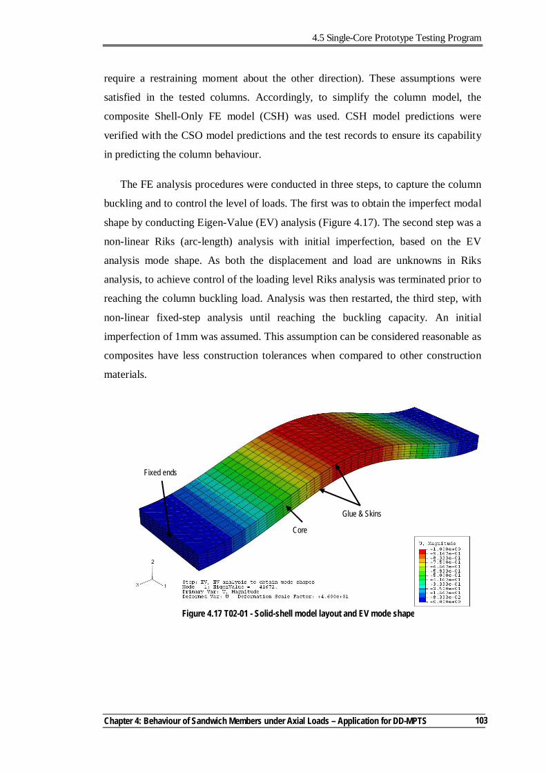
4.5 Single-Core Prototype Testing Program
Chapter 4: Behaviour of Sandwich Members under Axial Loads – Application for DD-MPTS
103
require a restraining moment about the other direction). These assumptions were
satisfied in the tested columns. Accordingly, to simplify the column model, the
composite Shell-Only FE model (CSH) was used. CSH model predictions were
verified with the CSO model predictions and the test records to ensure its capability
in predicting the column behaviour.
The FE analysis procedures were conducted in three steps, to capture the column
buckling and to control the level of loads. The first was to obtain the imperfect modal
shape by conducting Eigen-Value (EV) analysis (Figure 4.17). The second step was a
non-linear Riks (arc-length) analysis with initial imperfection, based on the EV
analysis mode shape. As both the displacement and load are unknowns in Riks
analysis, to achieve control of the loading level Riks analysis was terminated prior to
reaching the column buckling load. Analysis was then restarted, the third step, with
non-linear fixed-step analysis until reaching the buckling capacity. An initial
imperfection of 1mm was assumed. This assumption can be considered reasonable as
composites have less construction tolerances when compared to other construction
materials.
Figure 4.17 T02-01 - Solid-shell model layout and EV mode shape
Core
Glue & Skins
Fixed ends
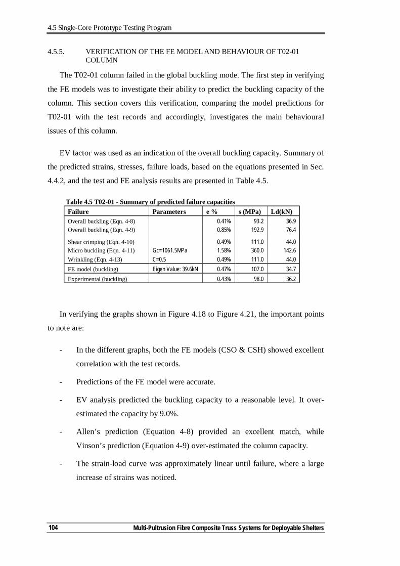
4.5 Single-Core Prototype Testing Program
Multi-Pultrusion Fibre Composite Truss Systems for Deployable Shelters
104
4.5.5. VERIFICATION OF THE FE MODEL AND BEHAVIOUR OF T02-01 COLUMN
The T02-01 column failed in the global buckling mode. The first step in verifying
the FE models was to investigate their ability to predict the buckling capacity of the
column. This section covers this verification, comparing the model predictions for
T02-01 with the test records and accordingly, investigates the main behavioural
issues of this column.
EV factor was used as an indication of the overall buckling capacity. Summary of
the predicted strains, stresses, failure loads, based on the equations presented in Sec.
4.4.2, and the test and FE analysis results are presented in Table 4.5.
Table 4.5 T02-01 - Summary of predicted failure capacities Failure Parameters ε % σ(MPa) Ld(kN) Overall buckling (Eqn. 4-8) 0.41% 93.2 36.9 Overall buckling (Eqn. 4-9) 0.85% 192.9 76.4
Shear crimping (Eqn. 4-10) 0.49% 111.0 44.0 Micro buckling (Eqn. 4-11) Gc=1061.5MPa 1.58% 360.0 142.6 Wrinkling (Eqn. 4-13) C=0.5 0.49% 111.0 44.0 FE model (buckling) Eigen Value: 39.6kN 0.47% 107.0 34.7 Experimental (buckling) 0.43% 98.0 36.2
In verifying the graphs shown in Figure 4.18 to Figure 4.21, the important points
to note are:
- In the different graphs, both the FE models (CSO & CSH) showed excellent
correlation with the test records.
- Predictions of the FE model were accurate.
- EV analysis predicted the buckling capacity to a reasonable level. It over-
estimated the capacity by 9.0%.
- Allen’s prediction (Equation 4-8) provided an excellent match, while
Vinson’s prediction (Equation 4-9) over-estimated the column capacity.
- The strain-load curve was approximately linear until failure, where a large
increase of strains was noticed.
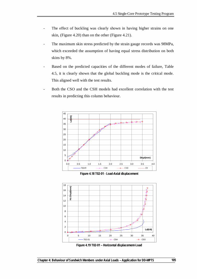
4.5 Single-Core Prototype Testing Program
Chapter 4: Behaviour of Sandwich Members under Axial Loads – Application for DD-MPTS
105
- The effect of buckling was clearly shown in having higher strains on one
skin, (Figure 4.20) than on the other (Figure 4.21).
- The maximum skin stress predicted by the strain gauge records was 98MPa,
which exceeded the assumption of having equal stress distribution on both
skins by 8%.
- Based on the predicted capacities of the different modes of failure, Table
4.5, it is clearly shown that the global buckling mode is the critical mode.
This aligned well with the test results.
- Both the CSO and the CSH models had excellent correlation with the test
results in predicting this column behaviour.
Figure 4.18 T02-01 - Load-Axial displacement
0
5
10
15
20
25
30
35
40
45
0.0 0.5 1.0 1.5 2.0 2.5 3.0 3.5 4.0
Displ(mm)
Ld(k
N)
T02-01 CSH CSO EV
Figure 4.19 T02-01 – Horizontal displacement-Load
0
2
4
6
8
10
12
14
16
18
0 5 10 15 20 25 30 35 40
Ld(kN)
Hz
Dis
pl(m
m)
T02-01 CSH CSO
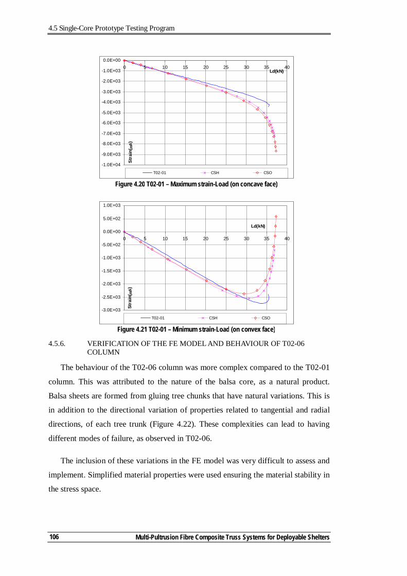
4.5 Single-Core Prototype Testing Program
Multi-Pultrusion Fibre Composite Truss Systems for Deployable Shelters
106
4.5.6. VERIFICATION OF THE FE MODEL AND BEHAVIOUR OF T02-06 COLUMN
The behaviour of the T02-06 column was more complex compared to the T02-01
column. This was attributed to the nature of the balsa core, as a natural product.
Balsa sheets are formed from gluing tree chunks that have natural variations. This is
in addition to the directional variation of properties related to tangential and radial
directions, of each tree trunk (Figure 4.22). These complexities can lead to having
different modes of failure, as observed in T02-06.
The inclusion of these variations in the FE model was very difficult to assess and
implement. Simplified material properties were used ensuring the material stability in
the stress space.
Figure 4.20 T02-01 – Maximum strain-Load (on concave face)
-1.0E+04
-9.0E+03
-8.0E+03
-7.0E+03
-6.0E+03
-5.0E+03
-4.0E+03
-3.0E+03
-2.0E+03
-1.0E+03
0.0E+000 5 10 15 20 25 30 35 40
Ld(kN)
Stra
in( µ
s)
T02-01 CSH CSO
Figure 4.21 T02-01 – Minimum strain-Load (on convex face)
-3.0E+03
-2.5E+03
-2.0E+03
-1.5E+03
-1.0E+03
-5.0E+02
0.0E+00
5.0E+02
1.0E+03
0 5 10 15 20 25 30 35 40
Ld(kN)
Stra
in( µ
s)
T02-01 CSH CSO
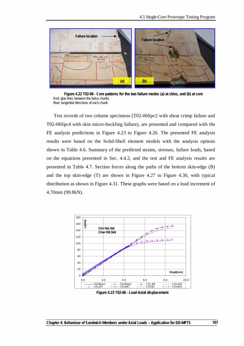
4.5 Single-Core Prototype Testing Program
Chapter 4: Behaviour of Sandwich Members under Axial Loads – Application for DD-MPTS
107
Test records of two column specimens (T02-06Spc2 with shear crimp failure and
T02-06Spc4 with skin micro-buckling failure), are presented and compared with the
FE analysis predictions in Figure 4.23 to Figure 4.26. The presented FE analysis
results were based on the Solid-Shell element models with the analysis options
shown in Table 4.6. Summary of the predicted strains, stresses, failure loads, based
on the equations presented in Sec. 4.4.2, and the test and FE analysis results are
presented in Table 4.7. Section forces along the paths of the bottom skin-edge (B)
and the top skin-edge (T) are shown in Figure 4.27 to Figure 4.30, with typical
distribution as shown in Figure 4.31. These graphs were based on a load increment of
4.70mm (99.8kN).
Figure 4.22 T02-06 - Core patterns for the two failure modes (a) at skins, and (b) at core Red: glue lines between the balsa chunks Blue: tangential directions of each chunk
(a) (b)
Failure location Failure location
Figure 4.23 T02-06 - Load-Axial displacement
0
20
40
60
80
100
120
140
160
180
0.0 2.0 4.0 6.0 8.0 10.0
Displ(mm)
Ld(k
N)
T02-06Spc2 T02-06Spc4 CSO_iR0 CSO-w R0CSO_iR1 CSO-wR1 CSO-iR2 CSO-w R2
EVi=156.1kN EVw=109.5kN
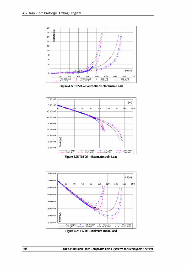
4.5 Single-Core Prototype Testing Program
Multi-Pultrusion Fibre Composite Truss Systems for Deployable Shelters
108
Figure 4.24 T02-06 – Horizontal displacement-Load
0
2
4
6
8
10
12
14
16
18
20
0 20 40 60 80 100 120 140 160 180
Ld(kN)
Hz
Def
l(mm
)
T02-06Spc2 T02-06Spc4 CSO_iR0 CSO-w R0CSO_iR1 CSO-w R1 CSO-iR2 CSO-w R2
Figure 4.25 T02-06 – Maximum strain-Load
-3.5E+04
-3.0E+04
-2.5E+04
-2.0E+04
-1.5E+04
-1.0E+04
-5.0E+03
0.0E+00
5.0E+03
0 20 40 60 80 100 120 140 160 180
Ld(kN)
Stra
in( µ
s)
T02-06Spc2 T02-06Spc4 CSO_iR0 CSO-w R0CSO_iR1 CSO-w R1 CSO-iR2 CSO-w R2
Figure 4.26 T02-06 - Minimum strain-Load
-1.2E+04
-1.0E+04
-8.0E+03
-6.0E+03
-4.0E+03
-2.0E+03
0.0E+00
2.0E+03
0 20 40 60 80 100 120 140 160 180
Ld(kN)
Stra
in( µ
s)
T02-06Spc2 T02-06Spc4 CSO_iR0 CSO-w R0CSO_iR1 CSO-w R1 CSO-iR2 CSO-w R2
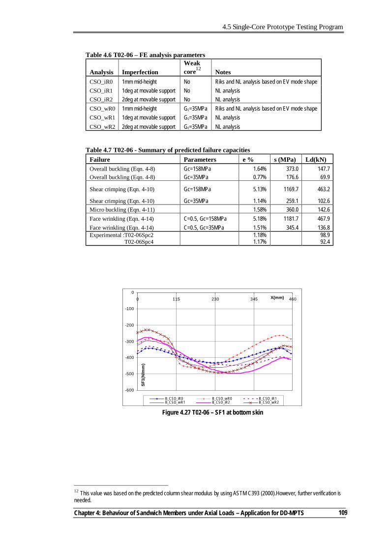
4.5 Single-Core Prototype Testing Program
Chapter 4: Behaviour of Sandwich Members under Axial Loads – Application for DD-MPTS
109
Table 4.6 T02-06 – FE analysis parameters
Analysis Imperfection Weak core12 Notes
CSO_iR0 1mm mid-height No Riks and NL analysis based on EV mode shape CSO_iR1 1deg at movable support No NL analysis CSO_iR2 2deg at movable support No NL analysis CSO_wR0 1mm mid-height Gc=35MPa Riks and NL analysis based on EV mode shape CSO_wR1 1deg at movable support Gc=35MPa NL analysis CSO_wR2 2deg at movable support Gc=35MPa NL analysis
Table 4.7 T02-06 - Summary of predicted failure capacities Failure Parameters ε % σ(MPa) Ld(kN) Overall buckling (Eqn. 4-8) Gc=158MPa 1.64% 373.0 147.7 Overall buckling (Eqn. 4-8) Gc=35MPa 0.77% 176.6 69.9
Shear crimping (Eqn. 4-10) Gc=158MPa 5.13% 1169.7 463.2
Shear crimping (Eqn. 4-10) Gc=35MPa 1.14% 259.1 102.6 Micro buckling (Eqn. 4-11) 1.58% 360.0 142.6 Face wrinkling (Eqn. 4-14) C=0.5, Gc=158MPa 5.18% 1181.7 467.9 Face wrinkling (Eqn. 4-14) C=0.5, Gc=35MPa 1.51% 345.4 136.8 Experimental :T02-06Spc2
T02-06Spc4 1.18% 1.17%
98.9 92.4
12 This value was based on the predicted column shear modulus by using ASTM C393 (2000).However, further verification is needed.
Figure 4.27 T02-06 – SF1 at bottom skin
-600
-500
-400
-300
-200
-100
00 115 230 345 460X(mm)
SF1(
N/m
m)
B_CSO_iR0 B_CSO_w R0 B_CSO_iR1B_CSO_w R1 B_CSO_iR2 B_CSO_w R2
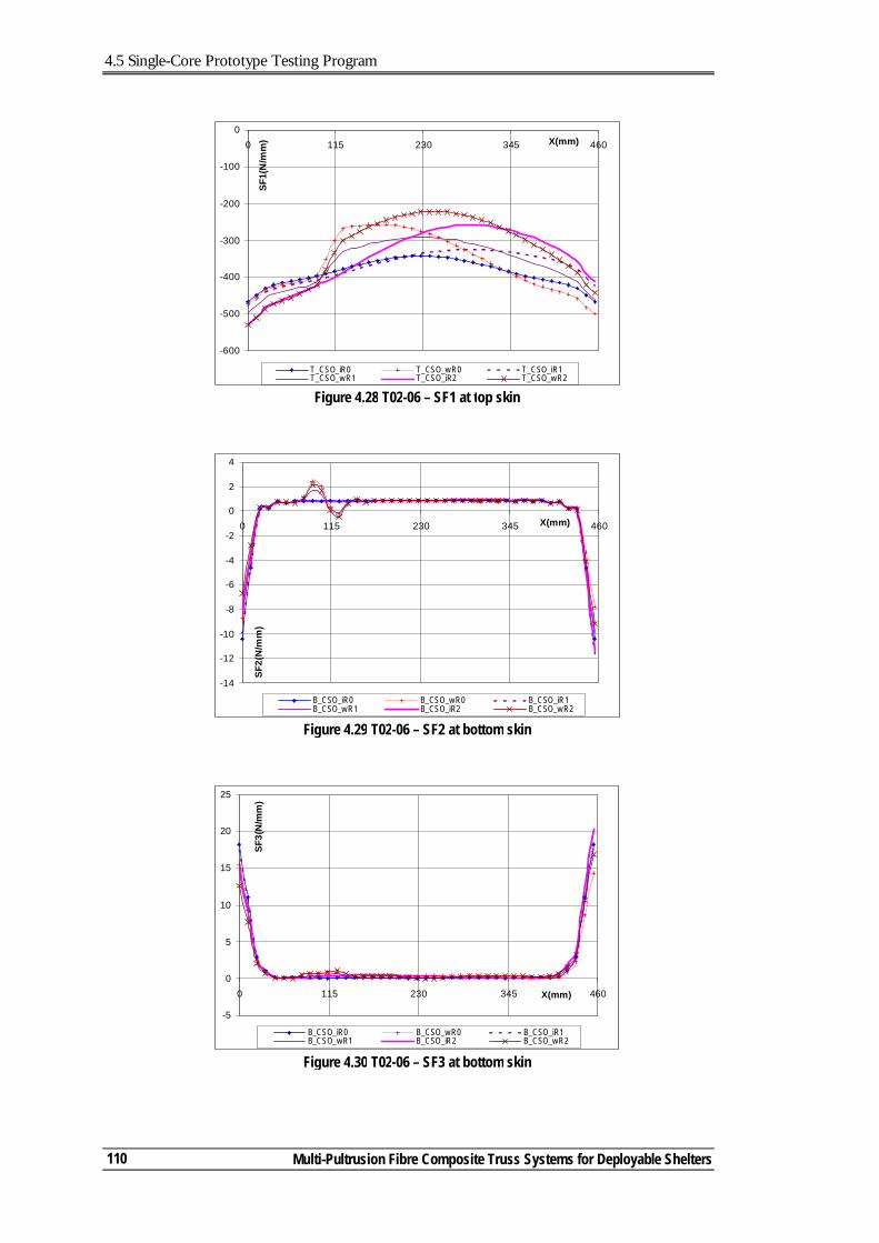
4.5 Single-Core Prototype Testing Program
Multi-Pultrusion Fibre Composite Truss Systems for Deployable Shelters
110
Figure 4.28 T02-06 – SF1 at top skin
-600
-500
-400
-300
-200
-100
00 115 230 345 460X(mm)
SF1(
N/m
m)
T_CSO_iR0 T_CSO_w R0 T_CSO_iR1T_CSO_w R1 T_CSO_iR2 T_CSO_w R2
Figure 4.30 T02-06 – SF3 at bottom skin
-5
0
5
10
15
20
25
0 115 230 345 460X(mm)
SF3(
N/m
m)
B_CSO_iR0 B_CSO_w R0 B_CSO_iR1B_CSO_w R1 B_CSO_iR2 B_CSO_w R2
Figure 4.29 T02-06 – SF2 at bottom skin
-14
-12
-10
-8
-6
-4
-2
0
2
4
0 115 230 345 460X(mm)
SF2(
N/m
m)
B_CSO_iR0 B_CSO_w R0 B_CSO_iR1B_CSO_w R1 B_CSO_iR2 B_CSO_w R2
4.5 Single-Core Prototype Testing Program
Chapter 4: Behaviour of Sandwich Members under Axial Loads – Application for DD-MPTS
111
The data presented in Figure 4.23 to Figure 4.30 and in Table 4.7 showed
important information discussed below.
- The tested columns had nearly identical results with small difference in
failure loads, in spite of failing in two different modes.
- The graphs show the effect of having a weak core zone and end rotational
imperfection. The inclusion of a weak core zone significantly affected the
model predictions including the Eigen values.
- End imperfections had limited effect on the column behaviour. The mid-
height translational imperfection and the 1 degree rotational imperfection
were the closest to the test records.
- The CSO_wR1 analysis results, with weak zone and 1 deg imperfection,
was the closest to the test results.
- The shear-crimp failure of T02-06Spc2 was clearly due to having a weak
core zone. The Equation 4-10 closely predicted the critical stress and
accordingly the column capacity.
- It was difficult to explain the face micro-buckling of T02-06Spc4. in
investigating Figure 4.27 to Figure 4.30, the axial forces (SF1) were the
main force component in the column faces with transverse (SF2) and shear
(SF3) forces developed at the column ends.
- Maximum compression forces (SF1) occurred at the column ends of the top
skin and close to the mid-height of the bottom skin. Applying the Tsai-Wu
failure criteria resulted in failure index factor (FIF) = 0.74 & 0.83
respectively. The smaller FIF for the top skin (despite having higher SF1)
was attributed to the transverse compression forces (SF2) developed at the
end due to the support availability.
- Failure load of T02-06Spc4 (92.4kN) was less than that predicted for micro-
buckling (142.6kN, Table 4.7). There can be two explanations for that. The
first is that the certainty level of predicting the miro-buckling capacity is
low with the high scatter in their data13, Some researchers stated that this
13 The T02-06Spc6 was the second column to fail in face micro-buckling mode. It had a capacity of 104.4kN.
4.5 Single-Core Prototype Testing Program
Multi-Pultrusion Fibre Composite Truss Systems for Deployable Shelters
112
can be 25% or more (Fleck, 1997). The second explanation is that failure
looked like a face micro-buckling, but it was a shear crimp failure instead.
Shear crimp could have formed at the weakest core location. In having the
weak core zone close to the support location, there was no room (due to the
presence of the end blocks) for the crimp to form. This led to the
development of a high strain demand on the column cross section leading to
failure of the balsa core and debonding of the skins which resulted in the
skins failing by micro-buckling.
The analysis results and discussions highlight the difficulties encountered in
assessing the behaviour of the balsa columns. The balsa patterns affected the column
capacities and failure modes. This suggests the need for further research in this field
The FE modelling procedures predicted the behaviour of the columns well and
accordingly, can be used as a credible tool in investigating the behaviour of sandwich
columns.
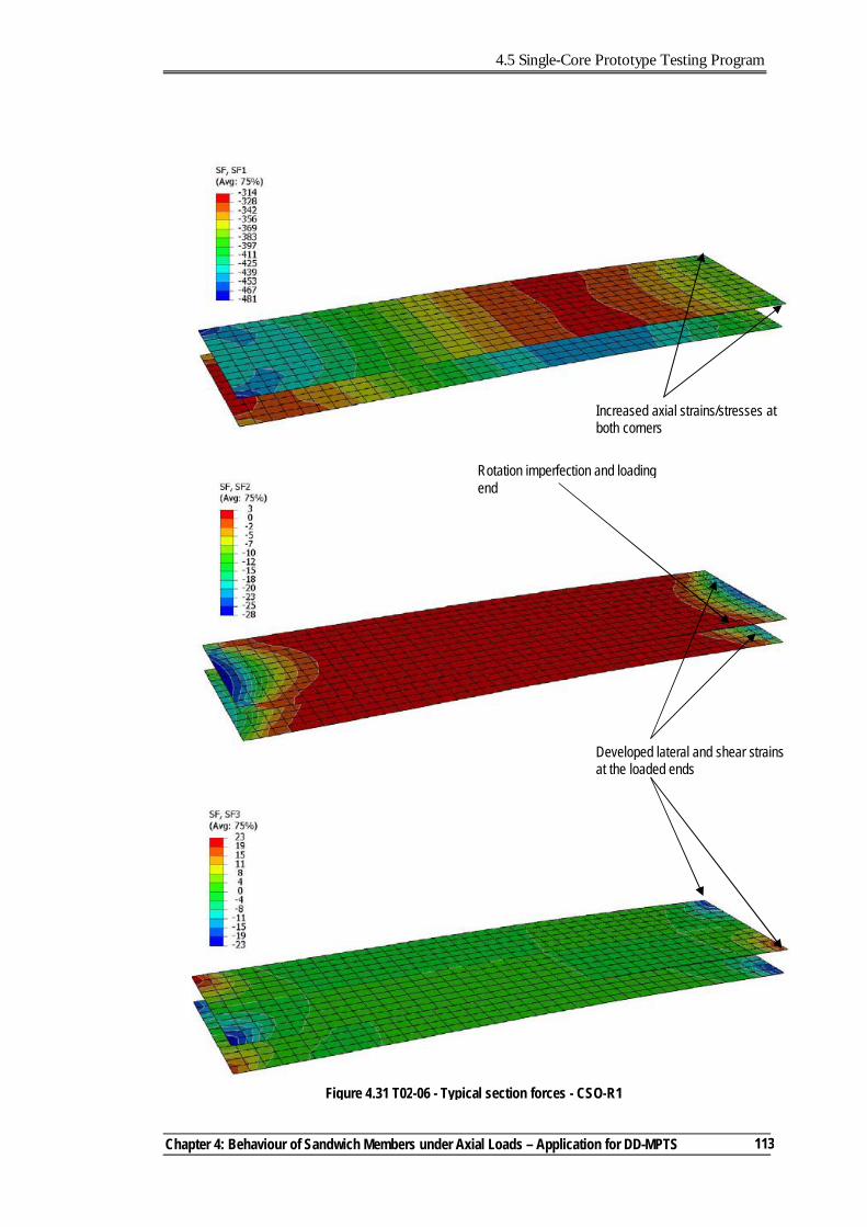
4.5 Single-Core Prototype Testing Program
Chapter 4: Behaviour of Sandwich Members under Axial Loads – Application for DD-MPTS
113
Developed lateral and shear strains at the loaded ends
Increased axial strains/stresses at both corners
Figure 4.31 T02-06 - Typical section forces - CSO-R1
Rotation imperfection and loading end
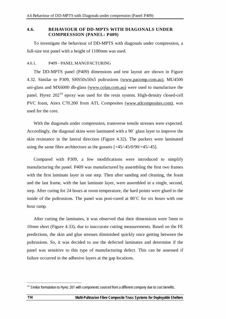
4.6 Behaviour of DD-MPTS with Diagonals under compression (Panel: P409)
Multi-Pultrusion Fibre Composite Truss Systems for Deployable Shelters
114
4.6. BEHAVIOUR OF DD-MPTS WITH DIAGONALS UNDER COMPRESSION (PANEL: P409)
To investigate the behaviour of DD-MPTS with diagonals under compression, a
full-size test panel with a height of 1100mm was used.
4.6.1. P409 - PANEL MANUFACTURING
The DD-MPTS panel (P409) dimensions and test layout are shown in Figure
4.32. Similar to P309, SHS50x50x5 pultrusions (www.pacomp.com.au), MU4500
uni-glass and MX6000 db-glass (www.colan.com.au) were used to manufacture the
panel. Hyrez 20214 epoxy was used for the resin system. High-density closed-cell
PVC foam, Airex C70.200 from ATL Composites (www.atlcomposites.com), was
used for the core.
With the diagonals under compression, transverse tensile stresses were expected.
Accordingly, the diagonal skins were laminated with a 90˚ glass layer to improve the
skin resistance in the lateral direction (Figure 4.32). The packers were laminated
using the same fibre architecture as the gussets [+45/-45/0/90/+45/-45].
Compared with P309, a few modifications were introduced to simplify
manufacturing the panel. P409 was manufactured by assembling the first two frames
with the first laminate layer in one step. Then after sanding and cleaning, the foam
and the last frame, with the last laminate layer, were assembled in a single, second,
step. After curing for 24 hours at room temperature, the hard points were glued to the
inside of the pultrusions. The panel was post-cured at 80˚C for six hours with one
hour ramp.
After cutting the laminates, it was observed that their dimensions were 5mm to
10mm short (Figure 4.33), due to inaccurate cutting measurements. Based on the FE
predictions, the skin and glue stresses diminished quickly once getting between the
pultrusions. So, it was decided to use the defected laminates and determine if the
panel was sensitive to this type of manufacturing defect. This can be assessed if
failure occurred in the adhesive layers at the gap locations.
14 Similar formulation to Hyrez 201 with components sourced from a different company due to cost benefits.
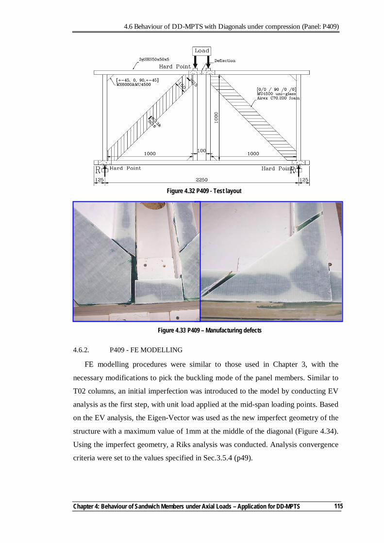
4.6 Behaviour of DD-MPTS with Diagonals under compression (Panel: P409)
Chapter 4: Behaviour of Sandwich Members under Axial Loads – Application for DD-MPTS
115
4.6.2. P409 - FE MODELLING
FE modelling procedures were similar to those used in Chapter 3, with the
necessary modifications to pick the buckling mode of the panel members. Similar to
T02 columns, an initial imperfection was introduced to the model by conducting EV
analysis as the first step, with unit load applied at the mid-span loading points. Based
on the EV analysis, the Eigen-Vector was used as the new imperfect geometry of the
structure with a maximum value of 1mm at the middle of the diagonal (Figure 4.34).
Using the imperfect geometry, a Riks analysis was conducted. Analysis convergence
criteria were set to the values specified in Sec.3.5.4 (p49).
Figure 4.32 P409 - Test layout
Figure 4.33 P409 – Manufacturing defects
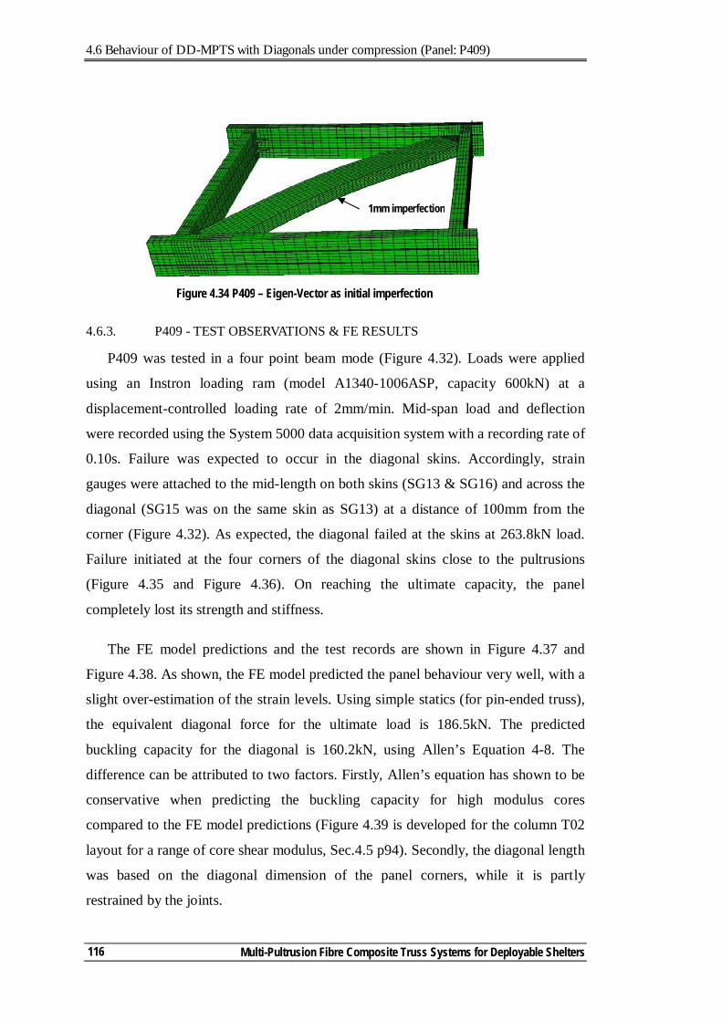
4.6 Behaviour of DD-MPTS with Diagonals under compression (Panel: P409)
Multi-Pultrusion Fibre Composite Truss Systems for Deployable Shelters
116
4.6.3. P409 - TEST OBSERVATIONS & FE RESULTS
P409 was tested in a four point beam mode (Figure 4.32). Loads were applied
using an Instron loading ram (model A1340-1006ASP, capacity 600kN) at a
displacement-controlled loading rate of 2mm/min. Mid-span load and deflection
were recorded using the System 5000 data acquisition system with a recording rate of
0.10s. Failure was expected to occur in the diagonal skins. Accordingly, strain
gauges were attached to the mid-length on both skins (SG13 & SG16) and across the
diagonal (SG15 was on the same skin as SG13) at a distance of 100mm from the
corner (Figure 4.32). As expected, the diagonal failed at the skins at 263.8kN load.
Failure initiated at the four corners of the diagonal skins close to the pultrusions
(Figure 4.35 and Figure 4.36). On reaching the ultimate capacity, the panel
completely lost its strength and stiffness.
The FE model predictions and the test records are shown in Figure 4.37 and
Figure 4.38. As shown, the FE model predicted the panel behaviour very well, with a
slight over-estimation of the strain levels. Using simple statics (for pin-ended truss),
the equivalent diagonal force for the ultimate load is 186.5kN. The predicted
buckling capacity for the diagonal is 160.2kN, using Allen’s Equation 4-8. The
difference can be attributed to two factors. Firstly, Allen’s equation has shown to be
conservative when predicting the buckling capacity for high modulus cores
compared to the FE model predictions (Figure 4.39 is developed for the column T02
layout for a range of core shear modulus, Sec.4.5 p94). Secondly, the diagonal length
was based on the diagonal dimension of the panel corners, while it is partly
restrained by the joints.
Figure 4.34 P409 – Eigen-Vector as initial imperfection
1mm imperfection
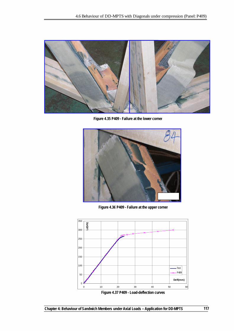
4.6 Behaviour of DD-MPTS with Diagonals under compression (Panel: P409)
Chapter 4: Behaviour of Sandwich Members under Axial Loads – Application for DD-MPTS
117
Figure 4.37 P409 - Load-deflection curves
0
50
100
150
200
250
300
350
0 10 20 30 40 50 60
Defl(mm)
Ld(k
N)
Test
P409
Figure 4.35 P409 - Failure at the lower corner
Figure 4.36 P409 - Failure at the upper corner
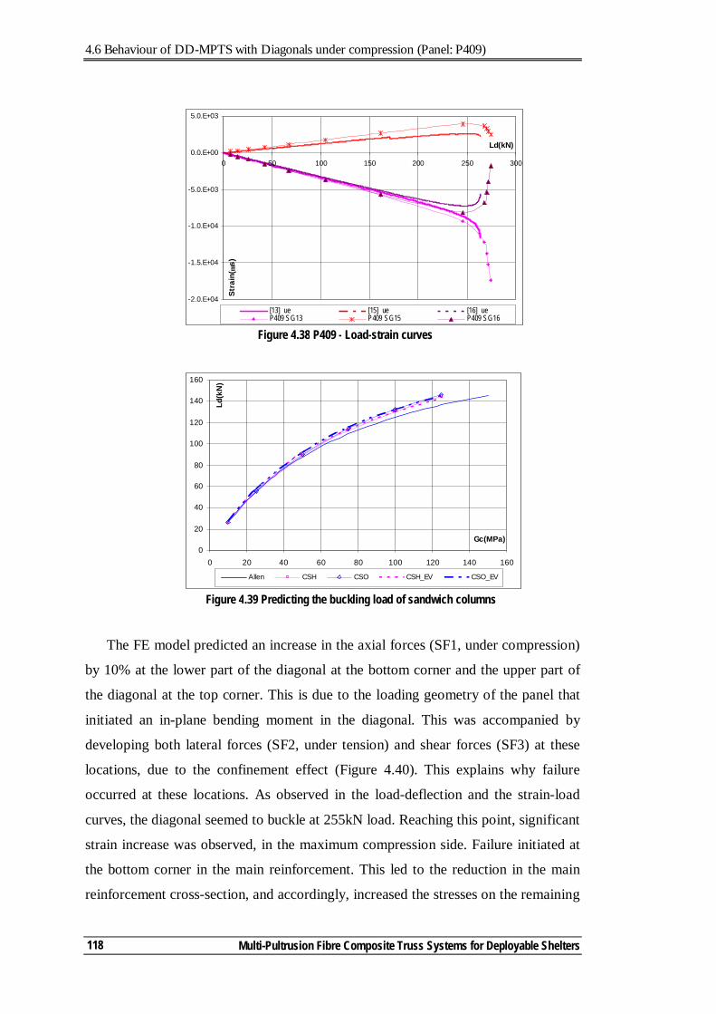
4.6 Behaviour of DD-MPTS with Diagonals under compression (Panel: P409)
Multi-Pultrusion Fibre Composite Truss Systems for Deployable Shelters
118
The FE model predicted an increase in the axial forces (SF1, under compression)
by 10% at the lower part of the diagonal at the bottom corner and the upper part of
the diagonal at the top corner. This is due to the loading geometry of the panel that
initiated an in-plane bending moment in the diagonal. This was accompanied by
developing both lateral forces (SF2, under tension) and shear forces (SF3) at these
locations, due to the confinement effect (Figure 4.40). This explains why failure
occurred at these locations. As observed in the load-deflection and the strain-load
curves, the diagonal seemed to buckle at 255kN load. Reaching this point, significant
strain increase was observed, in the maximum compression side. Failure initiated at
the bottom corner in the main reinforcement. This led to the reduction in the main
reinforcement cross-section, and accordingly, increased the stresses on the remaining
Figure 4.39 Predicting the buckling load of sandwich columns
0
20
40
60
80
100
120
140
160
0 20 40 60 80 100 120 140 160
Gc(MPa)
Ld(k
N)
Allen CSH CSO CSH_EV CSO_EV
Figure 4.38 P409 - Load-strain curves
-2.0.E+04
-1.5.E+04
-1.0.E+04
-5.0.E+03
0.0.E+00
5.0.E+03
0 50 100 150 200 250 300
Ld(kN)
Stra
in( µ
s)
[13] ue [15] ue [16] ueP409 SG13 P409 SG15 P409 SG16
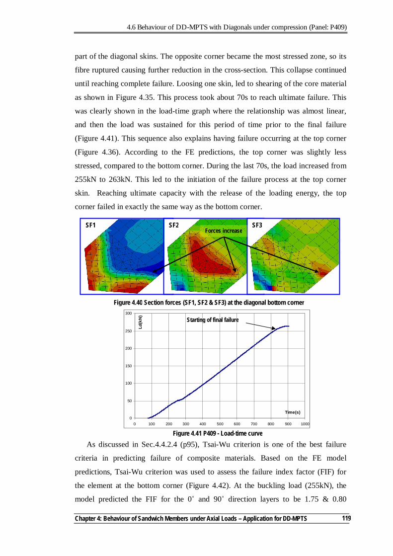
4.6 Behaviour of DD-MPTS with Diagonals under compression (Panel: P409)
Chapter 4: Behaviour of Sandwich Members under Axial Loads – Application for DD-MPTS
119
part of the diagonal skins. The opposite corner became the most stressed zone, so its
fibre ruptured causing further reduction in the cross-section. This collapse continued
until reaching complete failure. Loosing one skin, led to shearing of the core material
as shown in Figure 4.35. This process took about 70s to reach ultimate failure. This
was clearly shown in the load-time graph where the relationship was almost linear,
and then the load was sustained for this period of time prior to the final failure
(Figure 4.41). This sequence also explains having failure occurring at the top corner
(Figure 4.36). According to the FE predictions, the top corner was slightly less
stressed, compared to the bottom corner. During the last 70s, the load increased from
255kN to 263kN. This led to the initiation of the failure process at the top corner
skin. Reaching ultimate capacity with the release of the loading energy, the top
corner failed in exactly the same way as the bottom corner.
As discussed in Sec.4.4.2.4 (p95), Tsai-Wu criterion is one of the best failure
criteria in predicting failure of composite materials. Based on the FE model
predictions, Tsai-Wu criterion was used to assess the failure index factor (FIF) for
the element at the bottom corner (Figure 4.42). At the buckling load (255kN), the
model predicted the FIF for the 0˚ and 90˚ direction layers to be 1.75 & 0.80
0
50
100
150
200
250
300
0 100 200 300 400 500 600 700 800 900 1000
Time(s)
Ld(k
N)
Figure 4.41 P409 - Load-time curve
Starting of final failure
Figure 4.40 Section forces (SF1, SF2 & SF3) at the diagonal bottom corner
Forces increase SF1 SF2 SF3
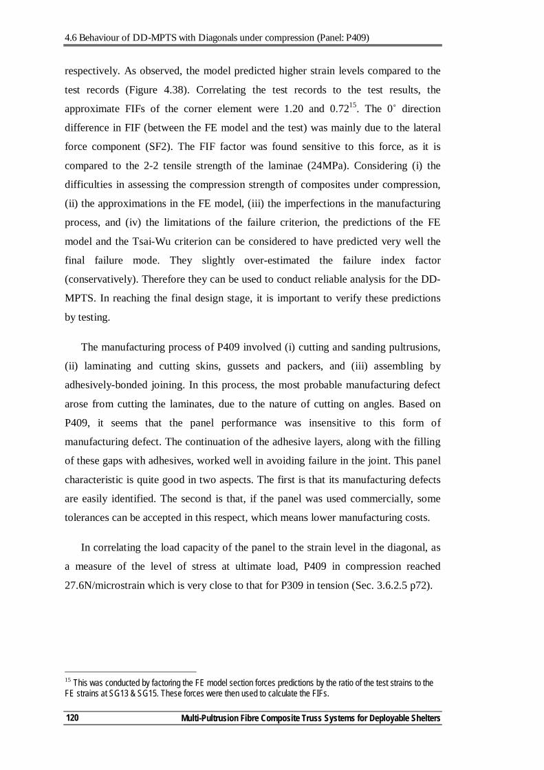
4.6 Behaviour of DD-MPTS with Diagonals under compression (Panel: P409)
Multi-Pultrusion Fibre Composite Truss Systems for Deployable Shelters
120
respectively. As observed, the model predicted higher strain levels compared to the
test records (Figure 4.38). Correlating the test records to the test results, the
approximate FIFs of the corner element were 1.20 and 0.7215. The 0˚ direction
difference in FIF (between the FE model and the test) was mainly due to the lateral
force component (SF2). The FIF factor was found sensitive to this force, as it is
compared to the 2-2 tensile strength of the laminae (24MPa). Considering (i) the
difficulties in assessing the compression strength of composites under compression,
(ii) the approximations in the FE model, (iii) the imperfections in the manufacturing
process, and (iv) the limitations of the failure criterion, the predictions of the FE
model and the Tsai-Wu criterion can be considered to have predicted very well the
final failure mode. They slightly over-estimated the failure index factor
(conservatively). Therefore they can be used to conduct reliable analysis for the DD-
MPTS. In reaching the final design stage, it is important to verify these predictions
by testing.
The manufacturing process of P409 involved (i) cutting and sanding pultrusions,
(ii) laminating and cutting skins, gussets and packers, and (iii) assembling by
adhesively-bonded joining. In this process, the most probable manufacturing defect
arose from cutting the laminates, due to the nature of cutting on angles. Based on
P409, it seems that the panel performance was insensitive to this form of
manufacturing defect. The continuation of the adhesive layers, along with the filling
of these gaps with adhesives, worked well in avoiding failure in the joint. This panel
characteristic is quite good in two aspects. The first is that its manufacturing defects
are easily identified. The second is that, if the panel was used commercially, some
tolerances can be accepted in this respect, which means lower manufacturing costs.
In correlating the load capacity of the panel to the strain level in the diagonal, as
a measure of the level of stress at ultimate load, P409 in compression reached
27.6N/microstrain which is very close to that for P309 in tension (Sec. 3.6.2.5 p72).
15 This was conducted by factoring the FE model section forces predictions by the ratio of the test strains to the FE strains at SG13 & SG15. These forces were then used to calculate the FIFs.
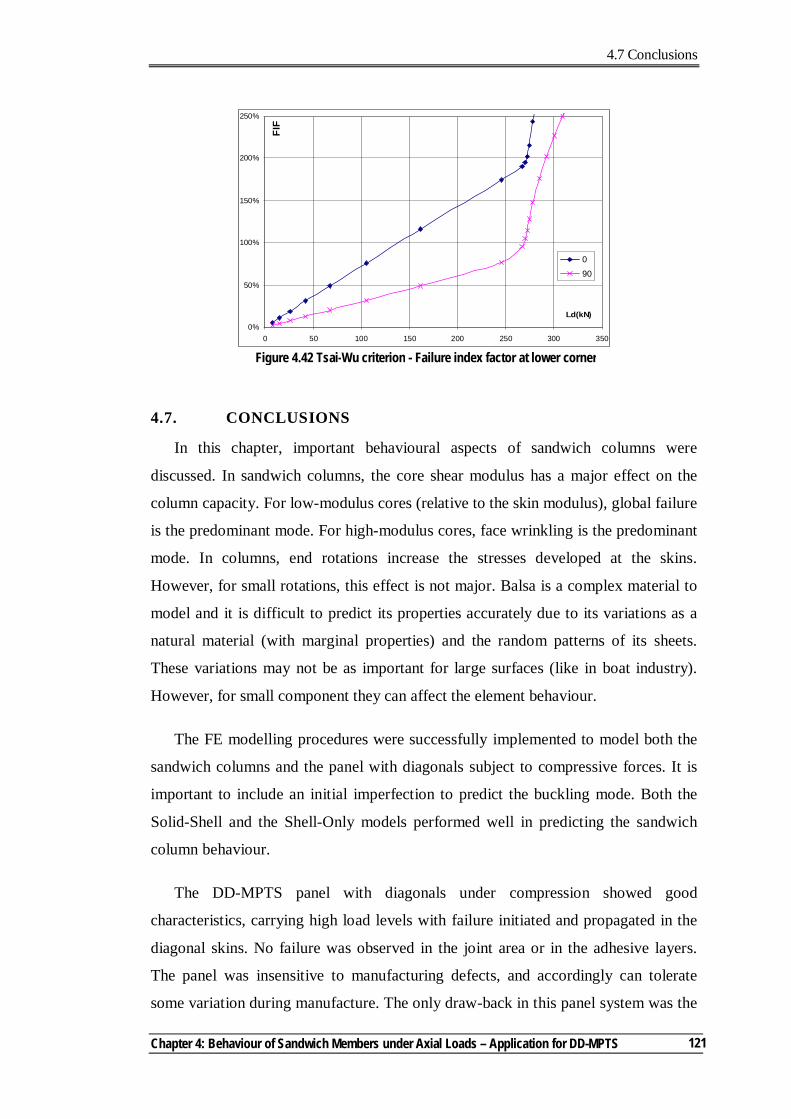
4.7 Conclusions
Chapter 4: Behaviour of Sandwich Members under Axial Loads – Application for DD-MPTS
121
4.7. CONCLUSIONS
In this chapter, important behavioural aspects of sandwich columns were
discussed. In sandwich columns, the core shear modulus has a major effect on the
column capacity. For low-modulus cores (relative to the skin modulus), global failure
is the predominant mode. For high-modulus cores, face wrinkling is the predominant
mode. In columns, end rotations increase the stresses developed at the skins.
However, for small rotations, this effect is not major. Balsa is a complex material to
model and it is difficult to predict its properties accurately due to its variations as a
natural material (with marginal properties) and the random patterns of its sheets.
These variations may not be as important for large surfaces (like in boat industry).
However, for small component they can affect the element behaviour.
The FE modelling procedures were successfully implemented to model both the
sandwich columns and the panel with diagonals subject to compressive forces. It is
important to include an initial imperfection to predict the buckling mode. Both the
Solid-Shell and the Shell-Only models performed well in predicting the sandwich
column behaviour.
The DD-MPTS panel with diagonals under compression showed good
characteristics, carrying high load levels with failure initiated and propagated in the
diagonal skins. No failure was observed in the joint area or in the adhesive layers.
The panel was insensitive to manufacturing defects, and accordingly can tolerate
some variation during manufacture. The only draw-back in this panel system was the
Figure 4.42 Tsai-Wu criterion - Failure index factor at lower corner
0%
50%
100%
150%
200%
250%
0 50 100 150 200 250 300 350
Ld(kN)
FIF
0
90
4.7 Conclusions
Multi-Pultrusion Fibre Composite Truss Systems for Deployable Shelters
122
sudden failure that led to losing all the panel stiffness and strength on reaching the
ultimate capacity. The panel behaviour was predicted very well by using the FE
modelling procedures. The use of Tsia-Wu failure criterion predicted conservatively
the final failure of the panel.
4.8. REFERENCES
Allen, H. G. (1969). Analysis and design of structural sandwich panels, Pergamon Press, Oxford.
Allen, H. G., and Feng, Z. (1997). Classification of structural sandwich panel behaviour. Mechanics of Sandwich Structures, Proceeding of the EUROMECH 360 Colloquium, A. Vautrin, ed., Kluwer Academic Publishers, Saint-Etienne, France, 1-12.
American Society for Testing and Materials. (2000). ASTM C393 : Standard Test Method for Core Shear Properties of Sandwich Constructions by Beam Flexure.
Anon. (1955). Materials, properties and design criteria Part II, sandwich construction for aircraft. MIL-HDBK-23, Department of the Air Force Research and Development, USA.
Argon, A. S. (1972). Fracture of composites. Treatise on Material Science and Technology, Academic Press, New York, 79-114.
ATL Composites Homepage. http://www.atlcomposites.com.au. Bazant, Z. P. (1971). A correlation study of incremental deformations and stability of
continuous bodies. ASME Journal of Applied Mechanics, 38, 919-928. Bazant, Z. P. (2003). Shear buckling of sandwich, fiber composite and lattice
columns, bearings, and helical springs: paradox resolved. ASME Journal of Applied Mechanics, 70, 75-83.
Bazant, Z. P., and Beghini, A. (2004). Sandwich buckling formulas and applicability of standard computational algorithm for finite strain. Composites Pt B, 35, 573-581.
Bazant, Z. P., and Cedolin, L. (1991). Stability of structures, Oxford University Press Inc, Oxford.
Bitzer, T. N. (1992). Recent honeycomb core developments. Second International Conference on Sandwich Construction, UK, 555-563.
Budiansky, B. (1983). Micromechanics. Computers and Structures, 16(1-4), 3-12. Butalia, T. S., and Wolfe, W. E. (2002). A strain-energy based failure criterion for
non-linear analysis of composite laminates subjected to bi-axial loading. Composites Science and Technology, 62, 1697-1710.
Colan Homepage. http://www.colan.com.au. Davies, J. M. (1997). Design criteria for sandwich panels for building construction.
4.8 References
Chapter 4: Behaviour of Sandwich Members under Axial Loads – Application for DD-MPTS
123
ASME Aerospace Division, Structures and Materials Committee, ASME-AD_Vol 55, New York, 273-284.
Davila, C. G., Camanho, P. P., and Rose, C. A. (2005). Failure criteria for FRP laminates. Journal of Composite Materials, 39(4), 323-345.
Diab Homepage. http://www.diabgroup.com. Dreher, G. (1992). Stability failure of sandwich structures. Sandwich Constructions 2
- Proceedings of the Second International Conference on Sandwich Construction, Gainesville, Florida, USA.
Engesser, F. (1891). Die knickfestigkeit gerader stabe. Zentralblatt des Bauverwaltung, 11, 483-486.
Euler, L. (1744). De curvis elasticis. Burges, Lausanne, Switzerland. Export911 Homepage. http://www.export911.com.
Fairbairn, W. (1849). An account of the construction of the Britannia and Conway tubular bridges, John Weale, London.
Fleck, N. A. (1997). Compressive failure of fibre composites. Advances in Applied Mechanics, 33, 43-117.
Fleck, N. A., and Sridhar, I. (2002). End compression of sandwich columns. Composites Pt A, 33, 353-359.
Gdoutos, E. E., Daniel, I. M., and Wang, K.-A. (2003). Compression facing wrinkling of composite sandwich structures. Mechanics of Materials, 35, 511-522.
Gere, J. M., and Timoshenko, S. P. (1990). Mechanics of materials, PWS-KENT Publishing Company, Boston.
Gotsis, P. K., Chamis, C. C., and Minnetyan, L. (1998). Prediction of composite laminate fracture: micromechanics and progressive fracture. Composites Science and Technology, 58, 1137-1149.
Gotsis, P. K., Chamis, C. C., and Minnetyan, L. (2002). Application of progressive fracture analysis for predicting failure envelopes and stress-strain behaviors of composite laminates: a comparison with experimental results. Composites Science and Technology, 62, 1545-1559.
Haringx, J. A. (1948). On highly compressible helical springs and rubber rods and their application for vibration-free mounting. Philips Research Report Vol.3, Eindhoven.
Hibbitt, Karlsson & Sorensen Inc. (2004a). ABAQUS Analysis user's manual. Hibbitt, Karlsson & Sorensen Inc. (2004b). ABAQUS Theory manual. Hinton, M. J., Kaddour, A. S., and Soden, P. D. (2002a). Evaluation of failure
prediction in composite laminates: background to part 'B' of the exercise. Composites Science and Technology, 62, 1481-1488.
Hinton, M. J., Kaddour, A. S., and Soden, P. D. (2002b). A comparison of the predictive capabilities of current failure theories for composite laminates judged against experimental evidence. Composites Science and Technology, 62, 1725-1797.
4.8 References
Multi-Pultrusion Fibre Composite Truss Systems for Deployable Shelters
124
Hinton, M. J., and Soden, P. D. (1998). Predicting failure in composite laminates: the background to the exercise. Composites Science and Technology, 58, 1001-1010.
Hoff, N. J., and Mautber, S. E. (1945). The buckling of sandwich type panels. Journal of Aeronautical Sciences, 12(3), 285-297.
Huang, H., and Kardomateas, G. A. (2002). Buckling and initial postbuckling behavior of sandwich beams including transverse shear. AIAA Journal, 40(11), 2331-2335.
Humphreys, M. F., Van Erp, G. M., and Tranberg, C. (1999). The structural behaviour of monocoque fibre composite truss joints. Advanced Composite Letters, 8(4), 173-180.
Huntsman home page. http://www.huntsman.ivt.com.au. Karbhari , V. (1997). Application of composite materials to the renewal of twenty-
first century infrastructure. Eleventh International Conference on Composite Materials, Gold Coast, Australia.
Kardomateas, G. A., and Simitses, G. J. (2004). Comparative studies on the buckling of isotropic, orthotropic and sandwich columns. Mechanics of Advanced Materials and Structures, 11, 309-327.
Kuraishi, A., Tsai, S. W., and Liu, K. K. S. (2002). A progressive quadratic failure criterion - part B. Composites Science and Technology, 62, 1683-1695.
Librescu, L., and Hause, T. (2000). Recent developments in the modeling and behavior of advanced sandwich constructions: a survey. Composite Structures, 48, 1-17.
Liu, K. S., and Tsai, S. W. (1998). A progressive quadratic failure criterion for a laminate. Composites Science and Technology, 58, 1023-1032.
Mamalis, A. G., Manolakos, D. E., Ioannidis, M. B., and Papapostolou, D. P. (2005). On the crushing response of composite sandwich panels subjected to edgewise compression: experimental. Composite Structures, 71, 246-257.
Marguerre, K. (1944). The optimum buckling load of a flexibly supported plate composed of two sheets joined by a light weight filler, when under longitudinal compression. ZWB UM 1360/2, Deutsche Vierteljahrsschrist für Literalurwissenschaft und Giests Geschichte, D V L.
Pacific Composites Homepage. http://http://www.pacomp.com.au/.
Piggott, M. R. (1981). A theoretical framework for the compressive failure of aligned fibre composites. Journal of Material Science, 16, 2837-2845.
Piggott, M. R., and Harris, B. (1980). Compression strength of carbon, glass and Kevlar-49 fibre reinforced polyester resins. Journal of Material Science, 15, 2523-2538.
Plantema, J. F. (1966). Sandwich construction, Wiley, New York.
Puck, A., and Schurmann, H. (1998). Failure analysis of FRP laminates by means of physically based phenomenological models. Composites Science and Technology, 58, 1045-1067.
4.8 References
Chapter 4: Behaviour of Sandwich Members under Axial Loads – Application for DD-MPTS
125
Puck, A., and Schurmann, H. (2002). Failure analysis of FRP laminates by means of physically based phenomenological models. Composites Science and Technology, 62, 1633-1662.
Rheinfrank, G. B., and Norman, W. A. (1944). Molded glass fiber sandwich fuselage for BT-15 airplane. Army Air Corps Technical Report No 5159, USA.
Robert Scherer Homepage. http://www.bobscherer.com.
Soden, P. D., Hinton, M. J., and Kaddour, A. S. (1998). Comparison of the predictive capabilities of current failure theories for composite laminates. Composites Science and Technology, 58, 1225-1254.
Sun, C. T., and Tao, J. (1998). The prediction of failure envelopes and stress-strain behavior of composite laminates. Composites Science and Technology, 58, 1125-1136.
Sun, C. T., Tao, J., and Kaddour, A. S. (2002). The prediction of failure envelopes and stress-strain behavior of composite laminates: comparison with experimental results. Composites Science and Technology, 62, 1673-1682.
Vinson, J. R. (1999). The behavior of sandwich structures of isotropic and composite materials, Technomic Publishing Company, Lancaster, Pennsylvania.
Vonach, W. K., and Rammerstorfer, F. (2000). The effect of in-plane core stiffness on the wrinkling behaviour of thick sandwiches. Acta Metallurgica, 141, 1-10.
Wikipedia home page. http://en.wikipedia.org/wiki/Beechcraft_Starship. Wolfe, W. E., and Butalia, T. S. (1998). A strain-energy based failure criterion for
non-linear analysis of composite laminates subjected to bi-axial loading. Composites Science and Technology, 58, 1107-1124.
Zinoviev, P. A., Grigoriev, S. V., Lebedeva, O. V., and Tairova, L. P. (1998). The strength of multilayered composites under a plane stress state. Composites Science and Technology, 58, 1209-1223.
Zinoviev, P. A., Lebedeva, O. V., and Tairova, L. P. (2002). A coupled analysis of experimental and theoritical results of numerical predictions and experimental observations for symmetric composite laminates. Composites Science and Technology, 62, 1711-1723.

Chapter 5 Notations
Multi-Pultrusion Fibre Composite Truss Systems for Deployable Shelters
126
Chapter 5 Notations
SF1 Longitudinal section forces (in 1-1 direction, N/mm)
SF2 Transverse section forces (in 2-2 direction, N/mm)
U3 Out-of-plane displacement (mm)
Nt1 Integrated sectional axial forces (SF1) on the shell element (kN)
SM1 Section bending moments in 1-1 direction (Nmm/mm)
SM2 Section bending moments in 2-2 direction (Nmm/mm)
SF3 Shear section forces (in the 1-2 plane, N/mm)
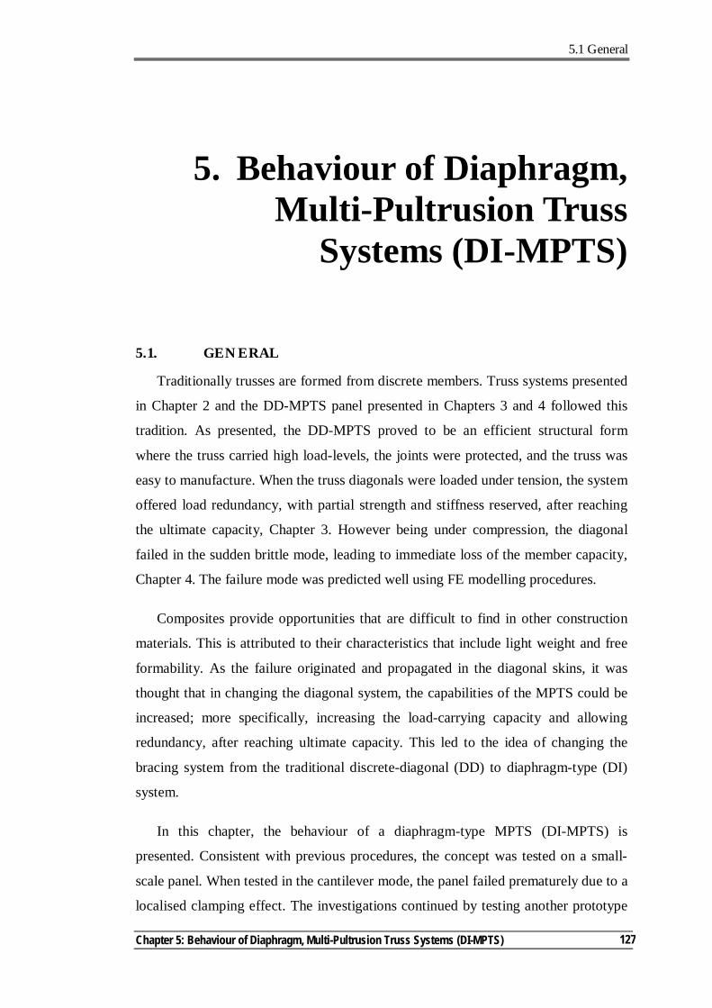
5.1 General
Chapter 5: Behaviour of Diaphragm, Multi-Pultrusion Truss Systems (DI-MPTS)
127
5. Behaviour of Diaphragm, Multi-Pultrusion Truss
Systems (DI-MPTS)
5.1. GENERAL
Traditionally trusses are formed from discrete members. Truss systems presented
in Chapter 2 and the DD-MPTS panel presented in Chapters 3 and 4 followed this
tradition. As presented, the DD-MPTS proved to be an efficient structural form
where the truss carried high load-levels, the joints were protected, and the truss was
easy to manufacture. When the truss diagonals were loaded under tension, the system
offered load redundancy, with partial strength and stiffness reserved, after reaching
the ultimate capacity, Chapter 3. However being under compression, the diagonal
failed in the sudden brittle mode, leading to immediate loss of the member capacity,
Chapter 4. The failure mode was predicted well using FE modelling procedures.
Composites provide opportunities that are difficult to find in other construction
materials. This is attributed to their characteristics that include light weight and free
formability. As the failure originated and propagated in the diagonal skins, it was
thought that in changing the diagonal system, the capabilities of the MPTS could be
increased; more specifically, increasing the load-carrying capacity and allowing
redundancy, after reaching ultimate capacity. This led to the idea of changing the
bracing system from the traditional discrete-diagonal (DD) to diaphragm-type (DI)
system.
In this chapter, the behaviour of a diaphragm-type MPTS (DI-MPTS) is
presented. Consistent with previous procedures, the concept was tested on a small-
scale panel. When tested in the cantilever mode, the panel failed prematurely due to a
localised clamping effect. The investigations continued by testing another prototype
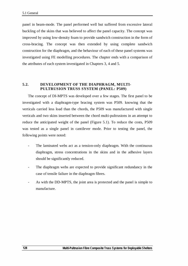
5.1 General
Multi-Pultrusion Fibre Composite Truss Systems for Deployable Shelters
128
panel in beam-mode. The panel performed well but suffered from excessive lateral
buckling of the skins that was believed to affect the panel capacity. The concept was
improved by using low-density foam to provide sandwich construction in the form of
cross-bracing. The concept was then extended by using complete sandwich
construction for the diaphragm, and the behaviour of each of these panel systems was
investigated using FE modelling procedures. The chapter ends with a comparison of
the attributes of each system investigated in Chapters 3, 4 and 5.
5.2. DEVELOPMENT OF THE DIAPHRAGM, MULTI-PULTRUSION TRUSS SYSTEM (PANEL: P509)
The concept of DI-MPTS was developed over a few stages. The first panel to be
investigated with a diaphragm-type bracing system was P509. knowing that the
verticals carried less load than the chords, the P509 was manufactured with single
verticals and two skins inserted between the chord multi-pultrusions in an attempt to
reduce the anticipated weight of the panel (Figure 5.1). To reduce the costs, P509
was tested as a single panel in cantilever mode. Prior to testing the panel, the
following points were noted:
- The laminated webs act as a tension-only diaphragm. With the continuous
diaphragm, stress concentrations in the skins and in the adhesive layers
should be significantly reduced.
- The diaphragm webs are expected to provide significant redundancy in the
case of tensile failure in the diaphragm fibres.
- As with the DD-MPTS, the joint area is protected and the panel is simple to
manufacture.
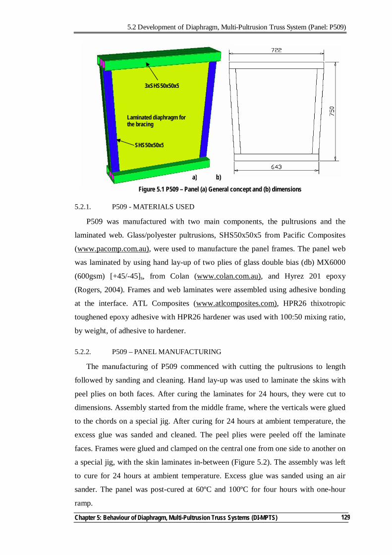
5.2 Development of Diaphragm, Multi-Pultrusion Truss System (Panel: P509)
Chapter 5: Behaviour of Diaphragm, Multi-Pultrusion Truss Systems (DI-MPTS)
129
5.2.1. P509 - MATERIALS USED
P509 was manufactured with two main components, the pultrusions and the
laminated web. Glass/polyester pultrusions, SHS50x50x5 from Pacific Composites
(www.pacomp.com.au), were used to manufacture the panel frames. The panel web
was laminated by using hand lay-up of two plies of glass double bias (db) MX6000
(600gsm) [+45/-45]s, from Colan (www.colan.com.au), and Hyrez 201 epoxy
(Rogers, 2004). Frames and web laminates were assembled using adhesive bonding
at the interface. ATL Composites (www.atlcomposites.com), HPR26 thixotropic
toughened epoxy adhesive with HPR26 hardener was used with 100:50 mixing ratio,
by weight, of adhesive to hardener.
5.2.2. P509 – PANEL MANUFACTURING
The manufacturing of P509 commenced with cutting the pultrusions to length
followed by sanding and cleaning. Hand lay-up was used to laminate the skins with
peel plies on both faces. After curing the laminates for 24 hours, they were cut to
dimensions. Assembly started from the middle frame, where the verticals were glued
to the chords on a special jig. After curing for 24 hours at ambient temperature, the
excess glue was sanded and cleaned. The peel plies were peeled off the laminate
faces. Frames were glued and clamped on the central one from one side to another on
a special jig, with the skin laminates in-between (Figure 5.2). The assembly was left
to cure for 24 hours at ambient temperature. Excess glue was sanded using an air
sander. The panel was post-cured at 60ºC and 100ºC for four hours with one-hour
ramp.
Figure 5.1 P509 – Panel (a) General concept and (b) dimensions
Laminated diaphragm for the bracing
3xSHS50x50x5
SHS50x50x5
a) b)
5.2 Development of the Diaphragm, Multi-pultrusion Truss System (Panel: P509)
Multi-Pultrusion Fibre Composite Truss Systems for Deployable Shelters
130
5.2.3. P509 - TEST RESULTS AND EVALUATION
P509 was tested in a cantilever mode. It was placed between two brackets
attached to a steel loading frame (Figure 5.3). Loads were applied using a manually-
operated hydraulic jack of 300kN capacity. Due to the horizontal component of the
load, the panel was laterally clamped to the testing frame. Both the load and
deflections were recorded at the cantilever end of the panel.
The load-deflection curve (Figure 5.4) suggested that at load level of 16.6kN,
significant reduction in stiffness occurred. This was attributed to the buckling of the
web (Figure 5.5). With further load application, the panel continuously lost stiffness,
yet to a lesser extent, when compared with pre-buckling/post-buckling change. This
is shown by the slopes of the straight line segments of the fitted curve (Figure 5.4).
Figure 5.2 P509 – Panel during assembly
Figure 5.3 P509 - Test layout
Load/Displacement
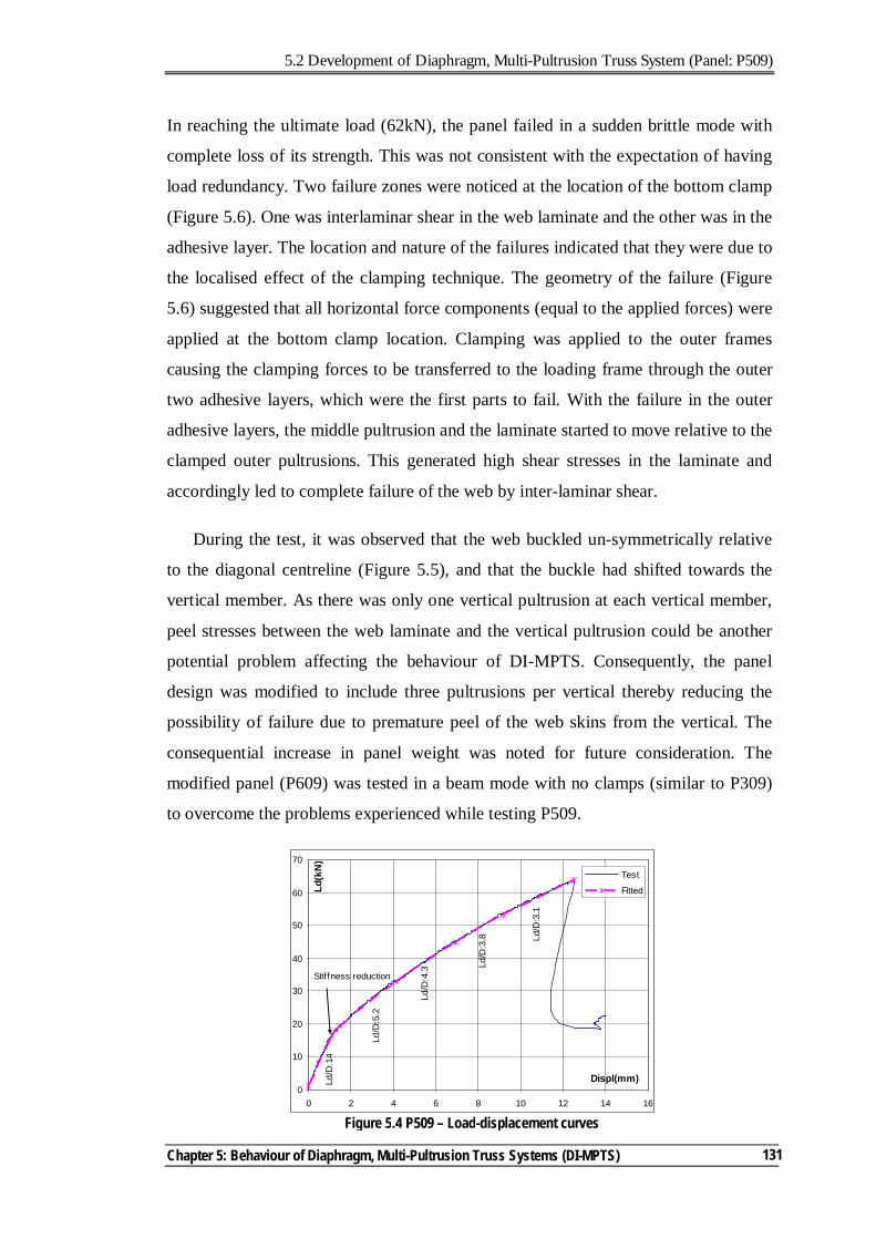
5.2 Development of Diaphragm, Multi-Pultrusion Truss System (Panel: P509)
Chapter 5: Behaviour of Diaphragm, Multi-Pultrusion Truss Systems (DI-MPTS)
131
In reaching the ultimate load (62kN), the panel failed in a sudden brittle mode with
complete loss of its strength. This was not consistent with the expectation of having
load redundancy. Two failure zones were noticed at the location of the bottom clamp
(Figure 5.6). One was interlaminar shear in the web laminate and the other was in the
adhesive layer. The location and nature of the failures indicated that they were due to
the localised effect of the clamping technique. The geometry of the failure (Figure
5.6) suggested that all horizontal force components (equal to the applied forces) were
applied at the bottom clamp location. Clamping was applied to the outer frames
causing the clamping forces to be transferred to the loading frame through the outer
two adhesive layers, which were the first parts to fail. With the failure in the outer
adhesive layers, the middle pultrusion and the laminate started to move relative to the
clamped outer pultrusions. This generated high shear stresses in the laminate and
accordingly led to complete failure of the web by inter-laminar shear.
During the test, it was observed that the web buckled un-symmetrically relative
to the diagonal centreline (Figure 5.5), and that the buckle had shifted towards the
vertical member. As there was only one vertical pultrusion at each vertical member,
peel stresses between the web laminate and the vertical pultrusion could be another
potential problem affecting the behaviour of DI-MPTS. Consequently, the panel
design was modified to include three pultrusions per vertical thereby reducing the
possibility of failure due to premature peel of the web skins from the vertical. The
consequential increase in panel weight was noted for future consideration. The
modified panel (P609) was tested in a beam mode with no clamps (similar to P309)
to overcome the problems experienced while testing P509.
Figure 5.4 P509 – Load-displacement curves
0
10
20
30
40
50
60
70
0 2 4 6 8 10 12 14 16
Displ(mm)
Ld(k
N)
Test
Fitted
Stiffness reduction
Ld/D
:14
Ld/D
:5.2
Ld/D
:4.3 Ld
/D:3
.8 Ld/D
:3.1
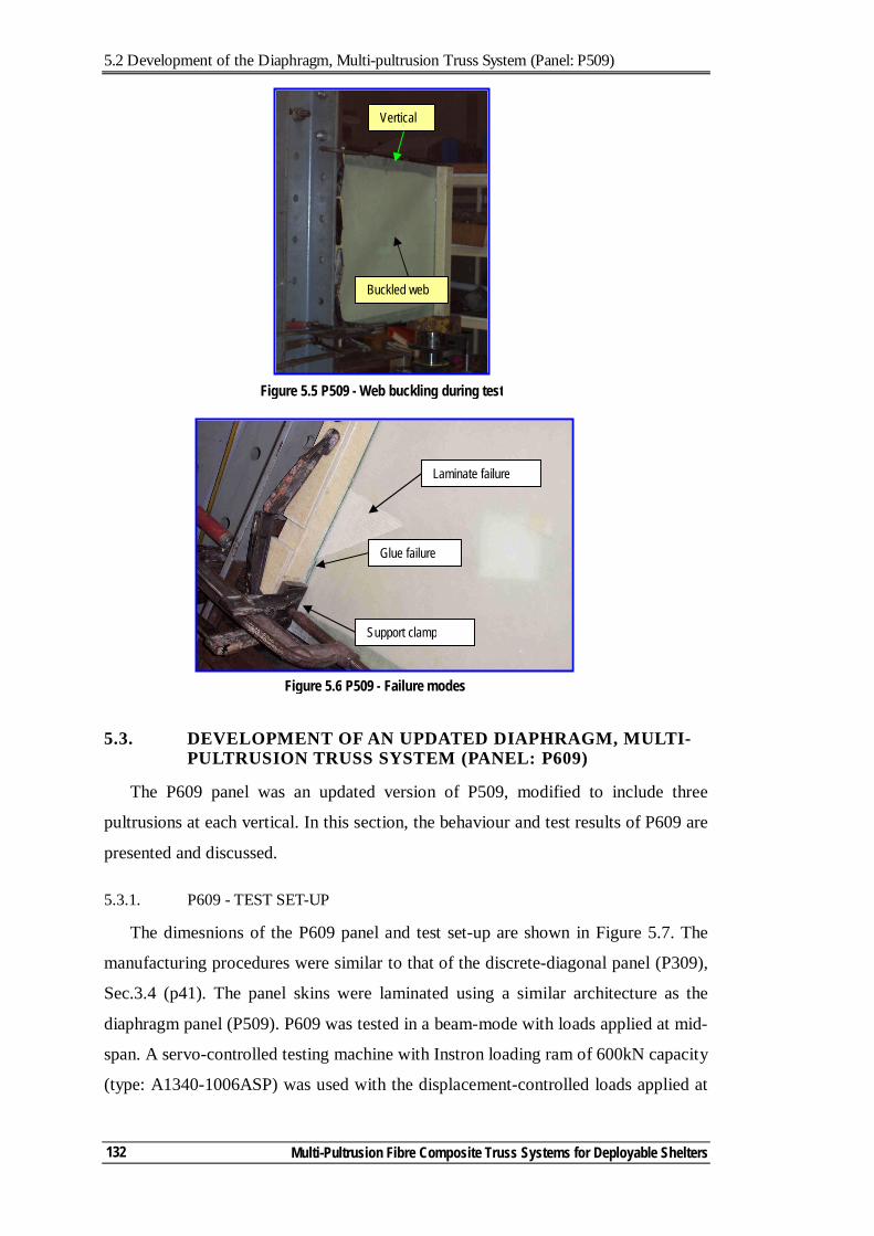
5.2 Development of the Diaphragm, Multi-pultrusion Truss System (Panel: P509)
Multi-Pultrusion Fibre Composite Truss Systems for Deployable Shelters
132
5.3. DEVELOPMENT OF AN UPDATED DIAPHRAGM, MULTI-PULTRUSION TRUSS SYSTEM (PANEL: P609)
The P609 panel was an updated version of P509, modified to include three
pultrusions at each vertical. In this section, the behaviour and test results of P609 are
presented and discussed.
5.3.1. P609 - TEST SET-UP
The dimesnions of the P609 panel and test set-up are shown in Figure 5.7. The
manufacturing procedures were similar to that of the discrete-diagonal panel (P309),
Sec.3.4 (p41). The panel skins were laminated using a similar architecture as the
diaphragm panel (P509). P609 was tested in a beam-mode with loads applied at mid-
span. A servo-controlled testing machine with Instron loading ram of 600kN capacity
(type: A1340-1006ASP) was used with the displacement-controlled loads applied at
Laminate failure
Support clamp
Glue failure
Figure 5.6 P509 - Failure modes
Figure 5.5 P509 - Web buckling during test
Vertical
Buckled web
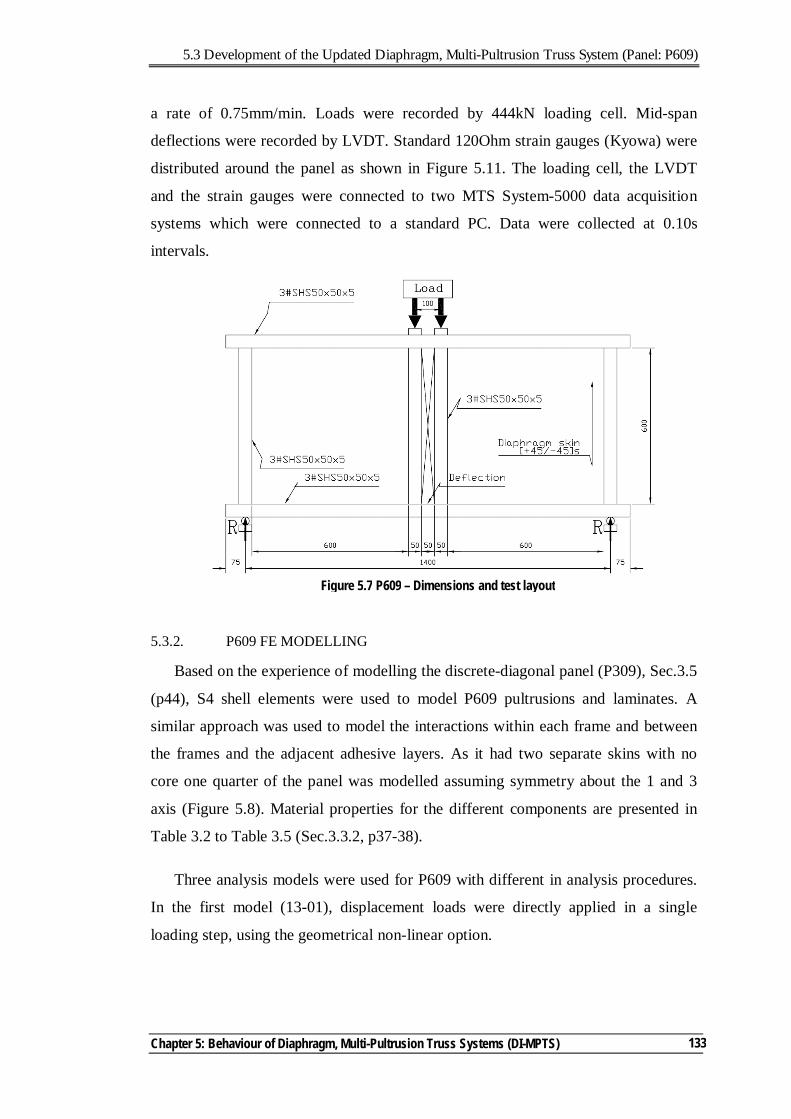
5.3 Development of the Updated Diaphragm, Multi-Pultrusion Truss System (Panel: P609)
Chapter 5: Behaviour of Diaphragm, Multi-Pultrusion Truss Systems (DI-MPTS)
133
a rate of 0.75mm/min. Loads were recorded by 444kN loading cell. Mid-span
deflections were recorded by LVDT. Standard 120Ohm strain gauges (Kyowa) were
distributed around the panel as shown in Figure 5.11. The loading cell, the LVDT
and the strain gauges were connected to two MTS System-5000 data acquisition
systems which were connected to a standard PC. Data were collected at 0.10s
intervals.
5.3.2. P609 FE MODELLING
Based on the experience of modelling the discrete-diagonal panel (P309), Sec.3.5
(p44), S4 shell elements were used to model P609 pultrusions and laminates. A
similar approach was used to model the interactions within each frame and between
the frames and the adjacent adhesive layers. As it had two separate skins with no
core one quarter of the panel was modelled assuming symmetry about the 1 and 3
axis (Figure 5.8). Material properties for the different components are presented in
Table 3.2 to Table 3.5 (Sec.3.3.2, p37-38).
Three analysis models were used for P609 with different in analysis procedures.
In the first model (13-01), displacement loads were directly applied in a single
loading step, using the geometrical non-linear option.
Figure 5.7 P609 – Dimensions and test layout
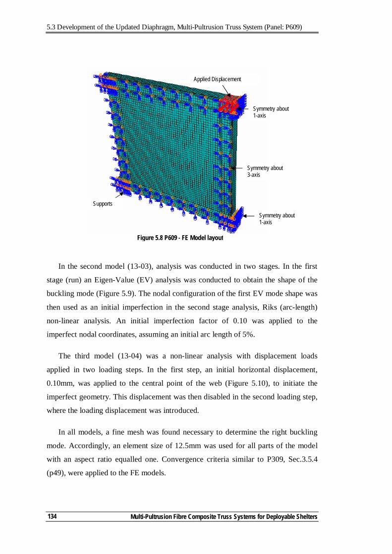
5.3 Development of the Updated Diaphragm, Multi-Pultrusion Truss System (Panel: P609)
Multi-Pultrusion Fibre Composite Truss Systems for Deployable Shelters
134
In the second model (13-03), analysis was conducted in two stages. In the first
stage (run) an Eigen-Value (EV) analysis was conducted to obtain the shape of the
buckling mode (Figure 5.9). The nodal configuration of the first EV mode shape was
then used as an initial imperfection in the second stage analysis, Riks (arc-length)
non-linear analysis. An initial imperfection factor of 0.10 was applied to the
imperfect nodal coordinates, assuming an initial arc length of 5%.
The third model (13-04) was a non-linear analysis with displacement loads
applied in two loading steps. In the first step, an initial horizontal displacement,
0.10mm, was applied to the central point of the web (Figure 5.10), to initiate the
imperfect geometry. This displacement was then disabled in the second loading step,
where the loading displacement was introduced.
In all models, a fine mesh was found necessary to determine the right buckling
mode. Accordingly, an element size of 12.5mm was used for all parts of the model
with an aspect ratio equalled one. Convergence criteria similar to P309, Sec.3.5.4
(p49), were applied to the FE models.
Supports
Symmetry about 1-axis
Symmetry about 3-axis
Applied Displacement
Symmetry about 1-axis
Figure 5.8 P609 - FE Model layout
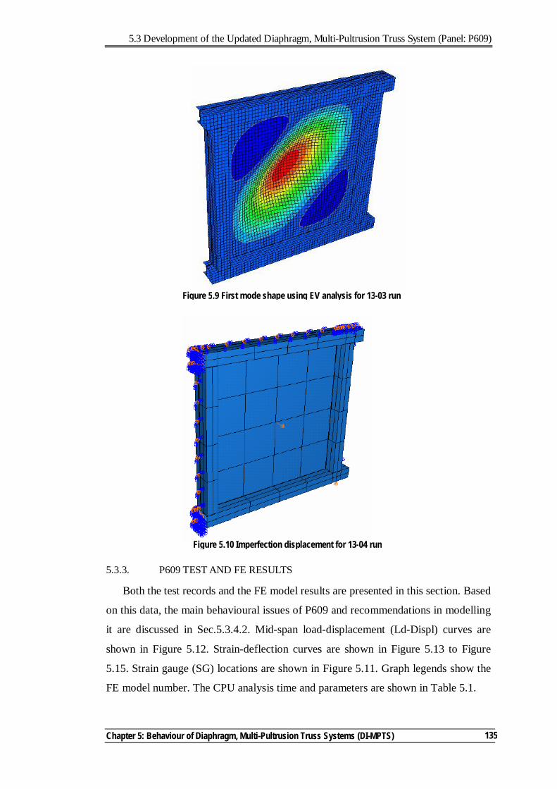
5.3 Development of the Updated Diaphragm, Multi-Pultrusion Truss System (Panel: P609)
Chapter 5: Behaviour of Diaphragm, Multi-Pultrusion Truss Systems (DI-MPTS)
135
5.3.3. P609 TEST AND FE RESULTS
Both the test records and the FE model results are presented in this section. Based
on this data, the main behavioural issues of P609 and recommendations in modelling
it are discussed in Sec.5.3.4.2. Mid-span load-displacement (Ld-Displ) curves are
shown in Figure 5.12. Strain-deflection curves are shown in Figure 5.13 to Figure
5.15. Strain gauge (SG) locations are shown in Figure 5.11. Graph legends show the
FE model number. The CPU analysis time and parameters are shown in Table 5.1.
Figure 5.10 Imperfection displacement for 13-04 run
Figure 5.9 First mode shape using EV analysis for 13-03 run
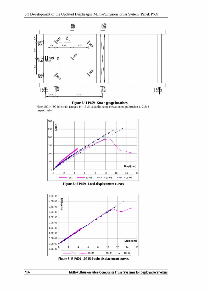
5.3 Development of the Updated Diaphragm, Multi-Pultrusion Truss System (Panel: P609)
Multi-Pultrusion Fibre Composite Truss Systems for Deployable Shelters
136
Figure 5.13 P609 - SG15 Strain-displacement curves
-5.0E+02
0.0E+00
5.0E+02
1.0E+03
1.5E+03
2.0E+03
2.5E+03
3.0E+03
3.5E+03
4.0E+03
4.5E+03
0 2 4 6 8 10 12 14 16
Displ(mm)
Stra
in( µ
s)
Test 13-01 13-03 13-04
Figure 5.12 P609 - Load-displacement curves
0
50
100
150
200
250
300
0 2 4 6 8 10 12 14 16
Displ(mm)
Ld(k
N)
Test 13-01 13-03 13-04
Figure 5.11 P609 - Strain gauge locations Note: SG14-SG16: strain gauges 14, 15 & 16 at the same elevation on pultrusion 1, 2 & 3 respectively
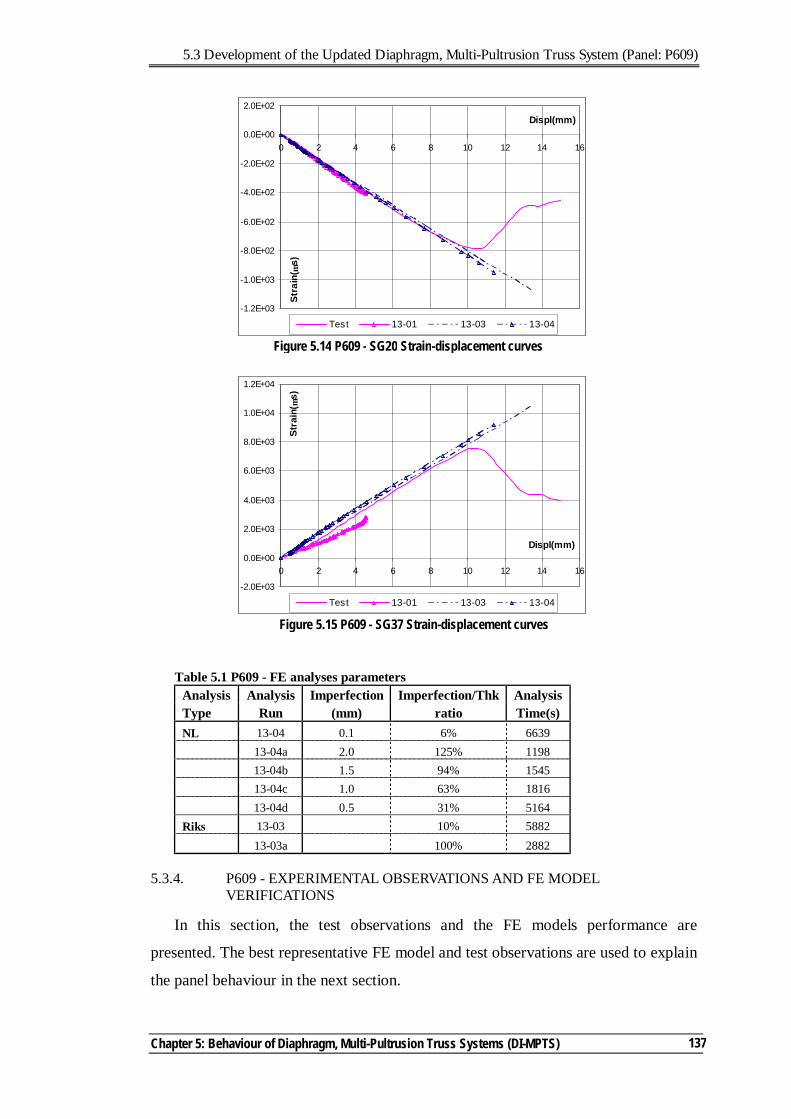
5.3 Development of the Updated Diaphragm, Multi-Pultrusion Truss System (Panel: P609)
Chapter 5: Behaviour of Diaphragm, Multi-Pultrusion Truss Systems (DI-MPTS)
137
Table 5.1 P609 - FE analyses parameters Analysis Analysis Imperfection Imperfection/Thk Analysis Type Run (mm) ratio Time(s) NL 13-04 0.1 6% 6639 13-04a 2.0 125% 1198 13-04b 1.5 94% 1545 13-04c 1.0 63% 1816 13-04d 0.5 31% 5164 Riks 13-03 10% 5882 13-03a 100% 2882
5.3.4. P609 - EXPERIMENTAL OBSERVATIONS AND FE MODEL VERIFICATIONS
In this section, the test observations and the FE models performance are
presented. The best representative FE model and test observations are used to explain
the panel behaviour in the next section.
Figure 5.14 P609 - SG20 Strain-displacement curves
-1.2E+03
-1.0E+03
-8.0E+02
-6.0E+02
-4.0E+02
-2.0E+02
0.0E+00
2.0E+02
0 2 4 6 8 10 12 14 16
Displ(mm)
Stra
in( µ
s)
Test 13-01 13-03 13-04
Figure 5.15 P609 - SG37 Strain-displacement curves
-2.0E+03
0.0E+00
2.0E+03
4.0E+03
6.0E+03
8.0E+03
1.0E+04
1.2E+04
0 2 4 6 8 10 12 14 16
Displ(mm)
Stra
in( µ
s)
Test 13-01 13-03 13-04
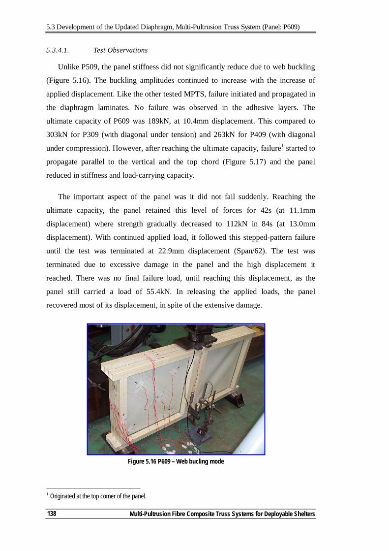
5.3 Development of the Updated Diaphragm, Multi-Pultrusion Truss System (Panel: P609)
Multi-Pultrusion Fibre Composite Truss Systems for Deployable Shelters
138
5.3.4.1. Test Observations
Unlike P509, the panel stiffness did not significantly reduce due to web buckling
(Figure 5.16). The buckling amplitudes continued to increase with the increase of
applied displacement. Like the other tested MPTS, failure initiated and propagated in
the diaphragm laminates. No failure was observed in the adhesive layers. The
ultimate capacity of P609 was 189kN, at 10.4mm displacement. This compared to
303kN for P309 (with diagonal under tension) and 263kN for P409 (with diagonal
under compression). However, after reaching the ultimate capacity, failure1 started to
propagate parallel to the vertical and the top chord (Figure 5.17) and the panel
reduced in stiffness and load-carrying capacity.
The important aspect of the panel was it did not fail suddenly. Reaching the
ultimate capacity, the panel retained this level of forces for 42s (at 11.1mm
displacement) where strength gradually decreased to 112kN in 84s (at 13.0mm
displacement). With continued applied load, it followed this stepped-pattern failure
until the test was terminated at 22.9mm displacement (Span/62). The test was
terminated due to excessive damage in the panel and the high displacement it
reached. There was no final failure load, until reaching this displacement, as the
panel still carried a load of 55.4kN. In releasing the applied loads, the panel
recovered most of its displacement, in spite of the extensive damage.
1 Originated at the top corner of the panel.
Figure 5.16 P609 – Web bucling mode
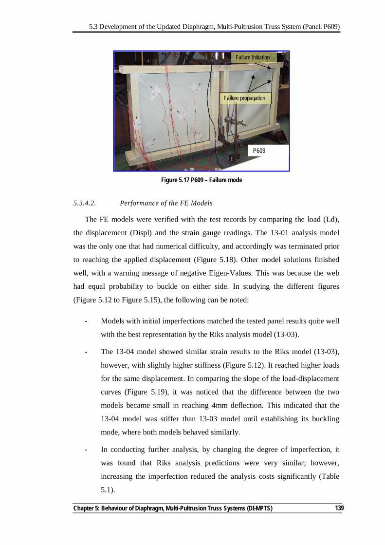
5.3 Development of the Updated Diaphragm, Multi-Pultrusion Truss System (Panel: P609)
Chapter 5: Behaviour of Diaphragm, Multi-Pultrusion Truss Systems (DI-MPTS)
139
5.3.4.2. Performance of the FE Models
The FE models were verified with the test records by comparing the load (Ld),
the displacement (Displ) and the strain gauge readings. The 13-01 analysis model
was the only one that had numerical difficulty, and accordingly was terminated prior
to reaching the applied displacement (Figure 5.18). Other model solutions finished
well, with a warning message of negative Eigen-Values. This was because the web
had equal probability to buckle on either side. In studying the different figures
(Figure 5.12 to Figure 5.15), the following can be noted:
- Models with initial imperfections matched the tested panel results quite well
with the best representation by the Riks analysis model (13-03).
- The 13-04 model showed similar strain results to the Riks model (13-03),
however, with slightly higher stiffness (Figure 5.12). It reached higher loads
for the same displacement. In comparing the slope of the load-displacement
curves (Figure 5.19), it was noticed that the difference between the two
models became small in reaching 4mm deflection. This indicated that the
13-04 model was stiffer than 13-03 model until establishing its buckling
mode, where both models behaved similarly.
- In conducting further analysis, by changing the degree of imperfection, it
was found that Riks analysis predictions were very similar; however,
increasing the imperfection reduced the analysis costs significantly (Table
5.1).
Figure 5.17 P609 – Failure mode
Failure Initiation
Failure propagation
P609
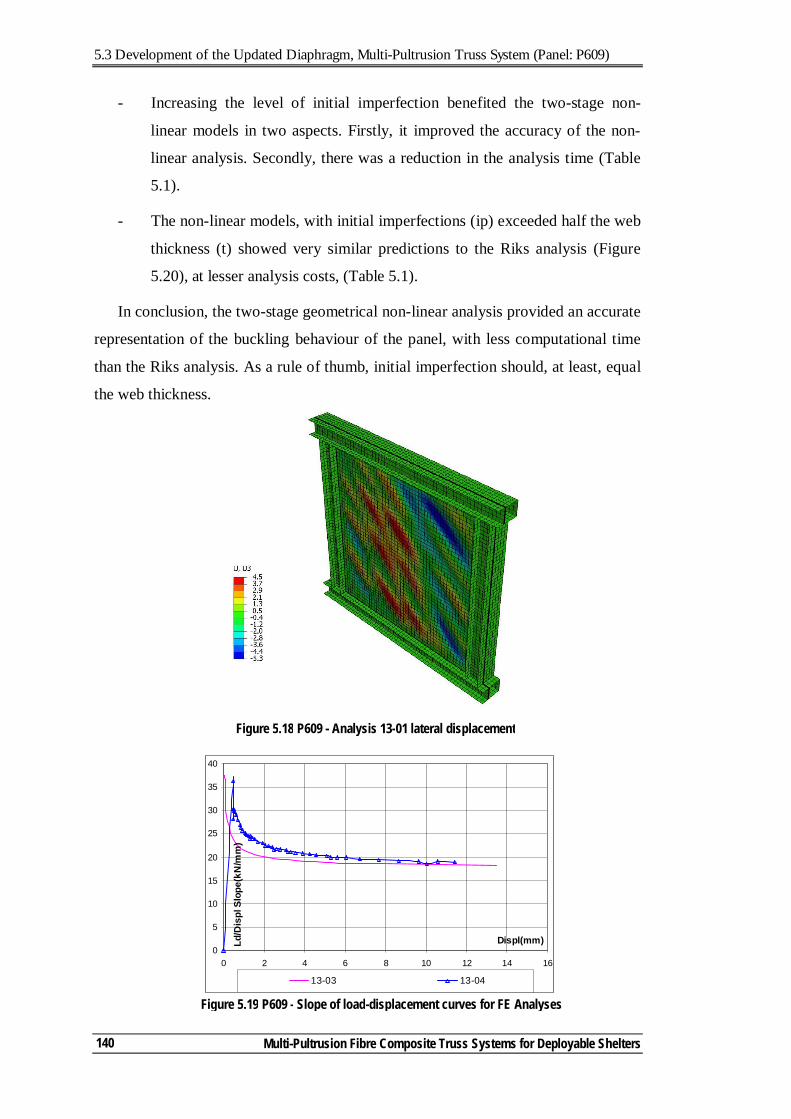
5.3 Development of the Updated Diaphragm, Multi-Pultrusion Truss System (Panel: P609)
Multi-Pultrusion Fibre Composite Truss Systems for Deployable Shelters
140
- Increasing the level of initial imperfection benefited the two-stage non-
linear models in two aspects. Firstly, it improved the accuracy of the non-
linear analysis. Secondly, there was a reduction in the analysis time (Table
5.1).
- The non-linear models, with initial imperfections (ip) exceeded half the web
thickness (t) showed very similar predictions to the Riks analysis (Figure
5.20), at lesser analysis costs, (Table 5.1).
In conclusion, the two-stage geometrical non-linear analysis provided an accurate
representation of the buckling behaviour of the panel, with less computational time
than the Riks analysis. As a rule of thumb, initial imperfection should, at least, equal
the web thickness.
Figure 5.19 P609 - Slope of load-displacement curves for FE Analyses
0
5
10
15
20
25
30
35
40
0 2 4 6 8 10 12 14 16
Displ(mm)Ld/D
ispl
Slo
pe(k
N/m
m)
13-03 13-04
Figure 5.18 P609 - Analysis 13-01 lateral displacement
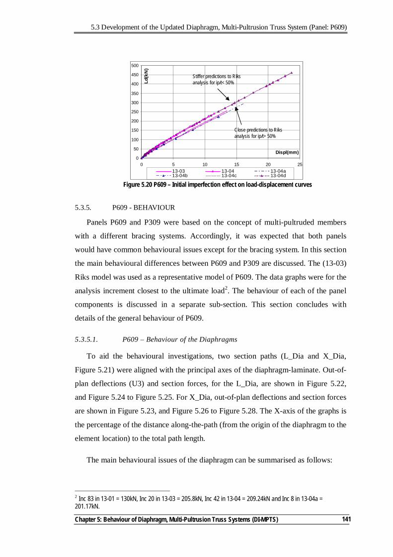
5.3 Development of the Updated Diaphragm, Multi-Pultrusion Truss System (Panel: P609)
Chapter 5: Behaviour of Diaphragm, Multi-Pultrusion Truss Systems (DI-MPTS)
141
5.3.5. P609 - BEHAVIOUR
Panels P609 and P309 were based on the concept of multi-pultruded members
with a different bracing systems. Accordingly, it was expected that both panels
would have common behavioural issues except for the bracing system. In this section
the main behavioural differences between P609 and P309 are discussed. The (13-03)
Riks model was used as a representative model of P609. The data graphs were for the
analysis increment closest to the ultimate load2. The behaviour of each of the panel
components is discussed in a separate sub-section. This section concludes with
details of the general behaviour of P609.
5.3.5.1. P609 – Behaviour of the Diaphragms
To aid the behavioural investigations, two section paths (L_Dia and X_Dia,
Figure 5.21) were aligned with the principal axes of the diaphragm-laminate. Out-of-
plan deflections (U3) and section forces, for the L_Dia, are shown in Figure 5.22,
and Figure 5.24 to Figure 5.25. For X_Dia, out-of-plan deflections and section forces
are shown in Figure 5.23, and Figure 5.26 to Figure 5.28. The X-axis of the graphs is
the percentage of the distance along-the-path (from the origin of the diaphragm to the
element location) to the total path length.
The main behavioural issues of the diaphragm can be summarised as follows:
2 Inc 83 in 13-01 = 130kN, Inc 20 in 13-03 = 205.8kN, Inc 42 in 13-04 = 209.24kN and Inc 8 in 13-04a = 201.17kN.
0
50
100
150
200
250
300
350
400
450
500
0 5 10 15 20 25
Displ(mm)Ld
(kN
)
13-03 13-04 13-04a13-04b 13-04c 13-04d
Figure 5.20 P609 – Initial imperfection effect on load-displacement curves
Close predictions to Riks analysis for ip/t> 50%
Stiffer predictions to Riks analysis for ip/t< 50%
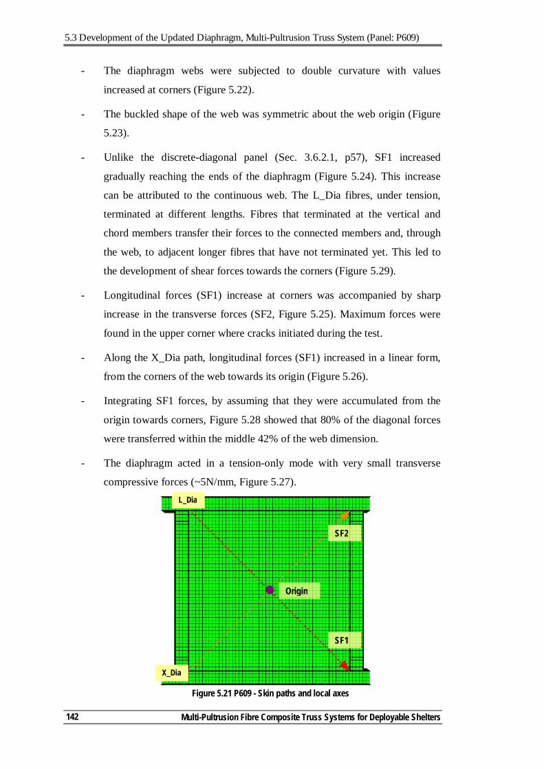
5.3 Development of the Updated Diaphragm, Multi-Pultrusion Truss System (Panel: P609)
Multi-Pultrusion Fibre Composite Truss Systems for Deployable Shelters
142
- The diaphragm webs were subjected to double curvature with values
increased at corners (Figure 5.22).
- The buckled shape of the web was symmetric about the web origin (Figure
5.23).
- Unlike the discrete-diagonal panel (Sec. 3.6.2.1, p57), SF1 increased
gradually reaching the ends of the diaphragm (Figure 5.24). This increase
can be attributed to the continuous web. The L_Dia fibres, under tension,
terminated at different lengths. Fibres that terminated at the vertical and
chord members transfer their forces to the connected members and, through
the web, to adjacent longer fibres that have not terminated yet. This led to
the development of shear forces towards the corners (Figure 5.29).
- Longitudinal forces (SF1) increase at corners was accompanied by sharp
increase in the transverse forces (SF2, Figure 5.25). Maximum forces were
found in the upper corner where cracks initiated during the test.
- Along the X_Dia path, longitudinal forces (SF1) increased in a linear form,
from the corners of the web towards its origin (Figure 5.26).
- Integrating SF1 forces, by assuming that they were accumulated from the
origin towards corners, Figure 5.28 showed that 80% of the diagonal forces
were transferred within the middle 42% of the web dimension.
- The diaphragm acted in a tension-only mode with very small transverse
compressive forces (~5N/mm, Figure 5.27).
Figure 5.21 P609 - Skin paths and local axes
SF2
SF1
Origin
X_Dia
L_Dia
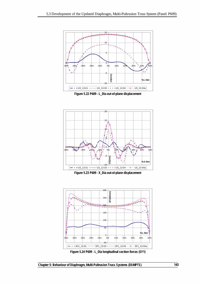
5.3 Development of the Updated Diaphragm, Multi-Pultrusion Truss System (Panel: P609)
Chapter 5: Behaviour of Diaphragm, Multi-Pultrusion Truss Systems (DI-MPTS)
143
-10
-5
0
5
10
15
-50% -40% -30% -20% -10% 0% 10% 20% 30% 40% 50%
% L Dim
U3(
mm
)
U3_13-01 U3_13-03 U3_13-04 U3_13-04a
Figure 5.22 P609 - L_Dia out-of-plane displacement
-50
0
50
100
150
200
250
300
-50% -40% -30% -20% -10% 0% 10% 20% 30% 40% 50%
% L Dim
SF1(
N/m
m)
SF1_13-01 SF1_13-03 SF1_13-04 SF1_13-04a
Figure 5.24 P609 - L_Dia longitudinal section forces (SF1)
Figure 5.23 P609 - X_Dia out-of-plane displacement
-10
-5
0
5
10
15
20
-50% -40% -30% -20% -10% 0% 10% 20% 30% 40% 50%
% X Dim
U3(
mm
)
U3_13-01 U3_13-03 U3_13-04 U3_13-04a
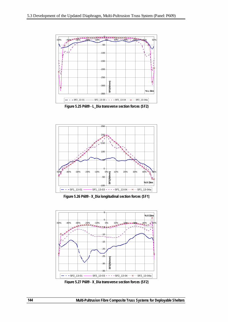
5.3 Development of the Updated Diaphragm, Multi-Pultrusion Truss System (Panel: P609)
Multi-Pultrusion Fibre Composite Truss Systems for Deployable Shelters
144
-350
-300
-250
-200
-150
-100
-50
0-50% -40% -30% -20% -10% 0% 10% 20% 30% 40% 50%
% L DimSF2(
N/m
m)
SF2_13-01 SF2_13-03 SF2_13-04 SF2_13-04a
Figure 5.25 P609 - L_Dia transverse section forces (SF2)
-100
-50
0
50
100
150
200
250
-50% -40% -30% -20% -10% 0% 10% 20% 30% 40% 50%
% X DimSF1(
N/m
m)
SF1_13-01 SF1_13-03 SF1_13-04 SF1_13-04a
Figure 5.26 P609 - X_Dia longitudinal section forces (SF1)
Figure 5.27 P609 - X_Dia transverse section forces (SF2)
-35
-30
-25
-20
-15
-10
-5
0
5
-50% -40% -30% -20% -10% 0% 10% 20% 30% 40% 50%
% X Dim
SF2(
N/m
m)
SF2_13-01 SF2_13-03 SF2_13-04 SF2_13-04a
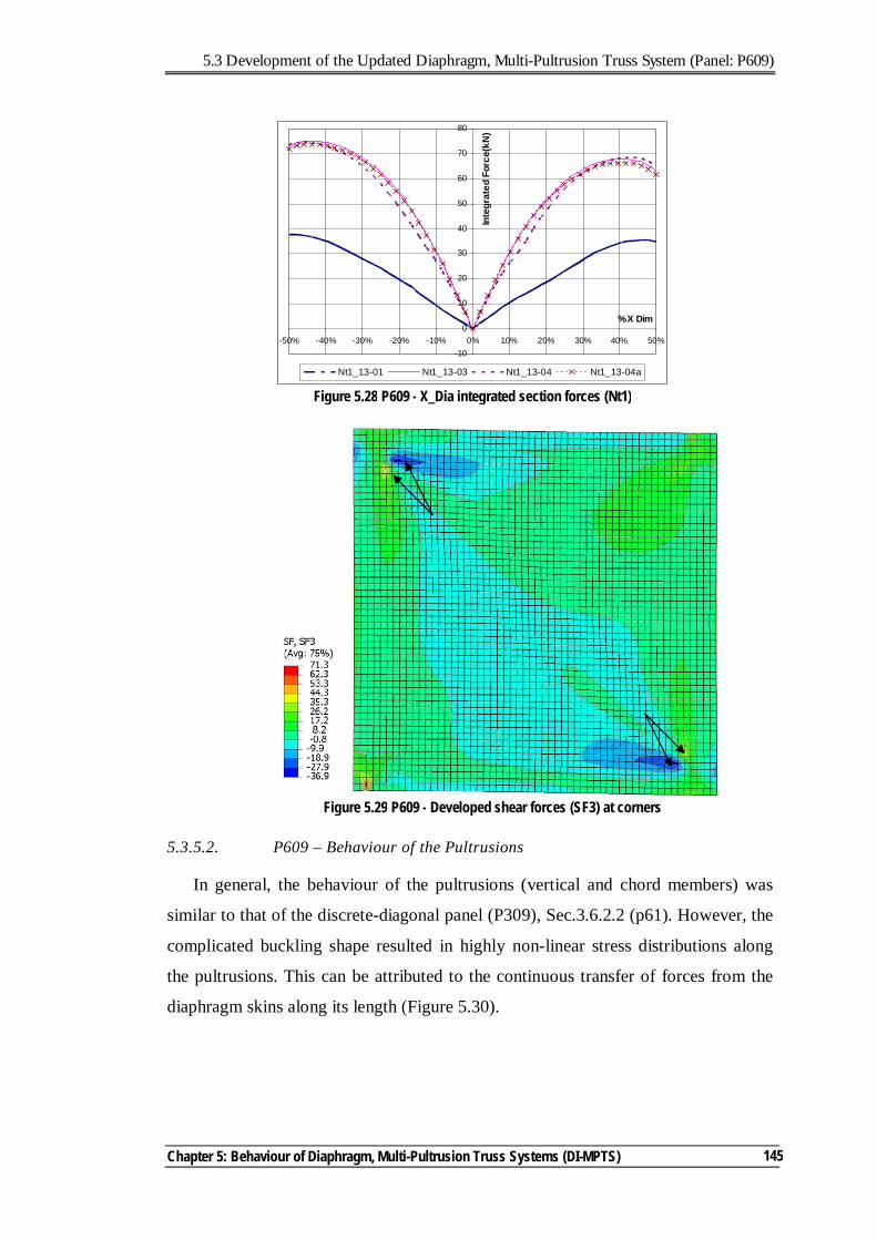
5.3 Development of the Updated Diaphragm, Multi-Pultrusion Truss System (Panel: P609)
Chapter 5: Behaviour of Diaphragm, Multi-Pultrusion Truss Systems (DI-MPTS)
145
5.3.5.2. P609 – Behaviour of the Pultrusions
In general, the behaviour of the pultrusions (vertical and chord members) was
similar to that of the discrete-diagonal panel (P309), Sec.3.6.2.2 (p61). However, the
complicated buckling shape resulted in highly non-linear stress distributions along
the pultrusions. This can be attributed to the continuous transfer of forces from the
diaphragm skins along its length (Figure 5.30).
Figure 5.28 P609 - X_Dia integrated section forces (Nt1)
-10
0
10
20
30
40
50
60
70
80
-50% -40% -30% -20% -10% 0% 10% 20% 30% 40% 50%
% X Dim
Inte
grat
ed F
orce
(kN
)
Nt1_13-01 Nt1_13-03 Nt1_13-04 Nt1_13-04a
Figure 5.29 P609 - Developed shear forces (SF3) at corners
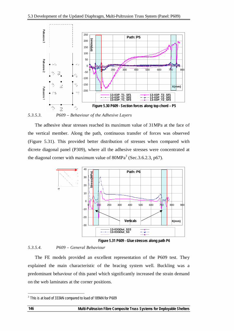
5.3 Development of the Updated Diaphragm, Multi-Pultrusion Truss System (Panel: P609)
Multi-Pultrusion Fibre Composite Truss Systems for Deployable Shelters
146
5.3.5.3. P609 – Behaviour of the Adhesive Layers
The adhesive shear stresses reached its maximum value of 31MPa at the face of
the vertical member. Along the path, continuous transfer of forces was observed
(Figure 5.31). This provided better distribution of stresses when compared with
dicrete diagonal panel (P309), where all the adhesive stresses were concentrated at
the diagonal corner with maximum value of 80MPa3 (Sec.3.6.2.3, p67).
5.3.5.4. P609 – General Behaviour
The FE models provided an excellent representation of the P609 test. They
explained the main characteristic of the bracing system well. Buckling was a
predominant behaviour of this panel which significantly increased the strain demand
on the web laminates at the corner positions.
3 This is at load of 333kN compared to load of 189kN for P609
Path: P5
-200
-150
-100
-50
0
50
100
150
200
250
0 100 200 300 400 500 600 700 800
X(mm)SF
(N/m
m)
13-03P_T1_SF1 13-03P_T2_SF113-03P_T1_SF2 13-03P_T2_SF213-03P_T1_SF3 13-03P_T2_SF3
Figure 5.30 P609 - Section forces along top chord – P5
Path: P6
-30
-20
-10
0
10
20
30
40
0 100 200 300 400 500 600 700 800 900
X(mm)
Stre
ss(M
Pa)
13-03GOut_S3313-03GOut_S3
Figure 5.31 P609 - Glue stresses along path P6
Verticals
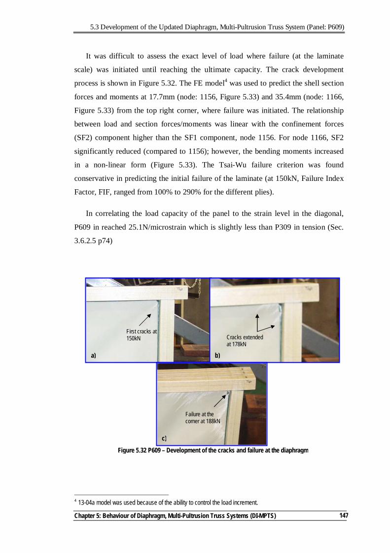
5.3 Development of the Updated Diaphragm, Multi-Pultrusion Truss System (Panel: P609)
Chapter 5: Behaviour of Diaphragm, Multi-Pultrusion Truss Systems (DI-MPTS)
147
It was difficult to assess the exact level of load where failure (at the laminate
scale) was initiated until reaching the ultimate capacity. The crack development
process is shown in Figure 5.32. The FE model4 was used to predict the shell section
forces and moments at 17.7mm (node: 1156, Figure 5.33) and 35.4mm (node: 1166,
Figure 5.33) from the top right corner, where failure was initiated. The relationship
between load and section forces/moments was linear with the confinement forces
(SF2) component higher than the SF1 component, node 1156. For node 1166, SF2
significantly reduced (compared to 1156); however, the bending moments increased
in a non-linear form (Figure 5.33). The Tsai-Wu failure criterion was found
conservative in predicting the initial failure of the laminate (at 150kN, Failure Index
Factor, FIF, ranged from 100% to 290% for the different plies).
In correlating the load capacity of the panel to the strain level in the diagonal,
P609 in reached 25.1N/microstrain which is slightly less than P309 in tension (Sec.
3.6.2.5 p74)
4 13-04a model was used because of the ability to control the load increment.
First cracks at 150kN Cracks extended
at 178kN
Figure 5.32 P609 – Development of the cracks and failure at the diaphragm
Failure at the corner at 188kN
a) b)
c)
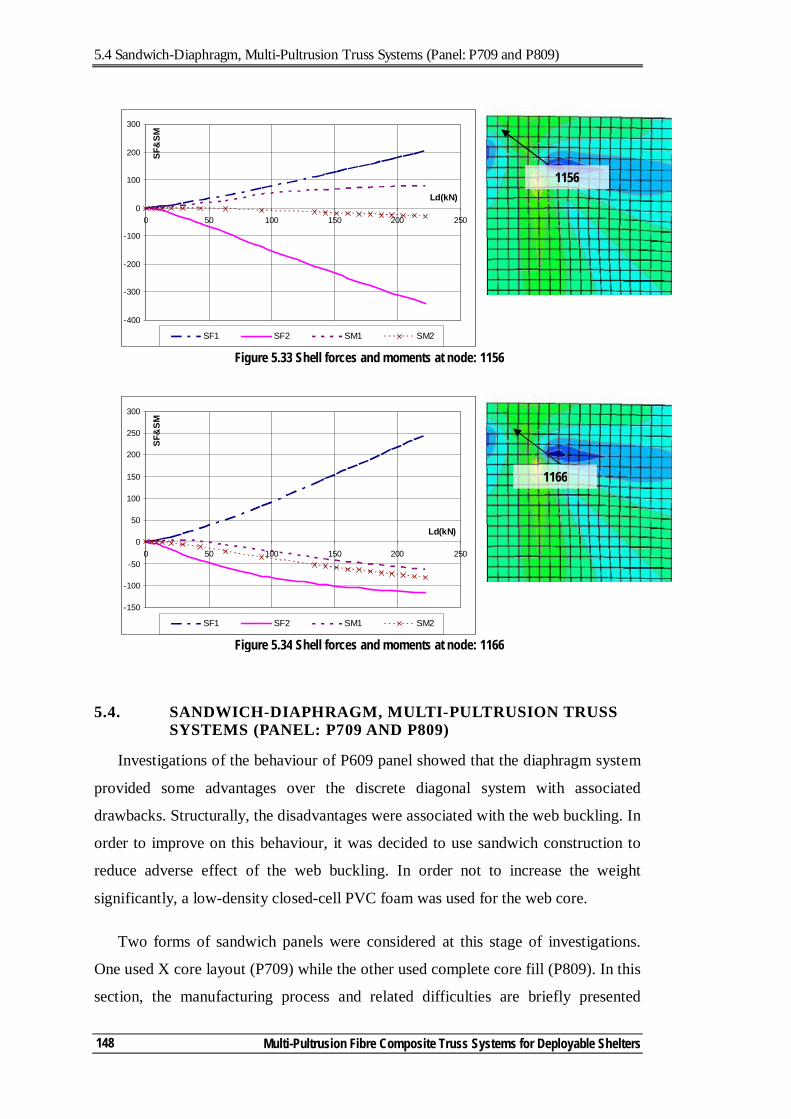
5.4 Sandwich-Diaphragm, Multi-Pultrusion Truss Systems (Panel: P709 and P809)
Multi-Pultrusion Fibre Composite Truss Systems for Deployable Shelters
148
5.4. SANDWICH-DIAPHRAGM, MULTI-PULTRUSION TRUSS SYSTEMS (PANEL: P709 AND P809)
Investigations of the behaviour of P609 panel showed that the diaphragm system
provided some advantages over the discrete diagonal system with associated
drawbacks. Structurally, the disadvantages were associated with the web buckling. In
order to improve on this behaviour, it was decided to use sandwich construction to
reduce adverse effect of the web buckling. In order not to increase the weight
significantly, a low-density closed-cell PVC foam was used for the web core.
Two forms of sandwich panels were considered at this stage of investigations.
One used X core layout (P709) while the other used complete core fill (P809). In this
section, the manufacturing process and related difficulties are briefly presented
Figure 5.33 Shell forces and moments at node: 1156
-400
-300
-200
-100
0
100
200
300
0 50 100 150 200 250
Ld(kN)
SF&
SM
SF1 SF2 SM1 SM2
1156
-150
-100
-50
0
50
100
150
200
250
300
0 50 100 150 200 250
Ld(kN)
SF&
SM
SF1 SF2 SM1 SM2
Figure 5.34 Shell forces and moments at node: 1166
1166
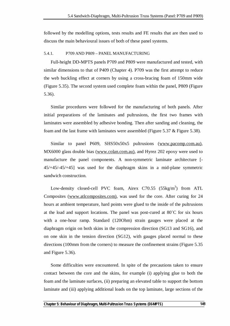
5.4 Sandwich-Diaphragm, Multi-Pultrusion Truss Systems (Panel: P709 and P809)
Chapter 5: Behaviour of Diaphragm, Multi-Pultrusion Truss Systems (DI-MPTS)
149
followed by the modelling options, tests results and FE results that are then used to
discuss the main behavioural issues of both of these panel systems.
5.4.1. P709 AND P809 – PANEL MANUFACTURING
Full-height DD-MPTS panels P709 and P809 were manufactured and tested, with
similar dimensions to that of P409 (Chapter 4). P709 was the first attempt to reduce
the web buckling effect at corners by using a cross-bracing foam of 150mm wide
(Figure 5.35). The second system used complete foam within the panel, P809 (Figure
5.36).
Similar procedures were followed for the manufacturing of both panels. After
initial preparations of the laminates and pultrusions, the first two frames with
laminates were assembled by adhesive bonding. Then after sanding and cleaning, the
foam and the last frame with laminates were assembled (Figure 5.37 & Figure 5.38).
Similar to panel P609, SHS50x50x5 pultrusions (www.pacomp.com.au),
MX6000 glass double bias (www.colan.com.au), and Hyrez 202 epoxy were used to
manufacture the panel components. A non-symmetric laminate architecture [-
45/+45/-45/+45] was used for the diaphragm skins in a mid-plane symmetric
sandwich construction.
Low-density closed-cell PVC foam, Airex C70.55 (55kg/m3) from ATL
Composites (www.atlcomposites.com), was used for the core. After curing for 24
hours at ambient temperature, hard points were glued to the inside of the pultrusions
at the load and support locations. The panel was post-cured at 80˚C for six hours
with a one-hour ramp. Standard (120Ohm) strain gauges were placed at the
diaphragm origin on both skins in the compression direction (SG13 and SG16), and
on one skin in the tension direction (SG12), with gauges placed normal to these
directions (100mm from the corners) to measure the confinement strains (Figure 5.35
and Figure 5.36).
Some difficulties were encountered. In spite of the precautions taken to ensure
contact between the core and the skins, for example (i) applying glue to both the
foam and the laminate surfaces, (ii) preparing an elevated table to support the bottom
laminate and (iii) applying additional loads on the top laminate, large sections of the
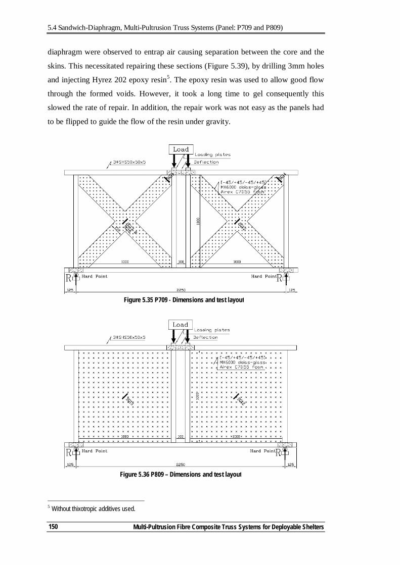
5.4 Sandwich-Diaphragm, Multi-Pultrusion Truss Systems (Panel: P709 and P809)
Multi-Pultrusion Fibre Composite Truss Systems for Deployable Shelters
150
diaphragm were observed to entrap air causing separation between the core and the
skins. This necessitated repairing these sections (Figure 5.39), by drilling 3mm holes
and injecting Hyrez 202 epoxy resin5. The epoxy resin was used to allow good flow
through the formed voids. However, it took a long time to gel consequently this
slowed the rate of repair. In addition, the repair work was not easy as the panels had
to be flipped to guide the flow of the resin under gravity.
5 Without thixotropic additives used.
Figure 5.35 P709 - Dimensions and test layout
Figure 5.36 P809 – Dimensions and test layout
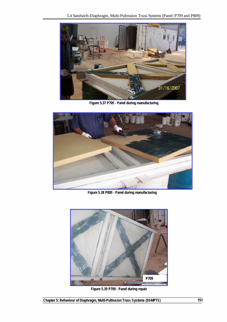
5.4 Sandwich-Diaphragm, Multi-Pultrusion Truss Systems (Panel: P709 and P809)
Chapter 5: Behaviour of Diaphragm, Multi-Pultrusion Truss Systems (DI-MPTS)
151
Figure 5.39 P709 - Panel during repair
P709
Figure 5.38 P809 - Panel during manufacturing
Figure 5.37 P709 - Panel during manufacturing
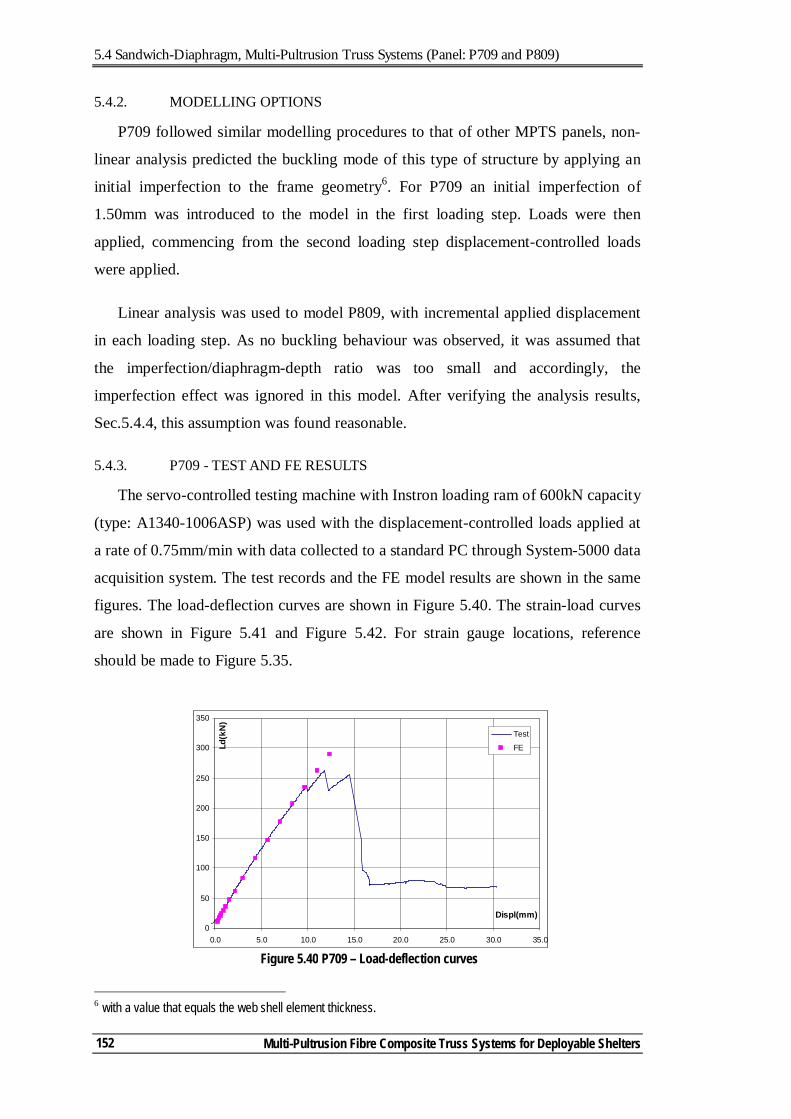
5.4 Sandwich-Diaphragm, Multi-Pultrusion Truss Systems (Panel: P709 and P809)
Multi-Pultrusion Fibre Composite Truss Systems for Deployable Shelters
152
5.4.2. MODELLING OPTIONS
P709 followed similar modelling procedures to that of other MPTS panels, non-
linear analysis predicted the buckling mode of this type of structure by applying an
initial imperfection to the frame geometry6. For P709 an initial imperfection of
1.50mm was introduced to the model in the first loading step. Loads were then
applied, commencing from the second loading step displacement-controlled loads
were applied.
Linear analysis was used to model P809, with incremental applied displacement
in each loading step. As no buckling behaviour was observed, it was assumed that
the imperfection/diaphragm-depth ratio was too small and accordingly, the
imperfection effect was ignored in this model. After verifying the analysis results,
Sec.5.4.4, this assumption was found reasonable.
5.4.3. P709 - TEST AND FE RESULTS
The servo-controlled testing machine with Instron loading ram of 600kN capacity
(type: A1340-1006ASP) was used with the displacement-controlled loads applied at
a rate of 0.75mm/min with data collected to a standard PC through System-5000 data
acquisition system. The test records and the FE model results are shown in the same
figures. The load-deflection curves are shown in Figure 5.40. The strain-load curves
are shown in Figure 5.41 and Figure 5.42. For strain gauge locations, reference
should be made to Figure 5.35.
6 with a value that equals the web shell element thickness.
0
50
100
150
200
250
300
350
0.0 5.0 10.0 15.0 20.0 25.0 30.0 35.0
Displ(mm)
Ld(k
N)
Test
FE
Figure 5.40 P709 – Load-deflection curves
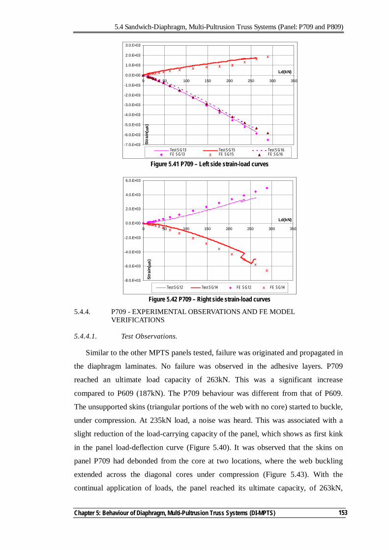
5.4 Sandwich-Diaphragm, Multi-Pultrusion Truss Systems (Panel: P709 and P809)
Chapter 5: Behaviour of Diaphragm, Multi-Pultrusion Truss Systems (DI-MPTS)
153
5.4.4. P709 - EXPERIMENTAL OBSERVATIONS AND FE MODEL VERIFICATIONS
5.4.4.1. Test Observations.
Similar to the other MPTS panels tested, failure was originated and propagated in
the diaphragm laminates. No failure was observed in the adhesive layers. P709
reached an ultimate load capacity of 263kN. This was a significant increase
compared to P609 (187kN). The P709 behaviour was different from that of P609.
The unsupported skins (triangular portions of the web with no core) started to buckle,
under compression. At 235kN load, a noise was heard. This was associated with a
slight reduction of the load-carrying capacity of the panel, which shows as first kink
in the panel load-deflection curve (Figure 5.40). It was observed that the skins on
panel P709 had debonded from the core at two locations, where the web buckling
extended across the diagonal cores under compression (Figure 5.43). With the
continual application of loads, the panel reached its ultimate capacity, of 263kN,
Figure 5.41 P709 – Left side strain-load curves
-7.0.E+03
-6.0.E+03
-5.0.E+03
-4.0.E+03
-3.0.E+03
-2.0.E+03
-1.0.E+03
0.0.E+00
1.0.E+03
2.0.E+03
3.0.E+03
0 50 100 150 200 250 300 350
Ld(kN)
Stra
in( µ
s)Test SG13 Test SG15 Test SG16FE SG13 FE SG15 FE SG16
Figure 5.42 P709 – Right side strain-load curves
-8.0.E+03
-6.0.E+03
-4.0.E+03
-2.0.E+03
0.0.E+00
2.0.E+03
4.0.E+03
6.0.E+03
0 50 100 150 200 250 300 350
Ld(kN)
Stra
in( µ
s)
Test SG12 Test SG14 FE SG12 FE SG14
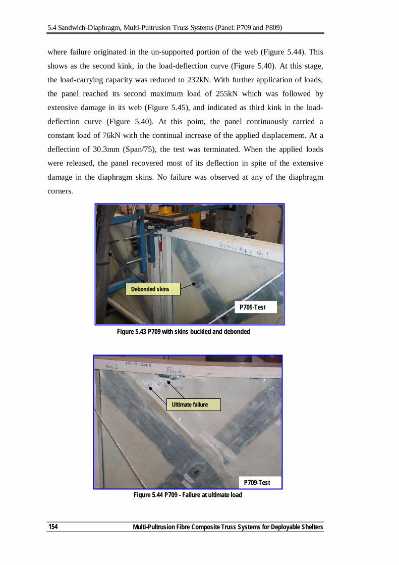
5.4 Sandwich-Diaphragm, Multi-Pultrusion Truss Systems (Panel: P709 and P809)
Multi-Pultrusion Fibre Composite Truss Systems for Deployable Shelters
154
where failure originated in the un-supported portion of the web (Figure 5.44). This
shows as the second kink, in the load-deflection curve (Figure 5.40). At this stage,
the load-carrying capacity was reduced to 232kN. With further application of loads,
the panel reached its second maximum load of 255kN which was followed by
extensive damage in its web (Figure 5.45), and indicated as third kink in the load-
deflection curve (Figure 5.40). At this point, the panel continuously carried a
constant load of 76kN with the continual increase of the applied displacement. At a
deflection of 30.3mm (Span/75), the test was terminated. When the applied loads
were released, the panel recovered most of its deflection in spite of the extensive
damage in the diaphragm skins. No failure was observed at any of the diaphragm
corners.
Figure 5.43 P709 with skins buckled and debonded
Debonded skins
P709-Test
Figure 5.44 P709 - Failure at ultimate load
Ultimate failure
P709-Test
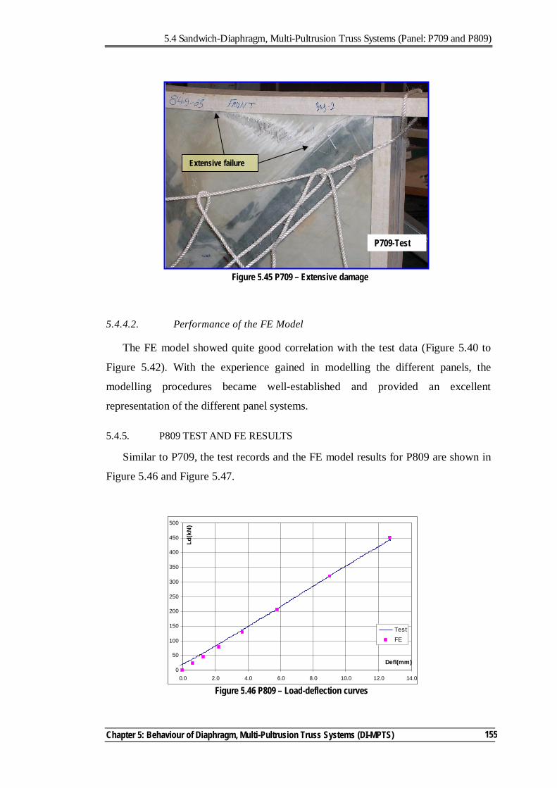
5.4 Sandwich-Diaphragm, Multi-Pultrusion Truss Systems (Panel: P709 and P809)
Chapter 5: Behaviour of Diaphragm, Multi-Pultrusion Truss Systems (DI-MPTS)
155
5.4.4.2. Performance of the FE Model
The FE model showed quite good correlation with the test data (Figure 5.40 to
Figure 5.42). With the experience gained in modelling the different panels, the
modelling procedures became well-established and provided an excellent
representation of the different panel systems.
5.4.5. P809 TEST AND FE RESULTS
Similar to P709, the test records and the FE model results for P809 are shown in
Figure 5.46 and Figure 5.47.
Figure 5.46 P809 – Load-deflection curves
0
50
100
150
200
250
300
350
400
450
500
0.0 2.0 4.0 6.0 8.0 10.0 12.0 14.0
Defl(mm)
Ld(k
N)
Test
FE
Figure 5.45 P709 – Extensive damage
Extensive failure
P709-Test
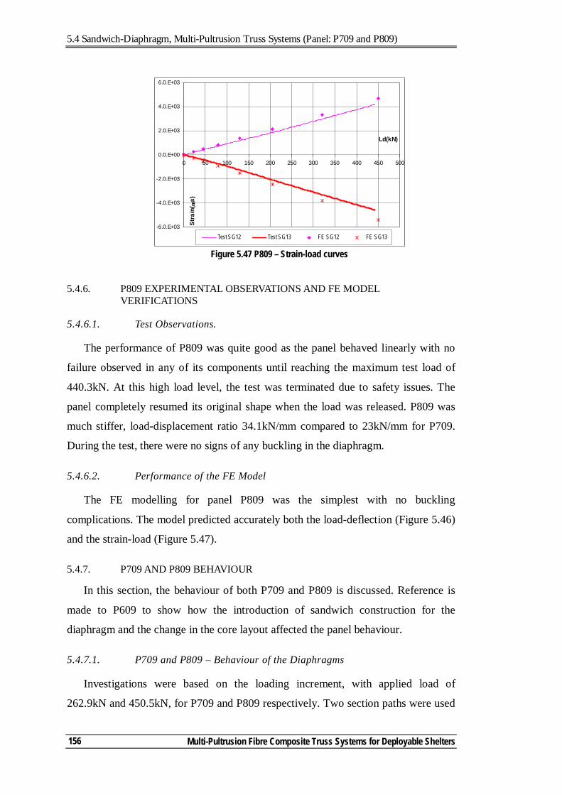
5.4 Sandwich-Diaphragm, Multi-Pultrusion Truss Systems (Panel: P709 and P809)
Multi-Pultrusion Fibre Composite Truss Systems for Deployable Shelters
156
5.4.6. P809 EXPERIMENTAL OBSERVATIONS AND FE MODEL VERIFICATIONS
5.4.6.1. Test Observations.
The performance of P809 was quite good as the panel behaved linearly with no
failure observed in any of its components until reaching the maximum test load of
440.3kN. At this high load level, the test was terminated due to safety issues. The
panel completely resumed its original shape when the load was released. P809 was
much stiffer, load-displacement ratio 34.1kN/mm compared to 23kN/mm for P709.
During the test, there were no signs of any buckling in the diaphragm.
5.4.6.2. Performance of the FE Model
The FE modelling for panel P809 was the simplest with no buckling
complications. The model predicted accurately both the load-deflection (Figure 5.46)
and the strain-load (Figure 5.47).
5.4.7. P709 AND P809 BEHAVIOUR
In this section, the behaviour of both P709 and P809 is discussed. Reference is
made to P609 to show how the introduction of sandwich construction for the
diaphragm and the change in the core layout affected the panel behaviour.
5.4.7.1. P709 and P809 – Behaviour of the Diaphragms
Investigations were based on the loading increment, with applied load of
262.9kN and 450.5kN, for P709 and P809 respectively. Two section paths were used
Figure 5.47 P809 – Strain-load curves
-6.0.E+03
-4.0.E+03
-2.0.E+03
0.0.E+00
2.0.E+03
4.0.E+03
6.0.E+03
0 50 100 150 200 250 300 350 400 450 500
Ld(kN)
Stra
in( µ
s)
Test SG12 Test SG13 FE SG12 FE SG13
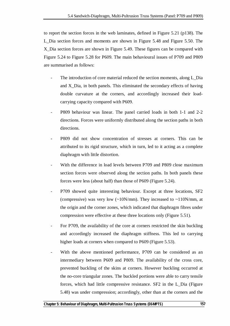
5.4 Sandwich-Diaphragm, Multi-Pultrusion Truss Systems (Panel: P709 and P809)
Chapter 5: Behaviour of Diaphragm, Multi-Pultrusion Truss Systems (DI-MPTS)
157
to report the section forces in the web laminates, defined in Figure 5.21 (p138). The
L_Dia section forces and moments are shown in Figure 5.48 and Figure 5.50. The
X_Dia section forces are shown in Figure 5.49. These figures can be compared with
Figure 5.24 to Figure 5.28 for P609. The main behavioural issues of P709 and P809
are summarised as follows:
- The introduction of core material reduced the section moments, along L_Dia
and X_Dia, in both panels. This eliminated the secondary effects of having
double curvature at the corners, and accordingly increased their load-
carrying capacity compared with P609.
- P809 behaviour was linear. The panel carried loads in both 1-1 and 2-2
directions. Forces were uniformly distributed along the section paths in both
directions.
- P809 did not show concentration of stresses at corners. This can be
attributed to its rigid structure, which in turn, led to it acting as a complete
diaphragm with little distortion.
- With the difference in load levels between P709 and P809 close maximum
section forces were observed along the section paths. In both panels these
forces were less (about half) than those of P609 (Figure 5.24).
- P709 showed quite interesting behaviour. Except at three locations, SF2
(compressive) was very low (~10N/mm). They increased to ~110N/mm, at
the origin and the corner zones, which indicated that diaphragm fibres under
compression were effective at these three locations only (Figure 5.51).
- For P709, the availability of the core at corners restricted the skin buckling
and accordingly increased the diaphragm stiffness. This led to carrying
higher loads at corners when compared to P609 (Figure 5.53).
- With the above mentioned performance, P709 can be considered as an
intermediary between P609 and P809. The availability of the cross core,
prevented buckling of the skins at corners. However buckling occurred at
the no-core triangular zones. The buckled portions were able to carry tensile
forces, which had little compressive resistance. SF2 in the L_Dia (Figure
5.48) was under compression; accordingly, other than at the corners and the
5.4 Sandwich-Diaphragm, Multi-Pultrusion Truss Systems (Panel: P709 and P809)
Multi-Pultrusion Fibre Composite Truss Systems for Deployable Shelters
158
central zones (where core material was available), there was very little force
transfer. In the X_Dia (Figure 5.49), similar to P609 (Figure 5.26), tensile
forces were developing from the corners towards the web origin. This
means that most of the tensile forces were bundled within the central zone.
- In calculating the resisting diaphragm forces, from Figure 5.53, the P709
force components were 141.8kN under compression and 131.4kN under
tension. This totals 273.2kN.
- For P809, the force components were 247.2kN under compression and
220.5kN under tension. This totals 467.7kN.
- For P609, The force components were (52.9kN) under compression and
(136.2kN) under tension. This totals 189.1kN.
- For P709 and P809, the diaphragms forces were shared between
compressive and tensile forces (Figure 5.51 & Figure 5.52) while almost all
forces were carried by the diaphragm under tension in P609.
- P809 showed equal force distributions across the diaphragm while P709 had
localised tensile forces around the diaphragm origin and compression forces
at the origin and the corners.
- For P709, ultimate strains in the diaphragm were 0.55% under compression
(SG13 and SG16) and 0.36% under tension (SG12), Figure 5.54. Reaching
the ultimate failure, compressive strains dropped to 0.28% (due to failure in
their fibre directions and accordingly releasing the compressive force
components), while the tensile strains were proportional to the applied
loads.
- This indicated that P709 still had significant reserve. Failure would continue
to propagate across the fibres under compression (due to the extended
buckling effect) but the fibres (in the core zone) under tension will keep
carrying the loads until reaching their failure strains.
- As failure occurred in compression fibres due to the extension of the
buckling of the un-supported zones, the panel capacity and post-failure
behaviour can be improved by preventing this extension. This can be
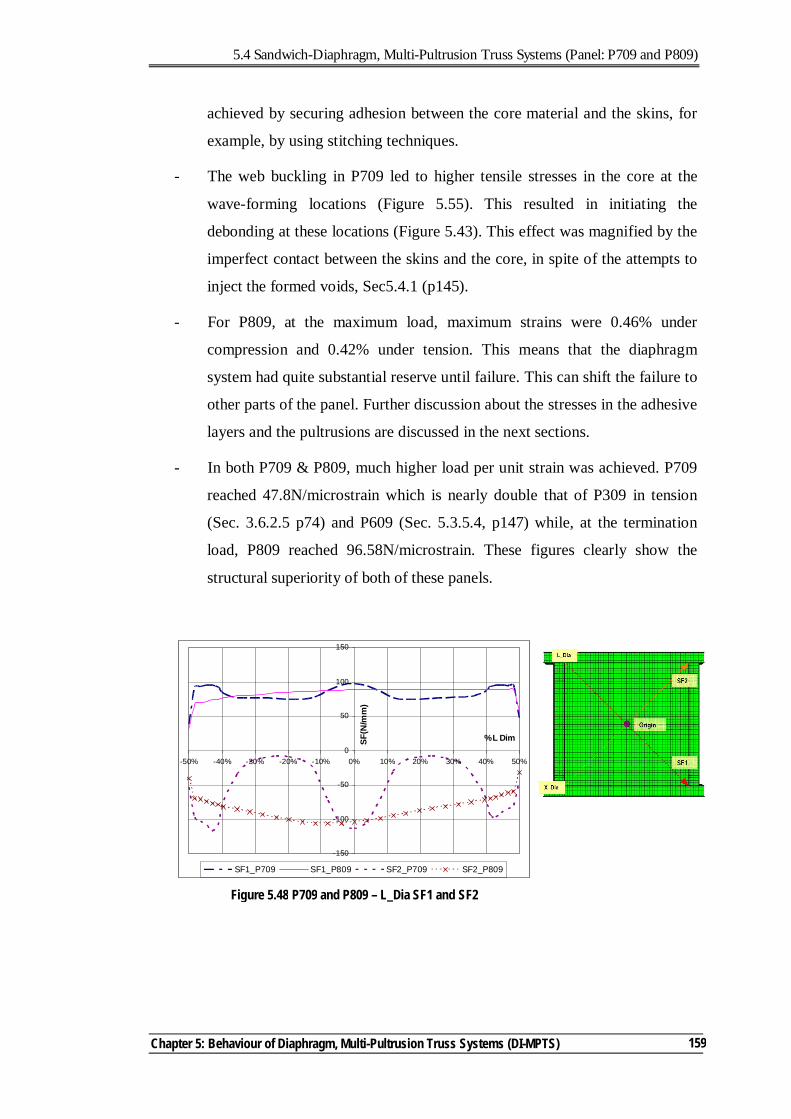
5.4 Sandwich-Diaphragm, Multi-Pultrusion Truss Systems (Panel: P709 and P809)
Chapter 5: Behaviour of Diaphragm, Multi-Pultrusion Truss Systems (DI-MPTS)
159
achieved by securing adhesion between the core material and the skins, for
example, by using stitching techniques.
- The web buckling in P709 led to higher tensile stresses in the core at the
wave-forming locations (Figure 5.55). This resulted in initiating the
debonding at these locations (Figure 5.43). This effect was magnified by the
imperfect contact between the skins and the core, in spite of the attempts to
inject the formed voids, Sec5.4.1 (p145).
- For P809, at the maximum load, maximum strains were 0.46% under
compression and 0.42% under tension. This means that the diaphragm
system had quite substantial reserve until failure. This can shift the failure to
other parts of the panel. Further discussion about the stresses in the adhesive
layers and the pultrusions are discussed in the next sections.
- In both P709 & P809, much higher load per unit strain was achieved. P709
reached 47.8N/microstrain which is nearly double that of P309 in tension
(Sec. 3.6.2.5 p74) and P609 (Sec. 5.3.5.4, p147) while, at the termination
load, P809 reached 96.58N/microstrain. These figures clearly show the
structural superiority of both of these panels.
Figure 5.48 P709 and P809 – L_Dia SF1 and SF2
-150
-100
-50
0
50
100
150
-50% -40% -30% -20% -10% 0% 10% 20% 30% 40% 50%
% L DimSF(N
/mm
)
SF1_P709 SF1_P809 SF2_P709 SF2_P809
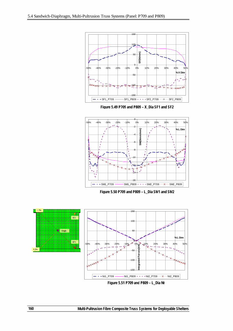
5.4 Sandwich-Diaphragm, Multi-Pultrusion Truss Systems (Panel: P709 and P809)
Multi-Pultrusion Fibre Composite Truss Systems for Deployable Shelters
160
Figure 5.50 P709 and P809 – L_Dia SM1 and SM2
-16
-14
-12
-10
-8
-6
-4
-2
0-50% -40% -30% -20% -10% 0% 10% 20% 30% 40% 50%
% L Dim
SM(N
mm
/mm
)
SM1_P709 SM1_P809 SM2_P709 SM2_P809
Figure 5.49 P709 and P809 – X_Dia SF1 and SF2
-150
-100
-50
0
50
100
150
-50% -40% -30% -20% -10% 0% 10% 20% 30% 40% 50%
% X Dim
SF(N
/mm
)
SF1_P709 SF1_P809 SF2_P709 SF2_P809
-150
-100
-50
0
50
100
150
-50% -40% -30% -20% -10% 0% 10% 20% 30% 40% 50%
% L Dim
Inte
grat
ed F
orce
s(kN
)
Nt1_P709 Nt1_P809 Nt2_P709 Nt2_P809
`
Figure 5.51 P709 and P809 – L_Dia Nt
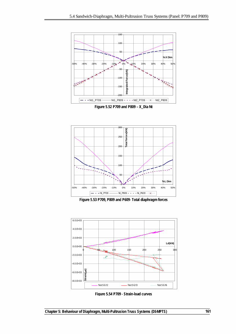
5.4 Sandwich-Diaphragm, Multi-Pultrusion Truss Systems (Panel: P709 and P809)
Chapter 5: Behaviour of Diaphragm, Multi-Pultrusion Truss Systems (DI-MPTS)
161
-200
-150
-100
-50
0
50
100
150
-50% -40% -30% -20% -10% 0% 10% 20% 30% 40% 50%
% X Dim
Inte
grat
ed F
orce
(kN
)
Nt1_P709 Nt1_P809 Nt2_P709 Nt2_P809
Figure 5.52 P709 and P809 – X_Dia Nt
0
50
100
150
200
250
300
-50% -40% -30% -20% -10% 0% 10% 20% 30% 40% 50%
% L Dim
Tota
l for
ces(
kN)
Nt_P709 Nt_P809 Nt_P609
Figure 5.53 P709, P809 and P609- Total diaphragm forces
-8.0.E+03
-6.0.E+03
-4.0.E+03
-2.0.E+03
0.0.E+00
2.0.E+03
4.0.E+03
6.0.E+03
0 50 100 150 200 250 300
Ld(kN)
Stra
in( µ
s)
Test SG12 Test SG13 Test SG16
Figure 5.54 P709 - Strain-load curves
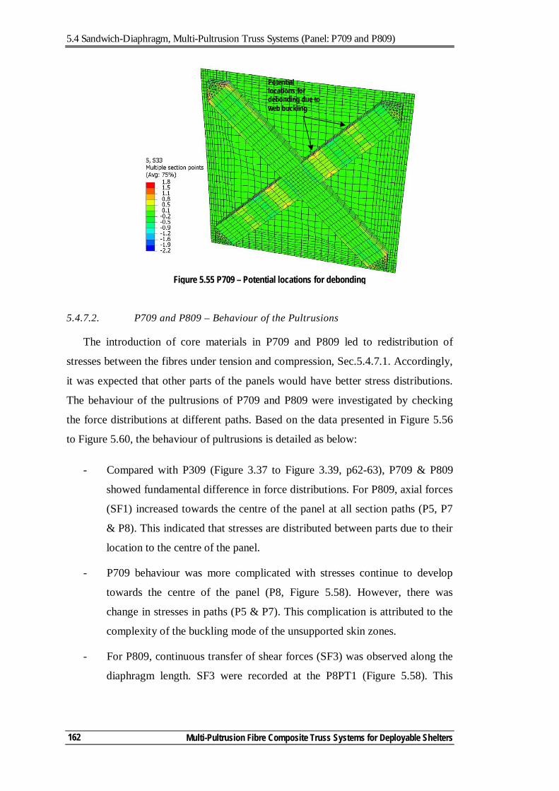
5.4 Sandwich-Diaphragm, Multi-Pultrusion Truss Systems (Panel: P709 and P809)
Multi-Pultrusion Fibre Composite Truss Systems for Deployable Shelters
162
5.4.7.2. P709 and P809 – Behaviour of the Pultrusions
The introduction of core materials in P709 and P809 led to redistribution of
stresses between the fibres under tension and compression, Sec.5.4.7.1. Accordingly,
it was expected that other parts of the panels would have better stress distributions.
The behaviour of the pultrusions of P709 and P809 were investigated by checking
the force distributions at different paths. Based on the data presented in Figure 5.56
to Figure 5.60, the behaviour of pultrusions is detailed as below:
- Compared with P309 (Figure 3.37 to Figure 3.39, p62-63), P709 & P809
showed fundamental difference in force distributions. For P809, axial forces
(SF1) increased towards the centre of the panel at all section paths (P5, P7
& P8). This indicated that stresses are distributed between parts due to their
location to the centre of the panel.
- P709 behaviour was more complicated with stresses continue to develop
towards the centre of the panel (P8, Figure 5.58). However, there was
change in stresses in paths (P5 & P7). This complication is attributed to the
complexity of the buckling mode of the unsupported skin zones.
- For P809, continuous transfer of shear forces (SF3) was observed along the
diaphragm length. SF3 were recorded at the P8PT1 (Figure 5.58). This
Potential locations for debonding due to web buckling
Figure 5.55 P709 – Potential locations for debonding
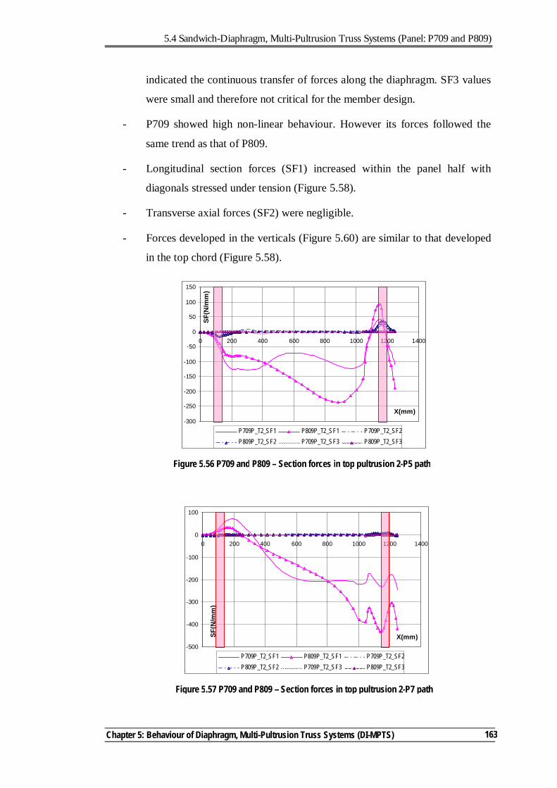
5.4 Sandwich-Diaphragm, Multi-Pultrusion Truss Systems (Panel: P709 and P809)
Chapter 5: Behaviour of Diaphragm, Multi-Pultrusion Truss Systems (DI-MPTS)
163
indicated the continuous transfer of forces along the diaphragm. SF3 values
were small and therefore not critical for the member design.
- P709 showed high non-linear behaviour. However its forces followed the
same trend as that of P809.
- Longitudinal section forces (SF1) increased within the panel half with
diagonals stressed under tension (Figure 5.58).
- Transverse axial forces (SF2) were negligible.
- Forces developed in the verticals (Figure 5.60) are similar to that developed
in the top chord (Figure 5.58).
-300
-250
-200
-150
-100
-50
0
50
100
150
0 200 400 600 800 1000 1200 1400
X(mm)
SF(N
/mm
)
P709P_T2_SF1 P809P_T2_SF1 P709P_T2_SF2P809P_T2_SF2 P709P_T2_SF3 P809P_T2_SF3
Figure 5.56 P709 and P809 – Section forces in top pultrusion 2-P5 path
Figure 5.57 P709 and P809 – Section forces in top pultrusion 2-P7 path
-500
-400
-300
-200
-100
0
100
0 200 400 600 800 1000 1200 1400
X(mm)SF(N
/mm
)
P709P_T2_SF1 P809P_T2_SF1 P709P_T2_SF2P809P_T2_SF2 P709P_T2_SF3 P809P_T2_SF3
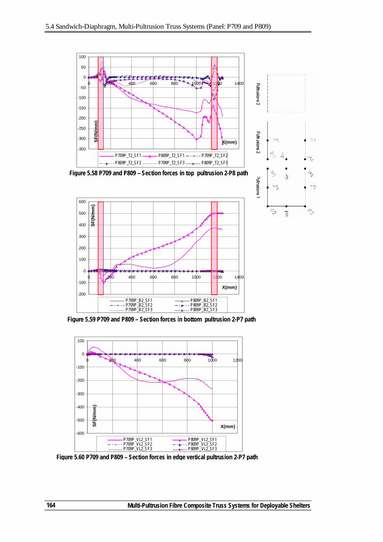
5.4 Sandwich-Diaphragm, Multi-Pultrusion Truss Systems (Panel: P709 and P809)
Multi-Pultrusion Fibre Composite Truss Systems for Deployable Shelters
164
-600
-500
-400
-300
-200
-100
0
100
0 200 400 600 800 1000 1200
X(mm)SF(N
/mm
)
P709P_VL2_SF1 P809P_VL2_SF1P709P_VL2_SF2 P809P_VL2_SF2P709P_VL2_SF3 P809P_VL2_SF3
Figure 5.60 P709 and P809 – Section forces in edge vertical pultrusion 2-P7 path
Figure 5.59 P709 and P809 – Section forces in bottom pultrusion 2-P7 path
-200
-100
0
100
200
300
400
500
600
0 200 400 600 800 1000 1200 1400
X(mm)
SF(N
/mm
)
P709P_B2_SF1 P809P_B2_SF1P709P_B2_SF2 P809P_B2_SF2P709P_B2_SF3 P809P_B2_SF3
-350
-300
-250
-200
-150
-100
-50
0
50
100
0 200 400 600 800 1000 1200 1400
X(mm)SF(N
/mm
)
P709P_T2_SF1 P809P_T2_SF1 P709P_T2_SF2P809P_T2_SF2 P709P_T2_SF3 P809P_T2_SF3
Figure 5.58 P709 and P809 – Section forces in top pultrusion 2-P8 path
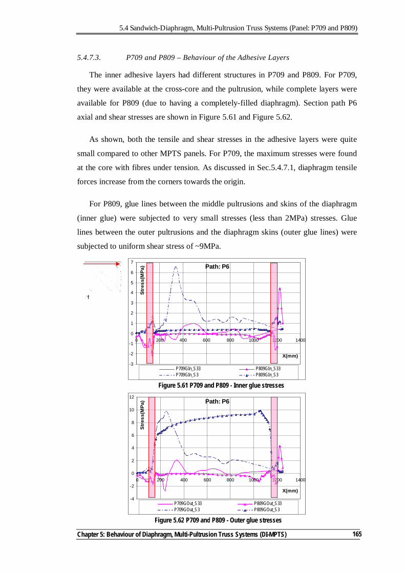
5.4 Sandwich-Diaphragm, Multi-Pultrusion Truss Systems (Panel: P709 and P809)
Chapter 5: Behaviour of Diaphragm, Multi-Pultrusion Truss Systems (DI-MPTS)
165
5.4.7.3. P709 and P809 – Behaviour of the Adhesive Layers
The inner adhesive layers had different structures in P709 and P809. For P709,
they were available at the cross-core and the pultrusion, while complete layers were
available for P809 (due to having a completely-filled diaphragm). Section path P6
axial and shear stresses are shown in Figure 5.61 and Figure 5.62.
As shown, both the tensile and shear stresses in the adhesive layers were quite
small compared to other MPTS panels. For P709, the maximum stresses were found
at the core with fibres under tension. As discussed in Sec.5.4.7.1, diaphragm tensile
forces increase from the corners towards the origin.
For P809, glue lines between the middle pultrusions and skins of the diaphragm
(inner glue) were subjected to very small stresses (less than 2MPa) stresses. Glue
lines between the outer pultrusions and the diaphragm skins (outer glue lines) were
subjected to uniform shear stress of ~9MPa.
Path: P6
-3
-2
-1
0
1
2
3
4
5
6
7
0 200 400 600 800 1000 1200 1400
X(mm)
Stre
ss(M
Pa)
P709GIn_S33 P809GIn_S33P709GIn_S3 P809GIn_S3
Figure 5.61 P709 and P809 - Inner glue stresses
Path: P6
-4
-2
0
2
4
6
8
10
12
0 200 400 600 800 1000 1200 1400
X(mm)
Stre
ss(M
Pa)
P709GOut_S33 P809GOut_S33P709GOut_S3 P809GOut_S3
Figure 5.62 P709 and P809 - Outer glue stresses
5.4 Sandwich-Diaphragm, Multi-Pultrusion Truss Systems (Panel: P709 and P809)
Multi-Pultrusion Fibre Composite Truss Systems for Deployable Shelters
166
5.4.7.4. P709 and P809 – General Behaviour
It was found that the introduction of the core significantly improved the panel
performance. The core eliminated the buckling of the skins and thus reduced the
associated secondary effects of having excessive curvatures. P709 was the only panel
to fail. After reaching its ultimate capacity, the panel continued to carry partial loads
with significant reserve in the panel system. P809 had the higher carrying capacity
with the highest stiffness. Sandwich construction distributed the resisting forces well
within both panels avoiding a concentration of stresses in the connecting parts with
significant reserve in the adhesive layers.
Clearly, P709 showed redundancy by loosing its capacity in steps (not in a
sudden brittle failure) without complete loss of its strength despite reaching
excessive displacement. Testing P809 did not reach its ultimate capacity and
accordingly the characteristics of its failure could not be judged. However, in
comparing the level of stresses in the different panel components of P809 & P309
(Sec 3.6.2.3, p67) the FE analysis results suggests that diaphragm skins is stressed to
45% of P309 (where failure occurred in P309), the adhesive layers 13% and the
pultrusions 72% (did not fail in both panels). With the stresses in pultusions reaching
90MPa, compared to its uni-directional capacity of 450MPa, Table 3.2 p37, failure is
not expected to occur in the pultrusions. Accordingly, failure of P809 is expected to
occur in the diaphragm skins.
5.5. MULTI-PULTRUSION TRUSS SYSTEMS - COMPARING THE DISCRETE-DIAGONAL AND DIAPHRAGM SYSTEMS
The development of the concept of MPTS detailed from Chapter 3 to Chapter 5
involved the investigation of two categories of panels; Discrete-Diagonal (DD) and
Diaphragm (DI). Both categories showed high load-carrying capacity, with the
allowance of load redundancy in reaching their ultimate capacity, except for DD with
diagonals under compression. In this section, the two systems are compared from the
perspective of structural performance, cost, weight, and future potential. Each of
these factors is discussed in a separate sub-section.
5.5 Multi-pultrusion Truss Systems - Comparing the Discrete-Diagonal and Diaphragm Systems
Chapter 5: Behaviour of Diaphragm, Multi-Pultrusion Truss Systems (DI-MPTS)
167
5.5.1. STRUCTURAL PERFORMANCE
The main difference between the two panel systems was the bracing system; with
confinement effects at corners as an important characteristic. However, its effect was
more apparent in DD and DI with no core material. The behaviour of the DD-MPTS
was simpler to predict and explain. The use of high-shear-modulus core material was
essential to the success of DD-MPTS. The diagonal compressive capacity, and
therefore the panel capacity, was highly affected by the core properties. The diagonal
confinement resulted in lateral forces of opposite sign to that in the diagonal
direction. Accordingly, the most critical load condition is with diagonals under
compression. This loading condition generated tensile stresses in the lateral direction
(with the least reinforcements) and accordingly reduced the laminate efficiency in
carrying loads in the diagonal direction. The overall buckling of the diagonal is
another characteristic of DD-MPTS. These characteristics can be managed as
structural behaviour of this panel behaviour can be accurately predicted.
In DI-MPTS the diaphragm forces were carried by the skins. The distribution of
these forces, and accordingly the panel capacity, were dependent on the level of
control of the buckling of the skins. With no core, the diaphragm acts as a tension-
only diaphragm, with most of the diaphragm forces carried by fibres under tension.
Buckling resulted in high secondary bending stresses, which significantly reduced
the axial load-carrying capacity of the laminate. With the introduction of a core to
form a sandwich diaphragm, the panel performance was significantly increased. The
use of a fully-filled diaphragm maximised the load-carrying capacity of the DI panel.
It was found that the panel performance was not very sensitive to the core material
used, permitting the use of low-shear-modulus (density) cores. The second important
feature of this system was the availability of alternative load paths through the
diaphragm which prevented complete loss of strength when the panel reached
ultimate capacity. However, this could not be judged for the fully filled diaphragm
panels as the tested panel capacity could not be reached during testing.
5.5.2. PANEL COSTS
There are many factors that can affect the manufacturing costs of the panels.
Material costs and labour costs need to be optimised. The manufacturing procedures
for both types of panels were traditional with no high technology or automated
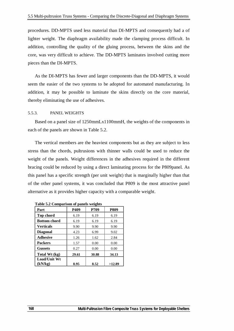
5.5 Multi-pultrusion Truss Systems - Comparing the Discrete-Diagonal and Diaphragm Systems
Multi-Pultrusion Fibre Composite Truss Systems for Deployable Shelters
168
procedures. DD-MPTS used less material than DI-MPTS and consequently had a of
lighter weight. The diaphragm availability made the clamping process difficult. In
addition, controlling the quality of the gluing process, between the skins and the
core, was very difficult to achieve. The DD-MPTS laminates involved cutting more
pieces than the DI-MPTS.
As the DI-MPTS has fewer and larger components than the DD-MPTS, it would
seem the easier of the two systems to be adopted for automated manufacturing. In
addition, it may be possible to laminate the skins directly on the core material,
thereby eliminating the use of adhesives.
5.5.3. PANEL WEIGHTS
Based on a panel size of 1250mmLx1100mmH, the weights of the components in
each of the panels are shown in Table 5.2.
The vertical members are the heaviest components but as they are subject to less
stress than the chords, pultrusions with thinner walls could be used to reduce the
weight of the panels. Weight differences in the adhesives required in the different
bracing could be reduced by using a direct laminating process for the P809panel. As
this panel has a specific strength (per unit weight) that is marginally higher than that
of the other panel systems, it was concluded that P809 is the most attractive panel
alternative as it provides higher capacity with a comparable weight.
Table 5.2 Comparison of panels weights Part P409 P709 P809 Top chord 6.19 6.19 6.19 Bottom chord 6.19 6.19 6.19 Verticals 9.90 9.90 9.90 Diagonal 4.23 6.99 9.02 Adhesive 1.26 1.62 2.84 Packers 1.57 0.00 0.00 Gussets 0.27 0.00 0.00 Total Wt (kg) 29.61 30.88 34.13 Load/Unit Wt (kN/kg) 8.95 8.52 >12.89
5.6 Conclusions
Chapter 5: Behaviour of Diaphragm, Multi-Pultrusion Truss Systems (DI-MPTS)
169
5.6. CONCLUSIONS
The concept of Diaphragm MPTS was developed and investigated in this chapter.
The DI-MPTS concept was based on using double skins, replacing the discrete
diagonal sandwich member. Using diaphragms with no core material led to excessive
buckling which reduced the load-carrying capacity of the panel.
In introducing the core material to form a sandwich web, the diaphragm forces
were shared between fibres in both directions (under compression and tension).
Increasing the percentage of core material distributed the forces evenly and
accordingly led to having panels with very high load-carrying capacity. The
diaphragm eliminated the concentration of stresses in other components. This was
due to the continuous transfer of forces at the diaphragm interface. The other main
advantage of this system was providing significant redundancy in the system that
prevented the occurrence of complete loss of strength in reaching the ultimate
capacity. This panel system was more difficult to manufacture, using the current
procedures. However, it has more potential for developing an automated process that
can reduce its weight as well.
The finite element models used to predict the panel behaviour were efficient tools
to investigate their behaviour. For the different panel systems, the FE closely
predicted both the load-deflection and strain-load behaviour. Accordingly, these
models can be used to verify the efficiency of the macro-level models which can be
used to conduct complete-frame analysis.
In Chapter 6, simplified modelling procedures are proposed to allow the
prediction of the panel behaviour within the overall frame analysis. These procedures
will be verified with the FE modelling procedures presented in Chapter 3 to Chapter
5 to ensure their suitability.
5.7. REFERENCES
ATL Composites Homepage. http://www.atlcomposites.com.au. Colan Homepage. http://www.colan.com.au.
Pacific Composites Homepage. http://www.pacomp.com.au/. Rogers, D. (2004). Characterisation of Hyrez 201 laminating resin. Polymer Testing
Laboratory, University of Southern Queensland, Toowoomba, Queensland.

Multi-Pultrusion Fibre Composite Truss Systems for Deployable Shelters
170
Chapter 6 Notations
A Equivalent beam section cross sectional area
As Equivalent beam section shear area
E1 Tensile modulus in the 1-1 (fibre) direction
G Equivalent beam section shear modulus
G12 Shear modulus in the 1-2 plane
I Equivalent beam section second moment of area
6.1 Introduction
Chapter 6: Simplified Analysis for the Multi-Pultrusion Truss Systems (MPTS)
171
6. Simplified Analysis Models for the Multi-Pultrusion Truss
Systems (MPTS)
6.1. INTRODUCTION
In this thesis, the concept of a multi-pultrusion truss system (MPTS) has been
developed using either the discrete-diagonal (DD) or the diaphragm (DI) bracing
system. FE modelling procedures were used to predict the behaviour of both panel
types at micro level. The FE models simulated the behaviour of the tested panels
well. This led to developing a basic understanding of these behaviours, Chapter 3 to
Chapter 5.
Due to their detailed nature, the micro FE models are time-consuming, both in
preparing the models and in analysing them. In addition, reasonably high
computational power is required. This necessitates the development of simplified
modelling procedures at macro level. A macro model can be a valuable tool in two
ways. The first is optimising the panel layout then conducting micro-model analysis
on the optimum configuration. The second is conducting overall frame analysis
which is important for practising engineers who are interested in using the MPTS.
Thus, the macro models should be, practically, easy-to-model and provide good
prediction of the panel behaviour.
This chapter focuses on the simplification of modelling procedures. After
addressing the important behavioural aspects to be considered, the simplified
modelling concepts of DD-MPTS and DI-MPTS are presented. To validate these
simplification procedures, the macro models analysis results were correlated to their
micro-models counterparts, for DD-MPTS (P409, Chapter 4) and DI-MPTS (P809,
Chapter 5). The chapter concludes with general recommendations for the simplified
modelling procedures.
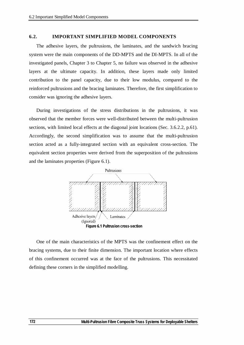
6.2 Important Simplified Model Components
Multi-Pultrusion Fibre Composite Truss Systems for Deployable Shelters
172
6.2. IMPORTANT SIMPLIFIED MODEL COMPONENTS
The adhesive layers, the pultrusions, the laminates, and the sandwich bracing
system were the main components of the DD-MPTS and the DI-MPTS. In all of the
investigated panels, Chapter 3 to Chapter 5, no failure was observed in the adhesive
layers at the ultimate capacity. In addition, these layers made only limited
contribution to the panel capacity, due to their low modulus, compared to the
reinforced pultrusions and the bracing laminates. Therefore, the first simplification to
consider was ignoring the adhesive layers.
During investigations of the stress distributions in the pultrusions, it was
observed that the member forces were well-distributed between the multi-pultrusion
sections, with limited local effects at the diagonal joint locations (Sec. 3.6.2.2, p.61).
Accordingly, the second simplification was to assume that the multi-pultrusion
section acted as a fully-integrated section with an equivalent cross-section. The
equivalent section properties were derived from the superposition of the pultrusions
and the laminates properties (Figure 6.1).
One of the main characteristics of the MPTS was the confinement effect on the
bracing systems, due to their finite dimension. The important location where effects
of this confinement occurred was at the face of the pultrusions. This necessitated
defining these corners in the simplified modelling.
Figure 6.1 Pultrusion cross-section
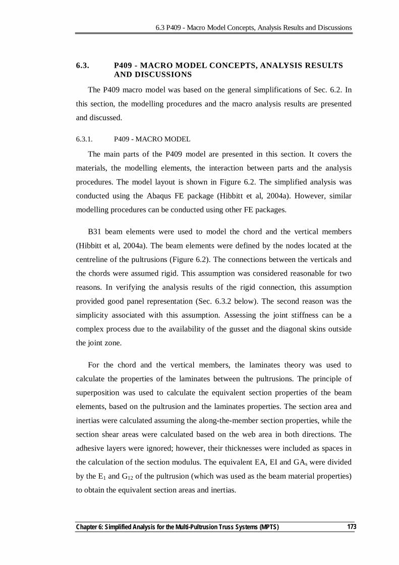
6.3 P409 - Macro Model Concepts, Analysis Results and Discussions
Chapter 6: Simplified Analysis for the Multi-Pultrusion Truss Systems (MPTS)
173
6.3. P409 - MACRO MODEL CONCEPTS, ANALYSIS RESULTS AND DISCUSSIONS
The P409 macro model was based on the general simplifications of Sec. 6.2. In
this section, the modelling procedures and the macro analysis results are presented
and discussed.
6.3.1. P409 - MACRO MODEL
The main parts of the P409 model are presented in this section. It covers the
materials, the modelling elements, the interaction between parts and the analysis
procedures. The model layout is shown in Figure 6.2. The simplified analysis was
conducted using the Abaqus FE package (Hibbitt et al, 2004a). However, similar
modelling procedures can be conducted using other FE packages.
B31 beam elements were used to model the chord and the vertical members
(Hibbitt et al, 2004a). The beam elements were defined by the nodes located at the
centreline of the pultrusions (Figure 6.2). The connections between the verticals and
the chords were assumed rigid. This assumption was considered reasonable for two
reasons. In verifying the analysis results of the rigid connection, this assumption
provided good panel representation (Sec. 6.3.2 below). The second reason was the
simplicity associated with this assumption. Assessing the joint stiffness can be a
complex process due to the availability of the gusset and the diagonal skins outside
the joint zone.
For the chord and the vertical members, the laminates theory was used to
calculate the properties of the laminates between the pultrusions. The principle of
superposition was used to calculate the equivalent section properties of the beam
elements, based on the pultrusion and the laminates properties. The section area and
inertias were calculated assuming the along-the-member section properties, while the
section shear areas were calculated based on the web area in both directions. The
adhesive layers were ignored; however, their thicknesses were included as spaces in
the calculation of the section modulus. The equivalent EA, EI and GAs were divided
by the E1 and G12 of the pultrusion (which was used as the beam material properties)
to obtain the equivalent section areas and inertias.
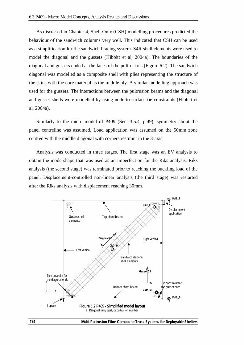
6.3 P409 - Macro Model Concepts, Analysis Results and Discussions
Multi-Pultrusion Fibre Composite Truss Systems for Deployable Shelters
174
As discussed in Chapter 4, Shell-Only (CSH) modelling procedures predicted the
behaviour of the sandwich columns very well. This indicated that CSH can be used
as a simplification for the sandwich bracing system. S4R shell elements were used to
model the diagonal and the gussets (Hibbitt et al, 2004a). The boundaries of the
diagonal and gussets ended at the faces of the pultrusions (Figure 6.2). The sandwich
diagonal was modelled as a composite shell with plies representing the structure of
the skins with the core material as the middle ply. A similar modelling approach was
used for the gussets. The interactions between the pultrusion beams and the diagonal
and gusset shells were modelled by using node-to-surface tie constraints (Hibbitt et
al, 2004a).
Similarly to the micro model of P409 (Sec. 3.5.4, p.49), symmetry about the
panel centreline was assumed. Load application was assumed on the 50mm zone
centred with the middle diagonal with corners restraint in the 3-axis.
Analysis was conducted in three stages. The first stage was an EV analysis to
obtain the mode shape that was used as an imperfection for the Riks analysis. Riks
analysis (the second stage) was terminated prior to reaching the buckling load of the
panel. Displacement-controlled non-linear analysis (the third stage) was restarted
after the Riks analysis with displacement reaching 30mm.
Displacement application
Left vertical
Top chord beams Gusset shell elements
Sandwich diagonal shell elements
Support Figure 6.2 P409 - Simplified model layout ?: Diagonal skin, gust, or pultrusion number
Tie constraint for the diagonal ends
Bottom chord beams Tie constraint for the gusset ends
Right vertical
Dia?_M
Pul?_T
Pul?_B
Gst?_M
Dia?_E
Diagonal CS
Gusset CS
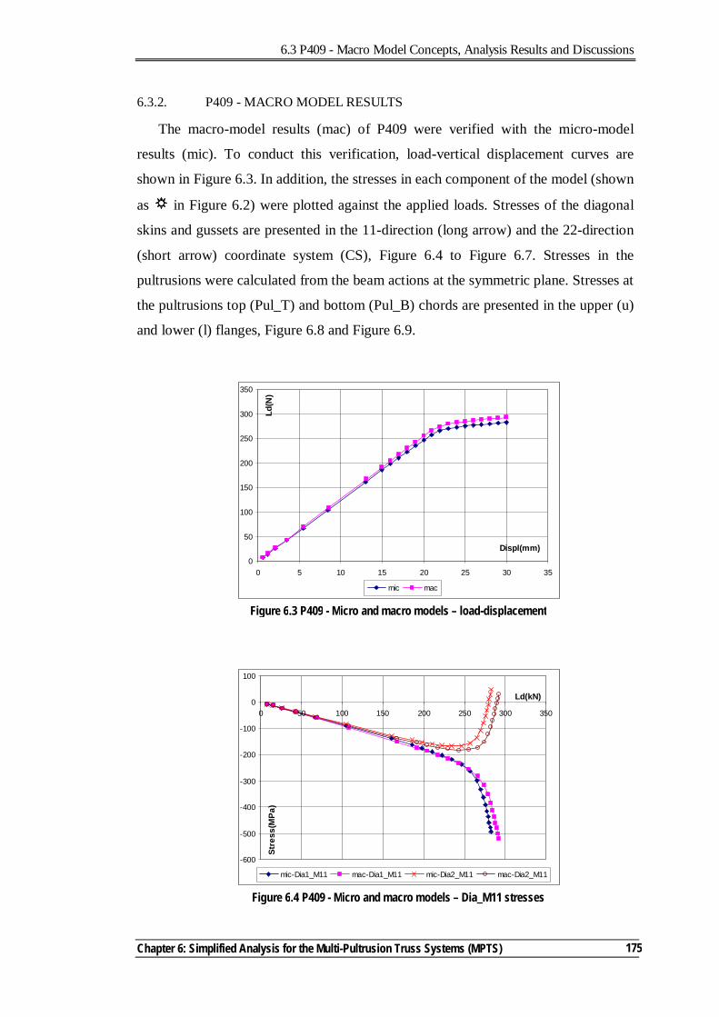
6.3 P409 - Macro Model Concepts, Analysis Results and Discussions
Chapter 6: Simplified Analysis for the Multi-Pultrusion Truss Systems (MPTS)
175
6.3.2. P409 - MACRO MODEL RESULTS
The macro-model results (mac) of P409 were verified with the micro-model
results (mic). To conduct this verification, load-vertical displacement curves are
shown in Figure 6.3. In addition, the stresses in each component of the model (shown
as in Figure 6.2) were plotted against the applied loads. Stresses of the diagonal
skins and gussets are presented in the 11-direction (long arrow) and the 22-direction
(short arrow) coordinate system (CS), Figure 6.4 to Figure 6.7. Stresses in the
pultrusions were calculated from the beam actions at the symmetric plane. Stresses at
the pultrusions top (Pul_T) and bottom (Pul_B) chords are presented in the upper (u)
and lower (l) flanges, Figure 6.8 and Figure 6.9.
Figure 6.3 P409 - Micro and macro models – load-displacement
0
50
100
150
200
250
300
350
0 5 10 15 20 25 30 35
Displ(mm)
Ld(N
)
mic mac
Figure 6.4 P409 - Micro and macro models – Dia_M11 stresses
-600
-500
-400
-300
-200
-100
0
100
0 50 100 150 200 250 300 350
Ld(kN)
Stre
ss(M
Pa)
mic-Dia1_M11 mac-Dia1_M11 mic-Dia2_M11 mac-Dia2_M11
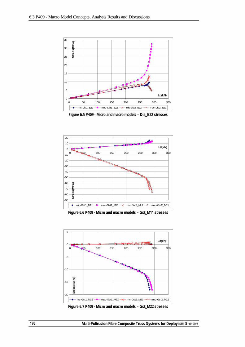
6.3 P409 - Macro Model Concepts, Analysis Results and Discussions
Multi-Pultrusion Fibre Composite Truss Systems for Deployable Shelters
176
Figure 6.5 P409 - Micro and macro models – Dia_E22 stresses
0
5
10
15
20
25
30
35
0 50 100 150 200 250 300 350
Ld(kN)
Stre
ss(M
Pa)
mic-Dia1_E22 mac-Dia1_E22 mic-Dia2_E22 mac-Dia2_E22
Figure 6.6 P409 - Micro and macro models – Gst_M11 stresses
-90
-80
-70
-60
-50
-40
-30
-20
-10
0
10
20
0 50 100 150 200 250 300 350
Ld(kN)
Stre
ss(M
Pa)
mic-Gst1_M11 mac-Gst1_M11 mic-Gst2_M11 mac-Gst2_M11
Figure 6.7 P409 - Micro and macro models – Gst_M22 stresses
-20
-15
-10
-5
0
5
0 50 100 150 200 250 300 350
Ld(kN)
Stre
ss(M
Pa)
mic-Gst1_M22 mac-Gst1_M22 mic-Gst2_M22 mac-Gst2_M22
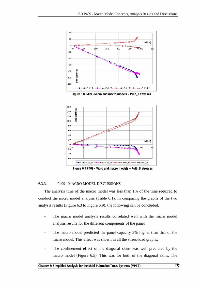
6.3 P409 - Macro Model Concepts, Analysis Results and Discussions
Chapter 6: Simplified Analysis for the Multi-Pultrusion Truss Systems (MPTS)
177
6.3.3. P409 - MACRO MODEL DISCUSSIONS
The analysis time of the macro model was less than 1% of the time required to
conduct the micro model analysis (Table 6.1). In comparing the graphs of the two
analysis results (Figure 6.3 to Figure 6.9), the following can be concluded:
- The macro model analysis results correlated well with the micro model
analysis results for the different components of the panel.
- The macro model predicted the panel capacity 3% higher than that of the
micro model. This effect was shown in all the stress-load graphs.
- The confinement effect of the diagonal skins was well predicted by the
macro model (Figure 6.5). This was for both of the diagonal skins. The
Figure 6.8 P409 - Micro and macro models – Pul2_T stresses
-120
-100
-80
-60
-40
-20
0
20
40
0 50 100 150 200 250 300 350
Ld(kN)
Stre
ss(M
Pa)
mic-Pul2_Tu mac-Pul2_Tu mic-Pul2_Tl mac-Pul2_Tl
Figure 6.9 P409 - Micro and macro models – Pul2_B stresses
-60
-40
-20
0
20
40
60
80
100
120
140
160
0 50 100 150 200 250 300 350
Ld(kN)
Stre
ss(M
Pa)
mic-Pul2_Bu mac-Pul2_Bu mic-Pul2_Bl mac-Pul2_Bl
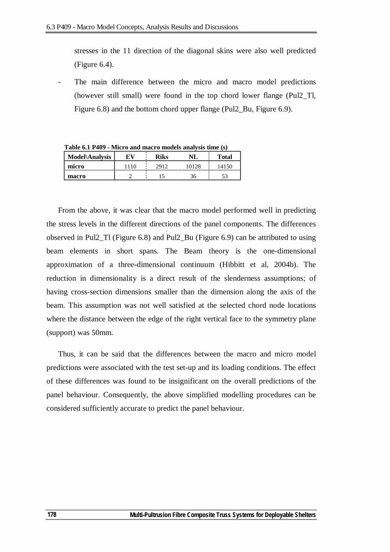
6.3 P409 - Macro Model Concepts, Analysis Results and Discussions
Multi-Pultrusion Fibre Composite Truss Systems for Deployable Shelters
178
stresses in the 11 direction of the diagonal skins were also well predicted
(Figure 6.4).
- The main difference between the micro and macro model predictions
(however still small) were found in the top chord lower flange (Pul2_Tl,
Figure 6.8) and the bottom chord upper flange (Pul2_Bu, Figure 6.9).
Table 6.1 P409 - Micro and macro models analysis time (s) Model\Analysis EV Riks NL Total micro 1110 2912 10128 14150 macro 2 15 36 53
From the above, it was clear that the macro model performed well in predicting
the stress levels in the different directions of the panel components. The differences
observed in Pul2_Tl (Figure 6.8) and Pul2_Bu (Figure 6.9) can be attributed to using
beam elements in short spans. The Beam theory is the one-dimensional
approximation of a three-dimensional continuum (Hibbitt et al, 2004b). The
reduction in dimensionality is a direct result of the slenderness assumptions; of
having cross-section dimensions smaller than the dimension along the axis of the
beam. This assumption was not well satisfied at the selected chord node locations
where the distance between the edge of the right vertical face to the symmetry plane
(support) was 50mm.
Thus, it can be said that the differences between the macro and micro model
predictions were associated with the test set-up and its loading conditions. The effect
of these differences was found to be insignificant on the overall predictions of the
panel behaviour. Consequently, the above simplified modelling procedures can be
considered sufficiently accurate to predict the panel behaviour.
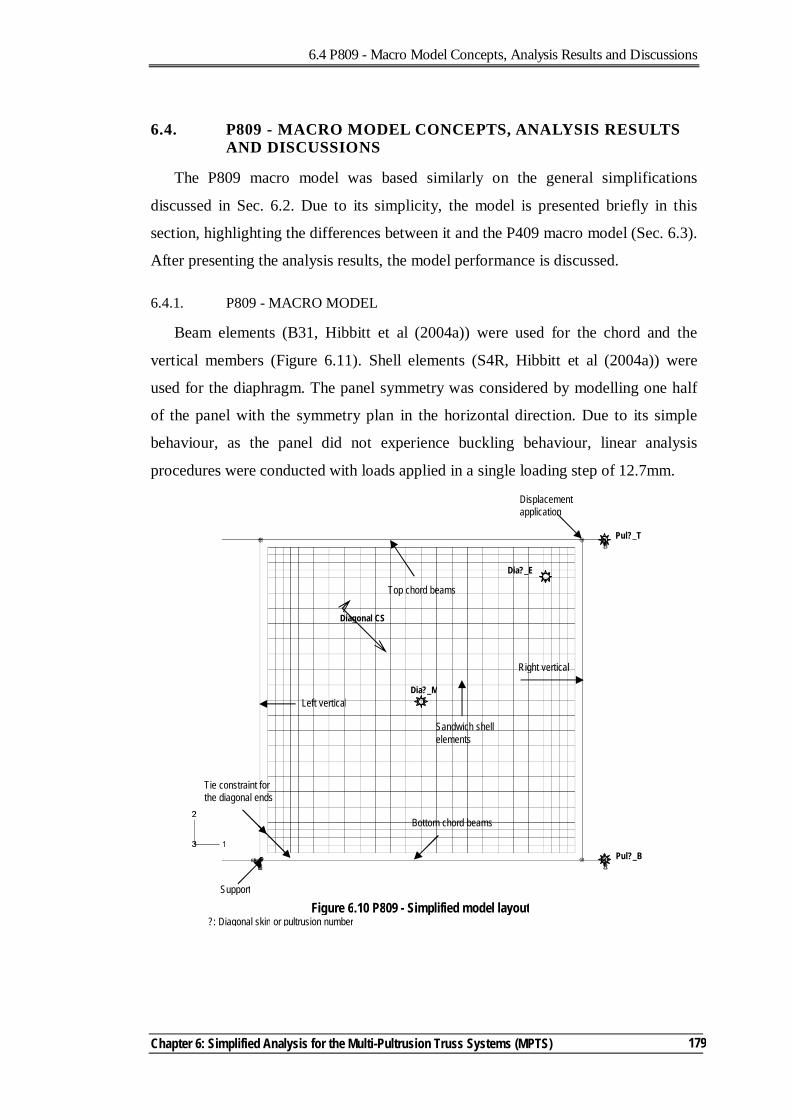
6.4 P809 - Macro Model Concepts, Analysis Results and Discussions
Chapter 6: Simplified Analysis for the Multi-Pultrusion Truss Systems (MPTS)
179
6.4. P809 - MACRO MODEL CONCEPTS, ANALYSIS RESULTS AND DISCUSSIONS
The P809 macro model was based similarly on the general simplifications
discussed in Sec. 6.2. Due to its simplicity, the model is presented briefly in this
section, highlighting the differences between it and the P409 macro model (Sec. 6.3).
After presenting the analysis results, the model performance is discussed.
6.4.1. P809 - MACRO MODEL
Beam elements (B31, Hibbitt et al (2004a)) were used for the chord and the
vertical members (Figure 6.11). Shell elements (S4R, Hibbitt et al (2004a)) were
used for the diaphragm. The panel symmetry was considered by modelling one half
of the panel with the symmetry plan in the horizontal direction. Due to its simple
behaviour, as the panel did not experience buckling behaviour, linear analysis
procedures were conducted with loads applied in a single loading step of 12.7mm.
Displacement application
Left vertical
Top chord beams
Sandwich shell elements
Support
Figure 6.10 P809 - Simplified model layout ?: Diagonal skin or pultrusion number
Tie constraint for the diagonal ends
Bottom chord beams
Right vertical
Dia?_M
Pul?_T
Pul?_B
Dia?_E
Diagonal CS
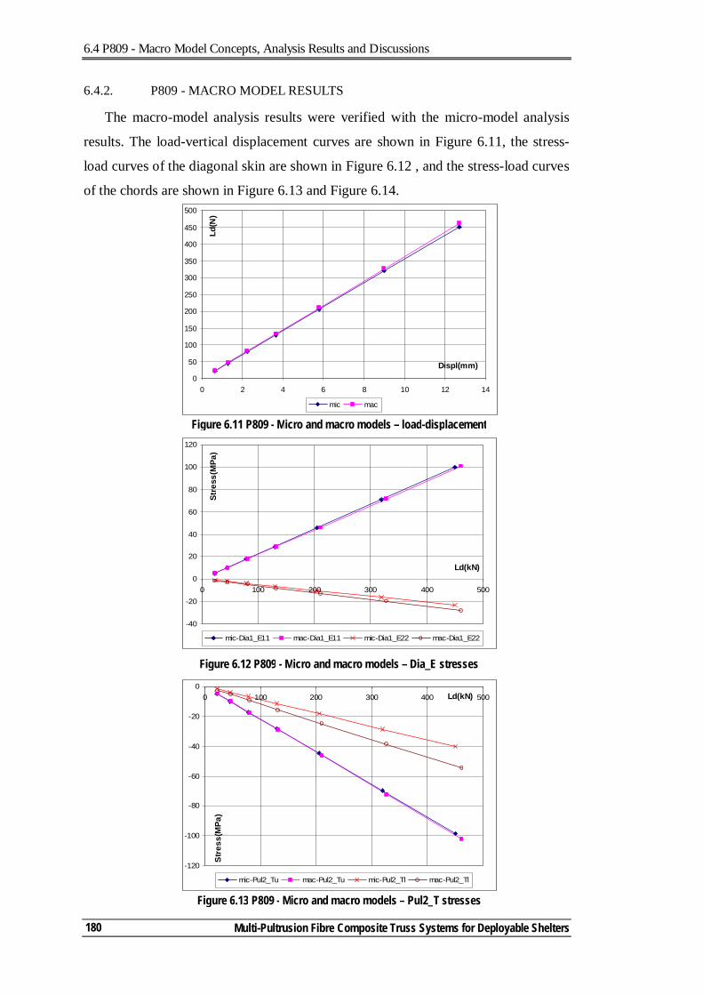
6.4 P809 - Macro Model Concepts, Analysis Results and Discussions
Multi-Pultrusion Fibre Composite Truss Systems for Deployable Shelters
180
6.4.2. P809 - MACRO MODEL RESULTS
The macro-model analysis results were verified with the micro-model analysis
results. The load-vertical displacement curves are shown in Figure 6.11, the stress-
load curves of the diagonal skin are shown in Figure 6.12 , and the stress-load curves
of the chords are shown in Figure 6.13 and Figure 6.14.
0
50
100
150
200
250
300
350
400
450
500
0 2 4 6 8 10 12 14
Displ(mm)
Ld(N
)
mic mac
Figure 6.11 P809 - Micro and macro models – load-displacement
-40
-20
0
20
40
60
80
100
120
0 100 200 300 400 500
Ld(kN)
Stre
ss(M
Pa)
mic-Dia1_E11 mac-Dia1_E11 mic-Dia1_E22 mac-Dia1_E22
Figure 6.12 P809 - Micro and macro models – Dia_E stresses
-120
-100
-80
-60
-40
-20
00 100 200 300 400 500Ld(kN)
Stre
ss(M
Pa)
mic-Pul2_Tu mac-Pul2_Tu mic-Pul2_Tl mac-Pul2_Tl
Figure 6.13 P809 - Micro and macro models – Pul2_T stresses
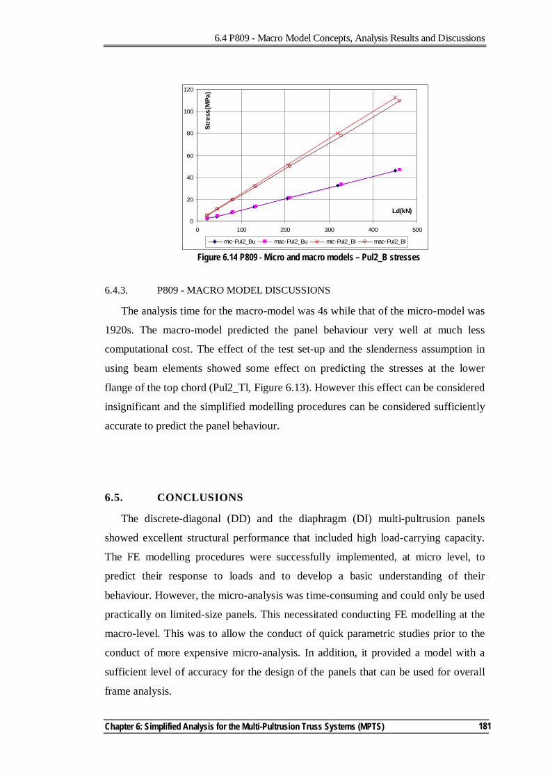
6.4 P809 - Macro Model Concepts, Analysis Results and Discussions
Chapter 6: Simplified Analysis for the Multi-Pultrusion Truss Systems (MPTS)
181
6.4.3. P809 - MACRO MODEL DISCUSSIONS
The analysis time for the macro-model was 4s while that of the micro-model was
1920s. The macro-model predicted the panel behaviour very well at much less
computational cost. The effect of the test set-up and the slenderness assumption in
using beam elements showed some effect on predicting the stresses at the lower
flange of the top chord (Pul2_Tl, Figure 6.13). However this effect can be considered
insignificant and the simplified modelling procedures can be considered sufficiently
accurate to predict the panel behaviour.
6.5. CONCLUSIONS
The discrete-diagonal (DD) and the diaphragm (DI) multi-pultrusion panels
showed excellent structural performance that included high load-carrying capacity.
The FE modelling procedures were successfully implemented, at micro level, to
predict their response to loads and to develop a basic understanding of their
behaviour. However, the micro-analysis was time-consuming and could only be used
practically on limited-size panels. This necessitated conducting FE modelling at the
macro-level. This was to allow the conduct of quick parametric studies prior to the
conduct of more expensive micro-analysis. In addition, it provided a model with a
sufficient level of accuracy for the design of the panels that can be used for overall
frame analysis.
0
20
40
60
80
100
120
0 100 200 300 400 500
Ld(kN)St
ress
(MPa
)
mic-Pul2_Bu mac-Pul2_Bu mic-Pul2_Bl mac-Pul2_Bl
Figure 6.14 P809 - Micro and macro models – Pul2_B stresses
6.5 Conclusions
Multi-Pultrusion Fibre Composite Truss Systems for Deployable Shelters
182
The macro-models were based on using beam elements for the chord and vertical
members and shell elements for the gussets, diagonals and diaphragms. The shell
elements boundaries were formed by the faces of the connected members, while the
beam elements were located at the centreline of the related members. The beam
elements constrained the adjacent shell elements by using node-to-surface tie
constraints. Similar to the micro-model, analyses were conducted in three stages for
the DD panel. To predict the buckling behaviour of the panel (i) Eigen-Value
analysis was conducted to obtain the panel mode shape. The mode shape was used as
an imperfection in (ii) Riks analysis, reaching a load level lower than the buckling
capacity of the panel. Then (iii) non-linear displacement-controlled analysis was used
until reaching the required displacement. DI panel analysis was a single-step linear
analysis.
The macro-model predicted very well the behaviour of the different panel
components. The only difference in predictions was found in the lower flange of the
top chord. This was attributed to not fully satisfying the slenderness assumption for
using beam elements. However, this difference can be considered insignificant as it
was related to the test set-up.
6.6. REFERENCES
Hibbitt, Karlsson & Sorensen Inc. (2004a). ABAQUS Analysis user's manual. Hibbitt, Karlsson & Sorensen Inc. (2004b). ABAQUS Theory manual.
7.1 Introduction
Chapter 7: Conclusions and Suggestions for Further Research Work
183
7. Conclusions and Suggestions for Further Research Work
7.1. INTRODUCTION
Deployable shelters are an important sub-set of deployable structures that can be
used for military and/or civil applications. The M2S2 deployable shelter system is a
further development of the stressed-arch concept implemented by Strarch in their
steel frames. The M2S2 research programme aims to extend the existing Strarch
concept into a system with dramatically improved deployment characteristics. This
study was not a research project that had pre-defined research outcomes. It was the
first to investigate the concept of M2S2, a fibre composite re-deployable curved
shelter system, and a number of important aspects had to be addressed prior to
conducting detailed investigations. These include reviewing available deployable
shelter systems, investigating the deployability requirements, assessing the loading
criteria and the member forces, exploring the structural systems for composite
trusses, investigating different modular panel alternatives that suit the concept of
M2S2 and then developing an understanding of the main behavioural issues of these
alternatives.
Conclusions presented in this chapter are divided into three parts. The first part
relates to the different structural systems of the composite trusses, concluding with
the main behavioural aspects of the multi-pultrusion truss system (MPTS). The
second part relates to the FE modelling of the MPTS, both at the micro-level and the
macro-level. The third part relates to general conclusions observed from the course
of this study. The chapter closes with suggestions for further research work.
7.2 Structural Systems for Composite Trusses
Multi-Pultrusion Fibre Composite Truss Systems for Deployable Shelters
184
7.2. STRUCTURAL SYSTEMS FOR COMPOSITE TRUSSES
Fibre composites are relatively new materials for use in civil engineering
applications. Their unique nature and flexibility add complexity to their application
as a construction material when compared to traditionally-used timber, steel and
concrete. Based on the literature review and the investigations conducted during this
study, the main conclusions regarding the fibre composite truss systems can be
summarised as:
- In conventional truss systems, the use of pultruded sections with bolted
and/or adhesive joints limits the full mobilisation of the fibre composite
materials used. The use of these systems can be justified, as the serviceability
limit state of deflection and/or durability can be the governing limit states,
and accordingly, the pultrusions used are not usually stressed to their limit.
- Due to the arch-shaped geometry of M2S2 frames, the deflection of the frames
is not a governing limit state. In addition, the frame members carry high
forces. Thus following the conventional truss system will provide inefficient
uneconomical solution.
- In a bonded joint, the properties of the adhesive, the adherent and the joint
geometry significantly affect the joint capacity and mode of failure. In
general, using higher inter-laminar shear resins along with stiffer and thinner
adherents and symmetric joint lay-up, improve the joint capacity. However,
the use of gussets in the truss joints limits the improvement in its capacity due
to the concentration of stresses associated with transferring all the bracing
member forces through the gusset.
- In this study, this limitation was overcome by introducing the concept of
Multi-Pultrusion Truss System (MPTS). In this system, the chord members
(which usually carry more forces compared with other members) and the
vertical members were formed from a number of pultrusions in a plane-truss
construction, with two alternatives for the sandwich bracing system.
- In the MPTS, the use of gussets was eliminated by extending the skins of the
sandwich bracing between the pultrusion members in adhesively bonded
joints. This modification had many advantages: (i) direct force transfer
7.2 Structural Systems for Composite Trusses
Chapter 7: Conclusions and Suggestions for Further Research Work
185
between the truss members, (ii) the skins functioned as the gusset plate to join
the vertical members to the chord members, (iii) provided continuous media
of adhesive layers which reduced the stress concentrations in the adhesion
significantly, and (iv) the joint layout was favourable in having a double-lap
joint between each two-pultrusions with rigid box-section adherents.
- In all of the tested MPTS, the ultimate capacity failure occurred in the
bracing system. This means that the composites were utilised to their limit
with the advantage of achieving controlled failure mode.
- Both of the MPTS alternatives had a high load-carrying capacity with a very
well predictable behaviour. The tested panels had structural redundancy, as
alternative load paths were formed once reaching the ultimate capacity.
- The main characteristic of the MPTS was the confinement effect of the
bracing system between the adjacent vertical and chord members. This
generated bi-axial forces, of opposite sign, which led to failure initiation and
propagation in the skins of the bracing system.
- The Discrete-Diagonal Multi-Pultrusions Truss System (DD-MPTS) was the
first system to be investigated. When the panel diagonals were under tension,
lateral compression stresses were generated at the corners, due to the
confinement effect. In this loading condition, the system had redundancy.
After reaching the ultimate capacity, the skins of one of the diagonals failed
partially, by rupturing of its fibres under the bi-axial stress condition. This led
to losing part of its strength. Increasing the applied loads utilised the strength
of the undamaged side of the skins until reaching the point of final failure.
- When the diagonals were under compression, the core material of the
diagonal was identified as the critical factor in defining the panel capacity as
failure occurred by global shear buckling. This was the only loading
condition where sudden failure occurred. However, this failure mode was
predicted accurately by using the FE modelling and/or the analytical
equations (for sandwich columns assuming clamped-end conditions).
- The Diaphragm Multi-Pultrusions Truss System (DI-MPTS) was the second
alternative to be investigated. Using diaphragms with no core material led to
excessive buckling, which generated secondary bending stresses. This
7.2 Structural Systems for Composite Trusses
Multi-Pultrusion Fibre Composite Truss Systems for Deployable Shelters
186
reduced the load-carrying capacity of the panel, with forces concentrated
within the central half of the diaphragm. In this set-up, the diaphragm
behaved as a tension-only membrane with confined compressive stresses
which initiated failure at the diaphragm corners.
- When the core material was introduced to form a sandwich bracing system,
the diaphragm forces were evenly shared between compression and tensile
directions. This resulted in panels with a very high load-carrying capacity.
The concentration of stresses in the other components were eliminated due to
the continuous transfer of forces at the diaphragm interface.
- The continuous nature of the diaphragm provided significant redundancy in
the panel system that prevented the occurrence of complete loss of strength in
reaching the ultimate capacity.
- The structural performance of the MPTS can be attributed to loading each of
their components in its strength direction. This system maximised the
advantages of using fibre composites in a new truss system.
7.3. MODELLING CONSIDERATIONS OF THE MPTS
Two levels of FE analyses were conducted during this study. The micro-model
analysis enabled the development of a basic understanding of the behaviour of the
DD-MPTS and the DI-MPTS. The macro-model analysis established simplified
modelling procedures that can be used as a preliminary to the more expensive micro-
analysis (to set the different panel parameters) and for the overall analysis of frames
of these panel types. The main modelling recommendations at these two levels are
detailed in Sec 7.3.1 and Sec. 7.3.2.
7.3.1. FE MICRO MODEL
- Three-dimensional thick shell elements provided good representation for the
pultrusions, the diagonal skins, the gussets and the packers between the
pultrusions.
- Reduced-integration shell element models delivered solutions at slightly less
cost compared to full-integration shell models with the same accuracy level.
7.3 Modelling Considerations of the MPTS
Chapter 7: Conclusions and Suggestions for Further Research Work
187
- Due to the closed shape of the pultrusions, it was necessary to compensate for
the overlapping effect of the shells at corners by using an equivalent shell
thickness.
- Core material and adhesive layers were modelled using reduced-integration
second-order solid continuum elements.
- Surface-to-surface and node-to-surface tie constraints were found to be a
convenient modelling practice to join each of the model parts.
- For the DD-MPTS with diagonals under compression, analysis needed to be
conducted in three steps. The imperfection was introduced to the model by
retrieving the nodal modal shape from Eigen-Value analysis. Then arc-length
(Riks) analysis was conducted on this imperfect geometry. Due to having
both the load and displacement as unknowns, Riks analysis was terminated
prior to reaching the buckling capacity of the panel, when geometrically
nonlinear analysis was then used with controlled displacement.
- The no-core DI-MPTS was found to be a highly nonlinear problem. However,
three steps analysis procedures provided good representation of the panel
behaviour.
- An alternative analysis approach was established by introducing imperfection
by applying a disturbing displacement to the centre of the diaphragm in the
first step. Then this displacement was released in the second step where the
main loads were applied. This alternative was found more efficient to
analyse, compared to Riks analysis. However, the accuracy of the analysis
was found to be dependent on the level of applied imperfection. In general, an
imperfection that at least equalled the thickness of the shell elements
provided reasonably accurate results.
- Due to its nature, as a shear wall, the DI-MPTS panel with complete core
filling was accurately modelled using linear analysis procedures.
7.3.2. FE MACRO MODEL
- Three-dimensional beam elements were used for the chord and the vertical
members.
7.3 Modelling Considerations of the MPTS
Multi-Pultrusion Fibre Composite Truss Systems for Deployable Shelters
188
- The assumption of a rigid connection between the vertical member ends and
the chord members was found to be satisfactory. In addition, it simplified the
modelling procedures.
- Three-dimensional thick shell elements were used for the gussets, the
diagonals and the diaphragms.
- The shell elements boundaries were formed by the faces of the connected
members, while the beam elements were defined at the centreline of the
related members.
- The beam elements constrained the adjacent shell elements by using node-to-
surface tie constraints.
- Similar to the micro-model, analyses were conducted in three stages for the
DD-MPTS while single-step linear analysis was conducted for the DI-MPTS
panel.
- The macro-model predicted very well the behaviour of the different panel
components. The only difference with the micro-model predictions was found
in the lower flange of the top chord. This was attributed to not fully satisfying
the slenderness assumption for using beam elements. This difference can be
considered insignificant as it was related to the test set-up.
7.4. GENERAL CONCLUSIONS
The general conclusions related to the current investigations are summarised as
follows:
- Frame-supported shelter systems are the most commonly-used systems for
deployable shelters with reasonably free spans. The concept of prestressed
arch technology was found to be unique. None of the identified systems used
fibre composite materials for the main frames.
- Good practice in the development and implementation of fibre composite
systems is to use as many standard components as possible, simplify the
concept with the least force transfers, avoid concentration of stresses, and to
exploit the unique properties of composite materials. Simulating technologies
7.4 General Conclusions
Chapter 7: Conclusions and Suggestions for Further Research Work
189
used with other construction materials can result in expensive, inefficient,
structural composite systems.
- The MPTS was simple to manufacture, with few system components, and
easy to analyse, once establishing the analysis procedures. It utilised the
characteristics of fibre composites and achieved good structural performance.
In addition, the system behaviour was insensitive to minor manufacturing
defects, tolerating some variance in production and further reduction in the
associated manufacturing costs.
- The intentions to model the failure process of the DD-MPTS were replaced
by further development of the concept of the DI-MPTS. This was mainly due
to the limitations in predicting the failure and post-failure behaviour of fibre
composites using the available analysis tools and theories. This decision
facilitated research into further structural systems and their behaviours.
- Using elastic material models in linear (for cored DI-MPTS) and nonlinear
(for non-cored DI-MPTS and DD-MPTS) analyses was found to be suitable
for predicting the behaviour of both truss systems. In addition, using Tsai-Wu
failure criteria, based on the model predictions, provided reasonable
predictions of the laminate failure.
- The macro-analysis models provided quick and efficient ways to predict the
behaviour of the MPTS. For the DD-MPTS, the diagonal capacity can be
predicted by using Allen’s buckling equation (Allen and Feng, 1997).
- In reaching the first suggestion for the diagonal fibre architecture, macro-
analysis can be conducted to assess the effect of confinement and the overall
panel behaviour. In conducting a few iterations of this type, the suggested
panel layout can be obtained for further micro-analysis.
7.5. SUGGESTIONS FOR FURTHER RESEARCH WORK
During the course of this study, ideas that need to be explored in future research
were identified. Areas for further research are suggested below.
7.5 Suggestions for Further Research Work
Multi-Pultrusion Fibre Composite Truss Systems for Deployable Shelters
190
- As seen in the literature, each deployable shelter system was based on
different design criteria. An international system is needed to assess the
design loads on these structures. This system should acknowledge regional
differences and practices. The proposed loading scenarios, Appendix A, can
be considered as a preliminary effort that addressed and tried to rationalise
this issue.
- Fire-resistance is another area that needs to be addressed. More clear and
realistic fire resistance requirements should be specified for these types of
structures. In addition, a testing technique should be established to verify
these requirements.
- Using fibre composite materials for the main structural framing system may
necessitate further material research regarding fire resistance. This could lead
to further development of resin systems (either incorporated into the
structural composites or provide protective coatings). The cost factor is
another challenge for application in civil engineering.
- Macro-analysis modelling concepts should be combined with the proposed
frame analysis technique (Appendix B) to conduct overall frame analysis that
covers overall stability. The output of this analysis should be used to assess
the suitability of the used properties. In reaching satisfactory model
behaviour, full-scale or scaled frames testing should be conducted.
- The long-term effects on the structural components, especially chord
members that are continuously under compressive forces, need to be
addressed and investigated. The MPTS joining system has the advantage of
having joints concealed between the multi-pultrusions. However, temporal
effects should be investigated on this system as well. So that, the most
appropriate resin systems can be selected for the pultrusions and adhesives.
- The M2S2 can be considered as a hybrid system with a combination of
composite panels and steel prestressing cables. The effect of temperature,
friction and time on the system as a structure should be investigated.
- The investigations for the MPTS were conducted on panels with square bays.
However, panels with different geometries (aspect ratios) need to be
7.5 Suggestions for Further Research Work
Chapter 7: Conclusions and Suggestions for Further Research Work
191
investigated to develop a more general approach for these systems and to
ensure the accuracy of predicting their behaviour.
- The joining system is an integral part of any truss system. The M2S2 joining
system needs more attention due to the changing nature of the structure.
Innovative joint systems need to be explored by investigating the different
parameters that affect their capacity and behaviour.
- With the new system of M2S2 and using the MPTS for the main frames,
suitable roof sheeting and end walls are other challenges that need to be
considered. The change in the geometry of the structure and potential stability
requirements for the main frames need to be investigated within the
framework of the roof sheeting and end-wall systems.
- The concept of using mixed-core sandwich construction needs further
investigation. This concept can provide some redundancy, by controlling the
failure mode, to avoid the sudden failure mode observed in sandwich
columns.

Multi-Pultrusion Fibre Composite Truss Systems for Deployable Shelters
192
Bibliography
193
Bibliography
Adams, R. D. (1997). Structural adhesive joints in engineering, Chapman and Hall,
London.
Ahmed, S., Irons, S., and Zienkiewicz, O. C. (1970). Analysis of thick and thin shell structures by finite elements. International Journal of Numerical Meth Engineering, 2, 419-451.
Aiello, M. A., and Ombres, L. (1997). Local buckling loads of sandwich panels made with laminated faces. Composite Structures, 38(1-4), 191-201.
Akfert, A. (1994). Finite element analysis of composite sandwich beams and plates, MSc, University of Manchester, Manchester.
Allen, H. G. (1969). Analysis and design of structural sandwich panels, Pergamon Press, Oxford.
Allen, H. G., and Feng, Z. (1997). Classification of structural sandwich panel behaviour. Mechanics of Sandwich Structures, Proceeding of the EUROMECH 360 Colloquium, A. Vautrin, ed., Kluwer Academic Publishers, Saint-Etienne, France, 1-12.
Anon. (1955). Materials, properties and design criteria Part II, sandwich construction for aircraft. MIL-HDBK-23, Department of the Air Force Research and Development, USA.
Ayers, S. R. (2001). Material foundations for the application of fibre composite materials in civil and structural engineering, PhD, University of Southern Queensland, Toowoomba.
Bakis, C. E., Brown, V. L., Cosenza, E., Davalos, J. F., Lesko, J. J., Machida, A., Rizkalla, S. H., and Triantafillou, T. C. (2002). Fibre-reinforced polymer composites for construction, State-of-the-art review. J for Composites for Construction, 6(2), 73-87.
Batts, M. E., Cordes, M. R., Russell, L. R., Shaver, J. R., and Simiu, E. (1980). Hurricane wind speeds in the United States. Washington, D.C.
Bazant, Z. P. (1971). A correlation study of incremental deformations and stability of continuous bodies. ASME Journal of Applied Mechanics, 38, 919-928.
Bazant, Z. P. (2003). Shear buckling of sandwich, fiber composite and lattice columns, bearings, and helical springs: paradox resolved. ASME Journal of Applied Mechanics, 70, 75-83.
Bazant, Z. P., and Beghini, A. (2004). Sandwich buckling formulas and applicability of standard computational algorithm for finite strain. Composites Pt B, 35,
Multi-Pultrusion Fibre Composite Truss Systems for Deployable Shelters
194
573-581.
Bazant, Z. P., and Cedolin, L. (1991). Stability of structures, Oxford University Press Inc, Oxford.
Bitzer, T. N. Recent honeycomb core developments. (1992). Second International Conference on Sandwich Construction, UK, 555-563.
Bradford, N., Sen, R., and Mosallam, A. (2001). Development of a new modular composite panel system. 46th International SAMPE Symposium and Exhibition 2001 a Materials and Processes Odyssey, Long Beach, CA, USA, 931-942.
Brown, J. R., and St John, N. A. (1996). Fire retardant low temperature cured phenolic resins and composites. TRIP, 4(12), 416-420.
Brown, R. T., and Zureick, A. (2001). Lightweight composite truss section decking. Marine Structures, 14, 115-132.
Budiansky, B., and Sanders, J. L. (1963). On the `Best' first-order linear shell theory. Progress in Applied Mechanics, The Prager Anniversary Volume(Macmillan), 129-140.
Butalia, T. S., and Wolfe, W. E. (2002). A strain-energy based failure criterion for nonlinear analysis of composite laminates subjected to bi-axial loading. Composites Science and Technology, 62, 1697-1710.
Carradine, D. M., and Plaut, R. H. (1998). Arch supported membrane shelters under wind and snow loading. International journal of space structures, 13(4), 197-202.
Challa, G. (1993). Polymer chemistry: An introduction. Ellis Horwood Ltd, Chichester.
Clarke, J. L. (1996). Structural design of polymer composites - Eurocomp. E & FN Spon, London.
Clarke, M. J., and Hancock, G. J. (1994). Behaviour and design of stressed-arch (Strarch) frames. IASS-ASCE International Symposium 1994 on spatial, lattice and tension structures, Atlanta, USA, 200-209.
Clarke, M. J., and Hancock, G. J. (1995). Tests and nonlinear analysis of small scale stressed-arch frames. Journal of Structural Engineering, 121(2), 187-200.
Clarke, R. C. The kinematics of novel deployable space structure system. 3rd International Conference on Space Structures, Guildford, United Kingdom.
Conner, A. H., Lorenz, L. F., and Hirth, K. C. (2002). Accelerated cure of phenol-formaldehyde resins: studies with model compounds. Journal of Applied Polymer Science, 86, 3256-3263.
Davies, J. M. Design criteria for sandwich panels for building construction. (1997). ASME Aerospace Division, Structures and Materials Committee, ASME-AD_Vol 55, New York, 273-284.
Davila, C. G., Camanho, P. P., and Rose, C. A. (2005). Failure criteria for FRP laminates. Journal of Composite Materials, 39(4), 323-345.
Dreher, G. (1992). Stability failure of sandwich structures. Sandwich Constructions 2
Bibliography
195
- Proceedings of the Second International Conference on Sandwich Construction, Gainesville, Florida, USA.
Engesser, F. (1891). Die knickfestigkeit gerader stabe. Zentralblatt des Bauverwaltung, 11, 483-486.
Euler, L. (1744). De curvis elasticis. Burges, Lausanne, Switzerland. Fairbairn, W. (1849). An account of the construction of the Britannia and Conway
tubular bridges, John Weale, London. Ferreira, A. J. M., Maques, A. T., and de Sa, J. C. (1998). Comparison of three shear-
deformation theories in the nonlinear analysis of sandwich shell elements. Mechanics of sandwich structures, A. Vautrin, ed., Kluwer Academic Publishers, Saint-Etienne, 79-88.
Fitzer , E., and Manocha, L. M. (1998). Carbon reinforcements and carbon/carbon composites, Springer-Verlag, Karlsruhe.
Fleck, N. A. (1997). Compressive failure of fibre composites. Advances in Applied Mechanics, 33, 43-117.
Fleck, N. A., and Sridhar, I. (2002). End compression of sandwich columns. Composites Pt A, 33, 353-359.
Fowler, W., and Sinofsky, M. (1986). Development of an improved air-supported battalion aid station. TR-88/029L, US Army Natick Soldier Centre, Buffalo, New York.
Gere, J. M., and Timoshenko, S. P. (1990). Mechanics of materials, PWS-KENT Publishing Company, Boston.
Gibson, L. J., and Ashby, M. F. (1997). Cellular solids: structure & properties, Cambridge University Press, Cambridge.
Gilby, J. (1998). Pultrusion provides roof solution. Reinforces Plastics, 42(6), 48-52. Globalsecurities. Homepage,
http://www.globalsecurity.org/military/systems/aircraft/systems/xldahs-pics.htm.
Goldsworthy, W. B., and Hiel, C. (1998). Composite structures. SAMPE Journal, 34, 24-30.
Goodman, S. H. (1998). Handbook of thermoset plastics. Noyes Publications, New Jersey.
Gotsis, P. K., Chamis, C. C., and Minnetyan, L. (1998). Prediction of composite laminate fracture: micromechanics and progressive fracture. Composites Science and Technology, 58, 1137-1149.
Gotsis, P. K., Chamis, C. C., and Minnetyan, L. (2002). Application of progressive fracture analysis for predicting failure envelopes and stress-strain behaviors of composite laminates: a comparison with experimental results. Composites Science and Technology, 62, 1545-1559.
Han, S., Kim, W. G., and Yoon, H. G. (1998). Curing reaction of biphenyl epoxy resin with different phenolic functional hardners. Journal of Polymer Science - Part A, 36, 773-783.
Multi-Pultrusion Fibre Composite Truss Systems for Deployable Shelters
196
Han, S., Kim, W. G., and Yoon, H. G. (1998). Kinetic study of the effect of catalysts on the curing of biphenyl epoxy resin. Journal of Applied Polymer Science, 68, 1125-1137.
Haringx, J. A. (1948). On highly compressible helical springs and rubber rods and their application for vibration-free mounting. Philips Research Report Vol.3, Eindhoven.
Hashin, Z. (1980). Failure criteria for unidirectional fibre composites. Journal of Applied Mechanics, 47, 329-334.
Haug, A., and Jamjian, M. (1996). Numerical simulation of the impact resistance of composite structures. Numerical analysis and modelling of composite materials, J. W. Bull, ed., Blackie Academic, London, 185-244.
He, G., Riedl, B., and Ait-Kadi, A. (2002). Curing process of powdered phenol-formaldehyde resol resins and the role of water in the curing systems. Journal of Applied Polymer Science, 89, 1371-1378.
Heap, P. Advanced composites in civil engineering - a critical overview at this high interest, low use stage of development. (1996). Advanced Composite Materials in Bridge Structures ACMBS II, Montreal, Canada, 3-15.
Hiltz, J. A., Kuzak, S. G., and Waitus, P. A. (2001). Effect of thermal exposure on the properties of phenolic composites: dynamic mechanical analysis. Journal of Applied Polymer Science, 79, 385-395.
Hinton, M. J., Kaddour, A. S., and Soden, P. D. (2002a). Evaluation of failure prediction in composite laminates: background to part 'B' of the exercise. Composites Science and Technology, 62, 1481-1488.
Hinton, M. J., Kaddour, A. S., and Soden, P. D. (2002b). A comparison of the predictive capabilities of current failure theories for composite laminates judged against experimental evidence. Composites Science and Technology, 62, 1725-1797.
Hinton, M. J., and Soden, P. D. (1998). Predicting failure in composite laminates: the background to the exercise. Composites Science and Technology, 58, 1001-1010.
Hoff, N. J. (1986). Monocoque, sandwich and composite aerospace structures, Technomic Publishing Company, Lancaster, PA.
Hoff, N. J., and Mautber, S. E. (1945). The buckling of sandwich type panels. Journal of Aeronautical Sciences, 12(3), 285-297.
Hollaway, L. (1994). Handbook of polymer composites for engineers, Woodhead Publishing, Cambridge.
Holmes, J. D. (2001). Wind loading on structures, Spon Press, London.
Huang, H., and Kardomateas, G. A. (2002). Buckling and initial postbuckling behavior of sandwich beams including transverse shear. AIAA Journal, 40(11), 2331-2335.
Humphreys, M. F. (2003). Development and structural investigation of monocoque fibre composite trusses, Queensland University of Technology, Brisbane.
Humphreys, M. F., Van Erp, G. M., and Tranberg, C. (1999). The structural

Bibliography
197
behaviour of monocoque fibre composite truss joints. Advanced Composite Letters, 8(4), 173-180.
Jeandrau, J. P. (1991). Analysis and design data for adhesively bonded joints. International Journal of Adhesion and Adhesives, 11(2), 71-79.
Kabhari, V. Application of composite materials to the renewal of twenty-first century infrastructure. (1997). Eleventh International Conference on Composite Materials, Gold Coast, Australia.
Kardomateas, G. A., and Simitses, G. J. (2004). Comparative studies on the buckling of isotropic, orthotropic and sandwich columns. Mechanics of Advanced Materials and Structures, 11, 309-327.
Keller, T. (2001). Recent all-composite and hybrid fibre-reinforced polymer bridges and buildings. Prog. Structural Engineering Materials, 3, 132-140.
Key, P. W. (2004). The Starch modular military shelter system - Load specification. Strarch, Sydney.
Ko, T., and Ma, T. (1998). Effect of post curing on the mechanical properties of carbonized phenolic resins. Polymer composites, 19(4), 456-462.
Krayer, W. R., and Marshall, W. R. (1992). Gust factors applied to hurricane winds. Bulletin of the American Meteorological Society, 73, 613-617.
Kumar, S. (1989). Structure and properties of high performance polymeric and carbon fibers - an overview. SAMPE Quarterly, 20(2), 3-8.
Kuraishi, A., Tsai, S. W., and Liu, K. K. S. (2002). A progressive quadratic failure criterion - part B. Composites Science and Technology, 62, 1683-1695.
Lee, J. D. (1982). Three dimensional analysis of damage accumulation in composite laminates. Composite Structures, 15(3), 335-350.
Li, Q. M., Mines, R., and Birch, R. S. (2000). The crush behaviour of Rohacell-51WF structural foam. International Journal of Solids and Structures, 37, 6321-6341.
Librescu, L., and Hause, T. (2000). Recent developments in the modeling and behavior of advanced sandwich constructions: a survey. Composite Structures, 48, 1-17.
Liu, K. S., and Tsai, S. W. (1998). A progressive quadratic failure criterion for a laminate. Composites Science and Technology, 58, 1023-1032.
Lubin, G. (1982). Handbook of composites. Van Nostrand Reinhold, New York, 272-317.
Maiti, S. K., Gibson, L. J., and Ashby, M. F. (1984). Deformation and energy absorption diagrams for cellular solids. Acta Metallurgica, 32(11), 1963–1975.
Mamalis, A. G., Manolakos, D. E., Ioannidis, M. B., and Papapostolou, D. P. (2005). On the crushing response of composite sandwich panels subjected to edgewise compression: experimental. Composite Structures, 71, 246-257.
Manet, V., Han, W. S., and Vautrin, A. (1998). Static analysis of sandwich plates by finite elements. Mechanics of sandwich structures, A. Vautrin, ed., Kluwer
Multi-Pultrusion Fibre Composite Truss Systems for Deployable Shelters
198
Academic Publishers, Saint-Etienne, 53-60.
March, H. W. (1955). Effects of shear deformation in the core of a flat rectangular sandwich panel. Report 1583.
Marguerre, K. (1944). The optimum buckling load of a flexibly supported plate composed of two sheets joined by a light weight filler, when under longitudinal compression. ZWB UM 1360/2, Deutsche Vierteljahrsschrist für Literalurwissenschaft und Giests Geschichte, D V L.
Medeiros, E. S. d., Agnelli, J. A. M., Joseph, K., de Carvalho, L. H., and Mattoso, L. H. C. (2003). Curing behaviour of a novolac-type phenolic resin analysed by differential scanning calorimetry. Journal of Applied Polymer Science, 90, 1678-1682.
Mines, R., and Alias, A. (2002). Numerical simulation of the progressive collapse of polymer composite sandwich beams under static loading. Composites Pt A, 33, 11-26.
Mines, R., and Jones, N. (1995). Approximate elastic-plastic analysis of the static and impact behaviour of polymer composite sandwich beams. Composites, 26(12), 803-814.
Mines, R., Worrall, C. M., and Gibson, L. J. (1994). The static and impact behaviour of polymer composite sandwich beams. Composites, 25(2), 95-110.
Mirawate, A. (1999). 3-D textile reinforcements in composite materials. 4. Mouritz, A. P. (2002). Post-fire flexure properties of fibre reinforced polyester,
epoxy and phenolic composites. Journal of Materials Science, 37, 1377-1386. Mouritz, A. P., and Mathys, Z. (1999). Post-fire mechanical properties of marine
polymer composites. Composite Structures, 47, 643-653. Mouritz, A. P., and Mathys, Z. (2000). Mechanical properties of fire-damaged glass-
reinforced phenolic composites. Fire and Materials, 24, 67-75. Muc, A., and Zuchara, P. (2000). Buckling and failure analysis of FRP faced
sandwich plates. Composite Structures, 48, 145-150. Omar, T., Heldt, T., Key, P., and Van Erp, G. M. (2006). M2S2 modular deployable
composite shelters - comcept and loading criteria. Australian Journal of Structural Engineering, 6(3), 217-226.
Osswald, T. A. (1995). Materials science of polymers for engineers, Hanser/Gardner, Munich.
Pagano, N. J. (1970). Exact solutions for rectangular bidirectional composites and sandwich plates. Journal of Composite Materials, 4, 20-34.
Park, B., Reidl, B., Kim, Y. S., and So, W. T. (2002). Effect of synthesis parameters on thermal behaviour of phenol-formaldehyde resol resin. Journal of applied polymer science, 83, 1415-1424.
Peterka, J. A., and Shahid, S. (1998). Design gust wind speeds in the United States. Journal of Structural Engineering, 124(2), 207-214.
Peters, S. T. (1998). Handbook of composites. Chapman & Hall, London.
Potluri, P., Kusak, E., and Reddy, T. Y. (2003). Novel stitch-bond sandwich
Bibliography
199
composite structures. Composite Structures, 59, 251-259. Puck, A., and Schurmann, H. (1998). Failure analysis of FRP laminates by means of
physically based phenomenological models. Composites Science and Technology, 58, 1045-1067.
Puck, A., and Schurmann, H. (2002). Failure analysis of FRP laminates by means of physically based phenomenological models. Composites Science and Technology, 62, 1633-1662.
Quinn, J. A. (1999). Composites design manual, First Technomic Publishing.
Raskin, I. (1998). Stiffness and stability of deployable pantographic columns, PhD, University of Waterloo, Waterloo, Ontario.
Raskin, I., and Roorda, J. (1996). Buckling force for deployable pantographic columns. Proceedings of MARAS'96, the second International Conference on Mobile and Rapidly Assembled Structures, Seville, Spain, 305-314.
Redjel, B. (1995). Mechanical properties and fracture toughness of phenolic resin. Plastics, Rubber and Composites Processing and Applications, 24(4), 221-228.
Rheinfrank, G. B., and Norman, W. A. (1944). Molded glass fiber sandwich fuselage for BT-15 airplane. Army Air Corps Technical Report No 5159, USA.
Shariatmadari, A. A., Parry, T. V., and Parton, G. M. (1996). Fracture strength and toughness of some phenolic concretes. Journal of materials science, 31, 413-422.
Shen, H., Lavoie, A. J., and Nutt, S. R. (2003). Enhanced peel resistance of fiber reinforced phenolic foams. Composites A, 34, 941-948.
Soden, P. D., Hinton, M. J., and Kaddour, A. S. (1998). Comparison of the predictive capabilities of current failure theories for composite laminates. Composites Science and Technology, 58, 1225-1254.
Sun, C. T., and Tao, J. (1998). The prediction of failure envelopes and stress-strain behavior of composite laminates. Composites Science and Technology, 58, 1125-1136.
Sun, C. T., Tao, J., and Kaddour, A. S. (2002). The prediction of failure envelopes and stress-strain behavior of composite laminates: comparison with experimental results. Composites Science and Technology, 62, 1673-1682.
Tsai, S. W. (1991). Composite Design, Think Composites, Dayton, Ohio. Turvey, G. J. (2000). Bolted connections in PFRP structures. Prog. Structural
Engineering Materials, 2, 146-156. Tyberg, C. S. (2000). Void-free flame retardant phenolic networks: properties and
processability, PhD, Virginia Polytechnic Institute and State University. Tyberg, C. S., Sankarapandian, M., and Bears, K. (1999). Tough, void free, flame
retardant phenolic matrix materials. Construction and Building Materials, 13, 343-353.
Vaidya, U. K., V, H. M., Kumar, P., Mahfuz H, Haque, A., and Jeelani, S. (1999). Impact damage resistance of innovative functional sandwich composite.
Multi-Pultrusion Fibre Composite Truss Systems for Deployable Shelters
200
Symposium on Recent Developments in the Study of Impacts on Composite Materials with ASME 1999 Mechanics and Materials Conference, VA.
Vannucci, P., Aivazzadeh, S., and Verchery, G. (1998). A comparative analysis of some theories and finite elements for sandwich plates and shells. Mechanics of sandwich structures, A. Vautrin, ed., Kluwer Academic Publishers, Saint-Etienne, 45-52.
Vickery, P. J., and Twisdale, L. A. (1995a). Windfield and filling models for hurricane wind speed predictions. Journal of Structural Division, 121(11), 1700-1709.
Vickery, P. J., and Twisdale, L. A. (1995b). Prediction of hurricane wind speed in the United States. Journal of Structural Division, 121(11), 1691-1699.
Wang, Z.-W. (1997). The geometrically nonlinear theory of anisotropic sandwich shells faced with laminated composites. Journal of Mech Appl Math, 50(3), 1393-1403.
Wolfe, W. E., and Butalia, T. S. (1998). A strain-energy based failure criterion for nonlinear analysis of composite laminates subjected to bi-axial loading. Composites Science and Technology, 58, 1107-1124.
Wolfrum, J., and Ehrenstein, G. W. (1999). Interdependence between the curing, structure, and the mechanical properties of phenolic resins. Journal of Applied Polymer Science, 74, 3173-3185.
Yu, Y. Y. (1962). Nonlinear flexural vibrations of sandwich plates. Journal of Acoustic Society of America, 34, 1176.
Zinoviev, P. A., Grigoriev, S. V., Lebedeva, O. V., and Tairova, L. P. (1998). The strength of multilayered composites under a plane stress state. Composites Science and Technology, 58, 1209-1223.
Zinoviev, P. A., Lebedeva, O. V., and Tairova, L. P. (2002). A coupled analysis of experimental and theoritical results of numerical predictions and experimental observations for symmetric composite laminates. Composites Science and Technology, 62, 1711-1723.

Bibliography
201
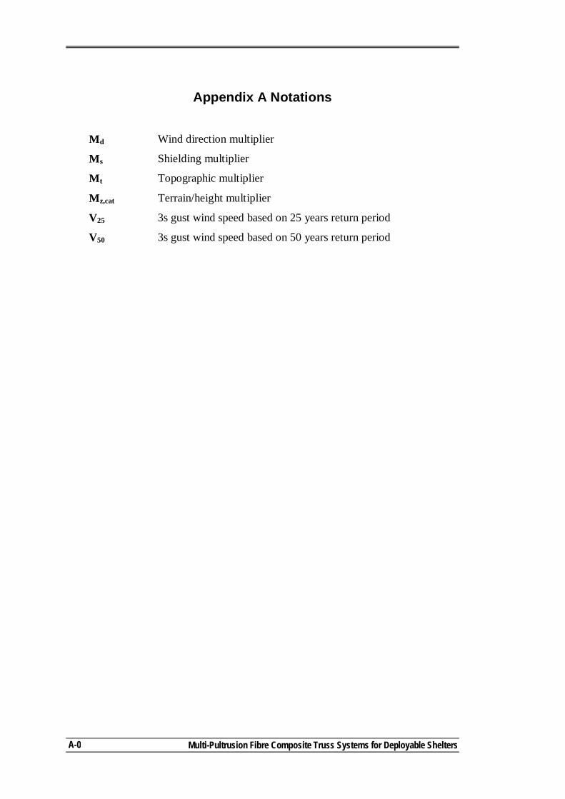
Multi-Pultrusion Fibre Composite Truss Systems for Deployable Shelters
A-0
Appendix A Notations
Md Wind direction multiplier
Ms Shielding multiplier
Mt Topographic multiplier
Mz,cat Terrain/height multiplier
V25 3s gust wind speed based on 25 years return period
V50 3s gust wind speed based on 50 years return period
A.1 Introduction
Appendix A: Assessing Loads on Deployable Shelters
A-1
Appendix A: Assessing Loads on Deployable Shelters
A.1. INTRODUCTION
While various forms of deployable shelters are still under development (Chapter
2), the performance and design criteria for such structures are not clearly defined.
The major structural loads to be considered can be categorised as dead loads, live
loads, wind loads and snow loads. Depending on the cladding system, the dead loads
are expected to be 0.08kPa over the whole area of the roof, in addition to the frame’s
own weight. Live loads are assessed as per the requirements of the related loading
codes for curved roofs. They are usually associated with the tributary area of
structural elements under consideration. Assuming frames of 35m span and spaced
6m apart, live load is 0.25kPa (AS/NZS 1170.1, 2002) and 0.36kPa (ASCE 7-95,
1996). Snow loads can be considered of a nominal value of 1.0kPa. All of the above
mentioned loads can be assessed with little difficulty.
Assessing the wind loading criteria for deployable structures is a challenging
process that requires engineering judgement. Loading codes are mainly developed
for buildings (of fixed nature) and, whilst more recent codes included some
recommendations for deployable structures, none has specific recommendations for
deployable shelters. For the different building systems presented in Chapter 2, no
justification was found for the specified wind loading criteria. This might be related
to the fact that they are used for military applications only. However, the M2S2
shelter system can be used for both military and civil applications. Accordingly,
there was an early recognition of the need to establish a generic system to determine
the design loads for the shelter system. This system should be flexible enough to be
used with different international loading codes and a range of different loading
scenarios. An important factor that should be considered during this exercise is cost
effectiveness. Designing a deployable structure for the worst loading scenario that
can happen anywhere around the world would be very expensive and result in a
structure that is over-designed for most other locations.
A.1 Introduction
Multi-Pultrusion Fibre Composite Truss Systems for Deployable Shelters
A-2
Due to the lightness of the M2S2 structure, wind loads are the most critical
loading type that determines the design. In addition, it is the most disputable loading
type. In this appendix, a wind loading assessment approach is proposed for further
consideration. The differences between the loading codes, as located in the literature,
are presented, along with an approach to correlate them. For deployable shelters, a
wind loading scenario is presented, followed by an example of assessing the wind
pressures on frames of 35m span and spaced 6m apart, by applying these scenarios
with two different loading codes (AS/NZS 1170.1, 2002 and ASCE 7-95, 1996).
A.2. WIND DATA IN LOADING CODES
Clearly with the international move towards limit states design, this philosophy
should form the basis for describing the loading criteria. Holmes (2001) stated that
advanced wind loading standards contain the following:
- a specification of a basic (reference) wind speed;
- modification factors for the effect of height and terrain type and sometimes for change of terrain, wind direction, topography and shelter;
- shape factors for the different structural shapes; - some account of possible resonant dynamic effects of wind on flexible
structures. Basic wind speeds are specified differently in the loading codes. The European
pre-standard ENV 1991-2-4 (1997), ISO 4354 (1997) and the Japanese AIJ (1996)
based wind load calculation on 10minutes mean wind speed, British code BS6399-
Part 2 (1997) used mean hourly wind speed, American codes (ASCE 7-95, 1996) and
ASCE 7-98, 1998) along with the Australian/New Zealand code (AS/NZS 1170.2,
2002) used 3s gust wind speed while the American code (ASCE 7-93, 1993) used
fastest-mile-of-wind. The first step to consider was to correlate between the different
reference wind speeds.
Durst (1960) suggested a relationship between mean hourly, non-cyclonic, wind
speed and wind speeds averaged over different times (which was incorporated in the
ASCE 7-93 (1993) commentary Table C5). This data was then used by Batts et al
(1980) to obtain the fastest-mile-of-wind. Comparing 50 years peak gust wind speeds
A.2 Wind Data in Loading Codes
Appendix A: Assessing Loads on Deployable Shelters
A-3
from analysis and ASCE 7-93 (1993) based fastest-mile-of–wind, Peterka and Shahid
(1998) suggested an average factor of 1.20.
Based on updated information by Krayer and Marshall (1992) gust factors for
cyclonic winds are higher than that of non-cyclonic wind by about 10%. Peterka and
Shahid (1998) suggested using data published by Batts et al (1980) to obtain peak
gusts for cyclonic winds (from fastest-mile-of-wind data) by dividing them by
appropriate gust factors in Durst (1960) to obtain the effective hourly mean, then
multiplying by the Krayer-Marshall gust factor of 1.69 for cyclones.
Some codes provide guidance on directional wind speed for non-cyclonic wind.
This is not applicable in cyclone-prone regions as the maximum wind speed is likely
to occur in any direction (AS/NZS 1170.2-Supplementary 1, 2002). Loading
standards that deal with cyclonic winds introduced region speed factor to allow for
the uncertainties in the predicted design wind speeds. AS/NZS 1170.2 (2002)
specifies a factor of 1.05 and 1.10 for tropical cyclone regions C and D respectively.
In ASCE 7-93 (1993), a cyclone coast factor of 1.05 was implemented in the
importance factor. Peterka and Shahid (1998) noticed that non-cyclonic wind speeds
on the cyclonic coast are not significantly different from speeds at interior stations
with a typical range of 38m/s to 42.5m/s, for 50 years case, with decreasing speeds
on the western coast of the United States.
Tropical cyclones occur over tropical oceans. They rapidly degenerate when they
move over land or into cooler water and are usually at full strength between latitude
20 and 30 with the possibility of reaching latitude 10 (Holmes, 2001). Decay of
cyclones inland have been predicted by Batts et al (1980) (well beyond 200km) and
Vickery and Twisdale (1995a,b) (100km) for 50 years winds. In developing the wind
map for ASCE 7-95 (1996), Peterka and Shahid (1998) used a distance of 160km, as
specified in ASCE 7-93 (1993). AS/NZS 1170.2-AMDT No 1 (2005) specified 50km
in each change from cyclonic regions D to C to B (Figure 3.1-AS/NZS 1170.2,
2002).
A.3 Wind Loading on Deployable Shelters
Multi-Pultrusion Fibre Composite Truss Systems for Deployable Shelters
A-4
A.3. WIND LOADING ON DEPLOYABLE SHELTERS
A typical characteristic of shelter structures is that they generally have large
doors. Internal wind pressures can change significantly, in magnitude and in
direction, depending on the size and status of the door opening. Accordingly, the
decision to design for open-door or closed-door buildings will have a major effect on
the overall design. Little information was found in the literature to assist in this
decision making. In the case of M2S2 the situation is further complicated by the fact
that the structure might have no doors at all (i.e open at both sides).
The two major wind categories that are found in the international loading codes
are cyclonic wind and non-cyclonic wind. Designing the M2S2 structure to withstand
cyclonic wind and then using it in non-cyclonic regions has significant cost
consequences. Accordingly, the concept used in assessing the wind loads should
recognise the necessity of having a cost effective alternative that allows using the
structure in both cyclonic and non-cyclonic regions without major cost penalties.
In spite of not specifically being developed for deployable shelters, the Unified
Facilities Criteria (UFC) documents specify a few important parameters for
designing shelter systems. The UFC 4-211-01N (2004) specifies the borderline
between open-door and close-door load cases to be 27m/s. In cyclonic zones, the
UFC 3-310-01 (2005) specifies an importance factor for temporary structures of
0.77.
The shelter system is not flexible enough for dynamic wind effects to have a
major influence. In assessing shape factors, some differences were found in the
different international loading codes (Holmes, 2001). This can be attributed to the
fluctuation in the instantaneous wind pressures due to the nature of turbulent flow
over large roofs. However, for arched roofs, the maximum negative pressure
coefficients in the central part of the roof are quite similar in most international
loading codes (Holmes, 2001).
Most deployable shelters are expected to be placed in open terrain. Accordingly,
a standard category (water surfaces, open terrain, grassland with few well scattered
obstructions) seems reasonable for the shelter ultimate limit state (ULS) design. In
assessing wind loads in this project, non-directional wind speed was considered. This
A.3 Wind Loading on Deployable Shelters
Appendix A: Assessing Loads on Deployable Shelters
A-5
is a conservative approach but, it provides consistency with the different loading
codes. Other special factors, such as topography and shelter factors, are not
considered due to their local nature.
As shown in Sec. A.2, loading codes have different approaches in assessing the
basic wind speed. However, all codes assess the basic wind speed/pressure based on
the estimated design life of the structure and its intended use.
The ROC (MCCDC, 1990) specified a minimum design life of 15 years for
deployable shelters (Chapter 2). AS/NZS 1170.2 (2002) states that the minimum
design working life1 for ultimate limit state (ULS) considerations of any structure
shall be 25 years2 (Sec 3.3 AS/NZS 1170.2-2002). The expected design life for
composite materials is about 25 years. It is a reasonable assumption to set the design
life of the M2S2 shelter system to 25 years.
M2S2 shelters can be used as shelters for military forces, civilian humanitarian
aid, natural disaster scenarios and as exhibition halls. When used without doors, the
shelter will be of temporary nature (eg exhibition halls). When doors are open, the
shelter will be in a temporary stage, until the doors are closed. In using the loading
codes, the shelter can be considered as a temporary structure in these two cases
(scenario 1). With doors closed, the shelter should be able to carry the maximum site
wind loads as a normal structure (scenario 2). This approach was also applied to non-
cyclonic regions.
In placing the shelter in a cyclonic region, the related wind loads should be
considered. Peterka and Shahid (1998) found that non-cyclonic wind speeds on the
cyclonic coasts of the United States are not significantly different from wind speeds
at interior stations. Accordingly, it was decided to design the M2S2 shelter for the
maximum wind speed of the non-cyclonic region directly adjacent to the cyclonic
region for scenarios 1 and 2. Cyclonic wind speeds/factors are applied to the
structure with doors assumed closed (scenario 3 with cyclone kit installed).
More recent loading codes (like AS/NZS 1170.2 - 2002) combine the design life
of the structure and the importance level to assess the annual probability of 1 The time where the structure is extended and subject to wind, AS/NZS1170-2 2002. 2 For New Zealand
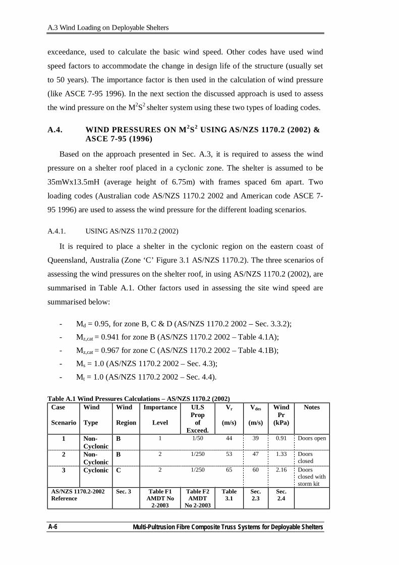
A.3 Wind Loading on Deployable Shelters
Multi-Pultrusion Fibre Composite Truss Systems for Deployable Shelters
A-6
exceedance, used to calculate the basic wind speed. Other codes have used wind
speed factors to accommodate the change in design life of the structure (usually set
to 50 years). The importance factor is then used in the calculation of wind pressure
(like ASCE 7-95 1996). In the next section the discussed approach is used to assess
the wind pressure on the M2S2 shelter system using these two types of loading codes.
A.4. WIND PRESSURES ON M2S2 USING AS/NZS 1170.2 (2002) & ASCE 7-95 (1996)
Based on the approach presented in Sec. A.3, it is required to assess the wind
pressure on a shelter roof placed in a cyclonic zone. The shelter is assumed to be
35mWx13.5mH (average height of 6.75m) with frames spaced 6m apart. Two
loading codes (Australian code AS/NZS 1170.2 2002 and American code ASCE 7-
95 1996) are used to assess the wind pressure for the different loading scenarios.
A.4.1. USING AS/NZS 1170.2 (2002)
It is required to place a shelter in the cyclonic region on the eastern coast of
Queensland, Australia (Zone ‘C’ Figure 3.1 AS/NZS 1170.2). The three scenarios of
assessing the wind pressures on the shelter roof, in using AS/NZS 1170.2 (2002), are
summarised in Table A.1. Other factors used in assessing the site wind speed are
summarised below:
- Md = 0.95, for zone B, C & D (AS/NZS 1170.2 2002 – Sec. 3.3.2); - Mz,cat = 0.941 for zone B (AS/NZS 1170.2 2002 – Table 4.1A);
- Mz,cat = 0.967 for zone C (AS/NZS 1170.2 2002 – Table 4.1B); - Ms = 1.0 (AS/NZS 1170.2 2002 – Sec. 4.3);
- Mt = 1.0 (AS/NZS 1170.2 2002 – Sec. 4.4). Table A.1 Wind Pressures Calculations – AS/NZS 1170.2 (2002)
Case Wind Wind Importance ULS Prop
Vr Vdes Wind Pr
Notes
Scenario Type Region Level of Exceed.
(m/s) (m/s) (kPa)
1 Non-Cyclonic
B 1 1/50 44 39 0.91 Doors open
2 Non-Cyclonic
B 2 1/250 53 47 1.33 Doors closed
3 Cyclonic C 2 1/250 65 60 2.16 Doors closed with storm kit
AS/NZS 1170.2-2002 Reference
Sec. 3 Table F1 AMDT No
2-2003
Table F2 AMDT
No 2-2003
Table 3.1
Sec. 2.3
Sec. 2.4
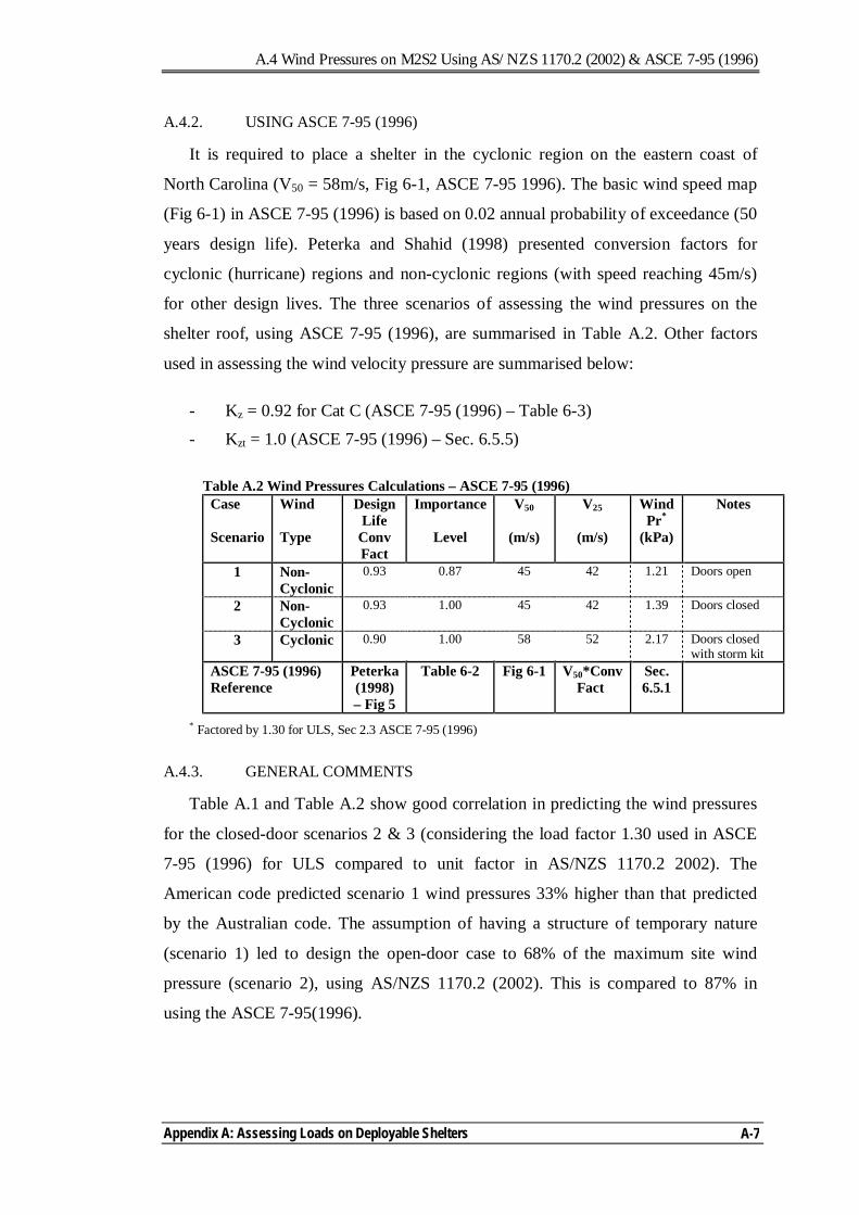
A.4 Wind Pressures on M2S2 Using AS/NZS 1170.2 (2002) & ASCE 7-95 (1996)
Appendix A: Assessing Loads on Deployable Shelters
A-7
A.4.2. USING ASCE 7-95 (1996)
It is required to place a shelter in the cyclonic region on the eastern coast of
North Carolina (V50 = 58m/s, Fig 6-1, ASCE 7-95 1996). The basic wind speed map
(Fig 6-1) in ASCE 7-95 (1996) is based on 0.02 annual probability of exceedance (50
years design life). Peterka and Shahid (1998) presented conversion factors for
cyclonic (hurricane) regions and non-cyclonic regions (with speed reaching 45m/s)
for other design lives. The three scenarios of assessing the wind pressures on the
shelter roof, using ASCE 7-95 (1996), are summarised in Table A.2. Other factors
used in assessing the wind velocity pressure are summarised below:
- Kz = 0.92 for Cat C (ASCE 7-95 (1996) – Table 6-3) - Kzt = 1.0 (ASCE 7-95 (1996) – Sec. 6.5.5)
Table A.2 Wind Pressures Calculations – ASCE 7-95 (1996)
Case Wind Design Life
Importance V50 V25 Wind Pr*
Notes
Scenario Type Conv Fact
Level (m/s) (m/s) (kPa)
1 Non-Cyclonic
0.93 0.87 45 42 1.21 Doors open
2 Non-Cyclonic
0.93 1.00 45 42 1.39 Doors closed
3 Cyclonic 0.90 1.00 58 52 2.17 Doors closed with storm kit
ASCE 7-95 (1996) Reference
Peterka (1998) – Fig 5
Table 6-2 Fig 6-1 V50*Conv Fact
Sec. 6.5.1
* Factored by 1.30 for ULS, Sec 2.3 ASCE 7-95 (1996)
A.4.3. GENERAL COMMENTS
Table A.1 and Table A.2 show good correlation in predicting the wind pressures
for the closed-door scenarios 2 & 3 (considering the load factor 1.30 used in ASCE
7-95 (1996) for ULS compared to unit factor in AS/NZS 1170.2 2002). The
American code predicted scenario 1 wind pressures 33% higher than that predicted
by the Australian code. The assumption of having a structure of temporary nature
(scenario 1) led to design the open-door case to 68% of the maximum site wind
pressure (scenario 2), using AS/NZS 1170.2 (2002). This is compared to 87% in
using the ASCE 7-95(1996).
A.5 References
Multi-Pultrusion Fibre Composite Truss Systems for Deployable Shelters
A-8
A.5. REFERENCES
American Society of Civil Engineers. (1993). Minimum design loads for buildings and other structures. ANSI/ASCE 7-93, ASCE, Reston, Va.
American Society of Civil Engineers. (1996). Minimum design loads for buildings and other structures. ANSI/ASCE 7-95, ASCE, New York.
American Society of Civil Engineers. (1998). Minimum design loads for buildings and other structures. ANSI/ASCE 7-98, ASCE, New York.
Architectural Institute of Japan. (1996). AIJ recommendations for loads on buildings. AIJ, Tokyo.
Batts, M. E., Cordes, M. R., Russell, L. R., Shaver, J. R., and Simiu, E. (1980). Hurricane wind speeds in the United States. Washington, D.C.
British Standards Institute. (1997). Basis of design and actions on structures - wind loads. DD ENV 1991-2-4, BSI, London.
British Standards Institute. (1997). Loading for buildings - Part 2. Code of practice for wind loads. BS6399: Part 2: 1997.
Carradine, D. M., and Plaut, R. H. (1998). Arch supported membrane shelters under wind and snow loading. International Journal of Space Structures, 13(4), 197-202.
Department of Defence. (1996). Loads. Military Handbook 1002/2A. USA. Department of Defence. (2004). Design: aircraft maintenance hangers: type I and
type II. UFC 4-211-01N. USA. Department of Defence. (2005). Structural load data. UFC 3-310-01. USA.
Durst, C. S. (1960). Wind speeds over short periods of time. Meteorological Magazine, 89, 181-186.
Holmes, J. D. (2001). Wind loading on structures, Spon Press, London. International Standards Organisation. (1997). Wind actions on structures. ISO 4354.
Krayer, W. R., and Marshall, W. R. (1992). Gust factors applied to hurricane winds. Bulletin of the American Meteorological Society, 73, 613-617.
MCCDC. (1990). Required operational capability (ROC) for a marine corps expeditionary aircraft maintenance shelter. LOG 33.1A, Virginia.
Peterka, J. A., and Shahid, S. (1998). Design gust wind speeds in the United States. Journal of Structural Engineering, 124(2), 207-214.
Standards Australia. (2002a). AS/NZS 1170.0:2002 Structural design actions - General principles. Sydney.
Standards Australia. (2002b). AS/NZS 1170.1:2002 Structural design actions - Part 1: Permanent, imposed and other actions. Sydney.
Standards Australia. (2002c). AS/NZS 1170.2:2002 Structural design actions - Wind actions. Sydney.
Strarch. (1991). Analysis of US military requirements for large deployable shelters. Sydney.
A.5 References
Appendix A: Assessing Loads on Deployable Shelters
A-9
Strarch. (2004). The Starch modular military shelter system - Load specification. Sydney.
Vickery, P. J., and Twisdale, L. A. (1995a). Prediction of hurricane wind speed in the United States. Journal of Structural Division, 121(11), 1691-1699.
Vickery, P. J., and Twisdale, L. A. (1995b). Windfield and filling models for hurricane wind speed predictions. Journal of Structural Division, 121(11), 1700-1709.

Multi-Pultrusion Fibre Composite Truss Systems for Deployable Shelters
A-10
B.1 Introduction
Appendix B: M2S2 Analysis Procedures
B-1
Appendix B: M2S2 Analysis Procedures
B.1. INTRODUCTION
The Military Modular Shelter System (M2S2) initiative is a research project that
aims to develop a fibre composite re-deployable arched shelter system with rigid
PVC or fabric cladding. The main frames are formed from modular fibre composite
panels that are connected and stressed in position by prestressing cables. Using
prestressing as a deploying mechanism, applying loads at the erection and assembly
stages and changing of the support boundary conditions necessitates the inclusion of
the erection process in the frame analysis. This appendix presents a brief description
of the three analysis procedures, two linear and one non-linear, used to predict the
frame member. The analyses comparison shows that modelling the erection process
along with applying loads relevant to each deploying stage, by nonlinear analysis, is
essential for this type of structure.
B.2. STRUCTURAL ANALYSIS OF M2S2 SHELTER FRAMES
B.2.1. MODEL DEVELOPMENT
Prior to conducting detailed investigations of the M2S2 shelter system, it was
important to establish modelling procedures to assess the stress levels in the different
components. As presented in Chapter 1, both the boundary conditions and the
applied loads change from the erection stage to the deployed stage. The support
(boundary) conditions change from sliding during the erection stage to hinge in the
deployed stage. The structure’s own weight, roofing and services dead loads are
carried by the frames while on the ground, prior to carrying any prestressing.
Reaching the final deployed position, the prestressing cables are blocked and the
moving supports are fixed. Other loads are then applied on the deployed (stressed)
structure.
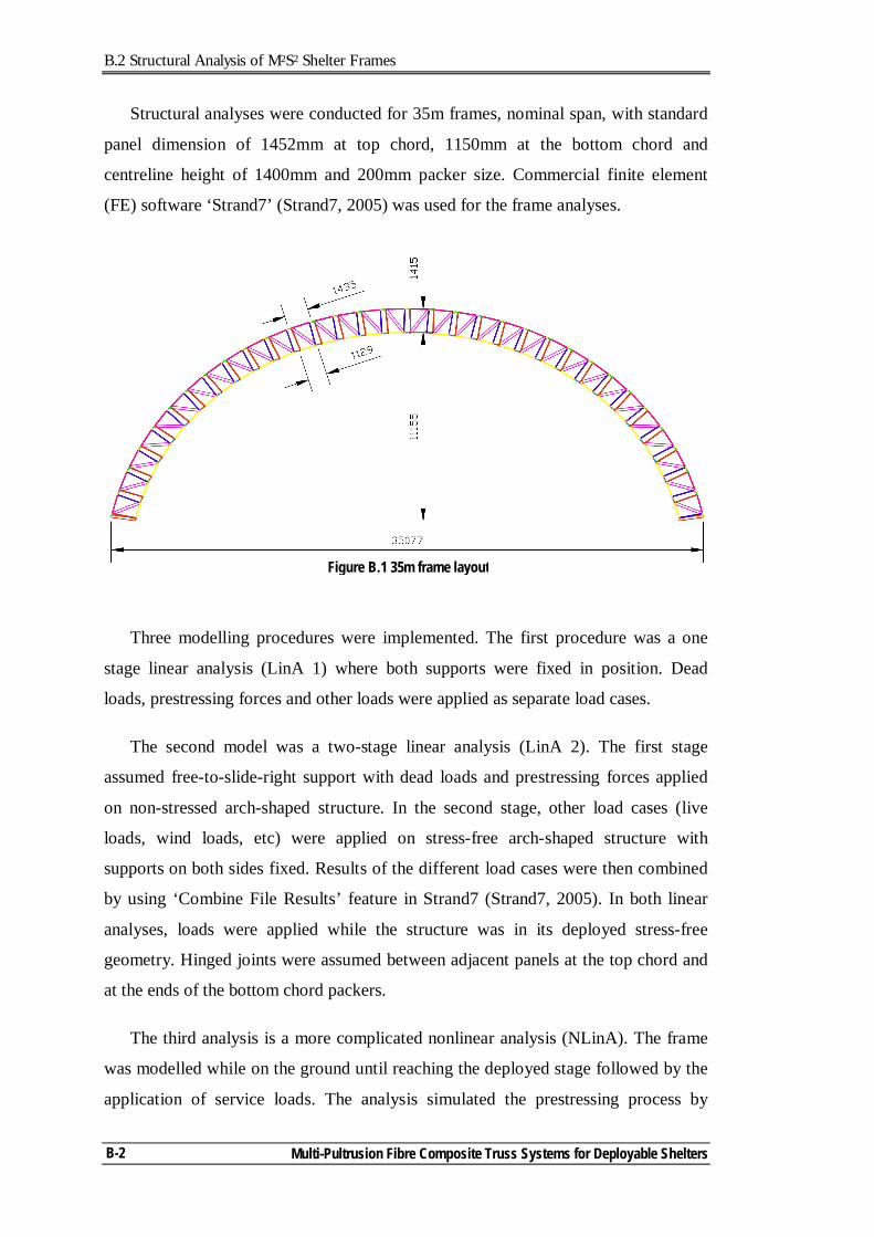
B.2 Structural Analysis of M2S2 Shelter Frames
Multi-Pultrusion Fibre Composite Truss Systems for Deployable Shelters
B-2
Structural analyses were conducted for 35m frames, nominal span, with standard
panel dimension of 1452mm at top chord, 1150mm at the bottom chord and
centreline height of 1400mm and 200mm packer size. Commercial finite element
(FE) software ‘Strand7’ (Strand7, 2005) was used for the frame analyses.
Three modelling procedures were implemented. The first procedure was a one
stage linear analysis (LinA 1) where both supports were fixed in position. Dead
loads, prestressing forces and other loads were applied as separate load cases.
The second model was a two-stage linear analysis (LinA 2). The first stage
assumed free-to-slide-right support with dead loads and prestressing forces applied
on non-stressed arch-shaped structure. In the second stage, other load cases (live
loads, wind loads, etc) were applied on stress-free arch-shaped structure with
supports on both sides fixed. Results of the different load cases were then combined
by using ‘Combine File Results’ feature in Strand7 (Strand7, 2005). In both linear
analyses, loads were applied while the structure was in its deployed stress-free
geometry. Hinged joints were assumed between adjacent panels at the top chord and
at the ends of the bottom chord packers.
The third analysis is a more complicated nonlinear analysis (NLinA). The frame
was modelled while on the ground until reaching the deployed stage followed by the
application of service loads. The analysis simulated the prestressing process by
Figure B.1 35m frame layout
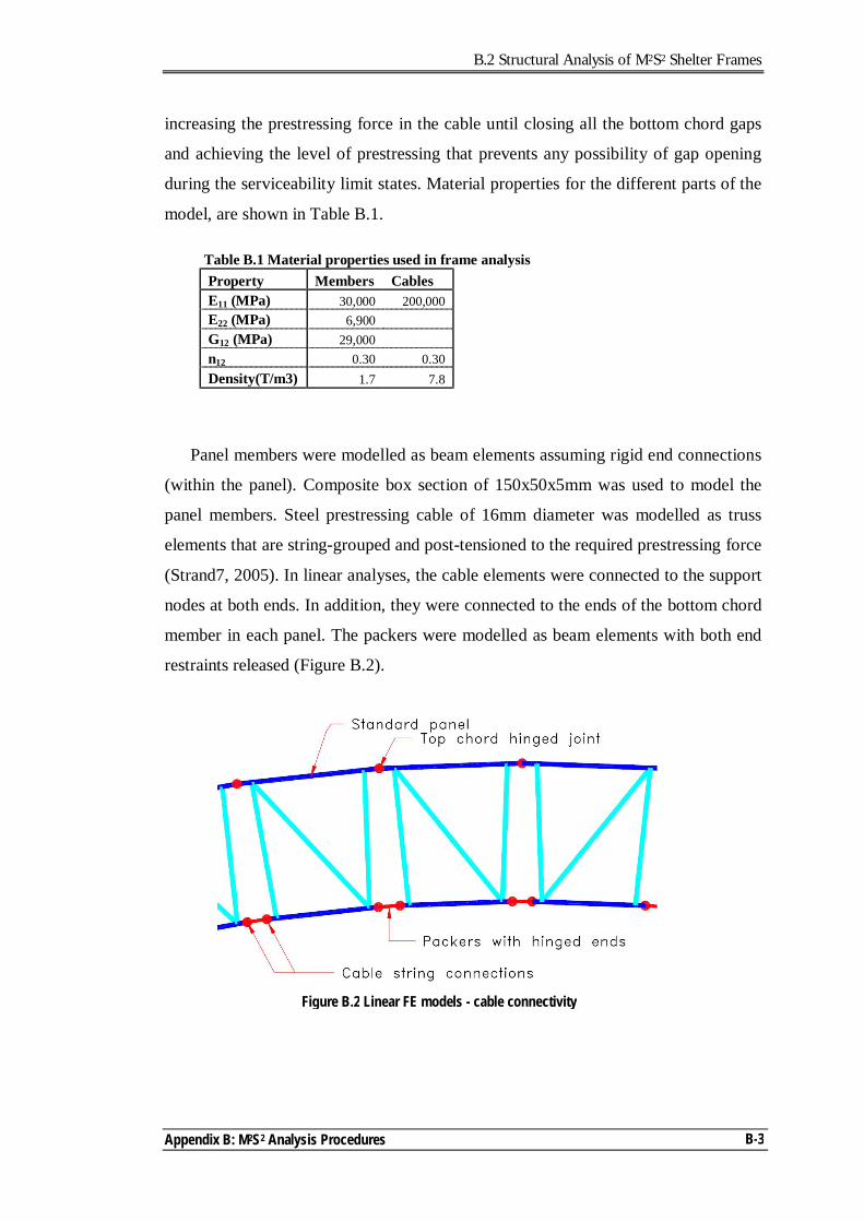
B.2 Structural Analysis of M2S2 Shelter Frames
Appendix B: M2S2 Analysis Procedures
B-3
increasing the prestressing force in the cable until closing all the bottom chord gaps
and achieving the level of prestressing that prevents any possibility of gap opening
during the serviceability limit states. Material properties for the different parts of the
model, are shown in Table B.1.
Table B.1 Material properties used in frame analysis Property Members Cables E11 (MPa) 30,000 200,000 E22 (MPa) 6,900 G12 (MPa) 29,000 ν12 0.30 0.30 Density(T/m3) 1.7 7.8
Panel members were modelled as beam elements assuming rigid end connections
(within the panel). Composite box section of 150x50x5mm was used to model the
panel members. Steel prestressing cable of 16mm diameter was modelled as truss
elements that are string-grouped and post-tensioned to the required prestressing force
(Strand7, 2005). In linear analyses, the cable elements were connected to the support
nodes at both ends. In addition, they were connected to the ends of the bottom chord
member in each panel. The packers were modelled as beam elements with both end
restraints released (Figure B.2).
Figure B.2 Linear FE models - cable connectivity
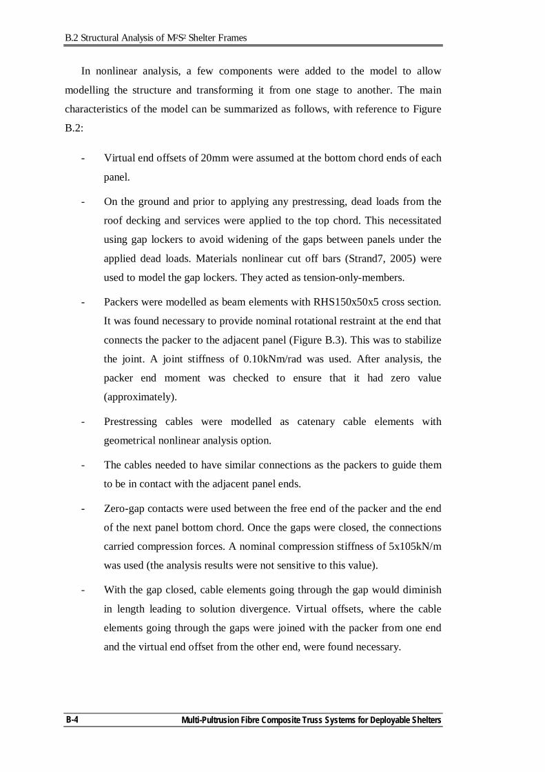
B.2 Structural Analysis of M2S2 Shelter Frames
Multi-Pultrusion Fibre Composite Truss Systems for Deployable Shelters
B-4
In nonlinear analysis, a few components were added to the model to allow
modelling the structure and transforming it from one stage to another. The main
characteristics of the model can be summarized as follows, with reference to Figure
B.2:
- Virtual end offsets of 20mm were assumed at the bottom chord ends of each
panel.
- On the ground and prior to applying any prestressing, dead loads from the
roof decking and services were applied to the top chord. This necessitated
using gap lockers to avoid widening of the gaps between panels under the
applied dead loads. Materials nonlinear cut off bars (Strand7, 2005) were
used to model the gap lockers. They acted as tension-only-members.
- Packers were modelled as beam elements with RHS150x50x5 cross section.
It was found necessary to provide nominal rotational restraint at the end that
connects the packer to the adjacent panel (Figure B.3). This was to stabilize
the joint. A joint stiffness of 0.10kNm/rad was used. After analysis, the
packer end moment was checked to ensure that it had zero value
(approximately).
- Prestressing cables were modelled as catenary cable elements with
geometrical nonlinear analysis option.
- The cables needed to have similar connections as the packers to guide them
to be in contact with the adjacent panel ends.
- Zero-gap contacts were used between the free end of the packer and the end
of the next panel bottom chord. Once the gaps were closed, the connections
carried compression forces. A nominal compression stiffness of 5x10⁵kN/m
was used (the analysis results were not sensitive to this value).
- With the gap closed, cable elements going through the gap would diminish
in length leading to solution divergence. Virtual offsets, where the cable
elements going through the gaps were joined with the packer from one end
and the virtual end offset from the other end, were found necessary.
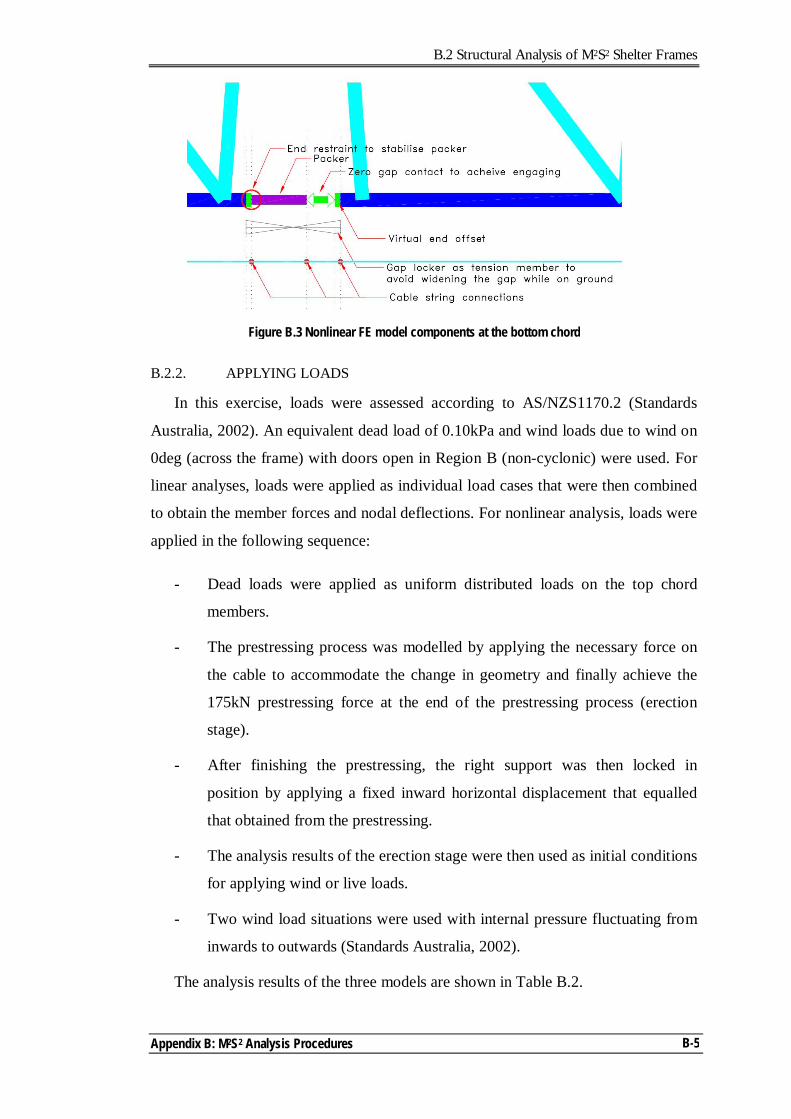
B.2 Structural Analysis of M2S2 Shelter Frames
Appendix B: M2S2 Analysis Procedures
B-5
B.2.2. APPLYING LOADS
In this exercise, loads were assessed according to AS/NZS1170.2 (Standards
Australia, 2002). An equivalent dead load of 0.10kPa and wind loads due to wind on
0deg (across the frame) with doors open in Region B (non-cyclonic) were used. For
linear analyses, loads were applied as individual load cases that were then combined
to obtain the member forces and nodal deflections. For nonlinear analysis, loads were
applied in the following sequence:
- Dead loads were applied as uniform distributed loads on the top chord
members.
- The prestressing process was modelled by applying the necessary force on
the cable to accommodate the change in geometry and finally achieve the
175kN prestressing force at the end of the prestressing process (erection
stage).
- After finishing the prestressing, the right support was then locked in
position by applying a fixed inward horizontal displacement that equalled
that obtained from the prestressing.
- The analysis results of the erection stage were then used as initial conditions
for applying wind or live loads.
- Two wind load situations were used with internal pressure fluctuating from
inwards to outwards (Standards Australia, 2002).
The analysis results of the three models are shown in Table B.2.
Figure B.3 Nonlinear FE model components at the bottom chord
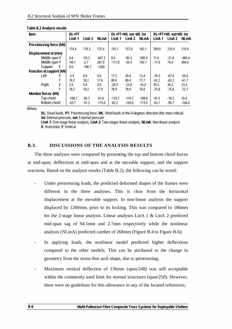
B.2 Structural Analysis of M2S2 Shelter Frames
Multi-Pultrusion Fibre Composite Truss Systems for Deployable Shelters
B-6
B.3. DISCUSSIONS OF THE ANALYSIS RESULTS
The three analyses were compared by presenting the top and bottom chord forces
at mid-span, deflections at mid-span and at the movable support, and the support
reactions. Based on the analysis results (Table B.2), the following can be noted:
- Under prestressing loads, the predicted deformed shapes of the frames were
different in the three analyses. This is clear from the horizontal
displacement at the movable support. In non-linear analysis the support
displaced by 1260mm, prior to its locking. This was compared to 186mm
for the 2-stage linear analysis. Linear analyses LinA 1 & LinA 2 predicted
mid-span sag of 94.1mm and 2.7mm respectively while the nonlinear
analysis (NLinA) predicted camber of 268mm (Figure B.4 to Figure B.6);
- In applying loads, the nonlinear model predicted higher deflections
compared to the other models. This can be attributed to the change in
geometry from the stress-free arch shape, due to prestressing;
- Maximum vertical deflection of 136mm (span/248) was still acceptable
within the commonly used limit for normal structures (span/250). However,
there were no guidelines for this allowance in any of the located references;
Table B.2 Analysis results ___________________________________________________________________________________________ Item DL+PT DL+PT+WL ext -WL int DL+PT+WL ext+WL int LinA 1 LinA 2 NLinA LinA 1 LinA 2 NLinA LinA 1 LinA 2 NLinA ___________________________________________________________________________________________ Pre-stressing force (kN) 174.4 176.3 175.6 155.1 157.0 165.1 209.0 210.9 210.9 Displacement at (mm) Middle span X 0.0 -93.3 -607.3 8.0 -85.3 -585.9 71.6 -21.8 -485.4 Middle span Y -94.1 -2.7 267.9 -111.8 -20.4 192.7 -17.0 74.4 404.6 Support X 0.0 -186.7 -1260 Reaction at support (kN) Left X -2.9 0.0 0.0 17.5 20.4 12.4 -70.3 -67.4 -55.6 Y 18.2 18.2 17.6 80.4 80.4 77.7 -62.2 -62.2 -61.7 Right X 2.9 0.0 0.0 -20.9 -23.8 -16.0 39.3 36.3 23.4 Y 18.2 18.2 17.9 78.9 78.9 76.8 -75.8 -75.8 -72.7 Member forces (kN) Top chord -108.7 -85.7 -61.0 -133.7 -110.7 -108.8 -41.5 -18.5 35.6 Bottom chord -63.7 -91.3 -115.0 -82.2 -109.8 -113.0 -63.1 -90.7 -166.0 ____________________________________________________________________________________________ Where, DL: Dead loads, PT: Prestressing force, WL: Wind loads in the 0-degrees direction (the most critical) int: Internal pressure, ext: External pressure LinA 1: One-stage linear analysis, LinA 2: Two-stages linear analysis, NLinA: Non-linear analysis X: Horizontal, Y: Vertical
B.3 Discussions of the Analysis Results
Appendix B: M2S2 Analysis Procedures
B-7
- All models predicted similar vertical reactions. However, the non-linear
model predicted smaller horizontal reactions. This was attributed to the
increase in subtended angle (during the stressing process) with less
horizontal force component;
- Member force predictions were quite different in all analyses. One of the
serviceability limit state (SLS) criteria in designing this type of structures is
to have the bottom chord in compression under all load combinations. It is
apparent that the distribution of forces between the chords and the level of
these forces will influence this limit state. For example, in DL+PT+WL
ext+WL int, the reported chord forces in single stage linear analysis are (-
41kN top & -63kN bottom) while for 2-stage linear analysis are (-18kN top
& -90kN bottom). In non-linear analysis the chord forces are (+35kN top &
-166kN bottom). This implication has significant effect on assessing the
level of prestressing and accordingly the different frame behaviours that are
affected by the prestressing level.
Based on the comparison conducted above, it is clear that the analysis technique
does affect the prediction of force distributions in the frame, support reactions and
frame deflections. Linear analyses are not suitable for this type of structure.
Nonlinear analysis is required, where both the assembly stage and the erection stage
are included. However, it is important to verify the analysis results by testing frames
under applied loads. Friction effects could be another factor to be included in the
model.
Figure B.4 Deflected shape of the frame predicted by LinA 1
Deformed shape
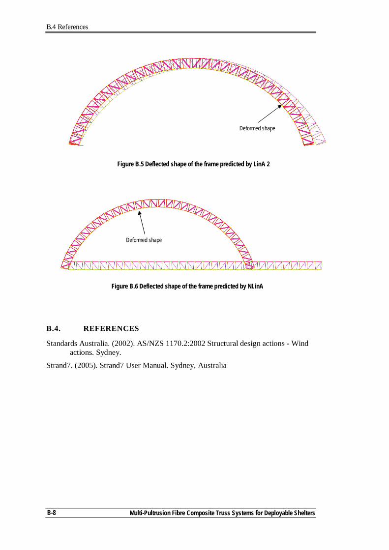
B.4 References
Multi-Pultrusion Fibre Composite Truss Systems for Deployable Shelters
B-8
B.4. REFERENCES
Standards Australia. (2002). AS/NZS 1170.2:2002 Structural design actions - Wind actions. Sydney.
Strand7. (2005). Strand7 User Manual. Sydney, Australia
Figure B.5 Deflected shape of the frame predicted by LinA 2
Deformed shape
Figure B.6 Deflected shape of the frame predicted by NLinA
Deformed shape
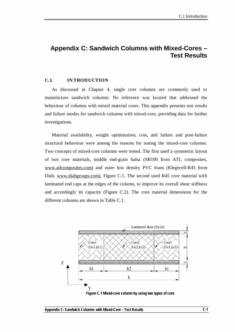
C.1 Introduction
Appendix C: Sandwich Columns with Mixed-Core – Test Results
C-1
Appendix C: Sandwich Columns with Mixed-Cores –
Test Results
C.1. INTRODUCTION
As discussed in Chapter 4, single core columns are commonly used to
manufacture sandwich columns. No reference was located that addressed the
behaviour of columns with mixed material cores. This appendix presents test results
and failure modes for sandwich columns with mixed-core, providing data for further
investigations.
Material availability, weight optimisation, cost, and failure and post-failure
structural behaviour were among the reasons for testing the mixed-core columns.
Two concepts of mixed-core columns were tested. The first used a symmetric layout
of two core materials, middle end-grain balsa (SB100 from ATL composites,
www.atlcomposites.com) and outer low density PVC foam (Klegecell-R45 from
Diab, www.diabgroups.com), Figure C.1. The second used R45 core material with
laminated end caps at the edges of the column, to improve its overall shear stiffness
and accordingly its capacity (Figure C.2). The core material dimensions for the
different columns are shown in Table C.1.
Figure C.1 Mixed-core column by using two types of core
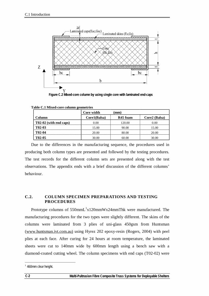
C.1 Introduction
Multi-Pultrusion Fibre Composite Truss Systems for Deployable Shelters
C-2
Table C.1 Mixed-core column geometries Core width (mm) Column Core1(Balsa) R45 foam Core2 (Balsa) T02-02 (with end caps) 0.00 120.00 0.00 T02-03 15.00 90.00 15.00 T02-04 20.00 80.00 20.00 T02-05 30.00 60.00 30.00
Due to the differences in the manufacturing sequence, the procedures used in
producing both column types are presented and followed by the testing procedures.
The test records for the different column sets are presented along with the test
observations. The appendix ends with a brief discussion of the different columns’
behaviour.
C.2. COLUMN SPECIMEN PREPARATIONS AND TESTING PROCEDURES
Prototype columns of 550mmL1x120mmWx24mmThk were manufactured. The
manufacturing procedures for the two types were slightly different. The skins of the
columns were laminated from 3 plies of uni-glass 450gsm from Huntsman
(www.huntsman.ivt.com.au) using Hyrez 202 epoxy-resin (Rogers, 2004) with peel
plies at each face. After curing for 24 hours at room temperature, the laminated
sheets were cut to 140mm wide by 600mm length using a bench saw with a
diamond-coated cutting wheel. The column specimens with end caps (T02-02) were
1 460mm clear height.
Figure C.2 Mixed-core column by using single core with laminated end-caps
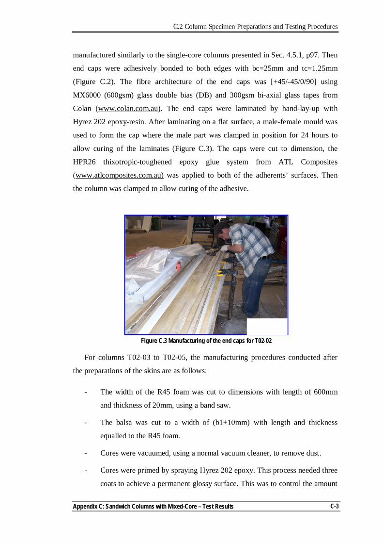
C.2 Column Specimen Preparations and Testing Procedures
Appendix C: Sandwich Columns with Mixed-Core – Test Results
C-3
manufactured similarly to the single-core columns presented in Sec. 4.5.1, p97. Then
end caps were adhesively bonded to both edges with bc=25mm and tc=1.25mm
(Figure C.2). The fibre architecture of the end caps was [+45/-45/0/90] using
MX6000 (600gsm) glass double bias (DB) and 300gsm bi-axial glass tapes from
Colan (www.colan.com.au). The end caps were laminated by hand-lay-up with
Hyrez 202 epoxy-resin. After laminating on a flat surface, a male-female mould was
used to form the cap where the male part was clamped in position for 24 hours to
allow curing of the laminates (Figure C.3). The caps were cut to dimension, the
HPR26 thixotropic-toughened epoxy glue system from ATL Composites
(www.atlcomposites.com.au) was applied to both of the adherents’ surfaces. Then
the column was clamped to allow curing of the adhesive.
For columns T02-03 to T02-05, the manufacturing procedures conducted after
the preparations of the skins are as follows:
- The width of the R45 foam was cut to dimensions with length of 600mm
and thickness of 20mm, using a band saw.
- The balsa was cut to a width of (b1+10mm) with length and thickness
equalled to the R45 foam.
- Cores were vacuumed, using a normal vacuum cleaner, to remove dust.
- Cores were primed by spraying Hyrez 202 epoxy. This process needed three
coats to achieve a permanent glossy surface. This was to control the amount
Figure C.3 Manufacturing of the end caps for T02-02
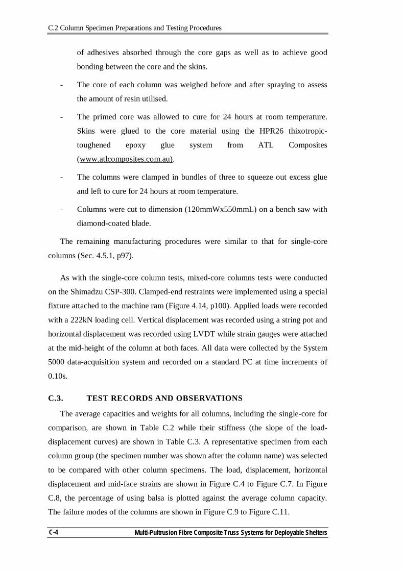
C.2 Column Specimen Preparations and Testing Procedures
Multi-Pultrusion Fibre Composite Truss Systems for Deployable Shelters
C-4
of adhesives absorbed through the core gaps as well as to achieve good
bonding between the core and the skins.
- The core of each column was weighed before and after spraying to assess
the amount of resin utilised.
- The primed core was allowed to cure for 24 hours at room temperature.
Skins were glued to the core material using the HPR26 thixotropic-
toughened epoxy glue system from ATL Composites
(www.atlcomposites.com.au).
- The columns were clamped in bundles of three to squeeze out excess glue
and left to cure for 24 hours at room temperature.
- Columns were cut to dimension (120mmWx550mmL) on a bench saw with
diamond-coated blade.
The remaining manufacturing procedures were similar to that for single-core
columns (Sec. 4.5.1, p97).
As with the single-core column tests, mixed-core columns tests were conducted
on the Shimadzu CSP-300. Clamped-end restraints were implemented using a special
fixture attached to the machine ram (Figure 4.14, p100). Applied loads were recorded
with a 222kN loading cell. Vertical displacement was recorded using a string pot and
horizontal displacement was recorded using LVDT while strain gauges were attached
at the mid-height of the column at both faces. All data were collected by the System
5000 data-acquisition system and recorded on a standard PC at time increments of
0.10s.
C.3. TEST RECORDS AND OBSERVATIONS
The average capacities and weights for all columns, including the single-core for
comparison, are shown in Table C.2 while their stiffness (the slope of the load-
displacement curves) are shown in Table C.3. A representative specimen from each
column group (the specimen number was shown after the column name) was selected
to be compared with other column specimens. The load, displacement, horizontal
displacement and mid-face strains are shown in Figure C.4 to Figure C.7. In Figure
C.8, the percentage of using balsa is plotted against the average column capacity.
The failure modes of the columns are shown in Figure C.9 to Figure C.11.
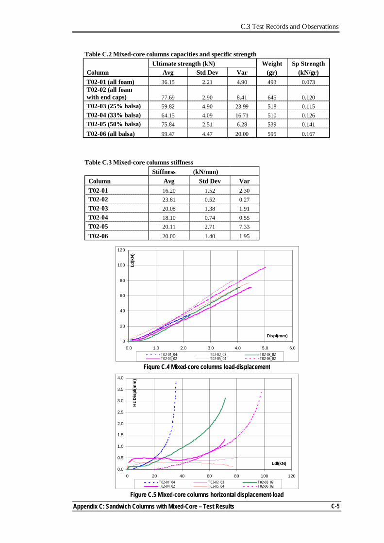
C.3 Test Records and Observations
Appendix C: Sandwich Columns with Mixed-Core – Test Results
C-5
Table C.2 Mixed-core columns capacities and specific strength Ultimate strength (kN) Weight Sp Strength Column Avg Std Dev Var (gr) (kN/gr) T02-01 (all foam) 36.15 2.21 4.90 493 0.073 T02-02 (all foam with end caps) 77.69 2.90 8.41 645 0.120 T02-03 (25% balsa) 59.82 4.90 23.99 518 0.115 T02-04 (33% balsa) 64.15 4.09 16.71 510 0.126 T02-05 (50% balsa) 75.84 2.51 6.28 539 0.141 T02-06 (all balsa) 99.47 4.47 20.00 595 0.167
Table C.3 Mixed-core columns stiffness Stiffness (kN/mm) Column Avg Std Dev Var T02-01 16.20 1.52 2.30 T02-02 23.81 0.52 0.27 T02-03 20.08 1.38 1.91 T02-04 18.10 0.74 0.55 T02-05 20.11 2.71 7.33 T02-06 20.00 1.40 1.95
Figure C.4 Mixed-core columns load-displacement
0
20
40
60
80
100
120
0.0 1.0 2.0 3.0 4.0 5.0 6.0
Displ(mm)
Ld(k
N)
T02-01_04 T02-02_03 T02-03_02T02-04_02 T02-05_04 T02-06_02
Figure C.5 Mixed-core columns horizontal displacement-load
0.0
0.5
1.0
1.5
2.0
2.5
3.0
3.5
4.0
0 20 40 60 80 100 120
Ldl(kN)
Hz
Dis
pl(m
m)
T02-01_04 T02-02_03 T02-03_02T02-04_02 T02-05_04 T02-06_02
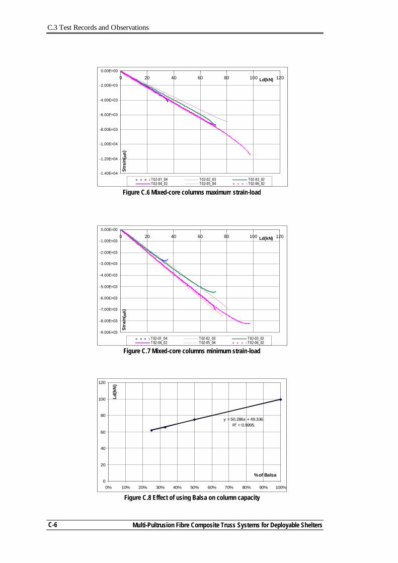
C.3 Test Records and Observations
Multi-Pultrusion Fibre Composite Truss Systems for Deployable Shelters
C-6
Figure C.6 Mixed-core columns maximum strain-load
-1.40E+04
-1.20E+04
-1.00E+04
-8.00E+03
-6.00E+03
-4.00E+03
-2.00E+03
0.00E+00
0 20 40 60 80 100 120Ld(kN)
Stra
in( µ
s)
T02-01_04 T02-02_03 T02-03_02T02-04_02 T02-05_04 T02-06_02
Figure C.7 Mixed-core columns minimum strain-load
-9.00E+03
-8.00E+03
-7.00E+03
-6.00E+03
-5.00E+03
-4.00E+03
-3.00E+03
-2.00E+03
-1.00E+03
0.00E+00
0 20 40 60 80 100 120Ld(kN)
Stra
in( µ
s)
T02-01_04 T02-02_03 T02-03_02T02-04_02 T02-05_04 T02-06_02
Figure C.8 Effect of using Balsa on column capacity
y = 50.286x + 49.336R2 = 0.9995
0
20
40
60
80
100
120
0% 10% 20% 30% 40% 50% 60% 70% 80% 90% 100%
% of Balsa
Ld(k
N)
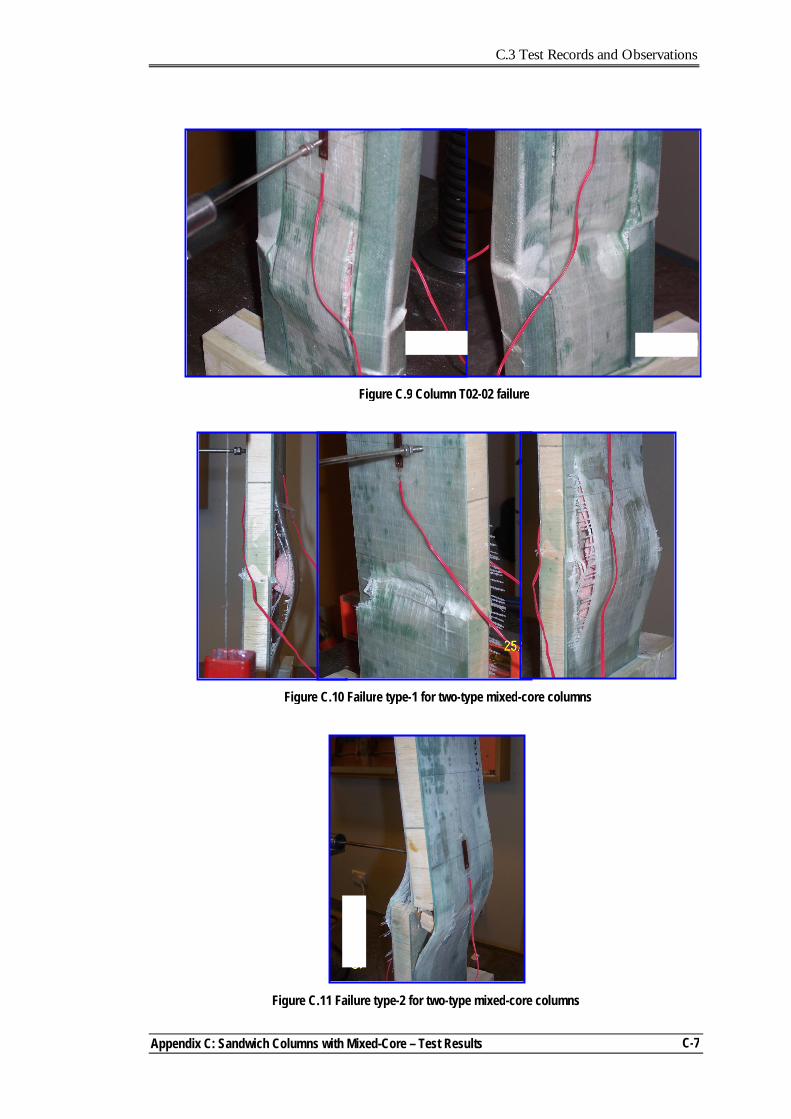
C.3 Test Records and Observations
Appendix C: Sandwich Columns with Mixed-Core – Test Results
C-7
Figure C.10 Failure type-1 for two-type mixed-core columns
Figure C.9 Column T02-02 failure
Figure C.11 Failure type-2 for two-type mixed-core columns
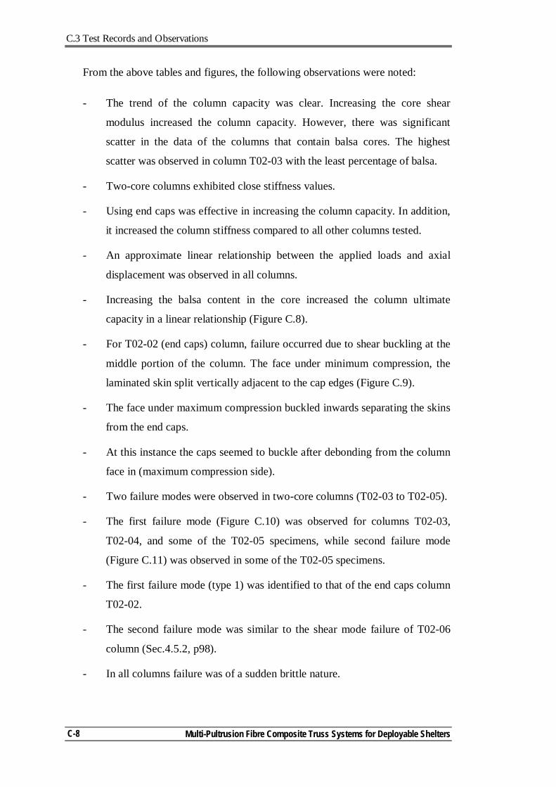
C.3 Test Records and Observations
Multi-Pultrusion Fibre Composite Truss Systems for Deployable Shelters
C-8
From the above tables and figures, the following observations were noted:
- The trend of the column capacity was clear. Increasing the core shear
modulus increased the column capacity. However, there was significant
scatter in the data of the columns that contain balsa cores. The highest
scatter was observed in column T02-03 with the least percentage of balsa.
- Two-core columns exhibited close stiffness values.
- Using end caps was effective in increasing the column capacity. In addition,
it increased the column stiffness compared to all other columns tested.
- An approximate linear relationship between the applied loads and axial
displacement was observed in all columns.
- Increasing the balsa content in the core increased the column ultimate
capacity in a linear relationship (Figure C.8).
- For T02-02 (end caps) column, failure occurred due to shear buckling at the
middle portion of the column. The face under minimum compression, the
laminated skin split vertically adjacent to the cap edges (Figure C.9).
- The face under maximum compression buckled inwards separating the skins
from the end caps.
- At this instance the caps seemed to buckle after debonding from the column
face in (maximum compression side).
- Two failure modes were observed in two-core columns (T02-03 to T02-05).
- The first failure mode (Figure C.10) was observed for columns T02-03,
T02-04, and some of the T02-05 specimens, while second failure mode
(Figure C.11) was observed in some of the T02-05 specimens.
- The first failure mode (type 1) was identified to that of the end caps column
T02-02.
- The second failure mode was similar to the shear mode failure of T02-06
column (Sec.4.5.2, p98).
- In all columns failure was of a sudden brittle nature.

C.4 Discussion of the Behaviour of the Mixed-Core Columns
Appendix C: Sandwich Columns with Mixed-Core – Test Results
C-9
C.4. DISCUSSION OF THE BEHAVIOUR OF THE MIXED-CORE COLUMNS
The discussion in this section raises points about the behaviour of mixed-core
columns and identifies considerations for future investigations.
- The weak core material was at the centre while the strong core material
(either balsa or end caps) were at the outside of the columns. Reversing the
the core layout, can it allow failure of the outer column edges (with weak
cores) and accordingly, provide a system to release energy in reaching the
ultimate capacity?
- The end caps increased the strength and stiffness of the column although
they contributed to heavier columns.
- The structure of the skins was uni-directional. For both types of mixed-core
columns, failure in the skins was observed along the line of the strong core.
Does this indicate that in modifying the fibre architecture we can have any
secondary behaviour that allows sustaining some of the column capacity
after reaching its ultimate capacity?
- The effect of the natural variation in the balsa became more pronounced in
columns with the least balsa content leading to more scatter in the column
behaviour.
- The linear relationship between the balsa content and the ultimate capacity
(Figure C.8) needs further investigation, because of the change of the failure
mode in the low-balsa and high-balsa content columns.
- The mixed-core concept requires further investigations using a more
consistent material (like PVC foam) to highlight this relationship.
- The skin strains at specified load level were smaller in T02-02 column
compared to other columns. This can be attributed to the contribution of the
end caps to the column carrying capacity.
- A FE model that can capture the behaviour of the mixed-core columns is
needed to achieve better understanding of the mechanism of their behaviour.
C.5 References
Multi-Pultrusion Fibre Composite Truss Systems for Deployable Shelters
C-10
C.5. REFERENCES
ATL Composites Homepage. www.atlcomposites.com.au.
Colan Homepage. www.colan.com.au. Diab Homepage. www.diabgroup.com.
Huntsman home page. www.huntsman.ivt.com.au. Rogers, D. (2004). Characterisation of Hyrez 201 laminating resin. Polymer Testing
Laboratory, University of Southern Queensland, Toowoomba, Queensland.
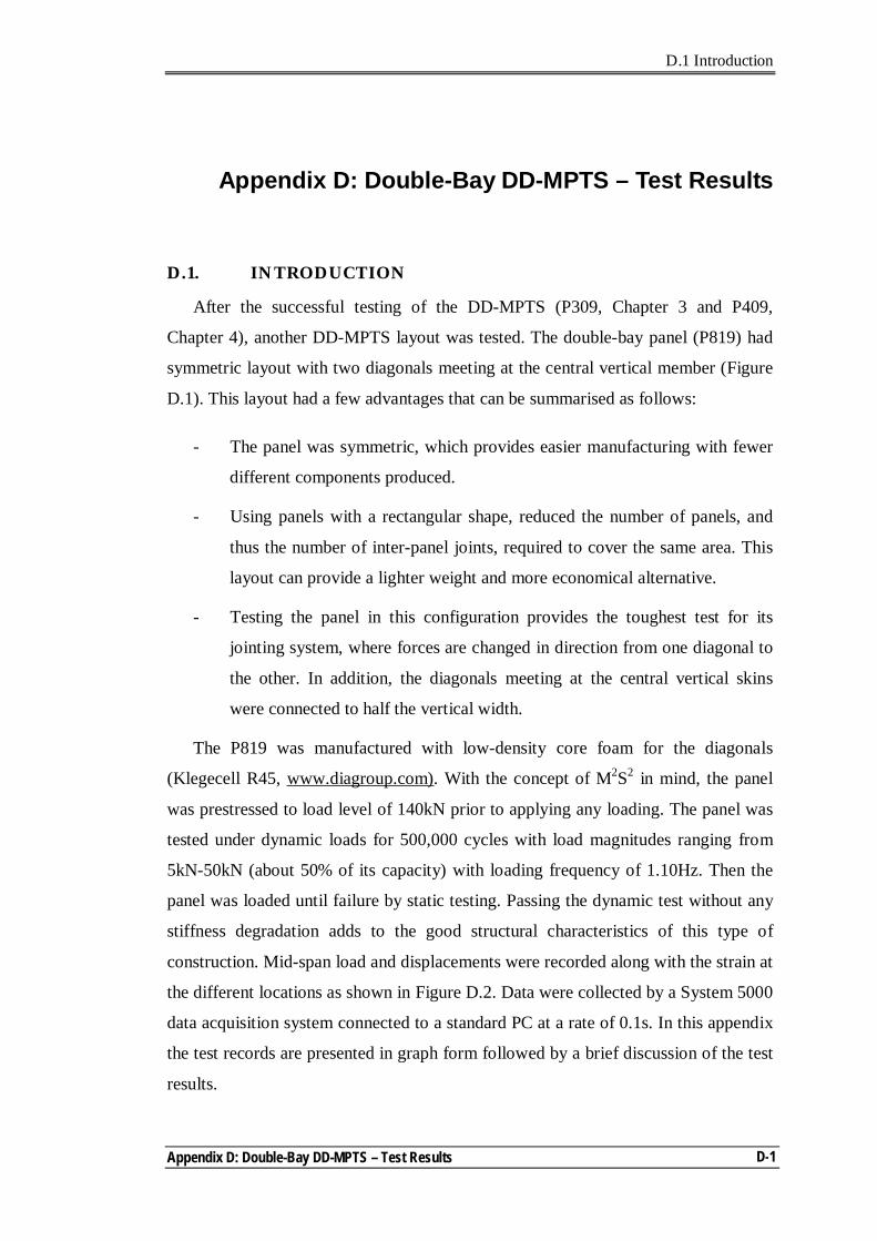
D.1 Introduction
Appendix D: Double-Bay DD-MPTS – Test Results
D-1
Appendix D: Double-Bay DD-MPTS – Test Results
D.1. INTRODUCTION
After the successful testing of the DD-MPTS (P309, Chapter 3 and P409,
Chapter 4), another DD-MPTS layout was tested. The double-bay panel (P819) had
symmetric layout with two diagonals meeting at the central vertical member (Figure
D.1). This layout had a few advantages that can be summarised as follows:
- The panel was symmetric, which provides easier manufacturing with fewer
different components produced.
- Using panels with a rectangular shape, reduced the number of panels, and
thus the number of inter-panel joints, required to cover the same area. This
layout can provide a lighter weight and more economical alternative.
- Testing the panel in this configuration provides the toughest test for its
jointing system, where forces are changed in direction from one diagonal to
the other. In addition, the diagonals meeting at the central vertical skins
were connected to half the vertical width.
The P819 was manufactured with low-density core foam for the diagonals
(Klegecell R45, www.diagroup.com). With the concept of M2S2 in mind, the panel
was prestressed to load level of 140kN prior to applying any loading. The panel was
tested under dynamic loads for 500,000 cycles with load magnitudes ranging from
5kN-50kN (about 50% of its capacity) with loading frequency of 1.10Hz. Then the
panel was loaded until failure by static testing. Passing the dynamic test without any
stiffness degradation adds to the good structural characteristics of this type of
construction. Mid-span load and displacements were recorded along with the strain at
the different locations as shown in Figure D.2. Data were collected by a System 5000
data acquisition system connected to a standard PC at a rate of 0.1s. In this appendix
the test records are presented in graph form followed by a brief discussion of the test
results.
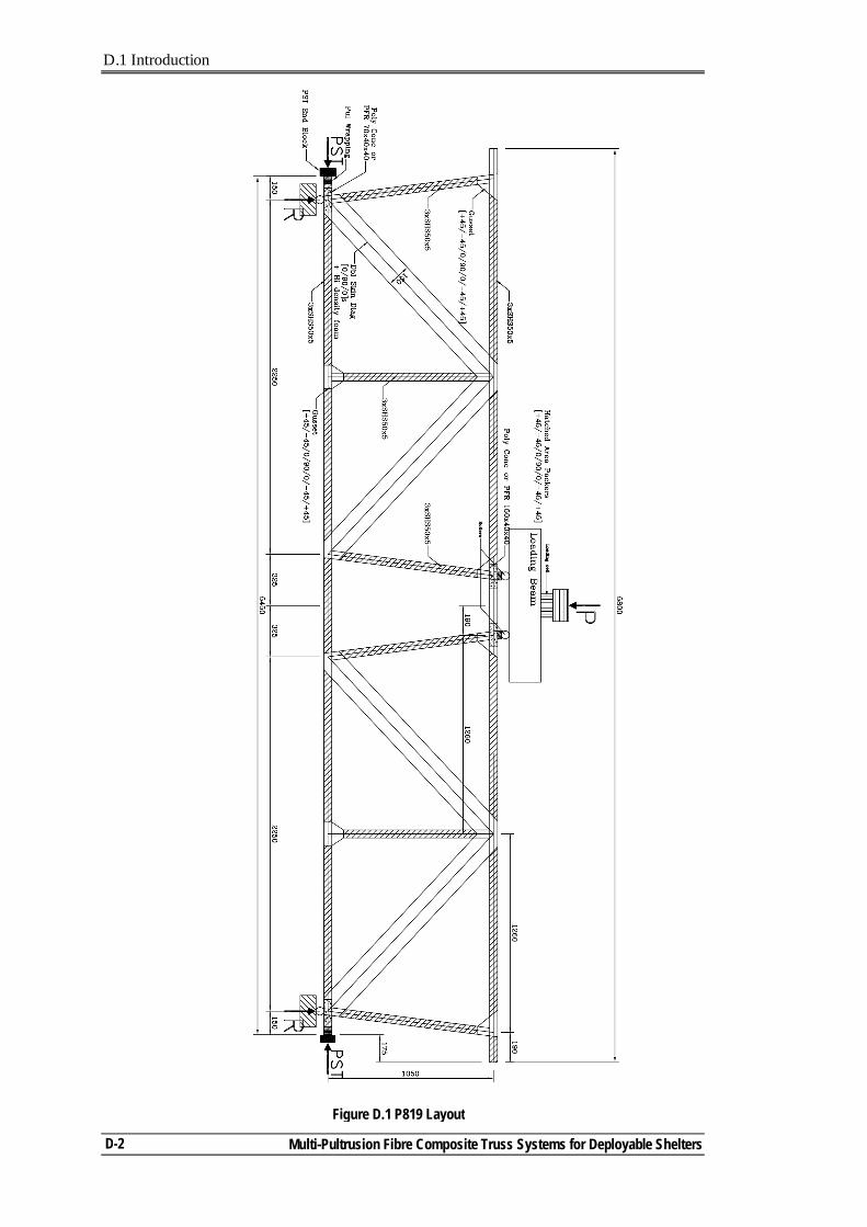
D.1 Introduction
Multi-Pultrusion Fibre Composite Truss Systems for Deployable Shelters
D-2
Figure D.1 P819 Layout
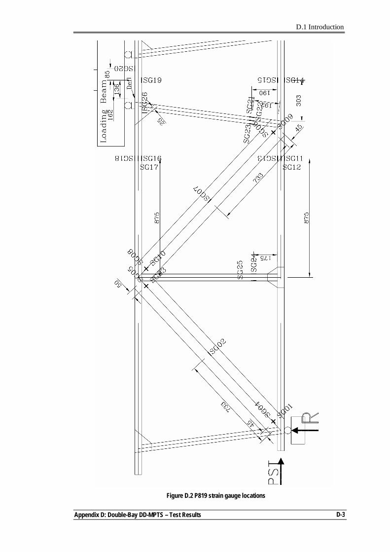
D.1 Introduction
Appendix D: Double-Bay DD-MPTS – Test Results
D-3
Figure D.2 P819 strain gauge locations
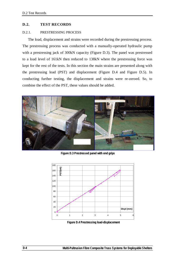
D.2 Test Records
Multi-Pultrusion Fibre Composite Truss Systems for Deployable Shelters
D-4
D.2. TEST RECORDS
D.2.1. PRESTRESSING PROCESS
The load, displacement and strains were recorded during the prestressing process.
The prestressing process was conducted with a manually-operated hydraulic pump
with a prestressing jack of 300kN capacity (Figure D.3). The panel was prestressed
to a load level of 161kN then reduced to 138kN where the prestressing force was
kept for the rest of the tests. In this section the main strains are presented along with
the prestressing load (PST) and displacement (Figure D.4 and Figure D.5). In
conducting further testing, the displacement and strains were re-zeroed. So, to
combine the effect of the PST, these values should be added.
0
20
40
60
80
100
120
140
160
180
0 1 2 3 4 5 6
Displ (mm)
PST(
kN)
Figure D.4 Prestressing load-displacement
Figure D.3 Prestressed panel with end grips
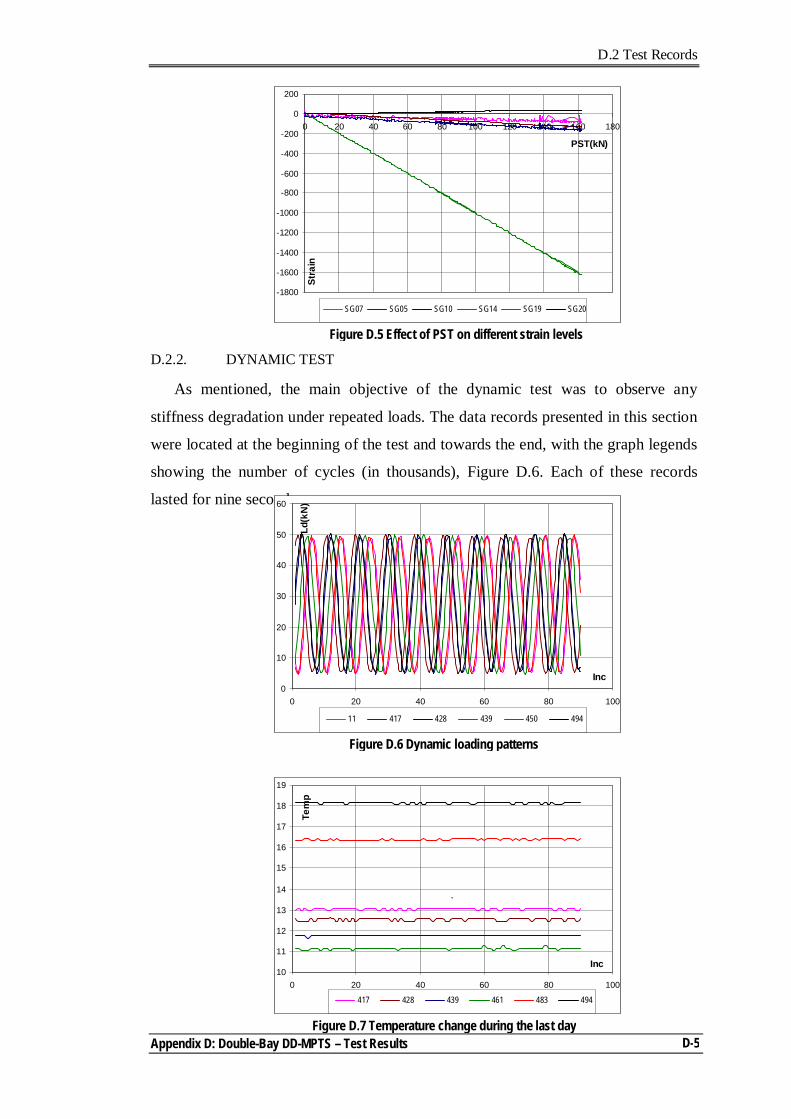
D.2 Test Records
Appendix D: Double-Bay DD-MPTS – Test Results
D-5
D.2.2. DYNAMIC TEST
As mentioned, the main objective of the dynamic test was to observe any
stiffness degradation under repeated loads. The data records presented in this section
were located at the beginning of the test and towards the end, with the graph legends
showing the number of cycles (in thousands), Figure D.6. Each of these records
lasted for nine seconds.
0
10
20
30
40
50
60
0 20 40 60 80 100
Inc
Ld(k
N)
11 417 428 439 450 494
Figure D.6 Dynamic loading patterns
-1800
-1600
-1400
-1200
-1000
-800
-600
-400
-200
0
200
0 20 40 60 80 100 120 140 160 180
PST(kN)
Stra
inSG07 SG05 SG10 SG14 SG19 SG20
Figure D.5 Effect of PST on different strain levels
Figure D.7 Temperature change during the last day
10
11
12
13
14
15
16
17
18
19
0 20 40 60 80 100
Inc
Tem
p
417 428 439 461 483 494
`
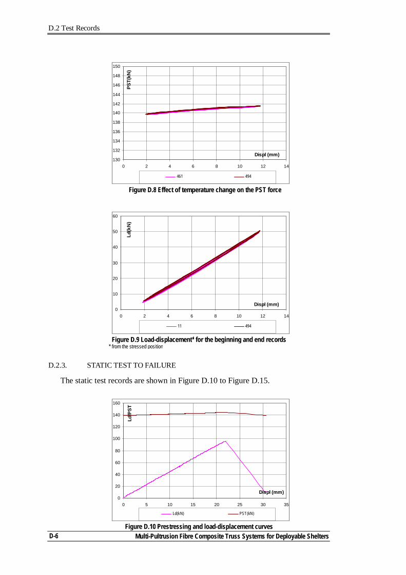
D.2 Test Records
Multi-Pultrusion Fibre Composite Truss Systems for Deployable Shelters
D-6
D.2.3. STATIC TEST TO FAILURE
The static test records are shown in Figure D.10 to Figure D.15.
0
10
20
30
40
50
60
0 2 4 6 8 10 12 14
Displ (mm)
Ld(k
N)
11 494
Figure D.9 Load-displacement* for the beginning and end records * from the stressed position
Figure D.10 Prestressing and load-displacement curves
0
20
40
60
80
100
120
140
160
0 5 10 15 20 25 30 35
Displ (mm)
Ld/P
ST
Ld(kN) PST(kN)
Figure D.8 Effect of temperature change on the PST force
130
132
134
136
138
140
142
144
146
148
150
0 2 4 6 8 10 12 14
Displ (mm)
PST(
kN)
461 494
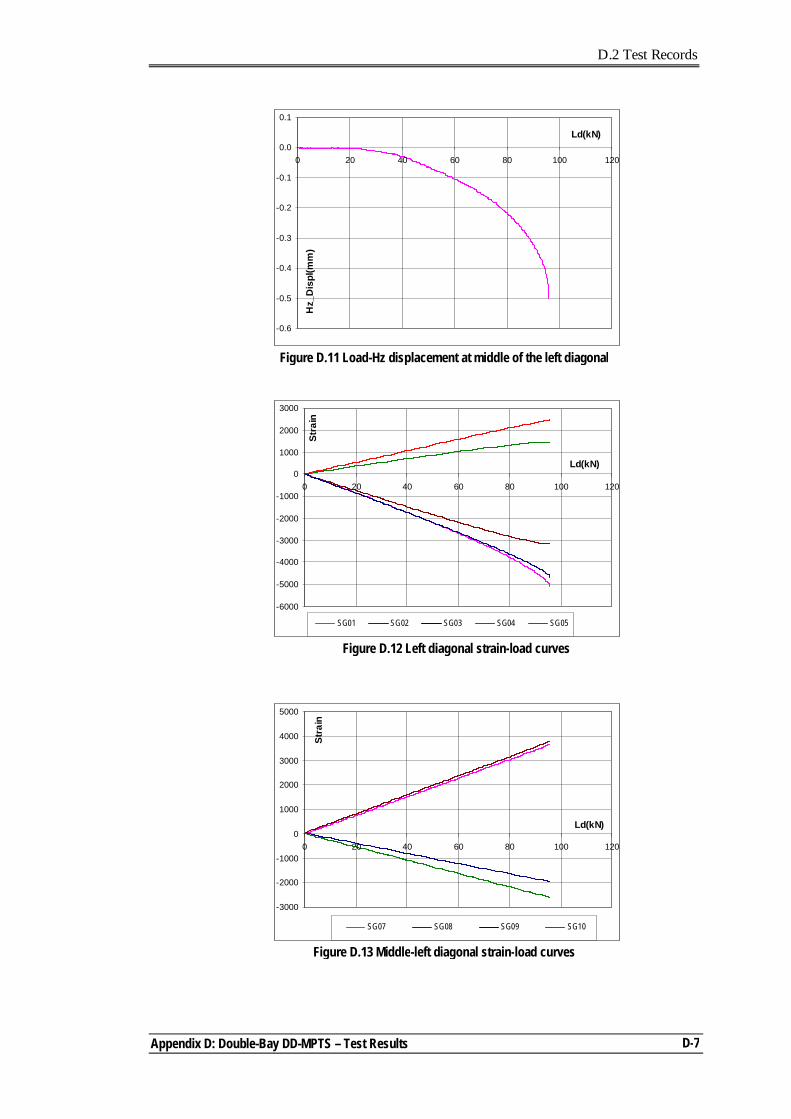
D.2 Test Records
Appendix D: Double-Bay DD-MPTS – Test Results
D-7
-0.6
-0.5
-0.4
-0.3
-0.2
-0.1
0.0
0.1
0 20 40 60 80 100 120
Ld(kN)
Hz_
Dis
pl(m
m)
Figure D.11 Load-Hz displacement at middle of the left diagonal
-6000
-5000
-4000
-3000
-2000
-1000
0
1000
2000
3000
0 20 40 60 80 100 120
Ld(kN)
Stra
in
SG01 SG02 SG03 SG04 SG05
Figure D.12 Left diagonal strain-load curves
Figure D.13 Middle-left diagonal strain-load curves
-3000
-2000
-1000
0
1000
2000
3000
4000
5000
0 20 40 60 80 100 120
Ld(kN)
Stra
in
SG07 SG08 SG09 SG10
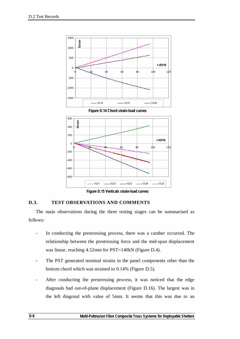
D.2 Test Records
Multi-Pultrusion Fibre Composite Truss Systems for Deployable Shelters
D-8
D.3. TEST OBSERVATIONS AND COMMENTS
The main observations during the three testing stages can be summarised as
follows:
- In conducting the prestressing process, there was a camber occurred. The
relationship between the prestressing force and the mid-span displacement
was linear, reaching 4.52mm for PST=140kN (Figure D.4).
- The PST generated nominal strains in the panel components other than the
bottom chord which was strained to 0.14% (Figure D.5).
- After conducting the prestressing process, it was noticed that the edge
diagonals had out-of-plane displacement (Figure D.16). The largest was in
the left diagonal with value of 5mm. It seems that this was due to an
Figure D.14 Chord strain-load curves
-1500
-1000
-500
0
500
1000
1500
0 20 40 60 80 100 120
Ld(kN)
Stra
in
SG14 SG15 SG20
Figure D.15 Verticals strain-load curves
-800
-600
-400
-200
0
200
400
600
0 20 40 60 80 100 120
Ld(kN)
Stra
in
SG21 SG22 SG23 SG24 SG25
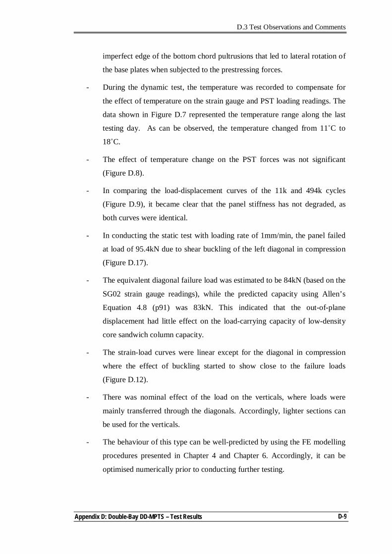
D.3 Test Observations and Comments
Appendix D: Double-Bay DD-MPTS – Test Results
D-9
imperfect edge of the bottom chord pultrusions that led to lateral rotation of
the base plates when subjected to the prestressing forces.
- During the dynamic test, the temperature was recorded to compensate for
the effect of temperature on the strain gauge and PST loading readings. The
data shown in Figure D.7 represented the temperature range along the last
testing day. As can be observed, the temperature changed from 11˚C to
18˚C.
- The effect of temperature change on the PST forces was not significant
(Figure D.8).
- In comparing the load-displacement curves of the 11k and 494k cycles
(Figure D.9), it became clear that the panel stiffness has not degraded, as
both curves were identical.
- In conducting the static test with loading rate of 1mm/min, the panel failed
at load of 95.4kN due to shear buckling of the left diagonal in compression
(Figure D.17).
- The equivalent diagonal failure load was estimated to be 84kN (based on the
SG02 strain gauge readings), while the predicted capacity using Allen’s
Equation 4.8 (p91) was 83kN. This indicated that the out-of-plane
displacement had little effect on the load-carrying capacity of low-density
core sandwich column capacity.
- The strain-load curves were linear except for the diagonal in compression
where the effect of buckling started to show close to the failure loads
(Figure D.12).
- There was nominal effect of the load on the verticals, where loads were
mainly transferred through the diagonals. Accordingly, lighter sections can
be used for the verticals.
- The behaviour of this type can be well-predicted by using the FE modelling
procedures presented in Chapter 4 and Chapter 6. Accordingly, it can be
optimised numerically prior to conducting further testing.
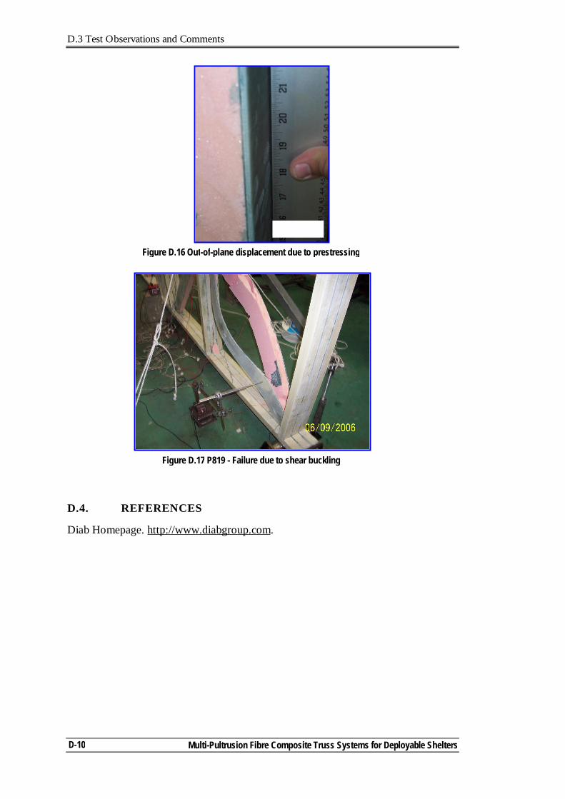
D.3 Test Observations and Comments
Multi-Pultrusion Fibre Composite Truss Systems for Deployable Shelters
D-10
D.4. REFERENCES
Diab Homepage. http://www.diabgroup.com.
Figure D.17 P819 - Failure due to shear buckling
Figure D.16 Out-of-plane displacement due to prestressing
Related Documents