1 General The Multi-outlet Swirl diffusers are design- ed for the supply of air in ventilation or air conditioning systems which have high air change rate requirements. High cooling loads can be achieved due to high induction ability. High degree of air coverage with mini- mum distance between diffusers. Symmetrical low room air movement in the occupied zone with high air change rates. Air flow rate range: 33–180 I.s -1 (120–650 m 3 .h -1 ) Mounting height: 3,0–4,0 m Temp. diff. supply to room air: + 8 K Cooling – 8 K Heating Function Each of the individual swirl diffusers pro- duce separate swirling jets which create a high induction at the outlet of the diffuser resulting in horizontal air patterns. At the inner section of the diffuser matrix the horizontal air patterns converge and subsequently form vertical air pattern be- low the diffuser. Through pre-determined selection of the arrangement of the individual diffuser ele- ments, various air patterns can be obtain- ed. Available sizes Size 4 Size 9 Multi-outlet Swirl diffuser type DFA Air diffusion systems

Welcome message from author
This document is posted to help you gain knowledge. Please leave a comment to let me know what you think about it! Share it to your friends and learn new things together.
Transcript
11
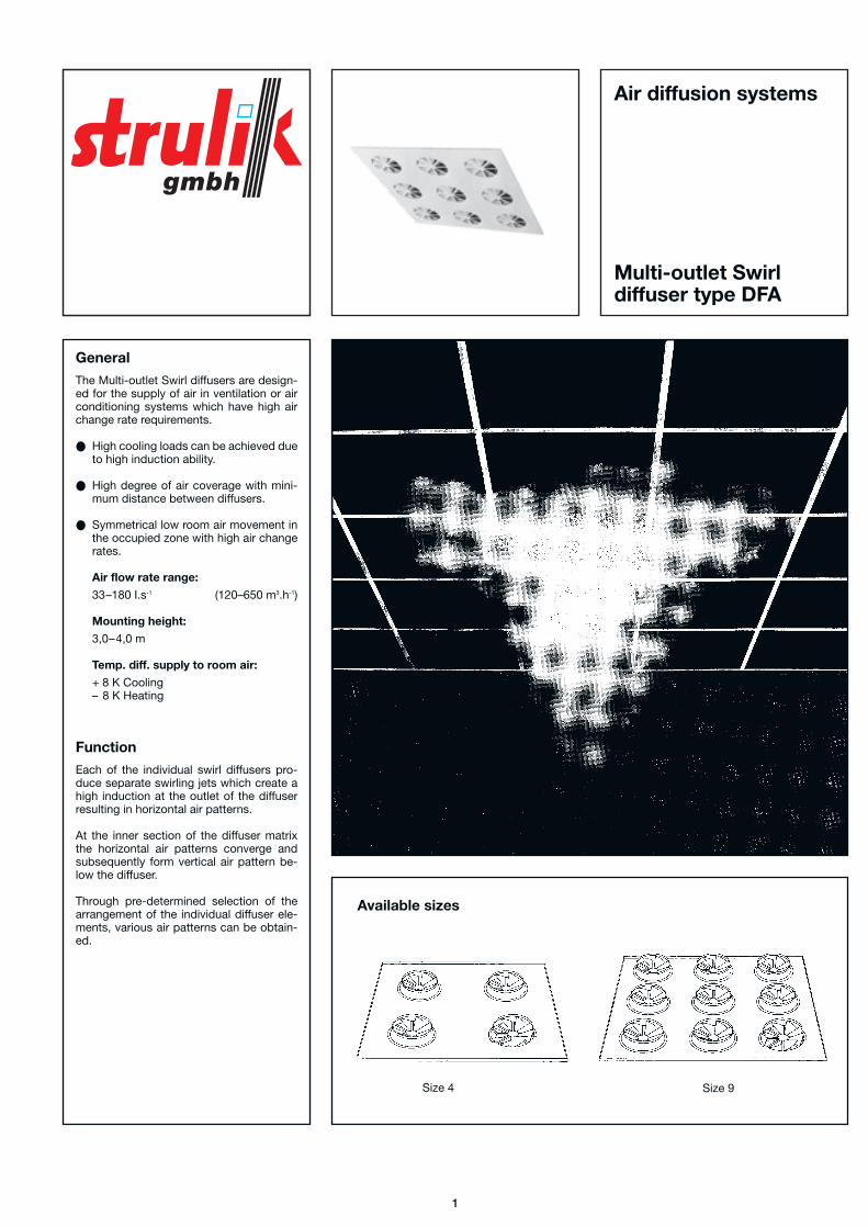
GeneralThe Multi-outlet Swirl diffusers are design-ed for the supply of air in ventilation or airconditioning systems which have high airchange rate requirements.
High cooling loads can be achieved dueto high induction ability.
High degree of air coverage with mini-mum distance between diffusers.
Symmetrical low room air movement inthe occupied zone with high air changerates.
Air flow rate range:
33–180 I.s-1 (120–650 m3.h-1)
Mounting height:
3,0–4,0 m
Temp. diff. supply to room air:
+ 8 K Cooling– 8 K Heating
FunctionEach of the individual swirl diffusers pro-duce separate swirling jets which create ahigh induction at the outlet of the diffuserresulting in horizontal air patterns.
At the inner section of the diffuser matrixthe horizontal air patterns converge andsubsequently form vertical air pattern be-low the diffuser.
Through pre-determined selection of thearrangement of the individual diffuser ele-ments, various air patterns can be obtain-ed.
Available sizes
Size 4 Size 9
Multi-outlet Swirldiffuser type DFA
Air diffusion systems
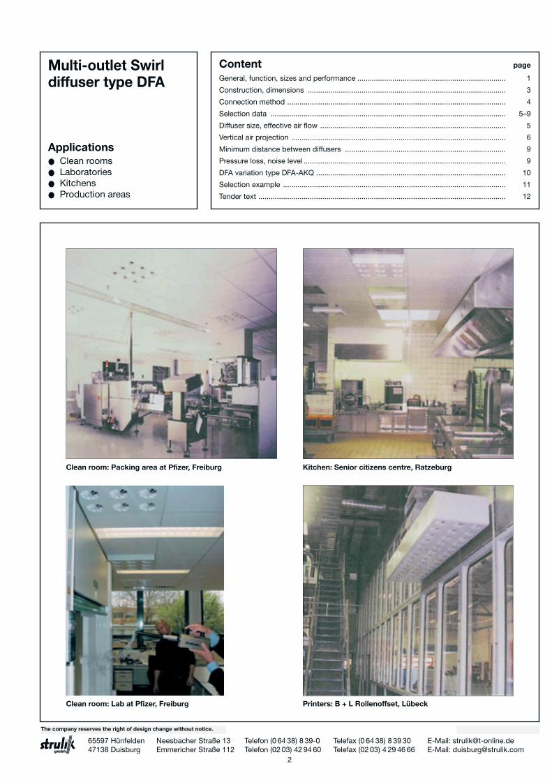
Clean room: Packing area at Pfizer, Freiburg
Clean room: Lab at Pfizer, Freiburg Printers: B + L Rollenoffset, Lübeck
Kitchen: Senior citizens centre, Ratzeburg
2
Multi-outlet Swirldiffuser type DFA
Applications● Clean rooms● Laboratories● Kitchens● Production areas
Content page
General, function, sizes and performance ........................................................................ 1
Construction, dimensions ................................................................................................ 3
Connection method .......................................................................................................... 4
Selection data .................................................................................................................. 5–9
Diffuser size, effective air flow .......................................................................................... 5
Vertical air projection ........................................................................................................ 6
Minimum distance between diffusers .............................................................................. 9
Pressure loss, noise level .................................................................................................. 9
DFA variation type DFA-AKQ ............................................................................................ 10
Selection example ............................................................................................................ 11
Tender text ........................................................................................................................ 12
06.02/6df2/2.000/GD/5/3The company reserves the right of design change without notice.
65597 Hünfelden Neesbacher Straße 13 Telefon (0 64 38) 8 39-0 Telefax (0 64 38) 8 39 30 E-Mail: [email protected] Duisburg Emmericher Straße 112 Telefon (02 03) 42 94 60 Telefax (02 03) 4 29 46 66 E-Mail: [email protected]

Construction and dimensions
The Multi-outlet Swirl diffuser DFA consists ofthe diffusion plate (1), into which are installed,depending on the nominal size, either 4 or 9 individual size 125 swirl diffusers (2).
The air flow pattern, especially the verticalprojection, can be varied by means of perfo-rated plates installed at the upstream entry tothe diffuser element (3).
The Multi-outlet Swirl diffusers DFA are also available in stainless steel.
Diffusion plate
Swirl diffuser
Perforated plate
Assembly fixing screw
1
2
3
4
Size 4 Size 9
Construction anddimensions
3
G (mm) Style
515 Standard
594 600 sq. lay-in tile module
619 625 sq. lay-in tile module
600 600 sq. tile module
625 625 sq. tile module
G (mm) Style
594 600 sq. lay-in tile module
619 625 sq. lay-in tile module
600 600 sq. tile module
625 625 sq. ltile module
Multi-outlet Swirldiffuser type DFA
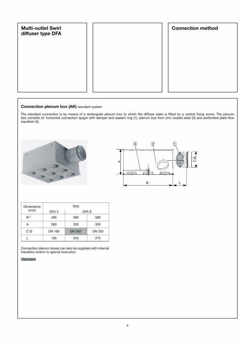
Connection plenum box (AK) standard system
The standard connection is by means of a rectangular plenum box to which the diffuser plate is fitted by a central fixing screw. The plenum box consists of: horizontal connection spigot with damper and sealant ring (1), plenum box from zinc coated steel (2) and perforated plate flow equaliser (3).
Dimensions(mm)
Size
DFA 4
495 580
350
DN 200*
225
260
DN 160
185
DFA 9
B
A
C Ø
580
350
DN 250
275L
Connection plenum boxes can also be supplied with internalinsulation and/or to special execution.
*Standard
Connection method
4
Multi-outlet Swirldiffuser type DFA
B ■ L
Selection data
In order to achieve the required air flow pattern in the occupied zone it is necessary to take the following into consideration.
● Selection of the correct size of diffuser
● Vertical air projection as a function of:– Air flow rate– Air flow pattern setting at the diffuser (only for size DFA 9)– Temperature difference, supply air – room air
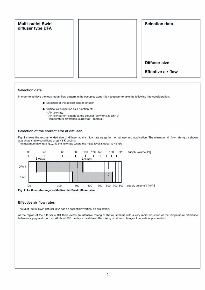
Selection of the correct size of diffuser
Fig. 1 shows the recommended size of diffuser against flow rate range for normal use and application. The minimum air flow rate (qmin) shown guarantee stable conditions at �t = 8 K cooling.The maximum flow rate (qmax) is the flow rate where the noise level is equal to 45 NR.
Fig. 1: Air flow rate range vs Multi-outlet Swirl diffuser size.
Effective air flow rates
The Multi-outlet Swirl diffuser DFA has an essentially vertical air projection.
At the region of the diffuser outlet there exists an intensive mixing of the air streams with a very rapid reduction of the temperature difference between supply and room air. At about 100 mm from the diffuser the mixing air stream changes to a vertical piston effect.
Selection data
Diffuser size
Effective air flow
5
Multi-outlet Swirldiffuser type DFA
DFA 4
DFA 9
30 40 60 80 100 120 140 180 220 supply volume [l/s]
100 200 300 400 500 600 700 800 supply volume [m3/h]V.
V.➞
max.V.➞
min.
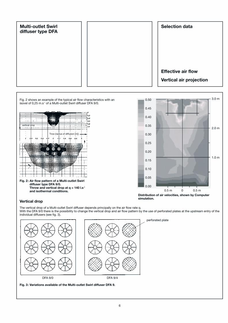
Fig. 2 shows an example of the typical air flow characteristics with an isovel of 0,25 m.s-1 of a Multi-outlet Swirl diffuser DFA 9/0.
Fig. 2 : Air flow pattern of a Multi-outlet Swirldiffuser type DFA 9/0.Throw and vertical drop at q = 140 l.s-1
and isothermal conditions.
Vertical drop
The vertical drop of a Multi-outlet Swirl diffuser depends principally on the air flow rate q.With the DFA 9/0 there is the possibility to change the vertical drop and air flow pattern by the use of perforated plates at the upstream entry of theindividual diffusers (see fig. 3).
Fig. 3 : Variations available of the Multi-outlet Swirl diffuser DFA 9.
6
DFA 9/0 DFA 9/4
Selection data
Effective air flow
Vertical air projection
Multi-outlet Swirldiffuser type DFA
Trow (radius of diffusion [m])
vertical drop
0.50
0.45
0.40
0.35
0.30
0.25
0.20
0.15
0.10
0.05
0.00
3.0 m
2.0 m
1.0 m
0.5 m 0 0.5 m
Distribution of air velocities, shown by Computer simulation.
perforated plate
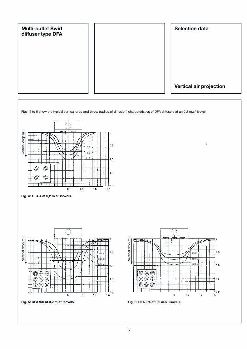
Figs. 4 to 6 show the typical vertical drop and throw (radius of diffusion) characteristics of DFA diffusers at an 0,2 m.s-1 isovel.
Fig. 4 : DFA 4 at 0,2 m.s-1 isovels.
Fig. 5: DFA 9/0 at 0,2 m.s-1 isovels. Fig. 6: DFA 9/4 at 0,2 m.s-1 isovels.
7
Selection data
Vertical air projection
Multi-outlet Swirldiffuser type DFA
Vert
ical
dro
p m
Vert
ical
dro
p m
Vert
ical
dro
p m
55 l.s-1
80 l.s-1
110 l.s-1
110 l.s-1
160 l.s-1
220 l.s-1
110 l.s-1
160 l.s-1
220 l.s-1
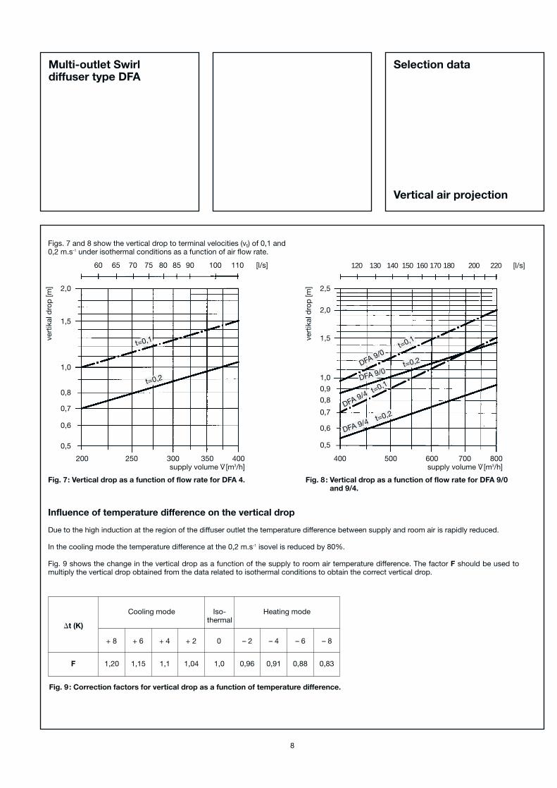
Fig. 7: Vertical drop as a function of flow rate for DFA 4. Fig. 8 : Vertical drop as a function of flow rate for DFA 9/0and 9/4.
Fig. 9 : Correction factors for vertical drop as a function of temperature difference.
Figs. 7 and 8 show the vertical drop to terminal velocities (vt) of 0,1 and 0,2 m.s-1 under isothermal conditions as a function of air flow rate.
Influence of temperature difference on the vertical drop
Due to the high induction at the region of the diffuser outlet the temperature difference between supply and room air is rapidly reduced.
In the cooling mode the temperature difference at the 0,2 m.s-1 isovel is reduced by 80%.
Fig. 9 shows the change in the vertical drop as a function of the supply to room air temperature difference. The factor F should be used to multiply the vertical drop obtained from the data related to isothermal conditions to obtain the correct vertical drop.
Cooling mode
�t (K)
F
Heating modeIso-thermal
+ 8
1,20 1,15 1,1 1,04 1,0 0,96 0,91 0,88 0,83
+ 6 + 4 + 2 0 – 2 – 4 – 6 – 8
8
Selection data
Vertical air projection
Multi-outlet Swirldiffuser type DFA
60 65 70 75 80 85 90 100 110 [l/s]
200 250 300 350 400supply volume V
. [m3/h]
2,0
1,5
1,0
0,8
0,7
0,6
0,5
vert
ikal
dro
p [m
]
t=0,1
t=0,2
120 130 140 150 160 170 180 200 220 [l/s]
400 500 600 700 800supply volume V
. [m3/h]
2,5
2,0
1,5
1,0
0,9
0,8
0,7
0,6
0,5
vert
ikal
dro
p [m
]
t=0,1
DFA 9/0
t=0,2
DFA 9/4
t=0,2
DFA 9/0
t=0,1
DFA 9/4

Pressure loss and noise level
Figs. 10 an 11 show the total pressure loss and noise levels for thecomplete diffuser assembly of Multi-outlet Swirl diffuser andconnection plenum.
Fig. 10: Total pressure loss (Pa) and noise levels (NR) for Multi-outlet Swirl diffuser DFA 4.
Fig. 11: Total pressure loss (Pa) and noise levels (NR) for Multi-outlet Swirl diffusers DFA 9 (DFA 9/0 and DFA 9/4).
Minimum distance between diffusers
The minimum distance between 2 diffusers is dependent on the radius of diffusion from the diffuser. Multi-outlet Swirl diffusers have, due to the con-verging air jets, a very small radius of diffusion. Therefore the minimum distance between diffusers is also very small.
For Multi-outlet Swirl diffusers there is a constant minimum distance between diffusers:
tmin = 1,25 m = constant
9
Selection data
Minimum distancebetween diffusers
Pressure lossNoise level
Multi-outlet Swirldiffuser type DFA
45 50 60 70 80 90 100 120 [l/s]
150 200 300 400 450supply volume V
. [m3/h]
100
807060
50
40
30
20
10
pre
ssur
e d
rop
Δp
t[P
a]
100 110 120 140 160 180 200 220 [l/s]
350 400 500 600 700 800supply volume V
. [m3/h]
100
80
60
50
40
30
20
10
pre
ssur
e d
rop
Δp
t[P
a]
NR 25
NR 30
NR 35
NR 40
NR 45
NR 50
NR 30
NR 35
NR 40
NR 45
NR 50

DFA Variation type DFA-AKQ
For high air flow rates (qv � 330I.s-1 – � 1200 m3.h-1) the DFA 9 is available in thespecial version DFA-AKQ which has an extended section with perforated plate tosimulate a displacement effect. 50% of thesupply air passes through the Swirl diffuserelements and 50% through the perforatedplate section.
Air flow rate range =125–330 I.s-1 (450–1250 m3.h-1)
The connection plenum is fitted with 2Ø200 inlet spigots at 90º to each other.
Vertical air projectionThe vertical air projection is determined bythe 50% of the supply air which passesthrough the Swirl diffuser elements and canbe established by the data in Figs. 5 to 9.
Example:Total flow rate = 280 I.s-1 (1008 m3.h-1)amount passing through the elements:140 I.s-1 (554 m3.h-1)from Fig. 5 or 8 the vertical drop can beread for vt0,2 of 1 m.
From Fig. 12 NR = 38 and PI = 42 Pa.
Distance between diffusersFor the DFA-AKQ there is a constant mini-mum distance between diffusers:
tmin = 1,75 m = constant
Noise level and pressure loss
Fig. 12: Total pressure loss (Pa) and noise levels (NR) forMulti-outlet Swirl diffuser DFA-AKQ 9
10
DN
200
(2 p
iece
s)
350
70
625(600, 585, 560)
dimensions on request
DFA Variationtype DFA-AKQ
Multi-outlet Swirldiffuser type DFA
120 140 160 200 240 300 340 [l/s]
400 500 600 700 800 1000 1250supply volume V
. [m3/h]
80
7060
50
40
30
20
10
pre
ssur
e d
rop
Δp
t[P
a]
NR 20
NR 25
NR 30
NR 35
NR 40
NR 45
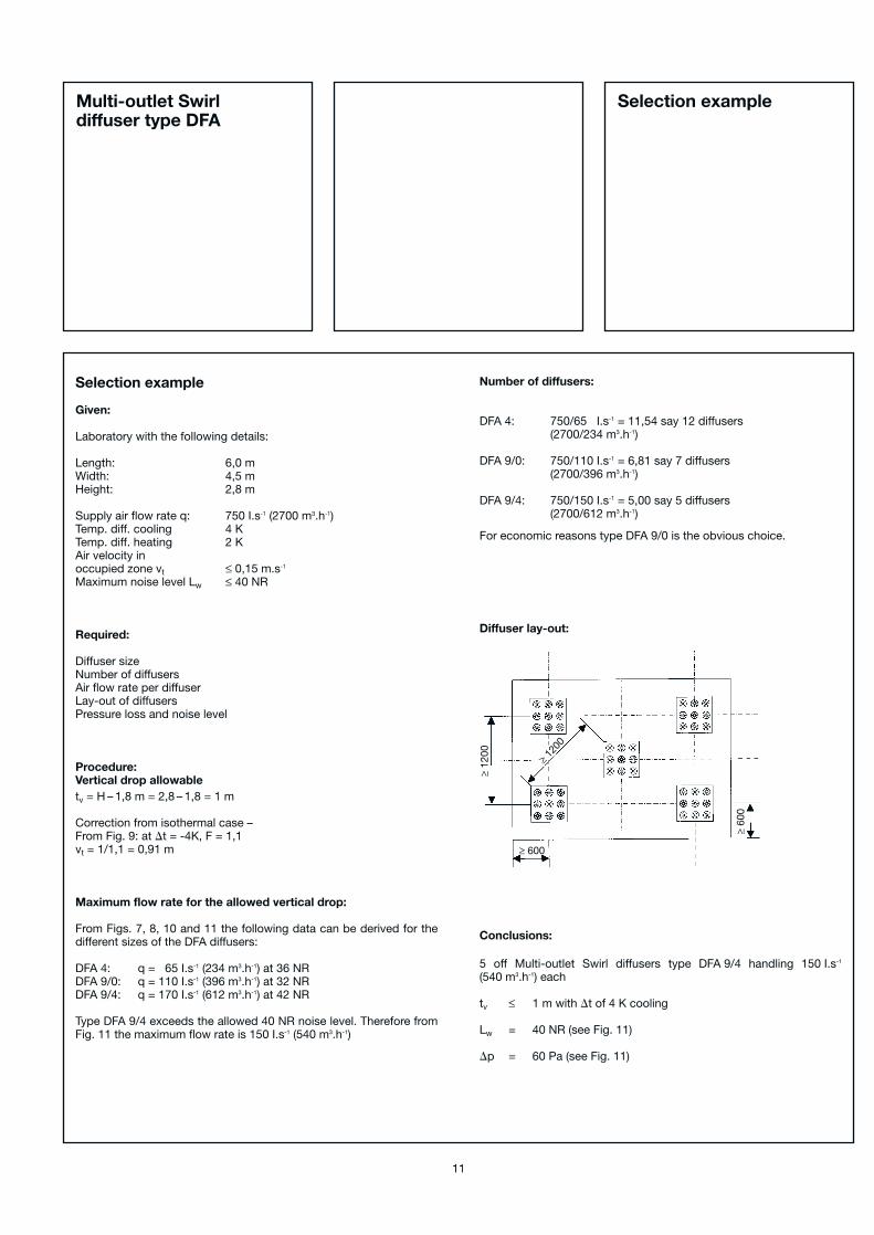
Selection example
Given:
Laboratory with the following details:
Length: 6,0 mWidth: 4,5 mHeight: 2,8 m
Supply air flow rate q: 750 I.s-1 (2700 m3.h-1)Temp. diff. cooling 4 KTemp. diff. heating 2 KAir velocity inoccupied zone vt ≤ 0,15 m.s-1
Maximum noise level Lw ≤ 40 NR
Required:
Diffuser sizeNumber of diffusersAir flow rate per diffuserLay-out of diffusersPressure loss and noise level
Procedure:Vertical drop allowabletv = H – 1,8 m = 2,8 – 1,8 = 1 m
Correction from isothermal case –From Fig. 9: at �t = -4K, F = 1,1vt = 1/1,1 = 0,91 m
Maximum flow rate for the allowed vertical drop:
From Figs. 7, 8, 10 and 11 the following data can be derived for thedifferent sizes of the DFA diffusers:
DFA 4: q = 65 I.s-1 (234 m3.h-1) at 36 NRDFA 9/0: q = 110 I.s-1 (396 m3.h-1) at 32 NRDFA 9/4: q = 170 I.s-1 (612 m3.h-1) at 42 NR
Type DFA 9/4 exceeds the allowed 40 NR noise level. Therefore fromFig. 11 the maximum flow rate is 150 I.s-1 (540 m3.h-1)
Number of diffusers:
DFA 4: 750/65 I.s-1 = 11,54 say 12 diffusers(2700/234 m3.h-1)
DFA 9/0: 750/110 I.s-1 = 6,81 say 7 diffusers(2700/396 m3.h-1)
DFA 9/4: 750/150 I.s-1 = 5,00 say 5 diffusers(2700/612 m3.h-1)
For economic reasons type DFA 9/0 is the obvious choice.
Diffuser lay-out:
Conclusions:
5 off Multi-outlet Swirl diffusers type DFA 9/4 handling 150 I.s-1
(540 m3.h-1) each
tv ≤ 1 m with �t of 4 K cooling
Lw = 40 NR (see Fig. 11)
�p = 60 Pa (see Fig. 11)
11
≥12
00
≥ 1200
≥ 600
≥60
0
Selection exampleMulti-outlet Swirldiffuser type DFA
12
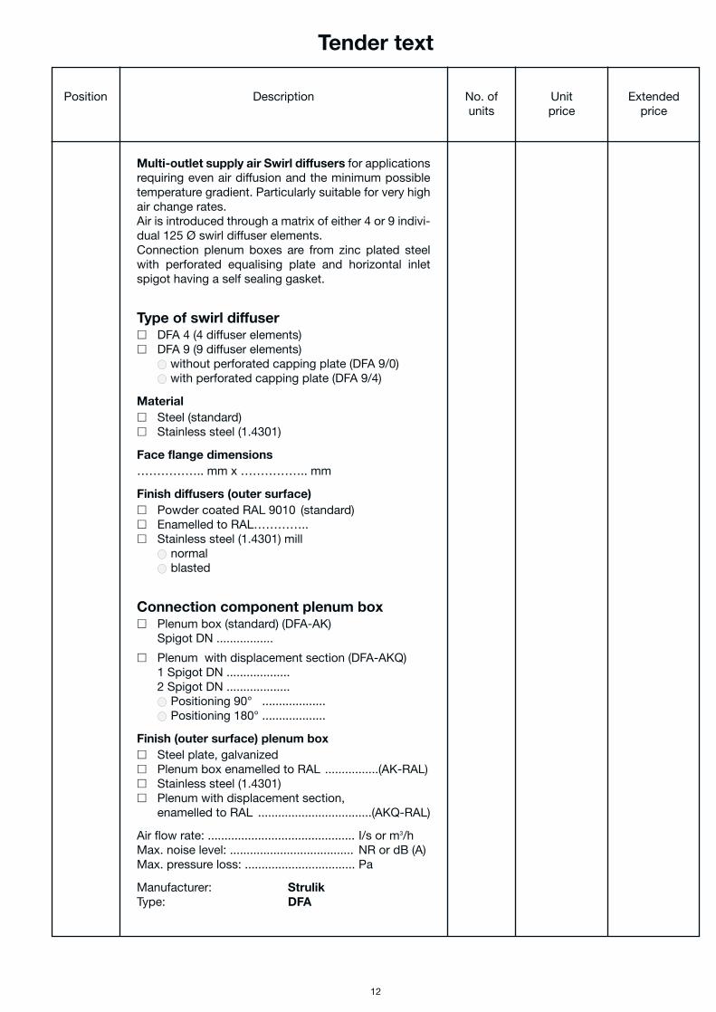
Tender text
Position Description No. of Unit Extendedunits price price
Multi-outlet supply air Swirl diffusers for applicationsrequiring even air diffusion and the minimum possibletemperature gradient. Particularly suitable for very highair change rates.Air is introduced through a matrix of either 4 or 9 indivi-dual 125 Ø swirl diffuser elements.Connection plenum boxes are from zinc plated steelwith perforated equalising plate and horizontal inletspigot having a self sealing gasket.
Type of swirl diffuser� DFA 4 (4 diffuser elements)� DFA 9 (9 diffuser elements)
● without perforated capping plate (DFA 9/0)● with perforated capping plate (DFA 9/4)
Material� Steel (standard)� Stainless steel (1.4301)
Face flange dimensions…………….. mm x …………….. mm
Finish diffusers (outer surface)� Powder coated RAL 9010 (standard)� Enamelled to RAL………….. � Stainless steel (1.4301) mill
● normal● blasted
Connection component plenum box� Plenum box (standard) (DFA-AK)
Spigot DN .................
� Plenum with displacement section (DFA-AKQ)1 Spigot DN ...................2 Spigot DN ...................● Positioning 90° ...................● Positioning 180° ...................
Finish (outer surface) plenum box� Steel plate, galvanized� Plenum box enamelled to RAL ................(AK-RAL)� Stainless steel (1.4301)� Plenum with displacement section,
enamelled to RAL ..................................(AKQ-RAL)
Air flow rate: ............................................ I/s or m3/hMax. noise level: ..................................... NR or dB (A)Max. pressure loss: ................................. Pa
Manufacturer: StrulikType: DFA
Related Documents