978-1-5090-1613-6/17/$31.00 ©2017 IEEE 1 Multi-Organization – Multi-Discipline Effort Developing a Mitigation Concept for Planetary Defense Ronald Y. Leung, Brent W. Barbee, Bernard D. Seery, Myra Bambacus NASA-Goddard Space Flight Center 8800 Greenbelt Road, Greenbelt, MD 20771 202-656-2077 [email protected] Lee Finewood, Kevin C. Greenaugh, Anthony Lewis National Nuclear Security Administration – Dept. of Energy / Forrestal Building 1000 Independence Ave. SW Washington, DC 20585 202-287-6584 [email protected] David S. P. Dearborn, Paul L. Miller Lawrence Livermore National Laboratory 7000 East Avenue / P.O, Box 808 Livermore, CA 94550 925-422-7219 [email protected] Robert P. Weaver, Catherine Plesko Los Alamos National Laboratory MS T087 / PO Box 1663 Los Alamos NM 87545 505-667-4756 [email protected] Abstract—There have been significant recent efforts in addressing mitigation approaches to neutralize Potentially Hazardous Asteroids (PHA). One such research effort was performed in 2015 by an integrated, inter-disciplinary team of asteroid scientists, energy deposition modeling scientists, payload engineers, orbital dynamicist engineers, spacecraft discipline engineers, and systems / architecture engineers from NASA’s Goddard Space Flight Center (GSFC) and the Department of Energy (DoE) / National Nuclear Security Administration (NNSA) laboratories (Los Alamos National Laboratory (LANL), Lawrence Livermore National Laboratories (LLNL) and Sandia National Laboratories). The study team collaborated with GSFC’s Integrated Design Center’s Mission Design Lab (MDL) which engaged a team of GSFC flight hardware discipline engineers to work with GSFC, LANL, and LLNL Near-Earth Asteroid (NEA)-related subject matter experts during a one-week intensive concept formulation study in an integrated concurrent engineering environment. This team has analyzed the first of several distinct study cases for a multi-year NASA research grant. This Case 1 study references the NEA named Bennu as the notional target due to the availability of a very detailed Design Reference Asteroid (DRA) model for its orbit and physical characteristics (courtesy of the Origins, Spectral Interpretation, Resource Identification, Security-Regolith Explorer [OSIRIS-REx] mission team). The research involved the formulation and optimization of spacecraft trajectories to intercept Bennu, overall mission and architecture concepts, and high-fidelity modeling of both kinetic impact (spacecraft collision to change a NEA’s momentum and orbit) and nuclear detonation effects on Bennu, for purposes of deflecting Bennu. TABLE OF CONTENTS 1. INTRODUCTION....................................................... 1 2. CONCEPT FORMULATION CONSTRAINTS AND DRIVERS ...................................................................... 2 3. TOP LEVEL MITIGATION FUNCTIONS (POST DETECTION) ................................................................ 3 4. MISSION TIMELINE ................................................ 4 5. AUTONOMOUS NAVIGATION SYSTEM ................... 4 6. ORBITAL PHYSICS .................................................. 5 7. FUNCTIONAL CONCEPT.......................................... 6 8. FUNCTIONAL ALLOCATION FOR CASE 1 ............... 7 9. ALTERNATIVE LAUNCH VEHICLES........................ 8 10. NOTIONAL SPACE SEGMENT DEVELOPMENT AND DEPLOYMENT TIMELINE (1 ST ARTICLE ONLY) 10 11. MISSION EFFECTIVENESS /MISSION SUCCESS .10 12. CONCEPT OF CAMPAIGN MODE......................... 11 13. TEAM FINDINGS .................................................. 12 14. SUMMARY............................................................ 17 ACKNOWLEDGEMENTS ............................................ 18 REFERENCES ............................................................. 18 BIOGRAPHY............................................................... 19 1. INTRODUCTION This paper is intended to be one of a set of papers to be produced by an integrated study team comprised of NASA/ GSFC, DoE/NNSA LANL, and LLNL, of work conducted in the October 2015 timeframe. We refer to results of a parallel paper on the uncertainty caused by physical properties of asteroids and how they respond to a deflection impulse. The focus of this paper is on the Delivery Segment and Space Segment portions of a larger NEA Mitigation Architecture as depicted in Figure 1. This activity produced a detailed concept of a multi-purpose spacecraft to carry out planetary defense mission objectives. While the Bennu scenario was utilized as a point of departure for analysis purposes, the spacecraft concept is intended to be applicable to a broader range of possible hazardous NEA scenarios. The MDL systems concept development study objectives included formulating a spacecraft concept capable of intercepting an NEA, functioning as either a Kinetic Impactor (KI) or a Nuclear Energy Device (NED) delivery system. The assumed target for this study is the Potentially Hazardous [to Earth] Asteroid (PHA) known as 101955 Bennu (1999 RQ36), which is the destination for NASA’s OSIRIS-REx asteroid sample return mission (launched in September 2016). [1] https://ntrs.nasa.gov/search.jsp?R=20170002017 2018-07-16T02:52:45+00:00Z

Welcome message from author
This document is posted to help you gain knowledge. Please leave a comment to let me know what you think about it! Share it to your friends and learn new things together.
Transcript

978-1-5090-1613-6/17/$31.00 ©2017 IEEE
1
Multi-Organization – Multi-Discipline EffortDeveloping a Mitigation Concept for Planetary Defense
Ronald Y. Leung, Brent W. Barbee,Bernard D. Seery, Myra Bambacus
NASA-Goddard Space Flight Center8800 Greenbelt Road,Greenbelt, MD 20771
Lee Finewood, Kevin C. Greenaugh, Anthony LewisNational Nuclear Security Administration –
Dept. of Energy / Forrestal Building1000 Independence Ave. SW
Washington, DC 20585202-287-6584
David S. P. Dearborn, Paul L. MillerLawrence Livermore National Laboratory
7000 East Avenue / P.O, Box 808Livermore, CA 94550
Robert P. Weaver, Catherine PleskoLos Alamos National Laboratory
MS T087 / PO Box 1663Los Alamos NM 87545
Abstract—There have been significant recent efforts inaddressing mitigation approaches to neutralize PotentiallyHazardous Asteroids (PHA). One such research effort wasperformed in 2015 by an integrated, inter-disciplinary team ofasteroid scientists, energy deposition modeling scientists,payload engineers, orbital dynamicist engineers, spacecraftdiscipline engineers, and systems / architecture engineers fromNASA’s Goddard Space Flight Center (GSFC) and theDepartment of Energy (DoE) / National Nuclear SecurityAdministration (NNSA) laboratories (Los Alamos NationalLaboratory (LANL), Lawrence Livermore NationalLaboratories (LLNL) and Sandia National Laboratories). Thestudy team collaborated with GSFC’s Integrated DesignCenter’s Mission Design Lab (MDL) which engaged a team ofGSFC flight hardware discipline engineers to work withGSFC, LANL, and LLNL Near-Earth Asteroid (NEA)-relatedsubject matter experts during a one-week intensive conceptformulation study in an integrated concurrent engineeringenvironment. This team has analyzed the first of severaldistinct study cases for a multi-year NASA research grant.This Case 1 study references the NEA named Bennu as thenotional target due to the availability of a very detailed DesignReference Asteroid (DRA) model for its orbit and physicalcharacteristics (courtesy of the Origins, SpectralInterpretation, Resource Identification, Security-RegolithExplorer [OSIRIS-REx] mission team). The research involvedthe formulation and optimization of spacecraft trajectories tointercept Bennu, overall mission and architecture concepts,and high-fidelity modeling of both kinetic impact (spacecraftcollision to change a NEA’s momentum and orbit) and nucleardetonation effects on Bennu, for purposes of deflecting Bennu.
TABLE OF CONTENTS
1. INTRODUCTION....................................................... 12. CONCEPT FORMULATION CONSTRAINTS ANDDRIVERS...................................................................... 23. TOP LEVEL MITIGATION FUNCTIONS (POSTDETECTION)................................................................ 34. MISSION TIMELINE ................................................ 45. AUTONOMOUS NAVIGATION SYSTEM ................... 46. ORBITAL PHYSICS .................................................. 57. FUNCTIONAL CONCEPT.......................................... 6
8. FUNCTIONAL ALLOCATION FOR CASE 1...............79. ALTERNATIVE LAUNCH VEHICLES........................810. NOTIONAL SPACE SEGMENT DEVELOPMENTAND DEPLOYMENT TIMELINE (1ST ARTICLE ONLY) 1011. MISSION EFFECTIVENESS / MISSION SUCCESS .1012. CONCEPT OF CAMPAIGN MODE.........................1113. TEAM FINDINGS ..................................................1214. SUMMARY............................................................17ACKNOWLEDGEMENTS ............................................18REFERENCES .............................................................18BIOGRAPHY...............................................................19
1. INTRODUCTION
This paper is intended to be one of a set of papers to beproduced by an integrated study team comprised of NASA/GSFC, DoE/NNSA LANL, and LLNL, of work conductedin the October 2015 timeframe. We refer to results of aparallel paper on the uncertainty caused by physicalproperties of asteroids and how they respond to a deflectionimpulse.
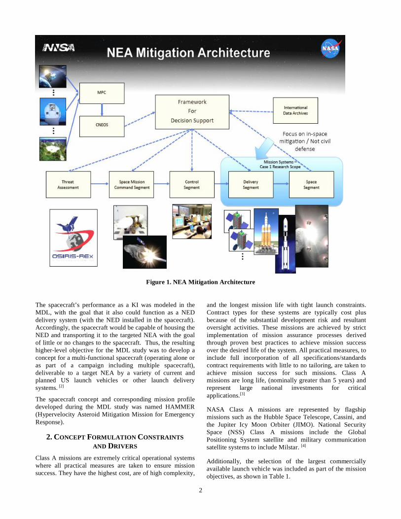
The focus of this paper is on the Delivery Segment andSpace Segment portions of a larger NEA MitigationArchitecture as depicted in Figure 1. This activity produceda detailed concept of a multi-purpose spacecraft to carry outplanetary defense mission objectives. While the Bennuscenario was utilized as a point of departure for analysispurposes, the spacecraft concept is intended to be applicableto a broader range of possible hazardous NEA scenarios.The MDL systems concept development study objectivesincluded formulating a spacecraft concept capable ofintercepting an NEA, functioning as either a KineticImpactor (KI) or a Nuclear Energy Device (NED) deliverysystem. The assumed target for this study is the PotentiallyHazardous [to Earth] Asteroid (PHA) known as 101955Bennu (1999 RQ36), which is the destination for NASA’sOSIRIS-REx asteroid sample return mission (launched inSeptember 2016). [1]
https://ntrs.nasa.gov/search.jsp?R=20170002017 2018-07-16T02:52:45+00:00Z
2
Figure 1. NEA Mitigation Architecture
The spacecraft’s performance as a KI was modeled in theMDL, with the goal that it also could function as a NEDdelivery system (with the NED installed in the spacecraft).Accordingly, the spacecraft would be capable of housing theNED and transporting it to the targeted NEA with the goalof little or no changes to the spacecraft. Thus, the resultinghigher-level objective for the MDL study was to develop aconcept for a multi-functional spacecraft (operating alone oras part of a campaign including multiple spacecraft),deliverable to a target NEA by a variety of current andplanned US launch vehicles or other launch deliverysystems. [2]
The spacecraft concept and corresponding mission profiledeveloped during the MDL study was named HAMMER(Hypervelocity Asteroid Mitigation Mission for EmergencyResponse).
2. CONCEPT FORMULATION CONSTRAINTSAND DRIVERS
Class A missions are extremely critical operational systemswhere all practical measures are taken to ensure missionsuccess. They have the highest cost, are of high complexity,
and the longest mission life with tight launch constraints.Contract types for these systems are typically cost plusbecause of the substantial development risk and resultantoversight activities. These missions are achieved by strictimplementation of mission assurance processes derivedthrough proven best practices to achieve mission successover the desired life of the system. All practical measures, toinclude full incorporation of all specifications/standardscontract requirements with little to no tailoring, are taken toachieve mission success for such missions. Class Amissions are long life, (nominally greater than 5 years) andrepresent large national investments for criticalapplications.[3]
NASA Class A missions are represented by flagshipmissions such as the Hubble Space Telescope, Cassini, andthe Jupiter Icy Moon Orbiter (JIMO). National SecuritySpace (NSS) Class A missions include the GlobalPositioning System satellite and military communicationsatellite systems to include Milstar. [4]
Additionally, the selection of the largest commerciallyavailable launch vehicle was included as part of the missionobjectives, as shown in Table 1.
3
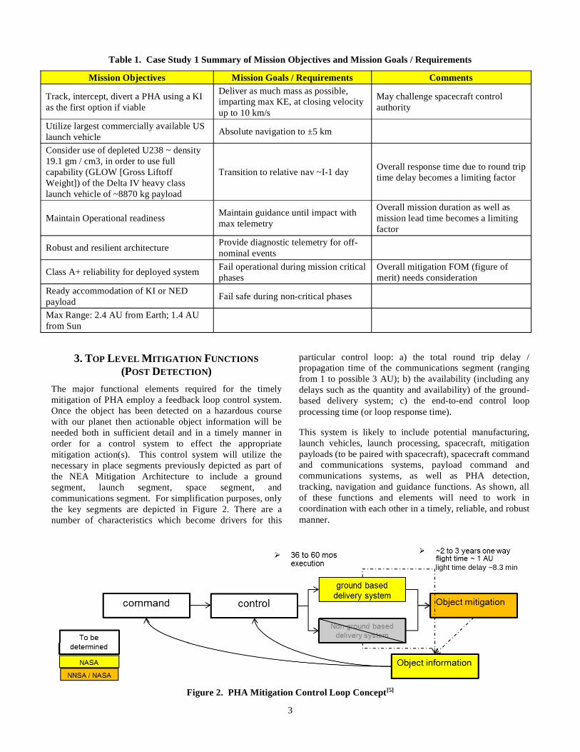
Table 1. Case Study 1 Summary of Mission Objectives and Mission Goals / Requirements
Mission Objectives Mission Goals / Requirements Comments
Track, intercept, divert a PHA using a KIas the first option if viable
Deliver as much mass as possible,imparting max KE, at closing velocityup to 10 km/s
May challenge spacecraft controlauthority
Utilize largest commercially available USlaunch vehicle Absolute navigation to ±5 km
Consider use of depleted U238 ~ density19.1 gm / cm3, in order to use fullcapability (GLOW [Gross LiftoffWeight]) of the Delta IV heavy classlaunch vehicle of ~8870 kg payload
Transition to relative nav ~I-1 day Overall response time due to round triptime delay becomes a limiting factor
Maintain Operational readiness Maintain guidance until impact withmax telemetry
Overall mission duration as well asmission lead time becomes a limitingfactor
Robust and resilient architecture Provide diagnostic telemetry for off-nominal events
Class A+ reliability for deployed system Fail operational during mission criticalphases
Overall mitigation FOM (figure ofmerit) needs consideration
Ready accommodation of KI or NEDpayload Fail safe during non-critical phases
Max Range: 2.4 AU from Earth; 1.4 AUfrom Sun
3. TOP LEVEL MITIGATION FUNCTIONS(POST DETECTION)
The major functional elements required for the timelymitigation of PHA employ a feedback loop control system.Once the object has been detected on a hazardous coursewith our planet then actionable object information will beneeded both in sufficient detail and in a timely manner inorder for a control system to effect the appropriatemitigation action(s). This control system will utilize thenecessary in place segments previously depicted as part ofthe NEA Mitigation Architecture to include a groundsegment, launch segment, space segment, andcommunications segment. For simplification purposes, onlythe key segments are depicted in Figure 2. There are anumber of characteristics which become drivers for this
particular control loop: a) the total round trip delay /propagation time of the communications segment (rangingfrom 1 to possible 3 AU); b) the availability (including anydelays such as the quantity and availability) of the ground-based delivery system; c) the end-to-end control loopprocessing time (or loop response time).
This system is likely to include potential manufacturing,launch vehicles, launch processing, spacecraft, mitigationpayloads (to be paired with spacecraft), spacecraft commandand communications systems, payload command andcommunications systems, as well as PHA detection,tracking, navigation and guidance functions. As shown, allof these functions and elements will need to work incoordination with each other in a timely, reliable, and robustmanner.
Figure 2. PHA Mitigation Control Loop Concept[5]
light time delay ~8.3 min
4
4. MISSION TIMELINE
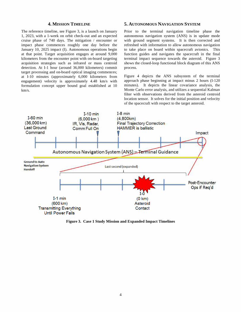
The reference timeline, see Figure 3, is a launch on January1, 2023, with a 1-week on orbit check-out and an expectedcruise phase of 740 days. The mitigation / encounter orimpact phase commences roughly one day before theJanuary 10, 2025 impact (I). Autonomous operations beginat that point. Target acquisition engages at around 9,000kilometers from the encounter point with on-board targetingacquisition strategies such as infrared or mass centroiddetection. At I-1 hour (around 36,000 kilometers) committarget processing and on-board optical imaging commences;at I-10 minutes (approximately 6,000 kilometers fromengagement) velocity is approximately 4.48 km/s withformulation concept upper bound goal established at 10km/s.
5. AUTONOMOUS NAVIGATION SYSTEM
Prior to the terminal navigation timeline phase theautonomous navigation system (ANS) is in update modewith ground segment systems. It is then corrected andrefreshed with information to allow autonomous navigationto take place on board within spacecraft avionics. Thisfunction guides and navigates the spacecraft in the finalterminal impact sequence towards the asteroid. Figure 3shows the closed-loop functional block diagram of this ANSprocess.
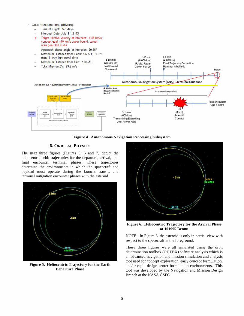
Figure 4 depicts the ANS subsystem of the terminalapproach phase beginning at impact minus 2 hours (I-120minutes). It depicts the linear covariance analysis, theMonte Carlo error analysis, and utilizes a sequential Kalmanfilter with observations derived from the asteroid centroidlocation sensor. It solves for the initial position and velocityof the spacecraft with respect to the target asteroid.
Figure 3. Case 1 Study Mission and Expanded Impact Timelines
5
Figure 4. Autonomous Navigation Processing Subsystem
6. ORBITAL PHYSICS
The next three figures (Figures 5, 6 and 7) depict theheliocentric orbit trajectories for the departure, arrival, andfinal encounter terminal phases. These trajectoriesdetermine the environments in which the spacecraft andpayload must operate during the launch, transit, andterminal mitigation encounter phases with the asteroid.
Figure 5. Heliocentric Trajectory for the EarthDeparture Phase
Figure 6. Heliocentric Trajectory for the Arrival Phaseat 101995 Bennu
NOTE: In Figure 6, the asteroid is only in partial view withrespect to the spacecraft in the foreground.
These three figures were all simulated using the orbitdetermination toolbox (ODTBX) software analysis which isan advanced navigation and mission simulation and analysistool used for concept exploration, early concept formulation,and/or rapid design center formulation environments. Thistool was developed by the Navigation and Mission DesignBranch at the NASA GSFC.
6
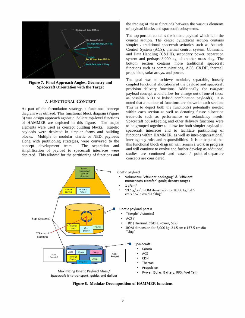
Figure 7. Final Approach Angles, Geometry andSpacecraft Orientation with the Target
7. FUNCTIONAL CONCEPT
As part of the formulation strategy, a functional conceptdiagram was utilized. This functional block diagram (Figure8) was design approach agnostic. Salient top-level functionsof HAMMER are depicted in this figure. The majorelements were used as concept building blocks. Kineticpayloads were depicted in simpler forms and buildingblocks. Multiple or modular kinetic or NED, payloadsalong with partitioning strategies, were conveyed to theconcept development team. The separation andsimplification of payload to spacecraft interfaces weredepicted. This allowed for the partitioning of functions and
the trading of these functions between the various elementsof payload blocks and spacecraft subsystems.
The top portion contains the kinetic payload which is in theconical section. The center cylindrical section containssimpler / traditional spacecraft avionics such as AttitudeControl System (ACS), thermal control system, Commandand Data Handling (C&DH), secondary power, separationsystem and perhaps 8,000 kg of another mass slug. Thebottom section contains more traditional spacecraftfunctions such as communications, ACS, C&DH, thermal,propulsion, solar arrays, and power.
The goal was to achieve modular, separable, looselycoupled functional allocations of the payload and spacecraftprecision delivery functions. Additionally, the two-partpayload concept would allow for change out of one of theseas possible NED or hybrid combination payload(s). It isnoted that a number of functions are shown in each section.This is to depict both the function(s) potentially neededwithin each section as well as denoting future allocationtrade-offs such as performance or redundancy needs.Spacecraft housekeeping and other delivery functions wereto be grouped together to allow for both simpler payload tospacecraft interfaces and to facilitate partitioning offunctions within HAMMER, as well as inter-organizational/inter-agency roles and responsibilities. It is anticipated thatthis functional block diagram will remain a work in progressand will continue to evolve and further develop as additionalstudies are continued and cases / point-of-departureconcepts are considered.
Figure 8. Modular Decomposition of HAMMER functions

7
8. FUNCTIONAL ALLOCATION FOR CASE 1Figure 9 depicts the current representation for the Case 1allocation of spacecraft functions and payload functions.Within the spacecraft there is a telecommunicationssubsystem, an avionics subsystem, propulsion subsystem,power subsystem, thermal subsystem, attitude controlsystem and a control and data handling subsystem. On thelower left is the interface to the NED or kinetic energydevice. It's a simpler interface to this modular exchangeablepayload. It is a concept goal that one-way data and powerare the only necessary interfaces for this modular payload.This concept should allow for modular exchange and verylate integration of this payload with the spacecraft. Internalto this payload, it is anticipated that the payload would haveits own batteries, control electronics, detection (camera-like)function and target acquisition system, as well as someinternal navigation detection systems.
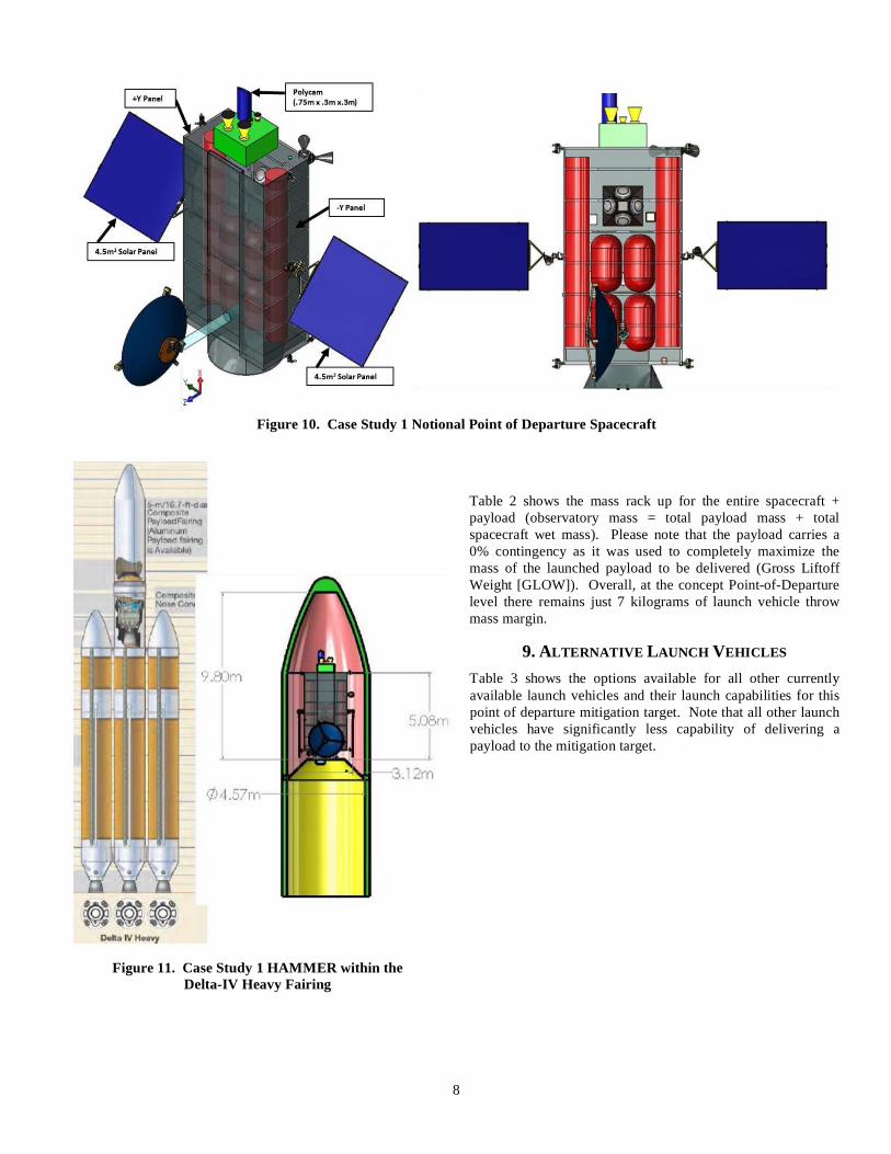
Figure 10 depicts the notional spacecraft concept. It is arectangular structure where the mechanical/structural loadsare carried along its length and through the center of thespacecraft with a thrust tube down the center. The potentialNEDs are along the sides. This allows deployment of theNEDs, if necessary. The attitude control thrusters are in thecorners of the spacecraft along with a propulsion system(+X axis) to allow release of the NEDs. The solar arrays andthe single high-gain antenna are fully gimbaled. This isneeded in order to maintain power from a distance of up to1.4 AU from the Sun and communicate to Earth at adistance of up to 2.4 AU.
Figure 11 shows the spacecraft in the launch configurationwithin the Delta-IV Heavy. It occupies only about two-thirds of the volume since the spacecraft mass isconcentrated. The overall fairing size of the Delta-IVHeavy is shown to be about 9.8 meters in length, about 4.6meters in diameter within the dynamic fairing envelope.The spacecraft is attached to a 3-meter fairing adapter. Theoverall spacecraft length is just over 5 meters.
Figure 9. Spacecraft Subsystems Functional Block Diagram as Allocated for the Case 1 Study
8
Figure 10. Case Study 1 Notional Point of Departure Spacecraft
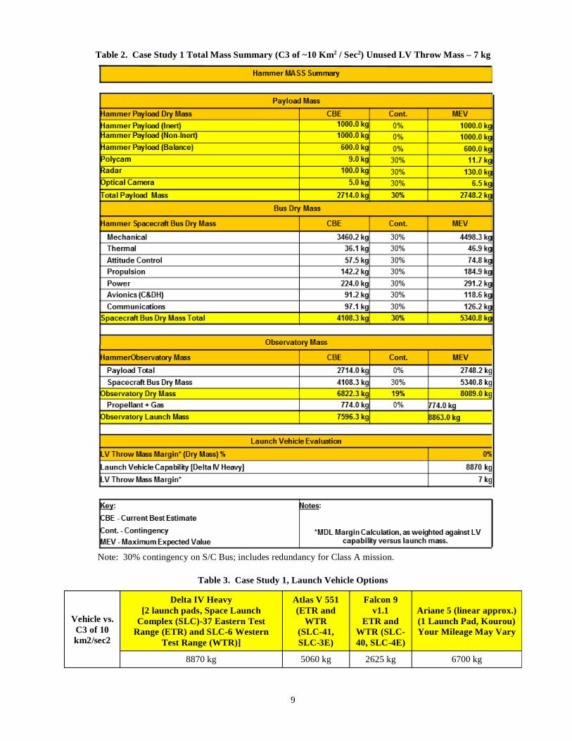
Table 2 shows the mass rack up for the entire spacecraft +payload (observatory mass = total payload mass + totalspacecraft wet mass). Please note that the payload carries a0% contingency as it was used to completely maximize themass of the launched payload to be delivered (Gross LiftoffWeight [GLOW]). Overall, at the concept Point-of-Departurelevel there remains just 7 kilograms of launch vehicle throwmass margin.
9. ALTERNATIVE LAUNCH VEHICLES
Table 3 shows the options available for all other currentlyavailable launch vehicles and their launch capabilities for thispoint of departure mitigation target. Note that all other launchvehicles have significantly less capability of delivering apayload to the mitigation target.
Figure 11. Case Study 1 HAMMER within theDelta-IV Heavy Fairing
9
Table 2. Case Study 1 Total Mass Summary (C3 of ~10 Km2 / Sec2) Unused LV Throw Mass – 7 kg
Note: 30% contingency on S/C Bus; includes redundancy for Class A mission.
Table 3. Case Study 1, Launch Vehicle Options
Vehicle vs.C3 of 10km2/sec2
Delta IV Heavy[2 launch pads, Space Launch
Complex (SLC)-37 Eastern TestRange (ETR) and SLC-6 Western
Test Range (WTR)]
Atlas V 551(ETR and
WTR(SLC-41,SLC-3E)
Falcon 9v1.1
ETR andWTR (SLC-40, SLC-4E)
Ariane 5 (linear approx.)(1 Launch Pad, Kourou)Your Mileage May Vary
8870 kg 5060 kg 2625 kg 6700 kg
10
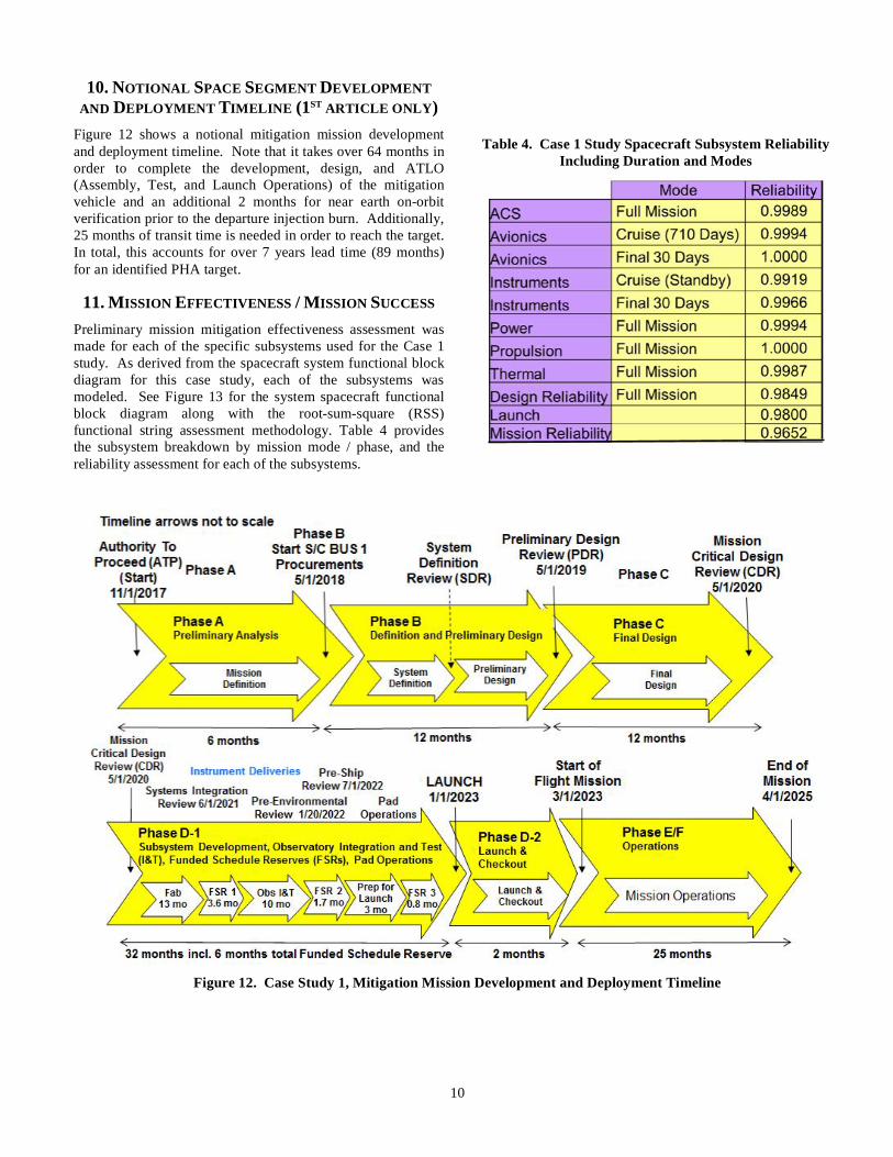
10. NOTIONAL SPACE SEGMENT DEVELOPMENTAND DEPLOYMENT TIMELINE (1ST ARTICLE ONLY)
Figure 12 shows a notional mitigation mission developmentand deployment timeline. Note that it takes over 64 months inorder to complete the development, design, and ATLO(Assembly, Test, and Launch Operations) of the mitigationvehicle and an additional 2 months for near earth on-orbitverification prior to the departure injection burn. Additionally,25 months of transit time is needed in order to reach the target.In total, this accounts for over 7 years lead time (89 months)for an identified PHA target.
11. MISSION EFFECTIVENESS / MISSION SUCCESS
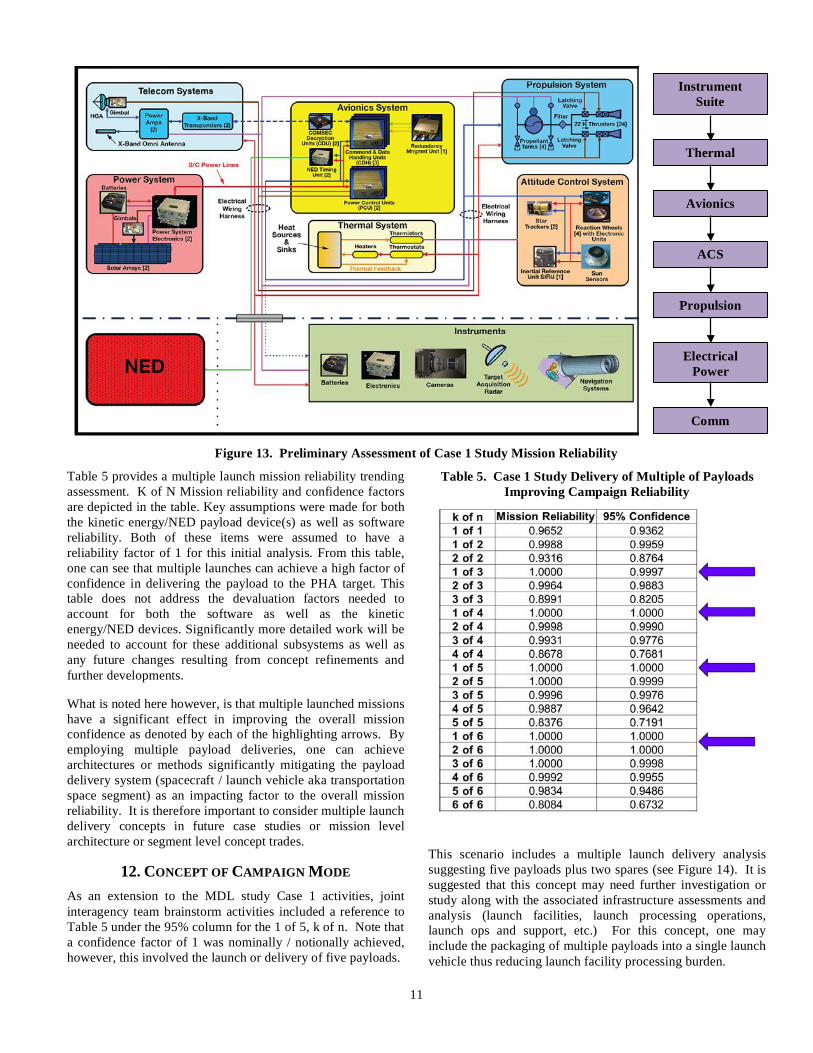
Preliminary mission mitigation effectiveness assessment wasmade for each of the specific subsystems used for the Case 1study. As derived from the spacecraft system functional blockdiagram for this case study, each of the subsystems wasmodeled. See Figure 13 for the system spacecraft functionalblock diagram along with the root-sum-square (RSS)functional string assessment methodology. Table 4 providesthe subsystem breakdown by mission mode / phase, and thereliability assessment for each of the subsystems.
Table 4. Case 1 Study Spacecraft Subsystem ReliabilityIncluding Duration and Modes
Figure 12. Case Study 1, Mitigation Mission Development and Deployment Timeline
11
Figure 13. Preliminary Assessment of Case 1 Study Mission Reliability
Table 5 provides a multiple launch mission reliability trendingassessment. K of N Mission reliability and confidence factorsare depicted in the table. Key assumptions were made for boththe kinetic energy/NED payload device(s) as well as softwarereliability. Both of these items were assumed to have areliability factor of 1 for this initial analysis. From this table,one can see that multiple launches can achieve a high factor ofconfidence in delivering the payload to the PHA target. Thistable does not address the devaluation factors needed toaccount for both the software as well as the kineticenergy/NED devices. Significantly more detailed work will beneeded to account for these additional subsystems as well asany future changes resulting from concept refinements andfurther developments.
What is noted here however, is that multiple launched missionshave a significant effect in improving the overall missionconfidence as denoted by each of the highlighting arrows. Byemploying multiple payload deliveries, one can achievearchitectures or methods significantly mitigating the payloaddelivery system (spacecraft / launch vehicle aka transportationspace segment) as an impacting factor to the overall missionreliability. It is therefore important to consider multiple launchdelivery concepts in future case studies or mission levelarchitecture or segment level concept trades.
12. CONCEPT OF CAMPAIGN MODE
As an extension to the MDL study Case 1 activities, jointinteragency team brainstorm activities included a reference toTable 5 under the 95% column for the 1 of 5, k of n. Note thata confidence factor of 1 was nominally / notionally achieved,however, this involved the launch or delivery of five payloads.
Table 5. Case 1 Study Delivery of Multiple of PayloadsImproving Campaign Reliability
This scenario includes a multiple launch delivery analysissuggesting five payloads plus two spares (see Figure 14). It issuggested that this concept may need further investigation orstudy along with the associated infrastructure assessments andanalysis (launch facilities, launch processing operations,launch ops and support, etc.) For this concept, one mayinclude the packaging of multiple payloads into a single launchvehicle thus reducing launch facility processing burden.
InstrumentSuite
Thermal
Avionics
ACS
Propulsion
ElectricalPower
Comm
12
What if from the previous multiple launcher analysis of adopting the suggestion a quantity of 5 mitigators plus 2 spares?This suggests the potential of ~5 launches, 5 launch vehicles, 5 launch processing facilities, and 5 launch processing teams?
– This concept and the two additions will need further exploration– Other related / associated infrastructure questions were raised
Figure 14. Multiple Launchers
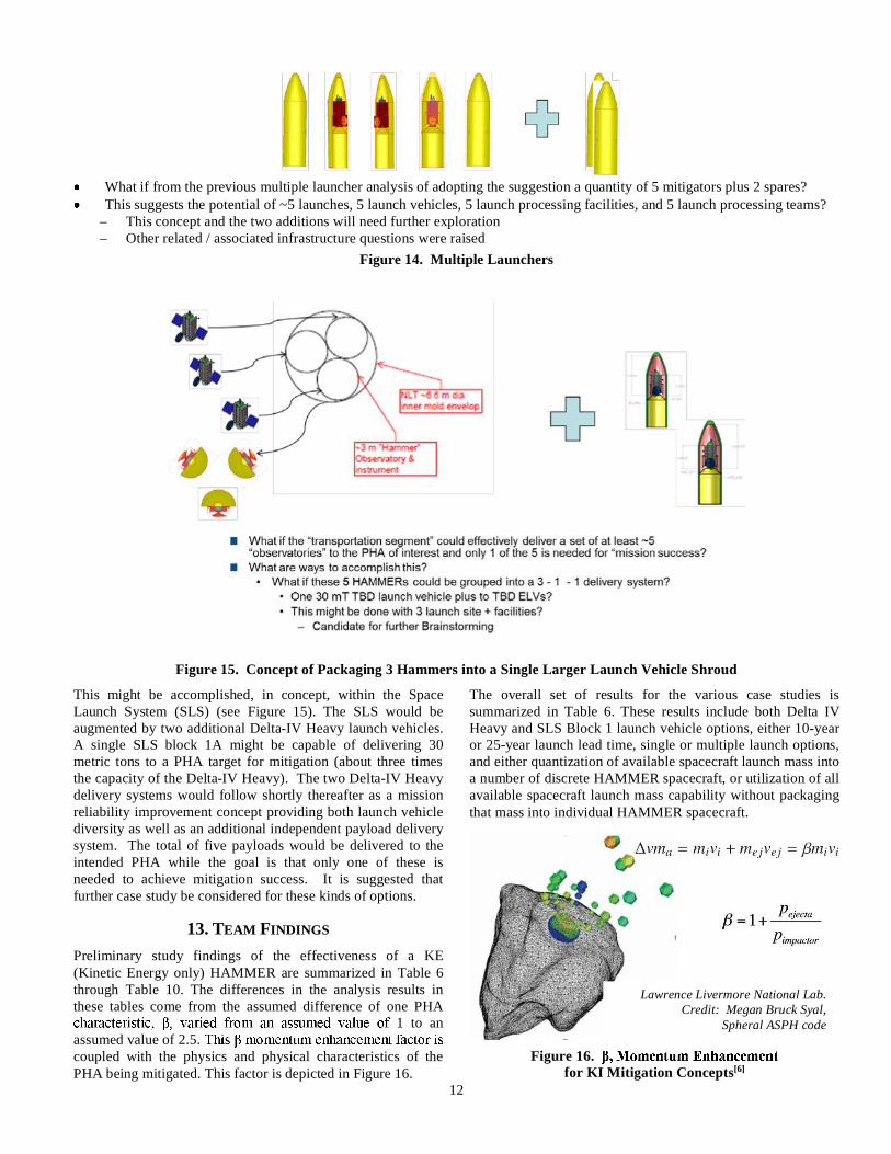
Figure 15. Concept of Packaging 3 Hammers into a Single Larger Launch Vehicle Shroud
This might be accomplished, in concept, within the SpaceLaunch System (SLS) (see Figure 15). The SLS would beaugmented by two additional Delta-IV Heavy launch vehicles.A single SLS block 1A might be capable of delivering 30metric tons to a PHA target for mitigation (about three timesthe capacity of the Delta-IV Heavy). The two Delta-IV Heavydelivery systems would follow shortly thereafter as a missionreliability improvement concept providing both launch vehiclediversity as well as an additional independent payload deliverysystem. The total of five payloads would be delivered to theintended PHA while the goal is that only one of these isneeded to achieve mitigation success. It is suggested thatfurther case study be considered for these kinds of options.
13. TEAM FINDINGS
Preliminary study findings of the effectiveness of a KE(Kinetic Energy only) HAMMER are summarized in Table 6through Table 10. The differences in the analysis results inthese tables come from the assumed difference of one PHA
1 to anassumed value of 2.5.coupled with the physics and physical characteristics of thePHA being mitigated. This factor is depicted in Figure 16.
The overall set of results for the various case studies issummarized in Table 6. These results include both Delta IVHeavy and SLS Block 1 launch vehicle options, either 10-yearor 25-year launch lead time, single or multiple launch options,and either quantization of available spacecraft launch mass intoa number of discrete HAMMER spacecraft, or utilization of allavailable spacecraft launch mass capability without packagingthat mass into individual HAMMER spacecraft.
Figure 16.for KI Mitigation Concepts[6]
Lawrence Livermore National Lab.Credit: Megan Bruck Syal,
Spheral ASPH code
13
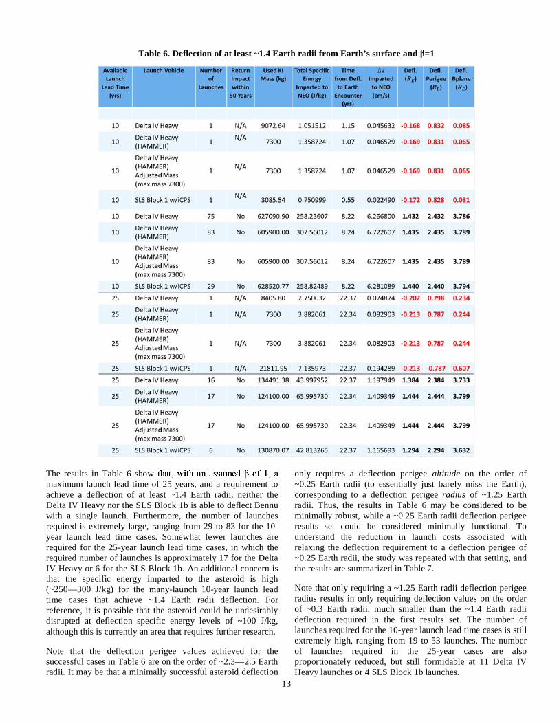
Table 6. Deflection of at least ~1.4 Earth radii from Earth’s surface and =1
The results in Table 6 showmaximum launch lead time of 25 years, and a requirement toachieve a deflection of at least ~1.4 Earth radii, neither theDelta IV Heavy nor the SLS Block 1b is able to deflect Bennuwith a single launch. Furthermore, the number of launchesrequired is extremely large, ranging from 29 to 83 for the 10-year launch lead time cases. Somewhat fewer launches arerequired for the 25-year launch lead time cases, in which therequired number of launches is approximately 17 for the DeltaIV Heavy or 6 for the SLS Block 1b. An additional concern isthat the specific energy imparted to the asteroid is high(~250—300 J/kg) for the many-launch 10-year launch leadtime cases that achieve ~1.4 Earth radii deflection. Forreference, it is possible that the asteroid could be undesirablydisrupted at deflection specific energy levels of ~100 J/kg,although this is currently an area that requires further research.
Note that the deflection perigee values achieved for thesuccessful cases in Table 6 are on the order of ~2.3—2.5 Earthradii. It may be that a minimally successful asteroid deflection
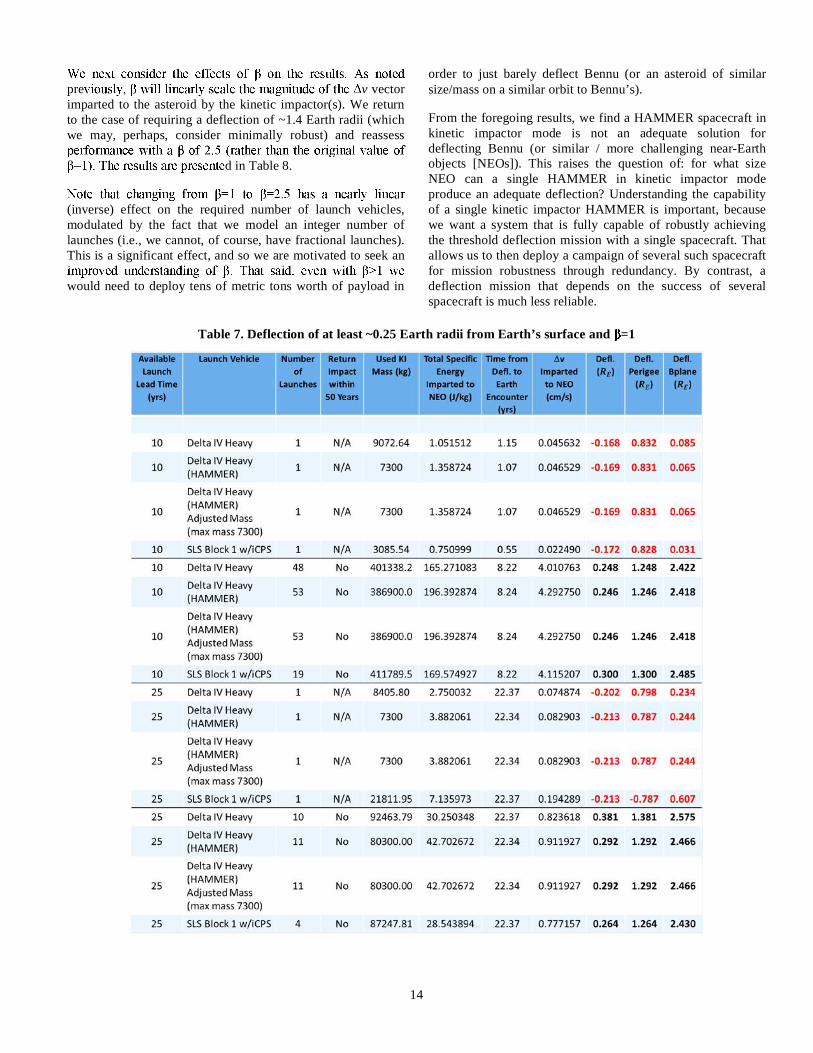
only requires a deflection perigee altitude on the order of~0.25 Earth radii (to essentially just barely miss the Earth),corresponding to a deflection perigee radius of ~1.25 Earthradii. Thus, the results in Table 6 may be considered to beminimally robust, while a ~0.25 Earth radii deflection perigeeresults set could be considered minimally functional. Tounderstand the reduction in launch costs associated withrelaxing the deflection requirement to a deflection perigee of~0.25 Earth radii, the study was repeated with that setting, andthe results are summarized in Table 7.
Note that only requiring a ~1.25 Earth radii deflection perigeeradius results in only requiring deflection values on the orderof ~0.3 Earth radii, much smaller than the ~1.4 Earth radiideflection required in the first results set. The number oflaunches required for the 10-year launch lead time cases is stillextremely high, ranging from 19 to 53 launches. The numberof launches required in the 25-year cases are alsoproportionately reduced, but still formidable at 11 Delta IVHeavy launches or 4 SLS Block 1b launches.
14
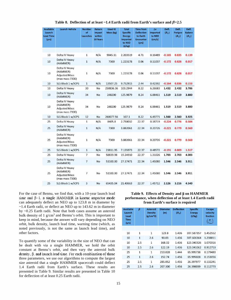
pre v vectorimparted to the asteroid by the kinetic impactor(s). We returnto the case of requiring a deflection of ~1.4 Earth radii (whichwe may, perhaps, consider minimally robust) and reassess
d in Table 8.
(inverse) effect on the required number of launch vehicles,modulated by the fact that we model an integer number oflaunches (i.e., we cannot, of course, have fractional launches).This is a significant effect, and so we are motivated to seek an
would need to deploy tens of metric tons worth of payload in
order to just barely deflect Bennu (or an asteroid of similarsize/mass on a similar orbit to Bennu’s).
From the foregoing results, we find a HAMMER spacecraft inkinetic impactor mode is not an adequate solution fordeflecting Bennu (or similar / more challenging near-Earthobjects [NEOs]). This raises the question of: for what sizeNEO can a single HAMMER in kinetic impactor modeproduce an adequate deflection? Understanding the capabilityof a single kinetic impactor HAMMER is important, becausewe want a system that is fully capable of robustly achievingthe threshold deflection mission with a single spacecraft. Thatallows us to then deploy a campaign of several such spacecraftfor mission robustness through redundancy. By contrast, adeflection mission that depends on the success of severalspacecraft is much less reliable.
Table 7. Deflection of at least ~0.25 Earth radii from Earth’s surface and =1
15
Table 8. Deflection of at least ~1.4 Earth radii from Earth’s surface and =2.5
For the case of Bennu, we find that, with a 10-year launch lead
can adequately deflect an NEO up to 123.8 m in diameter by~1.4 Earth radii, or deflect an NEO up to 143.62 m in diameterby ~0.25 Earth radii. Note that both cases assume an asteroidbulk density of 1 g/cm3 and Bennu’s orbit. This is important tokeep in mind, because the answer will vary depending on NEOorbit, bulk density, launch lead time, warning time (which, asnoted previously, is not the same as launch lead time), andother factors.
To quantify some of the variability in the size of NEO that canbe dealt with via a single HAMMER, we hold the orbitconstant at Bennu’s orbit, and then vary the asteroid bulk
three parameters, we use our algorithms to compute the largestsize asteroid that a single HAMMER spacecraft could deflect1.4 Earth radii from Earth’s surface. These results arepresented in Table 9. Similar results are presented in Table 10for deflection of at least 0.25 Earth radii.
Table 9. Effects of Density and on HAMMERperformance, when deflection of at least 1.4 Earth radii
from Earth’s surface is required
16
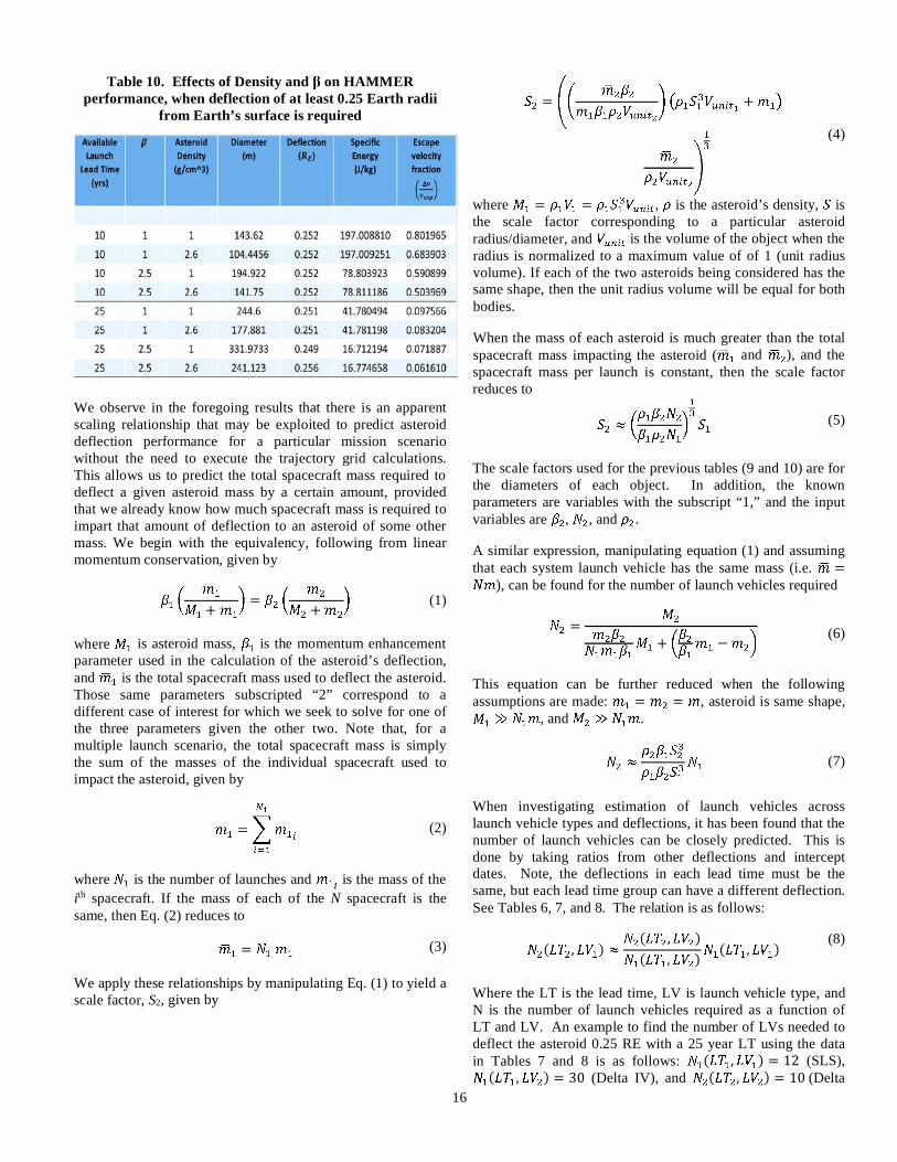
Table 10. Effects of Density and on HAMMERperformance, when deflection of at least 0.25 Earth radii
from Earth’s surface is required
We observe in the foregoing results that there is an apparentscaling relationship that may be exploited to predict asteroiddeflection performance for a particular mission scenariowithout the need to execute the trajectory grid calculations.This allows us to predict the total spacecraft mass required todeflect a given asteroid mass by a certain amount, providedthat we already know how much spacecraft mass is required toimpart that amount of deflection to an asteroid of some othermass. We begin with the equivalency, following from linearmomentum conservation, given by
+
=
+
(1)
where is asteroid mass, is the momentum enhancementparameter used in the calculation of the asteroid’s deflection,and is the total spacecraft mass used to deflect the asteroid.Those same parameters subscripted “2” correspond to adifferent case of interest for which we seek to solve for one ofthe three parameters given the other two. Note that, for amultiple launch scenario, the total spacecraft mass is simplythe sum of the masses of the individual spacecraft used toimpact the asteroid, given by
= (2)
where is the number of launches and is the mass of theith spacecraft. If the mass of each of the N spacecraft is thesame, then Eq. (2) reduces to
= (3)
We apply these relationships by manipulating Eq. (1) to yield ascale factor, S2, given by
=
+
(4)
where = = , is the asteroid’s density, isthe scale factor corresponding to a particular asteroidradius/diameter, and is the volume of the object when theradius is normalized to a maximum value of of 1 (unit radiusvolume). If each of the two asteroids being considered has thesame shape, then the unit radius volume will be equal for bothbodies.
When the mass of each asteroid is much greater than the totalspacecraft mass impacting the asteroid ( and ), and thespacecraft mass per launch is constant, then the scale factorreduces to
(5)
The scale factors used for the previous tables (9 and 10) are forthe diameters of each object. In addition, the knownparameters are variables with the subscript “1,” and the inputvariables are , , and .
A similar expression, manipulating equation (1) and assumingthat each system launch vehicle has the same mass (i.e. =
), can be found for the number of launch vehicles required
=
+
(6)
This equation can be further reduced when the followingassumptions are made: = = , asteroid is same shape,
, and .
(7)
When investigating estimation of launch vehicles acrosslaunch vehicle types and deflections, it has been found that thenumber of launch vehicles can be closely predicted. This isdone by taking ratios from other deflections and interceptdates. Note, the deflections in each lead time must be thesame, but each lead time group can have a different deflection.See Tables 6, 7, and 8. The relation is as follows:
( , )
( , )
( , )
( , )
(8)
Where the LT is the lead time, LV is launch vehicle type, andN is the number of launch vehicles required as a function ofLT and LV. An example to find the number of LVs needed todeflect the asteroid 0.25 RE with a 25 year LT using the datain Tables 7 and 8 is as follows: ( , ) = 12 (SLS),
( , ) = 30 (Delta IV), and ( , ) = 10(Delta
17
IV). Inputting these values into equation 8 yields 4 (SLS),which is the number of Launch vehicles required for deflectingthe asteroid about 0.25 Earth radii with a LT of 25 years.However, further investigations must be conducted to explorethe reliability of launch vehicle estimation when intercept datesgreatly vary in the same lead time.
14. SUMMARY
The HAMMER in kinetic impactor (KI) mode is clearlynot an adequate solution for deflecting Bennu (or similar/ more challenging NEOs).
decrease the required number of launches for kineticimpact deflection.
hysics will likelydictate deploying tens of metric tons worth of spacecraftin order to just barely alter the Bennu trajectory. Thisstudy utilized both the largest vendor available launchvehicle, the Delta IV Heavy, as well as the projectedcapabilities of the future NASA SLS version 1b. Theability to use other less capable launch vehicles is highlyunlikely.
Additionally, the ability to deliver the coordinatedquantity and coordinated simultaneity of theseHAMMERs would be unprecedented within the currentlyexisting national launch system infrastructure.
Use of international infrastructure of this magnitude wasbeyond this current case study.
Removing the constraints on minimum/maximumdistance to the Sun resulted in marginal improvements todeflection performance with a closest approach to the Sunof 0.4 – 0.6 AU.
Removing/loosening the other constraints (Declination ofthe Launch Asymptote [DLA], phase angle, Sun-Spacecraft-Earth [SSE] angle, maximum flight time, etc.)did not lead to notable deflection performanceimprovements (some did lead to an increase in thenumber of launch opportunities).
However, the above outcomes are particular to Bennu’sorbit; the situation will vary depending on the particularNEO orbit.
A single HAMMER in kinetic impactor mode is probablydiameter (with bulk
density of 1g/cm3 and Bennu’s orbit) with a 10-yearlaunch lead time. This mitigation approach will varydepending on NEO orbit, bulk density, and launch leadtime, and warning time (which is different than launchlead time).
It became clear from this case study that the use ofmultiple HAMMERs would need to be part of the toplevel concept formulation and trade space along withfuture work and analysis into the PHA physicalcharacteristics, payload complement within HAMMER(mass centroid detectors, terminal guidance systems,longer range detection and guidance, telemetry andcommunications, etc.).
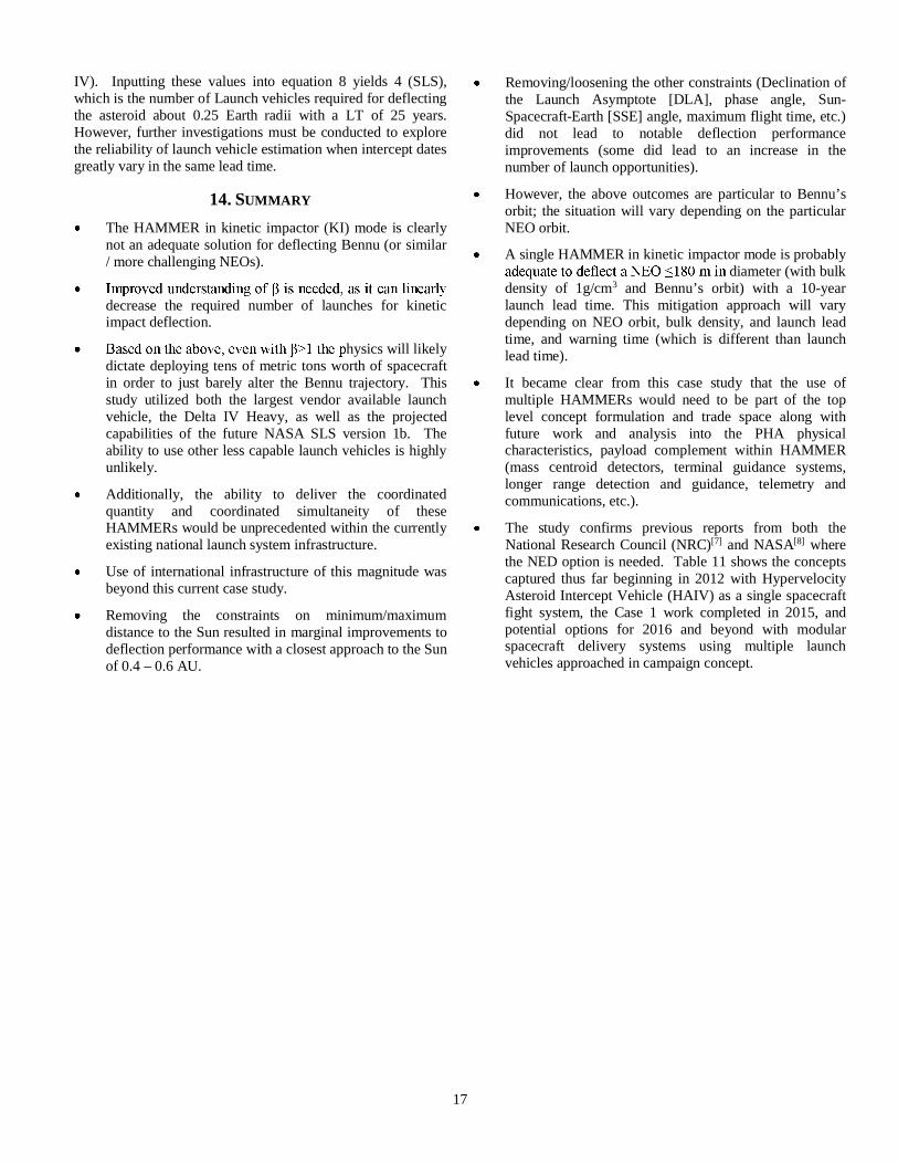
The study confirms previous reports from both theNational Research Council (NRC)[7] and NASA[8] wherethe NED option is needed. Table 11 shows the conceptscaptured thus far beginning in 2012 with HypervelocityAsteroid Intercept Vehicle (HAIV) as a single spacecraftfight system, the Case 1 work completed in 2015, andpotential options for 2016 and beyond with modularspacecraft delivery systems using multiple launchvehicles approached in campaign concept.
18
Table 11. PHA Mitigation Cases and Options being Considered
Option
AHypervelocity
Asteroid InterceptVehicle (HAIV)
Impactor leads NED,Class B+ - 2012
BHypervelocity Asteroid MitigationMission of Emergency Response
(HAMMER) Kinetic Impactor & NEDcombination, Class A+ - 2016
(NEO Mitigation – Bennu)
C~QTY 5 to 7 “Modular
Observatories”HAMMER – 20xx?
DAIM / DART
(2 partmission);Didymos
encounter;kinetic
FOM /Rating+3, +1,0, -1, -3VG, G,Nutr,B, VB
AsteroidSize To be studied TBD
PotentialNEA size /masseffective-ness range
NEA 50m radius;62000 metric tons
NEA 500 m radius;6.2e7 metric tons To be studied
800m withmoon 150m;~1.7 gm /cm3
TBD
…
TBD
MissionTOF /duration
122 days NLT 900 days + TBD days / years storage;development ~ 5 yrs; total ~5.6 to 8 yrs
TOF range: 1.6 - ~3years; devel: ~ 5 years;total ~5.6 to 8 years(cascade / multi-threadw/ potential refresh)
~ 1 AU solardistance; 15months forDART (~425days)
TBD
EncounterMethod-ology
NED Kinetic Impactor or NED Campaign mode:3 - 1 - 1 AIM + DART TBD
ACKNOWLEDGEMENTS
This research was supported in part by an appointment to theNASA Mission Directorate Research Participation Program.This program is administered by the Oak Ridge Institute forScience and Education through an interagency agreementbetween the U.S. Department of Energy and NASA.
Additional contributors to this Case Study 1: Megan BruckSyal, Joseph Wasem, Galen R. Gisler.
REFERENCES
[1] KSC launch schedule:https://www.kennedyspacecenter.com/events.aspx orhttp://www.nasa.gov/press-release/nasa-s-osiris-rex-speeds-toward-asteroid-rendezvous
[2] NASA launch services:http://www.nasa.gov/directorates/heo/launch_services/index.html
[3] Office of Safety and Mission Assurance, NASA ProceduralRequirements, NPR 8705.4, Risk Classification for NASAPayloads (Updated w/change 3), Effective Date: 14 June2004, Expiration Date: 14 June 2018.
[4] Johnson-Roth, Gail, Mission Assurance Guidelines for A-DMission Risk Classes, Aerospace Report No. TOR-2011(8591)-21, Prepared for: Space and Missile Systems Center,Air Force Space Command, 483 N. Aviation Blvd., ElSegundo, CA 90245-2808, Contract No. FA8802-09-C-0001, 3 June 2011.
[5] Alberts, David S. (David Stephen), Understanding commandand control, DoD Command and Control Research Program,2006. ISBN 1-893723-17-8
[6] Bruck Syal, Megan, Planetary Defense at LLNL: How toProtect Earth from Hazardous Asteroids, 13 January 2016,Future In-Space Operations (FISO) LLNL-PRES-659183.
PT
TS S
19
[7] Space Studies Board, National Research Council, DefendingPlanet Earth: Near Earth Object Surveys and HazardMitigation Strategies, 2010.
[8] NASA HQ Office of Program Analysis and Evaluation,Near-Earth Object Survey and Deflection Study, 2006.
[9] Barbee, B. W., Wie, B., Steiner, M., and Getzandanner, K.,Conceptual Design of a Hypervelocity Asteroid InterceptVehicle (HAIV) Flight Validation Mission, AIAA-2013-4544, Chapter DOI:10.2514/6.2013-4544 (2013).
[10] Dearborn, David S. P., and Ferguson, Jim M., When anImpactor is Not Enough: The Realistic Nuclear Option forStandoff Deflection, Extended Abstract 4th IAA PlanetaryDefense Conference – PDC 2015 13-17 April 2015, Frascati,Roma, Italy, IAA-PDC-15-03-05.
[11] Janus, P., John, Homing, Guidance (A Tutorial Report)AD-756 973, Space and Missile Systems Organization, 10December 1964.
[12] Hawkins, M., Guo, Y., and Wie, B., Spacecraft GuidanceAlgorithms for Asteroid Intercept and Rendezvous Missions,International Journal of Aeronautical & Space Science, Vol.13 (2), pp. 154–169 (2012).
[13] Lyzhoft, J., Hawkins, M., and Wie, B., GPU-Based OpticalNavigation and Terminal Guidance Simulation of aHypervelocity Asteroid Intercept Vehicle, AIAA-2013-4966,AIAA Guidance, Navigation, and Control Conference,Boston, MA, August 19-22, 2013.
[14] Moran, Inanc and Altilar, Turgay, Three Plane Approachfor 3D True Proportional Navigation, AIAA Guidance,Navigation, and Control Conference, 2005.
[15] Hawkins, Matt, Pitz, Alan, Wie, Bong, and Gil-Fernandez,Jesus, Terminal-Phase Guidance and Control Analysis ofAsteroid Interceptors, AIAA Guidance, Navigation, andControl Conference, 2010.
[16] Barbee, Brent W., Wie, Bong, Steiner, Mark,Getzandanner, Kenneth, Conceptual design of a flightvalidation mission for a Hypervelocity Asteroid InterceptVehicle, Acta Astronautica, Volume 106, January–February2015, pp. 139-159, ISSN 0094-5765.
BIOGRAPHY
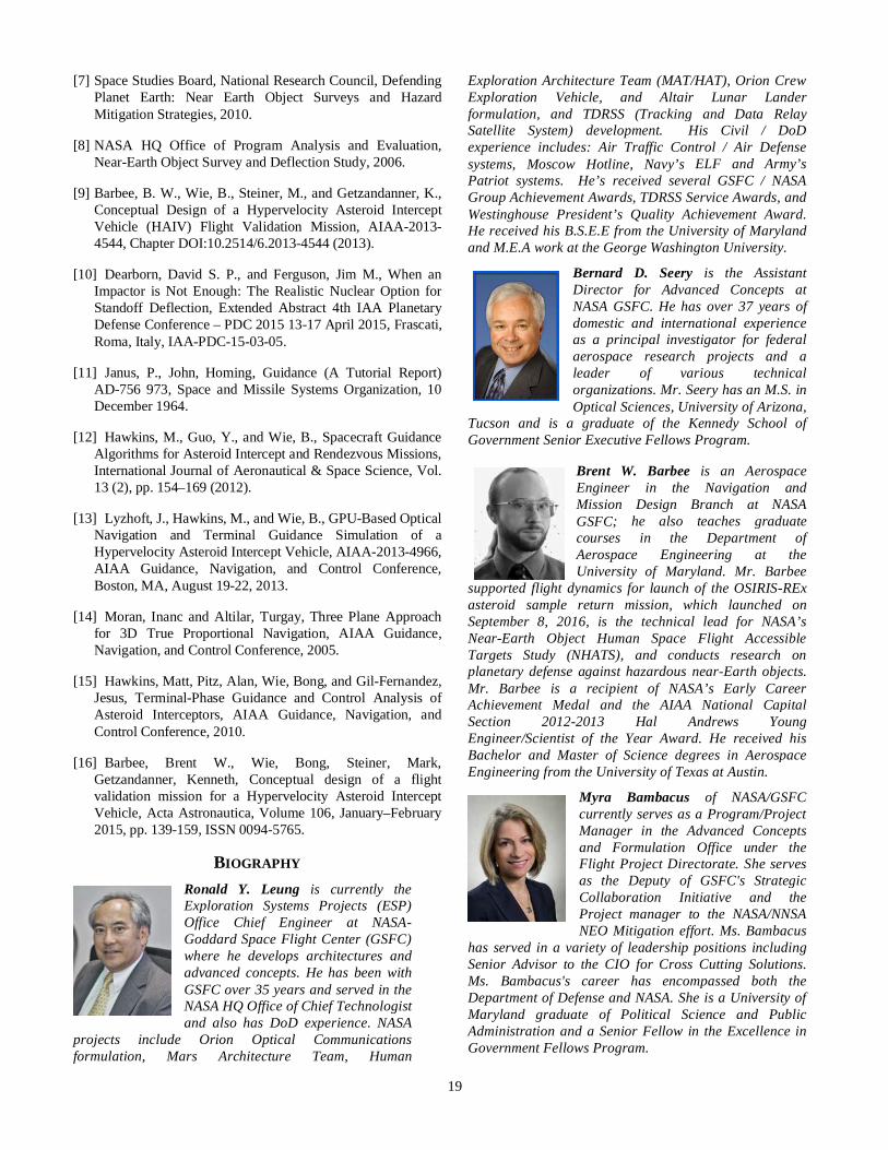
Ronald Y. Leung is currently theExploration Systems Projects (ESP)Office Chief Engineer at NASA-Goddard Space Flight Center (GSFC)where he develops architectures andadvanced concepts. He has been withGSFC over 35 years and served in theNASA HQ Office of Chief Technologistand also has DoD experience. NASA
projects include Orion Optical Communicationsformulation, Mars Architecture Team, Human
Exploration Architecture Team (MAT/HAT), Orion CrewExploration Vehicle, and Altair Lunar Landerformulation, and TDRSS (Tracking and Data RelaySatellite System) development. His Civil / DoDexperience includes: Air Traffic Control / Air Defensesystems, Moscow Hotline, Navy’s ELF and Army’sPatriot systems. He’s received several GSFC / NASAGroup Achievement Awards, TDRSS Service Awards, andWestinghouse President’s Quality Achievement Award.He received his B.S.E.E from the University of Marylandand M.E.A work at the George Washington University.
Bernard D. Seery is the AssistantDirector for Advanced Concepts atNASA GSFC. He has over 37 years ofdomestic and international experienceas a principal investigator for federalaerospace research projects and aleader of various technicalorganizations. Mr. Seery has an M.S. inOptical Sciences, University of Arizona,
Tucson and is a graduate of the Kennedy School ofGovernment Senior Executive Fellows Program.
Brent W. Barbee is an AerospaceEngineer in the Navigation andMission Design Branch at NASAGSFC; he also teaches graduatecourses in the Department ofAerospace Engineering at theUniversity of Maryland. Mr. Barbee
supported flight dynamics for launch of the OSIRIS-RExasteroid sample return mission, which launched onSeptember 8, 2016, is the technical lead for NASA’sNear-Earth Object Human Space Flight AccessibleTargets Study (NHATS), and conducts research onplanetary defense against hazardous near-Earth objects.Mr. Barbee is a recipient of NASA’s Early CareerAchievement Medal and the AIAA National CapitalSection 2012-2013 Hal Andrews YoungEngineer/Scientist of the Year Award. He received hisBachelor and Master of Science degrees in AerospaceEngineering from the University of Texas at Austin.
Myra Bambacus of NASA/GSFCcurrently serves as a Program/ProjectManager in the Advanced Conceptsand Formulation Office under theFlight Project Directorate. She servesas the Deputy of GSFC's StrategicCollaboration Initiative and theProject manager to the NASA/NNSANEO Mitigation effort. Ms. Bambacus
has served in a variety of leadership positions includingSenior Advisor to the CIO for Cross Cutting Solutions.Ms. Bambacus's career has encompassed both theDepartment of Defense and NASA. She is a University ofMaryland graduate of Political Science and PublicAdministration and a Senior Fellow in the Excellence inGovernment Fellows Program.
20
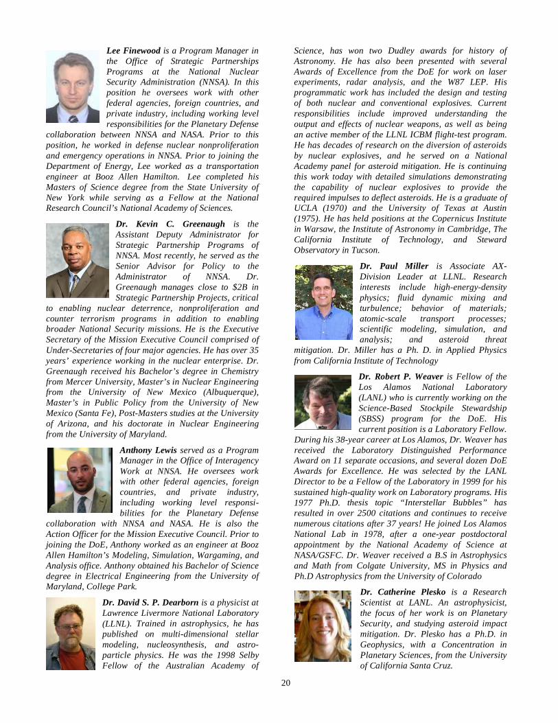
Lee Finewood is a Program Manager inthe Office of Strategic PartnershipsPrograms at the National NuclearSecurity Administration (NNSA). In thisposition he oversees work with otherfederal agencies, foreign countries, andprivate industry, including working levelresponsibilities for the Planetary Defense
collaboration between NNSA and NASA. Prior to thisposition, he worked in defense nuclear nonproliferationand emergency operations in NNSA. Prior to joining theDepartment of Energy, Lee worked as a transportationengineer at Booz Allen Hamilton. Lee completed hisMasters of Science degree from the State University ofNew York while serving as a Fellow at the NationalResearch Council’s National Academy of Sciences.
Dr. Kevin C. Greenaugh is theAssistant Deputy Administrator forStrategic Partnership Programs ofNNSA. Most recently, he served as theSenior Advisor for Policy to theAdministrator of NNSA. Dr.Greenaugh manages close to $2B inStrategic Partnership Projects, critical
to enabling nuclear deterrence, nonproliferation andcounter terrorism programs in addition to enablingbroader National Security missions. He is the ExecutiveSecretary of the Mission Executive Council comprised ofUnder-Secretaries of four major agencies. He has over 35years’ experience working in the nuclear enterprise. Dr.Greenaugh received his Bachelor’s degree in Chemistryfrom Mercer University, Master’s in Nuclear Engineeringfrom the University of New Mexico (Albuquerque),Master’s in Public Policy from the University of NewMexico (Santa Fe), Post-Masters studies at the Universityof Arizona, and his doctorate in Nuclear Engineeringfrom the University of Maryland.
Anthony Lewis served as a ProgramManager in the Office of InteragencyWork at NNSA. He oversees workwith other federal agencies, foreigncountries, and private industry,including working level responsi-bilities for the Planetary Defense
collaboration with NNSA and NASA. He is also theAction Officer for the Mission Executive Council. Prior tojoining the DoE, Anthony worked as an engineer at BoozAllen Hamilton’s Modeling, Simulation, Wargaming, andAnalysis office. Anthony obtained his Bachelor of Sciencedegree in Electrical Engineering from the University ofMaryland, College Park.
Dr. David S. P. Dearborn is a physicist atLawrence Livermore National Laboratory(LLNL). Trained in astrophysics, he haspublished on multi-dimensional stellarmodeling, nucleosynthesis, and astro-particle physics. He was the 1998 SelbyFellow of the Australian Academy of
Science, has won two Dudley awards for history ofAstronomy. He has also been presented with severalAwards of Excellence from the DoE for work on laserexperiments, radar analysis, and the W87 LEP. Hisprogrammatic work has included the design and testingof both nuclear and conventional explosives. Currentresponsibilities include improved understanding theoutput and effects of nuclear weapons, as well as beingan active member of the LLNL ICBM flight-test program.He has decades of research on the diversion of asteroidsby nuclear explosives, and he served on a NationalAcademy panel for asteroid mitigation. He is continuingthis work today with detailed simulations demonstratingthe capability of nuclear explosives to provide therequired impulses to deflect asteroids. He is a graduate ofUCLA (1970) and the University of Texas at Austin(1975). He has held positions at the Copernicus Institutein Warsaw, the Institute of Astronomy in Cambridge, TheCalifornia Institute of Technology, and StewardObservatory in Tucson.
Dr. Paul Miller is Associate AX-Division Leader at LLNL. Researchinterests include high-energy-densityphysics; fluid dynamic mixing andturbulence; behavior of materials;atomic-scale transport processes;scientific modeling, simulation, andanalysis; and asteroid threat
mitigation. Dr. Miller has a Ph. D. in Applied Physicsfrom California Institute of Technology
Dr. Robert P. Weaver is Fellow of theLos Alamos National Laboratory(LANL) who is currently working on theScience-Based Stockpile Stewardship(SBSS) program for the DoE. Hiscurrent position is a Laboratory Fellow.
During his 38-year career at Los Alamos, Dr. Weaver hasreceived the Laboratory Distinguished PerformanceAward on 11 separate occasions, and several dozen DoEAwards for Excellence. He was selected by the LANLDirector to be a Fellow of the Laboratory in 1999 for hissustained high-quality work on Laboratory programs. His1977 Ph.D. thesis topic “Interstellar Bubbles” hasresulted in over 2500 citations and continues to receivenumerous citations after 37 years! He joined Los AlamosNational Lab in 1978, after a one-year postdoctoralappointment by the National Academy of Science atNASA/GSFC. Dr. Weaver received a B.S in Astrophysicsand Math from Colgate University, MS in Physics andPh.D Astrophysics from the University of Colorado
Dr. Catherine Plesko is a ResearchScientist at LANL. An astrophysicist,the focus of her work is on PlanetarySecurity, and studying asteroid impactmitigation. Dr. Plesko has a Ph.D. inGeophysics, with a Concentration inPlanetary Sciences, from the Universityof California Santa Cruz.
Related Documents