ORIGINAL ARTICLE Multi-objective optimization of oil tanker design Apostolos Papanikolaou • George Zaraphonitis • Evangelos Boulougouris • Uwe Langbecker • Sven Matho • Pierre Sames Received: 12 November 2009 / Accepted: 26 June 2010 / Published online: 22 July 2010 Ó JASNAOE 2010 Abstract Parametric optimization was applied to a double-hull AFRAMAX tanker design in order to reduce oil-outflow probability and increase cargo carrying capac- ity, and the results are presented here. A multi-criteria optimization procedure was set up in modeFrontier Ò using the cargo volume, the mean oil-outflow parameter and the steel weight of the cargo block as the objective functions. Calculations are based on a parametric geometric model of the ship created in NAPA Ò , and on a structural model created in POSEIDON Ò . Integration of the above software packages leads to an automated optimization procedure that provides improved feedback to the designer regarding the trade-off between the various design parameters and optimization criteria involved. The results obtained suggest notable improvements in transport capacity and oil-outflow performance for known, well-established yard designs. The presented work derives from a joint industrial project between Germanischer Lloyd (GL) and the Ship Design Laboratory of the National Technical University of Athens (NTUA-SDL), which continues the work done and coor- dinated by NTUA-SDL within the SAFEDOR project on the same subject. Keywords Design optimization Risk-based design Genetic algorithms Multi-criteria decision making Accidental oil outflow 1 Background 1.1 Project outline Following a series of catastrophic single-hull tanker acci- dents, current IMO regulations (and long before that, US OPA90) state that double-hull tanker designs are the only acceptable solution for the safe carriage of oil in tanker ships. According to current MARPOL regulations, the tank arrangement of the cargo block of an oil tanker should be properly designed to provide adequate protection against accidental oil outflow, as expressed by the so-called mean outflow parameter. The present paper outlines the risk- based parametric optimization of a double-hull AFRA- MAX tanker in order to achieve innovative designs with increased cargo carrying capacities, reduced steel weights and improved environmental protection. The research presented here is based on the results of a joint industrial project between Germanischer Lloyd (GL) and the Ship Design Laboratory of the National Technical University of Athens (NTUA-SDL). This work is a further elaboration of an innovative risk-based oil tanker design procedure that was initiated in the framework of the EU project SAFEDOR. Building on the work presented earlier, the integration of the structural design software POSEIDON [1] into the multi-criteria optimization procedure allows the realistic estimation of the steel weight of the alternative designs, and the latest MARPOL regulations for accidental oil outflow (applicable to all newbuildings after 1 January 2010) have been implemented [2]. The fully automated optimiza- tion procedure developed here provides improved feedback to the designer regarding the trade-off between the various design parameters and the optimization criteria involved. The present study focuses on the optimization of the arrangement of the cargo area of an AFRAMAX class A. Papanikolaou (&) G. Zaraphonitis E. Boulougouris Ship Design Laboratory, School of Naval Architecture and Marine Engineering, National Technical University of Athens, Athens, Greece e-mail: [email protected] U. Langbecker S. Matho P. Sames Germanischer Lloyd AG, Hamburg, Germany 123 J Mar Sci Technol (2010) 15:359–373 DOI 10.1007/s00773-010-0097-7

Welcome message from author
This document is posted to help you gain knowledge. Please leave a comment to let me know what you think about it! Share it to your friends and learn new things together.
Transcript
ORIGINAL ARTICLE
Multi-objective optimization of oil tanker design
Apostolos Papanikolaou • George Zaraphonitis •
Evangelos Boulougouris • Uwe Langbecker •
Sven Matho • Pierre Sames
Received: 12 November 2009 / Accepted: 26 June 2010 / Published online: 22 July 2010
� JASNAOE 2010
Abstract Parametric optimization was applied to a
double-hull AFRAMAX tanker design in order to reduce
oil-outflow probability and increase cargo carrying capac-
ity, and the results are presented here. A multi-criteria
optimization procedure was set up in modeFrontier� using
the cargo volume, the mean oil-outflow parameter and the
steel weight of the cargo block as the objective functions.
Calculations are based on a parametric geometric model of
the ship created in NAPA�, and on a structural model
created in POSEIDON�. Integration of the above software
packages leads to an automated optimization procedure
that provides improved feedback to the designer regarding
the trade-off between the various design parameters and
optimization criteria involved. The results obtained suggest
notable improvements in transport capacity and oil-outflow
performance for known, well-established yard designs. The
presented work derives from a joint industrial project
between Germanischer Lloyd (GL) and the Ship Design
Laboratory of the National Technical University of Athens
(NTUA-SDL), which continues the work done and coor-
dinated by NTUA-SDL within the SAFEDOR project on
the same subject.
Keywords Design optimization � Risk-based design �Genetic algorithms � Multi-criteria decision making �Accidental oil outflow
1 Background
1.1 Project outline
Following a series of catastrophic single-hull tanker acci-
dents, current IMO regulations (and long before that, US
OPA90) state that double-hull tanker designs are the only
acceptable solution for the safe carriage of oil in tanker
ships. According to current MARPOL regulations, the tank
arrangement of the cargo block of an oil tanker should be
properly designed to provide adequate protection against
accidental oil outflow, as expressed by the so-called mean
outflow parameter. The present paper outlines the risk-
based parametric optimization of a double-hull AFRA-
MAX tanker in order to achieve innovative designs with
increased cargo carrying capacities, reduced steel weights
and improved environmental protection.
The research presented here is based on the results of a
joint industrial project between Germanischer Lloyd (GL)
and the Ship Design Laboratory of the National Technical
University of Athens (NTUA-SDL). This work is a further
elaboration of an innovative risk-based oil tanker design
procedure that was initiated in the framework of the EU
project SAFEDOR. Building on the work presented earlier,
the integration of the structural design software POSEIDON
[1] into the multi-criteria optimization procedure allows the
realistic estimation of the steel weight of the alternative
designs, and the latest MARPOL regulations for accidental oil
outflow (applicable to all newbuildings after 1 January 2010)
have been implemented [2]. The fully automated optimiza-
tion procedure developed here provides improved feedback to
the designer regarding the trade-off between the various
design parameters and the optimization criteria involved.
The present study focuses on the optimization of the
arrangement of the cargo area of an AFRAMAX class
A. Papanikolaou (&) � G. Zaraphonitis � E. Boulougouris
Ship Design Laboratory, School of Naval Architecture
and Marine Engineering, National Technical University
of Athens, Athens, Greece
e-mail: [email protected]
U. Langbecker � S. Matho � P. Sames
Germanischer Lloyd AG, Hamburg, Germany
123
J Mar Sci Technol (2010) 15:359–373
DOI 10.1007/s00773-010-0097-7
tanker, with the aim being to identify the best-performing
designs in terms of both reduced accidental oil outflow and
improved economic competitiveness. However, the pro-
posed methodology can be extended to include additional
objectives or design aspects, such as the ship’s hull form
and internal arrangements, and can be easily extended to
other oil tanker classes.
1.2 Reference design
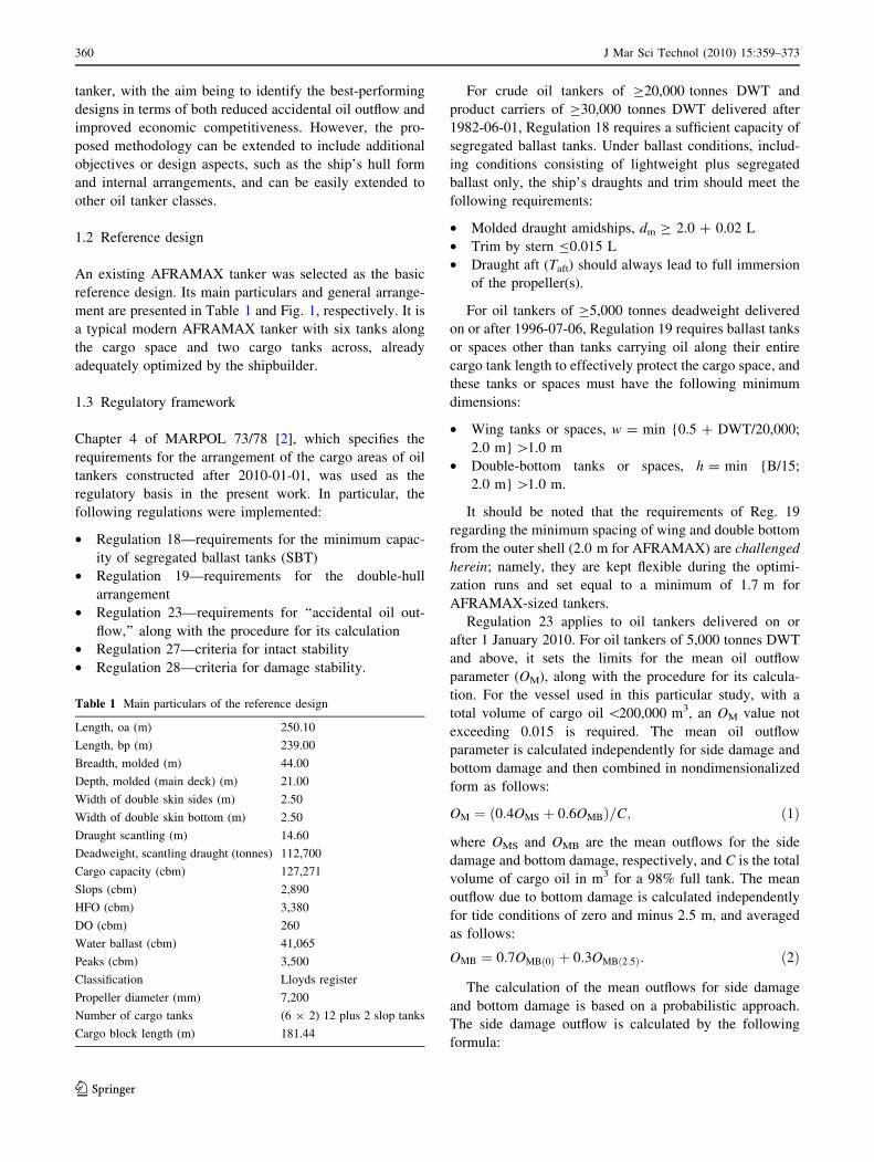
An existing AFRAMAX tanker was selected as the basic
reference design. Its main particulars and general arrange-
ment are presented in Table 1 and Fig. 1, respectively. It is
a typical modern AFRAMAX tanker with six tanks along
the cargo space and two cargo tanks across, already
adequately optimized by the shipbuilder.
1.3 Regulatory framework
Chapter 4 of MARPOL 73/78 [2], which specifies the
requirements for the arrangement of the cargo areas of oil
tankers constructed after 2010-01-01, was used as the
regulatory basis in the present work. In particular, the
following regulations were implemented:
• Regulation 18—requirements for the minimum capac-
ity of segregated ballast tanks (SBT)
• Regulation 19—requirements for the double-hull
arrangement
• Regulation 23—requirements for ‘‘accidental oil out-
flow,’’ along with the procedure for its calculation
• Regulation 27—criteria for intact stability
• Regulation 28—criteria for damage stability.
For crude oil tankers of C20,000 tonnes DWT and
product carriers of C30,000 tonnes DWT delivered after
1982-06-01, Regulation 18 requires a sufficient capacity of
segregated ballast tanks. Under ballast conditions, includ-
ing conditions consisting of lightweight plus segregated
ballast only, the ship’s draughts and trim should meet the
following requirements:
• Molded draught amidships, dm C 2.0 ? 0.02 L
• Trim by stern B0.015 L
• Draught aft (Taft) should always lead to full immersion
of the propeller(s).
For oil tankers of C5,000 tonnes deadweight delivered
on or after 1996-07-06, Regulation 19 requires ballast tanks
or spaces other than tanks carrying oil along their entire
cargo tank length to effectively protect the cargo space, and
these tanks or spaces must have the following minimum
dimensions:
• Wing tanks or spaces, w = min {0.5 ? DWT/20,000;
2.0 m} [1.0 m
• Double-bottom tanks or spaces, h = min {B/15;
2.0 m} [1.0 m.
It should be noted that the requirements of Reg. 19
regarding the minimum spacing of wing and double bottom
from the outer shell (2.0 m for AFRAMAX) are challenged
herein; namely, they are kept flexible during the optimi-
zation runs and set equal to a minimum of 1.7 m for
AFRAMAX-sized tankers.
Regulation 23 applies to oil tankers delivered on or
after 1 January 2010. For oil tankers of 5,000 tonnes DWT
and above, it sets the limits for the mean oil outflow
parameter (OM), along with the procedure for its calcula-
tion. For the vessel used in this particular study, with a
total volume of cargo oil \200,000 m3, an OM value not
exceeding 0.015 is required. The mean oil outflow
parameter is calculated independently for side damage and
bottom damage and then combined in nondimensionalized
form as follows:
OM ¼ 0:4OMS þ 0:6OMBð Þ=C; ð1Þ
where OMS and OMB are the mean outflows for the side
damage and bottom damage, respectively, and C is the total
volume of cargo oil in m3 for a 98% full tank. The mean
outflow due to bottom damage is calculated independently
for tide conditions of zero and minus 2.5 m, and averaged
as follows:
OMB ¼ 0:7OMBð0Þ þ 0:3OMBð2:5Þ: ð2Þ
The calculation of the mean outflows for side damage
and bottom damage is based on a probabilistic approach.
The side damage outflow is calculated by the following
formula:
Table 1 Main particulars of the reference design
Length, oa (m) 250.10
Length, bp (m) 239.00
Breadth, molded (m) 44.00
Depth, molded (main deck) (m) 21.00
Width of double skin sides (m) 2.50
Width of double skin bottom (m) 2.50
Draught scantling (m) 14.60
Deadweight, scantling draught (tonnes) 112,700
Cargo capacity (cbm) 127,271
Slops (cbm) 2,890
HFO (cbm) 3,380
DO (cbm) 260
Water ballast (cbm) 41,065
Peaks (cbm) 3,500
Classification Lloyds register
Propeller diameter (mm) 7,200
Number of cargo tanks (6 9 2) 12 plus 2 slop tanks
Cargo block length (m) 181.44
360 J Mar Sci Technol (2010) 15:359–373
123
OMS ¼ C3
Xn
1
PSðiÞOSðiÞ ðm3Þ; ð3Þ
where PS(i) is the probability of penetrating cargo tank
i through side damage, OS(i) is the corresponding outflow in
m3, while C3 is an appropriate coefficient. Accordingly, the
bottom damage outflow for either zero or minus 2.5 m tide
conditions is calculated by the following formula:
OMB ¼Xn
1
PBðiÞOBðiÞCDBðiÞ m3� �
: ð4Þ
In the above equation, CDB(i) accounts for the capture of
oil flowing out of a tank in the double bottom.
2 Design optimization
The main objective of this study was to improve the
accidental oil-outflow performance of the reference cargo
tank arrangement, while at the same time minimizing the
steel weight and maximizing the cargo capacity. Improving
the performance of a ship in terms of oil outflow, maxi-
mization of cargo capacity, and minimization of steel
weight are contradictory objectives; for example, the for-
mer requires an increased distance of the cargo space from
the outer shell, resulting in a reduction in cargo tank vol-
ume; also, a reduction in the mean outflow parameter can
be achieved with more subdivision, by decreasing the
average size of each cargo tank, and at the same time
increasing the steel weight (with a corresponding increase
in construction cost and reduction in payload). Therefore,
to optimally achieve these contradictory objectives, a for-
mal multi-objective optimization procedure was developed
and applied.
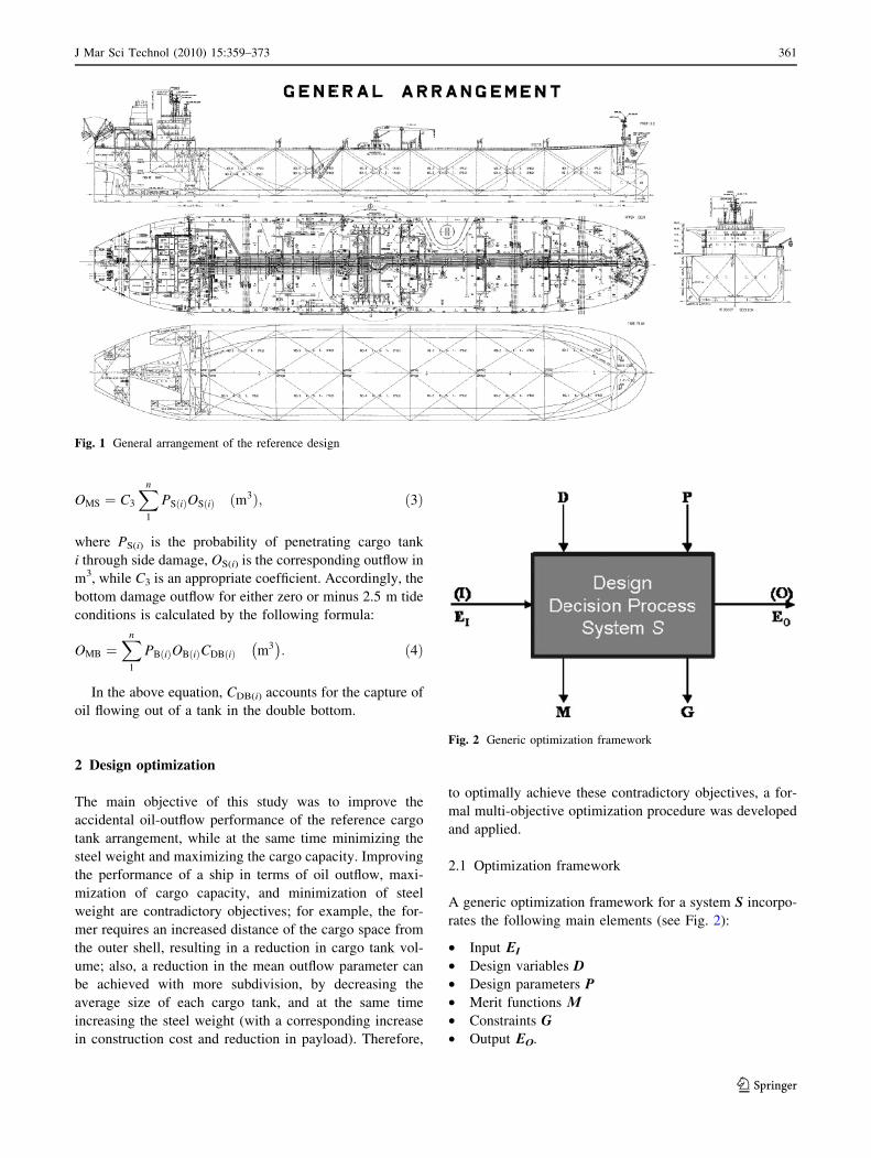
2.1 Optimization framework
A generic optimization framework for a system S incorpo-
rates the following main elements (see Fig. 2):
• Input EI
• Design variables D
• Design parameters P
• Merit functions L
• Constraints G
• Output EO.
Fig. 1 General arrangement of the reference design
Fig. 2 Generic optimization framework
J Mar Sci Technol (2010) 15:359–373 361
123
In the context of the present work, the difference
between the design parameters and the design variables is
that the former are kept constant during an optimization
study, while the latter are systematically varied to facilitate
the efficient exploration of the design space and to obtain
the optimum solution(s).
At the core of the developed optimization framework
there is a ‘‘parametric design tool,’’ developed within the
well-known ship design software NAPA� [3]. It consists of
a set of macros, developed in NAPA Basic, that facilitate
the fully automatic generation of the detailed layout of the
cargo block of a vessel, based on the values of a series of
design parameters and design variables. The design pool is
then created by systematically varying the design variables
while using predefined (user-selected) values for the design
parameters. This procedure evaluates the fulfillment of a
set of constraints, while a set of objectives are optimized at
the same time. This approach is holistic in nature and
allows the integration of as many objective functions and
constraints as needed for the design problem at hand [4].
The generic optimization framework developed by
NTUA-SDL was applied previously to a variety of prob-
lems, including the optimization of the watertight subdi-
vision of RoRo passenger ships [5], and the external
hullform optimization of high-speed ships [6]. This generic
procedure was adapted to the present optimization problem
by adding methods and the corresponding software tools
for the structural design of the steel structure of the ship
and for the probabilistic assessment of oil-outflow
performance.
2.2 Multi-objective optimization
Ship design is a typical optimization problem involving
multiple and frequently contradictory objective functions
and constraints. The easiest way to address such a multi-
objective problem would be to combine the objective
functions into one, assuming that the relative weights and
relationships between the objectives are known. In most
cases, however, these weights and relationships are
unknown, and there is little knowledge regarding the space
of feasible solutions. Hence, a truly multi-objective meth-
odology is required, leading to a set of ‘‘best designs;’’ in
other words, designs in which no one objective can be
improved without sacrificing the performance of another
objective. This set of ‘‘best designs’’ is known as the Pareto
set. It is represented graphically as the Pareto frontier.
For the present problem, multi-objective genetic algo-
rithms (GA) were selected as the most suitable optimiza-
tion method [7]. Genetic algorithms are stochastic,
nonlinear optimization methods that apply the principles of
biological evolution [8]. In particular, they utilize popula-
tions of solutions and apply selection, reproduction and
mutation methods, in contrast to more traditional optimi-
zation methods which use gradient information to move
between (successively better) points in solution space. This
makes them uniquely adaptive to multi-objective problems
such as finding Pareto frontiers.
With the Pareto set of nondominated designs in hand,
the designer can select an optimal solution according to
his preferences. This can be done in a number of ways,
such as:
• Using a utility function to rank the different designs
• Using scatter 2D and 3D diagrams to visually identify
the more attractive designs, comparing them on the
basis of the designer’s preferred criteria and experi-
ence-based selection
• Using other visual tools (parallel plots, histograms,
frequency plots, Student plots, etc.), and deciding
according to the designer’s experience.
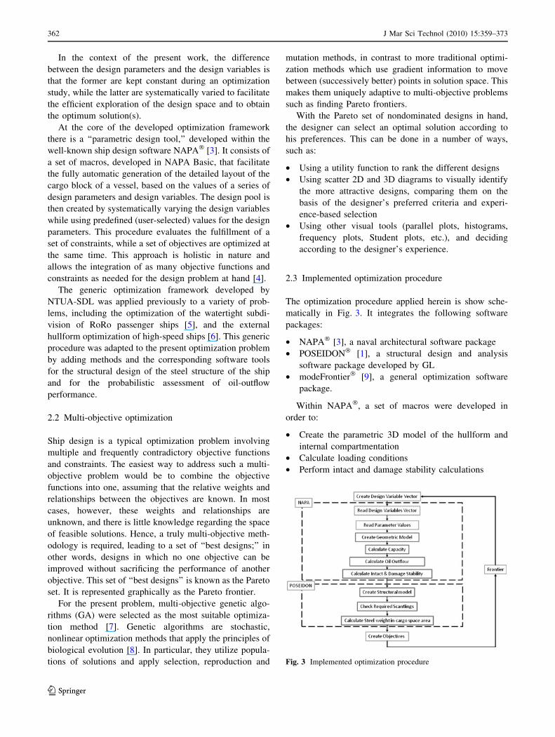
2.3 Implemented optimization procedure
The optimization procedure applied herein is show sche-
matically in Fig. 3. It integrates the following software
packages:
• NAPA� [3], a naval architectural software package
• POSEIDON� [1], a structural design and analysis
software package developed by GL
• modeFrontier� [9], a general optimization software
package.
Within NAPA�, a set of macros were developed in
order to:
• Create the parametric 3D model of the hullform and
internal compartmentation
• Calculate loading conditions
• Perform intact and damage stability calculations
Fig. 3 Implemented optimization procedure
362 J Mar Sci Technol (2010) 15:359–373
123
• Calculate the accidental oil outflow
• Prepare the necessary geometric data for the software
tools (POSEIDON) that perform the structural design.
POSEIDON� implements GL’s latest rules for classi-
fying a ship’s structure (Edition 2008, [10]). It allows the
automatic calculation of the scantlings for all structural
components based on rule requirements for the particular
vessel parameters, class notation, global bending, cargo
loads, and external sea pressure. Note that an additional
module was developed/implemented to create POSEI-
DON� models from a set of parameters. The same set of
parameters was used to define compartments in NAPA�
and to create the structural model in POSEIDON�, hence
ensuring consistency between the two models.
modeFRONTIER� is a general-purpose optimization
scheduler. It provides several optimization algorithms:
genetic algorithms, conjugate gradient method, quasi-
Newton method, sequential quadratic programming, sim-
plex, etc. The various optional algorithms can be com-
bined, such as genetic algorithms for global search and
another algorithm for local search (refinement). Software
modules running on different platforms can be integrated
via a network.
2.4 Design variables
The parametric definition of the layout and structural
arrangement of the cargo area of a ship requires a large
number of parameters, controlling the details of the
arrangement and of the various structural components. In
the present study, some of these parameters were kept
constant during each optimization run, while others were
treated as free variables and their values were selected (in a
predefined range) by the optimization scheduler. More
details on the design parameters employed and variables
are given in the following section describing the geometric
model.
2.5 Objectives
The following objectives were used:
• Maximization of the cargo capacity
• Minimization of the accidental oil-outflow parameter
according to MARPOL Annex I Regulation 23
• Minimization of the structural steel weight in the cargo
area while fulfilling the requirements of GL rules for
the construction of double-hull oil tankers (non-CSR).1
2.6 Constraints
The following constraints were employed:
• MARPOL Regulation 18 for mean draft, trim, propeller
immersion, etc.
• MARPOL Regulation 23, except for the minimum
spacing of the wings and double bottom, which was set
here for AFRAMAX tankers equal to 1.7 m2
• MARPOL Regulation 27—requirements for intact
stability
• MARPOL Regulation 28—requirements for damage
stability.
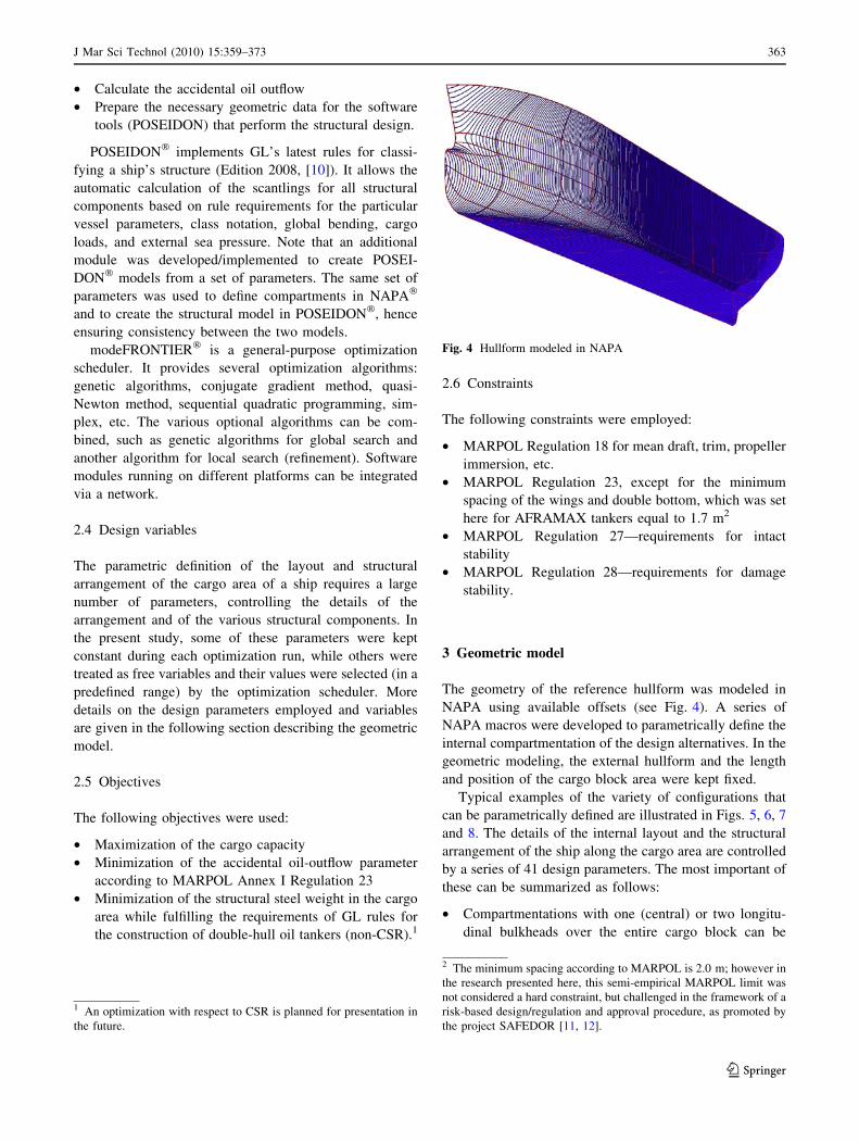
3 Geometric model
The geometry of the reference hullform was modeled in
NAPA using available offsets (see Fig. 4). A series of
NAPA macros were developed to parametrically define the
internal compartmentation of the design alternatives. In the
geometric modeling, the external hullform and the length
and position of the cargo block area were kept fixed.
Typical examples of the variety of configurations that
can be parametrically defined are illustrated in Figs. 5, 6, 7
and 8. The details of the internal layout and the structural
arrangement of the ship along the cargo area are controlled
by a series of 41 design parameters. The most important of
these can be summarized as follows:
• Compartmentations with one (central) or two longitu-
dinal bulkheads over the entire cargo block can be
Fig. 4 Hullform modeled in NAPA
1 An optimization with respect to CSR is planned for presentation in
the future.
2 The minimum spacing according to MARPOL is 2.0 m; however in
the research presented here, this semi-empirical MARPOL limit was
not considered a hard constraint, but challenged in the framework of a
risk-based design/regulation and approval procedure, as promoted by
the project SAFEDOR [11, 12].
J Mar Sci Technol (2010) 15:359–373 363
123
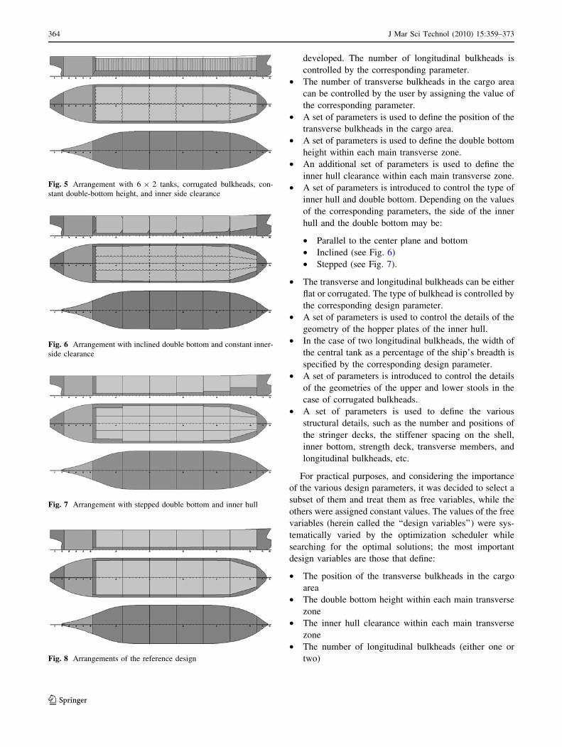
developed. The number of longitudinal bulkheads is
controlled by the corresponding parameter.
• The number of transverse bulkheads in the cargo area
can be controlled by the user by assigning the value of
the corresponding parameter.
• A set of parameters is used to define the position of the
transverse bulkheads in the cargo area.
• A set of parameters is used to define the double bottom
height within each main transverse zone.
• An additional set of parameters is used to define the
inner hull clearance within each main transverse zone.
• A set of parameters is introduced to control the type of
inner hull and double bottom. Depending on the values
of the corresponding parameters, the side of the inner
hull and the double bottom may be:
• Parallel to the center plane and bottom
• Inclined (see Fig. 6)
• Stepped (see Fig. 7).
• The transverse and longitudinal bulkheads can be either
flat or corrugated. The type of bulkhead is controlled by
the corresponding design parameter.
• A set of parameters is used to control the details of the
geometry of the hopper plates of the inner hull.
• In the case of two longitudinal bulkheads, the width of
the central tank as a percentage of the ship’s breadth is
specified by the corresponding design parameter.
• A set of parameters is introduced to control the details
of the geometries of the upper and lower stools in the
case of corrugated bulkheads.
• A set of parameters is used to define the various
structural details, such as the number and positions of
the stringer decks, the stiffener spacing on the shell,
inner bottom, strength deck, transverse members, and
longitudinal bulkheads, etc.
For practical purposes, and considering the importance
of the various design parameters, it was decided to select a
subset of them and treat them as free variables, while the
others were assigned constant values. The values of the free
variables (herein called the ‘‘design variables’’) were sys-
tematically varied by the optimization scheduler while
searching for the optimal solutions; the most important
design variables are those that define:
• The position of the transverse bulkheads in the cargo
area
• The double bottom height within each main transverse
zone
• The inner hull clearance within each main transverse
zone
• The number of longitudinal bulkheads (either one or
two)
Fig. 5 Arrangement with 6 9 2 tanks, corrugated bulkheads, con-
stant double-bottom height, and inner side clearance
Fig. 6 Arrangement with inclined double bottom and constant inner-
side clearance
Fig. 7 Arrangement with stepped double bottom and inner hull
Fig. 8 Arrangements of the reference design
364 J Mar Sci Technol (2010) 15:359–373
123
• The width of the central tank as a percentage of the
ship’s breadth in the case of two longitudinal bulkheads
• The distance between transverse frames
• The distance between longitudinal stiffeners
• The inclination of the hopper plate that connects the
double bottom with the inner hull.
For example, for the typical case of a vessel with 6 9 2
or 6 9 3 tanks (i.e., with five transverse bulkheads inside
the cargo block and one or two longitudinal bulkheads),
this results in a total of 26–27 design variables.
4 Structural model
4.1 Typical AFRAMAX structure
AFRAMAX-sized oil tankers (80,000 tonnes DWT to
119,999 tonnes DWT) are commonly longitudinally
framed ships over the full length of the cargo block. They
usually include a large number of continuous, longitudinal,
closely spaced stiffeners and a small number of web frames
that are spaced more sparsely. A centerline bulkhead sep-
arates across the two cargo tanks. A hopper sloping plate at
the lower part connects the longitudinal girder with the first
stringer and provides strength and rigidity at the double-
bottom wing space interface. There are typically three
stringers in the wing space that connect the inner hull with
the side shell. Floors, vertical webs in the wing tanks and at
the longitudinal bulkheads, and deck transverses are
arranged at every web frame.
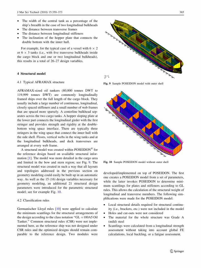
A structural model was created within POSEIDON� for
the reference design based on available structural infor-
mation [1]. The model was more detailed in the cargo area
and limited in the bow and stern region; see Fig. 9. The
structural model was created in such a way that all layouts
and topologies addressed in the previous section on
geometry modeling could easily be built up in an automatic
way. As well as the 15 (16) design variables necessary for
geometry modeling, an additional 21 structural design
parameters were introduced for the parametric structural
model; see for example Fig. 10.
4.2 Classification rules
Germanischer Lloyd rules [10] were applied to calculate
the minimum scantlings for the structural arrangements of
the design according to the class notation ‘‘GL ?100A5 Oil
Tanker.’’ Common structural rules (CSR) were not imple-
mented here, as the reference ship was not designed under
CSR rules and the optimized designs should remain com-
parable to the reference design. Two modules were
developed/implemented on top of POSEIDON. The first
one creates a POSEIDON model from a set of parameters,
while the latter invokes POSEIDON to determine mini-
mum scantlings for plates and stiffeners according to GL
rules. This allows the calculation of the structural weight of
longitudinal and transverse members. The following sim-
plifications were made for the POSEIDON model:
• Local structural details required for structural continu-
ity (i.e., brackets, etc.) were not included in the model
• Holes and cut-outs were not considered
• The material for the whole structure was Grade A
(mild) steel
• Scantlings were calculated from a longitudinal strength
assessment without taking into account global FE
calculations, local buckling, or a fatigue assessment.
Fig. 9 Sample POSEIDON model with outer shell
Fig. 10 Sample POSEIDON model without outer shell
J Mar Sci Technol (2010) 15:359–373 365
123
5 Case studies
5.1 Alternative configurations
Five different configurations were considered, with six or
seven tanks in the longitudinal direction, two or three tanks
in the transverse direction, and flat or corrugated bulk-
heads. The five different combinations are summarized in
Table 2. A total of 21,500 designs were examined in the
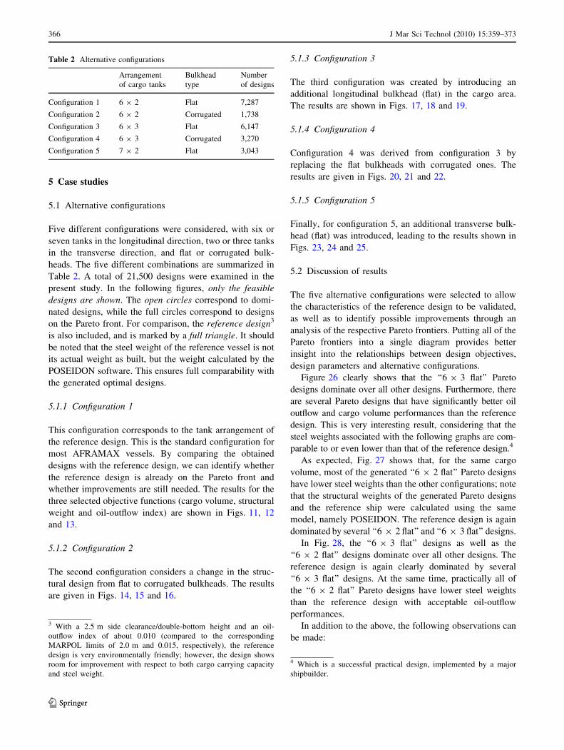
present study. In the following figures, only the feasible
designs are shown. The open circles correspond to domi-
nated designs, while the full circles correspond to designs
on the Pareto front. For comparison, the reference design3
is also included, and is marked by a full triangle. It should
be noted that the steel weight of the reference vessel is not
its actual weight as built, but the weight calculated by the
POSEIDON software. This ensures full comparability with
the generated optimal designs.
5.1.1 Configuration 1
This configuration corresponds to the tank arrangement of
the reference design. This is the standard configuration for
most AFRAMAX vessels. By comparing the obtained
designs with the reference design, we can identify whether
the reference design is already on the Pareto front and
whether improvements are still needed. The results for the
three selected objective functions (cargo volume, structural
weight and oil-outflow index) are shown in Figs. 11, 12
and 13.
5.1.2 Configuration 2
The second configuration considers a change in the struc-
tural design from flat to corrugated bulkheads. The results
are given in Figs. 14, 15 and 16.
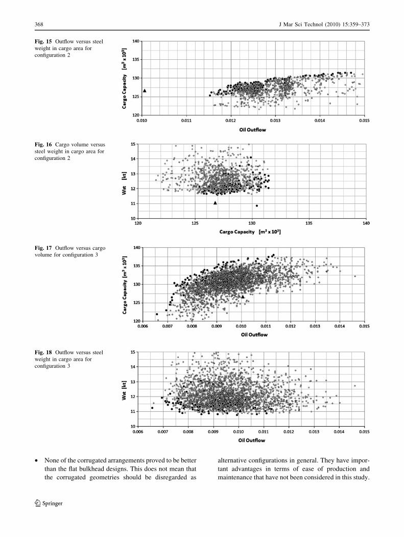
5.1.3 Configuration 3
The third configuration was created by introducing an
additional longitudinal bulkhead (flat) in the cargo area.
The results are shown in Figs. 17, 18 and 19.
5.1.4 Configuration 4
Configuration 4 was derived from configuration 3 by
replacing the flat bulkheads with corrugated ones. The
results are given in Figs. 20, 21 and 22.
5.1.5 Configuration 5
Finally, for configuration 5, an additional transverse bulk-
head (flat) was introduced, leading to the results shown in
Figs. 23, 24 and 25.
5.2 Discussion of results
The five alternative configurations were selected to allow
the characteristics of the reference design to be validated,
as well as to identify possible improvements through an
analysis of the respective Pareto frontiers. Putting all of the
Pareto frontiers into a single diagram provides better
insight into the relationships between design objectives,
design parameters and alternative configurations.
Figure 26 clearly shows that the ‘‘6 9 3 flat’’ Pareto
designs dominate over all other designs. Furthermore, there
are several Pareto designs that have significantly better oil
outflow and cargo volume performances than the reference
design. This is very interesting result, considering that the
steel weights associated with the following graphs are com-
parable to or even lower than that of the reference design.4
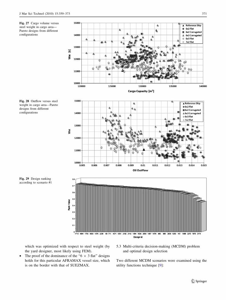
As expected, Fig. 27 shows that, for the same cargo
volume, most of the generated ‘‘6 9 2 flat’’ Pareto designs
have lower steel weights than the other configurations; note
that the structural weights of the generated Pareto designs
and the reference ship were calculated using the same
model, namely POSEIDON. The reference design is again
dominated by several ‘‘6 9 2 flat’’ and ‘‘6 9 3 flat’’ designs.
In Fig. 28, the ‘‘6 9 3 flat’’ designs as well as the
‘‘6 9 2 flat’’ designs dominate over all other designs. The
reference design is again clearly dominated by several
‘‘6 9 3 flat’’ designs. At the same time, practically all of
the ‘‘6 9 2 flat’’ Pareto designs have lower steel weights
than the reference design with acceptable oil-outflow
performances.
In addition to the above, the following observations can
be made:
Table 2 Alternative configurations
Arrangement
of cargo tanks
Bulkhead
type
Number
of designs
Configuration 1 6 9 2 Flat 7,287
Configuration 2 6 9 2 Corrugated 1,738
Configuration 3 6 9 3 Flat 6,147
Configuration 4 6 9 3 Corrugated 3,270
Configuration 5 7 9 2 Flat 3,043
3 With a 2.5 m side clearance/double-bottom height and an oil-
outflow index of about 0.010 (compared to the corresponding
MARPOL limits of 2.0 m and 0.015, respectively), the reference
design is very environmentally friendly; however, the design shows
room for improvement with respect to both cargo carrying capacity
and steel weight.
4 Which is a successful practical design, implemented by a major
shipbuilder.
366 J Mar Sci Technol (2010) 15:359–373
123
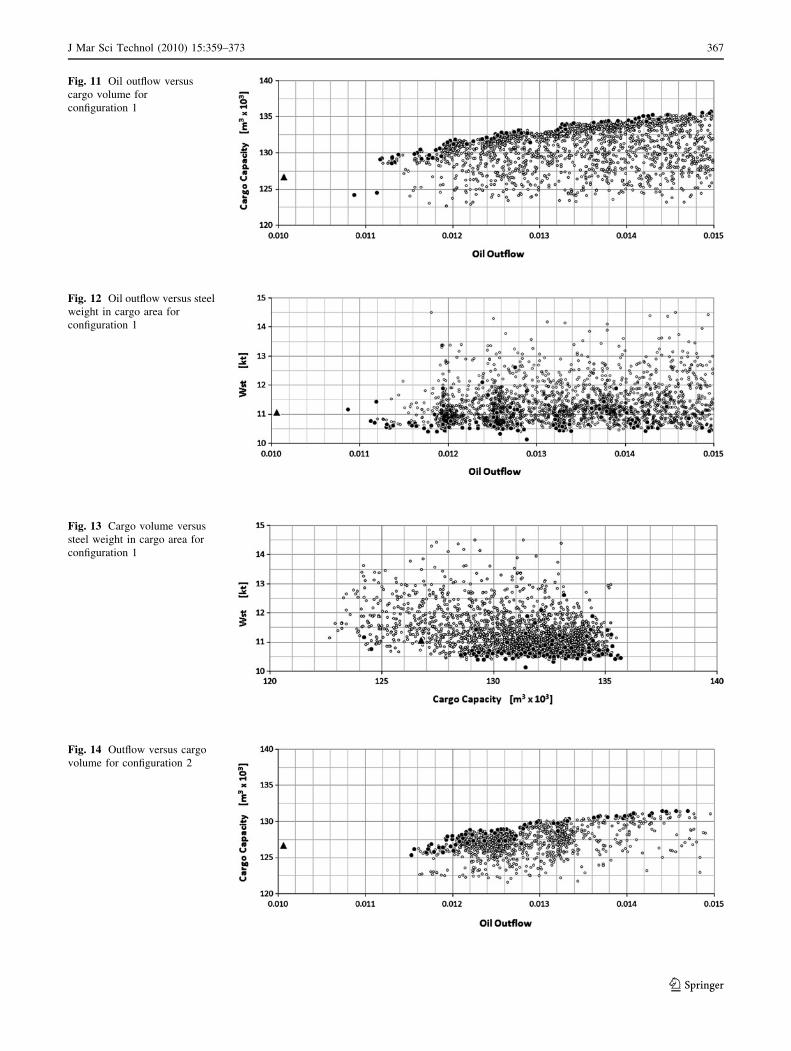
Fig. 11 Oil outflow versus
cargo volume for
configuration 1
Fig. 12 Oil outflow versus steel
weight in cargo area for
configuration 1
Fig. 13 Cargo volume versus
steel weight in cargo area for
configuration 1
Fig. 14 Outflow versus cargo
volume for configuration 2
J Mar Sci Technol (2010) 15:359–373 367
123
• None of the corrugated arrangements proved to be better
than the flat bulkhead designs. This does not mean that
the corrugated geometries should be disregarded as
alternative configurations in general. They have impor-
tant advantages in terms of ease of production and
maintenance that have not been considered in this study.
Fig. 15 Outflow versus steel
weight in cargo area for
configuration 2
Fig. 16 Cargo volume versus
steel weight in cargo area for
configuration 2
Fig. 17 Outflow versus cargo
volume for configuration 3
Fig. 18 Outflow versus steel
weight in cargo area for
configuration 3
368 J Mar Sci Technol (2010) 15:359–373
123
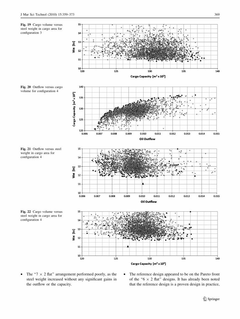
• The ‘‘7 9 2 flat’’ arrangement performed poorly, as the
steel weight increased without any significant gains in
the outflow or the capacity.
• The reference design appeared to be on the Pareto front
of the ‘‘6 9 2 flat’’ designs. It has already been noted
that the reference design is a proven design in practice,
Fig. 19 Cargo volume versus
steel weight in cargo area for
configuration 3
Fig. 20 Outflow versus cargo
volume for configuration 4
Fig. 21 Outflow versus steel
weight in cargo area for
configuration 4
Fig. 22 Cargo volume versus
steel weight in cargo area for
configuration 4
J Mar Sci Technol (2010) 15:359–373 369
123
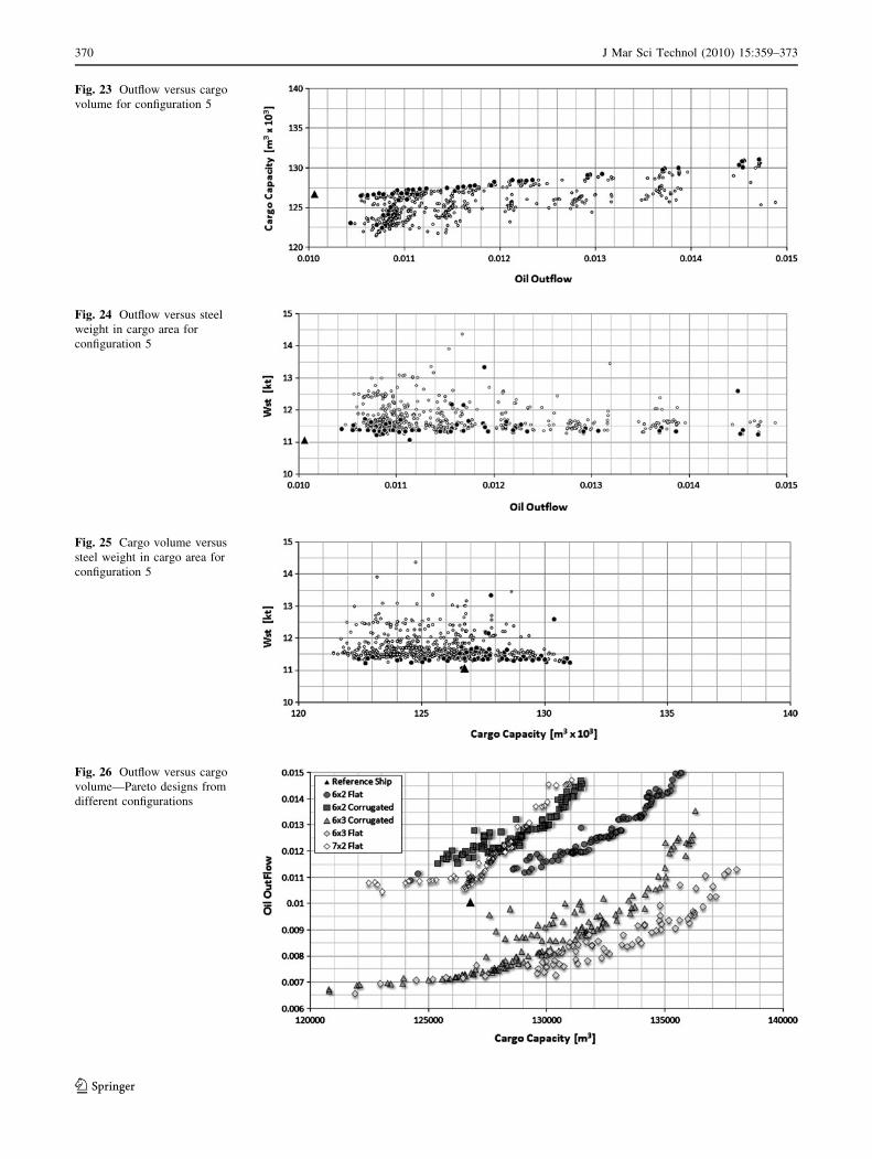
Fig. 23 Outflow versus cargo
volume for configuration 5
Fig. 24 Outflow versus steel
weight in cargo area for
configuration 5
Fig. 25 Cargo volume versus
steel weight in cargo area for
configuration 5
Fig. 26 Outflow versus cargo
volume—Pareto designs from
different configurations
370 J Mar Sci Technol (2010) 15:359–373
123
which was optimized with respect to steel weight (by
the yard designer, most likely using FEM).
• The proof of the dominance of the ‘‘6 9 3 flat’’ designs
holds for this particular AFRAMAX vessel size, which
is on the border with that of SUEZMAX.
5.3 Multi-criteria decision-making (MCDM) problem
and optimal design selection
Two different MCDM scenarios were examined using the
utility functions technique [9]:
Fig. 27 Cargo volume versus
steel weight in cargo area—
Pareto designs from different
configurations
Fig. 28 Outflow versus steel
weight in cargo area—Pareto
designs from different
configurations
Fig. 29 Design ranking
according to scenario #1
J Mar Sci Technol (2010) 15:359–373 371
123
1. Scenario #1: the same preference for all objectives is
assumed; see Fig. 29, Eq. 5, Table 3.
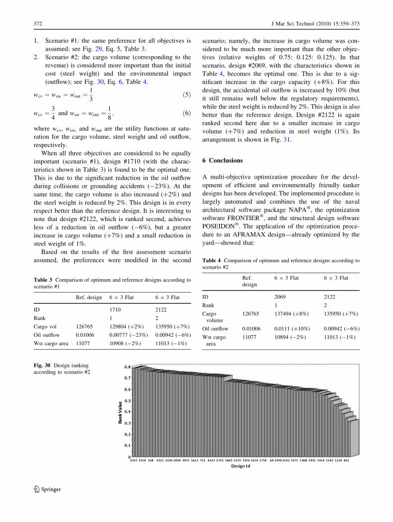
2. Scenario #2: the cargo volume (corresponding to the
revenue) is considered more important than the initial
cost (steel weight) and the environmental impact
(outflow); see Fig. 30, Eq. 6, Table 4.
wcv ¼ wsw ¼ wout ¼1
3ð5Þ
wcv ¼3
4and wsw ¼ wout ¼
1
8; ð6Þ
where wcv, wsw, and wout are the utility functions at satu-
ration for the cargo volume, steel weight and oil outflow,
respectively.
When all three objectives are considered to be equally
important (scenario #1), design #1710 (with the charac-
teristics shown in Table 3) is found to be the optimal one.
This is due to the significant reduction in the oil outflow
during collisions or grounding accidents (-23%). At the
same time, the cargo volume is also increased (?2%) and
the steel weight is reduced by 2%. This design is in every
respect better than the reference design. It is interesting to
note that design #2122, which is ranked second, achieves
less of a reduction in oil outflow (-6%), but a greater
increase in cargo volume (?7%) and a small reduction in
steel weight of 1%.
Based on the results of the first assessment scenario
assumed, the preferences were modified in the second
scenario; namely, the increase in cargo volume was con-
sidered to be much more important than the other objec-
tives (relative weights of 0.75: 0.125: 0.125). In that
scenario, design #2069, with the characteristics shown in
Table 4, becomes the optimal one. This is due to a sig-
nificant increase in the cargo capacity (?8%). For this
design, the accidental oil outflow is increased by 10% (but
it still remains well below the regulatory requirements),
while the steel weight is reduced by 2%. This design is also
better than the reference design. Design #2122 is again
ranked second here due to a smaller increase in cargo
volume (?7%) and reduction in steel weight (1%). Its
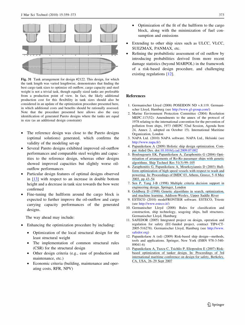
arrangement is shown in Fig. 31.
6 Conclusions
A multi-objective optimization procedure for the devel-
opment of efficient and environmentally friendly tanker
designs has been developed. The implemented procedure is
largely automated and combines the use of the naval
architectural software package NAPA�, the optimization
software FRONTIER�, and the structural design software
POSEIDON�. The application of the optimization proce-
dure to an AFRAMAX design—already optimized by the
yard—showed that:
Table 3 Comparison of optimum and reference designs according to
scenario #1
Ref. design 6 9 3 Flat 6 9 3 Flat
ID 1710 2122
Rank 1 2
Cargo vol 126765 129804 (?2%) 135950 (?7%)
Oil outflow 0.01006 0.00777 (-23%) 0.00942 (-6%)
Wst cargo area 11077 10908 (-2%) 11013 (-1%)
Fig. 30 Design ranking
according to scenario #2
Table 4 Comparison of optimum and reference designs according to
scenario #2
Ref.
design
6 9 3 Flat 6 9 3 Flat
ID 2069 2122
Rank 1 2
Cargo
volume
126765 137494 (?8%) 135950 (?7%)
Oil outflow 0.01006 0.0111 (?10%) 0.00942 (-6%)
Wst cargo
area
11077 10894 (-2%) 11013 (-1%)
372 J Mar Sci Technol (2010) 15:359–373
123
• The reference design was close to the Pareto designs
(optimal solutions) generated, which confirms the
validity of the modeling set-up
• Several Pareto designs exhibited improved oil-outflow
performances and comparable steel weights and capac-
ities to the reference design, whereas other designs
showed improved capacities but slightly worse oil-
outflow performances
• Particular design features of optimal designs observed
in [13] with respect to an increase in double bottom
height and a decrease in tank size towards the bow were
confirmed
• Fine-tuning the hullform around the cargo block is
expected to further improve the oil-outflow and cargo
carrying capacity performances of the generated
designs.
The way ahead may include:
• Enhancing the optimization procedure by including:
• Optimization of the local structural design for the
least structural weight
• The implementation of common structural rules
(CSR) for the structural design
• Other design criteria (e.g., ease of production and
maintenance, etc.)
• Economic criteria (building, maintenance and oper-
ating costs, RFR, NPV)
• Optimization of the fit of the hullform to the cargo
block, along with the minimization of fuel con-
sumption and emissions
• Extending to other ship sizes such as ULCC, VLCC,
SUEZMAX, PANMAX, etc.
• Refining the probabilistic assessment of oil outflow by
introducing probabilities derived from more recent
damage statistics (beyond MARPOL) in the framework
of a risk-based design procedure, and challenging
existing regulations [12].
References
1. Germanischer Lloyd (2008) POSEIDON ND v.8.119. Germani-
scher Lloyd, Hamburg (see http://www.gl-group.com/)
2. Marine Environment Protection Committee (2004) Resolution
MEPC.117(52): Amendments to the annex of the protocol of
1978 relating to the international convention for the prevention of
pollution from ships, 1973 (MEPC 52nd Session, Agenda Item
24, Annex 2, adopted on October 15). International Maritime
Organization, London
3. NAPA Ltd. (2010) NAPA software. NAPA Ltd., Helsinki (see
http://www.napa.fi/)
4. Papanikolaou A (2009) Holistic ship design optimization. Com-
put Aided Des. doi:10.1016/j.cad.2009.07.002
5. Boulougouris EK, Papanikolaou A, Zaraphonitis G (2004) Opti-
misation of arrangements of Ro-Ro passenger ships with genetic
algorithms. Ship Technol Res 51(3):99–105
6. Zaraphonitis G, Papanikolaou A, Mourkoyiannis D (2003) Hull-
form optimization of high speed vessels with respect to wash and
powering. In: Proceedings of IMDC 03, Athens, Greece, 5–8 May
2003, pp 43–54
7. Sen P, Yang J-B (1998) Multiple criteria decision support in
engineering design. Springer, London
8. Goldberg D (1998) Genetic algorithms in search, optimization,
and machine learning. Addison-Wesley, Upper Saddle River
9. ESTECO (2010) modeFRONTIER software. ESTECO, Trieste
(see http://www.esteco.it/)
10. Germanischer Lloyd (2008) Rules for classification and
construction, ship technology, seagoing ships, hull structures.
Germanischer Lloyd, Hamburg
11. SAFEDOR (2005) Integrated project on design, operation and
regulation for safety (EU-funded project, contract TIP4-CT-
2005-516278). Germanischer Lloyd, Hamburg (see http://www.
safedor.org)
12. Papanikolaou A (ed) (2009) Risk-based ship design—methods,
tools and applications. Springer, New York (ISBN 978-3-540-
89041-6)
13. Papanikolaou A, Tuzcu C, Tsichlis P, Eliopoulou E (2007) Risk-
based optimization of tanker design. In: Proceedings of 3rd
international maritime conference on design for safety, Berkeley,
CA, USA, 26–29 Sept 2007
Fig. 31 Tank arrangement for design #2122. This design, for which
the tank length was varied lengthwise, demonstrates that finding the
best cargo tank sizes to optimize oil outflow, cargo capacity and steel
weight is not a trivial task, though equally sized tanks are preferable
from a production point of view. In fact, the likely additional
production cost for this flexibility in tank sizes should also be
considered in an update of the optimization procedure presented here,
in which additional costs and benefits should be rationally assessed.
Note that the procedure presented here allows also the easy
identification of generated Pareto designs where the tanks are equal
in size (as an additional design constraint)
J Mar Sci Technol (2010) 15:359–373 373
123
Related Documents