Citation: Heredia-Aricapa, Y.; Belman-Flores, J.M.; Soria-Alcaraz, J.A.; Pérez-García, V.; Elizalde-Blancas, F.; Alfaro-Ayala, J.A.; Ramírez-Minguela, J. Multi-Objective Optimization of a Multilayer Wire-on-Tube Condenser: Case Study R134a, R600a, and R513A. Energies 2022, 15, 6101. https:// doi.org/10.3390/en15176101 Academic Editor: Ciro Aprea Received: 28 July 2022 Accepted: 18 August 2022 Published: 23 August 2022 Publisher’s Note: MDPI stays neutral with regard to jurisdictional claims in published maps and institutional affil- iations. Copyright: © 2022 by the authors. Licensee MDPI, Basel, Switzerland. This article is an open access article distributed under the terms and conditions of the Creative Commons Attribution (CC BY) license (https:// creativecommons.org/licenses/by/ 4.0/). energies Article Multi-Objective Optimization of a Multilayer Wire-on-Tube Condenser: Case Study R134a, R600a, and R513A Yonathan Heredia-Aricapa 1 , Juan M. Belman-Flores 1, * , Jorge A. Soria-Alcaraz 2 , Vicente Pérez-García 1 , Francisco Elizalde-Blancas 1, *, Jorge A. Alfaro-Ayala 3 and José Ramírez-Minguela 3 1 Department of Mechanical Engineering, Engineering Division, Campus Irapuato-Salamanca, University of Guanajuato, Guanajuato 36885, Mexico 2 Departamento de Estudios Organizacionales, División de Ciencias Económico Administrativas, University of Guanajuato, Guanajuato 36885, Mexico 3 Department of Chemical Engineering, DCNE, University of Guanajuato, Guanajuato 36885, Mexico * Correspondence: [email protected] (J.M.B.-F.); [email protected] (F.E.-B.); Tel.: +52-464-647-9940 (J.M.B.-F.) Abstract: This study presents the optimization of a multilayer wire-on-tube condenser exposed to forced convection, using the Optimized Multi-objective Particle Swarm Optimization (OMOPSO) algorithm. The maximization of the heat transfer and the minimization of the heat exchange area were defined as objective functions. In the optimization process, the variations of eight geomet- ric parameters of the condenser were analyzed, and the Multi-objective Evolutionary Algorithm based on Decomposition (MOEAD), Non-dominated Sorting Genetic Algorithm-II (NSGAII), and OMOPSO algorithms were statistically explored. Furthermore, the condenser optimization analysis was extended to the use of alternative refrigerants to R134a such as R600a and R513A. Among the relevant results, it can be commented that the OMOPSO algorithm presented the best option from the statistical point of view compared to the other two algorithms. Thus, optimal designs for the wire-on- tube condenser were defined for three proposed study cases and for each refrigerant, providing an overview of compact designs. Likewise, the reduction of the condenser area was analyzed in more detail, presenting a maximum reduction of 15% for the use of R134a compared to for the current design. Finally, the crossflow condition was studied with respect to the current one, concluding in a greater heat transfer and a smaller heat exchange surface. Keywords: domestic refrigerator; MOEAD; NSGAII; OMOPSO; refrigerants 1. Introduction Heat exchangers are widely used equipment in different sectors such as industrial, transportation, pharmaceutical, refrigeration, and air conditioning. They represent a key role in the efficiency of each system of which they are part. In recent years, there has been great interest in implementing various optimization methods to improve the design of the equipment. Increasing heat transfer per unit area, reducing manufacturing costs [1], and saving energy consumption [2] are among the main objectives for optimizing heat exchangers. For example, the optimization methodologies are specifically applied to wire- on-tube heat exchangers such as the one developed by Bansal and Chin [3], in which they proposed an optimization factor based on the thermal capacity per unit weight of a wire-on-tube condenser. That study was based on the development of a mathematical model, obtaining a 3% gain in thermal capacity and a 6% reduction in the condenser weight. Zhang et al. [4] experimentally developed the optimization of the airflow field of a spiral wire-on-tube condenser by forced convection. In doing so, they achieved a 2.37% reduction in energy consumption. On the other hand, multi-objective optimization is one of the applications in the engineering of genetic algorithms. This can be evidenced in a previous study [5], in which Energies 2022, 15, 6101. https://doi.org/10.3390/en15176101 https://www.mdpi.com/journal/energies

Welcome message from author
This document is posted to help you gain knowledge. Please leave a comment to let me know what you think about it! Share it to your friends and learn new things together.
Transcript

Citation: Heredia-Aricapa, Y.;
Belman-Flores, J.M.; Soria-Alcaraz,
J.A.; Pérez-García, V.;
Elizalde-Blancas, F.; Alfaro-Ayala,
J.A.; Ramírez-Minguela, J.
Multi-Objective Optimization of a
Multilayer Wire-on-Tube Condenser:
Case Study R134a, R600a, and R513A.
Energies 2022, 15, 6101. https://
doi.org/10.3390/en15176101
Academic Editor: Ciro Aprea
Received: 28 July 2022
Accepted: 18 August 2022
Published: 23 August 2022
Publisher’s Note: MDPI stays neutral
with regard to jurisdictional claims in
published maps and institutional affil-
iations.
Copyright: © 2022 by the authors.
Licensee MDPI, Basel, Switzerland.
This article is an open access article
distributed under the terms and
conditions of the Creative Commons
Attribution (CC BY) license (https://
creativecommons.org/licenses/by/
4.0/).
energies
Article
Multi-Objective Optimization of a Multilayer Wire-on-TubeCondenser: Case Study R134a, R600a, and R513AYonathan Heredia-Aricapa 1, Juan M. Belman-Flores 1,* , Jorge A. Soria-Alcaraz 2 , Vicente Pérez-García 1,Francisco Elizalde-Blancas 1,*, Jorge A. Alfaro-Ayala 3 and José Ramírez-Minguela 3
1 Department of Mechanical Engineering, Engineering Division, Campus Irapuato-Salamanca,University of Guanajuato, Guanajuato 36885, Mexico
2 Departamento de Estudios Organizacionales, División de Ciencias Económico Administrativas,University of Guanajuato, Guanajuato 36885, Mexico
3 Department of Chemical Engineering, DCNE, University of Guanajuato, Guanajuato 36885, Mexico* Correspondence: [email protected] (J.M.B.-F.); [email protected] (F.E.-B.);
Tel.: +52-464-647-9940 (J.M.B.-F.)
Abstract: This study presents the optimization of a multilayer wire-on-tube condenser exposed toforced convection, using the Optimized Multi-objective Particle Swarm Optimization (OMOPSO)algorithm. The maximization of the heat transfer and the minimization of the heat exchange areawere defined as objective functions. In the optimization process, the variations of eight geomet-ric parameters of the condenser were analyzed, and the Multi-objective Evolutionary Algorithmbased on Decomposition (MOEAD), Non-dominated Sorting Genetic Algorithm-II (NSGAII), andOMOPSO algorithms were statistically explored. Furthermore, the condenser optimization analysiswas extended to the use of alternative refrigerants to R134a such as R600a and R513A. Among therelevant results, it can be commented that the OMOPSO algorithm presented the best option from thestatistical point of view compared to the other two algorithms. Thus, optimal designs for the wire-on-tube condenser were defined for three proposed study cases and for each refrigerant, providing anoverview of compact designs. Likewise, the reduction of the condenser area was analyzed in moredetail, presenting a maximum reduction of 15% for the use of R134a compared to for the currentdesign. Finally, the crossflow condition was studied with respect to the current one, concluding in agreater heat transfer and a smaller heat exchange surface.
Keywords: domestic refrigerator; MOEAD; NSGAII; OMOPSO; refrigerants
1. Introduction
Heat exchangers are widely used equipment in different sectors such as industrial,transportation, pharmaceutical, refrigeration, and air conditioning. They represent a keyrole in the efficiency of each system of which they are part. In recent years, there has beengreat interest in implementing various optimization methods to improve the design ofthe equipment. Increasing heat transfer per unit area, reducing manufacturing costs [1],and saving energy consumption [2] are among the main objectives for optimizing heatexchangers. For example, the optimization methodologies are specifically applied to wire-on-tube heat exchangers such as the one developed by Bansal and Chin [3], in whichthey proposed an optimization factor based on the thermal capacity per unit weight ofa wire-on-tube condenser. That study was based on the development of a mathematicalmodel, obtaining a 3% gain in thermal capacity and a 6% reduction in the condenser weight.Zhang et al. [4] experimentally developed the optimization of the airflow field of a spiralwire-on-tube condenser by forced convection. In doing so, they achieved a 2.37% reductionin energy consumption.
On the other hand, multi-objective optimization is one of the applications in theengineering of genetic algorithms. This can be evidenced in a previous study [5], in which
Energies 2022, 15, 6101. https://doi.org/10.3390/en15176101 https://www.mdpi.com/journal/energies
Energies 2022, 15, 6101 2 of 14
a multi-objective optimization applied to a plate heat exchanger was proposed in order tomaximize the overall heat transfer coefficient and minimize the pressure drop by analyzingeight geometric variables. Imran et al. [6] performed a thermo-hydraulic optimization byanalyzing different geometrical parameters. The authors obtained that the heat transfer andthe pressure drop increase with the increase in the horizontal port center distance and thenumber of plates. Kumar et al. [7] developed an optimization technique by implementingthe MOWO meta-heuristic algorithm. The authors demonstrated the effectiveness of thisalgorithm in thermal and hydraulic optimization. Sodagar-Abardeh et al. [8] determinedthe optimal geometry and flow conditions of plate heat exchangers based on the entropygeneration minimization approach.
Other multi-objective algorithms found in the literature and applied to the opti-mization of heat exchangers are the bat algorithm [9], MOGA [10], Bees algorithm [11],NSGAII [12], constructal theory [13], MOHTS [14], cohort intelligence [15], and FOA [16];all of them involving objectives such as cost minimization, efficiency increase, and reducedpressure drop. One of the most widely used algorithms in optimization studies is theNSGAII, proposed by Deb et al. [17], with the purpose to improve some characteristicssuch as computational complexity, non-elitism approaches, and the need to specify a distri-bution parameter. In this regard, Sanaye and Hajabdollahi [18] presented a mathematicalmodel using the ε-NTU thermal analysis method for compact heat exchangers. Theyconsidered the variation of six geometric parameters and used the NSGAII algorithm toachieve the maximum effectiveness and the minimum annual investment and operatingcost. Rodríguez et al. [19] proposed a flexible optimization procedure using NSGAII forseveral types of fluids and for multiple shell and tube heat exchanger designs. They con-cluded that the length of the tube had the greatest influence, not only on the value ofthe ecological function, but also on the cost. Liu et al. [20] performed a combination ofCFD simulation and multi-objective optimization to improve the performance of a heatexchanger by optimizing the Colburn factor and the friction factor.
OMOPSO is another multi-objective optimization algorithm presented by Sierra andCoello [21]. With this algorithm, the exploration and exploitation capacity were improvedduring the search process by dividing the population into sub-swarms of equal size andadapting each of them to a different mutation operator. Although it has been little usedin heat exchangers optimization, comparisons between NSGAII and OMOPSO can befound in different works [22,23], in which it is reported that the OMOPSO algorithmpresents better results with a lower error rate. The main motivation for the use of geneticalgorithms in multi-objective problem solving is that they can return a set of non-dominatedsolutions that converge to a Pareto optimal front, providing the possibility of searching inlimited spaces.
According to the literature review, it can be seen that most of the studies focus onoptimization of the compact, plate, and shell-and-tube heat exchangers, concentrating onthe optimization of costs and geometric parameters to improve their thermo-hydraulicbehavior. Therefore, the studies of wire-on-tube heat exchangers focused on optimizationare limited. In the domestic refrigeration industry, one of the most widely used heatexchanger designs is the wire-on-tube heat exchanger design, mainly due to its low costand ease of manufacture [24].
In the present work, the optimization of a multilayer wire-on-tube condenser used indomestic refrigeration was proposed, where the analysis of eight geometric parameters onthe thermal behavior of the heat exchanger was suggested. In addition, the use of alternativerefrigerants such as R600a and R513A as substitutes for R134a was experimentally studied.These refrigerants had similar thermophysical properties to R134a. In addition to this,R513A had a 56% reduction in its GWP compared to R134a. R600a had a GWP of 10 and wasconsidered a long-term solution. Therefore, these refrigerants were taken as alternatives,because they presented a reduction in the direct impact on the environment with respectto R134a.
Energies 2022, 15, 6101 3 of 14
The results presented the optimal geometric configurations that maximized heattransfer with a reduction in the heat exchanger area for all three refrigerants. Thus, themain objective of this work was to explore the application of fully documented multi-objective algorithms (NSGAII, OMOPSO, and MOEAD) in the optimization of a multilayerwire-on-tube condenser used in domestic refrigeration.
The results presented the optimal geometric configurations that maximized heattransfer with a reduction in heat exchanger area for all three refrigerants, with respect tothe operating point obtained experimentally for each refrigerant. In addition to this, thiswork was proposed as a guideline to obtaining design parameters for the constructionof new equipment that present a better thermal performance under different establishedoperating conditions.
In this work, the multilayer wire-on-tube condenser used was described, the objectivefunctions were defined, and the basic concepts of the algorithms used were defined. Then,a qualitative and statistical comparison is presented for the selection of the multi-objectiveoptimization algorithm; finally, the results obtained and the main conclusions of the workare presented.
2. General Aspects and Optimization2.1. Multilayer Wire-on-Tube Condenser
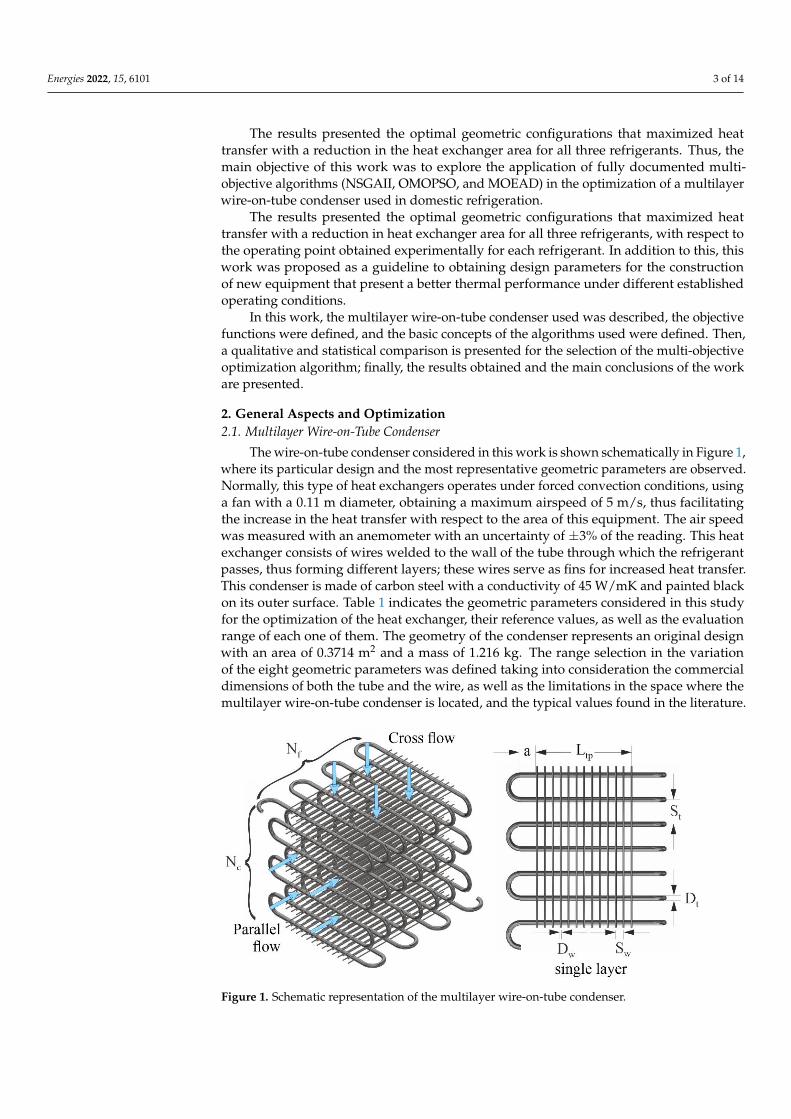
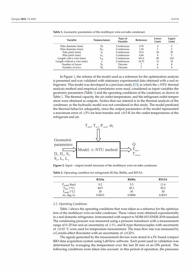
The wire-on-tube condenser considered in this work is shown schematically in Figure 1,where its particular design and the most representative geometric parameters are observed.Normally, this type of heat exchangers operates under forced convection conditions, usinga fan with a 0.11 m diameter, obtaining a maximum airspeed of 5 m/s, thus facilitatingthe increase in the heat transfer with respect to the area of this equipment. The air speedwas measured with an anemometer with an uncertainty of ±3% of the reading. This heatexchanger consists of wires welded to the wall of the tube through which the refrigerantpasses, thus forming different layers; these wires serve as fins for increased heat transfer.This condenser is made of carbon steel with a conductivity of 45 W/mK and painted blackon its outer surface. Table 1 indicates the geometric parameters considered in this studyfor the optimization of the heat exchanger, their reference values, as well as the evaluationrange of each one of them. The geometry of the condenser represents an original designwith an area of 0.3714 m2 and a mass of 1.216 kg. The range selection in the variationof the eight geometric parameters was defined taking into consideration the commercialdimensions of both the tube and the wire, as well as the limitations in the space where themultilayer wire-on-tube condenser is located, and the typical values found in the literature.
Energies 2022, 15, x FOR PEER REVIEW 3 of 14
of 10 and was considered a long-term solution. Therefore, these refrigerants were taken
as alternatives, because they presented a reduction in the direct impact on the environ-
ment with respect to R134a.
The results presented the optimal geometric configurations that maximized heat
transfer with a reduction in the heat exchanger area for all three refrigerants. Thus, the
main objective of this work was to explore the application of fully documented multi-
objective algorithms (NSGAII, OMOPSO, and MOEAD) in the optimization of a multi-
layer wire-on-tube condenser used in domestic refrigeration.
The results presented the optimal geometric configurations that maximized heat
transfer with a reduction in heat exchanger area for all three refrigerants, with respect to
the operating point obtained experimentally for each refrigerant. In addition to this, this
work was proposed as a guideline to obtaining design parameters for the construction of
new equipment that present a better thermal performance under different established op-
erating conditions.
In this work, the multilayer wire-on-tube condenser used was described, the objec-
tive functions were defined, and the basic concepts of the algorithms used were defined.
Then, a qualitative and statistical comparison is presented for the selection of the multi-
objective optimization algorithm; finally, the results obtained and the main conclusions of
the work are presented.
2. General Aspects and Optimization
2.1. Multilayer Wire-on-Tube Condenser
The wire-on-tube condenser considered in this work is shown schematically in Fig-
ure 1, where its particular design and the most representative geometric parameters are
observed. Normally, this type of heat exchangers operates under forced convection con-
ditions, using a fan with a 0.11 m diameter, obtaining a maximum airspeed of 5 m/s, thus
facilitating the increase in the heat transfer with respect to the area of this equipment. The
air speed was measured with an anemometer with an uncertainty of ±3% of the reading.
This heat exchanger consists of wires welded to the wall of the tube through which the
refrigerant passes, thus forming different layers; these wires serve as fins for increased
heat transfer. This condenser is made of carbon steel with a conductivity of 45 W/mK and
painted black on its outer surface. Table 1 indicates the geometric parameters considered
in this study for the optimization of the heat exchanger, their reference values, as well as
the evaluation range of each one of them. The geometry of the condenser represents an
original design with an area of 0.3714 m2 and a mass of 1.216 kg. The range selection in
the variation of the eight geometric parameters was defined taking into consideration the
commercial dimensions of both the tube and the wire, as well as the limitations in the
space where the multilayer wire-on-tube condenser is located, and the typical values
found in the literature.
Figure 1. Schematic representation of the multilayer wire-on-tube condenser.
Energies 2022, 15, 6101 4 of 14
Table 1. Geometric parameters of the multilayer wire-on-tube condenser.
Variable Nomenclature Type ofVariable Reference Lower
LimitUpperLimit
Tube diameter (mm) Dt Continuous 4.76 4 6Wire diameter (mm) Dw Continuous 1.30 1 2
Tube pitch (mm) St Continuous 25.4 20 30Wire pitch (mm) Sw Continuous 4.06 4 5
Length with a wire (mm) Ltp Continuous 101.6 80 120Length without a wire (mm) a Continuous 16.72 12 18
Number of layers Nc Discrete 7 6 8Number of rows Nf Discrete 7 6 8
In Figure 2, the scheme of the model used as a reference for the optimization analysisis presented and was validated with stationary experimental data obtained with a real re-frigerator. This model was developed in a previous study [25], in which the ε-NTU thermalanalysis method and empirical correlations were used, considered as input variables thegeometric parameters (Table 1) and the operating conditions of the condenser, as shown inTable 2. The thermal capacity, the air outlet temperature, and the refrigerant outlet temper-ature were obtained as outputs. Notice that our interest is in the thermal analysis of thecondenser, so the hydraulic model was not considered in this study. The model predictedthe thermal behavior adequately, since the output parameters of the model representeda maximum error of ±5% for heat transfer and ±0.5 K for the outlet temperatures of therefrigerant and air.
Energies 2022, 15, x FOR PEER REVIEW 4 of 14
Figure 1. Schematic representation of the multilayer wire-on-tube condenser.
Table 1. Geometric parameters of the multilayer wire-on-tube condenser.
Variable Nomenclature Type of Variable Reference Lower
Limit
Upper
Limit
Tube diameter (mm) Dt Continuous 4.76 4 6
Wire diameter (mm) Dw Continuous 1.30 1 2
Tube pitch (mm) St Continuous 25.4 20 30
Wire pitch (mm) Sw Continuous 4.06 4 5
Length with a wire (mm) Ltp Continuous 101.6 80 120
Length without a wire (mm) a Continuous 16.72 12 18
Number of layers Nc Discrete 7 6 8
Number of rows Nf Discrete 7 6 8
In Figure 2, the scheme of the model used as a reference for the optimization analysis
is presented and was validated with stationary experimental data obtained with a real
refrigerator. This model was developed in a previous study [25], in which the ε-NTU ther-
mal analysis method and empirical correlations were used, considered as input variables
the geometric parameters (Table 1) and the operating conditions of the condenser, as
shown in Table 2. The thermal capacity, the air outlet temperature, and the refrigerant
outlet temperature were obtained as outputs. Notice that our interest is in the thermal
analysis of the condenser, so the hydraulic model was not considered in this study. The
model predicted the thermal behavior adequately, since the output parameters of the
model represented a maximum error of ±5% for heat transfer and ±0.5 K for the outlet
temperatures of the refrigerant and air.
Figure 2. Input−output model structure of the multilayer wire-on-tube condenser.
Table 2. Operating condition for refrigerants R134a, R600a, and R513A.
R134a R600a R513A
Pcond (bar) 9.2 5.3 11.4
Tin,r (°C) 44.5 45.1 50.2
Tamb (°C) 30 30 30
m𝑟 (kg/s) 0.0013 0.0006 0.0013
2.2. Operating Conditions
Table 2 shows the operating conditions that were taken as a reference for the optimi-
zation of the multilayer wire-on-tube condenser. These values were obtained experimen-
tally in a real domestic refrigerator, instrumented with respect to NOM-015-ENER-2018
standard. The condensing pressure was measured using a pressure transducer with a
measurement range of 0–25 bar and an uncertainty of ±1%, and K-type thermocouples
with uncertainty of ±0.03 °C were used for temperature measurement. The mass flow rate
was measured by a Coriolis-effect flowmeter with an uncertainty of ±0.22%.
Figure 2. Input−output model structure of the multilayer wire-on-tube condenser.
Table 2. Operating condition for refrigerants R134a, R600a, and R513A.
R134a R600a R513A
Pcond (bar) 9.2 5.3 11.4Tin,r (◦C) 44.5 45.1 50.2Tamb (◦C) 30 30 30.
mr (kg/s) 0.0013 0.0006 0.0013
2.2. Operating Conditions
Table 2 shows the operating conditions that were taken as a reference for the optimiza-tion of the multilayer wire-on-tube condenser. These values were obtained experimentallyin a real domestic refrigerator, instrumented with respect to NOM-015-ENER-2018 standard.The condensing pressure was measured using a pressure transducer with a measurementrange of 0–25 bar and an uncertainty of ±1%, and K-type thermocouples with uncertaintyof ±0.03 ◦C were used for temperature measurement. The mass flow rate was measured bya Coriolis-effect flowmeter with an uncertainty of ±0.22%.
The signals generated by the measurement devices were stored in a PC-based compactRIO data acquisition system using LabView software. Each point used in validation wasdetermined by averaging the temperature over the last 20 min of an ON period. Thefollowing conditions were taken into account: in this period of operation, the pressures

Energies 2022, 15, 6101 5 of 14
and temperatures of the inlet and the outlet of the air and the refrigerant in the condenserwere known.
2.3. Proposed Objective Functions
The multi-objective optimization considered in this work is defined in a general wayby the following equation:
F1,2 (x) = [ f1(x), f2(x) . . . fn(x)], (1)
where F(x) represents the objective functions to maximize/minimize the heat transfer, andf (x) are the geometric optimization parameters mentioned in Table 1, n represents thenumber of parameters. For this case study, n = 8. Considering the maximization of the heattransfer and the minimization of the exchanger area, a multiple set of optimal solutions,known as Pareto optimal solutions, are obtained.
According to the model developed for the wire-on-tube condenser [25], the twoobjective functions that were defined in this work are shown in Equations (2) and (3). Thetotal heat transfer of the condenser,
.Q, was estimated considering three zones with respect
to the refrigerant state, desuperheating, condensation, and subcooling. In each zone, anenergy balance is applied between both fluids (the refrigerant and the air). While exchangearea, AT, is provided by the wire area and the tube area:
.Q =
.Qdsh +
.Qcond +
.Qsub, (2)
AT = Aw + At, (3)
Aw = πDwLwNw, (4)
At = πDtLt. (5)
The relationships shown in Equations (6)–(8) are defined to obtain the total exchangerarea as a function of the geometric design parameters:
Lt =(
Ltp + 2a)
N f Nc +πSt
2
((N f − 1
)+ N f (Nc − 1)
), (6)
Nw = 2Nc
(Ltp
Sw+ 1
), (7)
Lw = St
(N f − 1
)+
St
2. (8)
In this work, different operating conditions were evaluated for the thermal behaviorof the wire-on-tube condenser, which is mounted in a domestic refrigerator [25].
2.4. Algorithms
The NSGA-II algorithm [26] is presented as an improved version of the NSGA. NSGA-II uses an elitist principle, whereby the elites of a population are given an opportunity to becarried to the next generation. It is computationally more efficient than the NSGA, and it isa highly competitive algorithm in convergence. In addition, it uses an explicit diversity-preserving mechanism (crowding distance) and highlights non-dominated solutions. TheOMOPSO algorithm [27] develops an approach based on Pareto dominance and the useof an agglomeration factor for the selection of leaders, which is used to filter the numberof leaders when this exceeds the maximum limit imposed. These leaders are retainedconsidering the best crowding values. It also uses two external files, with one to store thebest positions of the current iteration and the other to store the non-dominated solutions.Finally, the MOEAD algorithm [28] decomposes multi-objective optimization problemsinto a series of single-objective optimization subproblems, by applying decompositionapproaches. Then, these subproblems are simultaneously optimized by using evolutionary

Energies 2022, 15, 6101 6 of 14
algorithms. The set of Pareto-oppressed solutions is obtained, because each solutioncorresponds to the optimal solution of each single-objective optimization subproblem. Thismethod has a great advantage of maintaining the distribution of solutions, and optimizationby analyzing information from adjacent problems can avoid falling into a local optimumdue to the existence of de-composition operations.
2.5. Case Study
To contribute with a broader view on the use of algorithms, this study initially pro-posed the evaluation of three algorithms: NSGAII, OMOPSO, and MOEAD, with a searchpopulation size of 100 individuals, a maximum of 250 iterations, and a mutation probabilityof 0.125. A statistical comparison was made between the proposed algorithms by evalu-ating the R134a, R600a, and R513A refrigerants used in the wire-on-tube condenser, theabove under the same simulation parameters, looking for the best response, that is, withthe lowest statistical variation of the results obtained for each refrigerant with respect tothe proposed objective functions.
As our first solver, we decided to use the 2001 version of NSGAII, because it ishistorically one of the most widely applied algorithms to a variety of continuous multi-objective problems with reasonably good results in the literature. This algorithm was onlythe initial approach to our experiments. The main idea of using this algorithm was toinitially explore the performance of a multilayer wire-on-tube condenser optimized byheuristic algorithms. Once we obtained encouraging results, we applied more sophisticatedalgorithms, namely, OMOPSO and MOEAD.
Once the algorithm based on the statistical results has been selected, three study casesrelated to the geometric design of the heat exchanger were proposed. In these cases, thenumber of layers, Nc, and the number of rows, Nf, were kept fixed, and the other geometricparameters were varied considering the two objective functions, the minimization of thearea and the maximization of the heat transfer. These three cases were defined as follows:case 1: Nc = Nf = 6; case 2: Nc = Nf = 7; and case 3: Nc = Nf = 8. Notice that a square (Nc = Nf)condenser section (exchanger side) was maintained, mainly considering the limitations inthe space of the refrigerator where the multilayer wire-on-tube condenser was installed.
3. Results and Discussion3.1. Analysis of the Optimization Algorithm
Figure 3 presents a qualitative comparison using boxplots obtained using the dataanalysis software R Studio, for the three optimization algorithms initially proposed inthis work (NSGAII, OMOPSO, and MOEAD). The information was obtained by run-ning 35 simulations for each algorithm and for each of the three refrigerants analyzed.Figure 3a,c,e shows the distribution of the data obtained for the minimization of the heattransfer area, and Figure 3b,d,f illustrates the data distribution for the maximization of theheat transfer, which were for the experimentally tested refrigerants.
Analyzing Figure 3a, a greater data dispersion was observed for the MOEAD andNSGAII algorithms, while for the OMOPSO algorithm there was a lower dispersion. InFigure 3c, for R600a refrigerant, it was observed that the MOEAD and OMOPSO algorithmspresented a lower data dispersion, including defining a smaller heat transfer area withrespect to the NSGAII algorithm. As for Figure 3e, for the R513A refrigerant, it wasobserved that the data dispersion was not very different between the algorithms; however,the NSGAII reflected the minimal heat transfer area. In the previous figures, some atypicalpoints were observed.
Regarding heat transfer and for the evaluation of R134a and R600a refrigerants, asshown in Figure 3b,d, respectively, it was observed that there was not dispersion in thedata obtained with the three algorithms, since the results did not present any variation.Although in the analysis for R513A refrigerant (Figure 3f), the MOEAD and OMOPSOalgorithms are similar, they did not present any dispersion in the results obtained. Withrespect to the NSGAII algorithm, a slight reduction of 0.06% in heat transfer was observed.

Energies 2022, 15, 6101 7 of 14
Although Figure 3f presents a minimum dispersion of data, this gives us a guideline fromthe statistical analysis to make the selection of the optimization algorithm.
Energies 2022, 15, x FOR PEER REVIEW 7 of 14
Figure 3. Statistical comparison between NSGAII, OMOPSO, and MOEAD algorithms. (a,c,e) heat
transfer area; (b,d,f) heat transfer.
Analyzing Figure 3a, a greater data dispersion was observed for the MOEAD and
NSGAII algorithms, while for the OMOPSO algorithm there was a lower dispersion. In
Figure 3c, for R600a refrigerant, it was observed that the MOEAD and OMOPSO algo-
rithms presented a lower data dispersion, including defining a smaller heat transfer area
with respect to the NSGAII algorithm. As for Figure 3e, for the R513A refrigerant, it was
Figure 3. Statistical comparison between NSGAII, OMOPSO, and MOEAD algorithms. (a,c,e) heattransfer area; (b,d,f) heat transfer.

Energies 2022, 15, 6101 8 of 14
Based on the analysis and the inspection of the box plots, this work proposed an opti-mization of the multilayer wire-on-tube condenser by using the OMOPSO algorithm, sinceit is relatively better and consistently outperforms the NSGAII and MOEAD algorithms.
To substantiate the use of the OMOPSO algorithm in this work and under the condi-tions of the model [25], Table 3 presents a summary of the statistical comparison, throughthe Tukey HSD pairwise test, among the algorithms presented in Figure 3, which was aspecific case for the heat transfer surface. In the first column, the evaluated refrigerantwas defined, and in the second column, a grouping of algorithms was proposed for theirrespective comparisons. The Diff column indicates the mean between the lower limit, lwr,and the upper limit, upr, of each confidence interval calculated at 95%. Finally, the value ofp adj indicates whether there was a significant difference in the use of the algorithms. Ap adj value of >0.05 means that there was not a statistically significant difference betweenthe compared algorithms.
Table 3. Statistical results between algorithms for R134a, R600a, and R513A refrigerants.
Refrigerant Algorithm Diff lwr upr p adj
R134aNSGAII-MOEAD 0.000000466 −0.000000902 0.000001833 0.6976122
OMOPSO-MOEAD −0.000001939 −0.000003307 −0.000000572 0.0029952OMOPSO-NSGAII −0.000002405 −0.000003773 −0.000001038 0.0001789
R600aNSGAII-MOEAD 0.001188397 0.000970156 0.001406639 0.0000000
OMOPSO-MOEAD 0.000159179 −0.000059061 0.000377421 0.1973007OMOPSO-NSGAII −0.001029218 −0.001247459 −0.000810977 0.0000000
R513ANSGAII-MOEAD −0.006567517 −0.007110653 −0.006024381 0.0000000
OMOPSO-MOEAD 0.000395047 −0.000148089 0.000938183 0.1990515OMOPSO-NSGAII 0.006962564 0.006419428 0.007505700 0.0000000
For the case of R134a, a p adj value of >0.05 was observed in the comparison ofthe NSGAII and MOEAD algorithms, which confirmed that there was not a significantdifference between the two algorithms. In the comparison between the OMOPSO and theMOEAD algorithms, a p adj value of <0.05 was observed, showing in this case that thetwo algorithms were statistically different, presenting better results with the OMOPSOalgorithm (see Figure 3a), a similar case to that presented in the comparison between theOMOPSO and NSGAII algorithms. With respect to the R600a refrigerant, it was observedthat the OMOPSO and MOEAD algorithms reflected the lowest dispersion of data, wherethey did not show up significant differences (p adj > 0.05). For the case of the analysiswith refrigerant R513A, the OMOPSO and MOEAD algorithms were statistically similar(p adj > 0.05); therefore, there was no significant difference between the results with the useof both algorithms.
3.2. Optimization Results
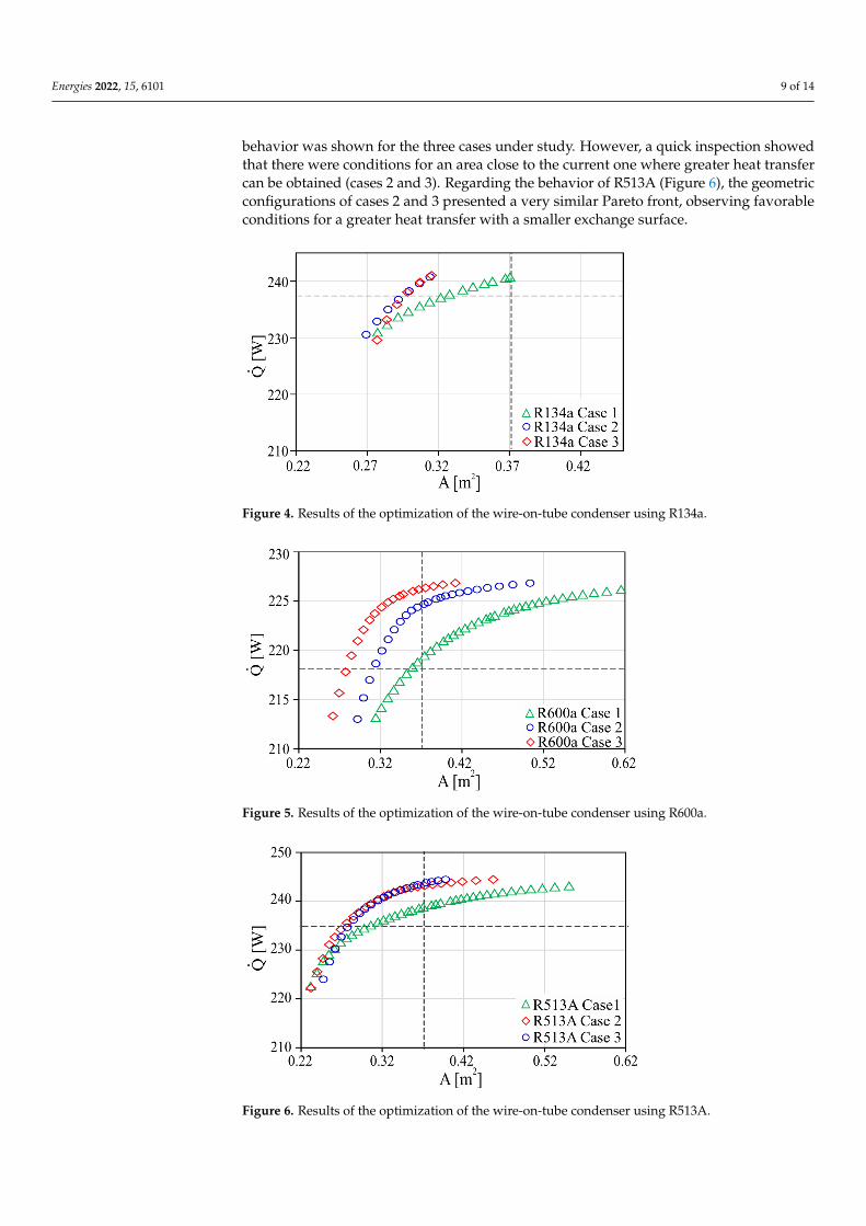
This section presents the main results of the multilayer wire-on-tube condenser op-timization process. The jMetalPy [29] and Python software were used to develop theoptimization scenarios [30]. Thus, Figures 4–6 show the Pareto front obtained from theoptimization using the OMOPSO algorithm for the refrigerants R134a, R600a, and R513A,respectively. The graphs in each figure show the behaviors for the three geometric casesproposed in this work, varying the number of layers and the number of rows. In addition,each graph also represents the current operating point for each refrigerant, which is markedby crossing the dotted lines.
In the case of the wire-on-tube condenser using R134a (Figure 4), a significant reductionin the heat exchanger area can be observed compared to the current state (line crossing)and a slight increase in the heat transfer of the equipment. Cases 2 and 3 presented verysimilar Pareto fronts compared to the case where a smaller number of layers and rows weredefined. For the analysis of the heat exchanger using R600a (Figure 5), a greater variation in
Energies 2022, 15, 6101 9 of 14
behavior was shown for the three cases under study. However, a quick inspection showedthat there were conditions for an area close to the current one where greater heat transfercan be obtained (cases 2 and 3). Regarding the behavior of R513A (Figure 6), the geometricconfigurations of cases 2 and 3 presented a very similar Pareto front, observing favorableconditions for a greater heat transfer with a smaller exchange surface.
Energies 2022, 15, x FOR PEER REVIEW 9 of 14
3.2. Optimization Results
This section presents the main results of the multilayer wire-on-tube condenser opti-
mization process. The jMetalPy [29] and Python software were used to develop the opti-
mization scenarios [30]. Thus, Figures 4–6 show the Pareto front obtained from the opti-
mization using the OMOPSO algorithm for the refrigerants R134a, R600a, and R513A, re-
spectively. The graphs in each figure show the behaviors for the three geometric cases
proposed in this work, varying the number of layers and the number of rows. In addition,
each graph also represents the current operating point for each refrigerant, which is
marked by crossing the dotted lines.
Figure 4. Results of the optimization of the wire-on-tube condenser using R134a.
Figure 5. Results of the optimization of the wire-on-tube condenser using R600a.
Figure 4. Results of the optimization of the wire-on-tube condenser using R134a.
Energies 2022, 15, x FOR PEER REVIEW 9 of 14
3.2. Optimization Results
This section presents the main results of the multilayer wire-on-tube condenser opti-
mization process. The jMetalPy [29] and Python software were used to develop the opti-
mization scenarios [30]. Thus, Figures 4–6 show the Pareto front obtained from the opti-
mization using the OMOPSO algorithm for the refrigerants R134a, R600a, and R513A, re-
spectively. The graphs in each figure show the behaviors for the three geometric cases
proposed in this work, varying the number of layers and the number of rows. In addition,
each graph also represents the current operating point for each refrigerant, which is
marked by crossing the dotted lines.
Figure 4. Results of the optimization of the wire-on-tube condenser using R134a.
Figure 5. Results of the optimization of the wire-on-tube condenser using R600a.
Figure 5. Results of the optimization of the wire-on-tube condenser using R600a.
Energies 2022, 15, x FOR PEER REVIEW 9 of 14
3.2. Optimization Results
This section presents the main results of the multilayer wire-on-tube condenser opti-
mization process. The jMetalPy [29] and Python software were used to develop the opti-
mization scenarios [30]. Thus, Figures 4–6 show the Pareto front obtained from the opti-
mization using the OMOPSO algorithm for the refrigerants R134a, R600a, and R513A, re-
spectively. The graphs in each figure show the behaviors for the three geometric cases
proposed in this work, varying the number of layers and the number of rows. In addition,
each graph also represents the current operating point for each refrigerant, which is
marked by crossing the dotted lines.
Figure 4. Results of the optimization of the wire-on-tube condenser using R134a.
Figure 5. Results of the optimization of the wire-on-tube condenser using R600a.
Figure 6. Results of the optimization of the wire-on-tube condenser using R513A.
Energies 2022, 15, 6101 10 of 14
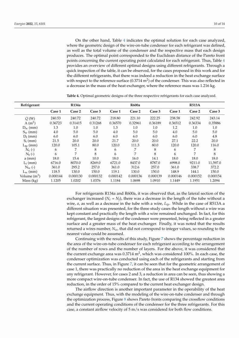
On the other hand, Table 4 indicates the optimal solution for each case analyzed,where the geometric design of the wire-on-tube condenser for each refrigerant was defined,as well as the total volume of the condenser and the respective mass that each designproduces. The optimal point corresponded to the Euclidean distance of the Pareto frontpoints concerning the current operating point calculated for each refrigerant. Thus, Table 4provides an overview of different optimal designs using different refrigerants. Through aquick inspection of the table, it can be observed, for the cases proposed in this work and forthe different refrigerants, that there was indeed a reduction in the heat exchange surfacewith respect to the reference surface (0.3714 m2) of the condenser. This was also reflected ina decrease in the mass of the heat exchanger, where the reference mass was 1.216 kg.
Table 4. Optimal geometric designs of the three respective refrigerants for each case analyzed.
Refrigerant R134a R600a R513A
Case 1 Case 2 Case 3 Case 1 Case 2 Case 3 Case 1 Case 2 Case 3.
Q (W) 240.53 240.72 240.72 218.80 221.10 222.25 238.58 242.92 243.14A (m2) 0.36723 0.31415 0.31268 0.36570 0.32961 0.36189 0.36512 0.36334 0.35886
Dw (mm) 1.3 1.0 1.0 1.3 1.0 1.0 1.2 1.0 1.0Sw (mm) 4.0 5.0 5.0 4.0 5.0 5.0 4.0 5.0 5.0Dt (mm) 6.0 6.0 6.0 6.0 6.0 6.0 6.0 6.0 4.8St (mm) 21.5 20.0 20.0 21.7 20.0 20.0 27.1 22.2 20.0
Ltp (mm) 120.0 105.1 80.0 120.0 111.3 80.0 120.0 120.0 116.0Nc (-) 6 7 8 6 7 8 6 7 8Nf (-) 6 7 8 6 7 8 6 7 8
a (mm) 18.0 15.4 10.0 18.0 16.0 14.1 18.0 18.0 18.0Lt (mm) 6716.0 8070.0 8269.0 6721.0 8437.0 8787.0 6998.0 9211.0 11,597.0Nw (-) 361.0 295.2 257.0 361.0 312.6 257.0 361.0 338.7 372.2
Lw (mm) 118.5 130.0 150.0 119.1 130.0 150.0 148.9 144.1 150.0Volume (m3) 0.000144 0.000130 0.000132 0.000142 0.000136 0.000139 0.000146 0.000152 0.000154
Mass (kg) 1.1205 1.0202 1.0376 1.1184 1.0698 1.0910 1.1449 1.1951 1.2094
For refrigerants R134a and R600a, it was observed that, as the lateral section of theexchanger increased (Nc = Nf), there was a decrease in the length of the tube without awire, a, as well as a decrease in the tube with a wire, Ltp. While in the case of R513A adifferent situation was presented, for the three study cases the length without a wire waskept constant and practically the length with a wire remained unchanged. In fact, for thisrefrigerant, the largest designs of the condenser were presented, being reflected in a greatersurface and a greater mass of the heat exchanger. Finally, it was noted that the resultsreturned a wires number, Nw, that did not correspond to integer values, so rounding to thenearest value could be assumed.
Continuing with the results of this study, Figure 7 shows the percentage reduction inthe area of the wire-on-tube condenser for each refrigerant according to the arrangementof the number of rows and the number of layers. For the above, it was considered thatthe current exchange area was 0.3714 m2, which was considered 100%. In each case, thecondenser optimization was conducted using each of the refrigerants and starting fromthe current surface. Thus, in Figure 7, it can be seen that for the geometric arrangement ofcase 1, there was practically no reduction of the area in the heat exchange equipment forany refrigerant. However, for cases 2 and 3, a reduction in area can be seen, thus showing amore compact wire-on-tube condenser. In fact, the use of R134 showed the greatest areareduction, in the order of 15% compared to the current heat exchanger design.
The airflow direction is another important parameter in the operability of the heatexchange equipment. Thus, with the modeling of the wire-on-tube condenser and throughthe optimization process, Figure 8 shows Pareto fronts comparing the crossflow conditionsand the current operating conditions of the condenser for the three refrigerants. For thiscase, a constant airflow velocity of 5 m/s was considered for both flow conditions.

Energies 2022, 15, 6101 11 of 14
Energies 2022, 15, x FOR PEER REVIEW 11 of 14
Continuing with the results of this study, Figure 7 shows the percentage reduction in
the area of the wire-on-tube condenser for each refrigerant according to the arrangement
of the number of rows and the number of layers. For the above, it was considered that the
current exchange area was 0.3714 m2, which was considered 100%. In each case, the con-
denser optimization was conducted using each of the refrigerants and starting from the
current surface. Thus, in Figure 7, it can be seen that for the geometric arrangement of case
1, there was practically no reduction of the area in the heat exchange equipment for any
refrigerant. However, for cases 2 and 3, a reduction in area can be seen, thus showing a
more compact wire-on-tube condenser. In fact, the use of R134 showed the greatest area
reduction, in the order of 15% compared to the current heat exchanger design.
Figure 7. Reductions of the wire-on-tube condenser area for the use of the three refrigerants.
The airflow direction is another important parameter in the operability of the heat
exchange equipment. Thus, with the modeling of the wire-on-tube condenser and through
the optimization process, Figure 8 shows Pareto fronts comparing the crossflow condi-
tions and the current operating conditions of the condenser for the three refrigerants. For
this case, a constant airflow velocity of 5 m/s was considered for both flow conditions.
Figure 8. Heat transfers for the current and crossflow conditions.
A quick inspection of Figure 8 shows a clear reduction in the heat exchange surface
for the crossflow condition for a defined heat transfer. Considering the optimum point of
each Pareto front for the crossflow with respect to the current condition of the condenser,
it can be deduced that for the case of R134a there were an increase in heat transfer of 1.4%
and a reduction in the area of the 24%. In the case of R600a, an area reduction of 17% was
obtained for a heat transfer increase of 2.3%. Finally, the R513A refrigerant presented a
reduction in the exchange surface of 2.4% and an increase in the heat transfer of 5%.
Figure 7. Reductions of the wire-on-tube condenser area for the use of the three refrigerants.
Energies 2022, 15, x FOR PEER REVIEW 11 of 14
Continuing with the results of this study, Figure 7 shows the percentage reduction in
the area of the wire-on-tube condenser for each refrigerant according to the arrangement
of the number of rows and the number of layers. For the above, it was considered that the
current exchange area was 0.3714 m2, which was considered 100%. In each case, the con-
denser optimization was conducted using each of the refrigerants and starting from the
current surface. Thus, in Figure 7, it can be seen that for the geometric arrangement of case
1, there was practically no reduction of the area in the heat exchange equipment for any
refrigerant. However, for cases 2 and 3, a reduction in area can be seen, thus showing a
more compact wire-on-tube condenser. In fact, the use of R134 showed the greatest area
reduction, in the order of 15% compared to the current heat exchanger design.
Figure 7. Reductions of the wire-on-tube condenser area for the use of the three refrigerants.
The airflow direction is another important parameter in the operability of the heat
exchange equipment. Thus, with the modeling of the wire-on-tube condenser and through
the optimization process, Figure 8 shows Pareto fronts comparing the crossflow condi-
tions and the current operating conditions of the condenser for the three refrigerants. For
this case, a constant airflow velocity of 5 m/s was considered for both flow conditions.
Figure 8. Heat transfers for the current and crossflow conditions.
A quick inspection of Figure 8 shows a clear reduction in the heat exchange surface
for the crossflow condition for a defined heat transfer. Considering the optimum point of
each Pareto front for the crossflow with respect to the current condition of the condenser,
it can be deduced that for the case of R134a there were an increase in heat transfer of 1.4%
and a reduction in the area of the 24%. In the case of R600a, an area reduction of 17% was
obtained for a heat transfer increase of 2.3%. Finally, the R513A refrigerant presented a
reduction in the exchange surface of 2.4% and an increase in the heat transfer of 5%.
Figure 8. Heat transfers for the current and crossflow conditions.
A quick inspection of Figure 8 shows a clear reduction in the heat exchange surfacefor the crossflow condition for a defined heat transfer. Considering the optimum point ofeach Pareto front for the crossflow with respect to the current condition of the condenser, itcan be deduced that for the case of R134a there were an increase in heat transfer of 1.4%and a reduction in the area of the 24%. In the case of R600a, an area reduction of 17% wasobtained for a heat transfer increase of 2.3%. Finally, the R513A refrigerant presented areduction in the exchange surface of 2.4% and an increase in the heat transfer of 5%.
4. Conclusions
In this work, the optimization of a multilayer wire-on-tube condenser was conductedconsidering the maximization of the heat transfer and the reduction of the condenserarea as objective functions. In addition, through the statistical analysis performed for theevaluation and selection of the best algorithm, it was obtained that OMOPSO presentedstatistically better results compared to the NSGAII and MOEAD algorithms.
By using the OMOPSO multi-objective optimization algorithm and evaluating eightgeometric parameters, the Pareto front graphs were obtained for three case studies and forthree refrigerants R134a, R600a, and R513A, obtaining for each case the current operatingconditions and the optimization proposal. Through the optimization process, a considerableimprovement in the design of the multilayer wire-on-tube condenser was obtained usingthe refrigerants evaluated in this work.
Since R600a and R513A refrigerants are considered low GWP alternatives for domesticrefrigeration systems, in this case, the use of R600a presented greater benefits in termsof reduction of the condenser heat exchange area. On the other hand, the operation ofthe wire-on-tube condenser under crossflow conditions considerably improved the heattransfer, thus allowing a greater reduction in the condenser area.
Energies 2022, 15, 6101 12 of 14
Finally, this type of study allows expanding the knowledge of the use of heuristicoptimization algorithms in multi-objective optimization processes for heat exchange equip-ment and helps design engineers or manufacturers to present better, more compact designswith greater heat transfers.
Author Contributions: Conceptualization, Y.H.-A. and J.A.S.-A.; methodology and writing of thepaper, J.M.B.-F. and Y.H.-A.; analysis of the information, J.A.S.-A.; investigation and wring of thepaper, V.P.-G. and F.E.-B.; review and editing, J.M.B.-F., J.A.A.-A. and J.R.-M. All authors have readand agreed to the published version of the manuscript.
Funding: This research received no external funding.
Institutional Review Board Statement: Not applicable.
Informed Consent Statement: Not applicable.
Data Availability Statement: Not applicable.
Acknowledgments: We acknowledge the University of Guanajuato for their sponsorship in therealization of this work.
Conflicts of Interest: The authors declare no conflict of interest.
Nomenclature
a length without wires (mm)A area (m2)CFD computational fluid dynamicsD diameter (mm)FOA Falcon Optimization AlgorithmGWP Global Warming PotentialL length (mm)Ltp length with wire (mm).
m mass flow rate (kg/s)MOEAD Multi-objective Evolutionary Algorithm based on DecompositionMOGA Multi-objective Genetic AlgorithmMOHTS Multi-objective Heat Transfer SearchMOWO Multi-objective Wale OptimizationNc layers number (-)Nf rows number (-)Nw wires number (-)NSGAII Non-dominated Sorting Genetic Algorithm-IINTU number of transfer units (-)OMOPSO Optimized Multi-objective Particle Swarm OptimizationP pressure (bar).
Q heat transfer rate (W)S pitch (mm)T temperature (K)Subscriptsamb ambientair aircond Condensation and condenserdsh desuperheatingin inletout outletr refrigerantsub subcoolingT totalt tubew wire

Energies 2022, 15, 6101 13 of 14
References1. Xie, G.N.; Sundén, B.; Wang, Q.W. Optimization of compact heat exchangers by a genetic algorithm. Appl. Therm. Eng. 2008, 28,
895–906. [CrossRef]2. Lv, J.; Jiang, X.; He, G.; Xiao, W.; Li, S.; Sengupta, D.; El-Halwagi, M.M. Economic and system reliability optimization of heat
exchanger networks using NSGA-II algorithm. Appl. Therm. Eng. 2017, 124, 716–724. [CrossRef]3. Bansal, P.K.; Chin, T.C. Modelling and optimisation of wire-and-tube condenser. Int. J. Refrig. 2003, 26, 601–613. [CrossRef]4. Zhang, Z.; Huang, D.; Zhao, R.; Leng, Y. Effect of airflow field optimization around spiral wire-on-tube condenser on a frost-free
refrigerator performance. Appl. Therm. Eng. 2017, 114, 785–792. [CrossRef]5. Raja, B.D.; Jhala, R.L.; Patel, V. Thermal-hydraulic optimization of plate heat exchanger: A multi-objective approach. Int. J. Therm.
Sci. 2018, 124, 522–535. [CrossRef]6. Imran, M.; Pambudi, N.A.; Farooq, M. Thermal and hydraulic optimization of plate heat exchanger using multi objective genetic
algorithm. Case Stud. Therm. Eng. 2017, 10, 570–578. [CrossRef]7. Kumar, S.D.; Chandramohan, D.; Purushothaman, K.; Sathish, T. Optimal hydraulic and thermal constrain for plate heat
exchanger using multi objective wale optimization. Mater. Today Proc. 2020, 21, 876–881. [CrossRef]8. Sodagar-Abardeh, J.; Ebrahimi-Moghadam, A.; Farzaneh-Gord, M.; Norouzi, A. Optimizing chevron plate heat exchangers based
on the second law of thermodynamics and genetic algorithm. J. Therm. Anal. Calorim. 2020, 139, 3563–3576. [CrossRef]9. Tharakeshwar, T.K.; Seetharamu, K.N.; Prasad, B.D. Multi-objective optimization using bat algorithm for shell and tube heat
exchangers. Appl. Therm. Eng. 2017, 110, 1029–1038. [CrossRef]10. Wang, S.; Xiao, J.; Wang, J.; Jian, G.; Wen, J.; Zhang, Z. Configuration optimization of shell-and-tube heat exchangers with helical
baffles using multi-objective genetic algorithm based on fluid-structure interaction. Int. Commun. Heat Mass Transf. 2017, 85,62–69. [CrossRef]
11. Zarea, H.; Kashkooli, F.M.; Mehryan, A.M.; Saffarian, M.R.; Beherghani, E.N. Optimal design of plate-fin heat exchangers by aBees Algorithm. Appl. Therm. Eng. 2014, 69, 267–277. [CrossRef]
12. Rao, R.V.; Saroj, A. Constrained economic optimization of shell-and-tube heat exchangers using elitist-Jaya algorithm. Energy2017, 128, 785–800. [CrossRef]
13. Mirzaei, M.; Hajabdollahi, H.; Fadakar, H. Multi-objective optimization of shell-and-tube heat exchanger by constructal theory.Appl. Therm. Eng. 2017, 125, 9–19. [CrossRef]
14. Raja, B.D.; Jhala, R.L.; Patel, V. Many-objective optimization of shell and tube heat exchanger. Therm. Sci. Eng. Prog. 2017, 2,87–101. [CrossRef]
15. Dhavle, S.V.; Kulkarni, A.J.; Shastri, A.; Kale, I.R. Design and economic optimization of shell-and-tube heat exchanger usingcohort intelligence algorithm. Neural Comput. Appl. 2018, 30, 111–125. [CrossRef]
16. de Vasconcelos Segundo, E.H.; Mariani, V.C.; dos Santos Coelho, L. Design of heat exchangers using Falcon OptimizationAlgorithm. Appl. Therm. Eng. 2019, 156, 119–144. [CrossRef]
17. Deb, K.; Agrawal, S.; Pratap, A.; Meyarivan, T. A fast elitist non-dominated sorting genetic algorithm for multi-objectiveoptimization: NSGA-II. In Proceedings of the International Conference on Parallel Problem Solving from Nature, Paris, France,18–20 September 2000; Springer: Berlin/Heidelberg, Germany, 2000; pp. 849–858.
18. Sanaye, S.; Hajabdollahi, H. Thermal-economic multi-objective optimization of plate fin heat exchanger using genetic algorithm.Appl. Energy 2010, 87, 1893–1902. [CrossRef]
19. Rodríguez, M.B.R.; Rodríguez, J.L.M.; Fontes, C.H.D.O. Thermo ecological optimization of shell and tube heat exchangers usingNSGA II. Appl. Therm. Eng. 2019, 156, 91–98. [CrossRef]
20. Liu, C.; Bu, W.; Xu, D. Multi-objective shape optimization of a plate-fin heat exchanger using CFD and multi-objective geneticalgorithm. Int. J. Heat Mass Transf. 2017, 111, 65–82. [CrossRef]
21. Sierra, M.R.; Coello, C.A.C. Improving PSO-based multi-objective optimization using crowding, mutation and ∈-dominance. InProceedings of the International Conference on Evolutionary Multi-Criterion Optimization, Guanajuato, Mexico, 9–11 March2005; Springer: Berlin/Heidelberg, Germany, 2005; pp. 505–519.
22. Godínez, A.C.; Espinosa, L.E.M.; Montes, E.M. An experimental comparison of multiobjective algorithms: NSGA-II andOMOPSO. In Proceedings of the 2010 IEEE Electronics, Robotics and Automotive Mechanics Conference, Cuernavaca, Mexico,28 September–1 October 2010; pp. 28–33.
23. Hadka, D.; Reed, P. Diagnostic assessment of search controls and failure modes in many-objective evolutionary optimization.Evol. Comput. 2012, 20, 423–452. [CrossRef]
24. Espindola, R.S.; Boeng, J.; Knabben, F.T.; Hermes, C.J. A new heat transfer correlation for natural draft wire-on-tube condensersfor a broad geometry span. Int. J. Refrig. 2020, 114, 10–18. [CrossRef]
25. Belman-Flores, J.M.; Heredia-Aricapa, Y.; García-Pabón, J.J.; Gallegos-Muñoz, A.; Serrano-Arellano, J.; Pérez-Reguera, C.G. Anapproximate model of a multilayer wire-on-tube condenser operating with R134a and R600a: Experimental validation andparametric analysis. Case Stud. Therm. Eng. 2021, 25, 100927. [CrossRef]
26. Deb, K.; Pratap, A.; Agarwal, S.; Meyarivan, T.A.M.T. A fast and elitist multiobjective genetic algorithm: NSGA-II. IEEE Trans.Evol. Comput. 2002, 6, 182–197. [CrossRef]
27. Reyes-Sierra, M.; Coello, C.A.C. On-line adaptation in multi-objective particle swarm optimization. In Proceedings of the IEEESwarm Intelligence Symposium 2006, Indianapolis, IN, USA, 12–14 May 2006; pp. 12–14.

Energies 2022, 15, 6101 14 of 14
28. Zhang, Q.; Li, H. MOEA/D: A multiobjective evolutionary algorithm based on decomposition. IEEE Trans. Evol. Comput. 2007,11, 712–731. [CrossRef]
29. Benítez, A.; Nebro, A.; García-Nieto, J.; Oregi, I.; Ser, J.D. jMetalPy: A Python framework for multi-objective optimization withmetaheuristics. Swarm Evol. Comput. 2019, 51, 100598. [CrossRef]
30. Python Software Foundation. 2020. Available online: http://www.python.org (accessed on 15 April 2022).
Related Documents