HAL Id: tel-01079786 https://tel.archives-ouvertes.fr/tel-01079786 Submitted on 3 Nov 2014 HAL is a multi-disciplinary open access archive for the deposit and dissemination of sci- entific research documents, whether they are pub- lished or not. The documents may come from teaching and research institutions in France or abroad, or from public or private research centers. L’archive ouverte pluridisciplinaire HAL, est destinée au dépôt et à la diffusion de documents scientifiques de niveau recherche, publiés ou non, émanant des établissements d’enseignement et de recherche français ou étrangers, des laboratoires publics ou privés. Multi-Object modelling of the face Hanan Salam To cite this version: Hanan Salam. Multi-Object modelling of the face. Other. Supélec, 2013. English. NNT : 2013SUPL0035. tel-01079786

Welcome message from author
This document is posted to help you gain knowledge. Please leave a comment to let me know what you think about it! Share it to your friends and learn new things together.
Transcript

HAL Id: tel-01079786https://tel.archives-ouvertes.fr/tel-01079786
Submitted on 3 Nov 2014
HAL is a multi-disciplinary open accessarchive for the deposit and dissemination of sci-entific research documents, whether they are pub-lished or not. The documents may come fromteaching and research institutions in France orabroad, or from public or private research centers.
L’archive ouverte pluridisciplinaire HAL, estdestinée au dépôt et à la diffusion de documentsscientifiques de niveau recherche, publiés ou non,émanant des établissements d’enseignement et derecherche français ou étrangers, des laboratoirespublics ou privés.
Multi-Object modelling of the faceHanan Salam
To cite this version:Hanan Salam. Multi-Object modelling of the face. Other. Supélec, 2013. English. �NNT :2013SUPL0035�. �tel-01079786�

N° d’ordre : 2013-35-TH
SUPELEC
Ecole Doctorale MATISSE
« Mathématiques, Télécommunications, Informatique, Signal, Systèmes Electroniques »
THÈSE DE DOCTORAT
DOMAINE : STIC Spécialité : Traitement du signal et telecommunication
Soutenue le 20/12/2013
par :
Hanan SALAM
Modélisation Multi-Objet du visage Directeur de thèse : Renaud Seguier Professeur (IETR) Composition du jury : Président du jury : Lionel PREVOST Professeur (LAMIA) Rapporteurs : Saidi BOUAKAZ Professeur (LIRIS) Jean-Claude MARTIN Professeur (LIMSI) Examinateurs : Piere-Yves COULON Professeur (Gipsa-Lab)


Abstract
The work in this thesis deals with the problem of face modeling for the purpose offacial analysis. Facial modeling was used to achieve gaze and blink detection and emotionrecognition.
In the first part of this thesis, we proposed the Multi-Object Facial Actions ActiveAppearance Model. The specificity of the proposed model is that different parts of theface are treated as separate objects and eye movements (gaze and blink) are extrinsicallyparameterized. Starting from a learning database that contains no variations in gaze orblink, the model is able to follow the movements of the eyeball and eyelids, which increasesthe robustness of active appearance models (AAM) by restricting the amount of variationin the learning base.
The second part of the thesis concerns the use of face modeling in the context of ex-pression and emotion recognition. First we have proposed a system for the recognitionof facial expressions in the form of Action Units (AU). The proposed system is based onthe combination of Local Gabor Binary Pattern Histograms (appearance features) andAAMs (hybrid features: appearance and geometry) using Multi-Kernel Support MachineVectors. Our contribution concerned mainly the extraction of AAM features. The AUs todetect concerned the upper and lower part of the face. Thus, we have opted for the use oflocal models to extract these features. Results have demonstrated that the combinationof AAM with the LGBP appearance features has led to ameliorate the results of recog-nition. This system was evaluated in FERA 2011, an international challenge for emotionrecognition of which our team have took the first place.
The second system concerns the multi-modal recognition of four continuously valuedaffective dimensions: arousal, valence, power and expectancy. We have proposed a systemthat fuses audio, context and visual features and gives as output the four emotional dimen-sions. The visual features are in the form of facial expressions. More precisely, we havefound that the smile is a relevant cue for the detection of the aforementioned dimensions.To detect this feature, AAM is used to delineate the face. We contribute at this stage ofthe system to find the precise localization of the facial features. Accordingly, we proposethe Multi-Local AAM. This model combines extrinsically a global model of the face anda local one of the mouth through the computation of projection errors on the same globalAAM. The proposed system was evaluated in the context of AVEC 2012 challenge andour team got the second place with very close results to those who came in the first place.


To my parents...The source of my pride
. . . úG.�
� @ �ð ú
��×� @ ú
�Í@ �
úG.�à@ �Pñ
�m�A �Ò��J K @ A ��ÜØ� Q
���» @ A �Ò�º��J��K. @ � ú
G�ñ�ºK.� '
��è �Pñ�m�úæ�
��K @. . éJ�Ê �« A
�K� @ A �Ó ú
�Í@ �
��IÊ �� �ð A �Ü�Ï A �Ò
�»B
�ñ�Ë


Acknowledgments
The work in this thesis is the result of my research and exchange with several personsduring the simultaneously long and short past three years in Supelec, team SCEE, IETR.These years were tremendously enriching together at the professional and at the personallevels. The first person I would like to thank is my thesis supervisor Renaud SEGUIER.He has guided me through the work of this thesis, given me advice and encouragementsto continue. I am really grateful for his moral support, for not stressing me at all, forbeing patient and understanding especially when I had so much questions, and for makingme believe more in myself and my work. Working with him has enriched me by lessonsabout success, positive thinking, taking risks, moving forward and enthusiasm. It is agreat pleasure to work with such a person. I personally think he is the best supervisoranyone can ever have.
I am also thankful for Christophe MOY for being the director of my thesis for two yearsand for his readiness to help me through the work of this thesis. His encouragementand advice have helped me a lot especially his advice about the writing of this repport. Iam really grateful for his kindness and support and it was a pleasure to be directed by him.
I also want to thank Nicolas STOIBER for the several scientific meetings of which wehave exchanged ideas. I am thankful to him for responding to my questions and for hisvaluable remarks that have been a source for advancing this work.
I would also like to pay my sincere gratitude to Jacques Palicot, the director of the teamSCEE. His advice has helped a lot especially before my final presentation.
I think SCEE is a really comfortable place to work in because of its friendly work envi-ronment. Everybody is welcoming and friendly. I thank professors Yves LOUET, DanielLE GUENEC and Christophe MOY for being friendly and welcoming. I thank the ad-ministration of Supelec for being very helpful and kind. I equally thank the 5050 teamof Supelec for responding fast to the several technical obstacles that my computer wentthrough during this thesis.
I would like to thank Professor Saida BOUAKAZ, Universite Claude Bernard Lyon1

(LIRIS) and Jean-Claude MARTIN, Universite Paris Sud (LIMSI)for accepting to be therapporters of my thesis. I also want to thank the other members of the jury ProfessorsLionel PREVOST, Universite des Antilles et de la Guyane (LAMIA), and Pierre-YvesCOULON, Grenoble-INP (Gipsa-Lab) for being present to judge my research work in thisthesis.
I am really thankful to the staff of Dynamixyz. Thanks to Gaspard Breton for per-mitting me to work at Dynamixyz when Supelec was closed and thanks to all the othersat Dynamixyz for welcoming me in their workplace.
I want to say thank you to my friends and colleagues Ziad, Oussama, Caroline, Xi guang,Lamarana, Abel, Samba, Marwa, Jerome, Catherine, Salma, Patricia, Wassim, Vincent.They have all supported me during hard periods of the thesis. Thank you Caroline andMarwa for being so supportive in some hard times. Thank you both for being ”StudyPartners” in the ”No-Motivation” days. A big thanks goes also to my friend Oussamafor making the work place more fun. The breaks we did were very helpful to work moreefficiently.
A special thanks goes to my compatriots, friends and sometimes roommates: Farah, Ri-ham, Lama and Hussien. Without them it would have been so much harder to go throughthese years. I am thankful for their support and for being there to fill out the leisuretime. I would not forget Nour Soleil, my friend since the first year of university. She hasmassively supported and encouraged me to work especially during the period of writingmy thesis.
A particular thanks goes to Professor Mohamed ZOAETER, the former dean of the fac-ulty of engineering at the Lebanese university, for opening the doors between the Lebaneseuniversity and the universities of France. In my opinion, his diligence has a lot contributedin the advancement of the research in Lebanon.
The warmest gratitude goes to my beloved parents, Ali and Salma, for their continu-ous emotional support. Thank you father for letting me pursue my ambitions with somuch love and support. Thank you mother for your kindliness and prayers. I thank myfour brothers for their humor which made the journey of my studies lighter and moreamusing even if it was from a distance. Without my family my success would not havebeen possible.
Hanan SALAM

Contents
1 Face Modeling: A state of art 7
1.1 Analysis models . . . . . . . . . . . . . . . . . . . . . . . . . . . . . . . . . . 8
1.1.1 Hand-crafted models (manual models) . . . . . . . . . . . . . . . . . 10
1.1.2 Active contours . . . . . . . . . . . . . . . . . . . . . . . . . . . . . . 10
1.1.3 Constrained local appearance models . . . . . . . . . . . . . . . . . . 13
1.1.4 3D feature-based model analysis . . . . . . . . . . . . . . . . . . . . 15
1.1.5 Discussion . . . . . . . . . . . . . . . . . . . . . . . . . . . . . . . . . 16
1.2 Synthesis models . . . . . . . . . . . . . . . . . . . . . . . . . . . . . . . . . 16
1.2.1 Blend shapes models . . . . . . . . . . . . . . . . . . . . . . . . . . . 16
1.2.2 Skeletal-based models . . . . . . . . . . . . . . . . . . . . . . . . . . 17
1.2.3 Parameter-based models . . . . . . . . . . . . . . . . . . . . . . . . . 19
1.2.4 Discussion . . . . . . . . . . . . . . . . . . . . . . . . . . . . . . . . . 23
1.3 Analysis-by-Synthesis models . . . . . . . . . . . . . . . . . . . . . . . . . . 23
1.3.1 Statistical models . . . . . . . . . . . . . . . . . . . . . . . . . . . . . 24
1.3.2 Manual Models . . . . . . . . . . . . . . . . . . . . . . . . . . . . . . 26
1.3.3 Discussion . . . . . . . . . . . . . . . . . . . . . . . . . . . . . . . . . 29
1.4 Gaze and blink detection: a state of the art . . . . . . . . . . . . . . . . . . 30
1.4.1 Gaze tracking . . . . . . . . . . . . . . . . . . . . . . . . . . . . . . . 30
1.4.2 Blink detection . . . . . . . . . . . . . . . . . . . . . . . . . . . . . . 34
1.5 Conclusion . . . . . . . . . . . . . . . . . . . . . . . . . . . . . . . . . . . . 37
2 Active Appearance Models: Formulation and Limitations 39
2.1 Active Appearance Model creation . . . . . . . . . . . . . . . . . . . . . . . 40
2.1.1 Shape modeling . . . . . . . . . . . . . . . . . . . . . . . . . . . . . . 40
2.1.2 Texture modeling . . . . . . . . . . . . . . . . . . . . . . . . . . . . . 42
2.1.3 Appearance modeling . . . . . . . . . . . . . . . . . . . . . . . . . . 44
2.2 AAM fitting . . . . . . . . . . . . . . . . . . . . . . . . . . . . . . . . . . . . 45
2.3 Challenges, Limitations and extensions of AAMs . . . . . . . . . . . . . . . 46
2.3.1 Generalization . . . . . . . . . . . . . . . . . . . . . . . . . . . . . . 47
2.3.2 Non-decoupled parameters . . . . . . . . . . . . . . . . . . . . . . . . 51
2.4 Conclusion . . . . . . . . . . . . . . . . . . . . . . . . . . . . . . . . . . . . 54

CONTENTS
3 A multi-object facial actions AAM 553.1 Introduction of the proposed model . . . . . . . . . . . . . . . . . . . . . . . 56
3.1.1 Facial Action AAM . . . . . . . . . . . . . . . . . . . . . . . . . . . 593.1.2 Multi-Object AAM . . . . . . . . . . . . . . . . . . . . . . . . . . . . 633.1.3 Multi-Objective modeling: general idea . . . . . . . . . . . . . . . . 71
3.2 Tests and Results . . . . . . . . . . . . . . . . . . . . . . . . . . . . . . . . . 753.2.1 Blink detection . . . . . . . . . . . . . . . . . . . . . . . . . . . . . . 763.2.2 Gaze detection . . . . . . . . . . . . . . . . . . . . . . . . . . . . . . 83
3.3 Conclusion . . . . . . . . . . . . . . . . . . . . . . . . . . . . . . . . . . . . 99
4 Face modeling for emotion recognition 1014.1 The Facial Expression Recognition and Analysis Challenge . . . . . . . . . 102
4.1.1 System overview . . . . . . . . . . . . . . . . . . . . . . . . . . . . . 1044.1.2 Active Appearance Models coefficients . . . . . . . . . . . . . . . . . 1074.1.3 Results . . . . . . . . . . . . . . . . . . . . . . . . . . . . . . . . . . 109
4.2 The Audio/Visual Emotion Challenge . . . . . . . . . . . . . . . . . . . . . 1164.2.1 Global system . . . . . . . . . . . . . . . . . . . . . . . . . . . . . . . 1174.2.2 Facial Features detection: The Multi-model AAM . . . . . . . . . . 1214.2.3 Emotion detection results . . . . . . . . . . . . . . . . . . . . . . . . 126
4.3 Conclusion . . . . . . . . . . . . . . . . . . . . . . . . . . . . . . . . . . . . 128
Conclusion 131

List of Figures
1 The different cues of non-verbal communication . . . . . . . . . . . . . . . . 22 Automatic face analysis structure . . . . . . . . . . . . . . . . . . . . . . . . 3
1.1 Flow chart of the state-of-the-art classification . . . . . . . . . . . . . . . . 91.2 A virtual character’s blend shapes . . . . . . . . . . . . . . . . . . . . . . . 161.3 An example of skeletal animation of the face . . . . . . . . . . . . . . . . . 181.4 An example of rigging the eyeball using the ”blender” animation software . 181.5 Rational Free Form Deformation . . . . . . . . . . . . . . . . . . . . . . . . 221.6 Analysis-by-synthesis loop . . . . . . . . . . . . . . . . . . . . . . . . . . . . 241.7 Candide model with 9 Facial actions (from [Oro07]) . . . . . . . . . . . . . 271.8 The effect of changing shape parameters of Candide . . . . . . . . . . . . . 281.9 The effect of changing 4 action parameters of Candide . . . . . . . . . . . . 281.10 Flow chart of the state-of-the-art classification of gaze tracking . . . . . . . 301.11 Flow chart of the state-of-the-art classification of blink detection . . . . . . 35
2.1 Active Appearance Models steps . . . . . . . . . . . . . . . . . . . . . . . . 402.2 AAM creation . . . . . . . . . . . . . . . . . . . . . . . . . . . . . . . . . . . 412.3 Active Appearance Models Fitting . . . . . . . . . . . . . . . . . . . . . . . 432.4 AAM training process . . . . . . . . . . . . . . . . . . . . . . . . . . . . . . 442.5 Limitations and Extensions of AAM . . . . . . . . . . . . . . . . . . . . . . 472.6 Gradient orientation maps of [TAiMZP12] . . . . . . . . . . . . . . . . . . . 48
3.1 Facial actions representation of the face . . . . . . . . . . . . . . . . . . . . 573.2 Multi-Object representation of the face . . . . . . . . . . . . . . . . . . . . . 573.3 Identification of the principle axes of the displacement of the facial land-
marks of one subject . . . . . . . . . . . . . . . . . . . . . . . . . . . . . . . 593.4 Variation of the landmarks for the left and right eyebrows of one subject
during the eyebrow motions . . . . . . . . . . . . . . . . . . . . . . . . . . . 603.5 Variation of the landmarks for the left and right eyes of one subject during
blinking. The principle components of every landmark are overlaid overthe cloud of points of each of these landmarks. The red stars represent themean of each of the landmarks. . . . . . . . . . . . . . . . . . . . . . . . . 61
3.6 Illustration of modeling the eyeball as a sphere in computer graphics . . . . 64

LIST OF FIGURES
3.7 Multi-texture idea illustration . . . . . . . . . . . . . . . . . . . . . . . . . . 65
3.8 An example of a training iris image before and after processing . . . . . . . 66
3.9 Discontinuity between the eye skin object and the iris object when mergingthem . . . . . . . . . . . . . . . . . . . . . . . . . . . . . . . . . . . . . . . . 67
3.10 Iris border pixels affected by the application of the filter . . . . . . . . . . . 68
3.11 Error Calculation at one iteration . . . . . . . . . . . . . . . . . . . . . . . . 69
3.12 Illustration of modeling the iris as a part of a sphere . . . . . . . . . . . . . 70
3.13 Barycentric coordinates . . . . . . . . . . . . . . . . . . . . . . . . . . . . . 70
3.14 Global system overview . . . . . . . . . . . . . . . . . . . . . . . . . . . . . 73
3.15 Double logistic function . . . . . . . . . . . . . . . . . . . . . . . . . . . . . 74
3.16 A chromosome of the genetic algorithm . . . . . . . . . . . . . . . . . . . . 75
3.17 Comparison between the GTE of different eye models . . . . . . . . . . . . 77
3.18 Comparison between different eye models with a blinking parameter . . . . 79
3.19 GTE eyelids . . . . . . . . . . . . . . . . . . . . . . . . . . . . . . . . . . . . 81
3.20 Results of the Face blink model on Database 1 . . . . . . . . . . . . . . . . 82
3.21 Ground Truth Error of the Face Blink model, testing on the PG database . 83
3.22 Results of the Face Blink model in generalization . . . . . . . . . . . . . . . 84
3.23 Visual result showing comparison between the Face blink model with andwithout a hole . . . . . . . . . . . . . . . . . . . . . . . . . . . . . . . . . . 85
3.24 Comparison between with and without hole eye models . . . . . . . . . . . 87
3.25 Qualitative comparison of eyelids model with and without hole . . . . . . . 88
3.26 GTEeyelid vs. GTEiris sorted in descending order . . . . . . . . . . . . . . . 88
3.27 Comparison between different options of GA . . . . . . . . . . . . . . . . . 90
3.28 Comparison between different optimizations . . . . . . . . . . . . . . . . . . 92
3.29 MOAAM vs. SOAAM . . . . . . . . . . . . . . . . . . . . . . . . . . . . . . 93
3.30 Set of iris textures used to train the iris model . . . . . . . . . . . . . . . . 94
3.31 Annotations to obtain the head pose model and the corresponding meantexture . . . . . . . . . . . . . . . . . . . . . . . . . . . . . . . . . . . . . . . 95
3.32 3D MT-AAM vs. 2D MT-AAM vs. Double Eyes AAM . . . . . . . . . . . 96
3.33 Qualitative comparison between the 2D multi-texture approach and theDE-AAM approach . . . . . . . . . . . . . . . . . . . . . . . . . . . . . . . . 97
3.34 Qualitative comparison between the 3D MT-AAM and the 2D MT-AAM . 97
3.35 Comparison of the 3D MT-AAM method to that of [HSL11] . . . . . . . . . 99
4.1 The Action Units to be detected for the FERA 2011 challenge . . . . . . . . 103
4.2 Examples of some images of the GEMEP-FERA dataset . . . . . . . . . . . 104
4.3 Global system of AU detection . . . . . . . . . . . . . . . . . . . . . . . . . 105
4.4 Local Gabor Binary Pattern histograms computation . . . . . . . . . . . . . 106
4.5 Landmarks for the eyes and mouth models . . . . . . . . . . . . . . . . . . . 108
4.6 Mean texture of the global skin model . . . . . . . . . . . . . . . . . . . . . 109
4.7 AAM local models results on some test images showing successful eyes andmouth segmentation . . . . . . . . . . . . . . . . . . . . . . . . . . . . . . . 111

LIST OF FIGURES
4.8 AAM global skin model results on some test images showing successful eyesand mouth segmentation . . . . . . . . . . . . . . . . . . . . . . . . . . . . . 111
4.9 FERA AU sub-challenge official F1 results of all participants . . . . . . . . 1144.10 FERA emotion sub-challenge official F1 results of all participants . . . . . . 1154.11 Examples of the SEMAINE database . . . . . . . . . . . . . . . . . . . . . . 1164.12 Overall view of the proposed emotion detection method . . . . . . . . . . . 1174.13 Sources of the relevant features . . . . . . . . . . . . . . . . . . . . . . . . . 1184.14 Trajectory of one subject’s smile in the person-independent organized ex-
pression space . . . . . . . . . . . . . . . . . . . . . . . . . . . . . . . . . . . 1204.15 Example of person-independent Multi-Model AAM (MM-AAM) . . . . . . . 1224.16 Mean models of the GF-AAM and the LM-AAM . . . . . . . . . . . . . . . 1234.17 An example of an image where neither the GF-AAM nor the LM-AAM
succeed to converge . . . . . . . . . . . . . . . . . . . . . . . . . . . . . . . . 1244.18 Comparison between the GTE of the Multi-Model AAM and the Global
AAM . . . . . . . . . . . . . . . . . . . . . . . . . . . . . . . . . . . . . . . . 1264.19 Comparison between the GF-AAM and the MM-AAM on one sequence of
the test database . . . . . . . . . . . . . . . . . . . . . . . . . . . . . . . . . 1274.20 Example of the MM-AAM in the case where the algorithm chooses the
GF-AAM rather than the combination of the GF-AAM and the LM-AAM . 1284.21 Position of our team (Supelec-Dynamixyz-MinesTelecom) with respect to
the position of the other teams in the AVEC 2012 challenge . . . . . . . . . 129

LIST OF FIGURES

List of Tables
1.1 AUV10 of Candide model . . . . . . . . . . . . . . . . . . . . . . . . . . . . 27
3.1 Summary of the training and testing images used in the different experiments 763.2 Summary of the different eye blink models with different optimizations and
configurations . . . . . . . . . . . . . . . . . . . . . . . . . . . . . . . . . . . 773.3 Comparison of the computation time for the different options of GA . . . . 913.4 Comparison of the computation time of the different optimizations with the
best GA options . . . . . . . . . . . . . . . . . . . . . . . . . . . . . . . . . 92
4.1 2AFC scores on the GEMEP-FERA test dataset using different coefficients 1104.2 Our team’s emotion recognition classification rates on the testing database 1154.3 Results comparing our emotion recognition system to the winner of the
challenge . . . . . . . . . . . . . . . . . . . . . . . . . . . . . . . . . . . . . . 128

LIST OF TABLES

Introduction
The human face – in repose and in movement, at the moment of death as inlife, in silence and in speech, when seen or sensed from within, in actuality oras represented in art or recorded by the camera – is a commanding, complicated,and at times confusing source of information.
– P. Ekman, W. Friesen, and P. Ellsworth, 1972, p.1
Context and Motivation
Human-Human Interaction
Humans usually communicate with each others through two forms: verbal and non-verbal communications. Verbal communication is communicating through spoken wordswhereas non-verbal communication is communicating through exchanging visual and vocalwordless cues. Figure 1 illustrates the different cues of non-verbal communication. Thesecues can be face-related (facial expression, head pose and eye contact), speech-related(volume, pitch, tonality, etc. . . ) or body-related (gestures and touch, body language orposture, etc. . . ).
Albert Mehrabian [MW67], a pioneer researcher of body language, has stated that ina face-to-face communication, 55% of human communication is visual whereas 38% isvocal (speech tone, pitch, volume. . . ) and only 7% is verbal. The face, therefore, canbe considered as the most powerful cue of nonverbal communication. Very importantmessages are encoded in our facial expressions, and during our daily lives, we concurrentlydecode the facial messages encoded in the faces of others. In the simplest interaction, theface is the gravity of our attention. We analyze it to read information that gives us cluesabout the person’s identity, age, emotions, intentions, attraction and even personality.
”The Eyes are the window to the soul”, a very famous English proverb, demonstratesone very important feature of the face: the eye. This feature with its actions that canbe grouped into saccades, fixations, blinking and winking carry information about theperson’s intentions, thinking and interior emotions. Moreover, the eyes language is knownamong all cultures where people communicate with their eyes to send messages to each
1

2 INTRODUCTION
������������� ��������
������� ��
���������������������
�������������� ��
��� ������ ��
��� �� �����������������
������
����
�� ����
����
��� �� ������� ���
��� � ���
���������
��� �!������ �
������������
� �������
"������� #����
�� ������������� ���
����� � �� �����
"�������
���� ��
�����
$���� ��� ����� � ���
�������������� ��
�� ��
������ �� %���������
Figure 1: The different cues of non-verbal communication
other. For instance, staring might mean attraction and rolling eyes means dislike of theother’s speech.
Human-Computer Interaction
Indeed the way that people use machines is of key importance. The most sig-nificant advances in computer science will be those facilitating this interaction.
– T. Winograd and F. Flores, Understanding Computers and Cognition 1986, p.1371
With time, the need for Human Computer Interaction (HCI) is increasing more andmore. Computers had passed from being a completion to ones life to being a necessity.In addition, HCI had grouped multi-disciplinary fields ranging from psychological andmedical to entertainment fields.
For a long time, interacting with computers was done through the mouse and thekeyboard. However, this does not seem enough. Interaction with computers happens nowin our daily lives through the use of our laptops, our tactile phones and tablets and the

3
need for other ways of interaction is mandatory. A recent direction is the integration offace and eyes information as an alternative.
When it comes to Human-Human Interaction (HHI), the task of understanding othersby analyzing their faces or eyes is straightforward. Our minds are used to such analysis.In contrary, when it comes to Human Computer Interaction (HCI), arriving at communi-cating with the computer in a similar manner as in HHI is indeed difficult. The ultimatedream is a human-computer interaction that resembles a human-human interaction. Thatis, a multi-modal verbal and non verbal communication.
This dream carries us towards the field of automatic face processing. The latter consistsof two directions: automatic facial analysis and facial synthesis. In order to arrive atinteracting with computers in a similar way to interacting with humans, computers shouldbe able to analyze faces similar to the analysis of humans and to synthesize facial gesturesand expressions the most realistically possible. This includes the ability of the computerto understand the person’s intentions, emotions and behavior and reproduce them.
Problem Statement
Automatic face analysis
����������
������
����������
����������
���� �������
��������
����������
��������
����������
� ��������
����������
��������������
����
����������
�����������
����������
���������
������������
����������
����
�������� ����������
Figure 2: Automatic face analysis structure
The task of automatic face analysis is indeed a complex and difficult one. The reason isthat individuals faces have different physiognomies. The person’s age, gender, ethnicity,facial hair, make up, and occlusions due to hair and glasses, all play a significant role inestablishing the difference in appearance among individuals. In addition, the variability

4 INTRODUCTION
in head pose and illuminations conditions makes the task of automatic face analysis moreand more difficult.
When we speak about automatic facial analysis, three levels are faced: The level ofdefinition, the level of recognition and that of application. Figure 2 depicts these threelevels.
– The level of definition and this includes face detection and facial features detection.Face detection is detecting the location of the face inside the image. Facial featuresdetection can be done in two forms: detecting high level or low level information.The former is finding the precise locations of the traits of the face which includes theeyes, mouth, eyebrows and chin. The latter is detecting image information such asedges, color, or intensity.
– The level of recognition and this includes the mapping of the extracted informationduring facial definition to more concrete information. This information can be in theform of face recognition, expression recognition, facial gestures recognition or gazedetection.
– The level of application, this means the integration of the automatic face analysissystems in different domains of Human Computer Interaction applications. For ex-ample, these can be integrated in physiognomy (relationship between facial featuresand personality traits), security systems, clinical psychology and psychiatry, biomed-ical applications, lip reading to assist the speech recognition in noisy environments,low bit rate video coding of the face for telecommunication, avatar systems, andentertainment.
Among these three levels, this thesis main contributions are situated in the first twolevels, that is the levels of definition and that of recognition. We are mainly concernedin the face modeling rubric and the use of this modeling for emotion and expressionrecognition tasks.
Face Modeling
In order to define the face and extract its features, a face model should be implemented.This model should be able to deal with the aforementioned constraints that the face issubjected to during the automatic face analysis. For instance, it should be robust to vari-abilities between the appearances of different faces, due to lighting conditions, imagingconditions, makeup, the presence or not of several factors such as eyeglasses, hair, mus-tache, beard, etc. The same face model should be able to account also for changes due tovariable head pose orientation and facial actions including facial expressions.
Active Appearance Models (AAM) [CET98b] are statistical tools that are used to modelthe face shape and appearance. Starting from a set of learning examples, these models areable to find a set of parameters describing the face shape and appearance. Such modelshad proved to be very efficient in modeling faces. They belong to the class of Analysis-by-Synthesis models that find the optimal vector of parameters through the minimization ofthe difference between a synthesized image by the model and the real image. Such models

5
present drawbacks concerning the ability to generalize to new data that are not presentin the learning database and parameters that are not well-defined.
Thesis objectives
The objective of this thesis is to make an advance in face modeling which can beused in face analysis in the context of HCI and automatic human interpretation. Theimplemented methods would facilitate multi-modal non-verbal communication betweenhumans and computers.
The first part of this thesis concentrated on face modeling through the implementationof possible solutions to solve for the limitations of AAM. Such solutions have led to theconception of a system that is capable of analyzing eye motions, specifically eye gaze andblinking of which are known to be very important channels of non-verbal communicationbetween humans.
The second part of this thesis have concentrated on the application of face modeling forexpression and emotion recognition. For this we have participated in two major challengesin the context of a 3D immersion ANR project based on emotional interaction (IMMEMO):The first ”Facial Expression Recognition and Analysis Challenge (FERA 2011)” in col-laboration with the Institut des Systemes Intelligents et de Robotique (ISIR), Universityof Pierre and Marie Curie and LAMIA, University of the West Indies and Guiana. Thischallenge is about detecting expressions in videos in the form of Action Units or discreteexpressions. The second ”International Audio / Visual Emotion Challenge and Work-shop (AVEC 2012)” in collaboration with Laboratoire Traitement et Communication del’Information (LTCI), Telecom ParisTech and the society Dynamixyz, Rennes. It presentsa platform for combining different modalities, mainly audio and visual for the purpose ofemotion recognition. Such combination resembles the real nature of non-verbal communi-cation.
The purpose of these challenges is to advance expression and emotion recognition toprocess data with naturalistic behavior in large volumes that are not segmented or pro-totypical which is the type of data that HCI would face in the implementation of realapplications. Another objective is providing a common database for researchers to com-pare their systems.
Thesis outline and contributions
The chapters of this thesis expose how we contribute to face modeling using ActiveAppearance Models and how we employ the proposed model into a gaze detection sys-tem. In addition, they show our contributions in two grand challenges for expression andmultimodal emotion recognition.
As face modeling is a fundamental rubric for both facial analysis and facial synthesis,we present in chapter 1 a state of the art on both axes. Section 1.1 is dedicated to reviewthe previous work in the analysis domain and section 1.2 reviews those in the synthesis

6 INTRODUCTION
while focusing on facial deformation modeling and synthesis. Section 1.3 reviews methodsthat are based on an analysis-by-synthesis loop. A state of the art on the subjects of gazeand blink detection is included in this chapter in section 1.4.
In chapter 2, we present the theoretical background of the basic Active AppearanceModels [CET98b] in addition to the difficulties and limitations encountered by this classicalformulation.
Chapter 3 represents the first and main contribution of this thesis. We present a newactive appearance face model that uses ideas from the computer graphics domain. Itcombines benefits of statistical models and interpretable parameterizations of geometricmodels. It deals with the face as an aggregation of separate objects. These objects are re-lated to each other through a multi-objective optimization framework. The resulting modelcontributes to Active Appearance Models by restricting images in the facial database.
Chapter 4 presents our contributions in two recognition systems through our participa-tion in two grand challenges: The Facial Expression Recognition and Analysis Challenge(FERA 2011) and the Audio/Visual Emotion Challenge (AVEC 2012).

Chapter 1
Face Modeling: A state of art
Sommaire
1.1 Analysis models . . . . . . . . . . . . . . . . . . . . . . . . . . . . 8
1.1.1 Hand-crafted models (manual models) . . . . . . . . . . . . . . . 10
1.1.2 Active contours . . . . . . . . . . . . . . . . . . . . . . . . . . . . 10
1.1.2.1 Snakes . . . . . . . . . . . . . . . . . . . . . . . . . . . 10
1.1.2.2 Active shape models . . . . . . . . . . . . . . . . . . . . 11
1.1.3 Constrained local appearance models . . . . . . . . . . . . . . . . 13
1.1.3.1 Constrained Local Models . . . . . . . . . . . . . . . . . 13
1.1.3.2 Part-based models . . . . . . . . . . . . . . . . . . . . . 13
1.1.3.3 Face Graphs . . . . . . . . . . . . . . . . . . . . . . . . 14
1.1.4 3D feature-based model analysis . . . . . . . . . . . . . . . . . . 15
1.1.5 Discussion . . . . . . . . . . . . . . . . . . . . . . . . . . . . . . . 16
1.2 Synthesis models . . . . . . . . . . . . . . . . . . . . . . . . . . . . 16
1.2.1 Blend shapes models . . . . . . . . . . . . . . . . . . . . . . . . . 16
1.2.2 Skeletal-based models . . . . . . . . . . . . . . . . . . . . . . . . 17
1.2.3 Parameter-based models . . . . . . . . . . . . . . . . . . . . . . . 19
1.2.3.1 Pseudo-muscles geometric models . . . . . . . . . . . . 19
1.2.3.2 Physically-based Muscle models . . . . . . . . . . . . . 23
1.2.4 Discussion . . . . . . . . . . . . . . . . . . . . . . . . . . . . . . . 23
1.3 Analysis-by-Synthesis models . . . . . . . . . . . . . . . . . . . . 23
1.3.1 Statistical models . . . . . . . . . . . . . . . . . . . . . . . . . . . 24
1.3.1.1 EigenFaces . . . . . . . . . . . . . . . . . . . . . . . . . 24
1.3.1.2 Active Blobs . . . . . . . . . . . . . . . . . . . . . . . . 24
1.3.1.3 3D Morphable models . . . . . . . . . . . . . . . . . . . 25
1.3.1.4 Active Appearance Models (AAM) . . . . . . . . . . . . 26
1.3.2 Manual Models . . . . . . . . . . . . . . . . . . . . . . . . . . . . 26
1.3.3 Discussion . . . . . . . . . . . . . . . . . . . . . . . . . . . . . . . 29
1.4 Gaze and blink detection: a state of the art . . . . . . . . . . . 30
7

8 CHAPTER 1. FACE MODELING: A STATE OF ART
1.4.1 Gaze tracking . . . . . . . . . . . . . . . . . . . . . . . . . . . . . 30
1.4.1.1 IR methods . . . . . . . . . . . . . . . . . . . . . . . . . 31
1.4.1.2 Image based passive approaches . . . . . . . . . . . . . 31
1.4.1.3 Synthesis based . . . . . . . . . . . . . . . . . . . . . . 32
1.4.1.4 Head pose in gaze detection . . . . . . . . . . . . . . . . 33
1.4.2 Blink detection . . . . . . . . . . . . . . . . . . . . . . . . . . . . 34
1.4.2.1 Feature based methods . . . . . . . . . . . . . . . . . . 34
1.4.2.2 State-based methods . . . . . . . . . . . . . . . . . . . . 35
1.4.2.3 Motion-based methods . . . . . . . . . . . . . . . . . . 36
1.4.2.4 Parameter-based methods . . . . . . . . . . . . . . . . . 36
1.5 Conclusion . . . . . . . . . . . . . . . . . . . . . . . . . . . . . . . 37
Modeling faces has took a great portion of research in the fields of Computer Graphicsand Computer Vision. These two fields use face modeling, each in its own way. InComputer Graphics, face modeling is essential for facial synthesis and animation. InComputer Vision, modeling the face and its deformations serves at the automatic analysisof faces.
Even though these two fields intersect in the necessity of realistic modeling of the face,however they remain two separate fields that have their own techniques and associateddifficulties. In this chapter, we explore the state-of-the-art methods in face modeling inboth domains: Synthesis and Analysis of human faces. The reason is that we would liketo explore the modeling techniques of both fields, make a link between them and see if wecan bring ideas from one field to another.¡
Thus, we choose to classify the state-of-the-art in face modeling according to the fieldof application: Analysis, Synthesis and Analysis-by-Synthesis. The Analysis methods arethe set of techniques that are used for the purpose of facial analysis, they are not ableto synthesize faces or their deformations. The output is the detected facial landmarksrepresenting the shape of the face in question. The synthesis methods are those that areused in the field of computer graphics for the purpose of creating and animating faces.Finally the Analysis-by-Synthesis are those that analyze the face through an analysis-by-synthesis loop. Such models are able to both analyze and synthesize faces. The followingsections resume the different face models present in the literature and figure 1.1 depictsthe flow chart of the classification of the different methods of the state of art.
In addition to face modeling, we review past literature in blink and gaze detection.We find this review necessary since in the work of this thesis we concentrate throughface modeling on the actions performed by eyes due to their importance to non-verbalcomputer-to-face communication.
1.1 Analysis models
Analysis models are those that are meant to analyze the face in terms of its shape ortexture. We classify them into three categories: Hand-crafted models, active contours and

1.1. ANALYSIS MODELS 9
�����
������
��������
��������
����������
��������
���� �����
����������
�����������
�����
����� �����
�� ��������
�����
����� ��������
�����
�������
����������
����������
�����
��������
���
��������
��� ������
�����
��������
�����
����� ����
�����
�� ���������
���� ��������
������
�����
�������
����
�����������
�����
��������������
������ �����
Figure 1.1: Flow chart of the state-of-the-art classification
constrained local appearance models. Hand-crafted methods manually design models forthe different features of the face. Active contour methods are those that deform themselvesto delineate the face. Constrained local appearance models are approaches that constrainlocal models of appearance by global models (sections 1.1.1 to 1.1.3). After obtaining theshape, some methods use it to fit a 3D model permitting to describe the face in termsof deformation parameters (section 1.1.4). The following sections resume these differentmethods and discuss their advantages and disadvantages.

10 CHAPTER 1. FACE MODELING: A STATE OF ART
1.1.1 Hand-crafted models (manual models)
The simplest approach one can think of to model the face is to manually design amodel. [YHC92a] builds a parametrized deformable template model of the eye and themouth. The eye model is formed by parabolic curves and circles. Two mouth modeltemplates are designed: one for describing a closed mouth and one for an open mouth.Mouth models are also modeled by parabolas connected with each other. The templatesare assigned energy functions that relate them to the image’s low level information such asintensity, edges and valleys. [WLZ04] also uses eye templates for eyelids extraction. Theyremove the iris template from the eye template of [YHC92a] arguing that a template ded-icated to eyelids only improves the eyelids localization permitting a better iris localizationafterwards. In addition, they add two energy terms to overcome problems of shrinking androtation of the template. [BQ06] improves the model of [YHC92a]. They propose to findthe eyes, nose and mouth regions beforehand using an appearance template matching pro-cedure. Deformable template of Yuille is then applied on these regions. Energy functionsare designed based on edges, weighted mean and variance of the image’s intensity. [MP00]interpolates B-spline curves between Facial Feature Points of the MPEG4 [EHRW98] headmodel to create a face template.
Even though such approach is effective, however, designing a model is a complicated taskwhere each feature of the face should be modeled by a specific model. It is computationallydemanding due to the number of parameters and the number of different energy functionsassociated with it. In addition, such methods may require high contrast images becausethey depend on the intensity of the image. They should be initialized near the objectin question. Morever, they are not flexible enough to deal with variations in head pose.And, as we saw different templates should be designed to deal with different states of theobject. For instance, two models are needed to model an open and a closed mouth. Thisis similar to modeling a closed eye where the same template is not able to deal with bothopen and closed eye.
1.1.2 Active contours
Active contours are deformable shapes that deform themselves to delineate the face.They include snakes that are also called active contours and Active Shape Models.
1.1.2.1 Snakes
As low level information of the image can lead to unsatisfactory results for trackingfeatures, [KWT88] proposed the use of high level information in order to drive the outputto the desired place. Snakes were the fruit of this proposition. A snake is an elastic,continuous flexible contour which is fitted to the image by an energy minimizing mecha-nism. Prior knowledge on the object to be tracked in the image is encoded in its elasticenergy which relies on gray-level gradient information. This energy constitutes internaland external energies. The first is responsible for stretching and bending the snake (elastic

1.1. ANALYSIS MODELS 11
energy) which controls the geometry of the contour. The second is a sort of image forcesthat drive the snake towards salient image features such as lines and edges. It is minimalwhen the snake is at the object’s boundary (controls image shape). According to theobject in question, adequate energy functionals should be designed that take into accountthe object specificities. An excellent explanation of active contours can be found in thebook of Blake and Isard [BI98].
Many extensions where proposed to ameliorate the snake algorithm. Among these, wecite the rubber snakes [RM95]. They incorporate the gradient orientation of image edgepoints through the construction of a Signed Distance Potential (SDP) of which they de-fine the snake’s external energy. This ensures a global deformation of the snake. Anotherextension is the no-edges approach of [CV01] where the snake’s energy term is indepen-dent of the object’s boundary. However, the snake is able to stop at the boundary of theobject to be detected. [PCMC01] integrates region information through the introductionof a region energy term. This robustifies the results of search and makes it less sensitiveto initialization of the snake. Geodisic active contours (GAC) is the result of combiningactive snakes with level-set methods and curve evolution theory [CKS97, GKRR01]. Thistype of snakes uses geometric measures thus making the snake less dependent to param-eterizations. Higher dimensional snakes were also proposed. [Hsu02] introduced the 2.5Dsnakes which utilizes 3D shape coordinates instead of 2D, and the interacting snakes wheremultiple snakes corresponding to the different parts of the face are manipulated iterativelyto minimize the attraction and repulsion energies of these snakes simultaneously. Theyinteract with each other in order to adapt to facial components.
B-spline curves can be seen as a least-squares style snake [WH04]. Parametric B-splinecurves were proposed by [BCZ93] to track contours. Control points of the B-spline curvewere tracked so as to match the contour in question. [MSMM90] improves the speed ofmatching snakes by approximating the snake’s curves using B-spline curves. Later, [XY09]increases the speed of B-spline snakes by replacing the external force by a gradient vectorflow.
Snakes are efficient for features segmentation because they are autonomous and self-adapting in their search for a minimal energy state [P.97]. In addition, they can be easilymanipulated using external image forces. However, their drawback is that they are tooflexible to limit their deformations to a reasonable amount of variations for a specificobject and they do not have the ability to specify a specific shape.
1.1.2.2 Active shape models
Active Shape Models (ASM) are one type of models that have the ability to restrictvariations into a specific amount and to a specific object. They were first proposedby [CCTG92, CTCG95]. Such models take advantage of the point distribution modelto restrict the shape range to an explicit domain learned from a training set. They dif-fer from snakes in that they use explicit shape model to place global constraints on thegenerated shape. The ASM scheme works as follows: After annotating the facial images

12 CHAPTER 1. FACE MODELING: A STATE OF ART
present in the training set, Principal Component Analysis (PCA) models the relationshipsbetween the resulting set of points. To find the facial points, each landmark is localizedindependently by searching for the strongest edge along a profile normal to the modelboundary and centered at the current position of the point(assuming that the boundarypoint is on the strongest edge). Many extensions were later proposed to ameliorate theperformance of ASMs. [CT99] models the distribution of local appearances by a mixtureof multivariate Gaussians, rather than a single Gaussian distribution used in the clas-sical ASM. [ZGZ03] proposes the Bayes Tangent Shape Modes (BTSM). They projectthe shapes into a tangent space and then employ a Bayesian inference framework to es-timate the shape and pose parameters. [RG06] improves the ASM search by applying arobust parameter estimation method using M-estimator and random sampling approachesto minimize the difference between the model shape and the suggested one. [CC07] usenon-linear boosted features trained using GentleBoost instead of local profiles around thefeature points. Their method improves the computational efficiency and tends to givemore accurate results. [LI05] propose to build texture models with AdaBoosted histogramclassifiers which bypasses the need to assume a Gaussian distribution of local appearances.They also propose a new shape parameters optimization method based on dimensional ta-bles to restrict the shapes into allowable ones after proving that the original bounds usedto constrain the shapes in ASM is not that efficient. The method improves robustnessof landmark displacement, illumination, different facial expressions, specific traits such asmustaches, glasses, and occlusions. [MN08] propose the Extended ASM (EASM) whichextends the ASM by increasing the number of landmarks such that fitting a landmarktends to help fitting other landmarks. They also use two instead of one-dimensional land-mark templates, add noise to the training set and apply two consecutive Active ShapeModels. The model works well with frontal views of upright faces but no results wereclaimed about robustness to factors such as head pose or lighting. To deal with caseswhere boundaries of the object are not clear, limited image resolution, or missing bound-ary information, [YXTK10] propose the Partial ASM (PASM) that selects salient contourpoints among the original points of the shape to estimate the shape. The salient featurepoints of the shape contour are detected using a normal vector profile (NVP) [HFDL06]method. Some authors employed hierarchical systems to robustify the ASM results. Forinstance, [TBA+09] combine local and global models based on Markov Random Fields(MRF) which models the spatial relationships between points. Line segments betweenpoints are used as the basic descriptors of the face shape. The local models efficientlyselect the best candidate points, while the global model regularizes the result to ensure aplausible final shape.
Due to the fact that ASMs do not include texture information, ASM are robust toillumination variations. However, texture encode information about identity, skin color,wrinkles and furrows which might be important for expression recognition task and otherdomains of application. In addition, the ability to encode texture information makesthe model able to generate texture, thus this enlarges the usability of the model in thesynthesis field.

1.1. ANALYSIS MODELS 13
1.1.3 Constrained local appearance models
This category comports those approaches that constrain local models of appearance byglobal spatial models. Among these the Constrained Local Models, part-based model andthe graph based model.
1.1.3.1 Constrained Local Models
A successor of ASM is the Constrained Local Models (CLM). Instead of sampling onedimensional profiles around each feature point, a square region is sampled forming localtextures. ”Feature detectors” are built based on these local patches for each landmark.[CC04] train three feature detectors: a normalized correlation detector by averaging overthe training base and scaling such that the pixel values have zero mean and unit varianceresulting in a fixed template, an orientation map detector where sobel edge filter is appliedon the averaged template images and a cascaded boosted classifier. When searching in anew image, detectors are applied on specific search regions of each feature and responseimages are obtained. The shape parameters are optimized so as to maximize the sumof responses. Instead of using fixed templates during the search, [CC06b] updates thetemplates through the use of Nearest Neighbor (NN) selection approach. The NN schemeselects the most appropriate templates among the set of training templates. [CC06a] laterextends this to build a joint model of shape and texture. Local patches are concatenatedto form one vector and PCA is applied on shapes and textures to get shape and textureparameters. Another PCA is applied on the concatenation of these parameters to form ap-pearance parameters. During the search, optimization of appearance parameters generatestemplates. Then response surfaces are computed by correlating to these templates. Thesearch then proceeds by optimizing a function of the shape parameters until convergencetakes place. [SLC11] propose an extension to fitting CLM through the use of RegularizedLandmark Mean-Shift (RLMS).
CLM was reported to be efficient in tracking facial features with respect to globalapproaches that model the texture as a hole such as the Active Appearance Model (seesection 1.3.1.4).
1.1.3.2 Part-based models
Part-based models also called pictorial models represent the face as a collection of partsof which are arranged in a deformable configuration. Each part’s appearance is mod-eled separately, and the deformable configuration is represented by spring-like connectionsbetween pairs of parts. Most part-based models restrict these connections to a tree struc-ture [FH05] which represents the spatial constraints between parts. Recently, such modelsproved to be very efficient in localizing facial landmarks. For instance, [KS11] uses suchscheme. First parts are detected based on appearance based matching procedure. Oncethe parts are detected, each one of these is modeled using Histogram of Oriented Gradi-ents (HOG). Separate linear regression models are then learnt on these parts to localize

14 CHAPTER 1. FACE MODELING: A STATE OF ART
landmarks. These regression models map each of the parts’ appearances to the locationsof the landmarks that exist in the corresponding part. Compared to global models (ASMand AAM) these models do not need any initialization however the method is dependentof the parts detection. In addition the number of parts and the landmarks assigned toeach part were manually determined.
A very promising approach is that of [ZR12] which does simultaneous detection ofthe face, pose and shape. The authors proposed to model each landmark of the face as aseparate part. To deal with the pose of the face, global tree mixtures of the landmark partsare used. Each facial pose represents a tree structure mixture of landmarks (parts). Partsare shared among different poses. The appearance of a part is modeled using HOG, andthe shape is defined in terms of relative displacements between parts. The method showsrobust results in the detection for large poses in unconstrained environments. However,concerning facial deformations, sometimes the model leads to unnatural deformations.This is because the tree structure that poses constraints on the global structure does notcontain closed loops and thus the positions of feature with respect to each other are notmodeled.
1.1.3.3 Face Graphs
Maurer and von der Malsburg [MVdM96] used graphs to track heads through wideangles and recognize faces. A graph for an individual face is generated as follows: a set ofsalient feature points are chosen on the face. Each point corresponds to a node of a fullconnected graph, and is labeled with the Gabor filters’ responses (jets) applied to a windowaround the fiducial point. Arches are labeled by the distance between the correspondentfeature points. The method was not used to track face deformations. [WFK97] also usedthe same kind of graphs for face recognition. They combine the face graphs to form astack-like structure called the face bunch graph. Graphs were matched to new faces usingElastic Bunch Graph Matching.
[CBB02, GCJB03] propose an inexact graph matching problem formalization. Themodel of the face is represented by a graph, and the image to match the model to isrepresented as another graph. These graphs are built from regions and relationshipsbetween regions. Vertices correspond to different feature regions of which are assignedattribute vectors, and edges to relations between them. A global dissimilarity functionis defined based on comparison of attributes of the two graphs, and accounting for thefact that several image regions can correspond to the same model region. This function isthen minimized using several stochastic algorithms. The model had proved to efficient forfollowing the motion of facial features. However, it failed when sudden changes occurredand for complex facial movements such as those of the mouth.

1.1. ANALYSIS MODELS 15
1.1.4 3D feature-based model analysis
To analyze the face deformation, some approaches tend to fit a 3D parametric modelto the face. The problem is seen as an inverse problem where the parameters describingthe current facial deformations in the images are extracted. Methods in this class proceedin two steps: 2D facial feature points extraction and tracking, followed by 3D parametersinference based on these points. An optimization process is needed to match the 3D pointsof the model to the 2D features. 2D facial feature tracking can be performed using anyof the facial analysis methods described previously in the above sections. The advantageof such approaches over the above ones is that in addition to the shape output describingthe facial features due to the 2D extraction, parameters encoding facial deformations aregiven. Often the used 3D models are models conceived for facial animation.
[TW90] first tracks the features of the face using snakes. To obtain precise alignment,the author enhanced the image by wearing makeup. Estimation of the muscle contractionsof a physically-based muscle model (cf. section 1.2.3.2) is then done by interpretation of thestate variables of the snakes in successive image frames. [RS08] first estimates the featurespositions using optical flow. The facial deformation parameters are then estimated usingdisplacement-based Finite Element Models (FEM). [GL10] uses optical flow to track thefeature points. Levenberg-Marquardt (LM) optimization algorithm is then used to fit theCandide 3D model (cf. section 1.3.2) to the face which results in the pose parameters.The latters are then refined by a template matching algorithm. Action parameters of themouth and eyebrows are estimated by template matching using the same optimization.[HFR+11] infers the 3D parameters of Candide starting from the 2D landmarks foundusing a cascaded optimization algorithm of a 2D shape model. They optimize the modelparameters by minimizing an image energy and an internal one. The first attracts theprojected model to the edges of the face and the second imposes temporal and spatialmotion smoothness constraints on the model similar to fitting snakes. [Lim10] uses AAMand Active Shape Models (ASM) to find the 2D features of the face. The 3D coordinatesare projected on the 2D mesh and then an Euclidean distance between the projectedcoordinates and the 2D ones is minimized while tuning the Candide parameters to matchthe 2 meshes. [Bai10] labels manually the 2D points of the face. The author finds theCandide face pose by comparison to a set of synthetic images.
The disadvantage of these algorithms are that they are dependent of the features local-ization method. If the latter does not give accurate results, then the resulting parametersdescribing the facial deformations will be noisy. In addition, the need of a prior method tofit the model, complexify fitting 3D models to faces. We present in section 1.3 techniquesthat analyze the face through parameters without the necessity of a prior shape extractionmethod.

16 CHAPTER 1. FACE MODELING: A STATE OF ART
1.1.5 Discussion
ASM can be seen as a snake that has the ability to constrain its shape to a specificobject. ASM and CLM methods belong to the so-called statistical learning family, sincethey incorporate a learning database in constructing their models. These two use textureinformation in their alignment procedure, but they lack a global texture model. FaceGraphs and Part-based models are similar in the use of graphs to link nodes correspondingto salient points. These two classes relate to CLMs in that they constrain local models ofappearance by global spatial models. All of the methods presented in the analysis sectionexcept for section 1.1.4 are not able to synthesize faces since they only model the globalshape or local textures. In the following, we present a review on some facial expressionssynthesis techniques used in the computer graphics community.
1.2 Synthesis models
Facial animation is a very active domain in computer graphics. The objective is toreproduce expressions on a face model in order to recreate emotions and animations cor-responding to speech or sound.
Animating a face realistically requires tackling several aspects. First, a face model thatmodels the face in its neutral state (no expression) together with the facial deformationsshould be implemented. Second, the temporal aspect of facial deformation also needsto be modeled. This second aspect concerns modeling the temporal trajectory of facialdeformation, and how these deformations are related to each other over time. Among thesetwo aspects we will concentrate on the first one. We revise face models and animationtechniques that are used abundantly for animating faces in the synthesis field. These canbe distinguished into three types: blend shapes, skeletal and parameter-based.
1.2.1 Blend shapes models
Figure 1.2: A virtual character’s blend shapes. These key shapes are used to interpolatein between expressions.
The principle is to create several key topologies of the face where each topology rep-resents an expression and then automatically blend these topologies by automatic inter-

1.2. SYNTHESIS MODELS 17
polation in between them. Thus intermediate topologies or expressions are interpolatedstarting from extreme key expressions.
Typically, a linear interpolation function is used to predict the smooth motion betweenone topology and another. A simple example is the following. Given two key topologies,for example, neutral topology and wide-smile topology, an intermediate-smile topologycan be calculated as: Intermediate Smile = (1-α)Neutral + αWideSmile, where α isthe control parameter of interpolation. Generalizing to more than two dimensions, anin-between vertex is calculated as
v =n−1∑
k=0
αkvk, αk ∈ [0, 1] (1.1)
where vk is the vertex of the kth blend shape topology, and αk is the weight correspondingto it. Using αk, one blend shape can be given more importance than the others. Figure 1.2is an example of this animation technique. Even though linear interpolation methods[PHL+06] are efficient. However simple linear functions may not be able to accuratelymimic the facial motion due to the complex curved topology of the face. That is why otherinterpolation functions such as cosine, bilinear functions and splines are used. Anotherextension of blend shape models is the hierarchical approach [JTDP05] that blends severalmodels with differing weights on selected areas of face models.
The advantage of such technique is in the low computational cost due to the automaticinterpolation in between frames. However, the disadvantage is that a large database ofkey topologies (expressions) is needed in order to be able to conceive a large varietyof expressions. It is impossible to create an expression that does not exist in the keytopologies database. In addition, due to the necessity of manually designing many keytopologies, this technique might not be convenient for animating long sequences or realtime applications that permit the interaction with the computer.
1.2.2 Skeletal-based models
Instead of blending different key topologies, another technique that is widely used inanimation is Bones rig animation, also called skeletal animation. The principle is to riga skeletal setup (hierarchical set of interconnected bones) that is bound to a 3D mesh.Like a real skeleton, each rig which is formed of joints and bones can be used to bend thecharacter into a desired pose. Generally a rig is composed of both forward kinematics andinverse kinematics parts that may interact with each other.
Skinning is the process of associating each bone with some portion of the character’svisual presentation. Each bone is associated with a group of vertices. Some of whichcan be associated with multiple bones such that they are influenced by the actions ofthese bones and not only by the action of one bone (cf. figure 1.3). Each vertex have aweight associated for each bone. To compute the final position of the vertex, each bonetransformation is applied to the vertex position, scaled by its corresponding weight. The

18 CHAPTER 1. FACE MODELING: A STATE OF ART
Figure 1.3: An example of skeletal animation of the face
eyes can be outside of the skeleton hierarchy and skinned to the eye joints. Figure 1.4shows an example of eyeballs rigging using an interactive animation software ”Blender”.After setting the rigs of the eyeballs, they are rigged by rotating the rigs around somepivot.
Rigging a character is done through the use of an interactive tool. Nevertheless, re-cently automatic rigging is employed. For instance, [BP07] automatically adapts a generalskeleton into a character and then animates it using skeletal motion data.
The advantages of skeletal animation over blend shape animation is that it is less labor-intensive. Actually in blend shape animation, every vertex should be manually manipu-lated to produce animation, which limits the number of blend shapes. Whereas in skeletal
Figure 1.4: An example of rigging the eyeball using the ”blender” animation software

1.2. SYNTHESIS MODELS 19
animation, the movement of vertices is simply done by moving the skeleton. On the otherhand, skeletal animation is convenient to animating body movements. However regardingskin and facial expressions it might produce unrealistic movements, since conforming theseto bones needed for skeletal animation is not easy.
1.2.3 Parameter-based models
Another type of approaches to animating characters, consists of using a system ofparameters to manipulate the facial topology. Using a system of parameters permitsto make animations that are independent of the used topology. It also becomes possibleto design expressions or animations interactively by producing these parameters usingdifferent approaches based on text, audio or video. Actually, the blend shape methodpreviously described does not deal directly with the deformation of the face. It onlydeals with the combination of different deformations which are defined manually. Instead,parameter-based methods can be used to create different deformations corresponding tothe key shapes, and then blend shapes technique can be used to create different animations.
Different approaches for modeling facial deformations through parameters can be foundin the computer graphics community. Some deal with the simulation of the visual effect ofthe muscles (pseudo-muscles approaches) using geometric approaches. Others deal withthe physical simulations of the muscle actions (physically-based muscles).
1.2.3.1 Pseudo-muscles geometric models
From a biomechanical point of view, the activation of facial muscles causes the deforma-tion of the skin, which results in the facial expressions that we see. A variety of approacheshave tried to simulate the visual effect of the muscles on the skin surface, without deal-ing with the underlying structure, through the use of purely geometric techniques. Suchmethods are called pseudo-muscles technique.
1.2.3.1.1 Direct Parameterizations
Models providing a set of parameters that directly manipulate the vertices of the facegeometry are referred to as ”Direct parameterizations”. [Par74] was the first to propose aparametric model of facial deformations. His model parametrized the face using a set ofapproximately ten parameters to control the morphology of the face and around twentyparameters to deal with expressions. Later on, approaches tending to parameterize facialdeformation increased abundantly. [Par82] used different procedures to animate the differ-ent parts of the face mesh. Concerning regions of the face that change shape, interpolationbetween predefined extreme positions was used. A parameter is specified to control theinterpolation. Scaling was used to control some facial characteristics such as the mouthwidth. The mouth was opened using rotation around a pivot. Translation controlled lipcorner and upper lip opening. Eyeballs were assigned a different mesh from that of the

20 CHAPTER 1. FACE MODELING: A STATE OF ART
face. Their animation was done by a procedural construction of which polygons descriptorsof the mesh are generated according to the eyeballs parameters. Direct parameterizationsof the face are efficient but simple and are not able to model complex and subtle facialdeformations. The resulting animation is thus not that realistic.
1.2.3.1.2 Elementary deformations based models
Elementary deformations based models are those that are based on well-defined ele-mentary movements of some predefined points of the facial mesh. Such methods need aformal description of the facial movements. They provide a high level of abstraction offacial motions.
The Facial Action Coding System (FACS) invented by the psychologues Ekmanand Freisen [EF77] is a system that formally describes the elementary facial movementsthrough the analysis of the facial anatomy. Their work is based on the observation of theeffect of each muscle on the facial appearance: a facial expression is the combination of a setof facial actions caused by the simulation of one or several facial muscles. Their study ledto the decomposition of the visible movements of the face in terms of 46 Action Units (AUs)that correspond to facial actions which describe the elementary muscular movements (forexample AU1 corresponds to raising the inner eyebrow). Each facial expression can thus berepresented as a combination of Action units (AUs): A sad expression is the combinationof AU1 (Inner Brow Raiser), AU4 (Brow Raiser), AU15 (Lip Corner Depressor, and AU23(Lip Tightener)).
Though FACS was not originally created for the use of facial animation, it was lateradopted by computer graphics animators for this goal. Actually, it does not providequantitative definition of AUs. Thus, animators had to generate these using their ownways. For instance, [TH99] uses FFD Bernstein polynomials to simulate AUs.
Candide model [Ryd87] is one implementation of the AUs presented in the FACS. It is ageneric face model with Action Unit Vectors (AUVs) to implement the AUs and animatethe face and Shape Unit Vectors (SUVs) to model its static properties. This model isdetailed in the Analysis-by-Synthesis class of models in a dedicated section (1.3.2).
The MPEG4 video coding standard also presents a face model for animation based onelementary deformations of some Facial Feature Points (FFPs). These FFPs are associ-ated with a set of Facial Animation Parameters (FAPs) that describe the facial actions.Measures on these FFPs are made to form units of measure (Facial Animation ParameterUnits (FAPU)).
FAPU permit to define elementary facial movements having a natural aspect and theyserve to scale FAPs for any face model. They are defined as fractions of distances betweenkey feature points. Actually, it is difficult to define elementary movements of musclesin an absolute manner: the absolute displacement of muscles changes from one personto another, but their relative displacement to certain pertinent measures is constant.This permits to animate the faces in a realistic manner and can permit to give human

1.2. SYNTHESIS MODELS 21
expressions to non human avatars.
As examples of FAPU, we can cite the mouth width, the separation distance betweenthe mouth and the nose, the separation distance between the eyes and the nose, etc.For example the stretching of the left corner of the lips (Facial Animation Parameter 6stretch− l− cornerlip) is defined as the displacement towards the right of the lips cornerby a displacement that is equal to the mouth length. Thus, the FAPU are measures thatpermit to describe the elementary movements and thus the animations.
However, the Facial Animation Parameters (FAP) of MPEG-4 do not represent directlyrealistic movements of the face, contrary to FACS. FACS describe a group of muscularmovements, while MPEG-4 describe a group of visual movements that are not necessarilyrealistic. For example, the Action Unit (AU) 26 of FACS (jaw Drop) describe the move-ments of lowering the jaw ; this lowering is accompanied by a lowering of the lower lip.The lowering of the jaw of MPEG-4 (FAP 3 open− jaw) does not describe the lowering ofthe lower lip: the description is thus not realistic from a muscular point of view. And so,we can consider that the FAPs of MPEG-4 are low level descriptions of the AUs of FACS.
Later, J. Ahlberg [Ahl01] made the Candide model compatible with the animationmodel of MPEG4 through the third version of Candide.
Abstract Muscle Actions (AMA) proposed by [MTPT88] are control proceduresalso conceived to simulate the muscular actions based on empirical geometric movements.Just like the AUVs, each AMA corresponds to an action of a simple muscle or a groupof muscles, and works on a specific region of the face. A procedure is associated with aset of parameters that are responsible for simulating the muscular action. For example,the COMPRESSEDLIP procedure simulates the action of the orbicularis oris muscle (akiss) by employing parameters that control the inside and outside compression amplitudeof the corners of the mouth, and the advancement of the lip vertices in the z-direction.Compared to AUs, these facial actions are not independent from each other, and thus theyguarantee more realistic animations.
Minimal Perception Action system of [Kal93] is a similar system to the AMA. Itcontains a set of normalized parameters in the range of [−1, 1]. Some of these parametersare responsible for elementary muscular movements, others correspond to non muscularactions such as the rigid movements of the head. The activation of each MPA simulatea specific visual effect on the face. Rational Free Form Deformation [KMTT92] is usedwith this system to animate the face. Free-form deformation (FFD) [SS86] is a geometrictechnique that is based on enclosing the face within a 3D lattice of control points in theform of parallelepiped. The face is deformed within the lattice as the control points aredeformed. The animation consists of three steps. First, a 3D lattice around the face iscreated and each point of the face is assigned local coordinates. This plays the role of alocal coordinate system. Second, a grill of control points is imposed on the lattice. Finallythe face is deformed by moving the control points. The deformation of a point of the faceis thus a function of these control points.

22 CHAPTER 1. FACE MODELING: A STATE OF ART
Figure 1.5: Rational Free Form Deformation for simulating muscle movements to animatefaces [KMTT92]
In the Rational B-splines of [KMTT92], each of the control points is assigned a weightthat defines the attraction of the point on the surface. The authors divide the face intodifferent regions based on anatomical considerations on which a muscle action is desired.Muscle actions are simulated by displacing the corresponding control point and by chang-ing their weights.
Example-based deformation All of the above parameterizations are done manuallyand are based on human experience and knowledge. A more confident approach is to tryto drive expression parameters starting from real data. In such approaches, a capture ofan actor performing facial movements takes place. The actor either wears markers on hisface, or manual annotation of the sequence is performed afterwards. Statistical analysistechniques are performed to find basis of expression deformations.
For instance, [Sto10] uses Principle Component Analysis (PCA) in the context of anActive Appearance Model (AAM) to derive a parametric representation of facial deforma-tions. PCA is a statistical tool that decomposes facial expressions into a set of deformationbasis. AAM uses PCA to model deformations in shape and in texture. Geometric andphotometric deformations are thus coded by the appearance parameters of AAM. Theauthors map the appearance space into an expression manifold in the form of a disc.Dominant directions in the appearance space are automatically identified and then asso-ciated to the manifold. PCA succeeds in parameterizing facial deformation, however theresulting parameters are not interpretable. It is not straightforward to interpret whichparameter corresponds to what deformation. As an alternative, [SL09] uses IndependentComponent Analysis to decompose the expression into a set of independent deformationmodes where each deformation mode corresponds to a specific facial movement.
[FKY08] trains a predictor that predicts surface deformations together with bone de-formations in a skeletal animation starting from a set of examples. Given a set of trainingmeshes with different deformations, the authors semi-automatically choose a set of rep-resentative sparse key points on the mesh using a PCA combined with Varimax rotation

1.3. ANALYSIS-BY-SYNTHESIS MODELS 23
scheme [MA07]. The corresponding bone deformations are then automatically computedand a predictor on the pairs of the points and the corresponding bone deformations istrained. At run time, new deformations are produced using those learned from the train-ing examples.
1.2.3.2 Physically-based Muscle models
Some facial animation models try to approximate the skin deformations by simulatingmuscle contractions through the use of physical models. These models use dynamic equa-tions to model the muscles movements, thus the deformation of the face is determined bysolving these equations. [PB81] modeled the behavior of the skin according to musclesactions through the use of a mass-spring network model. In such model, the face is rep-resented as point masses connected by springs. Skin deformation is simulated by forcingthese points into elastic spring mesh. Another physical muscle methods used muscle vec-tors [Wat87]. In such methods the facial mesh is deformed according to directional musclevectors that move in 2D and 3D directions with a certain magnitude.
To simulate volumetric effects of the face, [TW90] proposed a three-layered spring meshfor modeling the detailed anatomical structure and dynamics of the human face. The threelayers correspond to the skin, fatty tissue and muscle which are tied to bones. Another typeof physically based models are those that build an elastic thin shell continuum mechanicalFinite Element Model (FEM ) [EBDP96].
Compared to pseudo-muscle parameterizations, physically-based muscle models aremore powerful in producing realistic facial expressions since they model the face in detail.However, the computational cost of expression synthesis is important compared to otherapproaches.
1.2.4 Discussion
Among the face modeling and animation techniques of the computer graphics commu-nity, we find that there is an interesting aspect. It concerns the parametrization of thefacial movements in a way that each facial action is identifiable and assigned a well-definedparameter. Another aspect is the way the eyes are modeled. As we have seen in the skele-tal animation section (1.2.2), eyeballs are treated as separate objects from the skin mesh.In chapter 3, we make use of this approach in the research work presented in this thesis.
1.3 Analysis-by-Synthesis models
w
Analysis by synthesis approaches rely on the synthesis of an image using a model byvarying a set of parameters. The positions of the different features of the face are computedby comparing the synthesized image to the real one. The optimal parameters of the modelare those that best minimize the difference between the two. The particularity of such

24 CHAPTER 1. FACE MODELING: A STATE OF ART
Figure 1.6: Analysis-by-synthesis loop
approaches is that they serve for both analysis and synthesis purposes. They constitute akind of loop of which synthesis is established by the analysis and vise versa (cf. figure 1.6).In the literature, we distinguish between the statistical models and the manual models.
1.3.1 Statistical models
Statistical models are those that are built starting from real data and based on statisticaltools. Among these models, we have eigenfaces, active blobs, morphable models, and activeappearance models.
1.3.1.1 EigenFaces
[TP91] proposed the eigenfaces for the purpose of face recognition. Principle ComponentAnalysis is performed on a set of learning images having the same size. Variations inpixel intensities are thus learned and coded in terms of a set of basis functions (the”eigenfaces”). This approach has made a fingerprint in the domain of face recognition.However, since eigenfaces are made only on texture information, they are not very robustto shape variations. Also, they are not known to be robust to facial pose changes andexpression variations.
1.3.1.2 Active Blobs
In active blobs [SI98], the model is constructed from one example starting from aninteractive user interface. The user circles the object of interest in the image. Delaunaytriangulation is applied to the resulting shape. Texture under the mesh is mapped to form a

1.3. ANALYSIS-BY-SYNTHESIS MODELS 25
texture model. Two ways can be used to model Blob deformation. Either it is described interms of orthogonal modal displacements (Finite element modes). In this case, the system’sshape is modeled as an elastic material. Or statistical analysis through PCA is performedon the previously collected data samples of displacement of each node of the shape. Tomodel the appearance variations due to lighting, an illumination basis based on Taylorseries approximation is used. Tracking a deformable object using Active blobs constitutesminimization of some objective function which includes a geometric deformation energyterm and an image difference energy term. The first term is a sort of a regularizationterm, it measures how much energy it takes for a blob to deform into its current shape.The second term measures the similarity of the mapped texture to the initial image of thetracked object.
Active blobs are able to follow non-rigid motions of the face such as the motion of theeyebrows [LCIS98]. However, they are not effective for tracking head pose. They were nottested to track complex non-rigid motions of the face such as the motion of the mouth.
1.3.1.3 3D Morphable models
A morphable model is a 3D morphing function that is based on a linear combination ofa large number of 3D face scans [BV99]. This model was conceived for both synthesis andanalysis purposes. The idea is to represent a face as a function of a set of basis functionsand to constrain the faces by a set of predefined faces. This is similar to the blend shapesfacial animation technique using a data driven representation where statistical tools areused to project the shapes on a higher dimensional space.
Starting from laser scans which provide dense color and shape representation of faces (inthe order of thousands of vertices), a statistical model of shape and texture is constructedafter performing a dense correspondence of the scans to each other. Shapes and texturesare thus defined to be the sum of the mean shape or texture plus a linear combinationof a set of linear basis. The resulting model is able to reconstruct any face by varyingthe model’s parameters. Dense representation of initial scans gives abilities to reconstructface details.
The original model of Vetter does not totally remove pose effects before performingcorrespondence (only coarse removal of these is done). [PS09] contributes to this byaligning the dense shape using Procrustes analysis which aligns the faces to the meanshape that is iteratively computed during the alignment process. This contribution resultsin a more efficient and accurate Morphable Model.
Even though 3DMMs are very robust, however, the need to process a set of very denseshapes makes them computationally expensive. This hinders real time applications. Inaddition, the need for laser scanners to obtain 3D shapes and textures is indeed a disad-vantage, since this requires additional hardware.

26 CHAPTER 1. FACE MODELING: A STATE OF ART
1.3.1.4 Active Appearance Models (AAM)
AAM is similar to active blobs and to morphable models. The difference with the first isthat in the active blob, the model is generated using 1 example whereas in AAM multipleexamples are used. Compared to 3DMM, the latter uses shapes that have much highernumber of vertices. MM attributes a higher number of parameters including camera-specific, light-specific, color-specific and image-specific parameters which makes the MMfitting a very long process. This model can be seen as a combination between the ASM(section 1.1.2.2) and the eigenfaces (section 1.3.1.1). After modeling the shape variationssimilar to that in ASM to get the shape parameters and modeling texture variations asin eigenfaces and obtaining the texture parameters, AAM fuses the resulting parametersin a final step. This final joint modeling of the shape and texture parameters is specificto AAM making the model capable of encoding the appearance and the shape of the facein the same vector of parameters. In this thesis, we choose to use AAM. As a matter offact, despite of certain limitations, such model has proved to be simple and efficient. Wedetail AAM formulation together with the limitations that this model presents in the nextchapter. We thus propose solutions in this thesis in an attempt to tackle these limitations.
1.3.2 Manual Models
Manual models are those that are built based on human knowledge and observation.Among these, we cite the Candide model which is built in conformation with the AUs ofFACS.
We have already mentioned Candide model in the face synthesis section (1.2) since it isa model that directly implements the Action Units described in FACS for the purpose offace animation. However, this model was widely used in facial analysis to align it and findthe parameters describing the face. Particularly, a number of researches have integratedCandide in an analysis-by-synthesis paradigm to achieve this purpose. Candide offers aformal description of facial movements based on AUs of FACS. Thus, each facial movementhas a Candide parameter corresponding to it.
Figure 1.7 shows the Candide model with facial actions corresponding to some non rigidfacial deformations.
Shape modeling – Candide offers a formal parametrization of the facial shape. Itis constituted of a standard 3D shape of which the vertices are stored and defined in alocal coordinates system. Shape deformations are coded in a well-defined unit vectorscalled the Shape Units Vectors (SUVs) and Action Unit Vectors (AUVs). The formersare responsible for static person specific shape characteristics such as the eye separation.The latters are responsible for the facial features elementary movements such as openingthe mouth. They are implementations of the Action Units (AUs) derived from the studyof Ekman and Friesen [EF77] on the physiology of facial expressions and defined in theFACS (Facial Action Coding System).
An AUV and an SUV are represented as a set of elementary vertex displacements in

1.3. ANALYSIS-BY-SYNTHESIS MODELS 27
Figure 1.7: Candide model with 9 Facial actions (from [Oro07])
a local coordinates. They were defined manually and are measured in pixels. A simpleexample is AUV 10, the ”Upper lid raiser”, which is an implementation of the AU 5 ofFACS, shown in table 1.1.
Vertex X Y Z
21 0 0.03 -0.0154 0 0.03 -0.0197 0 0.015 -0.00798 0 0.015 -0.007105 0 0.015 -0.007106 0 0.015 -0.007
Table 1.1: AUV10 of Candide model: implementation of AU5
Using these SUVs and AUVs, any expressive face can be decomposed, and any neutralface can be animated using the following equation.
s = s+ Sσ +Aα (1.2)
where s is the standard shape of the Candide model. Sσ represents the static partof the model. S is the shape unit matrix. The columns of S contain the SUVs. Thelinear combination of the SUV weighted by σ represents a personalized neutral face. σ isa column vector that contains the shape parameters (SP), they represent the amount ofvariation added to the neutral Candide to form the shape of another person. Figure 1.8shows some examples of varying shape parameters.
On the other hand, Aα represents the dynamic part of the model. In other words,the deformation done by the face. A is the animation unit matrix with its columns

28 CHAPTER 1. FACE MODELING: A STATE OF ART
Figure 1.8: The effect of changing shape parameters; (a) original CANDIDE-3 Model. (b)Head height. (c) Eyebrows vertical position (d) Eyes vertical position (e) Mouth verticalposition (f) Eyes width.
containing the AUVs. α is a column vector that contains the animation parameters (AP )which control the facial deformation. These animation parameters are in the range [0, 1]where the 0 value corresponds to the neutral position (no deformation), and the 1 valuecorresponds to the maximum deformation. Figure 1.9 shows some examples of varyingaction parameters.
Figure 1.9: The effect of changing 4 action parameters; (a) Neutral expression (b) Jawdrop. (c) Brow lowerer (d) Lip corner depressor (e) Outerbrow raiser.
Candide model can be scaled, translated and rotated as well using the 3D pose vectorresponsible for the global head motion.
Texture modeling – Since Candide was first introduced as a model for animationand not for feature extraction, it does not come with a texture model. As a matter offact, it only models the face’s shape excluding its appearance. In some methods, to fit theCandide model to images, a texture model or simply a texture is needed. [Ahl02, YZ07]model texture by eigenfaces (same as they are modeled in AAM). First, Candide model isfitted to a number of images manually. Texture under the shape are then mapped on the

1.3. ANALYSIS-BY-SYNTHESIS MODELS 29
model and then normalization to a standard shape is done. PCA is then performed on theresulting texture to find the texture modes of variation. [MMKC08] compute a referencetexture by finding the mean texture of some images where the model was fitted manually.Supposing that the subject is expression-less at the first frame, the reference texture isthen replaced by the subject’s texture which is obtained after adapting the model to theexpression-less frame of the subject. [DD04, Her07] model the texture as a multivariateGaussian distribution after extracting the shape normalized texture.
Candide fitting – Fitting Candide using an analysis-by-synthesis loop resembles fittingAAM. As a matter of fact, the same rubrics are needed, that is: a reference shape, areference texture or a texture model, an energy term, and an optimization algorithm.
[Ahl02] uses the Active appearance training and search process to fit the Candide modelto images. Pose and action parameters of Candide are trained whereas the shape param-eters are not (manually tuned on the first frame). [YZ07] also uses the same methodologyas [Ahl02]. The difference is that he uses Canonical Correlation Analysis instead of lin-ear regression to compute the experiment matrices. For Fitting unknown subjects, thereference texture is computed from training examples. [DD06] uses a particle filter basedmethod to estimate the head pose and facial actions using Candide. They propose threemethods. The first one models the texture statistically by applying PCA on training im-ages. The second one models the texture using a multivariate Gaussian. The third oneuses a combined exhaustive and directed search to optimize the model parameters of thesecond proposition.
[MR11] utilize a ”displacement expert” approach to fit the Candide model. Facial com-ponent feature bands that reflect the location of the facial features are extracted fromthe image, in addition to the raw image data that are used to learn the ”displacement ex-perts”. The difference with the above fitting approaches is that no non linear optimizationis needed for fitting and thus no linear assumption is required.
In [MMKC08], fitting is done by minimizing the cross-correlation between the referencetexture and the projection of the Candide model on the image and its derivatives usinga multi-scale gradient descent algorithm. The drawback of this method is that it is timeconsuming due to the optimization process and that the texture model is not very sophis-ticated. [WVS+06] deals with the fitting of Candide as a registration process by employingiterative closest point (ICP) used to align Candide to scans. The Action parameters ofCandide are tuned using exhaustive search whereas the pose is tuned using Procrustesanalysis. [WULO06] adapts the Candide model to face scans using interpolation basedon radial basis functions. Manual landmarks are initially placed on the scan. The poseparameters of Candide are estimated using a differential evolution optimization scheme.
1.3.3 Discussion
The difference between the statistical approaches and Candide is that the statisticalmodels result in a set of parameters that are learned from real data, while Candide isa manual model that parametrizes that facial movements based on observation. With

30 CHAPTER 1. FACE MODELING: A STATE OF ART
statistical models, real deformations can be learned, and thus more realistic deformations.This is why statistical models are more preferable to manual ones.
Between AAM and 3DMMs, the former is simpler to realize since it does need anyexpensive requirements such as scanners. In addition, due to its speed and simplicity,AAM is more convenient to real time implementations. This makes it possible to useAAM in real scenarios such as a user in front of his laptop and using his ordinary webcam.
As a conclusion, due to the advantages of AAM over the other models in terms ofefficiency and speed, we place our research in the field of statistical modeling using ActiveAppearance Models.
1.4 Gaze and blink detection: a state of the art
In this section, we review literature concerning gaze and blink detection due to theirimportance for human computer non-verbal communication mentioned in the introductionof this thesis.
1.4.1 Gaze tracking
�����
�������
�����������
����� ��������������
����������
����� �����
�����������
���������
���������������
����������
�����
���������� �����
�������
����� �����������
�������
Figure 1.10: Flow chart of the state-of-the-art classification of gaze tracking
Research in this area is very active and many methods exist in the literature. Thesemethods may use Infrared light or traditional image based passive approaches [ZJ05b].A detailed state-of-the-art on eye and gaze tracking techniques can be found in [HJ10].Figure 1.10 depicts our classification of the state of art.
It is very important to differentiate between three problematics:
1. Eye localization that is localizing the eye region. This can be used for furtherprocessing of the eye region.

1.4. GAZE AND BLINK DETECTION: A STATE OF THE ART 31
2. Eye tracking that is locating the iris position in the eye
3. Gaze tracking that is using the information from the eye localization or the eyetracking to determine the person’s gaze
In the following, we concentrate on methods that aim to find the iris location in the eye.Then we review some methods that integrate the head pose in the amelioration of thisinfromation.
1.4.1.1 IR methods
Many eye tracking and gaze estimation methods use active infrared illumination [HAS11]for estimating the position of the iris or pupil. If the light source was placed near the op-tical axis of the camera, the retina reflects most of the light to the camera and thus a verybright pupil (brighter than most of the objects in the image) appears. In contrary, if thelight source is placed far from the optical axis, the pupil appears very dark in the image.These characteristics are often used to track pupils in the image since they facilitate thistask. In addition, the glint which is a corneal reflection of the emitted light source andwhich appears very close to the pupil is detected. For instance, many methods rely on theimage difference method to detect the pupil where the difference between the dark pupilimage and the bright pupil image resulting from switching between on and off-axis lightsources is computed [Ebi04, PWL05, ZJ04]. Some authors integrate more than one IRlight source in their systems [PCG+03, Ebi04, ZJ04]. The goal of using more than one IRsource is to be sure that a glint is always present in the image.
Although simple and efficient, IR methods are strongly dependent of the brightness ofthe pupils which is influenced by many factors such as eye closure and occlusion, externalillumination and the distance of the user from the camera. In addition, the requirement ofIR sources for the corresponding algorithms to work is itself a constraint and such methodsare limited to indoor use. Nowadays, the challenging issue is the iris detection in visiblelight since it is more adequate for the outdoor use and is more consistent with naturalconditions.
1.4.1.2 Image based passive approaches
These methods use the eyes intensity or shape or their combination to detect the gaze.They can be classified into two categories: Shape-based and Synthesis-based.
1.4.1.2.1 Shape-based methods
Shape-based methods contain those based on deformable shape templates of the eyeand ellipse fitting methods.
Deformable templates – Methods based on template matching use a template ofthe eye to find the location of the iris and eyelid points. The image is scanned to findcandidates of the eye and then candidates are filtered using some similarity measure.

32 CHAPTER 1. FACE MODELING: A STATE OF ART
[CT07] and [YHC92b] use a deformable template of the eye composed of two parabolas forthe eye shape and a circle for the iris. For the matching process, they use four energy fieldscomposed of intensity edges, valleys, peaks and gray levels. [CKLO09] uses the ellipticalseparability filter to find iris candidates in the image where an eye template with ellipticaleyelids and circular iris shapes is looked for in the facial image. The test of this methodis done only on people in frontal view and looking in front of them so its efficiency indetecting different iris positions is not known. A similar approach is that of [KR03]. Inthis approach the similarity cost is calculated using Hough transform, separability filterand template matching. [XWLZ09] uses AAM to obtain a rough localization of the eyes.For the iris center, the author uses a circular shape of the iris. His approach is based oncalculating the integral of the pixel intensities inside the circular area of the iris. The iriscenter and radius correspond to the partial differential maximum value of this integral.
The template based methods are generally effective but their disadvantage is that theyare computationally expensive. They also necessitate the definition of an adequate setof initial parameters for the template. The template should be initialized close to theeye in order to give good results because the energy minimization process only finds localminimum. They usually record a failure with big head poses.
Ellipse fitting – Many iris detection or tracking methods model the iris and the pupilas ellipses or circles. The best fit is obtained by varying the model’s parameters. [KK07]searches in the eye region to fit an ellipsoid to the iris. The center of the resulting ellipsoidis the center of the pupil. [IBMK04] computes an initial estimation of the iris position bytemplate matching and refines this location by an edge-based ellipse fitting. [RWDB08]applies a Starburst algorithm (rays are shot from the center of the eyeball found usingthe 3D iris model) to iris and pupil segmentation which includes finding the best ellipsefit on feature points detected on these two by calculating the gradient along rays issuedfrom an initial rough estimate of the pupil center. The points of the rays with the largestgradient peaks are points belonging to the iris and pupil. [HP03] uses the EM activecontour algorithm to detect the iris position in the image frame. The iris is modeled asan ellipse. Such methods succeed at finding the location of the iris or the pupil in theeye on the condition that high resolution images are provided. Their drawback is in theirincapability of coping with the different states of closure of the eyelids.
Other methods are edge detection based. [Khi10] proposed an iris tracker based onthe Hough Transform. Their approach needs constant illumination and little to no headtranslation or rotation; as such, they do not tackle the problem of head pose. [VG08] usedisophotes based approach. However, their method fails with closed eyes, very bright eyes,strong highlights on the glasses, eyes with variable lighting, and on large head poses. Intheir approach, the eye region is assumed frontal.
1.4.1.3 Synthesis based
Synthesis based approaches are those that rely on the synthesis of an image using amodel and compute the position of the iris by comparing the synthesized image to the

1.4. GAZE AND BLINK DETECTION: A STATE OF THE ART 33
real one. The optimal parameters of the model are those that best minimize the differencebetween the two.
[RCY+11] analyses the iris center movements by employing a 3D eyeball/iris model.His model contains the position of the eyeball, the iris radius and size. The eye imagedata is projected to the model and pixel error is minimized between it and the renderedrotated eyeball that gives different iris positions. Iris contour extraction is done using aStarburst algorithm. [YUYA08] also applies a similar head-eye model. It differs from thatof [RCY+11] in the fact that the 3D model is projected on the image plane and not thecontrary. The iris is modeled as a circle moving on the eyeball. The 3D eyeball modelof [WKW+07] consists of the eyeballs, iris contours and eyelids. Particle filter is used totrack the iris contours. [MKXC06] employs a very detailed eye model that describes boththe appearance and the motion of the eye. The author assigns for every region of the eye aspecific model. As for the motions of the iris and the eyelids, time dependent parametersare associated. The final eye model is a fusion of all of these models. Although accurate,this model is very complex.
As for the methods that use active appearance models for iris localization, a trainingphase of the model using a set of annotated images that include subjects with different gazedirections is required. [HNH+02] combines a mean-shift color tracker with a hierarchicalAAM to track the eye corners and the iris positions. [BIC08] uses component-based AAMin order to model the different iris positions. The author uses a total of 80 landmarks inorder to describe the eye region. [Iva07] deals with the occlusion of the iris by the eyelids byannotating the iris as a perfect ellipse where when occlusion exists, the landmarks pointswill lie on the eyelids. All of the methods for iris position detection that are based onAAM rely on the common fact that faces with different gaze directions should be includedin the training set. In addition, if the model used is 2D, different head poses should also beincluded in order to be able to find the iris when the face is not in frontal view. The moreimages are included in the learning base, the more parameters are necessary to describethe appearance of one face.
We propose a face model that deals with the movements of the eye region and is ableto detect gaze. Compared to the above state of art, the proposed system works with lowresolution images, it does not constrain the user with special requirements (IR illumination,hardware equipment. . . ) and it makes use of the appearance and shape of the eye whileavoiding explicit manual design of the model through the use of AAMs. With respect toclassical AAM, it has the advantage of restricting the learning database of AAM to peoplein frontal view and looking in front of them where there is no need to learn on people withdifferent gaze direction.
1.4.1.4 Head pose in gaze detection
All of the above mentioned methods neglect face orientation in the detection of the irislocation. However, we can find in the literature methods that use iris location results todetect pose ([QX02]) or vise versa ([SY97]).

34 CHAPTER 1. FACE MODELING: A STATE OF ART
In [VSG12], head pose is used to enhance eye center detection. The eye regions arenormalized by the transformation matrix obtained from head pose. Actually the idea isto pose-normalize the eye regions to enhance the eye center localization. [QX02] use thepupil detection results (based on IR illumination) to estimate the pose. They exploit thecorrelations between these two and build a pupil feature space (PFS) which is constructedby the characteristics of the pupils (pupils’ sizes, intensity. . . ) and their inter-distance.Based on the correlations between the pose and the pupils’ characteristics, head pose iscalculated by projecting pupil properties in the FPS. [RCY+11] also use head pose to findthe position of the eyeball of which they use to detect the iris locations. Yet, very fewintegrate head pose to improve the eye localization except [VSG12] that normalizes the eyeregions by the pose to improve eye center localization. [HSL11] perform gaze detectionwith respect to the head pose instead of the camera using blob detection for iris tracking.
In this work, we propose to use the information of the pose for the amelioration ofiris localization through a multi-objective framework. We apply an iris localization algo-rithm simultaneously on both eyes and sum the resulting errors while multiplying eachby a weighting factor that is a function of the head pose (more details are presented inchapter 3).
The following section is dedicated to literature about blink detection.
1.4.2 Blink detection
Blinking is a physiological necessity for humans. It is a periodic involuntary or voluntaryaction that we do during our daily lives. In addition, the movement of the iris is correlatedwith that of the eyelids, especially if the person is looking downwards or upwards orif he is scanning a scene with his eyes. Automatic blink detection is useful for HCIapplications such as driver drowsiness surveillance in cars or computer control throughblinking instead of the traditional interaction techniques (mouse or keyboard) [GBL+03].Another application is the eyes surveillance of computer users in workplace so that theywould be alerted if they do not blink their eye sufficiently. This helps avoiding chronicdry eyes which may lead to eventual sight loss [DB08]. Thus, tracking eyelids locationsis not enough. A parameter that encodes the eyelids state (open, closed or intermediatestate) can be very effective. This section reviews some of the blink detection and eyelidstracking methods of the state of the art. We classify these methods into: feature-based,motion-based, state-based and parameter-based (Figure 1.11).
1.4.2.1 Feature based methods
Many blink detection methods rely on the detection of the iris. These methods assumethat if the iris is not found in the image, then it is occluded by the eyelids signifyingthe occurrence of a blink. For instance, [SNSM12] detects eye blink by searching for thecenter of the pupil. This is done by image smoothing followed by edge detection andmorphological operations. If there was no detected pupil in the image, then the eye is

1.4. GAZE AND BLINK DETECTION: A STATE OF THE ART 35
������
������
�������������
��������
����� ����
�����������
Figure 1.11: Flow chart of the state-of-the-art classification of blink detection
considered to be closed. A blink is then detected if there is 2 consecutive open and closedeyes. This method needs very high resolution images of the eye. In addition it is notcapable of calculating intermediate eyelid states. [TKC00] also detects blinks based onthe presence of the iris. The iris is detected based on intensity and edge information. Ifan iris is detected then the eye is considered to be open and an open eye template is usedto recover the eye parameters. Otherwise, the eye is considered to be closed and a closedeye template (a simple line template connecting eye corners) is used. This method doesnot deal with intermediate eye states nor with head rotations.
On the other hand, other methods use the locations of eye features to detect the blink.For example, [SRD02] compute normal flow on the edge pixels of the head, iris and eyelidsmotion to identify the motions of these and drive corresponding models. Based on the flowvectors, the head is modeled separately and its corresponding motion is filtered from thoseof the eye motions. The positions of the iris and eyelids are then tracked based on modelsdeduced from the motion flow. Blinking is identified based on the distance between theapex of the upper eyelid and the center of the iris.
The disadvantage of these methods is that they are dependent of the localization of theiris which is not an easy task especially in the presence of head rotations and when theperson does not have a frontal gaze.
1.4.2.2 State-based methods
State-based methods are meant to detect the state of the eye: closed versus open.[PSWL07] formulate blink detection as inference in an undirected conditional RandomField framework. They incorporate a discriminative measure of eye states derived fromthe adaptive boosting. [AS09] detects the eye region based on a Haar-like features cascadeclassifier. Blink is then detected using an iterative thresholding scheme. The methoditerates on the value of the threshold until reaching a value that keeps at least one blackpixel after blurring the resulting binary image. Deterministic finite state machine is thenused to identify the blink state where a high value of the resulting threshold indicates ablink.
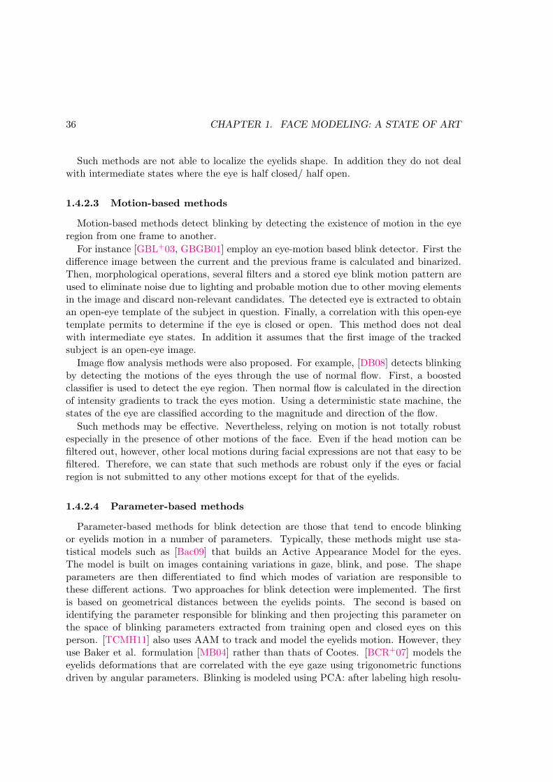
36 CHAPTER 1. FACE MODELING: A STATE OF ART
Such methods are not able to localize the eyelids shape. In addition they do not dealwith intermediate states where the eye is half closed/ half open.
1.4.2.3 Motion-based methods
Motion-based methods detect blinking by detecting the existence of motion in the eyeregion from one frame to another.
For instance [GBL+03, GBGB01] employ an eye-motion based blink detector. First thedifference image between the current and the previous frame is calculated and binarized.Then, morphological operations, several filters and a stored eye blink motion pattern areused to eliminate noise due to lighting and probable motion due to other moving elementsin the image and discard non-relevant candidates. The detected eye is extracted to obtainan open-eye template of the subject in question. Finally, a correlation with this open-eyetemplate permits to determine if the eye is closed or open. This method does not dealwith intermediate eye states. In addition it assumes that the first image of the trackedsubject is an open-eye image.
Image flow analysis methods were also proposed. For example, [DB08] detects blinkingby detecting the motions of the eyes through the use of normal flow. First, a boostedclassifier is used to detect the eye region. Then normal flow is calculated in the directionof intensity gradients to track the eyes motion. Using a deterministic state machine, thestates of the eye are classified according to the magnitude and direction of the flow.
Such methods may be effective. Nevertheless, relying on motion is not totally robustespecially in the presence of other motions of the face. Even if the head motion can befiltered out, however, other local motions during facial expressions are not that easy to befiltered. Therefore, we can state that such methods are robust only if the eyes or facialregion is not submitted to any other motions except for that of the eyelids.
1.4.2.4 Parameter-based methods
Parameter-based methods for blink detection are those that tend to encode blinkingor eyelids motion in a number of parameters. Typically, these methods might use sta-tistical models such as [Bac09] that builds an Active Appearance Model for the eyes.The model is built on images containing variations in gaze, blink, and pose. The shapeparameters are then differentiated to find which modes of variation are responsible tothese different actions. Two approaches for blink detection were implemented. The firstis based on geometrical distances between the eyelids points. The second is based onidentifying the parameter responsible for blinking and then projecting this parameter onthe space of blinking parameters extracted from training open and closed eyes on thisperson. [TCMH11] also uses AAM to track and model the eyelids motion. However, theyuse Baker et al. formulation [MB04] rather than thats of Cootes. [BCR+07] models theeyelids deformations that are correlated with the eye gaze using trigonometric functionsdriven by angular parameters. Blinking is modeled using PCA: after labeling high resolu-

1.5. CONCLUSION 37
tion face examples, PCA is applied and the parameter responsible for blinking is identifiedand used to control the blink motion.
The parameters of statistical-based methods needs identification in order to figureout which one is responsible for the blink motions. In addition, the detection dependson a database containing eyelids variations. [DOG06] employs the parametric Candidemodel [Ryd87] to track the eyelids. The eyelids state is encoded in a parameter responsi-ble for this action beforehand. A threshold on the values of the eyelids parameter permitsto detect the eyes state.
In this thesis, we present a face model that is able to detect blinking by followingthe eyelids motions. The presented blink detection algorithm belongs to the parameter-based category. Compared to some of these methods, the proposed approach does notneed training on subjects performing different eye closures to be able to follow the eyesmotions. It integrates a blinking parameter in the AAM formulation permitting to followthe eyelids of the subject and to give values of the parameter that indicates the degree ofopening of these eyelids.
1.5 Conclusion
In this chapter we have reviewed literature concerning face modeling in both synthesisand analysis domains, in addition to literature concerning gaze and blink detection.
We have seen in the face modeling sections the different face models in both the facesynthesis and analysis domains, together with underlining the advantages and disadvan-tages of one over the other. In an attempt to make benefit of the advantages of more thanone model, some approaches tend to combine two or more different face models.
Among these approaches, [KHH05] apply a combination of different models to find thedifferent features of the face. They use snakes to fit the lips, deformable templates to fitthe eye, k-means clustering combined with snakes to fit the eyebrow. They fit Candidemodel to the face using the extracted control points. This approach does not deal withbig head orientations.
[SUB09] combines 3DMM and AAM to perform robust pose estimation. They buildan appearance model out of a set of 3D laser scans instead of annotated 2D images. Thefitting procedure is exactly as in the classical AAM. [SK07] incorporate active contoursinto the AAM fitting to make it independent of the background of the face image. [SKK07]combines AAM and ASMs. They integrate both models into one objective function wherethe final error to minimize is a combination of the errors of both models. In this way, thetwo models work together to improve the model fitting. [CPP08] proposes the muscle-based anthropometric AAM. Instead of hand-labeling faces in the learning database, theyuse a 3D wireframe mesh. The mesh is placed manually on several faces to build theAAM. They parametrize the facial deformation (expression) based on FACS AUs and themuscle model of Waters [Wat87]. To control person specific characteristics, they employparameters based on anthropometric statistics. They built context-dependent parameters

38 CHAPTER 1. FACE MODELING: A STATE OF ART
called the Expression Action Units (EAU).Combining different models, or applying ideas of one model into another can lead to
better performances. For this reason, we present in this thesis an extension of AAM thatis inspired from some models presented in the above literature survey. We concentrate ourmodel on gaze and blink detection.
In the following chapter, first we detail the formulation of AAM, then we state theirlimitations. The chapter is followed by a proposition of a new model that extends theAAM and makes it more robust to certain limitations by inspiring from ideas of othermodeling techniques reviewed in this chapter.

Chapter 2
Active Appearance Models:Formulation and Limitations
Sommaire
2.1 Active Appearance Model creation . . . . . . . . . . . . . . . . . 40
2.1.1 Shape modeling . . . . . . . . . . . . . . . . . . . . . . . . . . . . 40
2.1.2 Texture modeling . . . . . . . . . . . . . . . . . . . . . . . . . . . 42
2.1.3 Appearance modeling . . . . . . . . . . . . . . . . . . . . . . . . 44
2.2 AAM fitting . . . . . . . . . . . . . . . . . . . . . . . . . . . . . . . 45
2.3 Challenges, Limitations and extensions of AAMs . . . . . . . . 46
2.3.1 Generalization . . . . . . . . . . . . . . . . . . . . . . . . . . . . 47
2.3.1.1 Appearance model extension . . . . . . . . . . . . . . . 48
2.3.1.2 Model adaptation . . . . . . . . . . . . . . . . . . . . . 49
2.3.1.3 Search algorithm extension . . . . . . . . . . . . . . . . 49
2.3.1.4 Hierarchical models . . . . . . . . . . . . . . . . . . . . 50
2.3.2 Non-decoupled parameters . . . . . . . . . . . . . . . . . . . . . . 51
2.3.2.1 Decoupling through factorization . . . . . . . . . . . . 52
2.3.2.2 Decoupling through increasing dimensionality . . . . . 52
2.3.2.3 Decoupling through learning . . . . . . . . . . . . . . . 53
2.4 Conclusion . . . . . . . . . . . . . . . . . . . . . . . . . . . . . . . 54
Active appearance models, originally proposed by [CET98b], are statistical deformablemodels of shape and appearance made starting from several examples. They can be usedto model any object of known morphology. Particularly, they have been widely used formodeling faces.
Generally, AAMs are constituted of two phases (illustrated in figure 2.1), a learningphase (phase of model creation) and a searching phase (phase of model fitting). In thelearning phase, a model is built using the variations between different shapes and texturesof several learning examples. At the end of this phase, each face in the learning database
39

40CHAPTER 2. ACTIVE APPEARANCEMODELS: FORMULATION AND LIMITATIONS
Figure 2.1: Active Appearance Models steps
is described using a set of ”appearance parameters”. These parameters are capable ofregenerating the shape and the texture, and consequently, a near-photorealistic image ofeach of the learning examples.
In the searching phase, a search of the parameters that best describe an unknown facetakes place. For this to occur, a minimization of the difference between the active modeland the real image is done through an optimization algorithm.
In the following, we present the basic formulation of active appearance models. Then,we state its limitations together with the extensions we find the most relevant to our work.We Finally discuss how we inspire from the state-of-art models and the synthesis field tosuggest an extension of Active Appearance Models.
2.1 Active Appearance Model creation
The AAM creation phase is constituted of four major steps. These steps are explainedin the following, and figure 2.2 illustrates them.
2.1.1 Shape modeling
The first step of the model creation phase (also called the learning phase) is the collectionof an adequate learning dataset. The choice of the appropriate learning images plays a

2.1. ACTIVE APPEARANCE MODEL CREATION 41
Figure 2.2: AAM creation–Learning process of Active Appearance models
major role in the quality of the searching results. The more variation the learning databasecontains the more the model will be able to follow the facial variations that might bepresent in the unknown faces to be searched. For example if we want the AAM to be ableto follow a person’s gaze, the learning database should contain people with different gazedirection. The model would then learn these variations and thus will be able to followthem in a new image.
After having chosen the learning database, a second step is the landmark positioning.It is the most cumbersome of the phases of active appearance model building. This stepconstitutes of the placement of definition points on the faces present in the database.These points are put in a way to highlight the borders of the different features of the face(eyes, nose, mouth and chin). One remark is that landmark placement should be donein similar order between the different subjects of the database to ensure correspondencebetween different shapes.
Landmark positioning might be 2D or 3D. In their original form, AAMs are 2-dimensional. However, extensions to AAMs have used 3D landmarks instead [SALGS07b].In this thesis we use the 2.5D AAMs of [SALGS07b], thus 3D landmarks. Examples offace annotations is shown on figure 2.1.
Shape alignment –The set of landmarks of a face constitute its shape. Let Simage be

42CHAPTER 2. ACTIVE APPEARANCEMODELS: FORMULATION AND LIMITATIONS
the shape vector:
Simage = [x1, . . . , xn, y1, . . . , yn, z1, . . . , zn] (2.1)
where n is the number of landmarks.
After the collection of the different shapes, Procrustes analysis [Ros04] is performed inorder to align them. This step aims to filter all the scale, translational and rotationaleffects from the different shapes by aligning them iteratively on their mean. A point topoint correspondence is thus achieved between the different shapes. This alignment resultsin the calculation of the mean shape s and the set of aligned shapes si, where i is theimage number.
Shape variation modeling –To model the shape variation between the aligned shapes,Principle Component Analysis is performed [Jol05, Shl05] on them. Thus, each shape inthe learning base can be described as a linear combination of some modes of variation.
si = s+ φsbs (2.2)
where φs is the matrix of eigenvectors of the covariance matrix of all shapes. bs is thevector of shape parameters. According to the above equation, shape instances can begenerated by modifying shape parameters.
3D pose parameters – Using 3D shapes, 2.5D AAM succeed at synthesizing differenthead poses without the obligation of learning such variation. In other words, there is noneed to learn on people with different poses in order to align faces with different poses. Inthis way, the appearance parameters of AAM do not include information about the headpose of the person. It is only confined with the color and shape of the face in frontal view.The pose vector capable of manipulating the head pose is then:
T = [scalex, scaley, θxy, θyz, θxz, tx, ty]T (2.3)
where scalex and scaley are the horizontal and vertical magnification of the model. θxyis the rotation around the z-axis (head doing circular rotations), θyz is the face rotationaround the x-axis (head shook up and down) and θxz is the rotation around the y-axis(head turned to profile views). tx and ty represent the translation parameters from thesupposed origin.
2.1.2 Texture modeling
Texture alignment – Aligning textures of the learning database means that, for everyimage in the database, to map the pixels under the corresponding shape into one referenceshape. This reference shape is the mean shape calculated from the alignment of the shapesin the previous steps. This operation is called image warping [GM98]. The result is a setof shape free patches, all of the same size. Thus an image texture can be expressed by thefollowing vector:
gimage = [g1, g2, . . . , gm] (2.4)

2.1. ACTIVE APPEARANCE MODEL CREATION 43
where m is the number of pixels in the texture.Texture normalization – This step serves for actualizing illumination effects between
the different textures of the learning database. Many methods were proposed in theliterature to tackle this issue [SKM04]. However, we employ the method used by Cootes.Let gimage be the original texture and gimagenormalized
be the normalized one, then:
gimagenormalized=
gimage − µimage
σimage(2.5)
where σimage =√∑m
i=1 gimage(i)− µimage is the standard deviation of the image andµimage = gimage is the mean of the pixels of the texture.
Figure 2.3: Active Appearance Models Fitting
Texture variation modeling – Modeling the variation of textures is done in a similarway to that of the shapes by applying principle component analysis. Any texture gi canbe represented as a linear combination of some modes of variation.
g = g + φgbg (2.6)
where φg is the matrix of eigenvectors of the covariance matrix of all the textures. bg isthe vector of texture parameters. Synthesis of the different textures can be controlled bythese parameters.

44CHAPTER 2. ACTIVE APPEARANCEMODELS: FORMULATION AND LIMITATIONS
2.1.3 Appearance modeling
Shape and texture models combination – To combine the two models of textureand shape, a third PCA is applied to the concatenation of the texture and shape parame-ters bg and bs. In order to account for the difference between the units of bs and bg wherethe first is in pixel distances and the second is in pixel intensities, a weighting factor Ws
is multiplied to bs.
b =
(
Wsbsbg
)
=
(
WsφTs (s− s)
φTg (g − g)
)
(2.7)
This results in the appearance parameters C capable of manipulating the shape and thetexture simultaneously.
b = φCC (2.8)
Shape and texture can be found using the c-parameters by the following formulas:
s = s+ VsC (2.9)
g = g + VgC (2.10)
where Vs = φsW−1s φC,s, Vg = φgφC,g and φC =
(φC,s
φC,g
)
.
Figure 2.4: AAM training process

2.2. AAM FITTING 45
2.2 AAM fitting
In the searching phase, given a new face image, the aim is to find the pose and ap-pearance parameters that best describe the shape and appearance of the face image inquestion. The model parameters are varied to synthesize new instances of face image. Theproblem is an optimization problem where we opt to find the optimal vector of parametersthat best minimizes the pixel error between the synthesized facial image by the model andthe real one.
∆g = gimage − gmodel(C, T ) (2.11)
E = |∆g| (2.12)
where gimage is the texture vector corresponding to the image, and gmodel is the texturevector synthesized by the model. ∆g is the difference between the two and is called theresidual error. E is the pixel error, defined to be the norm of the residual error. Theoptimization of this error is classically perfomed using simple gradient descent algorithm.
Training – In his original formulation, to solve the optimization problem of the search,Cootes proposed to learn a relationship between the model parameters’ variation and theresidual error between the model and the image. Actually, each face image of the learningdatabase is interpreted using a set of appearance parameters during the learning phase andthus can be synthesized using these parameters. Applying small perturbations to theseparameters and calculating the corresponding residual error permits to learn how to tunethe parameters in the searching phase in a way to drive the model towards the optimum.
∆C = RC∆g (2.13)
∆T = RT∆g (2.14)
where ∆C and ∆T are the perturbations to the model parameters, ∆g is the corre-sponding residual error. RC and RT are the appearance and pose regression matricesrespectively.These are calculated according to the following equation. The mathematicalderivation is found in [CT04].
R =
(
∆g
∆p
T ∆g
∆p
)−1∆g
∆p
T
(2.15)
where p is the parameter in question, it can be either C or T . A glance of the trainingprocess at one iteration is shown in figure 2.4.
AAM search –Having the regression matrices calculated during the training phase,the search is done using these matrices. Figure 2.3 depicts the steps of AAM search. Theseare presented in the following:
– Initialize the model parameters C0 and T0 and set the number of iterationsWhile Number of iterations not reached do
1. Calculate the initial residual error ∆g0

46CHAPTER 2. ACTIVE APPEARANCEMODELS: FORMULATION AND LIMITATIONS
2. Predict displacements in c and t (∆C and ∆T ) according to equations 2.13 and 2.13respectively
3. for k = [1, 0.5, 0.25] called the damping factor
– Predict a new value of C and t: Cki = C0 − ki∆C, Tki = T0 − ki∆T– Generate the model shape smodel and texture gmodel using equations 2.2 and 2.6respectively
– Apply the pose vector on the shape coming from the model to obtain the shapeon image simage
– Map the pixels under simage into the mean shape to form gimage
– Calculate the corresponding residual ∆gki using equation 2.11– Calculate the corresponding error Eki using equation 2.12
4. Update C and T by the one that gives the least error among Cki and Tki
Now that we have detailed the formulation of AAM, we move to specifying the limita-tions in this classical model in the following section.
2.3 Challenges, Limitations and extensions of AAMs
AAMs have proved to be very efficient in modeling faces. However, they still presentseveral drawbacks. To tackle the following presented limitations, researchers have proposedextensions to the AAM initial formulation.
The limitations of AAM concern the initialization of the model, its background, thesearch algorithm, its generalization capabilities which include its robustness to differentfactors (such as illumination variation, occlusions, head pose,. . . ) and finally the fact thatit produces a set of non-decoupled parameters. Concerning initialization and backgroundproblems, the work in this thesis does not deal with these, so we will not review nor discussrelated literature. Moreover, to initialize our model, we use the popular Viola and Jonesface detector [VJ04].
The work in this thesis can be classed in the category of models that deal with gen-eralization and non-decoupled parameters limitations of AAM. For this reason, we placeour literature review in these areas. To increase the generalization capabilities of AAM,some methods tackle the search algorithm. Thus, we additionally review some methodsconcerning this limitation. Figure 2.5 presents the AAM limitations together with thestate-of-art solutions to these.
In the following, we present this review and we position our research with respect tothe state of the art.
For a complete overview of the AAM extensions literature, [GSLT10] is a recent reviewthat studies all of the aspects of these.

2.3. CHALLENGES, LIMITATIONS AND EXTENSIONS OF AAMS 47
����
����������
�������������
��� ������
�������������
��������������
���������
�����������
��������
��������
�����������
��������
������������
�����������
������������������
�������������
������������������
������������������
��������������� �������������������
���������������
�����������������
��������
����������������
Figure 2.5: Limitations of AAM together with some of the methods usually used to solvethese limitations
2.3.1 Generalization
One of the biggest challenges in AAM fitting is to be able to generalize to new examples.This means the ability to give accurate fitting results for faces that are not present in thetraining database. For an AAM to be able to generalize to new faces, the training databaseshould include all the possible variations that might be present in the new image. Thisincludes the variations due to head pose, facial expression, lighting and person-specificcharacteristics such as age, color, and ethnicity, in addition to the presence, or not, offacial hair (beard, buck or hair on the forehead). Even the quality and resolution of thetraining images affects fitting new images.
However, generalizing to new examples is not that easy to reach. In fact, the naivesolution is to include all the possible variations in the database. Unfortunately, thispresents some disadvantages. First, increasing the size of the training database will resultin increasing the number of appearance parameters. This makes the segmentation phaseof AAM more computationally expensive making the models non convenient to a real

48CHAPTER 2. ACTIVE APPEARANCEMODELS: FORMULATION AND LIMITATIONS
time implementation. Second, a learning database containing a many variations can leadto a parameter space containing classes (clusters) corresponding to the different presentvariations. The more the parameter space is clustered, the more gaps will be presentbetween these clusters [SLGBG09]. This makes the convergence of the AAM a moredifficult task.
Methods that try to increase the generalization capabilities of the AAM are many.We will not review all of them, however, we mention those that extend the appearancemodel (section 2.3.1.1), those that adapt the AAM to the person (section 2.3.1.2), thosethat extend the search algorithm (section 2.3.1.3) and finally those that use a hierarchicalrepresentation of the face (section 2.3.1.4).
2.3.1.1 Appearance model extension
The texture in AAM is represented using pixel intensities. This is prone to influenceby appearance variations and thus might affect the fitting results. To improve the gener-alization capabilities of AAM, and thus obtaining better fitting performances on unseenimages, some methods extend the appearance model of AAM. Intensity is replaced byanother representation. For instance, [TAiMZP12] propose the Active Orientation Models(AOMs). In this approach, the authors build the appearance model based on images gra-dient orientation instead of gray-scale image intensities. The authors claim to generalizebetter to unseen faces with respect to the the classical AAM. Figure 2.6 shows a fittingof a face using the AOMs together with the texture representation using the gradientorientation maps. A bunch of approaches use Gabor filters as a representation of the
Figure 2.6: Gradient orientation maps of [TAiMZP12] for appearance representation
image texture [YDJ+13, GSLT09, SGTL08]. Such representation takes into considerationlocal structures of the image [GSLT09]. [GSLT09, SGTL08] directly use the Gabor mag-nitude and phase for the texture representation. The image intensity texture of AAM isconvoluted by Gabor filters. On the other hand, [YDJ+13] propose to use the statisticalcharacteristics of the Gabor magnitude and phase. According to these characteristics,different texture representations are presented and compared. The authors claim that theadvantage of using the statistics of the Gabor filters over directly using the magnitudeand phase as in [GSLT09, SGTL08] is that it is computationally less expensive since theyreduce the dimension of the texture vector of AAM with respect to the formers.

2.3. CHALLENGES, LIMITATIONS AND EXTENSIONS OF AAMS 49
Manipulating the texture representation seems to improve the fitting results of AAM.However, this increases the computation time of AAM since more operations are appliedon the image before collecting the texture information. In this thesis, we do not use suchapproach. We prefer to tackle other sides of the AAM to improve it.
2.3.1.2 Model adaptation
On the other hand, other methods propose to adapt the model to the new face. [SLGBG09]propose the adapted AAM. In this approach, the authors first build a general identityAAM. For an unknown face, the distance between the parameters of this face from thosecorresponding to the faces in the identity database is measured. According to this measure,a model is adapted for this face by building the model on the expressions of the faces thatwere found to be the nearest to the face in question. Although such scheme is efficient,however it still needs the availability of a large database that includes wide variabilities.In addition it might be possible that even with the most adapted model, the results ofsearch wont be accurate. [CK04] adapt the AAM to the identity of the subject. First theyapply an AAM on the neutral face to find the optimal facial features and parameters. A3D face model is then constructed using the aligned face by adapting the resulting textureon a 3D face model. Different views of this model are then used to construct an AAMwhich is adapted to the variability in identity and in pose. This method is dependent ofthe alignment results of the neutral face in addition to the constructed model.
2.3.1.3 Search algorithm extension
One of the reasons of the efficiency of the AAM in terms of speed is its search algorithm.The linear assumption between the texture error and the parameters updates bypassed theneed to deal with a high dimensional non-linear optimization problem, minimizing by thatthe calculation time. Indeed, this whole search scheme including the training phase was oneof the novelties that Cootes had brought to the community. However, it presents certaininconveniences. These come basically from the linear assumption between the textureerror and the parameters updates which was proven to be untrue by [MB04]. When thisassumption fails, convergence of the AAM also fails. This is why many alternatives andextensions were proposed in the literature. We classify these into three classes: Linearregression methods, inverse compositional methods and direct search methods.
Linear regression methods
Due to its efficiency, some methods keep the original optimization scheme but try toimprove different sides of the algorithm. [CT06] and [BH05] update the constant regres-sion matrix in terms of the search image. [DRL+06] replaces the multivariate regressionmethod by Canonical Correlation Analysis (CCA) assuming that it better models the rela-tion between the residual and the parameters update. [CET98a] computes the regressionmatrices based on the shape parameters to reduce the calculation time of the trainingphase and the dimension of the matrices. [SG07] learns the relationship between the

50CHAPTER 2. ACTIVE APPEARANCEMODELS: FORMULATION AND LIMITATIONS
parameter update and the error using non linear boosting.
Inverse compositional methods
Other approaches choose to completely replace the original optimization scheme ofAAM. [MB04, PM08] used the inverse compositional approach. They reformulate the prob-lem as an image alignment problem by relating it to the Lucas-Kanade algorithm [LK81].In this approach the model parameters are updated in function of the residual image, thesteepest descent images, and the Hessian matrix.
Direct optimization methods
Direct optimization methods such as Nedler Mead Simplex algorithm [NM64] andGenetic Algorithm (GA) [Rec71] were also used. These methods are known for theirexploration capabilities (ability to span all the search space of parameters). For in-stance, [SALGS07b] used the simplex to fit the 2.5D AAM. This makes AAMmore efficientin terms of memory consumption and thus more suitable for embedded systems. On theother hand, [SAS08, SMG09] employed the GA in their face alignment search. To decreasethe computation time which is very high, [SAS08] employed a Gaussian mixture clusteringof AAM. [SS10] hybridized simplex and GA to improve the AAM search to obtain evenmore robust and accurate fitting.
Even though such methods take longer time to converge, however their ability to reachoptimal results is bigger than classical linear regression methods. The reason is that the lin-ear regression method updates the parameters according to a non-totally true assumptionof linearity between the model parameters and the texture. Thus, when this assumptionbreaks during the search of AAM, the direct methods will perform better since they do notbase their search on any a priori assumption. Compared to the classical gradient descentalgorithm, the latter exploits the current solution and converges toward the negative ofthe gradient but do not go further. However, these methods expand the search space andexplore every other solutions.
In this work, we use methods from the direct search paradigm to optimize some pa-rameters of our model. We further prove that direct methods work better for us throughseveral experimentations.
2.3.1.4 Hierarchical models
Instead of using one global model to search the face, multiple local models for differentfacial areas (mouth, eyes, nose or upper part and lower part of the face) could be combinedtogether or with the global model to make the search.
[ZC05] proposed the component based AAM. In this approach, iteratively, the sub-models update component points independently then they are united to a global AAM.[Bac09] also uses a similar approach to model the eyes. [RCA03] uses a global modelto apply iteratively-updated soft constraints on a sequence of partially overlapping sub-models. [ZG05] models the face by a two-level hierarchical person-specific model. Thefirst level accounts for the component facial features (mouth and eyes). The second onecombines the facial sub-models to model the final expression using expression variabilities

2.3. CHALLENGES, LIMITATIONS AND EXTENSIONS OF AAMS 51
of sub-components. [PBMD07] proposes the multi-level segmented AAMs. Each segmentencodes a component of the face. A coarse-to-fine fitting strategy which gradually splitsAAM into pre-defined increasing number of segments is used which increases the conver-gence. [XCZL08] proposes the hierarchical-compositional model to model the face. Theface is represented by three layers. The first layer deals with the face as a whole entity.The second one deals with the components constituting the face (eyes, eyebrows, nose andmouth) and refines the alignment of these components using a set of individual templates.The third one deals with the fine details such as wrinkles. They argue that transitionsfrom coarse to final layers leads to structural changes translated by the facial deforma-tions. They deal with these transitions using And-Or graphs. [MCRH06] also employs ahierarchical model of appearance. The major appearance modes of each sub-facial modelencode the major variation for the corresponding area. For example, the highest mode ofvariation in the left-eye model encodes a blink.
Through the use of PCA, AAM supposes a linear relationship between the differentparts of the object in question. This assumption is not always valid. Non-linearitiesof AAM might occur for example in cases of articulated object where some of its partsmove independently. [LPDB05] propose a multi-features method to deal with non linearshape variations of AAM. They use the Minimum Description Length (MDL) to optimallyidentify independent distinct entities of the face called ”cliques”. The MDL automaticallyextracts the cliques from the space of proper values of the learning base of aligned shapes.Each of these entities is then modeled using AAM. Finally, a global AAM is created byregrouping the close cliques two-by-two. Even though this method is efficient for dealingwith the non-linearities of AAM, it is not robust for large head poses.
In this thesis, and due to the efficiency of hierarchical modeling of the face in givingaccurate results for facial features, we use such representation in our modeling. Actually,we use it in two stages of our work. First in our proposed face model described in chapter 3and second in the work presented in chapter 4 which was in the context of a grand challengefor emotion recognition. A detailed description of how this representation was used in ourwork is done in these chapters.
2.3.2 Non-decoupled parameters
One of the problems of standard AAM is that the parameters it gives are not easilydecoupled. Since PCA jointly models all the variations in the database, AAM gives a set ofparameters that are not well-identifiable. Being able to decouple the different parametersinto interpretable ones, or to assign each variation a specific parameter is an importantmatter. Actually, this permits to directly use the information in different contexts ofapplications. In addition, using a non-decoupled model can introduce non-valid spacesand generate non-realistic shape/appearance configurations.
Approaches in the literature try to deal with this issue in different manners. Thesemethods tend to subtract information from the appearance parameters by assigning certainvariabilities of the face (for example, pose, identity or illumination) to a certain number

52CHAPTER 2. ACTIVE APPEARANCEMODELS: FORMULATION AND LIMITATIONS
of parameters other than those in the appearance ones. Thus, the appearance parametersdescribe other variabilities than these entities and the parameters modeling these variationsare optimized in parallel with the appearance parameters. Decoupling can be done usingfactorization, increasing dimensionality or learning.
2.3.2.1 Decoupling through factorization
Some methods tend to factorize the appearance space into several sub-spaces, eachresponsible for a certain variation. Bilinear models were used to decouple variations inpose, identity and expression.
Decoupling pose– [GMDlTM+07] decouples the pose appearance space from the ex-pression/identity space through asymmetric Bilinear AAM (BAAM). Bilinear models aretwo-factor models with the property that their outputs are linear in either factors whenthe other is held constant. They provide rich factor interactions by allowing factors tomodulate each other’s contributions multiplicatively [AD05]. Through this BAAM, dif-ferent poses are possible to be synthesized using a number of parameters that control thepose space.
Decoupling expression – [AD05] also uses bilinear models to separate the expressionand identity factors from the appearance parameters of AAM. The appearance model isbuilt starting from a learning database which is made using a set of neutral and expressivefaces. They compare the performance of asymmetric and symmetric bilinear models forexpression synthesis.
Even though this approach efficiently decouples variations from the appearance pa-rameters of AAM in a way that such variations are independently controllable, howeverthis decoupling is done a posteriori. In other words, such technique does not surpassthe need of a large database containing large variability. In this thesis, we are interestedin subtracting variability from the AAM parameters together with restricting the AAMlearning database. We wish to extrinsically model certain facial deformations. On theother hand, it is not obvious if factorization can be used for decoupling facial actions andnot expressions.
2.3.2.2 Decoupling through increasing dimensionality
In order to decouple the variations in pose from the appearance parameters, somemethods propose to increase the dimensionality of AAMs. This avoids the necessity ofincluding subjects performing head rotations in the learning database and permits toconstruct a sub-space of parameters that controls the variations in pose.
Decoupling pose – [SALGS07b] proposes to combine a 3D shape and a 2D textureto form the 2.5D AAM. The third dimension of the shape corresponds to the depthinformation which is calculated by annotating profile views of the subject’s face. This way,the appearance model is built on frontal-view subjects and pose information is extractedfrom the appearance parameters. [XBMK04] also uses 3D modeling of the shape. The
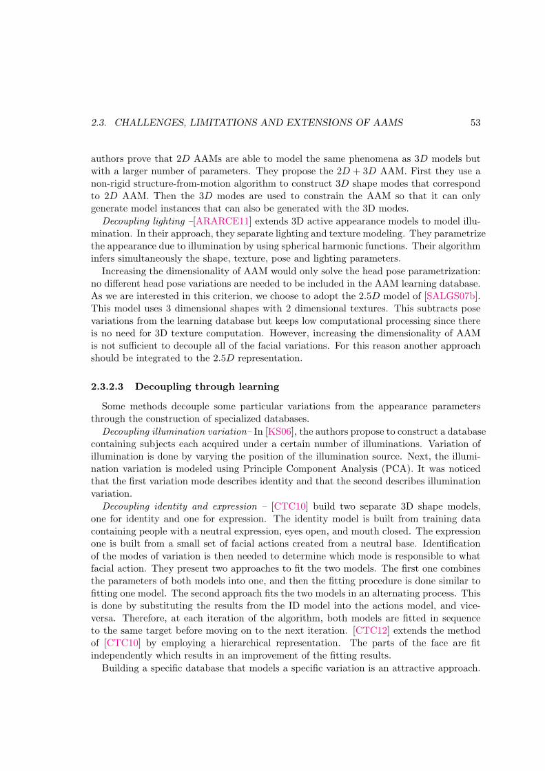
2.3. CHALLENGES, LIMITATIONS AND EXTENSIONS OF AAMS 53
authors prove that 2D AAMs are able to model the same phenomena as 3D models butwith a larger number of parameters. They propose the 2D + 3D AAM. First they use anon-rigid structure-from-motion algorithm to construct 3D shape modes that correspondto 2D AAM. Then the 3D modes are used to constrain the AAM so that it can onlygenerate model instances that can also be generated with the 3D modes.
Decoupling lighting –[ARARCE11] extends 3D active appearance models to model illu-mination. In their approach, they separate lighting and texture modeling. They parametrizethe appearance due to illumination by using spherical harmonic functions. Their algorithminfers simultaneously the shape, texture, pose and lighting parameters.
Increasing the dimensionality of AAM would only solve the head pose parametrization:no different head pose variations are needed to be included in the AAM learning database.As we are interested in this criterion, we choose to adopt the 2.5D model of [SALGS07b].This model uses 3 dimensional shapes with 2 dimensional textures. This subtracts posevariations from the learning database but keeps low computational processing since thereis no need for 3D texture computation. However, increasing the dimensionality of AAMis not sufficient to decouple all of the facial variations. For this reason another approachshould be integrated to the 2.5D representation.
2.3.2.3 Decoupling through learning
Some methods decouple some particular variations from the appearance parametersthrough the construction of specialized databases.
Decoupling illumination variation– In [KS06], the authors propose to construct a databasecontaining subjects each acquired under a certain number of illuminations. Variation ofillumination is done by varying the position of the illumination source. Next, the illumi-nation variation is modeled using Principle Component Analysis (PCA). It was noticedthat the first variation mode describes identity and that the second describes illuminationvariation.
Decoupling identity and expression – [CTC10] build two separate 3D shape models,one for identity and one for expression. The identity model is built from training datacontaining people with a neutral expression, eyes open, and mouth closed. The expressionone is built from a small set of facial actions created from a neutral base. Identificationof the modes of variation is then needed to determine which mode is responsible to whatfacial action. They present two approaches to fit the two models. The first one combinesthe parameters of both models into one, and then the fitting procedure is done similar tofitting one model. The second approach fits the two models in an alternating process. Thisis done by substituting the results from the ID model into the actions model, and vice-versa. Therefore, at each iteration of the algorithm, both models are fitted in sequenceto the same target before moving on to the next iteration. [CTC12] extends the methodof [CTC10] by employing a hierarchical representation. The parts of the face are fitindependently which results in an improvement of the fitting results.
Building a specific database that models a specific variation is an attractive approach.

54CHAPTER 2. ACTIVE APPEARANCEMODELS: FORMULATION AND LIMITATIONS
In the next chapter, we present a face model that uses ideas from this class of methods.The objective of our model is to decouple variations from the appearance parameters ofAAM. To parameterize the motion of the eyeballs for example, we specialize a databasethat models the appearance of the iris. This appearance however has nothing to do withthe eyeball motion and only concerns the color of the iris. Our model thus differs fromthe state of art in this aspect. More details are presented in the dedicated chapter (cf.chapter 3).
2.4 Conclusion
We have presented, in the above, the formulation of Active Appearance Models. Wehave also underlined the limitations and challenges of the standard AAMs. We havefocused on two limitations: the generalization capabilities of AAM and the fact that theparameters produced by AAM are non-decoupled and well-defined.
In order for an AAM to be able to generalize to new faces and to produce accuratefitting results, a large database containing wide variations should be constructed. Thisincreases the number of appearance parameters making the AAM non-suitable for realtime applications. Generalization capabilities of AAM have been tackled in the literatureusing: Appearance model extension, Model adaptation, Search algorithm extension andHierarchical models. Among these, the hierarchical modeling of the face leads to moreaccurate results in specialized regions such as the eyes and mouth. We thus present amodel that uses such representation.
On the other hand, compared to the models existing in the literature (reviewed in thepast chapters) such as Candide model and parameter-based models used in the synthesisdomain, AAM does not produce identifiable parameters. Nevertheless, AAM is based onreal data.
Our idea in this thesis is to propose a face model that decouples some facial actions fromthe appearance parameters of AAM. The model deals with the different parts of the faceas different objects which can be related to hierarchical models where each region of theface is assigned a separate model. A set of parameters are added to the AAM formulation.These are responsible for some eye action such as the gaze and the blink. This modelrestricts the learning database of AAM to little variations concerning identity for examplemaking the model more suited from real-time applications. The proposed model is able togeneralize better to new faces with respect to the classical AAM. The ultimate goal is amodel made starting from a training database that contains expressionless subjects but isable to track people with different expressions and head pose. Details on our propositionare presented in the next chapter.

Chapter 3
A multi-object facial actions AAM
Sommaire
3.1 Introduction of the proposed model . . . . . . . . . . . . . . . . 56
3.1.1 Facial Action AAM . . . . . . . . . . . . . . . . . . . . . . . . . 59
3.1.2 Multi-Object AAM . . . . . . . . . . . . . . . . . . . . . . . . . . 63
3.1.2.1 Modeling . . . . . . . . . . . . . . . . . . . . . . . . . . 63
3.1.2.2 Searching: fusion of the eye skin and iris models . . . . 66
3.1.3 Multi-Objective modeling: general idea . . . . . . . . . . . . . . 71
3.1.3.1 Integration in the gaze detection system . . . . . . . . . 72
3.1.3.2 Multi-objective optimization . . . . . . . . . . . . . . . 72
3.2 Tests and Results . . . . . . . . . . . . . . . . . . . . . . . . . . . 75
3.2.1 Blink detection . . . . . . . . . . . . . . . . . . . . . . . . . . . . 76
3.2.1.1 Comparison between different one eye models . . . . . . 77
3.2.1.2 Integrating blink parameter into the whole face . . . . . 80
3.2.1.3 Test in generalization . . . . . . . . . . . . . . . . . . . 80
3.2.2 Gaze detection . . . . . . . . . . . . . . . . . . . . . . . . . . . . 83
3.2.2.1 Accuracy of the eye skin model . . . . . . . . . . . . . . 85
3.2.2.2 Comparison between different optimizations . . . . . . 90
3.2.2.3 Multi-Objective AAM vs. Single-Objective AAM . . . . 91
3.2.2.4 3D MT-AAM vs. 2D MT-AAM vs. classical AAM . . . 93
3.2.2.5 Comparison with a state-of-the-art method . . . . . . . 98
3.3 Conclusion . . . . . . . . . . . . . . . . . . . . . . . . . . . . . . . 99
When a person sees another person, he directly recognizes his different facial features.He can automatically identify their shapes and easily interpret any movement of these.The human mind is used to such identification and interpretation. The objective of a facemodel is to automatize the identification and the interpretation of facial features and theirmotion. The more the face model is capable of this interpretation, the more efficient it isto be integrated in real world automatic scenarios.
55

56 CHAPTER 3. A MULTI-OBJECT FACIAL ACTIONS AAM
The goal of this chapter is to introduce a new model of the face. Inspiring from ideascoming from the synthesis domain (see state-of-art methods concerning this domain inchapter 1, section 1.2), we propose the multi-object facial actions AAM optimized usinga framework of a multi-objective optimization.
The eyes, being the window to the brain and soul, play an important role in under-standing human intentions and emotions. Eye movements in particular are primary cuesof non-verbal communication. Through our eyes’ gazing and blinking, we can communi-cate messages to people around us. Through these motions we equally interact, act andreact. A face model that is capable of accurately interpreting these motions is an impor-tant requirement for automatic face analysis. Accordingly, we orient our face model forthe purpose of gaze and blink detection.
The organization of this chapter is as follows. First, we describe the global idea ofour proposed model in section 3.1. In sections 3.1.1, 3.1.2 and 3.1.3, we permeate in thedetails concerning the proposed model. Section 3.2 presents different results concerningthe application of the model to the problematics of gaze and blink detection. Finally, insection 3.3 we conclude the chapter.
3.1 Introduction of the proposed model
One of the major disadvantages of statistical Active Appearance Models is the necessityof a big training database that includes all the possible variations in facial expressionsand motions so that the model would be able to robustly align the face and accuratelyfind its features. In this thesis, we aim at producing the variations due to certain facialactions without the necessity of including subjects performing these actions in the learningdatabase of AAM. In this way, we subtract from the appearance parameters of AAM thevariations corresponding to certain motions of the face. Just like the head pose is modeledseparately from the appearance parameters in the 2.5D AAM such that there is no needto include faces with different head poses in the learning database in order to find the headpose of a new face image, we want to reach an AAM where facial motions are modeledseparately.
We thus propose to extend the pose parameters of AAM. We present a new face modelthat combines the advantages of the statistical AAM and the interpretable parameters ofmodels such as Candide. This model parametrizes some facial actions which are simple tobe parametrized such as the eyebrows, the eyelids and the eyeballs motion, but keeps theAAM statistical learning for more complicated parts of the face such as the mouth or theeyes shape. Figure 3.1 illustrates the idea of the model. It shows the deformable AAMwith the different facial actions on it. Section 3.1.1 details this proposition.
In our proposition, the face is represented as an aggregation of different objects. Eachobject is related to a specific texture. An object can be any facial feature or a combinationof facial features. For example it can be the mouth, the left eye, the right one, botheyes or the whole face. The choice of the division of the face into the specific objects

3.1. INTRODUCTION OF THE PROPOSED MODEL 57
Figure 3.1: Facial actions representation of the face
������
������
Object Object
������
Object
Figure 3.2: Multi-Object representation of the face
depends on the problem in question. Moreover, inspiring from the synthesis domain, oneparticularity of our model is that we consider that the eyeballs are separate entities from

58 CHAPTER 3. A MULTI-OBJECT FACIAL ACTIONS AAM
the face. Figure 3.2 illustrates this representation of the face and section 3.1.2 details it.Separating facial objects contributes in decreasing the size of the database of AAM sincethe object can be tuned separately. This evades including cases where mutual variations indifferent features should be included. For example, for a global face to be able to analyzecases where a subject opens his mouth and moves his eyebrows in different positions,the database should contain the combination of the mouth movement and these differenteyebrow movements.
As we want to analyze the face in different poses, the information from different objectsdoes not have the same quality. For instance, the left eye can not be analyzed with thesame quality as the right one in some cases if the face has a big orientation. Thus, wepropose a multi-objective optimization for the proposed model. This optimization takesinto account the head pose to favor one or more objects over the others in specific cases.This is detailed in section 3.1.3.
The proposed model includes the following parameters:
AAMFacialactions Object(i) appearance parametersHead pose parametersgaze parametersEyelids parametersEyebrows parameters
where Object(i) ∈ {Lefteye,Righteye,Mouth,Globalface}.
We orient our model principally towards gaze detection. The motivation behind this isattributed to the importance of such analysis for HCI. As a matter of fact, gaze detectionenters in wide various applications starting from entertainment interactive applications(virtual reality or video games ([IJSM09])), video conferencing ([Ver99]), aiding disabledpeople (eye typing or eyes for moving cursors ([VdKS11])) to applications anticipating hu-man behavior understanding through eyes. On the other hand, extracting eye informationis not an easy task. This can be summarized by the following:
– The eye changes its states with every blink and with every iris motion;– It can be occluded by different factors such as eyeglasses and hair;– It has a small texture with respect to that of the skin surface;– It is influenced by the variability in the light conditions and in iris location, color andscale.
To tackle these difficulties, we show how our proposed model applied to the gaze detectionproblematic increases the robustness of gaze detection with respect to classical AAMs (cf.section 3.2).
In the following sections, we detail our proposed model. Section 3.1.1 presents theFacial-Actions AAM. It concerns parameterizing facial motions that are coupled with theskin such as the eyebrows and eyelids motions. Section 3.1.2 presents the Multi-Object

3.1. INTRODUCTION OF THE PROPOSED MODEL 59
AAM. It concerns dealing with the face as several objects. Section 3.1.3 presents themulti-objective optimization framework used in our work.
3.1.1 Facial Action AAM
Figure 3.3: Identification of the principle axes of the displacement of the facial landmarksof one subject. These landmarks are traced while the subject blinks his eyes, lowers hiseyebrows, frowns and says A/I/O phonemes.
As we have previously said, we are interested in an Active Appearance Model thatis capable of generating valid movements of the different parts of the face without thenecessity of including such variations in the database. To parameterize the motions ofthe eyebrows and eyelids, we study the variations of specific local points of the face.In this approach, we have inspired from the method employed by [SBS10] for modelingfacial dynamic transitions during an expression for the purpose of facial animation. Theauthors were interested in observing short term dynamics controlling the transition fromone expression to another. So they have collected a 2D database of varied dynamicemotional facial expressions performed by an actor and tracked the movement of a set ofmarkers over time.
Hence, we have took a similar path to analyze the movements of eyelids, eyebrows andthe mouth. We have asked 10 subjects to perform a number of specific actions with theireyelids, eyebrows and mouths. These actions are constituted of: 2 consecutive blinks,eyebrows up and down, frown, and the pronunciation of three letters to simulate threemouth movements (”A” to simulate open mouth, ”O” to simulate round-shape mouthand ”E” to simulate a smile). The videos were then annotated and global head motionwas filtered using Procrustes Analysis. Next, the trajectories of each of the landmarksduring the before-mentioned facial actions were observed. Figure 3.3 shows the landmarks
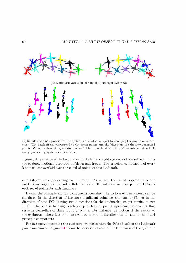
60 CHAPTER 3. A MULTI-OBJECT FACIAL ACTIONS AAM
(a) Landmark variations for the left and right eyebrows
(b) Simulating a new position of the eyebrows of another subject by changing the eyebrows param-eters. The black circles correspond to the mean points and the blue stars are the new generatedpoints. We notice how the generated points fall into the cloud of points of the subject when he isreally performing eyebrows movements.
Figure 3.4: Variation of the landmarks for the left and right eyebrows of one subject duringthe eyebrow motions: eyebrows up/down and frown. The principle components of everylandmark are overlaid over the cloud of points of this landmark.
of a subject while performing facial motion. As we see, the visual trajectories of themarkers are organized around well-defined axes. To find these axes we perform PCA oneach set of points for each landmark.
Having the principle motion components identified, the motion of a new point can besimulated in the direction of the most significant principle component (PC) or in thedirection of both PCs (having two dimensions for the landmarks, we get maximum twoPCs). The idea is to assign each group of feature points significant parameters thatserve as controllers of these group of points. For instance the motion of the eyelids orthe eyebrows. These feature points will be moved in the direction of each of the foundprinciple components.
For instance, concerning the eyebrows, we notice that the PCs of each of the landmarkpoints are similar. Figure 3.4 shows the variation of each of the landmarks of the eyebrows

3.1. INTRODUCTION OF THE PROPOSED MODEL 61
for one subject while performing the eyebrows movements. It is clear from the figurethe resemblance of the PCs of these landmarks. In other words, we can notice thatall the landmarks of the eyebrows move in similar directions when performing up/downmovements or frowning. For this reason, we approximate the PCs of each of the landmarksof the eyebrows by those of one landmark. These PCs identify two parameters responsiblefor the eyebrows motions. The first parameter is responsible for the up/down action andthe other parameter is responsible for the frown action. Let TEBL and TEBR be the actionvector containing the parameters responsible for the left and right eyebrows movementsrespectively. The eyebrows parameters become:
TEBLφL = [TLhorT
Lver]φL (3.1)
TEBRφR = [TRhorT
Rver]φR (3.2)
where φL and φR contain the eigenvectors of the covariance matrix of the specific land-marks we chose of the left and right eyebrows respectively.
Concerning the eyelids motion. Two actions are possible: winking and blinking. How-ever, blinking is more frequent. As a starter and to stay simple, we assign only oneparameter for both eyes, thus winking is not possible using our model.
Figure 3.5: Variation of the landmarks for the left and right eyes of one subject duringblinking. The principle components of every landmark are overlaid over the cloud of pointsof each of these landmarks. The red stars represent the mean of each of the landmarks.
The landmark motion analysis of figure 3.5 shows that during blinking, both the upperand lower eyelids move in addition to the corner points. However the motions of the lowerand the corner points can be considered negligible with respect to the upper ones. Inaddition, [TCMH11] proved in their experiments that the lower eyelids motion has noeffect on the results of animating characters. For this reason, we assume that during blink-ing, only the upper eyelids move in our model. Let TBlink be the parameter responsiblefor the blinking motion. Figure 3.5 also shows that the principle directions of the upperlandmarks are vertical. Thus, it is sufficient to add the blinking parameter to the uppereyelid points in the vertical direction.

62 CHAPTER 3. A MULTI-OBJECT FACIAL ACTIONS AAM
Integrating the blinking parameter in the AAM considers only the searching phase.Actually, the goal is to restrict the learning base of AAM so that it would be able todetect different eye states without the necessity of including this variation in the learningdatabase. Thus, training is done on a set of open-eyed images. The pose and appearanceparameters are trained normally using regression matrices. Then a blinking parameter istuned during the searching phase of AAM. This blinking parameter is normalized between0 and 1. The 0 value corresponds to an open eye whereas the 1 value corresponds to aclosed eye. Values between 0 and 1 correspond to intermediate eyelid closures.
Since the search space of the blink parameter is considerably small, exhaustive searchseems convenient. Exhaustive search, also called brute-force search consists of checkingthe set of all possible solutions of the search space. At each iteration of the AAM search,we tune the blinking parameter between 0 and 1 with increments of 0.1. We calculate thecorresponding fitness and we choose the set of C, T and Tblink parameters that give theminimum fitness to pass to the next iteration. The AAM search becomes the following.
– Initialize model parameters C0 and T0
– Set the number of iterationsWhile Number of iterations not reached do
– Calculate the initial residual error δg0– Predict displacements in C and T (δC and δT ) according to equations 2.13 and 2.13respectively
– for k = [1, 0.5, 0.25] called the damping factor– Predict a new value of C and T : Cki = C0 − kδC, Tki = T0 − kδT– for Tblink ∈ [0, 0.1, 0.2, . . . , 1]
– Generate the model shape smodel and texture gmodel using equations 2.2 and 2.6respectively
– Apply the pose vector on the shape coming from the model to obtain the shapeon image simage
– Apply T imageblink on the resulting simage where
T imageblink = Tmodel
blink × scaleimagetomodel (3.3)
Tmodelblink = Tblink ×MeanEyeHeightmodel (3.4)
scaleimagetomodel =InterOcularDistanceInImage
InterOcularDistanceInModel(3.5)
Tmodelblink is the value of the blink parameter in the model space. It is approxi-
mated to be a fraction of the eye height of the mean shape: MeanEyeheightmodel.T imageblink being the value of the blink parameter in the image space, scaleimagetomodel

3.1. INTRODUCTION OF THE PROPOSED MODEL 63
being the scale that maps a point in the image plane into the model plane. TheInterOcularDistanceInImage is calculated using the distance between the re-ality points corresponding to the eyes and the InterOcularDistanceInModel iscalculated by calculating the distance between the mean of the eyes points of themean shape.
– Map the pixels under simage into the mean shape to form gimage
– Calculate the corresponding residual δgki using equation 2.11– Calculate the corresponding error Eki using equation 2.12
– Update C, T , and TBlink by the one that gives the least error among Cki and Tki
In the following, we detail how we parameterize the actions of the eyeballs.
3.1.2 Multi-Object AAM
Continuing to generate movements of facial components without the necessity of in-cluding such movements in the learning base of AAM, we move to parameterizing gaze.In this section we show how we construct the AAM containing a gaze parameter at thelevel of one eye. This requires the fusion of 2 AAM, one for the iris texture and one forthe surrounding skin (where a hole is put inside the eye). The following further detailsthis approach.
3.1.2.1 Modeling
Most computer graphics methods model the eyeballs as separate objects from the facialskin (cf. figure 3.6). In these methods, the eyeball is located behind a 3D mesh thatrepresents the facial skin and that has openings between the eyelids. In the facial analysisframework, particularly in the analysis-by-synthesis approaches, the eyeball is not modeledas a rotating 3D sphere located behind the skin surface. Instead, the visible region of theeyeball is a part of a continuous face mesh.
We inspire from the computer graphics community to parametrize the motions of theeyeballs to propose a multi-object representation: The basic idea of this representation isthat the interior of the eye is considered as a separate object from that of the face whichis another object. These two objects deform separately and are assigned each its ownset of parameters. By permitting the eye object to slide under the skin surface object,we succeed at synthesizing any gaze direction and consequently at parameterizing the irismotion (cf. figure 3.7). An object in our case is either the eye skin or the iris texture. Wethus choose to name our approach the Multi-Texture AAM.
To accomplish the decorrelation of the eye skin from the iris, the facial skin objectshould be modeled separately from the iris texture. Thus, we put holes inside the eyesin the place of the iris-sclera part. This permits to subtract the variability that the irisundergoes (scale, color and position) from the appearance parameters of the eye AAM.
Formally, equations (2.9) and (2.10) become

64 CHAPTER 3. A MULTI-OBJECT FACIAL ACTIONS AAM
Figure 3.6: Illustration of modeling the eyeball as a sphere in computer graphics
sface =
(
sskinsiris
)
=
(
sskinsiris
)
+
(
V skins Cskin
V iriss ciris
)
(3.6)
gface =
(
gskingiris
)
=
(
gskingiris
)
+
(
V sking Cskin
V irisg ciris
)
(3.7)
where Ciris only encodes variations corresponding to the iris’s appearance and shape.It has nothing to do with its scale and movements.
3.1.2.1.1 Local eye skin AAM
This model is built using 22 landmarks that describe the whole eye area, including theeyebrows and the texture surrounding the eye. Figure 3.11(a) is an illustration of the meantexture of the eye skin model showing the hole inside the right eye with the annotationsto obtain this model.

3.1. INTRODUCTION OF THE PROPOSED MODEL 65
Figure 3.7: Multi-texture idea illustration. Moving the iris texture behind the eye skinsurface creates different gaze directions.
3.1.2.1.2 Iris AAM
In order to build this AAM, we need an iris-sclera texture that is capable of slidingunder the eye skin. We construct our iris training database starting from the iris imagesof [CCD00] and [DMTP04]. We reprocess these images to obtain the iris part. We thenmerge it with a white texture. We make the sclera texture by cropping a small area fromthe sclera in the original iris images and resizing it (cf. figure 3.8). Cropping from the sclerapresent in each image to reproduce the white texture results in different textures whichare not totally white. This permits to learn different white information in the trainingphase of the iris AAM, thus making the model capable of coping with the variation of thesclera color from one person to another. The original iris images are of high resolutionand they present unnecessary details in the iris texture. We resize these images and applya circular averaging low pass filter to decrease the amount of information in the iris area.
For training these iris images we use a model of 13 landmarks of which 8 describe theshape of the iris in frontal view and 1 describes the approximative position of its center;to learn the white texture around the iris, 4 additional landmarks forming a rectangularshape around the iris are placed. Figure 3.11(b) is an illustration of the mean texture ofthe iris model with the corresponding annotations. These iris images are used in a 3Drepresentation of the eyeball.

66 CHAPTER 3. A MULTI-OBJECT FACIAL ACTIONS AAM
Figure 3.8: An example of a training iris image before and after processing (remark thatthe original image is of a very high resolution)
As we see from figure 3.7, when the iris texture slides to the extreme left or the extremeright using simple translation in 2D, the appearance of the eye becomes unrealistic. Inreality, the iris is a part of a spherical eyeball. As the eyeball rotates to extreme positions,the iris’s appearance becomes elliptical rather than circular. Thus, modeling the iris in 2Dis not sufficiently realistic and may cause problems in detection. This is why, we proposeto model the iris as a part of a 3D eyeball (cf. figure 3.12).
Modeling the interior of the eye as a sphere and rotating it under the skin surface, anygaze direction can be synthesized. Consequently, the iris motion is parameterized andrealistically modeled.
T iris =[
Sirisθhorθver]
(3.8)
where Siris is the scale of the iris, θhor is the horizontal rotation of the eyeball and θveris its vertical rotation.
3.1.2.2 Searching: fusion of the eye skin and iris models
Fusion of the eye skin model and the iris one is done in the searching phase. First wefind the optimal parameters for the eye skin (using the eye skin model) in a prior step. Wethen use the found parameters to reconstruct the image describing the eye skin. The irismodel rotates under it with the pose vector T iris describing the iris position with respectto eye.
To merge the eye skin object and iris models, we simply replace the hole in the skinmodel (figure 3.11(a)) with the pixels of the iris model (figure 3.11(b)). After replacement,a problem of discontinuity between the two models arises (cf. figure 3.9). As we see, the

3.1. INTRODUCTION OF THE PROPOSED MODEL 67
resulting eye model seems unrealistic, especially at the borders of the eye skin model. Inorder to resolve this, we apply a circular averaging low pass filter of radius R = 2 on theskin and white parts while preserving the iris:
Figure 3.9: Discontinuity between the eye skin object and the iris object when mergingthem
h (x, y) =
{
0 if√
(x2 + y2) > R1
πr2if√
(x2 + y2) ≤ R
It smooths the discontinuity between the eyelid and the iris, and also reproduces theshadow effect of the eyelid on the iris. We remark that the filter is not applied on the irissince it is essential to preserve a good image quality of the iris in order to guarantee thelocalization. This is done using the mask shown in figure 3.11(d). The filter is applied onall the pixels of the white area of the mask. We remark that some pixels of the perimeterof the iris are non-intentionally affected by the application of the filter using the mask (cf.figure 3.10). This is because the landmarks of the iris are not abundant (8 landmarks).Thus, it causes the inclusion of some pixels of the perimeter of the iris in the region ofapplication of the mask. However, this does not affect the detection since it only concernsfew pixels. This results in the final model describing the eye region (figure 3.11(e)).
The following sums up the whole eye AAM fitting process using the 3D representation.Algorithm
Steps for fitting the 3D MT-AAM for one eye:

68 CHAPTER 3. A MULTI-OBJECT FACIAL ACTIONS AAM
Figure 3.10: Iris border pixels affected by the application of the filter
1. Localize the eye using the eye skin model.2. From the webcam image, extract the texture of the eye (gi) (figure 3.11(f)).3. Using the optimal parameters found by the eye skin model, synthesize the eye skin
(geyem ) (figure 3.11(a)).4. Until the stop condition (number of iterations reached) do:
(a) Create the model texture of the iris (girism ) based on the pose and the appearanceparameters of the iris model (figure 3.11(b)).
i. Project the 2D shape of the iris on the sphere (figure 3.12(i))
ii. Rotate the iris and the sphere in 3D (figure 3.12(ii))
iii. Project the 3D iris on 2D (figure 3.12(ii))
iv. Map the iris texture on the rotated shape (cf. figure 3.11(b))
(b) Merge the two textures geyem and girism to obtain the texture gm (figure 3.11(c)).
(c) Apply a selected low pass filter to get the final eye region model gm (fig-ure 3.11(e))
(d) Evaluate the error E: E = gi−gm in the interior of the eye region (figures 3.11(g)and 3.11(h))
(e) Tune the pose and appearance of the iris model.

3.1. INTRODUCTION OF THE PROPOSED MODEL 69
Figure 3.11: Error Calculation at one iteration. At each iteration, the eye skin model ismerged with the iris one to obtain the final eye model which is compared to the real eyeto get the error

70 CHAPTER 3. A MULTI-OBJECT FACIAL ACTIONS AAM
Figure 3.12: Illustration of modeling the iris as a part of a sphere. See how the irisappearance becomes elliptical in appearance for extreme gaze directions
Note that the evaluation of the error is computed in the interior of the eyes and notover the whole eye region. This is because the eyes skin texture is the optimal one, so itis unnecessary to include the skin texture in the error calculation. It will only add noiseto the latter.
Eyeball diameter – The average diameter of the iris in the human eye is around 12mmand the average eyeball diameter is around 26mm. Thus, we fix the ratio between the irisdiameter and that of the eyeball to 0.45. We calculate the iris diameter from the meanshape of the iris model and deduce the eyeball’s diameter using the fixed ratio.
��
�� ��
ααααββββ
γγγγ
ααααββββ
γγγγ
���
���
���
Figure 3.13: Barycentric coordinates
Back projection of iris shape When the optimal iris shape is found in the modelframe, it should be back-projected to the real image. Actually the optimization of theiris parameter takes place in the model frame where the eye texture is warped from theweb-cam image frame to the mean model of the eye. The iris position is then optimized

3.1. INTRODUCTION OF THE PROPOSED MODEL 71
with respect to the midpoint of the mean eye shape. In order to retrieve the iris position inthe original image using the iris parameters found in the model frame, we use barycentriccoordinates. This is the same approach used in warping from one image to another. LetSmodeliris be the optimal iris shape found in the model frame and Simage
iris the iris shape inthe real image. To find this latter:
– Perform Delaunay triangulation on the Smodeleye
– For every point smodeli ∈ Smodel
iris
– Determine the triangle that smodeli belongs to among the triangles of the Delaunay
triangulation:– Transform the coordinates of smodel
i (x, y) into barycentric coordinates of eachof the triangles of the Delaunay triangulation. Let αt, βt, γt be the barycentriccoordinates of smodel
i w.r.t each triangle having vertices ri of cartesian coordinates(xi, yi), i ∈ 1 . . . 3, then smodel
i belongs to triangle t if 0 < αt, βt, γt < 1.
– Find the position in the original image: simageiris = αtr
′
1+βtr′
2+ γtr′
3 where r′i are
the vertices of the triangle t′ that simageiris belongs to and that corresponds to t
3.1.3 Multi-Objective modeling: general idea
We have seen in the previous section how dealing with the eyeball as a different objectfrom that of the eye skin permits the coding of gaze in a separate vector of parametersthan those of the AAM appearance parameters. In this section, we show another aspect ofmulti-object modeling. This aspect concerns partitioning the facial skin itself to differentobjects and linking these in a multi-objective optimization framework.
As a matter of fact, one of the challenges of AAMs is to be able to deal with changesof appearance that the face would be submitted to. These appearance changes might bedue to occlusions such as head pose. As the face is changing its pose, some features of theface might be partially or totally occluded.
A multi-object representation of the face helps promoting one or several objects overthe others in the presence of head pose. This works as follows: the face is partitioned intoseveral objects, and each object has its own residual error. According to certain factors(such as occlusion of a feature of the face), one or several features are favored over theothers.
If E1, E2, ...Ei are the residual errors of each ”object”. Optimizing these errors leads toa multiobjective optimization. Each error is assigned a weight and the resulting errors areadded to form one final error. The weights serve at favoring one object over the others.In this way, occluded parts of the face can be penalized less and thus they contribute lessto the final error.
Efinal = α1E1 + α2E2 + . . . αiEi (3.9)

72 CHAPTER 3. A MULTI-OBJECT FACIAL ACTIONS AAM
where i is the number of defined objects of the face. αi is the weight assigned to eachobject.The number of different objects and the weights can be defined depending on thenature of the application and its requirements. We will show in section 3.1.3.1 how wedefine these in the context of a gaze detection application.
We note that this approach can be related to hierarchical models (cf. section 2.3.1.4)where each region of the face is assigned a separate model. However, non of these methodsrelate the different regions to each other through a multiobjective optimization.
3.1.3.1 Integration in the gaze detection system
Let us consider that a subject is in front of the screen where a webcam is installed(first block of figure 3.14). Depending on the face orientation, the left and right eyes areunevenly represented in the webcam image. In other words, the face orientation in thiscase causes partial or complete occlusion of one eye with respect to the other. As we areconcentrating on gaze, then there is no need to integrate the lower part of the face in themodel. Thus, we partition the upper region of the face into two: the left eye region andthe right eye region. The gaze is analyzed using a multi-objective optimization with localmodels containing gaze parameter for each eye (one Multi-Texture AAM (MT-AAM) foreach eye): The contribution of each eye to the final gaze direction is weighted dependingon the detected face orientation.
Figure 3.14 depicts the steps of our global system. We distinguish between three mainzones depending on head orientation.
(A) The subject could have a head pose such that both of his eyes appear clearly on thescreen;
(B) The subject shows a large head rotation to the left such that the right eye appearsthe most in the camera;
(C) The subject shows a big head pose to the right such that the left eye appears more;
The algorithm works as follows: The first step is the detection of the head pose forwhich a 2.5D global AAM model ([SALGS07a]) is applied. If the head pose correspondsto the Zone A, then both eyes will be integrated in the detection of the gaze using aweighting function. If it is in the Zone B, an MT-AAM will be applied only on the righteye. If it is in the Zone C, then MT-AAM will be applied only on the left one.
3.1.3.2 Multi-objective optimization
Since normally the two eyes have highly correlated appearance and motion, we useonly one pose vector and one appearance vector to describe the pose and appearance ofboth irises. Technically, it should be sufficient to analyze the iris of one eye to obtain itsposition and appearance in both eyes. Yet, the information from both eyes can lead toa more robust system especially when the person commits large head movements around

3.1. INTRODUCTION OF THE PROPOSED MODEL 73
Figure 3.14: Global system overview; Zone A means that the face rotation is sufficientlysmall such that both eyes appear in the camera. Zones B and C signify that the right orthe left eye appear more in the camera respectively
the vertical axis where one of the eyes can be partially or completely occluded. This issolved by the multi-objective AAM framework presented in section 3.1.3.
The idea is that we deal with the eyes as if they were two separate images acquired atthe same time: MT-AAM (see section 3.1.2) is applied simultaneously on both eyes and ateach iteration, and the resulting errors are summed while multiplying each by a weightingfactor that is a function of the head pose.
In this system, a single iris model is merged simultaneously with the left and the right

74 CHAPTER 3. A MULTI-OBJECT FACIAL ACTIONS AAM
eye skin models. Then the resulting models are overlaid on both the right and the lefteyes from the camera to get the left and right errors. These are weighted according to thehead orientation and summed to get one global error. This error becomes:
E = αEleft + βEright (3.10)
where Eleft and Eright are the errors corresponding to the left and right eyes respectively.α and β are the weighting factors. They are functions of the head rotation around the z-axis (Ryaw), evaluated just after the face detection, and they both follow a double logisticlaw:
α(Ryaw) =
0.5 if −d ≤ Ryaw ≤ d0 if −90◦ < Ryaw ≤ −22◦
1 if 22◦ ≤ Ryaw < 90◦
0.5(1 + l(1− exp−(Ryaw−ld)2
σ2 )) else
β(Ryaw) = 1− α (3.11)
where l = sign(Ryaw), σ is the steepness factor and d is the band such that the twofunctions α and β are equal to 0.5. d is chosen to be 7◦ such that for this value we considerthat the orientation of the head is negligible and that both eyes contribute equally. A headrotation of 22◦ is considered to be big enough to make one of the eyes appear more thanthe other in the image, and thus, this eye is exclusively taken into consideration in thedetection of the iris. σ is found empirically. In this way, the face orientation is taken into
−20 −10 0 10 200
0.2
0.4
0.6
0.8
1
Ryaw
Pen
aliz
atio
n fa
ctor
αβ
Figure 3.15: Double logistic function, d = 7. Ryaw is in degrees.
account by the relevant information from both eyes.

3.2. TESTS AND RESULTS 75
To minimize the error in equation (3.1.3.2), we have tried several optimizations: Gra-dient Descent (GD), Simplex, and Genetic Algorithm (GA). After comparison of these(cf. sectionsec:optimizationcomp), we have chosen the genetic algorithm to optimize theproposed gaze pose vector.
Genetic Algorithm (GA) [Rec71] is a population-based iterative search heuristicthat aims at finding the set of parameters that optimizes a certain cost function. It isinspired from the process of natural evolution. A set of candidate solutions evolves towardsa better set until arriving at the best one.
The iris pose and appearance form the genes of the GA. They are combined into asame vector to form a chromosome (cf. figure 3.16).The group of chromosomes form apopulation. At each iteration, a population of solutions is formed. Their correspondingfitness is computed. According to the latter, some of these chromosomes are set to be theparents of the population of the next iteration.
� �
1irisC iris
nC1irisT 2
irisT 3irisT
Figure 3.16: A chromosome of the genetic algorithm; The parameters inside are those ofthe iris appearance and pose
Briefly, the options of the GA that we found to be the best suited to the optimizationof the iris parameters are the following:
Initialization: The initial population is generated randomly between the upper and thelower limits of the parameters with a uniform distribution. This allows to span all thesearch space.
Selection: This is the act of choosing the parents for the production of the new gen-eration. We use tournament selection of which a number of chromosomes are randomlyselected from the population, their fitness computed, and the ones having the least errorare selected to be included in the next generation population.
Reproduction: This is done by two-point crossover and mutation with a proportion of0.8 for crossover 0.2 for the other. Crossover combines existing chromosomes (2 parentchromosomes are combined to a child chromosome). Mutation performs random smallchanges to a chromosome. We use Gaussian mutation.
3.2 Tests and Results
As our concentration was on the eye region, our experiments concern it as well. Inthis section, tests pertaining blinking detection are performed (section 3.2.1). In addition,we present results concerning the gaze detection system presented in this chapter (sec-tion 3.2.2). Since we conduct many experiments, we present in table 3.1 a summary ofthe training and testing databases used in each experiment.

76 CHAPTER 3. A MULTI-OBJECT FACIAL ACTIONS AAM
Table 3.1: Summary of the training and testing images used in the different experiments
Section Experiment Training TestingDatabase No. of samples Database No. of samples
3.2.1.1 Database 1 9 Database 1 81
Blink
3.2.1.2 Database 1 9 Database 1 81Database 2 5 Database 2 65
3.2.1.3 Bosphorous 88 PG 68
Gaze
Iris model [DMTP04] 233.2.2.1 Eyes skin model Bosphorous 104 neutral PG 100
UImHPG 1853.2.2.2 Eyes skin model Bosphorous 104 neutral PG 1723.2.2.3 Eyes skin model Bosphorous 104 neutral PG 983.2.2.4 Eyes skin model PG 10 PG 100
UImHPG 185DEAAM PG 50 PG 100
UImHPG 1853.2.2.5 Eyes skin model Bosphorous 104 neutral UImHPG 129
3.2.1 Blink detection
The purpose of this section is to test the capability of the blinking parameter that weadd to the AAM to detect the different states of the eye, both in person-specific andgeneralization cases.
Concerning the person-specific case, learning and testing are done using two smalldatabases that we make in our laboratory for the task of testing our model. Database 1is constituted of 10 subjects filmed at 60 fps using the Hercules webcam [Her].
Database 2 is constituted of 5 subjects filmed at 120 fps using an InfraRed Cameracalled OptiTrack [Opt].
As for the test in generalization, we use the Bosphorous database [SAD+08a] for learningand the Pose Gaze database [ASKK09] for testing.
The objective of these tests is to prove that indeed adding a blinking parameter tothe AAM surpasses the necessity of including subjects performing blinks in the learningdatabase in order to track such variation.
In the following, first we compare combinations of different optimizations and eye land-marks configurations for the blink model in section 3.2.1.1. This helps us choose thebest combination for the blink model. Then we integrate the chosen model in a globalface model in section 3.2.1.2. Finally, in section 3.2.1.3 we test the blinking model ingeneralization.

3.2. TESTS AND RESULTS 77
Models RB1 RB2 RB3 RB4
Opt.C&T GA GA Regression RegressionTBlink GA ES ES ES
Table 3.2: Summary of the different eye blink models with different optimizations andconfigurations. C&T are the appearance and pose parameters of the eye region. TBlink
is the blinking parameter added to the AAM parameters. RB: Right Blink model, GA:Genetic Algorithm, ES: Exhaustive Search.
0 0.05 0.1 0.15 0.2 0.25 0.3 0.35 0.40
10
20
30
40
50
60
70
80
90
100
Ground Truth Error
%ag
e im
ages
of D
atab
ase
1
RB1RB2RB3RB4
Figure 3.17: Comparison between the GTE of different eye models
3.2.1.1 Comparison between different one eye models
In order to drive conclusions about what optimization method to choose for the blinkmodel and what points to put around the eyes, we compare the performance of several eye

78 CHAPTER 3. A MULTI-OBJECT FACIAL ACTIONS AAM
models. These models are local models of the right eye. We choose to do the comparisonusing a local model and not a global one so that the AAM would be concentrated on theeye area. The comparison would then be more confident. The results are then generalizedto a global model of the face. The different models that we compare are summarized intable 3.2. Model RB1 is a model that uses GA algorithm optimization for both the eyeappearance and pose (C&T ) and the blink parameter Tblink. Model RB2 uses GA for theC&T but exhaustive search for Tblink. Model RB3 uses the classical regression matrixoptimization for C&T together with exhaustive search for Tblink. Finally, model RB4 isthe same as model RB3 concerning optimization, however it differs from the latter in thatthere is no hole inside the eye. The reason for this last comparison is to see if there is aneffect of putting a hole inside the eye for the blinking parameter or not.
As we have indicated in the beginning of the chapter, the objective of adding a blinkingparameter is to restrict the AAM database. The AAM will then be able to follow thesubject’s eyelids during blinking without the necessity of including such variations in thelearning database. In addition, we will have the information of blinking encoded in thisparameter, permitting the direct use of this information in different applications. Thus,as a starter, and to show the capability of the proposed modeling to follow the eyelids, webuild an AAM using only subjects opening their eyes and we test on the same subjectswhile they are performing blinking. The subjects used are those of Database 1 alreadymentioned at the beginning of section 3.2.1. So, the model is built using the 10 open-eyedimages of this database, and the test is done on the rest.
We compare the Ground Truth Error (GTE) of the eyelid. The GTEeyelid is defined asfollows:
GTEeyelid =mean({di}i=1:6)
deyes(3.12)
where {di} are the distances between the ground truth and each of the found points bythe eye skin model. deyes is the distance between the eyes when the person is looking infront of him.
Figure 3.17 presents the GTEeyelid comparing the 4 aforementioned models. The curvesshow that for an error less than or equal to 10%, RB1 was to able localize the eyelids in48.15% of the images in the database with 65.43 for RB2, and 86.42 for both RB3 andRB4. This signifies the outperformance of models RB3 and RB4 over the others. However,having equal detection percentage for RB3 and RB4 does not mean they have the sameperformance, since for 11%, RB3 has a good detection of 88.89% of the total number ofimages versus 91.36% for RB4. This means than a model without a hole performs slightlybetter that a model with a hole in some cases when there is blinking. The reason is thatfor intermediate eyelids movements (i.e when the blink is its middle state), the informationof the interior of the eye contributes in the calculation of the error leading the model to abetter localization of the eyelids. As a matter of fact, for intermediate states of the eye,the corresponding error would be confusing for the model where these two states mightgive the same error for two differnt states. Furthermore, one should keep in mind thatin the presence of gaze, a model with a hole was found to be better than that of a one

3.2. TESTS AND RESULTS 79
without a hole. This will be shown in section 3.2.2.1.1.
��������
�������
��������
��������
(a) Comparison between the different eye blink models
1 2 3 4 5 6 7 80
0.2
0.4
0.6
0.8
1
Image number
Blin
k pa
ram
eter
RB1RB2RB3RB4
(b) Comparison between the blinking parameter corresponding to one sequence of the testingdatabase using different eye blink models
Figure 3.18: Comparison between different eye models with a blinking parameter
On the other hand, figure 3.18a presents the eyelids tracking results of the eye of onesequence of the testing database while the subject closes his eyes. It is clear that modelsRB3 and RB4 succeed the most in following the subject’s eyelids. Visually, these two

80 CHAPTER 3. A MULTI-OBJECT FACIAL ACTIONS AAM
models outperform the other ones.
We also plot in 3.18b the blinking parameter for this sequence. As we see, all themodels detect an open eye in the beginning of the sequence (models RB1 and RB2 detecta value of 0 of TBlink and models RB3 and RB4 detect a value around 0.2 which meansan open eye. However, the former models do not succeed at giving the significant valueof the parameter throughout the entire sequence whereas for RB3 and RB4, the blinkingparameter increases gradually to reach a high value (1 for RB3 and 0.9 for RB4) whichindicates that the eye is closed. Detecting a linear evolution of the blink parameter permitsa robust detection of the act of blinking. This is useful for applications that detect drowsyeyes while driving.
These results led us to adopt the optimization used in models RB3 and RB4 that isclassical regression for the appearance and pose parameters of the eye with exhaustivesearch for the blinking parameter.
3.2.1.2 Integrating blink parameter into the whole face
Now that we have figured out the best combination of optimization for the blinkingparameter and the face’s appearance and pose, we integrate the blinking parameter intoa global model of the face. The reason is that, first, we want to see the behavior of aglobal AAM with the addition a blinking parameter, and second, our final objective is oneglobal model of the face that have motion parameters. Thus, we integrate TBlink into aglobal AAM and we perform tests on our specific databases: Database 1 and Database 2.Figure 3.19 presents the GTE of the eyelids for these two databases. These curves showthe capability of the model to follow the motion of the eyelids. As we see, the curves areclose to the yaxis at the beginning which complies with the conclusions that we drew inthe previous section. We compare the performance of the Face Blink global model withthat of the local model RB4 (the model that gave the best result) for Database 1 in 3.19c.This figure shows that in this case the global model performs better than the local modelwhich shows the interest of integrating the blink parameter in a global face.
Figure 3.20 shows qualitative results on some of the test subjects. The efficiency ofthe added parameter is obvious for most of the subjects. However, the same figure showsone subject (the last one in the bottom) of which the model fails to localize the eyelidsand follow the blink. The reason of this deficiency is in the subject himself. Actually,this subject has a very light appearance at the level of the eyebrows and eyes where theeyebrows are not very thick. Consequently, it is hard for the model to accurately alignthe eyes and eyebrows.
3.2.1.3 Test in generalization
No matter how efficient the model is in the person-specific case, it is always challengingto be able to generalize to new data. To test the efficiency of the model in generalization,we constitute a training database using 88 images of the Bosphorous database [SAD+08a].

3.2. TESTS AND RESULTS 81
0 0.05 0.1 0.15 0.2 0.25 0.3 0.35 0.40
10
20
30
40
50
60
70
80
90
100
Ground Truth Error
%ag
e im
ages
of d
atab
ase
1
Face Blink Model
(a) GTE eyelids of the Face Blink model togetherwith that of RB4 for database1
0 0.05 0.1 0.15 0.2 0.25 0.3 0.35 0.40
10
20
30
40
50
60
70
80
90
100
Ground Truth Error
%ag
e im
ages
of d
atab
ase
2
Face Blink Model
(b) GTE eyelids for database 2
0 0.05 0.1 0.15 0.2 0.25 0.3 0.35 0.40
10
20
30
40
50
60
70
80
90
100
Ground Truth Error
GT
E E
yelid
RB4Face Blink right eye
(c) Comparison between RB4 and Face Blinkmodel for database 1
Figure 3.19: GTE eyelids
Concerning the testing images, the images of the PG database [ASKK09] of which thesubjects blink their eyes were chosen. Figure 3.21 shows the GTE of the eyelids detectionfor this database for both Face Blink models: with and without a hole. Actually since insection 3.2.1.1 it was not visually clear where a model with a hole performs better than amodel without a one, we would like to compare this visual performance in generalization.The curves of figure 3.21 show that also here, a model without a hole is better suited fortracking the eyelids (79.41% vs. 76.47% at 10%) when there is blinking which conformsthe curves in the person-dependent case.
Figure 3.22 shows some qualitative results on some images of the PG database. We can

82 CHAPTER 3. A MULTI-OBJECT FACIAL ACTIONS AAM
Figure 3.20: Results of the Face blink model on Database 1
see from these examples that integrating the blink parameter is efficient in following theeyelids. We remark that even when the model does not succeed at estimating the headpose, the eyelids motion is well followed.

3.2. TESTS AND RESULTS 83
0 0.05 0.1 0.15 0.2 0.25 0.3 0.35 0.40
10
20
30
40
50
60
70
80
90
100
Ground Truth Error
%ag
e of
imag
es o
f PG
dat
abas
e
Face Blink ModelFace Blink Hole Model
Figure 3.21: Ground Truth Error of the Face Blink model, testing on the PG database
Moreover, figure 3.23 presents examples where the model with hole is more efficient thana model without a hole. In these examples, the subjects gaze is to the extreme left. Sincethe model without a hole takes into consideration the interior of the eye and the trainingdatabase was made on subjects looking in front of them, testing on a gazing subject ismisleading for this model causing it to fall into a local minimum. On the other hand, themodel with a hole does not take into consideration the interior of the eye, accordingly, itis more robust in such cases.
The question remains: As the final objective is a model that is capable of detectingblink and gaze at a time, what is the most suited approach?
3.2.2 Gaze detection
Concerning the gaze detection system presented in this thesis, we conduct five experi-ments: one to check the accuracy of the eye skin model and the dependence of the proposedmodel on the eye detection method (section 3.2.2.1), one to compare different optimiza-tions of the proposed Multi-Texture AAM (section 3.2.2.2), one to test the Multi-ObjectiveAAM versus Single-Objective (section 3.2.2.3), one to compare the 2D Multi-TextureAAM, 3D Multi-Texture AAM and a classical AAM for iris detection (section 3.2.2.4),

84 CHAPTER 3. A MULTI-OBJECT FACIAL ACTIONS AAM
Figure 3.22: Results of the Face Blink model in generalization for some images of the PGdatabase.
and finally, one to compare the 3D-AAM to a state-of-the-art method (section 3.2.2.5).

3.2. TESTS AND RESULTS 85
Figure 3.23: Visual result showing comparison between the Face blink model with andwithout a hole. The image to the left corresponds to the model without a hole while theimage to the right corresponds to a model with hole.
All of these tests are done in generalization. The third test comparing the MT-AAM tothe classical AAM is also done by training and testing on the same database.
Tests are conducted on the Pose Gaze (PG) database [ASKK09] and the UIm HeadPose and Gaze (UImHPG) database [WLSN07]. The first database was recorded using asimple monocular webcam. It contains 20 color video sequences of 10 subjects committingcombinations of head pose and gaze. The second was recorded using a digital camera. Itcontains 20 persons with 9 vertical and horizontal gaze directions for each head pose ofthe person (range 0◦ to 90◦ in steps of 10 for the yaw angle and 0◦,30◦,60◦ azimuth and−20◦ and 20◦ elevation for the pitch angle).
3.2.2.1 Accuracy of the eye skin model
This section discusses two issues. The first one concerns studying the effect of using aneye skin model (holes put in place of sclera-iris region): a comparison in generalizationwith a classical local eye model where the appearance of the interior of the eye is learnedwith that of the face skin is done. The second one studies the dependence of the MT-AAM on the localization of the eyelids. The first issue serves at showing that putting

86 CHAPTER 3. A MULTI-OBJECT FACIAL ACTIONS AAM
holes instead of the sclera-iris increases the accuracy of the eyelids localization since itremoves perturbations in the appearance due to gaze. On the other hand. The second hasas objective to show how dependent the MT-AAM is of the eye localization method.
3.2.2.1.1 Eyelids localization: model with holes vs. model without holes
In order to compare the performance of the eye skin model where holes are put insidethe eye to that where the interior of the eyes is kept, we plot the ground truth error ofthe eyelids versus the percentage of images in the database.
For this test, both models were trained on 104 neutral images of the Bosphorousdatabase.
Figure 3.24 shows the GTEeyelid of both methods for both right and left eyes. Testswere done on 100 images of the PG database and 185 images of the UImHPG database.The figure shows that for the four cases (left and right eyes of both databases) we have ahigher GTE curve in the case of an eyelid model with a hole inside the eye.
Figures 3.25a and 3.25b show qualitative results of both models on some images ofthe PG and UImHPG databases respectively. As we see from the figure, the eye skinmodel finds the good localization of the eyelid while the model without a hole does not.The reason is that the information inside the eye (color of the iris and the different irislocations) influence the localization of the points of the eyelids when the interior of theeye is learned with the model. We can see from these results how the model always followsthe position of the iris and so it diverges. By deleting this information, we have succeededto delete its disturbance and we are able to better localize the eyelids.
3.2.2.1.2 Dependency of the MT-AAM on the eyelids localization
Let GTE2eyelids be the Ground Truth Error of the two eyelids calculated from theGTEeyelid of the right and the left eyes. Actually, according to the eye that was used inthe detection of the iris, the corresponding GTEeyelid is taken into account.
GTE2eyelids =
mean(GTElefteyelid, GTErighteyelid) if −d ≤ Ryaw ≤ dGTErighteyelid if −90 < Ryaw ≤ −22GTElefteyelid if 22 ≤ Ryaw < 90
αGTElefteyelid + βGTErighteyelid else
Ryaw is the horizontal head pose, α and β are the weights calculated using the doublelogistic function, and d = 7◦ is the band such that α and β are equal to 0.5.
Let the GTEiris be the mean of the distance (Euclidean distance) between groundtruth (real location of iris center) marked manually and the iris center given by the gazedetection method normalized by the distance between the eyes. The GTEiris is given by:

3.2. TESTS AND RESULTS 87
0 0.1 0.2 0.3 0.4 0.5 0.60
10
20
30
40
50
60
70
80
90
100
Ground Truth Error
%ag
e of
imag
es o
f PG
dat
abas
e
Left Eye Without HoleLeft Eye With Hole
(a) PG: GTELeftEyelid
0 0.1 0.2 0.3 0.4 0.5 0.60
10
20
30
40
50
60
70
80
90
100
Ground Truth Error
%ag
e of
imag
es o
f PG
dat
abas
e
Right Eye Without HoleRight Eye With Hole
(b) PG: GTERightEyelid
0 0.1 0.2 0.3 0.4 0.5 0.60
10
20
30
40
50
60
70
80
90
100
Ground Truth Error
%ag
e of
imag
es o
f UIm
HP
G d
atab
ase
Left Eye Without HoleLeft Eye With Hole
(c) UImHPG: GTELeftEyelid
0 0.1 0.2 0.3 0.4 0.5 0.60
10
20
30
40
50
60
70
80
90
100
Ground Truth Error
%ag
e of
imag
es o
f UIm
HP
G d
atab
ase
Right Eye Without HoleRight Eye With Hole
(d) UImHPG: GTERightEyelid
Figure 3.24: Comparison between with and without hole eye models of the left (left figures)and right (right figures) eyes on the PG ((a) and (b)) and the UImHPG ((c) and (d))databases.
GTEiris =
mean(dleft,dright)deyes
if −d ≤ Ryaw ≤ ddrightdeyes
if −90 < Ryaw ≤ −22dleftdeyes
if 22 ≤ Ryaw < 90αdleft+βdright
deyeselse
(3.13)
where dleft and dright are the euclidean distances between the located eyes and the groundtruth, deyes is the distance between the two eyes from a frontal face.
To study the dependency of the proposed Multi-Texture AAM on the eyelids localiza-tion, we plot the GTE2eyelids for each image sorted in decreasing order. We then sort theGTEiris according to the indices of the sorted images of the GTE2eyelids. The idea is tosee how the GTEiris acts with the decrease of the GTE2eyelids. In other words, we can

88 CHAPTER 3. A MULTI-OBJECT FACIAL ACTIONS AAM
(a) Comparison of results for the PG database: model without hole (left image) and that of theeye model with hole (right image)
(b) Comparison of results for the UImHPG database: model without hole (left image) and that ofthe eye model with hole (right image)
Figure 3.25: Qualitative comparison of eyelids model with and without hole
21 77 32 91 64 18 310
0.05
0.1
0.15
0.2
0.25
0.3
0.35
0.4
0.45
0.5
Image Index
Gro
und
Tru
th E
rror
Corresponding Iris GTESorted Eyelids GTE
(a) PG database
98 162 166 178 1650
0.1
0.2
0.3
0.4
0.5
0.6
0.7
0.8
Image Index
Gro
und
Tru
th E
rror
Sorted Eyelids GTECorresponding Iris GTE
(b) UImHPG database
Figure 3.26: GTEeyelid vs. GTEiris sorted in descending order
assume that if both errors decrease together then they are dependent from each other.Thus a bad eyelid localization would result in a bad gaze detection.
In figure 3.26, we plot the GTE2eyelids of the PG (figure 3.26a) and UImHPG (fig-ure 3.26b) databases sorted in descending order vs. the GTEiris. From this plot, we cansee how the GTE of the iris decreases as the GTE2eyelids does. This confirms that if the

3.2. TESTS AND RESULTS 89
localization of the eyelid was precise enough, the MT-AAM will be precise. As a conclu-sion, we can state that one of the drawbacks of our proposed method is its dependency onthe eye localization method. And so, we choose the eye skin model with a hole to locatethe eyelids.

90 CHAPTER 3. A MULTI-OBJECT FACIAL ACTIONS AAM
3.2.2.2 Comparison between different optimizations
In this section, we compare several optimizations of the iris parameter. This comparisonled us to choose the best suited optimization for this parameter. First, different options ofthe GA are compared. The objective of this comparison is to find the set of options of GAthat best suites the parameters in question. The different options that were tried concernthe initial chromosomes number, the selection method and the number of chromosomesthat will be passed to the next iteration. Next, the best optimization with the best optionsfor GA are compared with Simplex and Gradient Descent (GD).
0 0.05 0.1 0.150
10
20
30
40
50
60
70
80
90
100
Ground Truth Error
%ag
e of
imag
es o
f UIm
HP
G d
atab
ase
TS, ICN = 100, NC = 100TS, ICN = 20, NC = 20SU, ICN = 100, NC = 100SU, ICN = 20, NC = 20SU, ICN = 300, NC = 20SU, ICN = 300, NC = 100
Figure 3.27: Comparison between different options of GA
To do this comparison, we plot the GTEiris in figure 3.27. Table 3.3 presents thesedifferent options, together with the computation time corresponding to each of them andthe percentage of good detection at 10% of interocular distance. Comparing these values,we find that using uniform selection option with 20 initial chromosome number and 20chromosomes has the worst performance with a good detection for 69.19% of the testdatabase at 10% of the interocular distance. The tournament selection option, with thesame number of chromosomes, performs better with a good detection of 90.28% for thesame error. Having the same number of chromosomes, the computation time of the tourna-ment selection is the same as stochastic uniform selection. Keeping the uniform selectionand increasing the number of chromosomes to 100 instead of 20 increases the performance

3.2. TESTS AND RESULTS 91
Table 3.3: Comparison of the computation time for the different options of GA. TS =Tournament Selection, SU = stochastic uniform ,ICN = Initial Chromosomes Number,SM = Selection method, NC = Number of Chromosomes, Number of iterations for all is20 iterations. The line in red is the retained solution.
GA Options Computation Time 2 eyes GTE at 10% of inter-ocular distanceSM ICN NC
TS 20 20 ≈ 35 90.7%SU 20 20 ≈ 40 69.19%SU 100 100 ≈ 159 91.28%SU 300 20 ≈ 54 90.7%TS 100 100 ≈ 159 90.7%TS 300 100 ≈ 187 91.28%TS 300 20 ≈ 54 90.7%
to 91.28% but increases the computation time as well. Increasing the number of initialchromosomes to 300 also increases the performance to 90.7 and the computation time.Increasing the number of chromosomes or the number of initial chromosomes or both forthe tournament selection option does not increase the results which means that with thisoption we arrive at the optimal solution at early stages.
Among all of these options, tournament selection with a number of chromosomes equalto 20 seems to perform the best taking into account the computation time.
Figure 3.28 presents the comparison of the GTE of the best options of GA with Simplexand Gradient Descent (GD) optimizations. As the figure indicates, GA gives the highestGTE curves among these three different optimizations. As a matter of fact, for an errorless than or equal to 10% of the inter-ocular distance, we have a good detection of the iriscenter of 91.28% of the total number of test images in the case of GA versus 75.58% usingthe GD and 86.63% using the simplex algorithm.
Concerning the computation time of each, table 3.4 compares this for these optimiza-tions. As we see from the table, the Simplex algorithm has the least computation time(≈ 10sec per image) among the others, GD (≈ 20sec) takes more time than Simplex butless than GA (≈ 35sec). Having the computation time of simplex, the least among all andthe % of good detection the second best, Simplex can be a compromise between computa-tion time and accuracy. However, we choose to use the GA because our goal is to acheivethe most accurate results.
3.2.2.3 Multi-Objective AAM vs. Single-Objective AAM
In order to test the power of the Multi-Objective AAM (MOAAM), we compare itto a Single-Objective AAM (SOAAM). For this experiment we choose to test on the PGdatabase and not on the UImHPG. Actually, the UImHPG database does not contain con-

92 CHAPTER 3. A MULTI-OBJECT FACIAL ACTIONS AAM
0 0.05 0.1 0.150
10
20
30
40
50
60
70
80
90
100
Ground Truth Error
%ag
e of
imag
es o
f UIm
HP
G d
atab
ase
SimplexGDGA, TS, ICN = 20, NC =20
Figure 3.28: Comparison between different optimizations
tinuous head poses (the head poses are increments of 10) in contrary to the PG database.Consequently, we choose the latter since the Multi-Objective method weights the errorsaccording to the head pose. On the other hand, for this experiment, we use the Bosphorousdatabase as a learning base for the eye skin model. In SOAAM, both left and right eyesare given the same weight of 0.5 in the error calculation. In the MOAAM, the proposeddouble logistic function (cf. section 3.1.3.2) is used to evaluate the weights correspondingto the errors of each of the eyes.
To eliminate the noise of pose detection and to have a fair comparison showing thestrength of integrating the head pose in the calculation of the gaze, we use the groundtruth of the pose instead of the results given by the global AAM. Tests were done on
Table 3.4: Comparison of the computation time of the different optimizations with thebest GA options
Optimization Computation Time
GA ≈ 35Simplex ≈ 10
Gradient Descent ≈ 20

3.2. TESTS AND RESULTS 93
0 0.05 0.1 0.15 0.20
10
20
30
40
50
60
70
80
90
100MOAAM vs SOAAM ROC
Ground Truth Error
%ag
e of
imag
es o
f PG
dat
abas
e
MOAAMSOAAM
Figure 3.29: MOAAM vs. SOAAM
subjects with a pose in the range of [−21◦,−8◦] and [8◦, 21◦] where the information ofboth eyes is taken into account by the double logistic function. Other poses where nottaken into consideration for this experiment since it will not be fair for the SOAAM (forposes ≥ 22◦ one eye is taken into account for MOAAM).
Figure 3.29 shows comparison between the GTE curves of the MOAAM and the SOAAMfor the PG database. We can see that MOAAM improves iris localization with respect toSOAAM by 14.29% (iris is well detected for 88.78% of the images with an error level of10% for MOAAM vs. 74.49% for SOAAM with the same error). As we see, integrating thehead pose in the calculation of the final error of the MT-AAM improves iris localization.
3.2.2.4 3D MT-AAM vs. 2D MT-AAM vs. classical AAM
In this section, we compare the 3D MT-AAM to a 2D MT-AAM and a classical AAM,the 2.5D Double Eyes AAM (2.5D DE-AAM). In the following, we describe how the threemethods were trained, the optimization methods that were used for each one of them, theconstraints applied during search and the results of testing on the PG and UImHPEGdatabases.
Models creation –
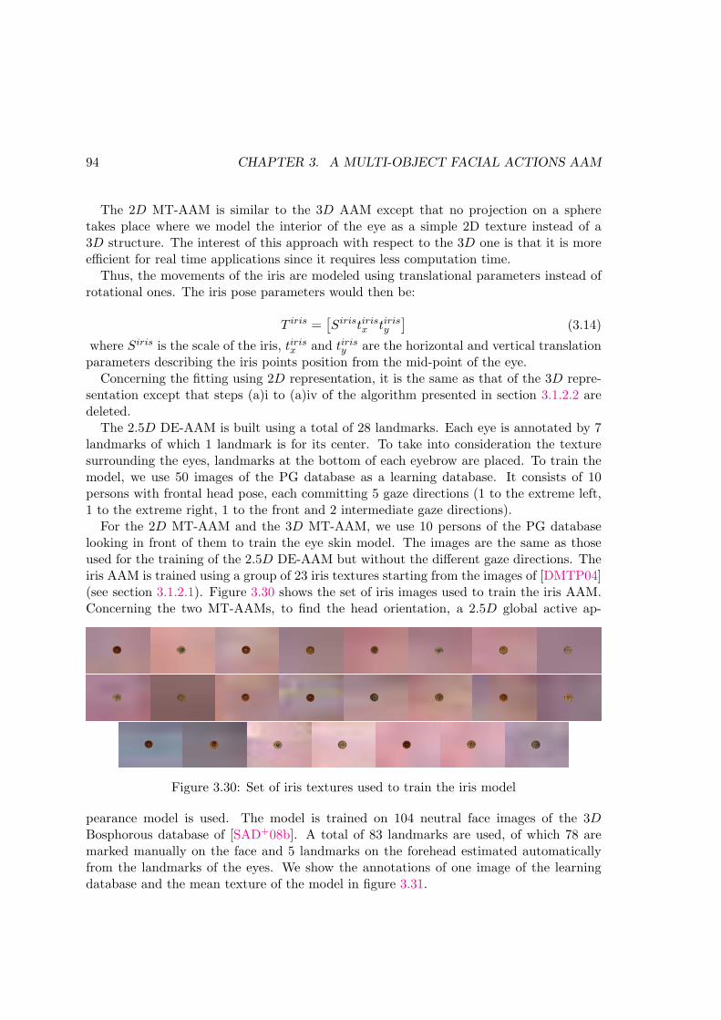
94 CHAPTER 3. A MULTI-OBJECT FACIAL ACTIONS AAM
The 2D MT-AAM is similar to the 3D AAM except that no projection on a spheretakes place where we model the interior of the eye as a simple 2D texture instead of a3D structure. The interest of this approach with respect to the 3D one is that it is moreefficient for real time applications since it requires less computation time.
Thus, the movements of the iris are modeled using translational parameters instead ofrotational ones. The iris pose parameters would then be:
T iris =[
Siristirisx tirisy
]
(3.14)
where Siris is the scale of the iris, tirisx and tirisy are the horizontal and vertical translationparameters describing the iris points position from the mid-point of the eye.
Concerning the fitting using 2D representation, it is the same as that of the 3D repre-sentation except that steps (a)i to (a)iv of the algorithm presented in section 3.1.2.2 aredeleted.
The 2.5D DE-AAM is built using a total of 28 landmarks. Each eye is annotated by 7landmarks of which 1 landmark is for its center. To take into consideration the texturesurrounding the eyes, landmarks at the bottom of each eyebrow are placed. To train themodel, we use 50 images of the PG database as a learning database. It consists of 10persons with frontal head pose, each committing 5 gaze directions (1 to the extreme left,1 to the extreme right, 1 to the front and 2 intermediate gaze directions).
For the 2D MT-AAM and the 3D MT-AAM, we use 10 persons of the PG databaselooking in front of them to train the eye skin model. The images are the same as thoseused for the training of the 2.5D DE-AAM but without the different gaze directions. Theiris AAM is trained using a group of 23 iris textures starting from the images of [DMTP04](see section 3.1.2.1). Figure 3.30 shows the set of iris images used to train the iris AAM.Concerning the two MT-AAMs, to find the head orientation, a 2.5D global active ap-
Figure 3.30: Set of iris textures used to train the iris model
pearance model is used. The model is trained on 104 neutral face images of the 3DBosphorous database of [SAD+08b]. A total of 83 landmarks are used, of which 78 aremarked manually on the face and 5 landmarks on the forehead estimated automaticallyfrom the landmarks of the eyes. We show the annotations of one image of the learningdatabase and the mean texture of the model in figure 3.31.

3.2. TESTS AND RESULTS 95
(a) Annotations (b) Mean texture
Figure 3.31: On the left, the annotations to obtain the head pose model. On the right,the corresponding mean texture
Optimization – Concerning the 2D MT-AAM, a Genetic Algorithm (GA) followedby a Gradient Descent (GD) is used to optimize the iris appearance and pose parameters.Concerning the 3D MT-AAM, only a GA is used for optimization. Concerning the DE-AAM two consecutive Newton gradient descent algorithms are used. In the first one thelearning of the relationship between the error and the displacement of the parameters isdone offline during the training phase as proposed by Cootes [CET98c]. In the second,this relationship is learned online. The parameters from the first optimization scheme areentered into the second in order to refine the results.
Constraints – Since the iris location and scale are constrained by the size of the eye,constraints are added in order to tighten up the search space of the iris pose vector forthe 2 versions of MT-AAM.
2D MT-AAM – Constraints are based on anthropometric averages which give a verytight bound on the size of the iris relative to the size of the eye and on the fact that irismovements have limits imposed on them by the width of the eye. Iris average width isapproximated at 1/1.6 the width of the eye.
3D MT-AAM – The horizontal rotation of the sphere is limited to +40◦ and −40◦
and the vertical rotation is limited to +10◦ and −10◦ which is found to give plausibleprojections of the 3D iris shape.
For both 2D and 3D MT-AAM, the scale is varied around an initial scale calculatedusing the width of the iris and that of the mean iris. The horizontal and vertical trans-lation parameters cannot exceed half of the eye width and height respectively, taking themidpoint of the distance between the eye corners as the origin point.
Testing – We conduct two types of tests. The first test was made on a sample of imagesfrom the PG database. This means that we test on images coming from the database thatwas used for training the models. Of course testing was done on another set of images
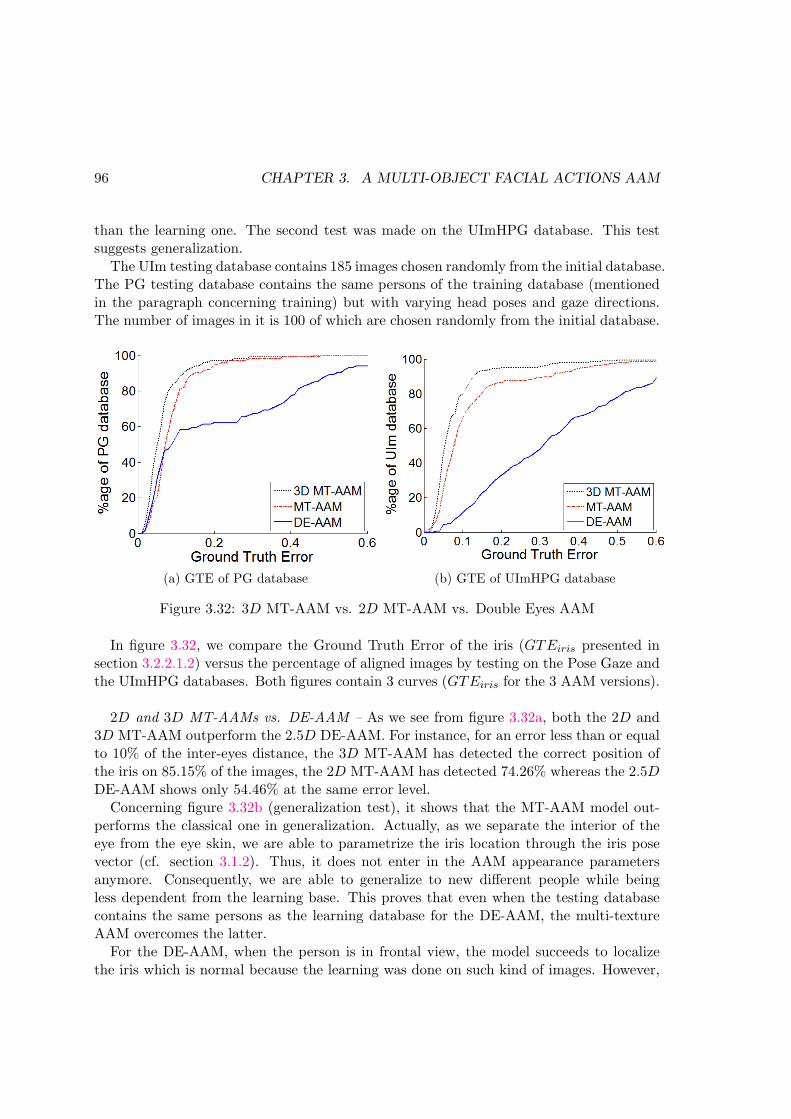
96 CHAPTER 3. A MULTI-OBJECT FACIAL ACTIONS AAM
than the learning one. The second test was made on the UImHPG database. This testsuggests generalization.
The UIm testing database contains 185 images chosen randomly from the initial database.The PG testing database contains the same persons of the training database (mentionedin the paragraph concerning training) but with varying head poses and gaze directions.The number of images in it is 100 of which are chosen randomly from the initial database.
(a) GTE of PG database (b) GTE of UImHPG database
Figure 3.32: 3D MT-AAM vs. 2D MT-AAM vs. Double Eyes AAM
In figure 3.32, we compare the Ground Truth Error of the iris (GTEiris presented insection 3.2.2.1.2) versus the percentage of aligned images by testing on the Pose Gaze andthe UImHPG databases. Both figures contain 3 curves (GTEiris for the 3 AAM versions).
2D and 3D MT-AAMs vs. DE-AAM – As we see from figure 3.32a, both the 2D and3D MT-AAM outperform the 2.5D DE-AAM. For instance, for an error less than or equalto 10% of the inter-eyes distance, the 3D MT-AAM has detected the correct position ofthe iris on 85.15% of the images, the 2D MT-AAM has detected 74.26% whereas the 2.5DDE-AAM shows only 54.46% at the same error level.
Concerning figure 3.32b (generalization test), it shows that the MT-AAM model out-performs the classical one in generalization. Actually, as we separate the interior of theeye from the eye skin, we are able to parametrize the iris location through the iris posevector (cf. section 3.1.2). Thus, it does not enter in the AAM appearance parametersanymore. Consequently, we are able to generalize to new different people while beingless dependent from the learning base. This proves that even when the testing databasecontains the same persons as the learning database for the DE-AAM, the multi-textureAAM overcomes the latter.
For the DE-AAM, when the person is in frontal view, the model succeeds to localizethe iris which is normal because the learning was done on such kind of images. However,

3.2. TESTS AND RESULTS 97
Figure 3.33: Qualitative comparison between the 2D multi-texture approach (rightcolumns) and the DE-AAM approach (left columns).
Figure 3.34: Qualitative comparison between the 3D MT-AAM (upper row of the sameperson) and the 2D MT-AAM (lower row of the same person).

98 CHAPTER 3. A MULTI-OBJECT FACIAL ACTIONS AAM
when it comes to the different head poses present in the testing database, the DE-AAMwill fail while the MT-AAM will not. This is due to the fact that in the DE-AAM it isnecessary to increase the number of images in the learning database to increase the accu-racy and to include variation in pose. Whereas, with the MT-AAM, the number of imagesin the learning database is sufficient to localize accurately the eyelids since the interior isremoved and we have the same persons; then for the iris location, the general iris texturethat is slided under the skin is able to localize it.
2D vs. 3D MT-AAM – As we see from figure 3.32a, the 3D MT-AAM outperforms the2D MT-AAM which confirms the success of modeling the iris as a part of a sphere whichis normal because it is more realistic. Concerning figure 3.32b (generalization test), wehave a good detection of 80% for the 3D MT-AAM versus 65.95 for the 2D MT-AAMand 11.35% for the 2.5D DE-AAM method for the same error level of 10%. This confirmsfirst that the 3D MT-AAM is also better than the 2D MT-AAM in generalization.
We would like to point out that modeling the iris as a part of a sphere instead of aplane permits to give the gaze angle directly. This shows another advantage of a 3Drepresentation over the 2D one. In the latter, the pose of the iris is in terms of verticaland horizontal translations. Thus, to compute the gaze angle, further calculations shouldbe done. We compare these two representations in the results section of this chapter andshow the superiority of the 3D representation over the other.
In addition, figure 3.33 shows qualitative results on the UImHPG database to comparethe MT-AAM and the DE-AAM. As the figure shows, MT-AAM succeeds to follow thegaze of persons with eye glasses and with different head poses, whereas the DE-AAMmethod does not. This assures the fact that with our method we are able to restrict thetraining base where there’s no need to include people wearing eyeglasses in order to getreliable results on such subjects. The reason behind this is that as we divide the eye modelinto two models (eyes skin and iris), the iris model is not disturbed by the glares of theglasses.
On the other hand, figure 3.34 shows some qualitative results comparing the two models:the 3D MT-AAM and the 2D MT-AAM. In addition to the iris center, we show the irisshape on these images to show the difference between these two models in this aspect. Itis obvious from the figure the superiority of the 3D AAM on the 2D AAM. As we seefor extreme gaze directions the iris in the 3D MT-AAM will take the shape of an ellipserepresenting realistically its appearance, however for the 2D MT-AAM, the iris shape isa circle that comes out of the eye in most of the times because it can not take the realshape of the iris. As a conclusion, we can state that the 3D representation of the iris ismore realistic than a 2D one and thus gives better results.
3.2.2.5 Comparison with a state-of-the-art method
This part compares the 3D MT-AAMmethod to the state-of-the-art method of [HSL11].The comparison is conducted on 3 image sequences of the UImHPG database (heads 3, 12
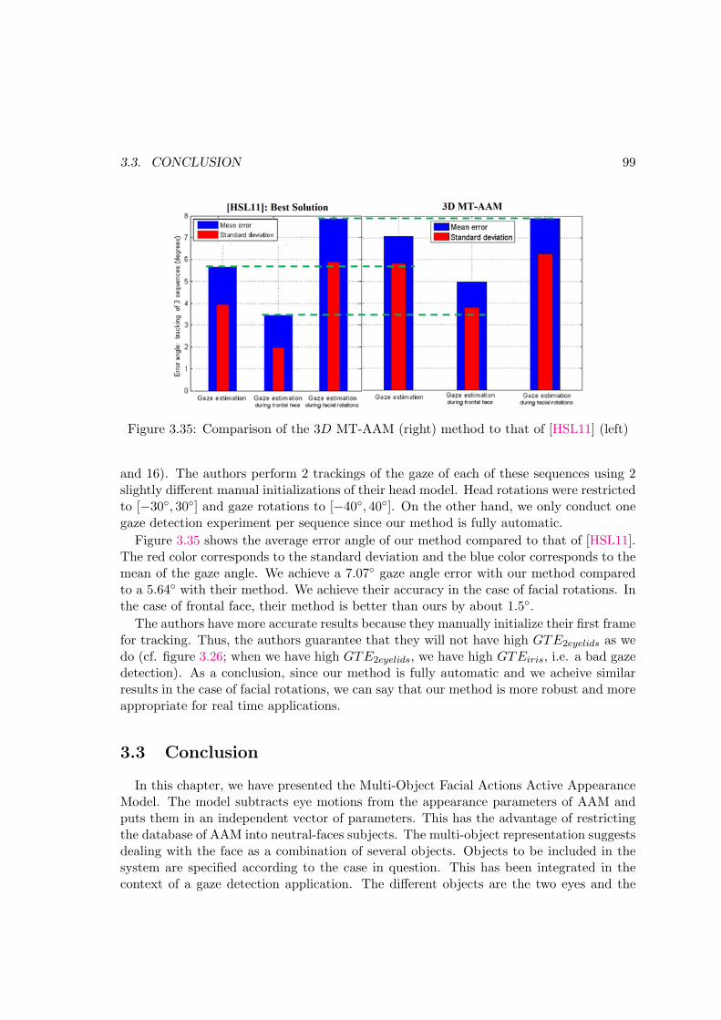
3.3. CONCLUSION 99
Figure 3.35: Comparison of the 3D MT-AAM (right) method to that of [HSL11] (left)
and 16). The authors perform 2 trackings of the gaze of each of these sequences using 2slightly different manual initializations of their head model. Head rotations were restrictedto [−30◦, 30◦] and gaze rotations to [−40◦, 40◦]. On the other hand, we only conduct onegaze detection experiment per sequence since our method is fully automatic.
Figure 3.35 shows the average error angle of our method compared to that of [HSL11].The red color corresponds to the standard deviation and the blue color corresponds to themean of the gaze angle. We achieve a 7.07◦ gaze angle error with our method comparedto a 5.64◦ with their method. We achieve their accuracy in the case of facial rotations. Inthe case of frontal face, their method is better than ours by about 1.5◦.
The authors have more accurate results because they manually initialize their first framefor tracking. Thus, the authors guarantee that they will not have high GTE2eyelids as wedo (cf. figure 3.26; when we have high GTE2eyelids, we have high GTEiris, i.e. a bad gazedetection). As a conclusion, since our method is fully automatic and we acheive similarresults in the case of facial rotations, we can say that our method is more robust and moreappropriate for real time applications.
3.3 Conclusion
In this chapter, we have presented the Multi-Object Facial Actions Active AppearanceModel. The model subtracts eye motions from the appearance parameters of AAM andputs them in an independent vector of parameters. This has the advantage of restrictingthe database of AAM into neutral-faces subjects. The multi-object representation suggestsdealing with the face as a combination of several objects. Objects to be included in thesystem are specified according to the case in question. This has been integrated in thecontext of a gaze detection application. The different objects are the two eyes and the

100 CHAPTER 3. A MULTI-OBJECT FACIAL ACTIONS AAM
head pose plays the role of the criterion that specifies which object contributes the mostin the gaze detection system.

Chapter 4
Face modeling for emotionrecognition
Sommaire
4.1 The Facial Expression Recognition and Analysis Challenge . . 102
4.1.1 System overview . . . . . . . . . . . . . . . . . . . . . . . . . . . 104
4.1.1.1 Hybrid-features Action Unit detection system . . . . . 105
4.1.2 Active Appearance Models coefficients . . . . . . . . . . . . . . . 107
4.1.3 Results . . . . . . . . . . . . . . . . . . . . . . . . . . . . . . . . 109
4.1.3.1 AAM results . . . . . . . . . . . . . . . . . . . . . . . . 109
4.1.3.2 IMMEMO team challenge results . . . . . . . . . . . . . 112
4.2 The Audio/Visual Emotion Challenge . . . . . . . . . . . . . . . 116
4.2.1 Global system . . . . . . . . . . . . . . . . . . . . . . . . . . . . . 117
4.2.1.1 Relevant features extraction . . . . . . . . . . . . . . . 117
4.2.1.2 Training Process . . . . . . . . . . . . . . . . . . . . . . 120
4.2.1.3 Fusion of relevant features . . . . . . . . . . . . . . . . 121
4.2.2 Facial Features detection: The Multi-model AAM . . . . . . . . 121
4.2.2.1 Proposition . . . . . . . . . . . . . . . . . . . . . . . . . 122
4.2.2.2 Results of the MM-AAM . . . . . . . . . . . . . . . . . 125
4.2.3 Emotion detection results . . . . . . . . . . . . . . . . . . . . . . 126
4.3 Conclusion . . . . . . . . . . . . . . . . . . . . . . . . . . . . . . . 128
The face is the key to understanding emotion, and emotion is the key to un-derstanding the face.
– J. A. Russel, and J.M. Fernandez-Dols The psychology of facial expression
The nature of the Human-Human interaction is multi-modal. When two people inter-act with each other, they interact through their faces (in the form of facial expressions),
101

102 CHAPTER 4. FACE MODELING FOR EMOTION RECOGNITION
through their voices (tonality), through their conversations (spoken words), body move-ments and posture, hand gesture, head pose, and their eyes (gaze). Through this interac-tion, they communicate their internal emotions. This makes evidence that the nature ofemotion perception is multi-modal.
Perhaps facial expression is the cue that reveals emotion the most because a personexpression is easier to interpret than the other cues and because expressions are closelytied to emotion. For example, if a person is happy, he will tend to smile without a doubt.This is why automatic recognition of human emotion has focused on facial and vocalemotion interpretation in terms of six basic emotions [E+93] which are tied to particularfacial expressions: neutral, sadness, happiness, fear, anger, surprise and disgust. FacialAUs [EF77] detection was also abundantly used in a categorical approach of emotioninterpretation. However, researchers have argued that the interpretation of emotion withrespect to six limited independent emotions is not enough to describe the complex andsubtle nature of emotion.
This gave birth to other axes of emotion interpretation: the dimensional approach andthe appraisal-based approach. The dimensional approach interprets emotions in termsof some continuous dimensions in an affect space. In this approach emotions are notindependent from each other and relate to one another by these dimensions.
The Facial Expression Recognition and Analysis Challenge (FERA 2011) and Au-dio/Visual Emotion Challenge (AVEC 2012) are two challenges that have one of theirobjectives to provide a common benchmark testing set for emotion detection. FERA 2011considers the categorical approach of emotion detection where two sub-challenges whereorganized concerning discrete emotions and AUs detection. Only video data where consid-ered, thus the challenge is uni-modal. On the other hand, the AVEC 2012 generalizes tothe use of multi-modal cues in the detection of emotion using the dimensional approach.
These challenges were a chance for us to test our feature detection skills using ActiveAppearance Models on real naturalistic data. They also permit us to employ our featuredetection capabilities in automatic emotion detection which is a very active and importantsubject to Human Computer Interface and human psychology.
In the following sections, we present each of the two challenges and the data that weworked on. We describe the systems that we have employed and how we have adaptedour skills in facial features detection using AAMs in these challenges. We specify ourcontributions at the levels of the systems creation and facial features detection. Section 4.1is dedicated to the FERA 2011 challenge and section 4.2 describes the FERA 2012.
4.1 The Facial Expression Recognition and Analysis Chal-lenge
The Facial Expression and Analysis challenge (FERA 2011) [VJM+11] is the firstchallenge in automatic recognition of facial expressions organized in conjunction with theIEEE International conference on Face and Gesture Recognition 2011. The objective of

4.1. THE FACIAL EXPRESSION RECOGNITION AND ANALYSIS CHALLENGE103
the challenge is to provide a common data set where participants compete and comparetheir methods.
The challenge is divided in two sub-challenges that reflect two popular approaches tofacial expression recognition: an AU detection sub-challenge and an emotion detectionsub-challenge. The AU detection sub-challenge calls for researchers to attain the highestpossible F1-measure for 12 frequently occurring AUs (cf. figure 4.1). The emotion detec-tion sub-challenge calls for systems to attain the highest possible classification rate for thedetection of five discrete emotions: anger, fear, joy, relief, and sadness.
Figure 4.1: The Action Units to be detected for the FERA 2011 challenge
In the framework of IMMEMO ANR project (IMMersion 3D basee sur l’interactionEMO tionnelle) [IMM], we have participated in the AU detection sub-challenge in collab-oration with the ISIR, LAMIA and LTCI teams and took the first place [SRS+11]. Theproposed method was later tested for emotion detection and gave results that are veryclose to those who won the second sub-challenge [YB11].
The challenge uses a partition of the GEMEP corpus [BS07] developed by the GenevaEmotion Research Group (GERG) at the University of Geneva led by Klaus Scherer. Thisdatabase presents a number of professional actors performing 18 emotions. For the AUsub-challenge, the database is split into two partitions: a training partition consisting of 87videos and a test partition consisting of 71 videos. For the emotion sub-challenge, a totalof 289 videos were selected (155 for training and 134 for testing). For both sub-challenges,the training set includes 7 actors and the test set includes 6 actors, half of which were notpresent in the training set.
The difficulty of this database is that the expressions displayed by the actors are spon-taneous and natural. Speech is included which results in more variability in the lower partof the faces in the database (actors pronounce meaningless phrases or the word ”aaah”).In addition, actors are not posed, in contrary they act naturally and move their facesfreely. Figure 4.2 shows some examples of the images of this database.

104 CHAPTER 4. FACE MODELING FOR EMOTION RECOGNITION
Figure 4.2: Examples of some images of the GEMEP-FERA dataset
4.1.1 System overview
AU detection can be classified into three categories: appearance feature-based [BLF+06],geometric feature-based methods [SLS+07, VP06] and hybrid features methods. Appear-ance feature-based methods extract features that try to represent the facial texture suchas wrinkles, bulges and furrows. Geometric-based methods extract the facial shape andthe location of facial points. Hybrid methods combine both features [CLL+11a, ZJ05a].
We propose an AU detection system that belongs to the hybrid features family. Itcombines appearance features in the form of Local Gabor Binary Pattern histograms andgeometric features in the form of Active Appearance Models appearance parameters.
In the following, first we briefly describe the overall system of AU detection proposedby our team, along with the different techniques used (section 4.1.1.1). Then we detailour contribution at the level of extraction of AAM coefficients (section 4.1.2). Finally, wepresent the results of the challenge and we show how the AAM coefficients contribute toincreasing the overall results (section 4.1.3).

4.1. THE FACIAL EXPRESSION RECOGNITION AND ANALYSIS CHALLENGE105
4.1.1.1 Hybrid-features Action Unit detection system
�����
���� ���� �
������������ �������� �
� ���� �������� �
������������� � ����
���� � ������
����� ������� ������ ���
�������������� ���������
���������� ������� ������ ���
�� ��!�� ������
������� ���� �������"#����� $%�
&��� ������������
�'������������ �
�����������
��� ����
�� ��� ��
���������� ��
Figure 4.3: Global system of AU detection
Automated facial expression recognition is generally accomplished by four steps:
1. Preprocessing and that includes face detection and landmark localization;
2. Image coding, and that is feature vectors extraction;
3. Classification of the image as a positive sample (an AU, several AUs or an emotionis present in the image) or a negative sample;
4. Temporal analysis;
Figure 4.3 presents the flow chart of our global system for AU detection.Preprocessing – First eyes are detected using the feature localizer of [RSBP11] based
on multiple kernel SVM learning. Eyes centers are then used to: 1) normalize the imagewith respect to scale, position and in-plane rotations variations and with respect to theimage size. This is used for the appearance-based features extraction; 2) Apply Active

106 CHAPTER 4. FACE MODELING FOR EMOTION RECOGNITION
Appearance Models to the test images to extract the facial feature points (see the followingparagraph).
Features extraction –Two types of features are extracted in our AU detection system: Appearance features
in the form of Local Gabor Binary Pattern (LGBP) histograms introduced by [ZSG+05]and hybrid features in the form of Active Appearance Models (AAM) coefficients (AAMscombine geometric and appearance features).
Appearance features: LGBP histograms – The normalized images are used to calculateLGBP histograms. The interest of such features is that they exploit the multi-resolutionand the multi-orientation links between pixels. In addition, they are known to be robustto illumination changes and misalignments. LGBP are computed in the following manner.
Figure 4.4: Local Gabor Binary Pattern histograms computation
1. Compute the Gabor magnitude pictures by convolving the facial image with Gaborfilters: Three spatial frequencies were used and six orientations for a total of 18Gabor filters. Only the magnitude was kept since the phase is very sensitive. Thisresults in 18 Gabor magnitude pictures.
2. Compute the Local Binary Pattern (LBP) for each of the 18 Gabor magnitudeimages.
3. Divide the face into n×n areas and compute a histogram per area. This accounts forthe different useful information for the AUs contained in the different facial regions.
4. Concatenate all the histograms in the feature vector Hi after reducing the numberof bins in each histogram [SRS+12].
Hybrid features: AAM coefficients – The extraction of AAM coefficients is presented insection 4.1.2. The importance of AAM for this system is that they can provide importantspatial information of key facial landmarks. Thus, it compensates the loss of spatialinformation which really depends on identity when using just LGBP histograms.

4.1. THE FACIAL EXPRESSION RECOGNITION AND ANALYSIS CHALLENGE107
Classification – The proposed AU detection system uses Support Vector Machines(SVM) for their ability to find an optimal separating hyper-plane between the positive andnegative samples in binary classification problems. As both features (LGBP histogramsand AAM coefficients) are very different, they were not concatenated in a single featurevector. Instead of using one single kernel function, two different kernels were used, oneadapted to LGBP histograms and the other to AAM coefficients. These kernels werecombined in a multi-kernel SVM framework [RBCG08]. In our case, we have one kernelfunction per type of features.
K = β1KLGBP (Hi, H) + β2KAAM (Ci, C) (4.1)
β1 represents the weight accorded to the LGBP features and β2 is the one for the AAMappearance vector. Thus, using a learning database, the system is able to find the bestcombination of these two types of features that maximizes the margin.
KLGBP and KAAM are the kernel functions for the LGBP histograms and the AAMcoefficients respectively where for the LGBP histograms, histogram intersection kernel wasused and for the AAM appearance vectors, the Radial Basis Function (RBF) kernel wasused:
KLGBP (Hi, Hj) =∑
k
min(Hi(k), Hj(k))KAAM (Ci, Cj) = e−‖si−sj‖
2
2
2σ2 (4.2)
With σ a hyper-parameter we have to tune on a cross-validation database.This is a new way of using multi-kernel learning. Instead of combining different kinds of
kernel functions (for example Gaussian radial basis functions with polynomial functions),we combine different features.
The AAMs modeling approach takes the localization of the facial feature points intoaccount and leads to a shape-free texture less-dependent to identity. However, one ofthe severe drawbacks is the need of a good accuracy for the localization of the facialfeature points. The GEMEP-FERA database contains large variations of expressions thatsometimes lead to inaccurate facial landmarks tracking. In such cases, multi-kernel SVMswill decrease the importance given to AAM coefficients.
4.1.2 Active Appearance Models coefficients
Even though we have worked on the global system with the team, our principal contri-bution focused on AAM coefficient generation.
4.1.2.0.1 AU detection: 2.5D AAM local models
As AUs are elementary muscle movements that affect small different regions in the face,and due to the fact that the AUs to detect are divided into two parts: the upper AUs andthe lower ones, we decide to employ two 2.5D AAMs [SALGS07b] local models: one forthe mouth and one for both eyes.

108 CHAPTER 4. FACE MODELING FOR EMOTION RECOGNITION
Figure 4.5: Landmarks for the eyes and mouth models
In local models, the shapes and textures of the eyes are not constrained by the corre-lation with the shape and texture of the mouth, and thus, local AAM’s are supposed togive more precise results than a global one for local areas. More precisely, if the testingimage does not present the same correlation between the eyes and the mouth as the onespresent in the learning base, based on our experiments, a global model will probably failto converge while the local one will not.
Training – The mouth sub-model is formed of 36 points which contain points from thelower part of the face and from the nose shape. The eyes sub-model contains both eyesand eyebrows with 5 landmarks on the forehead which are estimated automatically fromthe landmarks of the eyes resulting in 42 landmarks (Fig. 4.5).
Testing – To optimize the appearance parameters of both eyes and mouth AAMs,we employ two consecutive Newton gradient descent algorithms. The difference betweenthe two is that in the first one the learning of the relationship between the error andthe displacement of the parameters is done off-line during the training phase as proposedby Cootes [CET98b], while in the second one we evaluate this relationship on line. Theobtained parameters from the first optimization scheme are entered into the second inorder to refine the results.
4.1.2.0.2 Emotion detection: Global skin model
For emotion recognition we use a different model to obtain the AAM coefficients. Wetrain a global model and not two local models as it is the case for the AU detection part.After trying the local models and a global model for the AU recognition (a global modelwas applied for the original results of the FERA challenge [SRS+11]), we observed thatthe interior of the eyes and that of the mouth add misleading variations to the AAM.Actually, the appearance of the eye undergoes many variations due to the scale, color,position of the iris and that of the mouth changes where the teeth and tongue may appearor disappear as the person speaks. This can be confirmed by the tests that compare

4.1. THE FACIAL EXPRESSION RECOGNITION AND ANALYSIS CHALLENGE109
dans asrtraining3D
10 20 30 40 50 60
10
20
30
40
50
60
Figure 4.6: Mean texture of the global skin model: holes are put in place of the interiorof the eyes and the mouth.
the eyes models with and without holes in the previous chapter (section 3.2.2.1.1, figure3.24). Consequently, when the interior of the eyes and the mouth are learned with themodel, this increases the number of appearance parameters and introduces unnecessaryvariations. So, we decide to remove their perturbation to the appearance of the face byputting holes in their place while training the model. We call this model the global skinAAM, since only facial skin information was used.
Training – We use a total of 83 landmarks to train this AAM. Figure 4.6 is an illus-tration of the mean texture of this model.
Testing – To obtain the test appearance parameters, for every sequence in the FERAemotion database, we launch the tests in tracking mode. For every first image of everysequence, force is put to have a good fitting result and then for the rest of the imagesin the sequence, the model uses the appearance parameters of the preceding image andadapts itself to the current image with less number of iterations. As for the optimization,the same scheme as that with the AU recognition model is used.
4.1.3 Results
4.1.3.1 AAM results
AU detection – AAM local models were trained on a total of 466 expression and neu-tral images from the Bosphorous 3D face database [SAD+08a]. This suggests a pure AAMgeneralization. Figure 4.7 shows some results of the mouth and local eyes AAM fitting.As we see, for all the images, the localization of the mouth is successful which confirmsthe efficiency of using a local model for the mouth. Concerning the eyes localization bythe eyes local AAM, the figure shows that all the eyes of the images are precisely localizedexcept for the last image. The reason is that for this image the eyes sub-model takes into

110 CHAPTER 4. FACE MODELING FOR EMOTION RECOGNITION
LBPLGBP
Eyes Mouth Both LGBP LGBP LGBP(baseline) AAM AAM AAMs +Eyes +Mouth +Both
AAM AAM AAMs
upper AU
AU1 79.0 78.8 60.5 54.4 62.3 77.6 81.8 80.3AU2 76.7 77.1 57.4 51.3 57.4 57.0 83.4 82.7AU4 52.6 62.9 62.0 56.4 59.3 62.4 61.3 58.5AU6 65.7 77.0 56.4 75.8 80.9 79.3 80.9 81.0AU7 55.6 68.5 67.8 54.3 54.4 72.5 71.0 71.2
lower AU
AU10 59.7 51.9 43.2 56.3 51.9 49.9 52.7 52.1AU12 72.4 79.9 63.9 69.9 79.5 81.7 82.3 82.2AU15 56.3 63.0 58.3 68.7 71.2 67.1 59.6 61.4AU17 64.6 65.8 51.9 67.1 66.3 67.2 72.5 70.7AU18 61.0 70.4 51.9 75.3 75.8 54.8 79.0 78.5AU25 59.3 59.8 55.6 69.6 63.6 56.0 63.5 65.6AU26 50.0 64.3 57.0 67.5 58.6 58.7 64.8 62.9
Avg 63.1 67.8 57.4 63.6 65.5 65.5 71.6 71.5person-specific
Avg 61.1 68.0 57.4 65.3 66.1 65.9 69.5 69.0person-indep.
Avg overall 62.8 68.3 56.8 63.9 65.1 65.3 71.1 70.6
Table 4.1: 2AFC scores on the GEMEP-FERA test dataset using LGBP, eyes AAMcoefficients, mouth AAM coefficients, concatenation of the eyes AAM coefficients and themouth AAM coefficients and the fusion of LGBP with AAM coefficients.

4.1. THE FACIAL EXPRESSION RECOGNITION AND ANALYSIS CHALLENGE111
Figure 4.7: AAM local models results on some test images showing successful eyes andmouth segmentation except for the last image where hair perturbation mislead the eyesmodel.
Figure 4.8: AAM global skin model results on some test images showing successful eyesand mouth segmentation. See how for the third image, the hair perturbation does notaffect the eyebrows localization taking advantage of a global model and a holes approach
consideration the forehead texture, cf. figure 4.5, which is covered with hair (perturba-tion) in this testing image. A local model would work in such a case only if the trainingdatabase contained subjects having same kind of hair on their foreheads. However, this isnot the case here. This shows one disadvantage of local models with respect to global ones.As a matter of fact, in a global model the amount of error becomes relatively smaller inlocal areas having perturbations. In addition, a global model will make use of correlationsbetween the different parts of the face and thus it will have more tendency than a localmodel to converge in such cases. This was shown in the context of AVEC 2012 challengethat we later participated in.

112 CHAPTER 4. FACE MODELING FOR EMOTION RECOGNITION
Emotion detection – The global skin AAM was trained on 598 images from the CohnKanade and the Fera databases (258 images). Although it is not our objective to comparethe behavior of the global skin AAM and that of local models, it seems interesting to showthe result of the global skin AAM on the same subject where the local eyes AAM did notwork. Figure 4.8 presents this result together with some results on other images.
4.1.3.2 IMMEMO team challenge results
For the experiments, the following databases are used as training databases:
– The Cohn-Kanade database [KCT00]: the last image (expression apex) of all the 486sequences. It contains images sequences of 97 university students ranging from agesof 18-30. The lighting conditions and context are relatively uniform and the imagesinclude small in-plane and out-plane head motion.
– The Bosphorus database [SAD+08a]: around 500 images chosen because they exhibita combination of two AUs. The lighting conditions and context are relatively uniformand the images include small in-plane and out-plane head motion.
– The GEMEP-FERA training dataset [BS07]: one frame from every sequence for everyAU combination present resulting in 600 images.
The SVM slack-variable and the RBF kernel parameter were optimized using a 7-foldsubject independent cross-validation on all the GEMEP-FERA dataset. All the images ofone subject from the GEMEP-FERA training dataset are used as a test set (around 800images). Images of the other subjects within the 600 selected from the GEMEP-FERAtraining dataset, and eventually from other databases, are used as a training dataset.
4.1.3.2.1 Effect of combining features – In this section, we prove that fusingLGBP histograms with AAM coefficients gives the best results for the AU detection.To do this, we report the area under the ROC curve for the different features and theircombinations: by using the signed distance of each sample to the SVM hyper-plan andvarying a decision threshold, we plot the hit rate (true positives) against the false alarmrate (false positives). The area under this curve is equivalent to the percentage of correctdecisions in a 2-Alternative Forced Choice task (2AFC) by which the system must choosewhich of the two images contains the target.
The system is trained on the GEMEP-FERA training dataset. We compare the 2AFCof our system to that of the baseline for: person independent (test subjects are not inthe training database), person specific (test subjects are in the training database) andoverall. We report in Tab. 4.1 the overall results for each AU and the average for theperson specific, person independent and overall case.
Using only LGBP, we notice that we already have better results than the baselineproposed by the organizers (68.3% against 62.8% overall). The two methods are reallysimilar: equivalent setup, same training database, same classifier, only the features andthe kernel function of the SVM are different.

4.1. THE FACIAL EXPRESSION RECOGNITION AND ANALYSIS CHALLENGE113
Using only the AAM appearance vector, we notice that we have good results using themouth AAM to detect the AUs localized in the lower part of the face. Results are evenbetter than LGBP for the AUs 15, 17, 18, 25 and 26 (68.7% 67.1% 75.3% 69.6% and67.5% against 63% 65.8% 70.4% 59.8% and 64.3% respectively). Results obtained for theupper part of the face are obviously not of a big importance (close to a random classifier’sresponse) using mouth information. Only the AU 6 is well detected. This is because thisAU (cheek raiser) often appears with the AU12 (the smile). With eyes AAM, results arejust slightly better than random classifiers (56.8% where a random system does 50%).This can be explained by the difficulty in fitting AAM with enough accuracy to detectAUs. The eyebrows, for example, are difficult to localize, especially when hair hides them.
Regarding the fusion, we notice that the eyes AAM does not increase performances ifcoupled with LGBP histograms. But the mouth AAM or both AAMs coupled with LGBPslead to the best results. Surprisingly, the detection of the upper part face AUs is improvedwith the mouth AAM: 81.8%, 83.4%, 80.9% 71.0% for the AUs 1 2 6 and 7 respectivelyagainst 78.8% 77.1% 77.0% and 68.5% with LGBP only. As previously mentioned, theimprovement for the AU 6 can be explained by the fact that this AU is related to the AU12. However the improvement brought by the fusion for the other AUs is more difficult tointerpret. The multi-kernel classifier may use the information given by the mouth AAMnot to directly detect these upper part AUs, but to have information about the subject(for example, information about its identity, skin type...) that can help the classifier tobetter analyze LGBP features and increase the precision of the AUs detection. This showsthe interest of combining two types of different features.
Overall, the fusion of both AAMs with LGBP increases experimental results significantlyfor 9 over 12 AUs, the AUs 1 2 6 7 12 17 18 and 25. Results are worst only for one AU,the AU 15.
Finally, if we compare results in the person-specific and person-independent cases, wenotice that the fusion is better than using only one feature type. In both cases, we getthe highest 2AFC scores when combining LGBP with the mouth AAM: 71.6% for theperson-specific case and 69.5% for the person-independent one). Combining with bothAAMs gives approximately equal results to those obtained by combining with the mouthAAM: 71.5% for the person-specific case and 69.0% for the person-independent case.
4.1.3.2.2 Comparison with the other participants – To compare the partici-pants’ results in the AU sub-challenge, the F1-measure was used. The F1-measure con-siders both the precision p and the recall r of the test results to compute the score: p isthe number of correct detections divided by the number of all returned detections and ris the number of correct detections divided by the number of detections that should havebeen returned. The F1-measure can be interpreted as a weighted average of the precisionand recall, where an F1-measure reaches its best value at 1 and worst score at 0. TheF1-measure is used only to optimize the part of the system converting signed values tobinary values (size of the average filter and thresholds).

114 CHAPTER 4. FACE MODELING FOR EMOTION RECOGNITION
Figure 4.9: FERA AU sub-challenge official F1 results of all participants. UCSD: Univer-sity of San Diego [WBR+11]. KIT: Karlsruhe Institute of Technology. QUT: QueenslandUniversity of Technology [CLL+11b]. MIT-Cambride : Massachusetts Institute of Tech-nology and University of Cambridge [BMB+11].
F = 2 ·p · r
p+ r(4.3)
The F1 scores obtained this way during the challenge and those of all participants arereported in Fig. 4.9. The system described in this thesis outperformed all other systemsin the person independent and in the person specific case.
Classifiers were trained with the GEMEP-FERA, CK and Bosphorus databases for theAUs 1 2 4 12 15 17. We exclude the Bosphorous database for the training of the otherAUs since these do not exist in this database.
If the reader is interested in the comparison between the different participants, he canrefer to the paper of [SRS+11].
As a conclusion, we can state that by combining AAM features and LGBP featurestogether with the use of temporal information, we succeed at overcoming the differentapproaches of the baseline and the other participants.
4.1.3.2.3 Emotion recognition results – Even though we have not participated inthe emotion detection sub-challenge of FERA 2011, however, we have adapted our AUclassifier to this task afterwards [SRS+12]. Table 4.2 reports the results of classificationof the five emotions: Anger, fear, joy, relief and sadness. The overall results are comparedto those of the emotion detection challenge, this is shown in the figure 4.10. As the figure

4.1. THE FACIAL EXPRESSION RECOGNITION AND ANALYSIS CHALLENGE115
Figure 4.10: FERA emotion sub-challenge official F1 results of all participants. UCSD:University of San Diego [WBR+11]. KIT: Karlsruhe Institute of Technology. QUT:Queensland University of Technology [CLL+11b]. MIT-Cambride : Massachusetts In-stitute of Technology and University of Cambridge [BMB+11].
shows, our results come in the second place which confirms that our system is flexible todeal with a different kind of data.
PI PS Overall
Anger 92.9 100 96.3Fear 46.7 90 64Joy 95 100 96.8Relief 75 100 84.6Sadness 60 100 76
Average 73.9 98 83.5
Table 4.2: Our team’s emotion recognition classification rates on the testing database. Weshow performance for the Person-Independent (PI) case, Person-Specific (PS) and overallpartition.

116 CHAPTER 4. FACE MODELING FOR EMOTION RECOGNITION
4.2 The Audio/Visual Emotion Challenge
AVEC 2012 [SVCP12] is the second International Audio-Visual Emotion recognitionchallenge. The goal of the challenge is to recognize four continuously valued affective di-mensions [FSRE07]: arousal, valence, power, expectancy. Arousal is the dimension thatindicates if the person is passive or active, valence shows if the person is pleasant or un-pleasant, power is an indication of power versus weakness, and expectancy signifies noveltyand unpredictability compared with expectedness or familiarity. It is constituted of twosub-challenges: The Fully Continuous Sub-Challenge and the Word-Level Sub-Challenge.We have participated in the Fully Continuous Sub-Challenge where the objective is to pre-dict the values of the four dimensions at every moment during the recordings of a numberof videos. This challenge is the first of its kind to call for the use of different modalities(audio, video, lexical and contextual) or their combination to detect emotion.
The challenge uses a part of the SEMAINE database [MVCP10] which presents natu-ralistic video and audio of human-agent interactions. It involves a user interacting withemotionally stereotyped characters. For the recordings, the participants are asked to talkin turn to four emotionally stereotyped characters. These characters are Prudence, who iseven-tempered and sensible; Poppy, who is happy and outgoing; Spike, who is angry andconfrontational; and Obadiah, who is sad and depressive.
Figure 4.11: Some examples of the SEMAINE database used in the context of AVEC 2012.
The difficulty of this challenge is primarily due to the nature and amount of datathat should be dealt with. Actually, a big amount of unsegmented, non-prototypicaland non preselected videos presenting subjects with naturalistic behavior is to be testedon. Figure 4.11 shows some images of the database. Three partitions of a part of theSEMAINE database are used: a training, development, and test partition, each consistingof 8 recordings of 8 different users. The training partition contains 31 sessions, while thedevelopment and test partitions contain 32 sessions. Test is done on subjects that can notbe present in the training database.
12 participants from the communities of acoustic audio analysis, linguistic audio anal-ysis and video analysis competed to win this challenge. Immemo has sent two teams ontwo different methodologies to participate in this challenge. These teams took the firstand the second place. We were on the second team in collaboration with Dynamixyzand TelecomParisTech. We present a multi-modal system that extracts and merges vi-sual, acoustic and context relevant features. Since our team works in video analysis, this

4.2. THE AUDIO/VISUAL EMOTION CHALLENGE 117
challenge was a chance for us to explore the audio and context domains and to employour video analysis skills for the treatment of real data. Our major contribution was inthe extraction of visual features in the form of laugh variations. This extraction is basedon what we call the ”Multi-Model AAM” (MM-AAM). In the following, we describe ourglobal system (section 4.2.1). We detail our contribution at the level of facial featuresextraction using the MM-AAM (section 4.2.2).
4.2.1 Global system
The system takes as input a number of relevant features, fuses them using a fusionmethod and gives as output the four emotional dimensions (cf. figure 4.12).
Figure 4.12: Overall view of the proposed method: a fuzzy inference system transformsthe relevant features from video, audio and context into 4 emotional dimensions.
4.2.1.1 Relevant features extraction
To choose what features to extract and which are relevant, visual analysis of the videosand the ground truth emotional labels of the training and development databases (annota-tions of raters using FEELTRACE [CDCS+00]) was performed. By noticing which facialgestures and which audio characteristics where the most influencing on the ground truthlabels of videos, we have revealed the most relevant features. The chosen features werethose that explain the global trend of the emotion dimensions and not the small subtlevariations of the emotions. They can be classified into:

118 CHAPTER 4. FACE MODELING FOR EMOTION RECOGNITION
���������
������
���������
����� ���� �����
� ����� ���� � ��������
����������� ������� ���� ���
����������
�������������
����� �����
����� ������
������ �� �
�����
�������������� ������� �����
�������
�� �� ���
�����
�� ��
�����
Figure 4.13: Sources of the relevant features: video files, speech transcripts and emotionallabels.
– video features, that include facial expressions (especially laughter) and body language(especially head gesture);
– audio features, that include speaking turns and speech rate;– context features, that include the emotional agent of the conversation (agent’s nameor emotional words that are said during the conversation), the response time of therater and the conversation time.
The features extraction is made from 3 different data sources : videos, speech transcriptsand ground truth labels (see figure 4.13).
Audio features – From speech transcripts, information about the speaking turns andthe speech rate were extracted.
Speaking turns – The analysis of the sentences gives the length of the sentences pro-nounced by the subject. In our system, we use binary information. For each speakingturn in a conversation, if the number of words pronounced by the subject is high (above35 words, empirical data learnt on training and development databases), the sentence islong ; otherwise, the sentence is short.
Speech rate – The speech rate is computed from the transcripts by the rate: number ofwords by time unit.
Context features Context features include information about the agent that is beingspoken with (empathy), the response time of the rater and the signal structure.
Empathy – The conversations are performed between a subject and an emotional agent,which is set in one of the four quadrants of arousal-valence space (Spike is aggressive;Poppy is cheerful; Obadiah is gloomy; and Prudence is pragmatic).

4.2. THE AUDIO/VISUAL EMOTION CHALLENGE 119
In consequence, we remark the effect of the emotional agent on the emotion displayedby the subject. This can be translated by empathy. That is, the propagation of one’semotion to the other. For example, if the agent is Poppy, then the subject speaking toPoppy has a tendency to display behaviors of high valence and high arousal.
To find automatically which is the emotional agent of the sequences, we extract namesfrom keywords detected from the speech transcripts. They provide some contextual infor-mation on which emotional agent the subject is speaking to.
Response time of the rater – The analysis of the ground truth labels highlights a delayin the start of annotations. This may be due to the initialization of the tool used to rateand to the response time of the rater, so that the first seconds of the ground truth labelsmay not be representative of the subject’s emotion. Consequently, for the challenge, wemodeled this behavior with a feature as a decreasing linear function on the first 20 secondsof the conversation.
Video features – Our main contribution involved the video features extraction. Fromthe video files, body language and facial expressions were found to be the most relevantto the detection of the emotional dimensions.
Body language – We computed the global movement of the head pose in the scene.The video data are analyzed using a person-independent AAM [CET98b] built on thetraining and development databases. In the test phase, the pose parameters of the faceare computed from the AAM model. The body movement is computed from the standarddeviation of the head pose in a video sequence with a sliding temporal window of 40seconds. The more the subject moves and makes wide movements, the higher this quantityis.
Laughter detection – In order to detect the facial expression, the system of [SSS12]was adopted. Actually, the work in this part of the system was divided into two. Thefirst concerned the extraction of the video features and the second concerned the laughterdetection. My principal contribution took place in the first part.
The overall process of laughter detection consists of four steps. First, facial featuresdetection is performed using a Multi-Model person-independent AAM of which was mymajor contribution (section 4.2.2). Second, a person-specific appearance space is com-puted. Third, the appearance space is transformed into a person-independent expressionspace. Finally, expression recognition is performed and the laughter is deduced.
1. Facial features detection by a person-independent Multi-Model AAM: Section 4.2.2is dedicated to this part. The facial features and appearance parameters of the MM-AAM are needed in various stages of the facial expression recognition system usedin this challenge.
2. Person-specific appearance space computation: The neutral shape of each subject iscomputed, then 8 ”plausible expressions” are added to this neutral. PCA is per-formed on the resulting shapes (neutral + expressions) to create a person-specificassumed shape model. This results in the shape parameters for each of these expres-

120 CHAPTER 4. FACE MODELING FOR EMOTION RECOGNITION
area 0.6
Figure 4.14: Trajectory of one subject’s smile in the person-independent organized expres-sion space
sions and the neutral. The computation of the neutral is done using the appearanceparameters computed by the MM-AAM: A neutral of a subject is defined to be theface having the AAM parameters the closest from the mean AAM parameters of theimages when the subject is not speaking.
3. Appearance space into an expression space transformation: In [SSS12], it was shownthat the expression of a person can be defined by its relative position with respect tothe other expressions and not by its absolute position in the appearance space. Theorganization of the expressions in the space with respect to each other was shownsimilar among different subjects. Using this invariant representation, we performexpression recognition.
4. Expression recognition: Now that the expression space is defined, an expression isrecognized by defining an area in the manifold and computing the percentage offrames in this area. The direction of one expression is given by barycentric coordi-nates of the encompassing triangle and the intensity is between 0 (neutral) and 1(high intensity). Figure 4.14 shows an extract of a video sequence that displays asmile in this space.
5. Laughter deduction: In our system, a smile is defined by a direction that is close tothe expression E4 (corresponding to a coefficient above 0.6) and an intensity greaterthan 0.3. The feature ”laughter” is defined by the percentage of images representingan expression of smile during a time window of 40 seconds.
4.2.1.2 Training Process
To find the source of the main variations of the 4 emotional dimensions, we computedthe correlation between the ground truth labels of each sequence of development databaseand a signal that gives one of the relevant features described in section 4.2.1.1. We thencompute the average value of these correlation coefficients. A high value of the mean valueof the correlation coefficients indicates that the feature can be used to define the globalshape of the variations of the emotional dimension.

4.2. THE AUDIO/VISUAL EMOTION CHALLENGE 121
The correlation analysis gave us the possibility to specify a set of rules. These rules canbe summarized by:
– A high correlation between laughter and valence, which is normal, since laughingcertainly means that the person is positive.
– A high correlation between laughter and arousal. Indeed, when subjects laugh, theyare active.
– Body movement gives a good correlation on arousal. However, considering that thevalue is not high enough, we do not use it in our system.
– A high correlation is obtained between the structure of the speaking turns (long orshort sentences) and expectancy. This high correlation is logical. Actually, when asubject is saying a long phrase, it is more likely that he is not surprised and thus theexpectancy is low. On the other hand when he says a short sentences, he is probablyresponding to the emotional agent. Brief responses (short sentences) imply that theconversation is unexpected, thus a high expectancy.
– Speech rate is linked with power, but the correlation is low. This means that some-times, when subjects speak fast, they are confident.
– The response time of the rater characterizes arousal and power with high correlation.– A square-wave signal at the beginning of the conversation confirms the global changein expectancy during a conversation.
4.2.1.3 Fusion of relevant features
Fusion of the relevant features is done by two fusion systems: a Fuzzy Inference System(FIS) or a Radial Basis Function system (RBF). Both systems take as input the samerelevant features that result from emotional states. The output is a continuous predictionof 4 emotional dimensions: valence, arousal, power and expectancy. For details aboutthese fusion systems see [SSSS13].
4.2.2 Facial Features detection: The Multi-model AAM
As previously said, our main contribution concerned facial features extraction. Thissection details this contribution.
We have indicated in section 4.2.1.1 that the appearance parameters of the AAM areneeded in several stages of the facial expression system used in this challenge. Precisely,they are needed to compute the neutral of the subjects and in the smile detector.
We thus, contribute in the computation of the neutral of every subject which results inthe person-specific appearance space. After, this is transformed into an expression space.To find the expression of a subject in a specific frame, we find the appearance parametersof this frame of which are then projected to the expression space to find the intensity andthe kind of the expression.
To arrive at a reliable expression detection, shape alignment using AAM should be asmuch accurate as possible especially at the level of the mouth because the smile was proven

122 CHAPTER 4. FACE MODELING FOR EMOTION RECOGNITION
Figure 4.15: Example of person-independent Multi-Model AAM (MM-AAM)
to be a relevant feature for our emotion detection system.
We have signaled in the state-of-the-art approaches combining the advantages of globaland local models (cf. section 2.3.1.4). We propose a scheme that belongs to this class ofapproaches. Our model combines extrinsically a global model of the face and a local modelof the mouth. Only a local model of the mouth is integrated since mouth information isthe most interesting for our system. In the following we detail our approach.
4.2.2.1 Proposition
Global models of the face have the advantage of making use of the correlations betweenthe different features of the face to converge. Local models do not have this property.However, they can be more accurate locally (for example in the lower part of the face)than a global model when there are misleading variations on the upper part of the facesuch as hair, wicks or eyeglasses. As a consequence, a compromise solution should beimplemented.

4.2. THE AUDIO/VISUAL EMOTION CHALLENGE 123
(a) GF-AAM mean texture (b) LM-AAM mean texture
Figure 4.16: Mean models of the GF-AAM and the LM-AAM
We propose the Multi-Model AAM (MM-AAM) (cf. figure 4.15). This MM-AAMcombines the results of a Local Mouth AAM (LM-AAM) and a Global Face AAM (GF-AAM). These two models are trained on the same set of images of which are chosenfrom the train dataset of AVEC 2012. Holes are put in the place of the eyes and themouth areas. Figure 4.16 shows the mean textures of these two models. The idea is toautomatically choose the best shape between the GF-AAM and MM-AAM. This permitsto take advantage of the precise localization of the mouth by LM-AAM when there is haircovering the face and the ability of the GF-AAM to generalize to new faces by using thecorrelations between the different parts of the face for the other cases.
Moreover, automatically choosing the most accurate shape among two or more shapesresulting from completely different models is not straightforward. As a matter of fact,to determine the best fit among two, the corresponding pixel errors are to be compared.Consequently, coming from different models, errors are not comparable. For this reason,a suitable scheme should be implemented. We thus propose to project the shape comingfrom the LM-AAM on the global model (GF-AAM) to obtain the parameters of GF-AAM that permit to give the same shape coming from LM-AAM. The pixel error is thencalculated and compared to the shape coming from GF-AAM. The following describes indetail the steps of the algorithm.
Algorithm –
1. Train both models: GF-AAM and LM-AAM;
2. Apply both models on the testing videos: Get the global face shape SGF and thelocal mouth shape SLM ;
3. Substitute mouth shape from the LM-AAM in the shape from the GF-AAM: get the

124 CHAPTER 4. FACE MODELING FOR EMOTION RECOGNITION
Multi-Model shape SMM ;
4. Project SMM on the GF-AAM to obtain the corresponding appearance parametersand the projection error:
(a) Align the SMM to the mean shape of GF-AAM: SMMaligned;
(b) Find the shape parameters bMMs corresponding to SMM
aligned using SMMaligned =
SGF +VsGF bs
MM . SGF is the mean shape of the GF-AAM. VsGF are the shape
eigenvectors of the GF-AAM;
(c) Warp the texture under SMM into the mean shape of the GF-AAM SGF : thisgives gMM ;
(d) Find the texture parameters bgMM using gMM = gGF + Vg
GF bgMM. gGF is
the mean texture of the GF-AAM. VgGF are the texture eigenvectors of the
GF-AAM;
(e) Concatenate bsMM and bg
MM :
bMM =(Wsbs
MM
bgMM
)
Wsis the weighting between pixel distances and intensities;
(f) The projected appearance parameters are then: CMM = VcbMM ;
(g) Synthesize the model texture gMMmodel from the appearance parameters;
(h) Compute the corresponding projection error: EMM =∣
∣gMMmodel − gMM
∣
∣;
5. Choose the shape (SMM or SGF ) that gives the lowest projection error;
Figure 4.17: An example of an image where neither the GF-AAM nor the LM-AAMsucceed to converge because the person goes out from the frame of the camera
Confidence extraction

4.2. THE AUDIO/VISUAL EMOTION CHALLENGE 125
Our Multi-Model scheme has proven to efficiently alternate between the local and theglobal models (cf. section 4.2.2.2). Nevertheless, in cases where both models fail, dueto very noisy information such as when a person face comes out from the image (cf.figure 4.17), a scheme should be implemented to exclude such cases so that they wontintroduce noise to the global system. We propose to assign each frame a binary confidencethat indicates if the appearance information of the frame should be took into account inthe system or not. This confidence is computed based on the analysis of projection errorsof the sequence in question. As a matter of fact, a threshold error is set for every sequence.If the error of one frame is less than or equal to this threshold error, then the frame isconsidered to have a good alignment and thus is given a confidence index of 1, else it isassigned a confidence index of 0.
The threshold error is obtained through a simple scheme: For a sequence, find the meanand maximum of the optimal projection errors: Emean and Emax respectively.
Ethreshold =
1.1× Emean if Emax >= aEmax if Emax <= b1.2× Emean else
The values of a and b are set to 0.02 and 0.017 respectively. These values are set this waydue to our observation of the errors of the train and development databases. Actually, wehave remarked that in all the sequences, when there is divergence or really bad alignment,the error was in the order of 0.2.
4.2.2.2 Results of the MM-AAM
In order to compare the performance of the proposed Multi-Model AAM to that of theGlobal AAM, we plot the Ground Truth Error (GTE) versus the percentage of alignedimages for one sequence of the test database. The GTE is the mean of the Euclideanbetween ground truth (real locations of eyes centers, mouth center and the nose tip)marked manually and the points given by the shape extraction method normalized by thedistance between the eyes. The subject in this sequence is smiling most of the time witha smile of varying intensity. Thus, the comparison on such a sequence is significant sinceour system uses a smile detector to detect the emotional dimensions and consequentlythis smile detector uses AAM results. The GTE of both the MM-AAM and the GlobalAAM are shown in figure 4.18. The figure shows that with a GTE less than 10% of thedistance between the eyes, the MM-AAM is able to extract facial features of 96% of thetotal images of the sequence, compared to 82% by the Global AAM. Actually for thissequence the local mouth model performs better than global face model at the level of themouth. So, the MM-AAM chooses the combination of both. Figure 4.19 shows qualitativeresults on some images of this sequence. This figure shows three cases, in the first case,the subject is smiling wide, in the second, he smiles a small smile after a wide one andin the third, he opens his mouth while speaking. As we see, in the first case, the globalmodel fails to give precise results at the level of the mouth because of the wide smile.

126 CHAPTER 4. FACE MODELING FOR EMOTION RECOGNITION
Figure 4.18: Comparison between the GTE of the Multi-Model AAM and the Global AAMfor one sequence of the tests database.
However the MM-AAM gives the precise result because of its local mouth model. In thesecond case, the GF-AAM fails because the AAM parameters are initialized by those ofthe preceding image which is a wide smiling one. In the third, the small contrast betweenthe teeth and the skin makes a global model fails while a local one does not. Figure 4.20shows the results of both the GF-AAM and the combination of the GF-AAM and theLM-AAM for another sequence of the test database. In the case of this sequence, the localmouth model performs poorer than the global model. The reason is that the subject hasa beard and the local model was not trained on such subjects. The global model makesuse of the relationships between the upper part and the lower one to converge even ifthe training database does not contain such subjects. Thus the MM-AAM chooses theresults of the GF-AAM rather than the combination of both for most of the frames of thesequence. As a conclusion, employing the MM-AAM is efficient in alternating betweenresults of a global AAM and a local one according to the one that performs better whichpermits to take advantage of both global and local frameworks.
4.2.3 Emotion detection results
Table 4.3 shows the results of both fusion systems on the test database of the challenge.This is expressed as the correlation between the system’s results and the mean of ratersground truth evaluation. The learning has been performed on training and development

4.2. THE AUDIO/VISUAL EMOTION CHALLENGE 127
Figure 4.19: Comparison between the GF-AAM (top row) and the MM-AAM (bottomrow) on one sequence of the test database
databases. We compare our results to those of the winners [NRB+12] and the team whocame in the third place [SCS+12].
First, comparing the results of our system using two different fusion methods, we obtainthe same mean correlation (0.43), this shows that our results are stable whatever thefusion system used. This means that both methods generalize correctly. Moreover, weachieve similar performance to the winners of the challenge (0.46). Concerning the otherchallengers, those were further behind (0.34 for the third competitor).
In addition, we have computed the mean correlation coefficient between one rater andthe other ones (last row of the table) and compared our system to it. Actually, fourdifferent raters have labeled the four emotional dimensions on each video sequence. Wewere interested in figuring out how much these are in agreement between each other.Surprisingly, we have obtained a low correlation between the different labels of these raters.This means that it is hard for two humans to agree on the emotional state of a subject.Moreover, comparing our system’s results to the correlation between the annotators, wenotice that they are quite similar: we have a mean correlation of 0.43 vs. 0.45 for theannotators. This result shows that our automatic system performs as much as good as ahuman annotator and thus can replace it.
Figure 4.21 demonstrates the position of our team with respect to the position of the

128 CHAPTER 4. FACE MODELING FOR EMOTION RECOGNITION
Figure 4.20: Example of the MM-AAM in the case where the algorithm chooses the GF-AAM rather than the combination of the GF-AAM and the LM-AAM
other teams in the challenge.
4.3 Conclusion
In this chapter we have described how we have adapted our skills in facial features de-tection using Active Appearance Models in the context of two grand challenges: the FacialExpression Recognition and Analysis Challenge (FERA 2011) and the the Audio/VisualEmotion Challenge (AVEC 2012). Facial features extraction using AAM constitute thebasic component of both systems. In FERA 2011 the appearance parameters of AAM
Methods [NRB+12] FIS RBF [SCS+12] RatersChallenge’s Position 1st 2nd 2nd 3rd
Arousal .61 .42 .42 .36 .44Valence .34 .42 .42 .22 .53Power .56 .57 .57 .48 .51
Expectancy .31 .33 .32 .33 .33Mean .46 .43 .43 .34 .45
Table 4.3: Results comparing our system to the winner of the challenge, the participantthat took the third place, and the mean correlation between one rater and the other ones.Results comparing our two fusion systems are presented as well.

4.3. CONCLUSION 129
Figure 4.21: Position of our team (Supelec-Dynamixyz-MinesTelecom) with respect to theposition of the other teams in the AVEC 2012 challenge
constitute the geometric feature component of an Action Unit detector that combinesgeometric and appearance features via a multiple kernels approach. In AVEC 2012, ap-pearance parameters are used in the expression recognition system used by an emotiondetection system.
Our contributions concern the extraction of facial features from the face. First we haveexplored local and global models for the FERA challenge. In the AVEC challenge, we haveproposed a Multi-Model AAM that combines a global model of the face and a local modelof the mouth. The model efficiently switches between these two models by comparison ofprojection errors on the same global model.
We like to point out that our initial purpose from the participation in the AVEC 2012was to apply our gaze detection model proposed in the previous chapter in the context ofmulti-modal emotion detection. This is due to the fact that gaze plays a major role inperceiving emotion [LTP08]. However, after the analysis of data during the design of thesystem (cf. section 4.2) and due to the large amount of videos to deal with, this turnedto be an out-of-scope task.

130 CHAPTER 4. FACE MODELING FOR EMOTION RECOGNITION

Conclusion
Summary
The work in this thesis dealt with the automatic detection of non-verbal cues of humanbeings during interaction with the computer. Among these cues we have concentrated oneye gaze, blink, expression and multi-modal affect recognition.
In the first part, we have proposed the Multi-Object Facial Actions Active Appear-ance Model (MOFA-AAM). The model combines statistical modeling of the face andparameter-based models in the context of a multi-objective optimization. The specificityof the proposed model is that different parts of the face are treated as separate objectsand eye movements are extrinsically parameterized (movement of the iris and eyelids).The parameters are interpretable and can be used in important applications such as thedetection of gaze and blinking. From a learning database that contains no variations ingaze and blinking (the people in frontal view and they watch in front of them) the modelis able to follow the movement of the iris and the eyelids, which increases the robustnessof active appearance models (AAM) by restricting the amount of variation in the learningbase. The multi-objective framework makes the model more robust to head pose. Specificparts of the face are favored over the others in function of the head pose.
The second part of the thesis concerns the use of face modeling in the context of ex-pression and emotion recognition. First we have proposed a system for the recognitionof facial expressions in the form of Action Units (AU). The proposed system is based onthe combination of Local Gabor Binary Pattern Histograms (appearance features) andAAMs (hybrid features: appearance and geometry) using Multi-Kernel Support MachineVectors. Our contribution concerned mainly the extraction of AAM features. The AUs todetect concerned the upper and lower part of the face. Thus, we have opted for the use oflocal models to extract these features. Results have demonstrated that the combinationof AAM with the LGBP appearance features has led to ameliorate the results of recog-nition. This system was evaluated in FERA 2011, an international challenge for emotionrecognition of which our team have took the first place.
The second system concerns the multi-modal recognition of four continuously valuedaffective dimensions: arousal, valence, power and expectancy. We have proposed a systemthat fuses audio, context and visual features and gives as output the four emotional dimen-sions. The visual features are in the form of facial expressions. More precisely, we have
131

132 CONCLUSION
found that the smile is a relevant cue for the detection of the aforementioned dimensions.To detect this feature, AAM is used to delineate the face. We contribute at this stage ofthe system to find the precise localization of the facial features. Accordingly, we proposethe Multi-Local AAM. This model combines extrinsically a global model of the face anda local one of the mouth through the computation of projection errors on the same globalAAM. The proposed system was evaluated in the context of AVEC 2012 challenge andour team got the second place with very close results to those who came in the first place.
Perspectives
The work of this thesis has done place to new research axis.
Aggregation of local and global models
We have seen in the work for FERA 2011 and AVEC 2012 how local appearance modelsare sometimes more accurate for modeling local regions of the face than global models.However, concerning the head pose, a global model is more robust.
We argue that optimizing local appearance parameters for the upper and lower partsof the face while one pose vector for the whole face would result in a better localizationof the facial landmarks. Using regression as in the classical AAMs, the prediction of theupdate in pose parameters using the local models combined with the prediction comingfrom the global one may result in a better prediction of these parameters.
A single face model
Another continuity of the proposed model is to integrate all of the proposed parameters(gaze, blink, etc.) into a single face model. Instead of sequentially applying the eye skinmodel and the iris model, a more simple model would be to optimize the parameters ofboth models at the same time.
Mouth object
Lips deformation – As the concentration of this thesis was on the eyes region, anatural continuity is to model the mouth region. The objective is to reach an ActiveAppearance Model that is capable of analyzing the movements of the mouth without thenecessity of including such variations in the learning database of AAM. Modeling themouth region is a more complex task that of the eyes. Following the local landmarkanalysis that we have presented in chapter 3, we can extract a number of parameters thatare responsible for the mouth movements.
Tongue and teeth – Same as we have modeled the eyeballs as separate objects fromthe facial skin, the tongue and teeth can also be modeled separately for the integration inactive appearance models. In this way, as the lips deform, combined with the separate lips

133
and teeth models will generate valid mouth appearances without the necessity of includingthe interior of the mouth while learning the active appearance model.
Multi-Modal emotion recognition
Features extraction in our team’s multi-modal emotion recognition system was basedon our observation of the ground truth labels of the emotional dimensions during eachvideo. From these ground truth labels we tried to visually find reliable information thataffect the labels of emotions. During our observations we have noticed that eyes motions(gaze and blinking) have a correlation with the emotional dimensions.
In fact, several studies have pointed out the importance of gaze for multi-modal emotionrecognition [SCGH05, ZPRH09]. [LM08] conducted an empirical study that explores howwould an observer attribute the emotional state based on eye gaze. Moreover, [OSM12]used gaze information in their multi-modal affect recognition system.
We think that using gaze and blink information in our proposed emotion recognitionsystem would increase effectively the recognition results. In addition, exploring relation-ships between eye movements and emotion would be a piste for future work. This canbe done with the aid of the database of [SLPP12]. The authors present a new multi-modal database that features simultaneous recordings of a set of participants faces usingmulti-cameras, speech, eye gaze, pupil size, peripheral/central nervous system physiolog-ical signals (respiration amplitude and skin temperature), together with their rating oftheir emotional feelings.
RGB-Z landmarks bio-inspired artificial vision. Application on the de-tection of the gaze and gestures
The work in this thesis has also done place for a new thesis in gaze detection. Ratherthan detecting gaze using deformable models which are conventional techniques as it isthe case in this thesis, a bio-inspired approach to artificial perception is proposed. Theobjective is to produce a system that will learn independently to identify visual features(motion, texture, curvature of surfaces, normal etc.) as certain gestures such as the gaze.
Project MILES (FUI 2013): Multi-platform Interactive Learning withExperiential Systems
MILES is an online platform for immersive training where trainees and trainers findthemselves in virtual classrooms. The content adapts in function of Media Connection:Smartphone, tablet, or PC simulator. The work about gaze detection in this thesis willbe a starting point of the implementation of gaze detection in this project.

134 CONCLUSION
List of publications
The work in this thesis has done place for a total of 9 publications. We put in italicsthe publications that are the issue of a collaborative work.
Journals
1. Salam, H. and Seguier, R. and Stoiber N. (2013). Integrating head pose to a 3DMulti-Texture approach for gaze detection. International Journal of Multimedia &Applications. Vol.5, No.4, August 2013.
2. Soladie, C. and Salam, H. and Stoiber, N. and Seguier R. (2013). ContinuousFacial Expression Representation for Multimodal Emotion Detection. InternationalJournal of Advanced Computer Science. Vol.5, No.4, 2013.
3. Senechal, T. and Rapp, V. and Salam, H. and Seguier, R. and Bailly, K. andPrevost, L. (2011). Facial Action Recognition Combining Heterogeneous Featuresvia Multi-Kernel Learning. IEEE transactions on Systems Man and CyberneticsPart B (TSMC-B). Special issue on the facial recognition challenge 2011.
International conferences
1. Salam, H. (2013). A 3D-Eyeball/Skin Decorrelated Active Appearance Model.In the 1st IEEE/IIAE International Conference on Intelligent Systems and ImageProcessing 2013.
2. Salam H., Stoiber N., Seguier R. (2012). A Multi-Texture Approach For EstimatingIris Positions in the Eye Using 2.5D Active Appearance Models. In Proceedings ofthe IEEE International Conference of Image Processing 2012 (ICIP).
3. Soladie C., Salam H., Pelachaud C., Stoiber N., Seguier R. (2012). A MultimodalFuzzy Inference System Using a Continuous Facial Expression Representation forEmotion Detection. In Proceedings of the 14th ACM international conference onMultimodal interaction - ICMI ’12, United States.
4. Senechal, T. and Rapp, V. and Salam, H. and Seguier, R. and Bailly, K. andPrevost, L. (2011). Combining LGBP Histograms with AAM coefficients in theMulti-Kernel SVM framework to detect Facial Action Units. Proc. FG’11, FacialExpression Recognition and Analysis Challenge (FERA’11).
National conferences
1. Salam, H. and Seguier, R. and Stoiber, N. (2013). Detection de l’iris dans desvisages de pose quelconque : approche multi-textures et Modeles Actifs d’Apparence2.5D. In Proceedings of GRETSI 2013, Groupe d’Etudes du Traitement du Signalet des Images.
2. Senechal, T. and Rapp, V. and Salam, H. and Seguier, R. and Bailly, K. and Pre-vost, L. (2012). Combinaison de Descripteurs Heterogenes pour la Reconnaissancede Micro-Mouvements Faciaux. In Proceedings of RIFA 2012, Reconnaissance desFormes et l’Intelligence Artificielle.

Glossary
AAAM Active Appearance ModelAMA Abstract Muscle ActionAU Action UnitASM Active Shape ModelsAUV Action Unit VectorAP Animation Parameters2AFC 2-Alternative Forced Choice taskAOM Active Orientation ModelsAVEC Audio/Visual Emotion Challenge
BBTSM Bayes Tangent Shape ModesBAAM Bilinear AAM
CCLM Constrained Local ModelsCK Cohn Kanade
DDE-AAM Double Eyes AAM
EEASM Extended ASMEM Expectation Maximization
FFAP Facial Animation ParameterFAU Facial Action UnitFFD Free-Form DeformationFACS Facial Action Coding SystemFFP Facial Feature PointFAPU Facial Animation Parameter UnitFEM Finite Element ModelsFERA Facial Expression Recognition and Analysis Challenge
G
135

136 CONCLUSION
GAC Geodisic active contoursGF-AAM Global Face AAMGA Genetic AlgorithmGD Gradient DescentGTE Ground Truth ErrorGERG Geneva Emotion Research Group
HHHI Human-Human InteractionHCI Human-Computer InteractionHOG Histogram of Oriented Gradients
IICA Independent Component AnalysisICP Iterative Closest PointIR InfraRed
IMMEMO IMMersion 3D basee sur l’interaction EMOtionnelleL
LM Levenberg-MarquardtLGBP Local Gabor Binary PatternLBP Local Binary PatternLM-AAM Local Mouth AAM
MMRF Markov Random FieldMM-AAM Multi-Model AAMMTAAM Multi-Texture AAMMOAAM Multi-Objective AAMMM Morphable ModelsMDL Minimum Description LengthMPA Minimal Perception Action
NNVP Normal Vector ProfileNN Nearest Neighbor
PPASM Partial ASMPCA Principal Component AnalysisPFS Pupil Feature SpacePG Pose Gaze database
RRLMS Regularized Landmark Mean-ShiftRBF Radial Basis Function
SSUV Shape Unit Vector

137
SP Shape ParametersSDP Signed Distance PotentialSVM Support Vector MachineSOAAM Single-Objective AAM
UUImHPG UIm Head Pose and Gaze database

138 CONCLUSION

Bibliography
[AD05] B. Abboud and F. Davoine. Bilinear factorisation for facial expres-sion analysis and synthesis. Vision, Image and Signal Processing, IEEProceedings-, 152(3):327–333, 2005.
[Ahl01] J. Ahlberg. Candide-3–an updated parameterized face. Technical report,Report No. LiTH-ISY, Dept. of Electrical Engineering, Linkoping Univer-sity, Sweden, 2001.
[Ahl02] J. Ahlberg. An active model for facial feature tracking. EURASIP Journalon Applied Signal Processing, 2002(1):566–571, 2002.
[ARARCE11] S.E. Ayala-Raggi, L. Altamirano-Robles, and J. Cruz-Enriquez. Au-tomatic face interpretation using fast 3¡ i¿ d¡/i¿ illumination-based¡ i¿aam¡/i¿ models. Computer Vision and Image Understanding, 115(2):194–210, 2011.
[AS09] C.D.N. Ayudhya and T. Srinark. A method for real-time eye blink detec-tion and its application. In 6th International Joint Conference on Com-puter Science and Software Engineering (JCSSE), 2009.
[ASKK09] S. Asteriadis, D. Soufleros, K. Karpouzis, and S. Kollias. A natural headpose and eye gaze dataset. In Proceedings of the International Workshopon Affective-Aware Virtual Agents and Social Robots, page 1, 2009.
[Bac09] I. Bacivarov. Advances in the Modelling of Facial Sub-Regions and FacialExpressions using Active Appearance Techniques. PhD thesis, NationalUniversity of Ireland, College of Engineering and Informatics, 2009.
[Bai10] K. Bailly. Methodes d’apprentissage pour l’estimation de la pose de la tetedans des images monoculaires. PhD thesis, Universite Pierre et MarieCurie-Paris VI, 2010.
[BCR+07] G. Bailly, A. Casari, S. Raidt, et al. Towards eyegaze-aware analysis andsynthesis of audiovisual speech. In Proceedings, International Conferenceon Auditory-Visual Speech Processing, AVSP 2007, pages 50–56, 2007.
[BCZ93] A. Blake, R. Curwen, and A. Zisserman. Affine-invariant contour track-ing with automatic control of spatiotemporal scale. In Computer Vi-
139

140 BIBLIOGRAPHY
sion, 1993. Proceedings., Fourth International Conference on, pages 66–75. IEEE, 1993.
[BH05] A.U. Batur and M.H. Hayes. Adaptive active appearance models. ImageProcessing, IEEE Transactions on, 14(11):1707–1721, 2005.
[BI98] A. Blake and M. Isard. Active Contours: The Application of Techniquesfrom Graphics,Vision,Control Theory and Statistics to Visual Tracking ofShapes in Motion. Springer-Verlag New York, Inc., Secaucus, NJ, USA,1st edition, 1998.
[BIC08] I. Bacivarov, M. Ionita, and P. Corcoran. Statistical models of appearancefor eye tracking and eye-blink detection and measurement. ConsumerElectronics, IEEE Transactions on, 54(3):1312–1320, 2008.
[BLF+06] M.S. Bartlett, G.C. Littlewort, M.G. Frank, C. Lainscsek, I.R. Fasel, andJ.R. Movellan. Automatic recognition of facial actions in spontaneousexpressions. Journal of Multimedia, 1(6):22–35, 2006.
[BMB+11] T. Baltrusaitis, D. McDuff, N. Banda, M. Mahmoud, R. el Kaliouby,P. Robinson, and R. Picard. Real-time inference of mental states fromfacial expressions and upper body gestures. In Automatic Face & GestureRecognition and Workshops (FG 2011), 2011 IEEE International Confer-ence on, pages 909–914. IEEE, 2011.
[BP07] I. Baran and J. Popovic. Automatic rigging and animation of 3d charac-ters. ACM Transactions on Graphics (TOG), 26(3):72, 2007.
[BQ06] Z. Baizhen and R. Qiuqi. Facial feature extraction using improved de-formable templates. In Signal Processing, 2006 8th International Confer-ence on, volume 4. IEEE, 2006.
[BS07] T. Banziger and K.R. Scherer. Using actor portrayals to systematicallystudy multimodal emotion expression: The gemep corpus, 2007.
[BV99] V. Blanz and T. Vetter. A morphable model for the synthesis of 3d faces.In Proceedings of the 26th annual conference on Computer graphics andinteractive techniques, pages 187–194, 1999.
[CBB02] R. Cesar, E. Bengoetxea, and I. Bloch. Inexact graph matching usingstochastic optimization techniques for facial feature recognition. In Pat-tern Recognition, 2002. Proceedings. 16th International Conference on,volume 2, pages 465–468. IEEE, 2002.
[CC04] D. Cristinacce and T.F. Cootes. A comparison of shape constrained facialfeature detectors. In Automatic Face and Gesture Recognition, 2004. Pro-ceedings. Sixth IEEE International Conference on, pages 375–380. IEEE,2004.
[CC06a] D. Cristinacce and T. Cootes. Feature detection and tracking with con-strained local models. In Proc. British Machine Vision Conference, vol-ume 3, pages 929–938, 2006.

BIBLIOGRAPHY 141
[CC06b] D. Cristinacce and T.F. Cootes. Facial feature detection and tracking withautomatic template selection. In Automatic Face and Gesture Recognition,2006. FGR 2006. 7th International Conference on, pages 429–434. IEEE,2006.
[CC07] D. Cristinacce and T. Cootes. Boosted regression active shape models. InProc. British Machine Vision Conference, volume 2, pages 880–889, 2007.
[CCD00] A. Colburn, M.F. Cohen, and S. Drucker. The role of eye gaze in avatarmediated conversational interfaces. Microsoft Research Report, 81:2000,2000.
[CCTG92] T.F. Cootes, D.H. Cooper, C.J. Taylor, and J. Graham. Trainable methodof parametric shape description. Image and Vision Computing, 10(5):289–294, 1992.
[CDCS+00] R. Cowie, E. Douglas-Cowie, S. Savvidou, E. McMahon, M. Sawey, andM. Schroder. FEELTRACE: an instrument for recording perceived emo-tion in real time. In Proceedings of the ISCA Workshop on Speech andEmotion, 2000.
[CET98a] T.F. Cootes, G. Edwards, and C.J. Taylor. A comparative evaluation ofactive appearance model algorithms. In British Machine Vision Confer-ence, volume 2, pages 680–689, 1998.
[CET98b] T.F. Cootes, G.J. Edwards, and C.J. Taylor. Active appearance models.In IEEE European Conference on Computer Vision (ECCV ’98), page484, 1998.
[CET98c] T.F. Cootes, G.J. Edwards, and C.J. Taylor. Active appearance models.Proc. IEEE European Conference on Computer Vision (ECCV ’98), page484, 1998.
[CK04] U. Canzler and K.F. Kraiss. Person-adaptive facial feature analysis foran advanced wheelchair user-interface. In Conference on Mechatronics &Robotics, volume 3, pages 871–876, 2004.
[CKLO09] Qiu Chen, Koji Kotani, Feifei Lee, and Tadahiro Ohmi. An accurate eyedetection method using elliptical separability filter and combined features.IJCSNS International Journal of Computer Science and Network Security,9(8), August 2009.
[CKS97] V. Caselles, R. Kimmel, and G. Sapiro. Geodesic active contours. Inter-national journal of computer vision, 22(1):61–79, 1997.
[CLL+11a] S.W. Chew, P. Lucey, S. Lucey, J. Saragih, J.F. Cohn, and S. Sridha-ran. Person-independent facial expression detection using constrained lo-cal models. In Automatic Face & Gesture Recognition and Workshops (FG2011), 2011 IEEE International Conference on, pages 915–920. IEEE,2011.

142 BIBLIOGRAPHY
[CLL+11b] S.W. Chew, P. Lucey, S. Lucey, J. Saragih, J.F. Cohn, and S. Sridha-ran. Person-independent facial expression detection using constrained lo-cal models. In Automatic Face & Gesture Recognition and Workshops (FG2011), 2011 IEEE International Conference on, pages 915–920. IEEE,2011.
[CPP08] M.D. Cordea, E.M. Petriu, and D.C. Petriu. Three-dimensional headtracking and facial expression recovery using an anthropometric muscle-based active appearance model. Instrumentation and Measurement, IEEETransactions on, 57(8):1578–1588, 2008.
[CT99] T.F. Cootes and C.J Taylor. A mixture model for representing shapevariation. Image and Vision Computing, 17(8):567–573, 1999.
[CT04] T.F. Cootes and C.J. Taylor. Statistical models of appearance for com-puter vision. Technical report, Imaging Science and Biomedical Engineer-ing, University of Manchester,, 2004.
[CT06] T.F. Cootes and C.J. Taylor. An algorithm for tuning an active appear-ance model to new data. In Proc. British Machine Vision Conference,volume 3, pages 919–928. Citeseer, 2006.
[CT07] F.J.S Carvalho and J. Tavares. Eye detection using a deformable tem-plate in static images. In VIPimage-I ECCOMAS Thematic Conferenceon Computational Vision and Medical Image Processing, pages 209–215,2007.
[CTC10] A. Caunce, C. Taylor, and T. Cootes. Adding facial actions into 3d modelsearch to analyse behaviour in an unconstrained environment. In Advancesin Visual Computing, pages 132–142. Springer, 2010.
[CTC12] A. Caunce, C. Taylor, and T. Cootes. Using detailed independent 3dsub-models to improve facial feature localisation and pose estimation. InAdvances in Visual Computing, pages 398–408. Springer, 2012.
[CTCG95] T.F. Cootes, C.J. Taylor, D.H. Cooper, and J. Graham. Active shapemodels-their training and application. Computer vision and image under-standing, 61(1):38–59, 1995.
[CV01] T.F. Chan and L.A. Vese. Active contours without edges. IEEE Trans-actions on Image Processing, 10(2):266–277, 2001.
[DB08] M. Divjak and H. Bischof. Real-time video-based eye blink analysis fordetection of low blink-rate during computer use. In First InternationalWorkshop on Tracking Humans for the Evaluation of their Motion inImage Sequences (THEMIS 2008), pages 99–107, 2008.
[DD04] F. Dornaika and F. Davoine. Head and facial animation tracking usingappearance-adaptive models and particle filters. In Computer Vision andPattern Recognition Workshop, 2004. CVPRW’04. Conference on, pages153–153, 2004.

BIBLIOGRAPHY 143
[DD06] F. Dornaika and F. Davoine. On appearance based face and facial actiontracking. Circuits and Systems for Video Technology, IEEE Transactionson, 16(9):1107–1124, 2006.
[DMTP04] M. Dobes, L. Machala, P. Tichavskı, and J. Pospisil. Human eye irisrecognition using the mutual information. Optik-International Journalfor Light and Electron Optics, 115(9):399–404, 2004.
[DOG06] F. Dornaika, J. Orozco, and J. Gonzalez. Combined head, lips, eyebrows,and eyelids tracking using adaptive appearance models. In ArticulatedMotion and Deformable Objects, pages 110–119. Springer, 2006.
[DRL+06] R. Donner, M. Reiter, G. Langs, P. Peloschek, and H. Bischof. Fast activeappearance model search using canonical correlation analysis. PatternAnalysis and Machine Intelligence, IEEE Transactions on, 28(10):1690–1694, 2006.
[E+93] Paul Ekman et al. Facial expression and emotion. American Psychologist,48:384–384, 1993.
[EBDP96] I. Essa, S. Basu, T. Darrell, and A. Pentland. Modeling, tracking andinteractive animation of faces and heads using input from video. In Com-puter Animation’96. Proceedings, pages 68–79. IEEE, 1996.
[Ebi04] Y. Ebisawa. Realtime 3D position detection of human pupil. In VirtualEnvironments, Human-Computer Interfaces and Measurement Systems,2004.(VECIMS). 2004 IEEE Symposium on, pages 8–12, 2004.
[EF77] P. Ekman and W.V. Friesen. Facial action coding system. ConsultingPsychologists Press, Stanford University, Palo Alto, 1977.
[EHRW98] A. Eleftheriadis, C. Herpel, G. Rajan, and L. Ward. Mpeg-4 systems, textfor iso/iec fcd 14496-1 systems. Technical report, MPEG-4 SNHC, 1998.
[FH05] P.F. Felzenszwalb and D.P. Huttenlocher. Pictorial structures for objectrecognition. International Journal of Computer Vision, 61(1):55–79, 2005.
[FKY08] W. Feng, B. Kim, and Y. Yu. Real-time data driven deformation us-ing kernel canonical correlation analysis. ACM Transactions on Graphics(TOG), 27(3):91, 2008.
[FSRE07] J.R.J. Fontaine, K.R. Scherer, E.B. Roesch, and P.C. Ellsworth. The worldof emotions is not two-dimensional. Psychological science, 18(12):1050–1057, 2007.
[GBGB01] K. Grauman, M. Betke, J. Gips, and G.R. Bradski. Communication viaeye blinks-detection and duration analysis in real time. In ComputerVision and Pattern Recognition, 2001. CVPR 2001. Proceedings of the2001 IEEE Computer Society Conference on, volume 1, pages I–1010,2001.

144 BIBLIOGRAPHY
[GBL+03] K. Grauman, M. Betke, J. Lombardi, J. Gips, and G.R. Bradski. Commu-nication via eye blinks and eyebrow raises: Video-based human-computerinterfaces. Universal Access in the Information Society, 2(4):359–373,2003.
[GCJB03] A.B.V. Graciano, R.M. Cesar Jr, and I. Bloch. Inexact graph matchingfor facial feature segmentation and recognition in video sequences: Resultson face tracking. In Progress in Pattern Recognition, Speech and ImageAnalysis, pages 71–78. Springer, 2003.
[GKRR01] R. Goldenberg, R. Kimmel, E. Rivlin, and M. Rudzsky. Fast geodesicactive contours. Image Processing, IEEE Transactions on, 10(10):1467–1475, 2001.
[GL10] E.R. Gast and M.S. Lew. A framework for real-time face and facial featuretracking using optical flow pre-estimation and template tracking. Master’sthesis, LIACS, Leiden University, 2010.
[GM98] C.A. Glasbey and K.V. Mardia. A review of image-warping methods.Journal of applied statistics, 25(2):155–171, 1998.
[GMDlTM+07] J. Gonzalez-Mora, F. De la Torre, R. Murthi, N. Guil, and E.L. Zapata.Bilinear active appearance models. In Computer Vision, 2007. ICCV2007. IEEE 11th International Conference on, pages 1–8. IEEE, 2007.
[GSLT09] X. Gao, Y. Su, X. Li, and D. Tao. Gabor texture in active appearancemodels. Neurocomputing, 72(13):3174–3181, 2009.
[GSLT10] X. Gao, Y. Su, X. Li, and D. Tao. A review of active appearance models.Systems, Man, and Cybernetics, Part C: Applications and Reviews, IEEETransactions on, 40(2):145–158, 2010.
[HAS11] J.P. Hansen, J.S. Augustin, and H. Skovsgaard. Gaze interaction frombed. In Proceedings of the 1st Conference on Novel Gaze-Controlled Ap-plications, page 11, 2011.
[Her] Hercules. Hercules webcam. http://www.hercules.com/fr/webcam/.
[HFDL06] A.C. Hodge, A. Fenster, D.B. Downey, and H.M. Ladak. Prostate bound-ary segmentation from ultrasound images using 2d active shape models:Optimisation and extension to 3d. Computer methods and programs inbiomedicine, 84(2-3):99–113, 2006.
[HFR+11] Y. Hou, P. Fan, I. Ravyse, V. Enescu, and H. Sahli. Smooth adaptivefitting of 3d face model for the estimation of rigid and nonrigid facialmotion in video sequences. Signal Processing: Image Communication,26(8):550–566, 2011.
[HJ10] D.W. Hansen and Q. Ji. In the eye of the beholder: A survey of mod-els for eyes and gaze. Pattern Analysis and Machine Intelligence, IEEETransactions on, 32(3):478–500, 2010.

BIBLIOGRAPHY 145
[HNH+02] D.W. Hansen, M. Nielsen, J.P. Hansen, A.S. Johansen, and M.B.Stegmann. Tracking eyes using shape and appearance. In IAPR Workshopon Machine Vision Applications-MVA, pages 201–204, 2002.
[HP03] D.W. Hansen and A.E.C. Pece. Iris tracking with feature free contours. InAnalysis and Modeling of Faces and Gestures, 2003. AMFG 2003. IEEEInternational Workshop on, pages 208–214, 2003.
[Her07] R. Herault. Vision et apprentissage statistique pour la reconnaissanced’items. PhD thesis, Universite de Technologie de Compiegne, 2007.
[HSL11] T. Heyman, V. Spruyt, and A. Ledda. 3d face tracking and gaze estima-tion using a monocular camera. In Proceedings of the 2nd InternationalConference on Positioning and Context-Awareness, pages 1–6, 2011.
[Hsu02] R.L. Hsu. Face detection and modeling for recognition. Technical report,DTIC Document, 2002.
[IBMK04] T. Ishikawa, S. Baker, I. Matthews, and T. Kanade. Passive driver gazetracking with active appearance models. Citeseer, 2004.
[IJSM09] P. Isokoski, M. Joos, O. Spakov, and B. Martin. Gaze controlled games.Universal Access in the Information Society, 8(4):323–337, 2009.
[IMM] IMMEMO. (immersion 3d basee sur l’interaction Emotionnelle).http://www.rennes.supelec.fr/immemo/.
[Iva07] P. Ivan. Active appearance models for gaze estimation. PhD thesis, VrijeUniversity, Amsterdam, 2007.
[Jol05] I. Jolliffe. Principal component analysis. Wiley Online Library, 2005.
[JTDP05] P. Joshi, W.C. Tien, M. Desbrun, and F. Pighin. Learning controls forblend shape based realistic facial animation. In ACM SIGGRAPH 2005Courses, page 8. ACM, 2005.
[Kal93] P. Kalra. An Interactive Multimodal Facial Animation System. PhDthesis, Ecole Polytechnique Federale de Lausanne, Switzerland, 1993.
[KCT00] Takeo Kanade, Jeffrey F Cohn, and Yingli Tian. Comprehensive databasefor facial expression analysis. In Automatic Face and Gesture Recognition,2000. Proceedings. Fourth IEEE International Conference on, pages 46–53. IEEE, 2000.
[KHH05] P. Kuo, P. Hillman, and J. Hannah. Improved facial feature extraction formodel-based multimedia. In Proceedings 2nd IEE European Conferenceon Visual Media Production, pages 137–146. Citeseer, 2005.
[Khi10] R. Khilari. Iris tracking and blink detection for human-computer inter-action using a low resolution webcam. In Proceedings of the Seventh In-dian Conference on Computer Vision, Graphics and Image Processing,ICVGIP ’10, pages 456–463, New York, NY, USA, 2010.

146 BIBLIOGRAPHY
[KK07] J.T. Kim and D. Kim. Gaze tracking with active appearance models. InProceeding of The 7th POSTECH-KYUTECH Joint Workshop On Neu-roinfomatics, pages 90–92, 2007.
[KMTT92] P. Kalra, A. Mangili, N.M Thalmann, and D. Thalmann. Simulation offacial muscle actions based on rational free form deformations. ComputerGraphics Forum, 11(3):59–69, 1992.
[KR03] T. Kawaguchi and M. Rizon. Iris detection using intensity and edge in-formation. Pattern Recognition, 36(2):549–562, 2003.
[KS06] F. Kahraman and M.B. Stegmann. Towards illumination-invariant lo-calization of faces using active appearance models. In Signal ProcessingSymposium, 2006. NORSIG 2006. Proceedings of the 7th Nordic, pages102–105. IEEE, 2006.
[KS11] V. Kazemi and J. Sullivan. Face alignment with part-based modeling. InProceedings of the British Machine Vision Conference, pages 27–1. BMVAPress, 2011.
[KWT88] M. Kass, A. Witkin, and D. Terzopoulos. Snakes: Active contour models.International journal of computer vision, 1(4):321–331, 1988.
[LCIS98] M. La Cascia, J. Isidoro, and S. Sclaroff. Head tracking via robust regis-tration in texture map images. In Computer Vision and Pattern Recog-nition, 1998. Proceedings. 1998 IEEE Computer Society Conference on,pages 508–514. IEEE, 1998.
[LI05] Y. Li and W. Ito. Shape parameter optimization for adaboosted activeshape model. In Computer Vision, 2005. ICCV 2005. Tenth IEEE Inter-national Conference on, volume 1, pages 251–258. IEEE, 2005.
[Lim10] W.S.P. Lima. Face recognition using 3d structural geometry of rigid fea-tures extracted from 2d images. Master’s thesis, Universidade do Minho,Escola de Engenharia, 2010.
[LK81] B.D. Lucas and T. Kanade. An iterative image registration techniquewith an application to stereo vision. In International Joint Conference onArtificial Intelligence, pages 674–679, 1981.
[LM08] B. Lance and S.C. Marsella. The relation between gaze behavior and theattribution of emotion: An empirical study. In Intelligent Virtual Agents,pages 1–14. Springer, 2008.
[LPDB05] G. Langs, P. Peloschek, R. Donner, and H. Bischof. A clique of activeappearance models by minimum description length. In British MachineVision Conference (BMCV’05), pages 859–868, 2005.
[LTP08] J.S. Lobmaier, B.P. Tiddeman, and D.I. Perrett. Emotional expressionmodulates perceived gaze direction. Emotion, 8(4):573–577, 2008.

BIBLIOGRAPHY 147
[MA07] M. Meyer and J. Anderson. Key point subspace acceleration and softcaching. ACM Transactions on Graphics (TOG), 26(3):74, 2007.
[MB04] I. Matthews and S. Baker. Active appearance models revisited. Interna-tional Journal of Computer Vision, 60(2):135–164, 2004.
[MCRH06] D. Marshall, D. Cosker, P.L. Rosin, and Y. Hicks. Speech and expres-sion driven animation of a video-realistic appearance based hierarchicalfacial model. In Workshop in conjunction with IEEE CVPR of Learning,Representation and Context for Human Sensing in Video. Citeseer, 2006.
[MKXC06] T. Moriyama, T. Kanade, J. Xiao, and J. F Cohn. Meticulously de-tailed eye region model and its application to analysis of facial images.IEEE TRANSACTIONS ON PATTERN ANALYSIS AND MACHINEINTELIGENCE, 28(5):738–752, 2006.
[MMKC08] P. Maurel, A. McGonigal, R. Keriven, and P. Chauvel. 3d model fittingfor facial expression analysis under uncontrolled imaging conditions. InPattern Recognition, 2008. ICPR 2008. 19th International Conference on,pages 1–4, 2008.
[MN08] S. Milborrow and F. Nicolls. Locating facial features with an extendedactive shape model. In Computer Vision–ECCV 2008, pages 504–513.Springer, 2008.
[MP00] M. Malciu and F.J. Preteux. Tracking facial features in video sequencesusing a deformable-model-based approach. In International Symposiumon Optical Science and Technology, pages 51–62. International Society forOptics and Photonics, 2000.
[MR11] C. Mayer and B. Radig. Learning displacement experts from multi-bandimages for face model fitting. In ACHI 2011, The Fourth InternationalConference on Advances in Computer-Human Interactions, pages 106–111, 2011.
[MSMM90] S. Menet, P. Saint-Marc, and G. Medioni. Active contour models:Overview, implementation and applications. In Systems, Man and Cy-bernetics, 1990. Conference Proceedings., IEEE International Conferenceon, pages 194–199. IEEE, 1990.
[MTPT88] N. Magnenat-Thalmann, E. Primeau, and D. Thalmann. Abstract mus-cle action procedures for human face animation. The Visual Computer,3(5):290–297, 1988.
[MVCP10] G. McKeown, M.F. Valstar, R. Cowie, and M. Pantic. The SEMAINEcorpus of emotionally coloured character interactions. In Multimedia andExpo (ICME), 2010 IEEE International Conference on, 2010.
[MVdM96] T. Maurer and C. Von der Malsburg. Tracking and learning graphs andpose on image sequences of faces. In Automatic Face and Gesture Recogni-

148 BIBLIOGRAPHY
tion, 1996., Proceedings of the Second International Conference on, pages176–181. IEEE, 1996.
[MW67] A. Mehrabian and M. Wiener. Decoding of inconsistent communications.Journal of Personality and Social Psychology, 6(1):109–114, 1967.
[NM64] J.A. Nelder and R. Mead. A simplex method for function minimization.Computer Journal, 7:308–313, 1964.
[NRB+12] J. Nicolle, V. Rapp, K. Bailly, L. Prevost, and M. Chetouani. Robustcontinuous prediction of human emotions using multiscale dynamic cues.In Proceedings of the 14th ACM international conference on Multimodalinteraction, pages 501–508. ACM, 2012.
[Opt] Optitrack. Optitrack infrared webcam.http://www.naturalpoint.com/optitrack/hardware/.
[Oro07] J. Orozco. face detection and tracking for facial expression analysis. PhDthesis, Universitat Autonoma de Barcelona, 2007.
[OSM12] D. Ozkan, S. Scherer, and L. Morency. Step-wise emotion recognitionusing concatenated-hmm. In Proceedings of the 14th ACM internationalconference on Multimodal interaction, pages 477–484. ACM, 2012.
[P.97] Ramani P. Snakes: an active model, july 1997.
[Par74] F. I. Parke. A Parametric Model for Human Faces. PhD thesis, Universityof Utah, 1974.
[Par82] F.I. Parke. Parameterized models for facial animation. Computer Graphicsand Applications, IEEE, 2(9):61–68, 1982.
[PB81] S.M. Platt and N.I. Badler. Animating facial expressions. ACM SIG-GRAPH computer graphics, 15(3):245–252, 1981.
[PBMD07] J. Peyras, A. Bartoli, H. Mercier, and P. Dalle. Segmented aams improveperson-independent face fitting. In In BMVC’07-Proceedings of the 18thBritish Machine Vision Conference. Citeseer, 2007.
[PCG+03] A. Perez, M.L. Cordoba, A. Garcia, R. Mendez, M.L. Munoz, J.L. Pe-draza, and F. Sanchez. A precise Eye-Gaze detection and tracking system.In WSCG, 2003.
[PCMC01] X.M. Pardo, M.J. Carreira, A. Mosquera, and D. Cabello. A snake for ctimage segmentation integrating region and edge information. Image andVision Computing, 19(7):461–475, 2001.
[PHL+06] F. Pighin, J. Hecker, D. Lischinski, R. Szeliski, and D.H. Salesin. Synthe-sizing realistic facial expressions from photographs. In ACM SIGGRAPH2006 Courses, page 19. ACM, 2006.
[PM08] G. Papandreou and P. Maragos. Adaptive and constrained algorithmsfor inverse compositional active appearance model fitting. In Computer
BIBLIOGRAPHY 149
Vision and Pattern Recognition, 2008. CVPR 2008. IEEE Conference on,pages 1–8. IEEE, 2008.
[PS09] A. Patel and W.A.P. Smith. 3d morphable face models revisited. In Com-puter Vision and Pattern Recognition, 2009. CVPR 2009. IEEE Confer-ence on, pages 1327–1334. IEEE, 2009.
[PSWL07] G. Pan, L. Sun, Z. Wu, and S. Lao. Eyeblink-based anti-spoofing in facerecognition from a generic webcamera. In Computer Vision, 2007. ICCV2007. IEEE 11th International Conference on, pages 1–8. IEEE, 2007.
[PWL05] K.R. Park, M.C. Whang, and J.S. Lim. A study on non-intrusive facial andeye gaze detection. In Advanced Concepts for Intelligent Vision Systems,pages 52–59. Springer, 2005.
[QX02] J. Qiang and Y. Xiaojie. Real-time eye, gaze, and face pose tracking formonitoring driver vigilance. Real-Time Imaging, 8(5):357–377, 2002.
[RBCG08] A. Rakotomamonjy, F. Bach, S. Canu, and Y. Grandvalet. Simplemkl.Journal of Machine Learning Research, 9:2491–2521, 2008.
[RCA03] M.G. Roberts, T.F. Cootes, and J.E. Adams. Linking sequences of ac-tive appearance sub-models via constraints: an application in automatedvertebral morphometry. In 14th British Machine Vision Conference, vol-ume 1, pages 349–358, 2003.
[RCY+11] M.J. Reale, S. Canavan, L. Yin, K. Hu, and T. Hung. A Multi-Gestureinteraction system using a 3-D iris disk model for gaze estimation andan active appearance model for 3-D hand pointing. Multimedia, IEEETransactions on, 13(3):474–486, 2011.
[Rec71] I. Rechenberg. Evolutionsstrategie – Optimierung technischer Systemenach Prinzipien der biologischen Evolution. PhD thesis, Berlin TechnicalUniversity, 1971.
[RG06] M. Rogers and J. Graham. Robust active shape model search. In Com-puter Vision-ECCV 2002, pages 517–530. Springer, 2006.
[RM95] P. Radeva and E. Martı. Facial features segmentation by model-basedsnakes. In International Conference on Computing Analysis and ImageProcessing, Prague, pages 1–5, 1995.
[Ros04] A. Ross. Procrustes analysis. Technical report, Department of ComputerScience and Engineering, University of South Carolina, 2004.
[RS08] U. Ravyse and H. Sahli. A biomechanical model for image-based estima-tion of 3d face deformations. In Acoustics, Speech and Signal Processing,2008. ICASSP 2008. IEEE International Conference on, pages 1089–1092.IEEE, 2008.
[RSBP11] V. Rapp, T. Senechal, K. Bailly, and L. Prevost. Multiple kernel learningsvm and statistical validation for facial landmark detection. In IEEE Int’l.Conf. Face and Gesture Recognition (FG’11), pages 265–271, 2011.

150 BIBLIOGRAPHY
[RWDB08] W.J. Ryan, D.L. Woodard, A.T. Duchowski, and S.T. Birchfield. Adapt-ing starburst for elliptical iris segmentation. In IEEE second internationalconference on biometrics : Theory, Applications ans Systems, WashingtonD.C., September 2008.
[Ryd87] M. Rydfalk. Candide, a parameterized face. Technical report, Report NoLiTH-ISY-I-866, Dept. of Electrical Engineering, Linkoping University,Sweden, 1987.
[SAD+08a] A. Savran, N. Aly\uz, H. Dibeklioglu, O. Celiktutan, B. G\okberk,B. Sankur, and L. Akarun. Bosphorus database for 3D face analysis.Biometrics and Identity Management, page 47–56, 2008.
[SAD+08b] A. Savran, N. Aly\uz, H. Dibeklioglu, O. Celiktutan, B. G\okberk,B. Sankur, and L. Akarun. Bosphorus database for 3D face analysis.Biometrics and Identity Management, pages 47–56, 2008.
[SALGS07a] A. Sattar, Y. Aidarous, S. Le Gallou, and R. Seguier. Face alignmentby 2.5 d active appearance model optimized by simplex. ICVS, BielefeldUniversity, Germany, 2007.
[SALGS07b] A. Sattar, Y. Aidarous, S. Le Gallou, and R. Seguier. Face alignmentby 2.5d active appearance model optimized by simplex. In InternationalConference on Computer Vision Systems (ICVS), pages 1–10, 2007.
[SAS08] A. Sattar, Y. Aidarous, and R. Seguier. Gagm-aam: a genetic optimiza-tion with gaussian mixtures for active appearance models. In IEEE In-ternational Conference on Image Processing (ICIP’08), pages 3220–3223,2008.
[SBS10] N. Stoiber, G. Breton, and R. Seguier. Modeling short-term dynamics andvariability for realistic interactive facial animation. Computer Graphicsand Applications, IEEE, 30(4):51–61, 2010.
[SCGH05] N. Sebe, I. Cohen, T. Gevers, and T.S. Huang. Multimodal approaches foremotion recognition: a survey. In Electronic Imaging 2005, pages 56–67.International Society for Optics and Photonics, 2005.
[SCS+12] A. Savran, H. Cao, M. Shah, A. Nenkova, and R. Verma. Combiningvideo, audio and lexical indicators of affect in spontaneous conversationvia particle filtering. In Proceedings of the 14th ACM international con-ference on Multimodal interaction, pages 485–492, 2012.
[SG07] J. Saragih and R. Goecke. A nonlinear discriminative approach to aamfitting. In Computer Vision, 2007. ICCV 2007. IEEE 11th InternationalConference on, pages 1–8. IEEE, 2007.
[SGTL08] Y. Su, X. Gao, D. Tao, and X. Li. Gabor-based texture representation inaams. In IEEE International Conference on Systems, Man and Cybernet-ics, pages 2236–2240. IEEE, 2008.

BIBLIOGRAPHY 151
[Shl05] J. Shlens. A tutorial on principal component analysis. Technical report,Systems Neurobiology Laboratory, University of California at San Diego,2005.
[SI98] S. Sclaroff and J. Isidoro. Active blobs. In Computer Vision, 1998. SixthInternational Conference on, pages 1146–1153, 1998.
[SK07] J. Sung and D. Kim. A background robust active appearance model usingactive contour technique. Pattern recognition, 40(1):108–120, 2007.
[SKK07] J. Sung, T. Kanade, and D. Kim. A unified gradient-based approachfor combining asm into aam. International Journal of Computer Vision,75(2):297–309, 2007.
[SKM04] J. Short, J. Kittler, and K. Messer. A comparison of photometric nor-malisation algorithms for face verification. In IEEE Automatic Face andGesture Recognition (AFGR), pages 1–6, 2004.
[SL09] H.J. Shin and Y. Lee. Expression synthesis and transfer in parameterspaces. Computer Graphics Forum, 28(7):1829–1835, 2009.
[SLC11] J.M. Saragih, S. Lucey, and J.F. Cohn. Deformable model fitting by reg-ularized landmark mean-shift. International Journal of Computer Vision,91(2):200–215, 2011.
[SLGBG09] R. Seguier, S. Le Gallou, G. Breton, and C. Garcia. Adapted activeappearance models. EURASIP Journal on Image and Video Processing,2009(10), 2009.
[SLPP12] M. Soleymani, J. Lichtenauer, T. Pun, and M. Pantic. A multimodaldatabase for affect recognition and implicit tagging. Affective Computing,IEEE Transactions on, 3(1):42–55, 2012.
[SLS+07] N. Sebe, M.S. Lew, Y. Sun, I. Cohen, T. Gevers, and T.S. Huang. Authen-tic facial expression analysis. Image and Vision Computing, 25(12):1856–1863, 2007.
[SMG09] R. Stricker, C. Martin, and H. Gross. Increasing the robustness of 2dactive appearance models for real-world applications. In InternationalConference on Computer Vision Systems, pages 364–373. Springer, 2009.
[SNSM12] S. Sidra Naveed, B. Sikander, and Khiyal M.S.H. Eye tracking systemwith blink detection. Journal Of Computing, 4, 2012.
[SRD02] S. Sirohey, A. Rosenfeld, and Z. Duric. A method of detecting and trackingirises and eyelids in video. Pattern Recognition, 35(6):1389–1401, 2002.
[SRS+11] Thibaud Senechal, Vincent Rapp, Hanan Salam, Renaud Seguier, KevinBailly, and L. Prevost. Combining aam coefficients with lgbp histogramsin the multi-kernel svm framework to detect facial action units. In Auto-matic Face & Gesture Recognition and Workshops (FG 2011), 2011 IEEEInternational Conference on, pages 860–865. IEEE, 2011.

152 BIBLIOGRAPHY
[SRS+12] T Senechal, V. Rapp, H. Salam, R. Seguier, K. Bailly, and L. Prevost. Fa-cial action recognition combining heterogeneous features via multi-kernellearning. IEEE Transactions on Systems, Man, and Cybernetics–Part B,42(4):993–1005, 2012.
[SS86] T. W. Sederberg and P. R. Scott. Free-form deformation of solid geometricmodels. ACM SIGGRAPH computer graphics, 20(4):151–160, 1986.
[SS10] A. Sattar and R. Seguier. Facial feature extraction using hybrid genetic-simplex optimization in multi-objective active appearance model. In Dig-ital Information Management (ICDIM), 2010 Fifth International Confer-ence on, pages 152–158. IEEE, 2010.
[SSS12] C. Soladie, N. Stoiber, and R. Seguier. A new invariant representationof facial expressions: Definition and application to blended expressionrecognition. In Proceedings of the 2012 IEEE International Conferenceon Image Processing, 2012.
[SSSS13] C. Soladie, H. Salam, N. Stoiber, and R. Seguier. Continuous facial ex-pression representation for multimodal emotion detection. InternationalJournal of Advanced Computer Science (IJACSci), 3(5), 2013.
[Sto10] N. Stoiber. Modeling Emotional Facial Expressions and their Dynamicsfor Realistic Interactive Facial Animation on Virtual Characters. PhDthesis, Universite de Rennes1, 2010.
[SUB09] M. Storer, M. Urschler, and H. Bischof. 3d-mam: 3d morphable appear-ance model for efficient fine head pose estimation from still images. InComputer Vision Workshops (ICCV Workshops), 2009 IEEE 12th Inter-national Conference on, pages 192–199. IEEE, 2009.
[SVCP12] B. Schuller, M. Valstar, R. Cowie, and M. Pantic. Avec 2012–the con-tinuous audio/visual emotion challenge. In Proceedings 2nd InternationalAudio/Visual Emotion Challenge and Workshop, AVEC, pages 449–456,2012.
[SY97] R. Stiefelhagen and J. Yang. Gaze tracking for multimodal human-computer interaction. In icassp, page 2617, 1997.
[TAiMZP12] G. Tzimiropoulos, J. Alabort-i Medina, S. Zafeiriou, and M. Pantic.Generic active appearance models revisited. In Computer Vision–ACCV2012, pages 650–663. Springer, 2012.
[TBA+09] P. Tresadern, H. Bhaskar, S. Adeshina, C.J. Taylor, and T.F. Cootes.Combining local and global shape models for deformable object matching.In Proc. British Machine Vision Conference, pages 1–12, 2009.
[TCMH11] L.C. Trutoiu, E.J. Carter, I. Matthews, and J.K. Hodgins. Modeling andanimating eye blinks. ACM Transactions on Applied Perception (TAP),8(3):17, 2011.

BIBLIOGRAPHY 153
[TH99] H. Tao and T.S. Huang. Explanation-based facial motion tracking usinga piecewise bezier volume deformation model. In Computer Vision andPattern Recognition, 1999. IEEE Computer Society Conference on., pages1–7. IEEE, 1999.
[TKC00] Y. Tian, T. Kanade, and Jeffrey F. Cohn. Dual-state parametric eyetracking. In Automatic Face and Gesture Recognition, 2000. Proceedings.Fourth IEEE International Conference on, pages 110–115. IEEE, 2000.
[TP91] M. Turk and A. Pentland. Eigenfaces for recognition. Journal of cognitiveneuroscience, 3(1):71–86, 1991.
[TW90] D. Terzopoulos and K.Waters. Physically-based facial modelling, analysis,and animation. The journal of visualization and computer animation,1(2):73–80, 1990.
[VdKS11] J. Van der Kamp and V. Sundstedt. Gaze and voice controlled drawing.In Novel Gaze-Controlled Applications (NGCA), page 9, 2011.
[Ver99] R. Vertegaal. The gaze groupware system: mediating joint attentionin multiparty communication and collaboration. In Proceedings of theSIGCHI conference on Human factors in computing systems: the CHI isthe limit, pages 294–301. ACM, 1999.
[VG08] R. Valenti and T. Gevers. Accurate eye center location and tracking usingisophote curvature. In CVPR, pages 1–8, 2008.
[VJ04] P. Viola and M.J. Jones. Robust real-time face detection. Internationaljournal of computer vision, 57(2):137–154, 2004.
[VJM+11] M.F. Valstar, B. Jiang, M. Mehu, M. Pantic, and K. Scherer. The firstfacial expression recognition and analysis challenge. In Automatic Face &Gesture Recognition and Workshops (FG 2011), 2011 IEEE InternationalConference on, pages 921–926. IEEE, 2011.
[VP06] M. Valstar and M. Pantic. Fully automatic facial action unit detection andtemporal analysis. In Computer Vision and Pattern Recognition Work-shop, 2006. CVPRW’06. Conference on, pages 149–149. IEEE, 2006.
[VSG12] R. Valenti, N. Sebe, and T. Gevers. Using geometric properties of topo-graphic manifold to detect and track eyes for human-computer interaction.IEEE Transactions on Image Processing, 21(2):802–815, 2012.
[Wat87] K. Waters. A muscle model for animation three-dimensional facial expres-sion. ACM SIGGRAPH Computer Graphics, 21(4):17–24, 1987.
[WBR+11] T. Wu, N.J. Butko, P. Ruvolo, J. Whitehill, M.S. Bartlett, and J.R. Movel-lan. Action unit recognition transfer across datasets. In Automatic Face &Gesture Recognition and Workshops (FG 2011), 2011 IEEE InternationalConference on, pages 889–896. IEEE, 2011.

154 BIBLIOGRAPHY
[WFK97] L. Wiskott, J.M. Fellous, and C. Kuiger, N .and Von der Malsburg. Facerecognition by elastic bunch graph matching. Pattern Analysis and Ma-chine Intelligence, IEEE Transactions on, 19(7):775–779, 1997.
[WH04] Z. Wen and T. S. Huang. 3D face processing, modeling, analysis andsynthesis. Kluwer academic publishers, 2004.
[WKW+07] H. Wu, Y. Kitagawa, T. Wada, T. Kato, and Q. Chen. Tracking iriscontour with a 3D eye-model for gaze estimation. In Proceedings of the8th Asian conference on Computer vision-Volume Part I, pages 688–697,2007.
[WLSN07] U. Weidenbacher, G. Layher, P.M. Strauss, and H. Neumann. A compre-hensive head pose and gaze database. In 3rd IET International Conferenceon Intelligent Environments (IE 07), pages 455–458, 2007.
[WLZ04] Y. Wu, H. Liu, and H. Zha. A new method of detecting human eyelidsbased on deformable templates. In Systems, Man and Cybernetics, 2004IEEE International Conference on, volume 1, pages 604–609. IEEE, 2004.
[WULO06] A. Weissenfeld, O. Urfalioglu, K. Liu, and J. Ostermann. Robust rigidhead motion estimation based on differential evolution. In Multimedia andExpo, 2006 IEEE International Conference on, pages 225–228, 2006.
[WVS+06] T. Whitmarsh, R.C. Veltkamp, M. Spagnuolo, S. Marini, and F.B. terHaar. Landmark detection on 3d face scans by facial model registration.In 1st international symposium on shapes and semantics, pages 71–75,2006.
[XBMK04] J. Xiao, S. Baker, I. Matthews, and T. Kanade. Real-time combined2d+3d active appearance models. In Proceedings of the 2004 IEEEcomputer society conference on Computer vision and pattern recognition,pages 535–542, 2004.
[XCZL08] Z. Xu, H. Chen, S. Zhu, and J. Luo. A hierarchical compositional modelfor face representation and sketching. Pattern Analysis and Machine In-telligence, IEEE Transactions on, 30(6):955–969, 2008.
[XWLZ09] Guoqing X., Yangsheng W., Jituo L., and Xiaoxu Z. Real time detec-tion of eye corners and iris center from images acquired by usual camera.Intelligent Networks and Intelligent Systems, International Workshop on,0:401–404, 2009.
[XY09] W. Xin and T. Yunxia. A faster b spline snake. In Robotics and Biomimet-ics (ROBIO), 2009 IEEE International Conference on, pages 2314–2319.IEEE, 2009.
[YB11] S. Yang and B. Bhanu. Facial expression recognition using emotion avatarimage. In Automatic Face & Gesture Recognition and Workshops (FG2011), 2011 IEEE International Conference on, pages 866–871. IEEE,2011.

BIBLIOGRAPHY 155
[YDJ+13] G. Yongxin, Y. Dan, L. Jiwen, L. Bo, and Z. Xiaohong. Active appear-ance models using statistical characteristics of gabor based texture repre-sentation. Journal of Visual Communication and Image Representation,24(5):627–634, 2013.
[YHC92a] A.L. Yuille, P. W Hallinan, and David S Cohen. Feature extraction fromfaces using deformable templates. International journal of computer vi-sion, 8(2):99–111, 1992.
[YHC92b] A.L. Yuille, P.W. Hallinan, and D.S. Cohen. Feature extraction from facesusing deformable templates. International journal of computer vision,8(2):99–111, 1992.
[YUYA08] H. Yamazoe, A. Utsumi, T. Yonezawa, and S. Abe. Remote and Head-Motion-Free gaze tracking for real environments with automated Head-Eye model calibrations. In IEEE CVPR Workshop human communicativebehavior analysis, pages 1–6, June 2008.
[YXTK10] P. Yan, S. Xu, B. Turkbey, and J. Kruecker. Discrete deformablemodel guided by partial active shape model for trus image segmentation.Biomedical Engineering, IEEE Transactions on, 57(5):1158–1166, 2010.
[YZ07] J.A. Ybanez Zepeda. A linear estimation of the face’s tridimensional poseand facial expressions. PhD thesis, Telecom ParisTech, 2007.
[ZC05] C. Zhang and F.S. Cohen. Component-based active appearance modelsfor face modelling. In Advances in Biometrics, pages 206–212. Springer,2005.
[ZG05] L. Zalewski and S. Gong. 2d statistical models of facial expressions for re-alistic 3d avatar animation. In Computer Vision and Pattern Recognition,2005. CVPR 2005. IEEE Computer Society Conference on, volume 2,pages 217–222. IEEE, 2005.
[ZGZ03] Y. Zhou, L. Gu, and H.J. Zhang. Bayesian tangent shape model: Esti-mating shape and pose parameters via bayesian inference. In ComputerVision and Pattern Recognition, 2003. Proceedings. 2003 IEEE ComputerSociety Conference on, volume 1, pages I–109. IEEE, 2003.
[ZJ04] Z. Zhu and Q. Ji. Eye and gaze tracking for interactive graphic display.Machine Vision and Applications, 15(3):139–148, 2004.
[ZJ05a] Y. Zhang and Q. Ji. Active and dynamic information fusion for facialexpression understanding from image sequences. Pattern Analysis andMachine Intelligence, IEEE Transactions on, 27(5):699–714, 2005.
[ZJ05b] Z. Zhu and Q. Ji. Robust real-time eye detection and tracking under vari-able lighting conditions and various face orientations. Computer Visionand Image Understanding, 98(1):124–154, 2005.

156 BIBLIOGRAPHY
[ZPRH09] Z. Zeng, M. Pantic, G.I. Roisman, and T.S. Huang. A survey of affectrecognition methods: Audio, visual, and spontaneous expressions. PatternAnalysis and Machine Intelligence, IEEE Transactions on, 31(1):39–58,2009.
[ZR12] X. Zhu and D. Ramanan. Face detection, pose estimation and landmarklocalization in the wild. In Computer Vision and Pattern Recognition(CVPR), pages 68–79, 2012.
[ZSG+05] W. Zhang, S. Shan, W. Gao, X. Chen, and H. Zhang. Local gabor binarypattern histogram sequence (lgbphs): A novel non-statistical model forface representation and recognition. In Computer Vision, 2005. ICCV2005. Tenth IEEE International Conference on, volume 1, pages 786–791.IEEE, 2005.
Related Documents