MULTI-MODE PLASMA IGNITERS AND PILOTS FOR AEROSPACE AND INDUSTRIAL APPLICATIONS Presented by Dr. Igor Matveev Applied Plasma Technologies September 19, 2006

Welcome message from author
This document is posted to help you gain knowledge. Please leave a comment to let me know what you think about it! Share it to your friends and learn new things together.
Transcript
MULTI-MODE PLASMA IGNITERS AND PILOTS FOR AEROSPACE
AND INDUSTRIAL APPLICATIONS
Presentedby
Dr. Igor MatveevApplied Plasma Technologies
September 19, 2006

PRESENTATION OBJECTIVES
Overview of existing plasma systems forignition and combustion stabilizationDescribe perspective non-thermal and multi-mode plasma ignition and flame control technologies
CONTENT
Chronology Technical DiscussionPerspective TechnologiesSummary

PLASMA SYSTEMS CHRONOLOGY1979 - Began plasma technology R&D1981 - Developed and tested first plasma fuel nozzle1983 - Started 1st gas turbine engine (10 MW)1985 - Began mass production of plasma ignition systems1987 - Developed direct plasma ignition system for Naval gas
turbine generator (1.6 MW)1989 - Conducted 1st high altitude tests on aircraft turbine
for MIG interceptor1990 - Established privately owned company PlasmaTechnika2000 – Presented technology to Pratt & Whitney, Unison,
DOE (NETL, BNL, LANL), etc.2002 – CRDF grant for Plasma-Fuel Nozzle tests2002 – The first plasma system sold in USA (NETL)

CHRONOLOGY (cont.)2003 – International Patent Application on Vortex Reactor (joint with
Drexel University); Plasma Ignition System high altitude testsfor Suhoi-30/33/37 interceptor; established AppliedPlasma Technologies (USA)
2004 - US patent application on Reverse Vortex Combustor,Variety of Plasma Assisted Combustion Systems,technology validation tests for Siemens turbines
2005 - APT has initiated and became a participant in a joint, DOEfunded, three- year multi-million dollar internationalproject focused on research and development of a novel plasma assisted combustion technology.SBIR Phase 1 award.
To Date - Over 1,200 operating plasma ignition systems
TECHNICAL DISCUSSIONBackgroundThermal Plasma Systems:- Plasma Igniters - Plasma Torch Parameters- Plasma Nozzles Non - Thermal Plasma Systems:- Non-thermal Plasmatron Parameters- Multi-mode Plasma Igniter-Pilot
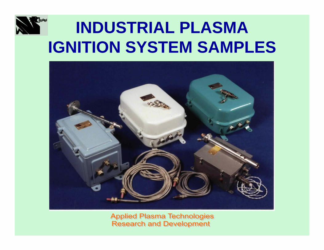
INDUSTRIAL PLASMA IGNITION SYSTEM SAMPLES

INDUSTRIAL AND MARINE PLASMA IGNITION SYSTEM
Over 1200 systems are installed and operating all over the world
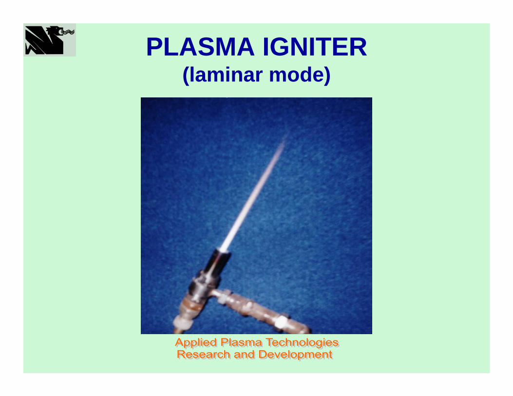
PLASMA IGNITER(laminar mode)
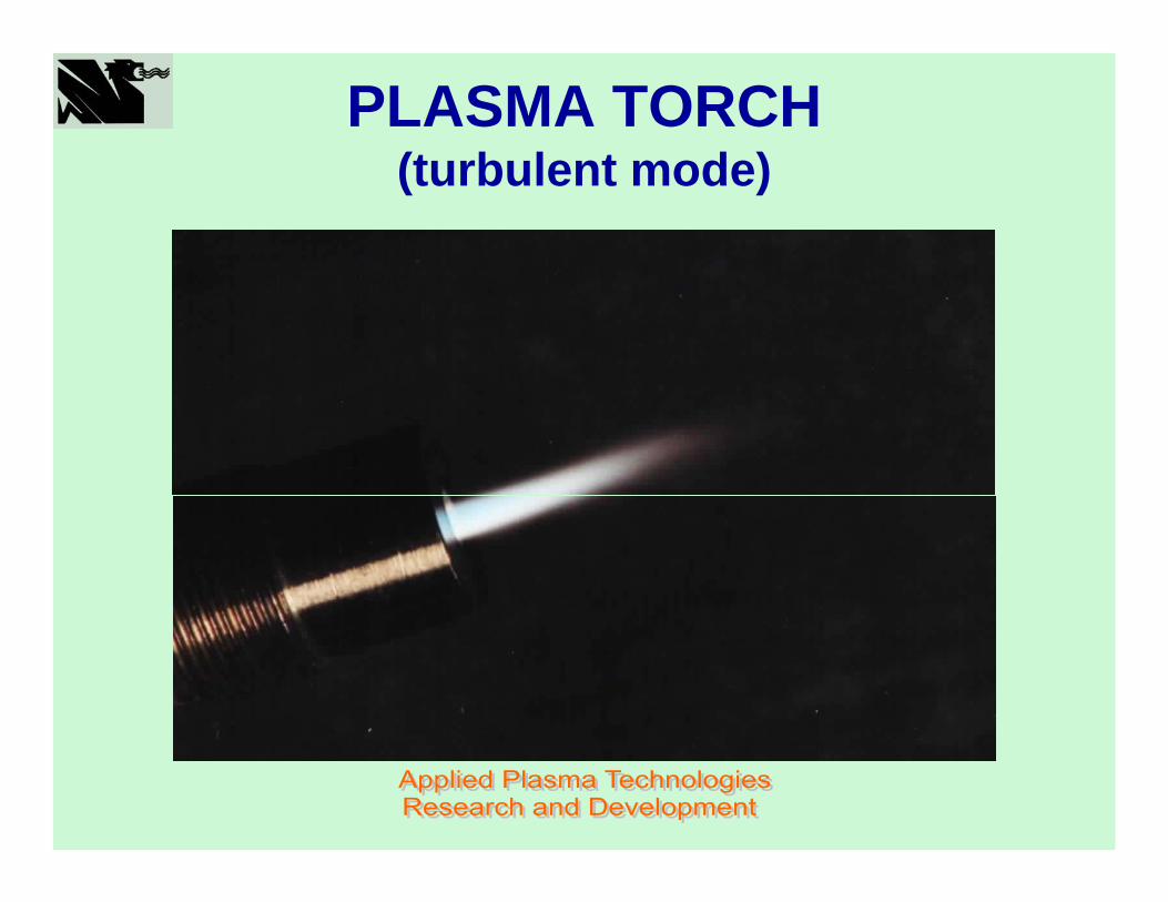
PLASMA TORCH(turbulent mode)
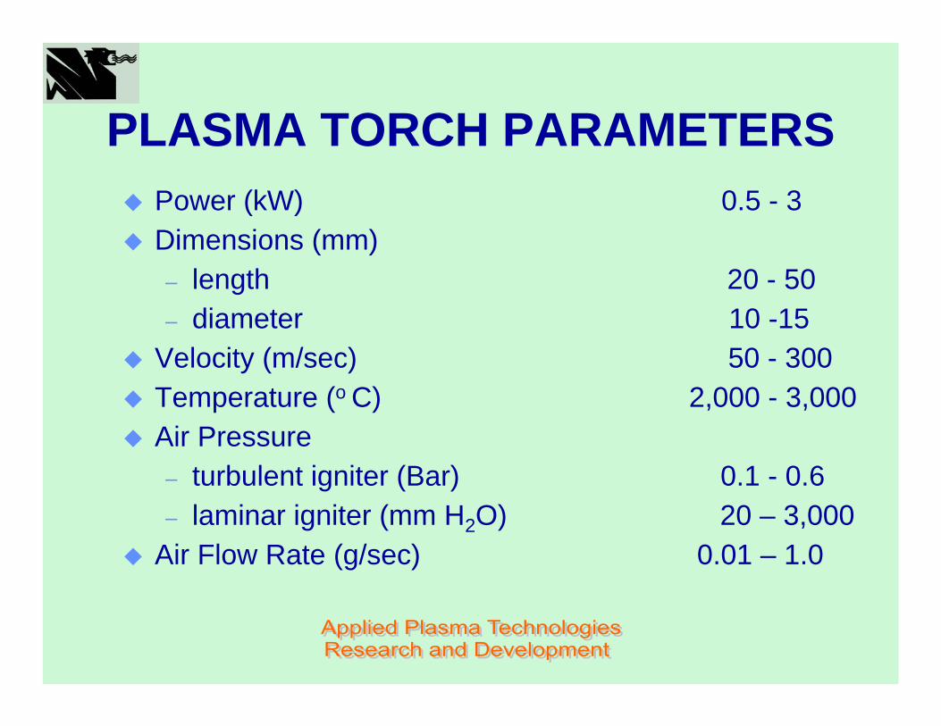
PLASMA TORCH PARAMETERSPower (kW) 0.5 - 3Dimensions (mm)– length 20 - 50– diameter 10 -15
Velocity (m/sec) 50 - 300Temperature (o C) 2,000 - 3,000Air Pressure– turbulent igniter (Bar) 0.1 - 0.6– laminar igniter (mm H2O) 20 – 3,000
Air Flow Rate (g/sec) 0.01 – 1.0
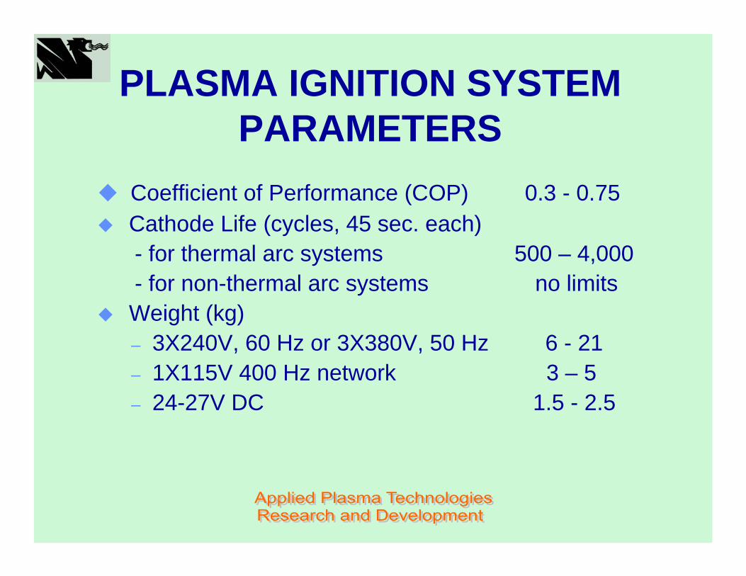
PLASMA IGNITION SYSTEM PARAMETERS
Coefficient of Performance (COP) 0.3 - 0.75Cathode Life (cycles, 45 sec. each) - for thermal arc systems 500 – 4,000- for non-thermal arc systems no limitsWeight (kg)– 3X240V, 60 Hz or 3X380V, 50 Hz 6 - 21– 1X115V 400 Hz network 3 – 5– 24-27V DC 1.5 - 2.5
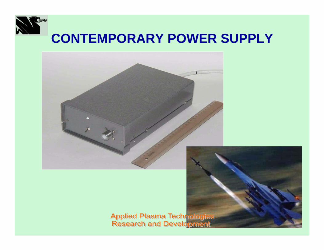
CONTEMPORARY POWER SUPPLY

PLASMA STABILIZATION SYSTEMSPLASMA FUEL NOZZLE

PLASMA NATURAL GAS NOZZLE
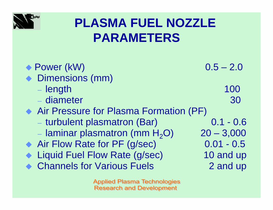
PLASMA FUEL NOZZLE PARAMETERS
Power (kW) 0.5 – 2.0Dimensions (mm)– length 100– diameter 30Air Pressure for Plasma Formation (PF)– turbulent plasmatron (Bar) 0.1 - 0.6– laminar plasmatron (mm H2O) 20 – 3,000Air Flow Rate for PF (g/sec) 0.01 - 0.5Liquid Fuel Flow Rate (g/sec) 10 and upChannels for Various Fuels 2 and up
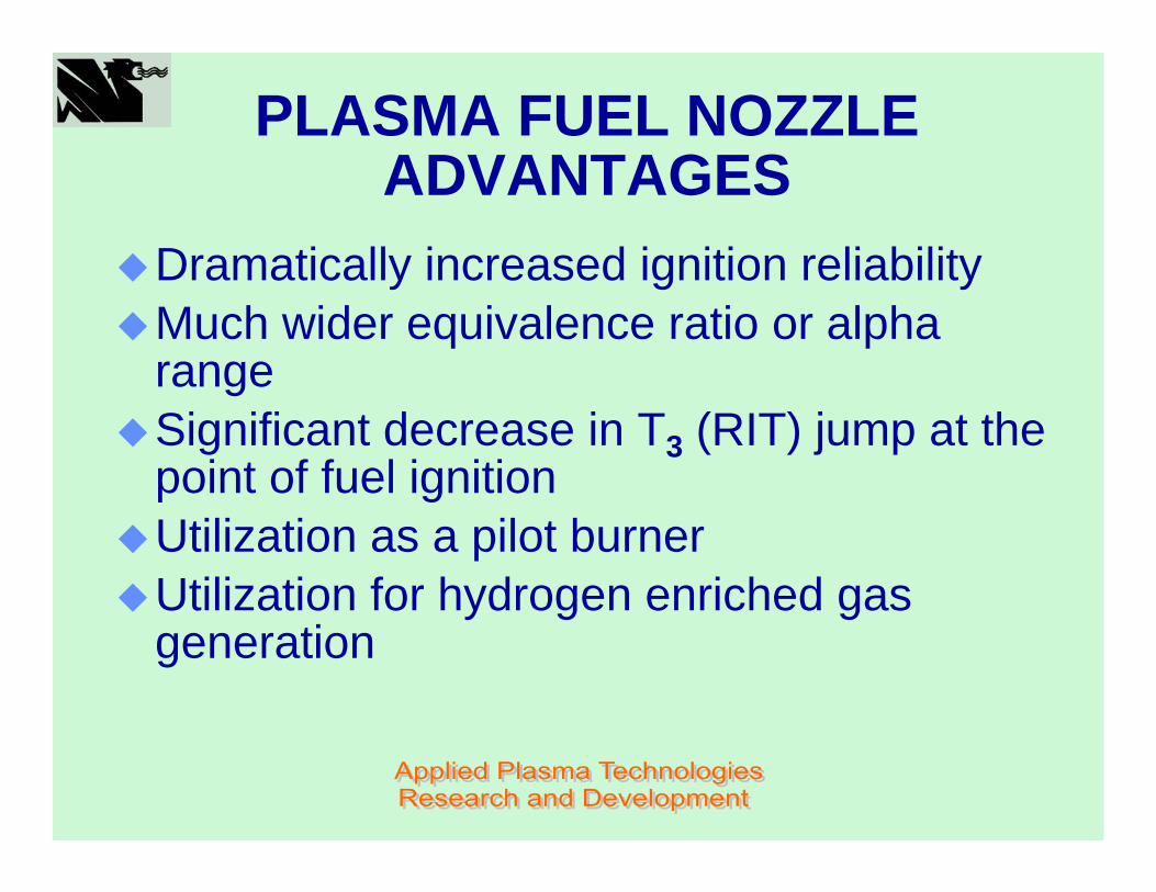
PLASMA FUEL NOZZLE ADVANTAGES
Dramatically increased ignition reliabilityMuch wider equivalence ratio or alpha rangeSignificant decrease in T3 (RIT) jump at the point of fuel ignitionUtilization as a pilot burnerUtilization for hydrogen enriched gas generation

PLASMA FUEL NOZZLE ADVANTAGES (cont)
Reduction of a combustion zone geometryReduction of the combustion chamber walls temperatureIncrease of a combustion efficiency (COP)Achieving smokeless operation Simultaneous burning of several fuelsSmooth regulation in a wider turn down ratio
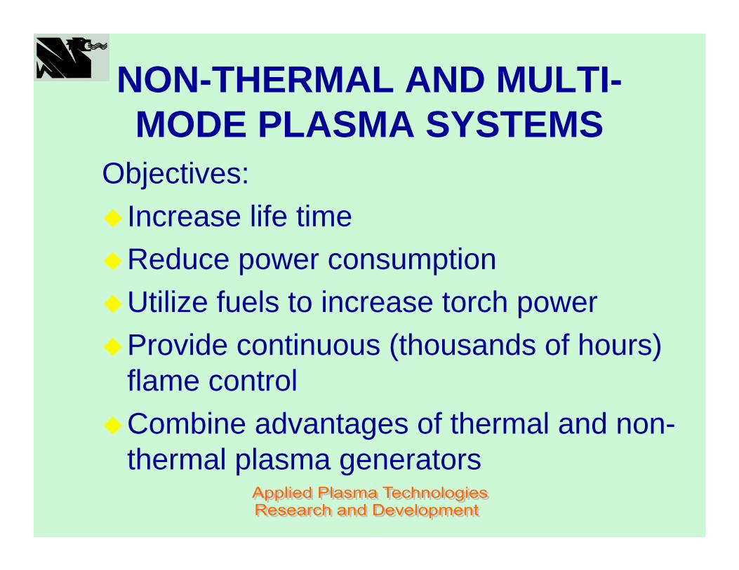
NON-THERMAL AND MULTI-MODE PLASMA SYSTEMS
Objectives:Increase life timeReduce power consumptionUtilize fuels to increase torch powerProvide continuous (thousands of hours) flame controlCombine advantages of thermal and non-thermal plasma generators

2020
OPERATION PRINCIPLESOF THE PLASMA PILOT
Pressure sensor
PowerSupply
I = f (P2)
Air

2121
PRESSURE DIFFERENTIAL ON THE COMBUSTOR WALL DEPENDING ON
THE TURBINE OPERATION MODE
15 100 100
6000
0
2000
4000
6000
8000
1 2 3 4Operation mode
Pres
sure
diff
eren
tial,
mm
of H
2O
1 - 2 – Ignition, ∆ P = 15 – 100 mm H2O, τ = 3 – 5 min2 – 3 – Yield (heating), ∆ P = const, τ = 10 – 15 min3 – 4 – Load, ∆ P = 100 – 6,000 mm H2O, τ = 3 min – ∞
2222
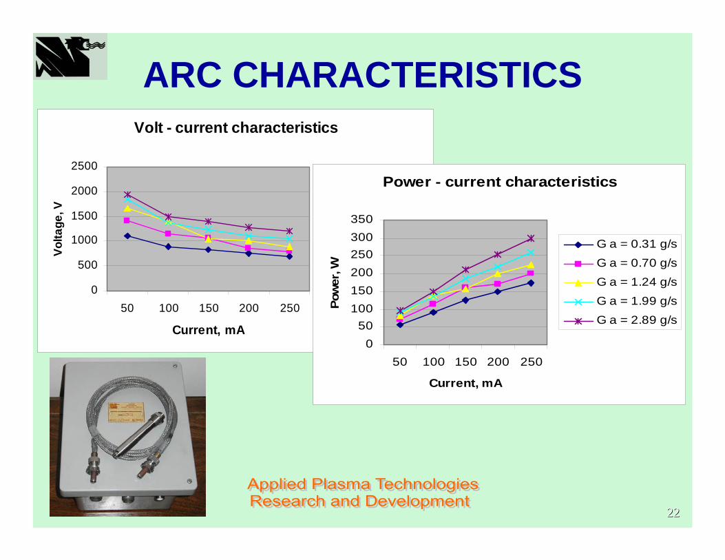
ARC CHARACTERISTICSVolt - current characteristics
0
500
1000
1500
2000
2500
50 100 150 200 250
Current, mA
Volta
ge, V
G a = 0.31 g/s
G a = 0.70 g/sG a = 1.24 g/s
G a = 1.99 g/s
G a = 2.89 g/s
Power - current characteristics
050
100150200250300350
50 100 150 200 250
Current, mA
Pow
er, W
G a = 0.31 g/s
G a = 0.70 g/s
G a = 1.24 g/s
G a = 1.99 g/s
G a = 2.89 g/s
2323
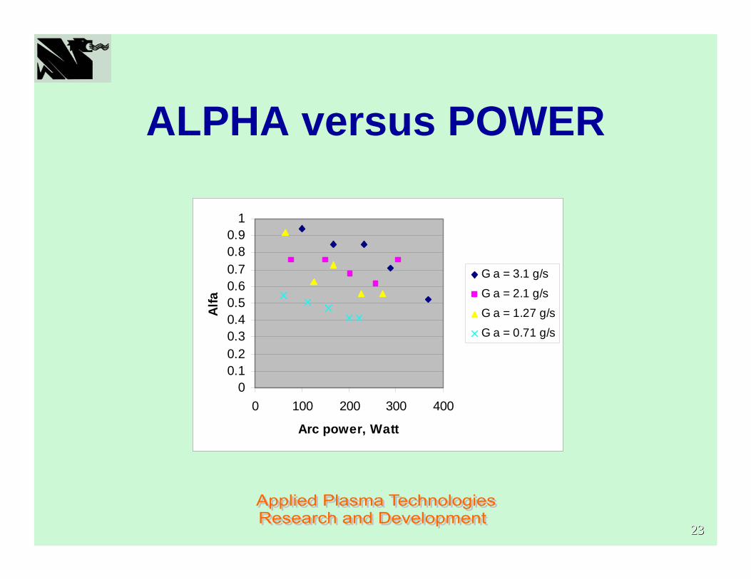
ALPHA versus POWER
00.10.20.30.40.50.60.70.80.9
1
0 100 200 300 400
Arc power, Watt
Alfa
G a = 3.1 g/s
G a = 2.1 g/s
G a = 1.27 g/s
G a = 0.71 g/s
2424
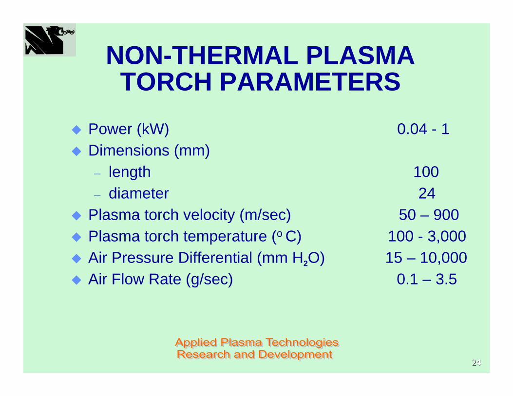
NON-THERMAL PLASMA TORCH PARAMETERS
Power (kW) 0.04 - 1Dimensions (mm)– length 100– diameter 24
Plasma torch velocity (m/sec) 50 – 900Plasma torch temperature (o C) 100 - 3,000Air Pressure Differential (mm H2O) 15 – 10,000Air Flow Rate (g/sec) 0.1 – 3.5
2525
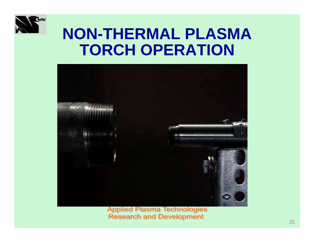
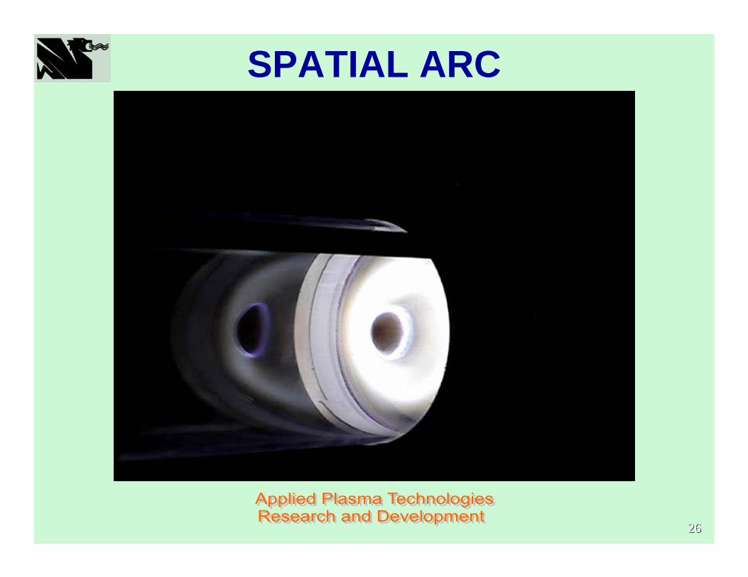
NON-THERMAL PLASMA TORCH OPERATION
2626
SPATIAL ARC
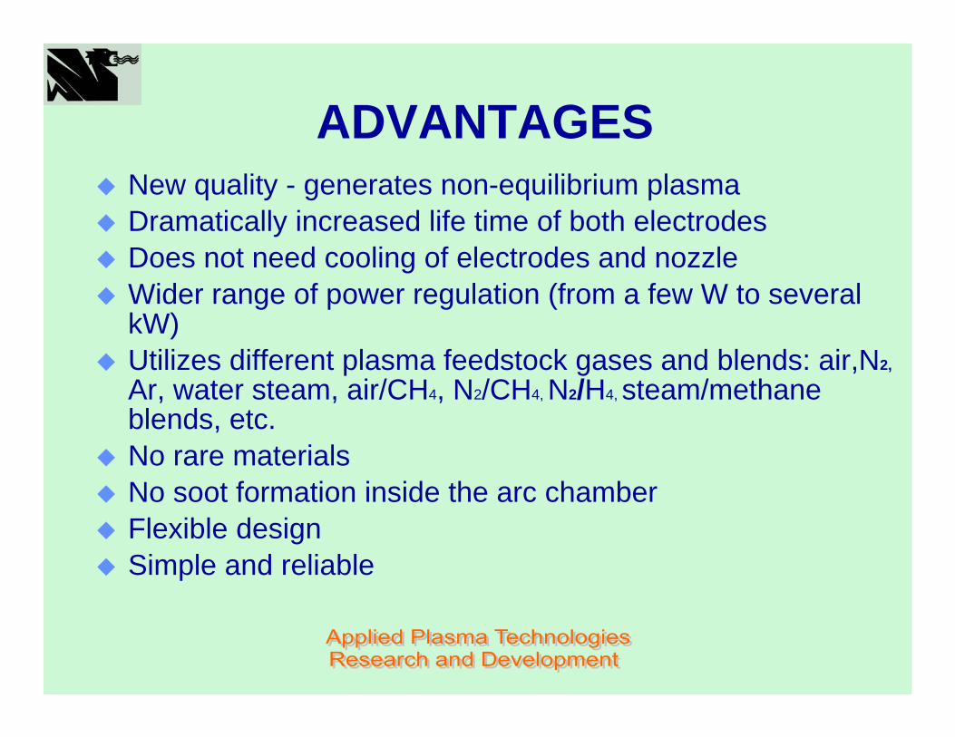
ADVANTAGES New quality - generates non-equilibrium plasmaDramatically increased life time of both electrodesDoes not need cooling of electrodes and nozzleWider range of power regulation (from a few W to several kW)Utilizes different plasma feedstock gases and blends: air,N2,
Ar, water steam, air/CH4, N2/CH4, N2/H4, steam/methane blends, etc.No rare materialsNo soot formation inside the arc chamberFlexible designSimple and reliable

MULTI-MODE PLASMA TORCHES

2929
NON-THERMAL PLASMA PILOT AND GAS IONIZER

PLASMA PILOT FOR AEROSPACE APPLICATION
3131
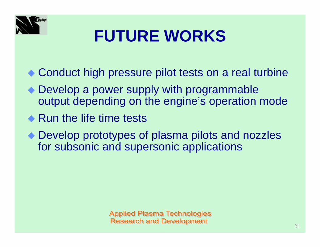
FUTURE WORKS
Conduct high pressure pilot tests on a real turbineDevelop a power supply with programmable output depending on the engine’s operation modeRun the life time testsDevelop prototypes of plasma pilots and nozzles for subsonic and supersonic applications
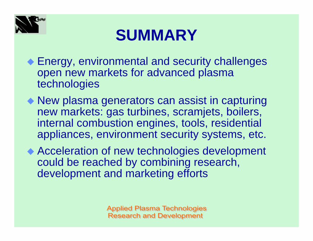
SUMMARYEnergy, environmental and security challenges open new markets for advanced plasma technologiesNew plasma generators can assist in capturing new markets: gas turbines, scramjets, boilers, internal combustion engines, tools, residential appliances, environment security systems, etc.Acceleration of new technologies development could be reached by combining research, development and marketing efforts
Related Documents


![[A PILOTS PERSPECTIVE OF THE 1989 PILOTS DISPUTE ]apaterson/aviation/1989_pilot_dispute.pdf · flight.org Alex Paterson | . [A PILOTS PERSPECTIVE OF THE 1989 PILOTS DISPUTE ] ALEX](https://static.cupdf.com/doc/110x72/5ad4c90f7f8b9aff228c436f/a-pilots-perspective-of-the-1989-pilots-dispute-apatersonaviation1989pilotdisputepdfflightorg.jpg)
![Detonators, Igniters, Primers, And Other Initiating Devices[1]](https://static.cupdf.com/doc/110x72/543cbed5b1af9fc02e8b4772/detonators-igniters-primers-and-other-initiating-devices1.jpg)