Multi Mission Re-Configurable UAV – Airfoil Shape Parameterisation Study 22 nd International Unmanned Air Vehicle Systems Conference – 16-18 April 2007 MULTI MISSION RE-CONFIGURABLE UAV – AIRFOIL SHAPE PARAMETERISATION STUDY Manas S. Khurana # , Arvind K. Sinha, Hadi Winarto The Sir Lawrence Wackett Centre for Aerospace Design Technology RMIT University, GPO Box 2476v, Melbourne, Victoria 3001, Australia Tel: +61 3 9645 4530 Fax: +61 3 9645 4534 # Email: [email protected] Abstract The paper outlines the methodology of shape parameterisation techniques to generate airfoils for design and optimisation. The aim of this investigation is to examine the flexibility of two analytical shape functions; the Hicks-Henne and Wagner Polynomials for airfoil shape parameterisation. A symmetrical base airfoil is used as the starting point and an optimiser is used to duplicate three distinct target sections as designed specifically for slow speed long endurance roles; a foreseen operational scenario for a Multi- Mission UAV. The fitness function though a linear gradient search algorithm is formulated based on an objective function of minimising the difference between base and target geometries is evaluated through a high fidelity flow solver. The results indicate that the Hicks-Henne approximation is superior to Wagner polynomials in duplicating the target airfoils; as observed through a lower fitness measurement, higher computational efficiency and in the convergence of aerodynamic coefficients in comparison to actual airfoil data. Biography Manas holds a Bachelor of Engineering Degree in Aerospace with Honours and also a Graduate Certificate in Engineering Management. He is currently undertaking a PhD program in computational and applied aerodynamic design of morphing wings. In addition to his candidature, Manas is also a Research Assistant at the Wackett Aerospace Centre. Arvind K. Sinha has a service record of 31 years, which includes Defence forces, industry and academic institutions. He has several qualifications, scholarships, awards, industrial research projects, research papers and public presentations to credit. He is presently the Director of The Sir Lawrence Wackett Centre for Aerospace Design Technology, Royal Melbourne Institute of Technology, Melbourne, Australia. Hadi Winarto is an Associate Professor at the School of Aerospace, Mechanical and Manufacturing Engineering. His research areas include applied and computational aerodynamic design with emphasis on software development, analysis of turbulent flows and thermo-fluid dynamics. Hadi further supervises students on their research at the Wackett Aerospace Centre.

Welcome message from author
This document is posted to help you gain knowledge. Please leave a comment to let me know what you think about it! Share it to your friends and learn new things together.
Transcript
Multi Mission Re-Configurable UAV – Airfoil Shape Parameterisation Study
22nd
International Unmanned Air Vehicle Systems Conference – 16-18 April 2007
MULTI MISSION RE-CONFIGURABLE UAV – AIRFOIL SHAPE
PARAMETERISATION STUDY
Manas S. Khurana
#, Arvind K. Sinha, Hadi Winarto
The Sir Lawrence Wackett Centre for Aerospace Design Technology
RMIT University, GPO Box 2476v, Melbourne, Victoria 3001, Australia
Tel: +61 3 9645 4530 Fax: +61 3 9645 4534 #Email: [email protected]
Abstract
The paper outlines the methodology of shape parameterisation techniques to generate airfoils for design
and optimisation. The aim of this investigation is to examine the flexibility of two analytical shape
functions; the Hicks-Henne and Wagner Polynomials for airfoil shape parameterisation. A symmetrical
base airfoil is used as the starting point and an optimiser is used to duplicate three distinct target sections
as designed specifically for slow speed long endurance roles; a foreseen operational scenario for a Multi-
Mission UAV. The fitness function though a linear gradient search algorithm is formulated based on an
objective function of minimising the difference between base and target geometries is evaluated through a
high fidelity flow solver. The results indicate that the Hicks-Henne approximation is superior to Wagner
polynomials in duplicating the target airfoils; as observed through a lower fitness measurement, higher
computational efficiency and in the convergence of aerodynamic coefficients in comparison to actual
airfoil data.
Biography
Manas holds a Bachelor of Engineering Degree in Aerospace with Honours and also a Graduate Certificate
in Engineering Management. He is currently undertaking a PhD program in computational and applied
aerodynamic design of morphing wings. In addition to his candidature, Manas is also a Research Assistant
at the Wackett Aerospace Centre.
Arvind K. Sinha has a service record of 31 years, which includes Defence forces, industry and academic
institutions. He has several qualifications, scholarships, awards, industrial research projects, research
papers and public presentations to credit. He is presently the Director of The Sir Lawrence Wackett Centre
for Aerospace Design Technology, Royal Melbourne Institute of Technology, Melbourne, Australia.
Hadi Winarto is an Associate Professor at the School of Aerospace, Mechanical and Manufacturing Engineering. His research areas include applied and computational aerodynamic design with emphasis on software development, analysis of turbulent flows and thermo-fluid dynamics. Hadi further supervises students on their research at the Wackett Aerospace Centre.
Multi Mission Re-Configurable UAV – Airfoil Shape Parameterisation Study
22nd
International Unmanned Air Vehicle Systems Conference – 16-18 April 2007
Nomenclature
iia β, = Hicks-Henne Peak
ƒapprox. = Approximated Airfoil
λi = Design Variables
ƒi(x) = Shape Functions
(L/D)max = Maximum Lift-to-Drag
ƒtarget = Target Airfoil
(x/c)i = Chordwise Position
ak = Scalar Step Length
CL = Coefficient of Lift
Configurable-Unmanned
Aerial Vehicle
CP = Coefficient of Pressure
Location Values
MM-RC-UAV = Multi-Mission- Re-
pk = Search Direction
Ratio
Re = Reynolds Number
t/c = Thickness-to-Chord Ratio
xk = Current Iteration
∆ƒ = Fitness Function
∆ƒmin = Objective Function
Introduction
Traditional concepts of developing platforms for
uni-mission requirements has led to a large fleet
of UAVs with inherent ‘issues and challenges’ of
operation and support [1]. A multi-mission
platform is needed to address the issues and
challenges. Development of pioneering design
aircraft concepts providing multi-role and multi-
mission capabilities has been acknowledged by
renowned operators and designers and is cost and
mission effective. Hence, the need to introduce
aerial platforms that addresses a wide client base
by encompassing civil and military mission
capabilities in a single platform require further
investigations.
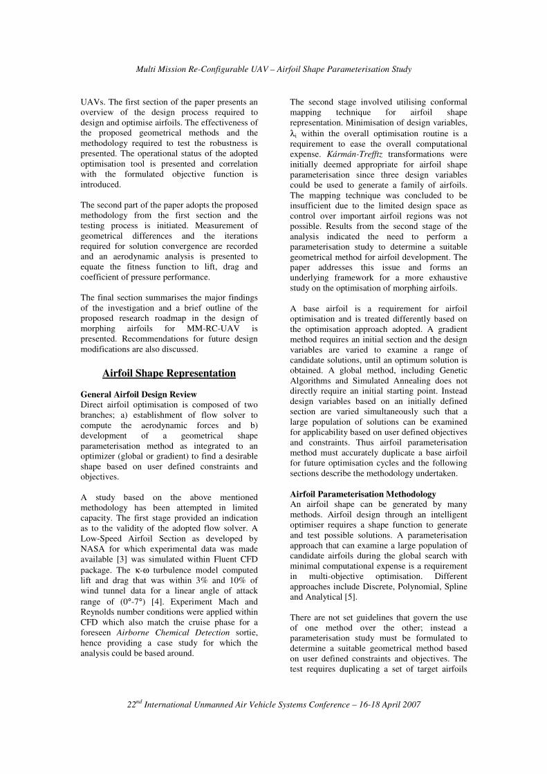
A detail market survey on Australian mission
requirement provided an operational and design
window for the development of UAV with multi-
mission capabilities [2]. Researchers at the Sir
Lawrence Wackett Centre for Aerospace
Technology have examined the prospect of
developing a Re-Configurable Multi-Mission
Unmanned Aerial Vehicle (MM-RC-UAV)
design concept for the identified class of UAVs (
Table 1). The concept proposes flexibility of
multiple payload configurations. Initial
investigations of platform concepts examined the
prospect of introducing wing and fuselage
extensions to address the disparate requirements
of payload and flight performance. The optimal
operational requirements though achievable, it is
a major design and manufacturing challenge.
Table 1: Australian UAV Market Survey
Technology
Classification
Missions
Support UAV
� High-Altitude Long Endurance
(HALE);
� High-Altitude Long Operation
(HALO); and
� Medium Altitude Medium
Endurance (MAME)
Combat UAV
� Unmanned Combat Aerial
Vehicle (UCAV-HL) – High
Altitude Long Endurance;
� Unmanned Combat Aerial
Vehicle (UCAV-MM) – Medium
Altitude Medium Endurance;
The mission requirements cover long endurance
sorties at medium altitudes over large distances.
This results in high fuel requirements and fuel
storage in wings will result in thick airfoil
sections. The reconnaissance and surveillance
component of the mission is at low speeds.
Excessive viscous affects are prominent at low
Mach and Reynolds number. Thus a constrained
optimisation model to maximise the glide ratio to
overcome the high drag properties associated
with low speed operations is needed in the
design. Traditional uni-mission UAVs have
limited performance capability and operations
outside the intended design spectrum lead to sub-
optimal flight performance. A revolutionary
design concept to address this limitation is
foreseen for future operations.
Wing extensions as proposed earlier, was
considered in the form of morphing wings to
address the requirements of long endurance.
Morphing wings will enhance the operational
performance with inbuilt flexibility of wing
shape to achieve the desired aerodynamic
performance. Development of an intelligent
airfoil optimisation model is needed to provide
the framework for a more detail wing design.
Design of unique airfoils that are best suited for
each flight segment of the mission profile is to
be established. In this paper a geometrical
methodology for the development of an airfoil
optimisation model is presented.
The research is part of an overall effort of
developing morphing airfoils for MM-RC-
Multi Mission Re-Configurable UAV – Airfoil Shape Parameterisation Study
22nd
International Unmanned Air Vehicle Systems Conference – 16-18 April 2007
UAVs. The first section of the paper presents an
overview of the design process required to
design and optimise airfoils. The effectiveness of
the proposed geometrical methods and the
methodology required to test the robustness is
presented. The operational status of the adopted
optimisation tool is presented and correlation
with the formulated objective function is
introduced.
The second part of the paper adopts the proposed
methodology from the first section and the
testing process is initiated. Measurement of
geometrical differences and the iterations
required for solution convergence are recorded
and an aerodynamic analysis is presented to
equate the fitness function to lift, drag and
coefficient of pressure performance.
The final section summarises the major findings
of the investigation and a brief outline of the
proposed research roadmap in the design of
morphing airfoils for MM-RC-UAV is
presented. Recommendations for future design
modifications are also discussed.
Airfoil Shape Representation
General Airfoil Design Review Direct airfoil optimisation is composed of two
branches; a) establishment of flow solver to
compute the aerodynamic forces and b)
development of a geometrical shape
parameterisation method as integrated to an
optimizer (global or gradient) to find a desirable
shape based on user defined constraints and
objectives.
A study based on the above mentioned
methodology has been attempted in limited
capacity. The first stage provided an indication
as to the validity of the adopted flow solver. A
Low-Speed Airfoil Section as developed by
NASA for which experimental data was made
available [3] was simulated within Fluent CFD
package. The κ-ω turbulence model computed
lift and drag that was within 3% and 10% of
wind tunnel data for a linear angle of attack
range of (0°-7°) [4]. Experiment Mach and
Reynolds number conditions were applied within
CFD which also match the cruise phase for a
foreseen Airborne Chemical Detection sortie,
hence providing a case study for which the
analysis could be based around.
The second stage involved utilising conformal
mapping technique for airfoil shape
representation. Minimisation of design variables,
λi within the overall optimisation routine is a
requirement to ease the overall computational
expense. Kármán-Trefftz transformations were
initially deemed appropriate for airfoil shape
parameterisation since three design variables
could be used to generate a family of airfoils.
The mapping technique was concluded to be
insufficient due to the limited design space as
control over important airfoil regions was not
possible. Results from the second stage of the
analysis indicated the need to perform a
parameterisation study to determine a suitable
geometrical method for airfoil development. The
paper addresses this issue and forms an
underlying framework for a more exhaustive
study on the optimisation of morphing airfoils.
A base airfoil is a requirement for airfoil
optimisation and is treated differently based on
the optimisation approach adopted. A gradient
method requires an initial section and the design
variables are varied to examine a range of
candidate solutions, until an optimum solution is
obtained. A global method, including Genetic
Algorithms and Simulated Annealing does not
directly require an initial starting point. Instead
design variables based on an initially defined
section are varied simultaneously such that a
large population of solutions can be examined
for applicability based on user defined objectives
and constraints. Thus airfoil parameterisation
method must accurately duplicate a base airfoil
for future optimisation cycles and the following
sections describe the methodology undertaken.
Airfoil Parameterisation Methodology An airfoil shape can be generated by many
methods. Airfoil design through an intelligent
optimiser requires a shape function to generate
and test possible solutions. A parameterisation
approach that can examine a large population of
candidate airfoils during the global search with
minimal computational expense is a requirement
in multi-objective optimisation. Different
approaches include Discrete, Polynomial, Spline
and Analytical [5].
There are not set guidelines that govern the use
of one method over the other; instead a
parameterisation study must be formulated to
determine a suitable geometrical method based
on user defined constraints and objectives. The
test requires duplicating a set of target airfoils
Multi Mission Re-Configurable UAV – Airfoil Shape Parameterisation Study
22nd
International Unmanned Air Vehicle Systems Conference – 16-18 April 2007
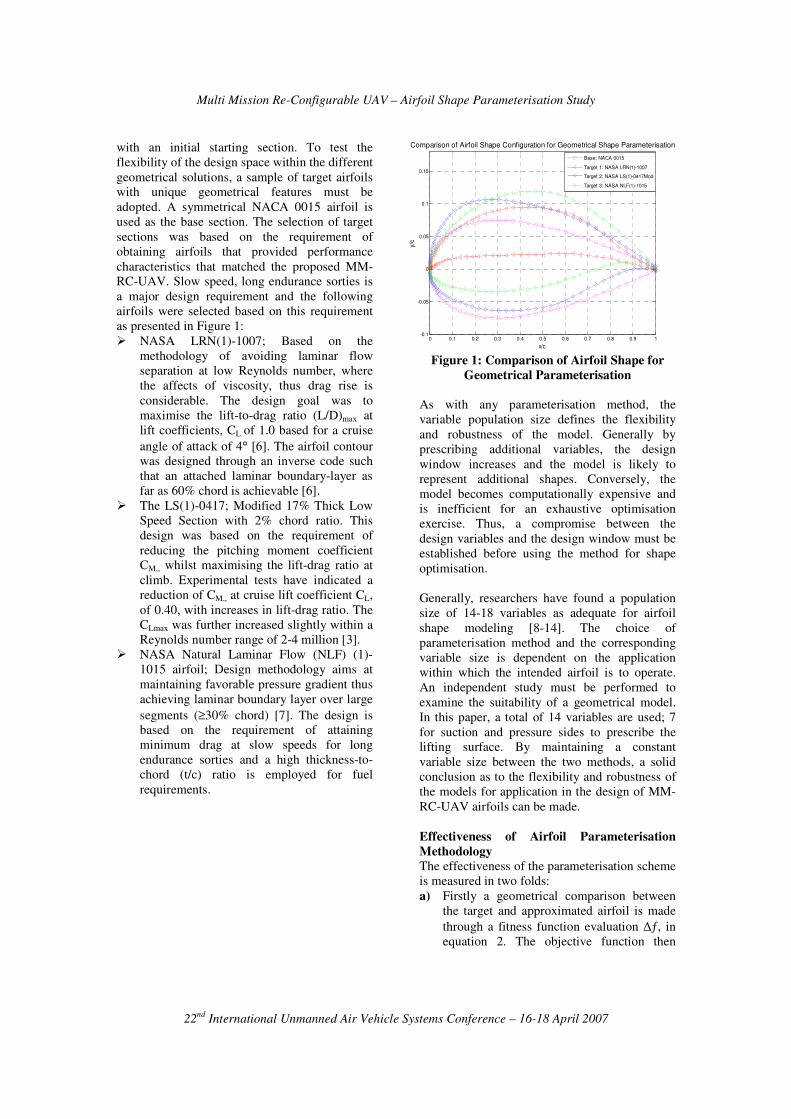
with an initial starting section. To test the
flexibility of the design space within the different
geometrical solutions, a sample of target airfoils
with unique geometrical features must be
adopted. A symmetrical NACA 0015 airfoil is
used as the base section. The selection of target
sections was based on the requirement of
obtaining airfoils that provided performance
characteristics that matched the proposed MM-
RC-UAV. Slow speed, long endurance sorties is
a major design requirement and the following
airfoils were selected based on this requirement
as presented in Figure 1:
� NASA LRN(1)-1007; Based on the
methodology of avoiding laminar flow
separation at low Reynolds number, where
the affects of viscosity, thus drag rise is
considerable. The design goal was to
maximise the lift-to-drag ratio (L/D)max at
lift coefficients, CL of 1.0 based for a cruise
angle of attack of 4° [6]. The airfoil contour
was designed through an inverse code such
that an attached laminar boundary-layer as
far as 60% chord is achievable [6].
� The LS(1)-0417; Modified 17% Thick Low
Speed Section with 2% chord ratio. This
design was based on the requirement of
reducing the pitching moment coefficient
CM,, whilst maximising the lift-drag ratio at
climb. Experimental tests have indicated a
reduction of CM,, at cruise lift coefficient CL,
of 0.40, with increases in lift-drag ratio. The
CLmax was further increased slightly within a
Reynolds number range of 2-4 million [3].
� NASA Natural Laminar Flow (NLF) (1)-
1015 airfoil; Design methodology aims at
maintaining favorable pressure gradient thus
achieving laminar boundary layer over large
segments (≥30% chord) [7]. The design is
based on the requirement of attaining
minimum drag at slow speeds for long
endurance sorties and a high thickness-to-
chord (t/c) ratio is employed for fuel
requirements.
0 0.1 0.2 0.3 0.4 0.5 0.6 0.7 0.8 0.9 1-0.1
-0.05
0
0.05
0.1
0.15
Comparison of Airfoil Shape Configuration for Geometrical Shape Parameterisation
x/c
y/c
Base: NACA 0015
Target 1: NASA LRN(1)-1007
Target 2: NASA LS(1)-0417Mod
Target 3: NASA NLF(1)-1015
Figure 1: Comparison of Airfoil Shape for
Geometrical Parameterisation
As with any parameterisation method, the
variable population size defines the flexibility
and robustness of the model. Generally by
prescribing additional variables, the design
window increases and the model is likely to
represent additional shapes. Conversely, the
model becomes computationally expensive and
is inefficient for an exhaustive optimisation
exercise. Thus, a compromise between the
design variables and the design window must be
established before using the method for shape
optimisation.
Generally, researchers have found a population
size of 14-18 variables as adequate for airfoil
shape modeling [8-14]. The choice of
parameterisation method and the corresponding
variable size is dependent on the application
within which the intended airfoil is to operate.
An independent study must be performed to
examine the suitability of a geometrical model.
In this paper, a total of 14 variables are used; 7
for suction and pressure sides to prescribe the
lifting surface. By maintaining a constant
variable size between the two methods, a solid
conclusion as to the flexibility and robustness of
the models for application in the design of MM-
RC-UAV airfoils can be made.
Effectiveness of Airfoil Parameterisation
Methodology
The effectiveness of the parameterisation scheme
is measured in two folds:
a) Firstly a geometrical comparison between
the target and approximated airfoil is made
through a fitness function evaluation ∆ƒ, in
equation 2. The objective function then
Multi Mission Re-Configurable UAV – Airfoil Shape Parameterisation Study
22nd
International Unmanned Air Vehicle Systems Conference – 16-18 April 2007
becomes minimisation of ∆ƒmin between the
two geometrical sets.
Position Chordwise)/(
and Airfoil; edApproximat
Airfoil;Target
:
))/()/((
approx.
target
.arg
=
=
=
−∑=∆
i
iapproxiett
cx
f
f
where
cxfcxfabsf
(Eqn 1)
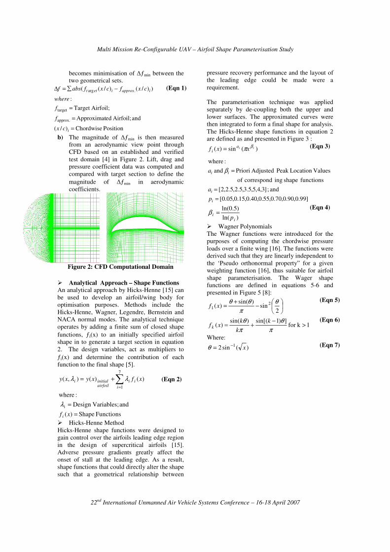
b) The magnitude of ∆ƒmin is then measured
from an aerodynamic view point through
CFD based on an established and verified
test domain [4] in Figure 2. Lift, drag and
pressure coefficient data was computed and
compared with target section to define the
magnitude of ∆ƒmin in aerodynamic
coefficients.
Figure 2: CFD Computational Domain
� Analytical Approach – Shape Functions
An analytical approach by Hicks-Henne [15] can
be used to develop an airfoil/wing body for
optimisation purposes. Methods include the
Hicks-Henne, Wagner, Legendre, Bernstein and
NACA normal modes. The analytical technique
operates by adding a finite sum of closed shape
functions, ƒi(x) to an initially specified airfoil
shape in to generate a target section in equation
2. The design variables, act as multipliers to
ƒi(x) and determine the contribution of each
function to the final shape [5].
∑=
+=7
1
)()(),(
i
iiairfoilinitiali xfxyxy λλ
Functions Shape)(
and Variables;Design
:where
i
=
=
xf i
λ
(Eqn 2)
� Hicks-Henne Method
Hicks-Henne shape functions were designed to
gain control over the airfoils leading edge region
in the design of supercritical airfoils [15].
Adverse pressure gradients greatly affect the
onset of stall at the leading edge. As a result,
shape functions that could directly alter the shape
such that a geometrical relationship between
pressure recovery performance and the layout of
the leading edge could be made were a
requirement.
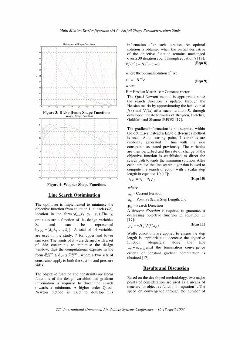
The parameterisation technique was applied
separately by de-coupling both the upper and
lower surfaces. The approximated curves were
then integrated to form a final shape for analysis.
The Hicks-Henne shape functions in equation 2
are defined as and presented in Figure 3 :
)(sin)( ii xxfa
iβπ= (Eqn 3)
]99.0,90.0,70.0,55.0,40.0,15.0,05.0[
and ; ]3,4,5,5.3,5.2,5.2,2[
functions shape ing correspond of
ValuesLocation Peak Adjusted Priori and
:where
=
=
=
i
i
ii
p
a
a β
)ln(
)5.0ln(
i
ip
=β (Eqn 4)
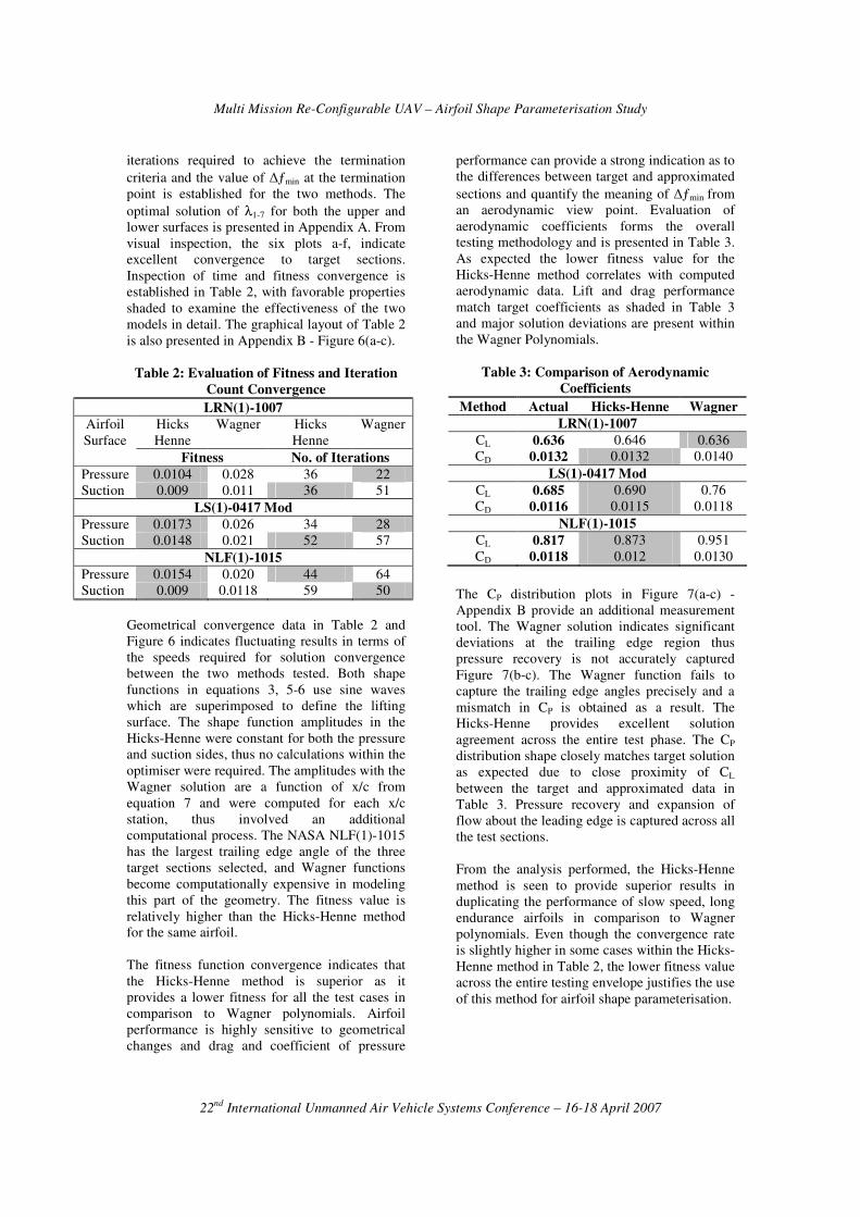
� Wagner Polynomials
The Wagner functions were introduced for the
purposes of computing the chordwise pressure
loads over a finite wing [16]. The functions were
derived such that they are linearly independent to
the ‘Pseudo orthonormal property” for a given
weighting function [16], thus suitable for airfoil
shape parameterisation. The Wager shape
functions are defined in equations 5-6 and
presented in Figure 5 [8]:
−
+=
2sin
)sin()(
21
θ
π
θθxf
(Eqn 5)
1kfor ])1sin[()sin(
)( >−
+=π
θ
π
θ k
k
kxf k
(Eqn 6)
Where:
)(sin2 1 x−=θ
(Eqn 7)
Multi Mission Re-Configurable UAV – Airfoil Shape Parameterisation Study
22nd
International Unmanned Air Vehicle Systems Conference – 16-18 April 2007
0 0.1 0.2 0.3 0.4 0.5 0.6 0.7 0.8 0.9 10
0.1
0.2
0.3
0.4
0.5
0.6
0.7
0.8
0.9
1
Hicks-Henne Shape Functions
x
y
Figure 3: Hicks-Henne Shape Functions
0 0.1 0.2 0.3 0.4 0.5 0.6 0.7 0.8 0.9 1-0.4
-0.3
-0.2
-0.1
0
0.1
0.2
0.3
0.4
0.5
Wagner Shape Functions
x
y
Figure 4: Wagner Shape Functions
Line Search Optimisation
The optimiser is implemented to minimise the
objective function from equation 1, at each (x/c)i
location in the form ).(y ,,21,min nyyf…
∆ The yi
ordinates are a function of the design variables
λi, and can be represented
by ].,,[ 72,1 λλλ …=iy A total of 14 variables
are used in the study; 7 for upper and lower
surfaces. The limits of λ1-7 are defined with a set
of side constraints to minimise the design
window, thus the computational expense in the
form UpperLower717171 −−− ≤≤ λλλ , where a two sets of
constraints apply to both the suction and pressure
sides.
The objective function and constraints are linear
functions of the design variables and gradient
information is required to direct the search
towards a minimum. A higher order Quasi-
Newton method is used to develop this
information after each iteration. An optimal
solution is obtained when the partial derivative
of the objective function remains unchanged
over a 30 iteration count through equation 8 [17].
0)( ** ≈+=∇ cHxxf (Eqn 8)
ectorConstant v c ;Matrix Hessian H
where;
x
:is solution x optimal thewhere
1*
*
==
−= −cH
(Eqn 9)
The Quasi-Newton method is appropriate since
the search direction is updated through the
Hessian matrix by approximating the behavior of
ƒ(x) and ∇ƒ(x) after each iteration K, through
developed update formulas of Broyden, Fletcher,
Goldfarb and Shanno (BFGS) [17].
The gradient information is not supplied within
the optimiser instead a finite differences method
is used. As a starting point, 7 variables are
randomly generated in line with the side
constraints as stated previously. The variables
are then perturbed and the rate of change of the
objective function is established to direct the
search path towards the minimum solution. After
each iteration the line search algorithm is used to
compute the search direction with a scalar step
length in equation 10 [17]:
kkkk paxx +=+1 (Eqn 10)
DirectionSearch p
and Length; StepScalar Positivea
Iteration;Current
k
k
=
=
=kx
where
A descent direction is required to guarantee a
decreasing objective function in equation 11
[17]:
)(.1
kkk xfHp ∇−= − (Eqn 11)
Wolfe conditions are applied to ensure the step
length is appropriate to decrease the objective
function adequately along the line
,kkk pax + until the termination convergence
criteria of constant gradient computation is
obtained [17].
Results and Discussion
Based on the developed methodology, two major
points of consideration are used as a means of
measure for objective function in equation 1. The
speed on convergence through the number of
Multi Mission Re-Configurable UAV – Airfoil Shape Parameterisation Study
22nd
International Unmanned Air Vehicle Systems Conference – 16-18 April 2007
iterations required to achieve the termination
criteria and the value of ∆ƒmin at the termination
point is established for the two methods. The
optimal solution of λ1-7 for both the upper and
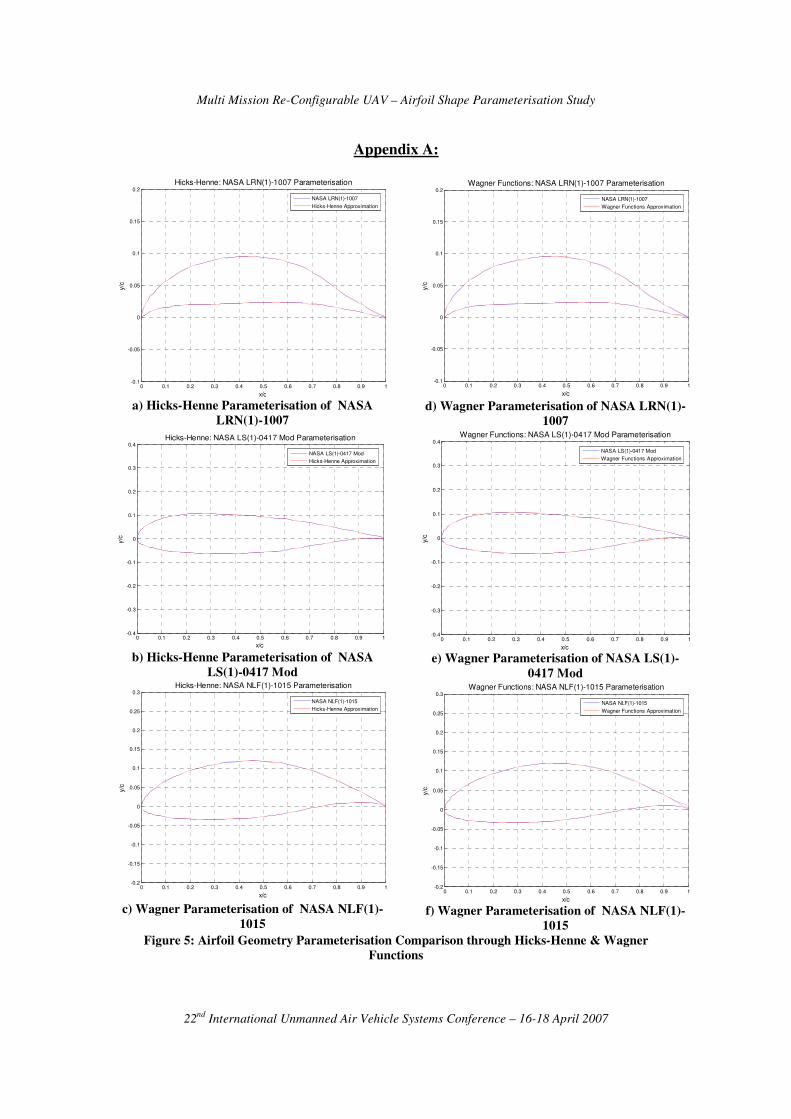
lower surfaces is presented in Appendix A. From
visual inspection, the six plots a-f, indicate
excellent convergence to target sections.
Inspection of time and fitness convergence is
established in Table 2, with favorable properties
shaded to examine the effectiveness of the two
models in detail. The graphical layout of Table 2
is also presented in Appendix B - Figure 6(a-c).
Table 2: Evaluation of Fitness and Iteration
Count Convergence
LRN(1)-1007
Hicks
Henne
Wagner Hicks
Henne
Wagner Airfoil
Surface
Fitness No. of Iterations
Pressure 0.0104 0.028 36 22
Suction 0.009 0.011 36 51
LS(1)-0417 Mod
Pressure 0.0173 0.026 34 28
Suction 0.0148 0.021 52 57
NLF(1)-1015
Pressure 0.0154 0.020 44 64
Suction 0.009 0.0118 59 50
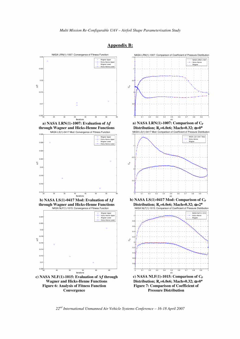
Geometrical convergence data in Table 2 and
Figure 6 indicates fluctuating results in terms of
the speeds required for solution convergence
between the two methods tested. Both shape
functions in equations 3, 5-6 use sine waves
which are superimposed to define the lifting
surface. The shape function amplitudes in the
Hicks-Henne were constant for both the pressure
and suction sides, thus no calculations within the
optimiser were required. The amplitudes with the
Wagner solution are a function of x/c from
equation 7 and were computed for each x/c
station, thus involved an additional
computational process. The NASA NLF(1)-1015
has the largest trailing edge angle of the three
target sections selected, and Wagner functions
become computationally expensive in modeling
this part of the geometry. The fitness value is
relatively higher than the Hicks-Henne method
for the same airfoil.
The fitness function convergence indicates that
the Hicks-Henne method is superior as it
provides a lower fitness for all the test cases in
comparison to Wagner polynomials. Airfoil
performance is highly sensitive to geometrical
changes and drag and coefficient of pressure
performance can provide a strong indication as to
the differences between target and approximated
sections and quantify the meaning of ∆ƒmin from
an aerodynamic view point. Evaluation of
aerodynamic coefficients forms the overall
testing methodology and is presented in Table 3.
As expected the lower fitness value for the
Hicks-Henne method correlates with computed
aerodynamic data. Lift and drag performance
match target coefficients as shaded in Table 3
and major solution deviations are present within
the Wagner Polynomials.
Table 3: Comparison of Aerodynamic
Coefficients
Method Actual Hicks-Henne Wagner
LRN(1)-1007
CL 0.636 0.646 0.636
CD 0.0132 0.0132 0.0140
LS(1)-0417 Mod
CL 0.685 0.690 0.76
CD 0.0116 0.0115 0.0118
NLF(1)-1015
CL 0.817 0.873 0.951
CD 0.0118 0.012 0.0130
The CP distribution plots in Figure 7(a-c) -
Appendix B provide an additional measurement
tool. The Wagner solution indicates significant
deviations at the trailing edge region thus
pressure recovery is not accurately captured
Figure 7(b-c). The Wagner function fails to
capture the trailing edge angles precisely and a
mismatch in CP is obtained as a result. The
Hicks-Henne provides excellent solution
agreement across the entire test phase. The CP
distribution shape closely matches target solution
as expected due to close proximity of CL
between the target and approximated data in
Table 3. Pressure recovery and expansion of
flow about the leading edge is captured across all
the test sections.
From the analysis performed, the Hicks-Henne
method is seen to provide superior results in
duplicating the performance of slow speed, long
endurance airfoils in comparison to Wagner
polynomials. Even though the convergence rate
is slightly higher in some cases within the Hicks-
Henne method in Table 2, the lower fitness value
across the entire testing envelope justifies the use
of this method for airfoil shape parameterisation.
Multi Mission Re-Configurable UAV – Airfoil Shape Parameterisation Study
22nd
International Unmanned Air Vehicle Systems Conference – 16-18 April 2007
Conclusion
Comparison of two geometric shape methods is
performed in the paper for airfoil shape
parameterisation designed to replicate candidate
airfoils for operation within the RC-MM-UAV
project. The effectiveness of the proposed shape
method with 14 variables is used through a
gradient based search algorithm to minimise the
geometrical differences between target and
approximated sections. The magnitude of the
fitness function was evaluated within a CFD
domain under the condition of slow speed, long
endurance flight at Mach and Reynolds number
of 0.32 and 6.0e6 respectively to equate ∆ƒ with
the aerodynamic coefficients.
The Hicks-Henne method provided excellent
solution agreement with lower fitness for all test
cases examined. Lift, drag and pressure
coefficient data was closely matched by target
solutions. The slightly longer computational
process associated with the Hicks-Henne method
does not justify the use of Wagner polynomials
due to large solution disagreement.
The peak functions iia β, , within the Hicks-
Henne method were constant for all the test cases
presented in equation 3. Future optimisation
routines could focus on integrating these
functions within the overall optimisation cycle
such that an independent set of iia β, values can
be obtained for each target surface.
A single side constraint was applied to all the 14
design variables and future applications could
focus on investigating the affect of each function
on the aerodynamic performance such that
realistic constraints can be denoted to each
variable. This has the potential of further
lowering the computational expense as the
optimiser will avoid searching outside an
unnecessary design window. The affect of
variable size can further be analysed by repeating
the proposed methodology and observing
solution convergence. Finally, the application of
Legendre, Bernstein and NACA normal modes
can also be performed to determine the
suitability of these methods for airfoil
parameterisation in the design of MM-RC-UAV.
Multi Mission Re-Configurable UAV – Airfoil Shape Parameterisation Study
22nd
International Unmanned Air Vehicle Systems Conference – 16-18 April 2007
Appendix A:
0 0.1 0.2 0.3 0.4 0.5 0.6 0.7 0.8 0.9 1-0.1
-0.05
0
0.05
0.1
0.15
0.2
Hicks-Henne: NASA LRN(1)-1007 Parameterisation
x/c
y/c
NASA LRN(1)-1007
Hicks-Henne Approximation
a) Hicks-Henne Parameterisation of NASA
LRN(1)-1007
0 0.1 0.2 0.3 0.4 0.5 0.6 0.7 0.8 0.9 1-0.4
-0.3
-0.2
-0.1
0
0.1
0.2
0.3
0.4Hicks-Henne: NASA LS(1)-0417 Mod Parameterisation
x/c
y/c
NASA LS(1)-0417 Mod
Hicks-Henne Approximation
b) Hicks-Henne Parameterisation of NASA
LS(1)-0417 Mod
0 0.1 0.2 0.3 0.4 0.5 0.6 0.7 0.8 0.9 1-0.2
-0.15
-0.1
-0.05
0
0.05
0.1
0.15
0.2
0.25
0.3Hicks-Henne: NASA NLF(1)-1015 Parameterisation
x/c
y/c
NASA NLF(1)-1015
Hicks-Henne Approximation
c) Wagner Parameterisation of NASA NLF(1)-
1015
0 0.1 0.2 0.3 0.4 0.5 0.6 0.7 0.8 0.9 1-0.1
-0.05
0
0.05
0.1
0.15
0.2Wagner Functions: NASA LRN(1)-1007 Parameterisation
x/c
y/c
NASA LRN(1)-1007
Wagner Functions Approximation
d) Wagner Parameterisation of NASA LRN(1)-
1007
0 0.1 0.2 0.3 0.4 0.5 0.6 0.7 0.8 0.9 1-0.4
-0.3
-0.2
-0.1
0
0.1
0.2
0.3
0.4Wagner Functions: NASA LS(1)-0417 Mod Parameterisation
x/c
y/c
NASA LS(1)-0417 Mod
Wagner Functions Approximation
e) Wagner Parameterisation of NASA LS(1)-
0417 Mod
0 0.1 0.2 0.3 0.4 0.5 0.6 0.7 0.8 0.9 1-0.2
-0.15
-0.1
-0.05
0
0.05
0.1
0.15
0.2
0.25
0.3Wagner Functions: NASA NLF(1)-1015 Parameterisation
x/c
y/c
NASA NLF(1)-1015
Wagner Functions Approximation
f) Wagner Parameterisation of NASA NLF(1)-
1015
Figure 5: Airfoil Geometry Parameterisation Comparison through Hicks-Henne & Wagner
Functions
Multi Mission Re-Configurable UAV – Airfoil Shape Parameterisation Study
22nd
International Unmanned Air Vehicle Systems Conference – 16-18 April 2007
Appendix B:
20 25 30 35 40 45 50 550.005
0.01
0.015
0.02
0.025
0.03
Iterations
∆(f
)
NASA LRN(1)-1007: Convergence of Fitness Function
Wagner Upper
Hicks-Henne Upper
Wagner Lower
Hicks-Henne Lower
a) NASA LRN(1)-1007: Evaluation of ∆ƒƒƒƒ
through Wagner and Hicks-Henne Functions
25 30 35 40 45 50 55 600.014
0.016
0.018
0.02
0.022
0.024
0.026
0.028
Iterations
∆(f
)
NASA LS(1)-0417 Mod: Convergence of Fitness Function
Wagner Upper
Hicks-Henne Upper
Wagner Lower
Hicks-Henne Lower
b) NASA LS(1)-0417 Mod: Evaluation of ∆ƒƒƒƒ
through Wagner and Hicks-Henne Functions
40 45 50 55 60 650.008
0.01
0.012
0.014
0.016
0.018
0.02
0.022
0.024
Iterations
∆(f
)
NASA NLF(1)-1015: Convergence of Fitness Function
Wagner Upper
Hicks-Henne Upper
Wagner Lower
Hicks-Henne Lower
c) NASA NLF(1)-1015: Evaluation of ∆ƒƒƒƒ through
Wagner and Hicks-Henne Functions
Figure 6: Analysis of Fitness Function
Convergence
0 0.1 0.2 0.3 0.4 0.5 0.6 0.7 0.8 0.9 1
-1.5
-1
-0.5
0
0.5
1
NASA LRN(1)-1007: Comparison of Coefficient of Pressure Distribution
x/c
CP
NASA LRN(1)-1007
Hicks-Henne
Wagner
a) NASA LRN(1)-1007: Comparison of CP
Distribution; Re=6.0e6; Mach=0.32; αααα=0°°°°
0 0.1 0.2 0.3 0.4 0.5 0.6 0.7 0.8 0.9 1
-1.5
-1
-0.5
0
0.5
1
NASA LS(1)-0417 Mod: Comparison of Coefficient of Pressure Distribution
x/c
CP
NASA LS(1)-0417 Mod
Hicks-Henne
Wagner
b) NASA LS(1)-0417 Mod: Comparison of CP
Distribution; Re=6.0e6; Mach=0.32; αααα=2°°°°
0 0.1 0.2 0.3 0.4 0.5 0.6 0.7 0.8 0.9 1
-1
-0.8
-0.6
-0.4
-0.2
0
0.2
0.4
0.6
0.8
1
NASA NLF(1)-1015: Comparison of Coefficient of Pressure Distribution
x/c
CP
NASA NLF(1)-1015
Hicks-Henne
Wagner
c) NASA NLF(1)-1015: Comparison of CP
Distribution; Re=6.0e6; Mach=0.32; αααα=0°°°°
Figure 7: Comparison of Coefficient of
Pressure Distribution
Multi Mission Re-Configurable UAV – Airfoil Shape Parameterisation Study
22nd
International Unmanned Air Vehicle Systems Conference – 16-18 April 2007
References
[1] Sinha, A. K., "A Systems Approach to
the Issues and Challenges of UAV
Systems," 1-5, 2001.
[2] Wong, D. K. C., "Aerospace Industry
Opportunities in Australia - Unmanned
Aerial Vehicles (UAVs) - Are They
Ready This Time? Are We?," 13, 1997.
[3] McGhee, R. J. & Beasley, W. D., 1981,
"Wind-Tunnel Results for a Modified
17-Percent-Thick Low-Speed Airfoil
Section," NASA, Virginia, NASA
Technical Paper
[4] Khurana, M., Sinha, A. & Winarto, H.,
"Multi-Mission Re-Configurable UAV -
Airfoil Analysis through Shape
Transformation and Computational
Fluid Dynamics," Twelfth Australian
International Aerospace Congress -
Second Australasian Unmanned Air
Vehicles Conference, 1-22, 2007.
[5] Samareh, J. A., "A Survey of Shape
Parameterization Techniques,"
CEAS/AIAA/ICASE/NASA Langely
International Forum on Aeroelasticity
and Structural Dynamics, 333-343,
1999.
[6] Evangelista, R., et al., "Design and
Wind Tunnel Test of a High
Performance Low Reynolds Number
Airfoil," AIAA Applied Aerodynamics
Conference, pp. 175-185, 1987.
[7] Somer, D. M., 1981, "Design and
Experimental Results for a Natural-
Laminar-Flow Airfoil for General
Aviation Applications," NASA Langley
Research Centre, Hampton, Virginia
[8] Namgoog, H., 2005, 'Airfoil
Optimization of Morphing Aircraft',
PhD thesis, Purdue, Indiana.
[9] Gallart, M. S., 2002, 'Development of a
Design Tool for Aerodynamic Shape
Optimization of Airfoils', Master of
Applied Science thesis, University of
Victoria.
[10] Fuhrmann, H., "Design Optimisation of
a Class of Low Reynolds, High Mach
Number Airfoils For Use in the Martian
Atmosphere," 23rd AIAA Applied
Aerodynamics Conference, 2005.
[11] Hager, J. O., Eyi, S. & Lee, K. D.,
"Two-Point Transonic Design Using
Optimization for Improved Off-Design
Performance," Journal of Aircraft, vol.
31, No. 5, pp. pp 1143-1147, 1994.
[12] Hua, J., et al., "Optimization of Long-
Endurance Airfoils," 21st AIAA Applied
Aerodynamics Conference, pp 1-7,
2003.
[13] Barrett, T. R., Bressloff, N. W. &
Keane, A. J., "Airfoil Shape Design and
Optimization Using Multifidelity
Analysis and Embedded Inverse
Design," AIAA Journal, vol. 44, No. 9,
pp. 2051-2060, 2006.
[14] Painchaud-Ouellet, S., et al., "Airfoil
Shape Optimization Using a
Nonuniform Rational B-Splines
Parameterization Under Thickness
Constraint," AIAA Journal, vol. 44, No.
10, pp. 2170-2178, 2006.
[15] Hicks, R. M. & Henne, P. A., "Wing
Design By Numerical Optimisation,"
AIAA Aircraft Systems & Technology
Meeting, pp 8, 1977.
[16] Ramamoorthy, P., Dwarakanath, G. S.
& Narayana, C. L., 1969, "Wagner
Functions," National Aeronautical
Laboratory, Bangalore
[17] Mathworks, "MATLAB," 7.0.4.365
(R14) Service Pack 2 ed. Natick,
Massachusetts, 2005.
Related Documents