Journal of Advanced Concrete Technology Vol. 3, No. 1, 107-122 February 2005 / Copyright © 2005 Japan Concrete Institute 107 Scientific paper Multi-Mechanical Approach to Structural Performance Assessment of Corroded RC Members in Shear Kukrit Toongoenthong 1 and Koichi Maekawa 2 Received 15 April 2004, accepted 30 September 2004 Abstract A multi-mechanical model that explicitly takes into account corrosion cracks in structural safety performance is pre- sented to deal with materialized corrosive substances around steel bars and equilibrated damage in structural concrete. The multi-mechanics of corrosive product and cracked concrete are integrated with nonlinear multi-directional fixed crack modeling so that corrosion cracks in structural concrete can be simulated in a unified manner. Structural analysis of corroded RC beams is carried out for experimental verification of the multi-mechanical model in terms of shear ca- pacity and ductility. RC beams, which primarily fail in shear or flexure, are discussed and special attention is addressed to the conversion of failure modes and the absolute capacity. Consideration of inherent cracking on corroded RC mem- bers is proven to be crucial for structural performance assessment and the anchorage failure of longitudinal reinforce- ment is found to cause considerable decay of member capacity. 1. Introduction Over the life cycle of any reinforced concrete (RC) structure, environmental actions are more or less un- avoidable. Although alkalinity of concrete can effec- tively prevent reinforcement corrosion, it has been rec- ognized as one of the primary sources of durability problems. Questions on safety and remaining service- ability of such corroded reinforced concrete are raised as a critical engineering issue of importance (Okada et al. 1988; Takewaka et al. 1984; Enright et al. 1998; Li 2003). Here, in order to quantitatively assess the service life, ambient conditions causing steel corrosion need to be evaluated with a reliable approach in both material and structural stages. At present, nonlinear mechanics based simulation is successful for initially non-damaged RC structures in which inherent defects are not necessarily considered in general. In order to effectively utilize a computational approach to performance assessment, possible defects or damages should be properly included in the analysis as initial conditions. Possible damages are attributed to loss of cross-sectional areas of reinforcing bars and vol- ume expansion of corroded substances (Lee et al. 1998; Yoon et al. 2000; Coronelli et al. 2004). Once the corro- sion starts, the risk of splitting cracks that directly affect the macroscopic bond is also raised. Without consider- ing these possible damages, reliable evaluation of cor- roded RC structures will not be achieved. In the use of simulation taking into account inherent damages, struc- tural performance assessment throughout the life of an RC structure and appropriate maintenance planning can be achieved as schematically shown in Fig. 1, where damage brought on by ambient actions is an input to the nonlinear behavioral simulation of structural concrete (Okamura et al. 1991; Maekawa et al. 2003). The dam- age information can be obtained either by means of simulations based on thermo-dynamic multi chemo- physics (Maekawa et al. 1999, 2003) or non-destructive testing and inspection of an existing structure. What is required here is an analytical approach that can take into account the mechanical damages caused by corrosion cracks (Yoon et al. 2000; Coronelli et al. 2004). In this study, a multi-mechanical model to deal with formed corrosion substances and cracking is pro- posed so that corrosion cracking can successfully be treated in a unified manner by integrating it into nonlin- ear finite element analysis. As the crack-to-crack inter- action becomes significant, the authors mainly focus on this aspect and employ multi-directional non-orthogonal fixed crack modeling (Okamura et al. 1991; Maekawa et al. 2003), because self-equilibrated stress cracking caused by corrosion and/or volume change of concrete does not necessarily intersect normally with cracks in- duced by external forces, unlike in the case of seismic dynamic analysis under one-way reversed cyclic loads. 2. Multi-mechanics of corrosive substances and concrete In order to consider cracking caused by an expansive corrosive product or silica-gel from an alkali-silicate reaction, an idealized material model having the me- chanical properties of formed substances is placed in- side an integrated RC element to reproduce the multi- mechanics of steel, corroded substances and concrete. Due to the group effect of reinforcement, the resultant 1 Post Doctoral Fellow, Department of Civil Engineering The University of Tokyo, Tokyo, Japan. Email: [email protected] 2 Professor, Department of Civil Engineering, The University of Tokyo, Tokyo, Japan.

Welcome message from author
This document is posted to help you gain knowledge. Please leave a comment to let me know what you think about it! Share it to your friends and learn new things together.
Transcript
Journal of Advanced Concrete Technology Vol. 3, No. 1, 107-122 February 2005 / Copyright © 2005 Japan Concrete Institute 107
Scientific paper
Multi-Mechanical Approach to Structural Performance Assessment of Corroded RC Members in Shear Kukrit Toongoenthong1 and Koichi Maekawa2
Received 15 April 2004, accepted 30 September 2004
Abstract A multi-mechanical model that explicitly takes into account corrosion cracks in structural safety performance is pre-sented to deal with materialized corrosive substances around steel bars and equilibrated damage in structural concrete. The multi-mechanics of corrosive product and cracked concrete are integrated with nonlinear multi-directional fixed crack modeling so that corrosion cracks in structural concrete can be simulated in a unified manner. Structural analysis of corroded RC beams is carried out for experimental verification of the multi-mechanical model in terms of shear ca-pacity and ductility. RC beams, which primarily fail in shear or flexure, are discussed and special attention is addressed to the conversion of failure modes and the absolute capacity. Consideration of inherent cracking on corroded RC mem-bers is proven to be crucial for structural performance assessment and the anchorage failure of longitudinal reinforce-ment is found to cause considerable decay of member capacity.
1. Introduction
Over the life cycle of any reinforced concrete (RC) structure, environmental actions are more or less un-avoidable. Although alkalinity of concrete can effec-tively prevent reinforcement corrosion, it has been rec-ognized as one of the primary sources of durability problems. Questions on safety and remaining service-ability of such corroded reinforced concrete are raised as a critical engineering issue of importance (Okada et al. 1988; Takewaka et al. 1984; Enright et al. 1998; Li 2003). Here, in order to quantitatively assess the service life, ambient conditions causing steel corrosion need to be evaluated with a reliable approach in both material and structural stages.
At present, nonlinear mechanics based simulation is successful for initially non-damaged RC structures in which inherent defects are not necessarily considered in general. In order to effectively utilize a computational approach to performance assessment, possible defects or damages should be properly included in the analysis as initial conditions. Possible damages are attributed to loss of cross-sectional areas of reinforcing bars and vol-ume expansion of corroded substances (Lee et al. 1998; Yoon et al. 2000; Coronelli et al. 2004). Once the corro-sion starts, the risk of splitting cracks that directly affect the macroscopic bond is also raised. Without consider-ing these possible damages, reliable evaluation of cor-roded RC structures will not be achieved. In the use of simulation taking into account inherent damages, struc-
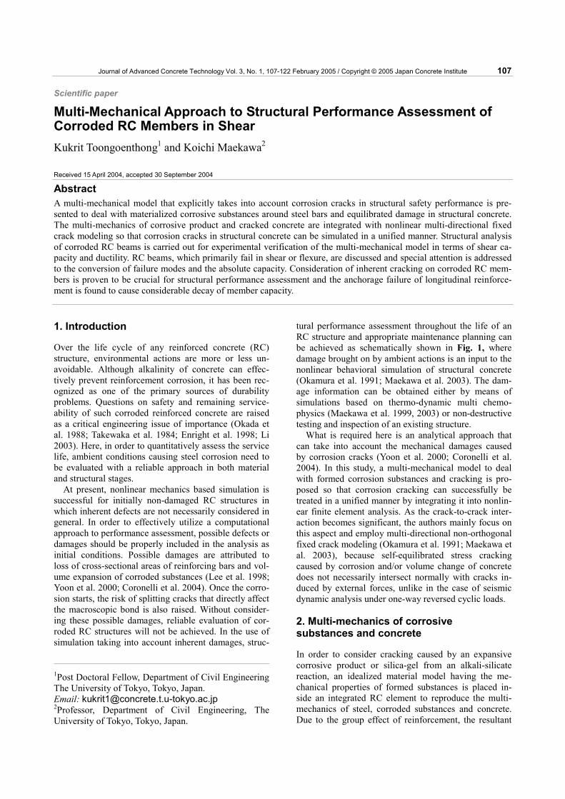
tural performance assessment throughout the life of an RC structure and appropriate maintenance planning can be achieved as schematically shown in Fig. 1, where damage brought on by ambient actions is an input to the nonlinear behavioral simulation of structural concrete (Okamura et al. 1991; Maekawa et al. 2003). The dam-age information can be obtained either by means of simulations based on thermo-dynamic multi chemo-physics (Maekawa et al. 1999, 2003) or non-destructive testing and inspection of an existing structure.
What is required here is an analytical approach that can take into account the mechanical damages caused by corrosion cracks (Yoon et al. 2000; Coronelli et al. 2004). In this study, a multi-mechanical model to deal with formed corrosion substances and cracking is pro-posed so that corrosion cracking can successfully be treated in a unified manner by integrating it into nonlin-ear finite element analysis. As the crack-to-crack inter-action becomes significant, the authors mainly focus on this aspect and employ multi-directional non-orthogonal fixed crack modeling (Okamura et al. 1991; Maekawa et al. 2003), because self-equilibrated stress cracking caused by corrosion and/or volume change of concrete does not necessarily intersect normally with cracks in-duced by external forces, unlike in the case of seismic dynamic analysis under one-way reversed cyclic loads.
2. Multi-mechanics of corrosive substances and concrete
In order to consider cracking caused by an expansive corrosive product or silica-gel from an alkali-silicate reaction, an idealized material model having the me-chanical properties of formed substances is placed in-side an integrated RC element to reproduce the multi-mechanics of steel, corroded substances and concrete. Due to the group effect of reinforcement, the resultant
1Post Doctoral Fellow, Department of Civil EngineeringThe University of Tokyo, Tokyo, Japan. Email: [email protected] 2Professor, Department of Civil Engineering, The University of Tokyo, Tokyo, Japan.
108 K.Toongoenthong and K. Maekawa / Journal of Advanced Concrete Technology Vol. 3, No. 1, 107-122, 2005
force induced by expansive material around steel bars is assumed to be equivalent to the 1-D stress field for criti-cal corrosion cracks, which penetrate the whole sections. Consequently, structural safety related to corrosion cracking can be computed under external forces.
The authors assume a two-phase problem composed of corrosion product with non-corroded steel as one integrated phase and surrounding concrete as another (See Fig. 1 and Fig. 2). When corrosion takes place, the expansion of the rust is constrained by the surrounding concrete. Accordingly, the compressive stress is intro-duced to the corroded reinforcement system, while the tensile stress is induced to the surrounding concrete (Lundgren 2002). Internal equilibrium and deforma-tional compatibility may lead to pre- and post-cracking deformation and stresses. In a pre-crack condition, in-duced tensile stress to concrete may cause cracking if its value exceeds the tensile strength. In a post-cracking state of corrosion, stress transfer across corrosion crack planes may be derived from this multi-mechanical mod-eling.
Figure 2 shows a schematic diagram for the ex-panded geometry of corroded steel and concrete. If there is no restraint on the corrosion product from the sur-rounding concrete, the corrosion product can expand freely with no stress. First, volume loss of the corroded
steel (denoted by Vloss) from the mother steel is calcu-lated by,
42DVloss πγ= (1)
where, D is the steel diameter (m) and γ denotes the volume fraction loss (= mass fraction loss: non-dimension) of steel per unit length ranging from 0 to 1; 0 means no corrosion, while 1 means complete loss of the reinforcement section. The value of γ can be con-verted from the accumulated mass loss per unit surface area of steel (Ω: kg/m2) obtained from the simulation (Maekawa et al. 1999, 2003) as,
Dsteelργ /4Ω= (2)
where, ρsteel is defined as the steel density (~7.65x10³ kg/m3) and the mother steel exhibits smaller diameter due to corrosion loss. The remaining diameter of un-corroded steel (denoted by Dcorroded-steel) yields,
γ−=− 1DD steelcorroded (3)
As the volume loss is converted to expansive corroded product, we have the final volume of corroded product as,
dr
rro
δmaxδm
dr
rro
δmaxδm
DuCOMthermo-dynamic oriented system
Material Information
(by Maekawa, Chaube, Kishi, Ishida)
Material Status considering durability
-corrosion -ASR-carbonation, etc.
Mechanical Behavior
Continuum MechanicsDeformation CompatibilityMomentum Conservation
WCOMD(2D) & COM3(3D)By Okamura and Maekawa
Non-destructive Testing
•Surface Crack Width•Half-cell potential•Resistivity measure•Infrared thermograph•Radiography
Mutual Linkage
Possible cross-check Steel
Concrete Concrete
Mechanical Corrosion ModelRational & unified evaluation
of structural performance
Num
eric
al
corro
sive
cra
ckin
g
Hor. crack
Ver. crackσ
εTension stiffening model
Fig. 1 Rational structural performance assessment of corroded RC.

K.Toongoenthong and K. Maekawa / Journal of Advanced Concrete Technology Vol. 3, No. 1, 107-122, 2005 109
42DVcorr αγπ= (4)
where, α is defined as the coefficient of expansion of corroded substance and reported in literature ranging from 2 to 6 depending on the composition of oxides (Liu and Weyers 1998; Martin-Perez 2000). The cor-roded product consequently forms around the mother steel. The diameter of the corroded reinforcement sys-tem, which consists of mother steel and its corrosive product, is obtained in the case of stress-free and geo-metrically uniform expansion as,
( )11 −+= αγDD yercorrodedla (5)
Then, the reinforcement free-expansion strain (εs, free) of isotropy yields,
( ) 111, −−+= αγε frees (6)
The value stated above is the mean strain of the cor-roded system at the specific level of corrosion ‘γ’. The stress induced by restraint of the surrounding concrete is computed by multiplying the total strain of the corroded system with its average stiffness representing multi-mechanical properties. The average stiffness of the cor-roded system, which is denoted by Es,eq is computed based on the steel and corroded layers. As the corroded system is assumed to be uniform characteristic, the av-erage stiffness of the corroded system can be expressed based upon the volume fraction as,
( )( )GE
E
s
eqsγαγ
αγ
+
−
−+=
111
, (7)
where, G is the stiffness of the corroded substance (~7 GPa) and Es is the stiffness of steel (~200 GPa). Note that the linear relationship of corroded substance is as-sumed in this formulation.
Let us first consider the post-cracking state of corro-sion in a finite element including reinforcement. In fact, the post-cracking model is indispensable to verify struc-tural performance under loads as well as prediction of crack initiation. In this study, the authors direct their attention primarily to the post-crack & multi-mechanics aspects rather than crack initiation. The crack plane is assumed in the transverse direction of the Y-axis as shown in Fig. 2. Here, the normal stress is transferred just through the multi-material system of corroded and non-corroded steel, and shear transfer is chiefly carried along the concrete crack by interlocking. Under the condition of crack separation, incremental normal strain of the control volume can be described as the sum of the concrete and multi-mechanical steel. The stress develop-ing in the corroded steel is nearly inversely proportional to the reinforcement ratio, and the strain field of the multi-mechanical system of corroded steel is a part of the total strain expressed as,
eqs
yy
c
yysyycyy E
dE
dd
,, )1()1(
ψσ
ψψσ
ψψεεψε +−≅+−= (8)
D
Free expansionof rust
steel w/o corrosion
Confined expansionof RC system
where D: Initial steel diameter, γ: Mass fraction loss, α: Rust expansion coefficient
L
L
D L+δ
concrete
( )11 −+ αγD
D+δ
D+δ
steel
σyy
σyys
x
y
Fig. 2 Schematic representation for expansion of corroded steel in RC.
110 K.Toongoenthong and K. Maekawa / Journal of Advanced Concrete Technology Vol. 3, No. 1, 107-122, 2005
where, ψ denotes the ratio of local corroded steel strain over the mean strain in the y-direction. When rein-forcement is assumed to be uniformly suspended in the control volume or a finite element as shown in Fig. 2, we have,
2/1p≅ψ (9)
where, p is defined as the reinforcement ratio by the control volume or a finite element. Then, the element based stiffness of coupled cracked concrete and multi-mechanical corroded steel yields,
yycyyceqs
cyy dEdE
EE
d εψεψψψσ ≅
+−=
−1
,1 (10)
Here, let us consider the free expansion as the control volume after cracking. The transverse stress is equal to zero, the continuum strain of cracked concrete can be assumed to be null, and the corroded steel strain coin-cides with εs, free. In considering the volume ratio of cor-roded steel over the control volume or the finite element, we have p1/2εs, free as the normal expansion free strain of the multi-mechanical system, which consists of cracked concrete, corroded product layers and the non-corroded mother steel. In considering the stress-free strain of the element and the derivative of total stress-strain ex-pressed by Eq. (8), we have,
( )
freesyys
yy
yycfreess
yy
freesyyfreesyycs
yy
E
E
,
2,
,,
0
0
0
εψεσ
εψεσ
εψεεψεψσ
⋅>=
<⋅⋅−=
⋅<≤⋅−⋅= … (11)
where, the total transverse stress becomes null when the total strain exceeds ψεs, free When the transverse strain turns negative, cracks will close and start to transfer compressive normal stress. In this case, cracked con-crete primarily bears the stress transfer, and this stress can be computed based on the smeared crack constitu-tive modeling. Then, the additional stress transferred by the corroded steel in Eq. (11) can be overlaid on the original multi-directional fixed crack approach.
As far as shear transfer across a crack is concerned, corroded steel may play a negligible role compared with that of concrete rough crack interlock. Normal stress transfer in the longitudinal direction is carried by the reinforcement and can be modeled as previously done. Thus, the transverse component of reinforcement stress is added to the conventional framework of multi-directional fixed crack modeling of RC elements (Maekawa et al. 2003). This constitutes the newly pro-posed approach in the spatial averaging scheme of smeared cracks. In this approach, creep of concrete con-tinuum and the non-uniformity of concrete stress field, which are of importance to the pre-crack state, need not be explicitly taken into account since crack kinematics may absorb creep deformation, thus making continuum
deformation of concrete insignificant in relation to the overall deformation. This modeling shall be verified in the post-cracked RC structural behaviors as discussed in the following chapter.
3. Verification in terms of post-cracking member level
In this chapter, the multi-mechanical model for corroded steel system is integrated into the nonlinear finite ele-ment analysis (Okamura and Maekawa 1991; Maekawa et al. 2003). Verification of multi-mechanics is aimed for through the analysis of RC members subjected to combined corrosion and external loads. Numerical simulation of corroded RC members is conducted for flexural and shear modes of failure.
When reinforcement corrosion takes place inside a member, loss of effective reinforcement area is observed. When corrosion advances further, the tensile stress in-side the surrounding concrete is raised due to self-equilibrated force to restrain the expansion of corrosive product. After a critical stress, cracking occurs along main reinforcing bars and macroscopic bond deteriora-tion is initiated since the layer of steel and the concrete beam web are mechanically divided. Here, the loss of corroded steel sectional area is simply represented as a reduced reinforcement ratio in numerical analysis. The bond loss (Auyeung et al. 2000; Coronelli 2002; Stanish et al. 1999) associated with longitudinal cracking along the main reinforcement is represented by a degradation in tension stiffening, which represents the ability to carry a certain amount of tension transferred from the reinforcement to concrete between cracks.
In this study, macroscopic bond deterioration is me-chanically considered through the section-penetrating corrosion cracking as previously stated, and the micro-scopic bond deterioration around the main reinforce-ment is represented by an altered tension stiffening pa-rameter (Okamura and Maekawa 1991; Maekawa et al. 2003). Finally, the effect of cracking damage on the resultant member capacity is considered by employing the multi-mechanical model introduced in the nonlinear analysis as,
=
=
+=
0),(
)()(
),()(
sxy
yys
yy
xxs
xx
kls
ij
kls
ijklc
ijij
σγεσ
εσεσ
εσεσσ
(12)
where, σijc is the concrete stress with cracking and for-mulated by the multi-directional fixed crack modeling (Okamura and Maekawa 1991; Maekawa et al. 2003) and σijs is the mean stress component carried by the reinforcement steel. When the longitudinal direction is specified as the X-axis, σxx
sdenotes the longitudinal steel stress and is computed in terms of the mean normal strain of the element along the reinforcement. Stress
K.Toongoenthong and K. Maekawa / Journal of Advanced Concrete Technology Vol. 3, No. 1, 107-122, 2005 111
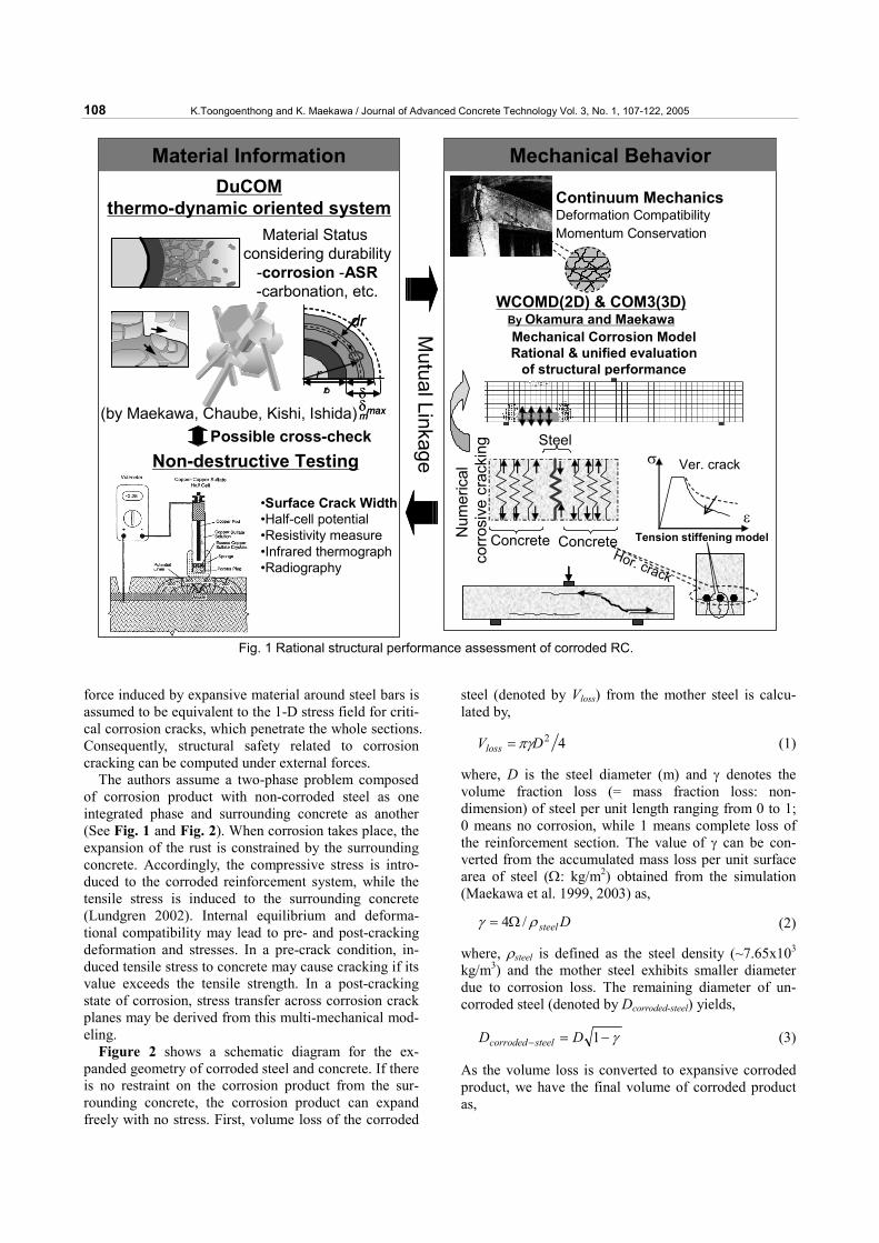
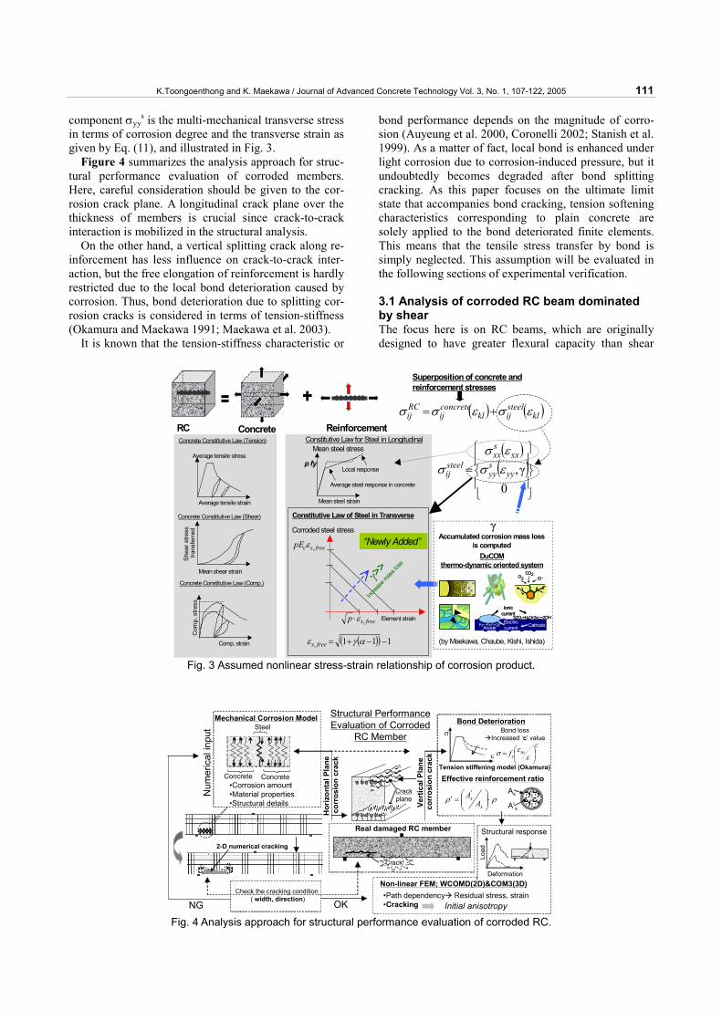
component σyys is the multi-mechanical transverse stress
in terms of corrosion degree and the transverse strain as given by Eq. (11), and illustrated in Fig. 3.
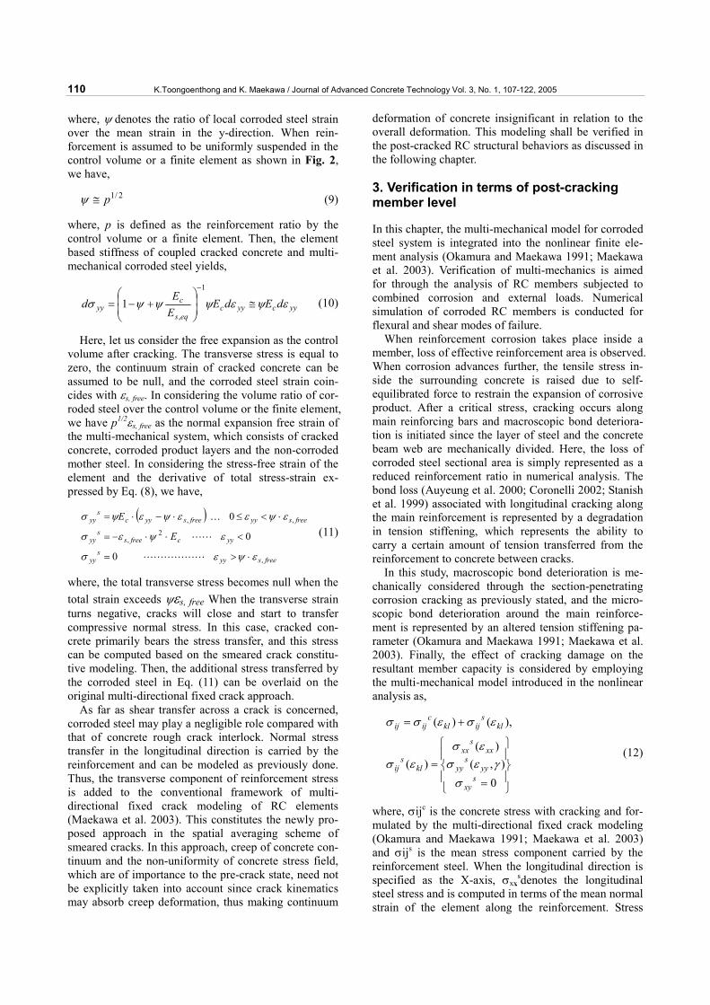
Figure 4 summarizes the analysis approach for struc-tural performance evaluation of corroded members. Here, careful consideration should be given to the cor-rosion crack plane. A longitudinal crack plane over the thickness of members is crucial since crack-to-crack interaction is mobilized in the structural analysis.
On the other hand, a vertical splitting crack along re-inforcement has less influence on crack-to-crack inter-action, but the free elongation of reinforcement is hardly restricted due to the local bond deterioration caused by corrosion. Thus, bond deterioration due to splitting cor-rosion cracks is considered in terms of tension-stiffness (Okamura and Maekawa 1991; Maekawa et al. 2003).
It is known that the tension-stiffness characteristic or
bond performance depends on the magnitude of corro-sion (Auyeung et al. 2000, Coronelli 2002; Stanish et al. 1999). As a matter of fact, local bond is enhanced under light corrosion due to corrosion-induced pressure, but it undoubtedly becomes degraded after bond splitting cracking. As this paper focuses on the ultimate limit state that accompanies bond cracking, tension softening characteristics corresponding to plain concrete are solely applied to the bond deteriorated finite elements. This means that the tensile stress transfer by bond is simply neglected. This assumption will be evaluated in the following sections of experimental verification. 3.1 Analysis of corroded RC beam dominated by shear The focus here is on RC beams, which are originally designed to have greater flexural capacity than shear
Constitutive Law of Steel in Transverse
γ>>
Increa
se m
ass l
oss
( )( ) 111, −−+= αγε frees
RC Concrete Reinforcement
Mean steel stress
Mean steel strain
Average steel response in concrete
Local response
Constitutive Law for Steel in Longitudinal
Corroded steel stress
Element strain
“Newly Added”
Concrete Constitutive Law (Tension)
Concrete Constitutive Law (Shear)
Concrete Constitutive Law (Comp.)
Average tensile stress
Average tensile strain
She
ar s
tress
trans
ferr
ed
Mean shear strain
Com
p. s
tress
Comp. strain
DuCOMthermo-dynamic oriented system
(by Maekawa, Chaube, Kishi, Ishida)
γAccumulated corrosion mass loss
is computed
( ) ( )klsteelijkl
concreteij
RCij εσεσσ +=
( )( )
=0
γ,yysyy
xxsxx
steelij εσ
εσσ
Superposition of concrete and reinforcement stresses
Fe→Fe2++2e-
Ionic current
Electric currentAnode Cathode
1/2O2+H2O+2e-→2OH-
Fe→Fe2++2e-
Ionic current
Electric currentAnode Cathode
1/2O2+H2O+2e-→2OH-
O2O2 Cl‐Cl‐CO2CO2
freescpE ,ε
freesp ,ε⋅
p fy
Fig. 3 Assumed nonlinear stress-strain relationship of corrosion product.
Steel
Concrete Concrete•Corrosion amount•Material properties•Structural details
Num
eric
al in
put
2-D numerical cracking
Mechanical Corrosion Model
Real damaged RC member
Check the cracking condition ( width, direction)
Hor
izon
tal P
lane
corr
osio
n cr
ack
Crackplane
Crack!
Vert
ical
Pla
neco
rros
ion
crac
k
Bond Deteriorationσ
εTension stiffening model (Okamura)
Ctu
tf
= εεσ
Bond lossIncreased ‘c’ value
Effective reinforcement ratio
ρρ ⋅
=′
ss
AA' As
A’s
OKNG
Non-linear FEM; WCOMD(2D)&COM3(3D)•Path dependency Residual stress, strain•Cracking Initial anisotropy
Structural response
Load
Deformation
Structural PerformanceEvaluation of Corroded
RC Member
Fig. 4 Analysis approach for structural performance evaluation of corroded RC.
112 K.Toongoenthong and K. Maekawa / Journal of Advanced Concrete Technology Vol. 3, No. 1, 107-122, 2005
strength. Thus the shear resistance mechanism is of sig-nificant importance and subjected to longitudinal crack-ing by corrosion. Actually, it was confirmed by Piman-mas and Maekawa (2001) that there exists a strong in-teraction of non-orthogonal cracks in the shear behav-iors of RC members. The shear capacity of corroded RC beams with longitudinal deep cracking in space was also experimentally investigated and the significance of the location of these partial local damages was clarified (Toongoenthong and Maekawa 2004). The effect of lo-cal longitudinal cracking on shear capacity of RC dam-aged members can be adverse, insignificant or even favorable, depending upon the specific damage location in space and member structural detail (Toongoenthong et al. 2004).
Consequently, non-linear analyses that can take into account corrosion cracking may carry greater weight. Following are the authors’ analyses of damaged RC beams with partial corrosion and artificial defects for magnifying the mechanical effect of corrosion cracks. In order to verify the applicability of the developed nonlin-ear FEM chiefly with regard to crack-to-crack interac-
tion, RC beams with different patterns of local cracking and defects are analyzed by employing the multi-mechanical corrosion model.
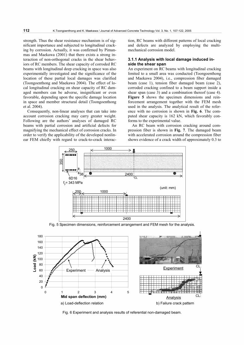
3.1.1 Analysis with local damage induced in-side the shear span An experiment on RC beams with longitudinal cracking limited to a small area was conducted (Toongoenthong and Maekawa 2004), i.e., compression fiber damaged beam (case 1), tension fiber damaged beam (case 2), corroded cracking confined to a beam support inside a shear span (case 3) and a combination thereof (case 4). Figure 5 shows the specimen dimensions and rein-forcement arrangement together with the FEM mesh used in the analysis. The analytical result of the refer-ence with no corrosion is shown in Fig. 6. The com-puted shear capacity is 162 kN, which favorably con-forms to the experimental value.
An RC beam with corrosion cracking around com-pression fiber is shown in Fig. 7. The damaged beam with accelerated corrosion around the compression fiber shows evidence of a crack width of approximately 0.3 to
1000200
2400
1000250
350
24006D16
fy= 343 MPa(unit: mm)
38CL
Fig. 5 Specimen dimensions, reinforcement arrangement and FEM mesh for the analysis.
0
20
40
60
80
100
120
140
160
180
0 1 2 3 4 5Mid span deflection (mm)
Load
(kN
)
Experiment Analysis
CL.
CL.Experiment
Analysis a) Load-deflection relation b) Failure crack pattern
Fig. 6 Experiment and analysis results of referential non-damaged beam.
K.Toongoenthong and K. Maekawa / Journal of Advanced Concrete Technology Vol. 3, No. 1, 107-122, 2005 113
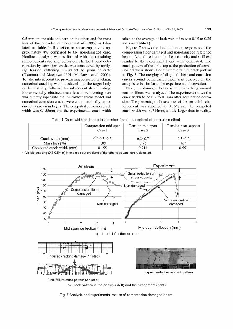
0.5 mm on one side and zero on the other, and the mass loss of the corroded reinforcement of 1.89% as tabu-lated in Table 1. Reduction in shear capacity is ap-proximately 8% compared to the non-damaged case. Nonlinear analysis was performed with the remaining reinforcement ratio after corrosion. The local bond dete-rioration by corrosion cracks was considered by apply-ing tension stiffening equivalent to plain concrete (Okamura and Maekawa 1991; Maekawa et al. 2003). To take into account the pre-existing corrosion cracking, numerical cracking was introduced into the target body in the first step followed by subsequent shear loading. Experimentally obtained mass loss of reinforcing bars was directly input into the multi-mechanical model and numerical corrosion cracks were computationally repro-duced as shown in Fig. 7. The computed corrosion crack width was 0.155mm and the experimental crack width
taken as the average of both web sides was 0.15 to 0.25 mm (see Table 1).
Figure 7 shows the load-deflection responses of the compression fiber damaged and non-damaged reference beams. A small reduction in shear capacity and stiffness similar to the experimental one were computed. The crack pattern of the first step at the production of corro-sion cracks is shown along with the failure crack pattern in Fig. 7. The merging of diagonal shear and corrosion cracks around compression fiber was observed in the analysis to be similar to the experimental observation.
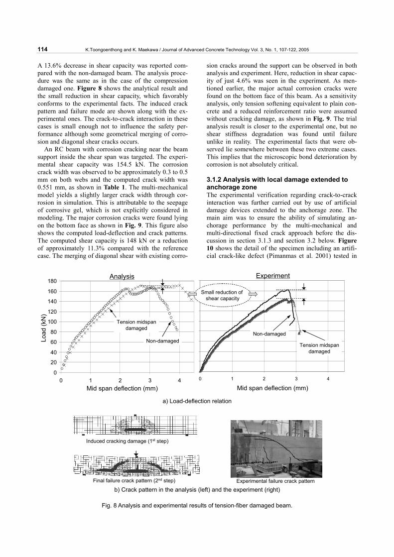
Next, the damaged beam with pre-cracking around tension fibers was analyzed. The experiment shows the crack width to be 0.2 to 0.7mm after accelerated corro-sion. The percentage of mass loss of the corroded rein-forcement was reported as 8.76% and the computed crack width was 0.714mm, a little larger than in reality.
Table 1 Crack width and mass loss of steel from the accelerated corrosion method.
Compression mid-spanCase 1
Tension mid-span Case 2
Tension near support Case 3
Crack width (mm) 0*)~0.3~0.5 0.2~0.7 0.3~0.5 Mass loss (%) 1.89 8.76 6.7
Computed crack width (mm) 0.155 0.714 0.551 *) Visible cracking (0.3-0.5mm) in one side but cracking of the other side was hardly detected.
0
20
40
60
80
100
120
140
160
180
0 1 2 3 4
Mid Deflection(mm)
Load
(kN)
0
20
40
60
80
100
120
140
160
180
0 1 2 3 4mid span deflection(mm)
Load
(kN
)
Analysis Experiment
Non-damaged
Compression-fiberdamaged
Non-damaged
Compression-fiberdamaged
Small reduction of shear capacity
Mid span deflection (mm) Mid span deflection (mm)
Load
(kN
)
a) Load-deflection relation
Induced cracking damage (1st step)
Final failure crack pattern (2nd step)
Experimental failure crack pattern
b) Crack pattern in the analysis (left) and the experiment (right)
Fig. 7 Analysis and experimental results of compression damaged beam.
114 K.Toongoenthong and K. Maekawa / Journal of Advanced Concrete Technology Vol. 3, No. 1, 107-122, 2005
A 13.6% decrease in shear capacity was reported com-pared with the non-damaged beam. The analysis proce-dure was the same as in the case of the compression damaged one. Figure 8 shows the analytical result and the small reduction in shear capacity, which favorably conforms to the experimental facts. The induced crack pattern and failure mode are shown along with the ex-perimental ones. The crack-to-crack interaction in these cases is small enough not to influence the safety per-formance although some geometrical merging of corro-sion and diagonal shear cracks occurs.
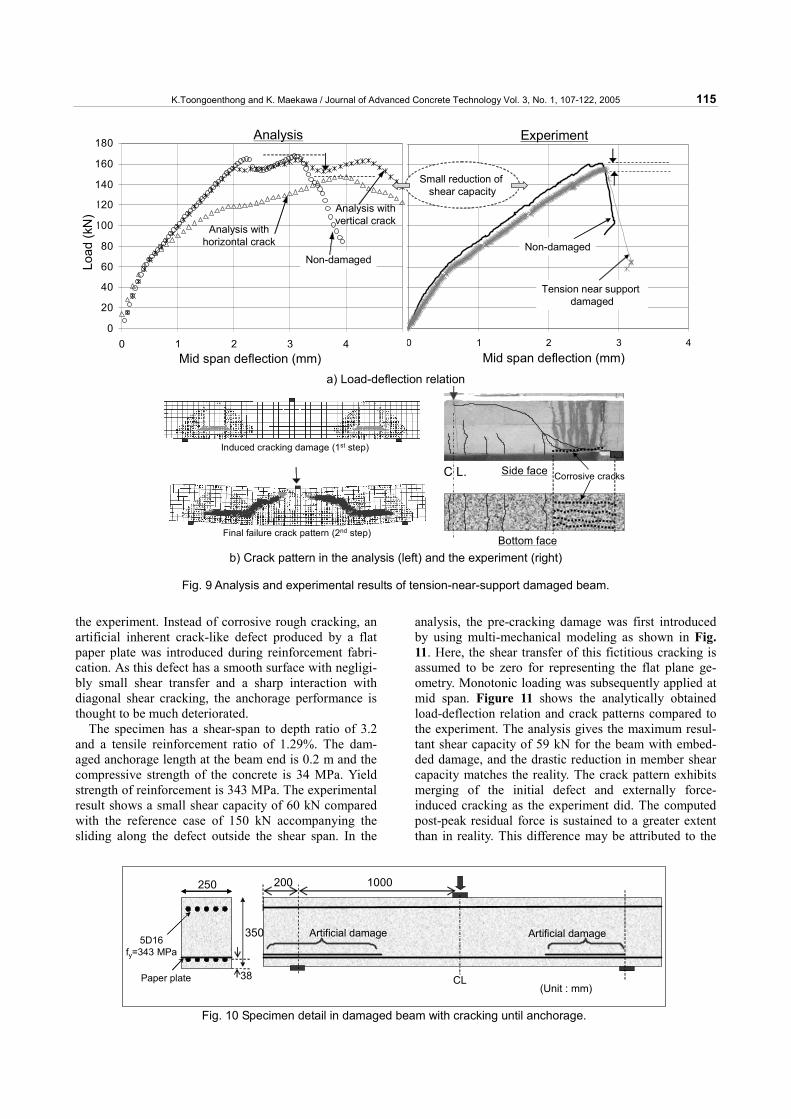
An RC beam with corrosion cracking near the beam support inside the shear span was targeted. The experi-mental shear capacity was 154.5 kN. The corrosion crack width was observed to be approximately 0.3 to 0.5 mm on both webs and the computed crack width was 0.551 mm, as shown in Table 1. The multi-mechanical model yields a slightly larger crack width through cor-rosion in simulation. This is attributable to the seepage of corrosive gel, which is not explicitly considered in modeling. The major corrosion cracks were found lying on the bottom face as shown in Fig. 9. This figure also shows the computed load-deflection and crack patterns. The computed shear capacity is 148 kN or a reduction of approximately 11.3% compared with the reference case. The merging of diagonal shear with existing corro-
sion cracks around the support can be observed in both analysis and experiment. Here, reduction in shear capac-ity of just 4.6% was seen in the experiment. As men-tioned earlier, the major actual corrosion cracks were found on the bottom face of this beam. As a sensitivity analysis, only tension softening equivalent to plain con-crete and a reduced reinforcement ratio were assumed without cracking damage, as shown in Fig. 9. The trial analysis result is closer to the experimental one, but no shear stiffness degradation was found until failure unlike in reality. The experimental facts that were ob-served lie somewhere between these two extreme cases. This implies that the microscopic bond deterioration by corrosion is not absolutely critical. 3.1.2 Analysis with local damage extended to anchorage zone The experimental verification regarding crack-to-crack interaction was further carried out by use of artificial damage devices extended to the anchorage zone. The main aim was to ensure the ability of simulating an-chorage performance by the multi-mechanical and multi-directional fixed crack approach before the dis-cussion in section 3.1.3 and section 3.2 below. Figure 10 shows the detail of the specimen including an artifi-cial crack-like defect (Pimanmas et al. 2001) tested in
0
20
40
60
80
100
120
140
160
180
0 1 2 3 4
Mid Deflection(mm)
Load
(kN)
0
20
40
60
80
100
120
140
160
180
0 1 2 3 4mid span deflection(mm)
Load
(kN
)
Analysis Experiment
Small reduction of shear capacity
Non-damagedNon-damaged
Tension midspandamaged
Tension midspandamaged
Load
(kN
)
Mid span deflection (mm) Mid span deflection (mm)
a) Load-deflection relation
Induced cracking damage (1st step)
Final failure crack pattern (2nd step) Experimental failure crack pattern b) Crack pattern in the analysis (left) and the experiment (right)
Fig. 8 Analysis and experimental results of tension-fiber damaged beam.
K.Toongoenthong and K. Maekawa / Journal of Advanced Concrete Technology Vol. 3, No. 1, 107-122, 2005 115
the experiment. Instead of corrosive rough cracking, an artificial inherent crack-like defect produced by a flat paper plate was introduced during reinforcement fabri-cation. As this defect has a smooth surface with negligi-bly small shear transfer and a sharp interaction with diagonal shear cracking, the anchorage performance is thought to be much deteriorated.
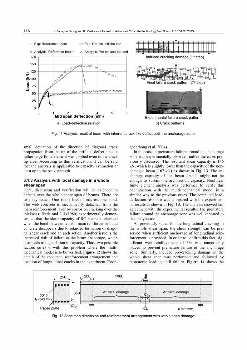
The specimen has a shear-span to depth ratio of 3.2 and a tensile reinforcement ratio of 1.29%. The dam-aged anchorage length at the beam end is 0.2 m and the compressive strength of the concrete is 34 MPa. Yield strength of reinforcement is 343 MPa. The experimental result shows a small shear capacity of 60 kN compared with the reference case of 150 kN accompanying the sliding along the defect outside the shear span. In the
analysis, the pre-cracking damage was first introduced by using multi-mechanical modeling as shown in Fig. 11. Here, the shear transfer of this fictitious cracking is assumed to be zero for representing the flat plane ge-ometry. Monotonic loading was subsequently applied at mid span. Figure 11 shows the analytically obtained load-deflection relation and crack patterns compared to the experiment. The analysis gives the maximum resul-tant shear capacity of 59 kN for the beam with embed-ded damage, and the drastic reduction in member shear capacity matches the reality. The crack pattern exhibits merging of the initial defect and externally force-induced cracking as the experiment did. The computed post-peak residual force is sustained to a greater extent than in reality. This difference may be attributed to the
0
20
40
60
80
100
120
140
160
180
0 1 2 3 4
Mid Deflection(mm)Lo
ad(k
N)
0
20
40
60
80
100
120
140
160
180
0 1 2 3 4 5mid span deflection(mm)
Load
(kN
)
Analysis with horizontal crack
Analysis with vertical crack
Small reduction of shear capacity
Non-damaged
Analysis Experiment
Non-damaged
Tension near support damaged
Load
(kN
)
Mid span deflection (mm) Mid span deflection (mm) a) Load-deflection relation
Induced cracking damage (1st step)
Final failure crack pattern (2nd step)
C L. Side face
Bottom face
Corrosive cracks
b) Crack pattern in the analysis (left) and the experiment (right)
Fig. 9 Analysis and experimental results of tension-near-support damaged beam.
5D16fy=343 MPa
Paper plate
350
250 1000
Artificial damage Artificial damage
(Unit : mm)CL
200
38
Fig. 10 Specimen detail in damaged beam with cracking until anchorage.
116 K.Toongoenthong and K. Maekawa / Journal of Advanced Concrete Technology Vol. 3, No. 1, 107-122, 2005
small deviation of the direction of diagonal crack propagation from the tip of the artificial defect since a rather large finite element was applied even in the crack tip area. According to this verification, it can be said that the analysis is applicable to capacity estimation at least up to the peak strength.
3.1.3 Analysis with local damage in a whole shear span Here, discussion and verification will be extended to defects over the whole shear span of beams. There are two key issues. One is the loss of macroscopic bond. The web concrete is mechanically detached from the main reinforcement layer by corrosion cracking over the thickness. Ikeda and Uji (1980) experimentally demon-strated that the shear capacity of RC beams is elevated when the bond between tension main reinforcement and concrete disappears due to retarded formation of diago-nal shear crack and an arch action. Another issue is the increased risk of failure at the beam anchorage, which also leads to degradation in capacity. Thus, two possible factors co-exist with this problem where the multi-mechanical model is to be verified. Figure 12 shows the details of the specimen, reinforcement arrangement and location of longitudinal cracks in the experiment (Toon-
goenthong et al. 2004). In this case, a premature failure around the anchorage
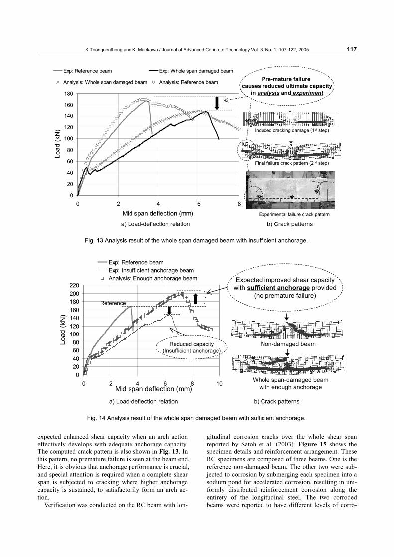
zone was experimentally observed unlike the cases pre-viously discussed. The resultant shear capacity is 146 kN, which is slightly lower than the capacity of the non-damaged beam (167 kN) as shown in Fig. 13. The an-chorage capacity of the beam details might not be enough to sustain the arch action capacity. Nonlinear finite element analysis was performed to verify this phenomenon with the multi-mechanical model in a similar way to the previous cases. The computed load-deflection response was compared with the experimen-tal results as shown in Fig. 13. The analysis showed fair agreement with the experimental results. The premature failure around the anchorage zone was well captured in the analysis too.
As previously stated for the longitudinal cracking in the whole shear span, the shear strength can be pre-served when sufficient anchorage of longitudinal rein-forcement is provided. In order to confirm this fact, sig-nificant web reinforcement of 3% was numerically placed to prevent premature failure of the anchorage zone. Similarly, induced pre-cracking damage in the whole shear span was performed and followed by monotonic loading until failure. Figure 14 shows the
0
25
50
75
100
125
150
175
0 1 2 3 4 5 6Mid span deflection (mm)
Load
(kN
)
Exp: Reference beam Exp: Pre-crk until the end
Analysis: Reference beam Analysis: Pre-crk until the end
Induced cracking damage (1st step)
Final failure crack pattern (2nd step)
Experimental failure crack pattern a) Load-deflection relation b) Crack patterns
Fig. 11 Analysis result of beam with inherent crack-like defect until the anchorage zone.
5D16fy=343 MPa
Paper plate
350
250 1000
Artificial damage Artificial damage
(Unit: mm)CL
200
150
38
Fig. 12 Specimen dimension and reinforcement arrangement with whole span damage.
K.Toongoenthong and K. Maekawa / Journal of Advanced Concrete Technology Vol. 3, No. 1, 107-122, 2005 117
expected enhanced shear capacity when an arch action effectively develops with adequate anchorage capacity. The computed crack pattern is also shown in Fig. 13. In this pattern, no premature failure is seen at the beam end. Here, it is obvious that anchorage performance is crucial, and special attention is required when a complete shear span is subjected to cracking where higher anchorage capacity is sustained, to satisfactorily form an arch ac-tion.
Verification was conducted on the RC beam with lon-
gitudinal corrosion cracks over the whole shear span reported by Satoh et al. (2003). Figure 15 shows the specimen details and reinforcement arrangement. These RC specimens are composed of three beams. One is the reference non-damaged beam. The other two were sub-jected to corrosion by submerging each specimen into a sodium pond for accelerated corrosion, resulting in uni-formly distributed reinforcement corrosion along the entirety of the longitudinal steel. The two corroded beams were reported to have different levels of corro-
0
20
40
60
80
100
120
140
160
180
0 2 4 6 8
Mid span deflection (mm)
Load
(kN
)
Exp: Reference beam Exp: Whole span damaged beam
Analysis: Whole span damaged beam Analysis: Reference beam
Induced cracking damage (1st step)
Final failure crack pattern (2nd step)
Experimental failure crack pattern
Pre-mature failure causes reduced ultimate capacity
in analysis and experiment
a) Load-deflection relation b) Crack patterns
Fig. 13 Analysis result of the whole span damaged beam with insufficient anchorage.
020406080
100120140160180200220
0 2 4 6 8 10Mid span deflection (mm)
Load
(kN
)
Exp: Reference beamExp: Insufficient anchorage beamAnalysis: Enough anchorage beam
Non-damaged beam
Whole span-damaged beamwith enough anchorage
Reduced capacity(Insufficient anchorage)
Reference
Expected improved shear capacitywith sufficient anchorage provided
(no premature failure)
a) Load-deflection relation b) Crack patterns
Fig. 14 Analysis result of the whole span damaged beam with sufficient anchorage.

118 K.Toongoenthong and K. Maekawa / Journal of Advanced Concrete Technology Vol. 3, No. 1, 107-122, 2005
sion along the main reinforcement. The lightly corroded beam had a mass loss of 2.1% and heavily corroded beam had a mass loss of 3.3%. In this experiment, the main reinforcing bars were bent up 90 degree inside the anchorage zone as shown in Fig. 15. Thus, a satisfactory anchorage capacity is expected is spite of the existence of corrosion.
Figure 16 shows the experimental load-displacement relation and crack pattern of all RC specimens. Both corroded beams show a favorable shear capacity com-pared with the non-damaged beam. As illustrated also in Fig. 16, there are clear differences in failure crack pat-terns between the two corroded damaged beams and the non-damaged reference beam. Although the diagonal shear failure was observed in the non-damaged beam, no localized diagonal shear crack was formed in the case of the lightly corroded beam.
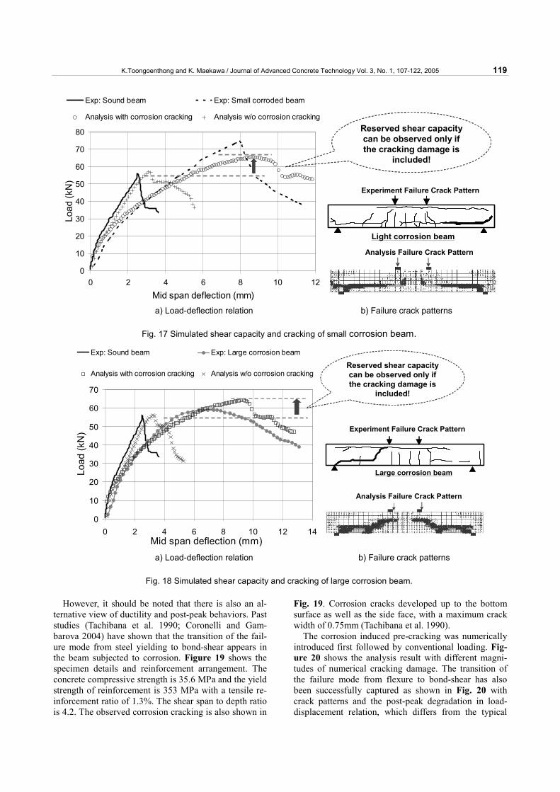
Similar to the previous cases of analysis, the target specimens were analyzed by introducing numerical pre-cracking at the location similar to the experiment in the first step of analysis. Then the monotonic load was ap-plied until failure. Figure 17 and Fig. 18 show the load-displacement relations and failure crack patterns ob-
tained for the cases of the lightly and heavily corroded beams, respectively. It can be seen that the analytical results of both cases are in good agreement with the experimental facts in both the load-displacement curves and failure crack patterns. Furthermore, analysis of both corroded beams without pre-corrosive-cracking was also performed to ensure the significance of the analyti-cal approach by considering only the reduced rein-forcement ratio and tension stiffening. As illustrated in Fig. 17 and Fig. 18, the analysis result without consider-ing pre-cracking is clearly far off the experimental fact.
3.2 Analysis of corroded RC beam in flexure It is numerically confirmed that longitudinal corrosion cracking can be insignificant, adverse or even favorable on resultant shear capacity and that it depends upon the damage location and structural details. It is also known that flexural capacity is closely associated with the re-maining sectional areas of steel (Rodriguez et al. 1997; Lee et al. 1998; Mangat et al. 1999). In other words, corrosion cracking has small influence on the flexural capacity.
20
100
200
150650
CL.
2-D16fy=295 MPa
D6@50fy=295 MPa
100(Unit: mm)
Fig. 15 Specimen detail and reinforcement arrangement by Satoh et al. (2003).
Sound beamSmall corrosion beamLarge corrosion beam
Load
(kN
)
Displacement (mm)105
pw=0.00%
80
60
40
20
0 5 10
Sound beamSmall corrosion beamLarge corrosion beam
Load
(kN
)
Displacement (mm)105
pw=0.00%
80
60
40
20
0 5 10
Light corrosion beam
Heavy corrosion beam
Sound beam
a) Experimental load-deflection relation b) Failure crack patterns
Fig. 16 Behaviors of corroded beams by Sato et al. (2003).
K.Toongoenthong and K. Maekawa / Journal of Advanced Concrete Technology Vol. 3, No. 1, 107-122, 2005 119
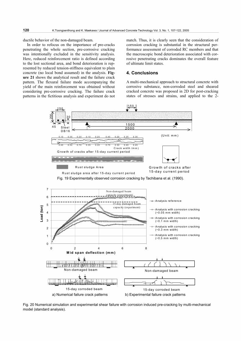
However, it should be noted that there is also an al-ternative view of ductility and post-peak behaviors. Past studies (Tachibana et al. 1990; Coronelli and Gam-barova 2004) have shown that the transition of the fail-ure mode from steel yielding to bond-shear appears in the beam subjected to corrosion. Figure 19 shows the specimen details and reinforcement arrangement. The concrete compressive strength is 35.6 MPa and the yield strength of reinforcement is 353 MPa with a tensile re-inforcement ratio of 1.3%. The shear span to depth ratio is 4.2. The observed corrosion cracking is also shown in
Fig. 19. Corrosion cracks developed up to the bottom surface as well as the side face, with a maximum crack width of 0.75mm (Tachibana et al. 1990).
The corrosion induced pre-cracking was numerically introduced first followed by conventional loading. Fig-ure 20 shows the analysis result with different magni-tudes of numerical cracking damage. The transition of the failure mode from flexure to bond-shear has also been successfully captured as shown in Fig. 20 with crack patterns and the post-peak degradation in load-displacement relation, which differs from the typical
0
10
20
30
40
50
60
70
80
0 2 4 6 8 10 12Mid span deflection (mm)
Load
(kN
)
Exp: Sound beam Exp: Small corroded beam
Analysis with corrosion cracking Analysis w/o corrosion crackingReserved shear capacity can be observed only if the cracking damage is
included!
Light corrosion beam
Experiment Failure Crack Pattern
Analysis Failure Crack Pattern
a) Load-deflection relation b) Failure crack patterns
Fig. 17 Simulated shear capacity and cracking of small corrosion beam.
0
10
20
30
40
50
60
70
0 2 4 6 8 10 12 14Mid span deflection (mm)
Load
(kN
)
Exp: Sound beam Exp: Large corrosion beam
Analysis with corrosion cracking Analysis w/o corrosion crackingReserved shear capacity can be observed only if the cracking damage is
included!
Large corrosion beam
Experiment Failure Crack Pattern
Analysis Failure Crack Pattern
a) Load-deflection relation b) Failure crack patterns
Fig. 18 Simulated shear capacity and cracking of large corrosion beam.
120 K.Toongoenthong and K. Maekawa / Journal of Advanced Concrete Technology Vol. 3, No. 1, 107-122, 2005
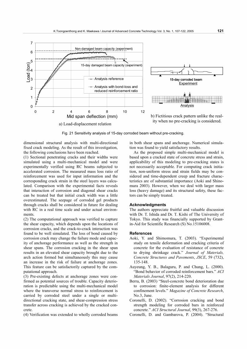
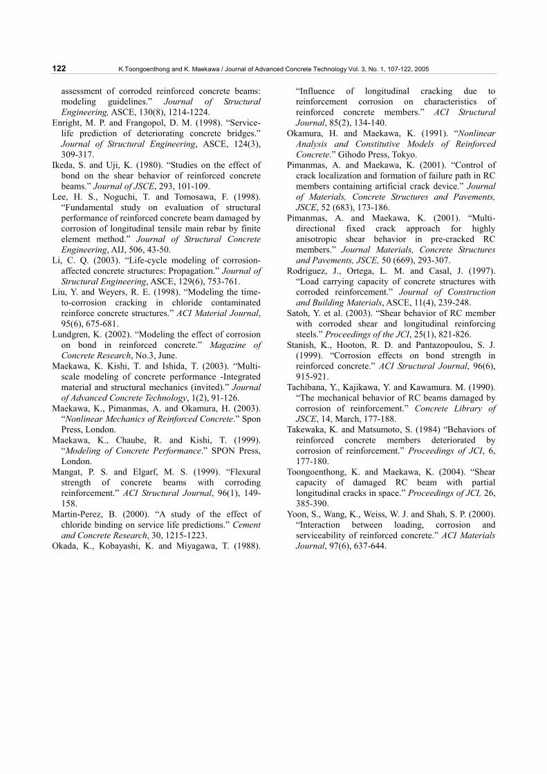
ductile behavior of the non-damaged beam. In order to refocus on the importance of pre-cracks
penetrating the whole section, pre-corrosive cracking was intentionally excluded in the sensitivity analysis. Here, reduced reinforcement ratio is defined according to the lost sectional area, and bond deterioration is rep-resented by reduced tension-stiffness equivalent to plain concrete (no local bond assumed) in the analysis. Fig-ure 21 shows the analytical result and the failure crack pattern. The flexural failure mode accompanying the yield of the main reinforcement was obtained without considering pre-corrosive cracking. The failure crack patterns in the fictitious analysis and experiment do not
match. Thus, it is clearly seen that the consideration of corrosion cracking is substantial in the structural per-formance assessment of corroded RC members and that the macroscopic bond deterioration associated with cor-rosive penetrating cracks dominates the overall feature of ultimate limit states.
4. Conclusions
A multi-mechanical approach to structural concrete with corrosive substance, non-corroded steel and sheared cracked concrete was proposed in 2D for post-cracking states of stresses and strains, and applied to the 2-
1 5 0 02 0 0 0
200
3 0
1 5 0
4 5 S te e lD B 1 6
1 5 0
(U n it: m m )
C ra ck w id th (m m )G ro w th o f c rac ks a fte r 1 5 -d a y c u rren t pe r iod
R u s t s lud g e A rea
R us t s lud g e a re a a fte r 1 5 -d a y cu rren t pe r iod
G ro w th o f c ra ck s a fte r1 5 -d a y c u rre n t p e rio d
0.1 0 0 .3 5 0 .2 0 0 .10 0 .2 5 0 .4 0 0 .2 0 0 .2 5 0 .35
0 .4 0 0 .5 0 0 .7 0 0 .35 0 .3 5 0 .7 5 0 .5 0 0 .4 0 0 .45
Fig. 19 Experimentally observed corrosion cracking by Tachibana et al. (1990).
0
1
2
3
4
5
6
7
0 2 4 6 8M id span deflection (m m )
Load
(ton
)
A nalys is re fe rence
A nalys is with corros ion cracking(~0 .05 m m wid th)
A nalys is with corros ion cracking(~0 .1 m m wid th)
A nalys is with corros ion cracking(~0 .3 m m wid th)
A nalys is with corros ion cracking(~0 .5 m m wid th)
Non-d amaged b eamcapac ity (exp eriment)
15-d ay damaged b eamcap ac ity (experiment)
Non-damaged beam
15-day corroded beam
Non-damaged beam
15-day corroded beam a) Numerical failure crack patterns b) Experimental failure crack patterns
Fig. 20 Numerical simulation and experimental shear failure with corrosion induced pre-cracking by multi-mechanical model (standard analysis).
K.Toongoenthong and K. Maekawa / Journal of Advanced Concrete Technology Vol. 3, No. 1, 107-122, 2005 121
dimensional structural analysis with multi-directional fixed crack modeling. As the result of this investigation, the following conclusions have been reached. (1) Sectional penetrating cracks and their widths were simulated using a multi-mechanical model and were experimentally verified using RC beams subjected to accelerated corrosion. The measured mass loss ratio of reinforcement was used for input information and the corresponding crack strain in the steel layers was calcu-lated. Comparison with the experimental facts reveals that interaction of corrosion and diagonal shear cracks can be treated but that initial crack width was a little overestimated. The seepage of corroded gel products through cracks shall be considered in future for dealing with RC in a real time scale and under actual environ-ments. (2) The computational approach was verified to capture the shear capacity, which depends upon the locations of corrosion cracks, and the crack-to-crack interaction was found to be well simulated. The loss of bond caused by corrosion crack may change the failure mode and capac-ity of anchorage performance as well as the strength in shear spans. The corrosion cracking in the shear span results in an elevated shear capacity brought due to the arch action formed but simultaneously this may cause an increase in the risk of failure at anchorage zones. This feature can be satisfactorily captured by the com-putational approach. (3) Pre-existing defects at anchorage zones were con-firmed as potential sources of trouble. Capacity deterio-ration is predictable using the multi-mechanical model where the transverse normal stress to reinforcement is carried by corroded steel under a single or multi-directional cracking state, and shear-compression stress transfer across cracking is achieved by the cracked con-crete. (4) Verification was extended to wholly corroded beams
in both shear spans and anchorage. Numerical simula-tion was found to yield satisfactory results.
As the proposed simple multi-mechanical model is based upon a cracked state of concrete stress and strain, applicability of this modeling to pre-cracking states is not necessarily acceptable. For computing crack initia-tion, non-uniform stress and strain fields may be con-sidered and time-dependent creep and fracture charac-teristics are of substantial importance (Aoki and Shino-mura 2003). However, when we deal with larger mass loss (heavy damage) and its structural safety, these fac-tors can be simply treated. Acknowledgments The authors appreciate fruitful and valuable discussion with Dr. T. Ishida and Dr. T. Kishi of The University of Tokyo. This study was financially supported by Grant-in-Aid for Scientific Research (S) No.15106008. References Aoki, Y. and Shimomura, T. (2003). “Experimental
study on tensile deformation and cracking criteria of concrete for the evaluation of resistance of concrete to drying shrinkage crack.” Journal of Materials, Concrete Structures and Pavements, JSCE, 59 (732), 135-148.
Auyeung, Y. B., Balaguru, P. and Chung, L. (2000). “Bond behavior of corroded reinforcement bars.” ACI Materials Journal, 97(2), 214-220.
Berra, B. (2003) “Steel-concrete bond deterioration due to corrosion: finite-element analysis for different confinement levels.” Magazine of Concrete Research, No.3, June.
Coronelli, D. (2002). “Corrosion cracking and bond strength modeling for corroded bars in reinforced concrete.” ACI Structural Journal, 99(3), 267-276.
Coronelli, D. and Gambarova, P. (2004). “Structural
0
1
2
3
4
5
6
7
0 2 4 6 8 10 12Mid span deflection (mm)
Load
(ton
)
Analysis reference
Analysis with bond-loss andreduced reinforcement ratio
Non-damaged beam capacity (experiment)
15-day damaged beam capacity (experiment)
a) Load-displacement relation
Experiment
Analysis
15-day corroded beam15-day corroded beam
b) Fictitious crack pattern unlike the real-ity when no pre-cracking is considered.
Fig. 21 Sensitivity analysis of 15-day corroded beam without pre-cracking.
122 K.Toongoenthong and K. Maekawa / Journal of Advanced Concrete Technology Vol. 3, No. 1, 107-122, 2005
assessment of corroded reinforced concrete beams: modeling guidelines.” Journal of Structural Engineering, ASCE, 130(8), 1214-1224.
Enright, M. P. and Frangopol, D. M. (1998). “Service-life prediction of deteriorating concrete bridges.” Journal of Structural Engineering, ASCE, 124(3), 309-317.
Ikeda, S. and Uji, K. (1980). “Studies on the effect of bond on the shear behavior of reinforced concrete beams.” Journal of JSCE, 293, 101-109.
Lee, H. S., Noguchi, T. and Tomosawa, F. (1998). “Fundamental study on evaluation of structural performance of reinforced concrete beam damaged by corrosion of longitudinal tensile main rebar by finite element method.” Journal of Structural Concrete Engineering, AIJ, 506, 43-50.
Li, C. Q. (2003). “Life-cycle modeling of corrosion-affected concrete structures: Propagation.” Journal of Structural Engineering, ASCE, 129(6), 753-761.
Liu, Y. and Weyers, R. E. (1998). “Modeling the time-to-corrosion cracking in chloride contaminated reinforce concrete structures.” ACI Material Journal, 95(6), 675-681.
Lundgren, K. (2002). “Modeling the effect of corrosion on bond in reinforced concrete.” Magazine of Concrete Research, No.3, June.
Maekawa, K. Kishi, T. and Ishida, T. (2003). “Multi-scale modeling of concrete performance -Integrated material and structural mechanics (invited).” Journal of Advanced Concrete Technology, 1(2), 91-126.
Maekawa, K., Pimanmas, A. and Okamura, H. (2003). “Nonlinear Mechanics of Reinforced Concrete.” Spon Press, London.
Maekawa, K., Chaube, R. and Kishi, T. (1999). “Modeling of Concrete Performance.” SPON Press, London.
Mangat, P. S. and Elgarf, M. S. (1999). “Flexural strength of concrete beams with corroding reinforcement.” ACI Structural Journal, 96(1), 149-158.
Martin-Perez, B. (2000). “A study of the effect of chloride binding on service life predictions.” Cement and Concrete Research, 30, 1215-1223.
Okada, K., Kobayashi, K. and Miyagawa, T. (1988).
“Influence of longitudinal cracking due to reinforcement corrosion on characteristics of reinforced concrete members.” ACI Structural Journal, 85(2), 134-140.
Okamura, H. and Maekawa, K. (1991). “Nonlinear Analysis and Constitutive Models of Reinforced Concrete.” Gihodo Press, Tokyo.
Pimanmas, A. and Maekawa, K. (2001). “Control of crack localization and formation of failure path in RC members containing artificial crack device.” Journal of Materials, Concrete Structures and Pavements, JSCE, 52 (683), 173-186.
Pimanmas, A. and Maekawa, K. (2001). “Multi-directional fixed crack approach for highly anisotropic shear behavior in pre-cracked RC members.” Journal Materials, Concrete Structures and Pavements, JSCE, 50 (669), 293-307.
Rodriguez, J., Ortega, L. M. and Casal, J. (1997). “Load carrying capacity of concrete structures with corroded reinforcement.” Journal of Construction and Building Materials, ASCE, 11(4), 239-248.
Satoh, Y. et al. (2003). “Shear behavior of RC member with corroded shear and longitudinal reinforcing steels.” Proceedings of the JCI, 25(1), 821-826.
Stanish, K., Hooton, R. D. and Pantazopoulou, S. J. (1999). “Corrosion effects on bond strength in reinforced concrete.” ACI Structural Journal, 96(6), 915-921.
Tachibana, Y., Kajikawa, Y. and Kawamura. M. (1990). “The mechanical behavior of RC beams damaged by corrosion of reinforcement.” Concrete Library of JSCE, 14, March, 177-188.
Takewaka, K. and Matsumoto, S. (1984) “Behaviors of reinforced concrete members deteriorated by corrosion of reinforcement.” Proceedings of JCI, 6, 177-180.
Toongoenthong, K. and Maekawa, K. (2004). “Shear capacity of damaged RC beam with partial longitudinal cracks in space.” Proceedings of JCI, 26, 385-390.
Yoon, S., Wang, K., Weiss, W. J. and Shah, S. P. (2000). “Interaction between loading, corrosion and serviceability of reinforced concrete.” ACI Materials Journal, 97(6), 637-644.
Related Documents