Multi-Level Steganography: Improving Hidden Communication in Networks Wojciech Frączek, Wojciech Mazurczyk, Krzysztof Szczypiorski Warsaw University of Technology, Faculty of Electronics and Information Technology, Institute of Telecommunications, 15/19 Nowowiejska Str. 00-665 Warsaw, Poland [email protected],{W.Mazurczyk, K.Szczypiorski}@tele.pw.edu.pl Abstract. The paper presents Multi-Level Steganography (MLS), which defines a new concept for hidden communication in telecommunication networks. In MLS, at least two steganographic methods are utilised simultaneously, in such a way that one method (called the upper-level) serves as a carrier for the second one (called the lower-level). Such a relationship between two (or more) information hiding solutions has several potential benefits. The most important is that the lower-level method ste- ganographic bandwidth can be utilised to make the steganogram unreadable even after the detection of the upper-level method: e.g., it can carry a cryptographic key that deciphers the steganogram car- ried by the upper-level one. It can also be used to provide the steganogram with integrity. Another important benefit is that the lower-layer method may be used as a signalling channel in which to ex- change information that affects the way that the upper-level method functions, thus possibly making the steganographic communication harder to detect. The prototype of MLS for IP networks was also developed, and the experimental results are included in this paper. 1 Introduction Steganography is an art and science known for ages, whose main aim is to hide secret data (ste- ganograms) in innocent-looking carriers [16]. The most suitable carrier is the one that is most commonly used (the use of such a carrier is not in and of itself an anomaly). Moreover, the modification of the carri- er caused by inserting steganograms cannot be “visible” to the third party observer, i.e., he/she cannot point to the difference between modified and unmodified carrier if he/she is not aware of the ste- ganographic procedure. In telecommunication networks, all of the information hiding techniques that can be used to exchange secret data (steganograms) are called network steganography. Hidden communication network steganog- raphy utilises network protocols and/or relationships between them as a steganogram carrier [10]. It is important to emphasise that for a third party observer who is not aware of the steganographic procedure, the exchange of steganograms remains hidden. This is possible because inserting hidden data into a cho- sen carrier remains unnoticeable for users not involved in steganographic communication. Thus, not only the steganograms are hidden inside the carriers (network protocols), but because of the features of the carriers, the fact of the secret data exchange is also hidden. For review of the network steganography methods please refer to a survey by Zander et al. [19]. We wish to emphasise that network steganography can be utilised by decent users to exchange covert data, e.g., to circumvent censorship [2], to provide a communication channel between journalists and their information sources or by companies that are afraid of corporate espionage, but can also be used by in- truders to leak confidential data or to perform network attacks [5, 18] . This is a usual trade-off that re- quires consideration in a broader steganography context, which is beyond the scope of this paper. Each network steganography method may be characterised by three features: first, steganographic bandwidth, which describes how much secret data we are able to send using a particular method per time unit. Second, undetectability is defined as an inability to detect a steganogram inside certain carriers. The most popular way to detect a steganogram is to analyse statistical properties of the captured data and compare them to the typical properties of that carrier. The last feature is the steganographic cost, which describes the degree of degradation of the carrier caused by the steganogram insertion procedure. The steganographic cost depends on the type of the carrier, and if it becomes excessive, it leads to easy detec- tion of the steganographic method. For example, if the method uses voice packets as a carrier for ste- ganographic purposes in IP telephony, then the cost is expressed in conversation degradation. If the carri-

Welcome message from author
This document is posted to help you gain knowledge. Please leave a comment to let me know what you think about it! Share it to your friends and learn new things together.
Transcript
Multi-Level Steganography: Improving Hidden Communication in
Networks
Wojciech Frączek, Wojciech Mazurczyk, Krzysztof Szczypiorski
Warsaw University of Technology, Faculty of Electronics and Information
Technology, Institute of Telecommunications, 15/19 Nowowiejska Str.
00-665 Warsaw, Poland [email protected],{W.Mazurczyk, K.Szczypiorski}@tele.pw.edu.pl
Abstract. The paper presents Multi-Level Steganography (MLS), which defines a new concept for
hidden communication in telecommunication networks. In MLS, at least two steganographic methods
are utilised simultaneously, in such a way that one method (called the upper-level) serves as a carrier
for the second one (called the lower-level). Such a relationship between two (or more) information
hiding solutions has several potential benefits. The most important is that the lower-level method ste-
ganographic bandwidth can be utilised to make the steganogram unreadable even after the detection
of the upper-level method: e.g., it can carry a cryptographic key that deciphers the steganogram car-
ried by the upper-level one. It can also be used to provide the steganogram with integrity. Another
important benefit is that the lower-layer method may be used as a signalling channel in which to ex-
change information that affects the way that the upper-level method functions, thus possibly making
the steganographic communication harder to detect. The prototype of MLS for IP networks was also
developed, and the experimental results are included in this paper.
1 Introduction
Steganography is an art and science known for ages, whose main aim is to hide secret data (ste-
ganograms) in innocent-looking carriers [16]. The most suitable carrier is the one that is most commonly
used (the use of such a carrier is not in and of itself an anomaly). Moreover, the modification of the carri-
er caused by inserting steganograms cannot be “visible” to the third party observer, i.e., he/she cannot
point to the difference between modified and unmodified carrier if he/she is not aware of the ste-
ganographic procedure.
In telecommunication networks, all of the information hiding techniques that can be used to exchange
secret data (steganograms) are called network steganography. Hidden communication network steganog-
raphy utilises network protocols and/or relationships between them as a steganogram carrier [10]. It is
important to emphasise that for a third party observer who is not aware of the steganographic procedure,
the exchange of steganograms remains hidden. This is possible because inserting hidden data into a cho-
sen carrier remains unnoticeable for users not involved in steganographic communication. Thus, not only
the steganograms are hidden inside the carriers (network protocols), but because of the features of the
carriers, the fact of the secret data exchange is also hidden. For review of the network steganography
methods please refer to a survey by Zander et al. [19].
We wish to emphasise that network steganography can be utilised by decent users to exchange covert
data, e.g., to circumvent censorship [2], to provide a communication channel between journalists and their
information sources or by companies that are afraid of corporate espionage, but can also be used by in-
truders to leak confidential data or to perform network attacks [5, 18] . This is a usual trade-off that re-
quires consideration in a broader steganography context, which is beyond the scope of this paper.
Each network steganography method may be characterised by three features: first, steganographic
bandwidth, which describes how much secret data we are able to send using a particular method per time
unit. Second, undetectability is defined as an inability to detect a steganogram inside certain carriers. The
most popular way to detect a steganogram is to analyse statistical properties of the captured data and
compare them to the typical properties of that carrier. The last feature is the steganographic cost, which
describes the degree of degradation of the carrier caused by the steganogram insertion procedure. The
steganographic cost depends on the type of the carrier, and if it becomes excessive, it leads to easy detec-
tion of the steganographic method. For example, if the method uses voice packets as a carrier for ste-
ganographic purposes in IP telephony, then the cost is expressed in conversation degradation. If the carri-
er is certain fields of the protocol header, then the cost is expressed as a potential loss in that protocol
functionality, etc.
For each method of network steganography, there is always a trade-off necessary between maximising
steganographic bandwidth and still remaining undetected. A user can use a method naively and send as
much secret data as is possible, but it simultaneously raises a risk of disclosure. Therefore, he/she must
purposely resign from some fraction of the steganographic bandwidth in order to achieve undetectability.
Network steganography achieves security through obscurity; as long as the steganographic procedure
remains unknown to third parties, it can be freely used to exchange hidden data. The problem arises when
the functioning of the steganographic method is no longer secret. In such cases, anyone who is able to
capture suspected traffic can extract and read hidden information (steganogram). One solution to this
problem is to cipher steganograms, so in case of disclosure, it will not be readable. However, there is a
question: how to exchange the cryptographic key? In overt communication, specialised key exchange
protocols like Diffie-Hellman [17] can be utilised, but this is not an option for covert transmission, be-
cause such direct connection can look suspicious. Of course, one can always send it through covert chan-
nels, where the steganogram will be exchanged, but this approach raises two serious issues:
• The cryptographic key and ciphered steganogram is sent using the same steganographic method.
Thus, the detection of this method results in the discovery of the cryptographic key and the ste-
ganogram content.
• Steganographic bandwidth devoted to carrying a user steganogram will be even more limited.
Another issue that steganographic communication must deal with is how to provide verification of the
steganogram integrity after it is sent to the steganographic receiver. Usually, it will require sacrificing a
fraction of the method's steganographic bandwidth to transmit additional data as well as a specialised
protocol to be able to distinguish what is sent and when.
To address the abovementioned problems, in this paper, we propose to utilise a concept of Multi-Level
Steganography (MLS), which was originally proposed by Al-Najjar for picture steganography in [1]. The
idea in Al-Najjar’s paper was to embed a decoy image into LSBs (Least Significant Bits) of the cover one
and the real secret message is hidden into the LSBs of the decoy picture. Thus, the main application of
MLS for digital image steganography was limited to make an extraction of the steganogram harder to
perform.
We extend this concept for network steganography and redefine it to make it more general. MLS in
telecommunication network is based on combining two or more steganographic methods in such a way
that one method (the upper-level) is a carrier for the other method (the lower-level). The nature of net-
work steganography environment i.e. binding of the overt communication process with steganographic
method allows to pinpoint some useful MLS applications that can really improve hidden communications
in telecommunication networks that were not considered before. The initial paper on MLS applied to IP
networks was published by authors in [4]. This work significantly extends mentioned paper and its con-
tributions are as follows:
• We provide detailed analysis of the potential MLS applications that can really improve hidden
communication in telecommunication networks e.g. by providing means for cryptographic key
exchange and/or steganogram integrity verification – both these issues as mentioned above are
still an open challenges for network steganography.
• We develop a proof-of-concept, prototype implementation of two-method MLS for VoIP envi-
ronment to prove that it is feasible.
• We present experimental results based on the MLS implementation to prove that it is useful for
certain MLS applications provided above.
The rest of the paper is structured as follows. Section 2 introduces the concept of Multi-Level Ste-
ganography and its most important features. Section 3 describes, from our point of view, the most im-
portant applications of MLS. Section 4 presents first the implementation of MLS and experimental re-
sults. Finally, Section 5 concludes our work.
2 Multi-level Steganography (MLS) description and features
Multi-Level Steganography is a new concept of information hiding in telecommunication networks
that uses features of an existing steganographic method (the upper-level method) to create a new one (the
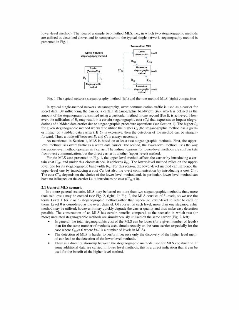
lower-level method). The idea of a simple two-method MLS, i.e., in which two steganographic methods
are utilised as described above, and its comparison to the typical single network steganography method is
presented in Fig. 1.
Fig. 1 The typical network steganography method (left) and the two-method MLS (right) comparison
In typical single-method network steganography, overt communication traffic is used as a carrier for
secret data. By influencing the carrier, a certain steganographic bandwidth (BS), which is defined as the
amount of the steganogram transmitted using a particular method in one second ([b/s]), is achieved. How-
ever, the utilisation of BS may result in a certain steganographic cost (CS) that expresses an impact (degra-
dation) of a hidden data carrier due to steganographic procedure operations (see Section 1). The higher BS
for given steganographic method we want to utilise the higher CS (the steganographic method has a great-
er impact on a hidden data carrier). If CS is excessive, then the detection of the method can be straight-
forward. Thus, a trade-off between BS and CS is always necessary.
As mentioned in Section 1, MLS is based on at least two steganographic methods. First, the upper-
level method uses overt traffic as a secret data carrier. The second, the lower-level method, uses the way
the upper-level method operates as a carrier. The indirect carriers for lower-level methods are still packets
from overt communication, but the direct carrier is another (upper-level) method.
For the MLS case presented in Fig. 1, the upper-level method affects the carrier by introducing a cer-
tain cost CSU, and under this circumstance, it achieves BSU. The lower-level method relies on the upper-
level one for its steganographic bandwidth BSL. For this reason, the lower-level method can influence the
upper-level one by introducing a cost CSL but also the overt communication by introducing a cost C’SL.
The cost C’SL depends on the choice of the lower-level method and, in particular, lower-level method can
have no influence on the carrier i.e. it introduces no cost (C’SL ≈ 0).
2.1 General MLS scenario In a more general scenario, MLS may be based on more than two steganographic methods; thus, more
than two levels may be created (see Fig. 2, right). In Fig. 2, the MLS consists of 3 levels, so we use the
terms Level 1 (or 2 or 3) steganographic method rather than upper- or lower-level to refer to each of
them. Level 0 is considered as the overt channel. Of course, on each level, more than one steganographic
method may be utilised; however, it may quickly degrade the carrier quality and thus make easy detection
possible. The construction of an MLS has certain benefits compared to the scenario in which two (or
more) unrelated steganographic methods are simultaneously utilised on the same carrier (Fig. 2, left):
• In general, the total steganographic cost of the MLS can be lower (for a given number of levels)
than for the same number of methods used simultaneously on the same carrier (especially for the
case where CSk0 ≈ 0 where k>1 is a number of levels in MLS).
• The detection of MLS is harder to perform because only the discovery of the higher level meth-
od can lead to the detection of the lower level methods.
• There is a direct relationship between the steganographic methods used for MLS construction. If
some additional data are carried in lower level methods, this is a direct indication that it can be
used for the benefit of the higher level method.
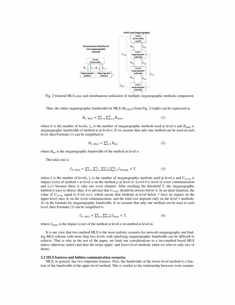
Fig. 2 General MLS case and simultaneous utilisation of multiple steganographic methods comparison
Thus, the entire steganographic bandwidth for MLS (BS-MLS) from Fig. 2 (right) can be expressed as
������ = ∑ ∑ �����
��� , (1)
where � is the number of levels, �� is the number of steganographic methods used at level n and ��� is
steganographic bandwidth of method m at level n. If we assume that only one method can be used at each
level, then Formula (1) can be simplified to
������ = ∑ ������ , (2)
where ��� is the steganographic bandwidth of the method at level n.
The total cost is
������ = ∑ ∑ ∑ ∑ ��������
�� ��
��� < ��
�� , (3)
where k is the number of levels, ln is the number of steganographic methods used at level n and CSnomp is
impact (cost) of method o at level n on the method p at level m. Level 0 is level of overt communication
and l0=1 because there is only one overt channel. After reaching the threshold T, the steganographic
method is easy to detect; thus, it is advised that CS-MLS should be always below it. In an ideal situation, the
value of CSnomp equal to 0 for n>1, which means that methods at level below 1 have no impact on the
upper-level ones or on the overt communication, and the total cost depends only on the level 1 methods.
As in the formula for steganographic bandwidth, if we assume that only one method can be used at each
level, then Formula (3) can be simplified to
������ = ∑ ∑ ��� < ��� ��
��� , (4)
where ��� is the impact (cost) of the method at level n on method at level m.
It is our view that two-method MLS is the most realistic scenario for network steganography and find-
ing MLS scheme with more than two levels with satisfying steganographic bandwidth can be difficult to
achieve. That is why in the rest of the paper, we limit our considerations to a two-method based MLS
unless otherwise stated (and thus the terms upper- and lower-level methods when we refer to only two of
them).
2.2 MLS features and hidden communication scenarios MLS, in general, has two important features. First, the bandwidth of the lower-level method is a frac-
tion of the bandwidth of the upper-level method. This is similar to the relationship between overt commu-
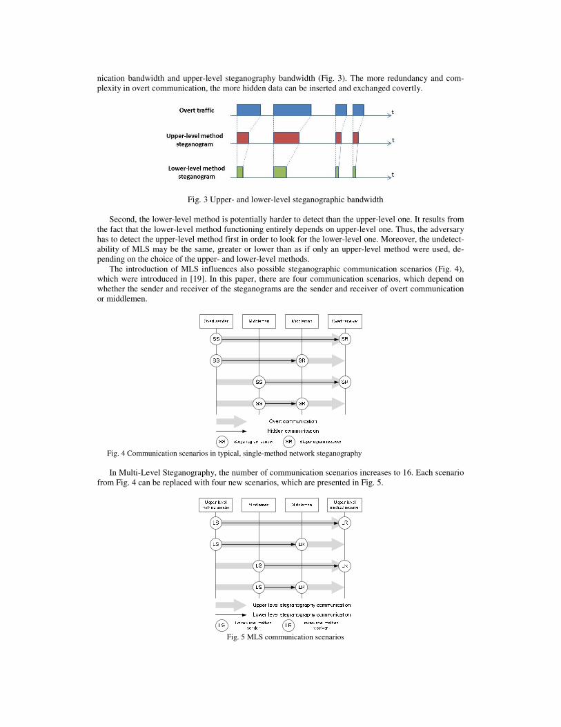
nication bandwidth and upper-level steganography bandwidth (Fig. 3). The more redundancy and com-
plexity in overt communication, the more hidden data can be inserted and exchanged covertly.
Fig. 3 Upper- and lower-level steganographic bandwidth
Second, the lower-level method is potentially harder to detect than the upper-level one. It results from
the fact that the lower-level method functioning entirely depends on upper-level one. Thus, the adversary
has to detect the upper-level method first in order to look for the lower-level one. Moreover, the undetect-
ability of MLS may be the same, greater or lower than as if only an upper-level method were used, de-
pending on the choice of the upper- and lower-level methods.
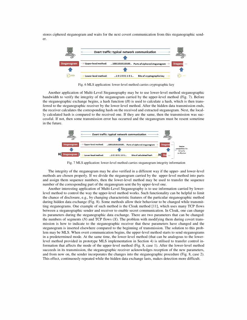
The introduction of MLS influences also possible steganographic communication scenarios (Fig. 4),
which were introduced in [19]. In this paper, there are four communication scenarios, which depend on
whether the sender and receiver of the steganograms are the sender and receiver of overt communication
or middlemen.
Fig. 4 Communication scenarios in typical, single-method network steganography
In Multi-Level Steganography, the number of communication scenarios increases to 16. Each scenario
from Fig. 4 can be replaced with four new scenarios, which are presented in Fig. 5.
Fig. 5 MLS communication scenarios

The upper-level method steganogram sender and receiver in Fig. 5 are the steganography sender and
steganography receiver, in Fig. 4, respectively. The middlemen in Fig. 4 are network devices that are
placed between the sender and receiver of the upper-level steganographic method. They have to be aware
of the upper-level method in order to use it to create the lower-level method.
Each known steganographic method can presumably be used as an upper-level method. The main
problem is to find a suitable lower-level method that will cooperate with the upper-level one. If we con-
sider, for example, methods like LACK [13], RSTEG [12] or SCTP hybrid method [3] as an upper-level
method (which modify the packet payload to insert a steganogram), then the lower-level method can hide
bits in the number of packets that the steganogram of the upper-level method sends in established time
periods. For example, if a packet with the steganogram is sent during a one-second period – it means
binary “1”, else (i.e. if packet is sent later) – it means binary “0”.
3. MLS Applications
Multi-Level Steganography can be utilised to achieve various aims – it all depends on how it will be
used. Here we present several of the most interesting MLS applications, in our opinion. The benefits of
MLS for hidden data exchange are summarised in Table I.
Table I – MLS benefits and possible applications
MLS benefit Described MLS application
Increased steganographic band-
width for user data
Using two or more steganographic methods increases
the total steganographic bandwidth achieved for user
data compared with a single steganographic method.
Increased undetectability An upper-level method controlled by information car-
ried by the lower-level method (Sec. 3.1). Steganogram transmission relia-
bility
Lower-level method carrying information for ste-
ganogram integrity verification (Sec. 3.1). Harder steganogram extraction
and analysis
1. Cryptographic key carried by lower-level method
and upper-level method steganogram ciphered
(Sec. 3.1).
2. Parts of the steganogram sent using the upper-level
and others by the lower-level method (Sec. 3.3).
3. Steganogram carried only by the lower-level
method; upper-level steganogram only for masking
(Sec. 3.2). Steganographic cost unchanged In best-case scenario, depends on the upper- and lower-
level methods used, but can be the same as for utilisa-
tion of the upper-level method alone.
Let us consider the abovementioned MLS applications based on where the steganogram is inserted. There
are three possible cases:
• Steganogram is carried only by upper-level method
• Steganogram is carried only by lower-level method
• Steganogram is carried by both upper- and lower-level methods
The rest of this section describes these cases in detail.
3.1 Only upper-level method carries steganogram
If steganogram is only carried by the upper-level steganographic method, then the lower-level method
may be utilised for special purposes. For example, it may carry a cryptographic key that was used to ci-
pher the steganogram sent by the upper-level method (Fig. 6). Such an MLS application is possible only
for steganographic communication scenarios in which the upper- and lower-level hidden communication
paths are the same (compare Fig. 4 and 5). It is assumed that the steganogram was ciphered before initiat-
ing the steganographic exchange to avoid any unnecessary delays. When overt traffic is sent, so are the
parts of the ciphered steganogram (upper-level method) and bits of the cryptographic key (lower-level
method). After all bits of the ciphered steganogram and cryptographic key are successfully received, the
steganographic receiver is ready to decipher the steganogram. If the hidden communication, for some
reason, did not last long enough to send the whole cryptographic key, then the steganographic receiver
stores ciphered steganogram and waits for the next covert communication from this steganographic send-
er.
Fig. 6 MLS application: lower-level method carries cryptographic key
Another application of Multi-Level Steganography may be to use lower-level method steganographic
bandwidth to verify the integrity of the steganogram carried by the upper-level method (Fig. 7). Before
the steganographic exchange begins, a hash function (H) is used to calculate a hash, which is then trans-
ferred to the steganographic receiver by the lower-level method. After the hidden data transmission ends,
the receiver calculates the corresponding hash on the received and extracted steganogram. Next, the local-
ly calculated hash is compared to the received one. If they are the same, then the transmission was suc-
cessful. If not, then some transmission error has occurred and the steganogram must be resent sometime
in the future.
Fig. 7 MLS application: lower-level method carries steganogram integrity information
The integrity of the steganogram may be also verified in a different way if the upper- and lower-level
methods are chosen properly. If we divide the steganogram carried by the upper-level method into parts
and assign them sequence numbers, then the lower-level method may be used to transfer the sequence
number of the corresponding part of the steganogram sent the by upper-level one.
Another interesting application of Multi-Level Steganography is to use information carried by lower-
level method to control the way the upper-level method works. Such functionality can be helpful to limit
the chance of disclosure, e.g., by changing characteristic features of the particular steganographic method
during hidden data exchange (Fig. 8). Some methods allow their behaviour to be changed while transmit-
ting steganograms. One example of such method is the Cloak method [11], which uses many TCP flows
between a steganographic sender and receiver to enable secret communication. In Cloak, one can change
its parameters during the steganographic data exchange. There are two parameters that can be changed:
the numbers of segments (N) and TCP flows (X). The problem with modifying them during covert trans-
mission is how to indicate to the steganographic receiver that these parameters have changed and the
steganogram is inserted elsewhere compared to the beginning of transmission. The solution to this prob-
lem may be MLS. When overt communication begins, the upper-level method starts to send steganograms
in a predetermined mode. At the same time, the lower-level method (that can be analogous to the lower-
level method provided in prototype MLS implementation in Section 4) is utilised to transfer control in-
formation that affects the mode of the upper-level method (Fig. 8, case 1). After the lower-level method
succeeds in its transmission, the steganographic receiver acknowledges reception of the new parameters,
and from now on, the sender incorporates the changes into the steganographic procedure (Fig. 8, case 2).
This effect, continuously repeated while the hidden data exchange lasts, makes detection more difficult.
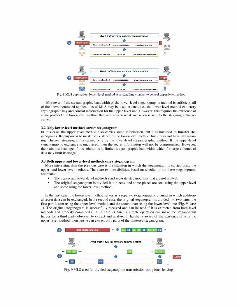
Fig. 8 MLS application: lower-level method as a signalling channel to control upper-level method
Moreover, if the steganographic bandwidth of the lower-level steganographic method is sufficient, all
of the abovementioned applications of MLS may be used at once, i.e., the lower-level method can carry
cryptographic key and control information for the upper-level one. However, this requires the existence of
some protocol for lower-level method that will govern what and when is sent to the steganographic re-
ceiver.
3.2 Only lower-level method carries steganogram In this case, the upper-level method also carries some information, but it is not used to transfer ste-
ganograms. Its purpose is to mask the existence of the lower-level method, but it does not have any mean-
ing. The real steganogram is carried only by the lower-level steganographic method. If the upper-level
steganographic exchange is uncovered, then the secret information will not be compromised. However,
the main disadvantage of this solution is its limited steganographic bandwidth, which for large volumes of
data may limit its usage.
3.3 Both upper- and lower-level methods carry steganogram More interesting than the previous case is the situation in which the steganogram is carried using the
upper- and lower-level methods. There are two possibilities, based on whether or not these steganograms
are related:
• The upper- and lower-level methods send separate steganograms that are not related,
• The original steganogram is divided into pieces, and some pieces are sent using the upper-level
and some using the lower-level method.
In the first case, the lower-level method serves as a separate steganographic channel in which addition-
al secret data can be exchanged. In the second case, the original steganogram is divided into two parts; the
first part is sent using the upper-level method and the second part using the lower-level one (Fig. 9, case
1). The original steganogram is successfully received and can be read if it is extracted from both level
methods and properly combined (Fig. 9, case 2). Such a simple operation can make the steganogram
harder for a third party observer to extract and analyse. If he/she is aware of the existence of only the
upper-layer method, then he/she can extract only parts of the shattered steganogram.
Fig. 9 MLS used for divided steganogram transmission using inter-leaving
4. MLS Prototype and Experimental Results
For MLS prototype development two steganographic methods were used. As an upper-layer method,
LACK [13] was utilised. This method is intended for a broad class of multimedia, real-time applications
like IP telephony. In IP telephony, conversation is based on exchanging RTP (Real-Time Transport Pro-
tocol) streams between calling parties. Each of the RTP is uniquely identified with a sequence number.
LACK utilises the fact that for usual multimedia communication protocols like RTP, excessively de-
layed packets are not used for the reconstruction of transmitted data at the receiver, i.e., the packets are
considered useless and discarded. The idea of LACK is as follows. At the transmitter, some selected au-
dio packets are intentionally delayed before transmitting. If the delay of such packets at the receiver is
considered excessive, the packets are discarded by a receiver that is not aware of the steganographic pro-
cedure. The payload of the intentionally delayed packets is used to transmit secret information to receiv-
ers aware of the procedure, so no extra packets are generated. For unaware receivers, the hidden data are
“invisible”.
A lower-level method is based on proper RTP sequence number matching. It modifies the choice of the
RTP packet (its sequence number) used for LACK purposes depending on the steganogram bits to be
sent.
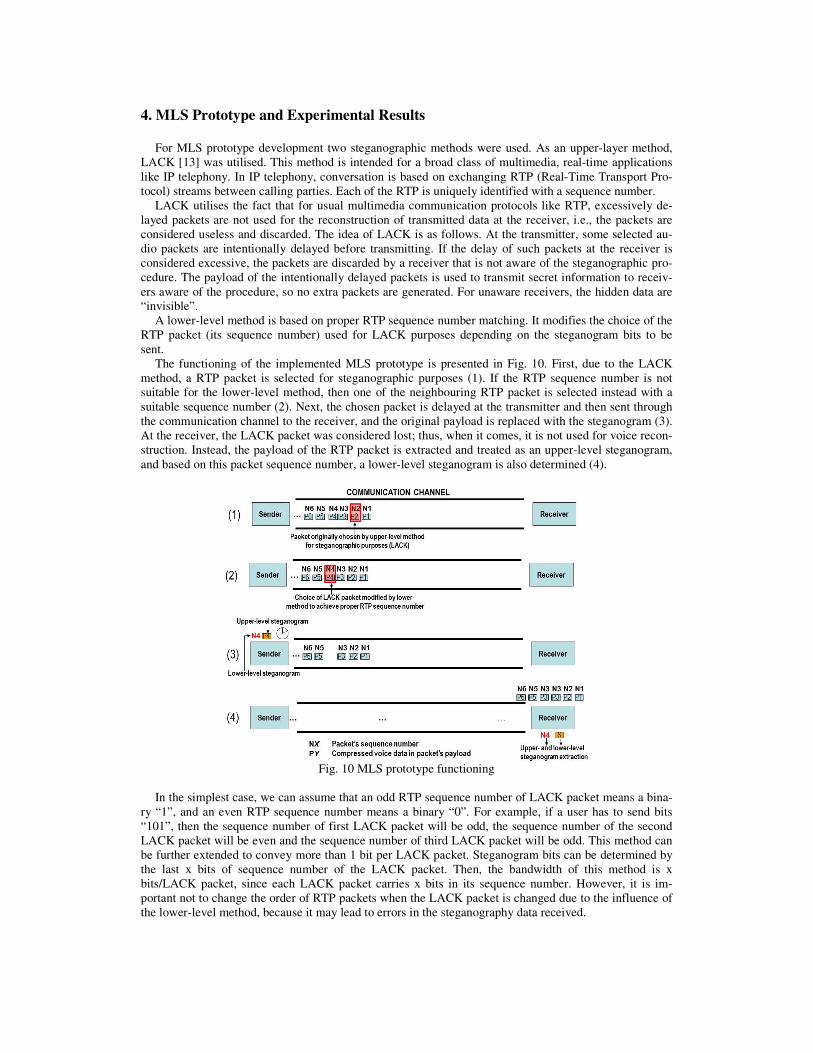
The functioning of the implemented MLS prototype is presented in Fig. 10. First, due to the LACK
method, a RTP packet is selected for steganographic purposes (1). If the RTP sequence number is not
suitable for the lower-level method, then one of the neighbouring RTP packet is selected instead with a
suitable sequence number (2). Next, the chosen packet is delayed at the transmitter and then sent through
the communication channel to the receiver, and the original payload is replaced with the steganogram (3).
At the receiver, the LACK packet was considered lost; thus, when it comes, it is not used for voice recon-
struction. Instead, the payload of the RTP packet is extracted and treated as an upper-level steganogram,
and based on this packet sequence number, a lower-level steganogram is also determined (4).
Fig. 10 MLS prototype functioning
In the simplest case, we can assume that an odd RTP sequence number of LACK packet means a bina-
ry “1”, and an even RTP sequence number means a binary “0”. For example, if a user has to send bits
“101”, then the sequence number of first LACK packet will be odd, the sequence number of the second
LACK packet will be even and the sequence number of third LACK packet will be odd. This method can
be further extended to convey more than 1 bit per LACK packet. Steganogram bits can be determined by
the last x bits of sequence number of the LACK packet. Then, the bandwidth of this method is x
bits/LACK packet, since each LACK packet carries x bits in its sequence number. However, it is im-
portant not to change the order of RTP packets when the LACK packet is changed due to the influence of
the lower-level method, because it may lead to errors in the steganography data received.
4.1. MLS Prototype Implementation
Implementation of MLS prototype was based on MjSip [14] project. It is a Java implementation of
VoIP softphone based on a SIP (Session Initiation Protocol) signalling protocol. Only the user agent ap-
plication was utilised; the SIP server was omitted because it does not affect the results of experiments (the
RTP streams are exchanged directly between end users, without using the SIP server). In the SIP User
Agent application, a simple PLC (Packet Loss Concealment) method was implemented, as softphones
usually have some way to deal with packets losses. PLC mechanisms are used to limit quality degradation
due to packet loss – in the simplest scenario, these insert a repetition of the last received packet to substi-
tute for a missing one [8]. This PLC method was added to the SIP User Agent application.
The implementation of the upper-level method, LACK, was straightforward. For each RTP packet cho-
sen for LACK purposes, the payload consists of two parts: steganogram and hash. The hash is computed
for the steganogram carried in that packet using the MD5 (Message Digest 5) hash function. It allows the
receiver to distinguish LACK packets from normally transmitted non-steganographic ones.
Two parameters of the LACK method were affected: the probability that a packet is used for LACK
purposes (pLACK) and the minimum delay of LACK packets. For each RTP packet, a pseudo-random num-
ber between 0 and 1 was generated, and it was tested whether the number is smaller than established
probability of sending a LACK packet. If this was the case, then the packet was chosen for steganograph-
ic purposes.
The implementation of the lower-level method required (if necessary) modification of the upper-level
choice of LACK packet. If the upper-level method selected an RTP packet for LACK purposes whose
sequence number satisfied the needs of the lower-level method, i.e., the steganogram bits to be sent, the
packet is not changed. Otherwise, an RTP packet with the proper RTP sequence number is selected. The
lower-level method tries to select RTP packets as close as possible to the packets originally selected by
the upper-level method.
For example, let us assume that the lower-level method to carry steganogram utilizes two least signifi-
cant bits of each RTP packet’s (selected by upper-level method) sequence number. In that case, if the bits
of the lower-level steganogram to be sent are “10” and the sequence number chosen for LACK purposes
is odd e.g. it is 51 (110011), then lower-level method influence the choice by changing it to the neigh-
bouring RTP packet with even sequence number e.g. 54 (110110). Then this RTP packet’s payload will
be replaced with the upper-level steganogram.
The main issue was not to change the order of RTP packets because of a change in the LACK packets
imposed by the lower-level method. The problem was solved by marking only one packet for LACK
purposes at any given moment. If more than one packet was chosen to be marked for LACK purposes at
the same time, then only one was marked. However, it was noted that additional packets must be sent as
LACK packets. For example, if the RTP sequence number of the packet chosen by upper-level method is
51 but was changed to 54 by the lower-level method, and, simultaneously, sequence number 53 was the
next chosen by upper-level method, then the packet with sequence number 53 is not considered as a
LACK packet (in order not to break the rule “one packet for LACK purposes at any given moment”).
After sending the LACK packet (with original sequence number 51), additional packet will be chosen for
LACK purposes.
One parameter of the lower-level method was subject to configuration, which was the number of low-
er-level bits of steganogram that are sent with each LACK packet. This parameter must be set the same
for both the sender and receiver of the lower-level steganogram.
4.2. Experiment Methodology and Results
The experimental setup is presented in Fig. 11. The environment for experiment was a LAN network,
so no packets were lost or excessively delayed except intentionally, which permitted us to evaluate the
sole impact of LACK and MLS on voice quality, without any network-related or endpoint-related inter-
ferences.

Fig. 11 MLS experimental setup
The conversation was recorded in advance and encoded with G.711 (each RTP packet carries 20 ms of
voice using 160 bytes; the packet flow rate is 50 packets per second) and then saved as an input .wav file.
The duration of the conversation was set to 9 minutes, as it is experimentally verified that the average call
duration for IP telephony is in the range 7-11 minutes [6]. Then, parts of the .wav file were inserted into
the payloads of consecutive RTP packets. Next, the RTP stream was influenced by the chosen ste-
ganographic methods:
• Only LACK, where MLS is not used – this case will be treated as a reference for MLS.
• MLS that transfers 1 bit of the lower-level method steganogram in a single LACK packet (MLS-
1).
• MLS that transfers 2 bits of the lower-level method steganogram in single LACK packet (MLS-
2).
• MLS that transfers 3 bits of the lower-level method steganogram in a single LACK packet
(MLS-3).
In the next step, the RTP stream was sent to the receiver, which reconstructed the voice conversation
and saved it to the output .wav file. Then, the parts of about 30 s length of original (input) and degraded
(output) .wav files were compared using the PESQ method [9], and the MOS-LQO (Mean Opinion Score
- Listening Quality Objective) value was obtained. Then the average MOS-LQO was calculated. By per-
forming experiments in a strictly controlled environment with no losses and excessive delays, we were
able to assess the real influence of MLS on the conversation quality. For each steganographic method
mentioned above, the experiment was repeated 10 times, and the average results are presented.
We decided to set the probability of selecting an RTP packet for steganographic (LACK) purposes by
upper-level method to 0.032 because it resulted in MOS-LQO value around 3.6 which is regarded as a
quality compared with that achieved in PSTN networks. It also means that the cost of the upper level
method is CSU ≈ 0.7 in MOS scale (see Fig. 1), because the quality of the G.711-based connection without
LACK is about 4.3.
The probability of selecting an RTP packet for steganographic purposes by upper-level method was
set the same for all experiments, but it was not always achieved. The actual, real value of the RTP packets
selected for LACK purposes could be different because of process of generation random numbers.
For presented experimental setup we measured steganographic bandwidth of upper- and lower-level
methods (BSU, BSL) and the corresponding costs introduced (CSU, CSL). Obtained experimental results are
presented in Table II and Fig. 12 and 13.
Table II Experimental results
LACK MLS-1 MLS-2 MLS-3 Average CI (95%) Average CI (95%) Average CI (95%) Average CI (95%)
MOS-LQO 3.609 0.018 3.617 0.025 3.626 0.015 3.625 0.019
CSU [MOS] ≈ 0.7 ≈ 0.7 ≈ 0.7 ≈ 0.7
CSL [MOS] N/A ≈ 0 ≈ 0 ≈ 0
pLACK 0.0317 0.0008 0.0323 0.0017 0.0316 0.0007 0.0315 0.0006
BSU [bit/s] 1827.41 48.39 1837.87 44.13 1822.08 39.20 1812.48 36.74
BSL [bit/s] 0.00 0.00 1.60 0.04 3.16 0.07 4.72 0.10
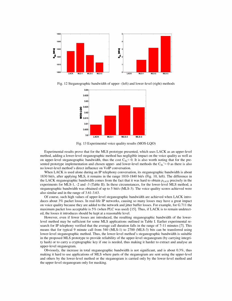
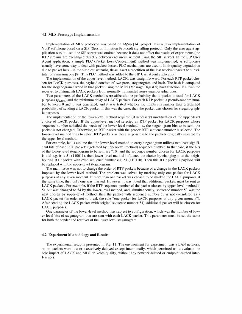
Fig. 12 Steganographic bandwidth of upper- (left) and lower-level (right) methods
Fig. 13 Experimental voice quality results (MOS-LQO)
Experimental results prove that for the MLS prototype presented, which uses LACK as an upper-level
method, adding a lower-level steganographic method has negligible impact on the voice quality as well as
on upper-level steganographic bandwidth, thus the cost CSL≈ 0. It is also worth noting that for the pre-
sented prototype implementation and chosen upper- and lower-level methods the CSL’≈ 0 as there is also
no lower-level method’s direct influence on VoIP conversation.
When LACK is used alone during an IP telephony conversation, its steganographic bandwidth is about
1830 bit/s, after applying MLS, it remains in the range 1810-1840 bit/s (Fig. 10, left). The difference in
the LACK steganographic bandwidth comes from the fact that it was hard to obtain pLACK precisely in the
experiments for MLS-1, -2 and -3 (Table II). In these circumstances, for the lower-level MLS method, a
steganographic bandwidth was obtained of up to 5 bit/s (MLS-3). The voice quality scores achieved were
also similar and in the range of 3.61-3.63.
Of course, such high values of upper-level steganographic bandwidth are achieved when LACK intro-
duces about 3% packet losses. In real-life IP networks, causing so many losses may have a great impact
on voice quality because they are added to the network and jitter buffer losses. For example, for G.711 the
maximum packet loss acceptable is 5% (when PLC was used) [15]. Thus, if LACK is to remain undetect-
ed, the losses it introduces should be kept at a reasonable level.
However, even if fewer losses are introduced, the resulting steganographic bandwidth of the lower-
level method may be sufficient for some MLS applications outlined in Table I. Earlier experimental re-
search for IP telephony verified that the average call duration falls in the range of 7-11 minutes [7]. This
means that for typical 9 minute call from 540 (MLS-1) to 2700 (MLS-3) bits can be transferred using
lower-level steganographic method. Thus, the lower-level method’s steganographic bandwidth is suitable
in the proposed MLS prototype to provide reliability of the upper-level steganogram (by carrying integri-
ty hash) or to carry a cryptographic key if one is needed, thus making it harder to extract and analyse an
upper-level steganogram.
Obviously, the increase in total steganographic bandwidth is not significant, and is about 0.3%, thus
making it hard to use applications of MLS where parts of the steganogram are sent using the upper-level
and others by the lower-level method or the steganogram is carried only by the lower-level method and
the upper-level steganogram only for masking.
LACK MLS-1 MLS-2 MLS-31800
1810
1820
1830
1840
1850
BB BBSS SS
UU UU [
bit
/s]
[b
it/s
] [
bit
/s]
[b
it/s
]
LACK MLS-1 MLS-2 MLS-30
1
2
3
4
5
BB BBSS SS
LL LL [
bit
/s]
[b
it/s
] [
bit
/s]
[b
it/s
]
LACK MLS-1 MLS-2 MLS-33.6
3.605
3.61
3.615
3.62
3.625
3.63
3.635
3.64
MO
S-L
QO
MO
S-L
QO
MO
S-L
QO
MO
S-L
QO
However, it must be noted that for the MLS prototype developed, the steganographic cost is unchanged
when compared to the situation when only LACK is used. To conclude, what MLS applications, out of
those mentioned in Table I, may be applied in a particular case depends on the choice of the upper- and
lower-level methods – different MLSs may be more suitable for different MLS applications.
5. Conclusions and future work
In this paper, a new concept for performing hidden communication, called Multi-Level Steganography
for network steganography, was presented. MLS consists of at least two steganographic methods are
utilised simultaneously, in such a way that one method (called the upper-level) serves as a carrier for the
second one (called the lower-level). Such relationship between two (or more) information hiding solu-
tions has several potential benefits, e.g., it may provide increased steganographic bandwidth or increase
undetectability. It can also be utilised for ensuring the reliability of steganogram transmission reliability
or making steganogram extraction and analysis harder to perform.
The nature of network steganography environment i.e. binding of the overt communication process
with steganographic method allows to pinpoint some useful MLS applications that can really improve
hidden communications in telecommunication networks that were not considered before.
The MLS prototype was developed to prove its concept. It was implemented in an IP telephony envi-
ronment. It was based on a previously introduced LACK solution as an upper-level method and selecting
odd/even RTP sequence numbers for LACK packets as a lower-level method. For this prototype, the
steganographic cost was unchanged compared to the situation when only the upper-level method was
used.
Experimental results were obtained that proved that some of the described above MLS applications can
be easily applied. It turned out that the lower-level method’s steganographic bandwidth is suitable to
provide reliability of the upper-level steganogram (by carrying integrity hash) or to carry a cryptographic
key that secret data was encrypted with, thus making it harder to extract and analyse an upper-level ste-
ganogram. It can be also utilised to increase the upper-level method undetectability by utilizing the lower-
level method’s steganographic bandwidth to exchange control information between the covert parties that
will influence the upper-level one functioning.
In general, for MLS, the most important is the choice of upper- and lower-level methods. In an ideal
situation, the steganographic cost of the lower-level method should be equal to 0 or very small when
compared with the steganographic cost of the upper-level one. Moreover, the higher the steganographic
bandwidth of the lower-level method, the more the described MLS applications can be applied.
Our future work will be focused on developing more efficient MLS schemes because the benefits for
such constructions of hidden data exchange are considerable and they solve some open challenges related
to network steganography (providing steganogram reliability and cryptographic key exchange). Future
work will also include analysing MLS detection options.
ACKNOWLEDGMENT This work was supported by the Polish Ministry of Science and Higher Education and Polish National
Science Centre under grants: 0349/IP2/2011/71 and 2011/01/D/ST7/05054.
References
1. Al-Najjar AJ. (2008) The Decoy: Multi-Level Digital Multimedia Steganography Model. In Proc. of 12th
WSEAS International Conference on Communications, Heraklion, Greece, July 23-25, 2008
2. Burnett, S., Feamster, N., Vempala, S., Chipping Away at Censorship Firewalls with User-Generated Con-
tent. USENIX Security Symposium 2010: 463-468
3. Frączek, W., Mazurczyk, W., Szczypiorski, K. (2010) Stream Control Transmission Protocol Steganogra-
phy. In Proc. of Second International Workshop on Network Steganography (IWNS 2010) co-located with
The 2010 International Conference on Multimedia Information Networking and Security (MINES 2010),
Nanjing, China, November 4-6, 2010
4. Frączek, W., Mazurczyk, W., Szczypiorski, K. (2011) Multi-Level Steganography Applied to Networks. In
Proc. of: Third International Workshop on Network Steganography (IWNS 2011) co-located with The 2011
International Conference on Telecommunication Systems, Modeling and Analysis (ICTSM2011), Prague,
Czech Republic, 27-28 May 2011
5. Goodin, D. , Duqu spawned by ’well-funded team of competent coders’ - world’s first known modular
rootkit does steganography, too, The Register, November 2011,
http://www.theregister.co.uk/2011/11/09/duqu_analysis/
6. Guha S., Daswani N., Jain R. (2006) An experimental study of the skype peer-to-peer VoIP system. In
Proc. Of Sixth International Workshop on Peer-to-Peer Systems (IPTPS), February 2006
7. Guha, S., Daswani, N., Jain, R.: An experimental study of the Skype peer-to-peer VoIP system. Sixth Inter-
national Workshop on Peer-to-Peer Systems (IPTPS), February 2006
8. ITU-T Recommendation: G.711 (1988), Pulse code modulation (PCM) of voice frequencies. International
Telecommunications Union, Geneva, Switzerland
9. ITU-T, Recommendation. P.862 (2001) Perceptual evaluation of speech quality (PESQ): An objective
method for end-to-end speech quality assessment of narrow-band telephone networks and speech codecs.
International Telecommunications Union, Geneva, Switzerland
10. Jankowski, B., Mazurczyk, W., Szczypiorski, K. (2010) Information Hiding Using Improper Frame Pad-
ding, In Proc. of 14th International Telecommunications Network Strategy and Planning Symposium (Net-
works 2010), Warsaw, Poland, ISBN 978-1-4244-6703-7, 27-30 September 2010, pp. 77-82
11. Luo, X., Chan, E.W.W, Chang, R.K.C (2007) Cloak: A Ten-fold Way for Reliable Covert Communica-
tions, In Proc. of 12th European Symposium on Research in Computer Security (ESORICS), September
2007
12. Mazurczyk, W., Smolarczyk, M., Szczypiorski, K. (2009) Retransmission steganography and its detection.
Soft Computing, Journal no. 500 Springer, ISSN: 1432-7643 (print version), ISSN: 1433-7479 (electronic
version), November 2009
13. Mazurczyk, W., Szczypiorski, K. (2008) Steganography of VoIP Streams. In: R. Meersman and Z. Tari
(Eds.): OTM 2008, Part II - Lecture Notes in Computer Science (LNCS) 5332, Springer-Verlag Berlin Hei-
delberg, Proc. of The 3rd International Symposium on Information Security (IS'08), Monterrey, Mexico,
November 10-11, 2008, pp. 1001-1018
14. MjSip Project website: http://www.mjsip.org/
15. Na, S., Yoo, S. (2002) Allowable Propagation Delay for VoIP Calls of Acceptable Quality. In Proc. of First
International Workshop, AISA 2002, Seoul, Korea, LNCS Vol. 2402/2002, August 2002, pp. 469-480,
Springer Berlin / Heidelberg
16. Petitcolas F, Anderson R, Kuhn M (1999) Information hiding—a survey IEEE. Special Issue on Protection
of Multimedia Content, July 1999
17. Rescorla, E. (1999) Diffie-Hellman Key Agreement Method. IETF Request for Comments: 2631, June
1999
18. Virus Bulletin, Alureon trojan uses steganography to receive commands, September 2011,
URL:http://www.virusbtn.com/news/2011/09_26.xml.
19. Zander, S., Armitage, G., Branch, P. (2007) A Survey of Covert Channels and Countermeasures in Com-
puter Network Protocols, IEEE Communications Surveys & Tutorials, 3rd Quarter 2007, Volume: 9, Issue:
3, pp. 44-57, ISSN: 1553-877X
Related Documents