Multi Internal Nucleophile Ring Expansion Reactions Dominic Eamon Spurling MSc by Research University of York Department of Chemistry August 2020

Welcome message from author
This document is posted to help you gain knowledge. Please leave a comment to let me know what you think about it! Share it to your friends and learn new things together.
Transcript

Multi Internal Nucleophile Ring
Expansion Reactions
Dominic Eamon Spurling
MSc by Research
University of York
Department of Chemistry
August 2020

ii
Abstract
This thesis describes a novel method for the cyclisation of linear precursors possessing
multiple internal nucleophiles, via multi internal nucleophile ring expansion (multi-INRE)
cascade reactions to yield novel heterocyclic-macrocyclic lactones.
Section 2.1 describes the design of proposed novel linear multi-INRE precursor A and
associated synthetic strategies. Section 2.2 presents the multistep synthesis route to linear
multi-INRE precursor A which, after considerable optimisation, was achieved on a three-
gram scale with an overall yield of 50%. Section 2.3 details the first reported multi-INRE
reaction, with the synthesis of heterocyclic-macrocyclic lactone B. Section 2.3 also
comments on the atroposelectivity of the multi-INRE reaction A → B with a kinetic model
proposed to explain the selectivity. Section 3.3 details the synthesis and subsequent
cyclisation of two aliphatic linear precursors (C) via multi-INRE reactions. In this section,
two novel aliphatic linear precursors possessing two internal amine nucleophiles (C) and
their respective multi-INRE heterocyclic-macrocyclic lactone products (D) are synthesised.
Section 3.4 details the screening of multi-INRE reaction A → B, culminating in the
discovery of conditions that enable a yield of 73% for the initial multi-INRE. Finally, chapter
four details the design of three other potential linear precursors containing two internal
nucleophiles and describes the progress made towards the synthesis of each (E, F and G).
iii
Contents
Abstract ii
Contents iii
List of Tables v
List of Figures vi
List of Schemes vii
Acknowledgements xi
Authors Declaration xii
Chapter One: Introduction 1
1.1 Medium-sized Rings and Macrocycles 1
1.2 Synthesis of Medium-Sized Rings and Macrocycles via Sequential Ring
Expansion Reactions 3
1.2.1 Transesterification/Transamidation 3
1.2.2 Radical Cascade Reactions 6
1.2.3 Fragmentation Reactions 8
1.2.4 Pericyclic Reactions 10
1.2.5 Ring Expansion Metathesis Polymerisation 14
1.2.6 Rhodium-Catalysed Ring Expansion 17
1.2.7 Successive Ring Expansion 20
1.2.8 Internal Nucleophile Ring Expansion 23
1.3 Project Aims 27
Chapter Two: Initial Multi Internal Nucleophile Ring Expansion Precursor Design
and Synthesis. 30
2.1 Designing an Initial Precursor 30
2.2 Building Initial Multi-INRE Precursor 162 32
2.3 Initial Multi-INRE Reaction 38
2.4 Summary 42
Chapter Three: Multi-INRE Screening and Aliphatic Precursor Synthesis 43
3.1 Initial Screening of multi-INRE reaction 162 → 164 43
3.2 Theorised INRE Reaction Intermediate 45
3.3 Exploration of Aliphatic Precursors 48
3.4 Screening of multi-INRE reaction 162 → 164 With Internal Standard 53
3.5 Summary 58

iv
Chapter Four: Further Exploration of Scope 59
4.1 Synthetic Targets 59
4.2 Synthesis of a Precursor with Phenylamine Terminal Nucleophile (207) 60
4.3 Work Towards a Precursor with Phenylamine Internal Nucleophile (210) 62
4.4 Work Towards a Mono-Aryl Precursor (211) 65
4.5 Summary 68
Chapter Five: Future Work 70
5.1 Short-Term Objectives 70
5.2 Long-Term Objectives 72
Chapter Six: Conclusion 76
Chapter Seven: Experimental 78
4.1 General Experimental 78
4.2 List of Experimental Procedures and Characterisation 79
Abbreviations 126
References 130

v
List of Tables
Table 1: Lithiation-trapping optimisation for amine 174 synthesis.................................. 33
Table 2: Initial screening conditions for reaction 162 → 164 and their respective isolated
yields. a Performed on 300 mg scale...................................................................................... 43
Table 3: Screening conditions using internal standard and their respective yield. b Solvent
dried out................................................................................................................................. 55
vi
List of Figures
Figure 1: Medium-sized rings and macrocycles in relevant compounds. 1 (-)-ovatolide, 2
PI3Kα inhibitor, 3 NMR chiral shift reagent......................................................................... 1
Figure 2: Simple diagram showing the difficulty of end-to-end cyclisation using longer linear
precursors............................................................................................................................... 2
Figure 3: Natural products formed using zip reactions. Celacinnine 11, homaline 12, and
inandenin-12-one 13.............................................................................................................. 5
Figure 4: Model demonstrating function of the internal nucleophilic catalyst (green) in an
internal nucleophile ring expansion reaction......................................................................... 24
Figure 5: Hypothetical reaction coordinate of a generic INRE reaction...............................24
Figure 6: Hypothetical reaction coordinate of a general multi-INRE reaction..................... 28
Figure 7: 1H NMR Spectrum of multi-INRE product lactone 164........................................ 39
Figure 8: Possible diastereoisomers which could yield from the multi-INRE reaction........ 40
Figure 9: 13C NMR spectrum of macrocyclic lactone 164.................................................... 40
Figure 10: Single crystal XRD structure of macrocyclic lactone 164(i)............................... 41
Figure 11: Hypothetical reaction coordinate illustrating energy minimums with and without
formation of by-product 183. ................................................................................................ 46
Figure 12: 13C NMR spectra of biaryl lactone 164 (top), 13-membered aliphatic lactone 192
(middle), and 14-membered aliphatic lactone 203 (bottom)................................................ 53
Figure 13: 1H NMR spectrum of crude reaction mixture and internal standard 1,3,5-
trimethoxybenzene................................................................................................................. 54

vii
List of Schemes
Scheme 1: The first reported incident of a zip reaction using a simple cyclic amide........... 3
Scheme 2: A zip reaction forming a 53-membered macrocycle........................................... 4
Scheme 3: Corey and Nicolaou – transesterification ring expansion to make a 12-membered
ring......................................................................................................................................... 5
Scheme 4: J. P. Tam et al. – the use of transthioesterification to make large peptide
macrocycles (N-terminal cysteine in orange and C-terminal residues in green)................... 5
Scheme 5: Free radical ring expansion of 5-membered ring 18 into 6-membered ring 21... 6
Scheme 6: Cascade radical ring expansion followed by Grob fragmentation....................... 7
Scheme 7: Radical cascade for the conversion of four membered ring oxime 31 into 6 and 5
membered bicyclic oxime 34................................................................................................. 8
Scheme 8: Double ring expansion via Grob fragmentation.................................................. 9
Scheme 9: Grob fragmentation followed by oxidative expansion leading to a cascade ring
expansion............................................................................................................................... 9
Scheme 10: Oxidative fragmentation followed by a transesterification............................... 10
Scheme 11: Successive sigmatropic rearrangement using sulfur ylides to form an 11-
membered ring....................................................................................................................... 11
Scheme 12: Ring expansion via alkylation and sigmatropic rearrangement........................ 11
Scheme 13: Undesired side product formation in sulfur ylide sigmatropic
rearrangement........................................................................................................................ 12
Scheme 14: Consecutive aza-Cope sigmatropic rearrangement........................................... 13
Scheme 15: aza-Claisen rearrangements giving ring expanded macrocycles....................... 13
Scheme 16: Formation of macrocycles through iterative carbene cyclopropanation and
expansion............................................................................................................................... 14
Scheme 17: Formation of 18-membered macrocycle 100 through REMP........................... 15
Scheme 18: Catalytic cycle of successive REMP through polymerisation of norbornene
units........................................................................................................................................ 16
Scheme 19: Proposed catalytic cycle for Rh(I)-catalysed carbonylative carbocyclisation of
cyclopropene.......................................................................................................................... 18
Scheme 20: “Capture-collapse” directed carbonylative C-C ring expansion of
aminocyclopropane............................................................................................................... 19
Scheme 21: Lactone formation by rhodium‐catalyzed C−C bond cleavage of
cyclobutanone........................................................................................................................ 19

viii
Scheme 22: Successive ring expansion reactions with β-amino acid fragments.................. 20
Scheme 23: Successive ring expansion using simple lactams and β-amino acid
fragments............................................................................................................................... 21
Scheme 24: Successive ring expansion using simple lactams and β-hydroxy acid
fragments............................................................................................................................... 22
Scheme 25: Successive ring expansion with both hydroxy and amino acids....................... 23
Scheme 26: INRE with a biaryl linear precursor.................................................................. 25
Scheme 27: Dimerization of N-free precursor 148............................................................... 25
Scheme 28: A kinetic model based on diastereoselective attack into prochiral N-
acyliminiumion...................................................................................................................... 26
Scheme 29: Diverse selection of INRE reactions................................................................. 27
Scheme 30: Example of an internal nucleophile ring expansion reaction with two internal
nucleophiles........................................................................................................................... 28
Scheme 31: Mechanistic pathway of ring expansion using precursor 162........................... 31
Scheme 32: Retrosynthetic route towards the initial multi-INRE precursor 162................. 32
Scheme 33: SN2 reactions for precursor 164 synthesis......................................................... 34
Scheme 34: Fischer esterification of aryl halide................................................................... 35
Scheme 35: Miyaura cross-coupling of aryl bromide 170 with bis(pinacolato)diboron....... 36
Scheme 36: Suzuki-Miyaura cross-coupling of boronic ester pinacol 181 and bromopyridine
176......................................................................................................................................... 36
Scheme 37: Hydrolysis of methyl ester 182.......................................................................... 37
Scheme 38: Synthesis route to linear precursor 162............................................................. 37
Scheme 39: First trialled multi-INRE using hydroxy acid 162............................................. 38
Scheme 40: A kinetic model based on diastereoselective attack into prochiral N-
acyliminiumion...................................................................................................................... 42
Scheme 41: Mechanism for the formation of the theorised undesired by-product 183........ 46
Scheme 42: Attempted INRE of a precursor that does (187) and does not (184) have a
protected alcohol.................................................................................................................... 47
Scheme 43: Proposed multi-INRE mechanism of aliphatic precursor 190 to form aliphatic
lactone 192............................................................................................................................. 48
Scheme 44: General synthetic strategy for the synthesis of aliphatic multi-INRE
precursors............................................................................................................................... 49
Scheme 45: SN2 of bromobutyrate 197 to yield hydroxy ester 199...................................... 49
Scheme 46: Appel reaction of hydroxy ester 199 to alkyl bromide 200............................... 49

ix
Scheme 47: Alkylation of alkyl bromide 200 to yield hydroxy ester 201................. ............50
Scheme 48: Hydrolysis of ester 201 to yield INRE precursor 190....................................... 50
Scheme 49: Synthetic route for the aliphatic precursor 190..................................................51
Scheme 50: INRE reactions yielding 13- and 14-membered lactones (192/203) ................ 52
Scheme 51: Mechanism of activation of precursor 162 using finalised multi-INRE reaction
conditions............................................................................................................................... 57
Scheme 52: Multi-INRE of aliphatic precursors 190 and 202 using finalised conditions (EDC,
HOBt and MeCN) ................................................................................................................. 57
Scheme 53: Designed multi-INRE precursors and their respective INRE products............. 59
Scheme 54: Alkylation of secondary amine 174 to give phenylamine 214.......................... 60
Scheme 55: Synthesis of bromo phenylamine 213 and its subsequent decomposition 213 →
217......................................................................................................................................... 61
Scheme 56: Suzuki-Miyaura coupling and subsequent hydrolysis of bromopyridine 214 to
award precursor 207............................................................................................................... 61
Scheme 57: Synthesis route to linear precursor 207............................................................. 62
Scheme 58: Lithiation-trapping and subsequent reductive amination of bromomethyl pyridine
173 to afford phenylamine 221.............................................................................................. 63
Scheme 59: Attempted alkylation of phenylamine 221 using alkyl halides 175, 177 and
178......................................................................................................................................... 63
Scheme 60: Attempted reductive amination of ketone 220 with phenylamine 223.............. 63
Scheme 61: Proposed mechanistic route for the formation of hemiaminal side-product
225......................................................................................................................................... 64
Scheme 62: Attempted reductive amination of ketone 220 with protected alcohol 226....... 64
Scheme 63: Lithiation-trapping and subsequent reductive amination of bromomethyl pyridine
162......................................................................................................................................... 65
Scheme 64: Both single- and multi-INRE of precursors 211 and 230 to give lactone 212 and
231......................................................................................................................................... 66
Scheme 65: Alkylation of C-2 position of bromopyridine 220 with linear ester/acid. X
represents a possible synthetic handle................................................................................... 66
Scheme 66: Tautomerisation of out-of-conjugation alkene to thermodynamically stable
conjugated alkene...................................................................................................................66
Scheme 67: Attempted one-pot borylation-Suzuki-Miyaura coupling of vinyl ester 235 with
bromopyridine 220................................................................................................................. 67
Scheme 68: Formation of organozinc bromide 239 from bromo ester 197.......................... 68

x
Scheme 69: Negishi cross-coupling of bromopyridine 220 with organozinc bromide 239.. 68
Scheme 70: Cyclisation of precursors 190, 202 and 207 via INRE using finalised
conditions............................................................................................................................... 70
Scheme 71: Synthesis of precursor 209 from tertiary amine 229 and subsequent INRE to
award lactone 210.................................................................................................................. 71
Scheme 72: Synthesis of precursor 230 from keto-ester 237 and subsequent INRE to award
lactone 231............................................................................................................................. 72
Scheme 73: Synthesis of precursor 211 from bromopyridine 176 and subsequent INRE to
award lactone 212.................................................................................................................. 73
Scheme 74: Alternative route for synthesis of hydroxy ester 201; tosylation of alcohol 199
followed by an SN2 reaction with benzylic amine 198.......................................................... 73
Scheme 75: Alternative route for synthesis of phenylamine 214; tosylation of alcohol 176
followed by an SN2 reaction with aniline.............................................................................. 74
Scheme 76: Potential INRE precursors and their respective ring expanded products.......... 75
Scheme 77: All macrocycles synthesised in this report........................................................ 76
Scheme 78: Atroposelectivity of INRE of precursors containing two internal precursors... 77
xi
Acknowledgements
I would first like to thank Dr William Unsworth for not only being an attentive, enthusiastic,
and understanding supervisor but for also giving me the opportunity to grow academically
in an amazing group which has allowed me to become a much more competent chemist. As
well as Will, I would like to thank Professor Peter O’Brien for not only being my advisory
panel member, but for also investing a massive amount of his time and effort into making
me a better presenter. I would like to thank everyone from the WPU and POB groups for
their welcoming attitudes and keen interest in helping, although I would specifically like to
thank Dr Tom Stephens, for his brief, yet intense, introduction into the world of postgraduate
chemistry, Dr Aimee Clarke, for her saint-like patience and fantastic supervision in the lab,
and Kleo Palate, for having to sit next to me. I would like to also thank all the dedicated
technical staff who keep the Department of Chemistry operating around-the-clock. Without
the help of these fantastic people the work done in this thesis would not be possible.
Next, I would like to thank my close friends both at and outside the University of York who
gave me unconditional love and support during one of the most turbulent and difficult times
of my life. Specifically, I would like to thank those who supported me most during this time
and by extension who I consider my second family; Phoebe Windham, Aaron Barrett, Elliott
Stevens, Dan Aberg, and the other half to my stupidity, Connor Spicer. It is because of these
amazing people I had the mental fortitude to persevere and complete my Masters year.
Finally, I would like to thank my mother, Marina Spurling. Without her constant love,
compassion, and belief in everything I do, I would not be who I am today. It is hoped that
with the work I do, including this thesis, I come close to reflecting the unfathomable amount
of effort she put into raising me.

xii
Authors Declaration
I declare that this thesis is a presentation of original work and I am the sole author. This work
has not previously been presented for an award at this, or any other, university. All sources
are acknowledged as references.
Dominic Eamon Spurling

1
Introduction
1.1 Medium-sized rings and macrocycles
Medium-sized rings and macrocycles are important in several diverse areas of chemistry and
applied science; for example, they are present in many bioactive natural products,1–4 and
medicinal compounds (e.g. 1–2),5,6 as well as in countless man-made molecules with varied
applications, including ligands, sensors (e.g. 3), advanced materials and molecular machines
(Figure 1).7–10 Molecules containing medium-sized rings and macrocycles are therefore in
high demand, prompting chemists to develop improved routes to prepare them. However,
both macrocycles and medium-sized rings can be challenging synthetic targets.
Figure 1: Medium-sized rings and macrocycles in relevant compounds. 1 (-)-ovatolide, 2 PI3Kα inhibitor, 3
NMR chiral shift reagent.
The classical way to make medium sized rings and macrocycles is via the direct end-to-end
cyclisation of linear precursors (Figure 2).11 However, when the target ring size is eight
atoms or more, end-to-end cyclisation is often unsuccessful; this is due to several
thermodynamic factors, such as the statistical improbability of either end of the linear
precursor coming in contact, a net loss of entropy in the cyclisation, and transannular strain
present in the target rings (and associated transition states).12

2
Figure 2: Simple diagram showing the difficulty of end-to-end cyclisation using longer linear precursors.
When cyclisation is relatively inefficient, intermolecular coupling becomes a major
competing pathway, resulting in the unwanted formation of dimers and polymers (Figure
2).13 To minimise these unwanted intermolecular side reactions, different approaches have
been adopted over the years, including, but not limited to: high-dilution,14 pseudo high-
dilution,15 kinetic templation, and thermodynamic templation.16,17 However, these methods
are often impractical and can introduce new problems of their own, for example, the
increased financial and environmental cost of running reactions with very high solvent to
substrate ratios.18 One strategy which avoids the dilution problem is the use of ring-
expansion reactions.19 Ring-expansion reactions, in general, take already formed rings and
enlarge the ring via a rearrangement reaction. By keeping the size of cyclic transition states
lower, this can dramatically reduce the impact of competing intermolecular reactions
(providing the rearrangement process is efficient), and as a result such reactions often do not
require a specialised set-up or high-dilution.20
There is a diverse array of literature on the topic of ring expansion.8,19,21 This thesis will
cover several ring expansion strategies, focusing mainly on sequential/cascade ring
expansion, as this subgenre of ring expansion reactions relates most closely to the work done
in this thesis. However, selected non-sequential ring expansion reactions have also been
included, either to introduce a complex sequential ring expansion strategy, or to exemplify
key preliminary work.

3
1.2 Synthesis of Medium-Sized Rings and Macrocycles via Sequential
Ring Expansion Reactions
1.2.1 Transesterification/Transamidation
In general, transesterification/transamidation involves the exchange of acyl subunits of an
amide/ester with an amine/alcohol. An instructive example of the use of transamidation in
the ring expansion field is a reaction sequence known as the ‘zip reaction’, a term coined by
its pioneer, the late Manfred Hesse,22 which starts with the N-alkylation of a lactam 4
(Scheme 1). In the example below, sodiated lactam 4 was alkylated by undergoing conjugate
addition with acrylonitrile and reduced by hydrogenation to form primary amine 5. The
tethered amine of 5 was then alkylated a second time in similar fashion to give 6. Then,
addition of the strong base potassium 3-aminopropylamide (KAPA) promotes
intramolecular cyclisation via a kinetically favourable 6-membered cyclic transition state (6
→ 7a) before fragmentation of the bridging bond (7a → 7b), thus forming the 17-membered
ring, 7b. The same type of ring expansion process then takes place a second time, with the
primary amine of 7b attacking into the lactam, again via a 6-membered ring transitions state,
to form the 21-membered macrocycle 8.
Scheme 1: The first reported incident of a zip reaction using a simple cyclic amide.
The zip reaction has the potential to increase the size of the starting lactam greatly, with the
reaction taking its name from an analogy to the ring expansion resembling a zip unfurling.
Scheme 2 shows the extent of this method, with the 53-membered macrocycle 10 being

4
formed from the 13-membered lactam with a long linear alkyl chain containing multiple
secondary amines (9).23 It is worth noting that while the yield reported is highly impressive
(38%), the resulting 53-membered lactam 10 was characterised only by IR and TLC, and not
by NMR spectroscopy or mass spectrometry, so the presence of isomeric impurities in the
product cannot be ruled out.
Scheme 2: A zip reaction forming a 53-membered macrocycle.
Transamidation has been frequently used in the total synthesis of macrocyclic lactam natural
products (Figure 3).24–26 A distinct feature of transamidation products is an N–N relationship
separated by three to five carbons with functionalised amides, an artefact of the branched
linear chain attached to the starting material, and the five to seven membered ring transition
states used to make them. This relationship is highlighted in red in total synthesis products
(Figure 3).
5
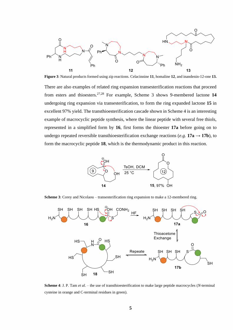
Figure 3: Natural products formed using zip reactions. Celacinnine 11, homaline 12, and inandenin-12-one 13.
There are also examples of related ring expansion transesterification reactions that proceed
from esters and thioesters.27,28 For example, Scheme 3 shows 9-membered lactone 14
undergoing ring expansion via transesterification, to form the ring expanded lactone 15 in
excellent 97% yield. The transthioesterification cascade shown in Scheme 4 is an interesting
example of macrocyclic peptide synthesis, where the linear peptide with several free thiols,
represented in a simplified form by 16, first forms the thioester 17a before going on to
undergo repeated reversible transthioesterification exchange reactions (e.g. 17a → 17b), to
form the macrocyclic peptide 18, which is the thermodynamic product in this reaction.
Scheme 3: Corey and Nicolaou – transesterification ring expansion to make a 12-membered ring.
Scheme 4: J. P. Tam et al. – the use of transthioesterification to make large peptide macrocycles (N-terminal
cysteine in orange and C-terminal residues in green).

6
However, transamidation/transesterification reactions become far less effective when trying
to make medium-sized rings which are less than ten atoms in size.21 This is largely due to
the destabilising transannular interactions which are very often present between the
functional groups in functionalised medium-sized rings (e.g. torsional strain and lone pair
repulsion). This problem is especially important in reactions under thermodynamic control
(which transamidation reactions usually are), because if the precursors are lower in energy
than the ring expanded products, this renders ring expansion unfeasible via this approach.
1.2.2 Radical Cascade Reactions
The formation of medium-sized rings and macrocycles via ring expansion reactions which
involve free radical intermediates has been well documented in the literature.29 Many radical
cyclisations involve a single ring expansion step, such as the Dowd–Beckwith reaction,
shown in Scheme 5.30 In this example, pentanone (19) was alkylated with dibromomethane
to form 20. The bromine in 20 was abstracted by a tributyltin radical generated using
classical azobisisobutyronitrile (AIBN) initiation, to give the free radical intermediate 21a,
which then cyclises to form a cyclopropane unit, giving the bicyclic intermediate 21b. The
bridging bond of the bicyclic intermediate 21b then fragments, forming cyclohexane
structure 21c, in which the radical is much more stable. Finally, this radial goes on to abstract
a hydrogen from tributyltin hydride to give the target molecule 22 in a yield of 73%. This is
a simple example of how free radicals can be used in a ring expansion.
Scheme 5: Free radical ring expansion of 5-membered ring 18 into 6-membered ring 21.
Free radical ring expansion can also be paired with other ring expansion reactions as part of
sequential ring expansion strategies. Dowd and Zhang introduced sequential ring expansions
mediated by free radical generation,31 allowing for the generation of much larger cyclic
7
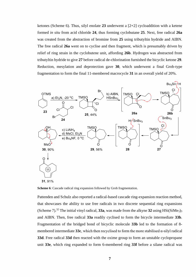
ketones (Scheme 6). Thus, silyl enolate 23 underwent a [2+2] cycloaddition with a ketene
formed in situ from acid chloride 24, thus forming cyclobutane 25. Next, free radical 26a
was created from the abstraction of bromine from 25 using tributyltin hydride and AIBN.
The free radical 26a went on to cyclise and then fragment, which is presumably driven by
relief of ring strain in the cyclobutene unit, affording 26b. Hydrogen was abstracted from
tributyltin hydride to give 27 before radical de-chlorination furnished the bicyclic ketone 29.
Reduction, mesylation and deprotection gave 30, which underwent a final Grob-type
fragmentation to form the final 11-membered macrocycle 31 in an overall yield of 20%.
Scheme 6: Cascade radical ring expansion followed by Grob fragmentation.
Pattenden and Schulz also reported a radical-based cascade ring-expansion reaction method,
that showcases the ability to use free radicals in two discrete sequential ring expansions
(Scheme 7).32 The initial vinyl radical, 33a, was made from the alkyne 32 using HSi(SiMe3)3
and AIBN. Then, free radical 33a readily cyclised to form the bicycle intermediate 33b.
Fragmentation of the bridged bond of bicyclic molecule 33b led to the formation of 8-
membered intermediate 33c, which then recyclised to form the more stabilised α-silyl radical
33d. Free radical 33d then reacted with the oxime group to form an unstable cyclopropane
unit 33e, which ring expanded to form 6-membered ring 33f before a silane radical was

8
ejected, thus propagating the chain, and forming the ring expanded oxime 34, in a good yield
of 70%.
Scheme 7: Radical cascade for the conversion of four membered ring oxime 31 into 6 and 5 membered bicyclic
oxime 34.
1.2.3 Fragmentation Reactions
A classic method for forming macrocycles from polycyclic precursors is through sigma-
bond fragmentation of bicyclic precursors. This is arguably best demonstrated through
Grob/Wharton/Eschenmoser-type fragmentations,33 which are all reactions in which a
bridging bond in a bicyclic starting material fragments, forming a single, larger ring. Work
done by Thommen et al., shows an impressive example of a reaction sequence featuring
sequential Grob fragmentation reactions, in which 15-membered ketone 41 was made from
the tricyclic ketone 35 (Scheme 8).34 Reduction of ketone 35 gave the tricyclic triol 36, which
was tosylated to give 37. Diol 37 underwent Grob fragmentation promoted by tert-butoxide,
thus ejecting the tosylate group, resulting in the ring expansion of 37 into 38 in a yield of
59%. The Grob fragmentation process was then repeated, with reduction of ketone 38 using
lithium aluminium hydride to give diol 39, tosylation to form 40 then a second Grob
fragmentation to furnish the 15-membered ketone 41, with defined Z,Z stereochemistry, in
excellent yield of 90%.

9
Scheme 8: Double ring expansion via Grob fragmentation.
As detailed before (Scheme 6), Grob fragmentation can be used in conjunction with other
ring expansion reactions. This is demonstrated by Ikeda et al 35 in the synthesis of the natural
product (±)-phoracantholide M (Scheme 9). In this example, an initial Grob-type
fragmentation (44 → 46) preceded an oxidative ring expansion fragmentation of bicyclic
molecule 46, to form the 12-membered lactone 47. Initial cyclisation of tethered alkene 42
was achieved through a [2+2] photocycloaddition, forming the strained tricyclic structure of
43. Mesylation of the alcohol 43 gave 44, which underwent Grob fragmentation giving 45,
which tautomerised to form the bicyclic ether 46. Oxidation of the more nucleophilic alkene
of diene 46 to epoxide 47 with m-CPBA and subsequent ring expansion of 47 furnished the
12-membered lactone 48 in a yield of 58%.
Scheme 9: Grob fragmentation followed by oxidative expansion leading to a cascade ring expansion.
Work from Maio et al.36 shows an interesting oxidative fragmentation reaction preceding
transesterification to give sequential ring expansions, thus forming the 11-membered lactone
10
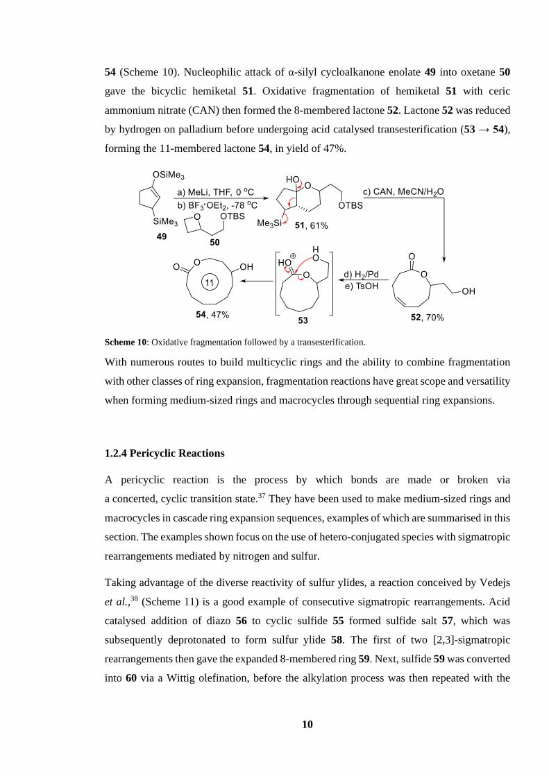
54 (Scheme 10). Nucleophilic attack of α-silyl cycloalkanone enolate 49 into oxetane 50
gave the bicyclic hemiketal 51. Oxidative fragmentation of hemiketal 51 with ceric
ammonium nitrate (CAN) then formed the 8-membered lactone 52. Lactone 52 was reduced
by hydrogen on palladium before undergoing acid catalysed transesterification (53 → 54),
forming the 11-membered lactone 54, in yield of 47%.
Scheme 10: Oxidative fragmentation followed by a transesterification.
With numerous routes to build multicyclic rings and the ability to combine fragmentation
with other classes of ring expansion, fragmentation reactions have great scope and versatility
when forming medium-sized rings and macrocycles through sequential ring expansions.
1.2.4 Pericyclic Reactions
A pericyclic reaction is the process by which bonds are made or broken via
a concerted, cyclic transition state.37 They have been used to make medium-sized rings and
macrocycles in cascade ring expansion sequences, examples of which are summarised in this
section. The examples shown focus on the use of hetero-conjugated species with sigmatropic
rearrangements mediated by nitrogen and sulfur.
Taking advantage of the diverse reactivity of sulfur ylides, a reaction conceived by Vedejs
et al.,38 (Scheme 11) is a good example of consecutive sigmatropic rearrangements. Acid
catalysed addition of diazo 56 to cyclic sulfide 55 formed sulfide salt 57, which was
subsequently deprotonated to form sulfur ylide 58. The first of two [2,3]-sigmatropic
rearrangements then gave the expanded 8-membered ring 59. Next, sulfide 59 was converted
into 60 via a Wittig olefination, before the alkylation process was then repeated with the

11
addition of diazo 61 to form the ylide 62, followed by a sigmatropic rearrangement to form
the 11-membered sulfide ring 63, with Z,Z stereochemistry.
Scheme 11: Successive sigmatropic rearrangement using sulfur ylides to form an 11-membered ring.
This strategy of consecutive ring expansion via sigmatropic rearrangements of cyclic
sulfides was simplified and expanded by Schmid et al.39 who built upon the procedure
presented by Vedejs through simple alkylation of cyclic sulfides using alkyl halides and TFA
as part of a two-step addition/expansion. This is illustrated in Scheme 12; alkylation of
sulfide 55 with allyl bromide which gave sulfide salt 64, and subsequent deprotonation with
potassium hydroxide gave sulfur ylide 65. Ylide 65 then rearranged to give the ring expanded
sulfide 66. This is the key point where Schmid’s sigmatropic rearrangement approach differs
to that of Vedejs is that 66 now is ready for alkylation without further modification, making
cascade ring expansions much easier in fewer steps. Thus, Scheme 12 also shows a second
iteration of alkylation/expansion forming the 11-membered ring 69 with overall yield of
49%.
Scheme 12: Ring expansion via alkylation and sigmatropic rearrangement.
12
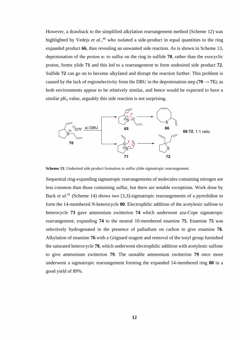
However, a drawback to the simplified alkylation rearrangement method (Scheme 12) was
highlighted by Vedejs et al.,40 who isolated a side-product in equal quantities to the ring
expanded product 66, thus revealing an unwanted side reaction. As is shown in Scheme 13,
deprotonation of the proton α- to sulfur on the ring in sulfide 70, rather than the exocyclic
proton, forms ylide 71 and this led to a rearrangement to form undesired side product 72.
Sulfide 72 can go on to become alkylated and disrupt the reaction further. This problem is
caused by the lack of regioselectivity from the DBU in the deprotonation step (70 → 71); as
both environments appear to be relatively similar, and hence would be expected to have a
similar pKa value, arguably this side reaction is not surprising.
Scheme 13: Undesired side product formation in sulfur ylide sigmatropic rearrangement.
Sequential ring-expanding sigmatropic rearrangements of molecules containing nitrogen are
less common than those containing sulfur, but there are notable exceptions. Work done by
Back et al.41 (Scheme 14) shows two [3,3]-sigmatropic rearrangements of a pyrrolidine to
form the 14-membered N-heterocycle 80. Electrophilic addition of the acetylenic sulfone to
heterocycle 73 gave ammonium zwitterion 74 which underwent aza-Cope sigmatropic
rearrangement, expanding 74 to the neutral 10-membered enamine 75. Enamine 75 was
selectively hydrogenated in the presence of palladium on carbon to give enamine 76.
Alkylation of enamine 76 with a Grignard reagent and removal of the tosyl group furnished
the saturated heterocycle 78, which underwent electrophilic addition with acetylenic sulfone
to give ammonium zwitterion 79. The unstable ammonium zwitterion 79 once more
underwent a sigmatropic rearrangement forming the expanded 14-membered ring 80 in a
good yield of 89%.

13
Scheme 14: Consecutive aza-Cope sigmatropic rearrangement.
Scheme 15 shows a tertiary amine mediated sigmatropic rearrangement by Suh et al.,42 who
demonstrated the use of aza-Claisen rearrangements in consecutive ring expansions in their
total syntheses of fluvirucinines. Enolisation of the cyclic amide 81 to enolate 82 gave the
conjugation needed for the aza-Claisen rearrangement. This rearrangement proceeded via
the breaking of the cyclic N-C bond and formation of the cyclic C-C σ-bond and
thermodynamically favoured E-isomer π-bond in turn expanding the ring into the medium-
sized lactam (83). After several steps (83 → 84, not shown) the same process was repeated
to convert 85 into 87. Cyclic secondary amine 85 was then acylated before undergoing
enolization and sigmatropic rearrangement to give lactam 87 in good yield of 74%.
Scheme 15: aza-Claisen rearrangements giving ring expanded macrocycles.

14
A creative method of expanding a ring in an iterative fashion is presented by Seyden-Penne
et al. 43 who reported a way to expand saturated lactones by one carbon at a time. This is
done through the generation of chlorocarbenes and their subsequent cycloaddition with silyl
enolates to form cyclopropane units which collapse into rings one atom larger than the
precursor (Scheme 16). Starting with enolization of lactone 88, silyl enolate 89 was reacted
with a chlorocarbene (formed in situ) to form the strained bicyclic system 90 which readily
collapsed into the much less strained lactone 91. After hydrogenation (91 → 92), the same
process can be repeated until the desired sized lactone is formed, in this case a 10-membered
lactone was formed (93) through two more iterations.
Scheme 16: Formation of macrocycles through iterative carbene cyclopropanation and expansion.
This single atom ring expansion strategy could theoretically be performed any number of
times to make any ring size desired; however, the overall yield of 88 → 92 is 63%, and this
restricts the utility of the reaction somewhat, as after only three iterations, the ring is
expanded by three atoms with an overall yield of 25%. Compared to other methods which
allow for ring expansion of similar magnitudes with higher yields, single atom ring
expansion is therefore less favourable, at least when larger changes in ring size are required.
1.2.5 Ring Expansion Metathesis Polymerisation
Olefin metathesis is a reaction popular in synthesis that involves the exchange of substituents
between a pair of alkenes to generate a new pair of different alkenes.44 This reaction has
been expanded on greatly since its inception, and has been used in many areas of synthetic
chemistry, including macrocycle formation. However, many methods to make macrocycles
through metathesis do so through ring-closing metathesis (RCM),45 using a long, linear
precursor, which can encounter the same problems with competing intermolecular reaction

15
discussed earlier.13 In order to avoid this, metathesis can be used to expand the size of an
olefin containing cyclic compounds.
Scheme 17 is an example of ring expansion metathesis polymerisation (REMP), first
showcased by Grubbs et al. 46,47 Cyclopentene 95, Grubbs catalyst II (94) and acyclic diene
96 were heated at reflux for 12 hours in DCM to yield the ring expanded product 100 in
43% yield, in going from a 5-membered ring to an 18-membered ring. Mechanistically, this
proceeded through the ring opening metathesis of 95 to form 97b, which underwent cross
metathesis with diene 96 to award the long linear diene 98. Diene 98 then underwent ring
closing metathesis (RCM) using the same catalyst 94 to yield the final macrocycle 100 in
yield of 43%. Scheme 16 shows the formation of an 18-membered ring using the bis-vinyl
ketone 96 which reacts selectively with terminal olefins in excellent yields, minimising by-
products and driving the reaction forward. The largest ring size reported in this manuscript
using REMP was 26, however, it is worth noting that once ring opening metathesis of
pentene (95) occurs, the molecule becomes linear. For this reason, it could be argued that
with the ring opening of pentene (97a → 97b) diminishes the advantages that ring expansion
has over end-to-end cyclisation.
Scheme 17: Formation of 18-membered macrocycle 100 through REMP.

16
This idea was developed further by Veige et al.,48 who reported a tungsten catalyst (101)
able to cyclise norbornene monomers into a single large cyclic polymer using successive
REMP in a catalytic cycle. A generic example is shown in Scheme 18, in which an n number
of norbornene units are cyclised to form a ring which is 5n carbons in size.
Scheme 18: Catalytic cycle of successive REMP through polymerisation of norbornene units.
Tungsten catalyst 101 is activated by a norbornene through the [2+2] cycloaddition between
the alkene group of the norbornene and the catalyst to form complex 103a. Intermediate
103a then underwent a [2+2] cycloaddition to give the less strained active catalyst 103b,
possessing a reactive alkene which underwent metathesis with another norbornene,
expanding the intermediate ring, to give 103c. This process is repeated until the intermediate
undergoes a final RCM step, to yield a macrocycle with 5n carbons in size, where n is the
number of norbornene units. Once the macrocycle product is detached (103c → 104) the
active catalyst 103b can go on to react further to generate more macrocyclic polymers. A
noteworthy point is the ring expanded macrocycle contains only cis alkene isomers, and is
highly syndiotactic, demonstrating the stereoselectivity of the catalyst.
Although REMP allows for the construction of large macrocycles and cyclic polymers alike,
there are few examples of using pre-functionalised rings and reagents, most likely due to the
difficulty of finding suitable reaction conditions that avoid competing cross metathesis and

17
linear polymerisation.47 This somewhat limits the scope of this reaction for the synthesis of
bioactive molecules and natural products, and at present, there are no examples of this
method being used in total synthesis.
1.2.6 Rhodium-Catalysed Ring Expansion
Over the past decade there has been keen interest in the use of rhodium complexes to expand
strained cyclopropane/cyclopropene rings into larger medium sized rings via the generation
of rhodacyclopentanones.49 Expansion of a ring through the insertion of a rhodium complex
was first reported in 2010 by Wang et al.,50 who expanded a strained cyclopropene unit into
a 5,6-bicyclic molecule in a Rh(I)-catalysed carbonylative carbocyclisation reaction
(Scheme 19).
The catalytic cycle is summarised in Scheme 19, for the formation of bicyclic amine 108
from propene 105 using [Rh(CO)2Cl]2 (5% mol) in DCE at 80 oC for 12 h. The rhodium
catalyst undergoes an oxidative addition reaction via insertion into the cyclopropene 105 to
form intermediate 4-membered rhodium complex 106a, partially relieving the strain of the
previous cyclopropene unit. Insertion of carbon monoxide into the ring then increases the
size of the rhodium-containing ring from a 4- to a 5-membered ring, affording the
rhodacyclopentenone complex 106b which then undergoes a [3+1+2] cycloaddition with the
tethered alkyne, to give rhodium intermediate 106c. Reductive elimination of intermediate
106c then takes place to regenerate the active catalyst and yield the target 5,6-bicyclic
compound 107, which tautomerises to form the aromatic compound 108 in yield of 83%.

18
Scheme 19: Proposed catalytic cycle for Rh(I)-catalysed carbonylative carbocyclisation of cyclopropene.
This work has since been expanded on, by increasing the ring size of the target molecule and
by the introduction of heteroatoms into the ring. Bower et al. showcase both of these features
in their work summarised in Scheme 20, with the directed ring expansion of an
aminocyclopropane into an 8-membered N-hetrocycle.51 The rhodium catalyst inserts into
cyclopropane unit of indole 109 to give the 4-membered rhodium ring 110a. Next, chelation
to the amide carbonyl group directs the insertion of CO, forming rhodacyclopentenone 110b.
The nucleophilic C3-position of the indole unit on 110b can coordinate to the rhodium metal
centre, a process termed “capture”, to form 110c, and the tricyclic structure 110c then
“collapses” by undergoing reductive elimination, in turn gaining a proton and forming the
8-membered target N-heterocycle 111, in a good yield of 77%.

19
Scheme 20: “Capture-collapse” directed carbonylative C-C ring expansion of aminocyclopropane.
It is also possible for rhodium to insert into cyclobutane units. Ito et al.52 showcased the
ability of rhodacyclopentanone complexes to form lactones from cyclobutene units via the
ring expansion of cyclobutanone 112 (Scheme 21). In this study, the rhodium complex
inserts into the cyclobutanone unit of 112 to generate rhodacyclopentanone complex 113a.
Thus, the rhodium atom first coordinated to the phenolic hydroxy group of 112, bringing the
rhodium into close proximity to the α C-C bond, allowing for insertion and formation of
113b, and finally, β-hydride elimination yields the target 7-membered lactone 114 in 86%
yield. It is worth noting that although the reaction was carried out under a CO atmosphere,
CO is not directly involved in the reaction mechanism unlike previous rhodium-catalysed
ring expansion reactions (See Scheme 19).
Scheme 21: Lactone formation by rhodium‐catalyzed C−C bond cleavage of cyclobutanone.

20
1.2.7 Successive Ring Expansion
Successive ring expansion (SuRE) is a method pioneered in York by Unsworth et al.,53 and
is based on the iterative insertion of hydroxy acids/amino acid derivatives into cyclic β-
ketoesters to form lactones/lactams. The iterative nature of the method enables ring
expansion to be performed several times to form a range of different sized rings via a
relatively short reaction sequence. An early example is summarised in Scheme 22. In this
reaction, 12-membered β-ketoester 115 was reacted with acid chloride 116 in the presence
of magnesium chloride and pyridine to promote acylation of the β-ketoester. Following
acylation, the Fmoc protecting group on the tethered amine of 117 was cleaved using
piperidine, exposing primary amine 118a which then underwent rapid cyclisation to form
118b, via a 6-membered ring transition, and fragmented to form the ring expanded
macrocyclic lactam 119, in an impressive overall yield of 80%. As the product 119 also
contains a cyclic β-ketoester motif, the same sequence of reactions can then be repeated;
thus, the process was repeated using the same conditions, to yield the 20-membered
macrocycle 120, and then again to form the large 24-membered macrocycle 121.
Scheme 22: Successive ring expansion reactions with β-amino acid fragments.
21
Successive ring expansion allows for the acylation of rings with amino acid fragments
varying from three or four atoms long, and the high yielding nature of successive ring
expansion allows for up to three iterations, before inefficient acylation prevents further
expansion. This makes it an appealing and practical route for macrocycle synthesis. The
linear fragments can be pre-functionalised with a variety of useful handles before ring
expansion, make SuRE an attractive way to construct diverse functional macrocycles and
medium sized rings, and to exemplify this, the group used the method to create a of library
medium-sized ring scaffolds for inclusion in a high-throughput-screening library. 54
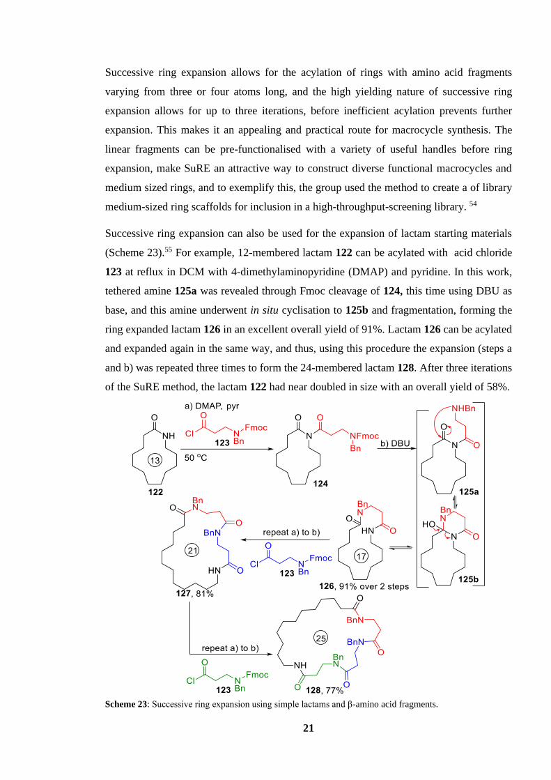
Successive ring expansion can also be used for the expansion of lactam starting materials
(Scheme 23).55 For example, 12-membered lactam 122 can be acylated with acid chloride
123 at reflux in DCM with 4-dimethylaminopyridine (DMAP) and pyridine. In this work,
tethered amine 125a was revealed through Fmoc cleavage of 124, this time using DBU as
base, and this amine underwent in situ cyclisation to 125b and fragmentation, forming the
ring expanded lactam 126 in an excellent overall yield of 91%. Lactam 126 can be acylated
and expanded again in the same way, and thus, using this procedure the expansion (steps a
and b) was repeated three times to form the 24-membered lactam 128. After three iterations
of the SuRE method, the lactam 122 had near doubled in size with an overall yield of 58%.
Scheme 23: Successive ring expansion using simple lactams and β-amino acid fragments.
22
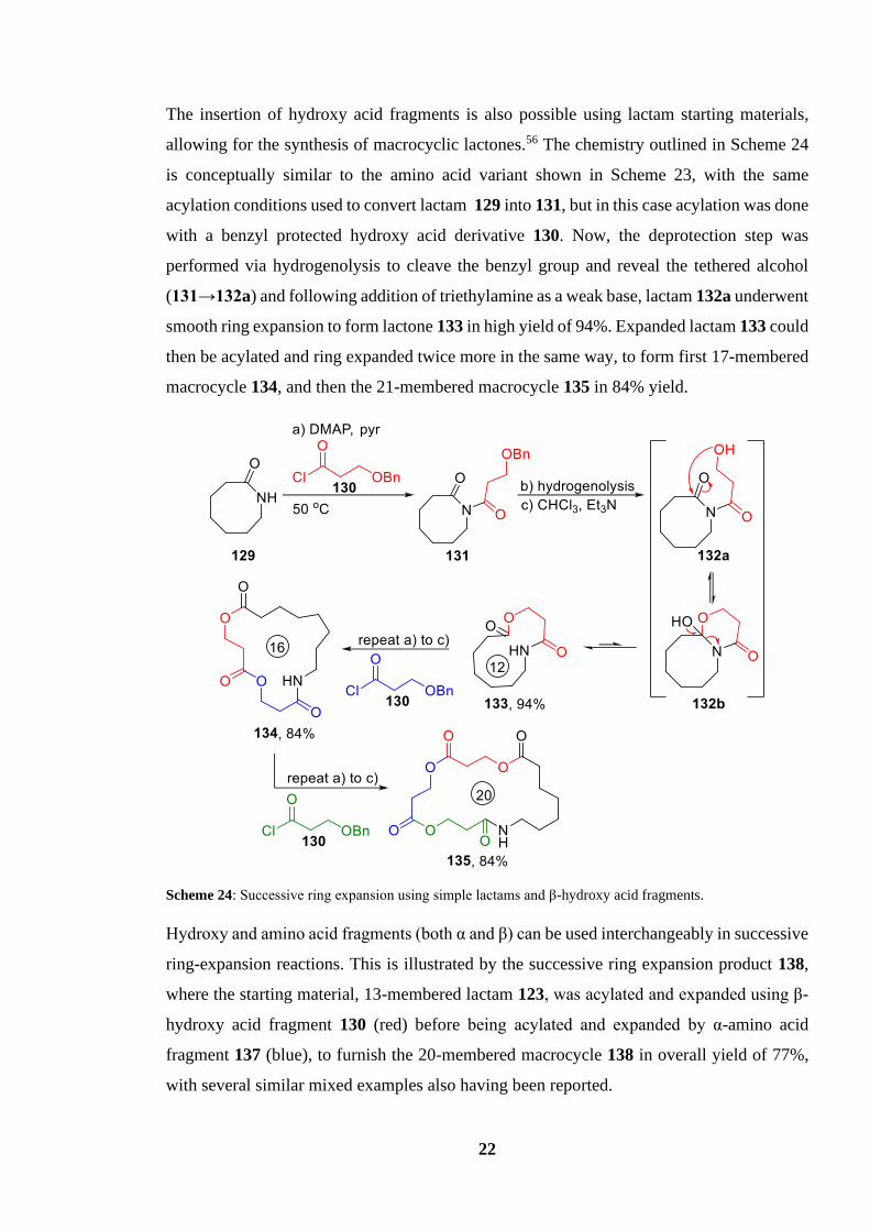
The insertion of hydroxy acid fragments is also possible using lactam starting materials,
allowing for the synthesis of macrocyclic lactones.56 The chemistry outlined in Scheme 24
is conceptually similar to the amino acid variant shown in Scheme 23, with the same
acylation conditions used to convert lactam 129 into 131, but in this case acylation was done
with a benzyl protected hydroxy acid derivative 130. Now, the deprotection step was
performed via hydrogenolysis to cleave the benzyl group and reveal the tethered alcohol
(131→132a) and following addition of triethylamine as a weak base, lactam 132a underwent
smooth ring expansion to form lactone 133 in high yield of 94%. Expanded lactam 133 could
then be acylated and ring expanded twice more in the same way, to form first 17-membered
macrocycle 134, and then the 21-membered macrocycle 135 in 84% yield.
Scheme 24: Successive ring expansion using simple lactams and β-hydroxy acid fragments.
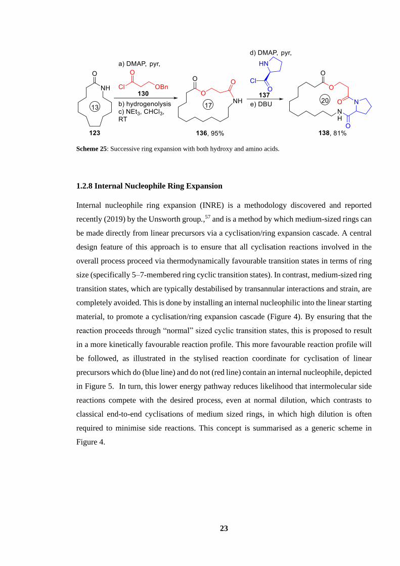
Hydroxy and amino acid fragments (both α and β) can be used interchangeably in successive
ring-expansion reactions. This is illustrated by the successive ring expansion product 138,
where the starting material, 13-membered lactam 123, was acylated and expanded using β-
hydroxy acid fragment 130 (red) before being acylated and expanded by α-amino acid
fragment 137 (blue), to furnish the 20-membered macrocycle 138 in overall yield of 77%,
with several similar mixed examples also having been reported.
23
Scheme 25: Successive ring expansion with both hydroxy and amino acids.
1.2.8 Internal Nucleophile Ring Expansion
Internal nucleophile ring expansion (INRE) is a methodology discovered and reported
recently (2019) by the Unsworth group.,57 and is a method by which medium-sized rings can
be made directly from linear precursors via a cyclisation/ring expansion cascade. A central
design feature of this approach is to ensure that all cyclisation reactions involved in the
overall process proceed via thermodynamically favourable transition states in terms of ring
size (specifically 5–7-membered ring cyclic transition states). In contrast, medium-sized ring
transition states, which are typically destabilised by transannular interactions and strain, are
completely avoided. This is done by installing an internal nucleophilic into the linear starting
material, to promote a cyclisation/ring expansion cascade (Figure 4). By ensuring that the
reaction proceeds through “normal” sized cyclic transition states, this is proposed to result
in a more kinetically favourable reaction profile. This more favourable reaction profile will
be followed, as illustrated in the stylised reaction coordinate for cyclisation of linear
precursors which do (blue line) and do not (red line) contain an internal nucleophile, depicted
in Figure 5. In turn, this lower energy pathway reduces likelihood that intermolecular side
reactions compete with the desired process, even at normal dilution, which contrasts to
classical end-to-end cyclisations of medium sized rings, in which high dilution is often
required to minimise side reactions. This concept is summarised as a generic scheme in
Figure 4.

24
Figure 4: Model demonstrating function of the internal nucleophilic catalyst (green) in an internal nucleophile
ring expansion reaction.
Figure 5: Hypothetical reaction coordinate of a generic INRE reaction.
An illustrative example is shown in Scheme 26, for the lactonisation of linear biaryl acid
144. First, carboxylic acid 144 is activated by the coupling reagent propanephosphonic acid
anhydride (T3P) to form the activated acid 145. It is then proposed that the pyridine motif
present in 145 attacks the activate acid intramolecularly to form the positively charged 6-
membered ring acyl ammonium intermediate 146a. The tethered alcohol of 146a can then
attack the same carbonyl, forming bicyclic intermediate 146b, before fragmenting to form
the medium sized lactone 147, in an excellent yield of 90%. Crucially, if the same conditions
are used on an analogous starting reagent lacking an internal nucleophile pyridine (148), the
only product isolated is dimer 150, with none of lactone 149 formed, clearly highlighting the
importance of the internal N-nucleophile (Scheme 27).
With internal
nucleophile
141 → 143
Without internal
nucleophile
139 → 140
139 140
141 142 143

25
Scheme 26: INRE with a biaryl linear precursor.
Scheme 27: Dimerization of N-free precursor 148.
An interesting feature of INRE is its atroposelectivity. Atropisomerism can play a vital role
in drug discovery and development, given the key role shape and conformation play in any
ligand-target interaction in biology.58 Due to the biaryl nature of the compound there is a
lack of free rotation around the C-C bond connecting the two aryl groups in the products
(supported by DFT studies). As a result of this, it is possible to form and isolate single
atropisomers of medium-sized ring products using this chemistry. For example, in biaryl
systems containing secondary alcohols as the terminal nucleophile, two atropisomers are
possible, but only one atropisomer is formed exclusively. Scheme 28 shows a kinetic model
for why it is thought that only one atropisomer is observed, based on a sterically preferred
Si face attack to form the acyl ammonium intermediate.

26
It is proposed that the 6-membered transition state 146a is similar to that of a chair/boat-like
conformation. The observed stereochemical outcome 147(i) arises from the facial selectivity
of the alcohol attacking the prochiral intermediate N-acylammonium ion, and when attacking
via the Si face, this places the methyl group of the secondary alcohol in a pseudo-equatorial
orientation (146a → 146b(i)). However, when the alcohol attacks the Re face (146a →
146b(ii)), this would force the methyl group to be in a pseudo-axial orientation, presumably
resulting in increased steric repulsion, and leading to the transition state being higher in
energy.
Scheme 28: A kinetic model based on diastereoselective attack into prochiral N-acyliminiumion
It is also possible to use INRE with precursors which use free amines instead of alcohols as
the terminal nucleophile to form lactams, such as 155 → 156 (Scheme 29). Equally, aliphatic
tertiary amines can be used as the internal nucleophilic catalyst (151 → 152), and the length
of the linear precursor can also be varied, with ring sizes from 8 (lactone 154) to 11 atoms
(lactone 152) all being made via INRE.

27
Scheme 29: Diverse selection of INRE reactions.
1.3 Project Aims
Heterocyclic medium-sized rings and macrocycles are interesting compounds in medicinal
chemistry, and developing improved ways to make complex systems of this type is
important.59 Therefore, in this project, we wanted to further develop the INRE strategy, with
specific focus on the development of more elaborate cascade sequences to form larger, more
complex ring systems more quickly. Thus, a new strategy was conceived, whereby longer
linear precursors would be designed, that contain more than one internal nucleophile. In
theory, this would allow for multiple cyclisation/expansion processes in a single cascade
sequence, thus enabling the formation of larger macrocycles from a linear precursor in one
pot, in a multi internal nucleophile induced ring expansion (multi-INRE).
A generic representation of this concept is shown is Scheme 30, where “X” and “Y”
represent internal nucleophiles and “ZH” signifies a terminal nucleophile. Thus, a linear

28
precursor 159 would be activated by a coupling reagent before cyclising to form the
intermediate 160a. The carbonyl of this intermediate could then be attacked by the internal
nucleophile ‘Y’ of 160a to form the 10-membered intermediate 160b, before finally being
attacked by the tethered nucleophile ‘ZH’ and expanded again, to form the ring expanded
14-membered macrocycle product 161. As with single internal nucleophile ring expansion,
the system in question is expected to follow a more kinetically favourable reaction profile
when compared with the analogous direct end-to-end cyclisation. Figure 6 illustrates a
hypothetical reaction coordinate for cyclisation of a generic linear precursor which
constitutes two internal nucleophiles. Intriguingly, there is also no obvious reason why the
linear starting material could not be extended even further to include more internal
nucleophiles.
Scheme 30: Example of an internal nucleophile ring expansion reaction with two internal nucleophiles.
Figure 6: Hypothetical reaction coordinate of a general multi-INRE reaction.
160a 160
b
Without internal
nucleophiles
With internal
nucleophiles
159 → 161

29
The overriding aim of this project was to establish the multi-INRE concept as an important
new method for macrocycle synthesis. To facilitate this, the following objectives were
devised:
• To explore the viability of the multi-INRE strategy using a simple model system.
• To optimise the multi-INRE reaction by screening against an array of different
reaction conditions.
• To explore the scope and limitations of the multi-INRE strategy by building and
testing an assortment of linear precursors.
• To gain insight into the diastereoselectivity of multi-INRE when used on longer
precursors.
• To gain further insight into the mechanistic pathway by which INRE proceeds.

30
Initial Multi-Internal Nucleophile Ring Expansion Precursor Design
and Synthesis
2.1 Designing an Initial Precursor
To explore the viability of a multi-INRE system with more than one internal nucleophile,
we first designed a linear starting material that contains two internal nucleophiles which
were previously shown to be successful in single-INRE reactions in the Unsworth group.57
It was hoped that by incorporating an additional nucleophile into a system already known to
undergo single-INRE with one internal nucleophile, it would allow two successive ring
expansions to occur in a cascade process. It was also hoped that the toolbox of synthetic
procedures already in place for making single-INRE precursors would facilitate the
preparation of novel multi-INRE precursors.
The first precursor conceived, and the proposed multi-INRE mechanistic pathway, is shown
in Scheme 31. The precursor 162 is based on the use of two tertiary amine groups as the
internal nucleophiles, the first a pyridine, which was the most successful internal nucleophile
in the previous Unsworth group work, and the second a simple aliphatic tertiary amine. The
idea was that the carboxylic acid in 162 would be activated by a suitable coupling agent
before undergoing nucleophilic attack with the pyridine internal nucleophile to give the first
intermediate 163a, a 6-membered pyridinium ring. The hope then was that the carbonyl
generated would then be electrophilic enough to be attacked by the second internal
nucleophile, the tertiary amine, to give the 10-membered ammonium ring 163b. Then, the
10-membered intermediate 163b would be primed to undergo another ring expansion as the
terminal alcohol attacks the electrophilic carbonyl moiety to open the ring and form
macrocyclic lactone 164.

31
Scheme 31: Mechanistic pathway of ring expansion using precursor 162.
Scheme 32 shows our planned retrosynthetic route to precursor 151. It was envisaged that
the initial precursor 151 would be constructed from the pyridine 160 containing two
synthetic handles; an ortho-halide for cross-coupling and an ortho-methyl group suitable for
lithium ion-trapping.
Protection of the carboxylic acid when building the precursor was thought to be prudent to
avoid unwanted side reactions, and this could be done via esterification. The key
retrosynthetic disconnection would be the C-C biaryl bond, which splits the precursor into
two synthetic targets, aryl halide 167 and borylated aryl ester 166, which would be connected
through a cross-coupling reaction. Borylated aryl ester 166 would be accessed through a
Miyaura cross-coupling between haloaryl ester 168 and B2Pin2. The tertiary amine internal
nucleophile present in pyridine 167, would be prepared via an SN2 reaction between
secondary amine 169 and alcohol 170. Finally, secondary amine 169 would be synthesised
via lithiation-trapping of the 2-methyl present in pyridine 171 with electrophilic imine 172.
With a synthetic strategy in place, the synthesis of a haloaryl of the form 169 was attempted.

32
Scheme 32: Retrosynthetic route towards the initial multi-INRE precursor 162.
2.2 Building Initial Multi-INRE Precursor 162
We started by seeking to establish conditions for the lithiation-trapping of bromopyridine
173 with imine 172. Several lithiation-trapping reactions were performed using conditions
previously identified for similar reactions.57 Table 1 shows all the different conditions tested,
each with their respective yield. Thus, when using two equivalents of both imine 172 and
LDA (Entry 1) a moderate yield of 70% was obtained for amine 174. However, both TLC
and 1H NMR spectroscopy analysis of the unpurified reaction mixture showed pyridine 173
was still present. In an attempt to convert all starting material 173 into product, the reaction
time was increased from 30 minutes to two hours (Entry 2), which led to an increase in yield
to 81%. Next, we questioned whether the use of two equivalents of LDA was necessary,
given that only one deprotonation was required; thus, the reaction was trialled using reduced
equivalents of LDA (1.2 equiv.) but this led to a significant drop in yield from 81% to 60%
(Entry 3). Furthermore, a number of uncharacterisable side-products were also observed by
TLC and 1H NMR spectroscopy under these conditions, most likely caused by the

33
polymerisation of 173 via SNAr. Simultaneously, a lithiation-trapping reaction with both
reduced equivalents of imine 172 and LDA was trialled in the same hope of generating a
more efficient lithiation-trapping reaction (Entry 4). Using only 1.5 equivalents of imine 172
and LDA gave the best result, furnishing amine 174 in 80% yield; this result was particularly
pleasing as the amount of imine 172 could be reduced, allowing for a more efficient
synthesis.
Table 1: Lithiation trapping optimisation for amine 174 synthesis
Entry LDA (Equiv.) Imine 172 (Equiv.) Reaction Time (b) / h Yield / %
1 2.0 2.0 0.5 70
2 2.0 2.0 2 81
3 1.2 2.0 2 60
4 1.2 1.5 2 80
The next step in the synthesis towards precursor 162 was the alkylation of secondary amine
174. It was envisioned that an SN2 reaction between amine 174 and a halogenated propanol
should be an efficient and high yielding way to install the terminal alcohol group. However,
this reaction transpired to be the most challenging to optimise, with the conditions of the SN2
reaction requiring five revisions until the yield was brought up to an acceptable level.
Scheme 33 shows the different reaction conditions tested for the synthesis of alcohol 176.
Scheme 33 (i) shows the first attempted SN2 reaction, in which amine 174 was heated at
reflux in acetonitrile for three hours with 2.0 equivalents of potassium carbonate and 1.5
equivalents of chloropropanol 175. Surprisingly, TLC and 1H NMR spectrum analysis of the
unpurified reaction mixture showed no evidence of product 176 being formed, despite
believing that secondary amine 174 would be reactive enough to undergo the desired SN2
reaction. This lack of reactivity is thought to be caused by amine 174 being a worse
nucleophile than initially thought.
In an attempt to improve the reactivity, bromopropanol 177 was used instead of
chloropropanol 175 in the hope that this switch to a superior leaving group would help
promote the SN2 reaction (Scheme 33 (ii)). The SN2 reaction was heated overnight to give
the best chance of success. This change did have a positive effect, with product 176 isolated
successfully, but the yield was poor (24%). TLC and 1H NMR spectrum analysis of the

34
unpurified reaction mixture again showed starting material 174 was still present, indicating
that the reaction did not go to completion. Scheme 33 (iii) shows the next modification:
leaving the reaction over the weekend to allow all starting material 174 to be consumed.
Pleasingly, the yield increased to 53%, however, starting material 174 was again identified
in the unpurified reaction mixture. This prolonged reaction time was also impractical, as a
three-day reaction would likely create a bottleneck in the synthesis of precursor 162.
More forcing conditions were therefore used in an attempt to convert all starting material
174 into product. Scheme 33 (iv) shows an increase in bromopropanol 177 equivalents to
2.5 afforded product 176 in a yield of 65%. However, starting material was still present in
the reaction mixture, suggesting that the yield of 176 could be increased further. Scheme 33
(v) showcases a final attempt to increase the yield, using a better electrophile, iodopropanol
178, at a higher concentration (0.5 M) to drive conversion of starting material 174 into
product 176. The reaction furnished alcohol 176 in a good yield of 75% which signifies a
major improvement upon the initial reactions. However, a small amount of starting material
174 was still identified from the unpurified reaction mixture in both TLC and 1H NMR
spectroscopy, albeit in much smaller quantities, suggesting that further optimisation could
still be possible in future studies. Use of a stronger base, such as sodium hydride, was
avoided as it was suspected that a stronger base would lead to the E2 elimination of the
haloalkane.
Scheme 33: SN2 reactions for precursor 164 synthesis.

35
The next step was to start making the other half of the precursor (166) needed to cross-couple
with bromopyridine 176. As previously shown in Scheme 32, the target molecule 166 should
possess a boron synthetic handle, which could be made from an aryl halide ester (168).
However, no such aryl halide ester was commercially available, so a commercially available
acid analogue, bromoaryl acid 179, was used instead and converted into an ester, via the
simple procedure shown in Scheme 34; thus, esterification of acid 179 using sulfuric acid in
methanol at reflux for 90 mins afforded methyl ester 180 in an excellent yield of 99%.
Scheme 34: Fischer esterification of aryl halide.
With the carboxylic acid group protected as a methyl ester, the bromide could now be
converted into the desired pinacol borate 181 using a Miyaura cross-coupling. Using
conditions based on previous literature,57 aryl bromide 180 was stirred in dioxane at 80 °C
overnight under argon with [1,1′-bis(diphenylphosphino)ferrocene]dichloropalladium(II),
potassium acetate, and bis(pinacolato)diboron to give aryl borate 181 in an isolated yield of
56% after purification (Scheme 35). While successful, this reaction was a bottleneck in the
construction of precursor 162 for several reasons. First, for the subsequent cross-coupling
reaction (166 + 167 →165) aryl borate 181 was used in excess of 2.0 equivalents, which
meant that a large quantity of 181 needed to be produced. This in turn required a relatively
large quantity of reagents, including a large amount of the expensive catalyst Pd(dppf)Cl2.
Second, the chromatographic purification of boronic ester pinacol 181 was extremely
difficult, especially on scales of 2 g and above. Analysis using 2D TLC revealed that boronic
ester pinacol 181 slowly decomposes on silica. This instability, coupled with the presence
of an undesired side-product in the crude reaction mixture, which had a similar Rf to the
boronic ester pinacol 170 in all tested solvent systems, made the isolation of 181 from
chromatographic purification very challenging. Third, to make purification easier, a
proportionally large column was required for the purification, which was costly in terms of
solvent, silica requirements, and in time. This limited the amount of product 181 which could
be successfully purified in a single column to 2 g, this required the purification of boronic
ester pinacol 181 to be performed in batches.

36
Scheme 35: Miyaura cross-coupling of aryl bromide 170 with bis(pinacolato)diboron.
Having successfully synthesised both halves of the target precursor 162, the next stage of
the synthesis was to couple the two molecules 176 and 181. Scheme 36 shows the Suzuki-
Miyaura cross-coupling reaction, which was adapted from conditions reported in the
literature.57 Aryl bromide 176 and boronic ester pinacol 181 were stirred overnight at 80 °C
under argon with potassium phosphate and Pd(dppf)Cl2 in a THF/H2O mixture to make the
biaryl 182 in a pleasingly high yield of 87%. As the Suzuki-Miyaura cross-coupling reaction
was high yielding, no further optimisation was required, and every repeated synthesis of 182
used the conditions shown in Scheme 36.
Scheme 36: Suzuki-Miyaura cross-coupling of boronic ester pinacol 181 and bromopyridine 176.
The final step in the synthesis of precursor 162 is the hydrolysis of the methyl ester 182
(Scheme 37). Typical ester hydrolysis conditions were used; ester 182 was stirred overnight
in a lithium hydroxide/THF solution at room temperature to yield the desired precursor 162.
Although it was thought that the hydrolysis cleanly converted all starting material 182 into
product 162, based on 1H NMR spectrum analysis, the product was still purified via column
chromatography to remove any trace impurities carried through from previous reactions.
After purification, precursor 162 was isolated in an excellent yield of 96%. The purified
product was isolated as a powder. We believe that hydroxy acid 162 takes the form of
zwitterion 162a based on typical acid and amine pKa values, however, the 1H NMR peaks
of environments near the protonated quaternary amine do not show a significant change in
chemical shift when compared to the 1H NMR of methyl ester 182, which would be expected
after protonating the tertiary amine.
37
Scheme 37: Hydrolysis of methyl ester 182.
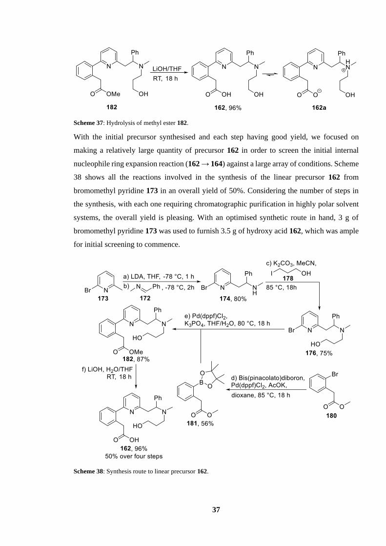
With the initial precursor synthesised and each step having good yield, we focused on
making a relatively large quantity of precursor 162 in order to screen the initial internal
nucleophile ring expansion reaction (162 → 164) against a large array of conditions. Scheme
38 shows all the reactions involved in the synthesis of the linear precursor 162 from
bromomethyl pyridine 173 in an overall yield of 50%. Considering the number of steps in
the synthesis, with each one requiring chromatographic purification in highly polar solvent
systems, the overall yield is pleasing. With an optimised synthetic route in hand, 3 g of
bromomethyl pyridine 173 was used to furnish 3.5 g of hydroxy acid 162, which was ample
for initial screening to commence.
Scheme 38: Synthesis route to linear precursor 162.

38
2.3 Initial Multi-INRE Reaction
With access to a sufficient quantity of precursor 162, we could now attempt a multi-INRE
reaction. The INRE reaction was performed on precursor 162 by adapting conditions
previously reported for ring expansion by the Unsworth group. It was assumed that more
energy would be required to promote this multi-INRE reaction as two successive
intramolecular nucleophilic substitutions needed to take place, compared to single-INRE
reactions which used precursors containing one internal nucleophile. With this considered,
the initial multi-INRE reaction using precursor 162 was heated overnight at reflux (60 °C)
to allow for the best chance of success (Scheme 39). Thus, hydroxy acid 162 was refluxed
in chloroform with the coupling agent T3P and DIPEA which afforded lactone 164 in an
isolated yield of 17%. Notably, biaryl lactone 164 was isolated as a single atropisomer, with
the reasoning behind this stereoselectivity explained below.
Scheme 39: First trialled multi-INRE using hydroxy acid 162.
Cyclisation of hydroxy acid 162 to form macrocyclic lactone 164 was confirmed by HRMS,
and IR, 1H NMR and 13C NMR spectroscopic analysis. Figure 7 shows the 1H NMR
spectrum of macrocyclic lactone 164 with all non-aromatic peaks assigned to their respective
environments. In lactone 164, free rotation is expected to be restricted relative to the linear
precursor; indeed, this is seen in the 1H NMR spectra, with the aliphatic protons that were
previously equivalent in precursor 162 distinguishable in the 1H NMR spectrum of
macrocyclic lactone 164. This is clearly seen with the CH2 protons adjacent to the carbonyl
in lactone 164 (Hj and Hk in Figure 7). In the linear precursor 162, the two protons are
indistinguishable by 1H NMR, however, due to the presumably more rigid confirmation, they
can be differentiated via 1H NMR spectroscopy, with Hj and Hk presenting a distinct doublet
at δH 4.46 and δH 4.00, respectively. Thus, with evidence obtained from the all spectroscopic
methods described, including the 1H NMR spectrum (Figure 7), we could confidently
confirm the synthesis of novel macrocyclic lactone 164 via a multi-INRE reaction, the first
of its kind.

39
Figure 7: 1H NMR Spectrum of multi-INRE product lactone 164.
The isolation and characterisation of macrocyclic lactone 164 demonstrates that INRE can
be achieved using linear precursors containing more than one internal nucleophile. This
gratifying discovery underpinned the direction taken for the rest of the project; focus was
turned towards increasing the yield and exploring the limitations of multi-INRE reactions
using linear precursors containing multiple internal nucleophiles.
Interestingly, analysis of the 1H and 13C NMR spectra of lactone 164 also gave additional
insight into the stereoselectivity of multi-INRE systems which use precursors containing
multiple internal nucleophiles. Both 1H and 13C NMR spectra provided evidence suggesting
that the multi-INRE reaction 162 → 164 produced only one diastereoisomer. Figure 9 shows
the 13C NMR spectrum of the isolated lactone 164, with all appropriate peaks assigned to
their respective carbon environment. The 13C NMR spectrum of lactone 164 shows a notable
absence of peaks corresponding to a chemically different diastereomer, suggesting that only
one diastereoisomer is formed in the multi-INRE reaction. It could be argued that such a
diastereoisomer could have been removed during chromatographic purification of the
unpurified reaction mixture containing lactone 164. However, only one macrocyclic
compound could be identified from 1H NMR spectroscopy of the unpurified reaction
mixture.
Hj
Hc
Hk
Hi
Ha+Hh Hb Hd He
CH3
Hg+Hf

40
Figure 8: Possible diastereoisomers which could yield from the multi-INRE reaction.
Figure 9: 13C NMR spectrum of macrocyclic lactone 164.
To assign the relative stereochemistry of 164, we turned to X-ray crystallography. Thus, a
crystal was grown (from 164) and the result is shown in Figure 10. The structure of the
crystal grown revealed it to be atropisomer 164(i), which possessed the same sense of
stereochemistry as that seen in the previously reported single-INRE biaryl lactone 147.57
g
b f
d
a
c d

41
Figure 10: Single crystal XRD structure of macrocyclic lactone 164(i).
This atroposelectivity is presumed to have the same origin as in the previous work, resulting
from facial selectivity of the attacking internal nucleophile. Similar to previous single-INRE
reactions, this system allows for point-to-axial chirality transfer.58 The atroposelectivity in
both single- and multi-INRE reactions can be explained using the same kinetic argument
(Scheme 40). It is presumed that the observed stereochemical outcome (formation of 164(i))
arises from the facial selectivity of the tertiary amine attacking into the prochiral
intermediate N-acylammonium ion, and when attacking via the Si face, it places the phenyl
group in a pseudo-equatorial orientation (163a → 163b(i)). However, when the tertiary
amine attacks the Re face (163a → 163b(ii)), this would force the phenyl group to be placed
in a pseudo-axial orientation, presumably causing steric hinderance, and leading to the
transition state being higher in energy, in turn preventing the formation of atropisomer
164(ii). It was pleasing to see that the diastereoselectivity of INRE reactions was transferred
when synthesising larger macrocycles from linear precursors containing two internal
nucleophiles.
164(i) (CCDC 2004423)
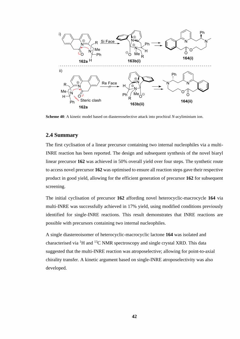
42
Scheme 40: A kinetic model based on diastereoselective attack into prochiral N-acyliminium ion.
2.4 Summary
The first cyclisation of a linear precursor containing two internal nucleophiles via a multi-
INRE reaction has been reported. The design and subsequent synthesis of the novel biaryl
linear precursor 162 was achieved in 50% overall yield over four steps. The synthetic route
to access novel precursor 162 was optimised to ensure all reaction steps gave their respective
product in good yield, allowing for the efficient generation of precursor 162 for subsequent
screening.
The initial cyclisation of precursor 162 affording novel heterocyclic-macrocycle 164 via
multi-INRE was successfully achieved in 17% yield, using modified conditions previously
identified for single-INRE reactions. This result demonstrates that INRE reactions are
possible with precursors containing two internal nucleophiles.
A single diastereoisomer of heterocyclic-macrocyclic lactone 164 was isolated and
characterised via 1H and 13C NMR spectroscopy and single crystal XRD. This data
suggested that the multi-INRE reaction was atroposelective; allowing for point-to-axial
chirality transfer. A kinetic argument based on single-INRE atroposelectivity was also
developed.

43
Multi-INRE Screening and Aliphatic Precursor Synthesis
3.1 Initial Screening of multi-INRE reaction 162 → 164
Having established that a multi-INRE reaction using a precursor containing two internal
nucleophiles is possible, the next step was to increase the yield of product 164 through
optimisation of reaction 162 → 164. This was done by testing a range of reaction conditions
for the INRE of precursor 162. Screening was carried out on 100 mg scale unless stated and
the variables changed during the initial screening process of reaction 162 → 164 were
solvent, temperature, reaction time, concentration, and coupling agent. Table 2 shows the
reaction conditions tested and the respective yield from each reaction.
Table 2: Initial screening conditions for reaction 162 → 164 and their respective isolated yields. a Performed
on 300 mg scale.
Entry Coupling
Agent Solvent
Concentration /
M Time
Temperature / oC
Yield /
%
1 T3P CHCl3 0.1 18 h 60 17a
2 T3P CHCl3 0.001 18 h 60 7
3 T3P DCE 0.1 18 h 85 9
4 T3P CHCl3 0.1 18 h 25 6
5 T3P CHCl3 0.1 1 w 60 8
6 T3P DMF 0.1 18 h 60 33
7 T3P DMA 0.1 18 h 60 19
8 CDI DMF 0.1 18 h 60 11
9 HATU DMF 0.1 18 h 60 19
First, the concentration of hydroxy acid 162 in solution was changed from 0.1 M to 0.001 M
(Table 2, Entry 2). It was assumed that a higher dilution would lower the probability of
hydroxy acid 162 reacting with other hydroxy acid molecules, and although ideally we did
not want to resort to high dilution in INRE reactions, we still considered that testing at lower
concentrations would allow for greater insight into multi-INRE systems. If a higher yield of
product 164 was observed using high dilution, it could be inferred that intermolecular
reactions and the formation of polymers are the underlying reason for the poor yield of 164
at standard concentrations of 0.1 M. However, the yield of the diluted reaction was lower,

44
7%, suggesting that competing intermolecular reactions were not the main cause of the poor
yield of product 164.
Next, the reaction solvent was switched from chloroform to a chlorinated solvent with a
higher boiling point, 1,2-dichloroethane (DCE) (Entry 3), allowing the reaction temperature
to be raised to 85 °C. It was hoped that increasing the reaction temperature would supply
intermediates 163a and 163b with enough energy to overcome any possible kinetic barriers
that may have been preventing formation of the product 164. However, the decreased yield
of 9% contradicted the proposed hypothesis. Next, the opposite was tested, with the hope
that lowering the reaction temperature and in turn reducing the energy supplied to the INRE
system we would reduce the prevalence of competing side-reactions that could be consuming
starting material 162 and in turn reduce the number of undesired side-products (Entry 4).
However, a lower yield of 6% was observed which once again contradicted this assumption.
In an attempt to allow complete conversion of starting material 162 into product 164, the
reaction time was increased to one week (Entry 5), however this also led to a lower yield of
8%. Next, a change to the more polar solvent DMF was explored, based on a notion that a
more polar would help stabilise any charged intermediates formed during the reaction (163a
and 163b). We hoped this would in turn lower the energy required to form intermediates
163a and 163b, thereby increasing the rate of product 164 formation (Entry 6). Pleasingly,
this led to a relatively large increase in yield to 33%, nearly double the yield of the initial
multi-INRE reaction (Entry 1). Dimethylacetamide (DMA), another polar solvent, was also
screened in the reaction (Entry 7) but a lower yield of 19% was obtained.
As DMF gave the best results for multi-INRE reactions at this stage, it was then used as a
standard when screening other variables, such as the coupling agent. Both 1,1'-
carbonyldiimidazole (CDI) (Entry 8) and hexafluorophosphate azabenzotriazole tetramethyl
uronium (HATU) (Entry 9) were used as alternative coupling agents to T3P in the hope of
finding a more suitable coupling agent, however, both reagents led to a decrease in the yield
of lactone 164 to 11% and 19% respectively.
With moderate screening of reaction 162 → 164 we achieved a significant increase in yield
(17% to 33%). Although there is substantial room for improvement, the noteworthy increase
in yield arising from a small number of screening experiments suggests that with more
intensive screening of the multi-INRE reaction 162 → 164 and further optimisation, a
considerable increase in the yield of lactone 164 is possible. Interestingly, throughout the

45
initial screening process, none of starting material 162 could be identified in the unpurified
reaction mixture by TLC or 1H NMR spectroscopy, suggesting that all starting material had
been consumed. Due to the low yields of lactone 164, it was assumed that hydroxy acid 162
was instead being converted to an undesired side-product in greater quantities than the
desired lactone 164. At this point, optimisation of this reaction was paused, to examine
alternative substrates (section 3.3) and the reaction mechanism (section 3.2). However,
additional optimisation of this system (leading to much improved yields) is described later
in the thesis (section 3.4).
3.2 Theorised INRE Reaction Intermediate
When performing the INRE reaction, the addition of T3P to the hydroxy acid 162 causes the
reaction solution to instantaneously undergo a colour change, from colourless to deep red.
This suggested that a highly conjugated intermediate could be formed in the reaction 162 →
164, given that strong colours in organic molecules are often associated with extended
conjugation. Scheme 41 shows the proposed formation of a highly conjugated, aromatic
species (183) which could be formed from intermediate 163a. Thus, deprotonation α to the
carbonyl of charged intermediate 163a would give conjugated heterocycle 183, which would
be both aromatic and neutral, hence this putative intermediate 183 might be expected to be
more thermodynamically stable than intermediate 163a. It was therefore speculated that
intermediates 163a and 183 are in equilibrium, and in order for ring expansion to procced,
heterocycle 183 would first need to revert to intermediate 163a, thus introducing an energy
barrier that slows the rate of formation of product 164. A hypothetical reaction coordinate
for this scenario (which assumes that 183 is lower in energy than 163a) is depicted in Figure
11.
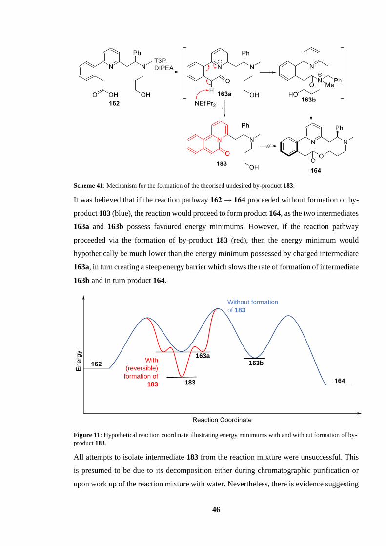
46
Scheme 41: Mechanism for the formation of the theorised undesired by-product 183.
It was believed that if the reaction pathway 162 → 164 proceeded without formation of by-
product 183 (blue), the reaction would proceed to form product 164, as the two intermediates
163a and 163b possess favoured energy minimums. However, if the reaction pathway
proceeded via the formation of by-product 183 (red), then the energy minimum would
hypothetically be much lower than the energy minimum possessed by charged intermediate
163a, in turn creating a steep energy barrier which slows the rate of formation of intermediate
163b and in turn product 164.
Figure 11: Hypothetical reaction coordinate illustrating energy minimums with and without formation of by-
product 183.
All attempts to isolate intermediate 183 from the reaction mixture were unsuccessful. This
is presumed to be due to its decomposition either during chromatographic purification or
upon work up of the reaction mixture with water. Nevertheless, there is evidence suggesting
163a
183
163b
Without formation
of 183
With
(reversible)
formation of
183
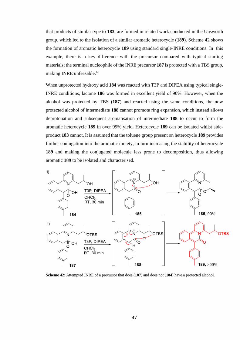
47
that products of similar type to 183, are formed in related work conducted in the Unsworth
group, which led to the isolation of a similar aromatic heterocycle (189). Scheme 42 shows
the formation of aromatic heterocycle 189 using standard single-INRE conditions. In this
example, there is a key difference with the precursor compared with typical starting
materials; the terminal nucleophile of the INRE precursor 187 is protected with a TBS group,
making INRE unfeasable.60
When unprotected hydroxy acid 184 was reacted with T3P and DIPEA using typical single-
INRE conditions, lactone 186 was formed in excellent yield of 90%. However, when the
alcohol was protected by TBS (187) and reacted using the same conditions, the now
protected alcohol of intermediate 188 cannot promote ring expansion, which instead allows
deprotonation and subsequent aromatisation of intermediate 188 to occur to form the
aromatic heterocycle 189 in over 99% yield. Heterocycle 189 can be isolated whilst side-
product 183 cannot. It is assumed that the toluene group present on heterocycle 189 provides
further conjugation into the aromatic moiety, in turn increasing the stability of heterocycle
189 and making the conjugated molecule less prone to decomposition, thus allowing
aromatic 189 to be isolated and characterised.
Scheme 42: Attempted INRE of a precursor that does (187) and does not (184) have a protected alcohol.

48
3.3 Exploration of Aliphatic Precursors
In an attempt to circumvent the formation of side-product 183, we decided to design an
aliphatic linear precursor which could undergo a multi-INRE reaction without the possibility
of a highly conjugated stable intermediate forming. This proposed precursor (190) contains
two tertiary benzylic amines functioning as internal nucleophiles as well as a primary alcohol
group functioning as the terminal nucleophile. Scheme 43 shows the designed aliphatic
precursor 190 and the proposed multi-INRE mechanistic pathway. Thus, the carboxylic acid
of 190 would undergo activation by the coupling agent T3P, in turn activating acid 190,
allowing for the first internal nucleophile (benzylic amine) to attack into the carbonyl to form
cyclic intermediate 191a. The second internal nucleophile (benzylic amine) would then
attack into the same carbonyl, displacing the first internal nucleophile to form the 9-
membered intermediate 191b. Finally, the terminal nucleophile (primary alcohol) would
attack into the carbonyl, displacing the second internal nucleophile before stabilising the
charge via deprotonation to form the saturated ring expanded lactone 192. It was hoped that
the lack of aryl groups in the main carbon backbone would remove the possibility of
aromatisation during the reaction, and hopefully in turn would reduce the formation of any
competing conjugated side-products.
Scheme 43: Proposed multi-INRE mechanism of aliphatic precursor 190 to form aliphatic lactone 192.
We envisaged the synthesis of precursor 192 to procced via repeated SN2 reactions between
alkyl bromides (193) with secondary amines (194) to afford longer alkyl chains containing
primary alcohols (195) which could be converted into alkyl bromides (196) in order to repeat
the sequence. Scheme 44 outlines the general synthetic strategy used. If successful, this
strategy would allow for the synthesis of multiple alkyl precursors of differing lengths from
a single synthetic strategy. It was also hoped that by altering the alkyl chain length between
functional groups and in turn altering the ring size of individual intermediates, greater insight
into the optimum intermediate ring size for multi-INRE reactions would be obtained.
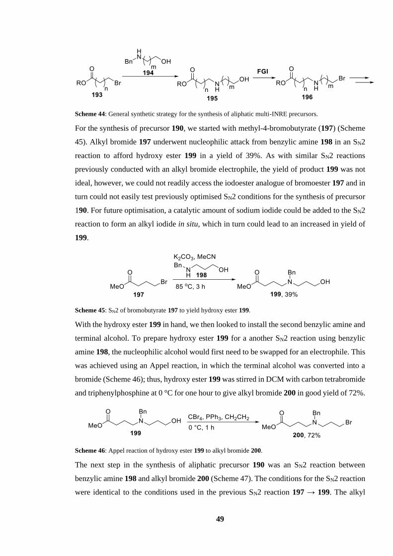
49
Scheme 44: General synthetic strategy for the synthesis of aliphatic multi-INRE precursors.
For the synthesis of precursor 190, we started with methyl-4-bromobutyrate (197) (Scheme
45). Alkyl bromide 197 underwent nucleophilic attack from benzylic amine 198 in an SN2
reaction to afford hydroxy ester 199 in a yield of 39%. As with similar SN2 reactions
previously conducted with an alkyl bromide electrophile, the yield of product 199 was not
ideal, however, we could not readily access the iodoester analogue of bromoester 197 and in
turn could not easily test previously optimised SN2 conditions for the synthesis of precursor
190. For future optimisation, a catalytic amount of sodium iodide could be added to the SN2
reaction to form an alkyl iodide in situ, which in turn could lead to an increased in yield of
199.
Scheme 45: SN2 of bromobutyrate 197 to yield hydroxy ester 199.
With the hydroxy ester 199 in hand, we then looked to install the second benzylic amine and
terminal alcohol. To prepare hydroxy ester 199 for a another SN2 reaction using benzylic
amine 198, the nucleophilic alcohol would first need to be swapped for an electrophile. This
was achieved using an Appel reaction, in which the terminal alcohol was converted into a
bromide (Scheme 46); thus, hydroxy ester 199 was stirred in DCM with carbon tetrabromide
and triphenylphosphine at 0 °C for one hour to give alkyl bromide 200 in good yield of 72%.
Scheme 46: Appel reaction of hydroxy ester 199 to alkyl bromide 200.
The next step in the synthesis of aliphatic precursor 190 was an SN2 reaction between
benzylic amine 198 and alkyl bromide 200 (Scheme 47). The conditions for the SN2 reaction
were identical to the conditions used in the previous SN2 reaction 197 → 199. The alkyl

50
bromide 200 was reacted with 3-(benzylamino)propan-1-ol (198) and potassium carbonate
in acetonitrile at 85 °C for 3 h to afford hydroxy ester 201 in yield of 45%. The yield for this
reaction was not ideal, and could potentially be improved with further optimisation (see
future work); nevertheless, sufficient quantities of hydroxy ester 201 was synthesised to
allow the synthesis of precursor 190 to continue.
Scheme 47: Alkylation of alkyl bromide 200 to yield hydroxy ester 201.
The final step of the synthetic route was hydrolysis of ester 201 to reveal the hydroxy acid
precursor (190) that would undergo the aliphatic multi-INRE reaction. Scheme 48 shows the
hydrolysis of ester 201 using previously identified conditions (182 → 162). Accordingly,
hydroxy ester 201 was vigorously stirred in a solution of water and THF with lithium
hydroxide for 18 h at room temperature to afford hydroxy acid 190 in yield of 40%. As we
would expect the hydrolysis of methyl ester 201 into acid 190 to proceed to completion under
the conditions used, the 40% yield obtained was disappointing. It is assumed that the poor
yield was caused by two key factors. First, impurities carried forward from previous
reactions were removed in a more polar chromatographic purification solvent system (ethyl
acetate and methanol), reducing the isolated mass retrieved. Second, the impurities carried
forward were eluting at similar Rfs to product 190, making separation of product 190 from
side-products via column chromatography more challenging. It is hoped that revising the
synthesis of hydroxy acid 190, the quantity of impurities could be severely reduced.
Scheme 48: Hydrolysis of ester 201 to yield INRE precursor 190.
With the synthesis of linear precursor 190 complete, we now had a synthetic route (albeit
unoptimised) to access both the aliphatic precursor at hand, that could also be applied to
make other aliphatic linear precursors of differing lengths. Scheme 50 shows the synthetic
route for hydroxy acid 190, which has an overall yield of 5% over four steps. As previously
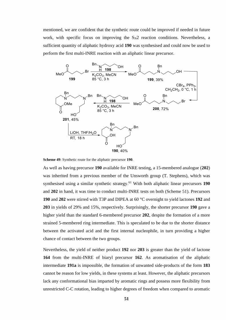
51
mentioned, we are confident that the synthetic route could be improved if needed in future
work, with specific focus on improving the SN2 reaction conditions. Nevertheless, a
sufficient quantity of aliphatic hydroxy acid 190 was synthesised and could now be used to
perform the first multi-INRE reaction with an aliphatic linear precursor.
Scheme 49: Synthetic route for the aliphatic precursor 190.
As well as having precursor 190 available for INRE testing, a 15-membered analogue (202)
was inherited from a previous member of the Unsworth group (T. Stephens), which was
synthesised using a similar synthetic strategy.61 With both aliphatic linear precursors 190
and 202 in hand, it was time to conduct multi-INRE tests on both (Scheme 51). Precursors
190 and 202 were stirred with T3P and DIPEA at 60 °C overnight to yield lactones 192 and
203 in yields of 29% and 15%, respectively. Surprisingly, the shorter precursor 190 gave a
higher yield than the standard 6-membered precursor 202, despite the formation of a more
strained 5-membered ring intermediate. This is speculated to be due to the shorter distance
between the activated acid and the first internal nucleophile, in turn providing a higher
chance of contact between the two groups.
Nevertheless, the yield of neither product 192 nor 203 is greater than the yield of lactone
164 from the multi-INRE of biaryl precursor 162. As aromatisation of the aliphatic
intermediate 191a is impossible, the formation of unwanted side-products of the form 183
cannot be reason for low yields, in these systems at least. However, the aliphatic precursors
lack any conformational bias imparted by aromatic rings and possess more flexibility from
unrestricted C-C rotation, leading to higher degrees of freedom when compared to aromatic
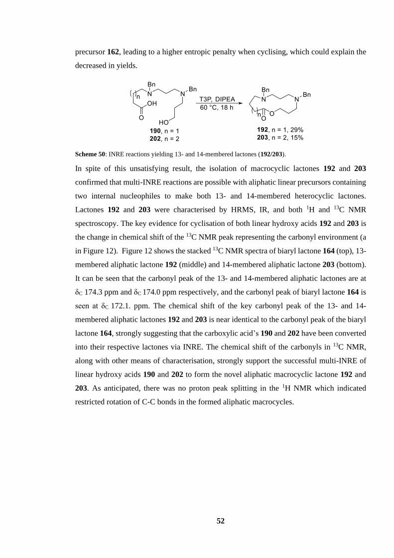
52
precursor 162, leading to a higher entropic penalty when cyclising, which could explain the
decreased in yields.
Scheme 50: INRE reactions yielding 13- and 14-membered lactones (192/203).
In spite of this unsatisfying result, the isolation of macrocyclic lactones 192 and 203
confirmed that multi-INRE reactions are possible with aliphatic linear precursors containing
two internal nucleophiles to make both 13- and 14-membered heterocyclic lactones.
Lactones 192 and 203 were characterised by HRMS, IR, and both 1H and 13C NMR
spectroscopy. The key evidence for cyclisation of both linear hydroxy acids 192 and 203 is
the change in chemical shift of the 13C NMR peak representing the carbonyl environment (a
in Figure 12). Figure 12 shows the stacked 13C NMR spectra of biaryl lactone 164 (top), 13-
membered aliphatic lactone 192 (middle) and 14-membered aliphatic lactone 203 (bottom).
It can be seen that the carbonyl peak of the 13- and 14-membered aliphatic lactones are at
δC 174.3 ppm and δC 174.0 ppm respectively, and the carbonyl peak of biaryl lactone 164 is
seen at δC 172.1. ppm. The chemical shift of the key carbonyl peak of the 13- and 14-
membered aliphatic lactones 192 and 203 is near identical to the carbonyl peak of the biaryl
lactone 164, strongly suggesting that the carboxylic acid’s 190 and 202 have been converted
into their respective lactones via INRE. The chemical shift of the carbonyls in 13C NMR,
along with other means of characterisation, strongly support the successful multi-INRE of
linear hydroxy acids 190 and 202 to form the novel aliphatic macrocyclic lactone 192 and
203. As anticipated, there was no proton peak splitting in the 1H NMR which indicated
restricted rotation of C-C bonds in the formed aliphatic macrocycles.
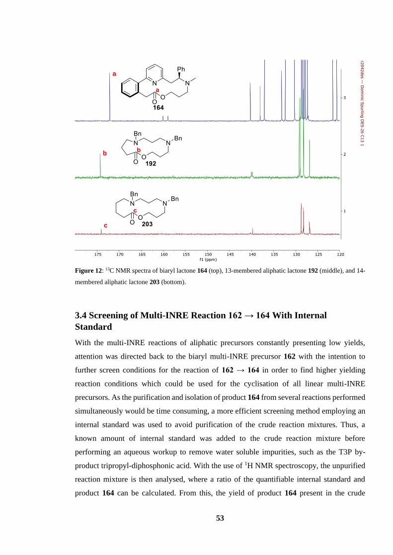
53
Figure 12: 13C NMR spectra of biaryl lactone 164 (top), 13-membered aliphatic lactone 192 (middle), and 14-
membered aliphatic lactone 203 (bottom).
3.4 Screening of Multi-INRE Reaction 162 → 164 With Internal
Standard
With the multi-INRE reactions of aliphatic precursors constantly presenting low yields,
attention was directed back to the biaryl multi-INRE precursor 162 with the intention to
further screen conditions for the reaction of 162 → 164 in order to find higher yielding
reaction conditions which could be used for the cyclisation of all linear multi-INRE
precursors. As the purification and isolation of product 164 from several reactions performed
simultaneously would be time consuming, a more efficient screening method employing an
internal standard was used to avoid purification of the crude reaction mixtures. Thus, a
known amount of internal standard was added to the crude reaction mixture before
performing an aqueous workup to remove water soluble impurities, such as the T3P by-
product tripropyl-diphosphonic acid. With the use of 1H NMR spectroscopy, the unpurified
reaction mixture is then analysed, where a ratio of the quantifiable internal standard and
product 164 can be calculated. From this, the yield of product 164 present in the crude
c
b
a
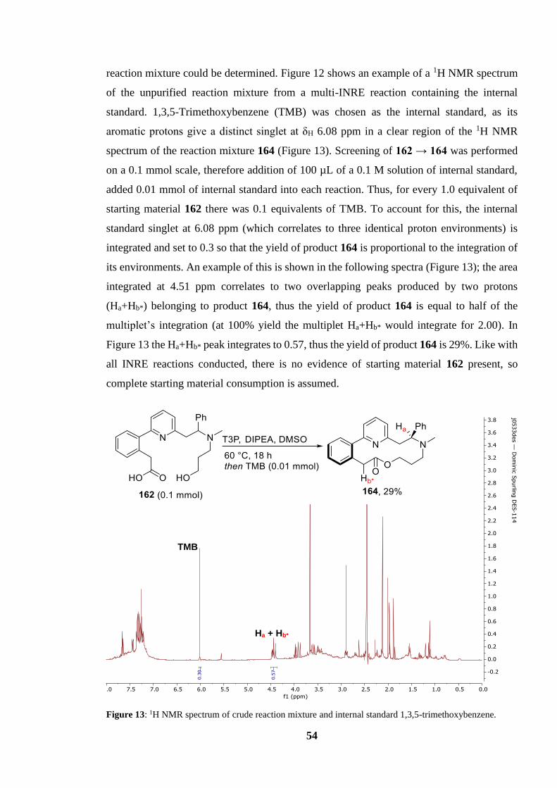
54
reaction mixture could be determined. Figure 12 shows an example of a 1H NMR spectrum
of the unpurified reaction mixture from a multi-INRE reaction containing the internal
standard. 1,3,5-Trimethoxybenzene (TMB) was chosen as the internal standard, as its
aromatic protons give a distinct singlet at δH 6.08 ppm in a clear region of the 1H NMR
spectrum of the reaction mixture 164 (Figure 13). Screening of 162 → 164 was performed
on a 0.1 mmol scale, therefore addition of 100 µL of a 0.1 M solution of internal standard,
added 0.01 mmol of internal standard into each reaction. Thus, for every 1.0 equivalent of
starting material 162 there was 0.1 equivalents of TMB. To account for this, the internal
standard singlet at 6.08 ppm (which correlates to three identical proton environments) is
integrated and set to 0.3 so that the yield of product 164 is proportional to the integration of
its environments. An example of this is shown in the following spectra (Figure 13); the area
integrated at 4.51 ppm correlates to two overlapping peaks produced by two protons
(Ha+Hb*) belonging to product 164, thus the yield of product 164 is equal to half of the
multiplet’s integration (at 100% yield the multiplet Ha+Hb* would integrate for 2.00). In
Figure 13 the Ha+Hb* peak integrates to 0.57, thus the yield of product 164 is 29%. Like with
all INRE reactions conducted, there is no evidence of starting material 162 present, so
complete starting material consumption is assumed.
Figure 13: 1H NMR spectrum of crude reaction mixture and internal standard 1,3,5-trimethoxybenzene.
1
TMB
Ha + Hb*

55
By using this method of high throughput screening, eight reactions could be set up
simultaneously, and analysed relatively quickly, increasing our screening capabilities
considerably. In total, 21 INRE reactions were conducted using this method, as seen in Table
3, with modifications to the temperature, coupling agent and solvent.
Table 3: Screening conditions using internal standard and their respective yield. b Solvent dried out.
Entry Coupling Agent Solvent Temperature / oC Yield / %
1 T3P DMF 60 30
2 EDC DMF 60 15
3 2-Chloro-1-methylpyridinium
iodide
DMF 60 0
4 T3P DMSO 25 29
5 T3P PhMe 25 16
6 T3P THF 25 22
7 T3P MeCN 25 31
8 T3P CHCl3 25 10
9 T3P DMSO 60 29
10 T3P PhMe 60 5
11 T3P THF 60 20
12 T3P CHCl3 60 15
13 T3P DMSO 190 0 b
14 T3P PhMe 110 7
15 T3P THF 66 trace
16 T3P MeCN 82 trace
17 EDC + HOBt DMF 25 72
18 EDC + HOBt DMSO 25 40
19 EDC + HOBt PhMe 25 69
20 EDC +HOBt THF 25 66
21 EDC + HOBt MeCN 25 70
The first modification came from replacing T3P for other coupling agents commonly used
in peptide coupling reactions in an attempt to find a better suited coupling agent. The
coupling agents tested were 1-ethyl-3-(3-dimethylaminopropyl)carbodiimide (EDC) (Entry
1) and 2-chloro-1-methylpyridinium iodide (Entry 2). Disappointingly, when using these
coupling agents the yield of 164 was dramatically reduced, which led us to focus our
attention on changing other variables, such as solvents. Five solvents, DMSO, toluene, THF,
acetonitrile, and chloroform were screened at room temperature, 60 °C, and reflux (Entry 4–

56
16). It was hoped that using a diverse selection of solvents with varying polarities and boiling
points would give further insight into how the reaction proceeded, and in turn would lead to
further optimisation. However, after screening each solvent at the aforementioned
temperatures, none of these solvents proved to be particularly effective, however, multi-
INRE reactions conducted in DMSO and acetonitrile gave yields similar to the multi-INRE
reactions carried out in DMF. The ~30% yield obtained in different polar solvents further
supports the idea that a charged intermediate, such as pyridinium 163a and ammonium 163b
are formed during the reaction. Also, the yield of lactone 164 was reduced when solvents
were heated to reflux (Entry 13–16), indicating that temperatures above 60 °C are
unfavourable for multi-INRE reactions.
EDC was then used once again, but now with the addition of a hydroxybenzotriazole (HOBt)
additive using DMF as the solvent. Pleasingly, this gave a significant increase in yield of
product 164, with an increase in yield from 30% to 72% (Entry 17). The HOBt additive was
tested in combination with other solvents in hope of finding a less toxic alternative which
was more volatile. Pleasingly, a solvent swap to acetonitrile was found to be similarly
successful, and due to easier removal (in view of its volatility) and lower toxicity compared
with DMF, it was retained for future studies.
Scheme 51 shows the optimised conditions; EDC and HOBt (1.5 equivalents), and DIPEA
in acetonitrile (0.1 M) at room temperature for 18 h, as well as the mechanism for carboxylic
acid activation using EDC. The electrophilic carbodiimide 204 was attacked by the
deprotonated carboxylic acid of precursor 162 to give the intermediate 205a. The now more
electrophilic carbonyl of intermediate 205a was then attacked again by the hydroxylamine
of HOBt (206), ejecting a urea by-product and forming the activated acid 205b. The carbonyl
of the activated acid 205b was then attacked by the pyridine internal nucleophile, starting
the multi-INRE cascade which subsequently yields product 164. Pleasingly, we found the
isolated yield (following column chromatography) using these conditions to be 73%, slightly
higher than what was seen using internal standard.
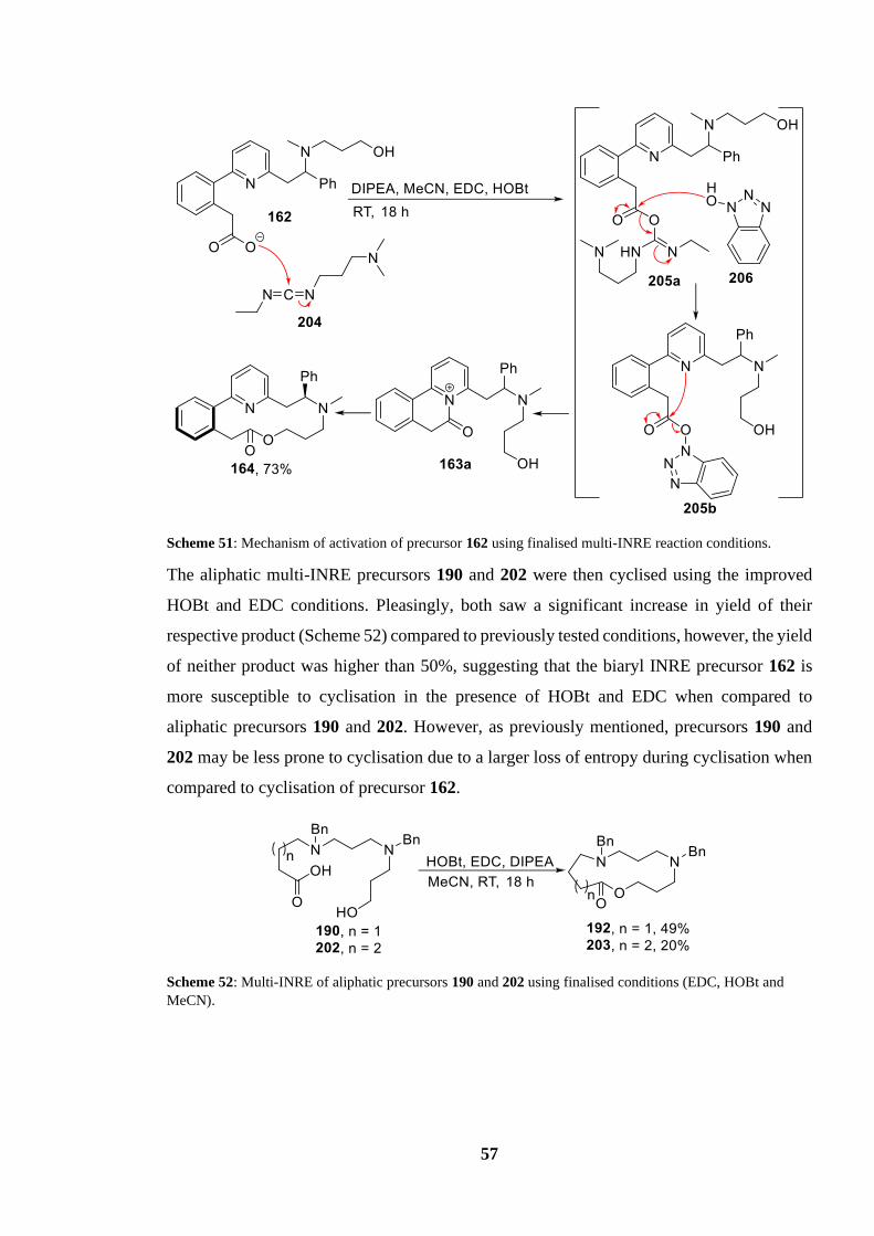
57
Scheme 51: Mechanism of activation of precursor 162 using finalised multi-INRE reaction conditions.
The aliphatic multi-INRE precursors 190 and 202 were then cyclised using the improved
HOBt and EDC conditions. Pleasingly, both saw a significant increase in yield of their
respective product (Scheme 52) compared to previously tested conditions, however, the yield
of neither product was higher than 50%, suggesting that the biaryl INRE precursor 162 is
more susceptible to cyclisation in the presence of HOBt and EDC when compared to
aliphatic precursors 190 and 202. However, as previously mentioned, precursors 190 and
202 may be less prone to cyclisation due to a larger loss of entropy during cyclisation when
compared to cyclisation of precursor 162.
Scheme 52: Multi-INRE of aliphatic precursors 190 and 202 using finalised conditions (EDC, HOBt and
MeCN).

58
3.4 Summary
The yield for the cyclisation of linear precursor 162 into heterocyclic-macrocycle 164 via a
multi-INRE reaction has been raised from the initial 17% to a much more satisfying 73%.
The increase in yield was achieved through the high throughput screening of the INRE
reaction with use of an internal standard. EDC was found to be the optimal coupling reagent
along with an HOBt additive and acetonitrile was the optimal solvent.
A novel aliphatic linear multi-INRE precursor (190) was prepared in a four-step synthesis.
Using aliphatic precursors 190 and 202, novel aliphatic heterocyclic-macrocycles 192 and
203 were synthesised via a multi-INRE in yields of 49% and 20% respectively. Thus, multi-
INRE reactions have proven to be successful when synthesising both 13- and 14-membered
aliphatic heterocyclic-macrocycles.
The possible formation of a conjugated side-product (183) from the multi-INRE of biaryl
precursors has been explored, although no firm conclusions have been made and its role in
the mechanistic pathway is still unclear.

59
Further Exploration of Scope
4.1 Synthetic Targets
With the conditions for multi-INRE reactions finalised, we moved towards exploring what
macrocycles could and could not be made via multi-INRE, giving insight into the limitations
of the multi-INRE reaction. Several precursors and their respective products were designed
in order to investigate factors which could contribute towards the success or limitation of the
INRE reaction (Scheme 53).
The first precursor designed, amino acid 207, possesses an aniline moiety as the terminal
nucleophile. A similar system was envisioned when designing precursor 209, but with the
change of the second internal nucleophile from a tertiary methyl amine to a less nucleophilic
tertiary phenylamine. The third precursor designed, the mono-aryl precursor 211, is near
identical to precursor 162 except with the absence of an aryl group adjacent to the pyridine
internal nucleophile.
Scheme 53: Designed multi-INRE precursors and their respective INRE products.
It was hoped that a synthetic route could be developed for most, if not all, precursors listed
in Scheme 53. Due to complications caused by the SARS-CoV-2 pandemic,62 laboratory
work was abruptly stopped, and many envisioned synthetic routes could not be fully

60
developed and no further INRE reactions could be carried out. Nonetheless, progress to date
on each route is provided.
4.2 Synthesis of a Precursor with Phenylamine Terminal Nucleophile (207)
A full synthetic route was designed for precursor 207. As the carbon framework of precursor
207 is identical to the initial multi-INRE precursor 162, much of the synthetic route to access
precursor 207 is based on the route used to access precursor 162. The main deviation from
the synthetic route to precursor 162 is the alkylation of secondary amine 174 (Scheme 54).
In order to install a phenylamine as the tertiary nucleophile, an SN2 reaction was attempted
using bromo phenylamine 213. Thus, secondary amine 174 was stirred with bromo
phenylamine 213 in acetonitrile with potassium carbonate for 18 h at 85 °C to give the
tertiary amine 214 in yield of 30%.
Scheme 54: Alkylation of secondary amine 174 to give phenylamine 214.
Although the SN2 reaction shown in Scheme 54 was low yielding, a more electrophilic
replacement for bromo phenylamine 213 with a better leaving group (such as iodide) was
unavailable. This is in part due to the unstable nature of reagent 213, which contains both an
electrophilic bromide and nucleophilic phenylamine, which causes reagent 213 to cyclise
slowly over time. Due to the instability of phenylamine 213, it was prepared the day of use
through a separate SN2 reaction (Scheme 55). Aniline (215) underwent a single addition to
dibromopropane (216), which was in large excess (6.0 equivalents), in acetonitrile at reflux
for 3 h to afford bromo phenylamine 213 in a yield of 33%. The secondary amine of product
213 would then undergo an additional SN2 to cyclise and form heterocycle 217 when left for
a prolonged time at room temperature. In view of both the low yield of product 214 and the
instability of reagent 213, this step of the synthetic route to precursor 207 would need to be
revisited and improved in future work.

61
Scheme 55: Synthesis of bromo phenylamine 213 and its subsequent decomposition 213 → 217.
The following steps of the synthetic route towards precursor 207 are near identical to the
final steps towards precursor 162 (Scheme 56). Bromopyridine 214 was coupled to boronic
ester pinacol 181 in a Suzuki-Miyaura cross-coupling reaction with potassium phosphate
and Pd(dppf)Cl2 to afford hydroxy ester 218 in yield of 76%, before subsequently
undergoing hydrolysis with lithium hydroxide to furnish the final precursor 207 in yield of
68%. Pleasingly, both reactions provided their respective product in adequate yield, leading
to no further consideration of reaction optimisation.
Scheme 56: Suzuki-Miyaura coupling and subsequent hydrolysis of bromopyridine 214 to award precursor
207.
Scheme 57 shows all the reactions involved in the synthesis of the linear precursor 207 from
bromomethyl pyridine 173 with an overall yield of 14%. As previously mentioned, there is
room for further optimisation if time had allowed. With the synthesis of precursor 207
complete, we could now test this substrate in a novel multi-INRE precursor using a free
amine as the terminal nucleophile, which in turn could be used for the synthesis of the first
macrocyclic lactam containing multiple internal nucleophiles (208) via multi-INRE.
Because of the SARS-CoV-2 pandemic, this reaction has not yet been tested.

62
Scheme 57: Synthesis route to linear precursor 207.
4.3 Work Towards a Precursor with Phenylamine Internal Nucleophile
(210)
Considerable progress towards a linear precursor containing a phenylamine internal
nucleophile (210) was also made. The first synthetic route to precursor 210 attempted to
alkylate phenylamine 221 with an alkyl halide, similar to previous SN2 attempts shown in
Scheme 33 and Scheme 54. It was initially hoped that bromomethyl pyridine 173 could be
reacted with a phenyl imine analogue similar to 172, however, no such imine was
commercially available. Instead, synthesis of phenylamine 221 was achieved via the
lithiation-trapping of bromomethyl pyridine 173 and its subsequent reductive amination,
using conditions previously reported in the literature (Scheme 58).57 Bromomethyl pyridine
173 was deprotonated by LDA before subsequently attacking into N-methoxy-N-
methylacetamide 219, consequently undergoing nucleophilic substitution to give ketone 220
in a yield of 84%. Ketone 220 then underwent reductive amination with aniline using the
reducing agent sodium triacetoxyborohydride (STAB) to afford phenylamine 221 in a yield
of 88%.

63
Scheme 58: Lithiation-trapping and subsequent reductive amination of bromomethyl pyridine 173 to afford
phenylamine 221.
With a large quantity of phenylamine 221 at our disposal, alkylation was attempted using a
variety of alkyl halides. Scheme 59 shows all the alkylation reactions attempted in the hope
of synthesising alcohol 222. Using typical SN2 conditions, alkylation of phenylamine was
attempted with electrophilic reagents including chloropropanol 175, bromopropanol 177,
and iodopropanol 178. These alkylation reactions were all unsuccessful, with none of
product 222 identified from either TLC or the 1H NMR spectrum of the unpurified reaction
mixture, and a large quantity of unreacted starting material 221 was observed in the reaction
mixtures. This is likely due to the fact that the aniline group of 221 is much less nucleophilic
than analogous aliphatic amines used in other systems, due to delocalisation into the bonded
phenyl group.
Scheme 59: Attempted alkylation of phenylamine 221 using alkyl halides 175, 177 and 178.
With realisation that phenylamine 221 is unable to undergo an SN2 reaction, an alternative
strategy was conceived, where ketone 220 would undergo reductive amination with a
phenylamine to give tertiary amine 222 (Scheme 60). The first reductive amination
attempted was with phenylamine 223, acetic acid, and sodium triacetoxyborohydride
(STAB) in 1,2-dichloroethene (DCE) overnight at room temperature. Disappointingly, this
did not yield product 222.
Scheme 60: Attempted reductive amination of ketone 220 with phenylamine 223.

64
However, an uncharacterised side-product was identified by HRMS. Although full data was
not obtained to confirm this, it was speculated that the alcohol present in phenylamine 223
was acting as a competing nucleophile, in turn attacking ketone 220 to produce a hemiaminal
species (225) (Scheme 61). Thus, the alcohol present on phenylamine 223 could have
attacked into the protonated carbonyl of ketone 220 to give the hemiketal intermediate 224a,
which would then eject water via condensation to give intermediate 224b that could be
attacked once more by the secondary phenylamine to cyclise to give hemiaminal 225.
Scheme 61: Proposed mechanistic route for the formation of hemiaminal side-product 225.
To prevent possible interference from a competing nucleophile, the alcohol of 223 was
protected using TBS, to give reagent 226 (Scheme 62). However, when reductive amination
of 220 was attempted using protected phenylamine 226, the 1H NMR spectrum and TLC of
the unpurified reaction mixture showed no evidence of product 227 being formed.
Scheme 62: Attempted reductive amination of ketone 220 with protected alcohol 226.
A final reductive amination reaction was attempted in hope of synthesising a precursor
possessing a phenylamine internal nucleophile. It was anticipated that a more electrophilic
carbonyl, such as an aldehyde, would be more susceptible to attack from phenylamine 210,
and in turn would allow for reductive amination to proceed. Scheme 63 shows the in situ
synthesis of the aldehyde 228 from bromomethyl pyridine 173, followed by the subsequent
reductive amination of aldehyde 228 with phenylamine 223. Thus, bromomethyl pyridine
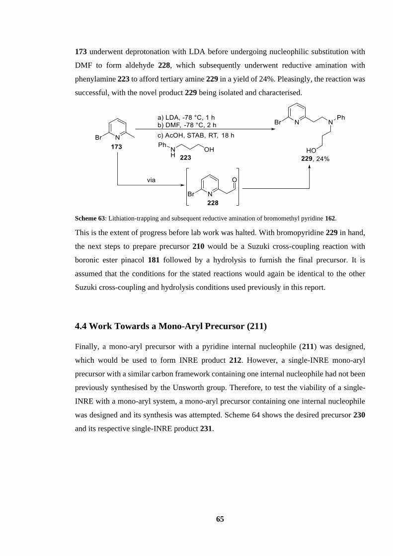
65
173 underwent deprotonation with LDA before undergoing nucleophilic substitution with
DMF to form aldehyde 228, which subsequently underwent reductive amination with
phenylamine 223 to afford tertiary amine 229 in a yield of 24%. Pleasingly, the reaction was
successful, with the novel product 229 being isolated and characterised.
Scheme 63: Lithiation-trapping and subsequent reductive amination of bromomethyl pyridine 162.
This is the extent of progress before lab work was halted. With bromopyridine 229 in hand,
the next steps to prepare precursor 210 would be a Suzuki cross-coupling reaction with
boronic ester pinacol 181 followed by a hydrolysis to furnish the final precursor. It is
assumed that the conditions for the stated reactions would again be identical to the other
Suzuki cross-coupling and hydrolysis conditions used previously in this report.
4.4 Work Towards a Mono-Aryl Precursor (211)
Finally, a mono-aryl precursor with a pyridine internal nucleophile (211) was designed,
which would be used to form INRE product 212. However, a single-INRE mono-aryl
precursor with a similar carbon framework containing one internal nucleophile had not been
previously synthesised by the Unsworth group. Therefore, to test the viability of a single-
INRE with a mono-aryl system, a mono-aryl precursor containing one internal nucleophile
was designed and its synthesis was attempted. Scheme 64 shows the desired precursor 230
and its respective single-INRE product 231.
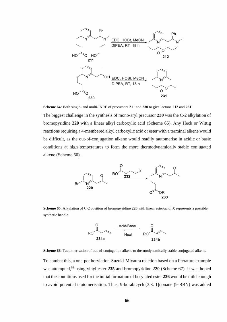
66
Scheme 64: Both single- and multi-INRE of precursors 211 and 230 to give lactone 212 and 231.
The biggest challenge in the synthesis of mono-aryl precursor 230 was the C-2 alkylation of
bromopyridine 220 with a linear alkyl carboxylic acid (Scheme 65). Any Heck or Wittig
reactions requiring a 4-membered alkyl carboxylic acid or ester with a terminal alkene would
be difficult, as the out-of-conjugation alkene would readily tautomerise in acidic or basic
conditions at high temperatures to form the more thermodynamically stable conjugated
alkene (Scheme 66).
Scheme 65: Alkylation of C-2 position of bromopyridine 220 with linear ester/acid. X represents a possible
synthetic handle.
Scheme 66: Tautomerisation of out-of-conjugation alkene to thermodynamically stable conjugated alkene.
To combat this, a one-pot borylation-Suzuki-Miyaura reaction based on a literature example
was attempted,63 using vinyl ester 235 and bromopyridine 220 (Scheme 67). It was hoped
that the conditions used for the initial formation of borylated ester 236 would be mild enough
to avoid potential tautomerisation. Thus, 9-borabicyclo[3.3. 1]nonane (9-BBN) was added
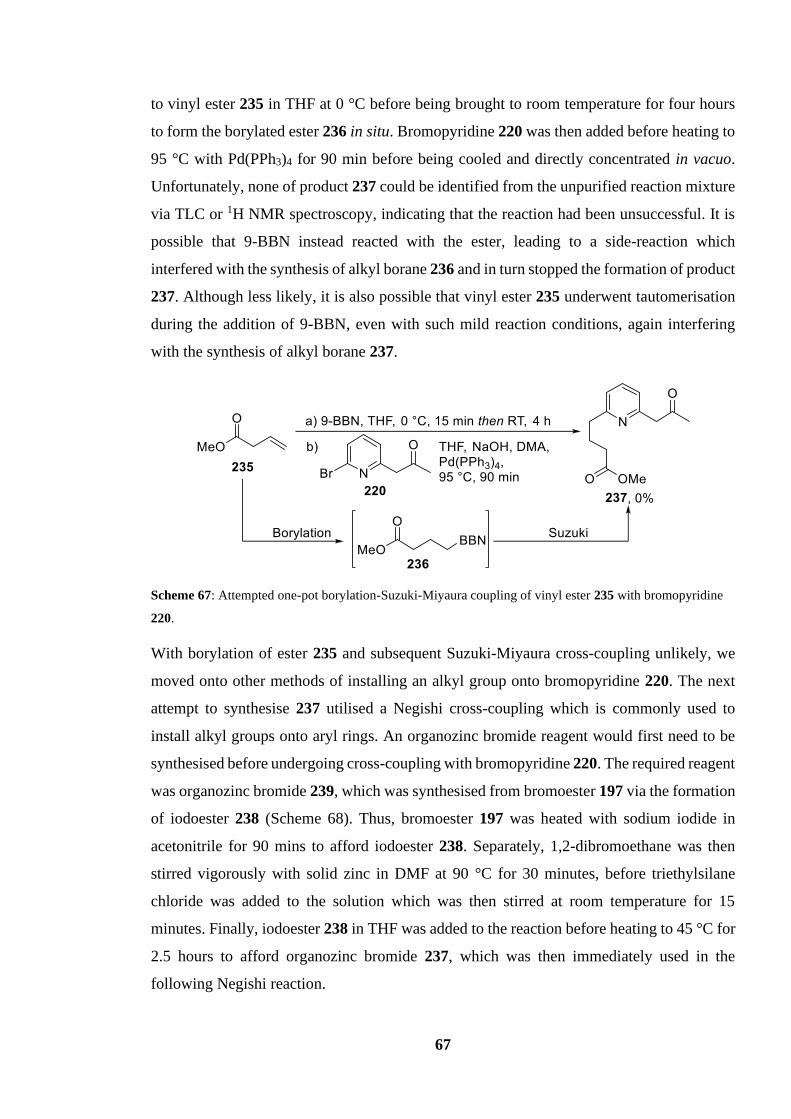
67
to vinyl ester 235 in THF at 0 °C before being brought to room temperature for four hours
to form the borylated ester 236 in situ. Bromopyridine 220 was then added before heating to
95 °C with Pd(PPh3)4 for 90 min before being cooled and directly concentrated in vacuo.
Unfortunately, none of product 237 could be identified from the unpurified reaction mixture
via TLC or 1H NMR spectroscopy, indicating that the reaction had been unsuccessful. It is
possible that 9-BBN instead reacted with the ester, leading to a side-reaction which
interfered with the synthesis of alkyl borane 236 and in turn stopped the formation of product
237. Although less likely, it is also possible that vinyl ester 235 underwent tautomerisation
during the addition of 9-BBN, even with such mild reaction conditions, again interfering
with the synthesis of alkyl borane 237.
Scheme 67: Attempted one-pot borylation-Suzuki-Miyaura coupling of vinyl ester 235 with bromopyridine
220.
With borylation of ester 235 and subsequent Suzuki-Miyaura cross-coupling unlikely, we
moved onto other methods of installing an alkyl group onto bromopyridine 220. The next
attempt to synthesise 237 utilised a Negishi cross-coupling which is commonly used to
install alkyl groups onto aryl rings. An organozinc bromide reagent would first need to be
synthesised before undergoing cross-coupling with bromopyridine 220. The required reagent
was organozinc bromide 239, which was synthesised from bromoester 197 via the formation
of iodoester 238 (Scheme 68). Thus, bromoester 197 was heated with sodium iodide in
acetonitrile for 90 mins to afford iodoester 238. Separately, 1,2-dibromoethane was then
stirred vigorously with solid zinc in DMF at 90 °C for 30 minutes, before triethylsilane
chloride was added to the solution which was then stirred at room temperature for 15
minutes. Finally, iodoester 238 in THF was added to the reaction before heating to 45 °C for
2.5 hours to afford organozinc bromide 237, which was then immediately used in the
following Negishi reaction.

68
Scheme 68: Formation of organozinc bromide 239 from bromo ester 197.
The organozinc product 239 was taken forward in solution to react with bromopyridine 220
in a Negishi cross-coupling reaction (Scheme 69). Bromopyridine 220 was stirred with
organozinc bromide 239 and Pd(PPh3)2Cl2 in THF at reflux for 4 hours to furnish keto-ester
237 in an isolated yield of 33%. Although we were pleased that some of the desired product
has been formed, 1H NMR spectroscopy and TLC analysis of the unpurified reaction mixture
identified a large quantity of starting material still present, accounting for the modest yield
of product 237. One possible solution which could increase the amount of starting material
conversion, and in turn increase the yield of product 223, would be to leave the reaction to
reflux overnight.
Scheme 69: Negishi cross-coupling of bromopyridine 220 with organozinc bromide 239.
With keto-ester 237 synthesised, the rest of the synthetic route towards precursor 230 would
only require two final steps, a reduction of the ketone to an alcohol followed by a hydrolysis
of the methyl ester to give the acid. Similar compounds have been hydrolysed and reduced
in the literature,57 which would likely allow for an unproblematic synthesis of precursor 230
in future work.

69
4.5 Summary
A novel linear multi-INRE precursor containing a phenylamine terminal nucleophile (207)
was synthesised over four steps and can now be tested in a multi-INRE reaction. Two other
novel multi-INRE precursors were also designed; a linear multi-INRE precursor containing
a phenylamine internal nucleophile (210) and a linear single-INRE mono-aryl precursor
(288). Considerable progress has also been made towards a synthetic route to access the two
aforementioned precursors.

70
Future Work
5.1 Short-Term Objectives
As previously stated, the SARS-CoV-2 pandemic abruptly halted all lab work prematurely.62
As a result of the pandemic many short-term objectives were left unfinished, but we predict
that they could be completed quickly and would provide much insight into the multi-INRE
reaction. The most straightforward of these short-term objectives is conducting INRE tests
on all synthesised precursors using the best conditions: HOBt, EDC, MeCN, DIPEA, 25 °C
for 18 h (Scheme 70). If the optimised conditions are successful with the system shown in
Scheme 70 it would suggest that the finalised conditions would be well suited for use in
future multi-INRE reactions using novel linear precursors containing several internal
nucleophiles.
Scheme 70: Cyclisation of precursor 207 via INRE using finalised conditions.
Another short-term objective is the synthesis of the phenylamine internal nucleophile
precursor 209 and the mono-aryl single-INRE precursor 230 as well as forming their
respective INRE products using the finalised conditions. Scheme 71 shows the completion
of the synthetic route to build precursor 209 from previously synthesised tertiary amine 229.
Thus, tertiary amine 229 would undergo a Suzuki-Miyaura cross-coupling reaction with
boronic ester pinacol 181 to afford hydroxy ester 240 before undergoing hydrolysis to
generate hydroxy acid 209. Hydroxy acid 209 could then undergo cyclisation via a multi-
INRE reaction using EDC and HOBt to give lactone 210. As all reactions shown in Scheme
71 are based on previous conditions found in the literature,57 the reactions would be
hopefully be unproblematic and could be carried out in an efficient manner.

71
Scheme 71: Synthesis of precursor 209 from tertiary amine 229 and subsequent INRE to award lactone 210.
Scheme 72 shows the steps necessary to complete the synthesis of precursor 230. Reduction
of keto-ester 237 using sodium borohydride should furnish hydroxy ester 241 which could
then undergo hydrolysis to give hydroxy acid 230. Hydroxy acid 230 could then undergo
cyclisation via INRE to yield lactone 231. Again, all steps use conditions reported in the
literature for the synthesis of near identical analogues, therefore the synthesis of precursor
230 should be unproblematic. If formation of lactone 231 via INRE of hydroxy acid 230 is
successful, work could be then focus towards preparing the mono-aryl precursor with two
internal nucleophiles 211.
Scheme 72: Synthesis of precursor 230 from keto-ester 237 and subsequent INRE to award lactone 231.

72
5.2 Long-Term Objectives
There are also many long-term objectives which could build upon the foundations achieved
so far in this project. The most apparent would be further exploration of scope via the
synthesis of a diverse array of linear multi-INRE precursors. The easiest would be the
synthesis of precursor 211, as again most of the steps used to build the precursor have been
reported in the synthesis of previous multi-INRE precursors in this report. Scheme 73 shows
the synthetic route which could potentially be used to make precursor 211 from
bromopyridine 176, and the subsequent INRE reaction. Thus, bromopyridine 176 would
undergo a Negishi cross-coupling with organozinc bromide 239 to give hydroxy ester 242,
which could then be hydrolysed to give precursor 211. Finally, hydroxy acid 211 could
undergo cyclisation via a multi-INRE reaction using the finalised conditions to furnish the
14-membered lactone 212.
Scheme 73: Synthesis of precursor 211 from bromopyridine 176 and subsequent INRE to award lactone 212.
To further build on the work done in this report, additional optimisation of previous synthetic
routes would allow for streamlined syntheses of both multi-INRE precursors which have
been previously made, and also structurally similar novel analogues, in turn making future
substrate scope studies easier. One such route which could be optimised is the synthesis of
saturated alkyl precursors, such as aliphatic hydroxy acid 190. Optimisation could be
achieved through the synthesis of an alternative electrophilic reagent that possesses a
different leaving group, which could in turn lead to higher yielding SN2 reactions. Scheme
74 outlines one strategy which could potentially increase the efficiency of the synthetic route

73
and in turn increase the yield of precursor 190. Scheme 74 shows the tosylation of alcohol
199 with tosyl chloride to give the electrophilic alkyl tosylate 243 which could then undergo
SN2 with benzylic amine 198 to award hydroxy ester 201. It is hoped that an SN2 reaction
between benzylic amine 198 and tosylate 243 would allow for a higher yield of hydroxy acid
201 compared to an SN2 reaction with its bromide counterpart 200.
Scheme 74: Alternative route for synthesis of hydroxy ester 201; tosylation of alcohol 199 followed by an
SN2 reaction with benzylic amine 198.
This alternative strategy can also be employed in the synthesis of the phenylamine precursor
207. Scheme 74 shows the synthesis of secondary phenylamine 214 from alcohol 176. Rather
than performing an SN2 reaction between secondary amine 174 and bromo phenylamine 213,
the synthetic method shown below instead start from alcohol 176. Scheme 75 shows the
formation of tosylate 244 from alcohol 176 and the subsequent SN2 reaction with aniline to
give phenylamine 214. This strategy would avoid the use of the unstable reagent bromo
phenylamine 213, streamlining the synthetic route and potentially increasing the yield of
phenylamine 214.
Scheme 75: Alternative route for synthesis of phenylamine 214; tosylation of alcohol 176 followed by an
SN2 reaction with aniline.
A key step for the synthetic route of biaryl precursors is the synthesis and subsequent cross-
coupling of boronic pinacol ester 181. However, as previously stated, the purification of this
compound is difficult due to the susceptibility of boronic esters to decompose on silica.64 A
potentially simple solution to this problem would be to purify the boronic ester 181 crude
reaction mixture using aluminium oxide column chromatography. It is hoped that boronic
pinacol ester 181 would be stable in the presence of aluminium oxide, in turn decreasing the
rate of degradation and increasing the retrieval of isolated boronic pinacol ester 181.

74
Finally, a number of novel linear precursors could be developed and subsequently cyclised
via INRE in order to explore the scope and limitations of multi-INRE. Scheme 76 shows
variety of designed precursors and their respective products. One designed precursor could
contain two different heteroatoms that both function as internal nucleophiles (225). If the
subsequent INRE reaction 245 → 246 was successful, it would prove that INRE is possible
with heterocyclic linear precursors containing different heteroatoms acting as internal
nucleophiles, which could lead to further exploration of other nucleophilic heteroatoms such
as phosphorous. Designing precursors which have “swapped” the positions of internal
nucleophiles in the linear chain would provide insight into the importance of the order of
internal nucleophiles. An example is hydroxy acid 247, which structurally is similar to
precursor 162, however, the pyridine and tertiary amine internal nucleophiles have
“swapped” their positions in the linear carbon chain. If the yield of reaction 247 → 248 is
significantly lower or higher than the yield of the reaction 162 → 164, it could be concluded
that the success of a multi-INRE reaction is determined not only by what internal
nucleophiles are used, but also where the internal nucleophiles appear in the linear carbon
chain relative to the carboxylic acid.
A precursor containing three internal nucleophiles could be designed (249). If INRE is
possible with such a precursor (249) it would not only allow for the synthesis of even larger
heterocyclic macrocycles from linear precursors but would suggest that INRE could
hypothetically be used to build macrocycles of impressive sizes with numerous internal
nucleophiles. Finally, atroposelectivity could be explored further, by designing precursors
which possessed chiral centres adjacent to both nucleophiles, such as precursor 251. If the
yield of 251 is significantly higher or lower than the yield of 162→164 it would give further
insight into how the multi-INRE mechanistic pathway proceeds.

75
Scheme 76: Potential INRE precursors and their respective ring expanded products.
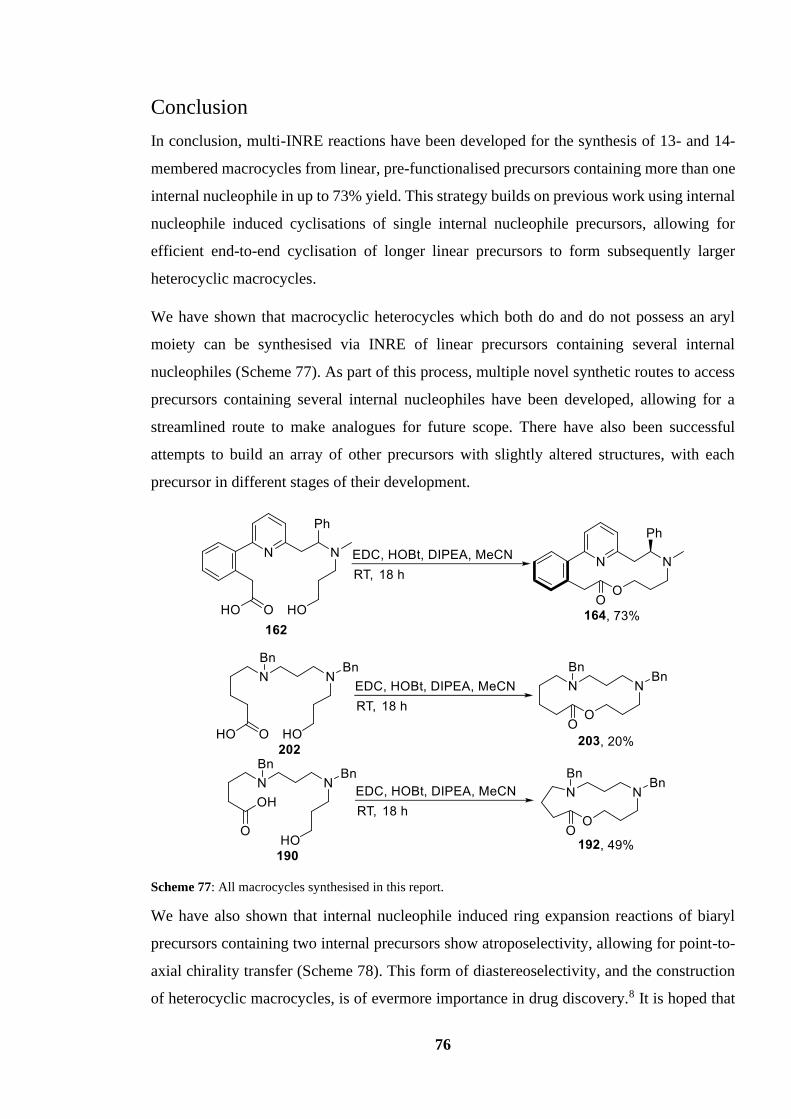
76
Conclusion
In conclusion, multi-INRE reactions have been developed for the synthesis of 13- and 14-
membered macrocycles from linear, pre-functionalised precursors containing more than one
internal nucleophile in up to 73% yield. This strategy builds on previous work using internal
nucleophile induced cyclisations of single internal nucleophile precursors, allowing for
efficient end-to-end cyclisation of longer linear precursors to form subsequently larger
heterocyclic macrocycles.
We have shown that macrocyclic heterocycles which both do and do not possess an aryl
moiety can be synthesised via INRE of linear precursors containing several internal
nucleophiles (Scheme 77). As part of this process, multiple novel synthetic routes to access
precursors containing several internal nucleophiles have been developed, allowing for a
streamlined route to make analogues for future scope. There have also been successful
attempts to build an array of other precursors with slightly altered structures, with each
precursor in different stages of their development.
Scheme 77: All macrocycles synthesised in this report.
We have also shown that internal nucleophile induced ring expansion reactions of biaryl
precursors containing two internal precursors show atroposelectivity, allowing for point-to-
axial chirality transfer (Scheme 78). This form of diastereoselectivity, and the construction
of heterocyclic macrocycles, is of evermore importance in drug discovery.8 It is hoped that

77
the development of INRE shown in this work has allowed for INRE to become a more
reliable and practical tool for the synthesis of important bioactive macrocycles via the
internal nucleophile ring expansion of pre-functionalised linear precursors.
Scheme 78: Atroposelectivity of INRE of precursors containing two internal precursors.
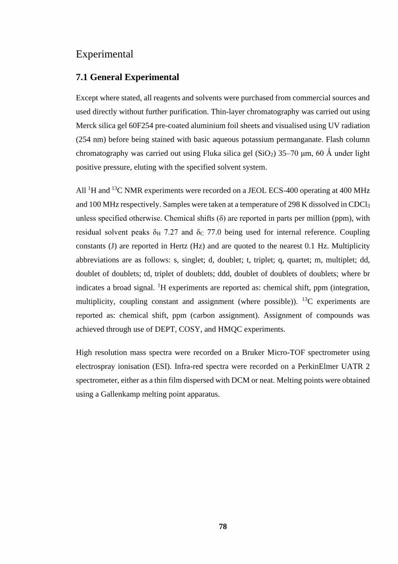
78
Experimental
7.1 General Experimental
Except where stated, all reagents and solvents were purchased from commercial sources and
used directly without further purification. Thin-layer chromatography was carried out using
Merck silica gel 60F254 pre-coated aluminium foil sheets and visualised using UV radiation
(254 nm) before being stained with basic aqueous potassium permanganate. Flash column
chromatography was carried out using Fluka silica gel (SiO2) 35–70 μm, 60 Ǻ under light
positive pressure, eluting with the specified solvent system.
All 1H and 13C NMR experiments were recorded on a JEOL ECS-400 operating at 400 MHz
and 100 MHz respectively. Samples were taken at a temperature of 298 K dissolved in CDCl3
unless specified otherwise. Chemical shifts (δ) are reported in parts per million (ppm), with
residual solvent peaks δH 7.27 and δC 77.0 being used for internal reference. Coupling
constants (J) are reported in Hertz (Hz) and are quoted to the nearest 0.1 Hz. Multiplicity
abbreviations are as follows: s, singlet; d, doublet; t, triplet; q, quartet; m, multiplet; dd,
doublet of doublets; td, triplet of doublets; ddd, doublet of doublets of doublets; where br
indicates a broad signal. 1H experiments are reported as: chemical shift, ppm (integration,
multiplicity, coupling constant and assignment (where possible)). 13C experiments are
reported as: chemical shift, ppm (carbon assignment). Assignment of compounds was
achieved through use of DEPT, COSY, and HMQC experiments.
High resolution mass spectra were recorded on a Bruker Micro-TOF spectrometer using
electrospray ionisation (ESI). Infra-red spectra were recorded on a PerkinElmer UATR 2
spectrometer, either as a thin film dispersed with DCM or neat. Melting points were obtained
using a Gallenkamp melting point apparatus.

79
7.2 List of Experimental Procedures and Characterisations
2-(6-Bromopyridin-2-yl)-N-methyl-1-phenylethan-1-amine (174)
N,N-Diisopropylamine (4.35 mL, 35.1 mmol) was dissolved in THF (175 mL) and cooled to
0 ⁰C before n-BuLi (2.5 M solution in hexanes, 14.0 mL, 35.1 mmol) was added dropwise
and stirred for 30 mins. The LDA solution was then cooled to −78 °C, where 2-bromo-6-
methylpyridine (173) (1.98 mL, 17.5 mmol) was added dropwise and stirred for 1 h. N-
Benzylidenemethylamine (4.35 mL, 35.1 mmol) was added and stirred for a further 2 h at
−78 °C before slowly warming to RT. The solution was then quenched with sat. aq. NH4Cl
(150 mL) and extracted with ethyl acetate (3 × 100 mL) and washed with brine (150 mL).
The combined organic extracts were dried over MgSO4, filtered and removed in vacuo.
Purification by flash column chromatography (SiO2, 5% methanol in ethyl acetate) afforded
the title compound as a yellow oil (3.82 g, 81%); Rf. 0.23 (5% methanol in ethyl acetate); δH
(400 MHz, CDCl3) 7.35–7.27 (7H, m, ArH), 6.86 (1H, d, J = 7.0 Hz, ArH), 3.98 (1H, dd, J
= 8.4, 6.1 Hz, CH2CHNMe), 3.12 (1H, dd, J = 13.7, 6.1 Hz, CCHH′CHPh), 3.01 (1H, dd, J
= 13.7, 8.4 Hz, CCHH′CHPh), 2.25 (3H, s, NHCH3), 1.68–1.65 (1H, br s, NH).
Spectroscopic data matched those reported in the literature.57
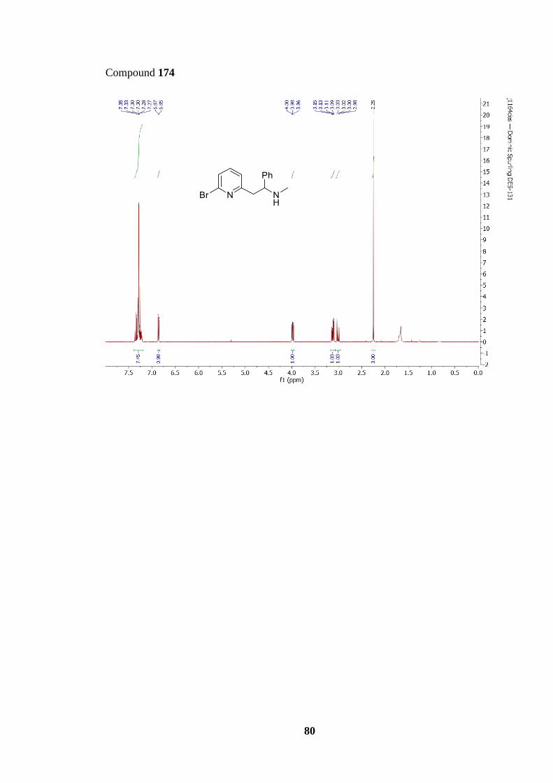
80
Compound 174
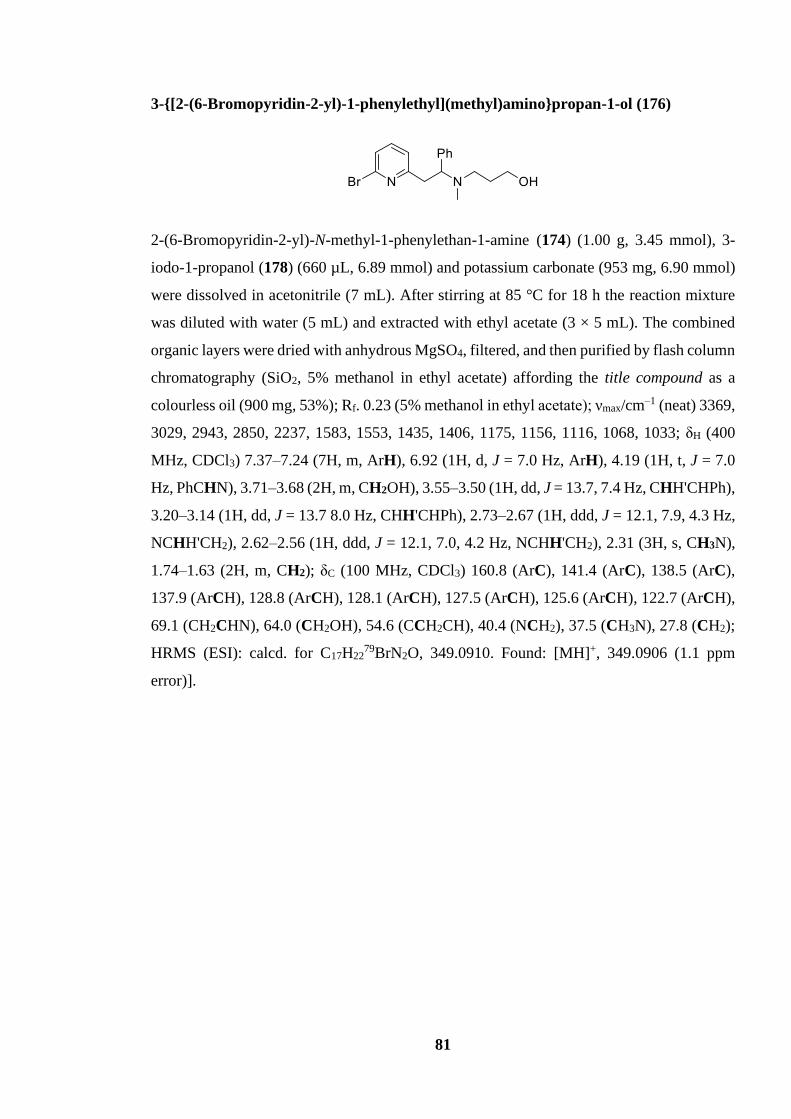
81
3-{[2-(6-Bromopyridin-2-yl)-1-phenylethyl](methyl)amino}propan-1-ol (176)
2-(6-Bromopyridin-2-yl)-N-methyl-1-phenylethan-1-amine (174) (1.00 g, 3.45 mmol), 3-
iodo-1-propanol (178) (660 µL, 6.89 mmol) and potassium carbonate (953 mg, 6.90 mmol)
were dissolved in acetonitrile (7 mL). After stirring at 85 °C for 18 h the reaction mixture
was diluted with water (5 mL) and extracted with ethyl acetate (3 × 5 mL). The combined
organic layers were dried with anhydrous MgSO4, filtered, and then purified by flash column
chromatography (SiO2, 5% methanol in ethyl acetate) affording the title compound as a
colourless oil (900 mg, 53%); Rf. 0.23 (5% methanol in ethyl acetate); νmax/cm–1 (neat) 3369,
3029, 2943, 2850, 2237, 1583, 1553, 1435, 1406, 1175, 1156, 1116, 1068, 1033; δH (400
MHz, CDCl3) 7.37–7.24 (7H, m, ArH), 6.92 (1H, d, J = 7.0 Hz, ArH), 4.19 (1H, t, J = 7.0
Hz, PhCHN), 3.71–3.68 (2H, m, CH2OH), 3.55–3.50 (1H, dd, J = 13.7, 7.4 Hz, CHH'CHPh),
3.20–3.14 (1H, dd, J = 13.7 8.0 Hz, CHH'CHPh), 2.73–2.67 (1H, ddd, J = 12.1, 7.9, 4.3 Hz,
NCHH'CH2), 2.62–2.56 (1H, ddd, J = 12.1, 7.0, 4.2 Hz, NCHH'CH2), 2.31 (3H, s, CH3N),
1.74–1.63 (2H, m, CH2); δC (100 MHz, CDCl3) 160.8 (ArC), 141.4 (ArC), 138.5 (ArC),
137.9 (ArCH), 128.8 (ArCH), 128.1 (ArCH), 127.5 (ArCH), 125.6 (ArCH), 122.7 (ArCH),
69.1 (CH2CHN), 64.0 (CH2OH), 54.6 (CCH2CH), 40.4 (NCH2), 37.5 (CH3N), 27.8 (CH2);
HRMS (ESI): calcd. for C17H2279BrN2O, 349.0910. Found: [MH]+, 349.0906 (1.1 ppm
error)].
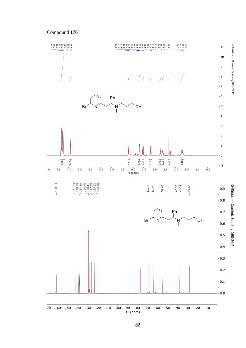
82
Compound 176

83
Methyl 2-(2-bromophenyl)acetate (180)
To a stirring solution of 2-(2-bromophenyl)acetic acid (179) (6.00 g, 28.0 mmol) in methanol
(60 mL) was added concentrated sulfuric acid (1.20 mL) and the resulting solution was
refluxed for 90 mins. After cooling to RT, the reaction was quenched with water (40 mL)
and extracted with diethyl ether (3 × 50 mL). The organic extract was washed with sat. aq.
brine (40 mL), dried over anhydrous MgSO4, filtered and concentrated in vacuo to afford
the title compound as a clear oil (6.33 g, 99%); δH (400 MHz, CDCl3) 7.57 (1H, d, J = 8.2
Hz, ArH), 7.30−7.26 (2H, m, ArH), 7.19–7.12 (1H, m, ArH), 3.81 (2H, s, CH2), 3.72 (3H,
s, CH3).
Spectroscopic data matched those reported in the literature.65
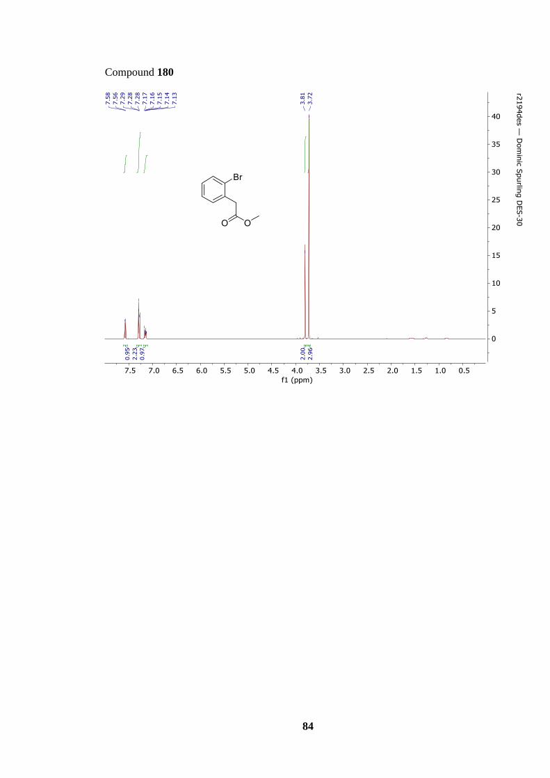
84
Compound 180

85
Methyl 2-(2-(4,4,5,5-tetramethyl-1,3,2-dioxaborolan-2-yl)phenyl)acetate (181)
To a stirring solution of methyl 2-(2-bromophenyl)acetate (180) (2.05 g, 8.98 mmol) in 1,4-
dioxane (36 mL), was added bis(pinacalato)diboron (2.51 g, 9.88 mmol), potassium acetate
(3.35 g, 34.1 mmol) and PdCl2(dppf)·CH2Cl2 (367 mg, 450 µmol). The reaction mixture was
flushed with argon and heated under reflux for 18 h. The reaction mixture was quenched
with water (40 mL) and extracted with diethyl ether (3 × 30 mL). The organic extract was
washed with sat. brine (30 mL), dried over anhydrous MgSO4, filtered and concentrated in
vacuo. Purification via silica gel chromatography (10% hexane in dichloromethane) yielded
the pure product as an off-white solid (1.40 g, 56%); δH (400 MHz, CDCl3) 7.83 (1H, d, J =
7.6 Hz, ArH), 7.40−7.37 (1H, m, ArH), 7.29−7.25 (1H, m, ArH), 7.19 (1H, d, J = 7.5 Hz,
ArH), 3.98 (2H, s, CH2), 3.66 (3H, s, OCH3), 1.32 (12H, s, 4 × CH3).
Spectroscopic data matched those reported in the literature.66

86
Compound 181

87
Methyl 2-[2-(6-{2-[(3-hydroxypropyl)(methyl)amino]-2-phenylethyl}pyridin-2-
yl)phenyl]acetate (182)
3-{[2-(6-Bromopyridin-2-yl)-1-phenylethyl](methyl)amino}propan-1-ol (176) (683 mg,
1.96 mmol), methyl 2-(2-(4,4,5,5-tetramethyl-1,3,2-dioxaborolan-2-yl)phenyl) acetate (181)
(813 mg, 2.94 mmol), potassium phosphate (833 mg, 3.92 mmol) and PdCl2(dppf)·CH2Cl2
(80.0 mg, 89.0 µmol) were charged into an round bottom flask purged with nitrogen. THF
(20 mL) and de-ionised water (178 µL, 9.81 mmol) were added and heated to 80 °C, at
reflux, for 18 h. Upon completion the solution was cooled to room temperature, diluted with
water (15 mL), extracted with ethyl acetate (3 × 20 mL) and washed with sat. brine (10 mL).
The combined organic extracts were dried over MgSO4, filtered, and removed in vacuo.
Purification by flash column chromatography (SiO2, 10% methanol in ethyl acetate) afforded
the title compound as a brown oil (713 mg, 87%); Rf. 0.38 (10% methanol in ethyl acetate);
νmax/cm–1 (neat) 3367, 3061, 3025, 2950, 2852, 1736, 1587, 1570, 1496, 1448, 1339, 1254,
1211, 1159, 1071; δH (400 MHz, CDCl3) 7.54 (1H, t, J = 7.8 Hz, ArH), 7.41–7.21 (10H, m,
ArH), 6.91 (1H, d, J = 7.6 Hz, ArH), 4.22 (1H, t, J = 8.0 Hz, NCHPh), 3.85–3.74 (2H, m,
CH2CO2), 3.64 (2H, t, J = 5.1 Hz, CH2OH), 3.57–3.51 (4H, m, CO2CH3 and CHH′CHN),
3.25–3.19 (1H, dd, J = 13.6, 8.0 Hz, CHH′CHN), 2.70–2.57 (2H, m, NCH2), 2.30 (1H, s,
NCH3), 1.70–1.60 (2H, m, CH2); δC (100 MHz, CDCl3) 172.5 (CO2), 159.0 (ArC), 158.6
(ArC), 140.7 (ArC), 138.2 (ArC), 136.7 (ArCH), 132.4 (ArC), 131.4 (ArCH), 130.1
(ArCH), 129.1 (ArCH), 128.5 (ArCH), 128.2 (ArCH), 127.5 (ArCH), 126.8 (ArCH)* 122.1
(ArCH), 121.7 (ArCH), 69.4 (NCHPh), 64.3 (CH2OH), 55.1 (NCH2), 52.0 (CO2CH3), 40.7
(CH2CHN), 39.2 (CH2CO2), 37.4 (NCH3), 27.8 (CH2); HRMS (ESI): calcd. for C26H31N2O3,
419.2329. Found: [MH]+, 419.2326 (0.7 ppm error)].
*Peak obtained from HMQC, no detectable signal in the 13C NMR spectrum.
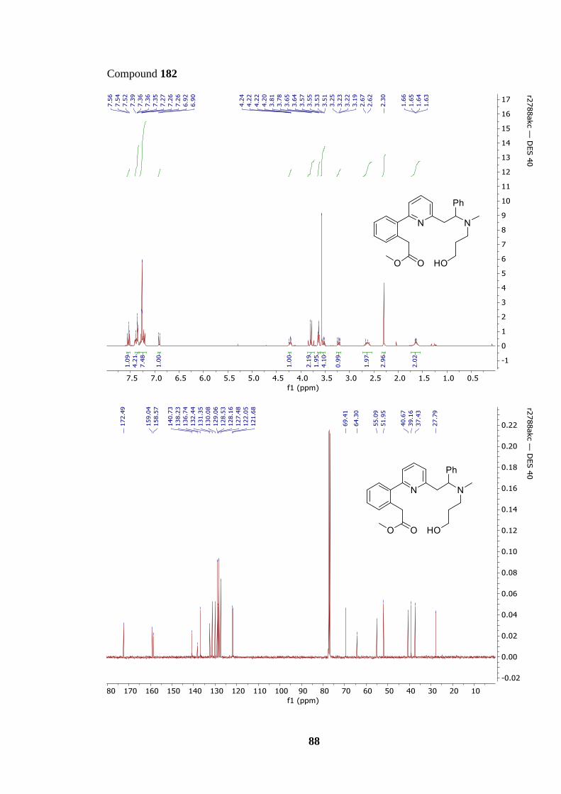
88
Compound 182

89
[2-(6-{2-[(3-Hydroxypropyl)(methyl)amino]-2-phenylethyl}pyridin-2-yl)phenyl]acetic
acid (162)
Methyl 2-[2-(6-{2-[(3-hydroxypropyl)(methyl)amino]-2-phenylethyl}pyridin-2-
yl)phenyl]acetate (182) (713 mg, 1.70 mmol) was dissolved in aqueous lithium hydroxide
solution (0.5 M, 17 mL, 8.52 mmol) and THF (17 mL). The resulting bi-phasic solution was
vigorously stirred for 18 h at 25 °C. Upon completion, the solvent was removed in vacuo.
Purification by flash column chromatography (SiO2, 50% methanol in ethyl acetate) afforded
the title compound as a brown powder (687 mg, 96%); m.p. 73–76 °C; Rf 0.20 (50%
methanol in ethyl acetate); νmax/cm–1 (neat) 3323, 3061, 3028, 2943, 2244, 1717, 1571, 1493,
1453, 1375, 1158, 1065; δH (400 MHz, CDCl3) 7.36 (1H, s, ArH), 7.47–7.45 (1H, d, J = 7.6
Hz, ArH), 7.38–7.17 (9H, m, ArH), 6.96 (1H, s, ArH), 4.07–4.03 (1H, t, J = 7.0 Hz,
NCHPh), 3.72–3.59 (2H, br, CH2CO2), 3.55–3.48 (3H, m, CH2OH and CHH′CHN), 3.20
(1H, br, CHH′CHN), 2.58 (2H, t, J = 7.0 Hz, NCH2), 2.28 (3H, s, NCH3), 1.75–1.53 (2H,
m, CH2); δC (100 MHz, CDCl3) 175.4 (CO2), 157.9 (ArC), 157.6 (ArC), 138.4 (ArC), 138.2
(ArC), 136.4 (ArCH), 134.1 (ArC), 131.3 (ArCH), 130.0 (ArCH), 129.1 (ArCH), 129.0
(ArCH), 128.3 (ArCH), 127.9 (ArCH), 127.1 (ArCH), 123.0 (ArCH), 122.6 (ArCH), 69.4
(NCHPh), 62.7 (CH2OH), 53.9 (NCH2), 42.1 (CH2CHN), 39.7 (CH2CO2), 37.3 (NCH3),
27.6 (CH2); HRMS (ESI): calcd. for C25H29N2O3, 405.2173. Found: [MH]+, 405.2176 (−0.8
ppm error)].
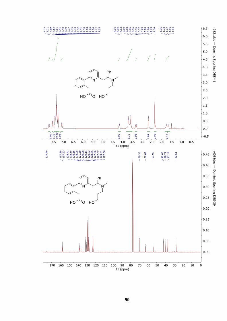
90
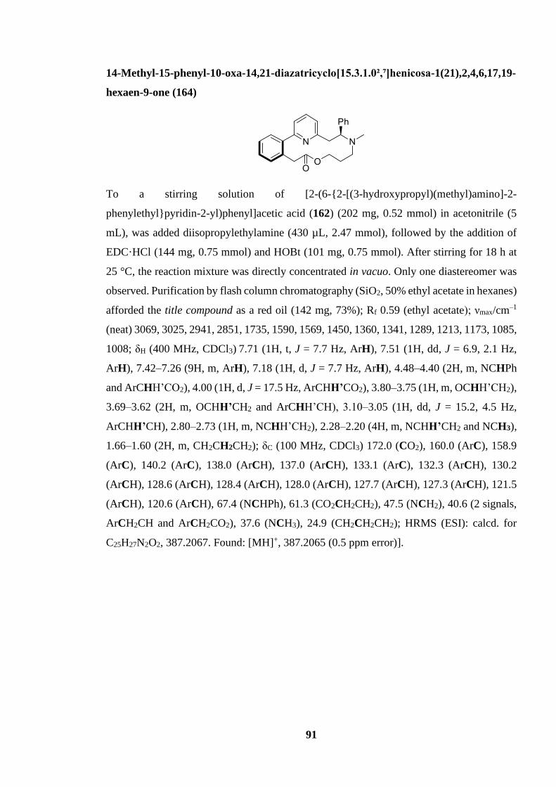
91
14-Methyl-15-phenyl-10-oxa-14,21-diazatricyclo[15.3.1.0²,⁷]henicosa-1(21),2,4,6,17,19-
hexaen-9-one (164)
To a stirring solution of [2-(6-{2-[(3-hydroxypropyl)(methyl)amino]-2-
phenylethyl}pyridin-2-yl)phenyl]acetic acid (162) (202 mg, 0.52 mmol) in acetonitrile (5
mL), was added diisopropylethylamine (430 µL, 2.47 mmol), followed by the addition of
EDC·HCl (144 mg, 0.75 mmol) and HOBt (101 mg, 0.75 mmol). After stirring for 18 h at
25 °C, the reaction mixture was directly concentrated in vacuo. Only one diastereomer was
observed. Purification by flash column chromatography (SiO2, 50% ethyl acetate in hexanes)
afforded the title compound as a red oil (142 mg, 73%); Rf 0.59 (ethyl acetate); νmax/cm–1
(neat) 3069, 3025, 2941, 2851, 1735, 1590, 1569, 1450, 1360, 1341, 1289, 1213, 1173, 1085,
1008; δH (400 MHz, CDCl3) 7.71 (1H, t, J = 7.7 Hz, ArH), 7.51 (1H, dd, J = 6.9, 2.1 Hz,
ArH), 7.42–7.26 (9H, m, ArH), 7.18 (1H, d, J = 7.7 Hz, ArH), 4.48–4.40 (2H, m, NCHPh
and ArCHH’CO2), 4.00 (1H, d, J = 17.5 Hz, ArCHH’CO2), 3.80–3.75 (1H, m, OCHH’CH2),
3.69–3.62 (2H, m, OCHH’CH2 and ArCHH’CH), 3.10–3.05 (1H, dd, J = 15.2, 4.5 Hz,
ArCHH’CH), 2.80–2.73 (1H, m, NCHH’CH2), 2.28–2.20 (4H, m, NCHH’CH2 and NCH3),
1.66–1.60 (2H, m, CH2CH2CH2); δC (100 MHz, CDCl3) 172.0 (CO2), 160.0 (ArC), 158.9
(ArC), 140.2 (ArC), 138.0 (ArCH), 137.0 (ArCH), 133.1 (ArC), 132.3 (ArCH), 130.2
(ArCH), 128.6 (ArCH), 128.4 (ArCH), 128.0 (ArCH), 127.7 (ArCH), 127.3 (ArCH), 121.5
(ArCH), 120.6 (ArCH), 67.4 (NCHPh), 61.3 (CO2CH2CH2), 47.5 (NCH2), 40.6 (2 signals,
ArCH2CH and ArCH2CO2), 37.6 (NCH3), 24.9 (CH2CH2CH2); HRMS (ESI): calcd. for
C25H27N2O2, 387.2067. Found: [MH]+, 387.2065 (0.5 ppm error)].

92
Compound 164

93
Methyl 4-[benzyl(3-hydroxypropyl)amino]butanoate (199)
Methyl 4-bromobutyrate (197) (0.69 mL, 5.54 mmol) and 3-(benzylamino)propan-1-ol (198)
(1.32 mL, 8.29 mmol) were dissolved in acetonitrile (55 mL) and potassium carbonate (1.53
g, 11.05 mmol) was added and the solution heated, at reflux, to 85 oC for 3 h. Upon
completion the solution was diluted with water (50 mL) before being extracted with ethyl
acetate (3 × 50 mL) and washed with sat. aq. brine (40 mL). The combined organic extracts
were dried over MgSO4, filtered and removed in vacuo. Purification by flash column
chromatography (SiO2, ethyl acetate) afforded the title compound as a colourless oil (572
mg, 39%); Rf 0.30 (ethyl acetate); νmax/cm-1 (neat) 3424, 2950, 2813, 1736; δH (400 MHz,
CDCl3) 7.33–7.26 (5H, m, Ph), 3.73 (2H, t, J = 3.7 Hz, CH2OH), 3.63 (1H, s, OCH3), 3.58
(2H, s, NCH2Ph), 2.67 (2H, t, J = 2.7 Hz, CH2CO2), 2.60 (2H, t, J = 2.5, NCH2CH2), 2.29
(2H, t, J = 2.3, NCH2CH2), 1.88–1.81 (2H, m, CH2CH2CH2), 1.76–1.68 (2H, m,
CH2CH2CH2); δC (100 MHz, CDCl3) 173.6 (CO2Me), 138.0 (C), 129.2 (CH), 128.6 (CH),
127.4 (CH), 64.2 (CH3O), 58.8 (CH2OH), 54.0 (CH2N), 52.9 (CH2N), 51.7 (CH2N), 31.8
(CH2CH2CO2), 28.1 (CH2CH2), 22.0 (CH2CH2); HRMS (ESI): calcd for C15H24NO3
266.1751. Found: [MNa]+, 266.1744 (2.6 ppm error).

94
Compound 199
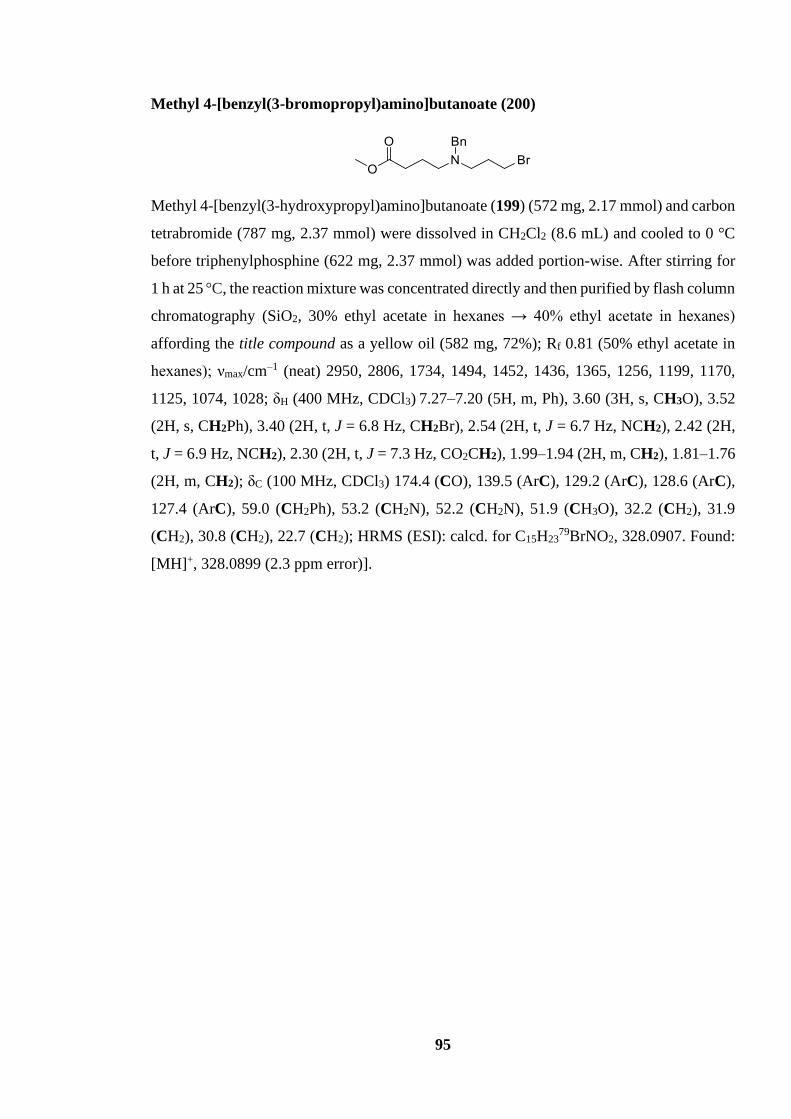
95
Methyl 4-[benzyl(3-bromopropyl)amino]butanoate (200)
Methyl 4-[benzyl(3-hydroxypropyl)amino]butanoate (199) (572 mg, 2.17 mmol) and carbon
tetrabromide (787 mg, 2.37 mmol) were dissolved in CH2Cl2 (8.6 mL) and cooled to 0 °C
before triphenylphosphine (622 mg, 2.37 mmol) was added portion-wise. After stirring for
1 h at 25 °C, the reaction mixture was concentrated directly and then purified by flash column
chromatography (SiO2, 30% ethyl acetate in hexanes → 40% ethyl acetate in hexanes)
affording the title compound as a yellow oil (582 mg, 72%); Rf 0.81 (50% ethyl acetate in
hexanes); νmax/cm–1 (neat) 2950, 2806, 1734, 1494, 1452, 1436, 1365, 1256, 1199, 1170,
1125, 1074, 1028; δH (400 MHz, CDCl3) 7.27–7.20 (5H, m, Ph), 3.60 (3H, s, CH3O), 3.52
(2H, s, CH2Ph), 3.40 (2H, t, J = 6.8 Hz, CH2Br), 2.54 (2H, t, J = 6.7 Hz, NCH2), 2.42 (2H,
t, J = 6.9 Hz, NCH2), 2.30 (2H, t, J = 7.3 Hz, CO2CH2), 1.99–1.94 (2H, m, CH2), 1.81–1.76
(2H, m, CH2); δC (100 MHz, CDCl3) 174.4 (CO), 139.5 (ArC), 129.2 (ArC), 128.6 (ArC),
127.4 (ArC), 59.0 (CH2Ph), 53.2 (CH2N), 52.2 (CH2N), 51.9 (CH3O), 32.2 (CH2), 31.9
(CH2), 30.8 (CH2), 22.7 (CH2); HRMS (ESI): calcd. for C15H2379BrNO2, 328.0907. Found:
[MH]+, 328.0899 (2.3 ppm error)].
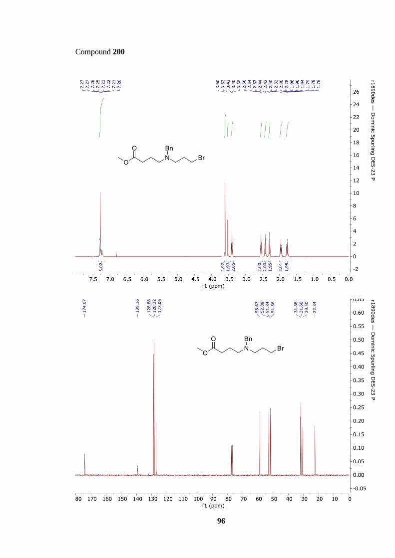
96
Compound 200

97
Methyl 4-[benzyl({3-[benzyl(3-hydroxypropyl)amino]propyl})amino]butanoate (201)
Methyl 4-[benzyl(3-bromopropyl)amino]butanoate (200) (1.21 g, 3.71 mmol), 3-
(benzylamino)propan-1-ol (198) (885 µL, 5.56 mmol) and potassium carbonate (1.03 g, 7.42
mmol) were dissolved in acetonitrile (37 mL). After stirring at 85 °C for 3 h the reaction
mixture was concentrated directly and then purified by flash column chromatography (SiO2,
5% methanol in ethyl acetae) affording the title compound as a yellow oil (710 mg, 45%);
Rf. 0.53 (10% methanol in ethyl acetate); νmax/cm–1 (neat) 3417, 3027, 2948, 2803, 1735,
1602, 1494, 1452, 1366, 1170, 1071, 1028; δH (400 MHz, CDCl3) 7.33–7.23 (10H, m, 2 ×
Ph), 3.73–3.70 (2H, m, CH2OH), 3.64 (3H, s, OCH3), 3.56 (2H, s, CH2Ph), 3.51 (2H, s,
CH2Ph), 2.65–2.62 (2H, t, J = 5.9 Hz, NCH2), 2.47–2.38 (6H, m, 3 × NCH2), 2.31–2.27 (2H,
t, J = 7.5 Hz, OCCH2), 1.75–1.65 (6H, m, 3 × CH2); δC (100 MHz, CDCl3) 174.2 (CO),
139.6 (ArC), 138.3 (ArC), 129.1 (ArC), 128.8 (ArC), 128.4 (ArC), 128.1 (ArC), 127.2
(ArC), 126.8 (ArC), 64.0 (CH2OH), 58.9 (CH2Ph), 58.6 (CH2Ph), 54.0 (CH2N), 52.8
(CH2N), 51.9 (CH2N), 51.7 (CH2N), 51.4 (COCH3), 31.7 (CH2), 28.0 (CH2), 24.3 (CH2),
22.4 (CH2); HRMS (ESI): calcd. for C25H37N2O3, 413.2799. Found: [MH]+, 413.2795 (1.0
ppm error)].
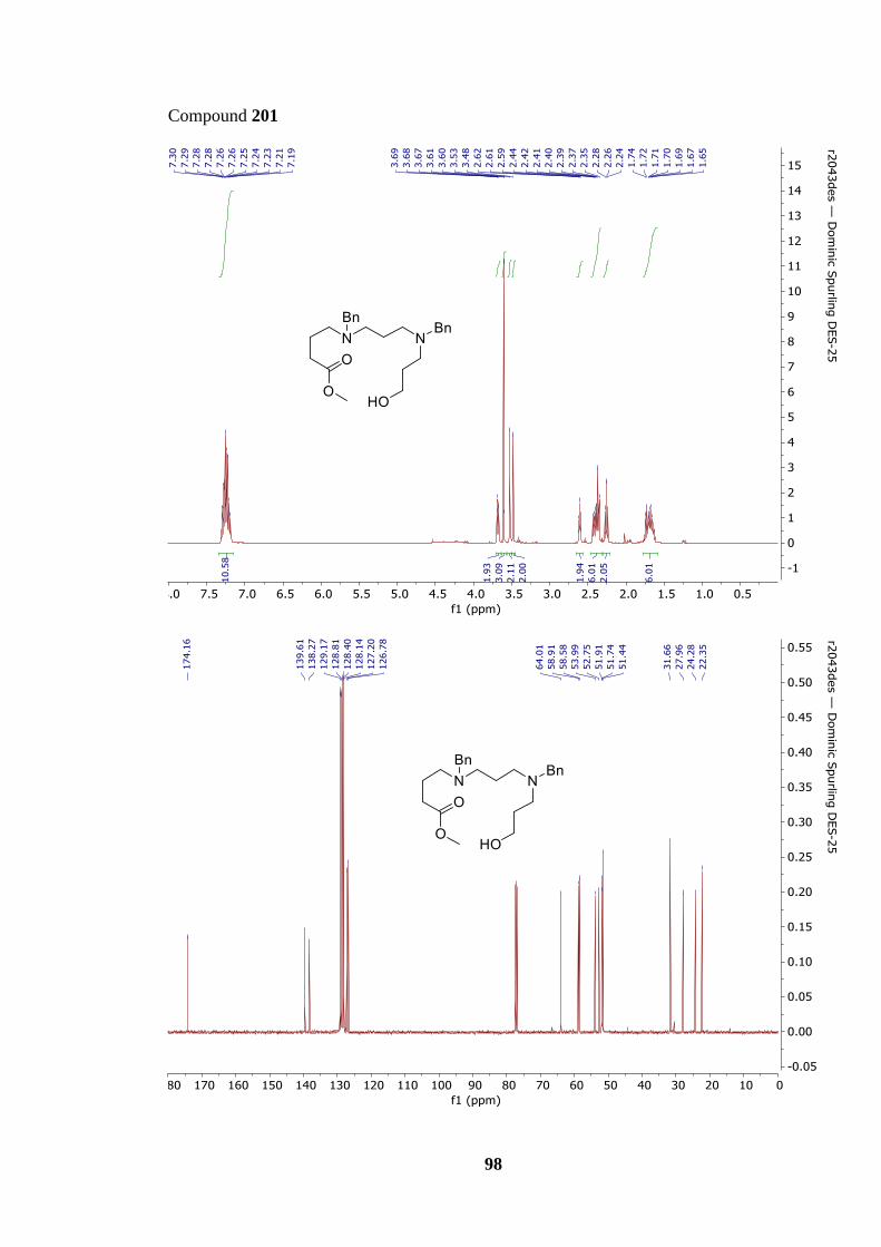
98
Compound 201
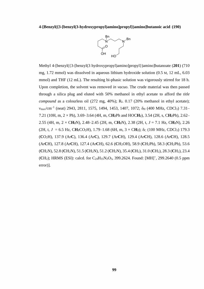
99
4-[Benzyl({3-[benzyl(3-hydroxypropyl)amino]propyl})amino]butanoic acid (190)
Methyl 4-[benzyl({3-[benzyl(3 hydroxypropyl)amino]propyl})amino]butanoate (201) (710
mg, 1.72 mmol) was dissolved in aqueous lithium hydroxide solution (0.5 M, 12 mL, 6.03
mmol) and THF (12 mL). The resulting bi-phasic solution was vigorously stirred for 18 h.
Upon completion, the solvent was removed in vacuo. The crude material was then passed
through a silica plug and eluted with 50% methanol in ethyl acetate to afford the title
compound as a colourless oil (272 mg, 40%); Rf. 0.17 (20% methanol in ethyl acetate);
νmax/cm–1 (neat) 2943, 2811, 1575, 1494, 1453, 1407, 1072; δH (400 MHz, CDCl3) 7.31–
7.21 (10H, m, 2 × Ph), 3.69–3.64 (4H, m, CH2Ph and HOCH2), 3.54 (2H, s, CH2Ph), 2.62–
2.55 (4H, m, 2 × CH2N), 2.48–2.45 (2H, m, CH2N), 2.38 (2H, t, J = 7.1 Hz, CH2N), 2.26
(2H, t, J = 6.5 Hz, CH2CO2H), 1.79–1.68 (6H, m, 3 × CH2); δC (100 MHz, CDCl3) 179.3
(CO2H), 137.9 (ArC), 136.4 (ArC), 129.7 (ArCH), 129.4 (ArCH), 128.6 (ArCH), 128.5
(ArCH), 127.8 (ArCH), 127.4 (ArCH), 62.6 (CH2OH), 58.9 (CH2Ph), 58.3 (CH2Ph), 53.6
(CH2N), 52.8 (CH2N), 51.5 (CH2N), 51.2 (CH2N), 35.4 (CH2), 31.0 (CH2), 28.3 (CH2), 23.4
(CH2); HRMS (ESI): calcd. for C24H35N2O3, 399.2624. Found: [MH]+, 299.2640 (0.5 ppm
error)].
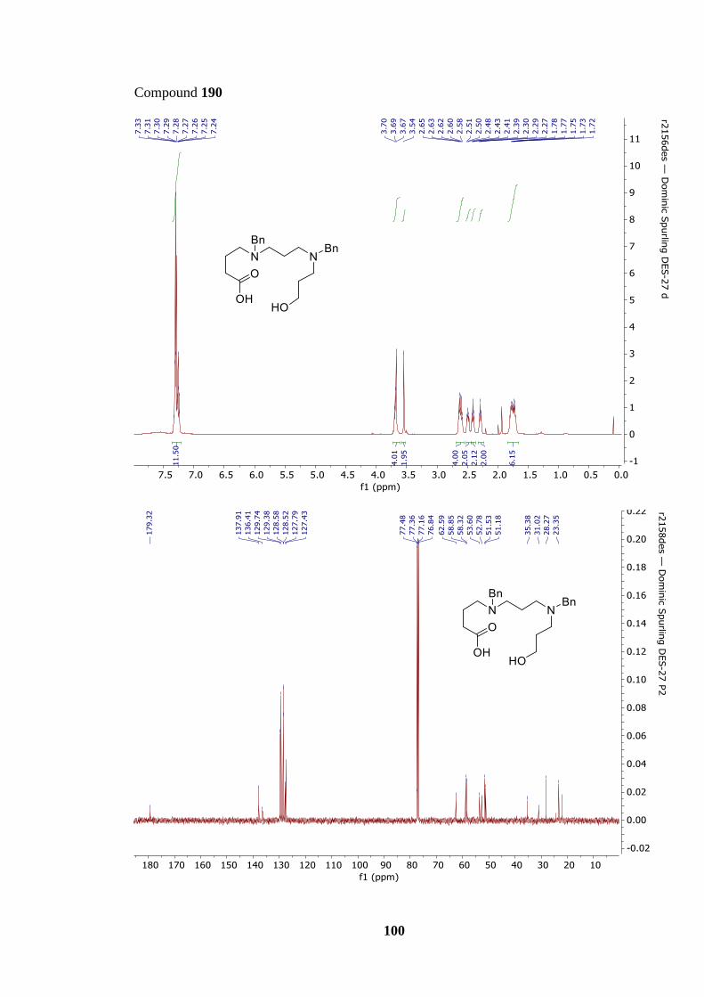
100
Compound 190

101
5,9-Dibenzyl-1-oxa-5,9-diazacyclotridecan-13-one (192)
To a stirring solution of 4-[benzyl({3-[benzyl(3-
hydroxypropyl)amino]propyl})amino]butanoic acid (190) (186 mg, 0.47 mmol) in
acetonitrile (5 mL), was added diisopropylethylamine (435 μL, 2.50 mmol), followed by the
addition of EDC·HCl (144 mg, 0.75 mmol) and HOBt (101 mg, 0.75 mmol). After stirring
for 18 h at 25 °C, the reaction mixture was concentrated directly and then purified by flash
column chromatography (SiO2, 50% ethyl acetate in hexanes) to afford the title compound
as a colourless oil (87 mg, 49%); Rf. 0.40 (50% ethyl acetate in hexanes); νmax/cm–1 (neat)
3027, 2928, 2796, 1728, 1602, 1494, 1452, 1372, 1356, 1340, 1231, 1208, 1171, 1119, 1070,
1028; δH (400 MHz, CDCl3) 7.29–7.20 (10H, m, 2 × Ph), 4.23–4.20 (2H, m, OCH2), 3.49
(2H, s, CH2Ph), 3.47 (2H, s, CH2Ph), 2.65–2.62 (2H, t, J = 6.3 Hz, NCH2), 2.51–2.44 (4H,
m, 2 × NCH2), 2.35–2.31 (4H, m, NCH2 and CH2CO2), 1.19–1.68 (4H, m, 2 × CH2), 1.59–
1.53 (2H, m, CH2); δC (100 MHz, CDCl3) 174.3 (CO2), 140.1 (ArC), 139.8 (ArC), 129.2
(ArCH), 129.0 (ArCH), 128.3 (ArCH), 128.2 (ArCH), 127.0 (ArCH), 126.9 (ArCH), 62.1
(CH2O), 59.4 (CH2Ph), 59.2 (CH2Ph), 52.7 (CH2N), 52.6 (CH2N), 52.2 (CH2N), 49.7
(CH2N), 31.9 (CH2CO2), 26.6 (CH2), 26.4 (CH2), 23.3 (CH2); HRMS (ESI): calcd. for
C24H33N2O2, 381.2537. Found: [MH]+, 381.2530 (1.7 ppm error)].

102
Compound 192

103
5,9-Dibenzyl-1-oxa-5,9-diazacyclotetradecan-14-one (203)
To a stirring solution of 5-(benzyl(3-(benzyl(3-
hydroxypropyl)amino)propyl)amino)pentanoic acid (202) (261 mg, 0.633 mmol) in
acetonitrile (6 mL), was added diisopropylethylamine (550 μL, 3.17 mmol), followed by the
addition of EDC·HCl (182 mg, 0.95 mmol) and HOBt (128 mg, 0.95 mmol). After stirring
for 18 h at 25 °C, the reaction mixture was concentrated directly and then purified by flash
column chromatography (SiO2, 50% ethyl acetate in hexanes) to afford the title compound
as a colourless oil (52 mg, 20%); Rf 0.45 (ethyl acetate); νmax/cm–1 (neat) 2930, 2795, 1730,
1699, 1494, 1452, 1238, 1238, 1155, 1070, 1028; δH (400 MHz, CDCl3) 7.23–7.20 (10H, m,
2 × Ph), 4.24 (2H, t, J = 5.3 Hz, OCH2), 3.51 (2H, s, CH2Ph), 3.48 (2H, s, CH2Ph), 2.63
(2H, t, J = 6.8 Hz, NCH2), 2.47–2.34 (8H, m, 3 × NCH2 and CH2CO2), 1.90–1.84 (2H, m,
CH2), 1.73–1.60 (2H, m, CH2), 1.56–1.48 (2H, m, CH2); δC (100 MHz, CDCl3) 174.1 (CO2),
139.8 (2 × ArC), 128.8 (ArCH), 128.8 (ArCH), 128.3 (ArCH), 128.2 (ArCH), 126.9
(ArCH), 126.8 (ArCH), 61.4 (CH2O), 60.0 (CH2Ph), 58.7 (CH2Ph), 52.4 (CH2N), 52.2
(CH2N), 49.8 (CH2N), 48.5 (CH2N), 34.7 (CH2CO2), 26.66 (CH2), 25.5 (CH2), 24.5 (CH2),
23.1 (CH2); HRMS (ESI): calcd. for C25H35N2O2, 395.2687 Found: [MH]+, 395.2693 (1.6
ppm error)].

104
Compound 203

105
N-(3-bromopropyl)aniline (213)
1,3-Dibromopropane (216) (19.6 mL, 0.19 mol) and aniline (2.94 mL, 32.2 mmol) were
dissolved in acetonitrile (65 mL). After stirring at 85 °C for 3 h the reaction mixture was
diluted with water (50 mL), extracted with ethyl acetate (3 × 30 mL) and washed with sat.
brine (30 mL). The combined organic extracts were dried over MgSO4, filtered, and then
purified by flash column chromatography (SiO2, 5% diethyl ether in hexanes) affording the
title compound as an orange oil (2.23 g, 33%); Rf. 0.39 (10% ethyl acetate in hexanes); δH
(400 MHz, CDCl3) 7.23–7.19 (2H, m, 2 × PhH), 6.80–6.71 (3H, m, 3 × PhH), 3.51 (2H, t, J
= 6.5 Hz, BrCH2), 3.35 (2H, t, J = 6.6 Hz, CH2N), 2.22–2.15 (2H, m, CH2CH2CH2).
Spectroscopic data matched those reported in the literature.67
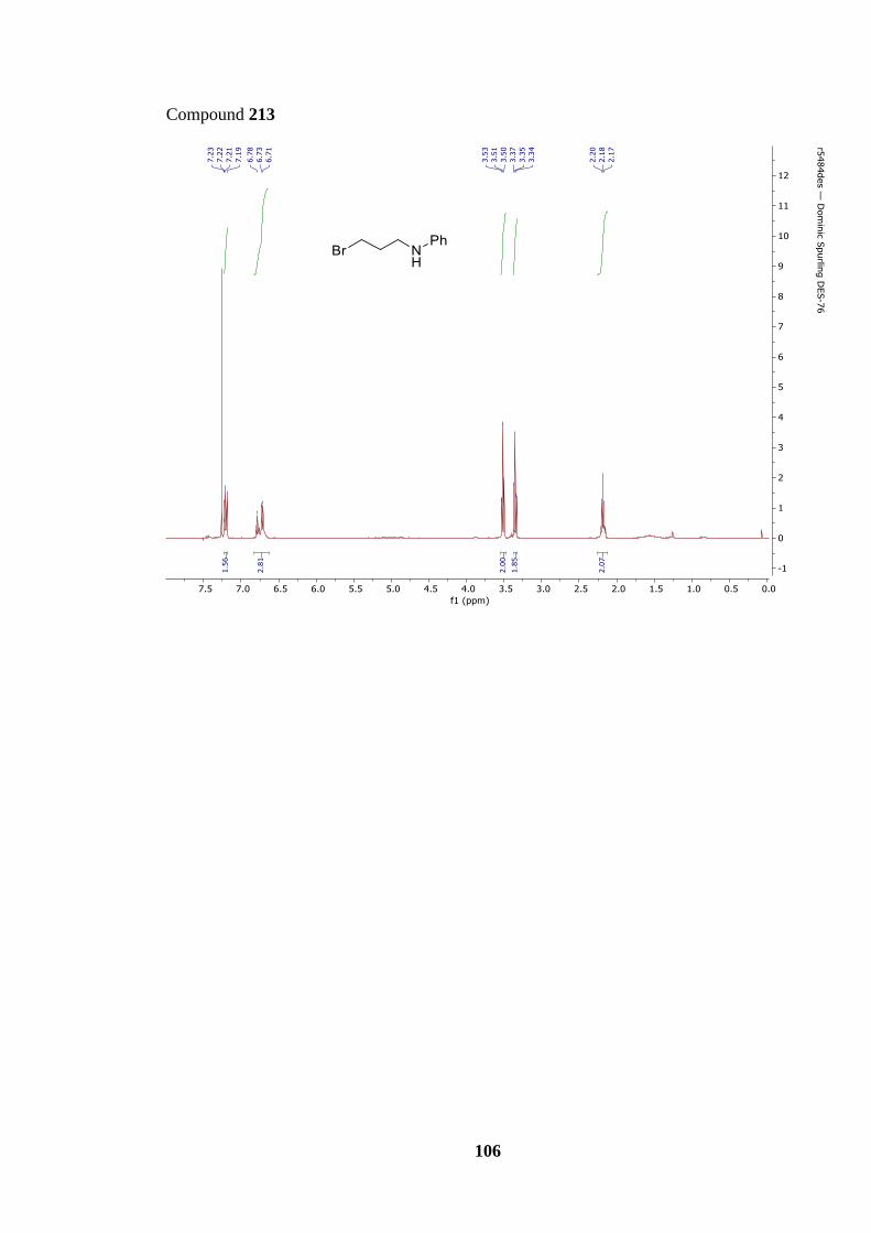
106
Compound 213

107
N1-(2-(6-Bromopyridin-2-yl)-1-phenylethyl)-N1-methyl-N3-phenylpropane-1,3-
diamine (214)
[2-(6-Bromopyridin-2-yl)-1-phenylethyl](methyl)amine (174) (1.53 g, 5.31 mmol), N-(3-
bromopropyl)aniline (213) (1.69 g, 7.96 mmol) and potassium carbonate (1.46 g, 10.6 mmol)
was dissolved in acetonitrile (50 mL). After stirring at 85 °C for 18 h the reaction mixture
was quenched with water and extracted with ethyl acetate (3 × 30 mL). The combined
organic layers were dried with anhydrous MgSO4, filtered, and concentrated in vacuo.
Purification via flash column chromatography (SiO2, 50% diethyl ether in hexane) afforded
the title compound as a yellow oil (667 mg, 30%); Rf 0.61 (ethyl acetate); νmax/cm–1 (neat)
3030, 2941, 2856, 2796, 1602, 1583, 1563, 1505, 1434, 1405, 1319, 1259, 1178, 1115; δH
(400 MHz, CDCl3) 7.34–7.17 (9H, m, ArH), 6.93 (1H, d, J = 7.4 Hz, ArH), 6.71 (1H, t, J =
7.3 Hz, ArH), 6.54 (2H, d, J = 7.8 Hz, ArH), 4.18 (1H, t, J = 7.0 Hz, NCHPh), 3.54–3.48
(1H, dd, J = 13.7, 7.0 Hz, ArCHH’CH), 3.16–3.10 (1H, dd, J = 13.7, 7.0 Hz, CCHH’CH),
3.08–3.03 (2H, m, CH2NHPh), 2.60–2.53 (1H, dt, J = 12.8, 6.2 Hz, CH3NCHH’CH2), 2.47–
2.41 (1H, dt, J = 12.8, 6.2 Hz, CH3NCHH’CH2), 2.26 (3H, s, CH3N), 1.78–1.67 (2H, m,
CH2CH2CH2); δC (100 MHz, CDCl3) 161.6 (ArC), 148.6 (ArC), 141.3 (ArC), 138.8 (ArC),
138.3 (ArC), 129.7 (ArC), 128.8 (ArC), 128.0 (ArC), 127.3 (ArC), 125.4 (ArC), 122.7
(ArC), 116.8 (ArC), 112.8 (ArC), 68.3 (PhCHN), 52.2 (CH3NCH2), 42.1 (CH2CH2NHPh),
40.3 (CCH2CHN), 37.7 (CH3N), 26.2 (CH2CH2CH2); HRMS (ESI): calcd. for
C23H2779BrN3, 424.1383. Found: [MH]+, 424.1388 (−1.1 ppm error)].

108
Compound 214

109
Methyl 2-(2-(6-(2-(methyl(3-(phenylamino)propyl)amino)-2-phenylethyl)pyridin-2-
yl)phenyl)acetate (218)
N1-(2-(6-bromopyridin-2-yl)-1-phenylethyl)-N1-methyl-N3-phenylpropane-1,3-diamine
(214) (667 mg, 1.85 mmol), methyl 2-(2-(4,4,5,5-tetramethyl-1,3,2-dioxaborolan-2-
yl)phenyl) acetate (181) (765 mg, 2.77 mmol), potassium phosphate (784 mg, 3.69 mmol)
and PdCl2(dppf).CH2Cl2 (75.0 mg, 0.092 mmol) were charged into an RBF purged with
nitrogen. THF (18 mL) and de-ionised water (140 µL, 4.37 mmol) were added and heated to
80 °C, at reflux, for 18 h. Upon completion the solution was cooled to room temperature,
diluted with water (20 mL), extracted with ethyl acetate (3 × 30 mL) and washed with brine
(15 mL). The combined organic extracts were dried over MgSO4, filtered, and removed in
vacuo. Purification by flash column chromatography (SiO2, 5% methanol in diethyl ether)
afforded the title compound as a yellow oil (715 mg, 76%); Rf 0.70 (10% methanol in ethyl
acetate); νmax/cm–1 (neat) 3403, 3025, 2948, 2848, 2803, 1733, 1602, 1569, 1506, 1447,
1320, 1254, 1211, 1157, 1083, 1044, 1004; δH (400 MHz, CDCl3) 7.49 (1H, t, J = 7.7 Hz,
ArH), 7.40–7.18 (10H, m, ArH), 6.92 (1H, d, J = 7.7 Hz, ArH), 6.64–6.66 (1H, m, ArH),
6.46 (2H, d, J = 7.9, ArH), 4.19 (1H, dd, J = 8.3, 6.7 Hz, NCHPh), 3.80 (2H, d, J = 9.9 Hz,
CH2CO2Me), 3.55–3.50 (4H, m, CO2CH3 and CCHH’CHPh), 3.23–3.18 (1H, dd, J = 13.4,
8.3 Hz, CCHH’CHPh), 3.06–2.99 (2H, m, CH2CH2CNHPh), 2.58–2.51 (1H, dt, J = 13.4,
6.7 Hz, MeNCHH’CH2), 2.48–2.41 (1H, dt, J = 12.9, 6.7 Hz, MeNCHH’CH2), 2.27 (3H, s,
CH3N), 1.75–1.64 (2H, m, CH2CH2CH2); δC (100 MHz, CDCl3) 172.4 (CO2Me), 159.1
(ArC), 158.8 (ArC), 148.6 (ArC), 140.6 (ArC), 139.3 (ArC), 136.5 (ArCH), 132.4 (ArC),
131.4 (ArCH), 130.0 (ArCH), 129.1 (ArCH), 128.9 (ArCH), 128.4 (ArCH), 128.0 (ArCH),
127.4 (ArCH), 127.1 (ArCH), 122.0 (ArCH), 121.3 (ArCH), 116.8 (ArCH), 112.7 (ArCH),
68.5 (NCHPh), 52.4 (MeNCH2CH2), 51.8 (CO2CH3), 42.2 (CH2CH2NHPh), 40.5
(CCH2CHPh), 39.1 (CCH2CO2), 37.7 (CH3N), 26.3 (CH2CH2CH2); HRMS (ESI): calcd.
For C32H36N3O2, 494.2802. Found: [MH]+, 494.2809 (−1.4 ppm error)].

110
Compound 218
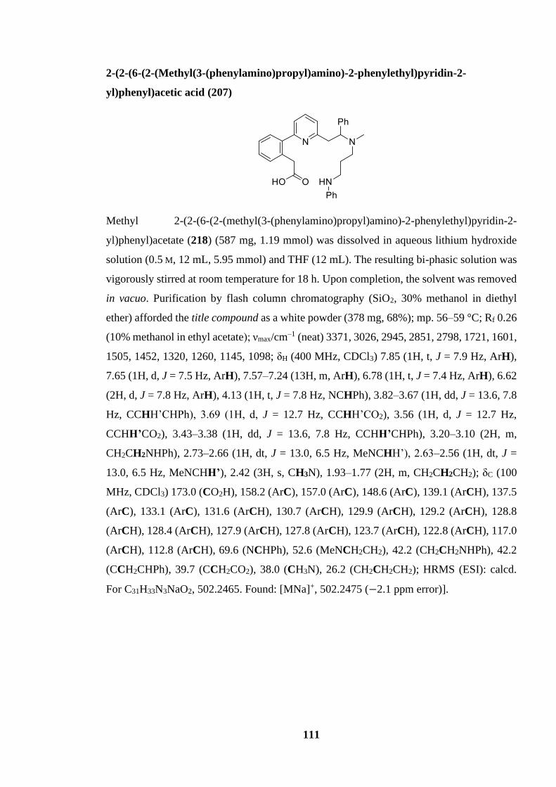
111
2-(2-(6-(2-(Methyl(3-(phenylamino)propyl)amino)-2-phenylethyl)pyridin-2-
yl)phenyl)acetic acid (207)
Methyl 2-(2-(6-(2-(methyl(3-(phenylamino)propyl)amino)-2-phenylethyl)pyridin-2-
yl)phenyl)acetate (218) (587 mg, 1.19 mmol) was dissolved in aqueous lithium hydroxide
solution (0.5 M, 12 mL, 5.95 mmol) and THF (12 mL). The resulting bi-phasic solution was
vigorously stirred at room temperature for 18 h. Upon completion, the solvent was removed
in vacuo. Purification by flash column chromatography (SiO2, 30% methanol in diethyl
ether) afforded the title compound as a white powder (378 mg, 68%); mp. 56–59 °C; Rf 0.26
(10% methanol in ethyl acetate); νmax/cm–1 (neat) 3371, 3026, 2945, 2851, 2798, 1721, 1601,
1505, 1452, 1320, 1260, 1145, 1098; δH (400 MHz, CDCl3) 7.85 (1H, t, J = 7.9 Hz, ArH),
7.65 (1H, d, J = 7.5 Hz, ArH), 7.57–7.24 (13H, m, ArH), 6.78 (1H, t, J = 7.4 Hz, ArH), 6.62
(2H, d, J = 7.8 Hz, ArH), 4.13 (1H, t, J = 7.8 Hz, NCHPh), 3.82–3.67 (1H, dd, J = 13.6, 7.8
Hz, CCHH’CHPh), 3.69 (1H, d, J = 12.7 Hz, CCHH’CO2), 3.56 (1H, d, J = 12.7 Hz,
CCHH’CO2), 3.43–3.38 (1H, dd, J = 13.6, 7.8 Hz, CCHH’CHPh), 3.20–3.10 (2H, m,
CH2CH2NHPh), 2.73–2.66 (1H, dt, J = 13.0, 6.5 Hz, MeNCHH’), 2.63–2.56 (1H, dt, J =
13.0, 6.5 Hz, MeNCHH’), 2.42 (3H, s, CH3N), 1.93–1.77 (2H, m, CH2CH2CH2); δC (100
MHz, CDCl3) 173.0 (CO2H), 158.2 (ArC), 157.0 (ArC), 148.6 (ArC), 139.1 (ArCH), 137.5
(ArC), 133.1 (ArC), 131.6 (ArCH), 130.7 (ArCH), 129.9 (ArCH), 129.2 (ArCH), 128.8
(ArCH), 128.4 (ArCH), 127.9 (ArCH), 127.8 (ArCH), 123.7 (ArCH), 122.8 (ArCH), 117.0
(ArCH), 112.8 (ArCH), 69.6 (NCHPh), 52.6 (MeNCH2CH2), 42.2 (CH2CH2NHPh), 42.2
(CCH2CHPh), 39.7 (CCH2CO2), 38.0 (CH3N), 26.2 (CH2CH2CH2); HRMS (ESI): calcd.
For C31H33N3NaO2, 502.2465. Found: [MNa]+, 502.2475 (−2.1 ppm error)].

112
Compound 207
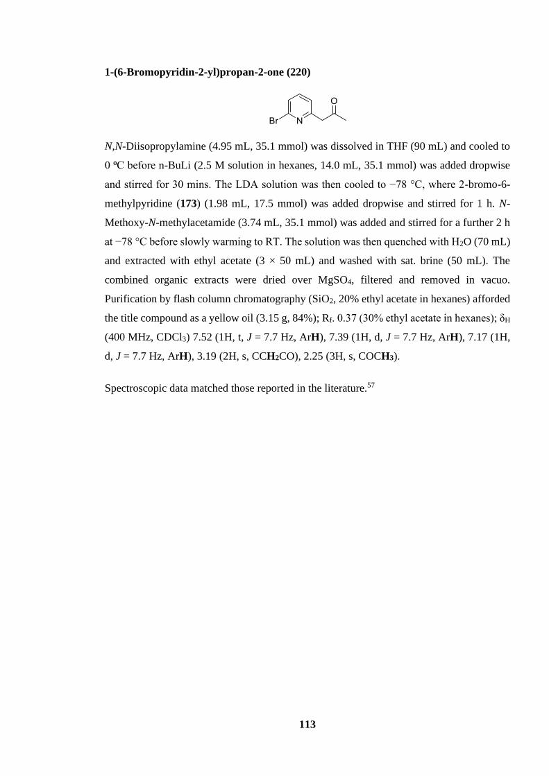
113
1-(6-Bromopyridin-2-yl)propan-2-one (220)
N,N-Diisopropylamine (4.95 mL, 35.1 mmol) was dissolved in THF (90 mL) and cooled to
0 ⁰C before n-BuLi (2.5 M solution in hexanes, 14.0 mL, 35.1 mmol) was added dropwise
and stirred for 30 mins. The LDA solution was then cooled to −78 °C, where 2-bromo-6-
methylpyridine (173) (1.98 mL, 17.5 mmol) was added dropwise and stirred for 1 h. N-
Methoxy-N-methylacetamide (3.74 mL, 35.1 mmol) was added and stirred for a further 2 h
at −78 °C before slowly warming to RT. The solution was then quenched with H2O (70 mL)
and extracted with ethyl acetate (3 × 50 mL) and washed with sat. brine (50 mL). The
combined organic extracts were dried over MgSO4, filtered and removed in vacuo.
Purification by flash column chromatography (SiO2, 20% ethyl acetate in hexanes) afforded
the title compound as a yellow oil (3.15 g, 84%); Rf. 0.37 (30% ethyl acetate in hexanes); δH
(400 MHz, CDCl3) 7.52 (1H, t, J = 7.7 Hz, ArH), 7.39 (1H, d, J = 7.7 Hz, ArH), 7.17 (1H,
d, J = 7.7 Hz, ArH), 3.19 (2H, s, CCH2CO), 2.25 (3H, s, COCH3).
Spectroscopic data matched those reported in the literature.57

114
Compound 220

115
N-(1-(6-Bromopyridin-2-yl)propan-2-yl)aniline (221)
To a solution of 1-(6-bromopyridin-2-yl)propan-2-one (220) (3.15 g, 14.8 mmol) in
dichloroethane (73 mL) at room temperature, aniline (1.62 mL, 17.7 mmol), acetic acid (1.02
mL, 17.7 mmol) and sodium triacetoxyborohydride (4.70 g, 22.2 mmol) were added
sequentially. The reaction mixture was stirred at room temperature overnight. The solution
was then quenched with 70 mL of 1 M NaOH and extracted with ethyl acetate (3× 50 mL)
and washed with sat. brine (50 mL). The combined organic layers were dried over anhydrous
MgSO4, filtered and concentrated in vacuo. Purification via flash column chromatography
(SiO2, 20% ethyl acetate in hexanes) afforded the title compound as a yellow oil (3.76 g,
88%); Rf. 0.41 (20% ethyl acetate in hexanes); δH (400 MHz, CDCl3) 7.43 (1H, t, J = 7.7
Hz, ArH), 7.32 (1H, d, J = 7.7 Hz, ArH), 7.18–7.10 (3H, m, ArH), 6.69 (1H, t, J = 7.32 Hz,
ArH), 6.62 (2H, d, J = 7.3 Hz, ArH), 3.97–3.89 (1H, m, CH2CHN), 3.01 (1H, dd, J = 13.7,
6.7 Hz, CHH’CHN), 2.90 (1H, dd, J = 13.7, 6.7 Hz, CHH’CHN), 1.22 (3H, d, J = 6.2 Hz,
CH3).
Spectroscopic data matched those reported in the literature. 57

116
Compound 221

117
N-(3-((tert-Butyldimethylsilyl)oxy)propyl)aniline (226)
To a solution of 3-(phenylamino)propan-1-ol (223) (1.81 mL, 13.2 mmol) in
dichloromethane (130 mL) at room temperature, tert-butylchlorodimethylsilane (3.99 g,
26.5 mmol), imidazole (1.35 g, 19.9 mmol) and 4-dimethylaminopyridine (162 mg, 1.33
mmol) were added. The reaction mixture was stirred at room temperature for 2 hours. The
solution was then worked up with 100 mL of water and extracted with ethyl acetate (3× 50
mL) and washed with sat. brine (50 mL). The combined organic layers were dried over
anhydrous MgSO4, filtered and concentrated in vacuo. Purification via flash column
chromatography (SiO2, 5% ethyl acetate in hexanes) afforded the title compound as a yellow
oil (2.06 g, 59%) Rf. 0.45 (5% ethyl acetate in hexanes); δH (400 MHz, CDCl3) 7.18 (2H, t,
J = 7.8 Hz, Ph), 6.72–6.70 (1H, m, Ph), 6.63 (2H, d, J = 7.8 Hz, Ph), 3.77 (2H, t, J = 5.8 Hz,
PhNCH2), 3.24 (2H, t, J = 6.4, CH2OTBS), 1.88–1.82 (2H, m, CH2CH2CH2), 0.92 (9H, s, 3
× SiCCH3), 0.07 (6H, s, 2 × SiCH3).
Spectroscopic data matched those reported in the literature.68

118
Compound 226
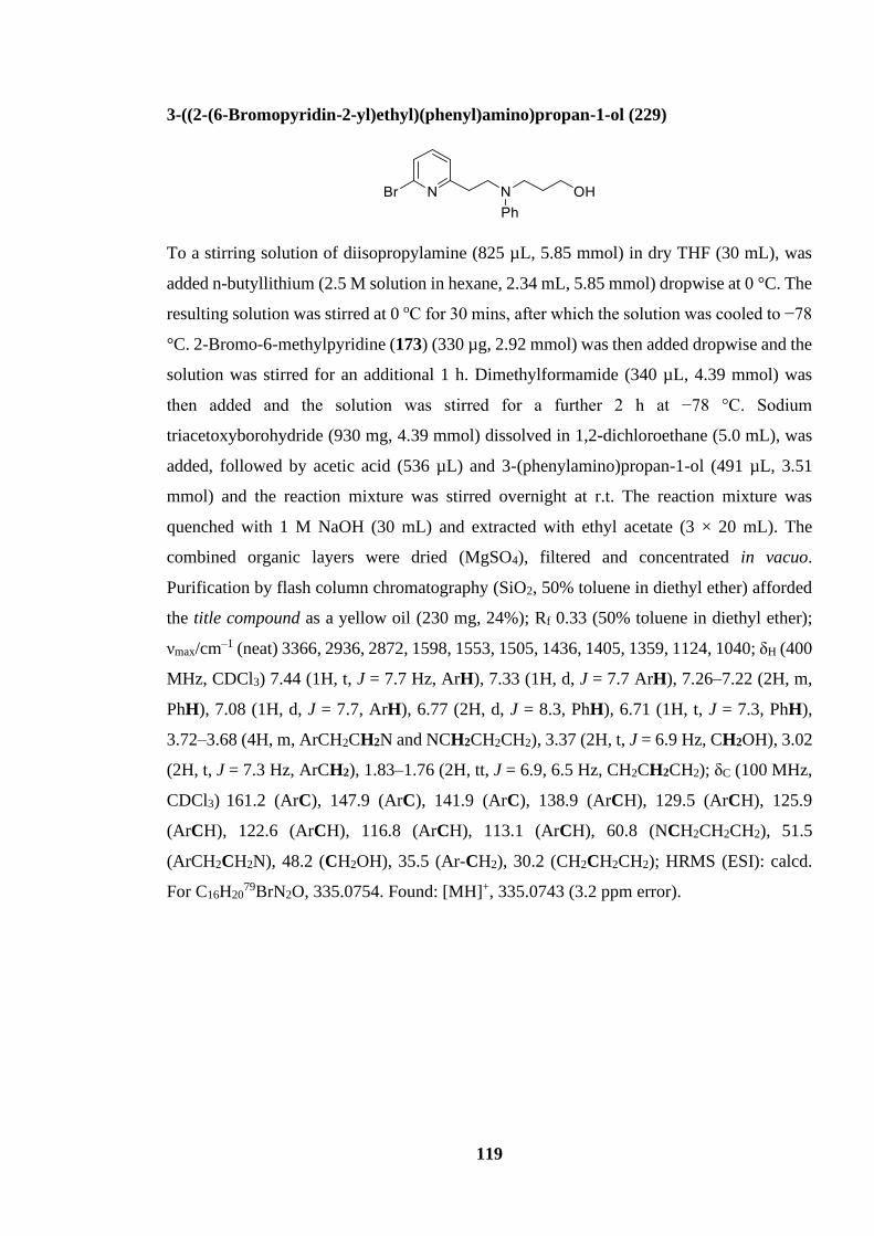
119
3-((2-(6-Bromopyridin-2-yl)ethyl)(phenyl)amino)propan-1-ol (229)
To a stirring solution of diisopropylamine (825 µL, 5.85 mmol) in dry THF (30 mL), was
added n-butyllithium (2.5 M solution in hexane, 2.34 mL, 5.85 mmol) dropwise at 0 °C. The
resulting solution was stirred at 0 oC for 30 mins, after which the solution was cooled to −78
°C. 2-Bromo-6-methylpyridine (173) (330 µg, 2.92 mmol) was then added dropwise and the
solution was stirred for an additional 1 h. Dimethylformamide (340 µL, 4.39 mmol) was
then added and the solution was stirred for a further 2 h at −78 °C. Sodium
triacetoxyborohydride (930 mg, 4.39 mmol) dissolved in 1,2-dichloroethane (5.0 mL), was
added, followed by acetic acid (536 µL) and 3-(phenylamino)propan-1-ol (491 µL, 3.51
mmol) and the reaction mixture was stirred overnight at r.t. The reaction mixture was
quenched with 1 M NaOH (30 mL) and extracted with ethyl acetate (3 × 20 mL). The
combined organic layers were dried (MgSO4), filtered and concentrated in vacuo.
Purification by flash column chromatography (SiO2, 50% toluene in diethyl ether) afforded
the title compound as a yellow oil (230 mg, 24%); Rf 0.33 (50% toluene in diethyl ether);
νmax/cm–1 (neat) 3366, 2936, 2872, 1598, 1553, 1505, 1436, 1405, 1359, 1124, 1040; δH (400
MHz, CDCl3) 7.44 (1H, t, J = 7.7 Hz, ArH), 7.33 (1H, d, J = 7.7 ArH), 7.26–7.22 (2H, m,
PhH), 7.08 (1H, d, J = 7.7, ArH), 6.77 (2H, d, J = 8.3, PhH), 6.71 (1H, t, J = 7.3, PhH),
3.72–3.68 (4H, m, ArCH2CH2N and NCH2CH2CH2), 3.37 (2H, t, J = 6.9 Hz, CH2OH), 3.02
(2H, t, J = 7.3 Hz, ArCH2), 1.83–1.76 (2H, tt, J = 6.9, 6.5 Hz, CH2CH2CH2); δC (100 MHz,
CDCl3) 161.2 (ArC), 147.9 (ArC), 141.9 (ArC), 138.9 (ArCH), 129.5 (ArCH), 125.9
(ArCH), 122.6 (ArCH), 116.8 (ArCH), 113.1 (ArCH), 60.8 (NCH2CH2CH2), 51.5
(ArCH2CH2N), 48.2 (CH2OH), 35.5 (Ar-CH2), 30.2 (CH2CH2CH2); HRMS (ESI): calcd.
For C16H2079BrN2O, 335.0754. Found: [MH]+, 335.0743 (3.2 ppm error).
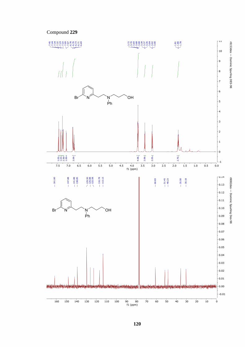
120
Compound 229

121
Methyl 4-iodobutanoate (238)
Methyl 4-bromobutanoate (197) (630 µL, 5.00 mmol) and sodium iodide (2.98 g, 20.0
mmol) was dissolved in acetonitrile (12 mL). After stirring at 70 °C for 90 min the reaction
mixture was quenched with sat. aq. sodium thiosulfate (20 mL), extracted with ethyl acetate
(3 × 20 mL) and washed with sat. brine (10 mL). The combined organic extracts were dried
over MgSO4, filtered and concentrated in vacuo to afford the title compound as a yellow oil
(1.14 g, 100%); Rf. 0.8 (50% ethyl acetate in hexanes); δH (400 MHz, CDCl3) 3.69 (3H, s,
CH3CO2), 3.24 (2H, t, J = 6.0 Hz, ICH2), 2.46 (2H, t, J = 7.0 Hz, CO2CH2), 2.16–2.11 (2H,
tt, J = 7.0, 6.0 Hz, CH2CH2CH2).
Spectroscopic data matched those reported in the literature.69
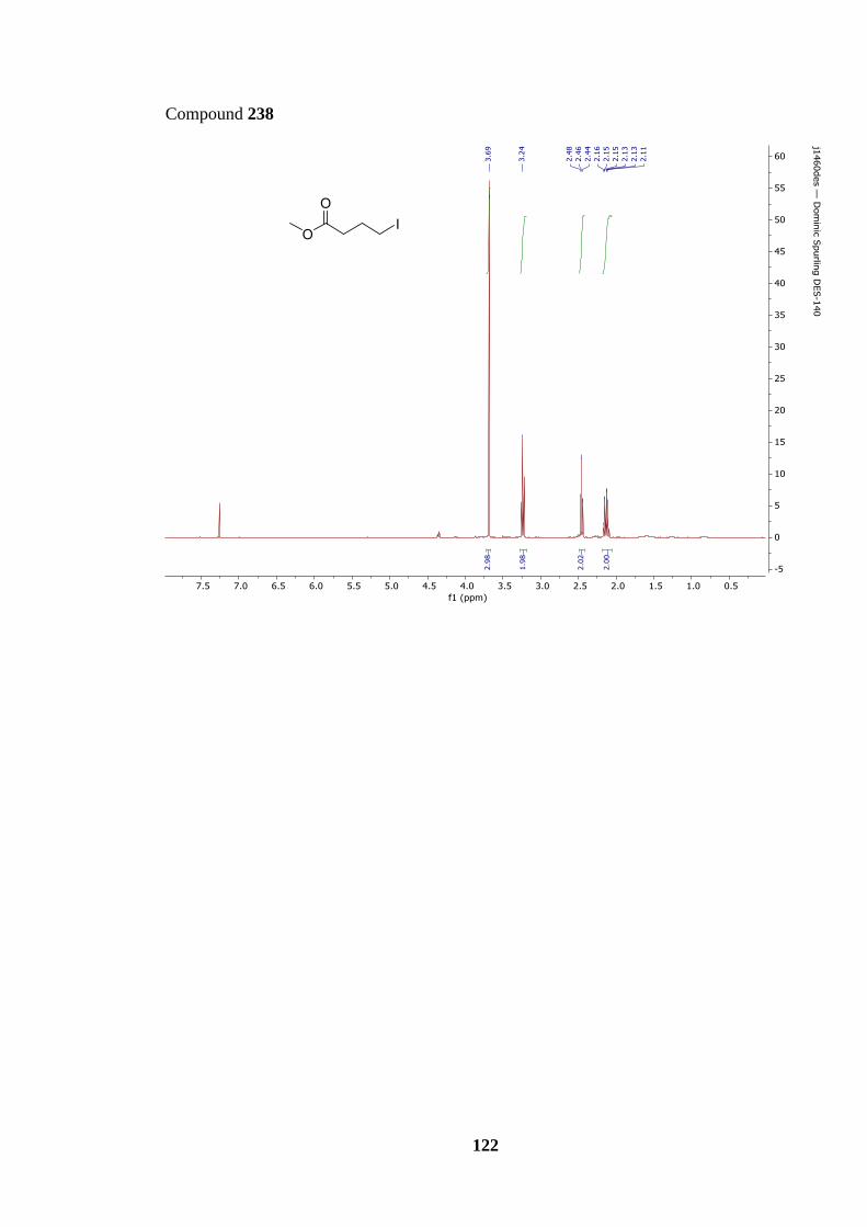
122
Compound 238

123
(4-Methoxy-4-oxobutyl)zinc(II) bromide (239)
To a round bottom flask purged with nitrogen 1,2-dibromoethane (43 µL, 0.50 mmol) was
dissolved in dry DMF (8 mL) before zinc powder (654 mg, 10.0 mmol) was added and the
solution was heated at 90 ⁰C and stirred for 30 mins. The solution was then cooled to r.t.,
where chlorotriethylsilane (23.0 µL, 0.13 mmol) was added and stirred for 15 min. Methyl
4-iodobutanoate (238) (1.14 g, 5.00 mmol) dissolved in THF (4 mL) was then added and
stirred for a further 2.5 h at 40 °C before cooling to room temperature. The resulting grey
precipitate in the solution was then left to settle for 18 h before the supernatant liquid was
transferred and stored in a separate round bottom flask purged with nitrogen.

124
Methyl 4-(6-(2-oxopropyl)pyridin-2-yl)butanoate (237)
1-(6-bromopyridin-2-yl)propan-2-one (220) (355 mg, 1.67 mmol) and Pd(PPh3)2Cl2 (60.0
mg, 83.0 µmol) were charged into a round bottom flask purged with nitrogen. (4-ethoxy-4-
oxobutyl)zinc(II) bromide (239) dissolved in solution was added and heated to 55 °C for 4
h. Upon completion the solution was cooled to room temperature, concentrated in vacuo,
quenched with sat. aq. NaHCO3 (10 mL), extracted with dichloromethane (3 × 10 mL) and
washed with brine (15 mL). The combined organic extracts were dried over MgSO4, filtered,
and removed in vacuo. Purification by flash column chromatography (SiO2, 30% diethyl
ether in hexanes → diethyl ether) afforded the title compound as a yellow oil (129 mg, 33%);
Rf 0.51 (ethyl acetate); νmax/cm–1 (neat) 2953, 2735, 1651, 1592, 1576, 1456, 1358, 1209,
1160; δH (400 MHz, CDCl3) 7.55 (1H, t, J = 7.6 Hz, ArH), 7.05–7.01 (2H, m, 2 × ArH),
3.87 (2H, s, ArCH2CO), 3.65 (3H, s, CO2CH3), 2.79 (2H, t, J = 7.7 Hz, CH2CH2Ar), 2.36
(2H, t, J = 7.6 Hz, CH2CO2), 2.21 (3H, s, COCH3), 2.08–2.01 (2H, m, CH2CH2CH2); δC
(100 MHz, CDCl3) 205.9 (CH2COCH3), 174.0 (CO2), 161.2 (ArC), 154.3 (ArC), 137.1
(ArCH), 121.6 (ArCH), 121.2 (ArCH), 53.4 (CCH2CO), 51.7 (OCH3), 37.5 (CH2CH2CN),
33.5 (CH2CO2), 30.1 (COCH3), 25.0 (CH2CH2CH2); HRMS (ESI): calcd. For C13H18NO3,
236.1281. Found: [MH]+, 236.1281 (0.3 ppm error).
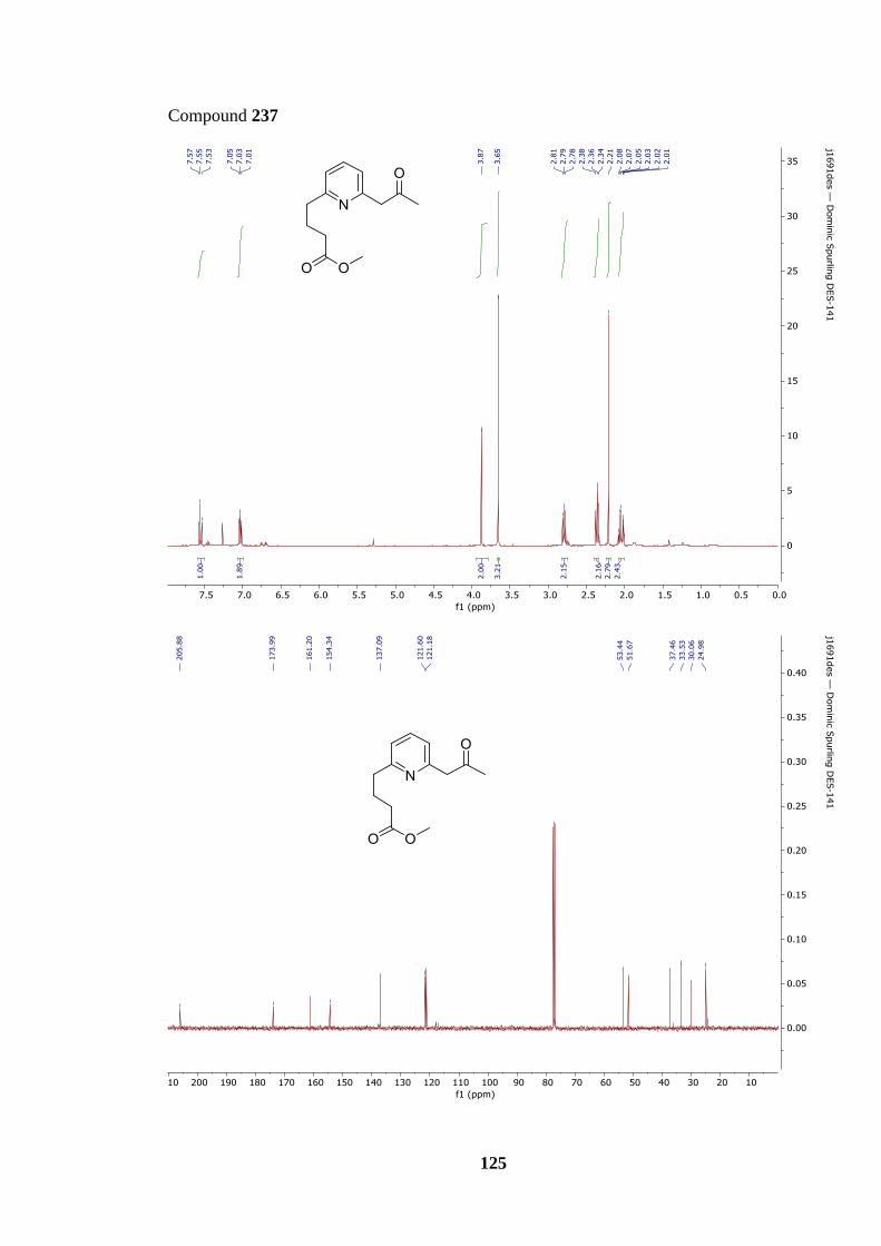
125
Compound 237

126
Abbreviations
Ac Acetyl
AIBN Azobisisobutyronitrile
a.q. Aqueous
Ar Aromatic
Bn Benzyl
bp Boiling Point
br Broad
nBu n-Butyl
tBu tert-Butyl
CAN Ceric ammonium nitrate
calcd. Calculated
CDI Carbonyl diimidazole
cm-1 Wavenumber
cod 1,5-Cyclooctadiene
COSY Correlated Spectroscopy
Cy Cyclohexyl
d Doublet
DBU 1,8-Diazabicyclo[5.4.0]undec-7-ene
DCE 1,2-Dichloroethane
dd Doublet of doublets
ddd Doublet of doublets of doublets
DCM Dichloromethane
DEAD Diethyl azodicarboxylate
DEPT Distortionless enhancement by polarization transfer
DFT Density functional theory
DIPA Diisopropylamine
DIPEA N, N-Diisopropylethylamine
DMA Dimethylacetamide
DMAP 4-Dimethylaminopyridine

127
DMF Dimethylformamide
DMSO Dimethyl sulfoxide
dppf 1,1'-Bis(diphenylphosphino)ferrocene
EDC N-(3-Dimethylaminopropyl)-N′-ethylcarbodiimide
Equiv. Equivalents
ESI Electrospray Ionisation
Et Ethyl
Fmoc Fluorenylmethoxycarbonyl
g Gram(s)
h Hour(s)
HATU Hexafluorophosphate Azabenzotriazole Tetramethyl Uronium
HMQC Heteronuclear multiple-quantum coherence
HOBt Hydroxybenzotriazole7
HRMS High resolution mass spectroscopy
Hz Hertz
hν Energy
INRE Internal nucleophile ring expansion
IR Infra-red
J Coupling constant in Hz
K Kelvin
KAPA Potassium 3-aminopropylamide
L Ligand
LDA Lithium diisopropylamide
LHMDS Lithium bis(trimethylsilyl)amide

128
M Molar
[M]+ Molecular Ion
m multiplet
m-CPBA Meta-chloroperbenzoic acid
Me Methyl
mg milligram(s)
MHz Megahertz
min Minute(s)
mL Millilitre(s)
mmol Millimole(s)
mol Mole(s)
mp Melting point
Ms Mesyl
m/z Mass to charge ratio
NMR Nuclear magnetic resonance
Ph Phenyl
Pin Pinacol
ppm Parts per million
Pyr Pyridine
P13K Phosphoinositide 3-kinase inhibitor
q Quartet
RCM Ring closing metathesis
Red-Al Sodium bis(2-methoxyethoxy)aluminium hydride
REMP Ring expansion metathesis polymerisation
Rf Retention Factor
RT Room temperature
sat. Saturated
STAB Sodium triacetoxyborohydride
SuRE Successive ring expansion

129
t Triplet
TBS tert-Butylsilane
td Triplet of doublets
Tf Triflyl
TFA Trifluoroacetic acid
THF Tetrahydrofuran
TLC Thin layer chromatography
TMS Trimethylsilane
Ts Tosyl
T3P Propylphosphonic anhydride
UV Ultra-violet
W Week(s)
XRD X-ray diffraction
9-BBN 9-Borabicyclo[3.3.1]nonane
µL Microlitre(s)
µmol Micromole(s)
δ Chemical Shift

130
References
1 A. Hussain, S. K. Yousuf and D. Mukherjee, RSC Adv., 2014, 4, 43241–43257.
2 A. Parenty, X. Moreau and J.-M. Campagne, Chem. Rev., 2006, 106, 911–939.
3 A. T. Frank, N. S. Farina, N. Sawwan, O. R. Wauchope, M. Qi, E. M. Brzostowska,
W. Chan, F. W. Grasso, P. Haberfield and A. Greer, Mol. Divers., 2007, 11, 115–118.
4 K. C. Majumdar and S. K. Chattopadhyay, Heterocycles in Natural Product Synthesis,
John Wiley & Sons, 2011.
5 J. I. Levin, Macrocycles in Drug Discovery, Royal Society of Chemistry, 2015.
6 C. Drahl, Chem. Eng. News, 2009, 87, 54–57.
7 M. R. Lambu, S. Kumar, S. K. Yousuf, D. K. Sharma, A. Hussain, A. Kumar, F. Malik
and D. Mukherjee, J. Med. Chem., 2013, 56, 6122–6135.
8 E. M. Driggers, S. P. Hale, J. Lee and N. K. Terrett, Nat. Rev. Drug Discov., 2008, 7,
608–624.
9 E. Marsault and M. L. Peterson, J. Med. Chem., 2011, 54, 1961–2004.
10 T. Ema, D. Tanida and T. Sakai, Org. Lett., 2006, 8, 3773–3775.
11 M. A. Winnik, Acc. Chem. Res., 1985, 18, 73–79.
12 L. F. Lindoy, The Chemistry of Macrocyclic Ligand Complexes, Cambridge University
Press, 1990.
13 A. K. Yudin, Chem. Sci., 2015, 6, 30–49.
14 J. Fastrez, J. Phys. Chem., 1989, 93, 2635–2642.
15 M. Malesevic, U. Strijowski, D. Bächle and N. Sewald, J. Biotechnol., 2004, 112, 73–
77.
16 K. Haas, W. Ponikwar, H. Nöth and W. Beck, Angew. Chem. Int. Ed., 1998, 37, 1086–
1089.
17 H. Fu, H. Chang, J. Shen, L. Yu, B. Qin, K. Zhang and H. Zeng, Chem. Commun.,
2014, 50, 3582–3584.
18 V. Martí-Centelles, M. D. Pandey, M. I. Burguete and S. V. Luis, Chem. Rev., 2015,
115, 8736–8834.
19 J. R. Donald and W. P. Unsworth, Chem. Eur. J., 2017, 23, 8780–8799.
20 M. Hesse, Ring enlargement in organic chemistry, VCH, Weinheim, 1991.
21 T. C. Stephens and W. P. Unsworth, Synlett, 2020, 31, 133–146.
22 U. Kramer, A. Guggisberg, M. Hesse and H. Schmid, Angew. Chem. Int. Ed. Engl.,
1977, 16, 861–862.

131
23 U. Kramer, A. Guggisberg, M. Hesse and H. Schmid, Angew. Chem. Int. Ed. Engl.,
1978, 17, 200–202.
24 L. Crombie, R. C. F. Jones, A. Rasid Mat-Zin and S. Osborne, J. Chem. Soc. Chem.
Commun., 1983, 0, 960–961.
25 H. H. Wasserman, R. P. Robinson and H. Matsuyama, Tetrahedron Lett., 1980, 21,
3493–3496.
26 B. M. Trost and J. Cossy, J. Am. Chem. Soc., 1982, 104, 6881–6882.
27 E. J. Corey, D. J. Brunelle and K. C. Nicolaou, J. Am. Chem. Soc., 1977, 99, 7359–
7360.
28 J. P. Tam, Y.-A. Lu and Q. Yu, J. Am. Chem. Soc., 1999, 121, 4316–4324.
29 L. Yet, Tetrahedron, 1999, 55, 9349–9403.
30 P. Dowd and S. C. Choi, J. Am. Chem. Soc., 1987, 109, 3493–3494.
31 W. Zhang and P. Dowd, Tetrahedron Lett., 1996, 37, 957–960.
32 G. Pattenden and D. J. Schulz, Tetrahedron Lett., 1993, 34, 6787–6790.
33 K. Prantz and J. Mulzer, Chem. Rev., 2010, 110, 3741–3766.
34 C. Fehr, J. Galindo, O. Etter and W. Thommen, Angew. Chem., 2002, 114, 4705–4708.
35 M. Ikeda, M. Takahashi, T. Uchino, K. Ohno, Y. Tamura and M. Kido, J. Org. Chem.,
1983, 48, 4241–4247.
36 G. H. Posner, M. A. Hatcher and W. A. Maio, Org. Lett., 2005, 7, 4301–4303.
37 A. P. Marchand and R. E. Lehr, Pericyclic Reactions: Organic Chemistry: A Series of
Monographs, Vol. 35.2, Academic Press, 2013.
38 E. Vedejs and J. P. Hagen, J. Am. Chem. Soc., 1975, 3.
39 R. Schmid and H. Schmid, Helv. Chim. Acta, 1977, 60, 1361–1366.
40 E. Vedejs, M. J. Mullins, J. M. Renga and S. P. Singer, Tetrahedron Lett., 1978, 19,
519–522.
41 M. H. Weston, K. Nakajima and T. G. Back, J. Org. Chem., 2008, 73, 4630–4637.
42 Y.-S. Lee, J.-W. Jung, S.-H. Kim, J.-K. Jung, S.-M. Paek, N.-J. Kim, D.-J. Chang, J.
Lee and Y.-G. Suh, Org. Lett., 2010, 12, 2040–2043.
43 E. Fouque, G. Rousseau and J. Seyden-Penne, J. Org. Chem., 1990, 55, 4807–4817.
44 R. H. Grubbs, Tetrahedron, 2004, 60, 7117–7140.
45 C. W. Lee and R. H. Grubbs, J. Org. Chem., 2001, 66, 7155–7158.
46 A. J. Boydston, Y. Xia, J. A. Kornfield, I. A. Gorodetskaya and R. H. Grubbs, J. Am.
Chem. Soc., 2008, 130, 12775–12782.
47 C. W. Lee, T.-L. Choi and R. H. Grubbs, J. Am. Chem. Soc., 2002, 124, 3224–3225.

132
48 S. S. Nadif, T. Kubo, S. A. Gonsales, S. VenkatRamani, I. Ghiviriga, B. S. Sumerlin
and A. S. Veige, J. Am. Chem. Soc., 2016, 138, 6408–6411.
49 M. H. Shaw and J. F. Bower, Chem. Commun., 2016, 52, 10817–10829.
50 C. Li, H. Zhang, J. Feng, Y. Zhang and J. Wang, Org. Lett., 2010, 12, 3082–3085.
51 O. Boyd, G.-W. Wang, O. O. Sokolova, A. D. J. Calow, S. M. Bertrand and J. F.
Bower, Angew. Chem. Int. Ed., 2019, 58, 18844–18848.
52 M. Murakami, T. Tsuruta and Y. Ito, Angew. Chem. Int. Ed., 2000, 39, 2484–2486.
53 C. Kitsiou, J. J. Hindes, P. I’Anson, P. Jackson, T. C. Wilson, E. K. Daly, H. R.
Felstead, P. Hearnshaw and W. P. Unsworth, Angew. Chem. Int. Ed., 2015, 54, 15794–
15798.
54 L. G. Baud, M. A. Manning, H. L. Arkless, T. C. Stephens and W. P. Unsworth,
Chem. – Eur. J., 2017, 23, 2225–2230.
55 T. C. Stephens, M. Lodi, A. M. Steer, Y. Lin, M. T. Gill and W. P. Unsworth, Chem. –
Eur. J., 2017, 23, 13314–13318.
56 T. C. Stephens, A. Lawer, T. French and W. P. Unsworth, Chem. – Eur. J., 2018, 24,
13947–13953.
57 A. Lawer, J. A. Rossi‐Ashton, T. C. Stephens, B. J. Challis, R. G. Epton, J. M. Lynam
and W. P. Unsworth, Angew. Chem., 2019, 131, 14080–14085.
58 S. R. LaPlante, L. D. Fader, K. R. Fandrick, D. R. Fandrick, O. Hucke, R. Kemper, S.
P. F. Miller and P. J. Edwards, J. Med. Chem., 2011, 54, 7005–7022.
59 E. Vitaku, D. T. Smith and J. T. Njardarson, J. Med. Chem., 2014, 57, 10257–10274.
60 J. Clegg, Masters Dissertation, University of York, 2020.
61 T. Stephens, PhD, University of York, 2019.
62 Coronavirus, https://www.who.int/emergencies/diseases/novel-coronavirus-2019,
(accessed 27 April 2020).
63 H. Kroth, N. Sreenivasachary, A. Hamel, P. Benderitter, Y. Varisco, V. Giriens, P.
Paganetti, W. Froestl, A. Pfeifer and A. Muhs, Bioorg. Med. Chem. Lett., 2016, 26,
3330–3335.
64 D. Duran, N. Wu, B. Mao and J. Xu, J. Liq. Chromatogr. Relat. Technol., 2006, 29,
661–672.
65 J. Kim, Y. Ohk, S. H. Park, Y. Jung and S. Chang, Chem. Asian J., 2011, 6, 2040–
2047.
66 H. Tsukamoto and Y. Kondo, Org. Lett., 2007, 9, 4227–4230.

133
67 T. Yokoi, H. Tanimoto, T. Ueda, T. Morimoto and K. Kakiuchi, J. Org. Chem., 2018,
83, 12103–12121.
68 D. Basavaiah, G. C. Reddy and K. C. Bharadwaj, Eur. J. Org. Chem., 2014, 2014,
1157–1162.
69 G. J. Lovinger and J. P. Morken, J. Am. Chem. Soc., 2017, 139, 17293–17296.
Related Documents


