The University of Reading Multi-Finger Manipulation Physics for Haptic Rendering Nic Melder January 2011 Submitted for the degree of PhD in Cybernetics Department of Cybernetics, School of Systems Engineering, The University of Reading

Welcome message from author
This document is posted to help you gain knowledge. Please leave a comment to let me know what you think about it! Share it to your friends and learn new things together.
Transcript

The University of Reading
Multi-Finger Manipulation Physics for Haptic
Rendering
Nic Melder
January 2011
Submitted for the degree of PhD in Cybernetics
Department of Cybernetics, School of Systems Engineering,
The University of Reading

Declaration
I confirm that this is my own work and the use of all material from other sources has
been properly and fully acknowledged.
Nic Melder
10 January 2011

Acknowledgements
I would like to express my gratitude to Professor William Harwin for his patient
guidance, intense criticism and deep insight into the discussions that have formed the
basis of this thesis.
I would also like to express my gratitude to Dr William Browne and his wife Lydia,
Dr Rui Louriero and his wife Sylvia and Dr Max Bingham for their support (and more
importantly their spare rooms) throughout the years whilst I was writing this thesis.
Finally, I would like to thank the EPSRC for their funding of the “Haptic cues in
multi-point interactions with virtual and remote objects” project which made this
research possible,
Abstract
Computer haptics has the potential to greatly enhance the way that humans interact
with computers especially when a 3D representation of the data is possible. However,
the majority of 3D haptic systems in use are single point of contact systems where the
user interacts through a stylus. By using multiple fingers and a reasonable physics
model of the world, interaction within this virtual world can be made more intuitive as
the user can now reach into the world and directly manipulate it instead of just
prodding and poking it. In this thesis, methods are described that allow a virtual 3D
object to be manipulated with multiple contact points. This includes lifting an object
from a surface, rotating and moving it in free space, and placing it back down on a
surface. The Friction Cone Algorithm and the Residual Force and Torque Algorithms
are presented that allow for this type of manipulation.
The Friction Cone Algorithm is a mechanism that allows an arbitrarily complex
friction model to be simulated on a variety of different 3D object representations
including polygon meshes, parametric objects, NURBS surfaces and CSG trees. The
Residual Force and Torque Algorithms are able to convert the residual forces and
torques of an object into a translational and rotational component that can be used to
reposition and reorient the object. A method to allow object rotation between contact
points is also given as well as a method to calibrate multiple haptic devices to the
same co-ordinate frame. The software structure of the implemented multi-point
haptic system is described including the multi-point haptic specific features that were
incorporated as well as details of all the collision methods that were developed to
allow for multi-object haptic collisions to be simulated.
Due to the subjective nature of haptic rendering, a number of user evaluations are
given to show the flexibility of the algorithms, the software system and the realism
that was achieved. The evaluations include user observations whilst using the system
as well as the results of psychophysical experiments that were conducted using the
developed algorithms. These observations show that the system is both intuitive to
use as well as being a good representation of the real world.

Contents
1 Thesis Aims and Overview ...........................................................................................................1
2 Introduction to Haptics ................................................................................................................5
2.1 What is Haptics? ...................................................................................................................5
2.2 The Physiology of Touch .......................................................................................................7
2.2.1 The Cutaneous Haptic Sense ............................................................................................7
2.2.2 The Kinaesthetic Haptic Sense .........................................................................................9
2.3 The Psychology and Perception of Touch ...........................................................................10
2.3.1 Exploratory procedures...................................................................................................11
2.3.2 Sense Dominance, Illusions and Effects .........................................................................13
2.3.3 The Size-Weight and Grasp Span Weight Illusion .........................................................15
2.4 Haptics and Virtual Reality .................................................................................................15
2.5 Haptic Interfaces .................................................................................................................16
2.5.1 Terminology and Definitions Used to Describe Haptic Interfaces .................................19
2.5.2 Constrained Motion Haptic Devices...............................................................................21
2.5.3 Control Strategies for Constrained Motion Devices .......................................................28
2.5.4 Tactile Displays ..............................................................................................................29
2.5.5 Perceptual Effects Caused by Haptic Devices ................................................................31
2.6 Hand Grasps and Multi-Finger Haptics..............................................................................32
2.6.1 Types of Hand Grasp ......................................................................................................33
2.6.2 Multi-Finger Haptic Systems..........................................................................................35
2.7 Applications.........................................................................................................................36
2.8 Current Limitations of Haptic Devices................................................................................39
2.9 Haptic Software Components ..............................................................................................40
2.9.1 Device Interface..............................................................................................................41
2.9.2 Collision Detection .........................................................................................................41
2.9.3 Contact Response............................................................................................................41
2.9.4 Object Database..............................................................................................................42
2.9.5 Physics Engine................................................................................................................42
2.10 Chapter Summary................................................................................................................42
3 Physical Modelling and Rendering Methods ............................................................................44
3.1 Current Haptic and Visual Rendering Methods ..................................................................44
3.1.1 Visual vs Haptic Rendering ............................................................................................45

3.1.2 Single Point Haptic Rendering Methods.........................................................................45
3.1.3 Multi-Point Haptic Rendering ........................................................................................50
3.2 Friction................................................................................................................................52
3.2.1 Friction Models and Friction Modelling.........................................................................52
3.2.2 Friction Implementations................................................................................................54
3.3 Hand Grasps and Object Manipulation Physics .................................................................55
3.3.1 Residual Force Resolution ..............................................................................................56
3.4 Properties of Virtual Objects...............................................................................................57
3.4.1 Storage Methods for Position and Orientation................................................................57
3.5 Collision Detection..............................................................................................................58
3.5.1 Types of Collision...........................................................................................................59
3.5.2 Optimisations for Collision Detection ............................................................................60
3.6 Chapter Summary................................................................................................................61
4 Implementing Friction................................................................................................................63
4.1 The Friction Cone Algorithm on a Plane ............................................................................64
4.1.1 Modelling Static, Dynamic and Viscous Friction...........................................................67
4.1.2 Modelling Arbitrarily Complex Friction Models............................................................68
4.2 Applying the Friction Cone Algorithm to Polygon Meshes and Curved Surfaces...............68
4.2.1 Simple Parametric Objects..............................................................................................69
4.2.2 Single NURBS surfaces..................................................................................................71
4.2.3 Polygon Meshes..............................................................................................................71
4.2.4 Crossing Polygon Boundaries.........................................................................................75
4.2.5 The Friction Cone Algorithm on an Edge.......................................................................78
4.2.6 Smoothing Polygon Transitions Using Force Shading ...................................................79
4.2.7 Height Mapping..............................................................................................................83
4.3 Chapter Summary................................................................................................................83
5 Multi-Finger Manipulation Physics...........................................................................................85
5.1 Possible Types of Grasp with the Hardware Used ..............................................................85
5.1.1 Types of Grasps ..............................................................................................................86
5.2 Calibration of Multiple Discrete Devices............................................................................87
5.3 Manipulating Objects - The Residual Force and Torque Algorithms .................................89
5.3.1 The Residual Force and Torque Algorithms...................................................................90
5.3.2 Analysis of the Rotation Method ....................................................................................92
5.3.3 Two Finger Grasps and Soft Finger Contact Modelling.................................................93
5.3.4 Single Finger Contact Grasps .........................................................................................95
5.4 Chapter Summary................................................................................................................96
6 Interactions Between Objects and their Environment ............................................................98
6.1 Types of Interaction.............................................................................................................98
6.1.1 Non-Haptic Object Interactions ......................................................................................99
6.1.2 Haptic Object with Fixed Object Interactions.................................................................99
6.1.3 Haptic Object with Dynamic Object Interactions ...........................................................99
6.2 Picking and placing objects...............................................................................................100
6.2.1 Contact Determination..................................................................................................100
6.2.2 Contact Response..........................................................................................................101
6.2.3 Rotate Down Behaviour ...............................................................................................103
6.2.4 Rotate Up Behaviour ....................................................................................................105
6.3 Feeling objects with other objects .....................................................................................106
6.3.1 Volumetric Fingers .......................................................................................................106
6.4 Chapter Summary..............................................................................................................108
7 Phantom3 - The Haptic Software Application........................................................................109
7.1 Application Architecture ...................................................................................................109
7.1.1 Features and Requirements of the Phantom3 Application............................................110
7.1.2 General Application Architectural Design....................................................................111
7.2 The Systems and Sub-Systems of Phantom3 ......................................................................112
7.2.1 Entities vs Objects ........................................................................................................113
7.2.2 Application ...................................................................................................................113
7.2.3 Loading System ............................................................................................................113
7.2.4 Object Factory / Database.............................................................................................116
7.2.5 Database Objects ..........................................................................................................116
7.2.6 Entities ..........................................................................................................................117
7.2.7 Entity Managers............................................................................................................120
7.2.8 Render Device ..............................................................................................................121
7.2.9 User Interface Manager ................................................................................................121
7.2.10 Collision Engine ......................................................................................................121
7.2.11 Physics Engine .........................................................................................................122
7.2.12 Input Manager..........................................................................................................122
7.3 Threading Strategy and Application Process Flow...........................................................123
7.4 Collision Detection Implementation..................................................................................126
7.4.1 Point - Plane Intersection..............................................................................................127
7.4.2 Point - Sphere Intersection............................................................................................128
7.4.3 Point - Cylinder Intersection.........................................................................................128

7.4.4 Point - Torus Intersection .............................................................................................131
7.4.5 Point - Polygon Intersection .........................................................................................132
7.4.6 Sphere – Object Intersections .......................................................................................135
7.4.7 Lozenges, Pebbles, and other Scaled Objects ...............................................................137
7.5 Implementation Specifics...................................................................................................138
7.5.1 Integrators.....................................................................................................................138
7.5.2 User Space vs Kernel Space .........................................................................................138
7.5.3 Stick-Slip Friction Modelling .......................................................................................138
7.5.4 Polygon Transitioning ..................................................................................................139
7.6 Chapter Summary..............................................................................................................140
8 Results, Case Histories and User Applications .......................................................................141
8.1 Experimental Results .........................................................................................................141
8.2 Case Histories ...................................................................................................................146
8.2.1 Case History 1 ..............................................................................................................146
8.2.2 Case History 2 ..............................................................................................................147
8.2.3 Case History 3 ..............................................................................................................147
8.2.4 Case History 4 ..............................................................................................................147
8.2.5 Case History 5 ..............................................................................................................149
8.2.6 Case History 6 ..............................................................................................................149
8.3 User Applications ..............................................................................................................149
8.3.1 The Psychological Perception Experiments..................................................................150
8.3.2 Exploring Haptics in Immersive CAVE Type VR........................................................153
8.3.3 Creating Impossible Objects.........................................................................................154
8.3.4 The Small Creature Veterinary Prototype.....................................................................155
8.3.5 The Electromyogram (EMG) / Reach and Grasp Data Recorder..................................156
8.3.6 The Virtual Shopping Experience.................................................................................156
8.4 Perceptual Results .............................................................................................................156
8.5 Chapter Summary..............................................................................................................157
9 Discussions, Further Work and Conclusions..........................................................................159
9.1 Discussion .........................................................................................................................159
9.2 Further Work.....................................................................................................................164
9.3 CSG Rendering with the Friction Cone Algorithm............................................................165
9.3.1 CSG Boundary Transitions...........................................................................................167
9.3.2 Discussion of the Proposed CSG Rendering Method ...................................................172
9.4 Design Decisions and Features for Phantom3 Version 2..................................................173

9.5 Thesis Conclusion..............................................................................................................175
10 References..................................................................................................................................178
Appendix A - Published Papers.........................................................................................................201
1
1 Thesis Aims and Overview
The aim of this thesis is to explore the computational and engineering methods that
allow multi-finger manipulation of virtual objects using haptic interfaces. Since
multi-finger manipulation is synonymous with grasping and holding it is desired that
this is achieved in a way that is as close to the real world as possible. This thesis
describes the software methods that have been developed in order to achieve these
goals.
Chapter 2 provides the non-physics/engineering background to the field of haptics.
The aim of this chapter is to introduce the reader to what haptics is, the physiological
structures in the human body that make up our haptic system and the psychology of
haptic perception. The different types of haptic devices are also detailed along with
their advantages and disadvantages as well as the different control methodologies that
are used to control them. The different types of grasp are introduced along with
multi-finger haptics and how it differs from single finger haptics, the specific
problems associated with it and the particular benefits of it. Chapter 2 concludes with
the current applications and limitations of haptics and the software components
required to create a complete haptic system.
Chapter 3 provides the technical background relevant to the field of haptic rendering
and object manipulation. The requirements for the successful implementation of a
haptic enabled physical simulation are defined along with the current haptic rendering
methods that already exist. Since this thesis is concerned with object manipulation,
different friction models and the current implementation of friction is also described.
Similarly, the required physical properties of an object as well as the physics of
grasping and manipulation are detailed. Given that an important aspect of haptic
rendering is the initial contact with an object, this chapter concludes with an
explanation of the requirements for haptic collision detection as well as various
techniques that optimise the determination of a collision.
Chapters 4, 5 and 6 detail the new methods that have been developed to allow for the
successful multi-finger manipulation of virtual objects. Chapter 4 presents the

Chapter 1: Thesis Aims and Overview
2
Friction Cone Algorithm, a novel way of modelling friction that has been developed
specifically for haptic contacts and multi-contact haptic systems. Since the Friction
Cone Algorithm is not a friction model but a mechanism to allow different friction
models to be haptically rendered, details are given how an arbitrarily complex friction
model can be implemented. The application of the Friction Cone Algorithm to
various 3D object representations is also given. This includes simple parametric
objects, single NURBS surfaces and complex polygon meshes. For polygon meshes,
Face Directed Connection Graphs are developed that aids in the transition from one
face to another across an edge. How the Friction Cone Algorithm works on an edge is
also described. Analogous to graphical Phong shading and bump mapping, force
shading and height mapping are also described as a means to smooth the feel of
polygon edges as well as to simulate bumpy surfaces.
Chapter 5 is concerned with multi-finger manipulation of virtual objects. Due to the
hardware available only single finger, two finger and three finger precision grips were
possible; it was not possible to model any of the power grasps. Since the hardware
consisted of three discrete devices, a method to calibrate them all to the same work
space is given. This ensures that all the forces that are applied to a contacted object
and rendered to the user via the haptic devices are presented in the correct direction.
These forces can then be input to a suitable movement algorithm allowing the object
to be manipulated. The Residual Force / Torque Algorithms are presented which
converts the applied force and torque generated by multiple points of contact into a
new position and orientation for the object. With only two points of contact, the
simulation of torsional friction is desirable as this allows an object to be allowed to
rotate between the fingers due to any simulated gravity. This ‘soft finger contact
modelling’ is presented and it is shown how it can be easily achieved when using the
Friction Cone Algorithm. To conclude, the different single finger grasps are also
presented.
Whereas Chapters 4 and 5 were concerned with direct haptic interactions, i.e. the
virtual haptic endpoint interacting with a virtual object, Chapter 6 is concerned with
how virtual manipulated objects should behave when they collide with other virtual
objects. The ability to pick up and place an object in a natural manner is essential for
realistic object manipulation and the various methods to achieve this are explored

Chapter 1: Thesis Aims and Overview
3
here. The different types of object-object interactions are presented, although this
chapter is only concerned with grasped object to non-moveable object interactions.
There are two ways in which object-object interaction can be solved: force based or
impulse based. Due to the similarities to how the Friction Cone Algorithm works,
only the force based solution is considered. Picking up and placing a cube from / onto
a plane is used to describe the different stages that the object will move through as it
is placed on the surface and comes to rest or is lifted up and becomes suspended. This
chapter concludes with how a grasped object can be used to ‘feel’ another object and
how this can be applied to allow a ‘haptic volumetric finger’ to replace the haptic
interaction point.
Chapter 7 details the software architecture of Phantom 3, the application that was
created when developing the Friction Cone Algorithm and the Residual Force /
Torque Algorithms. The collisions detection algorithms developed are also detailed
and some implementation details specific to haptic systems and, in particular, the
Friction Cone Algorithm are also given.
Since the research in this thesis has been in developing haptic rendering methods,
when applying the algorithms with sensible parameters whilst using a suitable device,
object manipulation will either feel natural or it won’t. This is not binary but is instead
more of a scale of realism. The realism of the system can be destroyed such as if the
system exhibits a large inertial mass which will limit the maximum achievable
acceleration, if the maximum velocity that can be achieved is too slow or if there is a
soft representation of hard contact. Chapter 8 presents both experimental results and
subjective results to help to illustrate the robustness, realism and intuitiveness of the
developed algorithms and system. The results of two psychophysical perception tests,
conducted by McKnight but using the presented algorithms, are also given. A number
of different applications were also developed throughout the development of the
Friction Cone and Residual Force / Torque Algorithms and these are also presented
here as an example of the flexibility of the developed system and algorithms.
In conclusion, Chapter 9 discusses the developed algorithms, suggests areas where
this research can be extended into, including a detailed explanation of how the
Friction Cone Algorithm can be used to render constructive solid geometries, and also

Chapter 1: Thesis Aims and Overview
4
describes some of the problems that occurred during the development of the
Phantom3 application framework. This chapter concludes with a short summary of
the contributions that this thesis makes to the field of haptics as well as the advantages
that the developed algorithms posses over previous haptic rendering algorithms.

Chapter 2: Introduction to Haptics
5
2 Introduction to Haptics
2.1 What is Haptics?
Haptics is the study of human touch and interaction within an environment. The
Oxford English Dictionary defines haptics as:
haptic, a. (and n.) – Of pertaining to, or relating to the sense of touch or
tactile sensations. b. Having a greater dependence on sensations of
touch than on sight, esp. as a means of psychological orientation. Also
absol., a haptic person.
So ‘haptical a., ‘haptically adv,; ‘haptics Psychol. and Linguistics, the
study of touch and tactile sensations, esp. as a means of
communication.’ [wwwOED05]
The word haptic first appeared in the Billings medical dictionary in 1890 and the
word haptics was first used by M. Dessoir in 1892. It takes its etymology from the
greek haptikos meaning able to come into contact with. An alternative definition
given by Gibson describes haptics as:
‘The sensibility of the individual to the world adjacent to his body by the
use of his body’ [Gibson66]
Of the five human senses touch is unique in that it is both used to gather information
about the environment as well as to directly affect it. We use our sense of touch to
learn about properties of an object, i.e. is it hot or cold, light or heavy, rough or
smooth, as well as to directly manipulate the same object. Information received by
our haptic sense can be further classified into two categories: cutaneous stimulation
and kinaesthetic stimulation. Cutaneous stimulation is detected through the
mechanoreceptors in the skin and is primarily a means of relaying surface details such
as surface texture. Temperature and pain are also measured through similar receptors.
In contrast, kinaesthetic information is used to understand large scale details such as

Chapter 2: Introduction to Haptics
6
object shape and weight and this is achieved via feedback from the muscular and
skeletal system [Loomis86].
In the context of computer based haptics, haptics relates to the science, technology
and applications associated with information acquisition and object manipulation
through touch, in particular where that touch is mediated via some type of haptic
interface. An early use of haptic interfaces was Project Grope [Brooks90]. It was
started in 1967 and was developed to assist in molecular docking applications for drug
development.
The purpose of this chapter is to introduce haptics, haptic interfaces and computer
haptic systems to the reader. It provides the background into the physiology and
psychology of what haptics is and how it is perceived as well as the different types of
hardware that has been developed in order to stimulate our haptic sense. Multi-finger
haptics is introduced to show how it differs from single finger haptics, the current
applications that computer haptic systems are used in and the necessary software
components of a typical computer haptic system are also described. This chapter
concludes with the aims of the research presented in this thesis.

Chapter 2: Introduction to Haptics
7
2.2 The Physiology of Touch
2.2.1 The Cutaneous Haptic Sense
Figure 2.1: A cross section through the skin showing the relative position of the different
mechanoreceptors found in both the hairy and glabrous skin [wwwSkin07].
There are four different types of skin covering the human body: hairy skin, glabrous
skin (skin without hair e.g. the finger tips), the mucous membranes (lining the inside
of body orifices) and mucocutaneous skin (where the mucous membranes meet hairy
skin, eg. the lips). Each of these different skin types perform different functions and
contain different types and densities of receptors embedded in them. In relation to the
study of haptics relating to virtual reality, it is the glabrous skin that is most used as it
covers the fingertips and palm of the hand.
There are four main types of mechanoreceptive nerve endings under the skin that
facilitate tactile perception [Bolanowski88] [Cholewiak91]. These are the Meissner
corpuscles, Merkel disks, Pacinian corpuscles and Ruffini endings. They can be
functionally categorised based upon their receptive fields (small (Type I) or large
(Type II)) and their temporal properties (rapidly adapting (RA) and slowly adapting
(SA)). Rapidly adapting receptors have little or no static response activating only as
long as the stimulus is in motion; they sense skin stretch and vibration. In contrast to
this, slowly adapting receptors are sensitive to dynamic stimuli but also exhibit a

Chapter 2: Introduction to Haptics
8
response dependant upon the amplitude of any maintained skin indentation; they sense
compressive stress and directional skin stretch. It is believed that RAI receptors
correspond to the Meissner corpuscles, RAII receptors to the Pacinian corpuscles, SAI
receptors to the Merkel disks and SAII receptors to the Ruffini endings.
Table 2.1 shows the different mechanoreceptors in the skin of the glabrous human
hand [Kontarinis93] [Johansson82]. The frequency range within all types of
mechanoreceptor increases rapidly with the amplitude of the stimulus.
Receptor
Type
Receptive Field (mm2)
(median)
Frequency Range (most
sensitive)
Amplitude
Threshold (µm)
RAI 1-100 (12.6) 10-200Hz (20-40Hz) 30
SAI 2-100 (11.0) 0.4-100Hz (7Hz) 15
RAII 10-1000 (100) 40-800Hz (200-300Hz) 1
SAII 10-500 (60) 7Hz 60
Table 2.1: Properties of the mechanoreceptors in the glabrous human hand [Kontarinis93]
[Johansson82]. The receptive field gives an approximation of the area around the receptor that will
cause it to respond given an appropriate stimulus. This stimulus must be within the frequency range
presented with the minimum amplitude as given by the amplitude threshold. It should be noted that all
the values stated are good approximations and not absolute values.
Due to the different temporal and spatial responses of the various mechanoreceptors,
different types of sensations are perceived through each or a combination of the
mechanoreceptors. The RAII receptors have a maximum response in the region of
250Hz and hence serve to detect vibratory signals such as caused by stroking fine
surfaces or when an object is initially contacted. In contrast, the SAI receptors are
active in the perception of patterns pressed into the skin such as Braille symbols
[Phillips90]. These same receptors also appear to mediate the perception of roughness
when surfaces have raised elements separated by about 1mm or more [Connor92].
Other cutaneous receptors include thermal receptors and pain receptors (nociceptors).
Thermal sensation is mediated by separate receptors that detect heat and cold. Warm
receptors begin firing when the skin temperature rises above 30 °C, and increase their
firing rate as the temperature reaches 45 °C. Cold receptors fire when the skin
Chapter 2: Introduction to Haptics
9
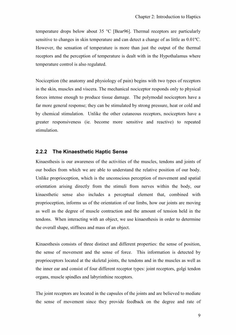
temperature drops below about 35 °C [Bear96]. Thermal receptors are particularly
sensitive to changes in skin temperature and can detect a change of as little as 0.01ºC.
However, the sensation of temperature is more than just the output of the thermal
receptors and the perception of temperature is dealt with in the Hypothalamus where
temperature control is also regulated.
Nociception (the anatomy and physiology of pain) begins with two types of receptors
in the skin, muscles and viscera. The mechanical nociceptor responds only to physical
forces intense enough to produce tissue damage. The polymodal nociceptors have a
far more general response; they can be stimulated by strong pressure, heat or cold and
by chemical stimulation. Unlike the other cutaneous receptors, nociceptors have a
greater responsiveness (ie. become more sensitive and reactive) to repeated
stimulation.
2.2.2 The Kinaesthetic Haptic Sense
Kinaesthesis is our awareness of the activities of the muscles, tendons and joints of
our bodies from which we are able to understand the relative position of our body.
Unlike proprioception, which is the unconscious perception of movement and spatial
orientation arising directly from the stimuli from nerves within the body, our
kinaesthetic sense also includes a perceptual element that, combined with
proprioception, informs us of the orientation of our limbs, how our joints are moving
as well as the degree of muscle contraction and the amount of tension held in the
tendons. When interacting with an object, we use kinaesthesis in order to determine
the overall shape, stiffness and mass of an object.
Kinaesthesis consists of three distinct and different properties: the sense of position,
the sense of movement and the sense of force. This information is detected by
proprioceptors located at the skeletal joints, the tendons and in the muscles as well as
the inner ear and consist of four different receptor types: joint receptors, golgi tendon
organs, muscle spindles and labyrinthine receptors.
The joint receptors are located in the capsules of the joints and are believed to mediate
the sense of movement since they provide feedback on the degree and rate of

Chapter 2: Introduction to Haptics
10
angulation (change in position) of joint. The muscle spindles and golgi tendon organs
provide feedback directly related to the muscles. The muscle spindles are located
between the individual fibres throughout the muscle and are excited by the stretching
of the neighbouring muscle fibres. They also can determine the rate of increase in the
muscle length (stretch). The golgi tendon organs are located at the junction between
the muscle and the tendon and they sense the tension applied to the tendon. As the
degree of tension is related to the degree of muscle contraction, the golgi tendon
organs act as localised tension detectors, regulating muscle co-contraction which is an
important aspect in fine motor control. The labyrinthine receptors are associated with
the inner ear and our sense of balance and are therefore not related to our haptic
physiology.
In addition to the above sensory equipment, kinaesthetic sensing may also be provided
by the cutaneous mechanoreceptors due to skin stretch associated with the body’s
motion.
2.3 The Psychology and Perception of Touch
Figure 2.2: The Sensory Homunculus (latin for little man) is a representative model of the human
body where the size of each part is proportional to the amount of ‘brain power’ that is dedicated to
processing it [Penfield37]. It can be seen that the hands are much larger than the arms and this is due to
the much higher density of receptors in the hands compared to the arms [wwwHomunc09].

Chapter 2: Introduction to Haptics
11
Although intimately related, sensation and perception play two complimentary but
different roles in how we interpret our world. Sensation refers to the process of
sensing our environment through touch, taste, sight, sound, and smell. Perception is
the way we interpret these sensations and therefore make sense of everything around
us.
The raw data received from the haptic sensory system is processed in the brain in the
somatosensory cortex, also known as the primary sensory cortex. It has been shown
that stimulation of different areas of the body affect different parts of the
somatosensory cortex and in different amounts. The sensory homunculus (see Figure
2.2) shows how much of the human brain is devoted to processing the sensory data
received from the body. It can be seen that the hands and feet are comparatively large
when compared with the rest of the body and this is due to a comparatively high
receptor distribution density in these places. It is not surprising that the hands are
large since of all the parts of the body we use our hands to explore the world and the
objects around us.
2.3.1 Exploratory procedures
When trying to determine a property of an object it is usual to adopt a particular
pattern of movements e.g. stroking or a rubbing a surface (i.e. producing motion
between the fingertip and a contacted surface) is a means to determine the roughness
of an object. Lederman and Klatzky [Lederman87] proposed a series of exploratory
procedures which associates an action with an object property. An exploratory
procedure is typically used when trying to determine the associated property and it is
the optimal method (in terms of speed and/or accuracy) to extract information about
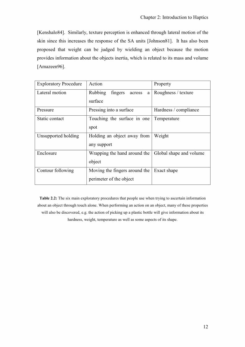
that property. Table 2.2 and Figure 2.3 detail the main exploratory procedures
described by Lederman and Klatzky.
The exploratory procedures appear to maximise the appropriate sensory stimulation
for the property under investigation. For example, to determine the temperature of an
object, using static contact characteristically involves a large skin surface contact area.
This larger area allows the production of a summated signal from the spatially
distributed thermal receptors since more thermal receptors are likely to be affected
Chapter 2: Introduction to Haptics
12
[Kenshalo84]. Similarly, texture perception is enhanced through lateral motion of the
skin since this increases the response of the SA units [Johnson81]. It has also been
proposed that weight can be judged by wielding an object because the motion
provides information about the objects inertia, which is related to its mass and volume
[Amazeen96].
Exploratory Procedure Action Property
Lateral motion Rubbing fingers across a
surface
Roughness / texture
Pressure Pressing into a surface Hardness / compliance
Static contact Touching the surface in one
spot
Temperature
Unsupported holding Holding an object away from
any support
Weight
Enclosure Wrapping the hand around the
object
Global shape and volume
Contour following Moving the fingers around the
perimeter of the object
Exact shape
Table 2.2: The six main exploratory procedures that people use when trying to ascertain information
about an object through touch alone. When performing an action on an object, many of these properties
will also be discovered, e.g. the action of picking up a plastic bottle will give information about its
hardness, weight, temperature as well as some aspects of its shape.
Chapter 2: Introduction to Haptics
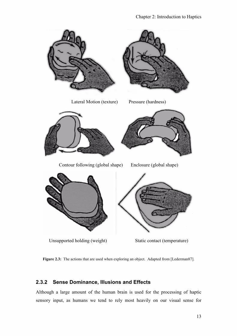
13
Lateral Motion (texture) Pressure (hardness)
Contour following (global shape) Enclosure (global shape)
Unsupported holding (weight) Static contact (temperature)
Figure 2.3: The actions that are used when exploring an object. Adapted from [Lederman87].
2.3.2 Sense Dominance, Illusions and Effects
Although a large amount of the human brain is used for the processing of haptic
sensory input, as humans we tend to rely most heavily on our visual sense for

Chapter 2: Introduction to Haptics
14
information. In fact, when there is a disparity between our visual sense and another
sense, we will always assume that what we see is correct and it is our other sense that
is at fault, hence the phrase “seeing is believing”. In general, vision is the most
dominant of our senses but there are situations where this is not the case. Ernst et al
[Bresciani05] [Ernst04] showed that audio was dominant when trying to determine the
number of visual flashes or tactile taps if the subject was also presented with a
different number of audio beeps simultaneously. It has also been suggested that we
use our haptic sense to calibrate our visual sense, especially when interacting in
virtual environments [Rock64] although more recently this has come into dispute
[Helbig08].
It is commonly believed that vision, hearing and touch are entirely separate
‘perceptual modules’, each operating independently to provide us with unique
information about the external world. Recent studies, however, have revealed that our
perceptual experience is in fact shaped by a multitude of complex interactions
between sensory modalities. A number of powerful multi-sensory illusions
demonstrate that the senses are inextricably linked, and that our perception of visual,
auditory or tactile events can be altered dramatically by information from other
senses.
When a sound is accompanied by a visual stimulus at another location, people tend to
perceive this sound incorrectly at the same position as the visual stimulus. This is
known as the ventriloquism effect [Bertelson98]. Similarly, if a person sees a life
sized rubber model of a hand where they would normally expect to see their real hand
(which is hidden from view), the person will experience a touch on the rubber hand as
though it were their own. This occurs even if the artificial hand’s appearance greatly
differs from the user’s real hand. In fact, the illusion is so strong that it still works if
the fake hand is non-human [Botvinick98]. In Botvinick’s experiment, 10 subjects
were seated with their left arm resting on the table with a standing screen positioned
to hide their arm. A life sized rubber model arm was then placed on the table in front
of the subjects and a light stroke of a paint brush was drawn on the real and fake arm
simultaneously. Questioning at the end of the experiment indicated that the subjects
experienced an illusion in which they seemed to feel the touch not of the hidden brush
but that of the viewed brush, as if the rubber hand had sensed the touch.
Chapter 2: Introduction to Haptics
15
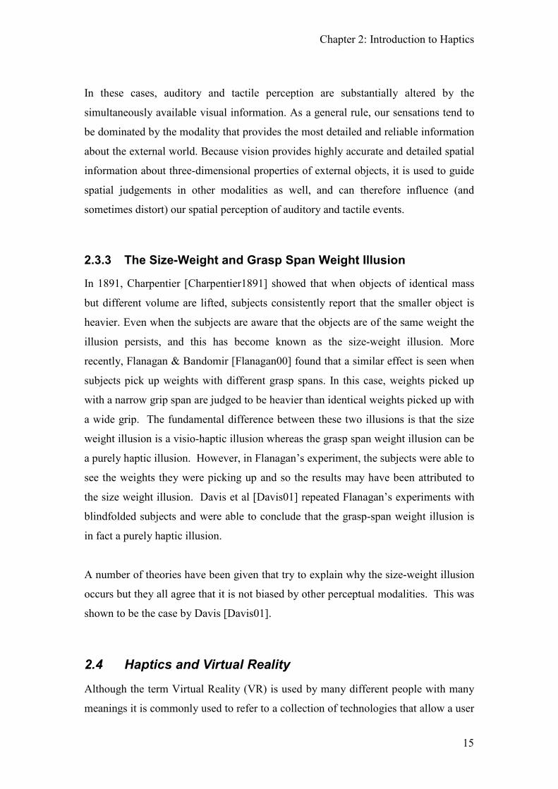
In these cases, auditory and tactile perception are substantially altered by the
simultaneously available visual information. As a general rule, our sensations tend to
be dominated by the modality that provides the most detailed and reliable information
about the external world. Because vision provides highly accurate and detailed spatial
information about three-dimensional properties of external objects, it is used to guide
spatial judgements in other modalities as well, and can therefore influence (and
sometimes distort) our spatial perception of auditory and tactile events.
2.3.3 The Size-Weight and Grasp Span Weight Illusion
In 1891, Charpentier [Charpentier1891] showed that when objects of identical mass
but different volume are lifted, subjects consistently report that the smaller object is
heavier. Even when the subjects are aware that the objects are of the same weight the
illusion persists, and this has become known as the size-weight illusion. More
recently, Flanagan & Bandomir [Flanagan00] found that a similar effect is seen when
subjects pick up weights with different grasp spans. In this case, weights picked up
with a narrow grip span are judged to be heavier than identical weights picked up with
a wide grip. The fundamental difference between these two illusions is that the size
weight illusion is a visio-haptic illusion whereas the grasp span weight illusion can be
a purely haptic illusion. However, in Flanagan’s experiment, the subjects were able to
see the weights they were picking up and so the results may have been attributed to
the size weight illusion. Davis et al [Davis01] repeated Flanagan’s experiments with
blindfolded subjects and were able to conclude that the grasp-span weight illusion is
in fact a purely haptic illusion.
A number of theories have been given that try to explain why the size-weight illusion
occurs but they all agree that it is not biased by other perceptual modalities. This was
shown to be the case by Davis [Davis01].
2.4 Haptics and Virtual Reality
Although the term Virtual Reality (VR) is used by many different people with many
meanings it is commonly used to refer to a collection of technologies that allow a user

Chapter 2: Introduction to Haptics
16
to interact with a computer generated/simulated environment. In this context,
probably the best definition of Virtual Reality is given by Aukstakalnis:
“Virtual Reality is a way for humans to visualize, manipulate and
interact with computers and extremely complex data” [Aukstakalnis92]
Visualisation refers to the manner in which the complex data is presented to the user
and may be visual, auditory, haptic or any other sensory stimulation. Manipulation
and interaction is also an important aspect of virtual reality as without the ability to
interact and affect a change, a person can not feel that they are a part of the
environment that they are in, instead they are merely an observer into a virtual world.
Although the definition of VR given by Aukstakalnis may be the most correct, the lay
population defines VR in a much looser sense to include the requirement of a 3D world.
At present most 3D virtual worlds are visualised through the visual and audio
perceptual modalities. By adding haptics to the virtual world it becomes possible to
engage another perceptual modality within the virtual environment. This may be used
to enhance the realism of a virtual simulated world and help immerse the user into this
world or to aid the user in doing a task in a more natural manner. Since one of the
goals of virtual reality is not to recreate reality but to convince someone that they are
in a reality [HullFish96], the addition of haptics becomes an essential component to
this goal.
It is also noteworthy that although the actual definition of virtual reality has not been
defined absolutely, there are still some people that believe the term “Virtual Reality”
to be an oxymoron!
2.5 Haptic Interfaces
A haptic interface (or haptic device) is a human computer interface that allows the
sense of touch to be used as a means for interpreting information represented on a
computer; it is a mechanism that stimulates our haptic senses. As with our haptic
senses, haptic devices can be divided into two categories: constrained motion devices

Chapter 2: Introduction to Haptics
17
and tactile displays. Constrained motion devices primarily stimulate our kinaesthetic
sense whereas tactile displays stimulate our cutaneous sense. Work done in creating
haptic devices that appeal to both senses have been shown to improve the realism of
simulated touch in a virtual environment [Wall00][Kontarinis95] although such
advances have not yet been integrated into commercial systems and are not in wide
usage.
Chapter 2: Introduction to Haptics
18
Constrained
Motion
Tactile
Haptic
Hardware
Linkage
RoboticMan ipulator
e.g. Hapt ic ma ster
DirectConnection
Magnetic
Pressure
Vibrotactilee.g. OPTICON
Skin Stretch
Serial
e.g. Phantom
Parallele.g. Delta
Encounter Device
e.g. Yokokohiji04
Exo-Skeleton
e.g. PERCRO
Gaming Hardware
e.g. Logit ech G25 ste ering wheel
Pneumatic
Arrays
Pin Arrays
Tensione.g. Spidar
Magneto-Rheological
Fluids
Levitatione.g. Mag Lev Wrist
Temperature
Wheel Based
eg. COBOTS
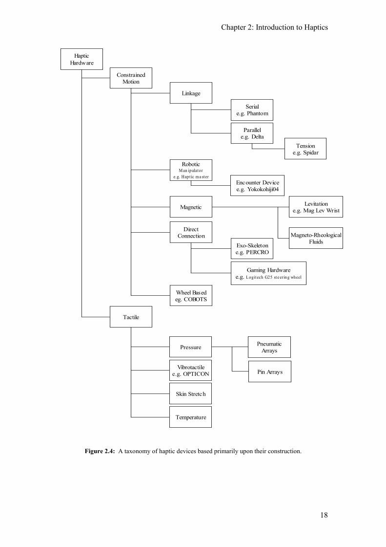
Figure 2.4: A taxonomy of haptic devices based primarily upon their construction.

Chapter 2: Introduction to Haptics
19
2.5.1 Terminology and Definitions Used to Describe Haptic
Interfaces
There are a number of terms and properties that are used to describe the various
important mechanical aspects of a haptic device. These terms and their meanings are
given here.
2.5.1.1 Degrees of Freedom (DOF)
The number of Degrees of Freedom of a haptic device (also referred to as the DOF of
the device) describes how many axes the device can be moved and controlled in.
Typically a device with 3 DOF will allow translational movement in 3 dimensions
whereas a 6 DOF device will also include rotation about the 3 axis. However, this is
not necessarily the case as some robotic manipulators and exoskeleton devices may
have a much higher DOF e.g. an exoskeleton glove may have 5 DOF, one for each
finger.
2.5.1.2 Grounded vs Un-Grounded
When a device is said to be grounded it allows the user to perceive weight. This
usually requires that the device is attached to the ground or to an immoveable object.
Because of this, the reactionary force created when a force is applied to the user is
transferred via the attached object to the ground and this allows forces to be provided
in any direction. This enables the display of the dynamic properties of an object, e.g.
mass and inertia as well as being able to physically impede the user when interacting
with fixed virtual objects, e.g. a virtual wall. Robotic manipulators and any desk
based devices are all said to be grounded devices.
An ungrounded device is usually attached to the body and is not capable of simulating
many aspects of a virtual environment. Dependant upon design, it is normally not
possible to simulate mass or inertia, and fixed virtual objects cannot normally impede
the user. However, ungrounded devices are able to be used to determine the shape of
objects and they do have a distinct number of advantages over grounded devices.
Since they are not restricted to being attached to the ground, ungrounded devices can
be used over a much larger area with no loss of fidelity and they are usually designed

Chapter 2: Introduction to Haptics
20
to be multi-finger capable. All wearable exoskeleton type haptic devices are
inherently ungrounded e.g. the Immersion Cyber Grasp [wwwCGrasp05].
2.5.1.3 Backdriveable vs Non-Backdriveable
For a haptic device to be backdriveable it means that when there is no power supplied
to the device, it can still be moved freely without impeding the user. Many of the
cable based haptic devices are backdriveable whereas the larger robotic manipulators
are non-backdriveable. Backdriveablilty is important as it determines which kind of
control strategy is required to use the device (see Section 2.5.3 for a description of the
different control strategies). Even though a system may be backdriveable the user
will still feel the inherent inertia of the device. This is described as the transparency
of the device.
2.5.1.4 Workspace
The workspace is the three dimensional area in which the device can move and
provide forces. This is primarily a characteristic of a grounded device.
2.5.1.5 Peak Force / Torque and Continuous Force / Torque
The peak force / torque is the maximum force / torque that the device can provide
whilst the continuous force / torque is the maximum sustainable force / torque that can
be applied. In systems where the overall movement is at a relatively slow speed, e.g.
less than 0.5ms-1, and a large proportion of the time is spent interacting with the
virtual objects then the continuous force should be maximised. However, in high
speed systems such as a golf or cricket simulator or a virtual drum kit peak force will
be more important.
2.5.1.6 Sensor Resolution
Sensor resolution describes the smallest change that can be detected by the sensor.
This is important as it is related to the positional resolution of the device at its
endpoint. The end point resolution is also important for the control system as it is
related to the maximum gain (and hence force) that can be generated at the endpoint.

Chapter 2: Introduction to Haptics
21
2.5.1.7 Impedance
Impedance is the resistive force of the device. A device can be described as having
low inherent impedance meaning that the force required to move the device is small.
Backdriveablilty and impedance are closely related as it is the inherent impedance of
the device that determines its backdriveablilty.
2.5.1.8 Bandwidth
The mechanical bandwidth of a device is the frequency that the force can be updated
as felt by the user. This is not to be confused with the update frequency of the control
algorithms.
2.5.2 Constrained Motion Haptic Devices
Constrained motion devices appeal to the kinaesthetic sense in order to portray
geometric information. Through the use of a stylus, finger thimble or handle, the user
is able to interact with a simulated environment. Upon contact with a virtual object
the device constrains the user such that the illusion of contact is conveyed.
2.5.2.1 Cable Linkage Mechanisms
(a) (b)
Figure 2.5: Two haptic devices that employ cable linkage mechanisms. a) the PHANToM from
Sensable Technologies [wwwSensable05], employs metal cables to transmit the forces whereas b) the
Freedom 6S, from MPD Technologies [wwwFreedom05], utilises Kevlar reinforced nylon threads.
Chapter 2: Introduction to Haptics
22
Cable linkage mechanisms are lighter and less susceptible to friction and backlash
then traditional linkage mechanisms used in robot manipulator technology and are
fully backdriveable. The kinematics of this type of device are well understood and
devices can be built with a large workspace although, due to the mechanical
properties of the linkages, bandwidth is limited. The Phantom [Massie96] [Cohen99]
is a robot arm style device where the user interacts via a stylus or thimble that
employs a cable driven mechanism. The Phantom is available in various
configurations with different workspaces and comes in 3 and 6 degrees of freedom
(DOF) versions. It is possible to use either a stylus or finger thimble on many of the
different models.
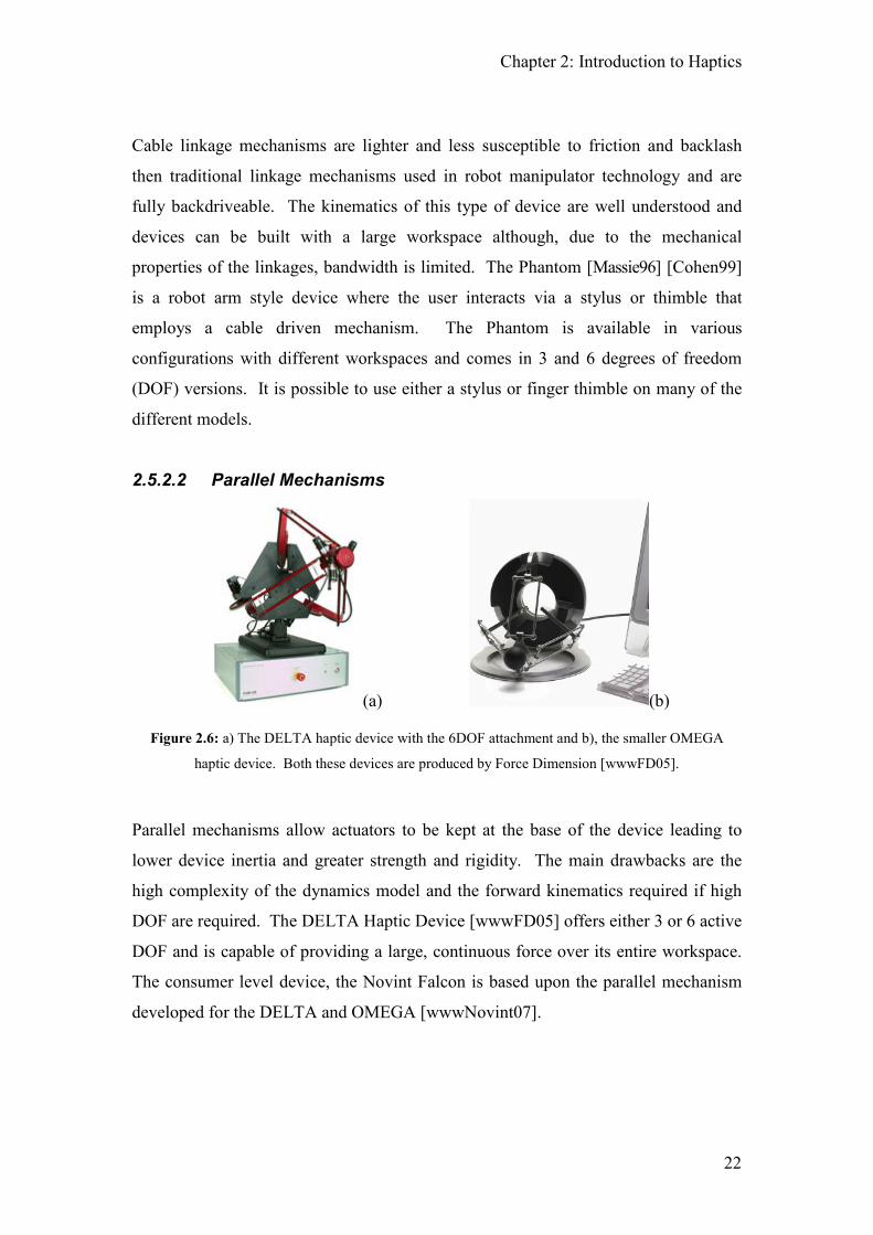
2.5.2.2 Parallel Mechanisms
(a) (b)
Figure 2.6: a) The DELTA haptic device with the 6DOF attachment and b), the smaller OMEGA
haptic device. Both these devices are produced by Force Dimension [wwwFD05].
Parallel mechanisms allow actuators to be kept at the base of the device leading to
lower device inertia and greater strength and rigidity. The main drawbacks are the
high complexity of the dynamics model and the forward kinematics required if high
DOF are required. The DELTA Haptic Device [wwwFD05] offers either 3 or 6 active
DOF and is capable of providing a large, continuous force over its entire workspace.
The consumer level device, the Novint Falcon is based upon the parallel mechanism
developed for the DELTA and OMEGA [wwwNovint07].

Chapter 2: Introduction to Haptics
23
Figure 2.7: The NOVINT Falcon, the first consumer targeted 3DOF haptic device [wwwNovint07].
2.5.2.3 Tensed String Devices
Figure 2.8: The SPIDAR 8 developed at the Tokyo Institute of Technology [wwwSPIDAR05].
Tensed string devices use thin cables or strings to transmit forces generated by remote
actuators directly to the user. They are capable of providing a large workspace and
have low weight and small inertia but require a large number of strings to simulate a
three dimensional force. The SPIDAR (Space Interface Device for Artificial Reality)
[Ishii94] interface is an example of a tensed string device with the SPIDAR 8
[Walairacht01] being capable of exerting forces on 8 fingers simultaneously. A major
disadvantage of the SPIDAR 8 is the limitation of direction that a force can be
applied, which is caused by the configuration of the strings. However, this is a
limitation of the SPIDAR 8 and not of the other SPIDAR devices. The representation

Chapter 2: Introduction to Haptics
24
of hard contact can also be poor in many tensed string devices although they do have
the distinct advantage of being usable in large VR systems (such as a CAVE) without
obscuring the projected images. The SPIDAR G (G for Grip) replaces the finger
gimbals with a spherical grip that the user is able to manipulate with 6 DOF [Kim03].
Figure 2.9: Two SPIDAR Gs setup for use in a bi manual configuration. This configuration is referred
to as the SPIDAR G & G [Murayama04].
2.5.2.4 Robotic Manipulators
Figure 2.10: The Haptic Master produced by FCS [wwwFCS05]. Because of its size a force sensor is
embedded at the endpoint that controls the direction of movement whilst in freespace.
Robotic manipulator arms, based on joint position servo loops, are large workspace
devices that usually have 3-6 degrees of freedom (DOF) in different configurations.
Due to their size and construction they normally use admittance control allowing for
the illusion of great rigidity in virtual objects whilst having difficulty in portraying
virtual free space. Examples of robot manipulators include the Haptic Master
[VanderLinde02], a robotic manipulator designed from the ground upwards for use as a
Chapter 2: Introduction to Haptics
25
haptic device, the MEL Master Arm [Kotoku92] and the JPL universal master
[Bejczy80], both developed for use in teleoperation applications with 4 DOF and 6
DOF respectively and the Magnetic Robot interface developed at the University of
Iowa [Luecke97], a robotic manipulator that couples the users hand to the robot
through magnetic actuation allowing both low and high frequency display in the same
device.
2.5.2.4.1 Encounter Devices
Encounter type devices are unique in that they are the only type of haptic device that
is not directly attached to the user but instead stays in a position and awaits the user to
encounter it. This provides real free sensations (as the user is in fact not touching
anything) as well as real touch sensations to the user. The motion of the hand is
recorded through the use of cameras and this motion is used to determine where a
collision will occur. The encounter device (normally in the form of a robot
manipulator arm) then moves into the desired position so that when a virtual collision
occurs, the robot is in the correct position to provide the haptic feedback. Work has
been done in the development of encountered-type haptic displays by McNeely, Tachi
and Yokokohji [McNeely93] [Tachi94] [Yokokohji04].
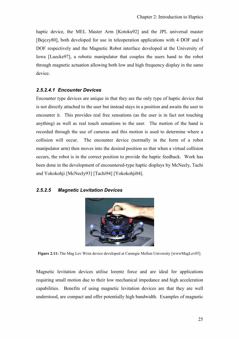
2.5.2.5 Magnetic Levitation Devices
Figure 2.11: The Mag Lev Wrist device developed at Carnegie Mellon University [wwwMagLev05].
Magnetic levitation devices utilise lorentz force and are ideal for applications
requiring small motion due to their low mechanical impedance and high acceleration
capabilities. Benefits of using magnetic levitation devices are that they are well
understood, are compact and offer potentially high bandwidth. Examples of magnetic
Chapter 2: Introduction to Haptics
26
levitation devices have been developed by Berkelman et al [Berkelman96]
[Berkelman97] [Berkelman99] and Salcudean and Parker [Salcudean97].
2.5.2.6 Magneto-Rheological Fluid Devices
A magneto-rheological fluid (MRF or MR fluid) is a liquid that solidifies when
exposed to an external magnetic field. They have been used to simulate object
compliances where the user physically touches the contained MRF [Scilingo00] as
well as in devices where the MRF is used as a damper [Noh09] [Han09].
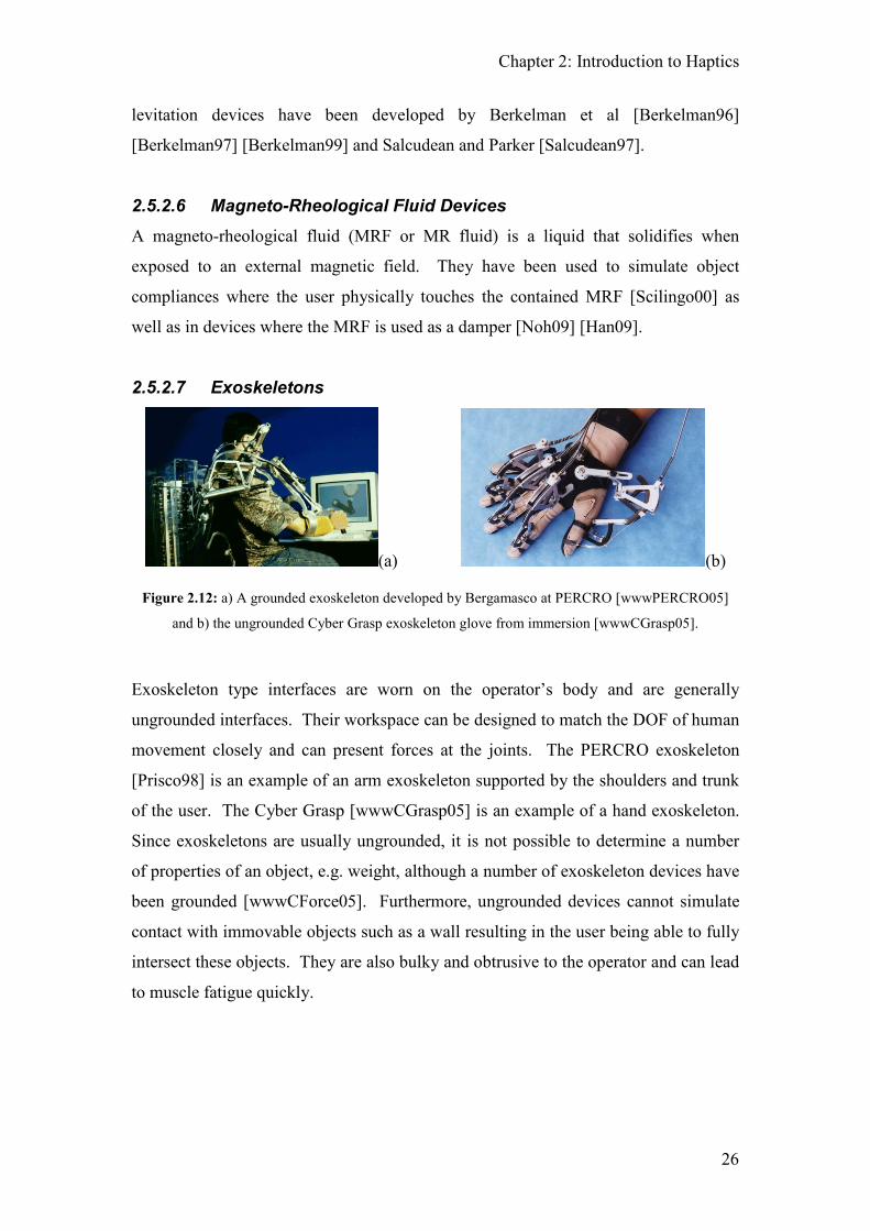
2.5.2.7 Exoskeletons
(a) (b)
Figure 2.12: a) A grounded exoskeleton developed by Bergamasco at PERCRO [wwwPERCRO05]
and b) the ungrounded Cyber Grasp exoskeleton glove from immersion [wwwCGrasp05].
Exoskeleton type interfaces are worn on the operator’s body and are generally
ungrounded interfaces. Their workspace can be designed to match the DOF of human
movement closely and can present forces at the joints. The PERCRO exoskeleton
[Prisco98] is an example of an arm exoskeleton supported by the shoulders and trunk
of the user. The Cyber Grasp [wwwCGrasp05] is an example of a hand exoskeleton.
Since exoskeletons are usually ungrounded, it is not possible to determine a number
of properties of an object, e.g. weight, although a number of exoskeleton devices have
been grounded [wwwCForce05]. Furthermore, ungrounded devices cannot simulate
contact with immovable objects such as a wall resulting in the user being able to fully
intersect these objects. They are also bulky and obtrusive to the operator and can lead
to muscle fatigue quickly.
Chapter 2: Introduction to Haptics
27
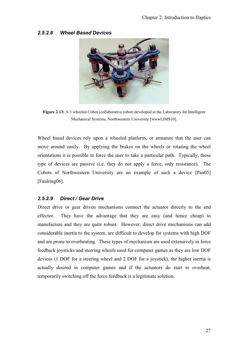
2.5.2.8 Wheel Based Devices
Figure 2.13: A 3 wheeled Cobot (collaborative robot) developed at the Laboratory for Intelligent
Mechanical Systems, Northwestern University [wwwLIMS10].
Wheel based devices rely upon a wheeled platform, or armature that the user can
move around easily. By applying the brakes on the wheels or rotating the wheel
orientations it is possible to force the user to take a particular path. Typically, these
type of devices are passive (i.e. they do not apply a force, only resistance). The
Cobots of Northwestern University are an example of such a device [Pan05]
[Faulring06].
2.5.2.9 Direct / Gear Drive
Direct drive or gear driven mechanisms connect the actuator directly to the end
effector. They have the advantage that they are easy (and hence cheap) to
manufacture and they are quite robust. However, direct drive mechanisms can add
considerable inertia to the system, are difficult to develop for systems with high DOF
and are prone to overheating. These types of mechanism are used extensively in force
feedback joysticks and steering wheels used for computer games as they are low DOF
devices (1 DOF for a steering wheel and 2 DOF for a joystick), the higher inertia is
actually desired in computer games and if the actuators do start to overheat,
temporarily switching off the force feedback is a legitimate solution.

Chapter 2: Introduction to Haptics
28
(a) (b)
Figure 2.14: a) The Logitech G25 force feedback steering wheel uses two motors to provide the force
feedback. This enables the G25 to provide the strongest force feedback possible without the problems
of overheating. b) The Logitech Forcetm 3D Pro force feedback joystick [wwwLogitechGames07].
2.5.3 Control Strategies for Constrained Motion Devices
Due to the mechanical construction of haptic devices, two main control strategies
have been developed in order to control them. Small, lightweight devices (or low
inherent inertia devices) such as the Phantom use impedance control (where the
position is controlled) whereas high inherent inertia devices, such as the Haptic
Master, use admittance control (where the force is controlled). In impedance control,
the user supplies a position to the controller which is used to generate a force whereas
with admittance control the user supplies a force to the controller in order to move to
a new position. With impedance control, the actuators are powered when the user is
in contact with a virtual constraint whereas with admittance control the actuators need
to be powered in order to move through virtual free space. As such, low inherent
inertia devices using impedance control are very good at simulating moving through
virtual free space but are unable to render very hard contacts. In contrast, high
inherent inertia devices using admittance control can create a very good illusion of
solidity when in virtual constraint but are unable to create inertia free movement
whilst moving in virtual free space.

Chapter 2: Introduction to Haptics
29
Table 2.3 shows the different properties of a number of constrained motion devices.
Device Workspace Peak Force /
Torque
Sensor
Resolution
Bandwidth
Position/Force
C.M. Maglev
Device
25x25x25mm
15-20o rotation
50N / 6 Nm 5-10 µm > 100Hz / ua
Phantom 1.5 195x270x375mm 8.5N / NA 0.03mm ua / 800 Hz
SPIDAR 300mm Diameter Sphere 4N / NA 0.503mm ua / 30 Hz
DELTA Haptic
Device
Cylinder: 360mm diameter x
300mm Length
25N / NA <0.1mm ua / ua
Table 2.3: Properties of different constrained motion devices. Key: NA means Not Applicable and ua
means that data is unavailable. The workspace is the area in which the haptic device is able to be used
freely before the mechanical structure starts to interfere, the Peak Force/Torque is the maximum
force/torque that can be applied over a short interval, it is not the maximum continuous force. The
Bandwidth refers to the maximum bandwidth that can be achieved by the device which determines the
maximum frequency that the device can display.
2.5.4 Tactile Displays
Tactile displays appeal to the cutaneous sense in order to portray high frequency
texture information, temperature or pain. We perceive surface texture through the
vibrations generated by stroking a finger over the surface. Tactile sensing is also the
basis of complex perceptual tasks like medical palpation, where physicians locate
hidden anatomical structures and evaluate tissue properties using their hands.
Tactile display devices stimulate the skin to generate these sensations of contact. The
skin responds to several distributed physical quantities; the most important are high-
frequency vibrations, small scale shape or pressure distribution and thermal
properties.
Chapter 2: Introduction to Haptics
30
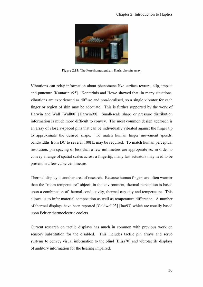
Figure 2.15: The Forschungszentrum Karlsruhe pin array.
Vibrations can relay information about phenomena like surface texture, slip, impact
and puncture [Kontarinis95]. Kontarinis and Howe showed that, in many situations,
vibrations are experienced as diffuse and non-localised, so a single vibrator for each
finger or region of skin may be adequate. This is further supported by the work of
Harwin and Wall [Wall00] [Harwin99]. Small-scale shape or pressure distribution
information is much more difficult to convey. The most common design approach is
an array of closely-spaced pins that can be individually vibrated against the finger tip
to approximate the desired shape. To match human finger movement speeds,
bandwidths from DC to several 100Hz may be required. To match human perceptual
resolution, pin spacing of less than a few millimetres are appropriate so, in order to
convey a range of spatial scales across a fingertip, many fast actuators may need to be
present in a few cubic centimetres.
Thermal display is another area of research. Because human fingers are often warmer
than the “room temperature” objects in the environment, thermal perception is based
upon a combination of thermal conductivity, thermal capacity and temperature. This
allows us to infer material composition as well as temperature difference. A number
of thermal displays have been reported [Caldwell93] [Ino93] which are usually based
upon Peltier thermoelectric coolers.
Current research on tactile displays has much in common with previous work on
sensory substitution for the disabled. This includes tactile pin arrays and servo
systems to convey visual information to the blind [Bliss70] and vibrotactile displays
of auditory information for the hearing impaired.

Chapter 2: Introduction to Haptics
31
2.5.5 Perceptual Effects Caused by Haptic Devices
When interacting in a virtual world using a haptic device a reasonably good
approximation of the world can be achieved using current technology. However a
number of factors relating to the haptic device can arise that can greatly affect the
user’s perceptions and thus destroy the illusion of touch. One of the most important
factors in rendering ‘believable’ haptic environments, with regard to impedance based
kinaesthetic type devices, is the need for a constant and high update rate for the
control loop; the de facto standard refresh rate is 1000Hz. These high update rates are
required as the update frequency is directly related to the maximum, stable stiffness
that can be achieved although the use of a lower update rate can still produce
acceptable results. Unfortunately, at high stiffness levels vibrations are more likely to
occur which destroys the illusion of touching a hard contact. For example, it has been
suggested that haptic update rates > 6000Hz are required in order to simulate very
stiff surfaces (>2000N/m) without perceivable vibrations occurring [Kabelak00].
Actuator saturation is also a concern since if the user provides more force than the
device can apply then the user will move through the object. Similarly, the system
dynamics of the device can have equally undesired effects such as the feeling of
moving through treacle (due to the device’s inherent inertia) when in virtual free
space.
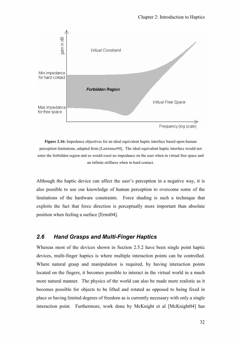
Figure 2.16 illustrates the impedance criteria that must be satisfied in order to achieve
ideal performance. If a constrained motion device lies outside the shaded region for
both virtual constraint and virtual free space it will be perceived as having no
resistance in virtual free space and infinite resistance when in virtual constraint
[Lawrence94]. The encounter type haptic devices are the only haptic devices that can
achieve this. However, the speed at which the robot arm can move to intercept the
user can add a large latency into the haptic simulation.
Chapter 2: Introduction to Haptics
32
Figure 2.16: Impedance objectives for an ideal equivalent haptic interface based upon human
perception limitations, adapted from [Lawrence94]. The ideal equivalent haptic interface would not
enter the forbidden region and so would exert no impedance on the user when in virtual free space and
an infinite stiffness when in hard contact.
Although the haptic device can affect the user’s perception in a negative way, it is
also possible to use our knowledge of human perception to overcome some of the
limitations of the hardware constraints. Force shading is such a technique that
exploits the fact that force direction is perceptually more important than absolute
position when feeling a surface [Ernst04].
2.6 Hand Grasps and Multi-Finger Haptics
Whereas most of the devices shown in Section 2.5.2 have been single point haptic
devices, multi-finger haptics is where multiple interaction points can be controlled.
Where natural grasp and manipulation is required, by having interaction points
located on the fingers, it becomes possible to interact in the virtual world in a much
more natural manner. The physics of the world can also be made more realistic as it
becomes possible for objects to be lifted and rotated as opposed to being fixed in
place or having limited degrees of freedom as is currently necessary with only a single
interaction point. Furthermore, work done by McKnight et al [McKnight04] has

Chapter 2: Introduction to Haptics
33
shown that a user’s effectiveness in interacting within a virtual environment is greatly
improved in terms of time taken and accuracy when using multiple interaction points.
Figure 2.17 shows a sphere being manipulated with multiple points of contacts.
Figure 2.17: A sphere being manipulated with three virtual fingers. The user is able to pick up and
rotate the sphere before placing it back down. With only one point of contact the orientation of the
sphere must be fixed otherwise it will be impossible to pick up the sphere.
2.6.1 Types of Hand Grasp
The way that we manipulate objects can be characterised by a number of different
hand movements. These movements were originally characterised into two distinct
groups by Napier [Napier56] as, non-prehensile movement “in which no grasping or
seizing is involved but by which objects can be manipulated by pushing or lifting
motions of the hand as a whole or of the digits individually” and prehensile movement
“in which an object is seized and held wholly within the compass of the hand.”
Napier also differentiates between power and precision grip. Landsmeer
[Landsmeer62] expanded upon this work by clarifying power grip and precision
handling, a term which he coins in preference to Napier’s precision grip since

Chapter 2: Introduction to Haptics
34
handling implies an active state in which manipulation is occurring. Using
Landsmeer’s definitions, a power grip is a “prehensile activity with no manipulation
taking place”. Another defining characteristic of the prehensile power grips is that the
whole hand wraps around the grasped object and invariably the object touches the
palm of the hand.
Figure 2.18: A grip taxonomy from [Cutkosky89]. On the left are the power grasps and on the right,
the precision grasps.
Whereas the power grips are appropriate for actions where large forces are required,
the precision grips are used when more precise actions are needed. The object is
grasped with the tips of the fingers allowing for precise movements of the object.
This includes actions such as writing with a pen or picking up small, lightweight,
objects.
Our choice of grip is determined by the task that we are undertaking and so it is not
appropriate to characterise the grip types based upon items held. For example, a
different grip is used if we are using a knife for chopping or slicing.

Chapter 2: Introduction to Haptics
35
2.6.2 Multi-Finger Haptic Systems
By choosing the placement of the interaction points it is possible to allow all of the
grasps described previously to be achieved (see Figure 2.19).
Figure 2.19: Three Phantom haptic devices mounted so that three fingers can be used to interact with
the virtual world. By replacing the rightmost Phantom with a palm attachment, power grips can also be
modelled. Unlike the immersion Cyber Grasp, this setup is fully grounded and so allows for the
simulation of weight as well as shape.
The advantage of using multi-finger devices over single point devices is the ability to
grasp and manipulate objects in a natural manner. When incorporated into a virtual
world, this can considerably reduce the learning time required in order to interact with
the world since the same real world actions can be directly applied in the virtual
world. This fast learning curve also allows users to do relatively complex tasks in
very short periods of time. For example, people who have never experienced
computer simulated haptics are quite capable of throwing a virtual ball into a virtual
hoop within 2 minutes of using the system without being given any instruction.
However, multi-finger systems currently suffer from two major problems: a smaller,
more restrictive workspace compared with an equivalent single finger device when
multiple devices are used, and bulky and obtrusive hardware for glove based devices.

Chapter 2: Introduction to Haptics
36
When combining a number of single finger haptic devices, as shown in Figure 2.19,
the workspace is reduced significantly in at least one of the dimensions. Movement is
also restricted due to the mechanical design of the devices which limits the range of
available degrees of freedom. For example, the system shown in Figure 2.19 has had
the workspace optimised for use with the right hand and sideways and vertical
motion. However, its workspace in the forward axis is limited to about 20cm
(compared to 37.5cm for a single finger device) and the hand can only be rotated
about 100 degrees around the wrist before the self collision occurs between the
mechanisms.
2.7 Applications
There are currently three main areas where haptic interfaces are used or being
developed. Medical / surgical simulation for training surgeons is an area of great
interest with a number of haptic devices developed specifically to resemble surgical
tools [wwwLapara05] [Chial02]. Research is also underway in the use of more
generic haptic devices (e.g. the Phantom) in order to facilitate the learning of cutting
through different materials with different types of instruments [Mahvash02]. The
development of these haptic devices has also led to the development of methods that
allow objects to be deformed [Corso02] and dissected [Kundu07] leading to research
in the area of volumetric modelling and how volumetric models interact with each
other when forces are applied [Kuroda02]. Haptic devices are also used in
rehabilitation and for assisting people with disabilities. The Optacon [Bliss70] was
developed in order for the visually impaired and blind to read standard text.
Consisting of a photosensitive detector and a pin based tactile display, the user scans
the text which is then converted into Braille and displayed on the tactile pin array
which they are then able to sense. Haptic systems are also being developed in order to
assist in the rehabilitation of stroke patients [Amirabdollahian02]. Utilising the large
workspace of the Haptic Master, the haptic device guides and corrects the users
position whilst they are exercising in much the same way that a physiotherapist
would.
Teleoperation is another area where the addition of haptic stimulation is beneficial. If
the operator is able to ‘feel’ what the robot ‘feels’, then this gives the operator a better

Chapter 2: Introduction to Haptics
37
understanding of the environment and task that the robot is undertaking. In fact, the
development of haptics emerged from the field of teleoperation; haptic feedback
devices were pioneered in teleoperation systems as far back as the 1940s. In both
teleoperation and virtual environments where haptics are used, a loop is closed
between the human operator ‘inputs’ and forces applied by the haptic device. In
teleoperation this loop is closed via a communication link, robotic manipulator and
the environment. In virtual environments, the loop is closed via a simulation.
Figure 2.20: An 8 player version of Virtua Racing by SEGA, 1992. Each race car would move around
and force feedback was also provided through the steering wheel [wwwVRRacer07].
Perhaps the most widespread use of haptic devices is in the entertainment industry.
The first haptic enabled systems were racing arcade machines where the player would
sit in a replica car and the car body would move in a manner determined by what the
player did with further feedback being received through the steering wheel.
Motorbike arcade machines (such as SEGA’s Hang-on [wwwHangOn07]) also
existed where the player would sit on a replica motorbike and would feel the bike
move. The player would also need to use his body to turn corners by throwing his
body into the turn. With the increase in computer and game console ownership there
are now a number of cheap haptic enabled input devices available including force
feedback joysticks and steering wheels [wwwLogitech07], vibro-tactile joypads, and
both force feedback and vibro-tactile mice [wwwiFeel05] [wwwWingman05]. Game
development studios are also incorporating haptic feedback into more games that
make use of these ‘force enabled’ devices. The Nintendo Wii in particular is a
console that was designed from the outset to incorporate a novel input device that was

Chapter 2: Introduction to Haptics
38
both motion sensitive as well as providing haptic feedback in the form of both a
“rumble” actuator and a speaker embedded in the handset [wwwWiiMote10].
Other areas where haptics have been used include scientific visualisation,
collaboration in virtual environments and industrial modelling.
One of the most prominent examples of the use of haptics in scientific visualisation is
Project GROPE [Brooks90]. This used a high DOF haptic device in order to augment
a visual display to improve the perception and understanding of both force-fields and
of world models populated by impenetrable objects. The aim of the project was to
assist a chemist in finding solutions to molecular docking problems using haptics as a
means to feel the intermolecular forces. They found that, after some initial training,
chemists were quickly able to find known solutions for drug docking whilst very good
docks were found for drugs whose true docking was still unknown.
Research is also underway investigating how haptics can be integrated into
collaborative virtual environments (CVEs) to facilitate the collaborative aspects of
tasks involving more than one person. Preliminary results have shown that the
addition of haptics allows much quicker solutions to be found [Seelig03]. Suitable
network protocols are also being developed in order to facilitate the high data
bandwidth that haptics requires so that remote users can interact haptically with the
same virtual object [Jordan02].
Stylus based haptic devices are starting to appear in industrial modelling. Instead of
using the more usual mouse based approach to building 3D models, a haptic device
(such as the Phantom) can be used in the same way that a sculptor models in clay. By
starting with a block of virtual clay the stylus can then be used to deform the clay to
generate the final model. Similarly, haptic devices are finding applications where
models and materials can be touched and explored without the need to build an
expensive prototype or in situations where it is possible to only feel a virtual product
[Moody01].

Chapter 2: Introduction to Haptics
39
2.8 Current Limitations of Haptic Devices
Current generic haptic devices posses a number of limitations that reduces their ability
to be used in a totally natural manner. The majority of haptic devices are single point
devices that are interacted with through the use of a stylus or finger gimbal. In the
real world, as we explore an object we normally use more than one finger if not our
whole hand in the exploration process [Lederman93]. Interaction with an object
through the stylus takes advantage of distal attribution, the ability for humans to easily
extend their perception to the end of an implement, yet in reality the majority of
exploration that we do is finger based. Also, the end point, or haptic interaction point,
is just that – a point. When humans explore a surface they know when they are
approaching an edge and are easily able to traverse the edge without falling off the
object. This is due to the shape of our finger pads which allows partial contact with
the surface and our knowledge that if we don’t change the direction of the force that
we apply we will fall off the edge. With a point contact we have no ability to
haptically determine whether we are approaching an edge which causes us to fall off
edges easily. Work in the area of haptic rendering [Morgenbesser95] and hardware
design [Kuchenbecker04] has been done in order to try and alleviate this problem but
both solutions are compromises and not an ideal solution. Another approach that
gives a more lifelike feel to edges involves replacing the haptic interaction point with
a volume such as a cylinder or a sphere. Again, this is not the perfect solution but it
does allow the user to experience the change in the direction of the simulated force as
an edge is traversed.
When using a single point device we are also limited to the kind of actions that we can
perform. Picking up objects can only be achieved if we have a ‘handle’ that we can
reach under and lift or by not simulating rotations due to contact.
Humans also explore the world through the use of more than one finger. When we try
to identify an object by its shape we use many fingers to help us build up an image of
the object. Although this is possible with a single finger input device it takes longer
to accomplish than in the real world with a lower probability of successful
identification. Multi-finger haptic devices exist [wwwCGrasp05] but these are
usually ungrounded and so it is possible to interpenetrate the objects and the illusion
Chapter 2: Introduction to Haptics
40
of weight cannot be conveyed. Although grounded multi-finger devices are also
available [wwwCForce05] the bulk and obtrusiveness of such devices can have an
adverse effect on the illusion.
All grounded haptic devices have a limited workspace. Increasing the size of the
workspace potentially has the effect of introducing compliance into the system which
reduces the ability to simulate a hard contact. Although some haptic devices are
capable of a large workspace, e.g. the SPIDAR, the compliance in the system and
reduction in maximum exertable force can help to destroy the illusion of contact.
Large workspace devices need to be engineered from the start as large workspace
devices (as was done when the Haptic Master [VanderLinde02] was developed) instead
of just increasing the size of existing devices, as can be seen by the performance of
the Phantom 1.5 compared with the Phantom 3.0.
As noted earlier, haptic devices generally stimulate either the cutaneous or
kinaesthetic sense. It has been shown that by integrating both kinaesthetic and
cutaneous stimulation into a single device a more realistic experience can be provided
[Wall00]. Kuchenbecker et al [Kuchenbecker04] have demonstrated a simple
attachment to the Phantom allowing both cutaneous and kinaesthetic feedback to be
applied in order to aid in edge transitions. The limited bandwidth of constrained
motion devices and the non-kinaesthetic stimulation of tactile displays are limitations
to both types of display. However, there are many applications where these
limitations are inconsequential, e.g. using a tactile display to feel the texture of cloth
[Moody01].
2.9 Haptic Software Components
There are a number of software components that are required in order to create a
haptic enabled system. Figure 2.21 shows the typical systems that are required and
how they are typically linked.
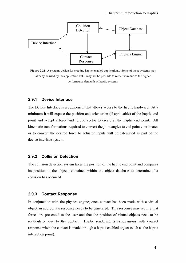
Chapter 2: Introduction to Haptics
41
Figure 2.21: A systems design for creating haptic enabled applications. Some of these systems may
already be used by the application but it may not be possible to reuse them due to the higher
performance demands of haptic systems.
2.9.1 Device Interface
The Device Interface is a component that allows access to the haptic hardware. At a
minimum it will expose the position and orientation (if applicable) of the haptic end
point and accept a force and torque vector to create at the haptic end point. All
kinematic transformations required to convert the joint angles to end point coordinates
or to convert the desired force to actuator inputs will be calculated as part of the
device interface system.
2.9.2 Collision Detection
The collision detection system takes the position of the haptic end point and compares
its position to the objects contained within the object database to determine if a
collision has occurred.
2.9.3 Contact Response
In conjunction with the physics engine, once contact has been made with a virtual
object an appropriate response needs to be generated. This response may require that
forces are presented to the user and that the position of virtual objects need to be
recalculated due to the contact. Haptic rendering is synonymous with contact
response when the contact is made through a haptic enabled object (such as the haptic
interaction point).
Device Interface
Collision
Detection Object Database
Contact
Response
Physics Engine
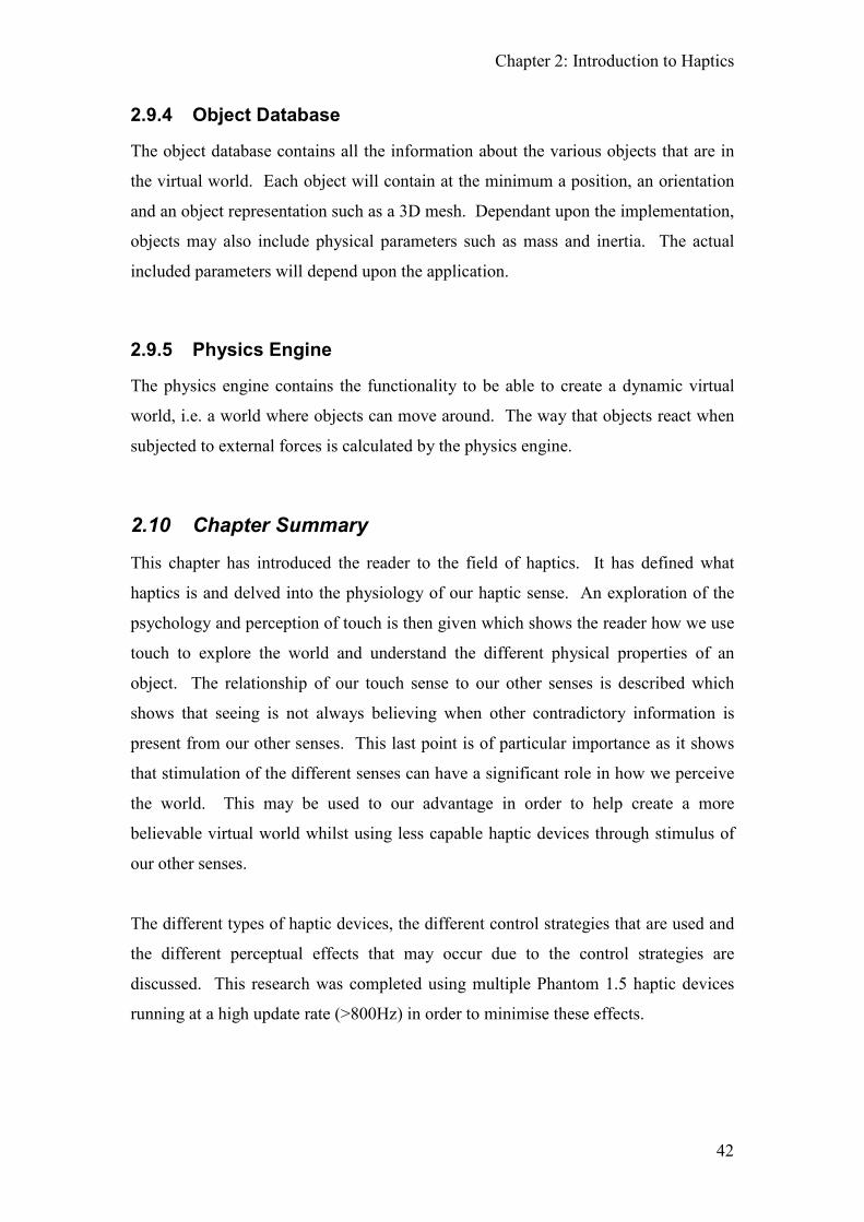
Chapter 2: Introduction to Haptics
42
2.9.4 Object Database
The object database contains all the information about the various objects that are in
the virtual world. Each object will contain at the minimum a position, an orientation
and an object representation such as a 3D mesh. Dependant upon the implementation,
objects may also include physical parameters such as mass and inertia. The actual
included parameters will depend upon the application.
2.9.5 Physics Engine
The physics engine contains the functionality to be able to create a dynamic virtual
world, i.e. a world where objects can move around. The way that objects react when
subjected to external forces is calculated by the physics engine.
2.10 Chapter Summary
This chapter has introduced the reader to the field of haptics. It has defined what
haptics is and delved into the physiology of our haptic sense. An exploration of the
psychology and perception of touch is then given which shows the reader how we use
touch to explore the world and understand the different physical properties of an
object. The relationship of our touch sense to our other senses is described which
shows that seeing is not always believing when other contradictory information is
present from our other senses. This last point is of particular importance as it shows
that stimulation of the different senses can have a significant role in how we perceive
the world. This may be used to our advantage in order to help create a more
believable virtual world whilst using less capable haptic devices through stimulus of
our other senses.
The different types of haptic devices, the different control strategies that are used and
the different perceptual effects that may occur due to the control strategies are
discussed. This research was completed using multiple Phantom 1.5 haptic devices
running at a high update rate (>800Hz) in order to minimise these effects.

Chapter 2: Introduction to Haptics
43
Since this thesis is concerned with multi-finger manipulation, an exploration of the
different types of hand grasp are given and how multi-finger haptic systems can be
designed to allow for the different grasps.
The three main areas where haptics is used is discussed. This includes medical /
surgical simulation, teleoperation and entertainment. Other areas are also touched
upon. This is not an exhaustive list of the areas where haptics is employed but gives a
rounded picture of what is currently available.
This chapter concludes with the current limitations of haptic devices, in particular the
limited manipulative abilities of a single point device and the simplification of physics
modelling on multi-point devices, and a brief guide to the requirements for developing
a haptic enabled software simulation.
As shown by this chapter, the area of haptics is a huge field to research in. As there
has been limited work done in the field of multi-finger haptics the rest of this thesis is
concerned with how natural manipulation of virtual objects can be achieved. Since it
is possible to create an effective (albeit with a limited workspace) three finger haptic
system using multiple Phantoms, the main concern of this thesis is the software
algorithms required to achieve natural manipulation of virtual objects. This area of
research is generally referred to as haptic rendering as it takes the data from the virtual
world and renders it into a suitable form for the user to experience (i.e. a force
provided to the haptic device). The following chapter delves deeper into haptic
rendering and physics modelling in order for the reader to understand the background
of the research.

44
3 Physical Modelling and Rendering Methods
Physically based simulation in haptic environments requires that manipulated objects
have attributes analogous to physical properties observed in the real world. These
include mass and inertia for direct object manipulation as well as properties such as
surface texture and frictional characteristics. A minimum set of requirements for the
successful implementation of a haptic enabled physical simulation requires:
1 The identification of collisions. This is a problem of collision detection,
which becomes more difficult and computationally expensive as the model of
the virtual environment becomes more complex.
2 An estimation of external forces resulting from the collisions (including
shear forces such as friction). This force is applied back through the haptic
device and creates the ‘feel’ of the object.
3 An appropriate response to the residual forces. This is the overall response
of the object based upon all the forces acting upon it.
Haptic rendering is concerned with finding solutions to 2 and 3 above.
The purpose of this chapter is to investigate the current methods of haptic rendering
currently used for feeling and manipulating solid, non-deformable objects. An
examination of the various friction models and implementations is given since surface
friction is both an important object property and essential for the natural manipulation
of an object. The physical properties that are required for an object to be manipulated
are also examined. Since it is necessary that contact is made between the object and
the haptic interaction point, collisions detection methods for haptic systems are also
described.
3.1 Current Haptic and Visual Rendering Methods
Rendering is the process of taking raw data stored in a computer and turning it into a
human understandable form. In graphics this involves converting the 3D model data
into a 2D image displayed on the monitor and in haptics, rendering is the process of

Chapter 3: Physical Modelling and Rendering Methods
45
determining what force (direction and magnitude) should be applied to the haptic
device in order for the user to feel it.
3.1.1 Visual vs Haptic Rendering
There are three significant differences between visual and haptic rendering: minimum
required update rate, scene complexity and dedicated hardware.
Haptic rendering must occur at a high update rate, preferably > 1000Hz, in order to
convey a realistic and believable sensation. In contrast to this, in order to convince
our visual system that an object is moving a persistent, graphical update rate > 24Hz
is required. Compared with the field of real time graphic rendering, haptic rendering
is a much newer field. As such haptics does not yet benefit from the vast array of
different rendering methods available to graphics or that many of these algorithms
have been implemented in hardware to greatly increase the speed of their execution.
Due to the greater maturity of graphic rendering, along with the advantages of
hardware acceleration, it is possible to graphically render extremely complex scenes
that are realistically lit in realtime. Although haptic rendering is conceptually a lot
simpler than graphical rendering, since only a few forces need to be generated
compared with rendering an entire scene, the high update rate required and the
potentially large quantity of data that needs to be processed each update makes this a
non-trivial problem.
3.1.2 Single Point Haptic Rendering Methods
Haptic rendering methods have been developed in order to simulate both rigid and
deformable surfaces. Force estimation is usually calculated from the ‘depth of
penetration’ once a collision has been detected.
3.1.2.1 Vector Field methods
Initially, haptic rendering was focused on the display of simple, rigid, and frictionless
3D objects such as a cube, cylinder, or sphere using vector field methods; the force to
apply is proportional to the depth of penetration and, for simple objects (spheres and
cylinders), the direction can be calculated based upon a mathematical description of

Chapter 3: Physical Modelling and Rendering Methods
46
the object (see Figure 3.1). For more complex objects, the computations for
determining the force vector sometimes involve dividing the object into sub-spaces
associated with particular portions of the object’s surface (see Figure 3.2). The
problem with this method of rendering occurs when the haptic interaction point (the
virtual representation of the actual haptic point) crosses between these subspaces as
the direction and magnitude of the force would change abruptly in a very non-real
world manner. Vector field methods also suffer from ‘push through’, the ability to
actually push through the object and come out of the other side.
HIP
R
Fdistance
Figure 3.1: Rendering a sphere using the vector field method. The direction of the required force is
always in the direction of the haptic interaction point (HIP) to the centre of the sphere. The magnitude
of the force is proportional to the depth of penetration.
F
F
Figure 3.2: Rendering a cube using the vector field method. The cube is divided into 6 equal volumes
to determine the direction of the force vector. As the haptic interaction point moves from one region to
the next a strong discontinuity occurs due to the sudden change in direction of the force.
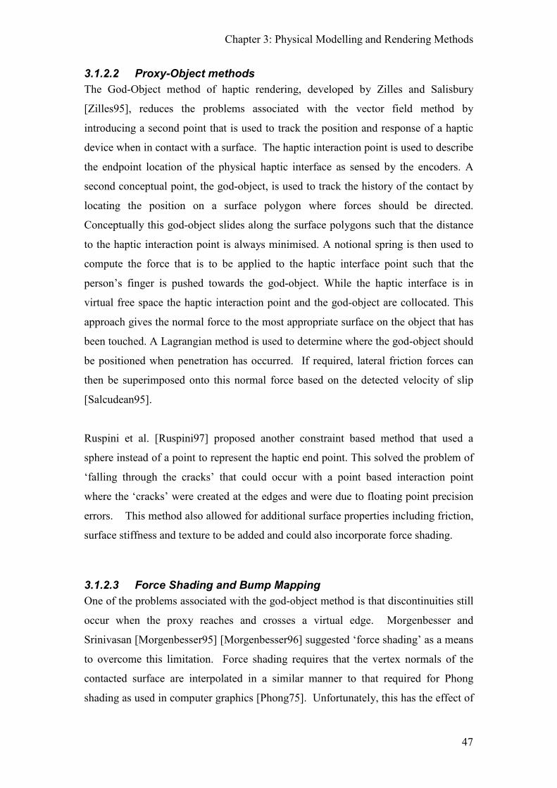
Chapter 3: Physical Modelling and Rendering Methods
47
3.1.2.2 Proxy-Object methods
The God-Object method of haptic rendering, developed by Zilles and Salisbury
[Zilles95], reduces the problems associated with the vector field method by
introducing a second point that is used to track the position and response of a haptic
device when in contact with a surface. The haptic interaction point is used to describe
the endpoint location of the physical haptic interface as sensed by the encoders. A
second conceptual point, the god-object, is used to track the history of the contact by
locating the position on a surface polygon where forces should be directed.
Conceptually this god-object slides along the surface polygons such that the distance
to the haptic interaction point is always minimised. A notional spring is then used to
compute the force that is to be applied to the haptic interface point such that the
person’s finger is pushed towards the god-object. While the haptic interface is in
virtual free space the haptic interaction point and the god-object are collocated. This
approach gives the normal force to the most appropriate surface on the object that has
been touched. A Lagrangian method is used to determine where the god-object should
be positioned when penetration has occurred. If required, lateral friction forces can
then be superimposed onto this normal force based on the detected velocity of slip
[Salcudean95].
Ruspini et al. [Ruspini97] proposed another constraint based method that used a
sphere instead of a point to represent the haptic end point. This solved the problem of
‘falling through the cracks’ that could occur with a point based interaction point
where the ‘cracks’ were created at the edges and were due to floating point precision
errors. This method also allowed for additional surface properties including friction,
surface stiffness and texture to be added and could also incorporate force shading.
3.1.2.3 Force Shading and Bump Mapping
One of the problems associated with the god-object method is that discontinuities still
occur when the proxy reaches and crosses a virtual edge. Morgenbesser and
Srinivasan [Morgenbesser95] [Morgenbesser96] suggested ‘force shading’ as a means
to overcome this limitation. Force shading requires that the vertex normals of the
contacted surface are interpolated in a similar manner to that required for Phong
shading as used in computer graphics [Phong75]. Unfortunately, this has the effect of
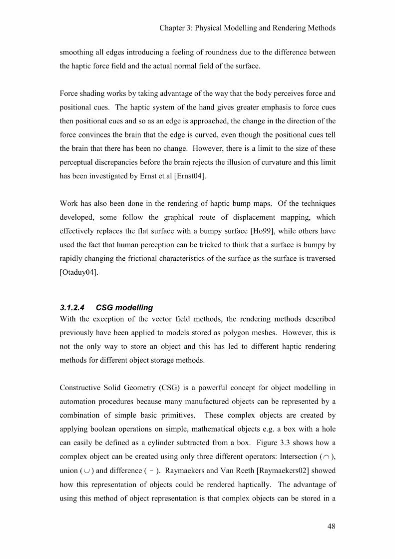
Chapter 3: Physical Modelling and Rendering Methods
48
smoothing all edges introducing a feeling of roundness due to the difference between
the haptic force field and the actual normal field of the surface.
Force shading works by taking advantage of the way that the body perceives force and
positional cues. The haptic system of the hand gives greater emphasis to force cues
then positional cues and so as an edge is approached, the change in the direction of the
force convinces the brain that the edge is curved, even though the positional cues tell
the brain that there has been no change. However, there is a limit to the size of these
perceptual discrepancies before the brain rejects the illusion of curvature and this limit
has been investigated by Ernst et al [Ernst04].
Work has also been done in the rendering of haptic bump maps. Of the techniques
developed, some follow the graphical route of displacement mapping, which
effectively replaces the flat surface with a bumpy surface [Ho99], while others have
used the fact that human perception can be tricked to think that a surface is bumpy by
rapidly changing the frictional characteristics of the surface as the surface is traversed
[Otaduy04].
3.1.2.4 CSG modelling
With the exception of the vector field methods, the rendering methods described
previously have been applied to models stored as polygon meshes. However, this is
not the only way to store an object and this has led to different haptic rendering
methods for different object storage methods.
Constructive Solid Geometry (CSG) is a powerful concept for object modelling in
automation procedures because many manufactured objects can be represented by a
combination of simple basic primitives. These complex objects are created by
applying boolean operations on simple, mathematical objects e.g. a box with a hole
can easily be defined as a cylinder subtracted from a box. Figure 3.3 shows how a
complex object can be created using only three different operators: Intersection (∩ ),
union (∪ ) and difference ( - ). Raymaekers and Van Reeth [Raymaekers02] showed
how this representation of objects could be rendered haptically. The advantage of
using this method of object representation is that complex objects can be stored in a

Chapter 3: Physical Modelling and Rendering Methods
49
small amount of memory and that curved surfaces can be haptically rendered
correctly.
Figure 3.3: By applying boolean operators with simple primitives, complex shapes can be easily
generated [wwwCSG].
3.1.2.5 NURBS modelling
NURBS (Non-Uniform Rational B-Splines) are another method whereby objects are
represented in graphics, particularly in computer aided design (CAD) packages.
NURBS are a parametric means of describing an object’s surface and are ideally
suited for the creation of ‘organic’ objects that feature many curved surfaces.
Methods have been proposed for the haptic rendering of NURBS surfaces
[Thompson99] [Patoglu05] but due to the highly mathematical nature of this type of
surface it is computationally expensive to use for haptic rendering. This is due to the
fact that there is no simple solution to finding where a ray collides with the surface
which is necessary for calculating the depth of penetration and surface normal. The

Chapter 3: Physical Modelling and Rendering Methods
50
only way to calculate this point is to use an iterative method that will converge on the
desired point and so it also does not guarantee that the exact point of collision will be
returned [Wang05].
3.1.2.6 Deformable Meshes
All the haptic rendering methods described so far have been used to simulate rigid
surfaces. Since one of the principle applications of haptics is in surgical simulation
and training, a large amount of research has been in the development of deformable
haptic rendering techniques. Finite Element Methods are both comprehensive and
well suited for accurate computation of deformations but, due to the complexity of the
models required and the time required to invert the large but sparse matrices involved,
they are unable to run at haptic rates. Methods that have been successful include
modified Spring-Mass-Damper methods [Jansson02] [Maciel04], Long Element
Methods [Balaniuk00], Radial Element Methods [Balaniuk03] and methods based upon
the Medial Axis Transform [Corso02].
Tetrahedral meshes are another representation for solid objects ideally suited to
haptics. A tetrahedral mesh is the equivalent volumetric representation of a triangular
surface mesh and they both share many of the same properties. Any volume can be
represented using a tetrahedral mesh, and many of the techniques used with triangular
meshes, such as subdivision of surfaces, and surface smoothing, can be easily
modified for use with tetrahedrons. Tetrahedral meshes have been successfully used
for simulating bone drilling [Fellner06] and for simulating tissue cutting for open
surgery [Kundu07].
3.1.3 Multi-Point Haptic Rendering
The key advantage that multi-point haptic systems have over single point systems is
the ability to manipulate objects in a realistic manner. When manipulating an object
with a single finger it is only possible to move the object by pushing it. It is only
possible to lift an object if it has an overhang or a hook as part of its structure or by
constraining the rotational axis of the object so that it becomes possible to lift it from
the bottom. For more complex single point manipulations it becomes necessary to
Chapter 3: Physical Modelling and Rendering Methods
51
attach the virtual object to the haptic interface through the use of an external system,
such as a button. When using multiple interaction points, grasping and manipulating
objects in a natural and intuitive manner becomes possible.
Although multi-finger haptic devices exist there is very little literature on how
simulated objects react when under the influence of multiple points of contact. Boulic
et al [Boulic96] describe methods for manipulating objects with multiple fingers but
they were using non-force feedback gloves. They describe a method that shows a
correct visual representation of a hand on the object even though the user’s actual
hand may be in a more closed form. By storing two models of the hand, the virtual
hand being displayed and the actual hand given by the data glove sensors, forces on
the grasped object were able to be calculated based upon the penetration of the actual
hand model. This method allowed for objects to be ‘rolled’ on the fingers by the
thumb. When the object was defined as being grasped, the object was attached to the
hand coordinate frame and moved with the hand.
Maekawa and Hollerbach [Maekawa98] describe methods for two finger grasping and
manipulation of virtual objects via a haptic interface. However, what they described
is based upon six assumptions, the most important ones being listed here:
Assumption 3: When only one fingertip makes contact on the object, the
contact is frictionless;
Assumption 4: When an object is grasped by two fingers, each fingertip sticks
on the object surface without slip;
Assumption 5: Although the object is grasped only by two fingers, its rotation
around the axis that connects the two fingertips is constrained;
Assumption 6: While manipulating the object, its dynamics due to inertia is
omitted.
Since multi-finger devices allow us to grasp and manipulate objects in a more natural
manner, it is reasonable to expect any multi-finger simulation to allow for this. In the
real world, when we pick up an object we need to overcome gravity and we are able
to translate and rotate the object at will. This requires simulating friction in order to

Chapter 3: Physical Modelling and Rendering Methods
52
be able to lift the object as well as being able to resolve the forces and torques on the
grasped object to allow it to be manipulated.
3.2 Friction
Friction is an important aspect of haptic rendering as it contributes a reactive force to
virtually all mechanical systems and is a property of all real world objects. Friction is
also an essential component in object manipulation; in order to lift an object it is
necessary to grip hard enough in order to increase friction and hence overcome the
force due to gravity. If an object is not grasped with enough force then the object will
slip although excessive force can lead towards fatigue.
3.2.1 Friction Models and Friction Modelling
The ‘Classical’ model of friction, that relates the normal force to the opposing motion,
was postulated by Leonardo da Vinci and was rediscovered by Amontons in 1699 and
further developed by Coulomb in 1785. These rules are that ‘the friction is
independent of the geometrical area of contact’ and the ‘frictional force is
proportional to the normal force’. Subsequent work by Bowden and Tabor in 1950
[Bowden50] showed that the frictional force depended on the true area of contact as
measured by the adhesion of microscopic asperities on each contacting surface. Figure
3.4 shows some common models developed to describe frictional forces. Figure 3.4(a)
is the only linear model and is widely used for analysis even though it is the least
accurate.
Figure 3.4: Various friction models showing the retarding force (y-axis) versus the velocity (x-axis):
(a) viscous damping; (b) Coulomb model; (c) Coulomb and viscous; (d) “stiction”; (e) Karnopp’s
model; (f) Stribeck effect;
a) b) c) d) e) f)
Friction Friction Friction Friction Friction Friction
Velocity Velocity Velocity Velocity Velocity Velocity

Chapter 3: Physical Modelling and Rendering Methods
53
These models describe the force that opposes the relative velocity of the two surfaces.
In all but the linear friction of Figure 3.4 (a) care is needed to ensure that the friction
forces can only oppose the applied shear force, and that the transition from ‘stuck’ to
‘slip’ is handled sensibly. Among these more complex models is the Dahl model
[Dahl76] which models friction as a local stiffness during the ‘stuck’ state. Thus the
Dahl model behaves like Columb friction at large amplitudes, and ‘structural
damping’ at low amplitudes. “Stiction” or “stick-slip” is modelled by ensuring that
the static value of friction is higher than the dynamic value (Figure 3.4 (d)). The
Karnopp friction model [Karnopp85], proposed in 1985, was developed to simulate
stiction and was developed specifically for digital simulation where the combination
of high sample rates and sensor noise results in erroneous estimates of velocity at low
speeds. The Karnopp model achieved this using a small region surrounding the zero
velocity where the stick region is modelled as a force proportional to the velocity and
a constant Coulomb force is applied in the slip region. Haessig et al [Haessig91]
developed the ‘Bristle’ and the ‘Reset Integrator’ models in 1991, which although
accurate, have a heavy computational penalty. Perhaps the most comprehensive
friction model is the LeGre friction model [Lischinsky99] which is a development of
the Dahl model and includes an internal state to allow for microslip. One phenomena
modelled by the LeGre model is the Stribeck effect shown in Figure 3.4 (f). The
Stribeck effect governs the transition from ‘stuck’ to ‘slip’ where the value of the
friction force decreases as the velocity increases. For a survey of friction models, the
reader is referred to Armstrong-Helouvry et al. [Armstrong-Helouvry94].
In the field of modelling friction for haptic interfaces, Richards and Cutosky
[Richards02] discuss both the Dahl and computationally simpler Karnopp model, and
then use the latter to describe the friction characteristics of a number of materials
including aluminium-teflon, aluminium-brass and aluminium-rubber. They noted that
the trouble with haptic rendering of textures was the difficulty in getting an accurate
estimation of interface velocity at near zero velocities where quantisation noise from
the encoders is high. Hayward et al [Hayward00] have also proposed a friction model
for haptic interfaces based on the Dhal model adapted to account for numerical
implementation and to minimise drift due to the dominance of noise in the position
measurement at low speeds. These models do not however, extend readily to the

Chapter 3: Physical Modelling and Rendering Methods
54
implementation of stable friction based grasps as described by the authors in
[Melder03].
Little work has been done on how we perceive friction and which characteristics are
important for the haptic rendering of friction. This information is necessary as it
defines the design parameters required by the hardware manufacturers so that the
limitations of the haptic device can match human perception limits.
3.2.2 Friction Implementations
Linear viscous damping is the most commonly utilised model of friction (Figure 3.4
(a)) due to its simplicity and ease of implementation and it is often used to simulate
the friction between two objects. Simulating friction between the haptic interaction
point and an object normally uses a stick-slip friction model and is implemented in
two stages. Initially, a proxy based algorithm is used to calculate the desired normal
force. Frictional components are then calculated and overlaid on top of the previously
calculated force.
Salcudean [Salcudean95] and Provancher [wwwProvancher07] describe how a
slightly modified Karnopp model can be implemented. According to the Karnopp
model, a mass sliding on a surface with stick-slip friction can be in two states, stuck
or slip. When in the stuck state, any external forces (fext) acting on the mass will be
exactly balanced and the mass will remain in the stuck state. However, once the
external force magnitudes exceeds a set value (fmax) the mass state changes to the slip
state. While in the slip state, a damping force is exerted on the motion until the
velocity of the mass is less than a set value (vmin). At this point the mass changes back
to the stuck state.

Chapter 3: Physical Modelling and Rendering Methods
55
Figure 3.5: Stuck phase for Karnopp model. Since the current position is past the transition point, a
state change will occur on the next update.
From the equations of motion,
ext v stickmx f k x f= − +�� � [3.1]
While in the stuck state fstick is given by
( )stick stuckf k x x= − [3.2]
When fstick > fmax the state changes to slip. While in the slip state the fstick = 0.
When the velocity goes below a threshold velocity, the object returns to the stuck
phase. It is also common that whilst in the sliding phase, viscous frictional forces are
superimposed onto the haptic device. These viscous forces are calculated as acting
proportionally and in opposition to the velocity of motion.
3.3 Hand Grasps and Object Manipulation Physics
As described in Section 3.1.3 friction is an essential component in object
manipulation since, in order to lift an object, it is necessary to grip hard enough to
increase friction in order to overcome the force due to gravity. When holding an
object, a stable grasp is also required although it is not necessary to grasp an object in
order to manipulate it. Additionally, when simulating manipulation it is necessary to
determine how the object should react to all the forces being applied to it.
xstuck is the position where
forces are directed
x is the current position
T is the transition point where
a change to sliding will occur.
Direction of Motion
Force @ x = k * (xstuck-x)
xstuck T x

Chapter 3: Physical Modelling and Rendering Methods
56
3.3.1 Residual Force Resolution
When a hand holds an object at rest, the forces and moments exerted by the fingers
balance each other out resulting in no motion of the object. Such a grasp is said to
have achieved equilibrium. Force and form closure are terms that are used to describe
whether a grasped object in equilibrium is capable of balancing any external forces
and torques applied to it (force closure) or whether the grasp is capable of preventing
any object motion through the geometric constraints imposed by the finger contacts
(form closure). Intuitively, the conditions are equivalent and this was shown to be true
by Mishra and Silver [Mishra89]. It is also required that a secure grasp is stable, i.e.
when an object is in a compliant grasp and subjected to a small external disturbance,
the grasp should return to its equilibrium state. Nguyen [Nguyen89] showed that
force closure grasps are stable and therefore so are form closure grasps.
From screw theory it can be shown that, in the absence of contact friction, it is
necessary to have at least four or seven points of contact to construct a force closure
grasp of two and three dimensional objects respectively [Lakshminarayana78]
[Markenscoff90]. The addition of lateral, coulomb friction reduces this to three or
four points of contact [Markenscoff90].
Once an object is in a secure, stable grasp it is possible to manipulate the object by
adding a controlled disturbance to the object. This disturbance will occur when the
hand grasping the object is moved. Since the object is in a stable grasp, the object
will move with the hand as it tries to reach equilibrium. The object moves since the
total forces and torques acting on the object are non-zero (i.e. the object is not at
equilibrium). When interacting with a grasped virtual object, the residual force and
torque of the object due to the applied disturbance can be easily calculated by
summing all the forces and torques acting on the object. This force and torque can
then be applied to a suitable movement algorithm (such as one incorporating
Newtonian mechanics) in order to move the object.
Chapter 3: Physical Modelling and Rendering Methods
57
3.4 Properties of Virtual Objects
In order to create realistic objects for use in a haptic enabled virtual environment, it is
necessary that all virtual objects posses a number of properties. The virtual object
will contain a model, such as a polygon mesh, as well as visual, haptic and physical
properties. Visual properties are properties that are purely aesthetic and include shape
and colour. Haptic properties are properties that are communicated through touch and
include frictional properties, haptic textures and bump maps, surface stiffness and
temperature. Physical properties relate to how the object moves when subjected to
forces. These include the object’s mass and rotational inertias. Although the physical
properties also appear to be haptic properties this is not the case. When manipulating
an object these properties become apparent to our haptic sense due to how they
interact with the physics simulation. However, these properties are still required by
the physics simulation when the object is no longer being grasped and therefore they
can not be exclusively haptic properties.
Since the virtual object will exist in a virtual world it is necessary that each object has
a position and orientation in the virtual world. The virtual world will contain an
origin that all the objects are relative to (the world coordinate frame).
3.4.1 Storage Methods for Position and Orientation
A homogenous transform is a self contained 4x4 matrix that is comprised of a rotation
and a translation. Most importantly, homogenous transforms are able to transform
points and vectors from one coordinate frame to another. Homogenous transforms are
easily understood since each column represents a characteristic of the objects position
or orientation. However, since more degrees of freedom are stored, interpolating
between two homogenous transforms is difficult without skewing the matrix.
Quaternions are a means of representing only a rotation and so an additional position
must also be stored. However, quaternions offer greater numerical stability than
matrices due to the fact that they carry less redundant information (four numbers with
one constraint compared with nine numbers with many constraints for a rotation
matrix). For example, a product of many orthogonal rotation matrices will become
Chapter 3: Physical Modelling and Rendering Methods
58
skewed over time due to rounding errors whereas a quaternion will only become
uniformly scaled. It is also computationally simple to do robust interpolation between
two rotations with a quaternion, a computationally very expensive task when using
rotation matrices. Although it is possible to embed the position into the quaternion
using dual numbers the added complexity that this adds makes it undesirable
[McCarthy90]
3.5 Collision Detection
Collision detection is fundamental to haptic simulation and is concerned with whether
one object has made contact with or is intersecting with another object in the virtual
world. In respect to haptic simulations, collision detection can be divided into two
distinct areas: direct collision between the haptic interaction point and an object
(haptic-object) and collision between all other objects (object-object). Since the
collision between the haptic interaction point and an object must occur at the haptic
update rate, it is essential that the collision algorithm used is processor efficient. The
object-object collisions can occur at the visual update rate and the majority of the
collision detection should be done at this frequency.
Although the terms intersection and collision may appear interchangeable, they are
distinguished by the static nature of an intersection and the dynamic nature of a
collision. A collision is said to have occurred when an object passes into another
object whereas an intersection occurs while one object is (partially) inside another
object. In general use, an intersection test is computationally more efficient then a
collision test since the point of collision is not calculated. Intersection tests are used
in particular when dealing with bounding volumes (see Section 3.5.2 for more
information on bounding volumes). However, in the case of haptic rendering, the
standard intersection tests can be modified to return the point of collision thus
allowing a number of parametric objects to be efficiently rendered haptically.
There are many collision detection algorithms available and each has advantages in
different situations. In haptic rendering the deciding factor is the speed of calculation
to determine whether a collision has occurred as this is computed at the haptic update
rate. Two popular collision libraries are OBBTree [Gottschalk96], and H-Collide

Chapter 3: Physical Modelling and Rendering Methods
59
[Gregory99]. H-Collide was developed specifically to be used in haptic simulations
whereas OBBTree is a more generalised algorithm ideal for use in the rest of the
environment. Other collision libraries include I-Collide, V-Collide, SWIFT++
[wwwUNCCol05] and SOLID [wwwSolid05].
Since many haptic rendering methods are based upon point interactions, when
developing collision detection algorithms for haptic simulations, it is common to be
only interested in object-point collisions. It is also common to only require that a
point on the collided surface is returned if a collision has occurred. However, when
haptic bump mapping is to be rendered, it may be more appropriate to use a collision
detection algorithm that returns texture mapping coordinates. [Moller97] describes an
efficient algorithm that can be used with polygon meshes to return this information.
In virtual environments complex non-deformable models are normally modelled as
either a triangular polygon mesh or as a set of NURBS (Non-Uniform Rational B-
Splines). Due to the computational complexity of calculating the collision point on a
NURBS surface, polygon meshes are currently the main method for rendering
complex haptic objects. Since a polygon has no volume due to its planar nature,
point-polygon intersection tests do not exist. Instead it is necessary to use a ray-
polygon collision test to determine whether a collision has occurred.
3.5.1 Types of Collision
In haptic systems, there are two distinct types of collision that are important: point to
object collision and object to object collision. Since the haptic interaction point is
often stored as a volumeless point, all contact between the user and the world is point
based. However, if an object is being manipulated, then that object can then interact
with other objects and object to object collisions become necessary.
Compared with calculating point to object, object to object collision can be extremely
processor heavy.

Chapter 3: Physical Modelling and Rendering Methods
60
3.5.2 Optimisations for Collision Detection
In environments which have many objects it can quickly become computationally
prohibitive to test for collisions between all objects, especially if it needs to be done at
haptic update rates. To reduce the need for all these tests a number of techniques have
been developed in order to cull the number of tests that are required. The two most
prominent of these techniques are space partitioning and bounding volume
hierarchies.
Another important optimisation technique involves the coordinate frame that is used.
It is much more efficient to transform the haptic interaction point from the world
coordinate frame to the object coordinate frame than to transform the individual
polygons to the world frame.
3.5.2.1 Bounding Volume Hierarchies
A bounding volume hierarchy is commonly used with complex polygon meshes to
reduce the number of expensive polygon collision tests that are required. A bounding
volume is a closed volume that completely contains the object or objects that it is
associated with. Bounding volumes are always simple geometric objects, such as
spheres or cubes, which have a very simple intersection test. In this way, if the
bounding volumes of two objects do not intersect, then it is not possible for the
objects to intersect and so it can be ignored.
A bounding volume hierarchy is a tree of bounding volumes. At the bottom of the
hierarchy the size of the bounding volume is just large enough to encompass a single
object tightly or a small number of polygons. As you traverse up the hierarchy each
node contains another bounding volume which tightly encompasses all its children’s
bounding volumes.
An advantages of using bounding volume hierarchies is that it is possible to do only
one simple check to determine that the object has not collided; another is that it is
possible to calculate the maximum time that will be taken to compute a collision.
Eberly [Eberly00] gives detailed information on how to automatically create and use
bounding volume trees using a number of different bounding volume types.

Chapter 3: Physical Modelling and Rendering Methods
61
3.5.2.2 Space Partitioning
Whereas bounding volume hierarchies are used to subdivide individual objects, space
partitioning is used to partition the entire world into smaller areas or regions. BSP
(Binary Space Partition) trees, Quadtrees and Octrees are all different methods of
space partitioning based upon the number of regions that they partition the space into.
All objects in the world are located within a specific region in the partition tree based
upon their position. As these objects move, their region in the partition tree is also
updated simultaneously although it should be noted that an object can exist in multiple
adjacent regions simultaneously.
When trying to determine potential collisions with an object only the objects in its
region need to be tested so potentially large numbers of collision tests can be avoided.
Raymaekers [Raymaekers03] successfully demonstrated the use of a simple grid and
octree based space partitioning techniques for use in haptic environments.
Further information on the described space partitioning methods can be found in
[Eberly00].
3.6 Chapter Summary
This chapter has introduced the reader to the field of haptic rendering. It has
explained the differences between graphical rendering and haptic rendering and has
described the different types of rendering methods that have been developed for
rendering the different object formats that are currently in use. The current haptic
rendering methods for multi-point haptic systems are also described.
Since this thesis is concerned with the manipulation of objects, it is important that a
number of physical object properties can be modelled. Since friction is such an
important part of manipulation this chapter has introduced the reader to a number of
different friction models that have been developed outside the field of haptics as well
as showing how friction is currently implemented in haptic systems. The residual

Chapter 3: Physical Modelling and Rendering Methods
62
force and torque in a grasped object are also explained as well as how they affect the
stability and movement of the object.
Since collision detection is a fundamental aspect of haptic rendering, this chapter ends
with a short investigation into collision detection as well as some generic
optimisations that are used to speed up the collision detection process.
In the following chapters, new haptic rendering algorithms will be described. These
include the Friction Cone Algorithm, that incorporates friction modelling as an
integral part of the algorithm, and the Residual Force / Torque Algorithms that allow
for grasped objects to be manipulated. These algorithms are all original work that has
been developed from the concepts described within this chapter.

63
4 Implementing Friction
This chapter presents the Friction Cone Algorithm. It is original work developed by
the author that provides a mechanism for modelling friction for use in haptic
simulations. It is not a friction model per se, as it can be easily adapted to model a
number of different friction models, but a mechanism that allows complex friction
models to be applied to a number of different object types and allows ready
computation of residual forces in order to facilitate stable haptic grasps [Melder03].
The Friction Cone Algorithm has the following properties:
1. It is time free as only positional information is required in its formulation.
2. The output is free from numerical drift.
3. It is robust to noise.
4. Its parameters have a simple physical interpretation.
The Friction Cone Algorithm was developed specifically for use in multi-finger haptic
simulations where objects would be grasped and manipulated. As such, the output
vector of the Friction Cone Algorithm is in a form that can easily be applied to a
suitable movement algorithm. The basic mechanism is also computationally efficient
since it is entirely vector based and does not require computationally expensive
trigonometric functions, or large matrix calculations and the more complex friction
models can also be implemented in this efficient, vector based manner.
This chapter describes how the Friction Cone Algorithm can be applied to a number
of different 3D object formats including, parametric objects and polygon meshes as
well as how bump mapping and surface smoothing can also be applied.
Throughout this thesis vectors are represented in bold and scalars are represented as
italics.
Chapter 4: Implementing Friction
64
4.1 The Friction Cone Algorithm on a Plane
A simple adjustment to the god-object algorithm allows us a better technique to
manage friction. A friction cone can be arranged at the haptic interaction point,
oriented in the direction of the normal of the contacted surface (see Figure 4.1). A
friction cone is simply defined by the friction angle, where fmax is the maximum
friction force and fnorm is the normal (reaction) force:
max
react
ftan θ
fµ= = [4.1]
The intersection of this cone with a planar surface will define a friction circle since
the surface is normal to the cone.
Whereas in Zilles' paper [Zilles95], as the haptic interaction point moves so does the
god-object, the approach used here only moves the god-object if the god-object lies
outside the circle of friction. In order to determine this, a third point, the surface point,
is required that is equivalent to Zilles’ god-object which defines the centre of the
friction circle. To calculate the size of the friction circle we use the depth of
penetration (d) of the haptic interaction point in relation to the surface as an indication
of force and the coefficient of friction (µ) that has been previously assigned to the
penetrated polygon. The radius (r) of the friction circle is thus given by:
r dµ= [4.2]
Since the coefficient of friction remains constant, the size of the friction circle is
proportional to the depth of the penetration. It is possible to have different frictional
properties for different objects simply by having a different coefficient of friction
assigned to it so, for example, if a surface has a low frictional coefficient then, for a
given penetration depth, it will have a smaller friction circle. If the god-object is
outside the friction circle then it is necessary to move the god-object onto the
circumference of the friction circle. As the god-object moves, energy stored in the
virtual spring between the haptic interaction point and the god-object is released. This
loss of energy is equivalent to the sound and heat that would be generated from
friction in the real word.
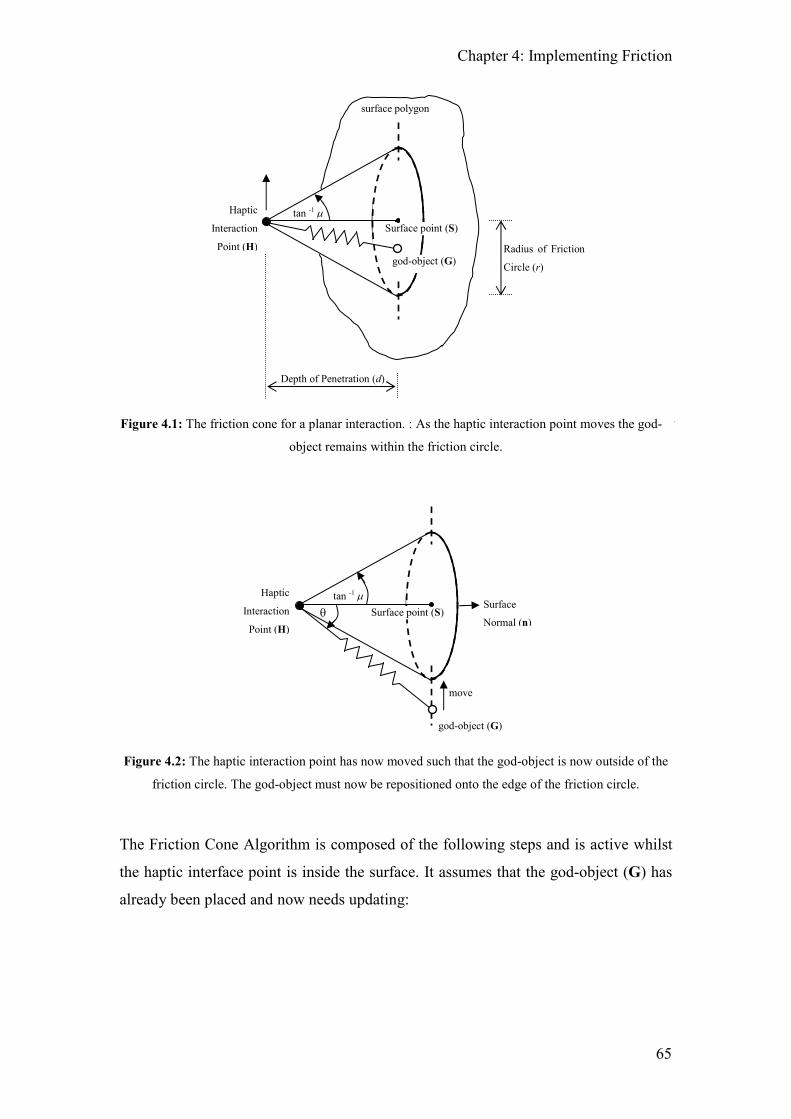
Chapter 4: Implementing Friction
65
Figure 4.1: The friction cone for a planar interaction. : As the haptic interaction point moves the god-
object remains within the friction circle.
Figure 4.2: The haptic interaction point has now moved such that the god-object is now outside of the
friction circle. The god-object must now be repositioned onto the edge of the friction circle.
The Friction Cone Algorithm is composed of the following steps and is active whilst
the haptic interface point is inside the surface. It assumes that the god-object (G) has
already been placed and now needs updating:
θ Surface point (S)
god-object (G)
tan -1 µ Surface
Normal (n)
Haptic
Interaction
Point (H)
move
Haptic
Interaction
Point (H)
tan -1 µ
surface polygon
Surface point (S)
god-object (G)
Depth of Penetration (d)
Radius of Friction
Circle (r)

Chapter 4: Implementing Friction
66
1. Calculate the depth of penetration (d) of the haptic interaction point (H) below
the surface of the polygon as in equation [4.3].
( )d = −H G ni , where n is the unit normal of the surface. [4.3]
2. Calculate the location of the surface point (S). The surface point lies on the
contacted surface and is defined as the minimum distance between the haptic
interaction point and the contacted surface. This calculation is shown in
equation [4.4].
d= +S H n [4.4]
3. A circle can then be considered as the intersection of the friction cone with the
surface polygon. The radius of this friction cone circle (r) is given by equation
[4.2].
4. The distance between the surface point and the god-object (Ds-g) is then given
by equation [4.5]. This distance is then compared to the radius of the friction
circle.[4.5]
= −SPGOD G S [4.5]
5. If the god-object is outside the friction circle then update the god-object’s
position to be on the perimeter of the friction circle using equation [4.6],
otherwise leave the god-object in place.
( )
new r−
= +SPGO
G SG S
D [4.6]
6. The response force (Fresp) can now be calculated based upon the vector from
the haptic interaction point to the god-object and will be proportional to the
surface stiffness (k).

Chapter 4: Implementing Friction
67
( )resp k= −new
F H G [4.7]
Thus when the god-object is outside the friction cone it will ‘jump’ to the closest point
on the circumference of the friction circle, shown in Figure 4.2, and provides the
equivalent to static friction. In its current form, the coulomb model of friction is being
modelled (Figure 3.4(b)).
4.1.1 Modelling Static, Dynamic and Viscous Friction
More complex friction models can be simulated by tracking the state of the system.
For the stick-slip friction model shown in Figure 3.4(d), the system has two states:
stuck (static) and slip (dynamic). Unlike the coulomb model of friction, a
characteristic of this model is that the coefficient of static friction (µs) is greater than
the dynamic friction coefficient (µd).
A state change from stuck to slip occurs the first time that the god-object needs to be
moved. When this occurs it is necessary to replace the static friction coefficient with
the coefficient of dynamic friction (µd) in equation [4.2] and to reposition the god-
object onto the edge of the new friction circle as per equation [4.6]. To affect a state
change from slip to stuck it is necessary that the angle between the vector from the
haptic interaction point to the god-object and the surface normal (the angle θ in Figure
4.2) is less than the coefficient of dynamic friction (µd). Using the Friction Cone
Algorithm, this will occur when the god-object does not require moving.
Figure 4.3: State transition diagram between dynamic (coloumb) and static friction conditions.
Changes in the angle at the haptic interaction point (θ), between the god-object and the surface point
triggers a state change.
STUCK
use µs SLIP
use µd
θ > tan-1
µs
θ < tan-1
µd θ > tan -1
µd

Chapter 4: Implementing Friction
68
Viscous friction can only occur when the system is moving and it is proportional to
the velocity of movement in the opposing direction. To model viscous friction it
becomes necessary to track the velocity of the god-object. The friction due to the
viscous component can then be calculated and this is then added onto the other
frictional forces. Using the Friction Cone Algorithm this can be achieved by
increasing the size of the friction cone based upon the current speed of the god-object
i.e. by changing the friction coefficient used in equation [4.2].
If µv is the coefficient of viscous friction and s is the speed that the god-object is
travelling, µvd , the friction coefficient incorporating both the dynamic and viscous
component, can be calculated as follows:
( )vd d vsµ µ µ= + [4.8]
The friction model shown in Figure 3.4(c) can be modelled by using µs (static friction
coefficient) in place of µd (dynamic friction coefficient) in equation [4.8].
4.1.2 Modelling Arbitrarily Complex Friction Models
Using the Friction Cone Algorithm mechanism, it is possible to accurately model
complex friction models provided that it can be expressed in a Friction vs. Velocity
graph as used in the friction models shown in Figure 3.4. It is necessary to determine
the number of states that are required, what causes these states to transition and how
the size of the friction cone changes when in each of these states.
4.2 Applying the Friction Cone Algorithm to Polygon
Meshes and Curved Surfaces
In order for the Friction Cone Algorithm to be a useful tool for haptic rendering, it is
necessary that it can be applied to complex objects. Polygon meshes and parametric
objects are methods that are used to represent complex objects and it is possible to
apply the Friction Cone Algorithm to haptically render these different surfaces.

Chapter 4: Implementing Friction
69
In order to use the Friction Cone Algorithm for haptic rendering, it is necessary to be
able to find the normal of the surface at the point where the initial collision occurred
as well as the normal at the position of the god-object.
4.2.1 Simple Parametric Objects
Parametric objects have surfaces that can be described through a mathematical
equation and include planes, spheres, cones, cylinders and tori. With the exception of
the plane, a characteristic of parametric surfaces is that they are curved.
Applying the Friction Cone Algorithm to a parametric surface requires the same steps
used for a plane with two modifications. The first modification requires the
generation of a plane when the god-object is initially placed. The second
modification affects the algorithm when the god-object is moved.
Figure 4.4: a) The god-object needs to be repositioned back onto the sphere’s surface. b) The god-
object has been repositioned onto the sphere and the new temporary plane has been calculated.
A sphere with centre ccircle and radius rcircle (see Figure 4.4) is used as an example
although the same method is applicable to all types of simple parametric objects.
Upon initial placement of the god-object (G) a temporary plane needs to be created:
1. Define a plane (using normal n and distance from origin D) that passes
through the god-object.
= Original position of god-object
= New Position of god-object
= Temporary plane for god-object to
ccircle rcircle
a) b)

Chapter 4: Implementing Friction
70
circle= −v c G [4.9]
=v
nv [4.10]
circleD r= [4.11]
2. The Friction Cone Algorithm is then applied as described for the plane until
the god-object must be moved. In this case the god-object is repositioned on
the plane as before but it then needs to be repositioned back onto the
parametric surface. For the sphere the new position for the god-object is
calculated as follows:
circle plane= −v c G [4.12]
=v
nv [4.13]
circle circler=G n [4.14]
3. The temporary plane that the Friction Cone Algorithm is applied to must then
be recalculated as described in equations [4.12], [4.13] and [4.14].
In order to apply the Friction Cone Algorithm onto parametric objects in this way it is
necessary to be able to calculate where the god-object should be placed and this
information is usually returned from a ray-object intersection test. Using this
approach, the Friction Cone Algorithm has been applied to parametric spheres,
cylinders, cones and torii.
When traversing very tightly curved parametric objects it may appear that there is a
potential issue with stability. This would occur when the radius of the curve being
traversed is very small which may cause the direction of the force applied to the user
to change greatly when the god-object is repositioned. In order for this to happen the
radius of the curve will need to be close to the sensor resolution of the haptic device
and as such the force that will be applied to the user will also be very small. Further
to this, because the god-object always lags behind the haptic interaction point, the
haptic interaction point will most likely exit the contacted object ending any forces

Chapter 4: Implementing Friction
71
that were being applied. Because of these reasons, the author does not see this as an
issue that warrants concern.
4.2.2 Single NURBS surfaces
NURBS (Non-Uniform Rational B-Splines) are a generalised parametric means of
describing an object’s surface, are used extensively in CAD, and are ideally suited for
the creation of ‘organic’ objects that feature many curved surfaces. Methods
proposed by Thompson and Cohen [Thompson99] and Patoglu and Gillespie [Patoglu05]
can be applied to the haptic rendering of NURBS surfaces but due to the highly
mathematical nature of this type of surface these methods are computationally
expensive. This is due to the fact that there is no simple solution to finding where a
ray collides with the NURBS surface which is necessary for calculating the depth of
penetration and surface normal. The only way to calculate this point is to use an
iterative method that will converge on the desired location. However, work done with
Russell [Russell04] has applied the Friction Cone Algorithm to the rendering of a
single NURBS surfaces with success although, due to the comparative inefficiency of
the ray-NURBS intersection tests, further work allowing for crossing over onto
adjoining NURBS surfaces was not undertaken.
NURBS surfaces are rendered in the same way as the simple parametric objects.
Upon initial contact, a plane must be placed at the contact point where the normal on
the surface at this point can be determined from the equations defining the NURBS
surface. When the god-object needs to be repositioned it should first be repositioned
on this plane and then moved back onto the surface. This requires that the point of
intersection between a ray and the surface is found where the ray originates at the
haptic interaction point in the direction of the currently repositioned god-object.
4.2.3 Polygon Meshes
Polygon meshes are perhaps the most common means of representing a 3D model and
as such a large number of haptic rendering methods exist for rendering polygon
meshes. Unlike parametric objects, polygon meshes are constructed from planar faces
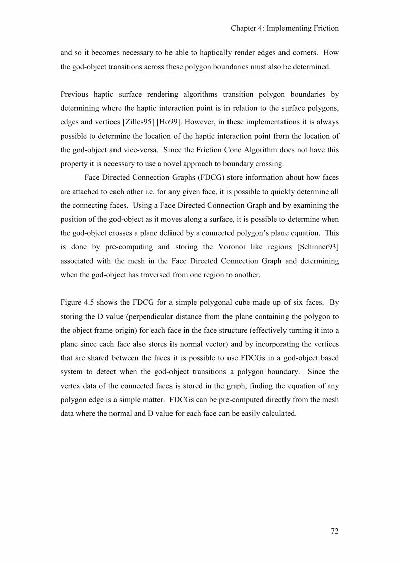
Chapter 4: Implementing Friction
72
and so it becomes necessary to be able to haptically render edges and corners. How
the god-object transitions across these polygon boundaries must also be determined.
Previous haptic surface rendering algorithms transition polygon boundaries by
determining where the haptic interaction point is in relation to the surface polygons,
edges and vertices [Zilles95] [Ho99]. However, in these implementations it is always
possible to determine the location of the haptic interaction point from the location of
the god-object and vice-versa. Since the Friction Cone Algorithm does not have this
property it is necessary to use a novel approach to boundary crossing.
Face Directed Connection Graphs (FDCG) store information about how faces
are attached to each other i.e. for any given face, it is possible to quickly determine all
the connecting faces. Using a Face Directed Connection Graph and by examining the
position of the god-object as it moves along a surface, it is possible to determine when
the god-object crosses a plane defined by a connected polygon’s plane equation. This
is done by pre-computing and storing the Voronoi like regions [Schinner93]
associated with the mesh in the Face Directed Connection Graph and determining
when the god-object has traversed from one region to another.
Figure 4.5 shows the FDCG for a simple polygonal cube made up of six faces. By
storing the D value (perpendicular distance from the plane containing the polygon to
the object frame origin) for each face in the face structure (effectively turning it into a
plane since each face also stores its normal vector) and by incorporating the vertices
that are shared between the faces it is possible to use FDCGs in a god-object based
system to detect when the god-object transitions a polygon boundary. Since the
vertex data of the connected faces is stored in the graph, finding the equation of any
polygon edge is a simple matter. FDCGs can be pre-computed directly from the mesh
data where the normal and D value for each face can be easily calculated.

Chapter 4: Implementing Friction
73
Figure 4.5: A simple cube consisting of six faces and its associated Face Directed Connection Graph
Storing a polygon mesh requires that the faces and vertices are stored in an object
structure. Implementing a FDCG requires that the connections between the faces are
known and since the connection between two polygons is an edge it is possible to
store the FDCG in the object structure to avoid data duplication.
The connection structure must contain the following:
SharedVertex(x2) - the two shared vertices
Face(x2) - the two connected faces
EdgeVector - normalised vector from SharedVertex(1) to
SharedVertex(2)
ConnectionType - connection type (is either convex, concave or coplanar)
VoronoiPlane(x2) - see below for explanation
EndPlane(x2) - see below for explanation
It is also necessary to modify the face and vertex structure. The face structure must
also store the following information:
FaceNormal - the normal of this face
ConnectionArray - array of connections to this face
The Vertex structure must also contain the following:
ConnectionArray - array of connections that share this corner
F1
F6
F3 F2
F5
F4
F1 = Top face F2 = Bottom face F3 = Right face F4 = Left face F5 = Front face F6 = Back face

Chapter 4: Implementing Friction
74
The Voronoi planes in the connections are associated with the two connected faces
such that VoronoiPlane(1) is the Voronoi plane for Face(1) and VoronoiPlane(2) is
the Voronoi plane for Face(2). The Voronoi plane is simply a plane that passes
through the two, shared vertices with a normal perpendicular to the normal of the
associated node, a two-dimensional representation is shown in Figure 4.6:.
Figure 4.6: Two connected faces and their associated Voronoi regions.
Each Voronoi plane requires a normal and a perpendicular distance to the origin or
‘D’ value which are calculated as follows where p1 and p2 correspond to shared
vertices one and two, respectively and nface is the normal of the associated polygon
face.
3 face 2 =p n + p [4.15]
1 2= −1
v p p [4.16]
2 1 3= −v p p [4.17]
= ×1 2
n v v [4.18]
Voronoi plane normal =n
n [4.19]
Voronoi plane D ( )= −1
v ni [4.20]
Similarly, the end planes are associated with the two shared vertices. Each of the
shared vertices lie on an end plane and the normal is either the edge vector or the
negative edge vector of the connection.
= Voronoi Region associated with the polygon faces
Face 2
Face 1
= Face normal = Voronoi Plane normal

Chapter 4: Implementing Friction
75
When computing the Voronoi and end planes, it is important to ensure that a
consistent winding is used in the mesh data structure and that this is translated into the
connections in the FDCG otherwise the direction of the computed normals for the
Voronoi planes may be incorrect leading to unpredictable transitions between the
affected polygons.
4.2.4 Crossing Polygon Boundaries
As the god-object moves across the object’s surface there are a number of state
changes that can occur, i.e. moving from a face to an edge etc. These are shown in
Figure 4.7.
Figure 4.7: State transition diagram showing how a god-object’s state changes as it moves across the
surface of a polygon based object.
There are two types of transition and these are determined by the apparent number of
degrees of freedom that are affected. The degenerate transitions occur when the
available degrees of freedom decreases and include free-space (3DOF) to face
(2DOF), face to edge (1 DOF) and edge to vertex (0 DOF). These transitions are
determined by how the god-object moves. The regenerate transitions occur when the
apparent available DOF increases. These include vertex to edge, vertex to face, edge
to face and vertex/edge/face to free-space and are determined by the movement of the
haptic interaction point.
The degenerate transitions only need to be checked when the god-object is moved
whereas the regenerate transitions need to be checked every time the haptic
interaction point moves.
F
FS
E V
FS = Free-space F = Face E = Edge V = Vertex

Chapter 4: Implementing Friction
76
4.2.4.1 Free-Space to Face Transitions
This is determined by the collision detection algorithm and will define the initial
active face.
4.2.4.2 Face to Edge Transitions
A face to edge transition will occur when the god-object crosses one of the Voronoi
planes associated with the face, i.e. it moves into the Voronoi region associated with
the edge. This can be achieved by comparing the distance of the god-object to the
Voronoi planes stored in the connections that are attached to the currently active face.
Since the Voronoi planes are generated from polygons with consistent winding, it is
easy to determine which side of the Voronoi planes the god-object is on based upon
the sign of the calculated distance. If it has been determined that a Voronoi plane has
been crossed, then the associated connection has been transitioned and the
corresponding edge is made active (see section 4.2.5 for using the Friction Cone
Algorithm on edges). The god-object is then repositioned on the edge where the
transition occurred. This process can be seen in Figure 4.8 .
Figure 4.8: God-object crossing from a face to an edge.
4.2.4.3 Edge to Vertex Transitions
An edge to vertex transition occurs when the god-object moves off the end of the edge
i.e. the god-object crosses an associated end plane. If the god-object has passed an
end plane, then the corresponding vertex is made active and the god-object is
repositioned at the active vertex.
GO on Polygon 1 GO crosses voronoi plane
associated with the edge
P2
P1
P2
P1
= God-object (GO)
= Old God-object position
= Voronoi Region associated with polygon 1
= Voronoi Region associated with polygon 2
P1
P2
GO is repositrioned on the
edge

Chapter 4: Implementing Friction
77
4.2.4.4 Face to Free-Space Transitions
A face to free-space transition can be determined by the distance of the haptic
interaction point to the face plane; if the distance is positive, then the haptic
interaction point has transitioned out of the plane and is thus in free space.
4.2.4.5 Edge to Free-Space Transitions
There are two types of edge to free-space transition: when the edge is acute and
convex, and when it is not.
Figure 4.9: Transitioning from a convex edge into free space
Figure 4.9 shows the position of the haptic interaction point and the god-object when
an acute, convex edge is first made active (i.e. the edge has been made active but no
transitions have yet been determined). If the haptic interaction point is in front of one
connected face plane and behind the other face plane then an edge to free-space
transition will occur.
The second edge to free-space transition occurs when the haptic interaction point is in
front of both of the connected face planes at the same time.
4.2.4.6 Vertex to Free-Space
A vertex to free-space transition occurs when the haptic interaction point is in front of
all the connected planes.
= God-Object attached to edge
= Haptic Interaction Point
= Face normal
= Spring that force
is directed along

Chapter 4: Implementing Friction
78
4.2.4.7 Edge to Face
An edge to face transition will occur when the haptic interaction point moves into a
face Voronoi region, at which point the corresponding face is made active. However,
if the current edge is convex, it may be possible for the haptic interaction point to be
behind both Voronoi planes stored in the connection. In this case, the face plane that
the haptic interaction point is closest to is made active. In either case, the god-object
does not need to be repositioned. Figure 4.10 shows the edge-face transition for a
non-convex case.
Figure 4.10: Haptic interaction point entering a shaded region in this non-convex example causes an
edge to face transition to occur.
4.2.4.8 Vertex to Edge
This transition will occur if the haptic interaction point moves into the edge Voronoi
region, i.e. it is behind both face planes that are stored in a connection connected to
this corner.
4.2.5 The Friction Cone Algorithm on an Edge
A slight modification to the Friction Cone Algorithm is required in order to allow it to
work on an edge. When in contact with a face, the surface point is defined as the
minimum distance between the haptic interaction point and the contacted surface and
can be easily calculated since the face normal is known, see equation [4.4]. However,
= God-Object
= HIP when edge should be active
= HIP when face should be active
= Face normal
=Area where face
should be active

Chapter 4: Implementing Friction
79
in the case of an edge there is no normal to use so an alternative method is required to
find the surface point. Equations [4.21] through [4.24] and Figure 4.11 show how to
calculate a point on the edge that is perpendicular to the haptic interaction point which
can then be used to define the surface point.
Figure 4.11: Calculating the surface point when on an edge
Two vectors, ve and vw are defined as:
2 1e = −v p p [4.21]
1w =v H - p [4.22]
By projecting vw onto ve the surface point can be calculated as:
w e
e e
b
=
v v
v v
i
i
[4.23]
1 eb=S p + v [4.24]
Once the surface point has been determined, the distance between the surface point
and god-object can be calculated as before (see [4.5]) and, if necessary, the god-object
should be moved as per [4.6].
4.2.6 Smoothing Polygon Transitions Using Force Shading
In order to smooth polygon transitions, force shading can be implemented with the
Friction Cone Algorithm. Force shading is analogous to graphical Phong shading in
that it modifies the normal across the face of the polygon to make it appear smooth
Vw
P1 S
Ve
H
P2
p1, p2 = Vertices defining the edge
H = Haptic Interaction Point
Ve = Edge vector as defined in Section 4
S = Surface Point

Chapter 4: Implementing Friction
80
instead of faceted. Unlike the implementations described by Ho [Ho99], Zilles
[Zilles95] or Ruspini [Ruspini97], because the Friction Cone Algorithm does not
return the normal force of a virtual contact, but the normal and frictional forces a
novel approach to polygon smoothing is required. Instead it is necessary to
interpolate the surface normal and use the interpolated normal to rotate the output
force vector. In order to achieve this, the vertex definition as defined above for use
with FDCGs must be modified to include a normal at the vertex. The actual Friction
Cone Algorithm remains unchanged.
Figure 4.12 shows a 2D example of how the normal should be interpolated along a
surface and the method described by Ho et al. [Ho99] to calculate the interpolated
normal is repeated here for convenience.
Figure 4.12: 2D example of how the normal should be interpolated. The dotted line is the apparent
surface that is felt.
Provided that the haptic model is made from triangles, during haptic rendering the
vertices of the unshaded polygon are retrieved and the contacted polygon is
subdivided into triangles as shown in Figure 4.13.

Chapter 4: Implementing Friction
81
Figure 4.13: A contacted polygon and the associated sub-triangles and normals (Adapted from
[Ho99]).
From [Ho99], the interpolated normal (nc) at the contact point (the god-object) can
then be calculated by averaging the vertex normals (ni) weighted by the areas (Ai) of
the three subtriangles, i.e:
3
1
3
1
i i
ic
i
i
A
A
=
=
=∑
∑
n
n [4.25]
Once the interpolated normal has been determined, the output force (fnew) (containing
any frictional components) can be calculated as follows:
c cur cur= +1f n f f , where fcur is the current force vector [4.26]
new cur
=
1
1
ff f
f [4.27]
A beneficial side effect when using this method of force shading is that it no longer
becomes necessary to transition from one face to an adjoining face via an edge since,
at the point of transition, the haptic interaction point will already be in the adjoining
face’s Voronoi region.
N1
N2
N3
A1 A2
A3
= Normal
= Vertex

Chapter 4: Implementing Friction
82
However, this method of force shading may not be ideal as it causes the entire object
to have a ‘rounded’ feel. In many situations it is probably preferable to keep large flat
areas correctly rendered and only apply force shading when approaching an edge.
This can be achieved by having a ‘region of activation’, a fixed distance from the
polygon’s edges demonstrated in Figure 4.14. If this approach is used the interpolated
normal is calculated by combining a ratio of the normals of the two connected
polygons based upon the distance from the polygon’s edge. This calculation is shown
in equations [4.28] and [4.29] with Distedge denoting the distance from the shared
edge, l the length of the activation region and n1and n2, the unit normals of the current
polygon and the polygon being approached, respectively.
edgeDist
lα = [4.28]
1 2 (1 )c α α= + −n n n [4.29]
Figure 4.14: Force shading using ‘regions of activation’ method. Interpolation is only applied when
the god-object is inside a region of activation.
It is possible that the god-object may lie within two or more regions of activation. In
these cases it is necessary to interpolate the normal for each region of activation in
series, i.e. calculate the interpolated normal for the first region as described above,
and then use the interpolated normal just calculated in place of n1 for the subsequent
regions.
= 1 region active
= 2 regions active
= activation region boundary

Chapter 4: Implementing Friction
83
4.2.7 Height Mapping
Bump mapping is a graphical technique that can be used to simulate small features
over an object’s surface and works by determining the normal used for the lighting
calculation from a 2D texture map. Haptically, bump maps can be used to portray
surface texture and Ho et al. [Ho99] describes a method to haptically render bump
maps by taking into account the normal and height of each bump. They also describe
methods to allow the haptic interaction point to collide with the ‘bumps’ on the bump
mapped surface and not just the flat surface. However, most haptic interfaces are
unable to provide the high spatial frequencies needed to render bump maps correctly
[Wall00b] but this level of realistic modelling and added computational complexity is
not necessary to convincingly render bump maps especially since the ‘bumps’ on
surfaces are only felt when moving along the surface. Instead, it is possible to
convincingly render a bumpy surface by using a ‘height map’ instead of a bump map.
The pixels in the height map correspond to a height value that should be added or
subtracted from the contacted surface. By determining the value of the height map at
the contact point (god-object) this value is added to (in the direction of) the force
vector output from the Friction Cone Algorithm to simulate the bumps.
4.3 Chapter Summary
This chapter has described the Friction Cone Algorithm to the reader. It has been
shown how the Friction Cone Algorithm can be used to simulate different friction
models and it has also been demonstrated how it can be applied to a number of
different 3D representations including polygon meshes, parametric objects and
NURBS surfaces. Since the Friction Cone Algorithm incorporates friction into the
actual contact algorithm, when using the Friction Cone Algorithm, it is no longer
necessary to add in any extra lateral forces to simulate friction. It can also be seen
that the Friction Cone Algorithm is entirely vector based which makes it both easy to
implement as well as very processor efficient. Further to this, its parameters have a
simple physical interpretation. Another feature of the Friction Cone Algorithm is that
it is time free since only positional information is required in its formulation. This is
important for two reasons: since it requires no time information (such as velocity)
there are no issues when travelling at near zero speeds when simulating stick-slip

Chapter 4: Implementing Friction
84
friction (unlike other implementation) and the output is guaranteed to be free from
numerical drift over time.

85
5 Multi-Finger Manipulation Physics
With multiple points of contact it is possible to grasp and manipulate an object in a
natural manner. This chapter is concerned with the issues that arise when using
multiple, discrete haptic devices as well as the physics involved to manipulate a
grasped object. A method is given to calculate the transformation matrices required to
allow multiple, discrete devices to work in the same coordinate space and the
Residual Force and Torque Algorithms are described which allow a grasped object to
be manipulated in a natural manner. Methods are also given that allow an object to be
manipulated naturally when only two points of contact are made.
5.1 Possible Types of Grasp with the Hardware Used
Figure 5.1: The three finger Phantom configuration used for conducting this research. This setup was
chosen as it maximises the available workspace for translations and rotations of virtual objects without
the mechanical arms colliding. This is the right hand setup.
Due to the hardware that was used for this research, methods were only investigated
for precision grip manipulations. Within the subset of the precision grasps there are
three distinct ways in which an object can be manipulated: Single finger, two finger
and three or more fingers. It is necessary to consider these three types of interactions
as they represent the various levels of stable grasp that can be achieved. Section 2.6.1

Chapter 5: Multi-Finger Manipulation Physics
86
and Section 3.3 include more information upon the various types of grasps that can be
made.
5.1.1 Types of Grasps
The term ‘stability’ can have two meanings in the context of grasp: spatial grasp
stability and contact grasp stability. Spatial grasp stability is the ability to return a
grasped object to its static equilibrium when its position is changed. This meaning of
stability is directly related to the manipulation of the object. Contact grasp stability is
the ability to maintain the contact against any external forces or disturbances that are
also acting on the object. When grasp stability is discussed in this thesis it is the
former meaning of stability that is used.
A lot of research has been done on stable grasps in the field of robotics as well as in
psychology. For spatial grasp stability, Salisbury [Salisbury82] defined a grasp
matrix quantity and showed that provided that this matrix has sufficient rank then the
contact points can apply force and torques in arbitrary directions whilst maintaining a
stable spatial grasp (this type of grasp is said to have achieved force closure).
Salisbury only categorises a grasp as being (spatially) stable or unstable and does not
distinguish between the different types of stable grasps. It has also been shown that
the addition of friction at the points of contact is beneficial since it allows a spatially
stable grasp to be achieved with fewer contact points then would otherwise be
required. For contact grasps Cutkosky and Wright [Cutkosky86] analysed contact
grasp stability with human like fingertips and show that the visco-elastic nature of
finger tips enhanced contact stability. [Montana91] showed that there were a number
of factors that affected grasp stability and how it is not possible to talk of a stable
grasp without considering both the spatial and contact grasp stabilities simultaneously.
He shows that there are a number of factors that affect contact grasp stability, namely,
object curvature, contact size (i.e. flat fingertips versus pointed contacts) and distance
between contacts. By looking at the contact kinematics a model of the grasp dynamics
and hence the grasp stability can be created.
In terms of spatial grasp stability, a fully stable grasp allows an object to be
manipulated in six degrees of freedom, three translational and three rotational. With

Chapter 5: Multi-Finger Manipulation Physics
87
the inclusion of translational friction at the contact points it is possible to create a fully
stable grasp, with six degrees of freedom, with only three non-collinear points of
contact. With the addition of torsional friction at the contact points, two contact
points can be used to achieve a stable grasp with two rotational and three translational
degrees of freedom. With a single point of contact only a ‘pole balance’ or a single
finger lift, can be achieved. The pole balance is an unstable grasp and has no
controllable rotational or translational degrees of freedom. Although the single finger
lift allows for three translational degrees of freedom, in the absence or torsional
friction at the contact point, there are no rotational degrees of freedom. In the absence
of gravity or other external forces, only a fully stable grasp can be used to achieve full
rotational and translational degrees of freedom.
5.2 Calibration of Multiple Discrete Devices
Since a number of discrete, single finger haptic devices are used instead of a single
multi-finger device it is necessary to calibrate all the haptic devices into a single
coordinate frame. In order to achieve this calibration, one device needs to be
designated as the fiducial. It is assumed that it is already known how to transform the
fiducial’s coordinate frame into the coordinate frame of the virtual world.
The method described here can then be used to calibrate any number of devices with
respect to the fiducial. Note, the end point position data that is required needs to be
four elements long since a 4x4 homogenous transform is calculated. This can be
achieved by outputting x, y, z, 1 for each logged entry.
1 Assume FT (θF) is the transform of the fiducial based on the three measured
angles θF. Similarly, NT (θN) is the transform of the other devices(s).
2 End point position data is then gathered by holding the device endpoints
together and moving them around.

Chapter 5: Multi-Finger Manipulation Physics
88
3 For the fiducial, the gathered points in the world coordinate frame is given by:
( )W F W
world F F F F FP T T P TPθ ′= = [5.1]
where: PF = Points in the fiducial coordinate frame
W
FT = Transform to get these points into the world coordinate frame
4 Similarly, the gathered points for the other device is given by:
( ) 'W N W
world N F N N NP T T P TPθ= = [5.2]
where: PN = Points in the ‘other’ coordinate frame
W
NT = Transform to get these points into the world coordinate frame
5 By adding a correction matrix (A) we have:
( ) ( )'
'
W W W
world F F W N NP TP A TP= = [5.3]
6 The correction matrix can then be found in the least squares sense by using
singular value decomposition, left division if available or pseudo least squares,
i.e.
( ) ( ) 1
' '/W W N W T T N
W F F N W F F N N N WA T P P T TP P P P T−
= = [5.4]
where: 1'
'
−= TT W
N
N
W and ' / ' indicates left matrix division (a numerically robust
method of calculating PF / PN ). The third equality is the pseudo least
squares version.
7 If the devices are perfectly calibrated then A will be a 4x4 identity matrix.

Chapter 5: Multi-Finger Manipulation Physics
89
By using the described calibration method, the end points of both devices will be
mapped to the same position. Figure 5.2 contains the Matlab implementation of the
above calibration method. The CalibDataFile contains six columns containing the
raw x, y, z values of Phantom0 (fiducial) followed by the raw x, y, z values of
Phantom1. T1 is the calibration matrix generated by this set of data.
function [T1] = calibratePhant1(CalibDataFile)
%Calibrates 1 phantom to the Fiduccial
%Load in the supplied file name
CalibData = load(CalibDataFile);
% load in data
phm0 = CalibData(:,1:3);
phm1 = CalibData(:,4:6);
% add in extra column of 1s to make homogeneous
len = length(phm0);
pm0=[phm0 ones(len,1)];
pm1=[phm1 ones(len,1)];
% calculate new Transform
T1=pm0'/ pm1';
Figure 5.2: The Matlab implementation of the calibration routine described.
In order to use this algorithm, it is necessary that both endpoints are kept constantly in
exactly the same place. In order to achieve this, a tool was made that replaces both
endpoints for the Phantoms and was precisely engineered to an accuracy of < 0.1mm.
5.3 Manipulating Objects - The Residual Force and Torque
Algorithms
In order to be able to manipulate an object it is necessary to be able to determine all
the forces and torques that are acting on the object. These forces will include finger

Chapter 5: Multi-Finger Manipulation Physics
90
contact forces as well as environmental forces such as gravity. Finger contact forces
can be generated using either the Friction Cone Algorithm as described in Chapter 3
or by other means although the descriptions assume that the Friction Cone Algorithm
was used to generate the contact forces.
5.3.1 The Residual Force and Torque Algorithms
Given that a collision algorithm has identified a number of points of contact and the
estimated instantaneous contact forces have been calculated, it is now necessary to
estimate residual forces and torques on the object. Translation and rotation of the
object will then be subject to these residual forces and torques until a state of static
equilibrium is reached. The simplest method is to sum torques and forces at the
object’s centre of mass and integrate residuals to achieve the object’s rotational and
linear velocity and subsequently the object’s orientation and position.
Figure 5.3: Force estimates for an object with three contact points. f1, f2 and f3 are the force vectors
applied to the object by the individual contact points and r1, r2 and r3 are the vectors from the centre of
mass to the contact point.
Figure 5.3 shows the force estimates based on three friction cones due to a three point
contact of an object. Residual forces and torques at the Centre of Mass of the body
can then be calculated.
The Residual Force Algorithm calculates the residual force in the object based upon
all forces that are being applied to the object. These forces include, but are not
limited to, forces generated from the Friction Cone Algorithm due to contact as well
as gravity. Similarly, the Residual Torque Algorithm calculates the residual torque in
the object.
CofM
r1
r2
r3
f2
f3 f1
mg
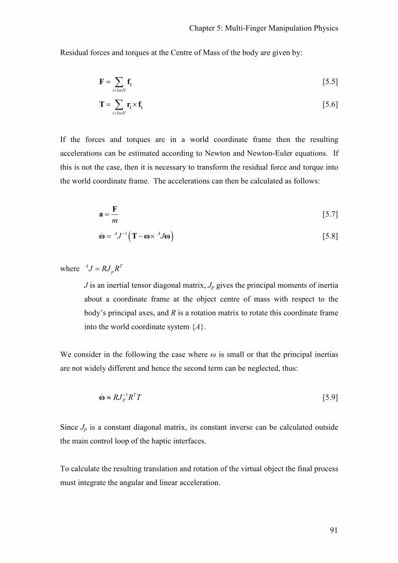
Chapter 5: Multi-Finger Manipulation Physics
91
Residual forces and torques at the Centre of Mass of the body are given by:
1i toN=
= ∑ iF f [5.5]
1i toN=
= ×∑ i iT r f [5.6]
If the forces and torques are in a world coordinate frame then the resulting
accelerations can be estimated according to Newton and Newton-Euler equations. If
this is not the case, then it is necessary to transform the residual force and torque into
the world coordinate frame. The accelerations can then be calculated as follows:
m
=F
a [5.7]
( )1A AJ J−= − ×ω T ω ω� [5.8]
where A T
pJ RJ R=
J is an inertial tensor diagonal matrix, Jp gives the principal moments of inertia
about a coordinate frame at the object centre of mass with respect to the
body’s principal axes, and R is a rotation matrix to rotate this coordinate frame
into the world coordinate system {A}.
We consider in the following the case where ω is small or that the principal inertias
are not widely different and hence the second term can be neglected, thus:
1 T
PRJ R T−≈ω� [5.9]
Since Jp is a constant diagonal matrix, its constant inverse can be calculated outside
the main control loop of the haptic interfaces.
To calculate the resulting translation and rotation of the virtual object the final process
must integrate the angular and linear acceleration.

Chapter 5: Multi-Finger Manipulation Physics
92
Given the loop time (∆t) of the control algorithm the velocity (v) and position (p)
estimates can be arrived as follows:
t= + ∆oldv v α [5.10]
t= + ∆oldp p v [5.11]
The angular velocity (ω) and orientation (R) estimates are:
t= + ∆oldω ω ω� [5.12]
R I S t∆ = + ∆ [5.13]
oldR R R= ∆ [5.14]
where:
0
0
0
z y
z x
y x
S
ω ωω ωω ω
−
= − −
and I is the identity matrix
Since [5.13] is a small angle approximation of rotation it is necessary to normalise R,
i.e. if R is composed of three unit vectors R=[n o a]:
1. Set a = a / | a |,
2. Set n perpendicular to a and o and then normalise,
i.e. n = o × a , n = n / | n |
3. Set o perpendicular to a and n with o = a × n
5.3.2 Analysis of the Rotation Method
Expanding equation [5.8] gives:
1 1T TRJ R T RJ R− −= − ×ω ω ω� [5.15]
In normal use we can expect ω to be small so ignoring the second term has no
noticeable effects. This is because the second term is concerned with effects at high
rotational velocity, such as in a gyroscope. Inclusion of this term allows the Coriolis

Chapter 5: Multi-Finger Manipulation Physics
93
force (a torque perpendicular to the axis of rotation) to be generated when a spinning
object is tilted.
5.3.3 Two Finger Grasps and Soft Finger Contact Modelling
Where a multi-contact point haptic interface is used to grasp a virtual object at two
points it will not be possible to rotate that object along an axis joining the two god-
objects. In this case the three point contact grasp algorithm can still be used to rotate
the object in the direction of the remaining orientation degrees of freedom. To
achieve a rotation in the plane perpendicular to this original grasp axis, either the two
finger grasp must be remade, or the object reoriented in a non-intuitive way to allow
rotation in this axis. In the real world, a two finger grasp of an object does allow free
rotations in all three degrees of freedom because friction between the finger pads and
the object can be used to apply a torque around this axis. Trying to simulate this
torsional friction between the object and the finger tips is known as soft finger contact
modelling.
Two mechanisms can be used to simulate rotations about this axis due to finger pad
torsional friction. Since, in real interactions, the finger pad area can be considered
approximately proportional to the applied pressure, we can use the area of the friction
circle as an approximate indicator of the available frictional torque available to allow
these finger pad determined rotations. If the Friction Cone Algorithm is not used to
generate the contact force, then a proportion of the force normal to the contacted
surface can be used.
5.3.3.1 Instrumented Gimbals
If a Phantom with an instrumented gimbal is used for one or more of these contact
points then a coordinate frame can be established on the object such that the x-axis is
along the line joining the two god-objects, the y-axis is along the normal joining the
centre of mass to this line, and the z-axis is perpendicular forming a right handed
coordinate frame. Once the area of the friction circle (A) exceeds a critical value (Acrit)
the gimbal pitch measurement can be used to rotate this coordinate frame around the
x-axis and hence update the rotation matrix and the position vector defining the
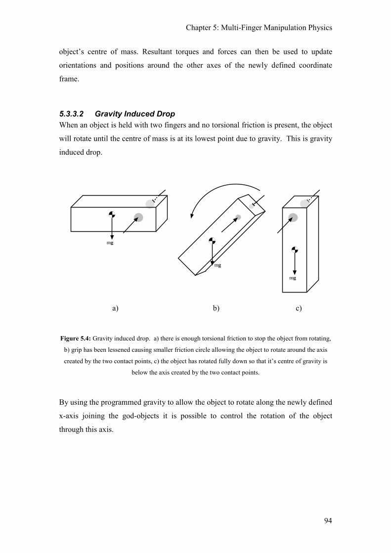
Chapter 5: Multi-Finger Manipulation Physics
94
object’s centre of mass. Resultant torques and forces can then be used to update
orientations and positions around the other axes of the newly defined coordinate
frame.
5.3.3.2 Gravity Induced Drop
When an object is held with two fingers and no torsional friction is present, the object
will rotate until the centre of mass is at its lowest point due to gravity. This is gravity
induced drop.
mg
mg
mg
a) b) c)
Figure 5.4: Gravity induced drop. a) there is enough torsional friction to stop the object from rotating,
b) grip has been lessened causing smaller friction circle allowing the object to rotate around the axis
created by the two contact points, c) the object has rotated fully down so that it’s centre of gravity is
below the axis created by the two contact points.
By using the programmed gravity to allow the object to rotate along the newly defined
x-axis joining the god-objects it is possible to control the rotation of the object
through this axis.
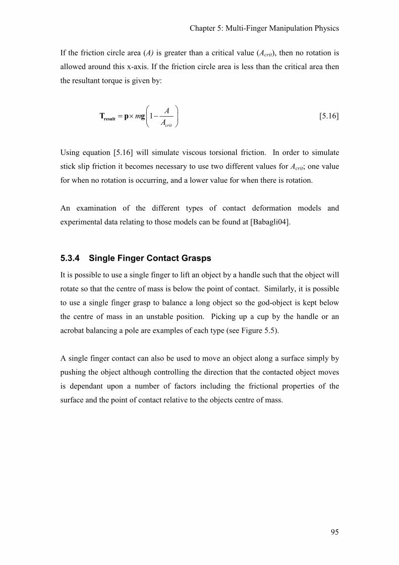
Chapter 5: Multi-Finger Manipulation Physics
95
If the friction circle area (A) is greater than a critical value (Acrit), then no rotation is
allowed around this x-axis. If the friction circle area is less than the critical area then
the resultant torque is given by:
1crit
Am
A
= × −
resultT p g [5.16]
Using equation [5.16] will simulate viscous torsional friction. In order to simulate
stick slip friction it becomes necessary to use two different values for Acrit; one value
for when no rotation is occurring, and a lower value for when there is rotation.
An examination of the different types of contact deformation models and
experimental data relating to those models can be found at [Babagli04].
5.3.4 Single Finger Contact Grasps
It is possible to use a single finger to lift an object by a handle such that the object will
rotate so that the centre of mass is below the point of contact. Similarly, it is possible
to use a single finger grasp to balance a long object so the god-object is kept below
the centre of mass in an unstable position. Picking up a cup by the handle or an
acrobat balancing a pole are examples of each type (see Figure 5.5).
A single finger contact can also be used to move an object along a surface simply by
pushing the object although controlling the direction that the contacted object moves
is dependant upon a number of factors including the frictional properties of the
surface and the point of contact relative to the objects centre of mass.

Chapter 5: Multi-Finger Manipulation Physics
96
Figure 5.5: Single finger grasps. a) A stable single finger grasp (hook) where the centre of mass is
below the point of contact. b) An unstable single finger grasp (pole balance) where the centre of mass
is above the point of contact.
5.4 Chapter Summary
This chapter has shown how it is possible to calibrate multiple, discrete haptic devices
to operate in the same virtual workspace. This is important as it is necessary that the
positions and forces are being transferred to / from the user in the correct manner
otherwise what the user will see and feel can become extremely disconnected. The
Residual Force and Torque Algorithms have also been detailed which allows the user
to grasp an object with multiple points of contacts and manipulate it in a realistic
manner. This is achieved by summing all the forces and torques that are acting upon
the object and then resolving these forces and torques to generate a new position and
orientation of the object. One feature of the Residual Torque Algorithm is that it
allows the Coriolis force to be generated when the object rotates at high speeds.
This chapter concludes with a look at two finger and single finger grasps. When more
than two points of contacts are used, it is possible to manipulate an object fully.
However, with two points of contact and no torsional friction, it is not possible to
naturally rotate the object around the axis formed between the two points of contact.
Two methods are described that allow for this rotation to be performed: using
instrumented gimbals as part of the haptic device and a simple implementation of

Chapter 5: Multi-Finger Manipulation Physics
97
torsional friction that allows for an object to rotate between the contact points due to
gravity. The different single finger grasps and manipulations are also described which
includes lifting via a handle, pole balancing and simple pushing.
98
6 Interactions Between Objects and their
Environment
In order to be able to generate a realistic, dynamic simulation in a virtual
environment, it is necessary that the virtual objects interact with their environment in
a realistic manner. This will invariably require that objects in the environment will
come into contact with other objects such as a cup placed on a shelf, a stack of boxes
sitting on the floor, or a ball bouncing off a wall. There already exists a number of
physics libraries that can be used to achieve these interactions such as the open source
Open Dynamics Engine [wwwODE07] or the commercial Havok Physics engine
[wwwHavok07] but since they were developed for use in either low update
applications (such as computer games) or high accuracy simulations where update rate
is not a concern, they may not be suitable for use in Haptic enabled environments
which require both high update rates and high accuracy.
This chapter is concerned with these types of object-object collisions, in particular
when one of the objects is being manipulated through a haptic device. The way in
which an object can be picked up and placed on a surface is investigated as well as the
means to simulate this. This chapter concludes by looking at how a manipulated
object can be used to feel the shape of another object thus allowing a volumetric
proxy to be used instead of the volumeless haptic interaction points that have
previously been described.
6.1 Types of Interaction
There are three distinct types of haptic object interactions that can occur in a haptic
environment that need to be considered:
a. An un-grasped object is in contact/collision with another un-grasped
object. (6.1.1)
b. A grasped object is in contact/collision with an unmoveable object
such as a floor or wall (6.1.2).
c. A grasped object is in contact/collision with another moveable object
(6.1.3).

Chapter 6: Interactions Between Objects and their Environment
99
An object that is currently being manipulated by a user through a haptic device will
require that the contacted object is updated at haptic update rates. Since the residual
forces need to be calculated at haptic update rates, this object is now referred to as a
haptic object.
6.1.1 Non-Haptic Object Interactions
If an object is not being directly or indirectly affected by forces from the user then it is
not necessary for the interacting objects to be updated at haptic rates. In a heavily
populated virtual environment, the majority of the object interactions will be of this
type and these objects and their interactions can be updated at the slower, visual
update rate.
6.1.2 Haptic Object with Fixed Object Interactions
The majority of haptic interactions between a grasped object will be with a fixed
object since this type of interaction will occur whenever an object is picked up or put
down on a surface. It is these types of object interactions that are further investigated
in this chapter.
6.1.3 Haptic Object with Dynamic Object Interactions
If a haptic object is in contact with another moveable object then it should be possible
to affect the contacted object with the grasped object. Similarly, if two objects are
stacked on top of each other and the bottom object is lifted, it is reasonable to expect
that the top object also moves and that the user feels as though they are lifting a mass
equivalent to both objects. However, these kinds of interaction can become
computationally expensive when more than two objects are involved as long chains of
interactions can be required and all objects in the chain will need to be updated at
haptic rates. These types of interactions have not been investigated although a
‘lumping’ algorithm could be used to simplify this, where all objects in contact are
treated as a single object.

Chapter 6: Interactions Between Objects and their Environment
100
6.2 Picking and placing objects
One of the most common ways that we interact with objects is to pick them up and put
them down onto a surface. Since it is a task that we all have great experience in, it is
necessary that this action can be simulated in as natural a manner as possible in a
virtual environment.
If we are placing a square based cup on a table it is usual that first a corner of the cup
will contact the table, quickly followed by an edge before the entire base will contact
the table. If the cup has a circular base, then the edge will make contact first before
the base.
From the above example it can be seen that the initial contact of the corner or edge
causes the cup to reduce the number of rotational degrees of freedom of the object
causing it to rotate towards the base. In order to achieve this in a haptic simulation it
is necessary to be able to determine where the objects are in contact (contact
determination) and how the objects should be constrained because of it (contact
response).
6.2.1 Contact Determination
Since determining where two complex objects are in contact is a non-trivial task only
the interaction between one complex object and one simple object has been
investigated. The simple objects were all parametric objects and included planes and
spheres which were tested against complex polygonal meshes. Where there were an
infinite number of points of contact such as when an edge was lying along the surface
of a plane only two contact points were returned, one at each end of the edge.
Similarly, when a face was fully in contact with a plane then a contact point was
returned for each corner of the face.
The methods that were developed for determining the contact points are given in
Section 7.4.

Chapter 6: Interactions Between Objects and their Environment
101
6.2.2 Contact Response
Once it has been determined where the contact is going to occur, it is necessary to be
able to apply an appropriate response to the object. Two methods for doing this were
investigated and developed: the impulse (velocity) based method and the force
(acceleration) based method.
When two rigid bodies collide the obvious solution is to apply a force to both bodies
at the point of contact. However, a force won’t be able to stop the bodies from
interpenetrating as the force acts over time to change the object’s velocity. Instead, in
order to prevent the objects from interpenetrating, their velocities must be changed
instantaneously and this is achieved by applying an impulse to the object. These
impulse methods are used in all the major open source and commercial physics
engines and more details on how these can be implemented can be found at [Baraff97]
[Hecker97].
6.2.2.1 Impulse Response Method
In nature rigid bodies never penetrate each other. When a collision occurs the
velocities of the colliding objects are changed in a discontinuous way so that the
bodies do not penetrate. This is due to an impulse being applied to the object that near
instantaneously changes its velocity.
Impulse response methods were investigated using a sphere and a plane. While the
sphere was being placed on a surface the velocity of the sphere was reflected in the
direction of the normal of the surface and some energy was lost i.e.
( )new old e=v v n [6.1]
where v is the velocity of the grasped sphere, n is the normal of the contacted surface
and e is the coefficient of restitution.
This is the equivalent of applying a force impulse to the grasped object.
Chapter 6: Interactions Between Objects and their Environment
102
In practice, using this method allowed for very hard object contact since the objects
never interpenetrated. However, it was at the expense of stability in the system i.e.
while the grasped object was being held upon a surface, the constant changes in
velocity would make the object vibrate at the update frequency. Although this
vibration was reduced by increasing the coefficient of restitution, when complex
objects were to be used, it was envisioned that this solution could be problematic.
Furthermore, due to the encouraging results of the force response methods, impulse
methods were not pursued further. Subsequent to this research, further work in the
use of impulse methods in haptic environments has been done by Barrow [Barrow06].
6.2.2.2 Force Response Method
Whereas the impulse methods guarantee that objects will not interpenetrate, the force
based methods rely upon it.
The force response method is calculated in the same way that the forces on the haptic
interaction point are calculated, i.e. the force is proportional to the depth of
penetration. Again, using a sphere and a plane, a force was applied to the sphere at
the point of contact with the plane. The force applied was proportional to the depth of
penetration of the sphere into the plane and in the direction of the plane’s normal, i.e.
d k=f n [6.2]
where n is the normal of the contacted surface, d is the depth of penetration and k is
the stiffness of the contact.
Using this method it was expected that the stability of the system would be an issue
but, due to the high frequency that the collisions and depth were calculated at, these
problems did not present themselves. In fact, for the sphere and plane contact, it was
possible to use a stiffness constant over 5 times greater than the stiffness used to
model the interaction between the haptic interaction points and the sphere. With such
a high stiffness it was not possible to notice that the objects were interpenetrating.

Chapter 6: Interactions Between Objects and their Environment
103
One of the advantages of this method is that it is already in a form compatible with the
Residual Force / Torque Algorithms used for object movement previously described
in Chapter 5. Another advantage over the impulse method is that it does not require
that the actual time of contact is calculated. The disadvantage is that since no body is
fully rigid, it is possible to push objects into each other which can cause the world to
have a slightly spongy feeling to it if large stiffnesses can not be used.
6.2.3 Rotate Down Behaviour
When placing a polygonal object held with two fingers onto a surface, first a single
corner will make contact with the surface. Using the force response method along
with the Friction Cone Algorithm and Residual Force / Torque Algorithms, by
applying the calculated force that is caused by this contact, a torque will be induced in
the object that will cause the object to rotate. While a continued downward force is
applied by the user, the object will continue to rotate around the axis formed between
the two finger contacts until an entire edge is in contact with the surface. This will
result in two contact points where forces are being applied. Further downward force
will induce a torque along the contacted edge that will try to rotate the object further.
Since this torque is now acting around an axis in the same direction as the contacted
edge and perpendicular to the axis created between the two finger contact points this
results in the object stopping rotating. In practice, whilst using the Friction Cone
Algorithm to model the finger contacts, this is not a problem since either the user will
move his fingers to aid in the rotation of the object, or a finger will slip allowing the
object to rotate. Similarly, dependant upon the friction mechanic used between the
grasped object and the surface, the object may either slip along the surface (rotate
between the finger contacts) or roll (causing the finger contacts to move relative to the
world space coordinate frame).
When the object is grasped with three or more fingers the manner in which the object
rotates will be determined solely by the residual torque that is in the object.

Chapter 6: Interactions Between Objects and their Environment
104
mg
F
mg
A
F
= axis of rotation created between the two points of contact
a) b)
mg
A
mg
A
c) d)
Figure 6.1: A 2 dimensional representation of the rotate down behaviour. For rotate down behaviour
to occur, the amount of torsional friction at the contact points must be less than the critical value thus
allowing the object to rotate freely around axis of grasp. It is assumed that the contact between the
object and the surface is frictionless. a) Shows the object being grasped at the top most corner and
being lowered on to a surface. b) When contact with the surface is made, due to the internal torques in
the object the first point of contact (A) will not be directly under the centre of mass. c) As the object is
lowered, A will slide along the surface until d) the object is at rest on the surface. If a surface with a
large frictional component is used then A will not move. In this case, the entire object will rotate
around A as the object is lowered.

Chapter 6: Interactions Between Objects and their Environment
105
6.2.4 Rotate Up Behaviour
Similar to how an object rotates when we place it on a surface, when we lift the object
it is reasonable to expect that the object will behave in a similar manner. However,
when an object is being lifted up it will only rotate if it is not being grasped with
enough force to stop it from rotating due to gravity. Provided that this is not the case,
rotate up behaviour will automatically occur due to the Residual Torque Algorithm.
= axis of rotation created between the two points of contact
mg
A
mg
A
mg
A
F
a) b) c)
mg
A mg
d) e)
Figure 6.2: A 2 dimensional representation of the rotate up behaviour. For rotate up behaviour to
occur, the amount of torsional friction at the contact points must be less than the critical value thus
allowing the object to rotate freely around axis of grasp. a) Shows the object at rest on a surface
grasped in the top right corner with an upwards force applied. b), c) As the object is lifted, the object
rotates around the grasp axis resulting in corner A moving along the surface. d), e) Once the object has
rotated so that the grasp axis is directly above the centre of mass (and corner A is directly below it) any
additional upwards motion will lift the object up from the surface.
Chapter 6: Interactions Between Objects and their Environment
106
6.3 Feeling objects with other objects
Using the force based method for object contact described above it is possible to grasp
an object and use that object to feel the surface of another object; the contact forces
between the manipulated object and the contacted object will be transferred to the user
via the haptic devices. In order to be able to achieve this it is simply necessary to be
able to determine a point of contact, the appropriate normal to use at that point and the
interpenetration depth of the two objects. Since the Residual Force / Torque
Algorithms will control how the object moves the number of contact points on the
manipulated object is arbitrary. This means that provided multiple points of contact
can be returned for the two objects in contact, the algorithms will be able to render
forces for both convex and concave objects. This has been tested successfully using a
sphere to feel complex polygon meshes as well as other parametric objects such as
cylinders and tori. However, with the appropriate normal calculations, it is possible to
use one polygonal model to feel another.
Section 7.4 shows how the appropriate normals, contact points and penetration depths
can be calculated for a number of different object interaction types.
6.3.1 Volumetric Fingers
Since it is possible to feel an object through another object it is also possible to use
complex volumetric ‘haptic fingers’ instead of simple haptic interaction points. There
are two distinct advantages to using haptic volumes instead of points to simulate the
haptic interactions. Most importantly, as the haptic volume crosses over polygon
boundaries, the direction of the applied force will naturally change direction helping
the user to feel around the object better. Secondly, although not a problem if using
the Friction Cone Algorithm, slipping through the cracks between polygon edges
becomes impossible. However, if complex polygon models are used for the haptic
volumes and they are interacting with other complex models than the processing
required to determine all the points of collisions and their respective depths and
normals may become prohibitive. In practice, simply using a sphere as the haptic
volume will give many of the benefits of using a volume with minimal impact on the
collision detection algorithms.

Chapter 6: Interactions Between Objects and their Environment
107
= Normal force applied. Normal force is
the same as for non-volumetric proxy.
= Normal force applied. Normal force is
different to with non-volumetric proxy
= Direction of motion of centre of volumetric finger.
= Desired direction of motion.
= Outline of volumetric finger
Figure 6.3: How a ‘volumetric sphere finger’ is guided around an edge. When the volumetric finger is
on an edge, the direction of force changes smoothly from one face to the next as the sphere rolls over
the edge.
Figure 6.3 shows how a sphere can be used as the haptic volume whilst moving from
one face of a cube to another. The contact normal that is used whenever the sphere is
in contact is always towards the centre of the sphere. As the sphere approaches the
edge of the cube the direction of the force changes allowing the user to feel around the
edge of the cube successfully. If a simple point were used for the interaction and no
force shading is applied, as the point crosses the edge of the cube it will fall of the
cube.
= Force applied by the surface to the proxy.
= Outline of volumetric finger
Figure 6.4: How a ‘volumetric sphere finger’ can feel a complex surface. Note the multiple forces
acting on the volumetric proxy from the multiple contact points.
Figure 6.4 shows how a complex object with multiple points of contact with one
finger can be explored. The force that the user feels is the sum of all the forces that
Chapter 6: Interactions Between Objects and their Environment
108
the haptic proxy volume is subjected to. Similarly, the sum of all the torques applied
by each contact can also be rendered to the user if the haptic hardware allows for it.
Friction between the haptic volume and the touched object can still be rendered using
the Friction Cone Algorithm without modification provided that the collision
detection algorithms return each contact point and their associated normal. When
there are multiple points of contact between the haptic volume and the object then a
friction cone will be required for each point of contact. These individual friction
cones can then be updated independently.
6.4 Chapter Summary
This chapter has described to the reader the different ways in which a virtual object
can interact with its environment. The two different methodologies that can be used
to calculate the object response due to environmental interaction (the contact
response) are described (the force based and impulse based methods) and the force
based method is expanded to show how it can be used with the Residual Force and
Torque algorithms to allow for the picking up and placing of virtual objects within an
environment. Since this means that it is possible to feel the surface that the grasped
object is being placed on, it becomes possible to use a grasped virtual object to feel
another virtual object. It is shown how this can be used to create a volumetric
“finger” for exploring the virtual world instead of the volume-less points that have
been described so far in this thesis.

109
7 Phantom3 - The Haptic Software Application
In order to test the algorithms described in previous chapters it was necessary to
create an application framework that could implement the developed algorithms. It
was desirable that the application developed would be flexible enough so that
different rendering algorithms could be easily implemented and tested as well as for
different object representations to be used. This chapter describes the design and
implementation details of the resulting application (named Phantom3) as well as the
ancillary algorithms and methods that were also developed in order to achieve this
goal. The reasons for specific development choices made are also given. The
purpose of this chapter is to provide the reader with sufficient understanding of the
software architecture so that they are able to create their own multi-finger capable
applications and / or recreate any of the algorithms and results that are presented in
this thesis.
A secondary goal of Phantom3 was to be able to provide an easy method to quickly
setup scenes with specific haptic properties. This was necessary as the system was
also to be used to conduct various perception based psychology experiments
[McKnight04] [McKnight05] as well as to be used as a proof of concept system for a
number of other application areas. These included the investigation of impossible
objects (such as a Klein bottle and a ‘TARDIS’ object (where the outer hull is smaller
than the inner volume)), inclusion of haptics into a multi-user virtual environments
[Seelig03] [Seelig04] [Jordan02], a training simulator for small animal veterinary
training and use in a virtual shopping environment where objects could be picked of
the shelves to be placed in a shopping basket.
This chapter also includes the different collision detection algorithms that were
developed and are used by Phantom3.
7.1 Application Architecture
Given that it is necessary that a haptic update rate of at least a constant 1KHz is
maintained, this required that the application has atleast two threads: a high frequency
thread for running the haptic rendering algorithms and a lower frequency thread for
Chapter 7: Phantom3 – The Haptic Software Application
110
running everything else. In order to satisfy the need for a constant update it was
decided that RTLinux (a realtime variant of Linux) would be used for the operating
system. A real time kernel process would be used to read and write to the haptic
devices whilst a user level process would be used for everything else.
7.1.1 Features and Requirements of the Phantom3 Application
The design and development of Phantom3 was led by a number of external and
desired requirements. These requirements were set by the internal goals of the ISRG
research group in the Department of Cybernetics at the University of Reading, the
EPSRC through the “Haptic cues in multi-point interactions with virtual and remote
objects” (GR/R10455/01) research project that was sponsoring the research as well as
limitation in the available hardware.
Part of the research objectives of the EPSRC project was to investigate whether it
would be possible to use haptic systems in place of real world systems in the study of
touch based perception. This requirement meant that Phantom3 would need to be able
to be used for running psychological, perception based trials with the means to read in
test data, save and output experimental results and also allow for the timing of various
event based tasks (such as the time between hitting two keys on a keyboard.) Setting
up the perception tests would also require a means of quickly creating and setting a
virtual environment with a number of different objects, each with different physical
parameters (such as size, weight, colour, whether they were fixed or moveable etc.).
The ISRG research group also wanted to investigate the use of real time Linux
(RTLinux) to see whether it was suitable for use with the available Phantom
hardware.
Three Phantom 1.5 haptic devices were required to be used together (hence the
application name, Phantom3). Due to the interface hardware that was available, the
final application had to run on a 2.4GHz, single processor machine. Considering that
each haptic device was expected to run at update rates of atleast 1KHz and the visual
rendering also had to take place on the same machine, it was a requirement that any
developed algorithms and their implementation had to be very processor efficient in

Chapter 7: Phantom3 – The Haptic Software Application
111
order to achieve the 1Khz target update speed. Since the goal of the application was
primarily for haptic rendering, it was acceptable to use simple graphics running at
about 25Hz.
Although not a requirement, it was desirable to be able to use independent models for
the haptic rendering and the visual rendering. This was to be used as part of the
perception test to see if high fidelity visual imagery could be used to compensate for
low fidelity haptic sensation.
7.1.2 General Application Architectural Design
The application design was based upon the principle that the individual objects know
everything about themselves. This object centric approach means that each object
contains the functionality required to process its setup configuration, to render itself
and to update its position and orientation based upon the residual forces in the entity.
The advantage of this architecture is that it keeps all the object specific functionality
in one place making it a simple matter to add new object types that will automatically
function within the rest of the system. This meant that rapid progress could be made
during the early stages of the project. It was also easier for a new user to understand
how each object interacts with the various systems due to the object centric nature of
the design. The other main advantage of the object centric design is that is that it is
more memory efficient and processor efficient than using a function centric approach
since there is only one object ever in existence related to that object type. The
disadvantage is that some subsystems (such as the graphical rendering and physics
systems) are spread across multiple objects and files. This makes it more difficult to
replace various systems due to their distributed nature (e.g. upgrading the rendering
system from OpenGL to DirectX would require a large amount of rework compared
with if it were a function centric architecture). Similarly, optimising specific systems
can be less effective since it is not known how similar the data is that needs to be
processed. The object centric approach is also an architecture that just does not work
in some cases, namely the collision system. By its very nature, in order to calculate
the intersection point between two collided objects, it is necessary that the collision
system knows how to test two different shapes. These types of functions can not
feasibly be added to each object type and so a central system is required.

Chapter 7: Phantom3 – The Haptic Software Application
112
Luckily, the complexity of the Phantom3 application never exceeded the limitations
of its object centric design although, towards the end of its development, it did
become necessary to use some less than ideal programming shortcuts.
7.2 The Systems and Sub-Systems of Phantom3
Figure 7.1 shows an overview of the different sub-systems that are required and how
they link together. Only the major sub-systems are shown for clarity.
Graphic System
Render Device
User Inter face Manager
Input System
Input Manager
Physics System
Collision Engine
Physics Engine
Loading System
Application Loader
Object Loader
Object Mesh Loader
Object System
Object Factory
Object Database
Entity Manager
Light Manager
Camera Manager
Haptic Device Manager
External
Files
Create and setup
the objects
Create and s etup
the render device
If Object database does not
already contain object, request
and return a new object type
Store pointer to
returned object
in the manager
Regis ter entities w ith
the physics system
Figure 7.1: Overview of the application’s sub-systems, and some of the interfaces between them. In
particular this diagram is showing the process flow for when a scene is being loaded and created.

Chapter 7: Phantom3 – The Haptic Software Application
113
7.2.1 Entities vs Objects
An entity is an individual item that appears in a scene. It may be a visible item, a light
or even a camera. An object is the template used to create the entity. The entity is a
relatively light weight structure, containing references to the object definitions as well
as the defining characteristics of the individual item such as position, orientation, and
colour. In contrast to this, the object contains the data and functionality required to
process the entity, such as storing the mesh structure and functionality for loading it
and rendering it.
A scene will contain a number of entities whereas there will only ever be a single
object of each type in existence.
7.2.2 Application
The application contains references to all the other subsystems. It is responsible for
creating, initialising and destroying all the sub-systems as well as creating and
activating the high and low frequency update threads.
7.2.3 Loading System
The loading system is comprised of two parts: the Application and Object Loader and
the Object Mesh Loader.
7.2.3.1 Application and Object Loader
The Application and Object Loader is the central point for all loading and contains the
functionality required for loading data from the external files used to setup the system
and create the scene. The application setup configuration file contains the screen
options (size and position (if not fullscreen)), the rendering options (display shadows,
render in stereo), the data directories (where the object and mesh files are located) and
the DIVE settings. The DIVE settings relate to work done to add haptics to a
Distributed Interactive Virtual Environment and this is detailed in Section 8.3.2).
Once read in, these options are then past to the appropriate systems as required in
order to create the application.

Chapter 7: Phantom3 – The Haptic Software Application
114
The secondary task of the Application Loader is to load the objects required for the
scene. All objects that make up the scene are stored in the objects.ini configuration
file. Figure 7.2 shows a scene configuration file.
//ObjectType ObjectFile
Camera Camera_01
EnvironmentMixed EnvironmentMixed_01
//EnvironmentMesh EnvironmentMesh_01
Light Light_01
GameObject Sphere_01
GameObject Mesh_01
GameObject Mesh_02
GameObject Mesh_03
Phantom Phantom_01
Phantom Phantom_02
//Phantom Phantom_03
Figure 7.2: A typical scene configuration file. The first field indicates the type of object and the
second field indicates the object file to load.
The first field indicates the type of object that is to be loaded, the second field
indicates the object file to load (located in the ObjectDir directory previously read in).
As the scene configuration file is read in, the corresponding entities are created and
then the object specific loading is passed on to the newly created object.
A typical object file is shown in Figure 7.3

Chapter 7: Phantom3 – The Haptic Software Application
115
Name=Mesh_01
Type=Object
Scale=1.0
Colour=0.7,0.0,0.0,0.25
Mesh=cube.obj
HapticMesh=cube.obj
NoRotate=True
Inputtable=True
Mass=0.5
InertiaX= 0.00000405 InertiaY= 0.00000405 InertiaZ= 0.00000405 Position=0.3,0.05,-0.5
Orientation=1,0,0,0,1,0,0,0,1
Figure 7.3: A typical object configuration file. The object type will determine what parameters are
available for this object.
Depending upon the object type, different object parameters will be useable.
The different object types and their specific parameters are described below in the
object section.
7.2.3.2 Object Mesh Loader
The Object Mesh Loader is a secondary loading system that is used specifically for
loading in 3D model formats and converting them to an application ready state. The
model loader is capable of reading in the following 3D object formats: Autodesk’s
3DS Max ASCII Scene Exporter format (.ASE), Autodesk’s Wavefront OBJ format
(formerly the Alias Wavefront OBJ format) and Autodesk’s 3DS Max format
(.MAX).
The object mesh loader also provides the functionality to create parametric objects.
These files do not exist, but are generated and created from the input parameters
specified in the object configuration file.
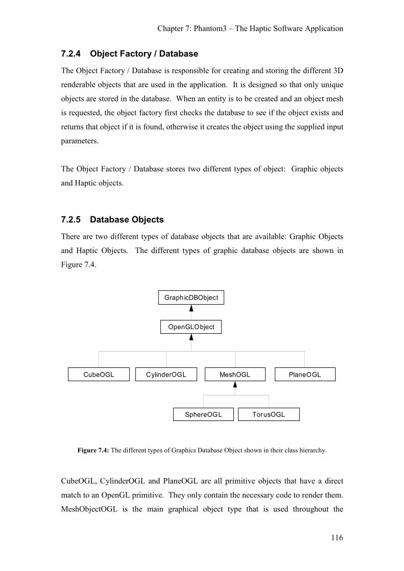
Chapter 7: Phantom3 – The Haptic Software Application
116
7.2.4 Object Factory / Database
The Object Factory / Database is responsible for creating and storing the different 3D
renderable objects that are used in the application. It is designed so that only unique
objects are stored in the database. When an entity is to be created and an object mesh
is requested, the object factory first checks the database to see if the object exists and
returns that object if it is found, otherwise it creates the object using the supplied input
parameters.
The Object Factory / Database stores two different types of object: Graphic objects
and Haptic objects.
7.2.5 Database Objects
There are two different types of database objects that are available: Graphic Objects
and Haptic Objects. The different types of graphic database objects are shown in
Figure 7.4.
GraphicDBObject
OpenGLObject
CubeOGL CylinderOGL MeshOGL PlaneOGL
SphereOGL TorusOGL
Figure 7.4: The different types of Graphics Database Object shown in their class hierarchy.
CubeOGL, CylinderOGL and PlaneOGL are all primitive objects that have a direct
match to an OpenGL primitive. They only contain the necessary code to render them.
MeshObjectOGL is the main graphical object type that is used throughout the

Chapter 7: Phantom3 – The Haptic Software Application
117
application. Due to time constraints, only the MeshObjectOGL was enhanced to
include shadow generation and rendering. Because of this, any object that was
required to cast a shadow was generated as a mesh objects (hence why SphereOGL
and TorusOGL are subclasses of the MeshObjectOGL, even though OpenGL supports
these shapes as primitives). The MeshObjectOGL type is also used for any polygon
models that are created using the Object Mesh Loader.
HapticDBObject
CubeHaptic CylinderHaptic MeshHaptic PlaneHaptic
SphereHaptic TorusHaptic
Figure 7.5: The different types of Haptic Database Object shown in their class hierarchy.
Figure 7.5 shows the different Haptic Database Objects that can be created. Each
Haptic database object includes the functionality for determining if a collision has
occurred with a haptic (Phantom) end point as well functionality for calculating the
force (both magnitude and direction) that is caused by this contact. Two methods are
given for calculating this; one that simulates frictionless contact and one that uses the
Friction Cone Algorithm. In essence, the Haptic Database Objects contains the haptic
rendering algorithms and all the data structures required for them, i.e. the MeshHaptic
object also contains the Field Directed Connection Graph for its mesh. Because of the
object centric design, if a new rendering algorithm is to be implemented, it would be
added to the Haptic Database Object.
7.2.6 Entities
A scene is comprised of many entities created from different objects. At its simplest
level, an entity contains a location (i.e. a position and orientation in the world frame).
Different entities will also contain specific data and functionality required by their
entity type. Figure 7.1 shows the different entities that are available:

Chapter 7: Phantom3 – The Haptic Software Application
118
BaseObject
EnvironmentElement GameObject
Ha pticObjectCamera
MoveableObject HapticDe vice
Re alPhantomPhantomPhantom
LightObject
Environment
EnvironmentMixedEnvironmentMesh
Figure 7.6: The different available entity types shown in their class hierarchy.
The Light Entity contains all the lighting information. This includes the colour
components (diffuse, specular and ambient), the attenuation constants, the light type
(directional or ambient) and the light direction if applicable. It also contains whether
the light should cast a shadow or not.
The Moveable Entity parent class contains all the methods required to move an entity
around. The movement of entities is controlled by keyboard and mouse events
received via the Input Manager. As such, only entities that have been registered with
the input manager will be moveable.
The Camera Entity contains the field of view, the near and far planes and the camera
frustrum used for rendering the scene.
The Haptic Entity parent class contains all the data required for enabling haptic
interaction with the haptic interaction point. It contains the haptic database object,
and the data required for haptic rendering of the object (e.g. contact points and contact
forces).

Chapter 7: Phantom3 – The Haptic Software Application
119
The Environment, EnvironmentMesh, EnvironmentMixed and EnvironmentEntity
Entities are all used to create the environment. In general use an application scene
will contain an environment and a number of game object entities. The environment
will always be static and unmoving whereas the game object entities will be dynamic
and moveable. The EnvironmentMesh is a single entity that is constructed from a
mesh. The EnvironmentMixed is a special type of entity that contains a number of
EnvironmentEntity entities. The different environment entity types are due to the
different methods of creating the environment that the Object Factory provides.
The Game Object Entity is the main dynamic entity type that is used in a scene. It is
also the main physics enabled entity. Any entity that required physically based
movement (i.e. reacting to external forces such as gravity) must be a game object
entity. It contains a reference to the Graphic Database object as well as the physical
parameters of the entity (e.g. mass, rotational inertias, centre of mass, linear and
angular velocities) as well as the data structures and functionality required for
calculating the residual forces and torques in the object
HapticDevice, RealPhantom and PhantomPhantom Entities are the entities that
represent the haptic interaction point. The HapticDevice Entity contains the interfaces
to activate, initialise, re-initialise and deactivate the haptic device as well as to read
the position of the haptic interaction point and write forces to the haptic device. Since
multiple haptic devices can be used, the Phantom Entity also stores whether this
haptic device is the main master device or the device that it is parented to. If the
device has a parent than the transformation between this device and its parent is also
calculated. The Phantom Entity also contains the transform that should be applied to
the read positions and written forces based upon the position and orientation that the
hardware is setup. The RealPhantom entity contains the specific functionality
required for using a Phantom. The PhantomPhantom entity is a special entity used for
debug purposes. It allows the application to run and function correctly without the
need for an actual haptic device. Instead, positions can be generated using the mouse
and keyboard. This entity could be further subclassed to allow for the use of a remote
device connected across a network. If a new haptic device were to be used then it
would be a subclass of the HapticDevice.

Chapter 7: Phantom3 – The Haptic Software Application
120
7.2.7 Entity Managers
For reasons of computational efficiency and code compartmentalisation, a number of
specialist entity managers were created instead of having a single global entity
manager. These managers are created when specific processing is required for entities
of that type. For instance, light entities must be setup at the beginning of each scene
before the object entities are rendered. By having separate managers for specific
functional entities, the order of processing / rendering can be better controlled whilst
also being more computationally efficient.
7.2.7.1 Game Object Entity Manager
The Game Object Entity Manager contains all the Game Object Entities loaded into
the application. It also maintains two lists of the entities; one list storing all the game
object entities that are to be updated at the haptic update frequency and a second list
for the game object entities that are to be updated at the normal update frequency.
The functionality is also provided to move the entities between the two lists. More
details on the threading / update strategy implemented can be found in Section 7.3.
7.2.7.2 Light Manager
The Light Manager maintains a list of all the light entities in the scene.
7.2.7.3 Camera Manager
The camera manager contains a list of all the cameras in the scene. Normally, only
one camera entity will exist but when stereoscopic viewing is enabled, two cameras
will exist, one for each eye’s view.
7.2.7.4 Haptic Device Manager
The Haptic Device Manager contains all the haptic device entities. It also contains the
functionality for changing the spring and damping constants used by the devices.
When multiple devices are used together a single device will be designated as the
master device that the other devices are positioned and oriented relative to. This
master device is then normally attached to the camera so that the haptic devices
always remain in the position relative to the camera’s viewpoint. The Haptic Device

Chapter 7: Phantom3 – The Haptic Software Application
121
Manager is responsible for updating the transformation matrices of each device to
ensure that this is always the case.
7.2.8 Render Device
The Render Device is responsible for the visual rendering of the scene and contains
the functionality required for rendering the entities in the scene as well as for
generating any shadows that are cast by the entities and lights.
It is possible to start the application and not use a render device. In this case, all the
objects will still be in the virtual environment but they will only be visible haptically.
Running without an active render device is equivalent to using the system with the
monitor turned off. When interfacing with the collaborative virtual environment, the
render device is replaced with the DIVE Message router. The DIVE message router is
explained in Section 8.3.2.
7.2.9 User Interface Manager
The User Interface manager is responsible for displaying all 2D text on the screen.
Text is written to the screen using 2D coordinates and the length of time that the text
should remain visible.
7.2.10 Collision Engine
The collision engine contains all the functionality for determining collisions between
multiple entities and is responsible for determining any collisions in the scene.
Entities are registered with (added to) the collision engine as being either collideable,
haptic or both. Haptic entities are tested against the haptic interaction points for
collisions and collideable entities are tested against all other collideable entities for
collisions. Every update, the collision engine first checks all registered haptic entities
for collisions with the haptic entities before determining any collisions between
individual objects. Depending upon the type of object-object collision, either a
specialist object type to object type collisions method will be used (e.g. sphere-sphere,
sphere-plane, sphere-torus, sphere-mesh) or the collision test is reduced to multiple
Chapter 7: Phantom3 – The Haptic Software Application
122
point-object tests (such as mesh-plane, mesh-mesh collisions). More details on the
actual collisions algorithms implemented are detailed in Section 7.4.
7.2.11 Physics Engine
Due to the object centric nature of the design there is no central physics engine.
Instead, all physics related code is spread between the database objects and the
entities. The haptic database object is responsible for determining the forces caused
by the interaction between the entity and the haptic end effectors, the collision system
is responsible for determining the force due to collisions between entities and the
entity is responsible for calculating its residual forces and torques and then
subsequently repositioning and reorienting itself.
7.2.12 Input Manager
The Input Manager is responsible for catching and re-routing keyboard events (key
press, key release) and mouse events (mouse button press, mouse button release,
mouse move). Once events are received then the Input Manager either calls specific
functions on various systems or passes the event onto the system to deal with. These
functions include, but are not limited to: exiting the application, disabling shadow
rendering, disabling stereoscopic rendering, modifying the stereoscopic rendering
settings, resetting all objects back to their original starting points, modifying the
spring and damper constants of the haptic devices.
Entities can also be registered with the input manager so that input events can be
dispatched to the currently active entity. These despatched events are normally used
to move the various entities around. This is useful to allow quick positioning of the
various entities in the scene (such as moving a directional light around so that the
shadows are cast in a different direction) but it is usually used as a means to control
the current camera (i.e. move around the scene).

Chapter 7: Phantom3 – The Haptic Software Application
123
7.3 Threading Strategy and Application Process Flow
Due to the need to run the haptic rendering algorithms at a high update rate and that
the application was to run on a single core CPU, a multi-process system was used
with a high frequency thread responsible for the haptic rendering, a low frequency
thread responsible for graphics and input updates and a kernel level process for
reading and writing to the Phantom hardware. Initially it was desired that all the
haptic rendering (including the calculation of the friction cones and the force/torque
resolution) would be done in hard real time (i.e. within the real time kernel) but this
was abandoned due to the difficulty in developing and debugging kernel level code.
Instead the high frequency thread was updated at the same frequency as the kernel
process. The kernel level process was solely responsible for transforming the
requested force and encoder positions to individual motor voltages and a 3D position
representing the haptic interaction point. It also had the responsibility of activating,
resetting and deactivating the Phantom hardware. A shared memory interface was
provided by the kernel process which allowed the application to read the haptic end
point position from the hardware as well as to write the calculated force vector to the
hardware.
A side effect of the haptic force calculations being in the user thread was that a jitter
of about 1ms every 1000 samples at 1kHz was introduced due to the slight delay with
swapping between the threads.
Figure 7.7 shows the different threads used, the inter-thread shared data structures and
their individual process flows.

Chapter 7: Phantom3 – The Haptic Software Application
124
Real-Time (Kernel) Thread (1kHz)Phantom Drivers
Haptic (User) Thread (≅≅≅≅1kHz) Visual (User) Thread (30Hz)
Kernel/Use r spaceDrive r Interface
X PositionY position
Z Position
X ForceY Force
Z Force
Entity Update Lists
Fast Update Entity List Slow Update Entity List
Read request force from interface.
Calculate motor voltages to achieverequested force.
Read encoder value s.
Calculate end-point position.
Write end-point position to inte rface.
Wait until next update.
Update haptic end point positions.
Calculate collisio ns betwee n haptic e ndpoints and entities in fast u pdate list.
Update physics/resolve forces for allentitie s in the fa st update l ist.
Update Positions and Orie ntations fo rentitie s in the fast update list.
Wait u ntil next u pdate.
Calculate forces that shou ld be applied bythe ha ptic devices.
Move any entitie s from the fast entity list
to the slow entity list.
Update th e keyboard and mou se inputs.
Calculate collisions b etween e ntities in th e
slow upda te list.
Resolve forces for all entities in the slow
update lis t.
Update Po sitions an d Orientations forentities in the slow update list.
Wait until next update.
Calculate forces tha t should b e applied b ythe haptic devices.
Move any entities fro m the slo w entity listto the fast entity list.
Figure 7.7: The different threads, the shared interfaces between them and their process flows. This
diagram shows the process flow after the threads have been created.
When the application is started the following process flow is used. It should be noted
that the kernel level process needs to be running before the application is loaded.
1. Load the application settings.
2. Initialise the systems as defined in the startup config file. This may include
the keyboard input system, DIVE system, graphics system.
3. Create the entities that are in the scene as defined in the scene configuration
file.
4. Create the fast and slow update threads.
5. Move the entities to the appropriate fast/slow update thread.
6. Enable the Phantom Realtime process. This process will already be running
before the application is started. Enabling it allows it to read/write to the
shared memory interface.
7. Activate the threads.
8. Wait until application exit is requested.
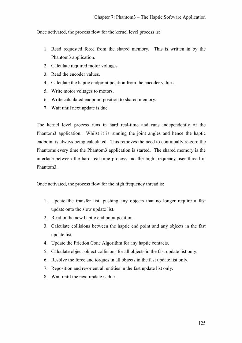
Chapter 7: Phantom3 – The Haptic Software Application
125
Once activated, the process flow for the kernel level process is:
1. Read requested force from the shared memory. This is written in by the
Phantom3 application.
2. Calculate required motor voltages.
3. Read the encoder values.
4. Calculate the haptic endpoint position from the encoder values.
5. Write motor voltages to motors.
6. Write calculated endpoint position to shared memory.
7. Wait until next update is due.
The kernel level process runs in hard real-time and runs independently of the
Phantom3 application. Whilst it is running the joint angles and hence the haptic
endpoint is always being calculated. This removes the need to continually re-zero the
Phantoms every time the Phantom3 application is started. The shared memory is the
interface between the hard real-time process and the high frequency user thread in
Phantom3.
Once activated, the process flow for the high frequency thread is:
1. Update the transfer list, pushing any objects that no longer require a fast
update onto the slow update list.
2. Read in the new haptic end point position.
3. Calculate collisions between the haptic end point and any objects in the fast
update list.
4. Update the Friction Cone Algorithm for any haptic contacts.
5. Calculate object-object collisions for all objects in the fast update list only.
6. Resolve the force and torques in all objects in the fast update list only.
7. Reposition and re-orient all entities in the fast update list only.
8. Wait until the next update is due.

Chapter 7: Phantom3 – The Haptic Software Application
126
Once activated, the process flow for the low frequency thread is:
1. Update the transfer list, pushing any objects that now require a fast update
onto the fast update list.
2. Update all non-entity systems including the input system, DIVE system and
graphics system if present.
3. Calculate object-object collisions for all objects in the slow update list only.
4. Resolve the force and torques in all objects in the fast update list only.
5. Reposition and re-orient all entities in the slow update list only.
6. Wait until the next update is due.
7.4 Collision Detection Implementation
The following collision methods were developed and implemented for determining
when the haptic interaction point had collided with an object. Calculations for the
intersection point are also given although it should be noted that in the case of the
intersection tests this calculated point is not necessarily the actual point of
intersection. To calculate the exact point of intersection it is necessary to cast a ray
from the last known position of the point to the current position and determine where
this ray intersects the objects. However, since this calculation is computationally
much more expensive than the simple solution and the positional error between the
described methods and the correct methods are negligible it was determined that the
simplified method was sufficient. This assumption holds true with the Phantom
haptic device due the high resolution of its sensors and that it is not possible to move
the device very far in one update. This small error may become an issue if a high
velocity haptic system is used with very small objects. [Eberly00] details the correct
method to calculate the intersection point for a number of parametric objects.
The methods described here are all calculated in the object’s coordinate frame (object
space). This makes it necessary to transform the point being tested from its local
coordinate frame (normally the world coordinate frame) into the object coordinate
frame. It is assumed that this has already occurred in the following explanations.

Chapter 7: Phantom3 – The Haptic Software Application
127
7.4.1 Point - Plane Intersection
Figure 7.8: Point-plane collision test.
A plane can be defined by the equation Ax + By + Cz + D = 0 or by a normal vector
(n) and a scalar distance (D) from the origin where n = [A, B, C], and D is the same
value as in the plane equation. A plane has a front and back and this is determined by
the direction of the normal. A point - plane intersection is considered to occur if the
point is behind the plane, i.e.:
D≥H ni [7.1]
If a collision has occurred then the point of intersection (p) can be defined as:
penetrationd D= −H ni [7.2]
penetrationdp = h + n [7.3]
D
n
Hb (below plane)
Ha (above plane)
(0,0,0)

Chapter 7: Phantom3 – The Haptic Software Application
128
7.4.2 Point - Sphere Intersection
Figure 7.9: Point-sphere collision test.
A sphere is defined with a radius (r) and a centre (c). A point - sphere intersection
will occur if the distance of the point to the centre is less than the radius of the circle.
i.e.:
v = H - c [7.4]
2 0r− <v vi [7.5]
If a collision has occurred then the point of intersection (p) can be defined as:
=norm
vv
v [7.6]
r normp = c + v [7.7]
7.4.3 Point - Cylinder Intersection
A cylinder is normally defined as a top radius, a base radius and a length. It is
therefore possible to create two different types of cylinder: a symmetric cylinder
where both the top and base radius are the same, and a conic cylinder where the top
and base radius are different. Although it is possible to use the same intersection test
for both types of cylinder it is more appropriate to have two separate tests due to the
c
r
Hi (inside sphere)
Ho (outside sphere)
(0,0,0)

Chapter 7: Phantom3 – The Haptic Software Application
129
comparative simplicity of the symmetric cylinder when compared to the conic
cylinder.
Figure 7.10: Point-cylinder collision test for a symmetric cylinder
A cylinder can be defined as a length l, top radius rt and base radius rb, oriented along
the y (up) axis. It is also common that the centre of the cylinder is placed at the
origin.
Collision against a cylinder is done in two steps: First, determine whether the point is
above or below the cylinder. Then calculate the radius of the cylinder at the points
relative position rr. If the horizontal distance of the point to the axis is less than the
calculated radius rr then an intersection has occurred., i.e.:
1. If the absolute ‘y’ position of the point is greater than half the cylinder
length then no collision has occurred.
2,
( . )2,
l no collisionabs y
l collision is possible
≥<
H [7.8]
2. If an intersection is possible then calculate the edge radius at the point’s
‘y’ value (rhip).
b tr rg
l
−= [7.9]
H
y axis
(0,0,0)
x axis
rt
l
rb

Chapter 7: Phantom3 – The Haptic Software Application
130
2
b tcentre
r rr
−= [7.10]
.hip centrer r g y= + H [7.11]
Note that rcentre and g can be pre-computed and do not need to be
recalculated every time.
3. If the horizontal distance of the point is less than the radius calculated in
[7.11] then an intersection has occurred.
[ ]. , 0, .x z=newH H H [7.12]
0new hipr− <H [7.13]
If the cylinder is symmetric then step 2 above is not necessary since rhip = rb = rt.
The above intersection algorithm only takes into account the body of the cylinder. If
it is necessary to collide with the top and base of the cylinder then it is necessary to
check for this separately. This can be achieved in the same manner as described for
polygon collision testing (see Section 7.4.5) but using a circle of the appropriate
radius (rt or rb) instead of the polygon edges.
The intersection point (p) can be calculated as follows:
newnorm
new
HH =
H [7.14]
[ ]0, . ,0 .hipy r= + normp H H [7.15]

Chapter 7: Phantom3 – The Haptic Software Application
131
7.4.4 Point - Torus Intersection
x
Redge
c
Rring
z
Redge Rring
c
y
x
a) b)
Figure 7.11: Point-torus collision test. a) shows a view looking from above the torus (along the y axis),
b) shows a view from the side (looking along the z axis).
A torus can be defined by a ring radius (Rring) and an edge radius (Redge) around a
centre (c). It may also be necessary to include an axis of alignment but, it is assumed
that the torus is oriented around the y (up) axis. A torus can also be thought of as a
sphere with radius Redge revolved around the up axis at a distance of Rring from the
centre.
Collision against a torus is done in two steps: First, determine how far the point is
above or below the plane of the torus. If the point is less than the edge radius then
this indicates that there is the potential for a collision. The second step is to place a
sphere with radius Redge in the direction of the point to the centre of the torus at a
distance Rring from the centre. A simple point-sphere intersection test can then be done
to determine whether an intersection has occurred, i.e.:
1. If the absolute ‘y’ position of the point is greater than the edge radius, then
no collision has occurred.
,
( . ),
r
r
R no collision abs y
R collision is possible
≥<
H [7.16]
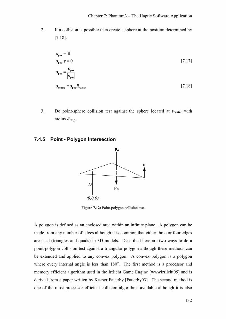
Chapter 7: Phantom3 – The Haptic Software Application
132
2. If a collision is possible then create a sphere at the position determined by
[7.18].
. 0y =
=
pos
pos
pos
pos
pos
s = H
s
ss
s
[7.17]
radiusRcentre pos
s = s [7.18]
3. Do point-sphere collision test against the sphere located at scentre with
radius Rring.
7.4.5 Point - Polygon Intersection
n
po
pn
(0,0,0)
D
Figure 7.12: Point-polygon collision test.
A polygon is defined as an enclosed area within an infinite plane. A polygon can be
made from any number of edges although it is common that either three or four edges
are used (triangles and quads) in 3D models. Described here are two ways to do a
point-polygon collision test against a triangular polygon although these methods can
be extended and applied to any convex polygon. A convex polygon is a polygon
where every internal angle is less than 180o. The first method is a processor and
memory efficient algorithm used in the Irrlicht Game Engine [wwwIrrlicht05] and is
derived from a paper written by Kasper Fauerby [Fauerby03]. The second method is
one of the most processor efficient collision algorithms available although it is also

Chapter 7: Phantom3 – The Haptic Software Application
133
one of the worst algorithms in terms of memory requirements and is based upon the
concept of voronoi regions. This method is also ideally suited for use with Face
Directed Connection Graphs (FDCGs) as it requires no data duplication (see Section
4.2.3 for information on FDCGs).
Although a polygon is made from a plane, and therefore has a front and back, it is not
possible to do a simple intersection test as described in Section 7.4.1 for the plane.
This is because in practical use a single polygon will not exist. Instead, the polygon
will be part of a mesh and it is normally necessary to determine which polygon in the
mesh was collided with. This requires a two stage approach to determining whether a
particular polygon has been collided with. Firstly, it must be determined whether the
plane that the polygon lies on has been crossed. Secondly, it must be determined
whether the plane was crossed in the enclosed area bounded by the polygon.
To determine whether the plane has been crossed it is necessary to determine the
distance that the previous position of the point (pt-1) and the current point (p
t) is from
the plane. If there is a sign change between the two distances then the plane has been
crossed, i.e.:
td D= −tp ni [7.19]
1td D− = −t-1p ni [7.20]
10,
*0,
t t collision occured
d dno collision
− <≥
[7.21]
An advantage of using this positional history is that when a collision occurs, it is
possible to determine the direction of movement i.e. if the point has entered or left the
object. This can be determined by examining the sign of the result of equation [7.19].
If the result is positive then the point has exited the object, otherwise it has entered.
Once it has been determined that the plane has been crossed, it is necessary to
determine where the intersection point (p) is and whether the intersection point is in
the area bound by the polygon. The intersection point is calculated as follows:
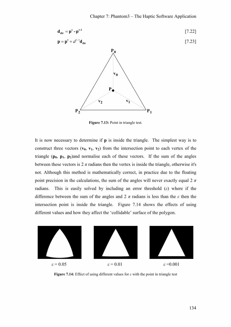
Chapter 7: Phantom3 – The Haptic Software Application
134
= t t-1
dird p - p [7.22]
1td −= +t
dirp p d [7.23]
P0
P1P2
P
v1v2
v0
Figure 7.13: Point in triangle test.
It is now necessary to determine if p is inside the triangle. The simplest way is to
construct three vectors (v0, v1, v2) from the intersection point to each vertex of the
triangle (p0, p1, p2)and normalise each of these vectors. If the sum of the angles
between these vectors is 2 π radians then the vertex is inside the triangle, otherwise it's
not. Although this method is mathematically correct, in practice due to the floating
point precision in the calculations, the sum of the angles will never exactly equal 2 π
radians. This is easily solved by including an error threshold (ε) where if the
difference between the sum of the angles and 2 π radians is less than the ε then the
intersection point is inside the triangle. Figure 7.14 shows the effects of using
different values and how they affect the ‘collidable’ surface of the polygon.
ε = 0.05 ε = 0.01 ε =0.001
Figure 7.14: Effect of using different values for ε with the point in triangle test

Chapter 7: Phantom3 – The Haptic Software Application
135
A more robust method to determine whether the point crossed the polygon is to
associate a perpendicular plane to each of the polygon’s edges. These ‘test’ planes
would be aligned along the edge so that they pass through two connecting vertices.
Given p1 and p2 are two vertices on the polygon and npoly is the normal of the
polygon, the normal (ntest) and D value (Dtest) of a perpendicular plane through p1 and
p2 can be computed as follows:
new 1 poly
p = p + n [7.24]
1 2 1
v = p - p [7.25]
2 new 1
v = p - p [7.26]
test 1 2
n = v × v [7.27]
testtest
test
nn =
n [7.28]
testD = −1 test
p ni [7.29]
Once these ‘test’ planes have been constructed the intersection point must be behind
all the test planes that surround the polygon. If this is the case, then a collision has
occurred within the polygon at the intersection point calculated previously.
7.4.6 Sphere – Object Intersections
The above intersection tests can all be modified to test whether a Sphere object
intersection has occurred. This is achieved by including the sphere’s radius into the
calculation. For a Sphere – Plane intersection test an intersection will occur if the
distance between the sphere and the plane is less than the radius of the sphere.
Similarly, if a Sphere – Sphere intersection has occurred, then the distance between
the two spheres will be less than their combined radii.
In the case of the Sphere - Polygon test it is also necessary to test whether the sphere
has intersected with the edges of the polygon. Similarly, it may also be necessary to
determine whether the sphere has intersected with the polygon’s vertices.

Chapter 7: Phantom3 – The Haptic Software Application
136
To test for intersections between the sphere and the polygon’s edges sphere – edge
intersection tests are required.
P2P1 P
P3 r
Figure 7.15: Sphere-plane collision test.
Two vectors, ve and vw are defined as:
2 1e = −v p p [7.30]
3 1w =v p - p [7.31]
By projecting vw onto ve the p can be calculated as:
w e
e e
b
=
v v
v v
i
i
[7.32]
1 eb=p p + v [7.33]
If b is between 0 and 1 then p is on the edge.
If the distance between p3 and p is less than r than a sphere edge intersection has not
occurred.
When testing the sphere against a polygon it is necessary to test for intersection with
the face, edges and vertices. If an intersection is detected then the rest of the tests can
be ignored.

Chapter 7: Phantom3 – The Haptic Software Application
137
7.4.7 Lozenges, Pebbles, and other Scaled Objects
All the above object intersection tests are described in the object’s coordinate frame
i.e. the point needs to be transformed from its native coordinate frame to the object’s
coordinate frame in order for the above methods to work. However, if the
transformation matrix between coordinate frames includes a scaling factor then it is
possible, without modification, to use the same intersection tests for capsules, pebbles
and other scaled objects. For example, a lozenge is a sphere that has been scaled
along two of its axes.
Figure 7.16: A 2D example of a scaled object. (a) shows a circle without scaling and (b) shows the
same circle scaled by 150% in the x axis and by 50% in the y axis.
In order to do the collision test with a scaled object, the points that are being tested
must first be transformed into the scaled object’s coordinate frame. This
transformation will move the point from world space to scaled object space. Since the
scaling is relative to the world space, once the point has been transformed to the
scaled object space the transformed point is no longer scaled relative to the object so
the normal collision tests can be used.
This technique is very effective when the scaled object is only tested against points
and it is this method that was used in the second psychological experiment Perceptual
Cues for Orientation in a Two Finger Haptic Grasp Task (see Section 8.3.1.2).
Unfortunately, this method is not suitable for use with complex objects such as to test
the collisions between a scaled sphere and a sphere. This is due to the fact that
(a) (b)
x axis
y axis

Chapter 7: Phantom3 – The Haptic Software Application
138
transforming one object from its coordinate frames to the other object’s coordinate
will result in one of the objects still being scaled.
7.5 Implementation Specifics
7.5.1 Integrators
In most dynamic systems that use integrators it is normally necessary to use an
advanced integrator implementation such as the Runge-Kutta (RK4) integrator. This
helps minimize the errors that are inherent in integrating a function based upon a
discrete time step and is usually achieved by over-sampling the function, i.e.
integrating over fractional time-step increments. The Phantom3 application uses
integration methods in order to convert the residual forces and torques in an object to
a new position and orientation. It was found that simple euler integration was
sufficient since the application was already running at a high time step with respect to
the input frequency. This was advantageous as the added computational time required
would have lowered the overall haptic update rate.
7.5.2 User Space vs Kernel Space
The decision to keep the haptic rendering algorithms in the non-realtime user space
instead of the real-time kernel space was made simply for ease of development since
none of the existing development tools (at time of implementation) were particularly
suited for real-time development.
7.5.3 Stick-Slip Friction Modelling
Due to floating point precision errors and the limited sensor resolution of current
haptic devices, stick-slip friction models suffer from too much stick and not enough
slip. This occurs because in one update the end point of the haptic device may not
have physically moved far enough to register a change in the sensors. This problem
can be overcome by calculating the cosine of the angle between the surface normal
and the force and comparing it to the dynamic friction threshold. The cosine of the
angle is used since this is the result of a dot product between two normalised vectors.
Chapter 7: Phantom3 – The Haptic Software Application
139
The cosine angle (θ) between the surface normal (nface) and the force (Fresp) is
calculated as follows:
resp
face
resp
cos( )=θF
nFi [7.34]
The dynamic friction threshold (DFT) is given by equation [7.35] here µd is the
coefficient of dynamic friction and ε is a small positive value.
-1
FT dD = cos(tan ( ))+µ ε [7.35]
A state change from slip to stuck will occur if:
FTcos( ) < Dθ [7.36]
7.5.4 Polygon Transitioning
Implementing the polygon-transition algorithms as described in Section 4.2.3 may
cause undesirable effects while transitioning co-planar and convex polygon
boundaries since the god-object will always be placed on the edge during polygon-
edge-polygon movement. This can be easily remedied by recursively changing the
state until the god-object does not need to be moved. This requires that the original
god-object is not updated until the proposed god-object comes to rest. By
implementing the algorithm in this way, coplanar polygons will always feel smooth;
otherwise they feel as though they have a 'sticky' ridge where the polygons are joined.
Similarly, convex polygon crossings feel more realistic instead of having sticky edges.
The disadvantage of this recursion is that the function runtime is no longer
deterministic, however, in practice the computational burden of this recursion is low.
Although recursion in real-time programming is normally considered bad practice, in
this case the god-object always converged on its resting place within three iterations
and so was not a cause of any timing problems.

Chapter 7: Phantom3 – The Haptic Software Application
140
7.6 Chapter Summary
In this chapter, the different software systems that were created in order to develop the
algorithms described in Chapters 3 to 5 have been presented. The purpose of this
chapter has been to show the user how the software was developed and structured in
order for them to be able to recreate a multi-finger enabled haptic system whilst also
highlighting any issues and workarounds that were necessary. The software structure
and systems have been detailed as well as the threading strategy that was implemented
to facilitate the high frequency requirements of haptic systems alongside the low
frequency requirements of the other systems. The process flow is also described
which explains how objects are moved between the low and fast update threads
depending upon their current requirements.
A large section has also been included to describe the different collision algorithms
used and developed. These have been included since collision detection is an
important aspect of haptic rendering. The inclusion of the intersection / collision tests
with parametric objects is of importance as it is this which allows the Friction Cone
Algorithm to be applied to parametric objects.
The chapter concludes by considering the implementation specific details. Although
this appears to be only relevant to the developed Phantom3 application, it also
contains useful information that allows the previously described algorithms to
function better in a computer simulation (i.e. a discrete time system).

141
8 Results, Case Histories and User Applications
The aim of the research described in this thesis was essentially to develop a set of
haptic rendering algorithms for multi finger contact and manipulation of rigid bodies,
i.e. to allow for the natural manipulation of virtual objects with multiple fingers.
The algorithms were designed to be generic so that they could be used to model
different surface types and materials and some psychophysical testing was done to
determine how the developed algorithms compared to the real world which is detailed
in [McKnight04] and [McKnight05].
This chapter presents some performance results and case histories that will show the
numerical robustness of the algorithms, that the developed multi-finger haptic system
is intuitive to use and that a high degree of realism can be achieved.
Videos of the multi-finger setup and application (which implements both the Friction
Cone Algorithm and the Residual Force / Torque algorithms) can be found here
[HarwinVideos]
8.1 Experimental Results
The algorithms described were implemented and tested using a dual Xeon 2.8GHz
computer running RTLinux with a Phantom 1.5 haptic interface from Sensable
Technologies. All the tests were undertaken with all surfaces having a stiffness of
500Nm and the depth of penetration of the haptic Interaction point fixed at 5mm. The
friction model shown in Figure 8.1 was used in these tests.

Chapter 8: Results, Case Histories and User Applications
142
Figure 8.1: The stiction model of friction was used for generating the experimental results.
In the first test, the haptic interface was moved across a plane. The thick line shown
in Figure 8.2 shows the path that the god-object made along the surface of the plane
and the straight lines show the direction and magnitude of the tangential force being
applied to the object by the user. The force lines are generated every 20ms. This
work follows the experiment done by Hayward [Hayward00]. In (1) and (2), the force
is in the direction of motion and is tangent to the path that is being traced. At (3), the
applied force is reduced causing the system to transitions to the stuck state causing the
god-object to stop moving. The haptic interface is then moved in a 360o clockwise
motion (whilst the god-object remains fixed) before the static friction is overcome and
motion is resumed. At (4), the motion stops and a change in direction is executed. At
(5), the same manoeuvre is completed but this time in the opposite direction.
Figure 8.2: Force direction and position whilst tracing a path over a plane.
Friction
Velocity

Chapter 8: Results, Case Histories and User Applications
143
The second set of tests shows how closely the algorithm models the friction model
that is being used. The effect that noise has on the algorithm is also tested by adding
Gaussian noise to the position of the haptic interaction point. The coefficient of static
friction µs and the coefficient of dynamic friction µd have been set to 0.7 and 0.3
respectively.
Figure 8.3: A plot of the retarding force (y-axis) against the velocity of the god-object (x-axis) with no
added gaussian noise.
It can be seen that in the absence of noise the algorithm is capable of perfectly
recreating the desired friction model (Figure 8.3). It may be expected that the
addition of noise would cause the simulation of the friction model to be affected,
however, as can be seen in Figure 8.4, the addition of noise has no adverse effect on
the algorithms ability to model the desired friction model. In fact, the addition of
noise has no effect on the simulation of the friction model. This does not mean that
the user will not perceive a difference due to the noise since any noise at the input will
move the haptic interaction point around and so this will have a corresponding effect
on the direction of the force shown to the user. Instead, it means that the underlying
simulation of the friction model is unaffected by noise and will always perfectly
recreate the desired friction model.

Chapter 8: Results, Case Histories and User Applications
144
Figure 8.4: A plot of the retarding force (y-axis) against the velocity of the god-object (x-axis) with
gaussian noise added with mean = 0 and and σ =2mm
The third test is to determine how robust the algorithm is to numerical drift. The Dahl
model and the more recent models based upon it exhibit drift when subjected to an
arbitrarily small bias force and arbitrarily small vibrations [Hayward00]. It is
important that any friction algorithm used with haptic interfaces is drift free since
small vibrations will always be present because of the discrete time nature of the
haptic controller. For this test the position of the haptic interface was fixed and
Gaussian noise was added (mean = 0 and σ = 0.2mm) to the position of the haptic
interaction point. The algorithm was then left to run over a period of approximately
three minutes.

Chapter 8: Results, Case Histories and User Applications
145
Figure 8.5: A plot of the position of the god-object and haptic interaction point against time. The
upper line (at 2.25mm) represents the position of the god-object and the lower, noisy line represents the
position of the haptic interaction point. Gaussian noise with mean = 0 and σ=0.2mm has been added to
the position of the haptic interaction point.
Figure 8.5 shows that the addition of noise does not cause the algorithm to exhibit any
apparent numerical drift over time. However, if a large amount of noise is added then
the god-object will move around a central position. This occurs since the god-object
will continually move outside of the friction circle and will constantly be repositioned.
Although the god-object will be constantly moving the algorithm is still drift free
since it will always be moving around a centralised point, i.e. the sum of the error
over time will equal 0. If the Friction Cone Algorithm was used with both the static
and dynamic friction coefficients set to 0, then the god-object movement would be
identical to the haptic interaction point’s movement. This would be the same as using
the original God-Object Algorithm of Zilles and Salisbury [Zilles95].

Chapter 8: Results, Case Histories and User Applications
146
8.2 Case Histories
Throughout the time that this research was being conducted, more than 1000 people
tried the Phantom3 demo with either two or three fingers. The demo contained 3
parts: a ball and a hoop where the user was encouraged to pick up the ball and throw it
into the hoop; a cube that would rotate freely allowing the user to pick it up, rotate it
and place it back down on the surface; 2 cubes of different sizes but the same weight.
The demo was shown to the general public at the following places:
• University Open Days, 2002 - 2006.
• The Science Museum, London, 2004.
It was shown to businesses with an interest in VR and Haptics at the following events:
• University Business Reachout Days, 2002 – 2006.
• VentureFest Business Fair, Oxford, 2004.
It was also shown at the following conferences:
• Haptic Symposium Chicago, 2004.
• EuroHaptics, Munich, 2004.
• International Conference Series on Disability, Virtual Reality and Associated
Technologies, Oxford, 2004
• International Workshop of Experts in Assistive Technology for
Neurorehabilitation, San Sebastian, 2004
• Strategic Promotion of Ageing Research Capacity Conference, Reading, 2005.
8.2.1 Case History 1
The age range of the people that tried the demo was 70 years (9 – 79 years old). In all
cases, everybody that tried to pick up a virtual object succeeded and the majority of
the participants (roughly estimated at around 85%) were able to pick up the ball and
successfully throw it into the hoop. Since the majority of the people that tried the
demo had never had any previous exposure to haptic devices yet were still able to
quickly master grasping and throwing an object this suggests that the system is both
realistic and intuitive to use. Of interest was that the younger children didn’t need any
Chapter 8: Results, Case Histories and User Applications
147
instruction on how to use the system, they just instinctively reached for the ball and
then tried to throw it in the hoop whereas some of the older people were scared of the
technology to begin with and so needed more guidance before they became adept at
grasping and manipulating the virtual objects.
8.2.2 Case History 2
The demo contained two different sized cubes with the same weight that were fixed so
that they wouldn’t rotate. Of the people that tried to pick them up approximately 50%
of the people would perceive that the smaller cube was heavier whilst the others
would not notice any difference. This aspect of the demo was designed to be similar
to the size-weight / grip span-weight illusion and the results are similar to what is
expected in the real world illusion.
8.2.3 Case History 3
Whilst the system was being demonstrated at EuroHaptics 2004, a senior haptics
researcher was interested in how we were simulating the torsional friction between the
virtual fingers and the grasped object. He was convinced that he could feel the
grasped cube rotating between his fingers and was interested in the type of actuators
we were using to present that feeling of rotational slip. Since no rotational
measurements or actuation was present, this feeling can only be put down to the
interplay between the residual force and residual torque in the object causing the
object to rotate down. Incidents like this show that the realism that was achieved by
the algorithms was high, especially since it was somebody that had many years
experience working with haptic devices that was fooled.
8.2.4 Case History 4
Since 2005, the Friction Cone Algorithm has been the main friction mechanism used
in the Chai 3D haptics library [CHAI3D] developed at Stanford University. From the
release notes:

Chapter 8: Results, Case Histories and User Applications
148
3/26/2005 - dmorris
* Lots of changes to the proxy:
* Now uses the Melder friction model for static and dynamic friction;
previously two friction models were mixed in a way that didn't
really represent static and dynamic friction.
The Chai 3D library has since been used by many research institutes including
Stanford University, Purdue University, University of Ottawa, ETH Zürich and the
Korea Institute of Science and Technology (see [CHAI3D] for a complete list).
Of particular interest is the research that has been conducted which utilises this
library’s implementation of the Friction Cone Algorithm. Ruffaldi et al [Ruffaldi06]
describe a set of standardised tests inputs and data that can be applied to any haptic
rendering algorithm in order to be able to do like for like comparisons between
different algorithms. Of significant note is their use of real world data gathered
through a force sensor. This data consists of the 3D position of the end point and the
3D force returned by the force sensor. By inputting this position data into the testbed,
the RMS force error generated using the haptic rendering algorithm can be calculated.
Their test showed that with friction disabled the RMS force error was 0.132N whereas
with a friction radius of 0.3008mm the RMS force error fell to 0.067N.
The widespread usage of the Chai 3D library (and hence the Friction Cone Algorithm)
throughout the haptics community demonstrates that the developed rendering
algorithms have been tested in numerous different applications and have now become
accepted throughout the haptics community as being fundamentally correct.
On a side note, the actual implementation of the Friction Cone Algorithm in Chai 3D
is very inefficient since it requires two cosine calculations and a tangent calculation.
These trigonometric calculations are both computationally expensive and completely
unnecessary. Furthermore, by no longer being fully vector based it is not possible for
the processor to use any SIMD instructions that it may otherwise have been able to
utilise (i.e. the compiler will not be able to optimise the code for single instruction
multiple data).

Chapter 8: Results, Case Histories and User Applications
149
8.2.5 Case History 5
After seeing and using our demo at the Haptics Symposium in Chicago, 2004,
Sensable (the makers of the Phantom Hardware) were so impressed by the ease of use
and haptic realism of the demo that they approached the department with regard to
acquiring it. This was so that they could incorporate it on their trade stand at the
conferences that they would subsequently be attending.
8.2.6 Case History 6
From Section 5.3.2 the Residual Torque Algorithm gives:
A Bω = −� [8.1]
where 1 TA RJ R T−= , 1 TB RJ R ω ω−= × , J gives the moments of inertia about a
coordinate frame at the object centre of mass with respect to the body’s
principal axes, and R is a rotation matrix to rotate this coordinate frame
into the world coordinate system.
The second term in equation [8.1] is responsible for producing the Coriolis force.
When an object has different principle inertias and where there is already a large
angular velocity around a single axis, any rotation in a different axis will create a
Coriolis force perpendicular to the desired direction of motion. In the Phantom3
application, it is possible to hold a spinning object, perform this action and briefly feel
the Coriolis force. Unfortunately, the inclusion of the second term in the calculation
is numerically unsafe and numerical errors quickly build up causing the angular
velocity in the primary axis to tend towards infinity and the simulation to shut down.
8.3 User Applications
During the development of the Phantom3 haptic engine, a number of applications
were also developed to investigate specific aspects of haptic systems. These
applications are described below. It was my responsibility to develop a system that
was flexible so that it could be adapted for a number of different applications and

Chapter 8: Results, Case Histories and User Applications
150
experiments. In all cases, I had limited input in the design of the actual applications /
experiments.
8.3.1 The Psychological Perception Experiments
One of the goals in the creation of Phantom3 was to enable perception based
psychological experiments to be run. The overall aims of these experiments were to
determine whether haptic systems and virtual environments were perceptually
equivalent to the real world and how important the inclusion of touch is in pick and
place tasks compared with just using different visual cues. It was further required to
see the effect of using single finger interaction vs. multiple finger interaction.
In order to accomplish this goal an ‘experiment manager’ was incorporated into
Phantom3 specifically for use in the various experiments. It contains all the logic
required for running a specific experiment as well as the necessary ancillary functions
such as file loading and saving and event timers. Each new experiment required that
this manager was rewritten to take into account the new experiment’s requirements.
8.3.1.1 Psychophysical Size Discrimination Using Multi-Fingered Haptic Interfaces
This psychological experiment was carried out with McKnight[McKnight04]. The
goals were two fold: 1. to determine whether there is a correlation between results
generated in psychophysical size discrimination experiments in the real world with a
similar test in the virtual, haptic enabled world, and 2. to determine if there is a benefit
to using more than two fingers in size discrimination tasks.
In order to assess the user’s ability to determine size differences a two alternative
forced-choice methodology was implemented. Participants were required to judge,
using touch alone, which of two haptically rendered spheres was the larger. Two
studies were carried out utilising a two-fingered grasp and a three-fingered grasp
condition. Spheres were chosen since it was felt that they would be more in keeping
with the natural characteristics of the grasp position. The spheres were presented
within the same time interval in two spatial locations, side by side and with a 5 cm
gap between them. One of the haptically rendered spheres (the reference or standard
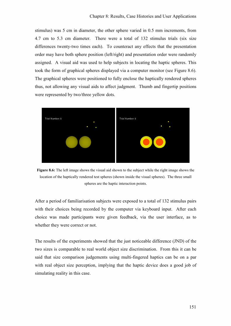
Chapter 8: Results, Case Histories and User Applications
151
stimulus) was 5 cm in diameter, the other sphere varied in 0.5 mm increments, from
4.7 cm to 5.3 cm diameter. There were a total of 132 stimulus trials (six size
differences twenty-two times each). To counteract any effects that the presentation
order may have both sphere position (left/right) and presentation order were randomly
assigned. A visual aid was used to help subjects in locating the haptic spheres. This
took the form of graphical spheres displayed via a computer monitor (see Figure 8.6).
The graphical spheres were positioned to fully enclose the haptically rendered spheres
thus, not allowing any visual aids to affect judgment. Thumb and fingertip positions
were represented by two/three yellow dots.
Figure 8.6: The left image shows the visual aid shown to the subject while the right image shows the
location of the haptically rendered test spheres (shown inside the visual spheres). The three small
spheres are the haptic interaction points.
After a period of familiarisation subjects were exposed to a total of 132 stimulus pairs
with their choices being recorded by the computer via keyboard input. After each
choice was made participants were given feedback, via the user interface, as to
whether they were correct or not.
The results of the experiments showed that the just noticeable difference (JND) of the
two sizes is comparable to real world object size discrimination. From this it can be
said that size comparison judgements using multi-fingered haptics can be on a par
with real object size perception, implying that the haptic device does a good job of
simulating reality in this case.

Chapter 8: Results, Case Histories and User Applications
152
Furthermore, the results imply that high-fidelity multi-fingered haptics using the
Friction Cone Algorithm, does a good job of simulating reality and that it can be used
in making experimental comparisons between real and virtual haptics for object
extent. The findings also indicated that using three fingers provides greater accuracy
over two fingers.
For more details about this experiment see [McKnight04].
8.3.1.2 Perceptual Cues for Orientation in a Two Finger Haptic Grasp Task
Working with McKnight[McKnight05], the goal of this psychological experiment was
to determine the effects of various cues, both visual and haptic, in a task involving
picking up an object, moving it to a specific location and then orienting it correctly.
For this experiment, Phantom3 was adapted to allow the Phantoms to be used purely
as an input device (i.e. without force feedback enabled). This required that the force
and torque being applied to the manipulated object were modified so as not to allow
large forces and torques to be generated due to the potentially large penetration depths
of the haptic interaction points. Further amendments were also made to show a more
visual representation of where objects were in collision, by changing the colour of the
region that was in contact.
This experiment required subjects to complete a pick and place task that involved
picking up a non-symmetrical object and placing it correctly in a defined position and
orientation. The task was performed both with and without haptic feedback and with
a range of visual cue combinations, including shadows and stereoscopic presentation.
The quantitative metrics of time taken and positional accuracy were used to assess
performance.
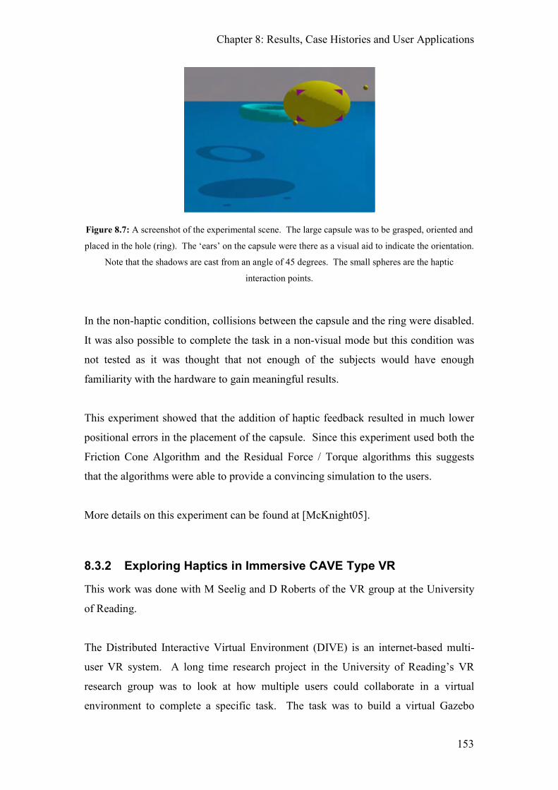
Chapter 8: Results, Case Histories and User Applications
153
Figure 8.7: A screenshot of the experimental scene. The large capsule was to be grasped, oriented and
placed in the hole (ring). The ‘ears’ on the capsule were there as a visual aid to indicate the orientation.
Note that the shadows are cast from an angle of 45 degrees. The small spheres are the haptic
interaction points.
In the non-haptic condition, collisions between the capsule and the ring were disabled.
It was also possible to complete the task in a non-visual mode but this condition was
not tested as it was thought that not enough of the subjects would have enough
familiarity with the hardware to gain meaningful results.
This experiment showed that the addition of haptic feedback resulted in much lower
positional errors in the placement of the capsule. Since this experiment used both the
Friction Cone Algorithm and the Residual Force / Torque algorithms this suggests
that the algorithms were able to provide a convincing simulation to the users.
More details on this experiment can be found at [McKnight05].
8.3.2 Exploring Haptics in Immersive CAVE Type VR
This work was done with M Seelig and D Roberts of the VR group at the University
of Reading.
The Distributed Interactive Virtual Environment (DIVE) is an internet-based multi-
user VR system. A long time research project in the University of Reading’s VR
research group was to look at how multiple users could collaborate in a virtual
environment to complete a specific task. The task was to build a virtual Gazebo

Chapter 8: Results, Case Histories and User Applications
154
where multiple users would be required to pick up, position and drill the virtual
planks. As part of this project it was desirable to see if the addition of haptics could
be used to improve the experience, speed and accuracy of this collaborative task.
Working with Roberts and Seelig, a network interface to the DIVE system was
created in Phantom3 (the DIVE Message Router) and a DIVE plugin was written to
interface between the two applications. The collaborative aspect (including the
creation of the DIVE haptic plugin) was part of an MSc undertaken by Marcel Seelig.
Full details of this research can be found in [Seelig03]. As a direct result of the initial
work that I did on the Haptic - DIVE interface further research was possible in the
area of closely coupled collaboration in VR with Haptics [Seelig04].
In order to create the interface between DIVE and Phantom3, the DIVE message
router was created. This is a bidirectional interface and is responsible for receiving
messages from the DIVE system and then distributing them to the relevant systems
for processing as well as sending messages to it when various application events
occur. The different message types that can be received by the Haptics Application
include: Initialisation, Object Creation and Deletion, Grasp and Release of an Object,
Object movement. The DIVE Message router as also used to send messages from the
Haptics Application to DIVE to indicate when an object had changed position so that
it can be updated in the Distributed Virtual Environment.
When an object was created in DIVE a haptic object would also be created inside
Phantom3. This object could then be manipulated using the haptic devices and the
objects new position and orientation would then be passed back to DIVE for
rendering. When Phantom3 was interfaced with DIVE it created no graphical output;
the graphics rendering was done by DIVE. Phantom3 was also used as the physics
engine to provide advanced physics to any non-contacted objects since there was no
inbuilt physics simulation in DIVE. This allowed objects to fall correctly and bounce
when objects were released.
8.3.3 Creating Impossible Objects
Due to the way that the Friction Cone Algorithm works and the ability to have
different graphical and haptic representations of an object, impossible objects and

Chapter 8: Results, Case Histories and User Applications
155
mathematical curiosities have been able to be constructed and manipulated in 3D.
These included a Klein bottle and a ‘TARDIS’ object.
Figure 8.8: The Klein Bottle is a single sided, four dimensional object. Note that the above image has
had a strip removed from it in order to better show its topology.
A Klein bottle is a four dimensional, single sided object. In order for it to be rendered
correctly, where the neck intersects the flask only one surface should be apparent at a
time, i.e. whilst moving down the neck the flask will not exist (allowing the user to
move ‘inside’ the bottle). In the real world this is not possible since as we move
down the neck to the flask we will physically collide with the flask but, since the
Friction Cone Algorithm uses a volumeless point of contact this does not occur and
the Klein bottle is rendered correctly.
8.3.4 The Small Creature Veterinary Prototype
Dr Sarah Baillie, (currently a veterinary surgeon and senior lecturer in veterinary
education at the Lifelong Independent Veterinary Education Centre, UK) wanted to
see whether it would be feasible to use multiple Phantoms in order to train veterinary
students to identify different problems with small creatures (such as cats and dogs).
Using Phantom3 it was possible to create a scene to simulate a cat with renal
Chapter 8: Results, Case Histories and User Applications
156
problems where the user would stroke the side of the cat, be able to feel the kidneys
underneath a skin like layer and then determine if the kidneys felt healthy (due to their
positioning and size). Because of the success of this initial prototype work a full scale
‘feline’ mixed reality simulator has since been created [Parkes09].
8.3.5 The Electromyogram (EMG) / Reach and Grasp Data
Recorder
Working alongside colleagues from the Department of Cybernetics, Phantom3 was
adapted to record finger positions and forces in a reach, grasp and place task. From a
fixed starting position, the subject was expected to reach over a high obstacle, grasp a
ball and then lift it back over the wall to place it at a desired end position. This was
repeated a number of times with the weight of the ball changing. Whilst the subject
was doing the task their muscle activity was also being measured using an EMG. The
results and conclusions of this work are still ongoing although initial results can be
found in [Louriero09]
8.3.6 The Virtual Shopping Experience
Working to create a virtual shopping experience with Barrow, a VR specialist from
Proctor and Gamble, Wann and Butler from the Psychology department at the
University of Reading, the Phantom3 application was adapted to load and display
plan-o-gram data. Plan-o-grams are used to create store shelf layouts where each
product has physical characteristics (including dimension and weight) that enables
them to be manipulated haptically. However, due to the volume of objects in a typical
shelf layout scene, these large shelve layouts could not be rendered haptically at an
acceptable update rate. Smaller plan-o-grams (with up to 10 items per shelf) were
successfully loaded and rendered both visually and haptically.
8.4 Perceptual Results
The two psychophysical perception tasks carried out by McKnight [McKnight04]
[Mcknight05] detailed in Section 8.3.1 used the Friction Cone Algorithm and
Residual Force / Torque Algorithms for friction modelling and object movement. His

Chapter 8: Results, Case Histories and User Applications
157
results from the size discrimination task [McKnight04] showed that high-fidelity
multi-fingered haptics using the Friction Cone Algorithm does a good job of
simulating reality and that it can be used in making experimental comparisons
between real and virtual haptics for object extent. The results of the task orientation
tests [Mcknight05] showed that the addition of haptic feedback resulted in much
lower positional errors in the placement of the capsule. Since these experiments used
both the Friction Cone Algorithm and the Residual Force / Torque Algorithms this
suggests that the algorithms were able to provide a convincing simulation to the users.
From this it can be concluded that even if the Friction Cone Algorithm and the
Residual Force / Torque Algorithms are not 100% accurate, their accuracy is greater
than then perceptual threshold of the users, i.e. it is accurate enough to provide a
convincing simulation.
8.5 Chapter Summary
This chapter has presented a set of subjective and objective results that shows that the
systems and algorithms developed and presented in this thesis work correctly both in
theory and in practice. The experimental results show that the Friction Cone
Algorithm is robust to noise and drift free. In fact, the addition of noise has no effect
on the algorithm’s ability to simulate the desired friction model. These results also
show that in the presence of noise, and hence small movements, the algorithms are
drift free i.e. over time the output will not change due to the build up of any error
within the system.
Due to the subjective nature of haptics, a number of case histories have been detailed
which demonstrates a number of aspects of the system as well as showing some of the
short comings. Case history 1 explains how the vast majority of people that used the
system, many of whom had never used a haptic system before, were very quickly able
to successfully complete a relatively complex task (picking up a ball and throwing it
into a hoop); this demonstrates the intuitiveness of the developed system. Case
history 3 describes how a senior haptics researcher was convinced that torsional
friction was being displayed to the user via some external actuators that weren’t
present; this demonstrates that the interplay between the Residual Force / Torque and
Friction Cone Algorithms were able to create a very realistic simulation of the real

Chapter 8: Results, Case Histories and User Applications
158
world. Case history 4 describes how the Friction Cone Algorithm has been integrated
as the main friction implementation in an open source haptics library that is used by a
large number of institutions in a wide variety of applications; this shows both the
adaptability and acceptance of the Friction Cone Algorithm amongst the wider haptics
community.
To further demonstrate the flexibility of the developed system and algorithms, a
number of the applications that were developed are described. These included various
psychophysical experiments, a veterinary simulation, the creation of impossible
objects as well the integration of haptics into other VR systems.
This chapter concludes with a summary of the results of the psychophysical
experiments run by McKnight. These show that the results achieved using the
developed haptic system are interchangeable with previous real world results and that
the addition of multi-finger haptics can improve the positional accuracy when placing
and orienting an object. This demonstrates that the use of the Friction Cone
Algorithm, the Residual Force / Torque Algorithms and the Phantom3 application are
able to provide a convincing simulation to the user since the results are comparable
with the real world.

159
9 Discussions, Further Work and Conclusions
This final chapter discusses the research undertaken and presented in this thesis
showing how they compare with previous rendering algorithms and models and how
they improve upon them. Further areas of research are also suggested which includes
how the Friction Cone Algorithm can be applied to constructive solid geometry as
well as improvements that can be made to the current system, before concluding with
a brief summary of the main features detailed in this thesis.
9.1 Discussion
The goal of the research presented in this thesis was to develop a set of algorithms
that allowed for the natural manipulation of virtual objects using multiple fingers. In
order to achieve this goal it has been necessary to develop haptic rendering methods
that simulate friction as well as methods that allow for the translation and rotation of
the grasped virtual objects. To achieve this end the Friction Cone Algorithm and
Residual Force / Torque Algorithms were developed.
Since the initial publication of the Friction Cone Algorithm in [Melder02] it has
gained popularity. Its usage has been further enhanced and adapted by Barrow
[Barrow06] as well as being the main friction algorithm used in the CHAI3D haptics
library [CHAI3D].
Features of the Friction Cone Algorithm include:
1. It is robust to noise and free of numerical drift (as shown in Section 8.1).
2. Its parameters have a simple physical interpretation.
3. It is not an accurate model of friction (and never was intended to be) but is
optimised to run in real time and to be computationally efficient (by being
entirely vector based).
4. It gives a natural set of force vectors for a multi-contacted object which
can be combined with other force vectors (such as gravity) and hence the
Residual Force / Torque Algorithms to give a natural way to estimate
position and orientation in a stable fashion.

Chapter 9: Discussions, Further Work and Conclusions
160
5. It is designed to be flexible and so allows for an arbitrarily complex
friction model to be modelled accurately (with minimal extra processing
overhead).
In order to improve the realism of the virtual world, the Friction Cone Algorithm can
be adapted to allow it to model any arbitrarily complex friction model. In its usual
implementation it only models Coulomb friction but with some simple additions it has
been shown how it can be adapted to model stick-slip friction with an additional
viscous component (see Section 4.1.1). Methods have also been given that allow the
Friction Cone Algorithm to be applied to simple, parametric objects (including
NURBS surfaces) as well as to complex polygonal meshes through the use of Face
Directed Connection Graphs. For polygonal meshes, Force Shading has been
presented that smoothes the transition between polygon edges removing the
discontinuity that would normally result.
Modelling complex friction with the Friction Cone Algorithm has a number of
advantages over previous methods. The method of simulating friction described in
[Salcudean95] is independent of the normal force applied at the contact point, i.e. the
state change to slip only occurs when the tangential force exceeds a previously
defined amount, the Friction Cone Algorithm uses the normal force to determine the
tangential force that is required. However, if it is required that the static frictional
force is independent of the normal force then this can be achieved by using a fixed
size friction cone. Similarly, since haptic devices are dependant upon their sensor
resolution, measuring near zero velocities is difficult. Since the velocity is not
required by the Friction Cone Algorithm for state transitioning, this issue is irrelevant.
Additionally, since velocity is not required the added computation required to
calculate the velocity is also not required. The Friction Cone Algorithm has also been
shown to be both drift free and robust to noise. This is of note since some of the
friction models developed have been particularly susceptible to noise and drift, in
particular the Dahl model [Dahl76] and subsequent friction models that have been
based upon it.
For polygon based models, using face directed connection graphs and their Voronoi-
like regions to determine transitions are advantageous since precision errors are no

Chapter 9: Discussions, Further Work and Conclusions
161
longer problematic. [Ruspini97] described the phenomenon of ‘falling through the
cracks’ that occurs with a volumeless point based interaction point where these cracks
are due to precision errors. Their solution is to use a proxy with a finite volume that is
larger than the cracks. Using the Voronoi planes solves this problem since transitions
are determined by the god-object’s position relative to the infinite Voronoi planes and
not the actual surface it is on. It is still possible to use the Friction Cone Algorithm
with a volume instead of a volumeless proxy and this is described in Section 6.3.
Transitions across polygon edges are also problematic in haptic rendering and
instabilities are commonly found in many implementations. These instabilities occur
when the haptic interaction point moves under an edge on a convex surface and
manifest when slight variations back and forth under the edge causes the god-object,
and hence the force, to jump abruptly between the two adjacent faces. This results in
an unnaturally rough edge or a sensation of ‘buzzing’. Using face directed connection
graphs this cannot occur. Whilst on a plane, the god-object must cross a Voronoi
plane to transition onto an edge and then the face that is closest to the haptic
interaction point becomes active. Since the Voronoi plane that must be crossed is
perpendicular to the active face, after transitioning across an edge the active face
changes and so a different Voronoi plane is used. This is illustrated in Figure 9.1
where all coefficients of friction are set to 0 (i.e. a frictionless contact is rendered).
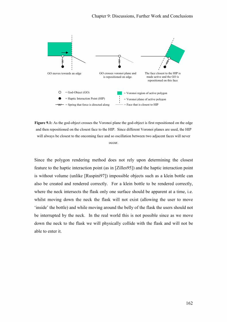
Chapter 9: Discussions, Further Work and Conclusions
162
Figure 9.1: As the god-object crosses the Voronoi plane the god-object is first repositioned on the edge
and then repositioned on the closest face to the HIP. Since different Voronoi planes are used, the HIP
will always be closest to the oncoming face and so oscillation between two adjacent faces will never
occur.
Since the polygon rendering method does not rely upon determining the closest
feature to the haptic interaction point (as in [Zilles95]) and the haptic interaction point
is without volume (unlike [Ruspini97]) impossible objects such as a klein bottle can
also be created and rendered correctly. For a klein bottle to be rendered correctly,
where the neck intersects the flask only one surface should be apparent at a time, i.e.
whilst moving down the neck the flask will not exist (allowing the user to move
‘inside’ the bottle) and while moving around the belly of the flask the users should not
be interrupted by the neck. In the real world this is not possible since as we move
down the neck to the flask we will physically collide with the flask and will not be
able to enter it.
GO moves towards an edge GO crosses voronoi plane and
is repositioned on edge.
The face closest to the HIP is made active and the GO is
repositioned on this face
= Voronoi region of active polygon
= Voronoi plane of active polygon
= God-Object (GO)
= Haptic Interaction Point (HIP)
= Spring that force is directed along = Face that is closest to HIP

Chapter 9: Discussions, Further Work and Conclusions
163
Figure 9.2: The Klein Bottle is a single sided, four dimensional object with similar properties to the
mobius strip since both of these objects posses only one side. Note that the above image has had a strip
removed from it in order to better show its topology.
With the addition of the Residual Force / Torque Algorithms, virtual objects can be
grasped, lifted, manipulated and placed. Since these algorithms work on the internal
(residual) force/torque in the object it does not matter what causes these forces and
torques, i.e. they are agnostic as to whether the force is derived from a contact with
the haptic interaction point or it is caused by some other source (such as gravity, or
contact with another object). In this way, picking up and placing an object can be
simulated in a physically correct manner simply by including any forces that are
applied through contacts between the object and the surface that it is being
placed/lifted from. When picking up or placing an object it is the interplay between
the Residual Force / Torque Algorithm and the Friction Cone Algorithm that
generates the realistic feeling associated with object placement. This is further
enhanced with the addition of torsional friction between the finger contact points that
allows the user to grip an object harder to stop it from rotating between the points of
contact.
Using the Friction Cone Algorithm and the Residual Force / Torque Algorithms allow
for rotate down/up behaviour and gravity induced drop to be modelled. Being able to
Chapter 9: Discussions, Further Work and Conclusions
164
simulate these object behaviours is important since it allows the software simulation
to accommodate deficits in the actual haptic hardware which allows for a fuller
simulation of the real world to be achieved with the limited haptic hardware.
The work done with McKnight (see Section 8.3.1) and the Case Histories given in
Section 8.2 serve to validate the intuitiveness of the developed algorithms. McKnight
showed that the haptic simulation using the Friction Cone Algorithm does a good job
of simulating reality and that it can be used in making experimental comparisons
between the real and virtual world. He also showed that haptics is important in
precision manipulation tasks and that the use of three fingers are better than two when
it comes to object size estimation. The case histories show that the use of the Friction
Cone Algorithm and the Residual Force / Torque Algorithms are intuitive to use as
the vast majority of the general public where able to quickly grasp and manipulate the
presented objects as well as successfully throw a virtual ball into a hoop. Additional
effects were also being created through the interplay of the Residual Force and
Residual Torque Algorithms that allowed for the user to experience rotational slip,
even though there was no additional actuation involved. The ability of a large
percentage of the users to experience the virtual size weight illusion also shows the
realism achieved in the simulation.
The key result that can be taken from Chapter 7 is that all the algorithms developed
are stable and robust. This is arguably the most important aspect of any developed
haptic rendering algorithms since an unstable haptic rendering algorithm will quickly
destroy the illusion of grasping a real object as it may either introduce vibrations into
the simulation, cause random force discontinuities to be presented to the user
unexpectedly, or cause the grasped objects to move erratically without the users input
(as would occur if the algorithms were not drift free).
9.2 Further Work
There are two areas where this research can be expanded into: the use of the Friction
Cone Algorithm with other 3D model representations and the use of a volumetric
proxy with the Friction Cone Algorithm. A proposal for how the Friction Cone
Algorithm can be applied to CSG trees (Constructive Solid Geometries) is presented

Chapter 9: Discussions, Further Work and Conclusions
165
in Section 9.3 based upon previous work by Raymaeker and Reeth [Raymaekers02].
The ability to use the Friction Cone Algorithm with complex NURBS surfaces is also
another area that would benefit from further investigation. The work done in the
initial investigation detailed in Section 4.2.2 has since been further expanded in
[Hong06]. With the addition of CSG and NURBS rendering, the main 3D data
representations would all be useable with the Friction Cone Algorithm.
Another potential area of research is to replace the volume-less haptic interaction
point with a volumetric representation of the user’s fingers. This would make the
system more intuitive to use, especially when tracing around the edges of an object.
The use of a volumetric proxy such as a sphere would allow the user to feel sharp (as
in non-curved) edges of an object without falling off the edge of the object as
currently happens with a volume-less proxy. Instead, as the user crosses over the
edge, the change in direction of the force being applied to the proxy allows the user to
feel around the edges. In the Phantom3 application it is already possible to feel this
affect simply by picking up an object and then using that object to feel the shape of
another object. Currently, this interaction is frictionless but it should be possible to
adapt the Friction Cone Algorithm to allow for the inclusion of friction between
multiple object contacts. This area has since been expanded by Barrow in
[Barrow06].
9.3 CSG Rendering with the Friction Cone Algorithm
Constructive Solid Geometry (CSG) is a modelling format that is used primarily in
automation procedures since many manufactured objects can be represented by a
combination of simple basic primitives. These complex objects are created by
applying one of three boolean operations on simple, mathematical objects:
intersection (∩ ), union (∪ ) and difference ( - ). Raymaekers and Van Reeth
[Raymaekers02] showed how this representation of objects could be rendered
haptically without friction. CSG is used in cases where simple geometric objects are
desired, or where mathematical accuracy is important. They have a number of unique
properties over boundary representations such as 3D polygonal meshes. One
advantage is that a CSG model guarantees that the object is “solid” or water-tight if all

Chapter 9: Discussions, Further Work and Conclusions
166
of the primitive shapes are water-tight which may be an important consideration for
some manufacturing or engineering applications. Unlike boundary representations
additional topological data is not required, and consistency checking is unnecessary to
ensure that the given boundary description specifies a valid solid object.
Another advantage that CSG has is that it is computationally simple to determine
whether an arbitrary point is inside the CSG. The point is compared against the
underlying primitives and the resulting boolean expression is evaluated. The
computational simplicity makes collision detection between a point and CSG very
quick especially when compared with an equivalent 3D polygonal mesh.
Figure 9.3: By applying boolean operators with simple primitives, complex shapes can be easily
generated [wwwCSG].
At the time that this research was started constructive solid geometries were difficult
to produce since it was only supported in high end modelling products such as

Chapter 9: Discussions, Further Work and Conclusions
167
Autodesk’s 3D Studio Max [www3DSMax09] which had a closed file format. This
meant that it was not possible to easily generate CSGs to use in haptic rendering.
However, now that a number of cheap/free game engines with readily available file
formats are available (including the Unreal Engine [wwwUnreal09], the Source
Engine [wwwSource09] and the Torque Game Engine [wwwTorque09]) this is no
longer an issue. This will likely also increase the number of CSG models that are
available and so it would be advantageous for the Friction Cone Algorithm to support
this file format. Because of this, the proposed method for rendering CSG models is
given.
The proposed haptic rendering method requires three steps:
1. Determine initial collision and set god-object.
2. Generate list of connected primitives.
3. Determine if the god-object requires moving.
Once the initial collision between the haptic interaction point and the object has
occurred, the god-object is set as per usual (i.e. at the initial point of collision). If the
collided primitive (i.e. a leaf node in the CSG tree) was not returned by the collision
detection algorithm then this must also be found. By traversing the CSG tree, a list of
all the primitives connected to this contacted node can then be created.
Once the contacted primitive and the connected primitive list have been determined
the Friction Cone Algorithm is applied until the god-object needs to be repositioned.
If the new position of the god-object no longer lies within the active confines of the
contacted primitive then a boundary transition has occurred, otherwise the god-object
is repositioned as previously calculated.
Although cubes and prisms are CSG primitives, in terms of the haptic rendering it is
advantageous to consider them as CSG trees consisting solely of planes.
9.3.1 CSG Boundary Transitions
As the god-object moves across the object’s surface its state will change depending
upon whether it is on a primitive, an edge or a corner. The object’s state determines
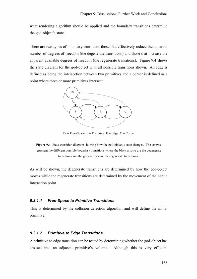
Chapter 9: Discussions, Further Work and Conclusions
168
what rendering algorithm should be applied and the boundary transitions determine
the god-object’s state.
There are two types of boundary transition; those that effectively reduce the apparent
number of degrees of freedom (the degenerate transitions) and those that increase the
apparent available degrees of freedom (the regenerate transitions). Figure 9.4 shows
the state diagram for the god-object with all possible transitions shown. An edge is
defined as being the intersection between two primitives and a corner is defined as a
point where three or more primitives intersect.
Figure 9.4: State transition diagram showing how the god-object’s state changes. The arrows
represent the different possible boundary transitions where the black arrows are the degenerate
transitions and the grey arrows are the regenerate transitions.
As will be shown, the degenerate transitions are determined by how the god-object
moves while the regenerate transitions are determined by the movement of the haptic
interaction point.
9.3.1.1 Free-Space to Primitive Transitions
This is determined by the collision detection algorithm and will define the initial
primitive.
9.3.1.2 Primitive to Edge Transitions
A primitive to edge transition can be tested by determining whether the god-object has
crossed into an adjacent primitive’s volume. Although this is very efficient
P
FS
E C
FS = Free-Space P = Primitive E = Edge C = Corner

Chapter 9: Discussions, Further Work and Conclusions
169
computationally, it is not capable of determining transitions across coplanar
boundaries. A more robust approach is to examine the vector between the original
god-object and the proposed god-object and determine if this vector intersects any of
the connected primitive’s boundaries (i.e. ray-primitive intersection test).
Unfortunately this method also has the same problem when two adjacent planes are
coplanar. When this is the case it becomes necessary to generate a ‘boundary’ plane
along the edge between the two objects. The god-object is then checked against this
boundary to determine if a transition has occurred. If a transition has occurred then it
is necessary to reposition the god-object onto the edge between the two primitives.
The method used to calculate the ‘on edge’ god-object is dependant upon whether the
originating and target primitives are flat or curved. In all cases GO1 is the original
god-object located on the active primitive, GO2 is the proposed god-object and
GOedge is the god object repositioned onto the edge. The primary primitive is the
primitive that is currently active and the secondary primitive is the primitive that is
forming the edge.
Figure 9.5: Primitive to edge transition: planar surface to curved surface.
For a planar to planar transition or a planar to curved transition (e.g. plane to sphere)
GOedge is given by the intersection of the vector GOvec = GO2 – GO1 with the
secondary primitive (see Figure 9.5).
= GO1 = GO2 = GOedge
= GOvec

Chapter 9: Discussions, Further Work and Conclusions
170
Figure 9.6: Primitive to edge transition: curved surface to planar surface. The god-objects have
been projected onto the secondary primitive.
For a curved to planar transition (e.g. sphere to plane) both GO1 and GO2 should be
projected onto the secondary primitive in the direction of the plane’s normal to give
PGO1 and PGO2. GOedge is then given by the intersection of the vector PGOvec =
PGO2 – PGO1 with the primary primitive (see Figure 9.6).
It is not possible to determine the exact position of GOedge between two curved
surfaces without using iterative methods. Instead, a good approximation can be
calculated by finding the intersection of the vector GOvec with the secondary
primitive. Due to the high update rates required by haptic rendering, human
perception and the discrete nature of the position encoder, this error should be
imperceptible.
9.3.1.3 Edge to Corner Transitions
While the god-object is on an edge it is being influenced by the two connected
primitives. An edge to corner transition will occur when the god-object intersection
vector (GOvec) intersects a third primitive. GOedge is simply defined as the
intersection between GOvec and this third primitive.
= GO1 = GO2 = PGO1 = PGO2
= Sphere’s tangential plane
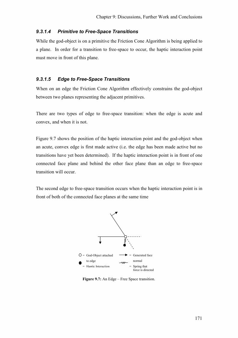
Chapter 9: Discussions, Further Work and Conclusions
171
9.3.1.4 Primitive to Free-Space Transitions
While the god-object is on a primitive the Friction Cone Algorithm is being applied to
a plane. In order for a transition to free-space to occur, the haptic interaction point
must move in front of this plane.
9.3.1.5 Edge to Free-Space Transitions
When on an edge the Friction Cone Algorithm effectively constrains the god-object
between two planes representing the adjacent primitives.
There are two types of edge to free-space transition: when the edge is acute and
convex, and when it is not.
Figure 9.7 shows the position of the haptic interaction point and the god-object when
an acute, convex edge is first made active (i.e. the edge has been made active but no
transitions have yet been determined). If the haptic interaction point is in front of one
connected face plane and behind the other face plane than an edge to free-space
transition will occur.
The second edge to free-space transition occurs when the haptic interaction point is in
front of both of the connected face planes at the same time
Figure 9.7: An Edge – Free Space transition.
= God-Object attached
to edge
= Haptic Interaction
= Generated face
normal
= Spring that force is directed along
Chapter 9: Discussions, Further Work and Conclusions
172
9.3.1.6 Corner to Free-Space Transitions
While the god-object is in a corner it will also be in contact with numerous primitives.
For each of these primitives, a tangential plane is required at the point of contact. In
order for a corner to free-space transition to occur, the haptic interaction point must be
in front of all contacted tangential planes.
9.3.1.7 Corner to Edge / Primitive Transitions
If the god-object is in a corner, the tangential planes of the connected primitives and
the connected edge vectors can be calculated if they are not already available. If the
haptic interaction point is closer to any of the connected edges/primitives than the
current corner then a corner to edge/primitive transition will occur onto the closest
edge/primitive. No matter the outcome of the transition tests, the god-object does not
need to be repositioned.
9.3.1.8 Edge to Primitive Transitions
Similar to the corner to primitive transitions, while the god-object is on an edge, the
tangential planes of the two connected primitives will be available. If the haptic
interaction point is closer to either of these planes then the current edge a transition
onto the primitive associated with the closest plane will occur. No matter the outcome
of the transition tests, the god-object does not need to be repositioned.
9.3.2 Discussion of the Proposed CSG Rendering Method
Implementing the algorithms as described may cause undesirable effects while
transitioning coplanar and convex boundaries since the god-object is always placed on
the edge during primitive-edge-primitive movement. This can be easily remedied by
recursively changing the state of the god-object (i.e. on a primitive/edge/corner) until
the god-object no longer requires repositioning. This requires that the original god-
object is not updated until the proposed god-object comes to rest. By implementing
the algorithms in this way, coplanar polygons will always feel smooth, otherwise they
feel as though they have a 'sticky' ridge where the boundaries intersect. Similarly,
convex intersections feel more realistic instead of having a 'sticky' edge. The

Chapter 9: Discussions, Further Work and Conclusions
173
disadvantage of this recursion is that the code ceases to be deterministic, however, in
practice, the computational burden of this recursion is low.
Corner to edge/primitive transitions may also appear to be computationally expensive
to compute especially as it is possible that a large number of primitives may intersect
at a single corner. However, even if this is the case, calculating the distance of the
haptic interaction point to each of the tangential planes / edges can be done in an
efficient manner using the dot product. Of more concern may be the time required to
generate all the appropriate tangential planes when the corner first becomes active. If
this delay is unacceptable then the tangential planes can be pre-calculated before
rendering starts.
9.4 Design Decisions and Features for Phantom3 Version 2
If this project were to be repeated a number of additions and amendments to the
implementation design would be made.
The main problem that was approached towards the end of the development of
Phantom3 was due to the decision to use an object-centric design approach. Instead, a
function centric approach would be used whereby all related functions would be
grouped together (e.g. all collision functions would remain in the collision engine, all
physics functionality would be in the physics engine, all rendering functionality
would remain in the render system, etc.). If an object required collisions, physics,
rendering then once it were created it would need to be registered with the appropriate
system. Internally, each system would maintain a representation of the object specific
to its functions, e.g. a physics object would represent an in game entity in the physics
system. Although more complicated to develop in the early stages of the project,
using this approach would allow greater flexibility when unexpected features /
requirements are added. This method also makes upgrading / replacing systems
easier, e.g. if a commercial rendering engine were to be used.
A full messaging system would also be desirable. Various objects would be
registered with the messaging system along with the type of events that they should
listen for. This would simplify setting up experiments where it is necessary to wait
Chapter 9: Discussions, Further Work and Conclusions
174
for certain events to occur, such as the haptic interaction points being in contact with a
particular object. In Phantom3, where this was required, direct access to the object
had to be given along with special processing code to wait for the required condition
to be achieved (i.e. two fingers on an object before the experiment could start). The
extended messaging system would also broadcast events to any listening system
whenever they occurred (such as an audio system when a collision occurred). The use
of a full messaging system would also aid in inter-thread communications.
Research has shown that the addition of audio is an important factor in our perception
of objects. As such it would be desirable to include audio in the next iteration of
Phantom3. The audio system would need to run in its own thread and would be
triggered by the aforementioned messaging system.
Since the Friction Cone Algorithm and Residual Force and Torque Algorithms are
entirely vector based this gave the option of using the advanced vector maths
functions found in most modern processors (namely SIMD (single instruction,
multiple data)). By using SIMD instructions over the basic single input, single data
instructions (vector add instead of scalar add) it is possible to achieve speed increase
of over four times in the vector processing calculations. Due to the entirely vector
nature of the developed algorithms, by converting the maths library to use SIMD it
would be possible to improve the overall performance, and hence the maximal haptic
update rate.
Further, where possible quaternion implementations of the algorithms would be used.
This is desirable since quaternions have greater numerical stability than matrices due
to the fact that they carry less redundant data than matrices (4 numbers with one
constraint for a quaternion vs. 9 numbers with many constraints). Since the product
of many orthogonal rotation matrices will become “skew” over time due to rounding
errors, as was the case when calculating the residual torques in an object, it is
necessary that the resultant matrix is “deskewed” on a regular basis. By using a
quaternion, the result will never become skewed, it will only become uniformly scaled
and it is much more computationally efficient to re-normalise a quaternion than it is to
deskew a matrix.

Chapter 9: Discussions, Further Work and Conclusions
175
9.5 Thesis Conclusion
The goal of the research presented in this thesis was to develop a set of algorithms
that allowed for the natural manipulation of virtual objects using multiple fingers. To
this end the Friction Cone Algorithm and the Residual Force / Torque Algorithms
were developed and have been described within this thesis.
Chapter 4 introduced the Friction Cone Algorithm to the reader which is a mechanism
that allows for an arbitrarily complex friction model to be simulated. It has the
following important properties:
1. It is time free as only positional information is required in its formulation.
This means that there are no issues when travelling at near zero speeds such as
when simulating stick-slip friction.
2. The output is free from numerical drift since the algorithm is time free.
3. It is robust to noise.
4. Its parameters have a simple physical interpretation.
5. It is entirely vector based and does not require any trigonometric functions in
its formulation. This makes it a very processor efficient algorithm.
6. It is designed to be flexible and so allows for an arbitrarily complex friction
model to be modelled accurately (with minimal extra processing overhead).
It has also been shown how stick-slip friction can be modelled as well as how the
Friction Cone Algorithm can be applied to various 3D object formats in order for it to
be used with complex shapes. With a simple modification to the output of the
Friction Cone Algorithm it is also possible to improve the realism of the touched
objects through force shading and bump mapping. This allows polygonal objects to
have a smooth feel to them (they would normally feel faceted when crossing across
the polygon boundaries) or to feel textured. Finally, the key advantage that the
Friction Cone Algorithm has over previous haptic rendering algorithms is that it
incorporates friction into the actual contact algorithm. This means that it is no longer
necessary to superimpose extra lateral forces to simulate friction on to the output of
the haptic rendering algorithm.
Chapter 9: Discussions, Further Work and Conclusions
176
Chapters 5 and 6 explained to the reader how multiple, discrete haptic devices could
be used together in an intuitive and realistic manner. A means to calibrate the
multiple devices to work within the same workspace was given and the Residual
Force / Torque Algorithms were presented. Together, these algorithms allow for the
natural manipulation of a virtual object under multiple contacts. The differences
between three finger, two finger and single finger grasps have also been explored and
a simple method to simulate torsional friction is presented. In a two finger grasp, this
simulated torsional friction allows for the grasped object to rotate between the fingers
due to gravity. This also allows objects to be picked up and placed onto a virtual
surface with the object reacting under all the contact forces in a realistic and natural
manner. This is due to the Residual Force / Torque Algorithms acting only upon the
residual force and torque within the object; the algorithms are agnostic to how the
force / torque was generated (i.e. it doesn’t matter if the force / torque is from a haptic
contact or a contact with another object). These algorithms also show that it is
possible to expand the Newton and Newton-Euler equations to work within the haptic
space. However, although the Residual Torque Algorithm also includes a term for
simulating the coriolis force generated within a fast spinning object, due to the
numerical inaccuracies inherent in a computer simulation, this term is best ignored.
Chapter 6 also shows how a grasped virtual object can be picked up and placed onto a
surface. In essence, this allows the user to feel another object via the grasped object.
This means that it becomes possible to create a volumetric “finger” for exploring the
virtual world instead of the volume-less points that are used in many haptic rendering
algorithms.
When the Friction Cone Algorithm, the Residual Force / Torque Algorithms and the
simulated torsional friction are used together, these algorithms combine to allow the
intuitive multi-finger manipulation of virtual objects. The experimental results show
that the Friction Cone Algorithm is robust to noise and is drift free. The results of the
psychophysical experiments run by McKnight show that the results achieved using the
developed haptic system are interchangeable with previous real world results. This
shows that the developed algorithms, within the Phantom3 application, are able to
provide a convincing, realistic simulation to the end user. To further demonstrate the
effectiveness of the system and algorithms, Chapter 8 presents a number of case
histories. Of particular note are case histories 1, 3 and 4. Demonstrating the

Chapter 9: Discussions, Further Work and Conclusions
177
intuitiveness of the system, case history 1 describes how the vast majority of people
that used the system were very quickly able to successfully pick up a virtual ball and
throw it into a virtual hoop. Case history 3 demonstrates the realisticness of the
developed system. It describes how a senior haptics researcher was convinced that
torsional friction was being displayed to the user via some external actuators even
though none were present. Case history 4 shows both the adaptability and acceptance
of the Friction Cone Algorithm amongst the wider haptics community since it
describes how the Friction Cone Algorithm has been integrated as the main friction
implementation in an open source haptics library that is used by a large number of
institutions in a wide variety of applications.
The major contributions to the field of haptics presented in this thesis are the
algorithms developed: The Friction Cone Algorithm and the Residual Force / Torque
Algorithms. Prior to the Friction Cone Algorithm, frictional forces would need to be
superimposed on top of the output of the haptic rendering algorithm. This would
often require calculating the speed of movement along the surface to determine when
to switch between stuck and slipping states. This means dealing with the inherent
problems of calculating velocity when travelling at low speeds. With the
development of the Friction Cone Algorithm this is no longer the case since a
mechanism to simulate friction is inherently designed into the actual contact
algorithm.
The Residual Force / Torque Algorithms also provide a simple way of resolving the
forces / torques within an object in a realistic manner. These algorithms are agnostic
to how the force / torque is generated and so are suitable for use whether the object is
in contact with a haptic device or with another object.
Finally, this thesis has shown how it is possible to bring together multiple, discrete
haptic devices to create a physically realistic and intuitive multi-finger haptic enabled
virtual environment.
178
10 References
Amazeen96 E. L. Amazeen, M. T. Turvey. "Weight perception and the
haptic size-weight illusion are functions of the inertia tensor,"
Journal of Experimental Psychology: Human Perception and
Performance 22, pp 213-232, 1996.
Amirabdollahian02 F. Amirabdollahian, R. C. V. Louriero, W. S. Harwin,
"Minimum Jerk Trajectory Control for Rehabilitation and
Haptic Applications", Proceedings of IEEE International
Conference on Robotics and Automation, 2002.
Armstrong-
Helouvry94
B. Armstrong-Helouvry, P. Dupont, and C. Canudas de Wit.
"A Survey of Models, Analysis Tools and Compensation
Methods for the Control of Machines with Friction,"
Automatica, 30(7):1083-1138, 1994.
Aukstakalnis92 S. Aukstakalnis, D. Blatner, "Silicon Mirage: The Art and
Science of Virtual Reality", Peach Pit Press, 1992,
ISBN 0-938151-82-7.
Babagli04 F. Barbagli, A. Frisoli, K. Salisbury, M. Bergamasco,
"Simulating human fingers: a Soft Finger Proxy Model and
Algorithm", presented at 12th International Symposium on
Haptic Interfaces for Virtual Environments and Teleoperator
Systems, Chicago, 2004.
Balaniuk00 R. Balaniuk and I. .F. Costa, "LEM - An approach for
physically based soft tissue simulation suitable for haptic
interaction", Fifth PHANTOM Users Group Workshop -
PUG00, Aspen, USA, October 2000.
Chapter 10: References
179
Balaniuk03 R. Balaniuk and K. Salisbury, "Soft-Tissue Simulation Using
the Radial Elements Method," Surgery Simulation and Soft
Tissue Modeling (IS4TM), pages 48-58, 2003.
Baraff97 D. Baraff, "An introduction to physically based modeling:
Rigid body simulation 1 - unconstrained rigid body
dynamics", SIGGRAPH Course Notes, 1997
Barrow06 A. Barrow and W. Harwin "A Dynamic Virtual Environment
for Haptic Interaction", Proceedings of Eurohaptics
Conference pp. 377-382, 2006.
Bear96 M. F. Bear, B.W. Conners, M.A. Paradiso, "Neuroscience:
Exploring the Brain", Williams & Wilkins. First Edition,
1996.
Bejczy80 A. Bejczy, K. Salisbury, "Kinematic Coupling Between
Operator and Remote Manipulator", Advances in Computer
Technology, Vol1, ASME, New York, pp197-211, 1980.
Berkelman96 P. J. Berkelman, Z. J. Butler, R. L.Hollis, "Design of a
Hemispherical Magnetic Levitation Haptic Interface Device",
ASME International Mechanical Engineering Congress and
Exposition, 1996, Atlanta Georgia.
Berkelman97 P. J. Berkelman, R. L.Hollis, "Dynamic Performance of a
Magnetic Levitation Haptic Device", SPIE International
Symposium on Intelligent Systems and Intelligent
Manufacturing, 1997, Greensburgh Pasadena.
Chapter 10: References
180
Berkelman99 P. J. Berkelman, R. L.Hollis, D. Baraff, "Interactions with a
Realtime Dynamic Environment Simulation using a
Magnetic Levitation Haptic Interface Device", IEEE
International Conference on Robotics and Automation, 1999,
Detroit Michigan.
Bertelson98 P. Bertelson, G. Aschersleben, "Automatic visual bias of
perceived auditory location", Psych. Bull. Rev. 5, pp 482-
489, 1998.
Bliss70 J. C. Bliss, M. H. Katcher, C. H. Rogers, P. R. Shephard,
"Optical-to-Tactile Image Conversion For The Blind", IEE
transactions on Man-Machine Systems 11, pp58-65, 1970.
Bolanowski88 S. J. Bolanowski Jr, G. A. Gescheider, R. T. Verrillo, C. M.
Checkosky, "Four channels mediate the mechanical aspects
of touch", Journal of the Acoustical Society of America
84(5), pp 1680-1694, 1988.
Booth03 S. Booth, F. De Angelis and T. Schmidt-Tjarksen, "The
influence of changing haptic refresh-rate on subjective user
experiences - lessons for effective touch-based applications,"
presented at Eurohaptics, Dublin, 2003..
Botvinick98 M. Botvinick, J. Cohen, "Rubber hands "feel" touch that eyes
see", Nature 391, 756, 1998.
Boulic96 R. Boulic, S. Rezzonico, D. Thalmann, "Multi-Finger
Manipulation of Virtual Objects", Proceedings of ACM
Symposium on Virtual Reality Software and Technology,
1996.

Chapter 10: References
181
Bowden50 F.P. Bowden and D. Tabor, "The Friction and Lubrication of
Solids", Clarendon Press, Oxford, 1950. 2nd edition 1954.
ISBN-10: 0198520263, ISBN-13: 9780198520269.
Bresciani05 J. P. Bresciani, M.O. Ernst, K. Drewing, G. Bouyer, V.
Maury, A. Kheddar, "Feeling what you hear: auditory signals
can modulate tactile taps perception", Journal of
Experimental Brain Research 162, pp172-180, 2005.
Brooks90 F. P. Brooks, M. Ouh-Young, J. Batter, P. J. Kilpatrick,
"Project GROPE - Haptic Displays for Scientific
Visualization", ACM Computer Graphics, Vol 24 Number 4,
1990.
Caldwell93 G. Caldwell, C. Gosney, "Enhanced Tactile Feedback (tele-
taction) using a multi-functional sensory system",
Proceedings of the IEEE International Conference on
Robotics and Automation, pp 955-960, 1993, Atlanta.
CHAI3D Chai 3D, the open source haptics project,
http://www.chai3d.org/, January 2009.
Charpentier1891 A. Charpentier, "Analyse experimentale de quelques
elements de la sensation du poids", in Archive de physiologie
normale et pathologiques 3, pp122-135, 1891.
Chial02 V. B. Chial, S. Greenish, A. Okamura, "On the Display of
Haptic Recordings for Cutting Biological Tissues", 10th
Symposium on Haptic Interfaces for Virtual Environments
and Teleoperator Systems, 2002.

Chapter 10: References
182
Cholewiak91 R. Cholewiak, A. Collins, "Sensory and physiological bases
of touch", in M. A. Heller, W. Schiff, Eds., The Psychology
of Touch. Mahwah, NJ: Erlbaum, pp. 23-60, 1991.
Cohen99 A. Cohen, E. Chen, "Six Degree-of-Freedom Haptic System
as a Desktop Prototyping System", Proceedings of ASME
International Mechanical Engineering Congress: Dynamic
Systems and Control Division (Haptic Interfaces for Virtual
Environments and Teleoperator Systems), DSC Vol 67, pp
401-402, 1999.
Connor92 C. E. Connor, K. O. Johnson, "Neural coding of tactile
texture: Comparison of spatial and temporal mechanisms for
roughness perception", The Journal of Neuroscience 12: pp.
3414-3426, 1992.
Corso02 J. J. Corso, J. Chhugani, A. Okamura, "Interactive Haptic
Rendering of Deformable Surfaces Based on the Medial Axis
Transform", Proceedings of Eurohaptics, 2002, Edinburgh.
Cutkosky86 M. R. Cutkosky, P. K. Wright, "Friction, Stability and the
Design of Robotic Fingers”, International Journal on
Robotics Research, Vol 5 No 4, pp20-37, 1986.
Cutkosky89 M. R. Cutkosky, R.D. Howe, "Human Grasp Choice and
Robotic Grasp Analysis", in S. T. Venkataraman, & T. Iberall
(Ed.), in "Dextrous Robot Hands" Springer-Verlag, 1989.
Dahl76 P.R. Dahl. "Solid Friction Damping of Mechanical
Vibrations," AIAA Journal, 14(10):1675-1682, 1976.
Chapter 10: References
183
Davis01 N. J. Davis, M. D. Morgan, A. M. Wing, "The Grasp-span
Weight Illusion", in Proceedings of Eurohaptics, 2001,
Birmingham.
Eberly00 D. Eberly, "3D Game Engine Design," Morgan Kaufmann
Publishers, 2000.
Ernst04 M. O. Ernst, J.P. Bresciani, K. Drewing, H.H. Bülthoff,
"Integration of Sensory Information Within Touch and
Across Modalities", Touch and Haptics Workshop at the
IROS 04 Conference, Sendai Japan, 2004.
Fauerby03 K. Fauerby, "Improved Collision Detection and Response",
July 2003, last seen at
http://www.peroxide.dk/papers/collision/collision.pdf, March
2005.
Faulring06 E.L. Faulring, J. E. Colgate, M. A. Peshkin, "The cobotic
hand controller: design, control and performance of a novel
haptic display", International Journal of Robotics Research,
August, 2006.
Fellner06 G. Turini, F. Ganovelli, C. Montani, "Simulating Drilling on
Tetrahedral Meshes", Eurographics 2006.
Flanagan00 J. R. Flanagan, M. A. Beltzner, "Independence of perceptual
and sensory motor predictions in the size-weight illusion",
Nat. Neurosci. 3, 737-741, 2000.
Gibson66 J. J. Gibson, "The senses considered as perceptual systems",
Houghton Mifflin Company, 1966.

Chapter 10: References
184
Gottschalk96 S. Gottschalk, M. C. Lin, and D. Manocha, "OBBTree: A
Hierarchical Structure for Rapid Interface Detection,"
presented at ACM Siggraph, 1996.
Gregory99 A. Gregory, M. Lin, S. Gottschalk, and R. Taylor, "H.
Collide: A Framework for Fast and Accurate Collision
Detection for Haptic Interactions," presented at IEEE Virtual
Reality Conference, 1999.
Haessig91 D.A. Jr Haessig and B. Friedland. "On the Modeling and
Simulation of Friction," Transactions of the ASME, 113:354-
362, 1991.
Han09 Y.M. Han, C.J. Kim and SB Choi, "A magnetorheological
fluid-based multifunctional haptic device for vehicular
instrument controls", Smart Materials and Structures 18 (1),
2009, pp1-11.
Harwin99 W. S. Harwin, S. A. Wall, "Mechatronic Design of a High
Frequency Probe for Haptic Interaction", Proceedings of the
6th International Conference on Mechatronics and Machine
Vision in Practice, pp 111-118, 1999.
HarwinVideos Videos of the haptic applications developed at the
Department of Cybernetics, University of Reading,
http://www.reading.ac.uk/isrg/isrg-haptics.asp, January 2009.
Hayward00 V. Hayward and B. Armstrong. "A New Computational
Model of Friction Applied to Haptic Rendering," pages 403-
412. Experimental Robotics VI. Springer-Verlag, lecture
notes in control and information sciences edition, 2000.

Chapter 10: References
185
Hecker97 C. Hecker, "Physics, part 3: Collision response", Game
Developers Magazine, pp 11-18, March 1997.
Helbig08 H. B. Helbig, M. O. Ernst, "Visual-haptic cue weighting is
independent of modality-specific attention", Journal of
Vision, 8(1):21, pp 1-16, January 2008.
Ho99 C. Ho, C. Basdogan, M.A. Srinivasan, "Efficient Point-Based
Rendering Techniques for Haptic Display of Virtual
Objects," Presence 8(5) Oct 1999 pp 477-491.
Hong06 X. Hong, W. S. Harwin, "Finding the point on Bezier curves
with the normal vector passing an external point",
International Journal of Modelling, Identification and Control
1(4), pp316 – 324, 2006.
HullFish96 K. C. Hullfish, "Virtual Reality Monitoring: How Real Is
Virtual Reality?", Master's Thesis, University of Washington,
Seattle, 1996.
Ino93 S. Ino, S. Shimizu, T. Odagawa, M. Sato, M. Takahashi, T.
Izumi, T. Ifukube, "A tactile display for presenting quality
materials by changing the temperature of skin surface",
Proceedings of the 2nd IEEE Workshop on Robot and
Human Communication, p220-224, 1993, Tokyo.
Ishii94 M. Ishii, M. Sato, "A 3d Spatial Interface Device Using
Tensed Strings", Presence 3, pp 81-86, 1994.
Jansson02 J. Jansson and J. Vergeest, "A Discreet Mechanics Model for
Deformable Bodies", Journal of Computer Aided Design 34,
12 (2002), pp 913-928.
Chapter 10: References
186
Johansson82 R. S. Johansson, U. Landstrom, R. Lundstrom, "Response of
Mechanoreceptive Afferent Units in the Glabrous Skin of the
Human Hand", Brain Research 244, pp17-25, 1982.
Johnson81 K. O. Johnson, G. D. Lamb, "Neural mechanisms of spatial
tactile discrimination: Neural patterns evoked by Braille-like
dot patterns in the monkey", Journal of Physiology 310:
pp.117-144, 1981.
Jordan02 J. Jordan, J. Mortensen, M. Oliveira, M. Slater, B. K. Tay, J.
Kim, M. A. Srinivasan, "Collaboration in a Mediated Haptic
Environment", Presence, 2002.
Kabelak00 Z. Kabelak, "Rendering stiff walls with PHANTOM",
Proceedings of the 2nd PHANTOM Users Research
Symposium, Zurich, 2000.
Karnopp85 D. Karnopp. "Computer Simulation of Stick-Slip Friction in
Mechanical Dynamic Systems," Transactions of the ASME,
107:100-103, 1985.
Kenshalo84 D. R. Kenshalo, "Cutaneous temperature sensitivity", in W.
W. Dawson, J. M. Enoch, Eds., "Foundations of Sensory
Science", Berlin: Springer, pp. 419-464, 1984.
Kim03 S. Kim, J. Berkley, M. Sato, "A Novel Seven Degree of
Freedom Haptic Device for Engineering Design", Virtual
Reality, 2003.
Kontarinis93 D. A. Kontarinis, R. D. Howe, "Display of High Frequency
Tactile Information to Teleoperators", SPIE Vol 2057, pp40-
50, 1993.

Chapter 10: References
187
Kontarinis95 D. A. Kontarinis, R. D. Howe, "Tactile Display of Vibratory
Information in Teleoperation and Virtual Environments",
Presence 4, pp 387-402, 1995.
Kotoku92 T. Kotoku, K. Kmoriya, K. Tanie, "A Force Display System
for Virtual Environments and its Evaluations", Proceedings
of IEEE International Workshop on Robot and Human
Communication (RoMan '92), IEEE, New York pp 246-251,
1992.
Kuchenbecker04 K. Kuchenbecker, W. Provancher, G. Niemeyer, M.
Cutkosky, "Haptic Display of Contact Location",
Proceedings of 12th International Symposium on Haptic
Interfaces for Virtual Environments and Teleoperator
Systems, pp. 66-73, 2004.
Kundu07 K. Kundu, M. Olano, "Tissue Resection using Delayed
Updates in a Tetrahedral Mesh", Proceedings of MMVR15:
Medicine Meets Virtual Reality, 2007.
Kuroda02 Y. Kuroda, M. Nakao, S. Hacker, T. Kuroda, H. Oyama, M.
Komori, T. Matsuda, T. Takahashi, "Haptic Force Feedback
with an Interaction Model between Multiple Deformable
Objects for Surgical Simulation", Proceedings of
Eurohaptics, 2002, Edinburgh.
Lakshminarayana78 K. Lakshminarayana, "Mechanics of Form Closure,"
Technical Report 78-DET-32: ASME, 1978.
Landsmeer62 J. M. F. Landsmeer, "Power Grip and Precision Handling,"
Ann Rheum Dis 21, pp 164-170, 1962.

Chapter 10: References
188
Lawrence94 D. A. Lawrence, J. D. Chapel, "Performance Trade-Offs for
Hand Controller Design", Proceedings of IEEE International
Conference on Robotics and Automation, pp3211-3216,
1994, San Diego California.
Lederman87 S. J. Lederman, R. L. Klatzky, "Hand movements: a window
into haptic object recognition", Cognitive Psychology 19:
342-368, 1987.
Lederman93 S. J. Lederman, R. L. Klatzky, "Extract Object Properties
Through Haptic Exploration", ACTA Psychologica 84, pp
29-40, 1993.
Lischinsky99 P. Lischinsky, C. Canadas-de-Wit and G. Morel, "Friction
compensation for an industrial hydraulic robot," IEEE
Control systems magazine 19(1) Feb 1999 pp25-32.
Loomis86 J. Loomis, S. J. Lederman, "Tactual perception", in K. Boff,
L. Kaufman, J. Thomas, Eds., Handbook of Human
Perception and Performance. New York: Wiley, pp. 1-41,
1986.
Louriero09 R. C. V. Louriero, "An Investigation on Robot-Based
Therapies for Whole-Arm Neurorehabilitation Following a
Stroke”, Ph. D Thesis, University of Reading, School of
Systems Engineering, Cybernetics, April 2009.
Luecke97 G. R. Luecke, Y. H. Chai, "Haptic Interaction Using a
PUMA 560 and the ISU Force Reflecting Exoskeleton
System", Proceedings of the IEEE International Conference
on Robotics and Automation, pg 106-111, 1997.

Chapter 10: References
189
Maciel04 A. Maciel, S. Sarni, O. Buchwalder, R. Boulic and D.
Thalmann, "Multi-Finger Haptic Rendering of Deformable
Objects", Proceedings of Eurographics Symposium on
Virtual Environments, 2004.
Maekawa98 H. Maekawa, J. M. Hollerbach, "Haptic Display of Object
Grasping and Manipulation in Virtual Environments",
Proceedings of IEEE International Conference on Robotics
and Automation, 1998.
Mahvash02 M. Mahvash, V. Hayward, J. Lloyd, "Haptic Rendering of
Tool Contact", Proccedings of Eurohaptics, 2002, Edinburgh.
Markenscoff90 X. Markenscoff, L. Ni, C. H. Papadimitriou, "The Geometry
of Grasping," International Journal of Robotics Research
9(1), pp 61-74, 1990.
Mas97 R. Mas, R. Boulic, D. Thalmann, "Extended grasping
behavior for autonomous human agents," First ACM
Conference on Autonomous Agents, Los Angeles, pp 494-
495, 1997.
Massie96 T. H. Massie, "Initial Haptic Explorations with the Phantom:
Virtual Touch Through Point Interaction", Thesis,
Massachusetts Institute of Technology, 1996.
McCarthy90 J.M. McCarthy, "An Introduction to Theoretical Kinematics",
pp.62-65, MIT Press, 1990.
McKnight04 S. McKnight, N. Melder, A.L. Barrow, W.S. Harwin, J.P.
Wann, "Psychophysical Size Discrimination using Multi-
fingered Haptic Interfaces", Eurohaptics, Munich, 2004.

Chapter 10: References
190
Mcknight05 S. McKnight, N. Melder, A.L. Barrow, W.S. Harwin, J.P.
Wann, "Perceptual Cues for Orientation in a Two Finger
Haptic Grasp Task",World Haptics, 2005.
McNeely93 W. A. McNeely, "Robotic Graphics: A New Approach to
Force Feedback for Virtual Reality", Proceedings of IEEE
Virtual Reality Annual International Symposium, pp. 336-
341, 1993.
Melder02 N. Melder, W. S. Harwin, "Improved Haptic Rendering for
Multi-Finger Manipulation Using Friction Cone based God-
Objects," presented at Eurohaptics, Edinburg, 2002.
Melder03 N. Melder, W. S. Harwin, and P. M. Sharkey, "Translation
and Rotation of Muti-Point Contacted Virtual Objects,"
presented at Eurohaptics, Dublin, 2003.
Melder04a N. Melder and W. S. Harwin, "Extending the Friction Cone
Algorithm for Arbitrary Polygon Based Haptic Objects,"
presented at 12th International Symposium on Haptic
Interfaces for Virtual Environments and Teleoperator
Systems, Chicago, 2004.
Melder05 N. Melder, W.S. Harwin, "Force Shading and Bump
Mapping using the Friction Cone Algorithm", World Haptics,
Pisa 2005.
Mishra89 B. Mishra, N. Silver, "Some Discussion of Static Gripping
and its Stability," IEEE Systems, Man and Cybernetics 19(4),
pp 783-796, 1989.

Chapter 10: References
191
Moller97 T. Möller, B. Trumbore, "Fast, Minimum Storage Ray-
Triangle Intersection," Journal of Graphics Tools, vol. 2, no.
1, pp. 21-28, 1997.
Montana91 D. J. Montana, "The Condition for Contact Grasp Stability”,
proceedings of the IEEE International Conference on
Robotics and Automation, 1991.
Moody01 W. Moody, R. Morgan, P. Dillon, C. Baber, A. Wing,
"Factors Underlying Fabric Perception", Proceedings of
Eurohaptics, 2001, Birmingham UK.
Morgenbesser95 H. B. Morgenbesser, "Force Shading for Haptic Shape
Perception in Haptic Virtual Environments," MIT, September
1995.
Morgenbesser96 H. B. Morgenbesser and M. A. Srinivasan, "Force shading
for haptic shape perception," presented at ASME Dynamic
Systems and Control Division, 1996.
Murayama04 J. Murayama, L. Bougrila, YL. Luo, K. Akahane, S.
Hasegawa1, B. Hirsbrunner, M. Sato, "SPIDAR G&G: A
Two-Handed Haptic Interface for Bimanual VR Interaction",
in Proceedings of Eurohaptics, 2004, Munich.
Napier56 J. R. Napier, "The Prehensile Movements of the Human
Hand," Journal of Bone Joint Surgery 38-B, pp 902-913,
1956.
Nguyen89 V-D. Nguyen, "Constructing Stable Grasps," International
Journal of Robotics Research 8(1), pp 27-37, 1989.

Chapter 10: References
192
Noh09 K. W. Noh, Y.M. Han and SB Choi, "Haptic cue device for
accelerator pedal using magnetorheological (MR) fluids",
Proc SPIE 7288, 2009.
Otaduy04 M. A. Otaduy, M. C. Lin, "A perceptually-inspired force
model for haptic texture rendering," in Proc.1st Symposium
on Applied perception in graphics and visualization, pp 123-
126, 2004.
Pan05 P. Pan, K.M. Lynch, M.A. Peshkin, J.E. Colgate, "Human
Interaction with Passive Assistive Robots", IEEE 9th
International Conference on Rehabilitation Robotics, June
2005.
Parkes09 R. Parkes, N. Forrest, S. Baillie, "A Mixed Reality Simulator
for Feline Abdominal Palpation Training in Veterinary
Medicine", Studies in Health Technology and Informatics
142: pp244-6, 2009.
Patoglu05 V. Patoglu and R. Gillespie, "A Closest Point Algorithm for
Parametric Surfaces with Global Uniform Asymptotic
Stability", Proceedings of 1st Joint Eurohaptics Conference
and Symposium on Haptic Interfaces for Virtual
Environments and Teleoperator Systems, pp348-355, Pisa,
2005.
Penfield37 W. Penfield and E. Boldrey, "Somatic Motor and Sensory
Representation in the Cerebral Cortex of Man as Studied by
Electrical Stimulation", Brain 60, pp 389-443, 1937.

Chapter 10: References
193
Phillips90 J. R. Phillips, R. S. Johansson, K. D. Johnson,
"Representation of braille characters in human nerve fibres",
Experimental Brain Research 81: pp589-592, 1990.
Phong75 B. T. Phong, "Illumination for Computer Generated
Pictures," Communications of the ACM, vol. 18(6), pp. 311-
317, 1975.
Prisco98 G. M. Prisco, C. A. Avizzano, M. Calcara, S. Ciancio, S.
Pinna, M. Bergamasco, "A Virtual Environment with Haptic
Feedback for the Treatment of Motor Dexterity Disabilities",
Proceedings of IEEE International Conference on Robotics
and Automation, 1998.
Raymaekers02 C. Raymaekers and F. Van Reeth, "Algorithms for Haptic
Rendering of CSG Trees", Eurohaptics, 2002, Edinburgh.
Raymaekers03 C. Raymaekers, K. Coninx, "Improving haptic rendering of
complex scenes using spatial partitioning", In Proceedings of
Eurohaptics, pp 193-205, Dublin, 2003.
Richards02 C. Richards and M.R. Cutkosky, "Friction modeling and
display in haptic applications involving user performance,"
Proceedings of the 2002 IEEE International Conference on
Robotics and Automation May 2002 pp605-611.
Rock64 I. Rock, J. Victor, "Vision and Touch: An Experimentally
Created Conflict between the Two Senses," in Science 7, pp
594-596, February 1964.
Chapter 10: References
194
Ruffaldi06 E. Ruffaldi, D. Morris, T. Edmunds, F. Barbagli, D.K. Pai,
"Standardized Evaluation of Haptic Rendering Systems",
Proceedings of the Symposium on Haptic Interfaces for
Virtual Environment and Teleoperator Systems, 2006.
Ruspini97 D. C. Ruspini, K. Kolarov, and O. Khatib, "The Haptic
Display of Complex Environments," presented at Siggraph,
Los Angeles, 1997.
Russell04 D. Russell, "Haptic NURBS Rendering using Friction
Cones", Symposium for Cybernetics Annual Research
Projects, 2004, pp405-409.
Salcudean95 S. E. Salcudean and T. D. Vaar, "On the Emulation of Stiff
Walls and Static Friction with a Magnetically Levitated
Input/Output Device," presented at ASME Haptic Interfaces
for Virtual Environments and Teleoperator Systems,
Dynamic Systems and Control, 1995.
Salcudean97 S. E. Salcudean, N. R. Parker, "6-DOF Desk-top Voice-Coil
Joystick", ASME International Mechanical Engineering
Congress and Exposition (Winter Annual Meeting), 1997,
Dallas Texas.
Salisbury82 J. K. Salisbury, "Kinematic and Force Analysis of
Articulated Hands”, Ph. D Thesis, Stanford University,
Department of Mechanical Engineering, May 1982.
Schinner93 A. Schinner, Features and Voronoi regions, last known web
address:
http://www.cs.brown.edu/courses/cs252/misc/resources/lectu
res/pdf/notes09.pdf, March 1993.

Chapter 10: References
195
Scilingo00 E. P. Scilingo, A. Bicchi, D. De Rossi, A. Scotto, "A
magnetorheological fluid as a haptic display to replicate
perceived biological tissues compliance", 1st Annual
International IEEE-EMBS Special Topic Conference on
Microtechnologies in Medicine & Biology
October 12-14,2000, pp 229-233
Seelig03 M. Seelig, "Implementation of Mechanisms to Enhance
Collaboration in Multi-User Virtual Environments - Haptic
Interfaces", MSc Thesis, University of Reading, 2003.
Seelig04 M. Seelig, W. Harwin, D. Roberts, O.Otto and R. Wolff, "A
Haptic Interface for Linked Immersive and Desktop
Displays: Maintaining Sufficient Frame Rate for Haptic
Rendering", ISCA PDCS 2004, pp478-483.
Tachi94 S. Tachi, T. Maeda, R. Hirata, H. Hashino, "A Construction
Method of Virtual Haptic Space", Proceedings of
International Conference on Artificial Reality and
Telepresence, pp. 131-138, 1994.
Thompson99 T. V. Thompson, and E. Cohen, "Direct haptic rendering of
complex trimmed NURBS models," Proc. ASME Dynamic
Systems and Control Division, Nashville, TN, 1999.
VanderLinde02 R.Q. Van der Linde, P. Lammertse, E. Frederiksen, B. Ruiter,
"The Haptic Master, A new high-performance haptic
interface", Eurohaptics, 2002, Edinburgh.
Walairacht01 S. Walairacht, M. Ishii, Y. Koike, M. Sato, "Two-Handed
Multi-Finger String Based Haptic Interface Device", IEICE
TRANS. INF. & SYST., Vol E84-D, NO. 3, 2001.

Chapter 10: References
196
Wall00 S. A. Wall, "An Investigation of Temporal and Spatial
Limitations of Haptic Devices", PhD Thesis, University of
Reading, 2000.
Wall00b S.A. Wall, W.S. Harwin "Effect of Physical Bandwidth on
Perception of Virtual Gratings", Symposium on Haptic
Interfaces for Virtual Environments and Teleoperators, 2000,
pp. 1033-1039.
Wang05 N. Wang, Y. Zhang, C. Liang, "Study on reflection ray-
tracing method of UTD based on NURBS modelling", in
Microwave Conference Proceedings, 2005.
www3DSMax09 Autodesk 3D Studio Max, last seen at
http://usa.autodesk.com/adsk/servlet/pc/index?siteID=123112
&id=13567410, December 2009.
wwwCForce05 Immersion Grounded glove system, last seen at
http://www.immersion.com/3d/products/cyber_force.php,
March 2005.
wwwCGrasp05 Immersion Cyber Grasp glove, last seen at
http://www.immersion.com/3d/products/cyber_grasp.php,
March 2005.
wwwCSG CSG tree, last seen at
http://en.wikipedia.org/wiki/File:Csg_tree.png,
November 2009.
wwwFCS05 FCS control Systems Website, last seen at
http://www.fcs-cs.com/robotics, March 2005.

Chapter 10: References
197
wwwFD05 Force Dimension Website, last seen at
http://www.forcedimension.com, March 2005.
wwwHangOn07 Wikipedia Entry for SEGA Hang-on, last seen at
http://en.wikipedia.org/wiki/Hang-On, June 2007.
wwwHavok07 Havok Physics, last seen at
http://www.havok.com/, August 2007.
wwwHomunc09 The Sensory Homunculous, last seen at
http://dm.ncl.ac.uk/blog/wp-
content/uploads/2009/01/homunculus1.jpg, October 2009.
wwwiFeel05 Logitech iFeel Haptic Mouse, last seen at
http://www.deafgamers.com/ifeelmm.htm, March 2005
wwwISRG04 Haptic Interfaces at the University of Reading, Interactive
Systems Research Group, last seen at
http://www.isrg.rdg.ac.uk/haptics, 2004.
wwwLapara05 Reachin Laparascopic Trainer, last seen at
http://www.reachin.se/products/reachinlaparoscopictrainer/,
March 2005.
wwwLIMS10 The Laboratory for Intelligent Mechanical Systems at
Northwestern University, Last seen at,
http://lims.mech.northwestern.edu/, October 2010.
wwwLogitech07 Logitech, last seen at http://www.logitech.com, June 2007.
Chapter 10: References
198
wwwMagLev05 Magnetic Levitation Haptic Interfaces at Carnegie Mellon
University, last seen at
http://www-2.cs.cmu.edu/afs/cs.cmu.edu/project/msl/www/h
aptic/haptic_desc.html, March 2005.
wwwMPD05 MPD Technologies Haptic Device Webpage, last seen at
http://www.mpbtechnologies.ca/mpbt/haptics/hand_controlle
rs/haptics_index.html, 2004.
wwwNovint07 NOVINT, last seen at http://www.novint.com, June 2007.
wwwODE07 Open Dynamics Engine, last seen at http://ode.org/, August
2007.
wwwPERCRO05 The PERCRO laboratory, last seen at,
http://www.percro.org/, March 2005.
wwwProvancher07 Experiment Protocol and Details, last seen at
http://bdml.stanford.edu/twiki/bin/view/Haptics/ProposedExp
erimentProtocalAndDetails, June 2007.
wwwSensable05 Sensable Technologies Website, last seen at
http://www.sensable.com, March 2005.
wwwSkin07 Cross section of the skin, last seen at
http://academic.uofs.edu/faculty/cannon/kidsjudge/kj04/celiia
2_files/skinreceptors.jpg, October 2007.
wwwSolid05 The SOLID collision library, last seen at
http://www.dtecta.com/, March 2005.
Chapter 10: References
199
wwwSource09 The Source Engine, last seen at
http://source.valvesoftware.com/, December 2009.
wwwSPIDAR05 The SPIDAR 8, last seen at
http://sklab-www.pi.titech.ac.jp/~somsak/spidar8.html,
March 2005.
wwwTorque09 The Torque Game Engine, last seen at
http://www.torquepowered.com/, December 2009.
wwwUNCCol05 The UNC collision libraries, last seen at
http://www.cs.unc.edu/~geom/collide/packages.shtml, March
2005.
wwwVRRacing07 Wikipedia Entry for SEGA Virtual Racing, last seen at
http://en.wikipedia.org/wiki/Virtua_Racing, June 2007.
wwwWiiMote10 The Nintendo Wii input device, Last seen at,
http://en.wikipedia.org/wiki/Wii#Wii_Remote, October
2010.
wwwWingman05 Logitech Wingman Force Feedback Mouse, Last seen at
http://computing.kelkoo.co.uk/b/a/ps_9164077/113301.html,
March 2005.
Yokokohji04 Y. Yokokohji, N. Muramori, Y. Sato, T. Yoshikawa,
"Designing an Encountered-Type Haptic Display for
Multiple Fingertip Contacts based on the Observation of
Human Grasping Behaviour", Proceedings of 12th
International Symposium on Haptic Interfaces for Virtual
Environments and Teleoperator Systems, pp. 66-73, 2004.

Chapter 10: References
200
Zilles95 C. B. Zilles and J. K. Salisbury, "A Constraint-based God-
object Method for Haptic Display," presented at International
Conference on Intelligent Robots and Systems, 1995.

201
Appendix A - Published Papers
Since this research began, the following papers have been published:
Title: Improved Haptic Rendering for Multi-Finger Manipulation Using
Friction Cone based God-Objects
Authors: N. Melder, W.S. Harwin
Conference: Eurohaptics, 2002.
Title: Translation and Rotation of Multi-Point Contacted Virtual Objects
Authors: N. Melder, W.S. Harwin, P.M. Sharkey
Conference: Eurohaptics, 2003.
Title: Extending the Friction Cone Algorithm for Arbitrary Polygon
Based Haptic Objects
Authors: N. Melder, WS Harwin
Conference: 12th International Symposium on Haptic Interfaces for Virtual
Environment and Teleoperator Systems, 2004.
Title: Psychophysical Size Discrimination using Multi-fingered Haptic
Interfaces
Authors: S. McKnight, N. Melder, A.L. Barrow, W.S. Harwin, J.P. Wann
Conference: Eurohaptics, 2004.
Title: Perceptual Cues for Orientation in a Two Finger Haptic Grasp Task
Authors: S. McKnight, N. Melder, A.L. Barrow, W.S. Harwin, J.P. Wann
Conference: First Joint Eurohaptics Conference and Symposium on Haptic
Interfaces for Virtual Environment and Teleoperator Systems, 2005.
Appendix A: Published Papers
202
Title: Force Shading and Bump Mapping using the Friction Cone
Algorithm
Authors: N. Melder, WS Harwin
Conference: First Joint Eurohaptics Conference and Symposium on Haptic
Interfaces for Virtual Environment and Teleoperator Systems, 2005.
Related Documents