Grayhill, Inc. • 561 Hillgrove Avenue • LaGrange, Illinois 60525-5997 • USA • Phone: 708-354-1040 • Fax: 708-354-2820 • www.grayhill.com Rotary Switches Multi-Deck Rotary Switches Standard, UL Recognized and Military Qualified Solder Lug Styles Note: Common location for a single pole per deck switch. For common location on multi-pole switches, see circuit diagrams. For rear view of 45°, 60° and 90°, see circuit diagram. Rear Views Series 44 Series 42 DIMENSIONS in inches (and millimeters) No. Dimension B Approx. Weight No. Dimension B Approx. Weight of Dimension Style Style Grams of Dimension Style Style Grams Decks A A M or H 42 44 Decks A A M or H 42 44 1 1.025 (26,04) .062 (1,57) .030 (0,76) 40.0 48 7 3.351 (85,16) .312 (7,92) .280 (7,11) 73.0 90 2 1.371 (34,82) .062 (1,57) .030 (0,76) 45.5 55 8 3.697 (93,90) .312 (7,92) .280 (7,11) 78.5 97 3 1.717 (43,61) .062 (1,57) .030 (0,76) 51.0 62 9 4.043 (102,69) .312 (7,92) .280 (7,11) 84.0 104 4 2.063 (52,40) .062 (1,57) .030 (0,76) 56.5 69 10 4.389 (111,48) .312 (7,92) .280 (7,11) 89.5 111 5 2.409 (61,19) .062 (1,57) .030 (0,76) 62.0 76 11 4.735 (120,27) .312 (7,92) .280 (7,11) 95.0 118 6 3.005 (76,33) .312 (7,92) .280 (7,11) 67.5 83 12 5.081 (129,06) .312 (7,92) .280 (7,11) 100.5 125 Dimension C D E F Series 42 .562 (14,27) 1.000 (25,4) .830 (21,08) .093 (2,36) Series 44 .642 (16,31) 1.162 (29,51) 1.000 (25,4) .121 (3,07) Grayhill part number and date code marked on detent cover label. Customer part number marked on request. Military part number marked when required. UL recognized markings as required. 1.015 ± .015 (25,78 ± 0,38) DIA. OVER TERMINALS 8 9 10 1 2 3 4 5 6 7 GRAyHILL .064 (1,63) MIN. DIA. HOLE AFTER PLATING 36° 1.170 ± .015 (29,72 ± 0,38) DIA. OVER TERMINALS 10 11 12 3 4 5 6 7 8 9 GRAyHILL .064 (1,63) MIN. DIA. HOLE AFTER PLATING 30° 2 1 15° DIM. D ± .010 (0,25) DIA. .375 ± .015 (9,53 ± 0,38) C L OF NON-TURN TAB OF BUSHING KEyWAy C L SEE NOTE NON-TURN TAB .125 ± .003 (3,18 ± 0,08) WIDE By .031 ± .003 (0,79 ± 0,08) THICK DIM. C ± .015 (0,38) .219 ± .005 (5,56 ± 0,13) DIM. E ± .010 (0,25) .250 + .001 –.002 (6,35 + 0,03 –0,05) DIA. DIM. F ± .015 (0,38) DIM. B REF. STUD PROJECTION #1 THREAD DIM. A + .046 –.020 (+ 0,05 –0,51) .250 ± .020 (6,35 ± 0,51) .437 ± .020 (11,10 ± 0,51) .437 ± .020 (11,10 ± 0,51) 3/8-32 UNEF-2A THREAD (MTG. HOLE = 3/8 DIA. MIN.) BUSHING KEyWAy .066 ± .002 (1,68 ± 0,05) WIDE By .036 ± .003 (0,91 ± 0,08) DEEP FROM A .375 (9,53) DIA. INTEGRAL ASSEMBLy NUT, DO NOT REMOVE SERIES 42, 43, 44 and 54 1" Diameter, 1 Amp, Standard, Military SR04 FEATURES • Rugged Construction Ensures Switch Operation for the Life of your Equipment • Many Circuitry Options • MIL Qualified Versions MIL-S-3786/04 • Features Choice Include: Shaft/ Panel Seal, Adjustable Stops, PC Termination, UL Recognized

Welcome message from author
This document is posted to help you gain knowledge. Please leave a comment to let me know what you think about it! Share it to your friends and learn new things together.
Transcript
Grayhil l , Inc. • 561 Hil lgrove Avenue • LaGrange, I l l inois 60525-5997 • USA • Phone: 708-354-1040 • Fax: 708-354-2820 • www.grayhil l .com
Rotary S
witches
Multi-Deck Rotary Switches
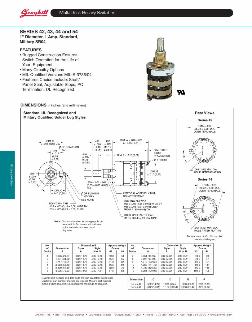
Standard, uL Recognized and Military Qualified Solder Lug Styles
Note: Commonlocationforasinglepoleper deckswitch.Forcommonlocationon multi-poleswitches,seecircuit diagrams.
Forrearviewof45°,60°and90°,seecircuitdiagram.
Rear Views
Series 44
Series 42
DIMENSIONS ininches(andmillimeters)
No. Dimension B Approx. Weight No. Dimension B Approx. Weight of Dimension Style Style Grams of Dimension Style Style Grams Decks A A M or H 42 44 Decks A A M or H 42 44 1 1.025(26,04) .062(1,57) .030(0,76) 40.0 48 7 3.351(85,16) .312(7,92) .280(7,11) 73.0 90 2 1.371(34,82) .062(1,57) .030(0,76) 45.5 55 8 3.697(93,90) .312(7,92) .280(7,11) 78.5 97 3 1.717(43,61) .062(1,57) .030(0,76) 51.0 62 9 4.043(102,69) .312(7,92) .280(7,11) 84.0 104 4 2.063(52,40) .062(1,57) .030(0,76) 56.5 69 10 4.389(111,48) .312(7,92) .280(7,11) 89.5 111 5 2.409(61,19) .062(1,57) .030(0,76) 62.0 76114.735(120,27) .312(7,92) .280(7,11) 95.0 118 6 3.005(76,33) .312(7,92) .280(7,11) 67.5 83 12 5.081(129,06) .312(7,92) .280(7,11) 100.5 125
Dimension C D E FSeries42 .562(14,27) 1.000(25,4) .830(21,08) .093(2,36)Series44 .642(16,31) 1.162(29,51) 1.000(25,4) .121(3,07)
Grayhillpartnumberanddatecodemarkedondetentcoverlabel.Customerpartnumbermarkedonrequest.Militarypartnumbermarkedwhenrequired.ULrecognizedmarkingsasrequired.
1.015±.015(25,78±0,38)DIA.OVERTERMINALS
8
9
101
2 3
45
6
7
GR
Ay
HIL
L
.064(1,63)MIN.DIA.HOLEAFTERPLATING
36°
1.170±.015(29,72±0,38)DIA.OVERTERMINALS
1011
12
3 4
56
78
9G
RA
yH
ILL
.064(1,63)MIN.DIA.HOLEAFTERPLATING
30°
2
115°
DIM.D±.010(0,25)DIA.
.375±.015(9,53
±0,38)
CL OFNON-TURNTAB
OFBUSHINGKEyWAy
CL
SEENOTE
NON-TURNTAB.125±.003(3,18±0,08)WIDEBy.031±.003(0,79±0,08)THICK
DIM.C±.015(0,38)
.219±.005(5,56
±0,13)
DIM.E±.010(0,25)
.250+.001–.002(6,35+0,03–0,05)DIA.
DIM.F±.015(0,38)
DIM.BREF.STUDPROJECTION
#1THREAD
DIM.A+.046–.020(+0,05–0,51)
.250±.020(6,35±0,51)
.437±.020(11,10±0,51)
.437±.020(11,10±0,51)
3/8-32UNEF-2ATHREAD(MTG.HOLE=3/8DIA.MIN.)
BUSHINGKEyWAy.066±.002(1,68±0,05)WIDEBy.036±.003(0,91±0,08)DEEPFROMA.375(9,53)DIA.
INTEGRALASSEMBLyNUT,DONOTREMOVE
SERIES 42, 43, 44 and 541" Diameter, 1 Amp, Standard, Military SR04
FEAtuRES•RuggedConstructionEnsures
SwitchOperationfortheLifeof yourEquipment
•ManyCircuitryOptions•MILQualifiedVersionsMIL-S-3786/04•FeaturesChoiceInclude:Shaft/
PanelSeal,AdjustableStops,PCTermination,ULRecognized
Grayhil l , Inc. • 561 Hil lgrove Avenue • LaGrange, I l l inois 60525-5997 • USA • Phone: 708-354-1040 • Fax: 708-354-2820 • www.grayhil l .com
Rotary S
witches
Multi-Deck Rotary Switches
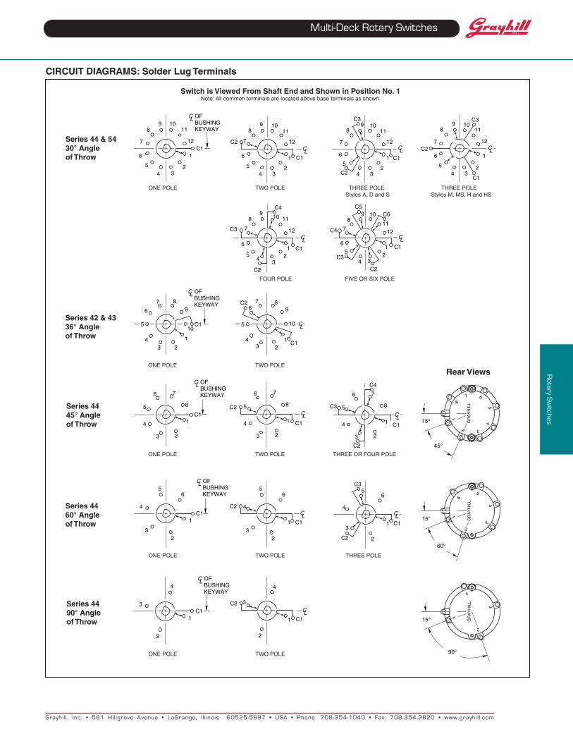
CIRCuIt DIAGRAMS: Solder Lug terminals
Switch is Viewed From Shaft End and Shown in Position No. 1Note:Allcommonterminalsarelocatedabovebaseterminalsasshown.
ONEPOLE TWOPOLETHREEPOLE THREEPOLE StylesA,DandS StylesM,MS,HandHS
ONEPOLE TWOPOLE
ONEPOLE TWOPOLETHREEORFOURPOLE
Rear Views
ONEPOLE TWOPOLE
ONEPOLE TWOPOLETHREEPOLE
FOURPOLE FIVEORSIXPOLE
Series 44 60° Angle of throw
Series 42 & 4336° Angle of throw
Series 44 45° Angle of throw
Series 44 90° Angle of throw
Series 44 & 5430° Angle of throw
C1
1011
12
1
234
5
6
7
89
CL OFBUSHINGKEyWAy
CLC1
C2
1011
12
1
234
5
6
7
89
C1
C2
C310
11
12
1
234
5
6
7
89
CL
C1
C2
C310
11
12
1
234
5
6
7
89
C L
C4
C1
C2
C3
10 11
12
12
34
5
6
7
89
CLC1
C2
C3
C4
C5C610
1112
12
34
5
6
7
89
CL
43 2
1
10
98
5
6
7
C1
CL OFBUSHINGKEyWAy
43 2
1
10
98
5
67
C1
C2
C L
C1
7
8
1
23
4
5
6
CL OFBUSHINGKEyWAy
C1
C2
7
8
1
23
4
5
6
C L
C4
7
8
23
4
5
6
C1
C2
C3
C L1
81
2 3
45
67
GR
Ay
HIL
L
15°
45°
C1
CL OFBUSHINGKEyWAy6
1
23
4
5
C1
C2
6
1
23
4
5
CLC1
C2
C3
C L
6
1
2
3
4
5
1
2
34
5
6
GR
Ay
HIL
L
15°
60°
C1
4
1
2
3
CL OFBUSHINGKEyWAy
CLC1
C2
4
1
2
3
1
2
3
4
GR
Ay
HIL
L
15°
90°
Grayhil l , Inc. • 561 Hil lgrove Avenue • LaGrange, I l l inois 60525-5997 • USA • Phone: 708-354-1040 • Fax: 708-354-2820 • www.grayhil l .com
Rotary S
witches
Multi-Deck Rotary Switches
ThestandardandULrecognizedswitchesarealsoavailablewithadjustablestops.Tworemovablestopwashersallowyou to limit thenumberofswitch positions as needed. A knurled nut issuppliedtosecurethewashersifdesired.These switches have no bushing keyway.Allotherdimensions,ratingsandcharacteristicsarethesameasthestandardfixedstopstyles.Althoughnotmilitaryqualified, theadjustablestylesareusefulinmilitaryequipmentprototypes.However,whensubmittingtheequipmentforgovernmentapproval, the fixed stop qualified style shouldbesubstituted.
Equivalent StylesFor style 42A36, use 42D36,For style 44A30, use 44D30For style 42M36, use 42D36 initially
ADJuStABLE StOP SWItCHES: Series 42 and 44
Front Views
Series42 Series44
Switch is Viewed From Shaft End and Shown in Position No. 1
Note:Allcommonterminalsarelocatedabovebaseterminalsasshown.
PC BOARD MOuNtING PAttERN
terminationOne-sidedterminationisstandardforswitcheswith2to5positions per pole.Two-sided termination is standard forswitcheswith6thru10positionsperpole.
6thru10positionsper pole and ter-minals from oneside of switch areavailableonspecialorder.SeeSpecialOptions,pageF-10orcontactGrayhill.
Shownforatwodeckswitch
CIRCuIt DIAGRAM: PC Mount
ONEPOLE
Standard Style
DIMENSIONS ininches(andmillimeters)
Grayhillpartnumberanddatecodemarkedondetentcoverlabel.Customerpartnum-bermarkedonrequest.ULrecognizedmarkingasrequired.
CL OFBUSHINGKEyWAy
76 5
4
3
21
8
9
10
C1
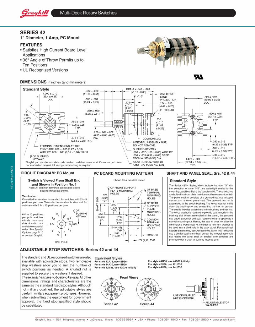
1.000 ± .010 (25,4 ± 0,25)
DIA.
TERMINAL DIMENSIONS AT THIS POINT ARE .050 ± .005 (1,27 ± 0,13)WIDE BY .020 ± .003 (0,51 ± 0,08) THICK
.375 ± .015 (9,53 ± 0,38) TYP.
.750 ± .010 (19,05 ± 0,25)
TYP.
OF BUSHINGKEYWAY
CL
.250 + .001 –.002 (6,35 + 0,03 –0,05) DIA.
3/8-32 UNEF-2A THREAD(MTG. HOLE=3/8 DIA. MIN.)
BUSHING KEYWAY .066 ± .002 (1,68 ± 0,05) WIDE BY .036 ± .003 (0,91 ± 0,08) DEEPFROM A .375 (9,53) DIA.
INTEGRAL ASSEMBLY NUT, DO NOT REMOVE
COMMON LUG
.250 ± .020(6,35 ± 0,51)
.830 ± .010 (21,08 ± 0,25)
DIM. A + .046 – .020 (+1,17 –0,00).437 ± .020
(11,10 ± 0,51)
.600 ± .031 (15,24 ± 0,79)
DIM. B REF.STUDPROJECTION
#1 THREAD
.174 ± .010 (4,42 ± 0,25)
CL CL CL
.174 ± .010 (4,42 ± 0,25)
.786 ± .010 (19,96 ± 0,25) DIA.
.500 ± .015 (12,7 ± 0,38)
TYP.
1.470 ± .020 (37,34 ± 0,51)
TYP.
.735 ± .010 (18,67 ± 0,25) TYP.
.187 ± .015 (4,75 ± 0,38) TYP.
.250 ± .015 (6,35 ± 0,38) TYP.
1 10
65
43
2 98
7
GR
AY
HILL
.219 ± .005(5,56 ± 0,13)
8
9
6
54
3 FIRST
STOP
7
8 9 10
11
65
4 32
FIRS
TS
TOP
ADJUSTABLESTOPWASHERS
USEOFKNURLEDNUTISOPTIONAL
SERIES 421" Diameter, 1 Amp, PC Mount
OFFRONTSUPPORTPLATEMOUNTINGHOLES
C L
.375(9,53)TyP.
.750(19,05)
TyP.
.492(12,50)
.500(12,7)TyP.
.250(6,35)TyP.
.110(2,79)
.174(4,42)TyP.
C L OFREARSUPPORTPLATEMOUNTINGHOLES
C L OFBASETERMINALMOUNTINGHOLES
C L COMMONTERMINALMOUNTINGHOLES
SH
AF
TE
ND
.174(4,42)TyP.
SHAFt AND PANEL SEAL: Srs. 42 & 44
Standard StyleTheSeries42/44Styles,whichincludetheletter"S"withtheexceptionof style "HS",arewatertightsealed to themountingpanelbyutilizingthepanelsealkit.Theseswitchesarebuiltwithafrontplatethatdoesnothaveanon-turntab.Thepanelsealkitconsistsofagroovedhexnut,akeyedwasherandakeyedpanel seal.Thegroovedhexnut isassembledtotheswitchbushing.Thekeyedwasherissliddownthebushingslotandseatedintothehexnutgroove.Thesealislikewiseassembledtothebushingandhexnut.Thekeyedwasherisrequiredtoprovidesealintegrityinthebushingslot.Whenassembledtothepanel, thegroovednut,backingwasherandsealrequirethesamespaceasanormalmountingnut.Hence,thesealkitdoesnotalterthedimensions.Panelsealkit includesanon-turnwashertobeusedintoablindholeinthebackpanel.Forpanelsealkitpartdimensions,seeAccessories.Style"HS"switchesuseasimilarsealingmethod,excepttheintegralassemblynut retains the panel seal. All sealed style switches areprovidedwithashafttobushinginternalseal.
FEAtuRES•SatisfiesHighCurrentBoardLevel
Applications•36°AngleofThrowPermitsupto
TenPositions•ULRecognizedVersions
For style 44M30, use 44D30 initiallyFor style 42u36, use 42uD36For style 44u30, use 44uD30
Grayhil l , Inc. • 561 Hil lgrove Avenue • LaGrange, I l l inois 60525-5997 • USA • Phone: 708-354-1040 • Fax: 708-354-2820 • www.grayhil l .com
Rotary S
witches
Multi-Deck Rotary Switches
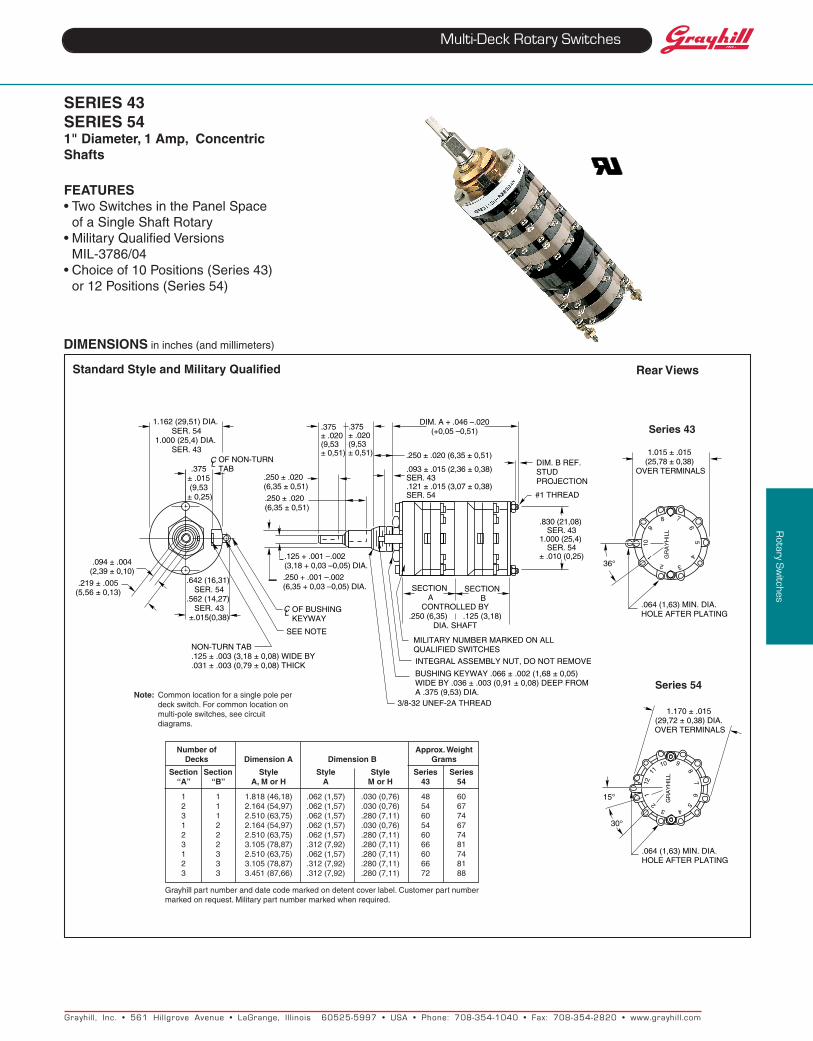
Standard Style and Military Qualified
DIMENSIONS ininches(andmillimeters)
Note: Commonlocationforasinglepoleper deckswitch.Forcommonlocationon multi-poleswitches,seecircuit diagrams.
Rear Views
Series 54
Series 43
Number of Approx. Weight Decks Dimension A Dimension B Grams Section Section Style Style Style Series Series “A” “B” A, M or H A M or H 43 54
1 1 1.818(46,18) .062(1,57) .030(0,76) 48 60 2 1 2.164(54,97) .062(1,57) .030(0,76) 54 67 3 1 2.510(63,75) .062(1,57) .280(7,11) 60 74 1 2 2.164(54,97) .062(1,57) .030(0,76) 54 67 2 2 2.510(63,75) .062(1,57) .280(7,11) 60 74 3 2 3.105(78,87) .312(7,92) .280(7,11) 66 81 1 3 2.510(63,75) .062(1,57) .280(7,11) 60 74 2 3 3.105(78,87) .312(7,92) .280(7,11) 66 81 3 3 3.451(87,66) .312(7,92) .280(7,11) 72 88
Grayhillpartnumberanddatecodemarkedondetentcoverlabel.Customerpartnumbermarkedonrequest.Militarypartnumbermarkedwhenrequired.
1.162(29,51)DIA.SER.54
1.000(25,4)DIA.SER.43
.375±.015(9,53
±0,25)
.642(16,31)SER.54
.562(14,27)SER.43
±.015(0,38)OFBUSHINGKEyWAy
CL
SEENOTE
NON-TURNTAB.125±.003(3,18±0,08)WIDEBy.031±.003(0,79±0,08)THICK
.219±.005(5,56±0,13)
.094±.004(2,39±0,10)
.125+.001–.002(3,18+0,03–0,05)DIA.
.250±.020(6,35±0,51)
CL OFNON-TURNTAB
.250±.020(6,35±0,51)
.093±.015(2,36±0,38)SER.43.121±.015(3,07±0,38)SER.54
.375±.020(9,53±0,51)
.375±.020(9,53±0,51) .250±.020(6,35±0,51)
DIM.A+.046–.020(+0,05–0,51)
DIM.BREF.STUDPROJECTION
#1THREAD
SECTIONA
SECTIONB
3/8-32UNEF-2ATHREAD
BUSHINGKEyWAy.066±.002(1,68±0,05)WIDEBy.036±.003(0,91±0,08)DEEPFROMA.375(9,53)DIA.
INTEGRALASSEMBLyNUT,DONOTREMOVE
.250+.001–.002(6,35+0,03–0,05)DIA.
.830(21,08)SER.43
1.000(25,4)SER.54
±.010(0,25)
CONTROLLEDBy.250(6,35).125(3,18)
DIA.SHAFT
MILITARyNUMBERMARKEDONALLQUALIFIEDSWITCHES
1.015±.015(25,78±0,38)
OVERTERMINALS
36°
GR
Ay
HIL
L
.064(1,63)MIN.DIA.HOLEAFTERPLATING
8
9
101
2 3
45
6
7
1.170±.015(29,72±0,38)DIA.OVERTERMINALS
1011
12
3 4
56
78
9
GR
Ay
HIL
L
.064(1,63)MIN.DIA.HOLEAFTERPLATING
30°
2
115°
SERIES 43 SERIES 541" Diameter, 1 Amp, Concentric Shafts
FEAtuRES•TwoSwitchesinthePanelSpace
ofaSingleShaftRotary•MilitaryQualifiedVersions MIL-3786/04•Choiceof10Positions(Series43)
or12Positions(Series54)
Grayhil l , Inc. • 561 Hil lgrove Avenue • LaGrange, I l l inois 60525-5997 • USA • Phone: 708-354-1040 • Fax: 708-354-2820 • www.grayhil l .com
Rotary S
witches
Multi-Deck Rotary Switches
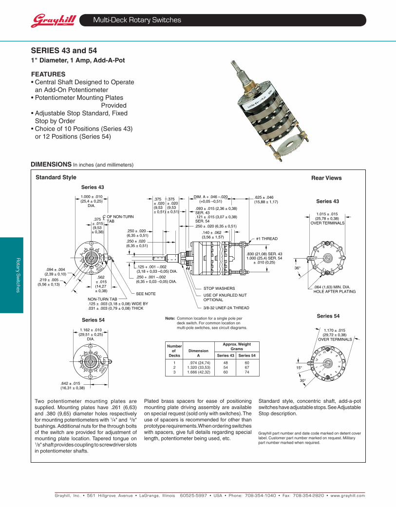
SERIES 43 and 541" Diameter, 1 Amp, Add-A-Pot
FEAtuRES•CentralShaftDesignedtoOperate
anAdd-OnPotentiometer•PotentiometerMountingPlates
Provided•AdjustableStopStandard,Fixed
StopbyOrder•Choiceof10Positions(Series43)
or12Positions(Series54)
Standard Style
Series 43
Note: Commonlocationforasinglepoleper deckswitch.Forcommonlocationon multi-poleswitches,seecircuitdiagrams.
Number of Dimension Decks A Series 43 Series 54
1 .974(24,74) 48 60 2 1.320(33,53) 54 67 3 1.666(42,32) 60 74
Approx. WeightGrams
Series 54
DIMENSIONS Ininches(andmillimeters)
Two potentiometer mounting plates aresupplied. Mounting plates have .261 (6,63)and .380(9,65)diameterholes respectivelyformountingpotentiometerswith1/4"and3/8"bushings.Additionalnutsforthethroughboltsof theswitchareprovidedforadjustmentofmountingplate location.Tapered tongueon1/8"shaftprovidescouplingtoscrewdriverslotsinpotentiometershafts.
Rear Views
Series 54
Series 43
23
45
67
8
9
1.000±.010(25,4±0,25)
DIA.
.375±.015(9,53
±0,38)
SEENOTENON-TURNTAB.125±.003(3,18±0,08)WIDEBy.031±.003(0,79±0,08)THICK
CL OFNON-TURNTAB
.562±.015(14,27±0,38)
.125+.001–.002(3,18+0,03–0,05)DIA.
.250+.001–.002(6,35+0,03–0,05)DIA.
.250±.020(6,35±0,51)
.250±.020(6,35±0,51)
.250±.020(6,35±0,51)
.375±.020(9,53±0,51)
.375±.020(9,53±0,51)
.093±.015(2,36±0,38)SER.43.121±.015(3,07±0,38)SER.54
.140±.062(3,56±1,57)
DIM.A+.046–.020(+0,05–0,51)
.625±.046(15,88±1,17)
#1THREAD
.830(21,08)SER.431.000(25,4)SER.54
±.010(0,25)
3/8-32UNEF-2ATHREAD
STOPWASHERS
USEOFKNURLEDNUTOPTIONAL
FIRST
STOP
.219±.005(5,56±0,13)
.094±.004(2,39±0,10)
1.015±.015(25,78±0,38)
OVERTERMINALS
.064(1,63)MIN.DIA.HOLEAFTERPLATING
8
9
10
2 3
45
6
7
36°
1
FIRST
STOP2
34
56
7
8 10
11
9
1.162±.010(29,51±0,25)
DIA.
.642±.015(16,31±0,38)
1.170±.015(29,72±0,38)
OVERTERMINALS
12
9
87
6
432
1
5
1110
30°
15°
Plated brass spacers for ease of positioningmountingplatedrivingassemblyareavailableonspecialrequest(soldonlywithswitches).Theuseofspacersisrecommendedforotherthanprototyperequirements.Whenorderingswitcheswithspacers,givefulldetailsregardingspeciallength,potentiometerbeingused,etc.
Standard style, concentric shaft, add-a-potswitcheshaveadjustablestops.SeeAdjustableStopdescription.
Grayhillpartnumberanddatecodemarkedondetentcoverlabel.Customerpartnumbermarkedonrequest.Militarypartnumbermarkedwhenrequired.
Grayhil l , Inc. • 561 Hil lgrove Avenue • LaGrange, I l l inois 60525-5997 • USA • Phone: 708-354-1040 • Fax: 708-354-2820 • www.grayhil l .com
Rotary S
witches
Multi-Deck Rotary Switches
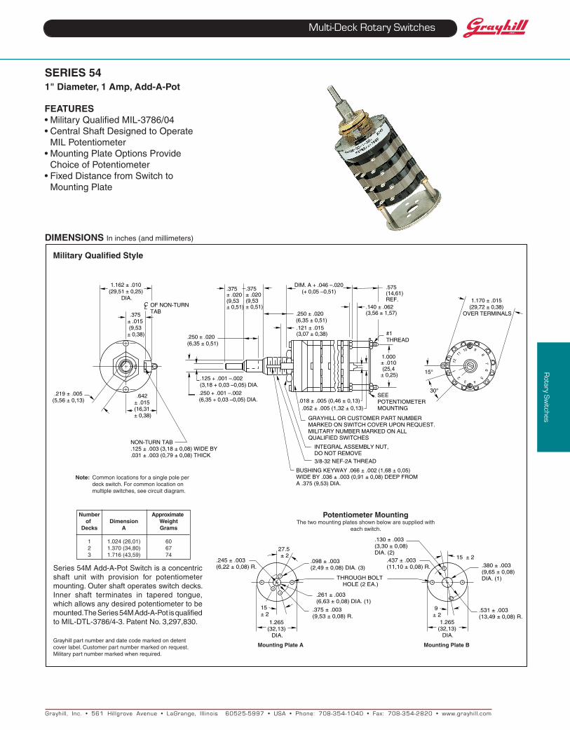
SERIES 541" Diameter, 1 Amp, Add-A-Pot
FEAtuRES•MilitaryQualifiedMIL-3786/04•CentralShaftDesignedtoOperate
MILPotentiometer•MountingPlateOptionsProvide
ChoiceofPotentiometer•FixedDistancefromSwitchto
MountingPlate
Military Qualified Style
Note: Commonlocationsforasinglepoleper deckswitch.Forcommonlocationon multipleswitches,seecircuitdiagram.
Number Approximate of Dimension Weight Decks A Grams
1 1.024(26,01) 60 2 1.370(34,80) 67 3 1.716(43,59) 74
DIMENSIONS Ininches(andmillimeters)
Potentiometer MountingThetwomountingplatesshownbelowaresuppliedwith
eachswitch.
Mounting Plate A Mounting Plate B
Series54MAdd-A-PotSwitchisaconcentricshaft unit with provision for potentiometermounting.Outershaftoperatesswitchdecks.Inner shaft terminates in tapered tongue,whichallowsanydesiredpotentiometertobemounted.TheSeries54MAdd-A-PotisqualifiedtoMIL-DTL-3786/4-3.PatentNo.3,297,830.
Grayhillpartnumberanddatecodemarkedondetentcoverlabel.Customerpartnumbermarkedonrequest.Militarypartnumbermarkedwhenrequired.
DIM.A+.046–.020(+0,05–0,51)
.642±.015(16,31±0,38)
NON-TURNTAB.125±.003(3,18±0,08)WIDEBy.031±.003(0,79±0,08)THICK
.219±.005(5,56±0,13)
CL OFNON-TURNTAB.375
±.015(9,53
±0,38)
1.162±.010(29,51±0,25)
DIA.
.125+.001–.002(3,18+0,03–0,05)DIA.
.250+.001–.002(6,35+0,03–0,05)DIA.
.250±.020(6,35±0,51)
.121±.015(3,07±0,38)
.375±.020(9,53±0,51)
.375±.020(9,53±0,51)
.250±.020(6,35±0,51)
.140±.062(3,56±1,57)
1.000±.010(25,4
±0,25)
3/8-32NEF-2ATHREAD
INTEGRALASSEMBLyNUT,DONOTREMOVE
BUSHINGKEyWAy.066±.002(1,68±0,05)WIDEBy.036±.003(0,91±0,08)DEEPFROMA.375(9,53)DIA.
GRAyHILLORCUSTOMERPARTNUMBERMARKEDONSWITCHCOVERUPONREQUEST.MILITARyNUMBERMARKEDONALLQUALIFIEDSWITCHES
.575(14,61)REF.
#1THREAD
SEEPOTENTIOMETERMOUNTING
1.170±.015(29,72±0,38)
OVERTERMINALS
12
9
87
6
432
1
511
10
30°
15°
.018±.005(0,46±0,13).052±.005(1,32±0,13)
1.265 (32,13)
DIA.
27.5 ± 2
.098 ± .003 (2,49 ± 0,08) DIA. (3)
THROUGH BOLT HOLE (2 EA.)
15 ± 2
.245 ± .003 (6,22 ± 0,08) R.
.375 ± .003 (9,53 ± 0,08) R.
.261 ± .003 (6,63 ± 0,08) DIA. (1)
1.265 (32,13)
DIA.
15 ± 2
9 ± 2
.437 ± .003 (11,10 ± 0,08) R.
.531 ± .003 (13,49 ± 0,08) R.
.380 ± .003 (9,65 ± 0,08) DIA. (1)
.130 ± .003 (3,30 ± 0,08) DIA. (2)
Grayhil l , Inc. • 561 Hil lgrove Avenue • LaGrange, I l l inois 60525-5997 • USA • Phone: 708-354-1040 • Fax: 708-354-2820 • www.grayhil l .com
Rotary S
witches
Multi-Deck Rotary Switches
MILItARy QuALIFIEDSingle Shaft SwitchesThe military styles of the single shaft Series42and44rotaryswitchesarequalifiedtoMIL-DTL-3786/4, specificallySR04-1.Qualificationincludes two temperature ranges. UnsealedstylesM,MB,MGandMBGarequalifiedfor-65to85°C.UnsealedstylesH,HB,HGandHBG,plussealedstylesHS,HBS,HGSandHBGSare qualified for -65°C to 125°C. Qualificationincludeslowlevelswitchingandshaftgroundingas specified in MIL-DTL-3786. Qualificationincludes30°,36°,45°,60°and90°anglesofthrowwithsolderlugterminals.Themilitarystylesaredimensionallythesameasthestandardstyleswithtwoexceptions.Thelocationofthecommonforthe3-poleswitchdiffers(seecircuitdiagrams)andthenon-turntabforstylesHS,HBS,HGSandHBGSdifferspertheShaftandPanelSealdescriptionfollowing.
two Switches, Concentric ShaftsTheMstyleof theconcentricshaftSeries43and54switchesisqualifiedtoMIL-DTL-3786/4,
specifically SR04-2. Unsealed switches arequalified for -65°C to 85°C in 30°, 36°, 45°,60°and90°throws.Thestandardandmilitarystylesoftheconcentricswitcheshavethesamedimensionswiththeexceptionofthelocationofthe3polecommon(seecircuitdiagrams).The30°and36°throwsaredescribedintheorderinginformation.Ifthe45°,60°and90°throwsarerequired,theycanbeprovidedinSectionAofthe Series 54 Rotary Switches; see StandardOptions,pageJ-9.
Add-A-Pot SwitchesThe military style of the add-a-pot Series 54switchisqualifiedtoMIL-DTL-3786/4,specificallySR04-3.Theseunsealedswitchesarequalifiedfor-65°Cto85°Cin30°,45°,60°and90°throws.Thedimensionsof themilitarystyleadd-a-potswitchesarenotthesameasthestandardadd-a-potswitches;seedrawings.
All Qualified SwitchesCompleteelectricalratingsandcharacteristicsforallofthesequalifiedswitchesarelistedon
the following pages. Standard variations suchasterminals,shaftand/orbushing lengthetc.,whichdonotaffectperformance,canbemarkedas qualified product. Adjustable stops cannotbequalified.ContactGrayhill fordetailsaboutvariations.
MilitaryqualifiedswitchesmaybeorderedbythemilitaryMnumberlistedinMIL-DTL-3786/4orbytheGrayhillpartnumber.Theywillbemarkedtospecifications.
MILItARy QuALIFIED SHAFt AND PANEL SEAL:Styles HS, HBS, HGS and HBGSTheshaftissealedtothebushingbyaninternalO-ringperMIL-P-5516B.Thebushingissealedtothepanelwithasiliconerubberwasherandastainlesssteelbackingwasher.Thecombineduncompressedthicknessis0.055"(1,40).Sincethisswitchhasaflatcover,anon-turnwasherissupplied(seePanelSealKit).Ifusingit,mountitinfrontofthepanel.
SPECIFICAtIONS:
Electrical RatingsStandard StyleRated: To make and break the followingloads:
Angle of throw 30° or 36° 45° or 60° 90° 115Vacresistive 1amp 5amps 5amps 6-28Vdcresistive 1amp 1amp 2amps 115Vacinductive 0.25amp 2amps 2amps 115Vdcinductive 0.02amp — — 6-28Vdcinductive 0.10amp — — 115Vdcresistive 0.10amp — —
Tocarry10ampscontinuously.
Contact Resistance:50milliohmsmaximumInsulation Resistance: 1,000megaohmsminimumVoltage Breakdown:1,000Vacinitially(500Vacorbetteraftermostenvironmentaltests)Life Expectancy:100,000mechanicalcyclesof operation. Note: Actual life is determinedby a number of factors, including electricalloading,rateofrotationandenvironment,aswellasmaximumvoltagebreakdownrequiredattheendoflife.
uL Recognition–Styles uA, uD, uM, uP, uS and uSPGrayhillstylesAandMandtheirvariations(D,P,SandSP)oftheSeries42,43,44and54rotaryswitches have been tested by UnderwritersLaboratories.TheletterUinthestyleindicatesproper marking as required by UnderwritersLaboratories.TheseswitchesarerecognizedunderfilenumberE35289.TheULratingfortheSeries42,43,44and54isasfollows:Electrical Parameters: styleUA=1.0ampereat125Vac.StyleUM=1.0ampereat125Vacandalso.5ampereat125Vac,inductiveload,0.75to0.8powerfactor.Ratingbasedonthefollowingcriteria:
Overload: 50 operations at 150% rated ACloadEndurance:6000operationsattheratedloadwith 1000 Vac dielectric strength before andaftertesttemperature Rise:Nottoexceed30°CwhencarryingratedACloadaftertest.Note: alldimensionaldrawingsforthestandardstyleSeries42,43,44and54alsoapplytotheseswitches,withtheexceptionthatswitchesaremarkedperspecifications.
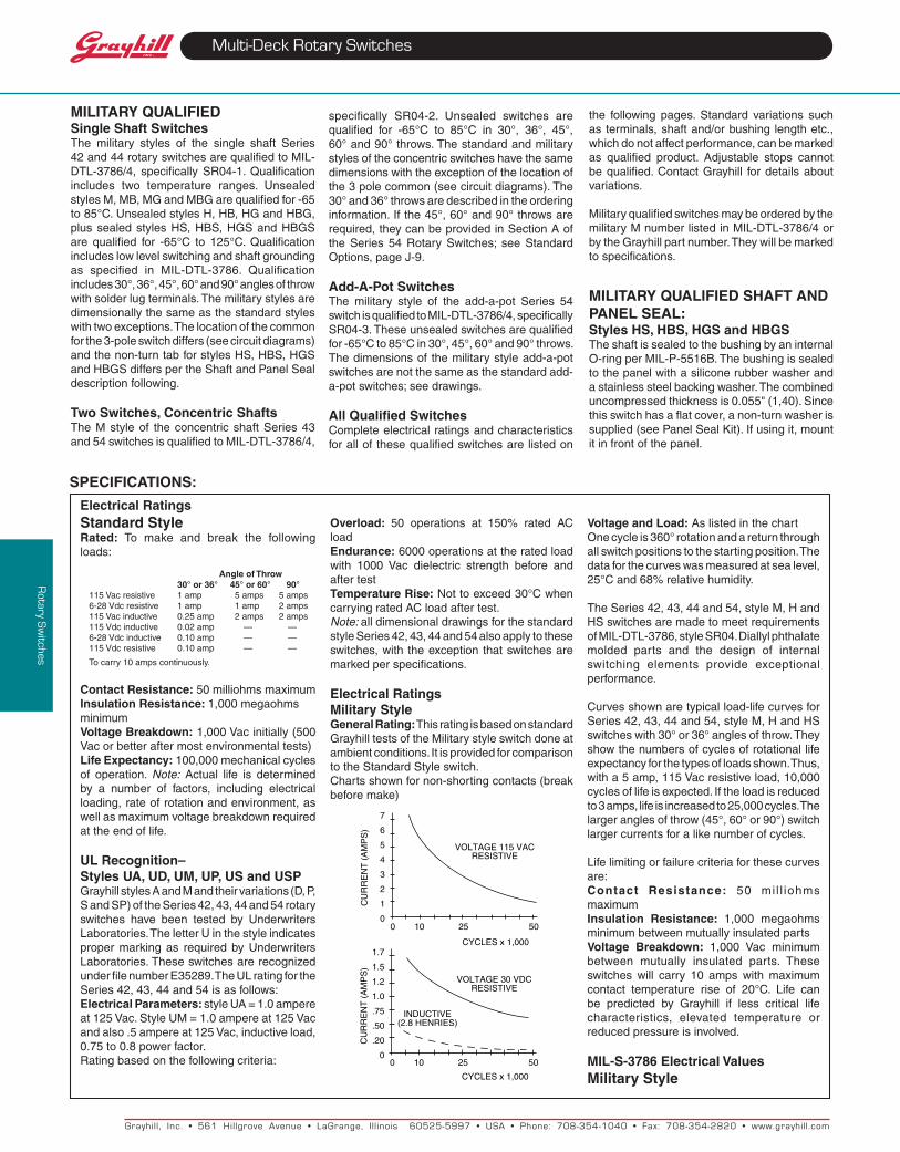
Electrical RatingsMilitary StyleGeneral Rating:ThisratingisbasedonstandardGrayhilltestsoftheMilitarystyleswitchdoneatambientconditions.ItisprovidedforcomparisontotheStandardStyleswitch.Chartsshownfornon-shortingcontacts(breakbeforemake)
7
6
5
4
3
2
1
00
CyCLESx1,000
10 25 50
CU
RR
EN
T(
AM
PS
)
VOLTAGE115VACRESISTIVE
CyCLESx1,000
0 10 25 50
1.7
1.5
1.2
1.0
.75
.50
.20
0
CU
RR
EN
T(
AM
PS
)
VOLTAGE30VDCRESISTIVE
INDUCTIVE(2.8HENRIES)
Voltage and Load:AslistedinthechartOnecycleis360°rotationandareturnthroughallswitchpositionstothestartingposition.Thedataforthecurveswasmeasuredatsealevel,25°Cand68%relativehumidity.
TheSeries42,43,44and54,styleM,HandHSswitchesaremadetomeetrequirementsofMIL-DTL-3786,styleSR04.Diallylphthalatemolded parts and the design of internalswitching elements provide exceptionalperformance.
Curvesshownaretypicalload-lifecurvesforSeries42,43,44and54,styleM,HandHSswitcheswith30°or36°anglesofthrow.Theyshowthenumbersofcyclesofrotationallifeexpectancyforthetypesofloadsshown.Thus,witha5amp,115Vacresistiveload,10,000cyclesoflifeisexpected.Iftheloadisreducedto3amps,lifeisincreasedto25,000cycles.Thelargeranglesofthrow(45°,60°or90°)switchlargercurrentsforalikenumberofcycles.
Lifelimitingorfailurecriteriaforthesecurvesare:Contact Resistance: 50 mi l l iohmsmaximumInsulation Resistance: 1,000 megaohmsminimumbetweenmutuallyinsulatedpartsVoltage Breakdown: 1,000 Vac minimumbetween mutually insulated parts. Theseswitches will carry 10 amps with maximumcontact temperature rise of 20°C. Life canbe predicted by Grayhill if less critical lifecharacteristics, elevated temperature orreducedpressureisinvolved.
MIL-S-3786 Electrical ValuesMilitary Style
Grayhil l , Inc. • 561 Hil lgrove Avenue • LaGrange, I l l inois 60525-5997 • USA • Phone: 708-354-1040 • Fax: 708-354-2820 • www.grayhil l .com
Rotary S
witches
Multi-Deck Rotary Switches
SPECIFICAtIONS:
StyleMswitches,at85°C,approximately68%humidityandsealevelpressureandstyleHandHSat125°Chavebeentestedtomakeand break the following loads as stated inMIL-DTL-3786/SR04; 250 milliamperes at28Vdcresistive,100milliamperesat28Vdcinductive(2.8henries);75milliamperesat115Vacresistive.
These switches have also been tested atreduced barometric pressure (70,000 feet),25°Catapproximately68%relativehumiditytomakeandbreakthefollowingloadsasstatedin MIL-DTL-3786/SR04; 200 milliamperes,28 Vdc resistive; 25 milliamperes, 28 Vdcinductive(2.8henries);20milliamperes,115Vacresistive.Whentestedtotheseloadsandconditions the style M, H and HS switchesmeetthefollowinglifelimitingorfailurecriteriaafter25,000cyclesinaccordancewithMIL-S-3786.
Contact Resistance: 50 mi l l iohmsmaximumInsulation Resistance: 1,000 megaohmsminimumbetweenterminalsandshaftsDielectric Strength: 1,000Vac(atmosphericpressure) and 450 Vac (reduced pressure)minimumbetweenmutuallyinsulatedparts.
Whentestedatsealevel25°Cand68%relativehumiditywith failurecriteriaof50milliohmsmax.and750Vacbreakdownvoltage,theseswitches will make and break the followingloads:250mAat28Vdc,inductive(2.8henries);1.25ampsat28Vdcresistive;2.0ampsat115Vac,60Hzresistive,for10,000cycles.
These switches also meet MIL-DTL-3786/SR04 for moisture resistance, medium andhighshock,vibration(10to2000cps),thermalshock(-65°Cto125°C),saltspray,explosionandterminalpull.
Materials and FinishesStandard StyleBases: Melamine per (MIL-M-14) ASTM-D-5948Cover, Deck Separators, End Plate and RotorMounting Plate: Phenolic per (MIL-M-14)ASTM-D-5948Mounting Bushings:Brass,tin/zinc-plated.Shaft, Cover Plate, Retaining Rings, through Bolts, Shaft Extensions, Stop Arm, thrust Washers Stop Washers and Rear Support Plate:StainlessSteelDetent Balls:Steel,nickel-platedDetent Springs:TinnedmusicwireRotor Contact, Stator (Base) Contacts: Silveralloyterminals (Except Common): Brass, tinplatedCommon Plate, Including Solder Lug: Brass,silver-plated.0003"minimumMounting Hardware:Twomountingnuts.094"(2,39) thickby .562" (14,27)across flatsandoneinternaltoothlockwasheraresuppliedwitheachswitch.Stud Nuts, Mounting Nuts, Lock Washers:Tin/zinc-platedorstainlesssteel.
Materials and FinishesMilitary QualifiedBases:Diallylper(MIL-M-14)ASTM-D-5948Cover, Deck Separators, End Plate and Rotor Mounting Plate: Diallylper(MIL-M-14)ASTM-D-5948
Mounting Bushings: Brass,tin/zinc-plated.Shaft, Cover Plate, Retaining Rings, through Bolts, Shaft Extensions, Stop Arm, Stop Washers, thrust Washers and Rear Support Plate:StainlesssteelDetent Balls:Steel,nickel-platedDetent Springs: TinnedmusicwireRotor Contact: Silveralloyterminals, Common Plate including Solder Lug:Brass,silver-plated.0003"minimumMounting Hardware: Twomountingnuts.094"thickby.562"acrossflatsandoneinternaltoothlockwasheraresuppliedwitheachswitch.Stud Nuts, Mounting Nuts, Lock Washers:Tin/zinc-platedorstainlesssteel.
Additional CharacteristicsStandard Style and Military QualifiedContact: Shorting or non-shorting wipingcontacts with over 150 grams of contactforceRotational torque: 8-115 ounce-inchesdependinguponthenumberofpolesperdeck,numberofdecksandangleofthrowMechanical Life Expectancy: 100,000cyclesofoperationShaft Flat Orientation: Flat oppositecontactingpositionofpolenumberone(Seecircuitdiagram).Stop Strength: ForStandardstyle:15pound-inchesminimum.ForAdjustablestopstyles:12pound-inchesExtended Stud: Singleshaftswitchesofsixormoredecksandconcentricshaftswitchesofacombinationoffiveormoredecks(Standardstyle) or four or more decks (Military style)havelongerstudswithextramountingnutsforrecommendeddoubleendmount.
Grayhil l , Inc. • 561 Hil lgrove Avenue • LaGrange, I l l inois 60525-5997 • USA • Phone: 708-354-1040 • Fax: 708-354-2820 • www.grayhil l .com
Rotary S
witches
Multi-Deck Rotary Switches
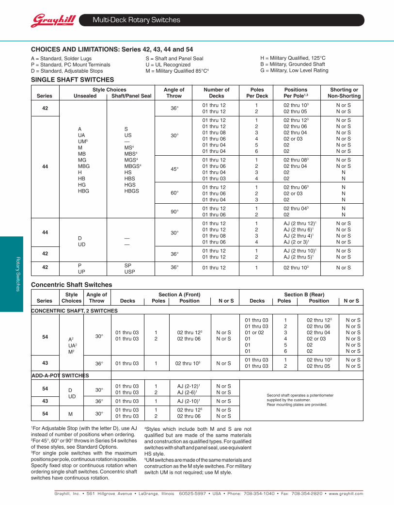
CHOICES AND LIMItAtIONS: Series 42, 43, 44 and 54A=Standard,SolderLugsP=Standard,PCMountTerminalsD=Standard,AdjustableStops
S=ShaftandPanelSealU=ULRecognizedM=MilitaryQualified85°C4
H=MilitaryQualified,125°CB=Military,GroundedShaftG=Military,LowLevelRating
SINGLE SHAFt SWItCHES Style Choices Angle of Number of Poles Positions Shorting or Series unsealed Shaft/Panel Seal throw Decks Per Deck Per Pole1,3 Non-Shorting
01thru12 1 02thru103 NorS01thru12 2 02thru05 NorS
01thru12 1 02thru123 NorS01thru12 2 02thru06 NorS01thru08 3 02thru04 NorS01thru06 4 02or03 NorS01thru04 5 02 NorS01thru04 6 02 NorS
01thru12 1 02thru083 NorS01thru06 2 02thru04 NorS01thru04 3 02 N01thru03 4 02 N
01thru12 1 02thru063 N01thru06 2 02or03 N01thru04 3 02 N
01thru12 1 02thru043 N01thru06 2 02 N
01thru12 1 AJ(2thru12)1 NorS01thru12 2 AJ(2thru6)1 NorS01thru08 3 AJ(2thru4)1 NorS01thru06 4 AJ(2or3)1 NorS
01thru12 1 AJ(2thru10)1 NorS01thru12 2 AJ(2thru5)1 NorS
01thru12 1 02thru103 NorS
A SUA USUM5 —M MS4
MB MBS4
MG MGS4
MBG MBGS4
H HSHB HBSHG HGSHBG HBGS
D —UD —
P SPUP USP
1ForAdjustableStop(withtheletterD),useAJinsteadofnumberofpositionswhenordering.2For45°,60°or90°throwsinSeries54switchesofthesestyles,seeStandardOptions.3For single pole switches with the maximumpositionsperpole,continuousrotationispossible.Specifyfixedstoporcontinuousrotationwhenorderingsingleshaftswitches.Concentricshaftswitcheshavecontinuousrotation.
Style Angle of Section A (Front) Section B (Rear) Series Choices throw Decks Poles Position N or S Decks Poles Position N or S
CONCENtRIC SHAFt, 2 SWItCHES
A2
UA2
M2
DUD
M
54
43
54
43
54
ADD-A-POt SWItCHES
Secondshaftoperatesapotentiometersuppliedbythecustomer.Rearmountingplatesareprovided.
30°
36°
30°
36°
30°
01thru03 1 02thru105 NorS
Concentric Shaft Switches
36°
30°
45°
60°
90°
30°
36°
36°
42
44
44
42 42
01thru03 1 02thru123 NorS 01thru03 2 02thru06 NorS01thru03 1 02thru123 NorS 01or02 3 02thru04 NorS01thru03 2 02thru06 NorS 01 4 02or03 NorS 01 5 02 NorS 01 6 02 NorS
01thru03 1 02thru103 NorS 01thru03 2 02thru05 NorS
01thru03 1 AJ(2-12)1 NorS01thru03 2 AJ(2-6)1 NorS
01thru03 1 AJ(2-10)1 NorS
01thru03 1 02thru125 NorS01thru03 2 02thru06 NorS
4Styles which include both M and S are notqualified but are made of the same materialsandconstructionasqualifiedtypes.Forqualifiedswitcheswithshaftandpanelseal,useequivalentHSstyle.5UMswitchesaremadeofthesamematerialsandconstructionastheMstyleswitches.FormilitaryswitchUMisnotrequired;useMstyle.
Grayhil l , Inc. • 561 Hil lgrove Avenue • LaGrange, I l l inois 60525-5997 • USA • Phone: 708-354-1040 • Fax: 708-354-2820 • www.grayhil l .com
Rotary S
witches
Multi-Deck Rotary Switches
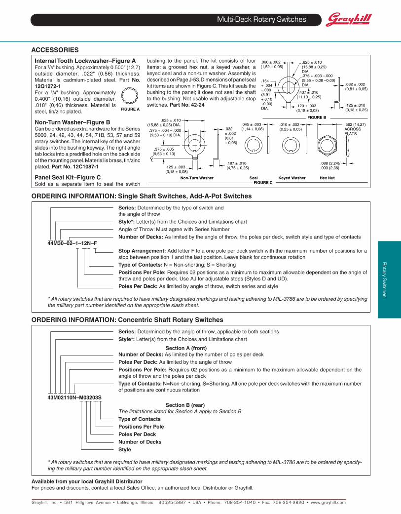
ACCESSORIES
Internal tooth Lockwasher–Figure AFora3/8"bushing.Approximately0.500"(12,7)outside diameter, .022" (0,56) thickness.Material is cadmium-plated steel. Part No. 12Q1272-1For a 1/4" bushing. Approximately0.400" (10,16) outside diameter,.018" (0,46) thickness. Material issteel,tin/zincplated.
Non-turn Washer–Figure BCanbeorderedasextrahardwarefortheSeries5000,24,42,43,44,54,71B,53,57and59rotaryswitches.Theinternalkeyofthewasherslidesintothebushingkeyway.Therightangletablocksintoapredrilledholeonthebacksideofthemountingpanel.Materialisbrass,tin/zincplated.Part No. 12C1087-1
Panel Seal Kit–Figure CSold as a separate item to seal the switch
ORDERING INFORMAtION: Single Shaft Switches, Add-A-Pot Switches
ORDERING INFORMAtION: Concentric Shaft Rotary Switches
Series:Determinedbythetypeofswitchand theangleofthrow
Style*:Letter(s)fromtheChoicesandLimitationschart
AngleofThrow:MustagreewithSeriesNumber
Number of Decks:Aslimitedbytheangleofthrow,thepolesperdeck,switchstyleandtypeofcontacts44M30–02–1–12N–F Stop Arrangement:AddletterFtoaonepoleperdeckswitchwiththemaximumnumberofpositionsfora
stopbetweenposition1andthelastposition.Leaveblankforcontinuousrotation
type of Contacts:N=Non-shorting;S=Shorting
Positions Per Pole:Requires02positionsasaminimumtomaximumallowabledependentontheangleofthrowandpolesperdeck.UseAJforadjustablestops(StylesDandUD).
Poles Per Deck:Aslimitedbyangleofthrow,switchseriesandstyle
* All rotary switches that are required to have military designated markings and testing adhering to MIL-3786 are to be ordered by specifying the military part number identified on the appropriate slash sheet.
Series:Determinedbytheangleofthrow,applicabletobothsections
Style*:Letter(s)fromtheChoicesandLimitationschart Section A (front) Number of Decks:Aslimitedbythenumberofpolesperdeck Poles Per Deck:Aslimitedbytheangleofthrow
Positions Per Pole:Requires02positionsasaminimumtothemaximumallowabledependentontheangleofthrowandthepolesperdeck
type of Contacts:N=Non-shorting,S=Shorting.Allonepoleperdeckswitcheswiththemaximumnumberofpositionsarecontinuousrotation
43M02110N–M03203S Section B (rear) The limitations listed for Section A apply to Section B
type of Contacts Positions Per Pole Poles Per Deck Number of Decks Style
* All rotary switches that are required to have military designated markings and testing adhering to MIL-3786 are to be ordered by specify-ing the military part number identified on the appropriate slash sheet.
Available from your local Grayhill DistributorForpricesanddiscounts,contactalocalSalesOffice,anauthorizedlocalDistributororGrayhill.
Non-turn Washer Seal Keyed Washer Hex Nut FIGuRE C
.625±.010(15,88±0,25)DIA..375+.004–.000(9,53+0,10)DIA.
.375±.005(9,53±0,13)
.125±.003(3,18±0,08)
C L
.032±.002(0,81±0,05)
.187±.010(4,75±0,25)
.045±.003(1,14±0,08)
.010±.002(0,25±0,05)
.562(14,27)ACROSSFLATS
.088(2,24)/
.093(2,36)
.120±.003(3,18±0,08)
.060±.002(1,52±0,05)
.154+.004–.000(3,91+0,10–0,00)DIA.
.437±.010(11,10±0,25)
.625±.010(15,88±0,25)DIA..376+.003–.000(9,55+0,08–0,00)DIA.
.125±.010(3,18±0,25)
.032±.002(0,81±0,05)
FIGuRE B
FIGuRE A
bushing to the panel.The kit consists of fouritems: a grooved hex nut, a keyed washer, akeyedsealandanon-turnwasher.AssemblyisdescribedonPageJ-53.DimensionsofpanelsealkititemsareshowninFigureC.Thiskitsealsthebushingtothepanel;itdoesnotsealtheshafttothebushing.Notusablewithadjustablestopswitches. PartNo. 42-24
Related Documents