1 Model: MCI-3000V4 General Information The MCI-3000V4 is a multi units / apartments wireless intercom system that operates on the GMS mobile phone network. It is very cost effective and saves you enormous hours of labor in installation and kilometers of wiring. The MCI-3000V4 is operational on the 3G & 4G network and can be used for a building of apartments or for any complex with up to 333 units. The installation takes a few minutes and requires connection to power supply and to the latch of the pedestrian gate and to the driveway gate automation, if there is one. The unit requires a SIM card to be used to make calls to the units. In addition, the MCI-3000V4 has an anti-vandal metal keypad that allows the users to open the gate with a four digit pin code. Explanation of how the intercom works : There is a sign on the door station that says: “PRESS THE # KEY TO MAKE A CALL”. When the visitor presses the # key, the system announces: “Please press the unit number followed by the hash (#) key ”. After which, the visitor will then press the unit’s number he wants to call, followed by the hash key. For example, 903 # to call the unit Nine Hundred and Three. The system will then announce: “Please wait; your call will be answered shortly ”. The system will dial the first phone number of the unit which was programmed into the system, and wait for the number of rings which was programmed. If there is no answer or in case line is busy, the system will hang up automatically and dial the second and then the third number of the unit accordingly. If there is no answer to any of the three numbers in the system, the system will then announce: “Your call was not answered, please try later ”. If the call was answered by any of the phone numbers, then, the owner of the unit can talk with the visitor and press the hash key (#) on his phone to open the pedestrian gate (relay 1) or press the star key (*) on his phone to open the driveway gate (relay 2). The system will then announce to the visitor: “The gate is open, please come in ”. GSM Access Control – opening the gate with mobile phones with no cost of a call The unit can be programmed with 1000 phone numbers to become authorized users that are able to open the gate with their mobile phone with no cost of a call or range limit. The system will respond to incoming calls and trigger the relay of the unit according to the setting chosen (See section 6). The unit will trigger its output each time an authorized user calls the SIM number of the unit and hang-up without answering the call. The unit will hang up to any unauthorized calls. Metal Keypad Access Control The system also can be programmed with 1000 pin-codes to enable the users to open the gate with a four-digit pin-code on the metal keypad of the door station. The SIM Card You must use any MINI size SIM card which is not locked. Insert the SIM card into any mobile phone and make sure that you can make a call. YOU MUST call the mobile phone network (Telsra, Optus or any other network that the SIM card is registered with) and cancel the Message Bank and the answering service on this SIM card. N o t e! • Make sure that you insert and remove the SIM card only when the power to the unit is OFF. • You MUST NOT cut or extended the antenna’s cable or shorten it. Important ! It is a must to read the instructions before installing and programming the unit. Multi Channel GSM Intercom with Access Control

Welcome message from author
This document is posted to help you gain knowledge. Please leave a comment to let me know what you think about it! Share it to your friends and learn new things together.
Transcript

1
Model: MCI-3000V4 General Information The MCI-3000V4 is a multi units / apartments wireless intercom system that operates on the GMS mobile phone network. It is very cost effective and saves you enormous hours of labor in installation and kilometers of wiring. The MCI-3000V4 is operational on the 3G & 4G network and can be used for a building of apartments or for any complex with up to 333 units. The installation takes a few minutes and requires connection to power supply and to the latch of the pedestrian gate and to the driveway gate automation, if there is one. The unit requires a SIM card to be used to make calls to the units. In addition, the MCI-3000V4 has an anti-vandal metal keypad that allows the users to open the gate with a four digit pin code.
Explanation of how the intercom works: There is a sign on the door station that says: “PRESS THE # KEY TO MAKE A CALL”. When the visitor presses the # key, the system announces: “Please press the unit number followed by the hash (#) key ”. After which, the visitor will then press the unit’s number he wants to call, followed by the hash key. For example, 903 # to call the unit Nine Hundred and Three. The system will then announce: “Please wait; your call will be answered shortly ”. The system will dial the first phone number of the unit which was programmed into the system, and wait for the number of rings which was programmed. If there is no answer or in case line is busy, the system will hang up automatically and dial the second and then the third number of the unit accordingly. If there is no answer to any of the three numbers in the system, the system will then announce: “Your call was not answered, please try later ”. If the call was answered by any of the phone numbers, then, the owner of the unit can talk with the visitor and press the hash key (#) on his phone to open the pedestrian gate (relay 1) or press the star key (*) on his phone to open the driveway gate (relay 2). The system will then announce to the visitor: “The gate is open, please come in ”.
GSM Access Control – opening the gate with mobile phones with no cost of a call The unit can be programmed with 1000 phone numbers to become authorized users that are able to open the gate with
their mobile phone with no cost of a call or range limit. The system will respond to incoming calls and trigger the relay of
the unit according to the setting chosen (See section 6). The unit will trigger its output each time an authorized user calls
the SIM number of the unit and hang-up without answering the call. The unit will hang up to any unauthorized calls.
Metal Keypad Access Control The system also can be programmed with 1000 pin-codes to enable the users to open the gate with a four-digit
pin-code on the metal keypad of the door station.
The SIM Card You must use any MINI size SIM card which is not locked.
Insert the SIM card into any mobile phone and make sure that you can make a call.
YOU MUST call the mobile phone network (Telsra, Optus or any other network that the SIM card is
registered with) and cancel the Message Bank and the answering service on this SIM card.
N o t e!
• Make sure that you insert and remove the SIM card only when the power to the unit is OFF.
• You MUST NOT cut or extended the antenna’s cable or shorten it.
Important ! It is a must to read the instructions before installing and programming the unit.
Multi Channel GSM Intercom with Access Control

2
INSTALLTION INSTRUCTIONS 1. The SIM card
Make sure the power is OFF, and insert the SIM card with the gold pads facing down to the PCB.
Note ! Make sure that you insert or remove the SIM card only when the unit is disconnected from the Power.
2. Antenna First run the Antenna’s cable via the back hole of the door station and connect it to the GSM socket in the unit.
(See page 2) Make sure to install the antenna as high as possible and far from metal objects for better reception
and do not cut or solder its cable. Note ! Do not install or attach the antenna on any metal surface.
You can order special magnetic antenna for attachment to metal objects if required.
3. Power The unit can operate within 12V DC or AC/ 2Amp. The unit is not polarity conscious. A long beep will be heard
to indicate power connection. Please wait 30 seconds for the unit to log onto the GSM network and announce:
“The unit is connected to the network”.
If the unit could not log onto the network, it will announce: “The unit could not connect to the network”.
In that case, please check the SIM card with your mobile phone and make sure that you can make a call on site.
4. Outputs The unit has two relay outputs, Relay-1 is related to the GSM access control and intercom and relay-2 is related
to the front keypad access control system. The relay-1 connections COM1 & N.O.1 can be used to activate the
electric latch of the pedestrian gate, and relay-2 connections COM2 & N.O.2 can be used to activate the
driveway gate.
You must bridge COM1 to COM2 and N.O.1 to N.O.2 if you are using only one relay output.
5. Relays’ Function You can select one out of the two functions (Pulse or Latch) for the each one of the internal relays of the unit.
The relays will trigger or be activated each time an authorized user calls the unit or keys in the correct 4-digit
pin-code, according to the function selected (Latch or Pulse) for each relay.
Steps of installation: 1. Insert the SIM card. 2. Connect the GSM antenna. Do not cut or shorten the antenna’s cable. 3. Do not install or stick the antenna on to any metal surface or posts. 4. Stick the antenna as high as possible to any brick wall or wooden fence or post. 5. Use 12V AC/ DC to power supply (Min 2Amp) on terminals PWN1 and PWN2 – no polarity required. 6. Use the relay-1 outputs Com.1 and N.O.1 for any electric lock/latch to open the pedestrian gate. 7. Use the relay-2 outputs Com.2 and N.O.2 to trigger any control panel’s input to open the driveway gate. 8. Bridge Com1 to Com2 and N.O.1 to N.O.2 if you use only one relay output 9. Program the system as required according to the owner’s manual.
I M P O R T A N T !
IT IS A MUST TO SEAL THE BACK HOLES OF THE DOOR STATION WITH SLICON TO PROTECT THE UNIT.

3
E5366
Connection Diagram
E5366
All Rights Reserved to: ECA Electronic Engineering Pty LTD. Tel: +61 3 95720535 Email: [email protected] Factory: No. 76 – 80 Levanswell Rd Moorabbin Vic. 3189 Australia www.gatesonsolar.com

4
0 110 9 75 535 502
0 210 5 55 113 912
0 310
Programming Instructions
1. PROGRAMMING THE SYSTEM
The system can be programmed in two ways;
1. Through the unit’s front keypad by entering program mode.
2. Or by SMS messages commands from anywhere by any mobile phone.
Entering Program Mode via the front keypad (PM)
Use the keypad to enter PM as follows: - Press and hold the # button for three seconds till you hear a long beep. - Enter the 4-digit PASSWORD. The factory default PASSWORD is 9 9 9 9. - Then you will hear: “You have entered program mode”. - Or you will hear: “Wrong command”, in case of a false attempt. - Than you would need to repeat the steps for entering program mode once again from start.
Exiting Program Mode
The system will exit program mode automatically if no command was received within 1 minute, or by the
following command:
In Program Mode you can do the following: (A) Set the units’ phone numbers and GSM Access Control.
Please note that the phone numbers that are programmed for the intercom system to
dial-out, are also automatically registered in system as valid users to open the gate with
their phones by calling the SIM card of the unit, with no cost of a call.
1. Programming the phone numbers for each unit into the intercom system. The following letters and configuration, represent the programming sequence for the users’ phone numbers:
•The first three letters ( U U U ) represent the unit’s NAME number. From 001 to 999. •The 4
th digit ( N ) represents the 1
st or the 2
nd or the 3
rd phone number for the unit.
•( * P P P …. P P P * ) the letters P represent the phone number entered.
•( R ) represent the number of Rings (from 1 to 9 rings) that the unit will wait for an answer, before it hangs up and dials the next phone number in the memory. Recommended number of rings is: 5 rings (about 15 seconds).
•( # ) to enter the information into the system.
The system will announce the phone number as a confirmation: “ The number is …”
The examples below show the programming of the three phone numbers for UNIT No.1
Example ( I ) :
Example ( II ) :
Example ( III ) :
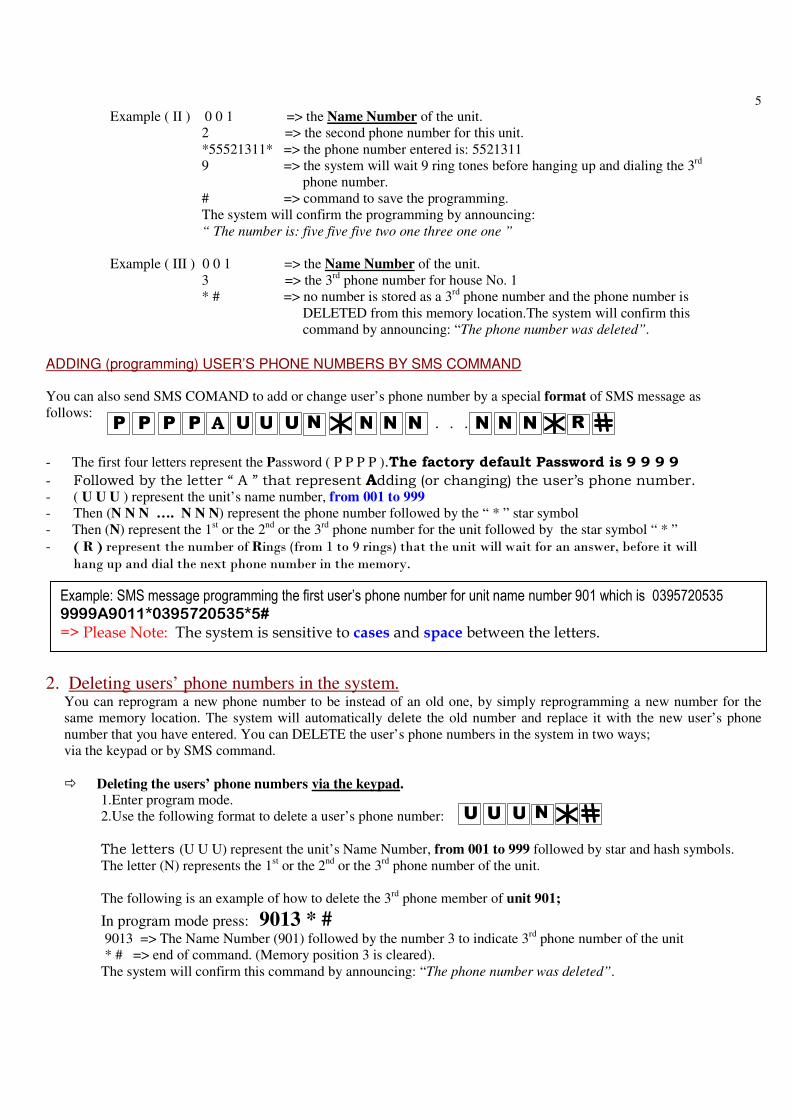
Example ( I ) 0 0 1 => the Name Number of the unit.
1 => indicating the first phone number to be stored for this unit.
*95720535* => the phone number stored as a first number is: 95720535
5 => number of ring tones the system should wait before hanging up
# => command to save the programming.
The system will confirm the programming by announcing:
“The number is: Nine five seven two zero five three five”
0
U NUU P PP PPP R. ..
5
UUU N
Example ( II ) 0 0 1 => the Name Number of the unit.
2 => the second phone number for this unit.
*55521311* => the phone number entered is: 5521311
9 => the system will wait 9 ring tones before hanging up and dialing the 3rd
phone number.
# => command to save the programming.
The system will confirm the programming by announcing:
“ The number is: five five five two one three one one ”
Example ( III ) 0 0 1 => the Name Number of the unit.
3 => the 3rd
phone number for house No. 1
* # => no number is stored as a 3rd
phone number and the phone number is
DELETED from this memory location.The system will confirm this
command by announcing: “The phone number was deleted”.
ADDING (programming) USER’S PHONE NUMBERS BY SMS COMMAND
You can also send SMS COMAND to add or change user’s phone number by a special format of SMS message as
follows:
- The first four letters represent the Password ( P P P P ).The factory default Password is 9 9 9 9
- Followed by the letter “ A ” that represent Adding (or changing) the user’s phone number. - ( U U U ) represent the unit’s name number, from 001 to 999
- Then (N N N …. N N N) represent the phone number followed by the “ * ” star symbol - Then (N) represent the 1
st or the 2
nd or the 3
rd phone number for the unit followed by the star symbol “ * ”
- ( R ) represent the number of Rings (from 1 to 9 rings) that the unit will wait for an answer, before it will hang up and dial the next phone number in the memory.
2. Deleting users’ phone numbers in the system. You can reprogram a new phone number to be instead of an old one, by simply reprogramming a new number for the
same memory location. The system will automatically delete the old number and replace it with the new user’s phone
number that you have entered. You can DELETE the user’s phone numbers in the system in two ways;
via the keypad or by SMS command.
� Deleting the users’ phone numbers via the keypad. 1.Enter program mode.
2.Use the following format to delete a user’s phone number:
The letters (U U U) represent the unit’s Name Number, from 001 to 999 followed by star and hash symbols.
The letter (N) represents the 1st or the 2
nd or the 3
rd phone number of the unit.
The following is an example of how to delete the 3rd
phone member of unit 901;
In program mode press: 9013 * #
9013 => The Name Number (901) followed by the number 3 to indicate 3rd
phone number of the unit
* # => end of command. (Memory position 3 is cleared).
The system will confirm this command by announcing: “The phone number was deleted”.
Example: SMS message programming the first user’s phone number for unit name number 901 which is 0395720535 9999A9011*0395720535*5#
=> Please Note: The system is sensitive to cases and space between the letters.
UUU N NN NNN. ..P PP P A RN

6
70
70
Please Note!
You can send one SMS message that includes more than one command to add or delete numbers by using the
COMMA mark ( “, “ ) between the commands. See examples of SMS messages below:
The following SMS message is an example of reprogramming (adding) the 1st
phone number (which is 0417 358 532)
for unit 901 and also adding the second phone number for unit 14 (which is 0418 565 578) and deleting the 3rd
phone number of unit 100 in the system.
9999A9011*0417358532*5#,A0142*0418 565 578*5#,D1003#
800
� Deleting the users’ phone numbers by SMS command. You can also send SMS COMAND to DELETE user’s phone numbers as follows:
The configuration of the SMS message below, would Delete the user’s phone number:
- The first four letters represent the Password ( P P P P ). The factory default Password is 9 9 9 9
- Followed by the latter “ D ” that represent Deleting a user phone number. - Then (U U U) represent the unit’s Name Number, from 001 to 999.
- The letter ( N ) represent the 1st or the 2
nd or the 3
rd phone number of the unit followed by the # symbol.
� How to Delete ALL the users’ phone numbers You can delete all the users’ phone numbers via the keypad ONLY (and not by SMS command) as follows:
1. Enter program mode.
2. Press and then press and hold the # key until you hear a long “Beep”.
3. Press to confirm within 10 seconds otherwise the system will exist this mode.
4. The system will confirm by announcing: “ Deleted “.
3. SMS confirmation service by the unit The unit will reply to any SMS message only if the password was correct.
The unit will reply by SMS message to the sender to inform if the command was confirmed or failed.
The factory default setting is that the unit does send a confirmation SMS messages.
� How to Cancel or Activate the SMS service in the unit You can Cancel or Activate the SMS service of the unit via the keypad or by SMS command as follows:
� Via the keypad
1. Enter program mode. 2. Use the following command to cancel the SMS service; The unit will confirm the command by a Long Beep.
Or 3. Use the following command to activate the SMS service;
The unit will confirm the command by a Long Beep.
Example of SMS message DELETING the first phone number of unit 901: 9999D9011#
=> Please Note: The system is sensitive to cases and space between the letters.

7
N0 1
NP PP P 0 1
� By SMS Command
You can Cancel or Activate the SMS service by sending SMS command to the unit as follows:
To cancel; send SMS
To Activate; send SMS
PPPP represent the four digit password.
The unit will reply by SMS as follows:
“SMS service was canceled” or “SMS service was activated”
4. How to select the Relay for the PUSH BUTTON input. The Push Button Input can activate Relay-1 or Relay-2 OR BOTH according to the function that was chosen for the
relay. The factory default setting for the Push Button Input is to activate RELAY-1 according to the function chosen.
(The factory default is a 4 second PULSE). You can change this setting via the keypad or by SMS command.
You can choose which RELAY the PUSH BUTTON INPUT activates by using the keypad, as follows:
1. Enter program mode.
2. Use the following format to make your selection The letter “ N “ represents the numbers 1or 2 for Relay-1 or Relay-2 or the number 3 to activate both relays.
BY SMS command:
The unit will reply by SMS message to the sender accordingly to the command send, to confirm or to say failed.
5. How to choose the Relays’ function
For each one of the relays 1 and 2 you can choose one of the following two functions;
MOMENTARY (PULSE) or LATCH function.
The factory default setting for both the relays is a MOMENTARY function (with a 4 second PULSE time).
You can change this setting via the keypad as follows: In program mode you can select and choose the relay’s function as follows:
The letter “ N “ represent the Number 1 or 2 for Relay-1 or Relay-2.
The letter “ F “ represent FUNCTION, 1 for Momentary or 2 for Latch.
BY SMS command:
The system will send a confirmation SMS message to the sender that says:
PPPP**02*NF# CONFIRMED or PPPP*02NF# FAILED
FN P PP P 0 2

8
TN0 5
TNP PP P 0 5
TNP PP P 0 5
1N0 3
2N0 3
6. How to set the Relays’ PULSE time interval For each one of the relays 1 or 2 you can choose the time interval of the pulse if a momentary function was selected.
The factory default setting for both the relays is a 5 second PULSE time.
You can change this setting via the keypad by entering program mode.
Set the pulse TIME interval for each one of the relays as follows:
The letter “ N “ represent the Number 1 or 2 for Relay-1 or Relay-2.
The letter “ T “ represent the PULSE time according to the list below:
Enter: 0 => for ½ second pulse time. Enter: 1 => for 1 second pulse time.
Enter: 2 => for 2 second pulse time.
Enter: 3 => for 5 second pulse time. Default.
Enter: 4 => for 10 second pulse time.
Enter: 5 => for 20 second pulse time.
Enter: 6 => for 45 second pulse time.
Enter: 7 => for 60 second pulse time.
Enter: 8 => for 90 second pulse time.
Enter: 9 => for 120 Seconds pulse time.
=> The system will confirm the chosen interval time by a Beep sound as long as the chosen Time.
i.e., if the time selected was 7 seconds, then the buzzer will sound for 7 seconds long “Beep”.
Setting the timers
BY SMS command:
The system would send a confirmation SMS message to the sender that says:
CONFIRMED
7. HOLD Command The user can send SMS command or use the keypad to overtake control of the relays and keep them active
(ON) until cancelation command is received by SMS or via the front keypad.
When the unit is programmed to Overtake Control of the system, the relays of the unit will not function to any
other commands by mobile phones or by the keypad until cancelation command is received.
To active or cancel HOLD COMMAND by the keypad
Enter program mode, and use the keypad as follows:
To activate press
To cancel press
While “ N “ can be “ 1” or “ 2 ” for relay one or relay two, and if “ 3 “ is chosen, than for both replays.
The unit will confirm by a long Beep.
Please Note! While hold command is active, the unit will announce ““Hold Command is Active””
to any attempt of activation of the relays by the keypad or a phone call.

9
P PP P
1N0 3
2N0 3
P PP P
TT0 4
P PP P TT0 4
By SMS Command To activate / cancel the “HOLD Command” by SMS you need to send SMS message as follows:
To Activate the HOLD command by SMS
To Cancel the HOLD command by SMS
- PPPP represent the 4 digit PASSWORD.
- The letter “ N ” represent relay 1 or relay 2 or 3 for both relays.
The system will send an SMS to the sender informing bout the “Hold Command” of both relays for each
SMS command being sent, as follows: “Confirming Relay 1 is Active ON”
“Confirming Relay 2 is No Longer Hold Active”.
� You can send one SMS to activate the Hold commands for both the relays as follows: 9999**03*31#
The SMS replay from the system is: “Confirming relay1 and relay 2 are ON Hold Active”
� You can send one SMS to cancel the Hold commands for both the relays as follows: 9999**03*32#
The SMS replay from the system i: “Confirming relay1 and relay 2 are No Longer Hold Active”
8. How to limit the Talking Time In program mode you can select and limit the talking time of the visitor.
The factory default limit time is 55 second.
The system will end each call (after the chosen “Talking Time”) by an announcement: “ END OF CALL” .
Use the keypad and enter program mode and set the required talking time required as follows:
The letters “ T T “ represent the time in seconds according to the table below:
Enter: 0 0 => for Zero talking time.
Enter: 5 0 => for 50 seconds talking time (Default)
Enter: 6 1 => for 1 Minute talking time
Enter: 6 2 => for 2 Minutes talking time
Enter: 6 3 => for 3 Minutes talking time
;
Enter: 6 9 => for 9 Minutes talking time
Enter: 7 0 => for 10 Minutes talking time
Enter: 9 9 => for unlimited talking time.
The unit will confirm by Long Beep.
By SMS Command
To change the talking time by SMS command, send the SMS as follows:
The unit will confirm by SMS message to the sender as follows: “The talking time was changed“

10
P PP P TT0 4
N0 6
P PP P N0 6
TT0 4
8. How to limit the Talking Time The factory default talking time is limited to 55 second.
You can change the talking time of the visitor by entering program mode and press:
While the letters “ T T “ represent the time in seconds according to the table below:
Enter: 0 0 => for Zero talking time.
;
Enter: 5 9 => for 55 seconds talking time (Default)
Enter: 6 1 => for 1 Minute talking time
Enter: 6 2 => for 2 Minutes talking time
Enter: 6 3 => for 3 Minutes talking time
;
Enter: 6 9 => for 9 Minutes talking time
Enter: 7 0 => for 10 Minutes talking time
Enter: 9 9 => for unlimited talking time.
The unit will confirm by Long Beep.
The system will end each call (after the chosen “Talking Time”) with an announcement: “ END OF CALL” .
By SMS Command
� To change the talking time by SMS command, send the SMS as follows:
The unit will confirm by SMS message to the sender as follows: “Confirming the talking time was changed“
9. How to LOCK and UNLOCK the unit The unit will not operate the outputs of the relays in LOCKED mode. The system will announce “wrong command” for any attempt to make a call or activate the relay outputs by a pin code via the keypad.
To lock & unlock the unit; In program mode you can lock and unlock the system with the following command:
The letter “ N ” represents “ 1 “ for LOCKING and “ 2 “ for UNLOCKING.
A long Beep will be heard to confirm.
By SMS Command
� To LOCK and UNLOCK the unit by SMS command, send the SMS as follows:
PPPP represent the 4-digit PASSWORD.
The letter “ N ” represent “ 1 “ for LOCK and “ 2 “ for UNLOCK.
The unit will confirm by SMS to the sender that says:
“ The system is locked” or “The system is unlocked “ accordingly.
11
1 1
1 1P PP P
1 2
1 2P PP P
N1 3
N1 3P PP P
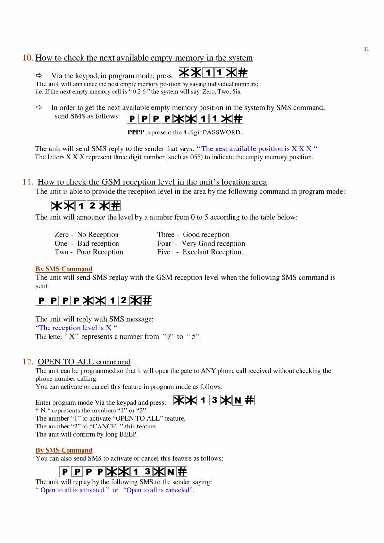
10. How to check the next available empty memory in the system
� Via the keypad, in program mode, press The unit will announce the next empty memory position by saying individual numbers;
i.e. If the next empty memory cell is “ 0 2 6 ” the system will say: Zero, Two, Six
� In order to get the next available empty memory position in the system by SMS command,
send SMS as follows:
PPPP represent the 4 digit PASSWORD.
The unit will send SMS reply to the sender that says: “ The nest available position is X X X “ The letters X X X represent three digit number (such as 055) to indicate the empty memory position.
11. How to check the GSM reception level in the unit’s location area The unit is able to provide the reception level in the area by the following command in program mode:
The unit will announce the level by a number from 0 to 5 according to the table below:
Zero - No Reception
One - Bad reception
Two - Poor Reception
Three - Good reception
Four - Very Good reception
Five - Excelant Reception.
By SMS Command
The unit will send SMS replay with the GSM reception level when the following SMS command is
sent:
The unit will reply with SMS message:
“The reception level is X “
The letter “ X” represents a number from “0“ to “ 5“.
12. OPEN TO ALL command The unit can be programmed so that it will open the gate to ANY phone call received without checking the
phone number calling.
You can activate or cancel this feature in program mode as follows:
Enter program mode Via the keypad and press:
“ N “ represents the numbers “1” or “2”
The number “1” to activate “OPEN TO ALL” feature.
The number “2” to “CANCEL” this feature.
The unit will confirm by long BEEP.
By SMS Command You can also send SMS to activate or cancel this feature as follows:
The unit will replay by the following SMS to the sender saying:
“ Open to all is activated ” or “Open to all is canceled”.

12
P PP P C CC CNUUU
P PP P C CC CUUU
13. How to change the PASSWORD The factory default password is 9999.
You can change the password in program mode as follows:
The letters P P P P represent the old password and the letters W W W W represent the new password.
The unit will confirm the new password by announcing: “The number is ….”
By SMS Command For changing the password by SMS command, send the following message:
The unit will reply by SMS: The new password is X X X X
(B) Setting the Keypad Access Control The keypad can store up to 999 different pin codes for up to 999 users.
The pin codes can be set for each user in Program Mode (PM).
1. How to set the pin code for each user You can program the pin codes via the keypad or by sending SMS command.
Via the keypad a. Enter program mode.
b. The following letters and configuration represent the sequence for programming the pin code numbers:
- The first three digits ( U U U ) represent the user number. From 001 to 999.
- ( N ) represents (1, 2 or 3 ) relay 1 or relay 2 or 3 for both relays to be linked to this user.
- ( * C C C C ) the pin code number entered for this specific user.
- ( # ) Enter the information into the system.
The system will announce the pin code as a confirmation: “ The pin code is …”
Note: The system allows the same pin code for many users. i.e., user No.1 and user No.8 can have the same pin code.
By SMS message:
- The first four letters ( P P P P ) represent password.
- ( * UUU* ) represent the user number (from 001 to 999)
- ( N) represent Relay 1 or relay 2 or 3 for both relays to be linked to this user.
- ( * C C C C # ) the pin code number entered for this specific user.
The unit will a send confirmation SMS to the sender
CONFIRMED
Or FAILED message as the example below:
FAILED

13
CC CC
NUUUP PP P
C CC CP PP P
C CC CP PP P
2. How to DELETE the pin code of a certain user There are three ways to delete the user’s pin code from the system:
1. By overwriting and entering a new pin code for the same user.
2. By deleting the pin code using the user’s location number in the memory.
3. Or using the user’s pin code to delete it from the system.
Warning ! Since the system allows the same pin code for many users, all users’ that had the same pin code will have their
pin code deleted in case this pin code was deleted from the system.
(1) Deleting the Pin Code by entering a new pin code, see section B-1.
(2) Deleting the Pin Code of a certain known user;
In program mode;
Enter the user’s number (from 001 to 999) followed by the RELAY number that this user is linked to and
then the star key followed by hash.
In this case the system will announce: “The pin code was deleted “
The following example shows how the pin code of the 875th user in system was deleted for relay 2.
The system will announce: “The pin code was deleted “
By SMS message:
- The first four letters ( P P P P ) represent password.
- ( * UUU* ) represent the user number (from 001 to 999)
- ( N) represents Relay 1 or relay 2 ( or 3 for both relays) that is linked to this user.
- ( * # ) to confirm this command.
The unit will reply and send a confirmation SMS to the sender as follows:
CONFIRMED
(3) Deleting a certain Pin Code from the system;
In program mode,
You can delete a certain known pin code from the system without the need of the users’ numbers.
The system will announce: “The pin code was deleted “
Note! The system will delete this pin code for all the users that had the same pin code.
By SMS message:
C C C C : represents the pin code number entered.
The unit will send a confirmation SMS to the sender as follows:
CONFIRMED

14
1 5P PP P 1 5P PP P,
(4) How to DELETE all pin codes of all the users
In program mode, press
The letters P P P P represent the password,
You must press and hold the hash key # at the end of the command for three seconds until you hear the system
say: “The pin code was deleted “
By SMS message: To DELETE all pin codes of all the users by SMS command, send the following message:
(C) How to set the unit to FACTORY DEFUALT settings There are two ways to set the units to factory settings, by the keypad or by SMS command.
1. By keypad
Enter **00*# and press and hold the # key for 3 seconds till you hear a long beep.
Enter **00*# once again (within 10 seconds) and the unit will respond with a long beep and announce
“Delete” after 10 seconds. If you do not enter **00*# the second time within 10 seconds, the unit will
disregard the command and exit that mode.
2. By SMS:
Send SMS command as follows: PPPP**00*#,PPPP**00*#
The system will send back SMS message as: PPPP**00*#, PPPP**00*# CONFIRMED.
©All Rights Reserved to
ECA Electronic Engineering Pty. LTD.
AUSTRALIA Tel: +61 3 95720535
www.gatesonsolar.com
Warning ! Setting the unit to FACTORY DEFALT will delete all phone numbers,
pin-codes and set all the parameters of the unit to the factory Settings.
Related Documents