Easy Builder 500 제 6 제 제 제제 PLC 제 제제 1. MT 500 (1) 프프프 (25 Pin D female) 1 STB OUT 8 DATA6 OUT 2 DATA0 OUT 9 DATA7 OUT 3 DATA1 OUT 11 BUSY IN 4 DATA2 OUT 15 ERROR IN 5 DATA3 OUT 16 INIT OUT 6 DATA4 OUT 17- 25 GND 7 DATA5 OUT (2) PC [RS-232] & PLC [RS485] (9Pin D male프) PC [RS-232] PLC [RS-485] (3) PLC [RS-232] (9Pin D female프) PLC [RS-232] 2 SD (TXD) OUT 3 RD (RXD) IN 5 GND 7 CS (CTS) IN 8 RS (RTS) OUT 105 7 SD(TXD) OUT 8 RD(RXD) IN 5 GND 1 RX- IN 2 RX+ IN 3 TX- OUT 4 TX+ OUT 5 GND

Welcome message from author
This document is posted to help you gain knowledge. Please leave a comment to let me know what you think about it! Share it to your friends and learn new things together.
Transcript
Easy Builder 500
제 6 장 각 社의 PLC 와 연결 1. MT 500 (1) 프린터 (25 Pin D female)
1 STB OUT 8 DATA6 OUT
2 DATA0 OUT 9 DATA7 OUT
3 DATA1 OUT 11 BUSY
IN
4 DATA2 OUT 15 ERROR IN
5 DATA3 OUT 16 INIT OUT
6 DATA4 OUT 17-25
GND7 DATA5 OUT
(2) PC [RS-232] & PLC [RS485] (9Pin D male형) PC [RS-232] PLC [RS-485]
(3) PLC [RS-232] (9Pin D female형) PLC [RS-232]
2 SD (TXD) OUT
3RD
(RXD) IN
5 GND
7 CS (CTS) IN
8 RS (RTS) OUT
105
7 SD(TXD) OUT
8RD(RXD
) IN5 GND
1 RX- IN2 RX+ IN3 TX- OUT4 TX+ OUT5 GND

Easy Builder 500
(4) MT5-PCCAB ( CABLE 별도로 구매, MT5-PCCAB의 길이는 약2M)
MTS-PCCAB는 ON-Line Simulation 때, CABLE을 이용하여 이미 완성된 MT Data 또는
PC를 이용하여 MT 통신과 PLC연결 CABLE을 이용합니다. 이에 PC에서 MT와 PLC의 작업을 Online-Simulator 합니다. MT와 PLC의 연결은 각 PLC 결선도를 참고 바랍니다.
(5) 작화전송 CABLE (MT5-PC)
PC MT500 PLC [RS-232]9P D-SUB Female 9P D-SUB Female
2 RXD 7 TXD
3 TXD 8 RXD5 GND 5 GND
이 CABLE을 이용하여 미리 작화 된 DATA를 전송합니다.
106
PC
PLC
HMI
MT5-PCCAB PLC 연결
PLC
MT5-PC
PC HMI
Easy Builder 500
2. Mitsubishi FX0n/2Mitsubishi FX0s/FX0n/FX1s/FX1n/FX2 PLCHMI Setting:Parameters Recommend Option NotesPLC type Mitsubishi
FX0n/FX2Mitsubishi FX0n/FX2
Com port RS422 RS232/RS422Baud rate 9600 9600/~/115200 PLC설정과 일치시킴
Parity bit Even Even, Odd, None PLC설정과 일치시킴
Data Bits 7 7,8 PLC설정과 일치시킴
Stop Bits 1 1,2 PLC설정과 일치시킴
HMI Station No. 0 0~255PLC Station No. 0 0~255 PLC설정과 일치시킴
PLC Setting:Communication mode 9600, Even , 7, 1
Wiring diagram:MT500 PLC [RS-485] Mitsubishi FX series PLC CPU
RS422 Port9P D-SUB Female 8P MiniDin Male
1 RX- 4 TX-
2 RX+ 7 TX+3 TX- 1 RX-4 TX+ 2 RX+
5 GND 3 GND
107
8Pin miniDinFemale
Easy Builder 500
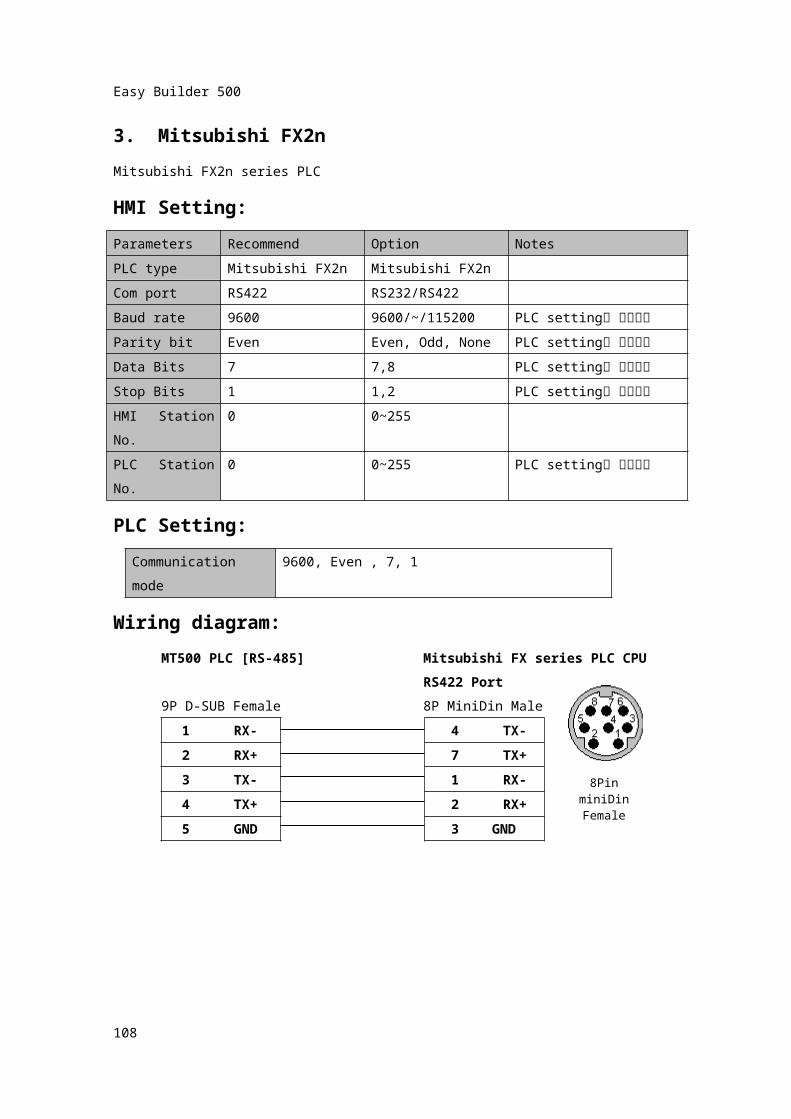
3. Mitsubishi FX2nMitsubishi FX2n series PLCHMI Setting:Parameters Recommend Option NotesPLC type Mitsubishi FX2n Mitsubishi FX2nCom port RS422 RS232/RS422Baud rate 9600 9600/~/115200 PLC setting과 일치시킴
Parity bit Even Even, Odd, None PLC setting과 일치시킴
Data Bits 7 7,8 PLC setting과 일치시킴
Stop Bits 1 1,2 PLC setting과 일치시킴
HMI Station No.
0 0~255
PLC Station No.
0 0~255 PLC setting과 일치시킴
PLC Setting:Communication mode
9600, Even , 7, 1
Wiring diagram:MT500 PLC [RS-485] Mitsubishi FX series PLC CPU
RS422 Port9P D-SUB Female 8P MiniDin Male
1 RX- 4 TX-
2 RX+ 7 TX+3 TX- 1 RX-
4 TX+ 2 RX+5 GND 3 GND
108
8Pin miniDinFemale
Easy Builder 500
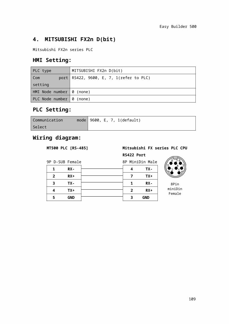
4. MITSUBISHI FX2n D(bit)Mitsubishi FX2n series PLCHMI Setting:PLC type MITSUBISHI FX2n D(bit)Com port setting RS422, 9600, E, 7, 1(refer to PLC)HMI Node number 0 (none)PLC Node number 0 (none)PLC Setting:Communication mode Select
9600, E, 7, 1(default)
Wiring diagram:MT500 PLC [RS-485] Mitsubishi FX series PLC CPU
RS422 Port9P D-SUB Female 8P MiniDin Male
1 RX- 4 TX-
2 RX+ 7 TX+3 TX- 1 RX-
4 TX+ 2 RX+5 GND 3 GND
109
8Pin miniDinFemale
Easy Builder 500
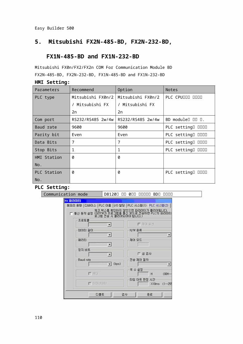
5. Mitsubishi FX2N-485-BD, FX2N-232-BD, FX1N-485-BD and FX1N-232-BD
Mitsubishi FX0n/FX2/FX2n COM For Communication Module BDFX2N-485-BD, FX2N-232-BD, FX1N-485-BD and FX1N-232-BDHMI Setting:Parameters Recommend Option NotesPLC type Mitsubishi FX0n/2
/ Mitsubishi FX 2nMitsubishi FX0n/2/ Mitsubishi FX 2n
PLC CPU기종과 일치시킴
Com portRS232/RS485 2w/4w
RS232/RS485 2w/4wBD module에 맞출 것.
Baud rate 9600 9600 PLC setting과 일치시킴
Parity bit Even Even PLC setting과 일치시킴
Data Bits 7 7 PLC setting과 일치시킴
Stop Bits 1 1 PLC setting과 일치시킴
HMI Station No. 0 0PLC Station No. 0 0 PLC setting과 일치시킴
PLC Setting:
FX2N-485-BD, FX1N-485-BD, FX2N-232-BD, FX1N-232-BD
110
Communication mode D8120의 값이 0으로 되어있어야 BD로 통신가능

Easy Builder 500
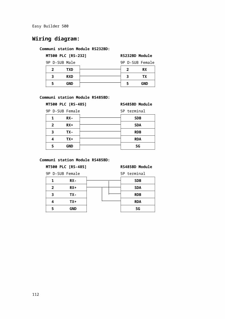
Wiring diagram:Communi station Module RS232BD:
MT500 PLC [RS-232] RS232BD Module9P D-SUB Male 9P D-SUB Female
2 TXD 2 RX
3 RXD 3 TX5 GND 5 GND
Communi station Module RS485BD:MT500 PLC [RS-485] RS485BD Module9P D-SUB Female 5P terminal
1 RX- SDB
2 RX+ SDA3 TX- RDB4 TX+ RDA5 GND SG
Communi station Module RS485BD:MT500 PLC [RS-485] RS485BD Module9P D-SUB Female 5P terminal
1 RX-
SDB
2 RX+ SDA3 TX- RDB4 TX+ RDA5 GND SG
111
Easy Builder 500
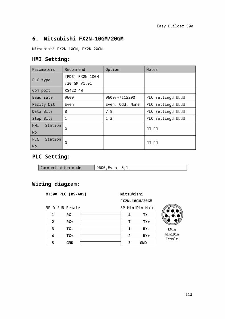
6. Mitsubishi FX2N-10GM/20GMMitsubishi FX2N-10GM, FX2N-20GM.HMI Setting:Parameters Recommend Option Notes
PLC type[PDS] FX2N-10GM/20 GM V1.01
Com port RS422 4WBaud rate 9600 9600/~/115200 PLC setting과 일치시킴
Parity bit Even Even, Odd, None PLC setting과 일치시킴
Data Bits 8 7,8 PLC setting과 일치시킴
Stop Bits 1 1,2 PLC setting과 일치시킴
HMI Station No.
0 설정 없음.
PLC Station No.
0 설정 없음.
PLC Setting: Wiring diagram:
MT500 PLC [RS-485] MitsubishiFX2N-10GM/20GM
9P D-SUB Female 8P MiniDin Male1 RX- 4 TX-
2 RX+ 7 TX+3 TX- 1 RX-
4 TX+ 2 RX+5 GND 3 GND
112
Communication mode 9600,Even, 8,1
8Pin miniDinFemale
Easy Builder 500
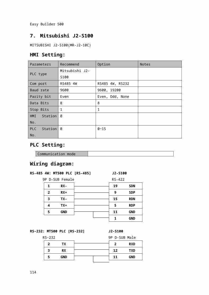
7. Mitsubishi J2-S100MITSUBISHI J2-S100(MR-J2-10C)HMI Setting:Parameters Recommend Option NotesPLC type Mitsubishi J2-S100Com port RS485 4W RS485 4W, RS232Baud rate 9600 9600, 19200Parity bit Even Even, Odd, NoneData Bits 8 8Stop Bits 1 1HMI Station No.
0
PLC Station No.
0 0~15
PLC Setting:
Wiring diagram:RS-485 4W: MT500 PLC [RS-485] J2-S100
9P D-SUB Female RS-4221 RX- 19 SDN
2 RX+ 9 SDP3 TX- 15 RDN4 TX+ 5 RDP5 GND 11 GND
1 GND
RS-232: MT500 PLC [RS-232] J2-S100RS-232 9P D-SUB Male
2 TX 2 RXD
113
Communication mode
Easy Builder 500
3 RX 12 TXD5 GND 11 GND
1 GND
114
Easy Builder 500
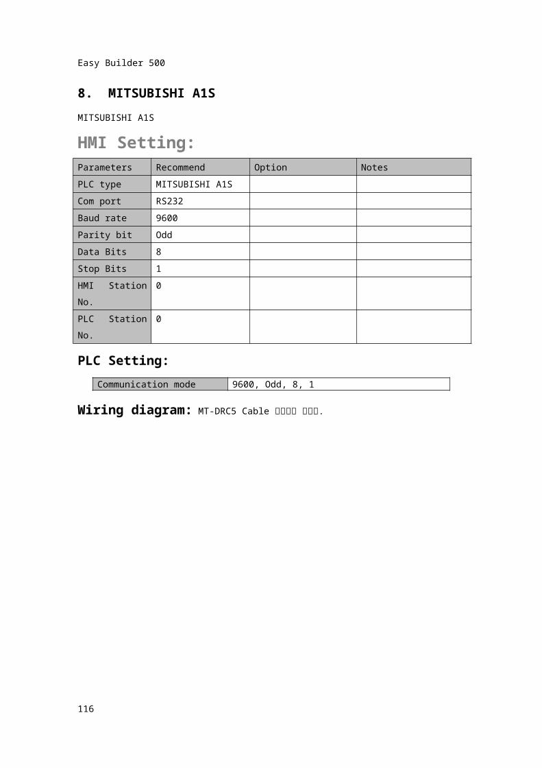
8. MITSUBISHI A1SMITSUBISHI A1S
HMI Setting:Parameters Recommend Option NotesPLC type MITSUBISHI A1SCom port RS232Baud rate 9600Parity bit OddData Bits 8Stop Bits 1HMI Station No.
0
PLC Station No.
0
PLC Setting:
Wiring diagram: MT-DRC5 Cable 사용하여 통신함.
115
Communication mode 9600, Odd, 8, 1
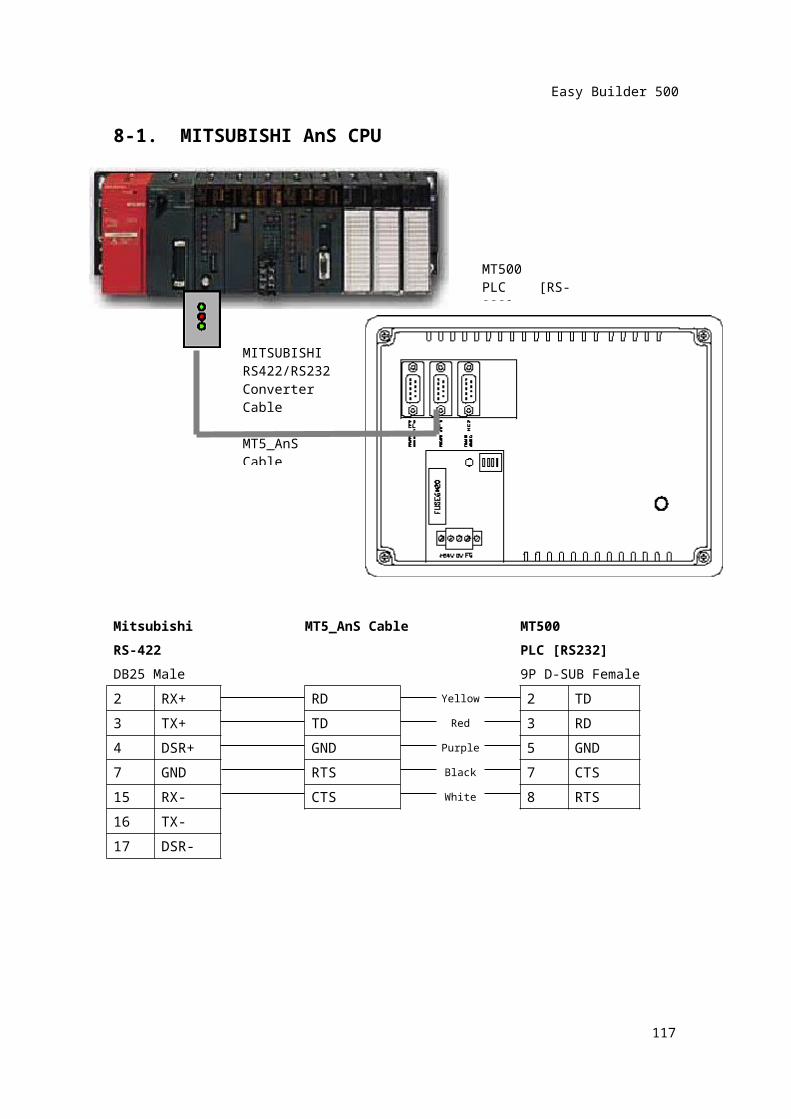
MITSUBISHIRS422/RS232Converter Cable
MT5_AnS Cable
Easy Builder 500
8-1. MITSUBISHI AnS CPU
Mitsubishi MT5_AnS Cable MT500RS-422 PLC [RS232]DB25 Male 9P D-SUB Female2 RX+ RD Yellow 2 TD
3 TX+ TD Red 3 RD4 DSR+ GND Purple 5 GND7 GND RTS Black 7 CTS15 RX- CTS White 8 RTS16 TX-17 DSR-
116
MT500PLC [RS-232]
Easy Builder 500
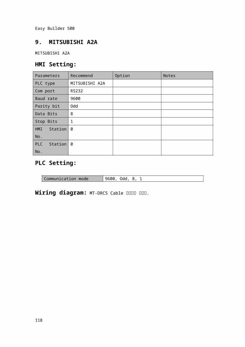
9. MITSUBISHI A2AMITSUBISHI A2AHMI Setting:Parameters Recommend Option NotesPLC type MITSUBISHI A2ACom port RS232Baud rate 9600Parity bit OddData Bits 8Stop Bits 1HMI Station No.
0
PLC Station No.
0
PLC Setting:
Wiring diagram: MT-DRC5 Cable 사용하여 통신함.
117
Communication mode 9600, Odd, 8, 1
Easy Builder 500
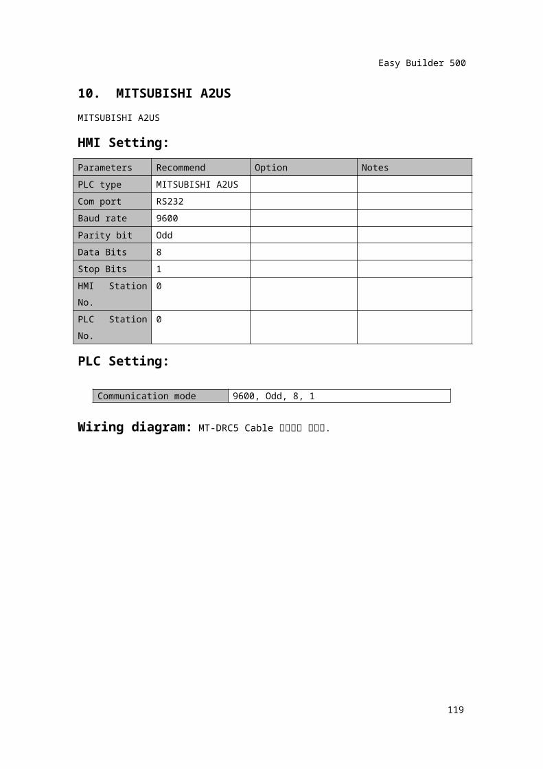
10. MITSUBISHI A2USMITSUBISHI A2USHMI Setting:Parameters Recommend Option NotesPLC type MITSUBISHI A2USCom port RS232Baud rate 9600Parity bit OddData Bits 8Stop Bits 1HMI Station No.
0
PLC Station No.
0
PLC Setting:
Wiring diagram: MT-DRC5 Cable 사용하여 통신함.
118
Communication mode 9600, Odd, 8, 1
Easy Builder 500
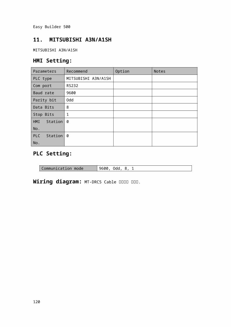
11. MITSUBISHI A3N/A1SHMITSUBISHI A3N/A1SHHMI Setting:Parameters Recommend Option NotesPLC type MITSUBISHI A3N/A1SHCom port RS232Baud rate 9600Parity bit OddData Bits 8Stop Bits 1HMI Station No.
0
PLC Station No.
0
PLC Setting:
Wiring diagram: MT-DRC5 Cable 사용하여 통신함.
119
Communication mode 9600, Odd, 8, 1
Easy Builder 500
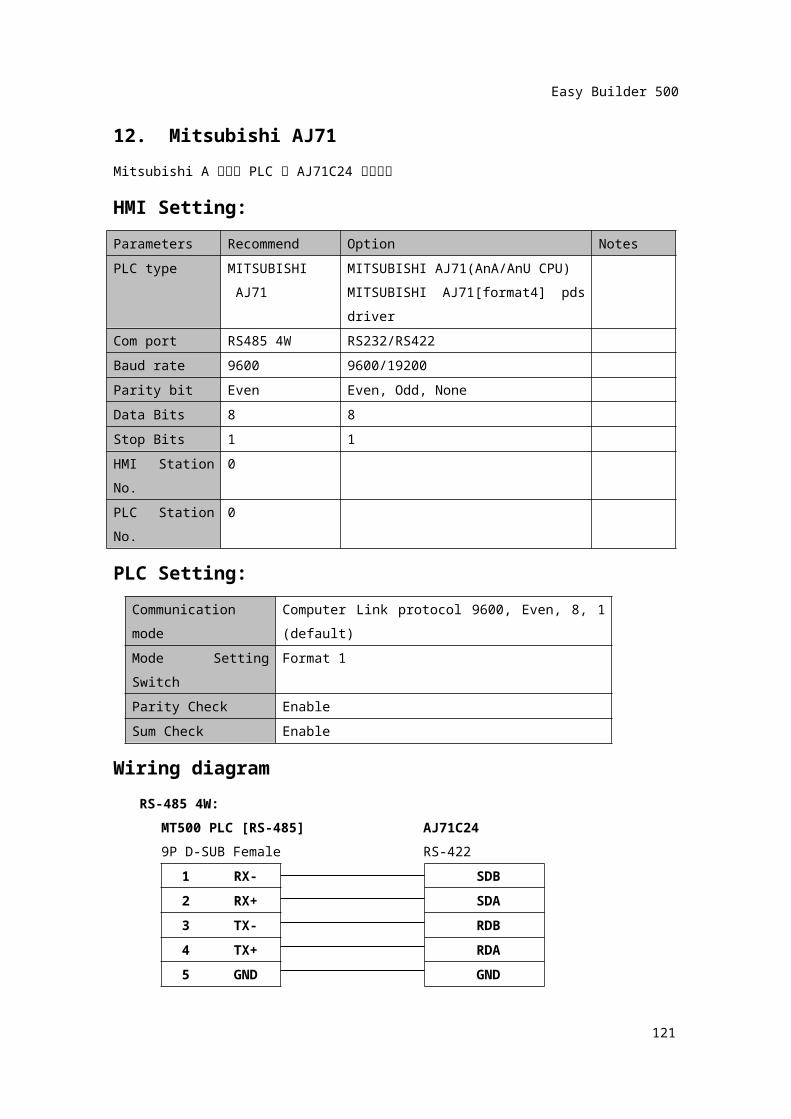
12. Mitsubishi AJ71Mitsubishi A 시리즈 PLC 의 AJ71C24 통신카드
HMI Setting:Parameters Recommend Option NotesPLC type MITSUBISHI
AJ71MITSUBISHI AJ71(AnA/AnU CPU)MITSUBISHI AJ71[format4] pds driver
Com port RS485 4W RS232/RS422Baud rate 9600 9600/19200Parity bit Even Even, Odd, NoneData Bits 8 8Stop Bits 1 1HMI Station No.
0
PLC Station No.
0
PLC Setting:Communication mode
Computer Link protocol 9600, Even, 8, 1 (default)
Mode Setting Switch Format 1Parity Check EnableSum Check Enable
Wiring diagramRS-485 4W:
MT500 PLC [RS-485] AJ71C249P D-SUB Female RS-422
1 RX- SDB
2 RX+ SDA3 TX- RDB4 TX+ RDA5 GND GND
120
Easy Builder 500
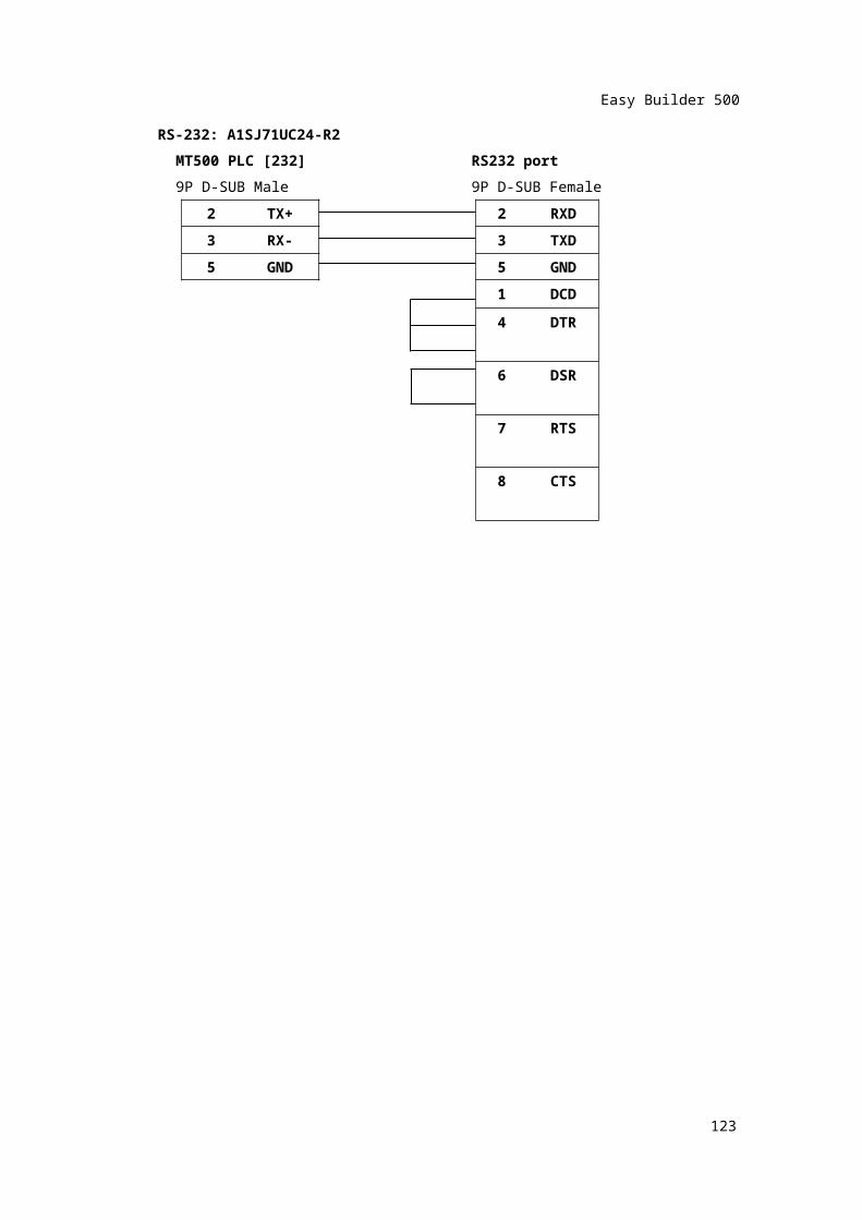
RS-232: A1SJ71UC24-R2MT500 PLC [232] RS232 port9P D-SUB Male 9P D-SUB Female
2 TX+ 2 RXD
3 RX- 3 TXD5 GND 5 GND
1 DCD4 DTR6 DSR7 RTS8 CTS
121

Easy Builder 500
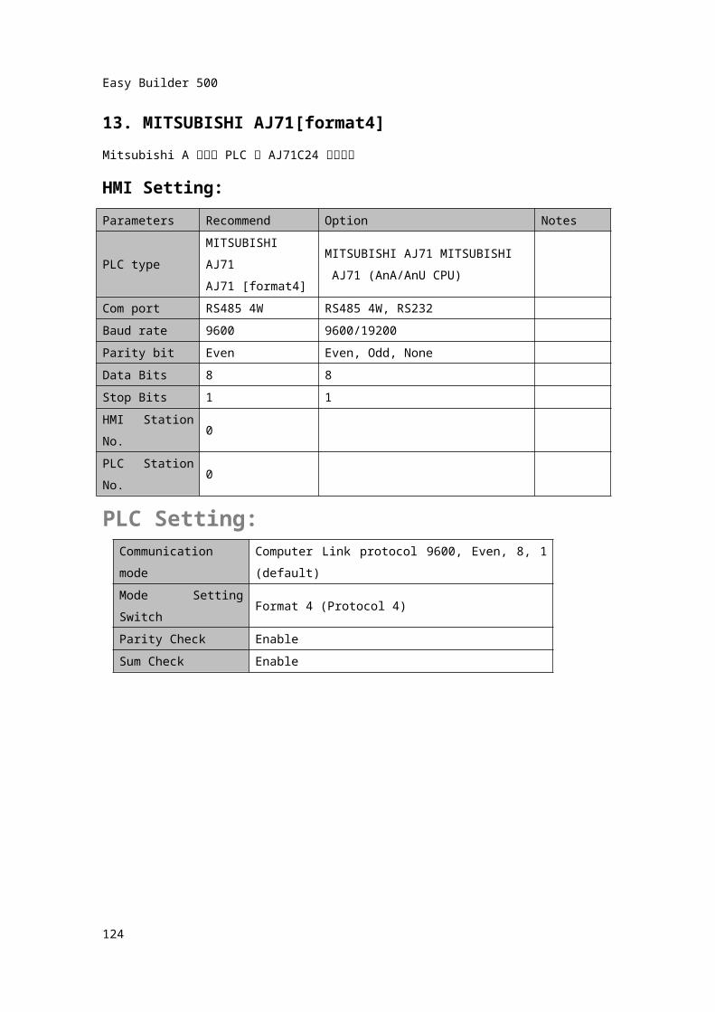
13. MITSUBISHI AJ71[format4]Mitsubishi A 시리즈 PLC 의 AJ71C24 통신카드
HMI Setting:Parameters Recommend Option Notes
PLC typeMITSUBISHI AJ71AJ71 [format4]
MITSUBISHI AJ71 MITSUBISHI AJ71 (AnA/AnU CPU)
Com port RS485 4W RS485 4W, RS232Baud rate 9600 9600/19200Parity bit Even Even, Odd, NoneData Bits 8 8Stop Bits 1 1HMI Station No.
0
PLC Station No.
0
PLC Setting:Communication mode
Computer Link protocol 9600, Even, 8, 1 (default)
Mode Setting Switch Format 4 (Protocol 4)Parity Check EnableSum Check Enable
122
Easy Builder 500
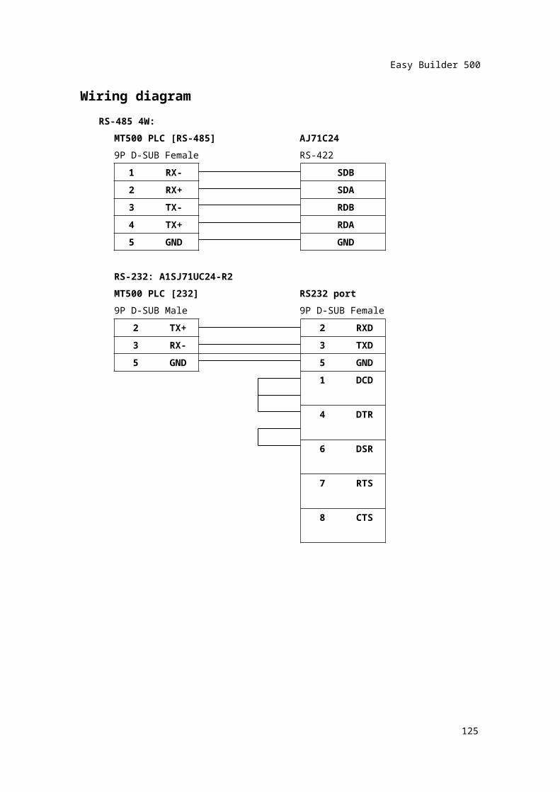
Wiring diagramRS-485 4W:
MT500 PLC [RS-485] AJ71C249P D-SUB Female RS-422
1 RX- SDB
2 RX+ SDA3 TX- RDB4 TX+ RDA5 GND GND
RS-232: A1SJ71UC24-R2MT500 PLC [232] RS232 port9P D-SUB Male 9P D-SUB Female
2 TX+ 2 RXD3 RX- 3 TXD
5 GND 5 GND1 DCD4 DTR6 DSR7 RTS8 CTS
123
Easy Builder 500
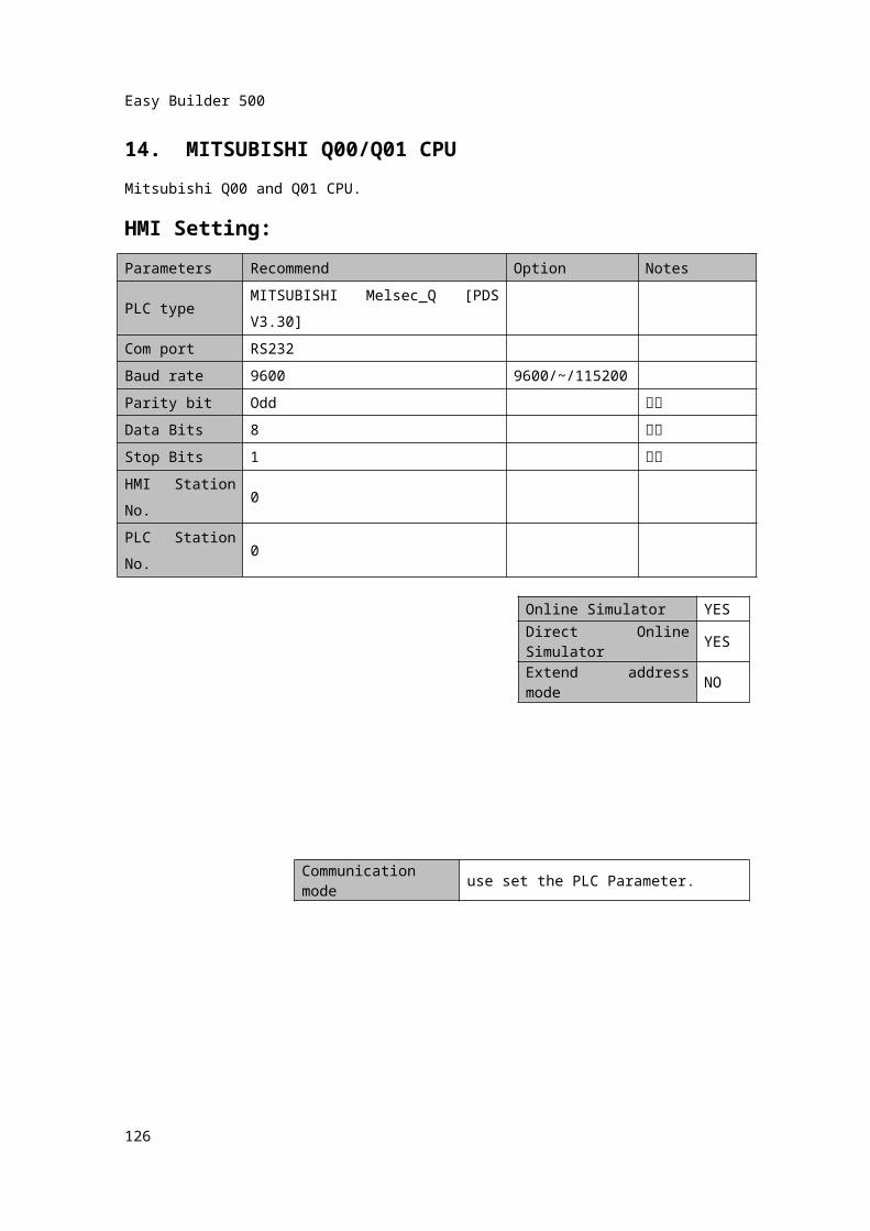
14. MITSUBISHI Q00/Q01 CPU Mitsubishi Q00 and Q01 CPU.HMI Setting:Parameters Recommend Option Notes
PLC typeMITSUBISHI Melsec_Q [PDS V3.30]
Com port RS232Baud rate 9600 9600/~/115200Parity bit Odd 고정
Data Bits 8 고정
Stop Bits 1 고정
HMI Station No.
0
PLC Station No.
0
124
Online Simulator YESDirect Online Simulator YESExtend address mode NO
Communication mode use set the PLC Parameter.
Easy Builder 500
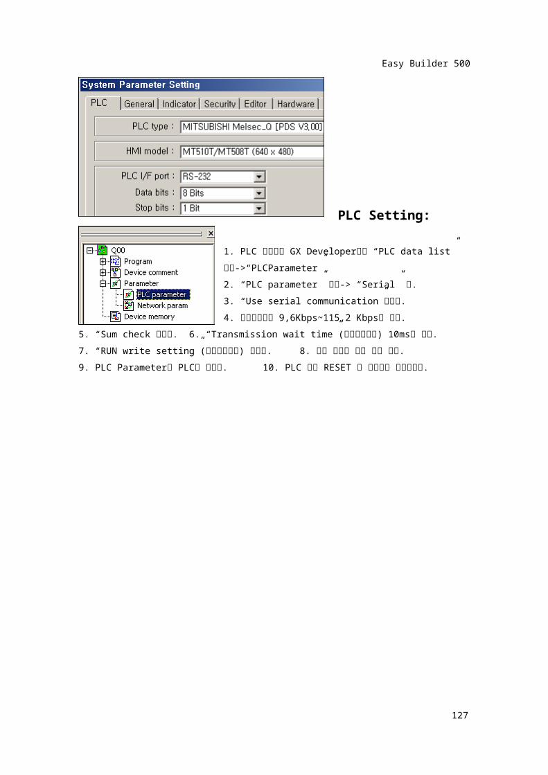
PLC Setting:
1. PLC 프로그램 GX Developer에서 “PLC data list” 선택->“PLCParameter”2. “PLC parameter” 선택-> “Serial” 탭.3. “Use serial communication”체크함.4. 통신속도설정 9,6Kbps~115,2 Kbps중 선택.
5. “Sum check”선택함. 6. “Transmission wait time”(전송지연시간) 10ms로 설정.7. “RUN write setting”(런중쓰기가능) 선택함. 8. 확인 버튼을 눌러 창을 닫음.9. PLC Parameter를 PLC에 쓰기함. 10. PLC 전원 RESET 후 파라메터 적용가능함.
125
Easy Builder 500
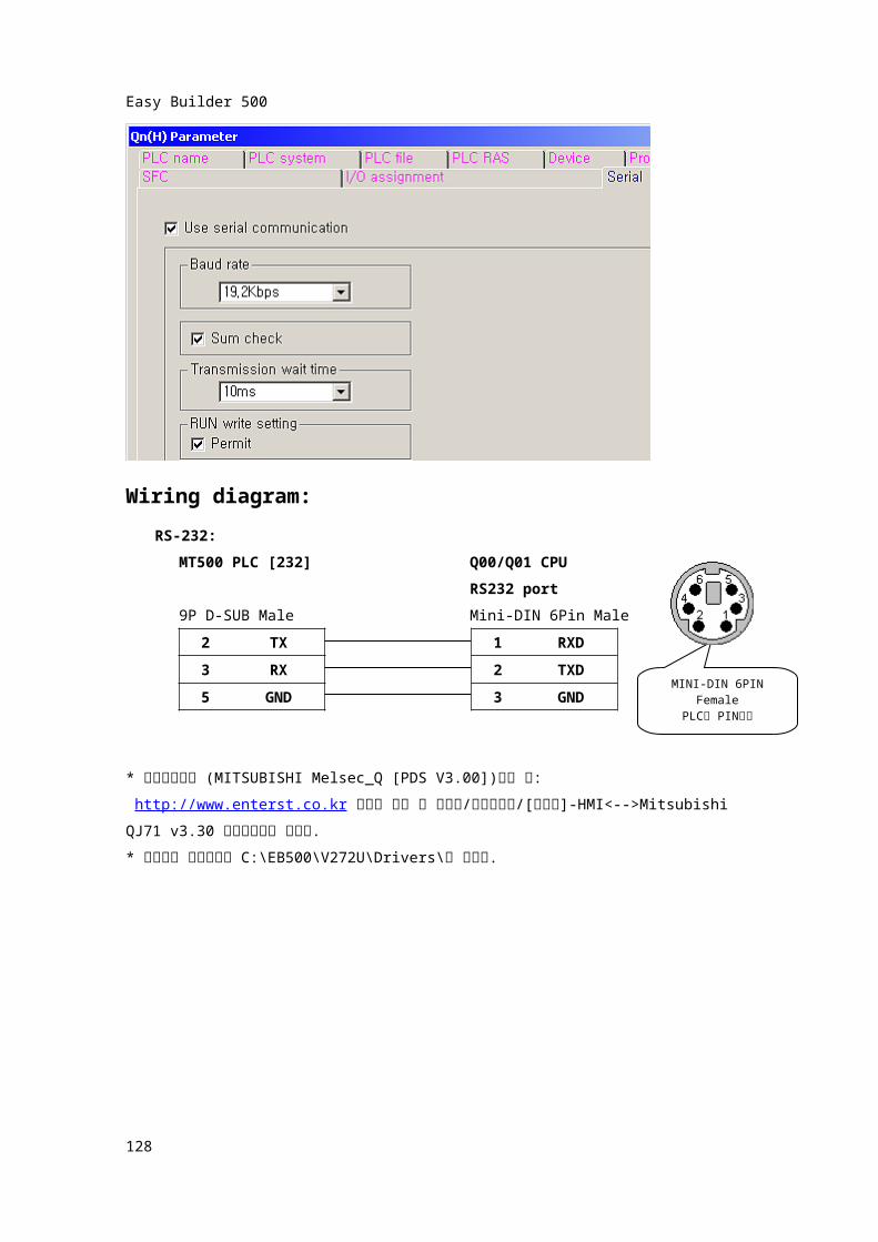
Wiring diagram:RS-232:
MT500 PLC [232] Q00/Q01 CPURS232 port
9P D-SUB Male Mini-DIN 6Pin Male
2 TX 1 RXD
3 RX 2TXD
5 GND 3 GND
* 통신드라이버 (MITSUBISHI Melsec_Q [PDS V3.00])받는 곳: http://www.enterst.co.kr 사이트 접속 후 자료실/소프트웨어/[이지뷰]-HMI<-->Mitsubishi QJ71 v3.30 통신프로토콜 선택함.* 다운받은 압축파일을 C:\EB500\V272U\Drivers\에 풀어줌.
126
MINI-DIN 6PIN Female
PLC측 PIN번호
Easy Builder 500
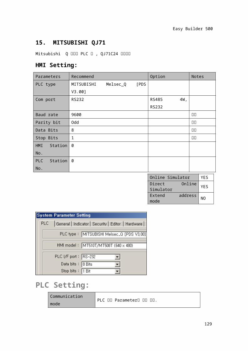
15. MITSUBISHI QJ71Mitsubishi Q 시리즈 PLC 의 , QJ71C24 통신카드
HMI Setting:Parameters Recommend Option NotesPLC type MITSUBISHI Melsec_Q [PDS V3.00]Com port RS232 RS485 4W,
RS232Baud rate 9600 고정
Parity bit Odd 고정
Data Bits 8 고정
Stop Bits 1 고정
HMI Station No.
0
PLC Station No.
0
PLC Setting:Communication mode
PLC 기본 Parameter로 설정 없음.
127
Online Simulator YESDirect Online Simulator YESExtend address mode NO
Easy Builder 500
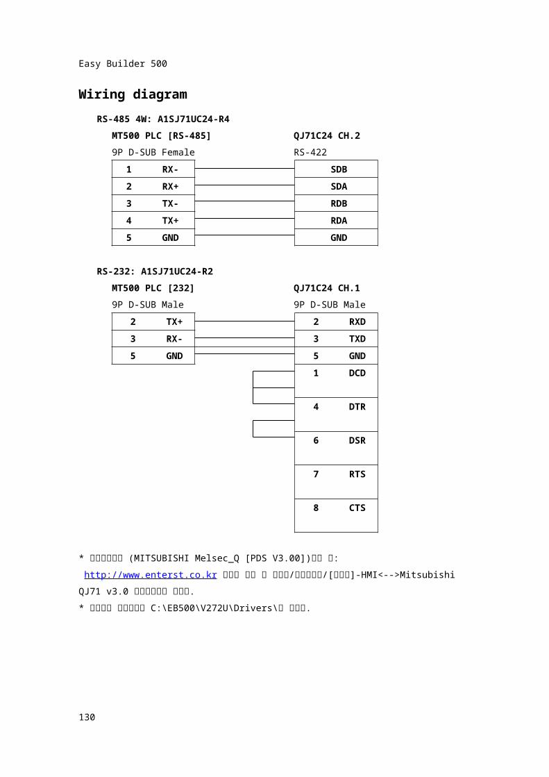
Wiring diagramRS-485 4W: A1SJ71UC24-R4
MT500 PLC [RS-485] QJ71C24 CH.29P D-SUB Female RS-422
1 RX- SDB
2 RX+ SDA3 TX- RDB4 TX+ RDA5 GND GND
RS-232: A1SJ71UC24-R2MT500 PLC [232] QJ71C24 CH.19P D-SUB Male 9P D-SUB Male
2 TX+ 2 RXD3 RX- 3 TXD
5 GND 5 GND1 DCD4 DTR6 DSR7 RTS8 CTS
* 통신드라이버 (MITSUBISHI Melsec_Q [PDS V3.00])받는 곳: http://www.enterst.co.kr 사이트 접속 후 자료실/소프트웨어/[이지뷰]-HMI<-->Mitsubishi QJ71 v3.0 통신프로토콜 선택함.* 다운받은 압축파일을 C:\EB500\V272U\Drivers\에 풀어줌.
128
Easy Builder 500
16. OMRONOMRON PLC (CPM series, CQM series, C200H/HS/ALPHA series PLC)HMI Setting:Parameters
Recommend
Option Notes
PLC type OMRONCom port RS232Baud rate 9600 9600/~/115200 PLC 셋팅과 일치시킴.Parity bit Even Even, Odd, None PLC 셋팅과 일치시킴.Data Bits 7 7,8 PLC 셋팅과 일치시킴.Stop Bits 2 1,2 PLC 셋팅과 일치시킴.HMI Station No.
0 0~255
PLC Station No.
0 0~255 PLC 셋팅과 일치시킴.
PLC Setting: Wiring diagram:Port (CPM2A, CQM1/1H,C200H/HS/ALPHA series)
MT500 PLC [232] OMRON PLC CPU port9P D-SUB Male 9P D-SUB Male
2 TX 3 RXD3 RX 2 TXD5 GND 9 GND
4 RTS5 CTS
129
Communication mode HOSTLINK protocol
Easy Builder 500
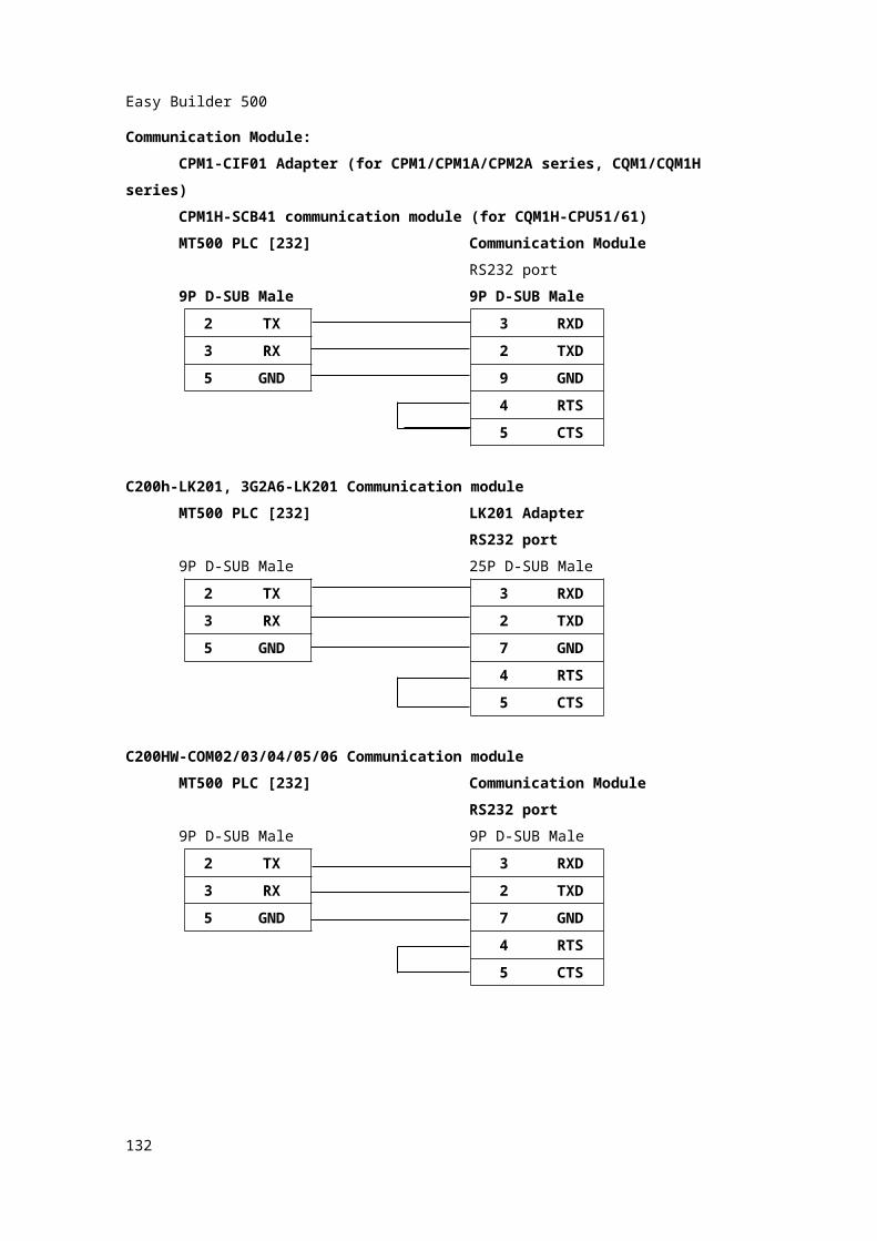
Communication Module:CPM1-CIF01 Adapter (for CPM1/CPM1A/CPM2A series, CQM1/CQM1H
series)CPM1H-SCB41 communication module (for CQM1H-CPU51/61)MT500 PLC [232] Communication Module
RS232 port9P D-SUB Male 9P D-SUB Male
2 TX 3 RXD3 RX 2 TXD
5 GND 9 GND
4 RTS5 CTS
C200h-LK201, 3G2A6-LK201 Communication moduleMT500 PLC [232] LK201 Adapter
RS232 port9P D-SUB Male 25P D-SUB Male
2 TX 3 RXD3 RX 2 TXD
5 GND 7 GND
4 RTS5 CTS
C200HW-COM02/03/04/05/06 Communication moduleMT500 PLC [232] Communication Module
RS232 port9P D-SUB Male 9P D-SUB Male
2 TX 3 RXD3 RX 2 TXD
5 GND 7 GND
4 RTS
130

Easy Builder 500
5 CTS
131
Easy Builder 500
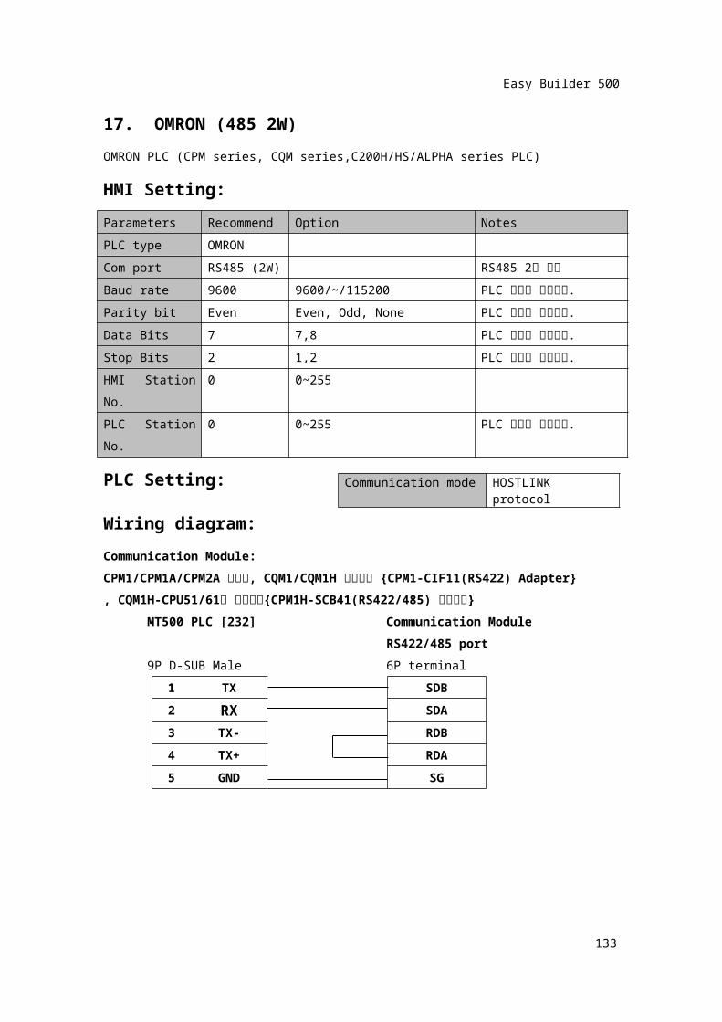
17. OMRON (485 2W)OMRON PLC (CPM series, CQM series,C200H/HS/ALPHA series PLC)HMI Setting:Parameters
Recommend
Option Notes
PLC type OMRONCom port RS485 (2W) RS485 2선 모드
Baud rate 9600 9600/~/115200 PLC 셋팅과 일치시킴.Parity bit Even Even, Odd, None PLC 셋팅과 일치시킴.Data Bits 7 7,8 PLC 셋팅과 일치시킴.Stop Bits 2 1,2 PLC 셋팅과 일치시킴.HMI Station No.
0 0~255
PLC Station No.
0 0~255 PLC 셋팅과 일치시킴.
PLC Setting: Wiring diagram:Communication Module:CPM1/CPM1A/CPM2A 시리즈, CQM1/CQM1H 시리즈용 {CPM1-CIF11(RS422) Adapter}, CQM1H-CPU51/61용 통신카드{CPM1H-SCB41(RS422/485) 통신카드}
MT500 PLC [232] Communication ModuleRS422/485 port
9P D-SUB Male 6P terminal1 TX SDB2 RX SDA3 TX- RDB 4 TX+ RDA5 GND SG
132
Communication mode HOSTLINK protocol
Easy Builder 500
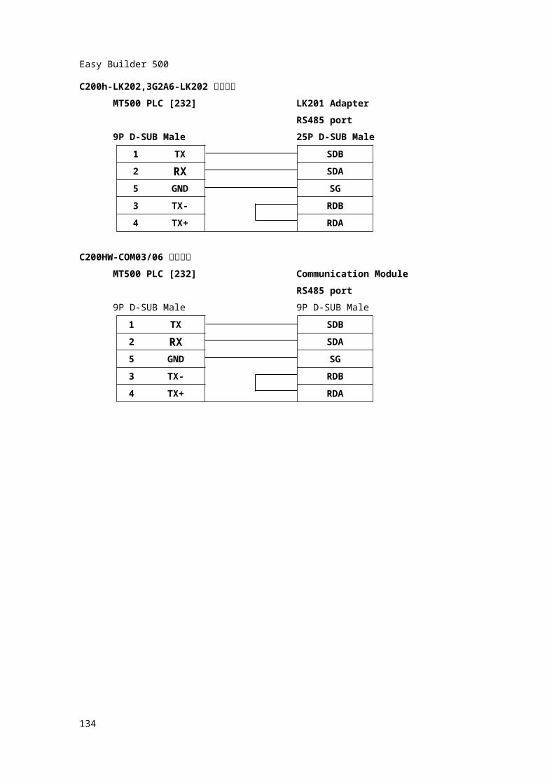
C200h-LK202,3G2A6-LK202 통신카드
MT500 PLC [232] LK201 AdapterRS485 port
9P D-SUB Male 25P D-SUB Male1 TX SDB2 RX SDA5 GND SG3 TX- RDB4 TX+ RDA
C200HW-COM03/06 통신카드
MT500 PLC [232] Communication ModuleRS485 port
9P D-SUB Male 9P D-SUB Male1 TX SDB2 RX SDA5 GND SG3 TX- RDB4 TX+ RDA
133
Easy Builder 500
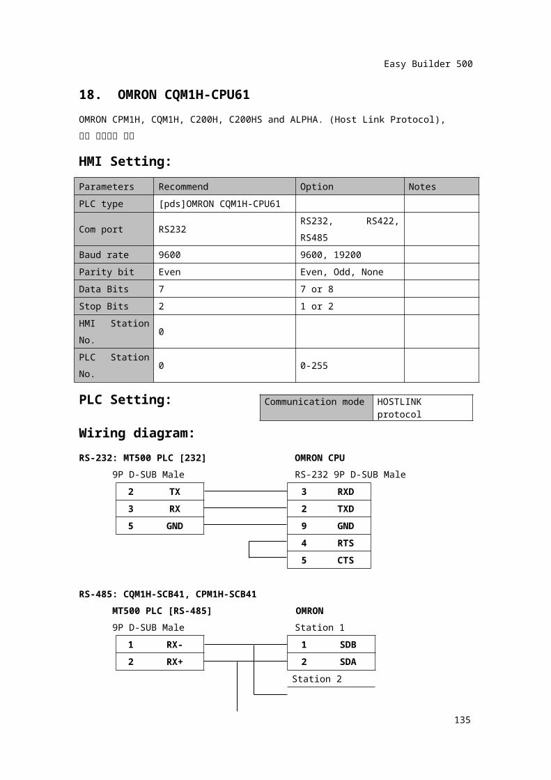
18. OMRON CQM1H-CPU61OMRON CPM1H, CQM1H, C200H, C200HS and ALPHA. (Host Link Protocol),확장 어드레스 모드
HMI Setting:Parameters Recommend Option NotesPLC type [pds]OMRON CQM1H-CPU61
Com port RS232RS232, RS422, RS485
Baud rate 9600 9600, 19200Parity bit Even Even, Odd, NoneData Bits 7 7 or 8Stop Bits 2 1 or 2HMI Station No.
0
PLC Station No.
0 0-255
PLC Setting:Wiring diagram:RS-232: MT500 PLC [232] OMRON CPU
9P D-SUB Male RS-232 9P D-SUB Male2 TX 3 RXD3 RX 2 TXD5 GND 9 GND
4 RTS5 CTS
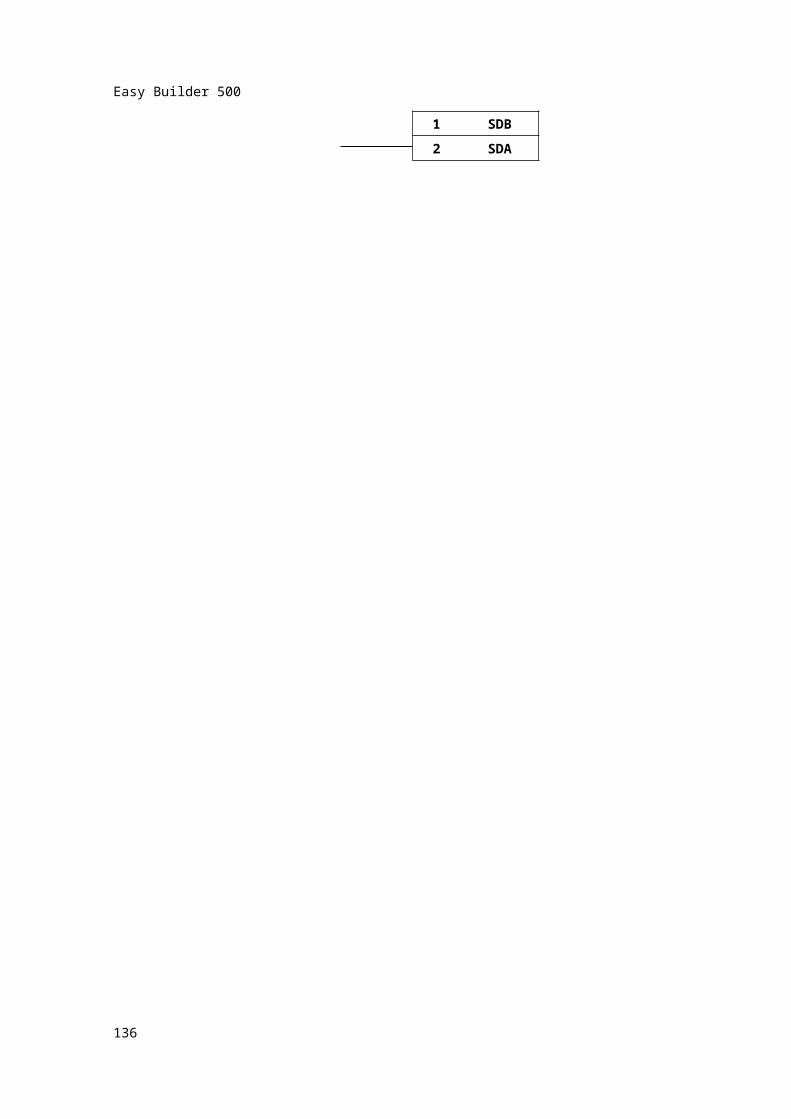
RS-485: CQM1H-SCB41, CPM1H-SCB41MT500 PLC [RS-485] OMRON9P D-SUB Male Station 1
1 RX- 1 SDB
2 RX+ 2 SDA
Station 2
134
Communication mode HOSTLINK protocol
Easy Builder 500
1 SDB2 SDA
135
Easy Builder 500
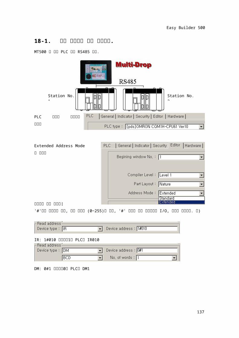
18-1. 확장 어드레스 모드 사용하기.MT500 과 다국 PLC 간의 RS485 통신.
PLC 타입과 통신상태
설정함
Extended Address Mode로 선택함
어드레스 형식 설정은:'#'앞에 스테이션 입력, 번호 형식은 (0~255)중 선택, '#' 뒤에는 설정 스테이션의 I/O, 데이터
레지스터. 예)
IR: 1#010 스테이션1번 PLC의 IR010
DM: 0#1 스테이션0번 PLC의 DM1
136
Station No. 1 Station No. 2
Easy Builder 500
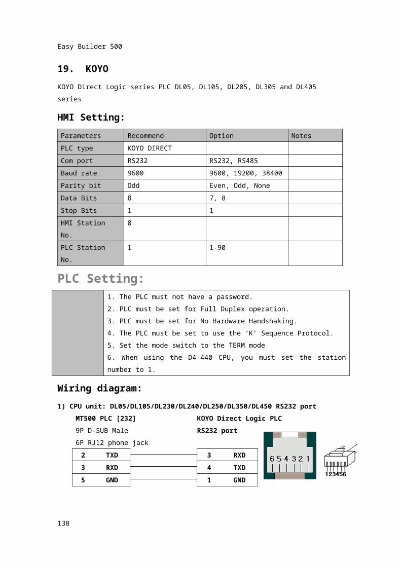
19. KOYOKOYO Direct Logic series PLC DL05, DL105, DL205, DL305 and DL405 seriesHMI Setting:Parameters Recommend Option NotesPLC type KOYO DIRECTCom port RS232 RS232, RS485Baud rate 9600 9600, 19200, 38400Parity bit Odd Even, Odd, NoneData Bits 8 7, 8Stop Bits 1 1HMI Station No. 0PLC Station No. 1 1-90
PLC Setting:1. The PLC must not have a password.
2. PLC must be set for Full Duplex operation.
3. PLC must be set for No Hardware Handshaking.
4. The PLC must be set to use the ‘K’ Sequence Protocol.
5. Set the mode switch to the TERM mode
6. When using the D4-440 CPU, you must set the station number to 1.
Wiring diagram:1) CPU unit: DL05/DL105/DL230/DL240/DL250/DL350/DL450 RS232 port
MT500 PLC [232] KOYO Direct Logic PLC9P D-SUB Male RS232 port6P RJ12 phone jack
2 TXD 3 RXD3 RXD 4 TXD5 GND 1 GND
137
Easy Builder 500
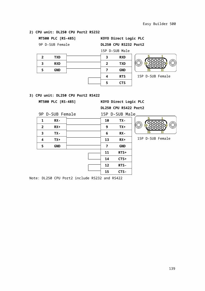
2) CPU unit: DL250 CPU Port2 RS232MT500 PLC [RS-485] KOYO Direct Logic PLC9P D-SUB Female DL250 CPU RS232 Port2
15P D-SUB Male2 TXD 3 RXD
3 RXD 2 TXD
5 GND 7 GND
4 RTS5 CTS
3) CPU unit: DL250 CPU Port2 RS422MT500 PLC [RS-485] KOYO Direct Logic PLC
DL250 CPU RS422 Port29P D-SUB Female 15P D-SUB Male
1 RX- 10 TX-2 RX+ 9 TX+3 TX- 6 RX-
4 TX+ 13 RX+5 GND 7 GND
11 RTS+14 CTS+12 RTS-15 CTS-
Note: DL250 CPU Port2 include RS232 and RS422
138
15P D-SUB Female
15P D-SUB Female
Easy Builder 500
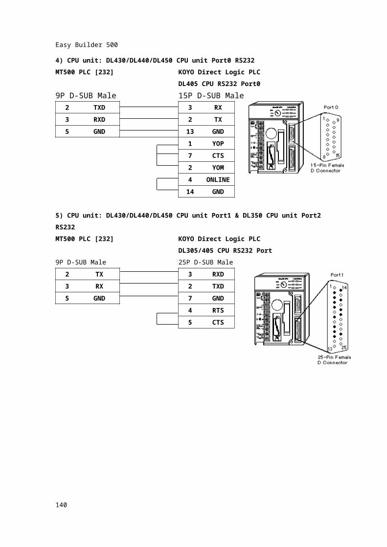
4) CPU unit: DL430/DL440/DL450 CPU unit Port0 RS232MT500 PLC [232] KOYO Direct Logic PLC
DL405 CPU RS232 Port09P D-SUB Male 15P D-SUB Male
2 TXD 3 RX
3 RXD 2 TX5 GND 13 GND
1 YOP7 CTS2 YOM4 ONLIN
E14 GND
5) CPU unit: DL430/DL440/DL450 CPU unit Port1 & DL350 CPU unit Port2 RS232MT500 PLC [232] KOYO Direct Logic PLC
DL305/405 CPU RS232 Port9P D-SUB Male 25P D-SUB Male
2 TX 3 RXD
3 RX 2 TXD5 GND 7 GND
4 RTS5 CTS
139
Easy Builder 500
140
Easy Builder 500
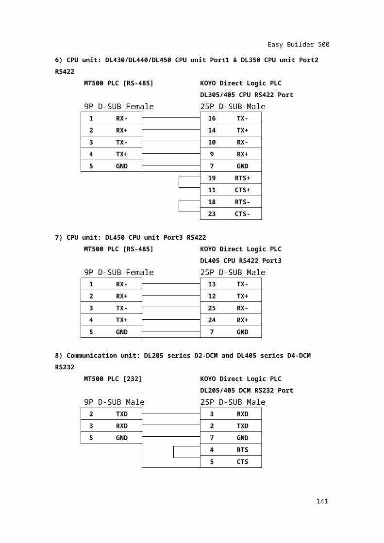
6) CPU unit: DL430/DL440/DL450 CPU unit Port1 & DL350 CPU unit Port2 RS422
MT500 PLC [RS-485] KOYO Direct Logic PLCDL305/405 CPU RS422 Port
9P D-SUB Female 25P D-SUB Male1 RX- 16 TX-2 RX+ 14 TX+3 TX- 10 RX-4 TX+ 9 RX+5 GND 7 GND
19 RTS+11 CTS+18 RTS-23 CTS-
7) CPU unit: DL450 CPU unit Port3 RS422MT500 PLC [RS-485] KOYO Direct Logic PLC
DL405 CPU RS422 Port39P D-SUB Female 25P D-SUB Male
1 RX- 13 TX-2 RX+ 12 TX+3 TX- 25 RX-4 TX+ 24 RX+5 GND 7 GND
8) Communication unit: DL205 series D2-DCM and DL405 series D4-DCM RS232
MT500 PLC [232] KOYO Direct Logic PLCDL205/405 DCM RS232 Port
9P D-SUB Male 25P D-SUB Male2 TXD 3 RXD3 RXD 2 TXD
141
Easy Builder 500
5 GND 7 GND4 RTS5 CTS
142
Easy Builder 500
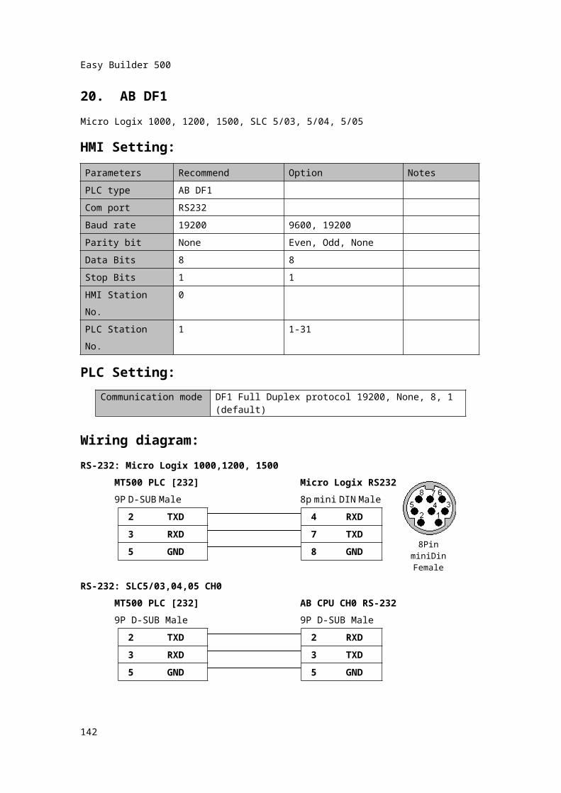
20. AB DF1Micro Logix 1000, 1200, 1500, SLC 5/03, 5/04, 5/05HMI Setting:Parameters Recommend Option NotesPLC type AB DF1Com port RS232Baud rate 19200 9600, 19200Parity bit None Even, Odd, NoneData Bits 8 8Stop Bits 1 1HMI Station No. 0PLC Station No. 1 1-31
PLC Setting:
Wiring diagram:RS-232: Micro Logix 1000,1200, 1500
MT500 PLC [232] Micro Logix RS2329P D-SUB Male 8p mini DIN Male
2 TXD 4 RXD3 RXD 7 TXD
5 GND 8 GND
RS-232: SLC5/03,04,05 CH0MT500 PLC [232] AB CPU CH0 RS-2329P D-SUB Male 9P D-SUB Male
2 TXD 2 RXD3 RXD 3 TXD5 GND 5 GND
143
Communication mode DF1 Full Duplex protocol 19200, None, 8, 1 (default)
8Pin miniDinFemale
Easy Builder 500
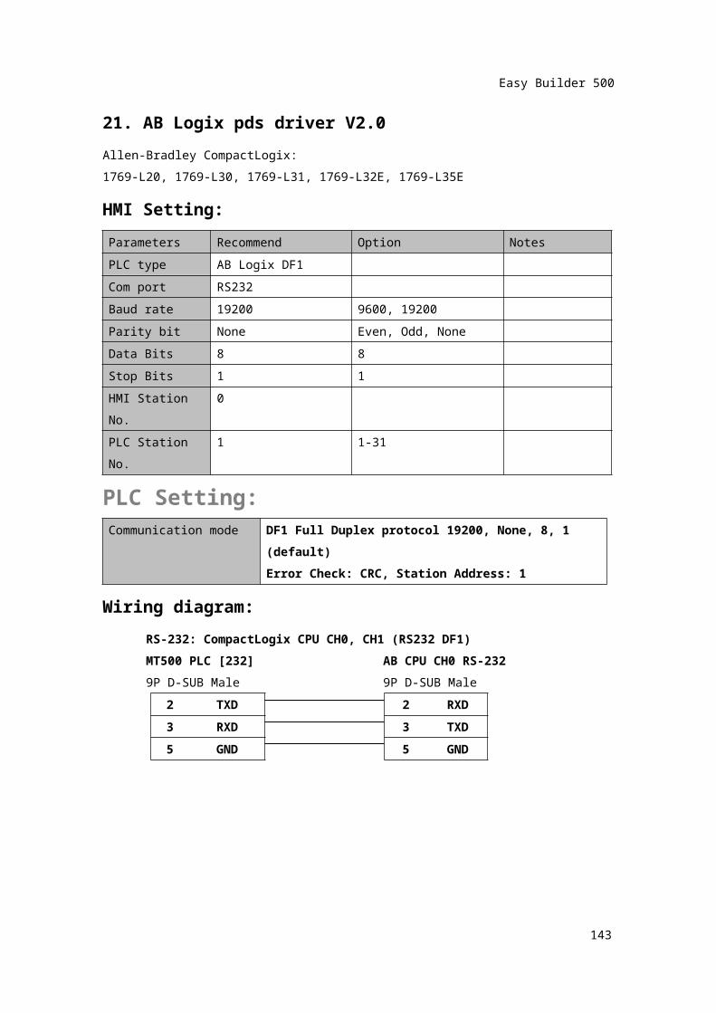
21. AB Logix pds driver V2.0Allen-Bradley CompactLogix:1769-L20, 1769-L30, 1769-L31, 1769-L32E, 1769-L35EHMI Setting:Parameters Recommend Option NotesPLC type AB Logix DF1Com port RS232Baud rate 19200 9600, 19200Parity bit None Even, Odd, NoneData Bits 8 8Stop Bits 1 1HMI Station No. 0PLC Station No. 1 1-31
PLC Setting:Communication mode DF1 Full Duplex protocol 19200, None, 8, 1
(default)Error Check: CRC, Station Address: 1
Wiring diagram:RS-232: CompactLogix CPU CH0, CH1 (RS232 DF1)MT500 PLC [232] AB CPU CH0 RS-2329P D-SUB Male 9P D-SUB Male
2 TXD 2 RXD3 RXD 3 TXD5 GND 5 GND
144
Easy Builder 500
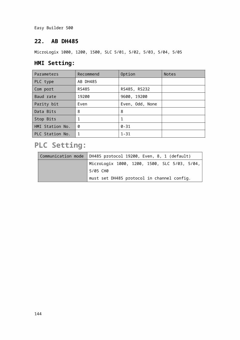
22. AB DH485MicroLogix 1000, 1200, 1500, SLC 5/01, 5/02, 5/03, 5/04, 5/05HMI Setting:Parameters Recommend Option NotesPLC type AB DH485Com port RS485 RS485, RS232Baud rate 19200 9600, 19200Parity bit Even Even, Odd, NoneData Bits 8 8Stop Bits 1 1HMI Station No. 0 0-31PLC Station No. 1 1-31
PLC Setting:Communication mode DH485 protocol 19200, Even, 8, 1 (default)
MicroLogix 1000, 1200, 1500, SLC 5/03, 5/04, 5/05 CH0must set DH485 protocol in channel config.
145
Easy Builder 500
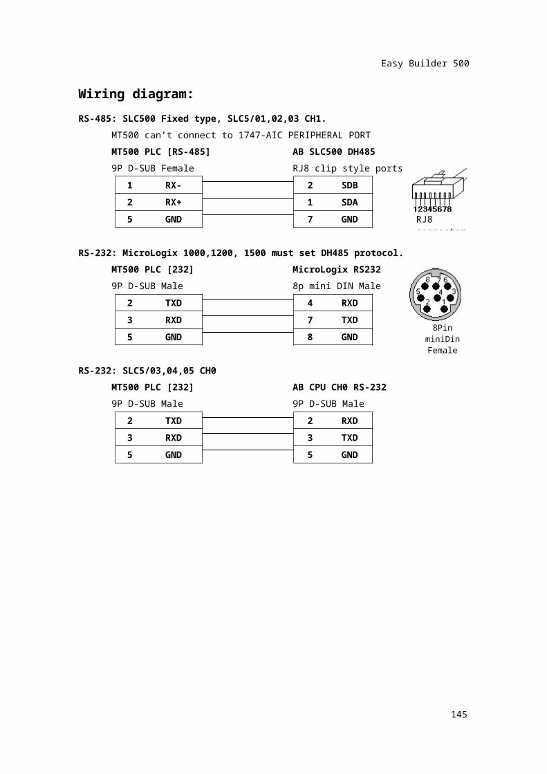
Wiring diagram:RS-485: SLC500 Fixed type, SLC5/01,02,03 CH1.
MT500 can’t connect to 1747-AIC PERIPHERAL PORTMT500 PLC [RS-485] AB SLC500 DH4859P D-SUB Female RJ8 clip style ports
1 RX- 2 SDB2 RX+ 1 SDA
5 GND 7 GND
RS-232: MicroLogix 1000,1200, 1500 must set DH485 protocol.MT500 PLC [232] MicroLogix RS2329P D-SUB Male 8p mini DIN Male
2 TXD 4 RXD3 RXD 7 TXD
5 GND 8 GND
RS-232: SLC5/03,04,05 CH0MT500 PLC [232] AB CPU CH0 RS-2329P D-SUB Male 9P D-SUB Male
2 TXD 2 RXD3 RXD 3 TXD5 GND 5 GND
146
8Pin miniDinFemale
RJ8 connector
Easy Builder 500
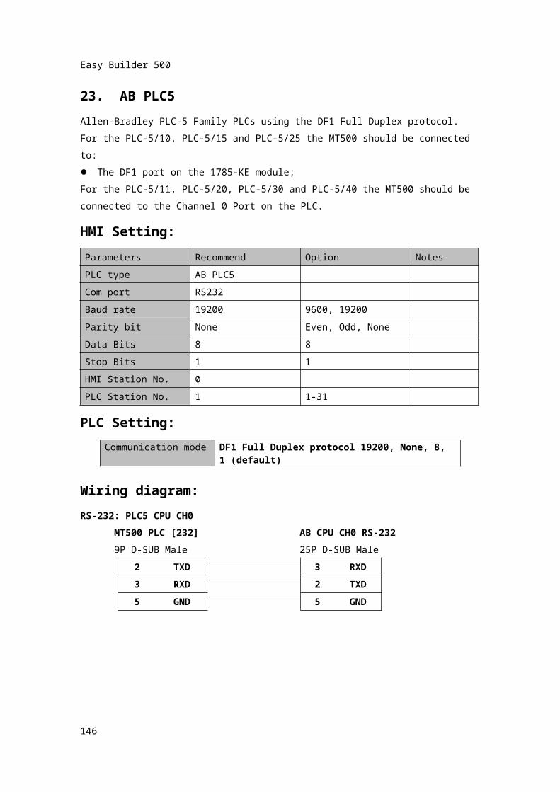
23. AB PLC5Allen-Bradley PLC-5 Family PLCs using the DF1 Full Duplex protocol.For the PLC-5/10, PLC-5/15 and PLC-5/25 the MT500 should be connected to: The DF1 port on the 1785-KE module;For the PLC-5/11, PLC-5/20, PLC-5/30 and PLC-5/40 the MT500 should be connected to the Channel 0 Port on the PLC.HMI Setting:Parameters Recommend Option NotesPLC type AB PLC5Com port RS232Baud rate 19200 9600, 19200Parity bit None Even, Odd, NoneData Bits 8 8Stop Bits 1 1HMI Station No. 0PLC Station No. 1 1-31
PLC Setting:
Wiring diagram:RS-232: PLC5 CPU CH0
MT500 PLC [232] AB CPU CH0 RS-2329P D-SUB Male 25P D-SUB Male
2 TXD 3 RXD3 RXD 2 TXD5 GND 5 GND
147
Communication mode DF1 Full Duplex protocol 19200, None, 8, 1 (default)
Easy Builder 500
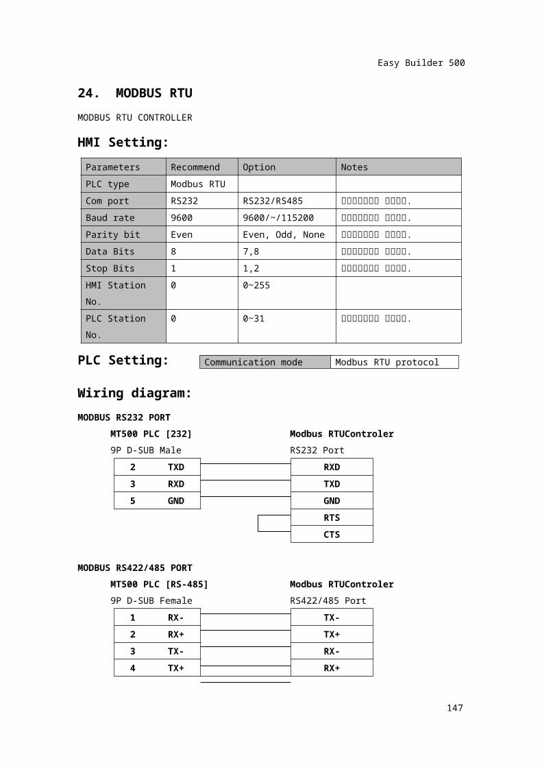
24. MODBUS RTUMODBUS RTU CONTROLLERHMI Setting:
Parameters Recommend Option NotesPLC type Modbus RTUCom port RS232 RS232/RS485 콘트롤러셋팅과 일치시킴.Baud rate 9600 9600/~/115200 콘트롤러셋팅과 일치시킴.Parity bit Even Even, Odd, None 콘트롤러셋팅과 일치시킴.Data Bits 8 7,8 콘트롤러셋팅과 일치시킴.Stop Bits 1 1,2 콘트롤러셋팅과 일치시킴.HMI Station No. 0 0~255PLC Station No. 0 0~31 콘트롤러셋팅과 일치시킴.
PLC Setting:Wiring diagram:MODBUS RS232 PORT
MT500 PLC [232] Modbus RTUControler9P D-SUB Male RS232 Port
2 TXD RXD3 RXD TXD5 GND GND
RTSCTS
MODBUS RS422/485 PORTMT500 PLC [RS-485] Modbus RTUControler9P D-SUB Female RS422/485 Port
1 RX- TX-2 RX+ TX+3 TX- RX-4 TX+ RX+5 GND GND
148
Communication mode Modbus RTU protocol
Easy Builder 500
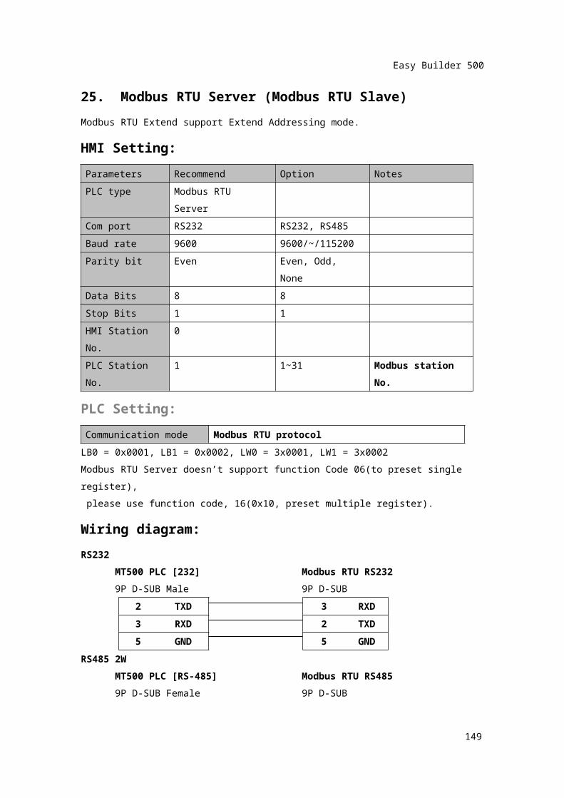
25. Modbus RTU Server (Modbus RTU Slave)Modbus RTU Extend support Extend Addressing mode.HMI Setting:Parameters Recommend Option NotesPLC type Modbus RTU ServerCom port RS232 RS232, RS485Baud rate 9600 9600/~/115200Parity bit Even Even, Odd, NoneData Bits 8 8Stop Bits 1 1HMI Station No. 0PLC Station No. 1 1~31 Modbus station
No.
PLC Setting:Communication mode Modbus RTU protocol
LB0 = 0x0001, LB1 = 0x0002, LW0 = 3x0001, LW1 = 3x0002 Modbus RTU Server doesn’t support function Code 06(to preset single register), please use function code, 16(0x10, preset multiple register).Wiring diagram:RS232
MT500 PLC [232] Modbus RTU RS2329P D-SUB Male 9P D-SUB
2 TXD 3 RXD3 RXD 2 TXD5 GND 5 GND
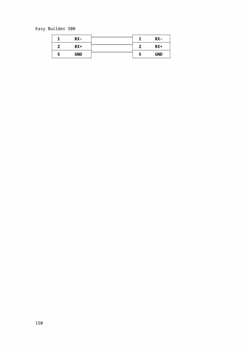
RS485 2WMT500 PLC [RS-485] Modbus RTU RS4859P D-SUB Female 9P D-SUB
1 RX- 1 RX-2 RX+ 2 RX+5 GND 5 GND
149
Easy Builder 500
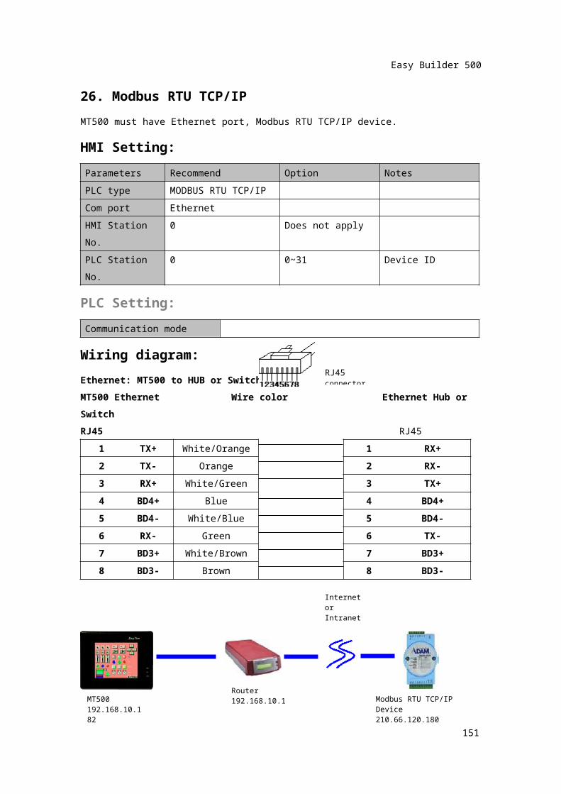
26. Modbus RTU TCP/IPMT500 must have Ethernet port, Modbus RTU TCP/IP device.HMI Setting:Parameters Recommend Option NotesPLC type MODBUS RTU TCP/IPCom port EthernetHMI Station No. 0 Does not applyPLC Station No. 0 0~31 Device ID
PLC Setting:Communication mode
Wiring diagram:Ethernet: MT500 to HUB or SwitchMT500 Ethernet Wire color Ethernet Hub or SwitchRJ45 RJ45
1 TX+ White/Orange 1 RX+2 TX- Orange 2 RX-3 RX+ White/Green 3 TX+4 BD4+ Blue 4 BD4+5 BD4- White/Blue 5 BD4-6 RX- Green 6 TX-7 BD3+ White/Brown 7 BD3+8 BD3- Brown 8 BD3-
150
RJ45 connector
MT500192.168.10.182
Internet orIntranet
Modbus RTU TCP/IP Device210.66.120.180
Router192.168.10.1
Easy Builder 500
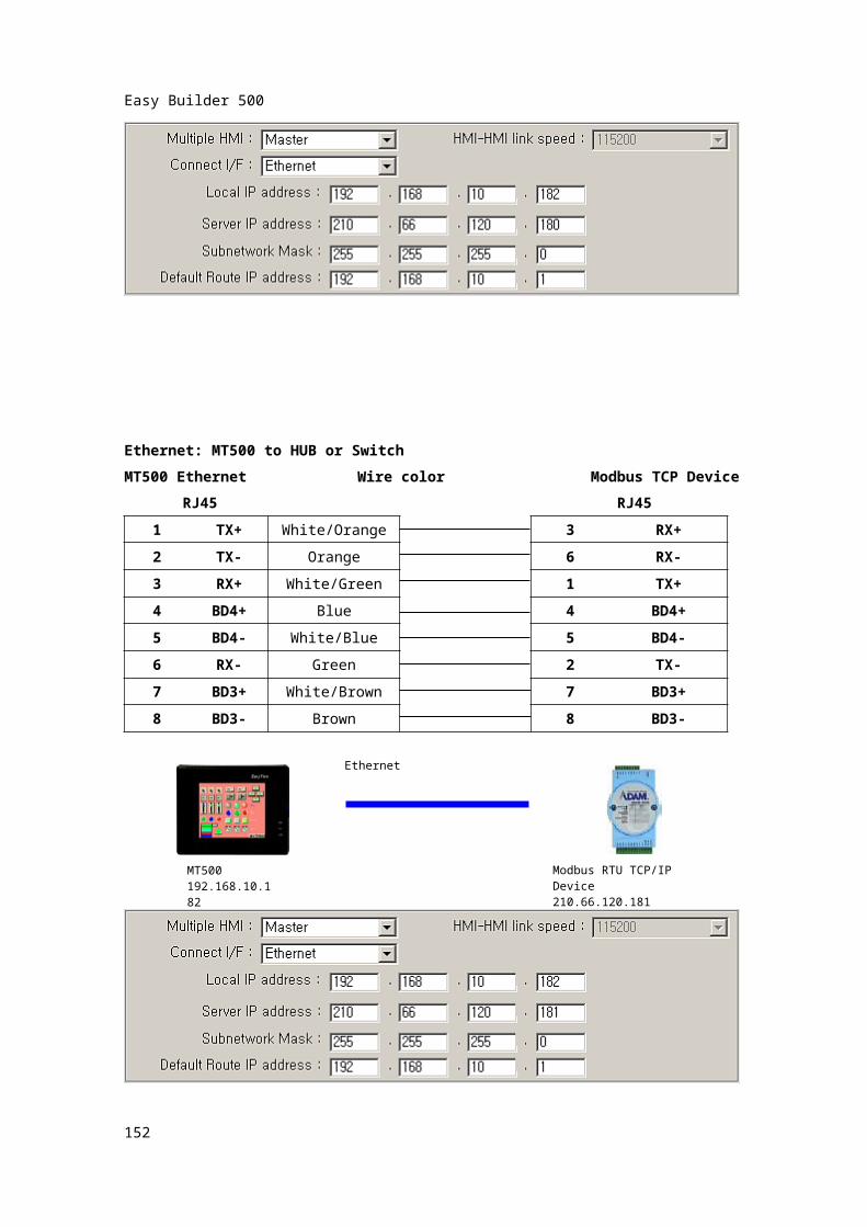
Ethernet: MT500 to HUB or SwitchMT500 Ethernet Wire color Modbus TCP Device
RJ45 RJ451 TX+ White/Orange 3 RX+2 TX- Orange 6 RX-3 RX+ White/Green 1 TX+4 BD4+ Blue 4 BD4+5 BD4- White/Blue 5 BD4-6 RX- Green 2 TX-7 BD3+ White/Brown 7 BD3+8 BD3- Brown 8 BD3-
151
MT500192.168.10.182
Ethernet
Modbus RTU TCP/IP Device210.66.120.181
Easy Builder 500
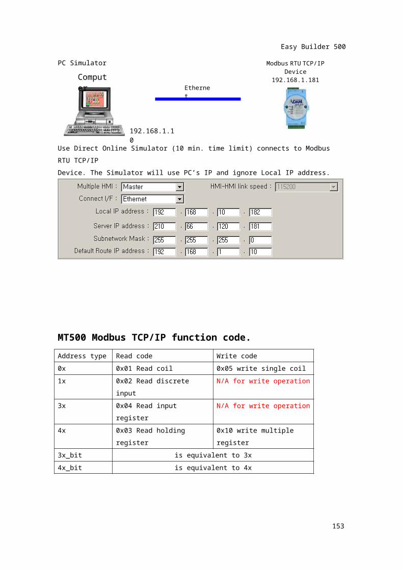
PC Simulator
Use Direct Online Simulator (10 min. time limit) connects to Modbus RTU TCP/IPDevice. The Simulator will use PC’s IP and ignore Local IP address.
MT500 Modbus TCP/IP function code.Address type Read code Write code0x 0x01 Read coil 0x05 write single coil1x 0x02 Read discrete input N/A for write operation3x 0x04 Read input register N/A for write operation4x 0x03 Read holding register 0x10 write multiple
register3x_bit is equivalent to 3x4x_bit is equivalent to 4x
152
EthernetComputer
Modbus RTU TCP/IP Device192.168.1.181
192.168.1.10
Easy Builder 500
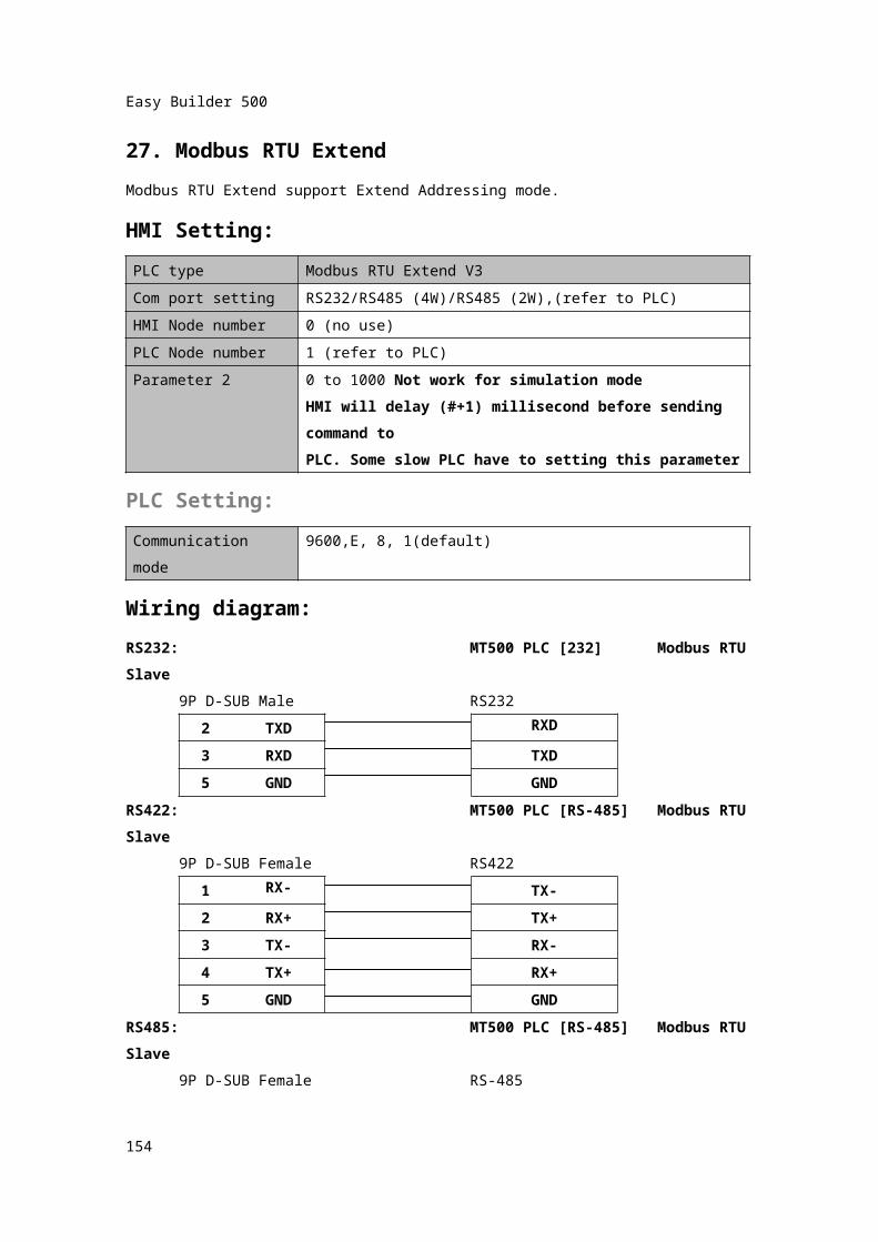
27. Modbus RTU ExtendModbus RTU Extend support Extend Addressing mode.HMI Setting:PLC type Modbus RTU Extend V3Com port setting RS232/RS485 (4W)/RS485 (2W),(refer to PLC)HMI Node number 0 (no use)PLC Node number 1 (refer to PLC)Parameter 2 0 to 1000 Not work for simulation mode
HMI will delay (#+1) millisecond before sending command toPLC. Some slow PLC have to setting this parameter
PLC Setting:Communication mode
9600,E, 8, 1(default)
Wiring diagram:RS232: MT500 PLC [232] Modbus RTU Slave
9P D-SUB Male RS2322 TXD RXD
3 RXD TXD5 GND GND
RS422: MT500 PLC [RS-485] Modbus RTU Slave
9P D-SUB Female RS4221 RX- TX-2 RX+ TX+3 TX- RX-4 TX+ RX+5 GND GND
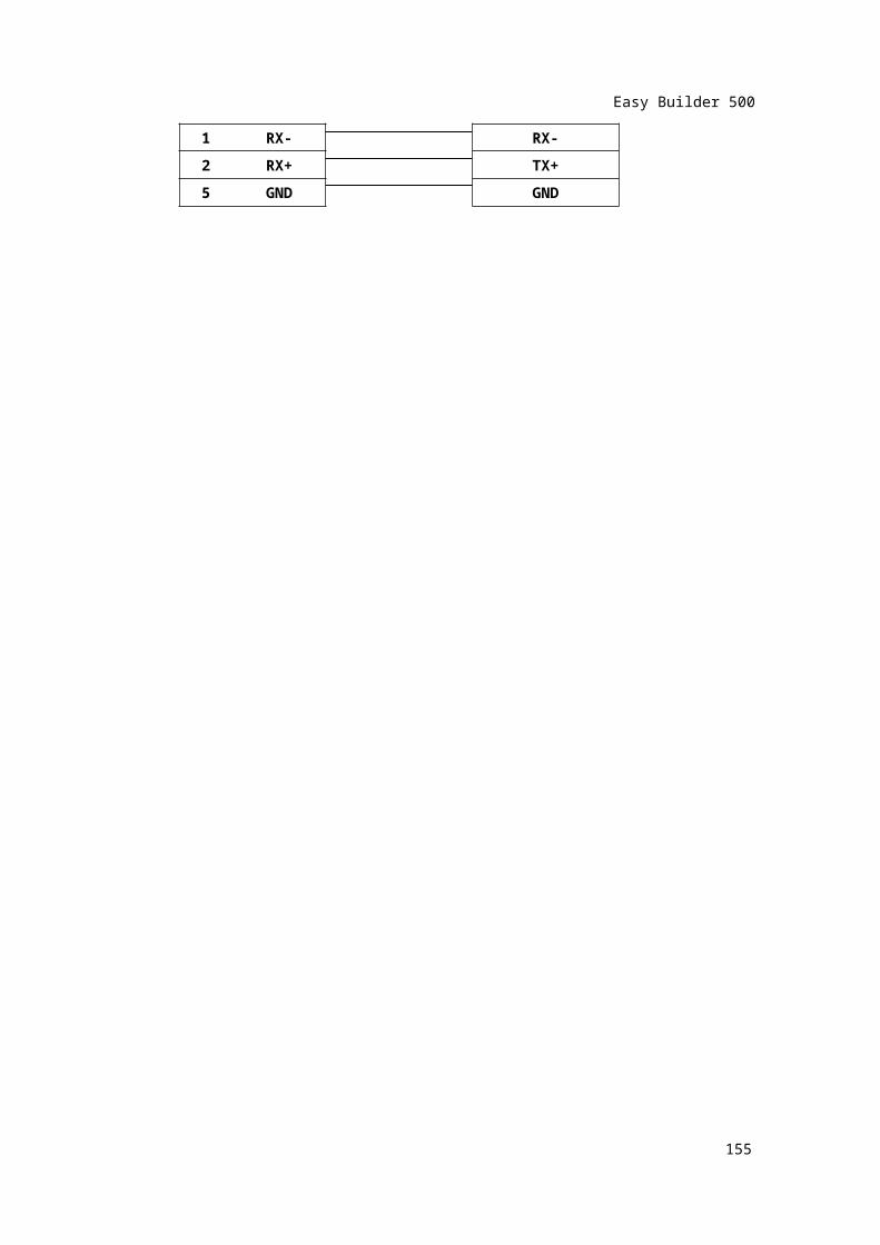
RS485: MT500 PLC [RS-485] Modbus RTU Slave
9P D-SUB Female RS-4851 RX- RX-2 RX+ TX+5 GND GND
153
Easy Builder 500
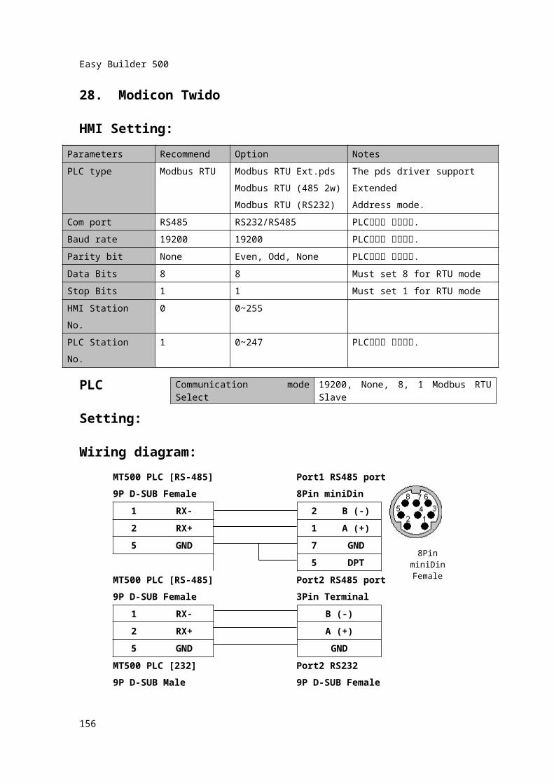
28. Modicon TwidoHMI Setting:
Parameters Recommend Option NotesPLC type Modbus RTU Modbus RTU Ext.pds
Modbus RTU (485 2w)Modbus RTU (RS232)
The pds driver support ExtendedAddress mode.
Com port RS485 RS232/RS485 PLC설정과 일치시킴.Baud rate 19200 19200 PLC설정과 일치시킴.Parity bit None Even, Odd, None PLC설정과 일치시킴.Data Bits 8 8 Must set 8 for RTU modeStop Bits 1 1 Must set 1 for RTU modeHMI Station No. 0 0~255PLC Station No. 1 0~247 PLC설정과 일치시킴.
PLC Setting:Wiring diagram:
MT500 PLC [RS-485] Port1 RS485 port9P D-SUB Female 8Pin miniDin
1 RX- 2 B (-)2 RX+ 1 A (+)
5 GND 7
GND
5 DPTMT500 PLC [RS-485] Port2 RS485 port9P D-SUB Female 3Pin Terminal
1 RX- B (-)2 RX+ A (+)5 GND GND
MT500 PLC [232] Port2 RS2329P D-SUB Male 9P D-SUB Female
2 TXD 2 RXD3 RXD 3 TXD5 GND 5 GND
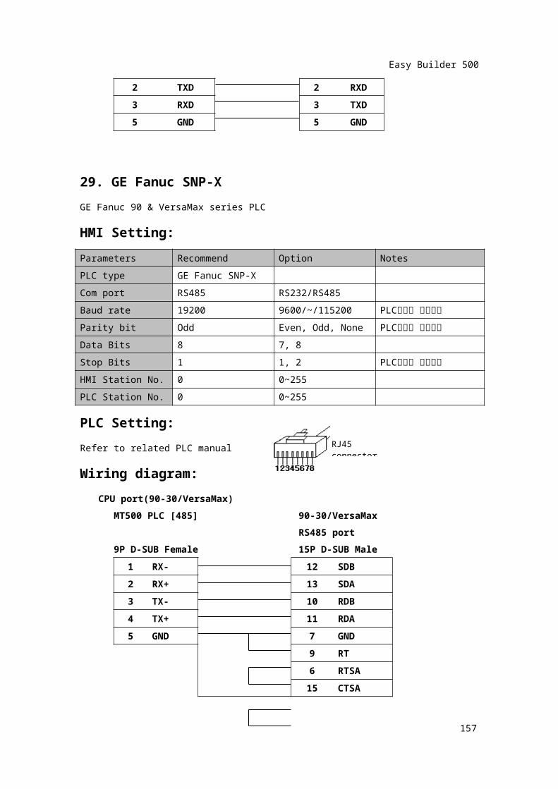
29. GE Fanuc SNP-X
154
Communication mode Select
19200, None, 8, 1 Modbus RTU Slave
8Pin miniDinFemale
Easy Builder 500
GE Fanuc 90 & VersaMax series PLCHMI Setting:Parameters Recommend Option NotesPLC type GE Fanuc SNP-XCom port RS485 RS232/RS485Baud rate 19200 9600/~/115200 PLC설정과 일치시킴
Parity bit Odd Even, Odd, None PLC설정과 일치시킴
Data Bits 8 7, 8Stop Bits 1 1, 2 PLC설정과 일치시킴
HMI Station No. 0 0~255PLC Station No. 0 0~255PLC Setting:Refer to related PLC manualWiring diagram:
CPU port(90-30/VersaMax)MT500 PLC [485] 90-30/VersaMax
RS485 port9P D-SUB Female 15P D-SUB Male
1 RX- 12 SDB2 RX+ 13 SDA3 TX- 10 RDB4 TX+ 11 RDA5 GND 7 GND
9 RT6 RTSA
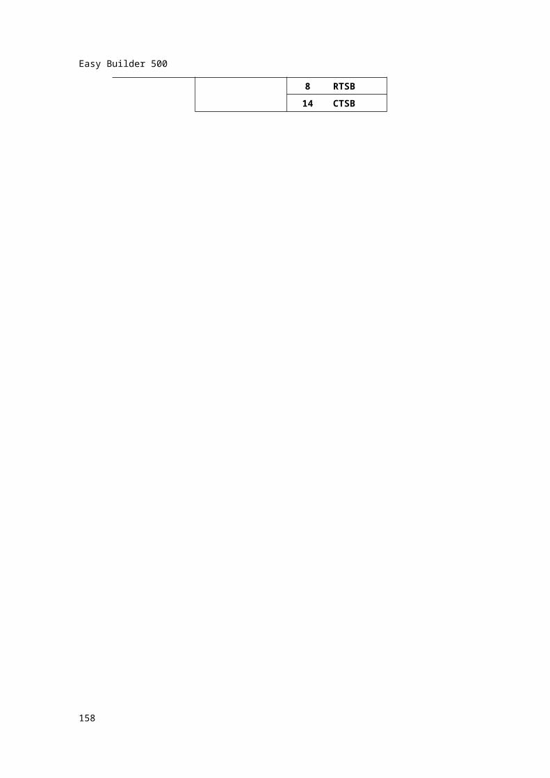
15 CTSA8 RTSB
14 CTSB
155
RJ45 connector
Easy Builder 500
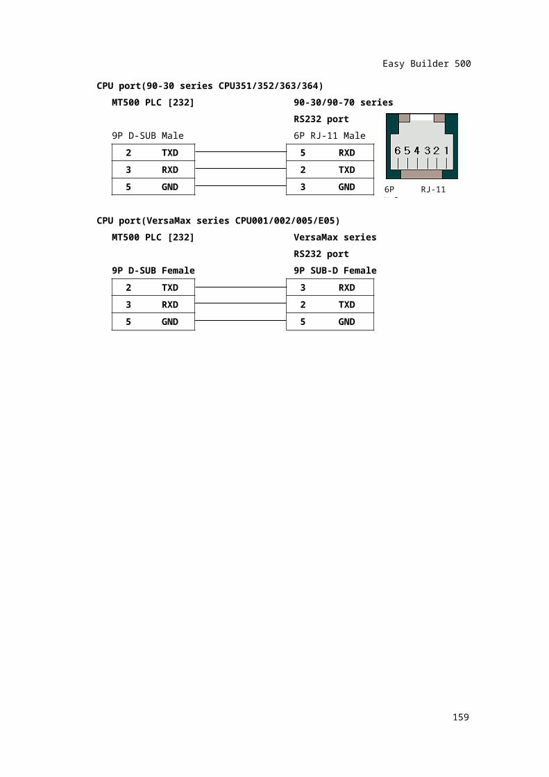
CPU port(90-30 series CPU351/352/363/364)MT500 PLC [232] 90-30/90-70 series
RS232 port9P D-SUB Male 6P RJ-11 Male
2 TXD 5 RXD3 RXD 2 TXD5 GND 3 GND
CPU port(VersaMax series CPU001/002/005/E05)MT500 PLC [232] VersaMax series
RS232 port9P D-SUB Female 9P SUB-D Female
2 TXD 3 RXD3 RXD 2 TXD5 GND 5 GND
156
6P RJ-11 Male
Easy Builder 500
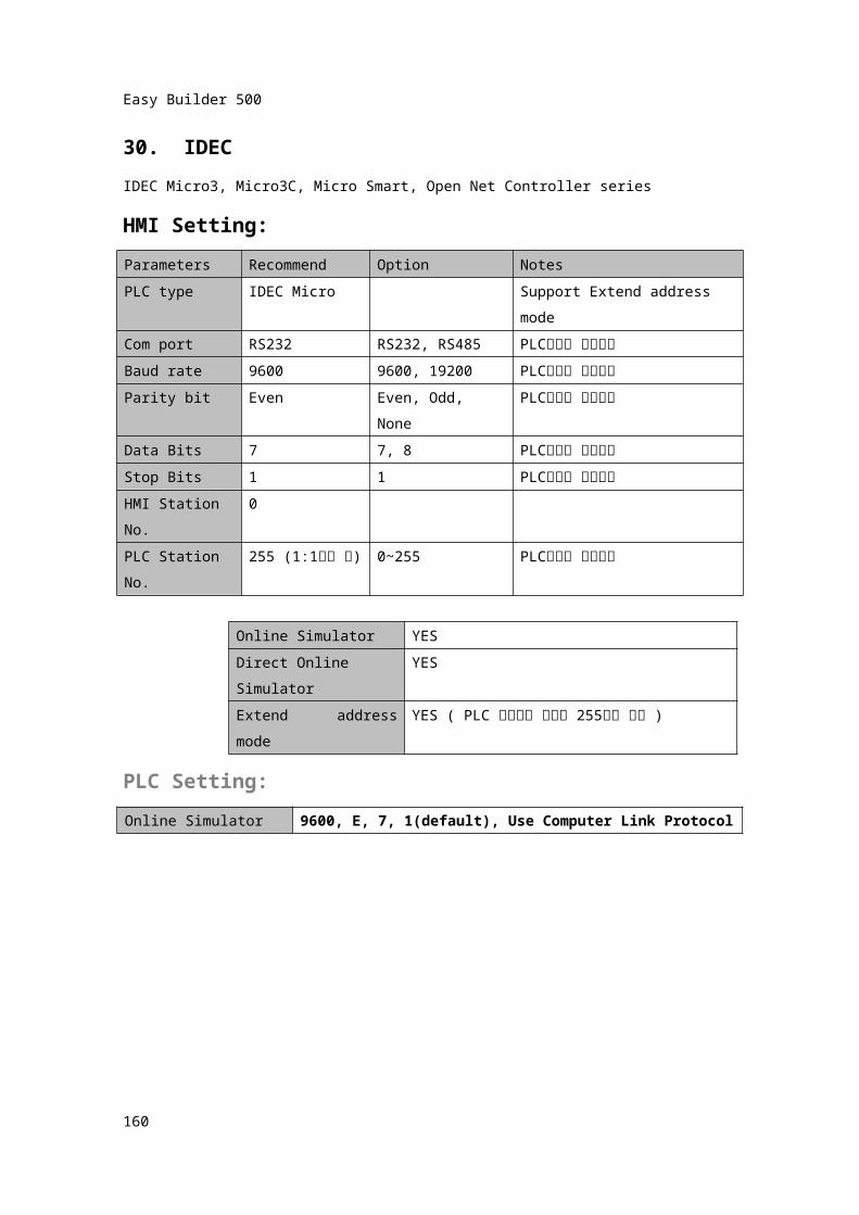
30. IDECIDEC Micro3, Micro3C, Micro Smart, Open Net Controller seriesHMI Setting:Parameters Recommend Option NotesPLC type IDEC Micro Support Extend address
modeCom port RS232 RS232, RS485 PLC설정과 일치시킴
Baud rate 9600 9600, 19200 PLC설정과 일치시킴
Parity bit Even Even, Odd, None PLC설정과 일치시킴
Data Bits 7 7, 8 PLC설정과 일치시킴
Stop Bits 1 1 PLC설정과 일치시킴
HMI Station No.
0
PLC Station No.
255 (1:1연결
시)0~255 PLC설정과 일치시킴
Online Simulator YESDirect Online Simulator
YES
Extend address mode YES ( PLC 스테이션 번호가 255이면 안됨 )PLC Setting:Online Simulator 9600, E, 7, 1(default), Use Computer Link Protocol
157
Easy Builder 500
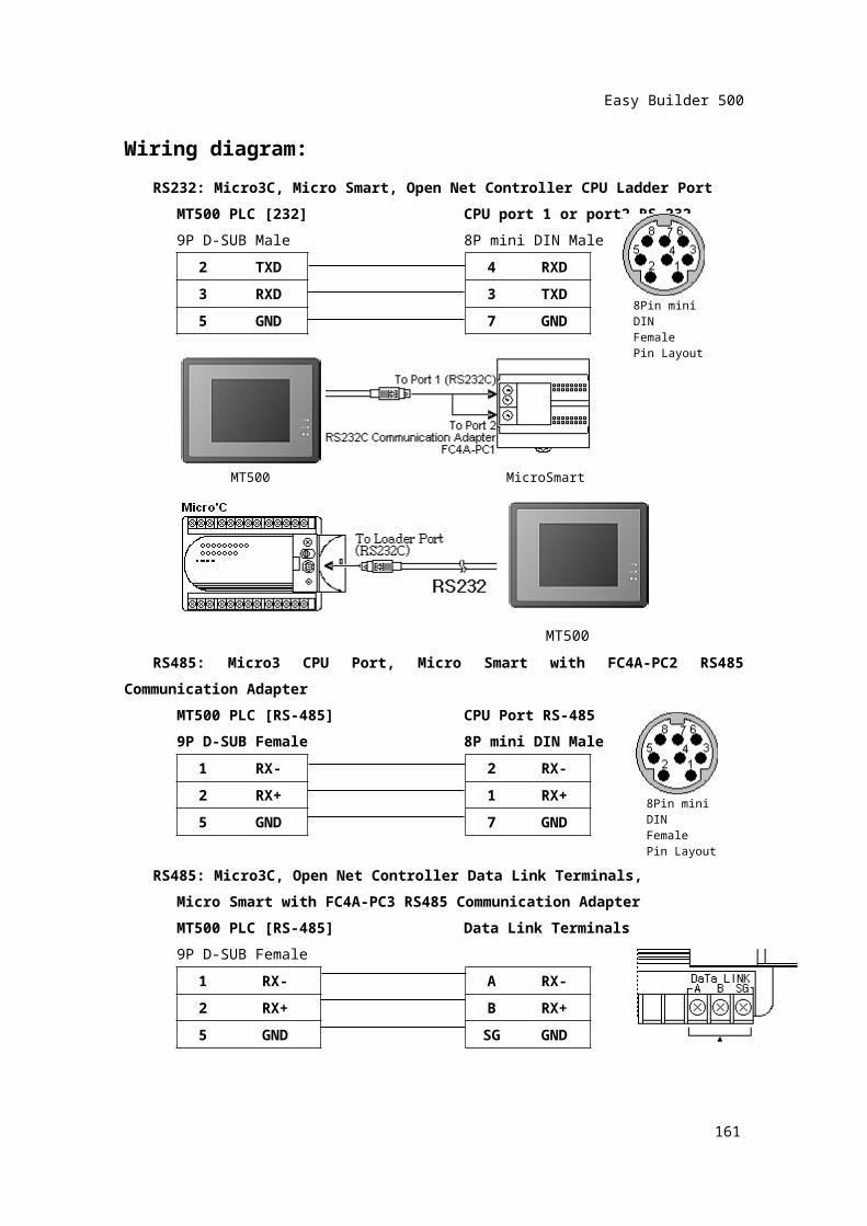
Wiring diagram:RS232: Micro3C, Micro Smart, Open Net Controller CPU Ladder Port
MT500 PLC [232] CPU port 1 or port2 RS-2329P D-SUB Male 8P mini DIN Male
2 TXD 4 RXD3 RXD 3 TXD
5 GND 7 GND
RS485: Micro3 CPU Port, Micro Smart with FC4A-PC2 RS485 Communication Adapter
MT500 PLC [RS-485] CPU Port RS-4859P D-SUB Female 8P mini DIN Male
1 RX- 2 RX-2 RX+ 1 RX+
5 GND 7 GND
RS485: Micro3C, Open Net Controller Data Link Terminals,Micro Smart with FC4A-PC3 RS485 Communication AdapterMT500 PLC [RS-485] Data Link Terminals9P D-SUB Female
1 RX- A RX-
158
8Pin mini DINFemale Pin Layout
MicroSmartMT500
MT500
8Pin mini DINFemale Pin Layout
Easy Builder 500
2 RX+ B RX+5 GND SG GND
159
Easy Builder 500
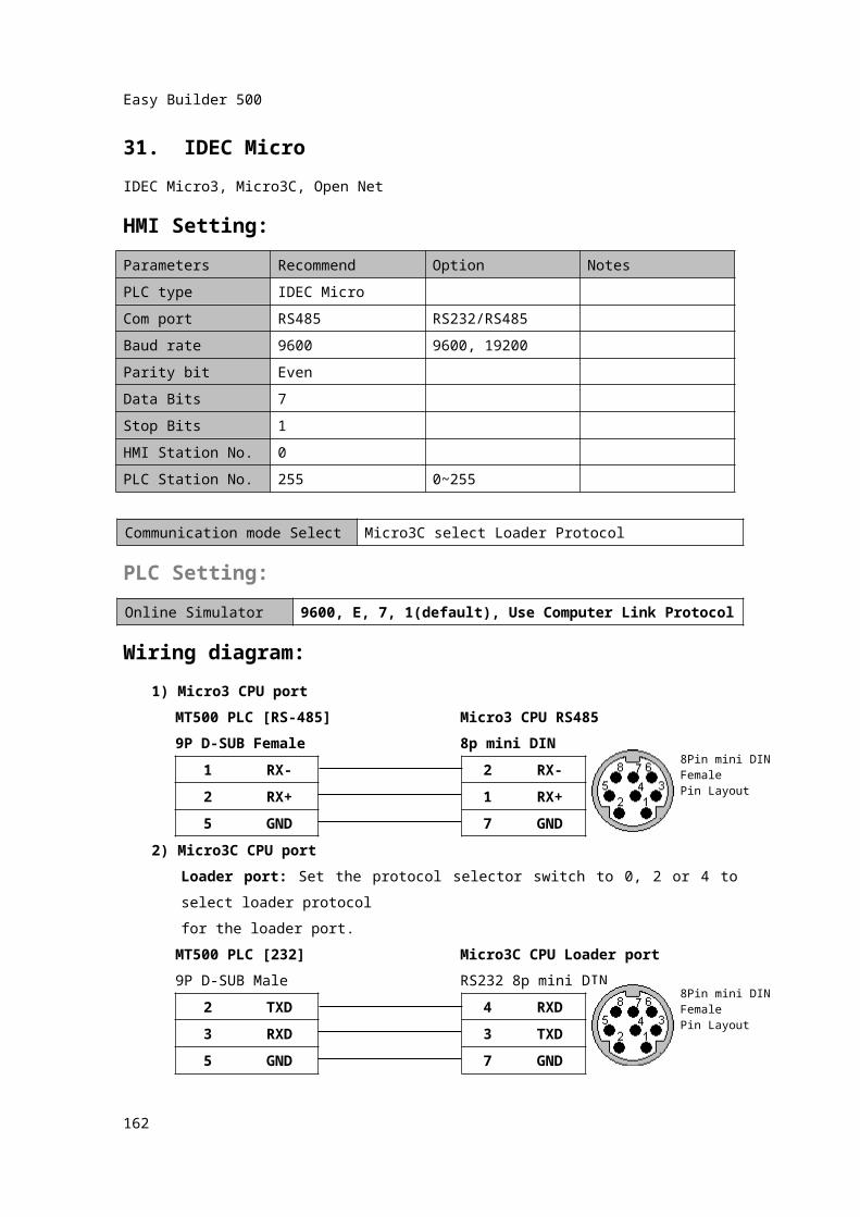
31. IDEC MicroIDEC Micro3, Micro3C, Open NetHMI Setting:Parameters Recommend Option NotesPLC type IDEC MicroCom port RS485 RS232/RS485Baud rate 9600 9600, 19200Parity bit EvenData Bits 7Stop Bits 1HMI Station No. 0PLC Station No. 255 0~255
Communication mode Select Micro3C select Loader ProtocolPLC Setting:Online Simulator 9600, E, 7, 1(default), Use Computer Link Protocol
Wiring diagram:1) Micro3 CPU port
MT500 PLC [RS-485] Micro3 CPU RS4859P D-SUB Female 8p mini DIN
1 RX- 2 RX-2 RX+ 1 RX+5 GND 7 GND
2) Micro3C CPU portLoader port: Set the protocol selector switch to 0, 2 or 4 to select loader protocol for the loader port.
MT500 PLC [232] Micro3C CPU Loader port9P D-SUB Male RS232 8p mini DIN
2 TXD 4 RXD3 RXD 3 TXD5 GND 7 GND
160
8Pin mini DINFemale Pin Layout
8Pin mini DINFemale Pin Layout
Easy Builder 500
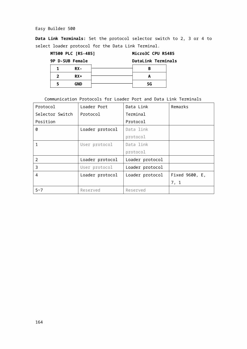
Data Link Terminals: Set the protocol selector switch to 2, 3 or 4 to select loader protocol for the Data Link Terminal.
MT500 PLC [RS-485] Micro3C CPU RS4859P D-SUB Female DataLink Terminals
1 RX- B2 RX+ A5 GND SG
Communication Protocols for Loader Port and Data Link TerminalsProtocol Selector Switch Position
Loader Port Protocol
Data Link TerminalProtocol
Remarks
0 Loader protocol Data link protocol1 User protocol Data link protocol2 Loader protocol Loader protocol3 User protocol Loader protocol4 Loader protocol Loader protocol Fixed 9600, E, 7, 15~7 Reserved Reserved
161
Easy Builder 500
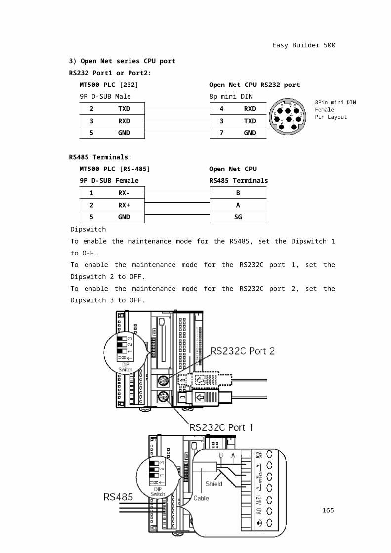
3) Open Net series CPU portRS232 Port1 or Port2:
MT500 PLC [232] Open Net CPU RS232 port9P D-SUB Male 8p mini DIN
2 TXD 4 RXD3 RXD 3 TXD5 GND 7 GND
RS485 Terminals:MT500 PLC [RS-485] Open Net CPU9P D-SUB Female RS485 Terminals
1 RX- B2 RX+ A5 GND SG
DipswitchTo enable the maintenance mode for the RS485, set the Dipswitch 1 to OFF.To enable the maintenance mode for the RS232C port 1, set the Dipswitch 2 to OFF.To enable the maintenance mode for the RS232C port 2, set the Dipswitch 3 to OFF.
162
8Pin mini DINFemale Pin Layout

Easy Builder 500
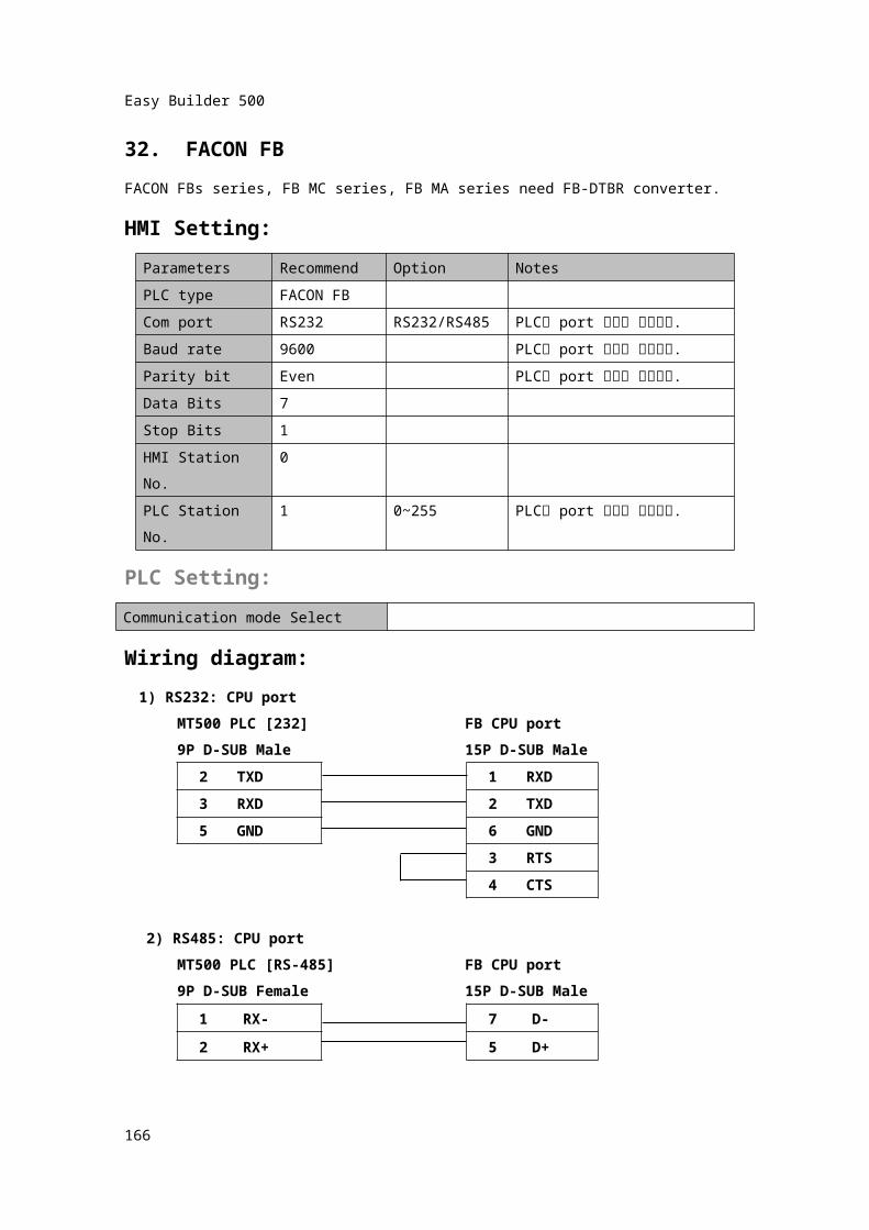
32. FACON FBFACON FBs series, FB MC series, FB MA series need FB-DTBR converter.HMI Setting:
Parameters Recommend Option NotesPLC type FACON FBCom port RS232 RS232/RS485 PLC의 port 셋팅과 일치시킴.Baud rate 9600 PLC의 port 셋팅과 일치시킴.Parity bit Even PLC의 port 셋팅과 일치시킴.Data Bits 7Stop Bits 1HMI Station No. 0PLC Station No. 1 0~255 PLC의 port 셋팅과 일치시킴.
PLC Setting:Communication mode SelectWiring diagram:
1) RS232: CPU portMT500 PLC [232] FB CPU port9P D-SUB Male 15P D-SUB Male
2 TXD 1 RXD3 RXD 2 TXD
5 GND 6 GND3 RTS4 CTS
2) RS485: CPU portMT500 PLC [RS-485] FB CPU port9P D-SUB Female 15P D-SUB Male
1 RX- 7 D-2 RX+ 5 D+
163
Easy Builder 500
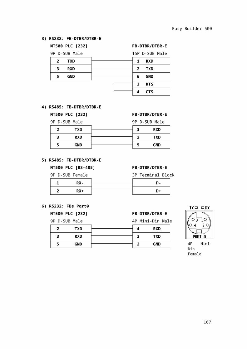
3) RS232: FB-DTBR/DTBR-EMT500 PLC [232] FB-DTBR/DTBR-E9P D-SUB Male 15P D-SUB Male
2 TXD 1 RXD3 RXD 2 TXD
5 GND 6 GND3 RTS4 CTS
4) RS485: FB-DTBR/DTBR-EMT500 PLC [232] FB-DTBR/DTBR-E9P D-SUB Male 9P D-SUB Male
2 TXD 3 RXD3 RXD 2 TXD5 GND 5 GND
5) RS485: FB-DTBR/DTBR-EMT500 PLC [RS-485] FB-DTBR/DTBR-E9P D-SUB Female 3P Terminal Block
1 RX- D-2 RX+ D+
6) RS232: FBs Port0MT500 PLC [232] FB-DTBR/DTBR-E9P D-SUB Male 4P Mini-Din Male
2 TXD 4 RXD
3 RXD 3
TXD
5 GND 2 GND
164
4P Mini-DinFemale
Easy Builder 500
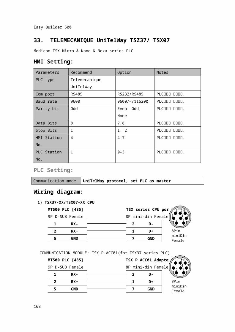
33. TELEMECANIQUE UniTelWay TSZ37/ TSX07Modicon TSX Micro & Nano & Neza series PLCHMI Setting:Parameters Recommend Option NotesPLC type Telemecanique
UniTelWayCom port RS485 RS232/RS485 PLC설정과 일치시킴.Baud rate 9600 9600/~/115200 PLC설정과 일치시킴.Parity bit Odd Even, Odd, None PLC설정과 일치시킴.Data Bits 8 7,8 PLC설정과 일치시킴.Stop Bits 1 1, 2 PLC설정과 일치시킴.HMI Station No. 4 4-7 PLC설정과 일치시킴.PLC Station No. 1 0-3 PLC설정과 일치시킴.
PLC Setting:Communication mode UniTelWay protocol, set PLC as master
Wiring diagram:1) TSX37-XX/TSX07-XX CPU
MT500 PLC [485] TSX series CPU port9P D-SUB Female 8P mini-din Female
1 RX- 2
D-
2 RX+ 1 D+5 GND 7 GND
COMMUNICATION MODULE: TSX P ACC01(for TSX37 series PLC)MT500 PLC [485] TSX P ACC01 Adapter9P D-SUB Female 8P mini-din Female
1 RX- 2
D-
2 RX+ 1 D+5 GND 7 GND
165
8Pin miniDinFemale
8Pin miniDinFemale
Easy Builder 500
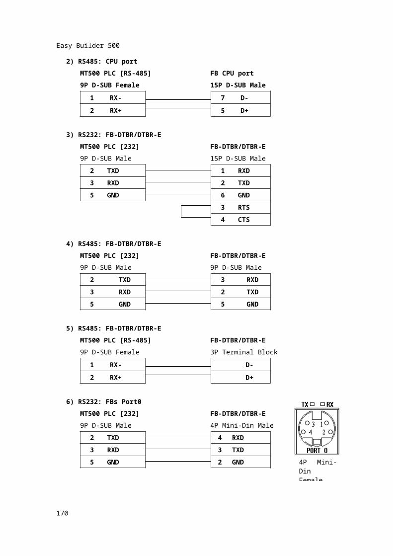
2) RS485: CPU portMT500 PLC [RS-485] FB CPU port9P D-SUB Female 15P D-SUB Male
1 RX- 7 D-2 RX+ 5 D+
3) RS232: FB-DTBR/DTBR-EMT500 PLC [232] FB-DTBR/DTBR-E9P D-SUB Male 15P D-SUB Male
2 TXD 1 RXD3 RXD 2 TXD
5 GND 6 GND3 RTS4 CTS
4) RS485: FB-DTBR/DTBR-EMT500 PLC [232] FB-DTBR/DTBR-E9P D-SUB Male 9P D-SUB Male
2 TXD 3 RXD3 RXD 2 TXD5 GND 5 GND
5) RS485: FB-DTBR/DTBR-EMT500 PLC [RS-485] FB-DTBR/DTBR-E9P D-SUB Female 3P Terminal Block
1 RX- D-2 RX+ D+
6) RS232: FBs Port0MT500 PLC [232] FB-DTBR/DTBR-E9P D-SUB Male 4P Mini-Din Male
2 TXD 4 RXD
166
Easy Builder 500
3 RXD 3
TXD
5 GND 2 GND
167
4P Mini-DinFemale
Easy Builder 500
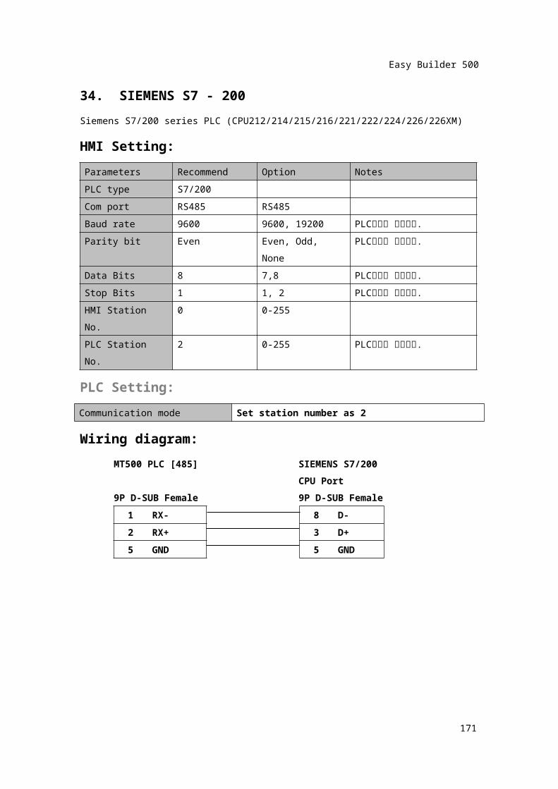
34. SIEMENS S7 - 200Siemens S7/200 series PLC (CPU212/214/215/216/221/222/224/226/226XM)HMI Setting:Parameters Recommend Option NotesPLC type S7/200Com port RS485 RS485Baud rate 9600 9600, 19200 PLC설정과 일치시킴.Parity bit Even Even, Odd, None PLC설정과 일치시킴.Data Bits 8 7,8 PLC설정과 일치시킴.Stop Bits 1 1, 2 PLC설정과 일치시킴.HMI Station No. 0 0-255PLC Station No. 2 0-255 PLC설정과 일치시킴.
PLC Setting:Communication mode Set station number as 2
Wiring diagram:MT500 PLC [485] SIEMENS S7/200
CPU Port9P D-SUB Female 9P D-SUB Female
1 RX- 8 D-2 RX+ 3 D+5 GND 5 GND
168

Easy Builder 500
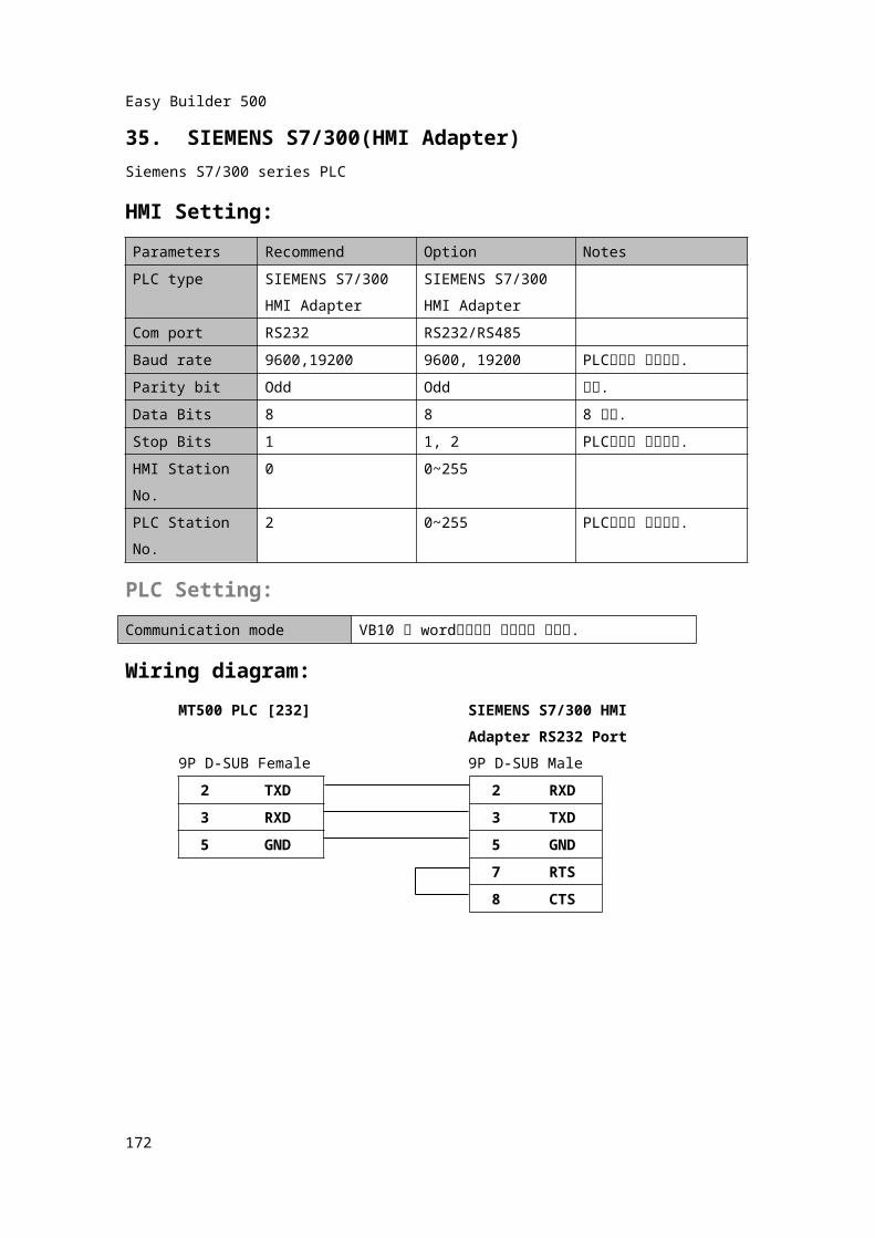
35. SIEMENS S7/300(HMI Adapter)Siemens S7/300 series PLCHMI Setting:Parameters Recommend Option NotesPLC type SIEMENS S7/300
HMI AdapterSIEMENS S7/300 HMI Adapter
Com port RS232 RS232/RS485Baud rate 9600,19200 9600, 19200 PLC설정과 일치시킴.Parity bit Odd Odd 고정.Data Bits 8 8 8 고정.Stop Bits 1 1, 2 PLC설정과 일치시킴.HMI Station No. 0 0~255PLC Station No. 2 0~255 PLC설정과 일치시킴.
PLC Setting:Communication mode VB10 을 word영역으로 설정하여 사용함.Wiring diagram:
MT500 PLC [232] SIEMENS S7/300 HMIAdapter RS232 Port
9P D-SUB Female 9P D-SUB Male2 TXD 2 RXD3 RXD 3 TXD
5 GND 5 GND7 RTS8 CTS
169
Easy Builder 500
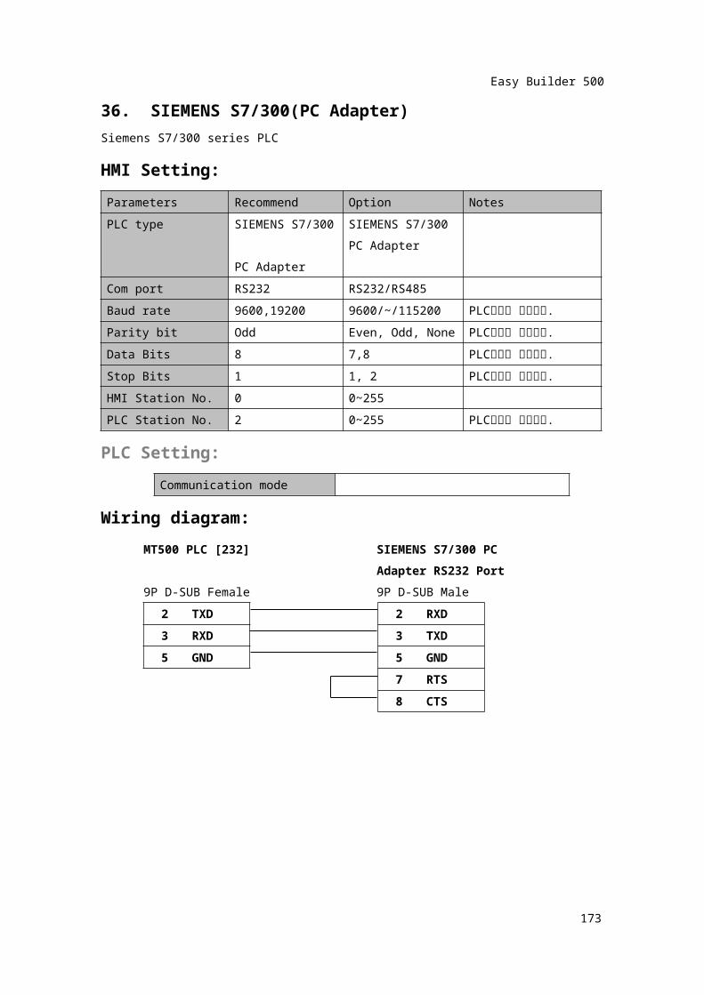
36. SIEMENS S7/300(PC Adapter)Siemens S7/300 series PLCHMI Setting:Parameters Recommend Option NotesPLC type SIEMENS S7/300
PC AdapterSIEMENS S7/300 PC Adapter
Com port RS232 RS232/RS485Baud rate 9600,19200 9600/~/115200 PLC설정과 일치시킴.Parity bit Odd Even, Odd, None PLC설정과 일치시킴.Data Bits 8 7,8 PLC설정과 일치시킴.Stop Bits 1 1, 2 PLC설정과 일치시킴.HMI Station No. 0 0~255PLC Station No. 2 0~255 PLC설정과 일치시킴.
PLC Setting:Communication mode
Wiring diagram:MT500 PLC [232] SIEMENS S7/300 PC
Adapter RS232 Port9P D-SUB Female 9P D-SUB Male
2 TXD 2 RXD3 RXD 3 TXD
5 GND 5 GND7 RTS8 CTS
170
Easy Builder 500
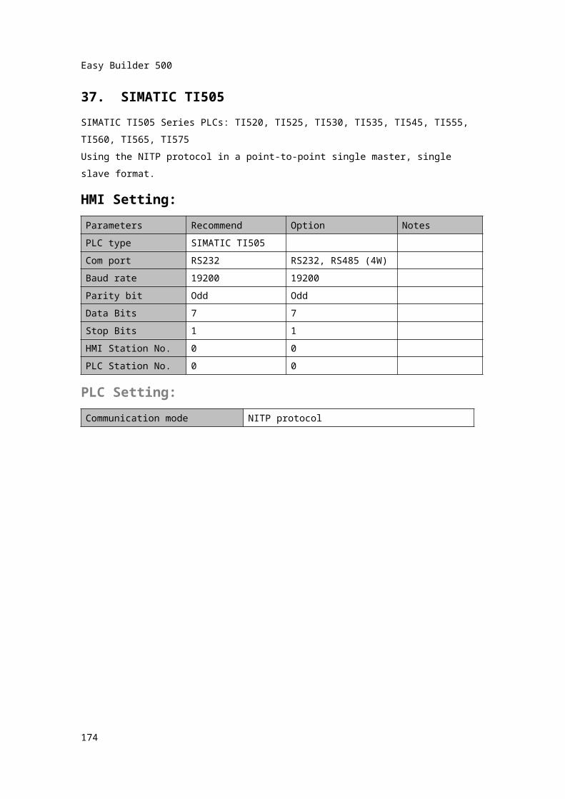
37. SIMATIC TI505SIMATIC TI505 Series PLCs: TI520, TI525, TI530, TI535, TI545, TI555, TI560, TI565, TI575Using the NITP protocol in a point-to-point single master, single slave format.HMI Setting:Parameters Recommend Option NotesPLC type SIMATIC TI505Com port RS232 RS232, RS485 (4W)Baud rate 19200 19200Parity bit Odd OddData Bits 7 7Stop Bits 1 1HMI Station No. 0 0PLC Station No. 0 0
PLC Setting:Communication mode NITP protocol
171
Easy Builder 500
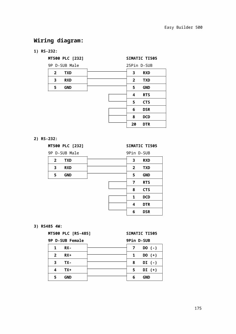
Wiring diagram:1) RS-232:
MT500 PLC [232] SIMATIC TI5059P D-SUB Male 25Pin D-SUB
2 TXD 3 RXD3 RXD 2 TXD
5 GND 5 GND4 RTS5 CTS6 DSR8 DCD
20 DTR
2) RS-232:MT500 PLC [232] SIMATIC TI5059P D-SUB Male 9Pin D-SUB
2 TXD 3 RXD3 RXD 2 TXD
5 GND 5 GND7 RTS8 CTS1 DCD4 DTR6 DSR
3) RS485 4W:MT500 PLC [RS-485] SIMATIC TI505
172
Easy Builder 500
9P D-SUB Female 9Pin D-SUB1 RX- 7 DO (-)2 RX+ 1 DO (+)3 TX- 8 DI (-)4 TX+ 5 DI (+)5 GND 6 GND
173
Easy Builder 500
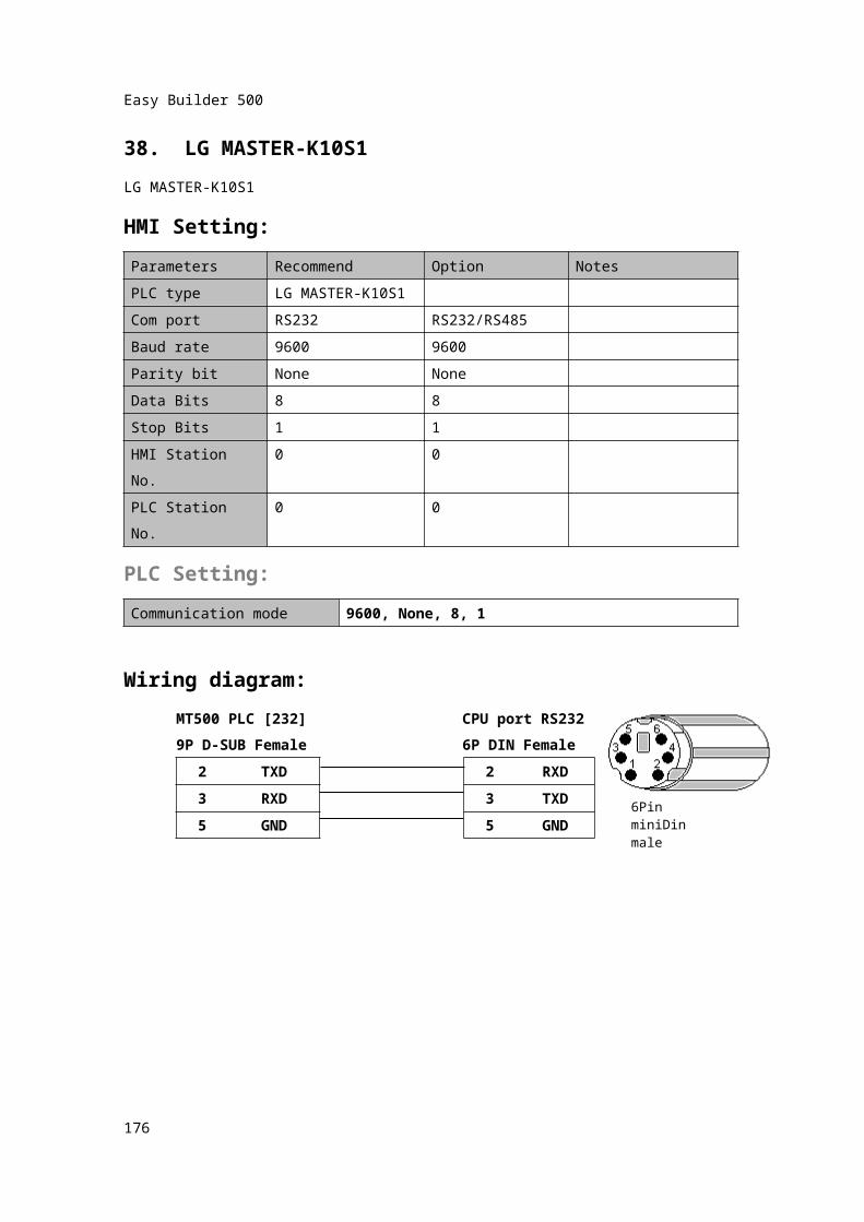
38. LG MASTER-K10S1LG MASTER-K10S1HMI Setting:Parameters Recommend Option NotesPLC type LG MASTER-K10S1Com port RS232 RS232/RS485Baud rate 9600 9600Parity bit None NoneData Bits 8 8Stop Bits 1 1HMI Station No. 0 0PLC Station No. 0 0
PLC Setting:Communication mode 9600, None, 8, 1
Wiring diagram:MT500 PLC [232] CPU port RS2329P D-SUB Female 6P DIN Female
2 TXD 2 RXD
3 RXD 3
TXD
5 GND 5 GND
174
6Pin miniDinmale
Easy Builder 500
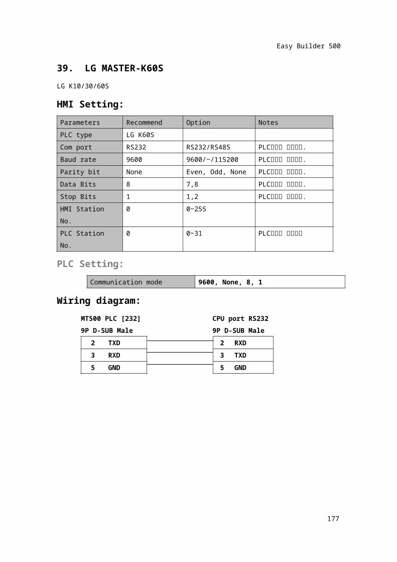
39. LG MASTER-K60SLG K10/30/60SHMI Setting:Parameters Recommend Option NotesPLC type LG K60SCom port RS232 RS232/RS485 PLC설정과 일치시킴.Baud rate 9600 9600/~/115200 PLC설정과 일치시킴.Parity bit None Even, Odd, None PLC설정과 일치시킴.Data Bits 8 7,8 PLC설정과 일치시킴.Stop Bits 1 1,2 PLC설정과 일치시킴.HMI Station No. 0 0~255PLC Station No. 0 0~31 PLC설정과 일치시킴
PLC Setting:Communication mode 9600, None, 8, 1
Wiring diagram:MT500 PLC [232] CPU port RS2329P D-SUB Male 9P D-SUB Male
2 TXD 2 RXD3 RXD 3 TXD5 GND 5 GND
175
Easy Builder 500
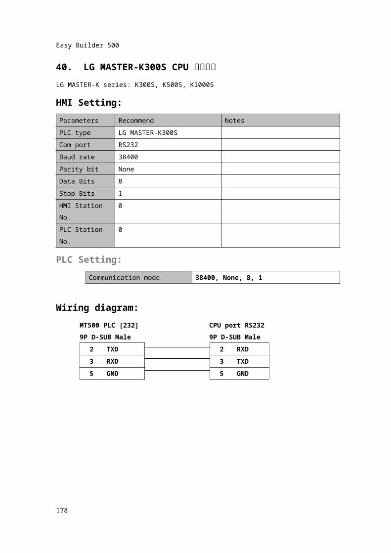
40. LG MASTER-K300S CPU 직결통신LG MASTER-K series: K300S, K500S, K1000SHMI Setting:Parameters Recommend NotesPLC type LG MASTER-K300SCom port RS232Baud rate 38400Parity bit NoneData Bits 8Stop Bits 1HMI Station No. 0PLC Station No. 0
PLC Setting:Communication mode 38400, None, 8, 1
Wiring diagram:MT500 PLC [232] CPU port RS2329P D-SUB Male 9P D-SUB Male
2 TXD 2 RXD3 RXD 3 TXD5 GND 5 GND
176
Easy Builder 500
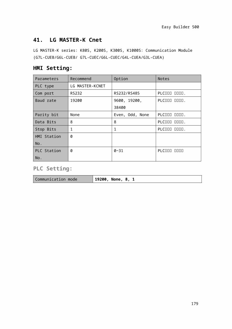
41. LG MASTER-K CnetLG MASTER-K series: K80S, K200S, K300S, K1000S: Communication Module (G7L-CUEB/G6L-CUEB/ G7L-CUEC/G6L-CUEC/G4L-CUEA/G3L-CUEA)HMI Setting:Parameters Recommend Option NotesPLC type LG MASTER-KCNETCom port RS232 RS232/RS485 PLC설정과 일치시킴.Baud rate 19200 9600, 19200, 38400 PLC설정과 일치시킴.Parity bit None Even, Odd, None PLC설정과 일치시킴.Data Bits 8 8 PLC설정과 일치시킴.Stop Bits 1 1 PLC설정과 일치시킴.HMI Station No. 0PLC Station No. 0 0~31 PLC설정과 일치시킴
PLC Setting:Communication mode 19200, None, 8, 1
177
Easy Builder 500
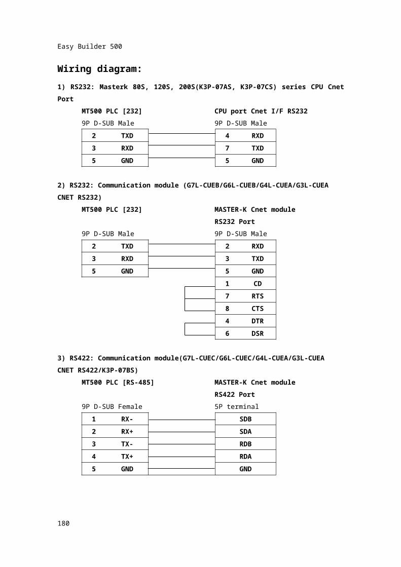
Wiring diagram:1) RS232: Masterk 80S, 120S, 200S(K3P-07AS, K3P-07CS) series CPU Cnet Port
MT500 PLC [232] CPU port Cnet I/F RS2329P D-SUB Male 9P D-SUB Male
2 TXD 4 RXD3 RXD 7 TXD5 GND 5 GND
2) RS232: Communication module (G7L-CUEB/G6L-CUEB/G4L-CUEA/G3L-CUEACNET RS232)
MT500 PLC [232] MASTER-K Cnet moduleRS232 Port
9P D-SUB Male 9P D-SUB Male2 TXD 2 RXD3 RXD 3 TXD
5 GND
5 GND1 CD7 RTS8 CTS4 DTR6 DSR
3) RS422: Communication module(G7L-CUEC/G6L-CUEC/G4L-CUEA/G3L-CUEACNET RS422/K3P-07BS)
MT500 PLC [RS-485] MASTER-K Cnet moduleRS422 Port
9P D-SUB Female 5P terminal
178
Easy Builder 500
1
RX-
SDB2 RX+ SDA3 TX- RDB4 TX+ RDA5 GND GND
179
Easy Builder 500
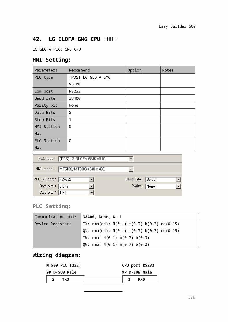
42. LG GLOFA GM6 CPU 직결통신LG GLOFA PLC: GM6 CPUHMI Setting:Parameters Recommend Option NotesPLC type [PDS] LG GLOFA GM6 V3.00Com port RS232Baud rate 38400Parity bit NoneData Bits 8Stop Bits 1HMI Station No. 0PLC Station No. 0
PLC Setting:Communication mode 38400, None, 8, 1Device Register: IX: nmb(dd): N(0-1) m(0-7) b(0-3) dd(0-15)
QX: nmb(dd): N(0-1) m(0-7) b(0-3) dd(0-15)IW: nmb: N(0-1) m(0-7) b(0-3)QW: nmb: N(0-1) m(0-7) b(0-3)
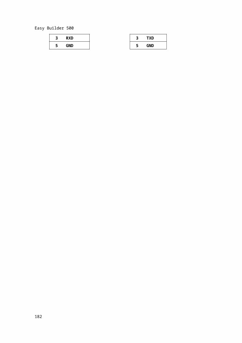
Wiring diagram:MT500 PLC [232] CPU port RS2329P D-SUB Male 9P D-SUB Male
2 TXD 2 RXD3 RXD 3 TXD5 GND 5 GND
180
Easy Builder 500
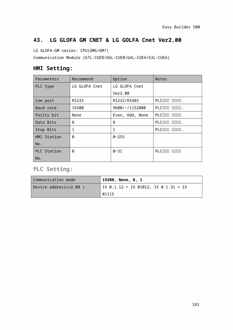
43. LG GLOFA GM CNET & LG GOLFA Cnet Ver2.00LG GLOFA-GM series: CPU(GM6/GM7)Communication Module (G7L-CUEB/G6L-CUEB/G4L-CUEA/G3L-CUEA)HMI Setting:Parameters Recommend Option NotesPLC type LG GLOFA Cnet LG GLOFA Cnet
Ver2.00Com port RS232 RS232/RS485 PLC설정과 일치시킴.Baud rate 19200 9600/~/1152000 PLC설정과 일치시킴.Parity bit None Even, Odd, None PLC설정과 일치시킴.Data Bits 8 8 PLC설정과 일치시킴.Stop Bits 1 1 PLC설정과 일치시킴.HMI Station No. 0 0~255PLC Station No. 0 0~31 PLC설정과 일치시킴
PLC Setting:Communication mode 19200, None, 8, 1Device address(v2.00 ) IX 0.1.12 = IX 01012, IX 0.1.31 = IX 01115
181
Easy Builder 500
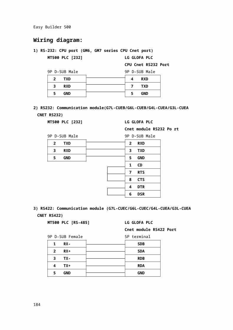
Wiring diagram:1) RS-232: CPU port (GM6, GM7 series CPU Cnet port)
MT500 PLC [232] LG GLOFA PLCCPU Cnet RS232 Port
9P D-SUB Male 9P D-SUB Male 2 TXD 4 RXD3 RXD 7 TXD5 GND 5 GND
2) RS232: Communication module(G7L-CUEB/G6L-CUEB/G4L-CUEA/G3L-CUEACNET RS232)
MT500 PLC [232] LG GLOFA PLCCnet module RS232 Po rt
9P D-SUB Male 9P D-SUB Male2 TXD 2 RXD3 RXD 3 TXD
5 GND 5 GND1 CD7 RTS8 CTS4 DTR6 DSR
3) RS422: Communication module (G7L-CUEC/G6L-CUEC/G4L-CUEA/G3L-CUEACNET RS422)
MT500 PLC [RS-485] LG GLOFA PLCCnet module RS422 Port
9P D-SUB Female 5P terminal
182
Easy Builder 500
1
RX-
SDB2 RX+ SDA3 TX- RDB4 TX+ RDA5 GND GND
183
Easy Builder 500
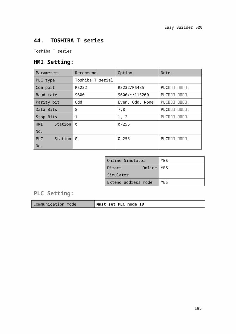
44. TOSHIBA T seriesToshiba T seriesHMI Setting:Parameters Recommend Option NotesPLC type Toshiba T serialCom port RS232 RS232/RS485 PLC설정과 일치시킴.Baud rate 9600 9600/~/115200 PLC설정과 일치시킴.Parity bit Odd Even, Odd, None PLC설정과 일치시킴.Data Bits 8 7,8 PLC설정과 일치시킴.Stop Bits 1 1, 2 PLC설정과 일치시킴.HMI Station No. 0 0-255PLC Station No. 0 0-255 PLC설정과 일치시킴.
Online Simulator YESDirect Online Simulator YESExtend address mode YES
PLC Setting:Communication mode Must set PLC node ID
184
Easy Builder 500
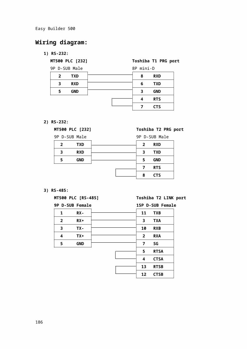
Wiring diagram:1) RS-232:
MT500 PLC [232] Toshiba T1 PRG port9P D-SUB Male 8P mini-D
2 TXD 8 RXD3 RXD 6 TXD
5 GND 3 GND4 RTS7 CTS
2) RS-232:MT500 PLC [232] Toshiba T2 PRG port9P D-SUB Male 9P D-SUB Male
2 TXD 2 RXD3 RXD 3 TXD
5 GND 5 GND7 RTS8 CTS
3) RS-485:MT500 PLC [RS-485] Toshiba T2 LINK port9P D-SUB Female 15P D-SUB Female
1 RX- 11 TXB2 RX+ 3 TXA3 TX- 10 RXB4 TX+ 2 RXA
5 GND 7
SG
5 RTSA4 CTSA
185
Easy Builder 500
13 RTSB12 CTSB
186
Easy Builder 500
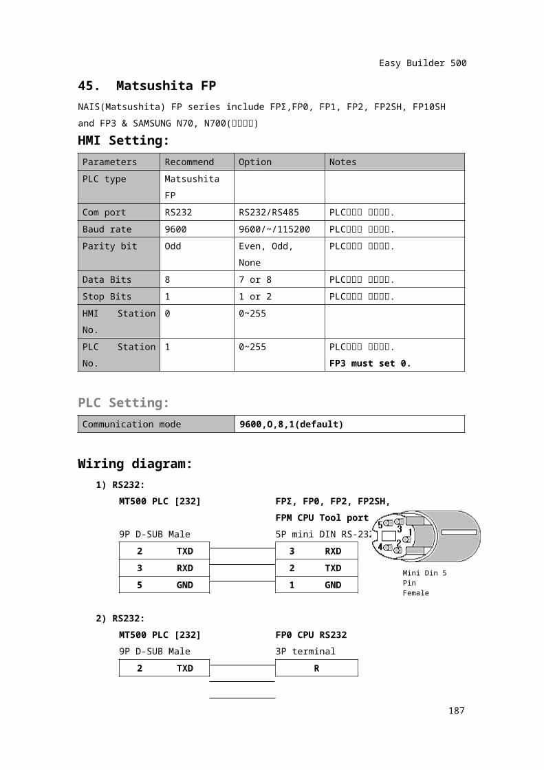
45. Matsushita FPNAIS(Matsushita) FP series include FPΣ,FP0, FP1, FP2, FP2SH, FP10SH and FP3 & SAMSUNG N70, N700(알파계열)HMI Setting:Parameters Recommend Option NotesPLC type Matsushita FPCom port RS232 RS232/RS485 PLC설정과 일치시킴.Baud rate 9600 9600/~/115200 PLC설정과 일치시킴.Parity bit Odd Even, Odd, None PLC설정과 일치시킴.Data Bits 8 7 or 8 PLC설정과 일치시킴.Stop Bits 1 1 or 2 PLC설정과 일치시킴.HMI Station No. 0 0~255PLC Station No. 1 0~255 PLC설정과 일치시킴.
FP3 must set 0.
PLC Setting:Communication mode 9600,O,8,1(default)
Wiring diagram:1) RS232:
MT500 PLC [232] FPΣ, FP0, FP2, FP2SH,FPM CPU Tool port
9P D-SUB Male 5P mini DIN RS-2322 TXD 3 RXD
3 RXD2
TXD
5 GND 1 GND
2) RS232:MT500 PLC [232] FP0 CPU RS2329P D-SUB Male 3P terminal
2 TXD R3 RXD S5 GND G
187
Mini Din 5 PinFemale

Easy Builder 500
188
Easy Builder 500
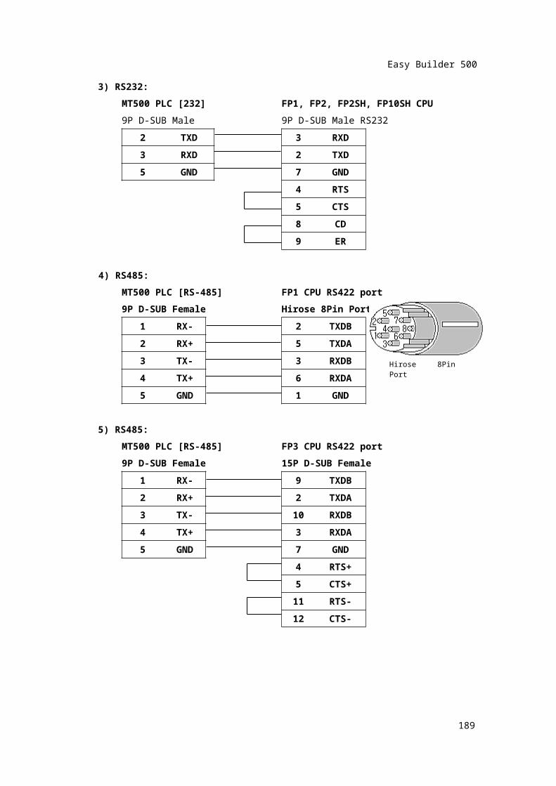
3) RS232:MT500 PLC [232] FP1, FP2, FP2SH, FP10SH CPU9P D-SUB Male 9P D-SUB Male RS232
2 TXD 3 RXD3 RXD 2 TXD
5 GND 7 GND
4 RTS5 CTS8 CD9 ER
4) RS485:MT500 PLC [RS-485] FP1 CPU RS422 port9P D-SUB Female Hirose 8Pin Port
1 RX- 2 TXDB2 RX+ 5 TXDA
3 TX- 3RXDB
4 TX+ 6 RXDA5 GND 1 GND
5) RS485:MT500 PLC [RS-485] FP3 CPU RS422 port9P D-SUB Female 15P D-SUB Female
1 RX- 9 TXDB2 RX+ 2 TXDA3 TX- 10 RXDB4 TX+ 3 RXDA
5 GND
7
GND
189
Hirose 8Pin Port
Easy Builder 500
4 RTS+5 CTS+
11 RTS-12 CTS-
190
Easy Builder 500
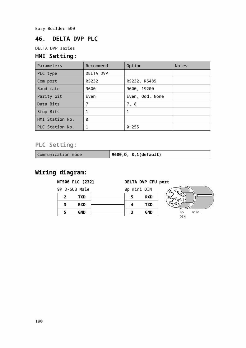
46. DELTA DVP PLCDELTA DVP seriesHMI Setting:Parameters Recommend Option NotesPLC type DELTA DVPCom port RS232 RS232, RS485Baud rate 9600 9600, 19200Parity bit Even Even, Odd, NoneData Bits 7 7, 8Stop Bits 1 1HMI Station No. 0PLC Station No. 1 0~255
PLC Setting:Communication mode 9600,O, 8,1(default)
Wiring diagram:MT500 PLC [232] DELTA DVP CPU port9P D-SUB Male 8p mini DIN
2 TXD 5 RXD3 RXD 4 TXD
5 GND 3 GND
191
8p mini DIN
Easy Builder 500
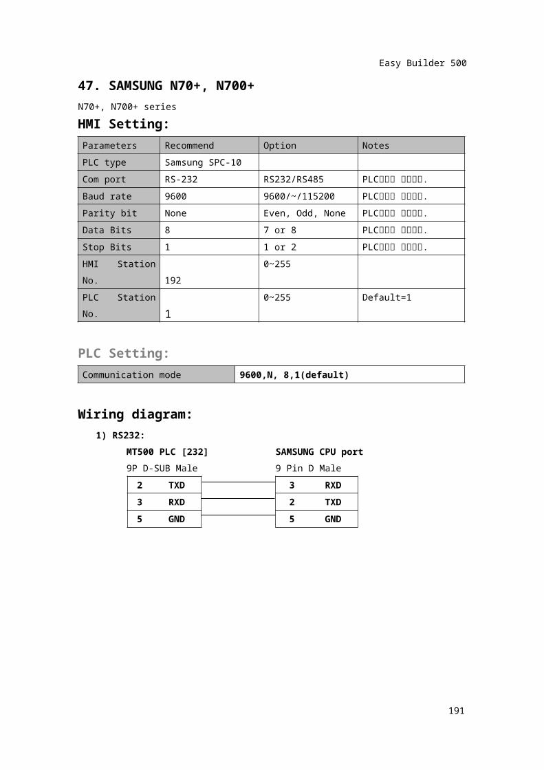
47. SAMSUNG N70+, N700+N70+, N700+ seriesHMI Setting:Parameters Recommend Option NotesPLC type Samsung SPC-10Com port RS-232 RS232/RS485 PLC설정과 일치시킴.Baud rate 9600 9600/~/115200 PLC설정과 일치시킴.Parity bit None Even, Odd, None PLC설정과 일치시킴.Data Bits 8 7 or 8 PLC설정과 일치시킴.Stop Bits 1 1 or 2 PLC설정과 일치시킴.HMI Station No. 192 0~255PLC Station No. 1 0~255 Default=1
PLC Setting:Communication mode 9600,N, 8,1(default)
Wiring diagram:1) RS232:
MT500 PLC [232] SAMSUNG CPU port9P D-SUB Male 9 Pin D Male
2 TXD 3 RXD3 RXD 2 TXD5 GND 5 GND
192
Easy Builder 500
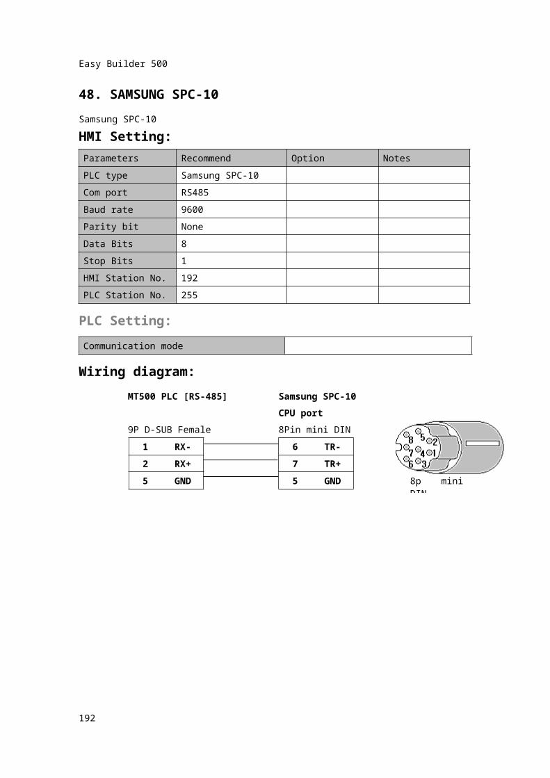
48. SAMSUNG SPC-10Samsung SPC-10HMI Setting:Parameters Recommend Option NotesPLC type Samsung SPC-10Com port RS485Baud rate 9600Parity bit NoneData Bits 8Stop Bits 1HMI Station No. 192PLC Station No. 255
PLC Setting:Communication mode
Wiring diagram:MT500 PLC [RS-485] Samsung SPC-10
CPU port9P D-SUB Female 8Pin mini DIN
1 RX- 6 TR-
2 RX+ 7TR+
5 GND 5 GND
193
8p mini DIN
Easy Builder 500
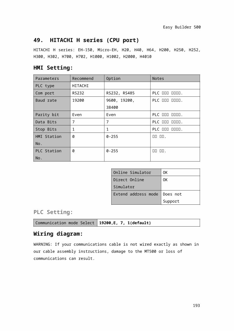
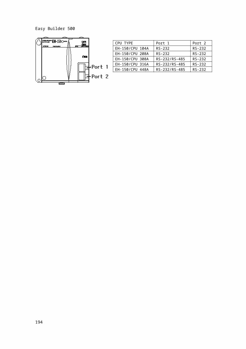
49. HITACHI H series (CPU port)HITACHI H series: EH-150, Micro-EH, H20, H40, H64, H200, H250, H252, H300, H302, H700, H702, H1000, H1002, H2000, H4010HMI Setting:Parameters Recommend Option NotesPLC type HITACHICom port RS232 RS232, RS485 PLC 설정과 일치시킴.Baud rate 19200 9600, 19200, 38400 PLC 설정과 일치시킴.Parity bit Even Even PLC 설정과 일치시킴.Data Bits 7 7 PLC 설정과 일치시킴.Stop Bits 1 1 PLC 설정과 일치시킴.HMI Station No. 0 0-255 설정 없음.PLC Station No. 0 0-255 설정 없음.
Online Simulator OKDirect Online Simulator
OK
Extend address mode Does not SupportPLC Setting:Communication mode Select 19200,E, 7, 1(default)
Wiring diagram:WARNING: If your communications cable is not wired exactly as shown in our cable assembly instructions, damage to the MT500 or loss of communications can result.
194
CPU TYPE Port 1 Port 2EH-150/CPU 104A RS-232 RS-232EH-150/CPU 208A RS-232 RS-232EH-150/CPU 308A RS-232/RS-485 RS-232EH-150/CPU 316A RS-232/RS-485 RS-232EH-150/CPU 448A RS-232/RS-485 RS-232
Easy Builder 500
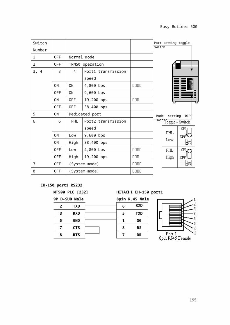
Switch Number
1 OFF Normal mode2 OFF TRNS0 operation3, 4 3 4 Port1 transmission
speedON ON 4,800 bps 지원안함
OFF ON 9,600 bpsON OFF 19,200 bps 기본값
OFF OFF 38,400 bps5 ON Dedicated port6 6 PHL Port2 transmission
speedON Low 9,600 bpsON High 38,400 bpsOFF Low 4,800 bps 지원안함
OFF High 19,200 bps 기본값
7 OFF (System mode) 변경안함
8 OFF (System mode) 변경안함
195
Port setting toggle - switch
Mode setting DIP-switch
Easy Builder 500
EH-150 port1 RS232MT500 PLC [232] HITACHI EH-150 port19P D-SUB Male 8pin RJ45 Male
2 TXD 6 RXD
3 RXD 5 TXD5 GND 1 SG7 CTS 8 RS
8 RTS 7 DR
196
Easy Builder 500
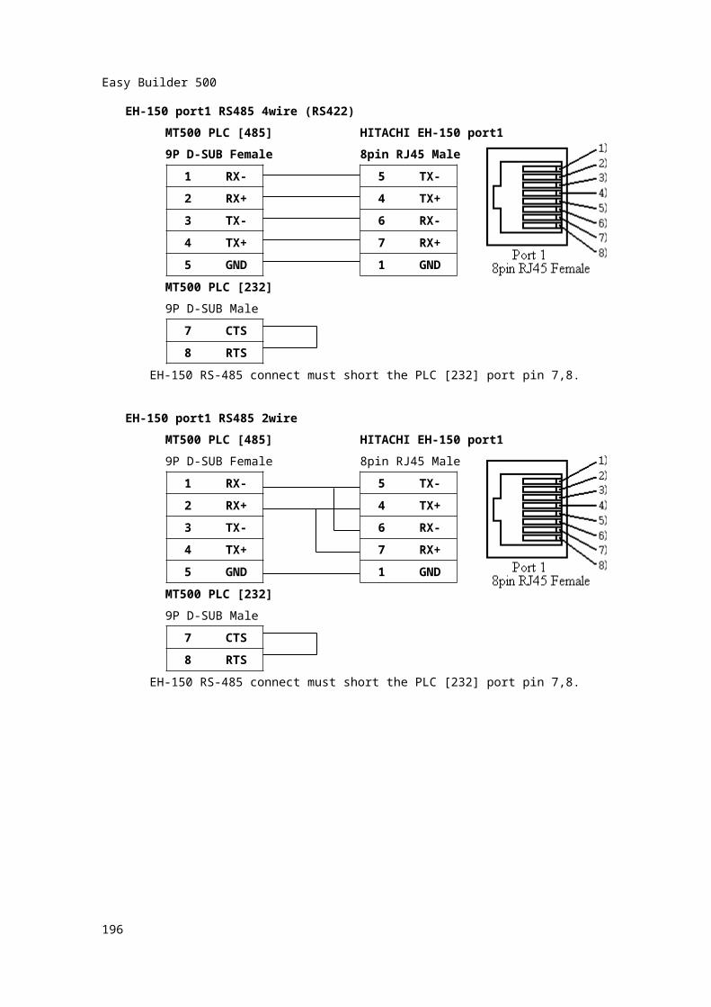
EH-150 port1 RS485 4wire (RS422)MT500 PLC [485] HITACHI EH-150 port19P D-SUB Female 8pin RJ45 Male
1 RX- 5 TX-2 RX+ 4 TX+3 TX- 6 RX-4 TX+ 7 RX+
5 GND 1 GNDMT500 PLC [232]9P D-SUB Male
7 CTS
8 RTSEH-150 RS-485 connect must short the PLC [232] port pin 7,8.
EH-150 port1 RS485 2wireMT500 PLC [485] HITACHI EH-150 port19P D-SUB Female 8pin RJ45 Male
1 RX- 5 TX-2 RX+ 4 TX+3 TX- 6 RX-4 TX+ 7 RX+
5 GND 1 GNDMT500 PLC [232]9P D-SUB Male
7 CTS
8 RTSEH-150 RS-485 connect must short the PLC [232] port pin 7,8.
197
Easy Builder 500
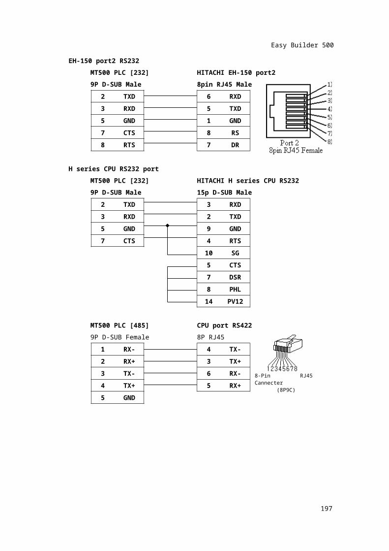
EH-150 port2 RS232MT500 PLC [232] HITACHI EH-150 port29P D-SUB Male 8pin RJ45 Male
2 TXD 6 RXD3 RXD 5 TXD5 GND 1 GND7 CTS 8 RS
8 RTS 7 DR
H series CPU RS232 portMT500 PLC [232] HITACHI H series CPU RS2329P D-SUB Male 15p D-SUB Male
2 TXD 3 RXD3 RXD 2 TXD5 GND 9 GND
7 CTS 4 RTS
10 SG5 CTS7 DSR8 PHL
14 PV12
MT500 PLC [485] CPU port RS4229P D-SUB Female 8P RJ45
1 RX- 4 TX-2 RX+ 3 TX+3 TX- 6 RX-
4 TX+ 5 RX+5 GND
198
8-Pin RJ45 Cannecter (8P9C)
Easy Builder 500
199
Easy Builder 500
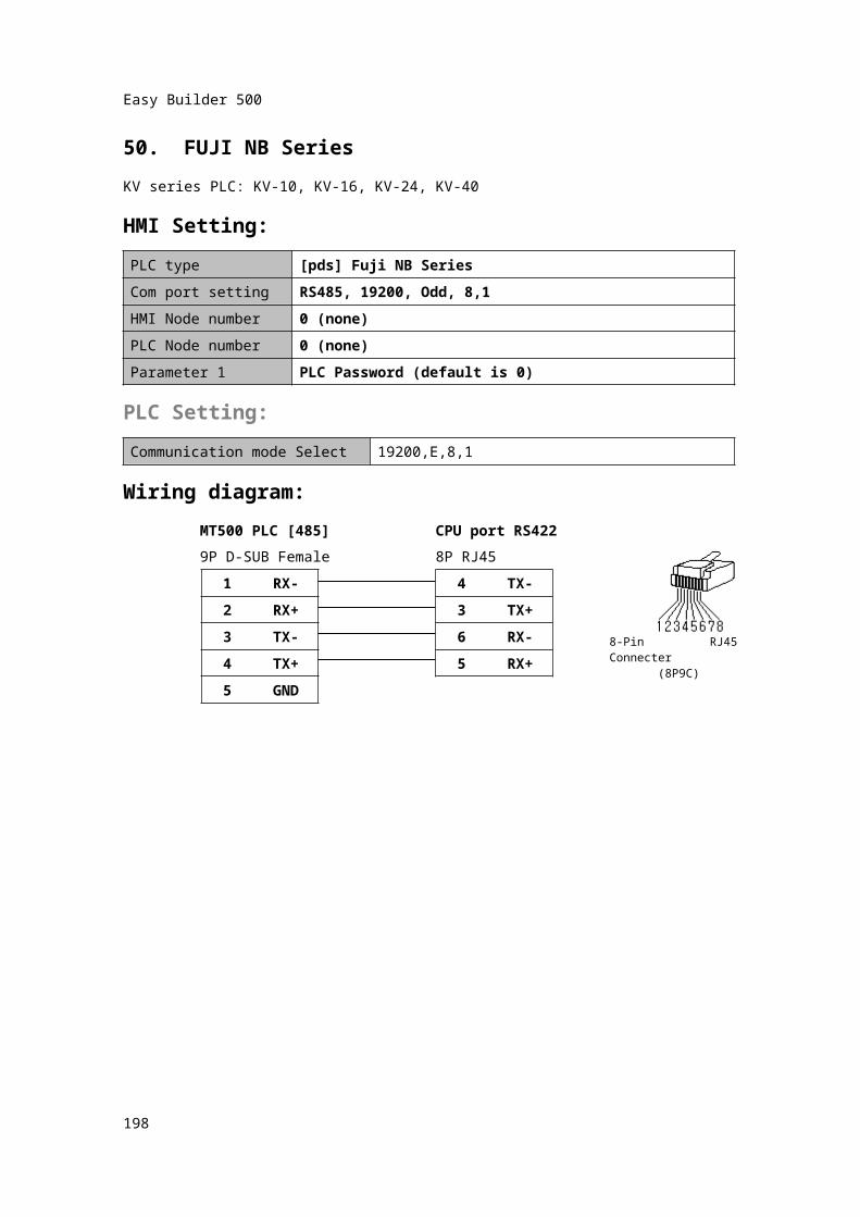
50. FUJI NB SeriesKV series PLC: KV-10, KV-16, KV-24, KV-40HMI Setting:PLC type [pds] Fuji NB SeriesCom port setting RS485, 19200, Odd, 8,1HMI Node number 0 (none)PLC Node number 0 (none)Parameter 1 PLC Password (default is 0)
PLC Setting:Communication mode Select 19200,E,8,1
Wiring diagram:MT500 PLC [485] CPU port RS4229P D-SUB Female 8P RJ45
1 RX- 4 TX-2 RX+ 3 TX+3 TX- 6 RX-
4 TX+ 5 RX+5 GND
200
8-Pin RJ45 Connecter (8P9C)
Easy Builder 500
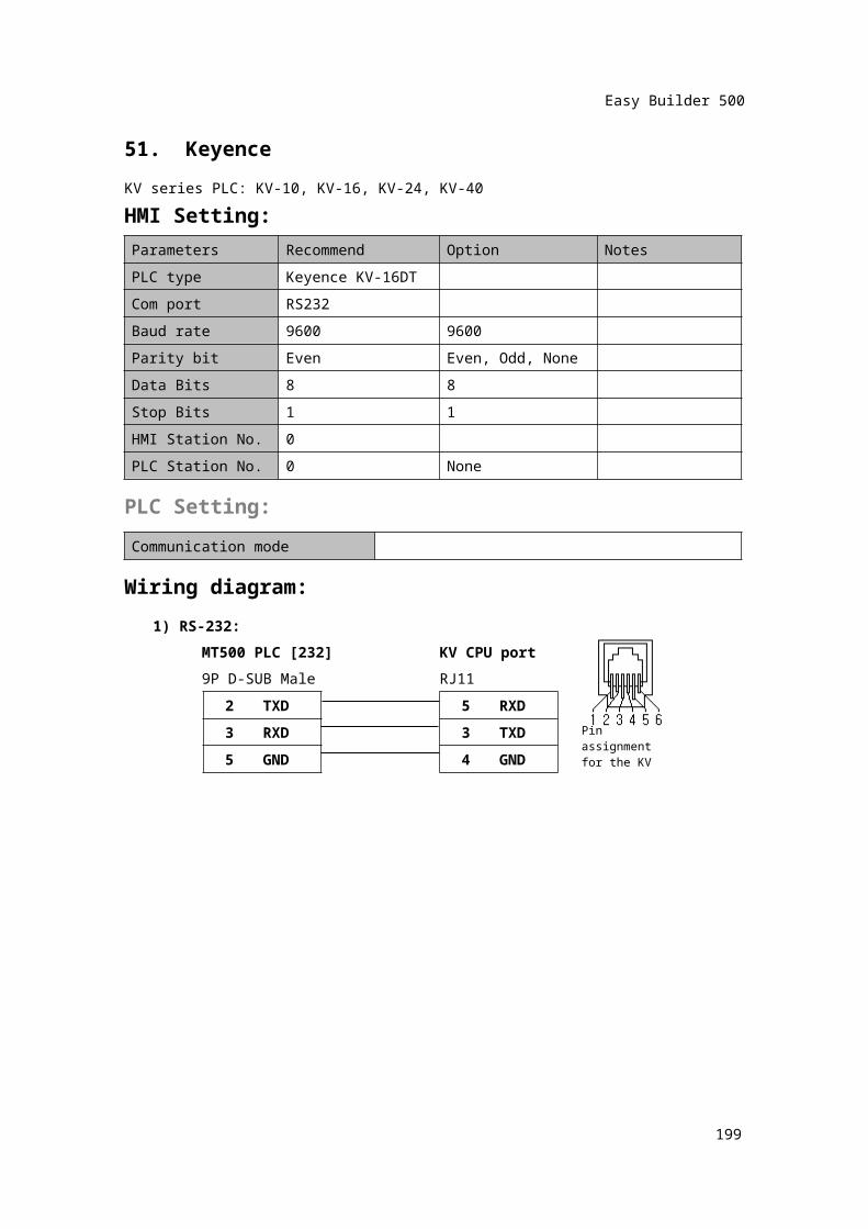
51. KeyenceKV series PLC: KV-10, KV-16, KV-24, KV-40HMI Setting:Parameters Recommend Option NotesPLC type Keyence KV-16DTCom port RS232Baud rate 9600 9600Parity bit Even Even, Odd, NoneData Bits 8 8Stop Bits 1 1HMI Station No. 0PLC Station No. 0 None
PLC Setting:Communication mode
Wiring diagram:1) RS-232:
MT500 PLC [232] KV CPU port9P D-SUB Male RJ11
2 TXD 5
RXD
3 RXD 3 TXD5 GND 4 GND
201
Pin assignmentfor the KV
Easy Builder 500
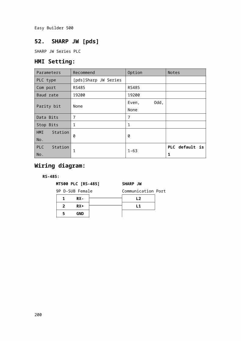
52. SHARP JW [pds]SHARP JW Series PLCHMI Setting:Parameters Recommend Option NotesPLC type [pds]Sharp JW SeriesCom port RS485 RS485Baud rate 19200 19200Parity bit None Even, Odd, NoneData Bits 7 7Stop Bits 1 1HMI Station No. 0 0PLC Station No. 1 1-63 PLC default is 1
Wiring diagram:RS-485:
MT500 PLC [RS-485] SHARP JW9P D-SUB Female Communication Port
1 RX- L22 RX+ L15 GND
202

Easy Builder 500
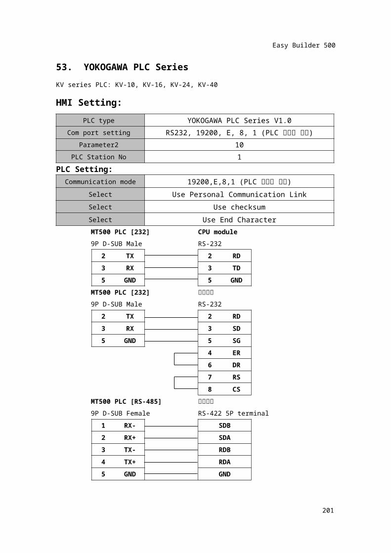
53. YOKOGAWA PLC SeriesKV series PLC: KV-10, KV-16, KV-24, KV-40HMI Setting:
PLC type YOKOGAWA PLC Series V1.0Com port setting RS232, 19200, E, 8, 1 (PLC 설정과 일치)
Parameter2 10PLC Station No 1
PLC Setting:Communication mode 19200,E,8,1 (PLC 설정과 일치)
Select Use Personal Communication LinkSelect Use checksumSelect Use End CharacterMT500 PLC [232] CPU module9P D-SUB Male RS-232
2 TX 2 RD3 RX 3 TD5 GND 5 GND
MT500 PLC [232] 통신카드
9P D-SUB Male RS-2322 TX 2 RD3 RX 3 SD
5 GND 5 SG
4 ER6 DR7 RS8 CS
MT500 PLC [RS-485] 통신카드
9P D-SUB Female RS-422 5P terminal
1
RX-
SDB2 RX+ SDA
203
Easy Builder 500
204
Easy Builder 500
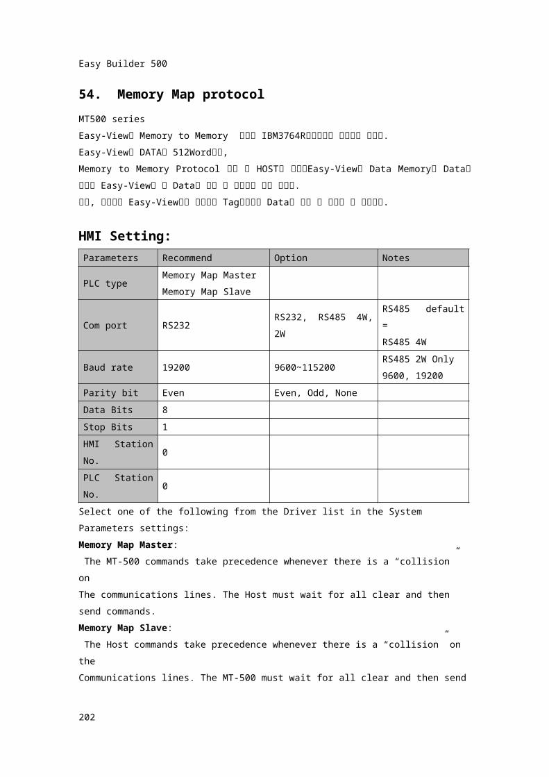
54. Memory Map protocolMT500 series Easy-View의 Memory to Memory 통신은 IBM3764R통신방식을 기준으로 합니다.Easy-View의 DATA는 512Word이며,Memory to Memory Protocol 사용 시 HOST와 접속된Easy-View는 Data Memory에 Data를 보내고 Easy-View는 그 Data를 작화 된 형식으로 표현 합니다.또한, 사용자는 Easy-View에서 제공되는 Tag형식으로 Data를 설정 및 변경할 수 있습니다.
HMI Setting:Parameters Recommend Option Notes
PLC typeMemory Map MasterMemory Map Slave
Com port RS232RS232, RS485 4W, 2W
RS485 default =RS485 4W
Baud rate 19200 9600~115200RS485 2W Only9600, 19200
Parity bit Even Even, Odd, NoneData Bits 8Stop Bits 1HMI Station No.
0
PLC Station No.
0
Select one of the following from the Driver list in the System Parameters settings:Memory Map Master: The MT-500 commands take precedence whenever there is a “collision” onThe communications lines. The Host must wait for all clear and then send commands.Memory Map Slave: The Host commands take precedence whenever there is a “collision” on theCommunications lines. The MT-500 must wait for all clear and then send commands.
205
Easy Builder 500
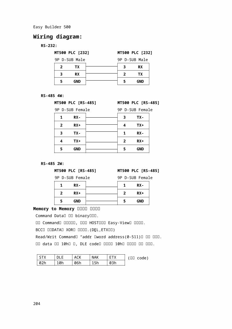
Wiring diagram:RS-232:
MT500 PLC [232] MT500 PLC [232]9P D-SUB Male 9P D-SUB Male
2 TX 3 RX3 RX 2 TX5 GND 5 GND
RS-485 4W:MT500 PLC [RS-485] MT500 PLC [RS-485]9P D-SUB Female 9P D-SUB Female
1 RX- 3 TX-
2 RX+ 4 TX+
3 TX- 1 RX-
4 TX+ 2 RX+
5 GND 5 GND
RS-485 2W:MT500 PLC [RS-485] MT500 PLC [RS-485]9P D-SUB Female 9P D-SUB Female
1 RX- 1 RX-
2 RX+ 2 RX+
5 GND 5 GNDMemory to Memory 통신상의 제어방식
Command Data는 모두 binary입니다. 모든 Command는 양방향이며, 그것은 HOST로부터 Easy-View로 보냅니다. BCC의 전송DATA는 XOR로 취합니다.(DEL,ETX포함) Read/Writ Command의 “addr”는word address(0-511)로 지정 됩니다. 전송 data 값이 10h일 때, DLE code와 같으므로 10h를 중복전송 해야 합니다.
(통신 code)
206
STX DLE ACK NAK ETX02h 10h 06h 15h 03h
Easy Builder 500
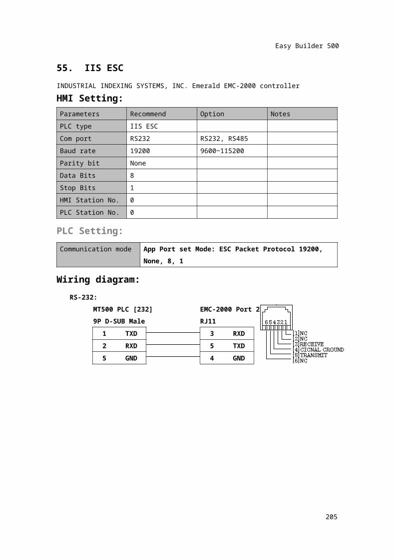
55. IIS ESCINDUSTRIAL INDEXING SYSTEMS, INC. Emerald EMC-2000 controllerHMI Setting:Parameters Recommend Option NotesPLC type IIS ESCCom port RS232 RS232, RS485Baud rate 19200 9600~115200Parity bit NoneData Bits 8Stop Bits 1HMI Station No. 0PLC Station No. 0
PLC Setting:Communication mode App Port set Mode: ESC Packet Protocol 19200,
None, 8, 1
Wiring diagram:RS-232:
MT500 PLC [232] EMC-2000 Port 29P D-SUB Male RJ11
1 TXD 3 RXD2 RXD 5 TXD5 GND 4 GND
207
Easy Builder 500
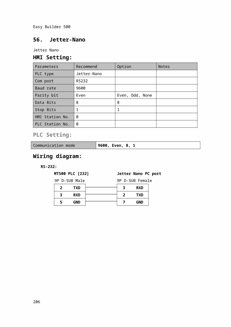
56. Jetter-NanoJetter NanoHMI Setting:Parameters Recommend Option NotesPLC type Jetter-NanoCom port RS232Baud rate 9600Parity bit Even Even, Odd, NoneData Bits 8 8Stop Bits 1 1HMI Station No. 0PLC Station No. 0
PLC Setting:Communication mode 9600, Even, 8, 1
Wiring diagram:RS-232:
MT500 PLC [232] Jetter Nano PC port9P D-SUB Male 9P D-SUB Female
2 TXD 3 RXD3 RXD 2 TXD5 GND 7 GND
208
Easy Builder 500
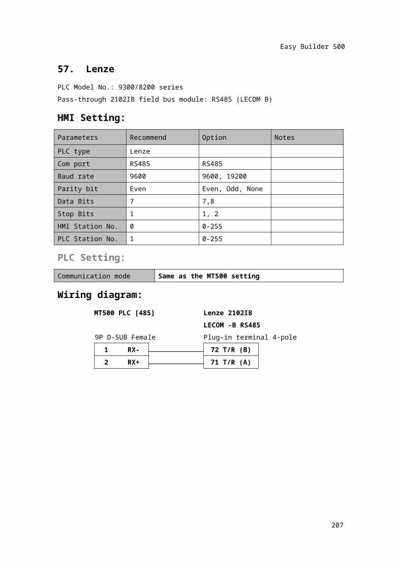
57. LenzePLC Model No.: 9300/8200 seriesPass-through 2102IB field bus module: RS485 (LECOM B)HMI Setting:Parameters Recommend Option NotesPLC type LenzeCom port RS485 RS485Baud rate 9600 9600, 19200Parity bit Even Even, Odd, NoneData Bits 7 7,8Stop Bits 1 1, 2HMI Station No. 0 0-255PLC Station No. 1 0-255PLC Setting:Communication mode Same as the MT500 setting
Wiring diagram:MT500 PLC [485] Lenze 2102IB
LECOM -B RS4859P D-SUB Female Plug-in terminal 4-pole
1 RX- 72 T/R (B)
2 RX+ 71 T/R (A)
209
8Pin miniDinFemale
Easy Builder 500
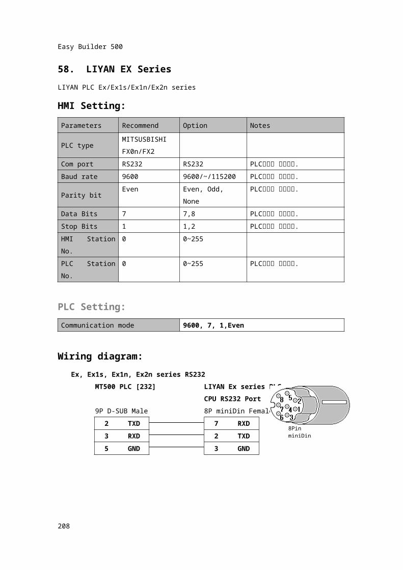
58. LIYAN EX SeriesLIYAN PLC Ex/Ex1s/Ex1n/Ex2n seriesHMI Setting:Parameters Recommend Option Notes
PLC typeMITSUSBISHIFX0n/FX2
Com port RS232 RS232 PLC설정과 일치시킴.Baud rate 9600 9600/~/115200 PLC설정과 일치시킴.Parity bit Even Even, Odd, None PLC설정과 일치시킴.Data Bits 7 7,8 PLC설정과 일치시킴.Stop Bits 1 1,2 PLC설정과 일치시킴.HMI Station No. 0 0~255PLC Station No. 0 0~255 PLC설정과 일치시킴.
PLC Setting:Communication mode 9600, 7, 1,Even
Wiring diagram:Ex, Ex1s, Ex1n, Ex2n series RS232
MT500 PLC [232] LIYAN Ex series PLCCPU RS232 Port
9P D-SUB Male 8P miniDin Female2 TXD 7 RXD3 RXD 2 TXD5 GND 3 GND
210
Easy Builder 500
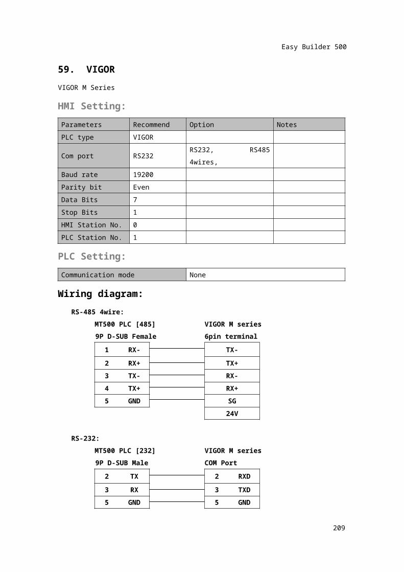
59. VIGORVIGOR M SeriesHMI Setting:Parameters Recommend Option NotesPLC type VIGORCom port RS232 RS232, RS485 4wires,Baud rate 19200Parity bit EvenData Bits 7Stop Bits 1HMI Station No. 0PLC Station No. 1
PLC Setting:Communication mode None
Wiring diagram:RS-485 4wire:
MT500 PLC [485] VIGOR M series9P D-SUB Female 6pin terminal
1 RX- TX-2 RX+ TX+3 TX- RX-4 TX+ RX+5 GND SG
24V
RS-232:MT500 PLC [232] VIGOR M series9P D-SUB Male COM Port
2 TX 2 RXD
3 RX 3 TXD5 GND 5 GND
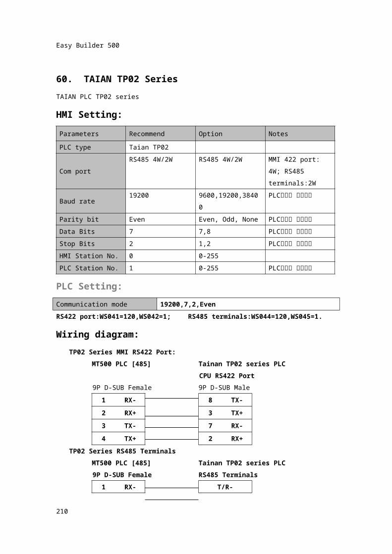
60. TAIAN TP02 SeriesTAIAN PLC TP02 seriesHMI Setting:
211
Easy Builder 500
Parameters Recommend Option NotesPLC type Taian TP02
Com portRS485 4W/2W RS485 4W/2W MMI 422 port: 4W;
RS485 terminals:2W
Baud rate 19200 9600,19200,38400 PLC설정과 일치시킴
Parity bit Even Even, Odd, None PLC설정과 일치시킴
Data Bits 7 7,8 PLC설정과 일치시킴
Stop Bits 2 1,2 PLC설정과 일치시킴
HMI Station No. 0 0-255PLC Station No. 1 0-255 PLC설정과 일치시킴
PLC Setting:Communication mode 19200,7,2,EvenRS422 port:WS041=120,WS042=1; RS485 terminals:WS044=120,WS045=1.Wiring diagram:
TP02 Series MMI RS422 Port: MT500 PLC [485] Tainan TP02 series PLC
CPU RS422 Port9P D-SUB Female 9P D-SUB Male
1 RX- 8 TX-2 RX+ 3 TX+3 TX- 7 RX-4 TX+ 2 RX+
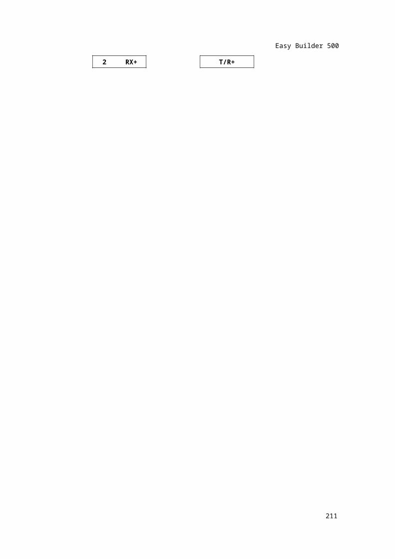
TP02 Series RS485 TerminalsMT500 PLC [485] Tainan TP02 series PLC9P D-SUB Female RS485 Terminals
1 RX- T/R-2 RX+ T/R+
212
Easy Builder 500
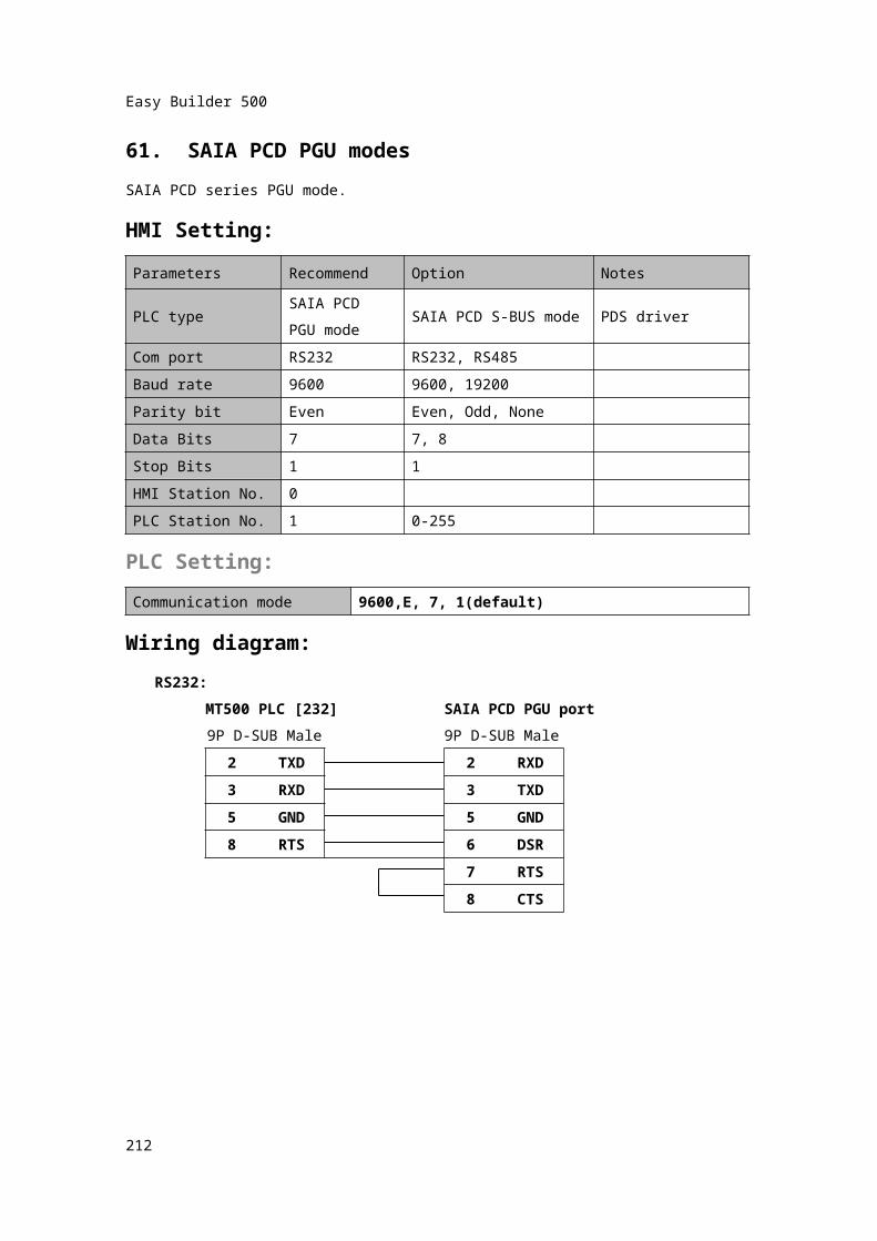
61. SAIA PCD PGU modesSAIA PCD series PGU mode.HMI Setting:Parameters Recommend Option Notes
PLC typeSAIA PCD PGU mode
SAIA PCD S-BUS mode PDS driver
Com port RS232 RS232, RS485Baud rate 9600 9600, 19200Parity bit Even Even, Odd, NoneData Bits 7 7, 8Stop Bits 1 1HMI Station No. 0PLC Station No. 1 0-255
PLC Setting:Communication mode 9600,E, 7, 1(default)
Wiring diagram:RS232:
MT500 PLC [232] SAIA PCD PGU port9P D-SUB Male 9P D-SUB Male
2 TXD 2 RXD3 RXD 3 TXD5 GND 5 GND
8 RTS 6 DSR
7 RTS8 CTS
213
Easy Builder 500
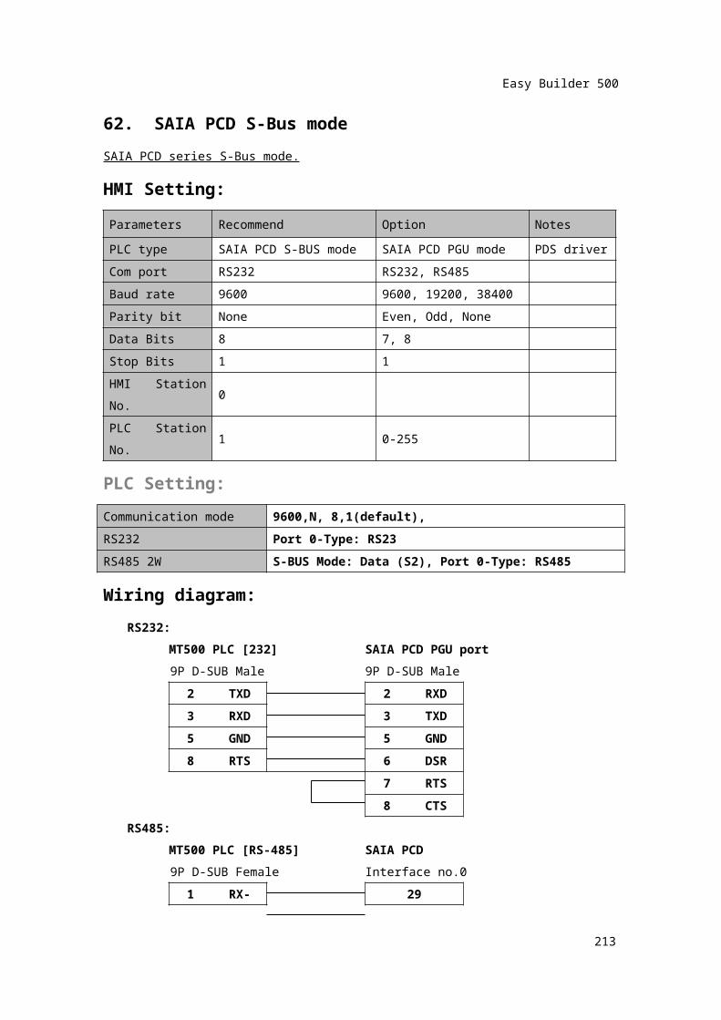
62. SAIA PCD S-Bus modeSAIA PCD series S-Bus mode.HMI Setting:Parameters Recommend Option NotesPLC type SAIA PCD S-BUS mode SAIA PCD PGU mode PDS driverCom port RS232 RS232, RS485Baud rate 9600 9600, 19200, 38400Parity bit None Even, Odd, NoneData Bits 8 7, 8Stop Bits 1 1HMI Station No. 0PLC Station No. 1 0-255
PLC Setting:Communication mode 9600,N, 8,1(default),RS232 Port 0-Type: RS23RS485 2W S-BUS Mode: Data (S2), Port 0-Type: RS485
Wiring diagram:RS232:
MT500 PLC [232] SAIA PCD PGU port9P D-SUB Male 9P D-SUB Male
2 TXD 2 RXD3 RXD 3 TXD5 GND 5 GND
8 RTS 6 DSR
7 RTS8 CTS
RS485:MT500 PLC [RS-485] SAIA PCD9P D-SUB Female Interface no.0
1 RX- 292 RX+ 28
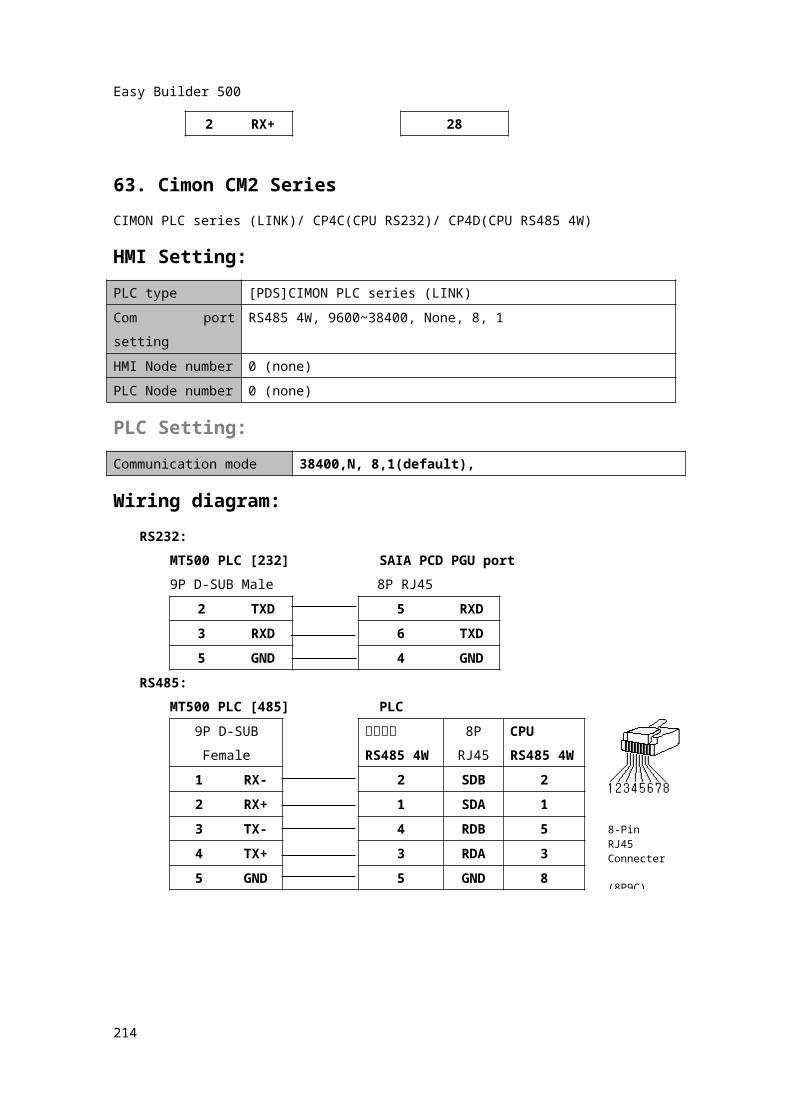
63. Cimon CM2 SeriesCIMON PLC series (LINK)/ CP4C(CPU RS232)/ CP4D(CPU RS485 4W)
214
Easy Builder 500
HMI Setting:PLC type [PDS]CIMON PLC series (LINK)Com port setting RS485 4W, 9600~38400, None, 8, 1HMI Node number 0 (none)PLC Node number 0 (none)PLC Setting:Communication mode 38400,N, 8,1(default),
Wiring diagram:RS232:
MT500 PLC [232] SAIA PCD PGU port9P D-SUB Male 8P RJ45
2TXD
5 RXD
3 RXD 6 TXD5 GND 4 GND
RS485:MT500 PLC [485] PLC
9P D-SUBFemale
통신카드
RS485 4W
8PRJ45
CPURS485 4W
1 RX- 2 SDB 2
2 RX+ 1 SDA 13 TX- 4 RDB 5
4 TX+ 3 RDA 35 GND 5 GND 8
215
8-Pin RJ45Connecter (8P9C)

Easy Builder 500
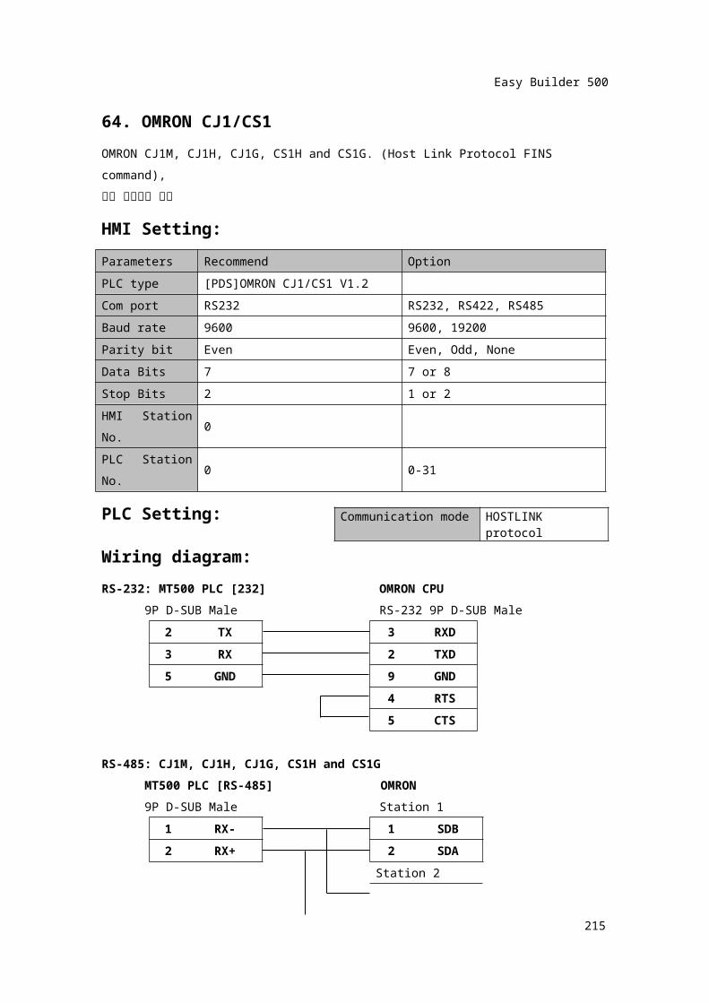
64. OMRON CJ1/CS1OMRON CJ1M, CJ1H, CJ1G, CS1H and CS1G. (Host Link Protocol FINS command),확장 어드레스 모드
HMI Setting:Parameters Recommend OptionPLC type [PDS]OMRON CJ1/CS1 V1.2Com port RS232 RS232, RS422, RS485
Baud rate 9600 9600, 19200
Parity bit Even Even, Odd, None
Data Bits 7 7 or 8
Stop Bits 2 1 or 2
HMI Station No.
0
PLC Station No.
0 0-31
PLC Setting:Wiring diagram:RS-232: MT500 PLC [232] OMRON CPU
9P D-SUB Male RS-232 9P D-SUB Male2 TX 3 RXD3 RX 2 TXD5 GND 9 GND
4 RTS5 CTS
RS-485: CJ1M, CJ1H, CJ1G, CS1H and CS1GMT500 PLC [RS-485] OMRON9P D-SUB Male Station 1
1 RX- 1 SDB
2 RX+ 2 SDA
Station 21 SDB
216
Communication mode HOSTLINK protocol
Easy Builder 500
2 SDA
217
Easy Builder 500
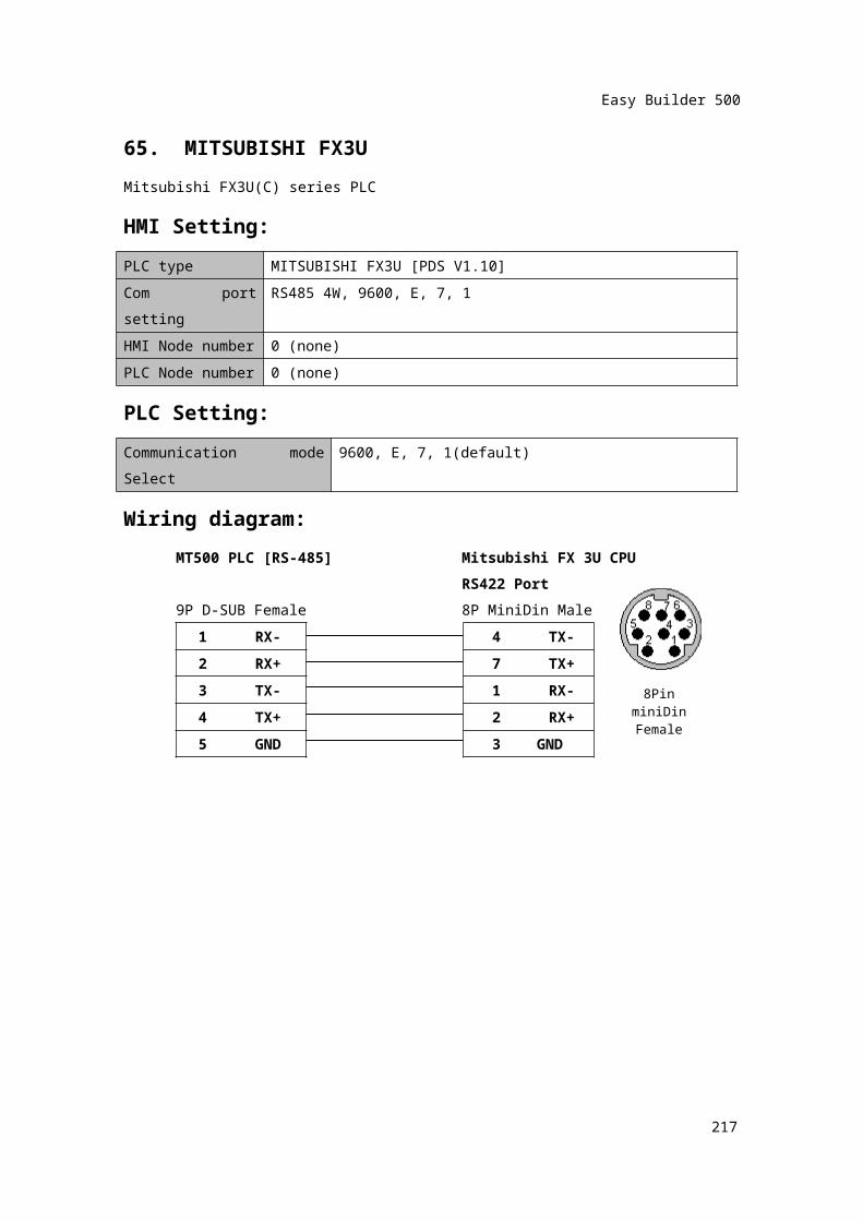
65. MITSUBISHI FX3UMitsubishi FX3U(C) series PLCHMI Setting:PLC type MITSUBISHI FX3U [PDS V1.10]Com port setting RS485 4W, 9600, E, 7, 1HMI Node number 0 (none)PLC Node number 0 (none)PLC Setting:Communication mode Select
9600, E, 7, 1(default)
Wiring diagram:MT500 PLC [RS-485] Mitsubishi FX 3U CPU
RS422 Port9P D-SUB Female 8P MiniDin Male
1 RX- 4 TX-
2 RX+ 7 TX+3 TX- 1 RX-
4 TX+ 2 RX+5 GND 3 GND
218
8Pin miniDinFemale
Easy Builder 500
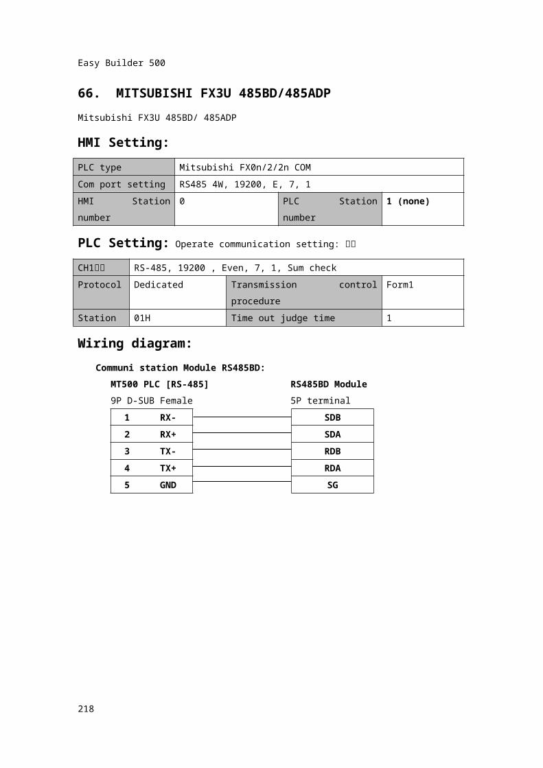
66. MITSUBISHI FX3U 485BD/485ADPMitsubishi FX3U 485BD/ 485ADPHMI Setting:PLC type Mitsubishi FX0n/2/2n COMCom port setting RS485 4W, 19200, E, 7, 1HMI Station number 0 PLC Station number 1 (none)
PLC Setting: Operate communication setting: 체크
CH1설정 RS-485, 19200 , Even, 7, 1, Sum checkProtocol Dedicated Transmission control procedure Form1Station 01H Time out judge time 1Wiring diagram:
Communi station Module RS485BD:MT500 PLC [RS-485] RS485BD Module9P D-SUB Female 5P terminal
1 RX- SDB
2 RX+ SDA3 TX- RDB4 TX+ RDA5 GND SG
219
Easy Builder 500
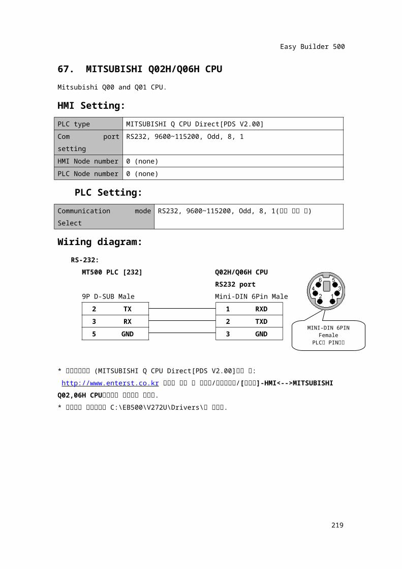
67. MITSUBISHI Q02H/Q06H CPU Mitsubishi Q00 and Q01 CPU.HMI Setting:PLC type MITSUBISHI Q CPU Direct[PDS V2.00]Com port setting RS232, 9600~115200, Odd, 8, 1HMI Node number 0 (none)PLC Node number 0 (none) PLC Setting:Communication mode Select
RS232, 9600~115200, Odd, 8, 1(기본 설정 값)
Wiring diagram:RS-232:
MT500 PLC [232] Q02H/Q06H CPURS232 port
9P D-SUB Male Mini-DIN 6Pin Male
2 TX 1 RXD
3 RX 2TXD
5 GND 3 GND
* 통신드라이버 (MITSUBISHI Q CPU Direct[PDS V2.00]받는 곳: http://www.enterst.co.kr 사이트 접속 후 자료실/소프트웨어/[이지뷰]-HMI<-->MITSUBISHI Q02,06H CPU직결통신 프로토콜 선택함.* 다운받은 압축파일을 C:\EB500\V272U\Drivers\에 풀어줌.
220
MINI-DIN 6PIN Female
PLC측 PIN번호
Easy Builder 500
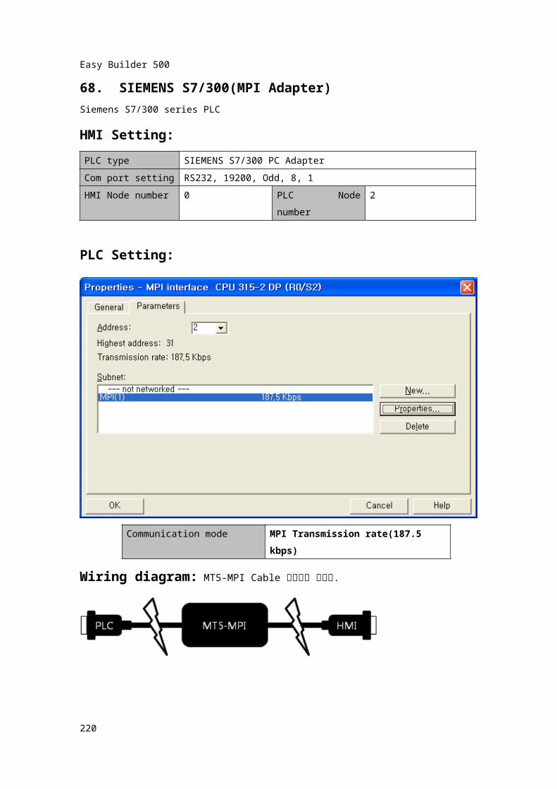
68. SIEMENS S7/300(MPI Adapter)Siemens S7/300 series PLCHMI Setting:PLC type SIEMENS S7/300 PC AdapterCom port setting RS232, 19200, Odd, 8, 1HMI Node number 0 PLC Node
number2
PLC Setting:
Communication mode MPI Transmission rate(187.5 kbps)
Wiring diagram: MT5-MPI Cable 사용하여 통신함.
221
Easy Builder 500
제 7 장 MT 의 Local Data 영역 Local Bit(LB), Local Word(LW), Recipe Word(RW) 등은 다음과 같은 기능 이외로는 사용할
수 없습니다.Local Bits : 9000~9999, Local Words : 9000~9999, Recipe Words : 60000~655351 Local Bit (LB)
LB0000 ~ LB8999 ( User용) LB9000 ~ (시스템 내부용)위 치 설 명 비 고9000 ~9009
상시 ON Numeric Input의 Trigger Bit로 활용
(읽기/쓰기)
9010 Recipe Memory에download 표시
Recipe Memory에 download중 ON,Download 완료 후 OFF (읽기)
9011 Recipe Memory에
Upload 표시
Recipe Memory에 Upload 중 ON,Upload 완료 후 OFF (읽기)
9012Recipe Memory에 Upload,Download할 때 표시
Recipe Memory에 전송 MT로 download전송 때 ON, 설정 완성될 때 OFF (읽기)
9013 Touch indicator화면에Touch할 때 ON됨
-> (읽기)
9014 CPU indicatorCPU 사용 시 ON
(읽기)
9015 Alarm indicator화면에 Alarm 발생시 ON (읽기)
-> 9016 Printer Error Indicate 프린터 이상시 ON, 정상일때 OFF (읽기)
9017 Printer ControlON일 때, 프린터 사용 불가, OFF일 때 프린터사용 가능 System Parameter에서 Printer설정 후 사용가능 (읽기/쓰기)
9020 Pen Message Board사용 시 Pan 설정 ON(읽기/쓰기)
9021 Brush Message Board사용 시 Brush 설정 ON(읽기/쓰기)
9022 Clipping Message Board 사용 시 Clipping 설정 ON(읽기/쓰기)
9030 Pen width Pixel 1 Message Board 사용 시 Pen의 굵기 선택
(1 Pixel ; 1화소) (읽기/쓰기)위 치 설 명 비 고
222
Easy Builder 500
9031 Pen width Pixel 2 Message Board사용 시 Pen의 굵기 선택(2 Pixel; 2화소) (읽기/쓰기)
9032 Pen width Pixel 3 Message Board 사용 시 Pen의 굵기 선택(3 Pixel ; 3화소) (읽기/쓰기)
9040 Fast select screen Icon(숨김/표시)
ON일 때 화면(Window)을 숨김 OFF 일 때,화면(Window)이 표시됨. (읽기/쓰기)
9041 Task Bar(숨김/표시)
ON일 때, Task Bar를 숨김, OFF 일 때,Task Bar가 표시됨 (읽기/쓰기)
9042 Task Button (숨김/표시)
ON일 때, Task Button을 숨김 OFF 일 때,Task Button이 표시됨 (읽기/쓰기)
9043Fast select ScreenTask Bar Task Button(숨김/표시)
ON일 때Fast select Screen/Task Bar/Task Button을 동시에 숨김. OFF일 때Fast select Screen/Task Bar/Task Button이 동시에 표시됨.(읽기/쓰기)
9044 System Parameters를Recipe 메모리에 저장기능
ON일 때, System Parameters 를 Recipe 메모리에 저장됨.이후 system 셋팅된후 현재 BIT가 OFF됨. (읽기/쓰기)
9045 MT 재시작. ON일 때, MT 재시작.재시작 후 BIT가 OFF됨. (쓰기)
9046 Low security level9050 도시바 T/C 쓰기 허용비트 ON일 때, 타이머/카운터 사용가능
9051 Back Light가 OFF일 때, Touch 기능 사용여부 설정
ON일 때 Back Light OFF중 화면의 Touch기능이
동작 안됨, OFF시 Back Light OFF중 화면의 Touch기능이 동작됨 (읽기/쓰기)
9052 MT의 현재 화면번호를
PLC로 재전송 허용 여부
PLC Control에서 화면(Window)을 전환할 때, 현재의 화면번호를 PLC로 전송 여부. ON일 때 사용
안 함 (Change Window편 참조)
9055 MT와 PLC통신 상태ON (통신 중)/OFF (통신 안됨)로 나타냄.(읽기/쓰기)
9056 MT와 PLC통신이 안될 때,Touch 기능의 여부.
ON일 때 Touch 안됨, OFF일 때 Touch 가능
(읽기/쓰기)
223
Easy Builder 500
9060~9061
Keypad Control Bit,Keypad를 화면 왼쪽에 호출시 사용
화면을 Touch하여, 숫자를 입력 하거나
ASCII입력할 때, 왼쪽 터치시 bit가 On. Keypad의 Enter, ESC Key에 의해 bit가
OFF됨. Direct Window로 활용 (읽기)9062 Keypad를 왼쪽 위에 호출시 사용 왼쪽 터치 시 ON (읽기)9063 Keypad를 왼쪽 아래에 호출시 사용 왼쪽 아래 터치 시, ON (읽기)9064~9065 Keypad를 오른쪽에 호출시 사용 오른쪽 터치 시, ON (읽기)
9066 Keypad를 오른쪽 위에 호출시 사용 오른쪽 위 터치 시, ON (읽기)9067 Keypad를 오른쪽아래에 호출시 사용 오른쪽 아래 터치 시, ON (읽기)9068~9069 Keypad를 전 영역에 호출 시 사용 전구역 터치 시, ON (읽기)
9080 Keypad를 중앙 위쪽에 호출시 사용. 중앙 위쪽 터치 시, ON (읽기)9081 Keypad를 중앙 아래에 호출시 사용. 중앙 아래 터치 시, ON (읽기)9090 Event log 삭제 Event log 삭제기능.ON후 자동 OFF됨.
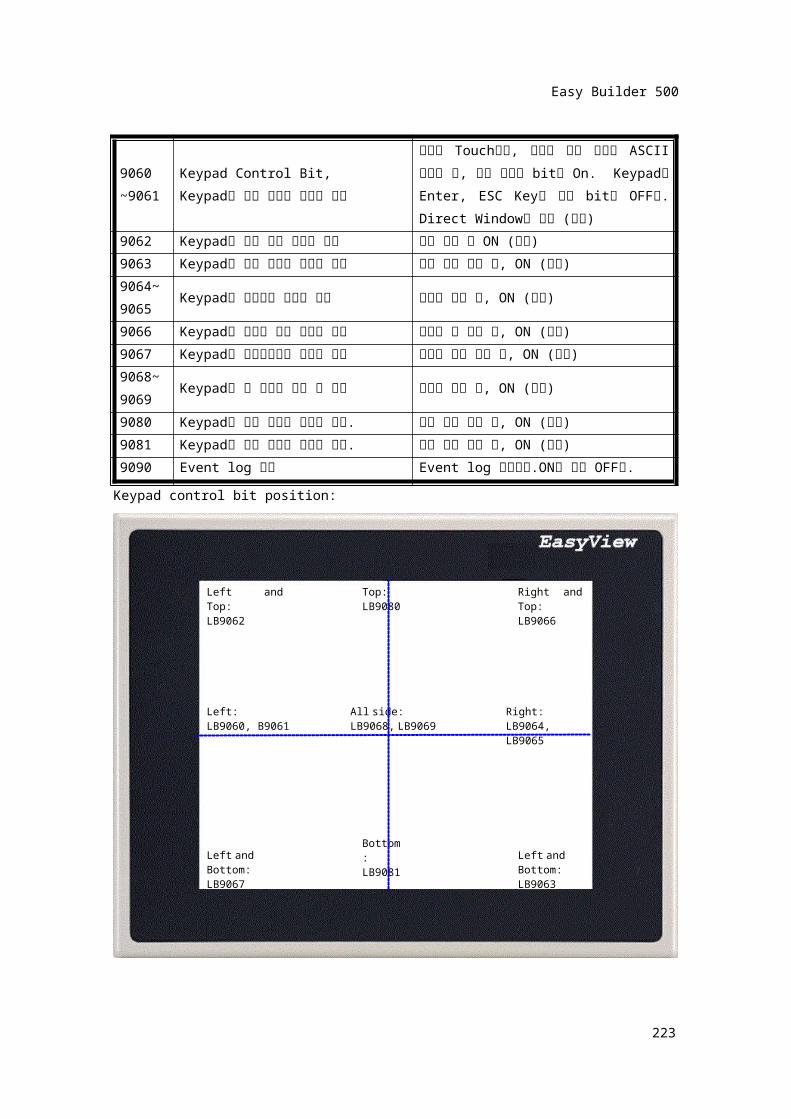
Keypad control bit position:
224
Left and Top:LB9062
Right and Top:LB9066
Left:LB9060, B9061
All side:LB9068, LB9069
Right:LB9064, LB9065
Left and Bottom:LB9063
Top:LB9080
Bottom:LB9081Left and Bottom:
LB9067
Easy Builder 500
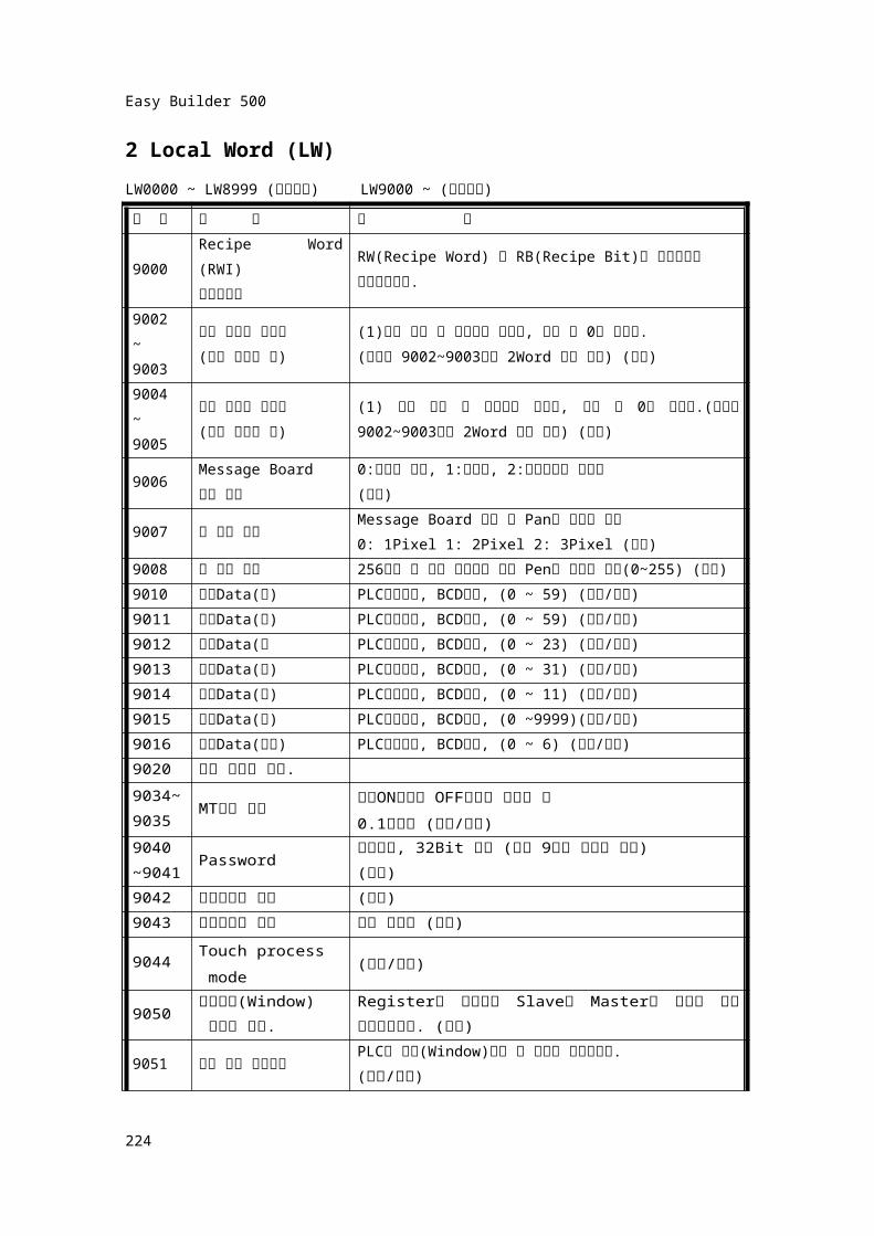
2 Local Word (LW)LW0000 ~ LW8999 (사용자용) LW9000 ~ (시스템용)위 치 설 명 비 고
9000 Recipe Word (RWI)인덱스표시
RW(Recipe Word) 와 RB(Recipe Bit)를 액세스하여
색인기능사용.9002 ~ 9003
수치 입력의 최대치
(수치 입력일 때)(1)수치 입력 시 최대치가 표시됨, 입력 후 0이 표시됨.(최대치 9002~9003까지 2Word 사용 가능) (읽기)
9004 ~ 9005
수치 입력의 최소치
(수치 입력일 때)(1) 수치 입력 시 최소치가 표시됨, 입력 후 0이 표시됨.(최대치 9002~9003까지 2Word 사용 가능) (읽기)
9006 Message Board도구 상태
0:펜으로 쓰기, 1:지우개, 2:드래그하여 지우기
(읽기)
9007 펜 굵기 표시Message Board 사용 시 Pan의 굵기를 표시
0: 1Pixel 1: 2Pixel 2: 3Pixel (읽기)
9008 펜 색상 표시256색상 중 현재 선택되어 있는 Pen의 색상을 표시
(0~255) (읽기)9010 시계Data(초) PLC시간변환, BCD양식, (0 ~ 59) (읽기/쓰기)9011 시계Data(분) PLC시간변환, BCD양식, (0 ~ 59) (읽기/쓰기)9012 시계Data(시 PLC시간변환, BCD양식, (0 ~ 23) (읽기/쓰기)9013 시계Data(일) PLC시간변환, BCD양식, (0 ~ 31) (읽기/쓰기)9014 시계Data(월) PLC시간변환, BCD양식, (0 ~ 11) (읽기/쓰기)9015 시계Data(년) PLC시간변환, BCD양식, (0 ~9999)(읽기/쓰기)9016 시계Data(요일) PLC시간변환, BCD양식, (0 ~ 6) (읽기/쓰기)9020 사용 아이템 개수.9034~ 9035
MT사용 시간 전원ON시부터 OFF시까지 카운터 됨
0.1초단위 (읽기/쓰기)9040 ~9041
Password 비밀번호, 32Bit 수치 (단지 9자리 숫자로 한정)(쓰기)
9042 비밀번호의 등급 (읽기)9043 보호등급을 설정 강제 설정함 (쓰기)
9044 Touch process mode
(읽기/쓰기)
9050 현재화면(Window) 번호를 표시.
Register를 이용하여 Slave와 Master의 화면을
서로 일치시킵니다. (읽기)
9051 전환 화면 번호표시PLC로 화면(Window)전환 된 결과를 표시합니다.(읽기/쓰기)
225
Easy Builder 500
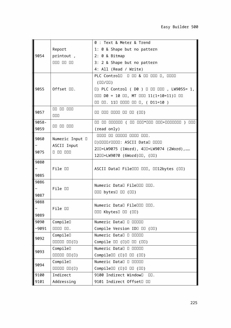
9054 Report printout ,프린터 양식 설정
0 : Text & Meter & Trend1: 0 & Shape but no pattern2: 0 & Bitmap 3: 2 & Shape but no pattern4: All (Read / Write)
9055 Offset 설정.
PLC Control의 창 전환 & 화면 프린트 시, 옵셋설정 (읽기/쓰기)예) PLC Control ( D0 ) 에 화면 전환시 , LW9055= 1,그리고 D0 = 10 이면, MT 화면을 11(1+10=11)번 화면
으로 전환. 11번 화면으로 전환 후, ( D11=10 )
9057 알람 이력 아이템
사이즈모든 아이템 사이즈의 작업 정보 (읽기)
9058-9059 알람 이력 사이즈
작업 정보 데이터베이스 ( 전체 아이템*아이템 사이즈+작업정보사이즈 ) 사이즈 (read only)
9060 ~ 9075
Numeric Input 과ASCII Input의 현재 입력치
수치입력 또는 문자입력의 입력치를 나타냄. 예)수치입력/문자입력: ASCII Data를 사용하여2자리=LW9075 (1Word), 4자리=LW9074 (2Word),……12자리=LW9070 (6Word)설정, (읽기)
9080 ~ 9085
File 이름 ASCII Data로 File이름을 나타냄, 모두12bytes (읽기)
9086 ~ 9087
File 용량Numeric Data로 File용량을 나타냄. 단위는 bytes로 표시 (읽기)
9088 ~ 9089
File 용량Numeric Data로 File용량을 나타냄. 단위는 Kbytes로 표시 (읽기)
9090 ~9091
Compile한프로그램 원본.
Numeric Data로 이 프로그램의Compile Version ID를 표시 (읽기)
9092 Compile한프로그램의 일시(년)
Numeric Data로 이 프로그램의Compile 일시 (년)를 표시 (읽기)
9093 Compile한프로그램의 일시(월)
Numeric Data로 이 프로그램의Compile일시 (월)를 표시 (읽기)
9094 Compile한프로그램의 일시(일)
Numeric Data로 이 프로그램의Compile일시 (일)를 표시 (읽기)
91009101
Indirect Addressing이며 PLC외부용으로사용
9100 Indirect Window를 지정.9101 Indirect Offset을 지정
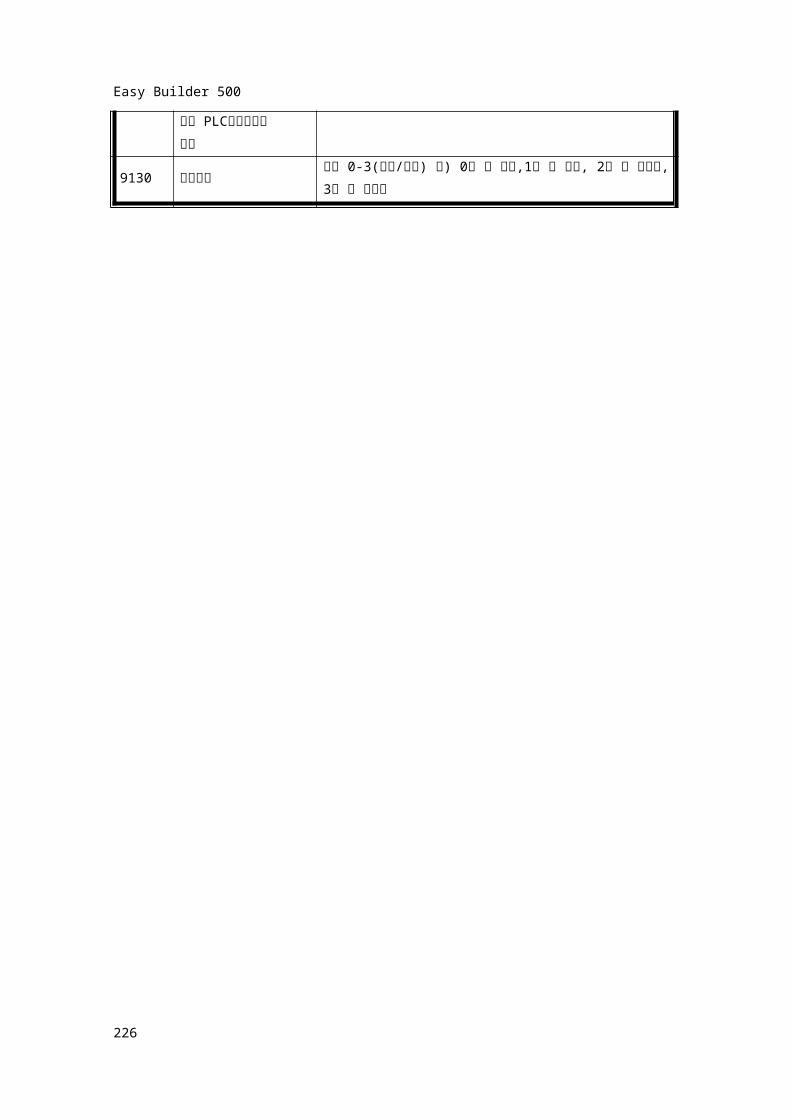
9130 언어변환언어 0-3(읽기/쓰기) 예) 0일 때 한글,1일 때 영어, 2일 때 중국어, 3일 때 일본어
226
Easy Builder 500
227
Easy Builder 500
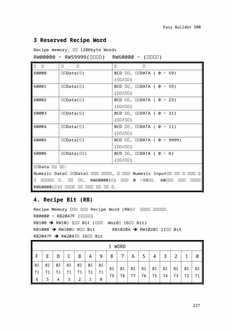
3 Reserved Recipe WordRecipe memory, 모두 128Kbyte WordsRW00000 ~ RW59999(사용자용) RW60000 ~ (시스템용)위 치 서 술 비 고60000 시계Data(초) BCD 양식, 내부DATA ( 0 ~ 59)
(읽기/쓰기)60001 시계Data(분) BCD 양식, 내부DATA ( 0 ~ 59)
(읽기/쓰기)60002 시계Data(시) BCD 양식, 내부DATA ( 0 ~ 23)
(읽기/쓰기)60003 시계Data(일) BCD 양식, 내부DATA ( 0 ~ 31)
(읽기/쓰기)60004 시계Data(월) BCD 양식, 내부DATA ( 0 ~ 11)
(읽기/쓰기)60005 시계Data(년) BCD 양식, 내부DATA ( 0 ~ 9999)
(읽기/쓰기)60006 시계Data(주기) BCD 양식, 내부DATA ( 0 ~ 6)
(읽기/쓰기)시계Data 주의 사항:Numeric Data로 시계Data의 시간이 나타나고, 그 수치를 Numeric Input으로 고칠
수 있으나 쓸 때 주의하여야 함. 예를 들어, RW60000(초) 범위는 0 ~59이다. 60이상의 수치를 설정하면 RW60000(초)는 계속하여 증가 되므로 주의 해야 함.
4. Recipe Bit (RB)Recipe Memory 앞에서 소개한 Recipe Word (RW)와 대응되어 사용합니다.RB0000 ~ RB2047F (사용자용)RB100 RW10의 1번째 Bit (하나의 Word는 16개의 Bit)RB1008 RW100의 9번째 Bit RB1020A RW1020의 11번째 Bit RB2047F RW2047의 16번째 Bit
1 WORDF E D C B A 9 8 7 6 5 4 3 2 1 0
BIT16
BIT15
BIT14
BIT13
BIT12
BIT11
BIT10
BIT9
BIT8
BIT7
BIT6
BIT5
BIT4
BIT3
BIT2
BIT1
228
Easy Builder 500
5.RWI. RBIRecipe MemoryLW9000과 함께 사용합니다.RWI0000 ~ RWI32767(사용자용)RBI0000 ~ RBI 2047F(사용자용)RWI RW가 Recipe Memory 의 Index RegisterRBI RB 가 Recipe Memory 의 Index RegisterRWI. RBI 는 LW9000과 함께 사용합니다.예 : ASCII DataRead address = RWI 200LW90000 = 50이라면 ASCII Data는 RW250의 수치가 나타납니다.LW90000 = 36이라면 ASCII Data는 RW236의 수치가 나타납니다.6. Ms_ RB. Ms_LB. Ms_RW. Ms_LW이상의 4가지로 MT가 여러 대로 Link(1:N) 통신 할 때 사용합니다.MT 여러 대를 Link(1:N) 통신 할 때, 효과적으로 Data를 전달 할 수 있습니다.예를 들어, 일반적인Trend Display 표현 시 Slave가 Master를 통하여, PLC의 Data를
읽어오기 때문에 속도가 느립니다.이때, Master가 Read한 PLC의 Data를 Ms_ RB. Ms_LB. Ms_RW. Ms_LW등으로 공유하면
보다 빠른 속도로 Data를 처리 할 수 있습니다.
Ms_ RB: Master 내부의 Register(RB) 를 Read합니다. 범위는 0000 ~ 4095입니다.Ms_ RB 100 Master 내부 LW10은 1 Bit를 Read합니다
Ms_ RB 1008 Master 내부 LW100은 9 Bit를 Read합니다
Ms_ RB 1000A Master 내부 LW1000은 11 Bit를 Read합니다
Ms_ RB 4090F Master 내부 LW4090은 16 Bit를 Read합니다
Ms_ LB: Master 내부의 Register(LB) 를 Read합니다. 범위는 0000 ~ 9999입니다.Ms_ LB 100 Master 내부 LB 100을 Read합니다
Ms_ LB 3200 Master 내부 LB 3200을 Read합니다
Ms_ RW: Master 내부의 Register(RW) 를 Read합니다. 범위는 0000 ~ 65535입니다.Ms_ RW 11100 Master 내부 RW 11100을 Read합니다
Ms_ RW 32001 Master 내부 RW 32001을 Read합니다
229

Easy Builder 500
Ms_LW: Master 내부의 Register(LW) 를 Read합니다. 범위는 0000 ~ 9999입니다.Ms_ LW 1100 Master 내부 LW 1100을 Read합니다
Ms_ LW 2001 Master 내부 LW2001을 Read합니다
PS : 일반적으로 MS-LW. Ms_LB. Ms_RW. Ms_LW의 4가지 Device는 Slave에서
사용합니다. 작화 할 때 4가지의 MT Device을 설정한 후, MT가 동작할 때 Slave는 자동적으로 MT내부의
Register를 Read합니다. 단 Master가 편집화면이라도 이 접점을 사용하면 Master가 작동할
때 자동적으로 MT내부에 대응하는 Register를 찾습니다.
230
Related Documents