xx MTM400A, IPM400A, and RFM300 DTV Monitors Specifications and Performance Verification ZZZ Technical Reference *P077017602* 077-0176-02

Welcome message from author
This document is posted to help you gain knowledge. Please leave a comment to let me know what you think about it! Share it to your friends and learn new things together.
Transcript

xx
MTM400A, IPM400A, and RFM300DTV MonitorsSpecifications and Performance Verification
ZZZ
Technical Reference
*P077017602*
077-0176-02


MTM400A, IPM400A, and RFM300DTV MonitorsSpecifications and Performance Verification
ZZZ
Technical Reference
xx
This document applies to firmware versions 4.0 and above.
www.tektronix.com077-0176-02

Copyright © Tektronix. All rights reserved. Licensed software products are owned by Tektronix or its subsidiariesor suppliers, and are protected by national copyright laws and international treaty provisions.
Tektronix products are covered by U.S. and foreign patents, issued and pending. Information in this publicationsupersedes that in all previously published material. Specifications and price change privileges reserved.
TEKTRONIX and TEK are registered trademarks of Tektronix, Inc.
FlexVuPlus is a registered trademarks of Tektronix, Inc.
Contacting Tektronix
Tektronix, Inc.14200 SW Karl Braun DriveP.O. Box 500Beaverton, OR 97077USA
For product information, sales, service, and technical support:In North America, call 1-800-833-9200.Worldwide, visit www.tektronix.com to find contacts in your area.

Table of Contents
General Safety Summary . . . . . . . . . . . . . . . . . . . . . . . . . . . . . . . . . . . . . . . . . . . . . . . . . . . . . . . . . . . . . . . . . . . . . . . . . . . . . . . . . . . . . . . . . ivPreface .. . . . . . . . . . . . . . . . . . . . . . . . . . . . . . . . . . . . . . . . . . . . . . . . . . . . . . . . . . . . . . . . . . . . . . . . . . . . . . . . . . . . . . . . . . . . . . . . . . . . . . . . . . . . vii
Product Documentation .. . . . . . . . . . . . . . . . . . . . . . . . . . . . . . . . . . . . . . . . . . . . . . . . . . . . . . . . . . . . . . . . . . . . . . . . . . . . . . . . . . . . viiSpecifications . . . . . . . . . . . . . . . . . . . . . . . . . . . . . . . . . . . . . . . . . . . . . . . . . . . . . . . . . . . . . . . . . . . . . . . . . . . . . . . . . . . . . . . . . . . . . . . . . . . . . . . 1
Electrical, Hardware, and Signal Specifications. . . . . . . . . . . . . . . . . . . . . . . . . . . . . . . . . . . . . . . . . . . . . . . . . . . . . . . . . . . . 1Power Source Characteristics. . . . . . . . . . . . . . . . . . . . . . . . . . . . . . . . . . . . . . . . . . . . . . . . . . . . . . . . . . . . . . . . . . . . . . . . . . . . . . . . 15Environmental Characteristics . . . . . . . . . . . . . . . . . . . . . . . . . . . . . . . . . . . . . . . . . . . . . . . . . . . . . . . . . . . . . . . . . . . . . . . . . . . . . . 16Mechanical (Physical) Characteristics. . . . . . . . . . . . . . . . . . . . . . . . . . . . . . . . . . . . . . . . . . . . . . . . . . . . . . . . . . . . . . . . . . . . . . 16
Performance Verification . . . . . . . . . . . . . . . . . . . . . . . . . . . . . . . . . . . . . . . . . . . . . . . . . . . . . . . . . . . . . . . . . . . . . . . . . . . . . . . . . . . . . . . . . 17Requirements. . . . . . . . . . . . . . . . . . . . . . . . . . . . . . . . . . . . . . . . . . . . . . . . . . . . . . . . . . . . . . . . . . . . . . . . . . . . . . . . . . . . . . . . . . . . . . . . . . 17Procedure . . . . . . . . . . . . . . . . . . . . . . . . . . . . . . . . . . . . . . . . . . . . . . . . . . . . . . . . . . . . . . . . . . . . . . . . . . . . . . . . . . . . . . . . . . . . . . . . . . . . . . 17
MTM400A, IPM400A, and RFM300 Specifications and Performance Verification i
Table of Contents
List of Figures
Figure 1: DTV monitor RUI display .. . . . . . . . . . . . . . . . . . . . . . . . . . . . . . . . . . . . . . . . . . . . . . . . . . . . . . . . . . . . . . . . . . . . . . . . . . . 18
ii MTM400A, IPM400A, and RFM300 Specifications and Performance Verification

Table of Contents
List of Tables
Table i: Product documentation.. . . . . . . . . . . . . . . . . . . . . . . . . . . . . . . . . . . . . . . . . . . . . . . . . . . . . . . . . . . . . . . . . . . . . . . . . . . . . . . . viiTable 1: Remote User Interface (RUI) platform characteristics. . . . . . . . . . . . . . . . . . . . . . . . . . . . . . . . . . . . . . . . . . . . . . . 1Table 2: TS processor card - system timing clock . . . . . . . . . . . . . . . . . . . . . . . . . . . . . . . . . . . . . . . . . . . . . . . . . . . . . . . . . . . . . . 1Table 3: TS processor card - ASI interface . . . . . . . . . . . . . . . . . . . . . . . . . . . . . . . . . . . . . . . . . . . . . . . . . . . . . . . . . . . . . . . . . . . . . . 1Table 4: TS processor card - SMPTE310M interface . . . . . . . . . . . . . . . . . . . . . . . . . . . . . . . . . . . . . . . . . . . . . . . . . . . . . . . . . . 2Table 5: TS processor card - alarm connector . . . . . . . . . . . . . . . . . . . . . . . . . . . . . . . . . . . . . . . . . . . . . . . . . . . . . . . . . . . . . . . . . . . 3Table 6: TS processor card - alarms . . . . . . . . . . . . . . . . . . . . . . . . . . . . . . . . . . . . . . . . . . . . . . . . . . . . . . . . . . . . . . . . . . . . . . . . . . . . . . 4Table 7: TS processor card - LTC connector . . . . . . . . . . . . . . . . . . . . . . . . . . . . . . . . . . . . . . . . . . . . . . . . . . . . . . . . . . . . . . . . . . . . 4Table 8: TS processor card - Ethernet RJ-45 connector . . . . . . . . . . . . . . . . . . . . . . . . . . . . . . . . . . . . . . . . . . . . . . . . . . . . . . . . 4Table 9: QAM Annex A interface card characteristics . . . . . . . . . . . . . . . . . . . . . . . . . . . . . . . . . . . . . . . . . . . . . . . . . . . . . . . . . 5Table 10: QAM Annex B2 interface card characteristics . . . . . . . . . . . . . . . . . . . . . . . . . . . . . . . . . . . . . . . . . . . . . . . . . . . . . . 5Table 11: QAM Annex B2 measurements . . . . . . . . . . . . . . . . . . . . . . . . . . . . . . . . . . . . . . . . . . . . . . . . . . . . . . . . . . . . . . . . . . . . . . . 5Table 12: QAM Annex C interface card characteristics. . . . . . . . . . . . . . . . . . . . . . . . . . . . . . . . . . . . . . . . . . . . . . . . . . . . . . . . 6Table 13: 8PSK/QPSK interface card characteristics with 8PSK input . . . . . . . . . . . . . . . . . . . . . . . . . . . . . . . . . . . . . . 6Table 14: 8PSK/QPSK interface card characteristics with QPSK input. . . . . . . . . . . . . . . . . . . . . . . . . . . . . . . . . . . . . . 7Table 15: 8PSK and QPSK measurements . . . . . . . . . . . . . . . . . . . . . . . . . . . . . . . . . . . . . . . . . . . . . . . . . . . . . . . . . . . . . . . . . . . . . . 7Table 16: DVB-S2 interface card characteristics . . . . . . . . . . . . . . . . . . . . . . . . . . . . . . . . . . . . . . . . . . . . . . . . . . . . . . . . . . . . . . . 8Table 17: DVB-S2 measurements . . . . . . . . . . . . . . . . . . . . . . . . . . . . . . . . . . . . . . . . . . . . . . . . . . . . . . . . . . . . . . . . . . . . . . . . . . . . . . . . 8Table 18: 8VSB interface card characteristics . . . . . . . . . . . . . . . . . . . . . . . . . . . . . . . . . . . . . . . . . . . . . . . . . . . . . . . . . . . . . . . . . . 9Table 19: 8VSB measurements . . . . . . . . . . . . . . . . . . . . . . . . . . . . . . . . . . . . . . . . . . . . . . . . . . . . . . . . . . . . . . . . . . . . . . . . . . . . . . . . . . . 9Table 20: COFDM interface card characteristics . . . . . . . . . . . . . . . . . . . . . . . . . . . . . . . . . . . . . . . . . . . . . . . . . . . . . . . . . . . . . . 11Table 21: COFDM measurements . . . . . . . . . . . . . . . . . . . . . . . . . . . . . . . . . . . . . . . . . . . . . . . . . . . . . . . . . . . . . . . . . . . . . . . . . . . . . . . 11Table 22: GigE interface card - general characteristics . . . . . . . . . . . . . . . . . . . . . . . . . . . . . . . . . . . . . . . . . . . . . . . . . . . . . . . 13Table 23: GigE interface card - Ethernet electrical port. . . . . . . . . . . . . . . . . . . . . . . . . . . . . . . . . . . . . . . . . . . . . . . . . . . . . . . 13Table 24: GigE interface card - Ethernet Optical port. . . . . . . . . . . . . . . . . . . . . . . . . . . . . . . . . . . . . . . . . . . . . . . . . . . . . . . . . 13Table 25: GigE interface card - ASI input . . . . . . . . . . . . . . . . . . . . . . . . . . . . . . . . . . . . . . . . . . . . . . . . . . . . . . . . . . . . . . . . . . . . . . 14Table 26: GigE interface card - ASI output (active loopthrough of ASI/SMPTE input or TS from GigE
interface card) . . . . . . . . . . . . . . . . . . . . . . . . . . . . . . . . . . . . . . . . . . . . . . . . . . . . . . . . . . . . . . . . . . . . . . . . . . . . . . . . . . . . . . . . . . . . . . . . . 14Table 27: GigE interface card - SMPTE310M input (loopthrough to ASI output). . . . . . . . . . . . . . . . . . . . . . . . . 15Table 28: AC power source characteristics . . . . . . . . . . . . . . . . . . . . . . . . . . . . . . . . . . . . . . . . . . . . . . . . . . . . . . . . . . . . . . . . . . . . . 15Table 29: Transport stream card batteries. . . . . . . . . . . . . . . . . . . . . . . . . . . . . . . . . . . . . . . . . . . . . . . . . . . . . . . . . . . . . . . . . . . . . . . 15Table 30: Environmental characteristics . . . . . . . . . . . . . . . . . . . . . . . . . . . . . . . . . . . . . . . . . . . . . . . . . . . . . . . . . . . . . . . . . . . . . . . . 16Table 31: Mechanical characteristics. . . . . . . . . . . . . . . . . . . . . . . . . . . . . . . . . . . . . . . . . . . . . . . . . . . . . . . . . . . . . . . . . . . . . . . . . . . . 16
MTM400A, IPM400A, and RFM300 Specifications and Performance Verification iii

General Safety Summary
General Safety SummaryReview the following safety precautions to avoid injury and prevent damage tothis product or any products connected to it.
To avoid potential hazards, use this product only as specified.
Only qualified personnel should perform service procedures.
To Avoid Fire or PersonalInjury
Use Proper Power Cord. Use only the power cord specified for this product andcertified for the country of use.
Ground the Product. This product is grounded through the grounding conductorof the power cord. To avoid electric shock, the grounding conductor must beconnected to earth ground. Before making connections to the input or outputterminals of the product, ensure that the product is properly grounded.
Observe All Terminal Ratings. To avoid fire or shock hazard, observe all ratingsand markings on the product. Consult the product manual for further ratingsinformation before making connections to the product.
The inputs are not rated for connection to mains or Category II, III, or IV circuits.
Power Disconnect. The power cord disconnects the product from the power source.Do not block the power cord; it must remain accessible to the user at all times.
Do Not Operate Without Covers. Do not operate this product with covers or panelsremoved.
Do Not Operate With Suspected Failures. If you suspect that there is damage to thisproduct, have it inspected by qualified service personnel.
Avoid Exposed Circuitry. Do not touch exposed connections and componentswhen power is present.
Use Proper Fuse. Use only the fuse type and rating specified for this product.
Do Not Operate in Wet/Damp Conditions.
Do Not Operate in an Explosive Atmosphere.
Keep Product Surfaces Clean and Dry.
Provide Proper Ventilation. Refer to the manual’s installation instructions fordetails on installing the product so it has proper ventilation.
iv MTM400A, IPM400A, and RFM300 Specifications and Performance Verification

General Safety Summary
Terms in this Manual These terms may appear in this manual:
WARNING. Warning statements identify conditions or practices that could resultin injury or loss of life.
CAUTION. Caution statements identify conditions or practices that could result indamage to this product or other property.
Symbols and Terms on theProduct
These terms may appear on the product:
DANGER indicates an injury hazard immediately accessible as you readthe marking.
WARNING indicates an injury hazard not immediately accessible as youread the marking.
CAUTION indicates a hazard to property including the product.
The following symbol(s) may appear on the product:
MTM400A, IPM400A, and RFM300 Specifications and Performance Verification v

General Safety Summary
vi MTM400A, IPM400A, and RFM300 Specifications and Performance Verification

PrefaceThis manual contains the following information about the MTM400A, IPM400A,and RFM300 DTV Monitors:
Specifications lists the electrical, physical, and environmental specificationsof the DTV monitors.
Performance Verification contains a procedure to verify that the DTVmonitors is operating normally.
Product DocumentationTable i lists the product documentation supporting the DTV monitor.
Table i: Product documentationItem (Tektronix part number) Purpose LocationMTM400A DTV Monitor Quick StartUser Manual (071-2492-xx English,071-2493-xx Japanese 071-2632-xxGerman)
Provides installation and high-leveloperational overviews
IPM400A DTV Monitor Quick Start UserManual (071-2698-xx English)
Provides installation and high-leveloperational overviews
RFM300 DTV Monitor Quick Start UserManual (071-2700-xx English)
Provides installation and high-leveloperational overviews
MTM400 and MTM400A RUI v3.xUpgrade Technical Reference(077-0174-xx)
Describes the remote user interface(RUI) changes introduced with theMTM400A monitor
MTM400A, IPM400A, and RFM300Technical Reference (077-0175-xx)
Provides in-depth operating information
MTM400A, IPM400A, and RFM300Specifications and PerformanceVerification Technical Reference(077-0176-xx)
Provides complete productspecifications and a procedurefor verifying the operation of theinstrument (this document)
MTM400A, IPM400A, and RFM300 ReadThis First (071-2654-xx)
Describes late breaking productinformation and operational issues
MTM400A, IPM400A, and RFM300Test Parameter and Configuration FileTechnical Reference (077-0177-xx)
Provides information about using testparameters and configuration files
MTM400A, IPM400A, and RFM300Programmer Manual (077-0178-xx)
Provides information about remotecommand syntax
MTM400A, IPM400A, and RFM300 Specifications and Performance Verification vii

Preface
Table i: Product documentation (cont.)
Item (Tektronix part number) Purpose LocationMTM400A, IPM400A, and RFM300Declassification and Security Instructions(077-0179-xx)
Provides instructions for removingyour proprietary information from theinstrument
MTM4UP Upgrade Instructions(075-0973-xx)
Provides instructions for upgrading theMTM400A DTV Monitor
IPM4UP Upgrade Instructions(075-0997-xx)
Provides instructions for upgrading theIPM400A DTV Monitor
RFM3UP Upgrade Instructions(075-0993-xx)
Provides instructions for upgrading theRFM300 DTV Monitor
viii MTM400A, IPM400A, and RFM300 Specifications and Performance Verification

SpecificationsThis section lists the electrical, environmental, and physical specifications ofthe DTV monitors. All specifications are guaranteed unless labeled typical.Typical specifications are provided for your convenience and are not guaranteed.Electrical characteristics apply to test systems operating within the environmentalconditions.
Electrical, Hardware, and Signal SpecificationsTable 1: Remote User Interface (RUI) platform characteristicsCharacteristic DescriptionMinimum Specification 1.2 GHz Intel Pentium Processor (Preferred: 2 GHz)Operating System Microsoft Windows operating systems Windows 2000, Windows XP, and Windows Vista
(Recommended: Windows XP Pro)Disk Space 2 GB free disk spaceEthernet 10/100-base TInstalled Software Microsoft Internet Explorer, Version 7.0 minimum; Sun Java Runtime Environment Version
6 Update 3 minimum (1.6.0_10)RAM 1 GBCD-ROM Drive 8xDisplay 1024 x 768 pixel video monitor with 16 bit (65000) available colors
Table 2: TS processor card - system timing clockCharacteristic DescriptionPCR Offset Measurement Accuracy ± 2.0 ppmSystem Timing Clock Drift ± 1.0 ppm per year (maximum)
Table 3: TS processor card - ASI interfaceCharacteristic DescriptionASI Input
Connector BNCTransport Stream Rate 155 Mbps maximum, 250 kbps minimumData Format Accepts both Burst and Packet mode ASI formatSignal Amplitude 2.0 Vp-p maximum; 200 mVp-p minimumTermination 75 Ω nominal, transformer coupledReturn Loss 10 dB min, 5 MHz to 270 MHzLink Rate 270 Mbaud ± 100 ppm
MTM400A, IPM400A, and RFM300 Specifications and Performance Verification 1

Specifications
Table 3: TS processor card - ASI interface (cont.)
Characteristic DescriptionASI Output (The Output is an active loopthrough of the Input.)
Connector BNCImpedance 75 Ω nominal, transformer coupledTransport Stream Rate Same as the ASI inputSignal Amplitude 1.0 Vp-p max, 600 mVp-p min, into a 75 Ω loadReturn Loss 10 dB min at 270 MHz
Table 4: TS processor card - SMPTE310M interfaceCharacteristic DescriptionSMPTE310M Input
Connector BNCTermination 75 Ω , transformer coupledData Format Bi-phase coded. Compliant with SMPTE310MInput Bit Rate 19,392,658.5 bps ± 2.8 ppmSignal Amplitude 2.0 Vp-p maximum, 200 mVp-p minimumReturn Loss 10 dB min at 20 MHz
SMPTE310M Output (The Output is an active loopthrough of the Input.)Connector BNCOutput Bit Rate Same as the SMPTE310M inputSignal Amplitude 600 mV min, 1.0 V max, into a 75 Ω loadOutput Impedance 75 Ω , transformer coupledReturn Loss 10 dB min at 20 MHz
2 MTM400A, IPM400A, and RFM300 Specifications and Performance Verification
Specifications
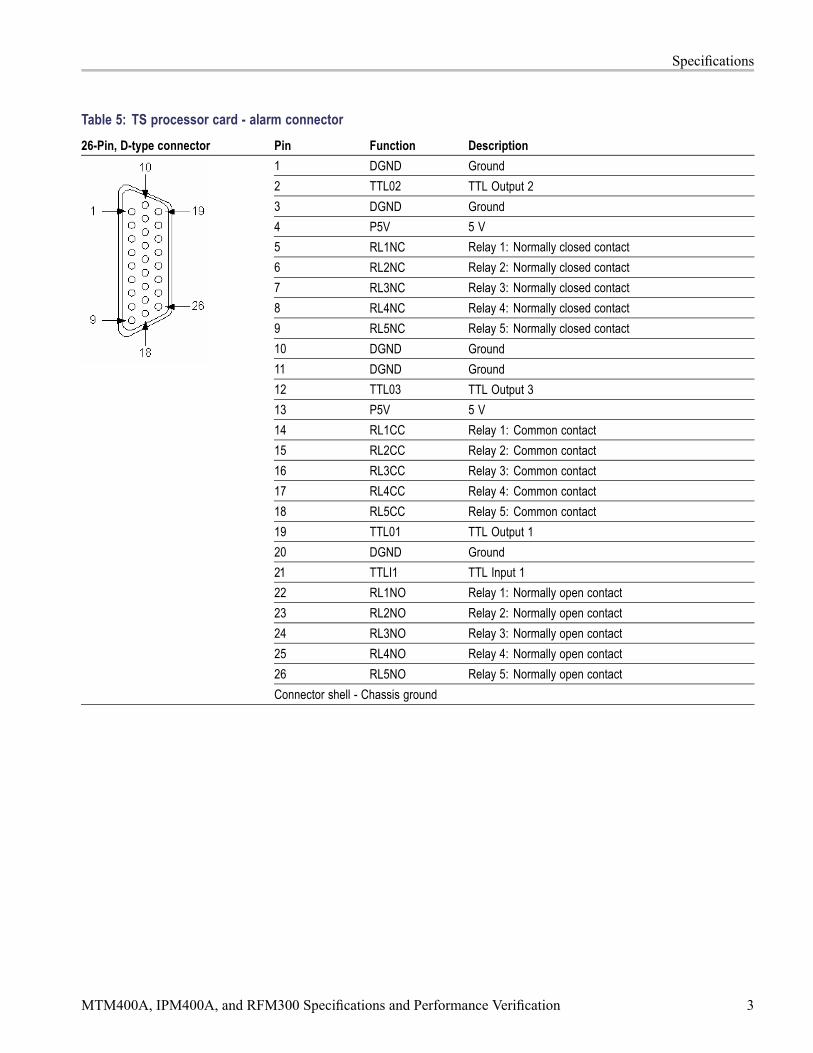
Table 5: TS processor card - alarm connector26-Pin, D-type connector Pin Function Description
1 DGND Ground2 TTL02 TTL Output 23 DGND Ground4 P5V 5 V5 RL1NC Relay 1: Normally closed contact6 RL2NC Relay 2: Normally closed contact7 RL3NC Relay 3: Normally closed contact8 RL4NC Relay 4: Normally closed contact9 RL5NC Relay 5: Normally closed contact10 DGND Ground11 DGND Ground12 TTL03 TTL Output 313 P5V 5 V14 RL1CC Relay 1: Common contact15 RL2CC Relay 2: Common contact16 RL3CC Relay 3: Common contact17 RL4CC Relay 4: Common contact18 RL5CC Relay 5: Common contact19 TTL01 TTL Output 120 DGND Ground21 TTLI1 TTL Input 122 RL1NO Relay 1: Normally open contact23 RL2NO Relay 2: Normally open contact24 RL3NO Relay 3: Normally open contact25 RL4NO Relay 4: Normally open contact26 RL5NO Relay 5: Normally open contactConnector shell - Chassis ground
MTM400A, IPM400A, and RFM300 Specifications and Performance Verification 3

Specifications
Table 6: TS processor card - alarmsCharacteristic ValueAlarm Relay
Number of relays 5Maximum Switching Current 1 AmpMaximum Switch Voltage 24 VDC
Contact Resistance 100 milli-Ω maxTTL Output Pins of the AlarmsOutput Connector
Output Type TTL open collector, requires external pull-up resistorLogic High Voltage 2.0 V minLogic Low Voltage 0.8 V max, sinking 100 mAMaximum Switching Current 100 mA
TTL Input Pins of the Alarms OutputConnector
Maximum Input Voltage 5.1 VLogic High Input Voltage 2.0 V minLogic Low Input Voltage 0.8 V max
+5 V Output, Pins 4 and 13 of theAlarms Output Connector
Output Voltage 4.9 V min, 5.1 V max, no loadMaximum Output Current 100 mAOutput Protection Fused, self resetting
Table 7: TS processor card - LTC connectorLTC 2-pin connector Pin Function Description
1 IN+2 IN-Connector shell - Chassis ground
Port SpecificationType Linear time code, SMPTE standard to ANSI/SMPTE 12M - 1995Input Voltage 2.0 V p-p differentially minimum
Table 8: TS processor card - Ethernet RJ-45 connectorCharacteristic DescriptionConnector 10/100 Base-T; RJ-45 Use only good quality screened cable; Cat 6
4 MTM400A, IPM400A, and RFM300 Specifications and Performance Verification

Specifications
Table 9: QAM Annex A interface card characteristicsCharacteristic DescriptionInput Frequency Range 51 MHz to 858 MHz, 62.5 kHz stepsModulation Format 16 QAM, 64 QAM, 256 QAM (compliant with DVB-C ETS 300 421)Modulation Baud Rate, QAM A 5.0 Mbaud/s minimum, 6.952 Mbaud/s maximumInput Signal Level -57 dBm (50 dBuV) to -27 dBm (80 dBuV), with a 16, 64, and 256 QAM input, providing five or
fewer Transport Error Flags in 10 seconds, which corresponds to a post FEC rate of 1e-8
Modulation Error Ratio (withequalizer)
38 dB min, with a 64 QAM input and 256 QAM input
Receiver Bandwidth, QAM A 8 MHz nominalInput Termination Impedance 75 Ω nominalInput Return Loss 6 dB min, 10 dB typical, 51 MHz to 858 MHzLoop Through Power Gain 1.5 dB to 4 dB typical, 51 MHz to 858 MHz typicalLoop Through Noise Figure 8 dB typicalLoop Through Output Return Loss Greater than 10 dB typical
Table 10: QAM Annex B2 interface card characteristicsCharacteristic DescriptionInput Frequency Range 88 MHz to 858 MHzInput Signal Level -64 dBm to -19 dBm (45 dBuV to 90 dBuV relative to 75 Ω ) (With either a 64 or 256 QAM
input, there are five or fewer Transport Error Flags in 11 seconds, which corresponds to a postFEC rate of 1e-8) ≥ -55 dBm to ensure compliance to EN 55103-2 immunity
Modulation Format 64 QAM, 256 QAM (compliant with ITU J-83 Annex B)Interleaving Mode Level 1 and Level 2 interleaving support compliant with all ITU J-83 Annex B, excluding I, J =
(128,7) and (128,8), and in 256 QAM excluding (8, 16) and (16, 8)Modulation Baud Rate 64 QAM: 5.056941 Mbaud/s 256 QAM: 5.360537 Mbaud/sSpectrum Polarity Demodulates both Normal and Inverted IF Spectrum.Receiver Bandwidth, QAM B 6 MHz nominalConnector Type F typeInput Termination Impedance 75 Ω nominalInput Return Loss 5 dB typicalUltimate Modulation Error Ratiowith Equalizer
≥ 37 dB with equalizer; typical
Table 11: QAM Annex B2 measurementsCharacteristic DescriptionRF Lock RF lock is indicated by LED and StatusInput Level (Signal Strength)(Typical)
Range: -64 dBm to -19 dBm (45 dBuV to 90 dBuV relative to 75 Ωs)Resolution: 1 dBAccuracy: ± 3 dB
MTM400A, IPM400A, and RFM300 Specifications and Performance Verification 5

Specifications
Table 11: QAM Annex B2 measurements (cont.)
Characteristic DescriptionEVM (Error Vector Magnitude)(Typical)
Display Range for 64 QAM: ≤ 1% to ≥ 5% rmsDisplay Range for 256 QAM: ≤ 1% to ≥ 2.5% rmsResolution: 0.1%Accuracy: "1%
MER (Modulation Error Ratio) withEqualizer (Typical)
Display Range:64 QAM: 22 dB to 37 dB256 QAM: 28 dB to 37 dBResolution: 0.1 dBAccuracy: ± 1 dB for MER < 25 dB; (plus-min) 3 dB for MER 25 dB to 34 dB(measured at -30 dBm input)
SNR (Signal to Noise Ratio)(Typical)
Display Range:64 QAM: 22 dB to 37 dB256 QAM: 28 dB to 37 dBResolution: 1 dBAccuracy: "1 dB for SNR < 25 dB; ± 3 dB for SNR 25 dB to 34 dB
BER (Bit Error Ratio) Pre-RS BER is displayedTEF (Transport Error Flag) Transport Error Flags (uncorrectable error count) in a 1 second window and 10 second window
are displayed.Constellation The RF constellation is displayed.
Table 12: QAM Annex C interface card characteristicsCharacteristic DescriptionInput Frequency Range 88 MHz to 858 MHz, 62.5 kHz stepsModulation Format 16 QAM, 64 QAM, 256 QAM (compliant with ITU J-83 Annex C)Modulation Baud Rate, QAM C 4.5 Mbaud/s min; 5.5 Mbaud/s maxInput Signal Level -57 dBm (50 dBuV) to -27 dBm (80 dBuV), with a 16, 64, and 256 QAM input, providing five or
fewer Transport Error Flags in 12 seconds, which corresponds to a post FEC rate of 1e-8
Modulation Error Ratio (withequalizer)
38 dB typical, with a 64 QAM input
Receiver Bandwidth, QAM C 6 MHz nominalInput Termination Impedance 75 Ω nominalInput Return Loss 6 dB min, 10 dB typical, 88 MHz to 858 MHz
Table 13: 8PSK/QPSK interface card characteristics with 8PSK inputCharacteristic DescriptionInput Frequency Range 950 MHz to 2150 MHz with 1 MHz step sizeInput Signal Amplitude Range -60 dBm to -30 dBm for a CBER of <1e-6
Modulation Format QPSK in accordance with ETSI EN 300 421Modulated Baud Rate 1 MBaud min, 30 MBaud maxTurbo Viterbi Values Supported 2/3, 3/4 (2.05), 3/4 (2.1), 5/6, 8/9
6 MTM400A, IPM400A, and RFM300 Specifications and Performance Verification

Specifications
Table 13: 8PSK/QPSK interface card characteristics with 8PSK input (cont.)
Characteristic DescriptionTurbo FEC Turbo codeConnector Style F-styleInput Termination Impedance 75 Ω nominalInput Return Loss 4 dB min, 950 MHz to 2050 MHz typicalLNB Supply Voltage Selectable; 13.0 V ± 1.5 V or 18.0 V (plus-min) 1.5 V, with 100 Ω, 5 watt resistor loadLNB Supply Maximum Current 200 mA maximumLNB 22 kHz Signaling Frequency 17.6 kHz min, 26.4 kHz max (22 kHz ± 20%)LNB 22 kHz Signaling Amplitude 600 mV p-p with 100 Ω loadUltimate Modulation Error Ratio(with equalizer)
26 dB with equalizer
Table 14: 8PSK/QPSK interface card characteristics with QPSK inputCharacteristic DescriptionInput Frequency Range 950 MHz to 2150 MHz with 1 MHz step sizeInput Signal Amplitude Range -60 dBm to -30 dBm for a CBER of <1e-6
Modulation Format QPSK in accordance with ETSI EN 300 421Modulated Baud Rate 1 MBaud min, 30 MBaud maxViterbi Values Supported 1/2, 2/3, 3/4, 5/6, 6/7, 7/8FEC In accordance with ETSI EN 300 421Turbo Viterbi Values Supported 1/2, 2/3, 3/4, 5/6, 7/8Turbo FEC Turbo codeConnector Style F-styleInput Termination Impedance 75 Ω nominalInput Return Loss 4 dB min, 950 MHz to 2050 MHz typicalLNB Supply Voltage Selectable; 13.0 V ± 1.5 V or 18.0 V (plus-min) 1.5 V, with 100 Ω, 5 watt resistor loadLNB Supply Maximum Current 200 mA maximumLNB 22 kHz Signaling Frequency 17.6 kHz min, 26.4 kHz max (22 kHz ± 20%)LNB 22 kHz Signaling Amplitude 600 mV p-p with 100 Ω loadUltimate Modulation Error Ratio(with equalizer)
26 dB with equalizer
Table 15: 8PSK and QPSK measurementsCharacteristic DescriptionRF Lock RF lock is indicated by LED and Status.Input Level (Signal Strength) Range: -60 dBm to -30 dBm; Resolution: 1 dBm; Accuracy: ± 5 dBm; typical
MTM400A, IPM400A, and RFM300 Specifications and Performance Verification 7

Specifications
Table 15: 8PSK and QPSK measurements (cont.)
Characteristic DescriptionEVM (Error Vector Magnitude) Display Range: ≤ 4.0% to ≥ 30.0% rms;
Resolution: 0.1%;Accuracy: ± 20% of reading; typical
MER (Modulation Error Ratio) withEqualizer
Display Range: 10 dB to 26 dB with equalizer;Resolution: 1 dB;Accuracy: ± 2 dB for range 10 dB to 20 dB; typical
SNR (Signal to Noise Ratio) Display Range: 5 dB to 35 dB; Resolution: 1 dB;Accuracy: ± 2 dB for range from 5 dB to 30 dB; typical
Pre Reed Solomon (RS) BER (BitError Rate)
Pre-RS BER is displayed.
Post RS BER and TEF (TransportError Flag)
Post Reed Solomon BER (TEF ratio), TEF rate, and number of Transport Error Flags (TEFcount) are displayed.
Constellation The RF constellation is displayed.
Table 16: DVB-S2 interface card characteristicsCharacteristic DescriptionInput Frequency Range 950 MHz to 2150 MHz with 1 MHz step sizeInput Signal Amplitude Range -60 dBm to -30 dBm for a CBER of <1e-6
Modulation Format QPSK in accordance with DVB-S (ETSI EN 300 421)Modulated Baud Rate 1 MBaud min, 60 MBaud maxViterbi Values Supported DVB–S: 1/2, 2/3, 3/4, 5/6, 6/7, 7/8
DVB-S2: 1/4, 1/3, 2/5, 1/2, 3/5, 2/3, 3/4, 4/5, 5/6, 8/9, 9/10FEC modes Viterbi and Reed-solomon in accordance with DVB-S.
LDPC (low density parity check) and BCH in accordance with DVB-S2.Short and Normal FEC blocks in accordance with DVB-S2.
Roll Off 0.2, 0.25, 0.35Connector Style F-styleInput Termination Impedance 75 Ω nominalInput Return Loss > 6 dB min, 950 MHz to 2150 MHz typicalLNB Supply Voltage Selectable; 13.0 V ± 1.5 V or 18.0 V ± 1.5 V, with 100 Ω , 5 watt resistor loadLNB Supply Maximum Current 200 mA maximumLNB 22 kHz Signaling Frequency 17.6 kHz min, 26.4 kHz max (22 kHz ± 20%)LNB 22 kHz Signaling Amplitude 800 mV p-p with 100 Ω loadLNB Mode DiSEqC 2 (Digital Satellite Equipment Control)
Table 17: DVB-S2 measurementsCharacteristic DescriptionRF Lock RF lock is indicated by LED and Status.
8 MTM400A, IPM400A, and RFM300 Specifications and Performance Verification

Specifications
Table 17: DVB-S2 measurements (cont.)
Characteristic DescriptionInput Level (Signal Strength) Range: -60 dBm to -30 dBm; Resolution: 1 dBm; Accuracy: ± 5 dBm; typicalEVM (Error Vector Magnitude) Display Range: ≤ 4.0% to ≥ 30.0% rms; Resolution: 0.1%; Accuracy: ± 20% of reading; typicalMER (Modulation Error Ratio) withEqualizer
Display Range: 10 dB to 30 dB with equalizer; Resolution: 1 dB; Accuracy: ± 2 dB for range10 dB to 28 dB; typical
CNR (Carrier to Noise Ratio) Display Range: 10 dB to 30 dB; Resolution: 1 dB; Accuracy: ± 2 dB for range from 10 dB to28 dB; typical
Phase Noise Display Range: 5º to 45º; Resolution: 1ºPre Viterbi BER Pre-Viterbi BER is displayed.Pre Reed Solomon (RS) BER (BitError Rate)
Pre-RS (Reed-Solomon) BER is displayed.
Pre LDPC BER Pre-LDPC (Low Density Parity Check) BER shall be displayed.Pre BCH BER Pre-BCH (Bose-Chaudhuri-Hocquengham) BER shall be displayedPost RS BER and TEF (TransportError Flag)
Post Reed-Solomon BER (TEF ratio), TEF rate, and number of Transport Error Flags(TEF count) are displayed.
Transmission Parameters All Coding and Modulation parameters are displayedConstellation The RF constellation is displayed.
Table 18: 8VSB interface card characteristicsCharacteristic DescriptionInput Frequency Range 54 MHz to 860 MHz, VHF/UHF channels 2 to 69 (to include low VHF frequencies)Input Signal Level -72 dBm to -6 dBm (-23 dBmV to +43 dBmV)
≥ -60 dBm to ensure compliance to EN 55103-2 immunityModulation Format 8VSB in accordance with ATSC A/53B.Receiver Bandwidth 6 MHzInput Termination Impedance 75 Ω nominalConnector Type F typeInput Return Loss 5 dB minimum; typical
Table 19: 8VSB measurementsCharacteristic DescriptionRF Lock RF lock is indicated LED and StatusInput Level (Signal Strength)(Typical)
Display Range: -72 dBm to -2 dBm relative to 75 Ω (-23 dBmV to +47 dBmV)Resolution: 1 dBAccuracy: ± 3 dB
EVM (Error Vector Magnitude)(Typical)
Display Range: ≤ 3.0% to ≥ 12.5% rmsResolution: 0.1%Accuracy: ± 20% of reading
MTM400A, IPM400A, and RFM300 Specifications and Performance Verification 9

Specifications
Table 19: 8VSB measurements (cont.)
Characteristic DescriptionEquivalent MER (Modulation ErrorRatio) with Equalizer (Typical)
Display Range: 17 dB to 31 dB with EqualizerResolution: 0.1 dBAccuracy: ± 1 dB for MER > 25 dB; (plus-min) 3 dB for MER 25 dB to 31 dB (Measured at-30 dBm input. For best MER accuracy, maintain the input signal level between -50 dBmand -15 dBm.)
SNR (Signal to Noise Ratio)(Typical)
Display Range: 15 dB to 35 dBResolution: 1 dBAccuracy: ± 1 dB for SNR < 25 dB; (plus-min) 3 dB for SNR 25 dB to 35 dB
BER Pre-RS BER, SER 1 second and 10 seconds windows values are displayed.TEF (Transport Error Flag) Transport Error Flags (uncorrectable error count) in a 1 second window and 10 second window
are displayed.Constellation Diagram The 8VSB constellation diagram is a display of I-data history with histograms (the IQ
constellation is not available). This is displayed as Symbol Distribution in the user interface.Echo Profile (Typical) Equalizer filter tap information is displayed.
Display Echo Level range: Normalized real tap values over the range of -1 to 1Display Delay range: -6.7 µs to 45.5 µs
10 MTM400A, IPM400A, and RFM300 Specifications and Performance Verification

Specifications
Table 20: COFDM interface card characteristicsCharacteristic DescriptionInput Frequency Range 50 MHz to 858 MHz (to include low VHF)Input Signal Amplitude Range The receiver delivers QEF (Quasi Error Free) operation over the following signal power
ranges: QPSK (4 QAM): -85 dBm to -10 dBm (24 dBuV to 99 dBuV)16 QAM: -80 dBm to -10 dBm (29 dBuV to 99 dBuV)64 QAM: -72 dBm to -15 dBm (37 dBuV to 94 dBuV) ≥ -60 dBm to ensure complianceto EN 55103-2 immunity
Compliance COFDM (DVB-T) receptions and demodulation, compliant with ETSI EN300-744, 2 K and8 K transmission modes
Tuning Resolution 166.7 kHz or smaller incrementsTuning Accuracy Better than ± 50 ppmChannel Bandwidth 6 MHz, 7 MHz, and 8 MHz (software selectable)Connector Style F-styleInput Termination Impedance 75 Ω nominalInput Return Loss 7 dB minimum, 50 MHz to 858 MHz; typicalModulation Schemes Supported QPSK (4 QAM), 16 QAM, and 64 QAM modulationTransmission Modes 2 K carriers and 8 K carriersHierarchical modulation All hierarchies will be supported, to include no hierarchy, and alpha = 1, 2 and 4.Viterbi puncture rates 1/2, 2/3, 3/4, 5/6, 7/8Guard Intervals 1/32, 1/16, 1/8, 1/4Spectrum Polarity The receiver will operate with both inverted and normal spectral polarity.Ultimate Modulation Error Ratio,with Equalizer
≥ 37 dB with equalizer; typical
Table 21: COFDM measurementsCharacteristic DescriptionOverall Receiver Lock Status Overall receiver lock status is indicated by an LED on the rear panel.Transmission Coding Parameters The receiver reports the current status of the following transmission parameters:
- QPSK/16, QAM/64, QAM encoding- 2K/8K Transmission mode- Hierarchy status (hierarchy on/off, alpha value)- Viterbi puncture rate - Guard Interval Value- Gross bit rate in the channel- Spectrum polarity (inverted/non inverted)
MTM400A, IPM400A, and RFM300 Specifications and Performance Verification 11

Specifications
Table 21: COFDM measurements (cont.)
Characteristic DescriptionInput Level (Signal Strength)(Typical)
Ranges, High Sensitivity mode:QPSK (4 QAM): -85 dBm to -10 dBm (24 dBuV to 99 dBuV) 16 QAM: -80 dBm to -10 dBm(29 dBuV to 99 dBuV)64 QAM: -72 dBm to -13 dBm (37 dBuV to 96 dBuV)Ranges, High Resolution mode:QPSK (4 QAM): -45 dBm to -10 dBm (64 dBuV to 99 dBuV)16 QAM: -45 dBm to -10 dBm (64 dBuV to 99 dBuV)64 QAM: -45 dBm to -13 dBm (64 dBuV to 96 dBuV)Resolution: 1 dBmAccuracy: ± 3 dBm
RF Carrier Offset Accuracy: ± 50 ppm, of the tuned frequency; typicalCarrier Power Distribution The carrier-by-carrier signal-to-noise power ratio is displayed. Channel Flatness in dB can be
viewed from spectrum display. Tilt in dB can be viewed from spectrum display.SNR (Signal to Noise Ratio)(Typical)
Display Range: 6 dB to 40 dB for QPSK (4 QAM): 11 dB to 40 dB for 16 QAM 16 dB to 40 dBfor 64 QAMResolution: 1 dBAccuracy: ± 1 dB to 30 dB SNR (measured at -30 dBm input in high resolution mode)
EVM (Error Vector Magnitude)(Typical)
Display Range: ≤ 1% to ≥ 30% rms, for QPSK ≤ 1% to ≥ 20% rms, 16 QAM ≤ 1% to ≥8.5% rms, 64 QAMResolution: 0.1%Accuracy: 1% (1 EVM unit), and additional ± 20% of reading
MER (Modulation Error Ratio) withEqualizer (Typical)
Both MER Peak and MER Average are displayed as measured across all carriers.Display Range: 6 dB to 37 dB for QPSK (4 QAM) 11 dB to 37 dB for 16 QAM 16 dB to 37 dBfor 64 QAMResolution: 0.1 dBAccuracy: ± 1 dB to 30 dB (Measured at -30 dBm input in High Resolution mode). For bestMER accuracy, use High Resolution mode, and maintain the input signal level between-45 dBm and -15 dBm.
Channel Equalization Status Channel estimate I and Q values for each carrier are displayed.Constellation The RF constellation is displayed.BER Pre-Viterbi BER and Pre Reed-Solomon BER values are displayed.Post RS BER and TEF (TransportError Flag)
Post Reed Solomon BER (uncorrectable error count) and number of Transport Error Flagsare displayed.
12 MTM400A, IPM400A, and RFM300 Specifications and Performance Verification
Specifications
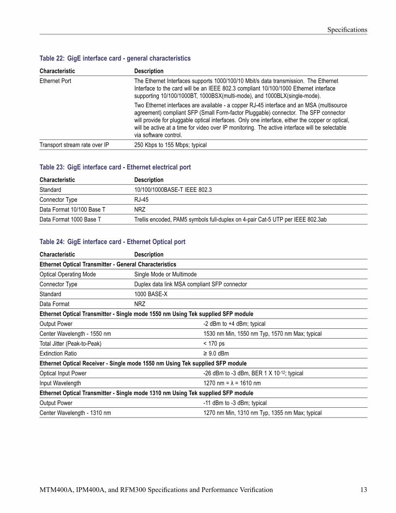
Table 22: GigE interface card - general characteristicsCharacteristic DescriptionEthernet Port The Ethernet Interfaces supports 1000/100/10 Mbit/s data transmission. The Ethernet
Interface to the card will be an IEEE 802.3 compliant 10/100/1000 Ethernet interfacesupporting 10/100/1000BT, 1000BSX(multi-mode), and 1000BLX(single-mode).Two Ethernet interfaces are available - a copper RJ-45 interface and an MSA (multisourceagreement) compliant SFP (Small Form-factor Pluggable) connector. The SFP connectorwill provide for pluggable optical interfaces. Only one interface, either the copper or optical,will be active at a time for video over IP monitoring. The active interface will be selectablevia software control.
Transport stream rate over IP 250 Kbps to 155 Mbps; typical
Table 23: GigE interface card - Ethernet electrical portCharacteristic DescriptionStandard 10/100/1000BASE-T IEEE 802.3Connector Type RJ-45Data Format 10/100 Base T NRZData Format 1000 Base T Trellis encoded, PAM5 symbols full-duplex on 4-pair Cat-5 UTP per IEEE 802.3ab
Table 24: GigE interface card - Ethernet Optical portCharacteristic DescriptionEthernet Optical Transmitter - General CharacteristicsOptical Operating Mode Single Mode or MultimodeConnector Type Duplex data link MSA compliant SFP connectorStandard 1000 BASE-XData Format NRZEthernet Optical Transmitter - Single mode 1550 nm Using Tek supplied SFP moduleOutput Power -2 dBm to +4 dBm; typicalCenter Wavelength - 1550 nm 1530 nm Min, 1550 nm Typ, 1570 nm Max; typicalTotal Jitter (Peak-to-Peak) < 170 psExtinction Ratio ≥ 9.0 dBmEthernet Optical Receiver - Single mode 1550 nm Using Tek supplied SFP moduleOptical Input Power -26 dBm to -3 dBm, BER 1 X 10-12; typicalInput Wavelength 1270 nm = λ = 1610 nmEthernet Optical Transmitter - Single mode 1310 nm Using Tek supplied SFP moduleOutput Power -11 dBm to -3 dBm; typicalCenter Wavelength - 1310 nm 1270 nm Min, 1310 nm Typ, 1355 nm Max; typical
MTM400A, IPM400A, and RFM300 Specifications and Performance Verification 13

Specifications
Table 24: GigE interface card - Ethernet Optical port (cont.)
Ethernet Optical Transmitter - Single mode 1310 nm Using Tek supplied SFP moduleTotal Jitter (Peak-to-Peak) < 170 psExtinction Ratio ≥ 9.0 dBmEthernet Optical Receiver - Single mode 1310 nm Using Tek supplied SFP moduleOptical Input Power -19 dBm to -3 dBm, BER 1 X 10-12; typicalInput Wavelength 1270 nm = λ = 1610 nmEthernet Optical Transmitter - Multimode 850 nm Using Tek supplied SFP moduleOutput Power -9.5 dBm to -2 dBm; typicalCenter Wavelength - 850 nm 830 nm Min, 850 nm Typ, 860 nm Ma; typicalTotal Jitter (Peak-to-Peak) < 170 psExtinction Ratio ≥ 9.0 dBmEthernet Optical Receiver - Multimode 850 nm Using Tek supplied SFP moduleOptical Input Power -17 dBm to 0 dBm, BER 1 X 10-12; typicalInput Wavelength 770 nm = λ = 860 nm
Table 25: GigE interface card - ASI inputCharacteristic DescriptionConnector BNCTransport Stream Rate 250 Kbps to 155 Mbps; typicalData Format Accepts both Burst and Packet mode ASI formatSignal Amplitude 2.0 Vp-p max; 200 mVp-p minTermination 75 Ω nominal, transformer coupledReturn Loss 10 dB min, 5 MHz to 270 MHzLink Rate 270 Mbaud ±3 100 ppm
Table 26: GigE interface card - ASI output (active loopthrough of ASI/SMPTE input or TS from GigE interface card)Characteristic DescriptionConnector BNCImpedance 75 Ω nominal, transformer coupledTransport Stream Rate 250 Kbps to 155 Mbps maxTransport Stream Smoothing Smoothing mechanism for the TS packets before retransmitting packets out on ASI portSignal Amplitude 600 mVp-p min, 1.0 Vp-p max into a 75 Ω loadReturn Loss 10 dB min at 270 MHz
14 MTM400A, IPM400A, and RFM300 Specifications and Performance Verification

Specifications
Table 27: GigE interface card - SMPTE310M input (loopthrough to ASI output)Characteristic DescriptionConnector BNCTermination 75 Ω nominal, transformer coupledData Format Bi-phase coded. Compliant with SMPTE310MInput Bit Rate 19,392,658.5 bps ±3 2.8 ppmSignal Amplitude 2.0 Vp-p max; 200 mVp-p minReturn Loss 10 dB min at 20 MHz
Power Source CharacteristicsTable 28: AC power source characteristicsCharacteristic DescriptionSource Voltage 100 VAC to 240 VAC
Frequency Range 50 Hz/60 HzPower Consumption 1 A maxPeak Inrush Current 7.2 A peak at 240 VAC, 50 HzFuse Rating Mains fuse is 3.15 A, 250 V (Not operator replaceable. Refer servicing to qualified service
personnel.)
Table 29: Transport stream card batteriesCharacteristic DescriptionQuantity 2 (In single carrier)Voltage 3 VCapacity 210 mAhContinuous Discharge (Maximum) 3 mAOverall Dimensions (Single cell)
Height 3.2 mm (0.13 in)Width (Diameter) 20 mm (0.79 in)
Battery Type Tektronix part number: 146-0096-xx
MTM400A, IPM400A, and RFM300 Specifications and Performance Verification 15

Specifications
Environmental CharacteristicsTable 30: Environmental characteristicsCharacteristic DescriptionTemperature
Operating +5 °C to +40 °CNonoperating -10 °C to +60 °C
HumidityOperating 10% to 80% relative humidity up to 31 °C Above 31 °C, decreasing linearly to 50% at 40 °CNonoperating 10% to 95% relative humidity, noncondensing
AltitudeOperating 0 m to 3000 m (9800 ft.)Nonoperating 0 m to 12000 m (40000 ft.)
Mechanical (Physical) CharacteristicsTable 31: Mechanical characteristicsCharacteristic DescriptionClassification Transportable platform also intended for 19-inch rack mounted applications, 1RU high.Overall Dimensions
Height 44 mm (1.73 in) (1RU)Width 430 mm (17.13 in)Depth 600 mm (23.62 in)
Required Clearance Top and bottom: 0 mm; Sides: Standard 19 in rack mountWeight 6.0 kg (13.3 lbs); fully loadedPackaged Dimensions
Height 241 mm (9.5 in)Width 590 mm (23.1 in)Depth 760 mm (30 in)
Weight (Packaged) 9 kg (19.7 lbs)
16 MTM400A, IPM400A, and RFM300 Specifications and Performance Verification

Performance VerificationTo verify that the DTV monitor is operating correctly, perform the followingprocedure.
RequirementsThe DTV monitor must be connected to a network and have a valid IP address asdescribed in the MTM400A, IPM400A, and RFM300 Quick Start User Manuals.
The client PC must satisfy the minimum requirements. (See Table 1 on page 1.)
Procedure1. Connect the DTV monitor to an Ethernet network.
2. Power on the DTV monitor and wait for the instrument initialization tocomplete.
3. On a client PC (connected to the same network and subnet mask as the DTVmonitor), launch the Microsoft Internet Explorer Web browser.
NOTE. This procedure describes how to access the DTV monitor RUI using theMicrosoft Internet Explorer Web browser. The RUI can also be accessed using theTektronix Web Monitoring Systems Manager (WebMSM). This is described in theWebMSM User Manual, Tektronix part number 077-0116-xx.
4. In the Web browser address bar, enter the network identity or the IPaddress of the DTV monitor, for example: http://TSMonitor01 orhttp://111.222.333.444.
5. Press Enter. A Java applet is downloaded from the DTV monitor andlaunched. The file size is approximately 1.5 MB; the download time willdepend on the network speed and traffic.
CAUTION. The Java applet will not run unless a temp directory is properlyconfigured on the PC. A temp directory is set up by default in the Windows XPoperating system; previous operating systems may require operator action.
The Java applet will not run unless the Sun Java Virtual Machine is installed.Type java -version at the command prompt to verify that it is installed and that theversion is 1.6.0_10 or greater. If it is not installed, you can download the latestversion from the Sun Web site, www.java.com\getjava.
If you have to update the Java version on the PC, you will need to restart thisprocedure at step 3.
MTM400A, IPM400A, and RFM300 Specifications and Performance Verification 17

Performance Verification
6. In the Connect to MTM Device dialog box, select the Login Type from thedrop-down list, Administrator or User.
7. Enter the password for the Login Type you selected in step 6. The defaultpassword for Administrator is tek; there is no default password for User.
8. Click Connect to start the connection process.
9. Read the End User License Agreement if it appears, and then click I Accept.
10. When the DTV monitor RUI opens, click Device in the button bar to displaythe Device Information view. (See Figure 1.)
11. In the Device Information view, verify that the Application Firmware Versionis 3.2 or greater.
12. If the DTV monitor connects and presents the RUI, and displays the correctapplication firmware version in the Device Information window, then theinstrument is operating normally.
Figure 1: DTV monitor RUI display
18 MTM400A, IPM400A, and RFM300 Specifications and Performance Verification
Related Documents