MTLT305D/M Series User’s Manual _____________________________________________________________________________________ Doc# 7430-3305-09 Page 1 ACEINNA, Inc. email: [email protected], website: www.aceinna.com MTLT305D/M SERIES USER MANUAL Document Part Number: 7430-3305-09

Welcome message from author
This document is posted to help you gain knowledge. Please leave a comment to let me know what you think about it! Share it to your friends and learn new things together.
Transcript

MTLT305D/M Series User’s Manual
_____________________________________________________________________________________
Doc# 7430-3305-09 Page 1
ACEINNA, Inc.
email: [email protected], website: www.aceinna.com
MTLT305D/M SERIES USER MANUAL Document Part Number: 7430-3305-09

MTLT305D/M Series User’s Manual
_____________________________________________________________________________________
Doc# 7430-3305-09 Page 2
Date Document
Revision
Firmware
Applicability
Description Author
June 17, 2018 -01 V19.1.4 Initial Release FL / JF
March 7,
2019
-02 V19.1.5 Update for new FW release. BIT Tables,
theory of operation, and Appendix A
(dbc File Example)
XD / JF
April 9, 2019 -03 V19.1.5 Add Recommended Mounting Hardware
and torque specification. Removed dbc
file appendix
JF
June 17, 2019 -04 V19.1.51 Correct RS232 Pinout
Add CAN Data Message upper byte
definition
JF
Sept 19, 2019 -05 V19.1.51 Updated description of status
information reported on CAN bus
AB
Nov 12, 2019 -06 V 19.1.6 Added requests for retrieval of specific
data messages and parameters on
demand from unit on CAN bus
AB
Mar, 1, 2020 -07 V 19.1.6 Added Metal Housing (M) version
mechanical drawing. Changed all
reference of MTLT305D to
MTLT305D/M. Removed references to
nonexistent appendices
JF
Sept 22, 2020 -09 V19.20 Added new CAN packet for HR
accelerometers data.
Added J1939 SS1 packet
Added option for configuring unit
behavior by user from CAN bus.
Updated description of changing unit
behavior over CAN bus.
Added user behavior switch to swap x
and y in ACS and ARI Packet.
Added option to provide corrected or
raw rate.
Added auto baud detection on CAN bus.
Added unit reset command as an Option
of algorithm reset and save
configuration command
Added enforcement to check first byte of
Request command to be 0.
Added Appendix E on CAN Commands.
Added User Behavior switch for
acceleration data in NWU orientation
AB / JF /
SH

MTLT305D/M Series User’s Manual
_____________________________________________________________________________________
Doc# 7430-3305-09 Page 3
Added option to use raw or filtered
acceleration for EKF gain control.
Added Algorithm Control CAN packet
and Algorithm Control parameters to
RS232 Port Configuration Fields
Description of corrected rate used in
linear acceleration detection logic added
WARNING
Aceinna has developed this product exclusively for commercial applications. It has not been tested for, and
Aceinna makes no representation or warranty as to conformance with, any military specifications or that
the product is appropriate for any military application or end-use. Additionally, any use of this product for
nuclear, chemical, biological weapons, or weapons research, or for any use in missiles, rockets, and/or
UAV's of 300km or greater range, or any other activity prohibited by the Export Administration Regulations,
is expressly prohibited without the written consent of Aceinna and without obtaining appropriate, US export
license(s) when required by US law. Diversion contrary to U.S. law is prohibited.
©2018 Aceinna, Inc. All rights reserved. Information in this document is subject to change without
notice.
Aceinna is a registered trademark of Aceinna Inc. Other product and trade names are trademarks or
registered trademarks of their respective holders.

MTLT305D/M Series User’s Manual
_____________________________________________________________________________________
Doc# 7430-3305-09 Page 4
Table of Contents
Introduction .............................................................................................................................. 8
Manual Overview ........................................................................................................................... 8
Overview of the MTLT305D/M Dynamic Inclination and Acceleration Sensor ........................... 9
Interface .................................................................................................................................. 10
Electrical Interface........................................................................................................................ 10
Connector and Mating Connector ......................................................................................... 10
Power Input and Power Input Ground ................................................................................... 11
CAN Serial Interface ............................................................................................................. 11
RS232 Serial Data Interface .................................................................................................. 11
Mechanical Interface .................................................................................................................... 12
Recommended Mounting Hardware and Torque .................................................................. 12
Theory of Operation ............................................................................................................... 13
MTLT305D/M Series Default Coordinate System ...................................................................... 16
Axis Orientation Settings ...................................................................................................... 17
Digital Filter ................................................................................................................................. 17
Acceleration Filter Settings ................................................................................................... 17
Rate Sensor Filter Settings .................................................................................................... 17
CAN Port Interface Definition ................................................................................................ 19
SAEJ1939 ..................................................................................................................................... 19
ECU’s Address ...................................................................................................................... 19
Address Claim ....................................................................................................................... 20
Baud Rate .............................................................................................................................. 20
Get Commands ...................................................................................................................... 21
Set Commands ...................................................................................................................... 28
Data Packets .......................................................................................................................... 34
DBC File ....................................................................................................................................... 37
RS232 Port Interface Definition ............................................................................................. 38
General Settings............................................................................................................................ 38
Number Formats ........................................................................................................................... 38
Packet Format ............................................................................................................................... 39
Packet Header ........................................................................................................................ 39
Packet Type ........................................................................................................................... 39
Payload Length ...................................................................................................................... 40

MTLT305D/M Series User’s Manual
_____________________________________________________________________________________
Doc# 7430-3305-09 Page 5
Payload .................................................................................................................................. 40
16-bit CRC-CCITT ............................................................................................................... 40
Messaging Overview ............................................................................................................. 40
MTLT305D/M Standard RS232 Port Commands and Messages ........................................... 42
Link Test. ...................................................................................................................................... 42
Ping Command ...................................................................................................................... 42
Ping Response ....................................................................................................................... 42
Echo Command ..................................................................................................................... 42
Echo Response ...................................................................................................................... 42
Interactive Commands .................................................................................................................. 42
Get Packet Request ............................................................................................................... 43
Algorithm Reset Command ................................................................................................... 43
Algorithm Reset Response .................................................................................................... 43
Error Response ...................................................................................................................... 43
Output Packets (Polled) ................................................................................................................ 44
Identification Data Packet ..................................................................................................... 44
Version Data Packet .............................................................................................................. 44
Test 0 (Detailed BIT and Status) Packet ............................................................................... 45
RS232 Output Packets (Polled or Continuous) ............................................................................ 45
Angle Data Packet 2 (Default MTLT305D/M Data) ............................................................ 45
MTLT305D/M Advanced RS232 Port Commands ................................................................ 47
Configuration Fields ..................................................................................................................... 47
Continuous Packet Type Field ...................................................................................................... 48
Digital Filter Settings ................................................................................................................... 48
Orientation Field ........................................................................................................................... 48
User Behavior Switches ............................................................................................................... 50
Commands to Program Configuration Over RS232 ..................................................................... 51
Write Fields Command ......................................................................................................... 51
Set Fields Command ............................................................................................................. 52
Read Fields Command ................................................................................................................. 53
Read Fields Response ................................................................................................................... 53
Get Fields Command .................................................................................................................... 54
Get Fields Response.................................................................................................................. 54
Bootloader .............................................................................................................................. 56

MTLT305D/M Series User’s Manual
_____________________________________________________________________________________
Doc# 7430-3305-09 Page 6
Bootloader Initialization ............................................................................................................... 56
Firmware Upgrade Command ...................................................................................................... 56
UART Interface ..................................................................................................................... 56
Warranty and Support Information ......................................................................................... 58
Customer Service.......................................................................................................................... 58
Contact Directory ......................................................................................................................... 58
Return Procedure .......................................................................................................................... 58
Authorization ......................................................................................................................... 58
Identification and Protection ................................................................................................. 58
Sealing the Container ............................................................................................................ 59
Marking ................................................................................................................................. 59
Appendix A: Installation and Operation of NAV-VIEW over RS232........................................... 60
Appendix B: Sample RS232 Packet-Parser Code .......................................................................... 72
Appendix C: RS232 Sample Packet Decoding .............................................................................. 80
Appendix D: Advanced RS232 Port BIT ....................................................................................... 81
Appendix E: CAN Command Summary ........................................................................................ 87

MTLT305D/M Series User’s Manual
_____________________________________________________________________________________
Doc# 7430-3305-09 Page 7
About this Manual
The following annotations have been used to provide additional information.
NOTE
Note provides additional information about the topic.
EXAMPLE
Examples are given throughout the manual to help the reader understand the terminology.
IMPORTANT
This symbol defines items that have significant meaning to the user
WARNING
The user should pay particular attention to this symbol. It means there is a chance that physical harm
could happen to either the person or the equipment.
The following paragraph heading formatting is used in this manual:
1 Heading 1
1.1 Heading 2
1.1.1 Heading 3
1.1.1.1 Heading 4
Normal

MTLT305D/M Series User’s Manual
_____________________________________________________________________________________
Doc# 7430-3305-09 Page 8
Introduction
Manual Overview
This manual provides a comprehensive introduction to ACEINNA’s MTLT305D/M Series Dynamic
Inclination and Acceleration Sensing Family of products. As the functionality of the different products
within the family are identical (only the performance specs are different), for simplicity all references will
be to the MTLT305D/M. For users wishing to get started quickly, please refer to the two-page Best
Practices Guide available online at www.aceinna.com. Table 1 highlights the content in each section and
suggests how to use this manual.
Table 1 Manual Content
Manual Section Who Should Read?
Section 1:
Overview
All customers should read sections 1.1 and 1.2.
Section 2:
Interface
Customers designing the electrical and mechanical interface to the
MTLT305D/M series products should read Section 2.
Section 3:
Theory of Operation
All customers should read Section 3.
Section 4
CAN Port Interface
Customers designing the software interface to the MTLT305D/M series
products CAN Port should review Section 4
Section 0 - 7:
RS232 Port Interface
Customers designing the software interface to the MTLT305D/M series
products RS232 Port should review Sections 0 - 7.
Section 8:
Bootloader
Customers upgrading firmware should review Sections 8.
Section 9:
Warranty and Support
Customers who need the support information should review Section 9.

MTLT305D/M Series User’s Manual
_____________________________________________________________________________________
Doc# 7430-3305-09 Page 9
Overview of the MTLT305D/M Dynamic Inclination and Acceleration Sensor
This manual introduces the use of ACEINNA’s MTLT305D/M Series Dynamic Inclination and
Acceleration Sensing products listed in Table 2. This manual is intended to be used as a detailed technical
reference and operating guide. ACEINNA’s MTLT305D/M Series products combine the latest in high-
performance commercial MEMS (Micro-electromechanical Systems) sensors and digital signal
processing techniques to provide a small, rugged and cost effective solution for accurately sensing pitch
and roll in dynamic applications.
Table 2 MTLT305D/M Series Feature Description
Product Features
MTLT305D/M Pitch, Roll, 3D ±8 g acceleration, 3D ±400 deg/s Bias Corrected
Rate
The MTLT305D/M Series is based on ACEINNA’s fourth generation of MEMS-based Inertial Systems,
building on over a decade of field experience, and encompassing thousands of deployed units and
millions of operational hours in a wide range of land, marine, airborne, and instrumentation applications.
At the core of the MTLT305D/M Series is a rugged 6-DOF (Degrees of Freedom) MEMS inertial sensor
cluster that is common across all members of the MTLT305D/M Series and many ACEINNA IMU,
AHRS and INS products. The 6-DOF MEMS inertial sensor cluster includes three axes of MEMS angular
rate sensing and three axes of MEMS linear acceleration sensing. These sensors are based on rugged, field
proven silicon micromachining technology. Each sensor within the cluster is individually factory
calibrated for temperature and non-linearity effects during ACEINNA’s manufacturing and test process
using automated thermal chambers and precision rate tables.
Coupled to the 6-DOF MEMS inertial sensor cluster is a high performance microprocessor that utilizes
the inertial sensor measurements to accurately compute attitude (pitch and roll). The attitude algorithm
utilizes a multi-state Extended Kalman Filter (EKF) to correct for drift errors and estimate sensor bias
values.
Another unique feature of the MTLT305D/M Series is the extensive field configurability of the units.
This field configurability allows the MTLT305D/M Series of Inertial Systems to satisfy a wide range of
applications and performance requirements with a single mass produced hardware platform. Parameters
that can be configured include baud rate, low pass filter settings (acceleration and rate sensors) packet
type, update rate, and defining of custom orientation.
The MTLT305D/M firmware is designed to be field upgradable so units in the field can be upgraded to
take advantage of new features or algorithm improvements that may be available in future firmware
revision releases.
The MTLT305D/M Series is available packaged cast metal housing or in a light-weight, rugged, IP69K
sealed plastic enclosure with nickel plated brass mounting bushings designed for cost-sensitive
commercial applications requiring a robust solution that can be exposed to the elements. Mounting
configuration is the same for both versions. The MTLT305D/M can be configured to output data over a
CAN Port and / or a RS232 serial port. The MTLT305D/M RS232 output data port is supported by
ACEINNA’s NAV-VIEW 3.X, a powerful PC-based operating tool that provides complete field
configuration, diagnostics, charting of sensor performance, and data logging with playback.

MTLT305D/M Series User’s Manual
_____________________________________________________________________________________
Doc# 7430-3305-09 Page 10
Interface
Electrical Interface
Connector and Mating Connector
The MTLT305D/M connector is an AMPSEAL16 6-pos defined in Figure 1
Figure 1 MTLT305D/M Interface Connector
The mating connector is: TE Connectivity 776531-1 or equivalent, which is currently listed at the
following web address: http://www.te.com/usa-en/product-776531-1.html
The definitions of connector pins are in Table 3.
Table 3 MTLT305D/M Interface Connector Pin Definition
Pin Signal
1 CAN H
2 CAN L
3 Ground
4 RS232 RX
5 RS232 TX
6 Power

MTLT305D/M Series User’s Manual
_____________________________________________________________________________________
Doc# 7430-3305-09 Page 11
Power Input and Power Input Ground
Power is applied to the MTLT305D/M on pin 6, and ground is Pin 3; The MTLT305D/M accepts an
unregulated 5 to 32 VDC input. It is reverse polarity and ESD protected internally. It is designed to be
compatible with 12 V and 24 V power environments of Heavy Equipment and Passenger Vehicle power
systems.
CAN Serial Interface
The MTLT305D/M is equipped with a CAN 2.0 electrical interface and is compliant to the SAE J1939
protocol standard. CAN 120 ohm termination resistor is not present
Baud Rate: The default CAN baud rate setting is 250kb/s. The MTLT305D/M supports baud rates
125kb/s, 250kb/s, 500kb/s and 1000kb/s. The CAN baud rate can be changed and permanently saved by
the user using the RS232 port and NAV-VIEW 3.x SW running on a PC. See the section 4.1.3.
CAN Address: The default CAN address is 0x80. The MTLT305D/M has address claiming capability. In
the event there is a conflict with another module on the bus with the same address, it will attempt to claim
a new address and save it in non-volatile memory. The CAN address can also be changed and
permanently saved by the user using the RS232 port and NAV-VIEW 3.x SW running on a PC. See the
section 4.1.1.
RS232 Serial Data Interface
The default baud rate of RS232 interface is 57600bps. MTLT305D/M also supports 38400, 115200 and
230400bps baud rates and can be changed or saved permanently in non-volatile memory through NAV-
VIEW.
The RS-232 standard defines the voltage levels that correspond to logical one and logical zero levels for
the data transmission and the control signal lines. Valid signals are either in the range of +3 to +15 volts
or the range −3 to −15 volts with respect to the "Common Ground" (GND) pin.
A "3-wire" RS-232 connection consisting only of transmit data, receive data, and ground, is commonly
used.

MTLT305D/M Series User’s Manual
_____________________________________________________________________________________
Doc# 7430-3305-09 Page 12
Mechanical Interface
The MTLT305D/M mechanical interfaces are defined by the outline drawings in Figure 2
MTLT305D – Plastic Housing MTLT305M – Metal Housing
Figure 2 MTLT305D/M Outline Drawing
Mating Connector: TE Connectivity 776531-1 or equivalent. See Figure 1
Recommended Mounting Hardware and Torque
Use 4 - M5 Alloy Steel Socket Head Screws to secure the MTLT305D/M.
It is recommended to use standard M5 washer with outer diameter of 10mm, lock washer and Loctite 242
thread lock.
The washer outer diameter must NOT be larger than the outer diameter of the bushing (11mm).
MTLT305D – Plastic Housing: Torque the screws to 2.37 N-m (21 inch-pounds).
MTLT305M – Metal Housing: Torque the screws to 5.0 N-m (44.25 inch-pounds).

MTLT305D/M Series User’s Manual
_____________________________________________________________________________________
Doc# 7430-3305-09 Page 13
Theory of Operation
The MTLT305D/M Series are a family of dynamic inclination and acceleration sensors. They provide
dynamic pitch and roll, 3D linear acceleration, and 3D estimated rate measurement data (Pitch and Roll
rates are bias corrected, Yaw is not).
Figure 3 shows the MTLT305D/M Series hardware block diagram. At the core of the MTLT305D/M
Series is a rugged 6-DOF (Degrees of Freedom) MEMS inertial sensor cluster that is common across all
members of the MTLT305D/M Series. The 6-DOF MEMS inertial sensor cluster includes three axes of
MEMS angular rate sensing and three axes of MEMS linear acceleration sensing. These sensors are based
on rugged, field proven silicon micromachining technology. Each sensor within the cluster is individually
factory calibrated using ACEINNA’s automated manufacturing process. Sensor errors compensated for
are temperature bias, scale factor, non-linearity and misalignment effects using a proprietary algorithm
from data collected during manufacturing. Accelerometer and rate gyro sensor bias shifts over
temperature (-40 ⁰C to +85 ⁰C) are compensated and verified using calibrated thermal chambers and
precision rate tables.
The acceleration sensors have a full-scale range (FSR) of ±78 ms-2, and the rate sensors have a FSR of
400 degrees/s. The large FSR ensures that the sensors are not over-ranged in the application. Both the
acceleration and rate sensors are over sampled at 800 Hz, and digitally processed through a 3rd order 50
Hz low-pass filter (LPF), which serves as a digital anti-aliasing filter as the cutoff frequency is half of the
maximum output data rate of 100 Hz. It is not user configurable. Additionally, the over sampling and
primary LPF combine to eliminate higher frequency vibration and impulse energy providing greater
accuracy in high-vibration environments.
The 50 Hz filtered data is then corrected for temperature related errors and non-linearity by ACEINNA’s
proprietary compensation algorithm using data collected during ACEINNA’s calibration process.
The corrected data is then presented to the user configurable LPFs. The acceleration and rate sensors’
LPFs can be set independently. The default setting for the rate data is 25 Hz and the default setting for the
acceleration data is 5 Hz.
This dataset is used to generate the dynamic roll and pitch estimation and are stabilized by the using the
accelerometers as a long-term gravity reference. Internally, the algorithm solves for roll and pitch at a
200 Hz rate, enabling the MTLT305D/M to continuously maintain the dynamic roll and pitch data as well
as the 3D linear acceleration and 3D estimated rate data. The Yaw estimation (RS232 only) is a free
integrating yaw angle measurement that is not stabilized by a magnetometer or compass heading. As
shown in the software block diagram Figure 4, after the Sensor Calibration block, the temperature
corrected and filtered data is passed into Integration to Orientation block. The Integration to Orientation
block integrates body frame sensed angular rate to orientation at a fixed 200 times per second within the
MTLT305D/M Series products. For improved accuracy and to avoid singularities when dealing with the
Euler angles, a quaternion formulation is used in the algorithm to provide attitude propagation.
As also shown in the software block diagram, the Integration to Orientation block receives drift
corrections from the Extended Kalman Filter (EKF) or Drift Correction Module. In general, rate sensors
and accelerometers suffer from bias drift, misalignment errors, acceleration errors (g-sensitivity),
nonlinearity (square terms), and scale factor errors. The largest error in the orientation propagation is
associated with the rate sensor bias terms. The EKF module provides an on-the-fly calibration for drift
errors, including the rate sensor bias, by providing corrections to the Integration to Orientation block and
a characterization of the gyro bias state. In the MTLT305D/M, the internally computed gravity reference
vector provides a reference measurement for the EKF when the MTLT305D/M is in quasi-static motion
to correct roll and pitch angle drift and to estimate the X and Y gyro rate bias. Because the gravity vector
has no horizontal component, the EKF has no ability to estimate either the yaw angle error or the Z gyro

MTLT305D/M Series User’s Manual
_____________________________________________________________________________________
Doc# 7430-3305-09 Page 14
rate bias. The MTLT305D/M adaptively tunes the EKF feedback in order to best balance the bias
estimation and attitude correction with distortion free performance during dynamics when the object is
accelerating either linearly (speed changes) or centripetally (false gravity forces from turns). Because
centripetal and other dynamic accelerations are often associated with yaw rate, the MTLT305D/M
maintains a low-passed filtered yaw rate signal and compares it to the turnSwitch threshold field (user
adjustable). When the user platform to which the MTLT305D/M is attached exceeds the turnSwitch
threshold yaw rate, the MTLT305D/M lowers the feedback gains from the accelerometers to allow the
attitude estimate to coast through the dynamic situation with primary reliance on angular rate sensors.
This situation is indicated by the softwareStatus→turnSwitch status flag. Using the turn switch maintains
better attitude accuracy during short-term dynamic situations, but care must be taken to ensure that the
duty cycle of the turn switch generally stays below 10% during the vehicle mission. A high turn switch
duty cycle does not allow the system to apply enough rate sensor bias correction and could allow the
attitude estimate to become unstable.
The MTLT305D/M algorithm has two major phases of operation. The first phase of operation is the
initialization phase. During the initialization phase, the MTLT305D/M is expected to be stationary or
quasi-static in order to get a good initial estimation of the roll and pitch angles, and X, Y rate sensor bias.
The initialization phase lasts less than 2 seconds, and the initialization phase can be monitored in the
softwareStatus BIT transmitted by default in each RS232 measurement packet. After the initialization
phase, the MTLT305D/M operates in the dynamic mode to continuously estimate and correct for roll and
pitch errors, as well as to estimate X and Y rate sensor bias.
If a user wants to reset the algorithm or re-enter the initialization phase, sending the algorithm reset
command, ‘AR’, will force the algorithm into the reset phase.
The MTLT305D/M outputs digital measurement data over the CAN or RS232 port at a selectable fixed
rate (100, 50, 25, 20, 10, 5 or 2 Hz) or on as requested basis.
In addition to the configurable baud rate, packet rate, axis orientation, and sensor low-pass filter settings,
the MTLT305D/M provides additional advanced settings, which are selectable for tailoring the
MTLT305D/M to a specific application requirement.
Figure 3 MTLT305D/M Series Hardware Block Diagram
6-DOF Sensor Cluster
X / Y / Z
Gyros
X / Y / Z
Accelerometers
High-Speed Sampling and Anti-
aliasing LPF
Sensor Compensation / User Selectable
Filtering
+
Kalman Filter Attitude and Rate
Estimation
CAN
RS232
System Digital Outputs and Inputs
Pitch and Roll
X / Y / Z Acceleration
Roll / Pitch / Yaw Rate
Built-In-Test Temperature
Sensor

MTLT305D/M Series User’s Manual
_____________________________________________________________________________________
Doc# 7430-3305-09 Page 15
Figure 4 shows the software block diagram. As shown in the software block diagram, the MTLT305D/M
Series has a unit setting and profile block which configures the algorithm to user and application specific
needs. This feature is one of the more powerful features in the MTLT305D/M Series architecture as it
allows the MTLT305D/M Series to work in a wide range of commercial applications by settings different
modes of operation for the MTLT305D/M Series.
Figure 4 MTLT305D/M Series Software Block Diagram
The common aiding sensor for the drift correction for the attitude (i.e., roll and pitch only) is a 3-axis
accelerometer. This is the default configuration for the MTLT305D/M products.
X / Y / Z Body Accelerometers
6-DOF Sensor Cluster
Sensor Calibration
Axes Rotation
Kalman Filter and Dynamic State Model
Gravity Reference Turn Rate (Internal
Computation)
Free Integrate TurnSwitch Threshold
X / Y / Z Body Rates
200Hz Signal Proc. Chain
Extended Kalman Filter (EKF) Drift Correction Module
MTLT305D/M
Pitch, Roll
3D Acceleration
3D Rate
Integration to
Attitude
Unit Settings & Profile*
Communication Settings
Axes Orientations
Low-Pass Filtering
Turn Switch Threshold
Free Integrate
Restart on Over-range
Dynamic Motion
Programmable BIT Alerts
Aiding Sensors
Built In Test & Status Data Available to User
Measurement Data Available to User (Fixed Rate or Polled)
Status Packet (T0)

MTLT305D/M Series User’s Manual
_____________________________________________________________________________________
Doc# 7430-3305-09 Page 16
MTLT305D/M Series Default Coordinate System
The MTLT305D/M Series Inertial System default coordinate systems are shown in Figure 5. As with
many elements of the MTLT305D/M Series, the coordinate system is configurable with either NAV-
VIEW or by sending the appropriate serial commands over the CAN or RS232 port. These configurable
elements are known as Advanced Settings. This section of the manual describes the default coordinate
system settings of the MTLT305D/M Series when it leaves the factory.
Figure 5. MTLT305D/M Default Coordinate Frame
The axes form an orthogonal SAE right-handed coordinate system. Acceleration is positive when it is
oriented towards the positive side of the coordinate axis. For example, with a MTLT305D/M Series
product sitting on a level table, it will measure zero g along the x and y-axes and -1 g along the z-axis.
Normal Force acceleration is directed upward, and thus will be defined as negative for the MTLT305D/M
Series z-axis.
The angular rate sensors are aligned with these same axes. The rate sensors measure angular rotation rate
around a given axis. The rate measurements are labeled by the appropriate axis. The direction of a
positive rotation is defined by the right-hand rule. With the thumb of your right hand pointing along the
axis in a positive direction, your fingers curl around in the positive rotation direction. For example, if the
MTLT305D/M Series product is sitting on a level surface and you rotate it clockwise on that surface, this
will be a positive rotation around the z-axis. The x and y-axis rate sensors would measure zero angular
rates, and the z-axis sensor would measure a positive angular rate.
Pitch is defined positive for a positive rotation around the y-axis (pitch up). Roll is defined as positive for
a positive rotation around the x-axis (roll right). Yaw is defined as positive for a positive rotation around
the z-axis (turn right).
“The angles are defined as standard Euler angles using a 3-2-1 system. To rotate from the earth-level
frame to the body frame, yaw first, then pitch, and then roll.
+X Axis
+Y Axis
+Z Axis
+Z Axis goes out the bottom
of the unit
Roll
Pitch

MTLT305D/M Series User’s Manual
_____________________________________________________________________________________
Doc# 7430-3305-09 Page 17
Axis Orientation Settings
The MTLT305D/M gives users the ability to set the axes orientation by selecting which axis aligns with
the base axes as well as the sign. The only constraint is the axes must conform to a right-hand definition.
The available settings are described in Section 7.4. The specific selections are provided in Table 36 and
Table 58. The default setting is (+Ux, +Uy, +Uz).
Refer to CAN Protocol Section 4.1.5.6 for instructions on changing the orientation for your application
over the CAN bus.
Refer to RS232 Protocol Section 7.4 for instructions on changing the orientation for your application over
the RS232 Port.
Digital Filter
There are two Independent User filters available for filtering the accelerometer and the rate-sensor
signals. The Filters are 2nd order Butterworth filters that can be set to 50, 40, 25, 20, 10, 5, and 2 Hz cutoff
frequencies. One setting applies to all three of a sensor’s axes.
Acceleration sensor Filter default is 5 Hz. Rate Sensor default is 25 Hz.
Acceleration Filter Settings
Decreasing the accelerometer filter cutoff frequency will reduce transmission of the accelerometer noise
to the algorithm and enable the system to better estimate roll and pitch angles (as well as rate-sensor bias)
under noisy idle-conditions (such as vibration caused by engine noise). The filter will not have a large
effect on the estimate of the roll and pitch angles during motion, as the role of the accelerometer is
reduced during motion and angles are estimated by integrating the rate-sensor signal.
Refer to CAN Protocol Section 4.1.5.5 for instructions on changing the acceleration sensor filter for your
application over the CAN bus.
Refer to RS232 Protocol Section 7.3 for instructions on changing the acceleration sensor filter for your
application over the RS232 Port
Rate Sensor Filter Settings
Decreasing the rate-sensor filter cutoff frequency will reduce transmission of the vibrational noise to the
algorithm and enable the system to generate less noisy roll and pitch angle estimates under noisy
conditions (such as vibration caused by engine noise). However, very low cutoff frequency settings can
increase lag in the signal, which may affect system performance. Settings must be made based on system
requirements.
Refer to CAN Protocol Section 4.1.5.5 for instructions on changing the rate sensor filter setting for your
application over the CAN bus.
Refer to RS232 Protocol Section 7.3 for instructions on changing the rate sensor filter for your application
over the RS232Port
NOTE on Filter Settings
Why change the filter settings? Generally, there is no reason to change the low-pass filter settings on the
MTLT305D/M Series Inertial Systems. However, when a MTLT305D/M Series product is installed in an
environment with a lot of vibration, it can be helpful to reduce the vibration-based signal energy and noise
prior to further processing on the signal. Installing the MTLT305D/M in the target environment and
reviewing the data with NAV-VIEW can be helpful to determine if changing the filter settings would be
helpful. Although the filter settings can be helpful in reducing vibration based noise in the signal, low

MTLT305D/M Series User’s Manual
_____________________________________________________________________________________
Doc# 7430-3305-09 Page 18
filter settings (e.g., <5Hz) also reduce the bandwidth of the signal, i.e. can wash out the signals containing
the dynamics of a target. Treat the filter settings with caution.

MTLT305D/M Series User’s Manual
_____________________________________________________________________________________
Doc# 7430-3305-09 Page 19
CAN Port Interface Definition
The CAN interface of MTLT supports the CAN protocol versions 2.0B. It has been designed to manage
high numbers of incoming messages efficiently, and meets the priority requirements for transmit message.
MTLT305D/M supports a maximum baud rate 1Mbps. The default setting is 250kbs.
MTLT305D/M default configuration includes no CAN termination.
SAEJ1939
MTLT supports CAN’s higher layer protocol, SAEJ1939, managing the communication within network.
J1939 is a set of standards defined by SAE. The physical layer (J1939/11) describes the electrical
interface to the bus. The data link layer (J1939/21) describes the rules for constructing a message,
accessing the bus, and detecting transmission errors. The application layer (J1939/71 and J1939/73)
defines the specific data contained within each message sent across the network.
J1939 uses the 29-bit identifier defined within the CAN 2.0B protocol shown in Table 4.
Table 4. Structure of a 29-bit identifier
Priority Reserved Data
Page
PDU Format PDU
Specific
Source
Address
3 bits 1 bits 1bit 8 bits 8 bits 8 bits
The first three bits of the identifier are used for controlling a message’s priority during the arbitration
process. A value of zero has the highest priority. Higher priority values are typically given to high-speed
control messages.
The next bit of the identifier is reserved for the future use and should be set to zero for transmitted
message.
The next bit of the identifier is the data page selector.
The PDU format determines whether the message can be transmitted with a destination address or if the
message is always transmitted as a broadcast message.
The interpretation of the PDU specific field changes based on the PF value:
• If the PF is between 0 and 239, the message is addressable and the PS field contains a
destination address
• If the PF is between 240 and 255, the message can only be broadcast. The PS field
contains a Group Extension.
The term Parameter Group Number (PGN) is used to refer to the value of the Reserve bit, DP, PF, and PS
fields combined into a single 18-bit value.
The last 8 bits of the identifier contain the address of the device transmitting the message.
ECU’s Address
Each device on the network will be associated with one address. The device address defines a specific
communications source or destination for messages. The default CAN address for the MTLT305D/M is
128.

MTLT305D/M Series User’s Manual
_____________________________________________________________________________________
Doc# 7430-3305-09 Page 20
Address 255 is reserved as a global address for broadcast and address 254 is reserved as the “null
address” used by devices that have not yet claimed an address or failed to claim an address.
Address Claim
In general, most addresses are pre-assigned and used immediately upon power up. In order to permit
J1939 to accommodate future devices and functions, which have not yet been defined, a procedure has
been specified for dynamically assigning addresses. Each device must announce which address it is
associated with.
MTLT’s firmware contains dynamic address assignment and these devices, which might be expected to
encounter address conflict, must support this capability. In order to speed up identity process, most ECUs
are associated with the preferred address. If the preferred address is already used by another ECU on the
same network, the device can attempt to claim another address.
Baud Rate
4.1.3.1 Manual Baud Rate Configuration
The J1939 network is intended to be a single, linear, shielded twisted pair of wires running around the
vehicle to each ECU. The default data rate of J1939 is 250kb/s. A typical message containing 8 bytes is
128 bits long, which in time is approximately 500 microseconds. MTLT supports manual configuration of
baud rate to 125kb/s, 250kb/s, 500kb/s and 1000 kb/s.
The baud rate of MTLT is configurable through the RS232 interface using NAV-VIEW.
4.1.3.2 Auto Baud Detection
Autobaud detection supports 250kb/s, 500kb/s and 1000kb/s.
The MTLT305D is configured at the factory for a baud rate of 250kbps. This value is stored in non-
volatile memory. When power is applied (or any time the power is cycled), the unit will select a starting
baud rate, which will be the last baud rate stored in non-volatile memory, and will put itself into Silent
Baud Discovery Mode.
In this mode, the unit will listen silently, without transmitting or asserting the Acknowledge bit, and uses
an automated error counter mechanism incorporated into its CAN peripheral controller. It checks the error
counter at 10ms intervals. At each 10ms interval, the unit checks both the error counter, and the CAN
FIFO buffer for a valid 29-bit message identifier. One of three cases can occur:
1. If there is a valid 29-bit message identifier, and the error counter is at zero, the unit will lock to the current
baud rate, and store this value in non-volatile memory.
2. If the error counter crosses a programmable threshold (default = 20 counts), or if the error counter increases
for three sequential 10ms periods, then the unit will switch to the next supported baud rate, clear the
message FIFO buffer, and continue monitoring at this new baud rate.
3. Otherwise the unit will continue monitoring at 10ms intervals, at the current baud rate, until case 1 or case
2 occurs.
Note that an 11-bit standard frame message will not be considered valid while the unit is in Silent Baud
Discovery Mode.
The list of supported baud rates is 250kbps, 500kbps, and 1Mbps, and the MTLT305D will cycle
indefinitely in that order, beginning with the last value stored in non-volatile memory, until the baud rate
is successfully detected.

MTLT305D/M Series User’s Manual
_____________________________________________________________________________________
Doc# 7430-3305-09 Page 21
In normal operation (after Baud Discovery Mode has ended), the unit will maintain a counter which keeps
a running count of CAN errors. Each time it detects an RX error, it increments the error counter by +1.
Each time it detects a TX error, it increments the error counter by +8; each time it successfully transmits
or receives an error free message, it decrements the error counter by 1. If the error counter reaches 255,
the unit will go to the “bus off” state, and enter silent Baud Discovery Mode (as described above).
Get Commands
Get commands are used for another ECUs on the network to collect the corresponding message from
MTLT. All of the commands are formed by a Request message of SAEJ1939-21 PGN number 60159.
The format of the request message payload provided in Table 5.
Table 5. The format of request message payload
Byte 0 Byte 1 Byte 2
PGN MSB PGN PGN LSB
4.1.4.1 Firmware Version
MTLT responds to a J1939 request PGN 65242 packet with message, containing 5-byte payload. Table 6
shows the format of firmware version packet.
Table 6. The format of firmware version response packet
Priority PGN PF PS SA Payload
6 65242 254 218 5 bytes
The payload consists of current firmware version in MTLT. See Table 7.
Table 7. Firmware version response payload
Byte 0 Byte 1 Byte 2 Byte 3 Byte 4
Major Minor Patch Stage Build
4.1.4.2 Rate of periodic data packets
Upon receiving request for parameter with PGN 65365 (current rate value of periodic packets) from
another ECU on the network MTLT responds with a packet, containing 2-byte payload. Table 8 shows
the format of the response.
Table 8. The format of packet rate divider response packet
Priority PGN PF PS SA Payload
6 65365 255 85 2 bytes
NOTE: PS value for this command can be changed using command “Bank of PS numbers” PS Bank 1.
The payload consists of address of requesting unit and current rate value of periodic packets in MTLT.
See Table 9.

MTLT305D/M Series User’s Manual
_____________________________________________________________________________________
Doc# 7430-3305-09 Page 22
Table 9. Packet rate response payload
Byte 0 Byte 1
DA Packets rate (see p. 4.1.5.3)
4.1.4.3 Enabled Periodic Data Packets
Upon receiving request for parameter with PGN 65366 (currently enabled periodic data packet types)
from another ECU on the network MTLT responds with a packet, containing 2-byte payload. Table 10
shows the format of the response.
Table 10. The format of data packet types response packet
Priority PGN PF PS SA Payload
6 65366 255 86 2 bytes
NOTE: PS value for this command can be changed using command “Bank of PS numbers” PS Bank 1.
The response payload consists of address of requesting unit and bitmask which represents currently
enabled periodic packet types. See Table 11.
Table 11. Packet types response payload
Byte 0 Byte 1
DA Packet types (see p. 4.1.5.4)
It is also possible to request from MTLT specific data packet. The request payload should contain PGN of
the specific data packet (see 4.1.6.1, 4.1.6.2 and 4.1.6.3)
4.1.4.4 Active Digital Filters
Upon receiving request for parameter with PGN 65367 (about currently active digital filters) from another
ECU on the network MTLT responds with a packet, containing 3-byte payload. Table 12 shows the
format of the response.
Table 12. The format of digital filters response packet
Priority PGN PF PS SA Payload
6 65367 255 87 3 bytes
NOTE: PS value for this command can be changed using command “Bank of PS numbers” PS Bank 1.
The response payload consists of address of requesting unit and currently active filters for accelerometers
and rate sensors data. See Table 13.
Table 13. Active digital filters response payload
Byte 0 Byte 1 Byte 2
DA Rate sensor filter cutoff
frequency (see p. 4.1.5.5)
Accelerometer filter cutoff
frequency (see p. 4.1.5.5)

MTLT305D/M Series User’s Manual
_____________________________________________________________________________________
Doc# 7430-3305-09 Page 23
4.1.4.5 Current unit orientation
Upon receiving request for parameter with PGN 65368 (about current unit orientation settings) from
another ECU on the network MTLT responds with a packet, containing 3-byte payload. Table 14 shows
the format of the response.
Table 14. The format of unit orientation response packet
Priority PGN PF PS SA Payload
6 65368 255 88 3 bytes
NOTE: PS value for this command can be changed using command “Bank of PS numbers” PS Bank 1.
The response payload consists of address of requesting unit and current unit orientation settings. See
Table 15.
Table 15. Unit orientation response payload
Byte 0 Byte 1 Byte 2
DA Orientation (MSB) (see p. 4.1.5.6) Orientation (LSB)
4.1.4.6 ECU’s ID
The ID is a 64-bit long label, which gives every ECU a unique identity, following the definition in
SAEJ1939-81.
Table 16 shows the format of ID response packet.
Table 16. The format of ID response packet
Priority PGN PF PS SA Payload
6 64965 253 197 8 bytes
4.1.4.7 Hardware BIT
Upon receiving request for parameter with PGN 65362 (hardwareBit status request) from another ECU on
the network, MTLT responds with a packet with a 2-byte payload. Table 17 shows the format of the
hardwareBit response packet.
Table 17. The format of hardwareBit response packet
Priority PGN PF PS SA Payload
6 65362 255 82 2 Bytes
NOTE: PS value for this command can be changed using command “Bank of PS numbers” PS Bank 0.
Table 18 gives the payload details of the packet.

MTLT305D/M Series User’s Manual
_____________________________________________________________________________________
Doc# 7430-3305-09 Page 24
Table 18. hardwareBit response
Bit Description Value Solution
0 MasterFail 0=normal, 1=fatal error has occurred or
unit is in very beginning stage of
initialization. The BIT will normally
clear after initialization (~0.7s). If the
BIT is not cleared the unit is broken.
Power cycle can be tried to recover.
If not recovered after power cycle
unit should be replaced.
1 HW Error 0=normal, 1=internal hardware error.
Indicates sensors initialization or self-
test error.
Power cycle can be tried to recover
unit. If not recovered after power
cycle the unit should be replaced.
2 SW Error 0=normal, 1=internal gyro error, unit in
the initialization stage (see Table 11),
or algorithm error. The bit will
normally clear after initialization (~2s).
If the bit is not cleared after
initialization, the unit is broken.
Power cycle can be tried to recover
unit. If not recovered after power
cycle the unit should be replaced.
3 - 15 Reserved Reserved
4.1.4.8 Software BIT
Upon receiving request for parameter with PGN 65363 (softwareBit status request) from another ECU on
the network, MTLT responds with a packet with 6-bit payload. Table 19 shows the format of the
softwareBit response packet.
Table 19. The format of softwareBit response
Priority PGN PF PS SA Payload
6 65363 255 83 2 Bytes
NOTE: PS value for this command can be changed using command “Bank of PS numbers” PS Bank 0.
Table 20 shows the content and definition of the packet.
Table 20. softwareBit response payload
Bit Description Value Solution
0 softwareError 0=normal, 1=internal software error.
Redundant to SW error bit in table 9.
Either bit can be monitored for
SW error detection.
1 algorithmError 0=normal, 1=error. Set during
algorithm initialization or sensor data
over range. In of case of set during
initialization, bit normally clear after
initialization (~2s). In case of over-
range, bit is cleared after over-range
condition removed. EKF will converge
to correct the solution, or algorithm can
be reset.
Algorithm can be reset using
command which can be sent
over CAN bus (PGN 65360) or
unit can be power cycled.

MTLT305D/M Series User’s Manual
_____________________________________________________________________________________
Doc# 7430-3305-09 Page 25
2 dataError 0=normal, 1=error. This bit is
redundant with bit 5.
If conditions persist after few
power cycles unit is broken and
needs to be replaced
3 Initialization 0=normal, 1= Algorithm is in the
initialization stage and unit is not ready.
Bit will be cleared after initialization is
complete (~2s).
If set bit persists after few
power cycles unit can be
considered broken and needs to
be replaced.
4 overRange 0=normal, 1= Indicates an over range
event, (rotation exceeding 400 dps or
acceleration exceeding 8g. It is cleared
when condition is removed.
EKF will converge to correct solution
or Algorithm can be reset. If condition
persists when system is not moving
after power cycle – unit is considered to
be damaged and needs to be replaced.
Algorithm can be reset using
command which can be sent
over CAN bus (PGN 65360) or
by power cycling unit.
5 Reserved Reserved
6 CalibrationCRC
Err
0=normal, 1=incorrect calibration CRC
or EEPROM write in progress.
Unit needs to be reset (power
cycled). If state persists after
power cycle – unit considered
to be damaged and needs to be
replaced.
7 – 15 Reserved Reserved
4.1.4.9 Status
Upon receiving request for parameter with PGN 65364 (status request) from another ECU on the network,
MTLT responds with a packet with 9-bit status message.
Table 21 shows the format of unit status response message.
Table 22 shows the contents and definition of unit status response payload.
Table 21. The format of sensor status
Priority PGN PF PS SA Payload
6 65364 255 84 2 bytes
NOTE: PS value for this command can be changed using command “Bank of PS numbers” PS Bank 0.

MTLT305D/M Series User’s Manual
_____________________________________________________________________________________
Doc# 7430-3305-09 Page 26
Table 22. Sensor Status Bits Field
Bit Description Value
0 masterStatus 0=normal, 1=hardware, sensor or
software alert
1 hardwareStatus 0=normal, 1=programmable alert
2 softwareStatus 0=normal, 1=programmable alert
3 sensorStatus 0=normal, 1=programmable alert
4 Reserved Reserved
5 Reserved Reserved
6 Reserved Reserved
7 unlockedEEPROM 0=locked, 1=unlocked
8 algorithmInit 0=normal, 1=in initial mode
9 Reserved Reserved
10 Aceinna_attitude_only_algo 0=normal, 1=programmable alert
11 turnSwitch 0=off, 1=yaw rate greater than
turnSwitch threshold
12 SensoroverRange 0=not asserted, 1=asserted (when
Asserted unit should be reset)
13 Reserved Reserved
14 Reserved Reserved
15 Reserved Reserved
4.1.4.10 Unit behavior
Upon receiving request for parameter with PGN 65369 (about current unit behavior configuration) from
another ECU on the network MTLT responds with a packet, containing 3-byte payload. Table 23 shows
the format of the unit behavior response packet.
Table 23 The format of unit behavior response packet
Priority PGN PF PS SA Payload
6 65369 255 89 3 bytes
NOTE: PS value for this command can be changed using command “Bank of PS numbers” PS Bank 1.
The response payload consists of address of requesting unit and unit behavior bitmask. See Table 24.

MTLT305D/M Series User’s Manual
_____________________________________________________________________________________
Doc# 7430-3305-09 Page 27
Table 24 The format of unit behavior response payload
Byte
Number
Selected Unit Behavior type
0 DA
1 Enable behavior bitmask:
Bit 0 – restart on over range
Bit 1 – dynamic motion
Bit 2 – uncorrected rates in ARI message
Bit 3 – swap x and y in ARI and ACS message
Bit 4 – autobaud detection mode
Bit 5 – Reserved
Bit 6 – enable NWU accelerometer frame
Bit 7 – raw accelerometer signal used to detect linear
acceleration
2 Bit 0 – use raw rate to predict acceleration
Bits 1:7 - Reserved
4.1.4.11 Algorithm control
The MTLT305D responds to a J1939 request PGN 65371 (Algorithm control) packet with a message
containing an 8-byte payload. Table 25 shows the format of this Algorithm Control response.
Table 25. The format of the algorithm control response
Priority PGN PF PS SA Payload
6 65371 255 91 8 bytes
Table 26. Algorithm control response payload
Byte Description Value Comment
0 Address of Unit Address of
destination
1 Reserved
2 Limit for rate integration
time LSB
Value in milliseconds From 10 to 10000 3 Limit for rate integration
time MSB
4 Limit for accelerometer
switch delay LSB Value in milliseconds
From 10 to 10000 5 Limit for accelerometer
switch delay MSB
6 Coefficient of reduced Q LSB Scale 0.0001 per lsb From 0.0001 to 1 7 Coefficient of reduced Q MSB

MTLT305D/M Series User’s Manual
_____________________________________________________________________________________
Doc# 7430-3305-09 Page 28
Set Commands
Set commands are used for other ECUs to configure MTLT on the network. All the commands are
broadcast messages with a destination address. The receivers will decode the payload and decide to ignore
the message meant for another ECU.
4.1.5.1 Configuration Save
The command is issued by an ECU on the network to the destination unit who is requested to save the
current configuration in RAM to EEPROM. The receiver will send a response back and notify the sender
that save command has been executed successfully or not. If Request field equals 2 unit will reset itself
after sending back the response.
Table 27 shows the format of the save configuration command. Table 28 is the description of save
configuration command payload.
Table 27. The Format of Save Configuration
Priority PGN PF PS SA Payload
6 65361 255 81 3 bytes
Table 28. Save Configuration Command Payload
Byte Description Value
0 Request or Response 0 =Request, 1=Response, 2 = Reset
1 Address of Unit
being saved
Address of destination
2 Success or failure 0=failure, 1=success
4.1.5.2 Algorithm Reset
The algorithm reset command is issued by an ECU on the network to the destination unit who is
requested to reset algorithm. The receiver will send a response back and notify the sender that the re-
initialization of algorithm has been executed successfully or not. If Request field equals 2 unit will reset
itself after sending back the response. Table 29 shows the format of the algorithm reset command.
Table 29. The format of algorithm reset command
Priority PGN PF PS SA Payload
6 65360 255 80 3 bytes
The description of the algorithm reset data field is the same as the save configuration shown data field
shown in Table 28.
NOTE: PS value for this command can be changed using command “Bank of PS numbers” PS Bank 0.
4.1.5.3 Packet Rate Divider
MTLT broadcasts three types of data packet, slope sensor information 2, angular rate data and linear
acceleration data, defined in Table SPNs & PGNs of SAEJ1939-DA. The default ODR of data packets is
100Hz. Packet rate divider command is used to change the ODR setting. The 1st byte of the payload is the

MTLT305D/M Series User’s Manual
_____________________________________________________________________________________
Doc# 7430-3305-09 Page 29
destination address and the 2nd byte of the payload sets the new ODRs. Table 30 shows the format of
packet rate divider command. The values of packet rate divider are defined in Table 31.
Table 30. The format of packet rate divider command
Priority PGN PF PS SA Payload
6 65365 255 85 2 bytes
NOTE: PS value for this command can be changed using command “Bank of PS numbers” PS Bank 1.
Table 31. Packet Rate Divider Field Definition
Byte Value Packet broadcasting rate
0 Quiet mode
1 100Hz (default)
2 50Hz
4 25Hz
5 20Hz
10 10Hz
20 5Hz
25 4Hz
50 2Hz
4.1.5.4 Data Packet Type
The MTLT305D/M’s data packet type follows SAEJ1939-DA Table SPNs & PGN. Users can choose any
combination of such output packets as slope sensor information 2 (PGN 61481), angular rate information
(PGN 61482) acceleration sensors (PGN 61485), high resolution acceleration sensors (PGN 65388), slope
sensor information 1 (PGN 61449).
The 1st byte of the payload is the destination address and the 2nd byte of the payload describes the packet
type to be set. Table 32 shows the format of data packet type command.
NOTE: PS value for this command can be changed using command “Bank of PS numbers” PS Bank 1.
Table 32. The format of Data Packet Type command
Priority PGN PF PS SA Payload
6 65366 255 86 2 bytes
The 2nd byte is a bitmask and used to select which data messages are to be transmitted. To select specific
message type set specific bit to 1. Any combination of messages can be selected for transmission. See
Table 33.

MTLT305D/M Series User’s Manual
_____________________________________________________________________________________
Doc# 7430-3305-09 Page 30
Table 33. Data Packet Type Field Definition (second payload byte)
Bit Number Selected Data Packet Type
0 SSI2
1 Angular Rate
2 Acceleration
3 SSI
4 HR Acceleration
4.1.5.5 Digital Filter
Users can change the frequencies of low-pass filters applied onto rate sensor or accelerometer. The
supported frequencies settings are: 2, 5, 10, 20, 25, 40, and 50 Hz. The frequencies are changed by the
command issued by another ECU on the network.
The 1st byte of the payload is the destination address and the 2nd or 3rd byte is the values of low-pass filter
frequency to be set to either rate sensor or accelerometer. Table 34 shows the format of digital filter
selection command.
1st byte: destination address
2nd byte is to set low pass cutoff for rate sensor. Cutoff Frequency choices are 0, 2, 5, 10, 20, 25, 40 and
50Hz
3rd byte is to set low pass cutoff for accelerometer. Cutoff Frequency choices are 0, 2, 5, 10, 20, 25, 40
and 50Hz
NOTE: PS value for this command can be changed using command “Bank of PS numbers” PS Bank 1.
Table 34. The format of digital filter change command
Priority PGN PF PS SA Payload
6 65367 255 87 3 bytes
4.1.5.6 Orientation
Users may change the coordinate system of MTLT via the command issued by another ECU on the
network. The 1st byte of payload is the destination address and the next 2 bytes define the values of the
orientation expected to be changed.
Table 35. Table 35 shows the format of unit orientation control command.
Table 35. The format of the unit orientation command
Priority PGN PF PS SA Payload
6 65368 255 88 3 bytes
Table 36 describes the possible values of the orientation.

MTLT305D/M Series User’s Manual
_____________________________________________________________________________________
Doc# 7430-3305-09 Page 31
Table 36. Possible values of the orientation
Orientation Field Value X Axis Y Axis Z Axis
0x0000 +Ux +Uy +Uz
0x0009 -Ux -Uy +Uz
0x0023 -Uy +Ux +Uz
0x002A +Uy -Ux +Uz
0x0041 -Ux +Uy -Uz
0x0048 +Ux -Uy -Uz
0x0062 +Uy +Ux -Uz
0x006B -Uy -Ux -Uz
0x0085 -Uz +Uy +Ux
0x008C +Uz -Uy +Ux
0x0092 +Uy +Uz +Ux
0x009B -Uy -Uz +Ux
0x00C4 +Uz +Uy -Ux
0x00CD -Uz -Uy -Ux
0x00D3 -Uy +Uz -Ux
0x00DA +Uy -Uz -Ux
0x0111 -Ux +Uz +Uy
0x0118 +Ux -Uz +Uy
0x0124 +Uz +Ux +Uy
0x012D -Uz -Ux +Uy
0x0150 +Ux +Uz -Uy
0x0159 -Ux -Uz -Uy
0x0165 -Uz +Ux -Uy
0x016C +Uz -Ux -Uy
NOTE: PS value for this command can be changed using command “Bank of PS numbers” PS Bank 1.
4.1.5.7 Unit behavior
The user can choose any combination of MTLT305D behaviors. Table 37 shows the format of the unit
behavior command.
Table 37. The format of Unit Behavior command
Priority PGN PF PS SA Payload
6 65369 255 89 6 bytes
The first payload byte is destination address.
The next 3 payload bytes used to enable/disable specific flavors of unit behavior. To affect specific
feature set specific bit to 1. Any combination of bits can be selected. Unit behavior settings can be
permanently saved. See Table 38 for user behavior bit definitions.
NOTE: PS value for this command can be changed using command “Bank of PS numbers” PS Bank 1.

MTLT305D/M Series User’s Manual
_____________________________________________________________________________________
Doc# 7430-3305-09 Page 32
Table 38. Unit behavior payload
Byte Selected Unit Behavior type
0 DA
1 Enable behavior bitmask:
Bit 0 – enable restart on over range
Bit 1 – enable dynamic motion
Bit 2 – use uncorrected rates in ARI message
Bit 3 – swap x and y in ARI and ACS message
Bit 4 – enable auto baud detection mode
Bit 5 – Reserved
Bit 6 – enable NWU accelerometer frame
Bit 7 – use raw accelerometer signal to detect linear acceleration
2 Bit 0 – use raw rate to predict acceleration
Bits 1:7 - Reserved
3 Disable behavior bitmask (overrides enable behavior settings if sent in
the same message):
Bit 0 – disable restart on over range
Bit 1 – disable dynamic motion
Bit 2 – disable usage of uncorrected rates in ARI message
Bit 3 – disable swap x and y in ARI and ACS message
Bit 4 – disable auto baud detection mode
Bit 5 – Reserved
Bit 6 – disable NWU accelerometer frame (use NED frame)
Bit 7 – do not use raw accelerometer signal to detect linear acceleration
4 Disable behavior bitmask (overrides enable behavior settings if sent in
the same message):
Bit 0 – use raw rate to predict acceleration (default - disabled)
Bits 1:7 - Reserved
5 New Unit address (valid address from 128 to 247). Will become active
after save command issued and unit will go through reset/power cycle.
4.1.5.8 Algorithm Control
The user can adjust certain algorithm parameters which can improve MTLT305D performance.
Table 39 shows the format of the algorithm control command.
Table 39. The format of algorithm control command
Priority PGN PF PS SA Payload
6 65371 255 91 8 bytes

MTLT305D/M Series User’s Manual
_____________________________________________________________________________________
Doc# 7430-3305-09 Page 33
Table 40. Algorithm control command payload
Byte Description Value Comment
0 Address of Unit Address of
destination
1 Reserved
2 Limit for rate integration
time LSB
Value in milliseconds From 10 to 10000 3 Limit for rate integration
time MSB
4 Limit for accelerometer
switch delay LSB
Value in milliseconds From 10 to 10000 5 Limit for accelerometer
switch delay MSB
6 Coefficient of reduced Q LSB Scale 0.0001 per lsb From 0.0001 to 1 7 Coefficient of reduced Q MSB
4.1.5.9 Bank of PS numbers
Users may change the default PS numbers inside MTLT if the pre-configured values have already been
used in their system. PS numbers include hardware bit, software bit, status, packet rate etc. The two
commands below are issued by user’s ECU and sent to MTLT, which will change the corresponding PS
values. Table 41 and Table 42 shows the format of these two commands. MTLT will decode the two
incoming packets and switch the default PS numbers to the values assigned by users. The new PS
numbers will take effect immediately and but also can be saved in non-volatile memory by the command
“Configuration Save” and will retain their values after powering cycle.
Table 41. The format of PS Bank0 command
Priority PGN PF PS SA Payload
6 65520 255 240 8 bytes
Bank0 payload contains 8 bytes and each of bytes is the newly assigned PS number to Get or Set
commands. The values at byte 0, 2, 3, 4, 5 are new PS numbers of algorithm reset, hardware bit, software
bit, status request, and HR acceleration. The remaining bytes are reserved.
Table 42. The format of PS Bank1 command
Priority PGN PF PS SA Payload
6 65521 255 241 8 bytes
Bank1 payload contains 8 bytes and each of bytes is the newly assigned PS number to set command. The
values of bytes 0, 1, 2, 3, 4 are the new PS numbers of packet rate type, digital filter, orientation, user
behavior and algorithm control. The remaining bytes, 5-7, are reserved.
NOTE: PS values in these commands can be chosen within range 64 - 127.
NOTE: User can restore default PS values by sending all zeroes in payload of these commands. Then issue
“Configuration save” command and recycle power or send “Algorithm reset” command with active
reset option.

MTLT305D/M Series User’s Manual
_____________________________________________________________________________________
Doc# 7430-3305-09 Page 34
Data Packets
MTLT outputs five different data packets. These packets are slope sensor information 2 and 1, angular
rate and acceleration sensor defined by SAEJ1939-DA and a custom high resolution acceleration packet.
4.1.6.1 Slope Sensor Information 2
The payload contains 8 bytes in little-endian mode and follows up the definition of SLOT 294 and
SAEad11 found in SAEJ1939-DA. The first 24-bit is the pitch value and the next 24-bit is roll value
which the range is within -250 to 250.99 degree and the resolution is 1/32768 deg/bit and an offset of -
250 degrees. Table 43 shows the format of SSI2 message. The payload of the SSI2 is detailed in Table 44.
Table 43. The format of SSI2 packet
Priority PGN PF PS SA Payload
3 61481 240 41 8 bytes
Table 44. The payload of the SSI2 packet
Bytes Parameter name Units Scaling Data Range Offset
1-3 Pitch Angle (Extended Range) ° 1/32768 °/Bit -250 to 252 -250
4-6 Roll Angle (Extended Range) ° 1/32768 °/Bit -250 to 252 -250
7.1, 2 Pitch Angle Compensation - - - -
7.3, 4 Pitch Angle FOM - - - -
7.5, 6 Roll Angle Compensation - - - -
7.7, 8 Roll Angle Figure of FOM - - - -
8 Roll and Pitch Latency ms 0.5 ms/Bit 0 to 125 0
4.1.6.2 Angular Rate Information
The payload contains 8 bytes in little-endian mode and follows the definition of SLOT 288 and SAEva03
found in SAEJ1939-DA. Each of 16 bits is sequentially allocated to the angular velocity, x, y and z,
which the range is within -250 to 250.992 deg/s and the resolution, is 1/128 deg/s/bit and an offset of -250
degrees/second. Table 45 shows the format of angular rate message. The payload is detailed in Table 46.
Table 45. The format of angular rate packet
Priority PGN PF PS SA Payload
3 61482 240 42 8 bytes

MTLT305D/M Series User’s Manual
_____________________________________________________________________________________
Doc# 7430-3305-09 Page 35
Table 46. The ARI Payload Description
Bytes Parameter name Units Scaling Data Range Offset
1 – 2 Roll Angular Rate °/s 1/128 °/s/Bit -250 to 250.99 -250
3 – 4 Pitch Angular Rate °/s 1/128 °/s/Bit -250 to 250.99 -250
5 - 6 Yaw Angular Rate °/s 1/128 °/s/Bit -250 to 250.99 -250
7.1, 2 Roll Rate FOM (Extended Range) - - - -
7.3, 4 Pitch Rate FOM (Extended Range) - - - -
7.5, 6 Yaw Rate FOM (Extended Range) - - - -
8 Angular Rate Measurement Latency ms 0.5 ms/Bit 0 to 125 0
NOTE Aceinna Angular rate packet is arranged as Roll, Pitch, Yaw (x, y, z) rates, which is different from J1939
standard. J1939 defines message as Pitch, Roll, and Yaw (y, x, z) rate. Scaling and offsets are consistent
with the standard. Message can be configured to comply with the J1939 standard. See User Behavior, Bit
3 in section 4.1.5.7.
NOTE Aceinna Angular rate packet will provide raw or corrected for bias angular rates. See User Behavior, Bit 2
in section 4.1.5.7
4.1.6.3 Acceleration Sensor
The payload contains 8 bytes in little-endian mode and follows up the definition of SLOT 303 and
SAEad11 found in SAEJ1939-DA. Each of 16 bits is sequentially allocated to the acceleration, x, y and z
which the range is within -320 to 322.55 m/s2 and the resolution is 0.01 m/s2/bit and an offset of -320
m/s2. Table 47 shows the format of acceleration message.
Table 47. The format of acceleration sensor packet
Priority PGN PF PS SA Payload
2 61485 240 45 8 bytes
Table 48. Acceleration packet payload description
Bytes Parameter name Units Scaling Data Range Offset
1 – 2 Acceleration X axis m/s2 0.01 m/s2/Bit -320 to 322.55 -320
3 – 4 Acceleration Y axis m/s2 0.01 m/s2/Bit -320 to 322.55 -320
5 - 6 Acceleration Z axis m/s2 0.01 m/s2/Bit -320 to 322.55 -320
7.1, 2 Lateral Acceleration FOM - - - -
7.3, 4 Longitudinal Acceleration FOM - - - -
7.5, 6 Vertical Acceleration FOM - - - -
7.7, 8 Support Var Tx rep Accel - - - -
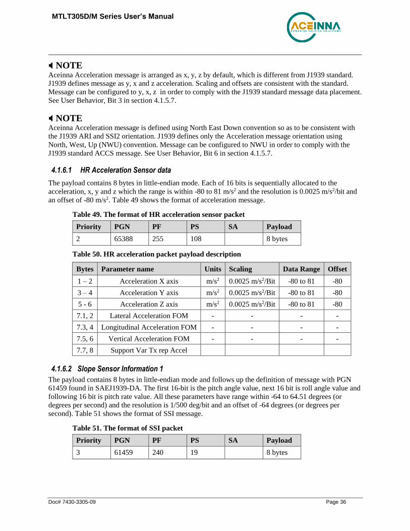
MTLT305D/M Series User’s Manual
_____________________________________________________________________________________
Doc# 7430-3305-09 Page 36
NOTE Aceinna Acceleration message is arranged as x, y, z by default, which is different from J1939 standard.
J1939 defines message as y, x and z acceleration. Scaling and offsets are consistent with the standard.
Message can be configured to y, x, z in order to comply with the J1939 standard message data placement.
See User Behavior, Bit 3 in section 4.1.5.7.
NOTE Aceinna Acceleration message is defined using North East Down convention so as to be consistent with
the J1939 ARI and SSI2 orientation. J1939 defines only the Acceleration message orientation using
North, West, Up (NWU) convention. Message can be configured to NWU in order to comply with the
J1939 standard ACCS message. See User Behavior, Bit 6 in section 4.1.5.7.
4.1.6.1 HR Acceleration Sensor data
The payload contains 8 bytes in little-endian mode. Each of 16 bits is sequentially allocated to the
acceleration, x, y and z which the range is within -80 to 81 m/s2 and the resolution is 0.0025 m/s2/bit and
an offset of -80 m/s2. Table 49 shows the format of acceleration message.
Table 49. The format of HR acceleration sensor packet
Priority PGN PF PS SA Payload
2 65388 255 108 8 bytes
Table 50. HR acceleration packet payload description
Bytes Parameter name Units Scaling Data Range Offset
1 – 2 Acceleration X axis m/s2 0.0025 m/s2/Bit -80 to 81 -80
3 – 4 Acceleration Y axis m/s2 0.0025 m/s2/Bit -80 to 81 -80
5 - 6 Acceleration Z axis m/s2 0.0025 m/s2/Bit -80 to 81 -80
7.1, 2 Lateral Acceleration FOM - - - -
7.3, 4 Longitudinal Acceleration FOM - - - -
7.5, 6 Vertical Acceleration FOM - - - -
7.7, 8 Support Var Tx rep Accel
4.1.6.2 Slope Sensor Information 1
The payload contains 8 bytes in little-endian mode and follows up the definition of message with PGN
61459 found in SAEJ1939-DA. The first 16-bit is the pitch angle value, next 16 bit is roll angle value and
following 16 bit is pitch rate value. All these parameters have range within -64 to 64.51 degrees (or
degrees per second) and the resolution is 1/500 deg/bit and an offset of -64 degrees (or degrees per
second). Table 51 shows the format of SSI message.
Table 51. The format of SSI packet
Priority PGN PF PS SA Payload
3 61459 240 19 8 bytes

MTLT305D/M Series User’s Manual
_____________________________________________________________________________________
Doc# 7430-3305-09 Page 37
Table 52. SSI packet payload description
Bytes Parameter name Units Scaling Data Range Offset
1 – 2 Pitch Angle ° 0.002° -64 to 64.51 -64
3 – 4 Roll Angle ° 0.002 °/s -64 to 64.51 -64
5 - 6 Pitch Rate ° 0.002 °/s -64 to 64.51 -64
7.1,2 Pitch Angle FOM - - - -
7.3,4 Roll Angle FOM - - - -
7.5,6 Pitch Rate FOM - - - -
7.7,8 Pitch and Roll Comp - - - -
8 Roll and Pitch Latency ms/bit 0.5ms/bit 0 to 125 0
DBC File
A DBC file is a proprietary but common descriptor database file that is used to describes the CAN
network and message decoding. DBC files are created and administered with either the CANdb editor or
the CANdb++ editor available from Vector.
The format of DBC file follows the definition of Vector DBC Standard. The link is
https://vector.com/vi_candb_en.html
A simplified description of DBC file is available on
https://github.com/stefanhoelzl/CANpy/tree/master/docs. However, users must contact Vector if the full
syntax of DBC file is desired.
A DBC file supporting ACEINNA MTLT305D/M is available for download from ACEINNA website
from the MTLT305D/M Product page. https://www.aceinna.com/inertial-systems/MTLT305D

MTLT305D/M Series User’s Manual
_____________________________________________________________________________________
Doc# 7430-3305-09 Page 38
RS232 Port Interface Definition
The MTLT305D/M Series support a common packet structure that includes both command or input data
packets (data sent to the MTLT305D/M Series) and measurement output or response packet formats (data
sent from the MTLT305D/M Series). This section of the manual explains these packet formats as well as
the supported commands. NAV-VIEW also features a number of tools that can help a user understand the
packet types available and the information contained within the packets. This section of the manual
assumes that the user is familiar with ANSI C programming language and data type conventions.
For an example of code required to parse input data packets, please see refer to Appendix B: Sample
RS232 Packet-Parser Code
For qualified commercial OEM users, a source code license of NAV-VIEW can be made available under
certain conditions. Please contact your ACEINNA representative for more information.
General Settings
The serial port settings are RS232 with 1 start bit, 8 data bits, no parity bit, 1 stop bit, and no flow control.
Standard baud rates supported are 38400, 57600, 115200, and 230400.
Common definitions include:
• A word is defined to be 2 bytes or 16 bits.
• All communications to and from the unit are packets that start with a single word alternating bit
preamble 0x5555. This is the ASCII string “UU”.
• All multiple byte values are transmitted Big Endian (Most Significant Byte First).
• All communication packets end with a single word CRC (2 bytes). CRC’s are calculated on all
packet bytes excluding the preamble and CRC itself. Input packets with incorrect CRC’s will be
ignored.
• Each complete communication packet must be transmitted to the MTLT305D/M Series inertial
system within a 4 second period.
Number Formats
Number Format Conventions include:
• 0x as a prefix to hexadecimal values
• single quotes (‘’) to delimit ASCII characters
• no prefix or delimiters to specify decimal values.

MTLT305D/M Series User’s Manual
_____________________________________________________________________________________
Doc# 7430-3305-09 Page 39
Table 53 defines number formats:
Table 53 Number Formats
Descriptor Description Size
(bytes)
Comment Range
U1 Unsigned Char 1 0 to 255
U2 Unsigned Short 2 0 to 65535
U4 Unsigned Int 4 0 to 2^32-1
I2 Signed Short 2 2’s Complement -2^15 to 2^15-1
I2* Signed Short 2 Shifted 2’s
Complement
Shifted to
specified range
I4 Signed Int 4 2’s Complement -2^31 to 2^31-1
F4 Floating Point 4 IEEE754 Single
Precision
-1*2^127 to 2^127
SN String N ASCII
Packet Format
All of the Input and Output packets, except the Ping command, conform to the following structure:
0x5555 <2-byte packet
type (U2)>
<payload byte-
length (U1)>
<variable length
payload>
<2-byte CRC
(U2)>
The Ping Command does not require a CRC, so a MTLT305D/M Series unit can be pinged from a
terminal emulator. To Ping a MTLT305D/M Series unit, type the ASCII string ‘UUPK’. If properly
connected, the MTLT305D/M Series unit will respond with ‘PK’. All other communications with the
MTLT305D/M Series unit require the 2-byte CRC. {Note: A MTLT305D/M Series unit will also respond
to a ping command using the full packet formation with payload 0 and correctly calculated CRC.
Example: 0x5555504B009ef4 }.
Packet Header
The packet header is always the bit pattern 0x5555.
Packet Type
The packet type is always two bytes long in unsigned short integer format. Most input and output packet
types can be interpreted as a pair of ASCII characters. As a semantic aid consider the following single
character acronyms:
P = packet
F = fields
Refers to Fields which are settings or data contained in the unit
E = EEPROM
Refers to factory data stored in EEPROM
R = read

MTLT305D/M Series User’s Manual
_____________________________________________________________________________________
Doc# 7430-3305-09 Page 40
Reads default non-volatile fields
G = get
Gets current volatile fields or settings
W = write
Writes default non-volatile fields. These fields are stored in non-volatile memory and determine
the unit’s behavior on power up. Modifying default fields take effect on the next power up and
thereafter.
S = set
Sets current volatile fields or settings. Modifying current fields will take effect immediately by
modifying internal RAM and are lost on a power cycle
Payload Length
The payload length is always a one byte unsigned character with a range of 0-255. The payload length
byte is the length (in bytes) of the <variable length payload> portion of the packet ONLY, and does not
include the CRC.
Payload
The payload is of variable length based on the packet type.
16-bit CRC-CCITT
Packets end with a 16-bit CRC-CCITT calculated on the entire packet excluding the 0x5555 header and
the CRC field itself. A discussion of the 16-bit CRC-CCITT and sample code for implementing the
computation of the CRC is included at the end of this document. This 16-bit CRC standard is maintained
by the International Telecommunication Union (ITU). The highlights are:
Width = 16 bits
Polynomial 0x1021
Initial value = 0xFFFF
No XOR performed on the final value.
See Appendix D for sample code that implements the 16-bit CRC algorithm.
Messaging Overview
Table 54 summarizes the messages available by MTLT305D/M Series model. Packet types are assigned
mostly using the ASCII mnemonics defined above and are indicated in the summary Table 54 and in the
detailed sections for each command. The payload byte-length is often related to other data elements in the
packet as defined in the table below. The referenced variables are defined in the detailed sections
following. Output messages are sent from the MTLT305D/M Series inertial system to the user system as
a result of a poll request or a continuous packet output setting. Input messages are sent from the user
system to the MTLT305D/M Series inertial system and will result in an associated Reply Message or
NAK message. Note that reply messages typically have the same <2-byte packet type (U2)> as the input
message that evoked it but with a different payload.

MTLT305D/M Series User’s Manual
_____________________________________________________________________________________
Doc# 7430-3305-09 Page 41
Table 54 Message Table
ASCII
Mnemonic
<2-byte
packet type
(U2)>
<payload byte-
length (U1)>
Description Type
Link Test
PK 0x504B 0 Ping Command and
Response
Input/Reply Message
CH 0x4348 N Echo Command and
Response
Input/Reply Message
Interactive Commands
GP 0x4750 2 Get Packet Request Input Message
AR 0x4152 0 Algorithm Reset Input/Reply Message
NAK 0x1515 2 Error Response Reply Message
Output Messages: Status & Other, (Polled Only)
ID 0x4944 5+N Identification Data Output Message
VR 0x5652 5 Version Data Output Message
T0 0x5430 28 Test 0 (Detailed BIT
and Status)
Output Message
Output Messages: Measurement Data
(Continuous or Polled)
A2 0x4132 30 Angle 2 Data Output Message
Advanced Commands
WF 0x5746 numFields*4+1 Write Fields Request Input Message
WF 0x5746 numFields*2+1 Write Fields Response Reply Message
SF 0x5346 numFields*4+1 Set Fields Request Input Message
SF 0x5346 numFields*2+1 Set Fields Response Reply Message
RF 0x5246 numFields*2+1 Read Fields Request Input Message
RF 0x5246 numFields*4+1 Read Fields Response Reply Message
GF 0x4746 numFields*2+1 Get Fields Request Input Message
GF 0x4746 numFields*4+1 Get Fields Response Reply Message

MTLT305D/M Series User’s Manual
_____________________________________________________________________________________
Doc# 7430-3305-09 Page 42
MTLT305D/M Standard RS232 Port Commands and Messages
Link Test.
Ping Command
Ping (‘PK’ = 0x504B)
Preamble Packet Type Length Termination
0x5555 0x504B - -
The ping command has no payload. Sending the ping command will cause the unit to send a ping
response. To facilitate human input from a terminal, the length and CRC fields are not required.
(Example: 0x5555504B009ef4 or 0x5555504B))
Ping Response
Ping (‘PK’ = 0x504B)
Preamble Packet Type Length Termination
0x5555 0x504B 0x00 <CRC (U2)>
The unit will send this packet in response to a ping command.
Echo Command
Echo (‘CH’ = 0x4348)
Preamble Packet Type Length Payload Termination
0x5555 0x4348 N <echo payload> <CRC (U2)>
The echo command allows testing and verification of the communication link. The unit will respond with
an echo response containing the echo data. The echo data is N bytes long.
Echo Response
Echo Payload Contents
Byte
Offset
Name Format Scaling Units Description
0 echoData0 U1 - - first byte of echo data
1 echoData1 U1 - - Second byte of echo data
… … U1 - - Echo data
N-2 echoData... U1 - - Second to last byte of echo data
N-1 echoData… U1 - - Last byte of echo data
Interactive Commands
Interactive commands are used to interactively request data from the MTLT305D/M Series, and to
calibrate or reset the MTLT305D/M Series.

MTLT305D/M Series User’s Manual
_____________________________________________________________________________________
Doc# 7430-3305-09 Page 43
Get Packet Request
Get Packet (‘GP’ = 0x4750)
Preamble Packet Type Length Payload Termination
0x5555 0x4750 0x02 <GP payload> <CRC (U2)>
This command allows the user to poll for both measurement packets and special purpose output packets
including ‘T0’, ‘VR’, and ‘ID’.
GP Payload Contents
Byte
Offset
Name Format Description
0 requestedPacketType U2 The requested packet type
Refer to the sections below for Packet Definitions sent in response to the ‘GP’ command
Algorithm Reset Command
Algorithm Reset (‘AR’ = 0x4152)
Preamble Packet Type Length Payload Termination
0x5555 0x4152 0x00 - <CRC (U2)>
This command resets the state estimation algorithm without reloading fields from EEPROM. All current
field values will remain in effect. The unit will respond with an algorithm reset response.
Algorithm Reset Response
Algorithm Reset (‘AR’ = 0x4152)
Preamble Packet Type Length Termination
0x5555 0x4152 0x00 <CRC (U2)>
The unit will send this packet in response to an algorithm reset command.
Error Response
Error Response (ASCII NAK, NAK = 0x1515)
Preamble Packet Type Length Payload Termination
0x5555 0x1515 0x02 <NAK payload> <CRC (U2)>
Alternative Response
Preamble Packet Type Length Payload Termination
0x5555 0x0000 0x02 <NAK payload> <CRC (U2)>
The unit will send this packet in place of a normal response to a failedInputPacketType request if it could
not be completed successfully.

MTLT305D/M Series User’s Manual
_____________________________________________________________________________________
Doc# 7430-3305-09 Page 44
NAK Payload Contents
Byte
Offset
Name Format Description
0 failedInputPacketType U2 the failed request or 0x0000
Output Packets (Polled)
The following packet formats are special informational packets which can be requested using the ‘GP’
command.
Identification Data Packet
Identification Data (‘ID’ = 0x4944)
Preamble Packet Type Length Payload Termination
0x5555 0x4944 5+N <ID payload> <CRC (U2)>
This packet contains the unit serialNumber and modelString. The model string is terminated
with 0x00. The model string contains the programmed versionString (8-bit Ascii values)
followed by the firmware part number string delimited by a whitespace. ID Payload
Contents
Byte Offset Name Format Scaling Units Description
0 serialNumber U4 - - Unit serial number
4 modelString SN - - Unit Version String
4+N 0x00 U1 - - Zero Delimiter
Version Data Packet
Version Data (‘VR’ = 0x5652)
Preamble Packet Type Length Payload Termination
0x5555 0x5652 5 <VR payload> <CRC (U2)>
This packet contains firmware version information. majorVersion changes may introduce serious
incompatibilities. minorVersion changes may add or modify functionality, but maintain backward
compatibility with previous minor versions. patch level changes reflect bug fixes and internal
modifications with little effect on the user. The build stage is one of the following: 0=release candidate,
1=development, 2=alpha, 3=beta. The buildNumber is incremented with each engineering firmware build.
The buildNumber and stage for released firmware are both zero. The final beta candidate is v.w.x.3.y,
which is then changed to v.w.x.0.1 to create the first release candidate. The last release candidate is
v.w.x.0.z, which is then changed to v.w.x.0.0 for release.
VR Payload Contents
Byte Offset Name Format Description
0 majorVersion U1 Major firmware version
1 minorVersion U1 Minor firmware version
2 patch U1 Patch level

MTLT305D/M Series User’s Manual
_____________________________________________________________________________________
Doc# 7430-3305-09 Page 45
VR Payload Contents
Byte Offset Name Format Description
3 stage - Development Stage (0=release candidate,
1=development, 2=alpha, 3=beta)
4 buildNumber U1 Build number
Test 0 (Detailed BIT and Status) Packet
Test (‘T0’ = 0x5430)
Preamble Packet Type Length Payload Termination
03.3x5555 0x5430 0x1C <T0 payload> <CRC (U2)>
This packet contains detailed BIT and status information. The full BIT Status details are described in
Appendix D: Advanced RS232 Port BIT.
Table 55. T0 Payload Contents
T0 Payload Contents
Byte
Offset
Name Format Description
0 BITstatus U2 Master BIT and Status Field
2 hardwareBIT U2 Hardware BIT Field
4 hardwarePowerBIT U2 Hardware Power BIT Field
6 hardwareEnvironmentalBIT U2 Hardware Environmental BIT Field
8 comBIT U2 communication BIT Field
10 comSerialABIT U2 Communication Serial A BIT Field
12 comSerialBBIT U2 Communication Serial B BIT Field
14 softwareBIT U2 Software BIT Field
16 softwareAlgorithmBIT U2 Software Algorithm BIT Field
18 softwareDataBIT U2 Software Data BIT Field
20 hardwareStatus U2 Hardware Status Field
22 comStatus U2 Communication Status Field
24 softwareStatus U2 Software Status Field
26 sensorStatus U2 Sensor Status Field
RS232 Output Packets (Polled or Continuous)
Angle Data Packet 2 (Default MTLT305D/M Data)
Angle Data (‘A2’ = 0x4132)
Preamble Packet Type Length Payload Termination
0x5555 0x4132 0x1E <A2 payload> <CRC (U2)>
This packet contains angle data and selected sensor data scaled in most cases to a signed 2^16 2’s
complement number. Data involving angular measurements include the factor pi in the scaling and can be
interpreted in either radians or degrees.

MTLT305D/M Series User’s Manual
_____________________________________________________________________________________
Doc# 7430-3305-09 Page 46
Angles: scaled to a range of [-pi,+pi) or [-180 deg to +180 deg).
Angular rates: scaled to range of 3.5* [-pi,+pi) or [-630 deg/sec to +630 deg/sec)
Accelerometers: scaled to a range of [-10,+10) g
Temperature: scaled to a range of [-100, +100) °C
A2 Payload Contents
Byte
Offset
Name Format Scaling Units Description
0 rollAngle I2 2*pi/2^16
[360°/2^16]
Radians
[°]
Roll angle
2 pitchAngle I2 2*pi/2^16
[360°/2^16]
Radians
[°]
Pitch angle
4 yawAngleTrue I2 2*pi/2^16
[360°/2^16]
Radians
[°]
Yaw angle (free)
6 xRateCorrected I2 7*pi/2^16
[1260°/2^16]
rad/s
[°/sec]
X angular rate corrected
8 yRateCorrected I2 7*pi/2^16
[1260°/2^16]
rad/s
[°/sec]
Y angular rate corrected
10 zRateCorrected I2 7*pi/2^16
[1260°/2^16]
rad/s
[°/sec]
Z angular rate corrected
12 xAccel I2 20/2^16 G X accelerometer
14 yAccel I2 20/2^16 G Y accelerometer
16 zAccel I2 20/2^16 G Z accelerometer
18 xRateTemp I2 200/2^16 deg. C X rate temperature
20 yRateTemp I2 200/2^16 deg. C Y rate temperature
22 zRateTemp I2 200/2^16 deg. C Z rate temperature
24 timeITOW U4 1 ms Not Implemented
DMU ITOW (sync to GPS)
28 BITstatus U2 - - Master BIT and Status

MTLT305D/M Series User’s Manual
_____________________________________________________________________________________
Doc# 7430-3305-09 Page 47
MTLT305D/M Advanced RS232 Port Commands
Configuration Fields
Configuration fields determine various behaviors of the unit that can be modified by the user. These
include settings like baud rate, packet output The advanced commands allow users to programmatically
change the MTLT305D/M Series settings. This section of the manual documents all of the settings and
options contained under the Unit Configuration tab within NAV-VIEW. Using these advanced
commands, a user’s system can change or modify the settings without the need for NAVrate and type,
algorithm type, etc. These fields are stored in EEPROM and loaded on power up. These fields can be read
from the EEPROM using the ‘RF’ command. These fields can be written to the EEPROM affecting the
default power up behavior using the ‘WF’ command. The current value of these fields (which may be
different from the value stored in the EEPROM) can also be accessed using the ‘GF’ command. All of
these fields can also be modified immediately for the duration of the current power cycle using the ‘SF’
command. The unit will always power up in the configuration stored in the EEPROM. Configuration
fields can only be set or written with valid data from Table 56 below.
Table 56 Configuration Fields
configuration fields field ID Valid Values description
Packet rate divider 0x0001
0,1,2,4,5,10, 20, 25,
50
quiet, 100Hz, 50Hz, 25Hz, 20Hz,
10Hz, 5Hz, 4Hz 2Hz
Unit BAUD rate 0x0002 2,3,5,6 38400, 57600, 115200, 230400
Continuous packet type 0x0003
Any output packet
type
Not all output packets available for all
products. See detailed product
descriptions.
Unused 0x0004
Accelerometer Filter
Setting 0x0005
18750-65535 [2Hz]
8035-18749 [5Hz]
4018-8034 [10Hz]
2411-4017 [20Hz]
1741-2410 [25Hz]
1205-1740 [40Hz]
1-1204 [50 Hz]
0 [Unfiltered]
Sets low pass cutoff for accelerometers.
Cutoff Frequency choices are 2, 5, 10,
20, 25, 40, and 50Hz
Gyro Filter Setting 0x0006
18750-65535 [2Hz]
8035-18749 [5Hz]
4018-8034 [10Hz]
2411-4017 [20Hz]
1741-2410 [25Hz]
1205-1740 [40Hz]
1-1204 [50 Hz]
0 [Unfiltered]
Sets low pass cutoff for rate sensors.
Cutoff Frequency choices are 2, 5, 10,
20, 25, 40, and 50Hz
Orientation 0x0007 See below
Determine forward, rightward, and
downward facing sides
User Behavior Switch 0x0008 See below

MTLT305D/M Series User’s Manual
_____________________________________________________________________________________
Doc# 7430-3305-09 Page 48
Rate Integration Time
Limit 0x003E 0.01 - 10000 In milliseconds, default 2000
Linear Acceleration Switch
Delay Limit 0x003F 0.01 - 10000 In milliseconds, default 2000
Coefficient of reduced Q 0x0040 1 – 10000 0.0001 per lsb, default 10
Note: BAUD rate SF has immediate effect. Some output data may be lost. Response will be received at
new BAUD rate.
Continuous Packet Type Field
This is the packet type that is being continually output. The supported packet depends on the model
number. Please refer to Section 6.4 for a complete list of the available packet types.
Digital Filter Settings
These two fields set the digital low pass filter cutoff frequencies ( See Table 57). Each sensor listed is
defined in the default factory orientation. Users must consider any additional rotation to their intended
orientation.
Table 57 Digital Filter Settings
Filter Setting Sensor
FilterGyro Ux,Uy,Uz Rate
FilterAccel Ux,Uy,Uz Acceleration
Orientation Field
This field defines the rotation from the factory to user axis sets. This rotation is relative to the default
factory orientation for the MTLT305D/M family model. The default factory axis setting for the
MTLT305D/M orientation field is (+Ux +Uy, +Uz) which defines the connector pointing to the opposite
of +X direction and +Z direction going out the bottom of the unit. See Figure .
Table 58. MTLT305D/M Orientation Definitions
Description Bits Meaning
X Axis Sign 0 0 = positive, 1 = negative
X Axis 1:2 0 = Ux, 1 = Uy, 2 = Uz, 3 = N/A
Y Axis Sign 3 0 = positive, 1 = negative
Y Axis 4:5 0 = Uy, 1 = Uz, 2 = Ux, 3 = N/A
Z Axis Sign 6 0 = positive, 1 = negative
Z Axis 7:8 0 = Uz, 1 = Ux, 2 = Uy, 3 = N/A
Reserved 9:15 N/A
There are 24 possible orientation configurations (See Table 59) Setting/Writing the field to anything else
generates a NAK and has no effect.

MTLT305D/M Series User’s Manual
_____________________________________________________________________________________
Doc# 7430-3305-09 Page 49
Table 59. MTLT305D/M Orientation Fields
Orientation Field Value X Axis Y Axis Z Axis
0x0000 +Ux +Uy +Uz
0x0009 -Ux -Uy +Uz
0x0023 -Uy +Ux +Uz
0x002A +Uy -Ux +Uz
0x0041 -Ux +Uy -Uz
0x0048 +Ux -Uy -Uz
0x0062 +Uy +Ux -Uz
0x006B -Uy -Ux -Uz
0x0085 -Uz +Uy +Ux
0x008C +Uz -Uy +Ux
0x0092 +Uy +Uz +Ux
0x009B -Uy -Uz +Ux
0x00C4 +Uz +Uy -Ux
0x00CD -Uz -Uy -Ux
0x00D3 -Uy +Uz -Ux
0x00DA +Uy -Uz -Ux
0x0111 -Ux +Uz +Uy
0x0118 +Ux -Uz +Uy
0x0124 +Uz +Ux +Uy
0x012D -Uz -Ux +Uy
0x0150 +Ux +Uz -Uy
0x0159 -Ux -Uz -Uy
0x0165 -Uz +Ux -Uy
0x016C +Uz -Ux -Uy

MTLT305D/M Series User’s Manual
_____________________________________________________________________________________
Doc# 7430-3305-09 Page 50
User Behavior Switches
This field allows on the fly user interaction with behavioral aspects of the algorithm ( See Table 60 ).
Table 60 MTLT305D/M Behavior Switches
Description Bits Meaning
Free Integrate 0 0 = use feedback to stabilize the algorithm
1 = 6DOF inertial integration without stabilized
feedback for 60 seconds
Default = 0
Reserved 1 N/A
Reserved 2 N/A
Reserved 3 N/A
Restart on Over-range 4 0 = Do not restart the system after a sensor over-
range, 1 = restart the system after a sensor over-range
Default = 0
Dynamic Motion 5 Reserved
Use Raw Rates 6 1 – Use raw rates instead of corrected rates in CAN
ARI message
Default = 0
Swap Pitch And Roll 7 1 - Swap Pitch And Roll in axes in CAN acceleration
and angular rates messages
Default = 0
Use NWU or NED Frame
in CAN ACCS message
8 1 – Use NWU frame, 0 – use NED frame
Default = 0
Use Raw or Filtered
Accelerometer data to
detect linear acceleration
9 1 – use raw data, 0 – use filtered data
Default = 1
Use Raw or Corrected rate
in linear acceleration
detection logic
10 1 – use raw data, 0 – use corrected data
Default 0
Reserved 11:15 N/A

MTLT305D/M Series User’s Manual
_____________________________________________________________________________________
Doc# 7430-3305-09 Page 51
Commands to Program Configuration Over RS232
Write Fields Command
Write Fields (‘WF’ = 0x5746)
Preamble Packet Type Length Payload Termination
0x5555 0x5746 1+numFields*4 <WF payload> <CRC
(U2)>
This command allows the user to write default power-up configuration fields to the EEPROM. Writing
the default configuration will not take effect until the unit is power cycled. NumFields is the number of
words to be written. The field0, field1, etc. are the field
IDs that will be written with the field0Data, field1Data, etc., respectively. The unit will not write to
calibration or algorithm fields. If at least one field is successfully written, the unit will respond with a
write fields response containing the field IDs of the successfully written fields. If any field is unable to be
written, the unit will respond with an error response. Note that both a write fields and an error response
may be received as a result of a write fields command. Attempts to write a field with an invalid value is
one way to generate an error response. A table of field IDs and valid field values is available in Section
7.1.
WF Payload Contents
Byte Offset Name Format Scaling Units Description
0 numFields U1 - - The number of fields to write
1 field0 U2 - - The first field ID to write
3 field0Data U2 - - The first field ID’s data to write
5 field1 U2 - - The second field ID to write
7 field1Data U2 - - The second field ID’s data
… … U2 - - …
numFields*4 -3 field… U2 - - The last field ID to write
numFields*4 -1 field…Data U2 - - The last field ID’s data to write
Write Fields Response
Write Fields (‘WF’ = 0x5746)
Preamble Packet Type Length Payload Termination
0x5555 0x5746 1+numFields*2 <WF payload> <CRC
(U2)>
The unit will send this packet in response to a write fields command if the command has completed
without errors.
WF Payload Contents
Byte Offset Name Format Scaling Units Description
0 numFields U1 - - The number of fields written
1 field0 U2 - - The first field ID written
3 field1 U2 - - The second field ID written

MTLT305D/M Series User’s Manual
_____________________________________________________________________________________
Doc# 7430-3305-09 Page 52
… … U2 - - More field IDs written
numFields*2
– 1
Field… U2 - - The last field ID written
Set Fields Command
Set Fields (‘SF’ = 0x5346)
Preamble Packet Type Length Payload Termination
0x5555 0x5346 1+numFields*4 <SF payload>
<CRC
(U2)>
This command allows the user to set the unit’s current configuration (SF) fields immediately which will
then be lost on power down. NumFields is the number of words to be set. The field0, field1, etc. are the
field IDs that will be written with the field0Data, field1Data, etc., respectively. This command can be
used to set configuration fields. The unit will not set calibration or algorithm fields. If at least one field is
successfully set, the unit will respond with a set fields response containing the field IDs of the
successfully set fields. If any field is unable to be set, the unit will respond with an error response. Note
that both a set fields and an error response may be received as a result of one set fields command.
Attempts to set a field with an invalid value is one way to generate an error response. A table of field IDs
and valid field values is available in Section 7.1.
SF Payload Contents
Byte Offset Name Format Scaling Units Description
0 numFields U1 - - The number of fields to set
1 field0 U2 - - The first field ID to set
3 field0Data U2 - - The first field ID’s data to set
5 field1 U2 - - The second field ID to set
7 field1Data U2 - - The second field ID’s data to set
… … U2 - - …
numFields*4 -3 field… U2 - - The last field ID to set
numFields*4 -1 field…Data U2 - - The last field ID’s data to set
Set Fields Response
Set Fields (‘SF’ = 0x5346)
Preamble Packet Type Length Payload Termination
0x5555 0x5346 1+numFields*2 <SF payload>
<CRC
(U2)>
The unit will send this packet in response to a set fields command if the command has completed without
errors.

MTLT305D/M Series User’s Manual
_____________________________________________________________________________________
Doc# 7430-3305-09 Page 53
SF Payload Contents
Byte Offset Name Format Description
0 numFields U1 The number of fields to set
1 field0 U2 The first field ID to set
3 field1 U2 The second field ID to set
… … U2 More field IDs to set
numFields*2 - 1 Field… U2 The last field ID to set
Read Fields Command
Read Fields (‘RF’ = 0x5246)
Preamble Packet Type Length Payload Termination
0x5555 0x5246 1+numFields*2 <RF payload>
<CRC
(U2)>
This command allows the user to read the default power-up configuration fields from the EEPROM.
NumFields is the number of fields to read. The field0, field1, etc. are the field IDs to read. RF may be
used to read configuration and calibration fields from the EEPROM. If at least one field is successfully
read, the unit will respond with a read fields response containing the field IDs and data from the
successfully read fields. If any field is unable to be read, the unit will respond with an error response.
Note that both a read fields and an error response may be received as a result of a read fields command.
RF Payload Contents
Byte Offset Name Format Description
0 numFields U1 The number of fields to read
1 field0 U2 The first field ID to read
3 field1 U2 The second field ID to read
… … U2 More field IDs to read
numFields*2 - 1 Field… U2 The last field ID to read
Read Fields Response
Read Fields (‘RF’ = 0x5246)
Preamble Packet Type Length Payload Termination
0x5555 0x5246 1+numFields*4 <RF payload> <CRC (U2)>
The unit will send this packet in response to a read fields request if the command has completed without
errors.

MTLT305D/M Series User’s Manual
_____________________________________________________________________________________
Doc# 7430-3305-09 Page 54
RF Payload Contents
Byte Offset Name Format Scaling Units Description
0 numFields U1 - - The number of fields read
1 field0 U2 - - The first field ID read
3 field0Data U2 - - The first field ID’s data read
5 field1 U2 - - The second field ID read
7 field1Data U2 - - The second field ID’s data read
… … U2 - - …
numFields*4 -3 field… U2 - - The last field ID read
numFields*4 -1 field…Data U2 - - The last field ID’s data read
Get Fields Command
Get Fields (‘GF’ = 0x4746)
Preamble Packet Type Length Payload Termination
0x5555 0x4746 1+numFields*2 <GF Data>
<CRC
(U2)>
This command allows the user to get the unit’s current configuration fields. NumFields is the number of
fields to get. The field0, field1, etc. are the field IDs to get. GF may be used to get configuration,
calibration, and algorithm fields from RAM. Multiple algorithm fields will not necessarily be from the
same algorithm iteration. If at least one field is successfully collected, the unit will respond with a get
fields response with data containing the field IDs of the successfully received fields. If any field is unable
to be received, the unit will respond with an error response. Note that both a get fields and an error
response may be received as the result of a get fields command.
GF Payload Contents
Byte Offset Name Format Scaling Units Description
0 numFields U1 - - The number of fields to get
1 field0 U2 - - The first field ID to get
3 field1 U2 - - The second field ID to get
… … U2 - - More field IDs to get
numFields*2 –
1
Field… U2 - - The last field ID to get
Get Fields Response
Get Fields (‘GF’ = 0x4746)
Preamble Packet Type Length Payload Termination
0x5555 0x4746 1+numFields*4 <GF Data> <CRC (U2)>
The unit will send this packet in response to a get fields request if the command has completed without
errors.

MTLT305D/M Series User’s Manual
_____________________________________________________________________________________
Doc# 7430-3305-09 Page 55
GF Payload Contents
Byte Offset Name Format Scaling Units Description
0 numFields U1 - - The number of fields retrieved
1 field0 U2 - - The first field ID retrieved
3 field0Data U2 - - The first field ID’s data
retrieved
5 field1 U2 - - The second field ID retrieved
7 field1Data U2 - - The second field ID’s data
… … U2 - - …
numFields*4 -3 field… U2 - - The last field ID retrieved
numFields*4 -1 field…Data U2 - - The last field ID’s data
retrieved

MTLT305D/M Series User’s Manual
_____________________________________________________________________________________
Doc# 7430-3305-09 Page 56
Bootloader
Bootloader Initialization
A user can initiate Bootloader at any time by sending ‘JI’ command (see below command’s format) to
application program. This command forces the unit enter Bootloader mode. The unit will communicate at
57.6kb/s baud rate regardless of the original baud rate the unit is configured to. The Bootloader always
communicates at 57.6kb/s until the firmware upgrade is complete.
As an additional device recovery option immediately after powering up, every MTLT3xD will enter a
recovery window of 100ms prior to application start. During this 100mS window, the user can send ‘JI’
command at 57.6kb/s to the Bootloader in order to force the unit to remain in Bootloader mode.
Once the device enters Bootloader mode via the ‘JI’ command either during recovery window or from
normal operation, a user can send a sequence ‘WA’ commands to write a complete application image into
the device’s FLASH.
After loading the entire firmware image with successive ‘WA’ commands, a ‘JA’ command is sent to
instruct the unit to exit Bootloader mode and begin application execution. At this point, the device will
return to its original baud rate.
Optionally, the system can be reboot by cycling power to restart the system.
Firmware Upgrade Command
The commands detailed in Sections 8.2.1 are used for upgrading a new firmware version.
UART Interface
Firmware upgrade is performed by a Write APP command through UART port, through Windows GUI,
NAV-View, or a python program. See Appendix A: Installation and Operation of NAV-VIEW over
RS232
The following commands allow users to install a pre-built binary into flash memory and force system to
enter either Bootloader or application mode.
8.2.1.1 Jump to Bootloader Command
Jump To Bootloader (‘JI’ = 0x4A49)
Preamble Packet Type Length Payload Termination
0x5555 0x4A49 0x00
CRC (U2)
The command allows system to enter Bootloader mode.
8.2.1.2 Write APP Command
Write APP (“WA” = 0x5741)
Preamble Packet Type Length Payload Termination
0x5555 0x5741 length+5 CRC (U2)
The command allows users to write binary sequentially to flash memory in Bootloader mode. The total
length is the sum of payload’s length and 4-byte address followed by 1-byte data length. See the
following table of the payload’s format.

MTLT305D/M Series User’s Manual
_____________________________________________________________________________________
Doc# 7430-3305-09 Page 57
WA Payload Contents
Byte Offset Name Format Scaling Units Description
0 startingAddress U4 - bytes The FLASH word offset to
begin writing data
4 byteLength U1 - bytes The word length of the data
to write
5 dataByte0 U1 - - FLASH data
6 dataByte1 U1 - - FLASH data
… …
4+byteLength dataByte U1 - - FLASH data
Payload starts from 4-byte address of flash memory where the binary is located. The fifth byte is the
number of bytes of dataBytess, but less than 240 bytes. User must truncate the binary to less than 240-
byte blocks and fill each of blocks into payload starting from the sixth-byte.
8.2.1.3 Jump to Application Command
Jump To Application (‘JA’ = 0x4A41)
Preamble Packet Type Length Payload Termination
0x5555 0x4A41 0x00
CRC (U2)
The command allows system directly to enter application mode.

MTLT305D/M Series User’s Manual
_____________________________________________________________________________________
Doc# 7430-3305-09 Page 58
Warranty and Support Information
Customer Service
As a ACEINNA customer you have access to product support services, which include:
• Single-point return service
• Web-based support service
• Same day troubleshooting assistance
• Worldwide ACEINNA representation
• Onsite and factory training available
• Preventative maintenance and repair programs
• Installation assistance available
Contact Directory
Email: [email protected]
http://www.aceinna.com/support/index.cfm
Return Procedure
Authorization
Before returning any equipment, please contact ACEINNA to obtain a Returned Material Authorization
number (RMA).
Be ready to provide the following information when requesting a RMA:
• Name
• Address
• Telephone, Fax, Email
• Equipment Model Number
• Equipment Serial Number
• Installation Date
• Failure Date
• Fault Description
• Will it connect to NAV-VIEW 3.X?
Identification and Protection
If the equipment is to be shipped to ACEINNA for service or repair, please attach a tag TO THE
EQUIPMENT, as well as the shipping container(s), identifying the owner. Also indicate the service or
repair required, the problems encountered, and other information considered valuable to the service
facility such as the list of information provided to request the RMA number.
Place the equipment in the original shipping container(s), making sure there is adequate packing around
all sides of the equipment. If the original shipping containers were discarded, use heavy boxes with
adequate padding and protection.

MTLT305D/M Series User’s Manual
_____________________________________________________________________________________
Doc# 7430-3305-09 Page 59
Sealing the Container
Seal the shipping container(s) with heavy tape or metal bands strong enough to handle the weight of the
equipment and the container.
Marking
Please write the words, “FRAGILE, DELICATE INSTRUMENT” in several places on the outside of the
shipping container(s). In all correspondence, please refer to the equipment by the model number, the
serial number, and the RMA number.
Warranty
The ACEINNA product warranty is one year from date of shipment.

MTLT305D/M Series User’s Manual
_____________________________________________________________________________________
Doc# 7430-3305-09 Page 60
Appendix A: Installation and Operation of NAV-VIEW over RS232
NAV-VIEW has been designed to allow users to control all aspects of the MTLT305D/M Series
operation including data recording, configuration and data transfer. For the first time, you will be able to
control the orientation of the unit, sampling rate, packet type, hard iron calibration and filter settings
through NAV-VIEW. For proper use with the MTLT305D/M family version 3.5.5 or higher of NAV-
VIEW is required.
NAV-VIEW Computer Requirements
The following are minimum requirements for the installation of the NAV-VIEW Software:
• CPU: Pentium-class (1.5GHz minimum)
• RAM Memory: 500MB minimum, 1GB+ recommended
• Hard Drive Free Memory: 20MB
• Operating System: Windows 7, 8 and 10
• Properly installed Microsoft .NET 2.0 or higher
Install NAV-VIEW
To install NAV-VIEW onto your computer:
1. Insert the CD “Inertial Systems Product Support” (Part No. 8160-0063) in the CD-ROM drive.
2. Locate the “NAV-VIEW” folder. Double click on the “setup.exe” file.
3. Follow the setup wizard instructions. You will install NAV-VIEW and .NET 2.0 framework.
Connections
The MTLT3 Series Inertial Systems products can be purchased with a with a 6-pin Ampseal 16 to 6 Position
connector to flying lead cable. In order to connect to NAV-VIEW, the cable can be attached to a standard
DB9 connector.
1. Connect the blue wire (Ampseal pin 4 - RS232-RX) to the host system RS232 TX pin.
2. Connect the white wire (Ampseal pin 5 - RS232-TX) to the host system RS232 RX pin.
3. Connect the black wire (Ampseal pin 3 - GND) to host system and power supply ground.
4. Connect the red wire (Ampseal pin 6 - Power) to power supply positive, 5-32VDC.
NOTE
Allow at least 30 seconds after power up for the MTLT3 Series product for initialization. The MTLT3
Series needs to be held motionless during this period.
WARNING
Do not reverse the power leads! Reversing the power leads to the MTLT305D/M Series can damage the
unit; although there is reverse power protection, ACEINNA is not responsible for resulting damage to the
unit should the reverse voltage protection electronics fail.

MTLT305D/M Series User’s Manual
_____________________________________________________________________________________
Doc# 7430-3305-09 Page 61
Setting up NAV-VIEW
With the MTLT305D/M Series product powered up and connected to your PC serial port, open the NAV-
VIEW software application.
1. NAV-VIEW should automatically detect the MTLT305D/M Series product and display the serial
number and firmware version if it is connected.
2. If NAV-VIEW does not connect, check that you have the correct COM port selected. You will find
this under the “Setup” menu. Select the appropriate COM port and allow the unit to automatically
match the baud rate by leaving the “Auto: match baud rate” selection marked.
3. If the status indicator at the bottom is green and states, , you’re ready to go. If the
status indicator doesn’t say connected and is red, check the connections between the
MTLT305D/M Series product and the computer, check the power supply, and verify that the
COM port is not occupied by another device.
4. Under the “View” menu you have several choices of data presentation. Graph display is the default
setting and will provide a real time graph of all the MTLT305D/M Series data. The remaining
choices will be discussed in the following pages.
Data Recording
NAV-VIEW allows the user to log data to a text file (.txt) using the simple interface at the top of the
screen. Customers can now tailor the type of data, rate of logging and can even establish predetermined
recording lengths.
To begin logging data follow the steps below (See Figure 6):
1. Locate the icon at the top of the page or select “Log to File” from the “File” drop down
menu.
2. The following menu will appear.
Figure 6 Log to File Dialog Screen
3. Select the “Browse” box to enter the file name and location that you wish to save your data to.

MTLT305D/M Series User’s Manual
_____________________________________________________________________________________
Doc# 7430-3305-09 Page 62
4. Select the type of data you wish to record. “Engineering Data” records the converted values
provided from the system in engineering units, “Hex Data” provides the raw hex values separated
into columns displaying the value, and the “Raw Packets” will simply record the raw hex strings
as they are sent from the unit.
5. Users can also select a predetermined “Test Duration” from the menu. Using the arrows, simply
select the duration of your data recording.
6. Logging Rate can also be adjusted using the features on the right side of the menu.
7. Once you have completed the customization of your data recording, you will be returned to the
main screen where you can start the recording process using the button at the top of the page
or select “Start Logging” from the “File” menu. Stopping the data recording can be accomplished
using the button and the recording can also be paused using the button.
Data Playback
In addition to data recording, NAV-VIEW allows the user to replay saved data that has been stored in a
log file.
1. To playback data, select “Playback Mode” from the “Data Source” drop down menu at the top.
2. Selecting Playback mode will open a text prompt which will allow users to specify the location of
the file they wish to play back. All three file formats are supported (Engineering, Hex, and Raw)
for playback. In addition, each time recording is stopped/started a new section is created. These
sections can be individually played back by using the drop down menu and associated VCR
controls.
3. Once the file is selected, users can utilize the VCR style controls at the top of the page to start,
stop, and pause the playback of the data.
4. NAV-VIEW also provides users with the ability to alter the start time for data playback. Using
the slide bar at the top of the page users can adjust the starting time.
Raw Data Console
NAV-VIEW offers some unique debugging tools that may assist programmers in the development
process. One such tool is the Raw Data Console. From the “View” drop down menu, simply select the
“Raw Data Console”. This console provides users with a simple display of the packets that have been
transmitted to the unit (Tx) and the messages received (Rx). An example is provided in Figure 7.

MTLT305D/M Series User’s Manual
_____________________________________________________________________________________
Doc# 7430-3305-09 Page 63
Figure 7 Raw Data Console
Horizon and Compass View
If the MTLT305D/M Series product you have connected is capable of providing heading and angle
information (see Table 2), NAV-VIEW can provide a compass and a simulated artificial horizon view. To
activate these views, simply select “Horizon View” and/or “Compass View” from the “View” drop down
menu at the top of the page. See Figure 8.
Figure 8 Horizon and Compass View

MTLT305D/M Series User’s Manual
_____________________________________________________________________________________
Doc# 7430-3305-09 Page 64
Packet Statistics View
Packet statistics can be obtained from the “View” menu by selecting the “Packet Statistics” option (See
Figure 9). This view simply provides the user with a short list of vital statistics (including Packet Rate,
CRC Failures, and overall Elapsed Time) that are calculated over a one second window. This tool should
be used to gather information regarding the overall health of the user configuration. Incorrectly
configured communication settings can result in a large number of CRC Failures and poor data transfer.
Figure 9 Packet Statistics
Unit Configuration
The Unit Configuration window (See Figure 10) gives the user the ability to view and alter the system
settings. This window is accessed through the “Unit Configuration” menu item under the configuration
menu. Under the “General” tab, users have the ability to verify the current configuration by selecting the
“Get All Values” button. This button simply provides users with the currently set configuration of the unit
and displays the values in the left column of boxes.
There are three tabs within the “Unit Configuration” menu; General, Advanced and BIT Configuration.
The General tab displays some of the most commonly used settings. The Advanced and BIT
Configuration menus provide users with more detailed setting information that they can tailor to meet
their specific needs.
To alter a setting, simply select the check box on the left of the value that you wish to modify and then
select the value using the drop down menu on the right side. Once you have selected the appropriate
value, these settings can be set temporarily or permanently (a software reset or power cycle is required for
the changes to take affect) by selecting from the choices at the bottom of the dialog box. Once the settings
have been altered a “Success” box will appear at the bottom of the page.
IMPORTANT

MTLT305D/M Series User’s Manual
_____________________________________________________________________________________
Doc# 7430-3305-09 Page 65
Caution must be taken to ensure that the settings selected are compatible with the system that is being
configured. In most cases a “FAIL” message will appear if incompatible selections are made by the user,
however it is the users responsibility to ensure proper configuration of the unit.
IMPORTANT
Unit orientation selections must conform to the right hand coordinate system as noted in Section 3.1 of
this user manual. Selecting orientations that do not conform to these criteria are not allowed.
Figure 10 Unit Configuration
Advanced Configuration
Users who wish to access some of the more advanced features of NAV-VIEW and the MTLT305D/M
Series products can do so by selecting the “Advanced” tab at the top of the “Unit Configuration” window.
WARNING
Users are strongly encouraged to read and thoroughly understand the consequences of altering the settings
in the “Advanced” tab before making changes to the unit configuration. These settings are discussed in
detail in Chapter 4 below.

MTLT305D/M Series User’s Manual
_____________________________________________________________________________________
Doc# 7430-3305-09 Page 66
Behavior switches are identified at the top of the page with marked boxes. A blue box will appear if a
switch has been enabled similar to Figure below. The values can be set in the same manner as noted in
the previous section. To set a value, users select the appropriate “Modify” checkbox on the left side of the
menu and select or enable the appropriate value they wish to set. At the bottom of the page, users have the
option of temporarily or permanently setting values. When all selections have been finalized, simply press
the “Set Values” button to change the selected settings.
Figure 11 Advanced Settings
Bit Configuration
The third and final tab of the unit configuration window is “Bit Configuration” (See Figure 12). This tab
allows the users to alter the logic of individual status flags that affect the masterStatus flag in the master
BITstatus field (available in most output packets). By enabling individual status flags users can determine
which flags are logically OR’ed to generate the masterStatus flag. This gives the user the flexibility to
listen to certain indications that affect their specific application. The masterFail and all error flags are not
configurable. These flags represent serious errors and should never be ignored.

MTLT305D/M Series User’s Manual
_____________________________________________________________________________________
Doc# 7430-3305-09 Page 67
Figure 12. Bit Configuration

MTLT305D/M Series User’s Manual
_____________________________________________________________________________________
Doc# 7430-3305-09 Page 68
CAN configuration
MTLT’s address is configurable through NAV-VIEW, or automatically assigned by address claiming
protocol if the existing address is conflict with another ECU on the same network. See below Figure 6.
Click Menu Configuration, then select Unit Configuration and click the tab, CAN Parameter. Choose the
address’ value, then click the button Set Values.
Firmware Upgrade
Step 1, select Firmware upgrade from configuration menu.

MTLT305D/M Series User’s Manual
_____________________________________________________________________________________
Doc# 7430-3305-09 Page 69
Step 2, On pop-up window, select a new version binary file by clicking SELECT button, then click
Upgrade button.

MTLT305D/M Series User’s Manual
_____________________________________________________________________________________
Doc# 7430-3305-09 Page 70
Step 3, wait for the process ongoing until a successful or failure message pops up.

MTLT305D/M Series User’s Manual
_____________________________________________________________________________________
Doc# 7430-3305-09 Page 71

MTLT305D/M Series User’s Manual
_____________________________________________________________________________________
Doc# 7430-3305-09 Page 72
Appendix B: Sample RS232 Packet-Parser Code
Overview
This appendix includes sample code written in ANSI C for parsing packets from data sent by the
MTLT305D/M Series Product over the RS232 Port. This code can be used by a user application reading
data directly from the MTLT305D/M Series product, or perhaps from a log file.
The sample code contains the actual parser, but also several support functions for CRC calculation and
circular queue access.:
• process_aceinna_packet – for parsing out packets from a queue. Returns these fields in structure
ACEINNA_PACKET (see below). Checks for CRC errors
• calcCRC – for calculating CRC on packets.
• Initialize - initialize the queue
• AddQueue - add item in front of queue
• DeleteQueue - return an item from the queue
• peekWord - for retrieving 2-bytes from the queue, without popping
• peekByte – for retrieving a byte from the queue without popping
• Pop - discard item(s) from queue
• Size – returns number of items in queue
• Empty – return 1 if queue is empty, 0 if not
• Full - return 1 if full, 0 if not full
The parser will parse the queue looking for packets. Once a packet is found and the CRC checks out, the
packet’s fields are placed in the ACEINNA_PACKET structure. The parser will then return to the caller.
When no packets are found the parser will simply return to the caller with return value 0.
The ACEINNA_PACKET stucture is defined as follows:
typedef struct aceinna_packet
{
unsigned short packet_type;
char length;
unsigned short crc;
char data[256];
} ACEINNA_PACKET;
Typically, the parser would be called within a loop in a separate process, or in some time triggered
environment, reading the queue looking for packets. A separate process might add data to this queue
when it arrives. It is up to the user to ensure circular-queue integrity by using some sort of mutual
exclusion mechanism within the queue access functions.

MTLT305D/M Series User’s Manual
_____________________________________________________________________________________
Doc# 7430-3305-09 Page 73
Code listing for RS232 Packet Decoding
#include <stdio.h>
/* buffer size */
#define MAXQUEUE 500
/*
* circular queue
*/
typedef struct queue_tag
{
int count;
int front;
int rear;
char entry[MAXQUEUE];
} QUEUE_TYPE;
/*
* ACEINNA packet
*/
typedef struct aceinna_packet
{
unsigned short packet_type;
char length;
unsigned short crc;
char data[256];
} ACEINNA_PACKET;
QUEUE_TYPE circ_buf;
/*******************************************************************************
* FUNCTION: process_Aceinna_packet looks for packets in a queue
* ARGUMENTS: queue_ptr: is pointer to queue to process
* result: will contain the parsed info when return value is 1
* RETURNS: 0 when failed.
* 1 when successful
*******************************************************************************/
int process_aceinna_packet(QUEUE_TYPE *queue_ptr, ACEINNA_PACKET *result)
{
unsigned short myCRC = 0, packetCRC = 0, packet_type = 0, numToPop=0, counter=0;
char packet[100], tempchar, dataLength;
if(Empty(queue_ptr))

MTLT305D/M Series User’s Manual
_____________________________________________________________________________________
Doc# 7430-3305-09 Page 74
{
return 0; /* empty buffer */
}
/* find header */
for(numToPop=0; numToPop+1<Size(queue_ptr) ;numToPop+=1)
{
if(0x5555==peekWord(queue_ptr, numToPop)) break;
}
Pop(queue_ptr, numToPop);
if(Size(queue_ptr) <= 0)
{
/* header was not found */
return 0;
}
/* make sure we can read through minimum length packet */
if(Size(queue_ptr)<7)
{
return 0;
}
/* get data length (5th byte of packet) */
dataLength = peekByte(queue_ptr, 4);
/* make sure we can read through entire packet */
if(Size(queue_ptr) < 7+dataLength)
{
return 0;
}
/* check CRC */
myCRC = calcCRC(queue_ptr, 2,dataLength+3);
packetCRC = peekWord(queue_ptr, dataLength+5);
if(myCRC != packetCRC)
{
/* bad CRC on packet – remove the bad packet from the queue and return */
Pop(queue_ptr, dataLength+7);

MTLT305D/M Series User’s Manual
_____________________________________________________________________________________
Doc# 7430-3305-09 Page 75
return 0;
}
/* fill out result of parsing in structure */
result->packet_type = peekWord(queue_ptr, 2);
result->length = peekByte(queue_ptr, 4);
result->crc = packetCRC;
for(counter=0; counter < result->length; counter++)
{
result->data[counter] = peekByte(queue_ptr, 5+counter);
}
Pop(queue_ptr, dataLength+7);
return 1;
}
/*******************************************************************************
* FUNCTION: calcCRC calculates a 2-byte CRC on serial data using
* CRC-CCITT 16-bit standard maintained by the ITU
* (International Telecommunications Union).
* ARGUMENTS: queue_ptr is pointer to queue holding area to be CRCed
* startIndex is offset into buffer where to begin CRC calculation
* num is offset into buffer where to stop CRC calculation
* RETURNS: 2-byte CRC
*******************************************************************************/
unsigned short calcCRC(QUEUE_TYPE *queue_ptr, unsigned int startIndex, unsigned int num) {
unsigned int i=0, j=0;
unsigned short crc=0x1D0F; //non-augmented inital value equivalent to augmented initial value
0xFFFF
for (i=0; i<num; i+=1) {
crc ^= peekByte(queue_ptr, startIndex+i) << 8;
for(j=0;j<8;j+=1) {
if(crc & 0x8000) crc = (crc << 1) ^ 0x1021;
else crc = crc << 1;
}
}
return crc;
}

MTLT305D/M Series User’s Manual
_____________________________________________________________________________________
Doc# 7430-3305-09 Page 76
/*******************************************************************************
* FUNCTION: Initialize - initialize the queue
* ARGUMENTS: queue_ptr is pointer to the queue
*******************************************************************************/
void Initialize(QUEUE_TYPE *queue_ptr)
{
queue_ptr->count = 0;
queue_ptr->front = 0;
queue_ptr->rear = -1;
}
/*******************************************************************************
* FUNCTION: AddQueue - add item in front of queue
* ARGUMENTS: item holds item to be added to queue
* queue_ptr is pointer to the queue
* RETURNS: returns 0 if queue is full. 1 if successful
*******************************************************************************/
int AddQueue(char item, QUEUE_TYPE *queue_ptr)
{
int retval = 0;
if(queue_ptr->count >= MAXQUEUE)
{
retval = 0; /* queue is full */
}
else
{
queue_ptr->count++;
queue_ptr->rear = (queue_ptr->rear + 1) % MAXQUEUE;
queue_ptr->entry[queue_ptr->rear] = item;
retval = 1;
}
return retval;
}
/*******************************************************************************
* FUNCTION: DeleteQeue - return an item from the queue
* ARGUMENTS: item will hold item popped from queue
* queue_ptr is pointer to the queue
* RETURNS: returns 0 if queue is empty. 1 if successful
*******************************************************************************/
int DeleteQueue(char *item, QUEUE_TYPE *queue_ptr)
{
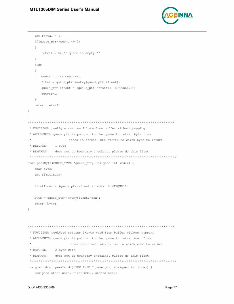
MTLT305D/M Series User’s Manual
_____________________________________________________________________________________
Doc# 7430-3305-09 Page 77
int retval = 0;
if(queue_ptr->count <= 0)
{
retval = 0; /* queue is empty */
}
else
{
queue_ptr -> count--;
*item = queue_ptr->entry[queue_ptr->front];
queue_ptr->front = (queue_ptr->front+1) % MAXQUEUE;
retval=1;
}
return retval;
}
/*******************************************************************************
* FUNCTION: peekByte returns 1 byte from buffer without popping
* ARGUMENTS: queue_ptr is pointer to the queue to return byte from
* index is offset into buffer to which byte to return
* RETURNS: 1 byte
* REMARKS: does not do boundary checking. please do this first
*******************************************************************************/
char peekByte(QUEUE_TYPE *queue_ptr, unsigned int index) {
char byte;
int firstIndex;
firstIndex = (queue_ptr->front + index) % MAXQUEUE;
byte = queue_ptr->entry[firstIndex];
return byte;
}
/*******************************************************************************
* FUNCTION: peekWord returns 2-byte word from buffer without popping
* ARGUMENTS: queue_ptr is pointer to the queue to return word from
* index is offset into buffer to which word to return
* RETURNS: 2-byte word
* REMARKS: does not do boundary checking. please do this first
*******************************************************************************/
unsigned short peekWord(QUEUE_TYPE *queue_ptr, unsigned int index) {
unsigned short word, firstIndex, secondIndex;

MTLT305D/M Series User’s Manual
_____________________________________________________________________________________
Doc# 7430-3305-09 Page 78
firstIndex = (queue_ptr->front + index) % MAXQUEUE;
secondIndex = (queue_ptr->front + index + 1) % MAXQUEUE;
word = (queue_ptr->entry[firstIndex] << 8) & 0xFF00;
word |= (0x00FF & queue_ptr->entry[secondIndex]);
return word;
}
/*******************************************************************************
* FUNCTION: Pop - discard item(s) from queue
* ARGUMENTS: queue_ptr is pointer to the queue
* numToPop is number of items to discard
* RETURNS: return the number of items discarded
*******************************************************************************/
int Pop(QUEUE_TYPE *queue_ptr, int numToPop)
{
int i=0;
char tempchar;
for(i=0; i<numToPop; i++)
{
if(!DeleteQueue(&tempchar, queue_ptr))
{
break;
}
}
return i;
}
/*******************************************************************************
* FUNCTION: Size
* ARGUMENTS: queue_ptr is pointer to the queue
* RETURNS: return the number of items in the queue
*******************************************************************************/
int Size(QUEUE_TYPE *queue_ptr)
{
return queue_ptr->count;
}
/*******************************************************************************
* FUNCTION: Empty
* ARGUMENTS: queue_ptr is pointer to the queue

MTLT305D/M Series User’s Manual
_____________________________________________________________________________________
Doc# 7430-3305-09 Page 79
* RETURNS: return 1 if empty, 0 if not
*******************************************************************************/
int Empty(QUEUE_TYPE *queue_ptr)
{
return queue_ptr->count <= 0;
}
/*******************************************************************************
* FUNCTION: Full
* ARGUMENTS: queue_ptr is pointer to the queue
* RETURNS: return 1 if full, 0 if not full
*******************************************************************************/
int Full(QUEUE_TYPE *queue_ptr)
{
return queue_ptr->count >= MAXQUEUE;
}

MTLT305D/M Series User’s Manual
_____________________________________________________________________________________
Doc# 7430-3305-09 Page 80
Appendix C: RS232 Sample Packet Decoding
Figure 13 Example payload from Angle Data Packet 2 (A2)

MTLT305D/M Series User’s Manual
_____________________________________________________________________________________
Doc# 7430-3305-09 Page 81
Appendix D: Advanced RS232 Port BIT
Built In Test (BIT) and Status Fields
Internal health and status are monitored and communicated in both hardware and software. The
masterFail flag is thrown as a result of a number of instantly fatal conditions (known as a “hard” failure)
or a persistent serious problem (known as a “soft” failure). Soft errors are those which must be triggered
multiple times within a specified time window to be considered fatal. Soft errors are managed using a
digital high-pass error counter with a trigger threshold.
The masterStatus flag is a configurable indication as determined by the user. This flag is asserted as a
result of any asserted alert signals which the user has enabled.
The hierarchy of BIT and Status fields and signals is depicted here:
❖ BITstatus Field
➢ masterFail
▪ hardwareError
▪ comError
• comBIT Field
serialAError
➢ comSerialABIT Field
▪ transmitBufferOverflow
▪ receiveBufferOverflow
▪ framingError
▪ breakDetect
▪ parityError
▪ softwareError
• softwareBIT Field
algorithmError
➢ softwareAlgorithmBIT Field
▪ initialization
▪ overRange
dataError
➢ softwareDataBIT Field
▪ calibrationCRCError
➢ masterStatus
▪ hardwareStatus
• hardwareStatus Field

MTLT305D/M Series User’s Manual
_____________________________________________________________________________________
Doc# 7430-3305-09 Page 82
unlockedEEPROM
▪ softwareStatus
• softwareStatus Field
algorithmInitialization (enabled by default)
highGain (enabled by default)
attitudeOnlyAlgorithm
turnSwitch
▪ sensorStatus
• sensorStatus Field
overRange (enabled by default)
Master BIT and Status (BITstatus) Field
The BITstatus field is the global indication of health and status of the MTLT305D/M Series product . The
LSB contains BIT information and the MSB contains status information.
There are four intermediate signals that are used to determine when masterFail and the hardware BIT
signal are asserted. These signals are controlled by various systems checks in software that are classified
into three categories: hardware, communication, and software. Instantaneous soft failures in each of these
four categories will trigger these intermediate signals, but will not trigger the masterFail until the
persistency conditions are met.
There are four intermediate signals that are used to determine when the masterStatus flag is asserted:
hardwareStatus, sensorStatus, comStatus, and softwareStatus. masterStatus is the logical OR of these
intermediate signals. Each of these intermediate signals has a separate field with individual indication
flags. Each of these indication flags can be enabled or disabled by the user. Any enabled indication flag
will trigger the associated intermediate signal and masterStatus flag.
MTLT305D/M BIT Status Field
BITstatus Field Bits Meaning Category
masterFail 0 0 = normal, 1 = fatal error has occurred BIT
HardwareError 1 0 = normal, 1= internal hardware error BIT
comError 2 0 = normal, 1 = communication error BIT
softwareError 3 0 = normal, 1 = internal software error BIT
Reserved 4:7 N/A
masterStatus 8 0 = nominal, 1 = hardware, sensor, com, or software alert
Status
hardwareStatus 9 0 = nominal, 1 = programmable alert Status
comStatus 10 0 = nominal, 1 = programmable alert Status
softwareStatus 11 0 = nominal, 1 = programmable alert Status
sensorStatus 12 0 = nominal, 1 = programmable alert Status
Reserved 13:15 N/A

MTLT305D/M Series User’s Manual
_____________________________________________________________________________________
Doc# 7430-3305-09 Page 83
comBIT Field
The comBIT field contains flags that indicate communication errors with external devices . Each external
device has an associated message with low level error signals. The comError flag in the BITstatus field is
the bit-wise OR of this comBIT field.
MTLT305D/M COM BIT Field
comBIT Field Bits Meaning Category
serialAError 0 0 = normal, 1 = error Soft
Reserved 2:15 N/A
comSerialABIT Field
The comSerialABIT field contains flags that indicate low level errors with external serial port A (the user
serial port). The serialAError flag in the comBIT field is the bit-wise OR of this comSerialABIT field.
MTLT305D/M Serial Port A BIT Field
comSerialABIT Field Bits Meaning Category
transmitBufferOverflow 0 0 = normal, 1 = overflow Soft
receiveBufferOverflow 1 0 = normal, 1 = overflow Soft
framingError 2 0 = normal, 1 = error Soft
breakDetect 3 0 = normal, 1 = error Soft
parityError 4 0 = normal, 1 = error Soft
Reserved 5:15 N/A
softwareBIT Field
The softwareBIT field contains flags that indicate various types of software errors. Each type has an
associated message with low level error signals. The softwareError flag in the BITstatus field is the bit-
wise OR of this softwareBIT field.
MTLT305D/M Softrware BIT Field
softwareBIT Field Bits Meaning Category
algorithmError 0 0 = normal, 1 = error Soft
dataError 1 0 = normal, 1 = error Soft
Reserved 2:15 N/A
softwareAlgorithmBIT Field
The softwareAlgorithmBIT field contains flags that indicate low level software algorithm errors. The
algorithmError flag in the softwareBIT field is the bit-wise OR of this softwareAlgorithmBIT field.

MTLT305D/M Series User’s Manual
_____________________________________________________________________________________
Doc# 7430-3305-09 Page 84
MTLT305D/M Software Algorithm BIT Field
SoftwareAlgorithmBIT Field Bits Meaning Category
initialization 0 0 = normal, 1 = error during algorithm initialization Hard
overRange 1 0 = normal, 1 = fatal sensor over-range Hard
Reserved 3:15 N/A
softwareDataBIT Field
The softwareDataBIT field contains flags that indicate low level software data errors . The dataError flag
in the softwareBIT field is the bit-wise OR of this softwareDataBIT field.
MTLT305D/M Software Data BIT Field
SoftwareDataBIT Field Bits Meaning Category
calibrationCRCError 0 0 = normal, 1 = incorrect CRC on calibration EEPROM data or data has been compromised by a WE command.
Hard
Reserved 2:15 N/A
hardwareStatus Field
The hardwareStatus field contains flags that indicate various internal hardware conditions and alerts that
are not errors or problems. The hardwareStatus flag in the BITstatus field is the bit-wise OR of the logical
AND of the hardwareStatus field and the hardwareStatusEnable field. The hardwareStatusEnable field is
a bit mask that allows the user to select items of interest that will logically flow up to the masterStatus
flag.
MTLT305D/M Hardware Status BIT Field
hardwareStatus Field Bits Meaning
unlockedEEPROM 3 0=locked, WE disabled, 1=unlocked, WE enabled
Reserved 4:15 N/A
softwareStatus Field
The softwareStatus field contains flags that indicate various software conditions and alerts that are not
errors or problems. The softwareStatus flag in the BITstatus field is the bit-wise OR of the logical AND
of the softwareStatus field and the softwareStatusEnable field. The softwareStatusEnable field is a bit
mask that allows the user to select items of interest that will logically flow up to the masterStatus flag.
MTLT305D/M Software Status Field
softwareStatus Field Bits Meaning
algorithmInit 0 0 = normal, 1 = the algorithm is in initialization mode
Reserved 1 Reserved
attitudeOnlyAlgorithm 2 0 = navigation state tracking, 1 = attitude only state tracking
turnSwitch 3 0 = off, 1 = yaw rate greater than turnSwitch threshold
Reserved 4:15 N/A

MTLT305D/M Series User’s Manual
_____________________________________________________________________________________
Doc# 7430-3305-09 Page 85
sensorStatus Field
The sensorStatus field contains flags that indicate various internal sensor conditions and alerts that are not
errors or problems. The sensorStatus flag in the BITstatus field is the bit-wise OR of the logical AND of
the sensorStatus field and the sensorStatusEnable field. The sensorStatusEnable field is a bit mask that
allows the user to select items of interest that will logically flow up to the masterStatus flag.
MTLT305D/M Sensor Status Field
sensorStatus Field Bits Meaning
overRange 0 0 = not asserted, 1 = asserted
Reserved 1:15 N/A
Configuring the Master Status
The masterStatus byte and its associated programmable alerts are configured using the Read Field and
Write Field command as described in Section 0, Advanced Commands. The below table shows the
definition of the bit mask for configuring the status signals.
MTLT305D/M Master Status Byte Configuration Fields
configuration fields field ID Valid Values Description
hardwareStatusEnable 0x0010 Any Bit mask of enabled hardware status signals
comStatusEnable 0x0011 Any
Bit mask of enabled communication status signals
softwareStatusEnable 0x0012 Any Bit mask of enabled software status signals
sensorStatusEnable 0x0013 Any Bit mask of enabled sensor status signals
hardwareStatusEnable Field
This field is a bit mask of the hardwareStatus field (see BIT and status definitions). This field allows the
user to determine which low level hardwareStatus field signals will flag the hardwareStatus and
masterStatus flags in the BITstatus field. Any asserted bits in this field imply that the corresponding
hardwareStatus field signal, if asserted, will cause the hardwareStatus and masterStatus flags to be
asserted in the BITstatus field.
comStatusEnable Field
This field is a bit mask of the comStatus field (see BIT and status definitions). This field allows the user
to determine which low level comStatus field signals will flag the comStatus and masterStatus flags in the
BITstatus field. Any asserted bits in this field imply that the corresponding comStatus field signal, if
asserted, will cause the comStatus and masterStatus flags to be asserted in the BITstatus field.
softwareStatusEnable Field
This field is a bit mask of the softwareStatus field (see BIT and status definitions). This field allows the
user to determine which low level softwareStatus field signals will flag the softwareStatus and
masterStatus flags in the BITstatus field. Any asserted bits in this field imply that the corresponding
softwareStatus field signal, if asserted, will cause the softwareStatus and masterStatus flags to be asserted
in the BITstatus field. sensorStatusEnable Field

MTLT305D/M Series User’s Manual
_____________________________________________________________________________________
Doc# 7430-3305-09 Page 86
This field is a bit mask of the sensorStatus field (see BIT and status definitions). This field allows the user
to determine which low level sensorStatus field signals will flag the sensorStatus and masterStatus flags
in the BITstatus field. Any asserted bits in this field imply that the corresponding sensorStatus field
signal, if asserted, will cause the sensorStatus and masterStatus flags to be asserted in the BITstatus field.

MTLT305D/M Series User’s Manual
_____________________________________________________________________________________
Doc# 7430-3305-09 Page 87
Appendix E: CAN Command Summary
Data Messages
Message Name PGN Decimal
PF Decimal
PS Decimal
Data Length
Purpose
Slope Sensor Info 2 (SSI2) 61481 240 41 8 Bytes High resolution pitch and roll
Angular Rate Info (ARI) 61482 240 42 8 Bytes Pitch, Roll, Yaw, angular rate
Acceleration Sensor (ACS) 61485 240 45 8 Bytes x, y, z acceleration
Slope Sensor Info (SSI) 61459 240 19 8 Bytes Pitch, Roll angle and pitch rate
High Resolution Acceleration 65388 255 108 8 Bytes High Resolution x, y, z acceleration
Set Messages
Message Name PGN Decimal
PF Decimal
PS Decimal
Payload Length
Purpose
Save Configuration 65361 255 81 3 Bytes Save current configuration to NVM
Reset Algorithm 65360 255 80 3 Bytes Reset Algorithm to initial conditions
Set Packet Rate Divider 65365 255 85 2 Bytes Set rate for broadcast messages
Set Data Packet Types 65366 255 86 2 Bytes Select Packets to be broadcast
Set Filter Cutoff Frequencies 65367 255 87 3 Bytes Set acceleration and rate LPF
Set Orientation 65368 255 88 3 Bytes Set Orientation
Set Unit Behavior 65369 255 89 6 Bytes Set unit behavior
Set Algorithm Control 65371 255 91 8 bytes Set algorithm behavior
Set User Behavior Switches 65375 255 89 4 Bytes Set unit behavior
Set Bank or PS Numbers for Bank 0 65520 255 240 8 Bytes Reconfigure PS numbers for set requests
Set Bank or PS Numbers for Bank 1 65521 255 241 8 Bytes Reconfigure PS numbers for set requests
Parameters Available for Requests Using PGN 60159
Get Parameter name PGN Decimal
PF Decimal
PS Decimal
Payload Length
Purpose
Firmware Version 65242 254 218 5 Bytes Get FW version
ECU ID 64965 253 197 8 Bytes Get Unit ID

MTLT305D/M Series User’s Manual
_____________________________________________________________________________________
Doc# 7430-3305-09 Page 88
Get Parameter name PGN Decimal
PF Decimal
PS Decimal
Payload Length
Purpose
Packet Rate 65365 255 85 2 Bytes Get Packet Rate Setting
Packet Type 65366 255 86 2 Bytes Get Packet types set for broadcast
Filter Cutoff Frequencies 65367 255 87 3 Bytes Get LP Filter settings
Orientation 65368 255 88 3 Bytes Get Orientation settings
User Behavior Switches 65375 255 89 2 Bytes Get unit behavior settings
Hardware BIT status word 65362 255 82 2 Bytes Get HW BIT Status
Software BIT status word 65363 255 83 2 Bytes Get SW BIT Status
Master BIT status word 65364 255 84 2 Bytes Get Master BIT Status
Examples Request and Set Messages for unit with address 0x80 Frame type Frame ID (Hex) Data (HEX) Request Set
Send CAN Extension 18EAFFSA 00 FE DA Firmware Version
Send CAN Extension 18EAFFSA 00 FD C5 Give ECU the sensor ID
Send CAN Extension 18EAFFSA 00 FF 52 Hardware Bit
Send CAN Extension 18EAFFSA 00 FF 53 Software Bit
Send CAN Extension 18EAFFSA 00 FF 54 Sensor Status
Send CAN Extension 18EAFFSA 00 FF 55 Packet Rate Divider
Send CAN Extension 18EAFFSA 00 FF 56 Data Packet Type
Send CAN Extension 18EAFFSA 00 FF 57 Rate and accel LPF
Send CAN Extension 18EAFFSA 00 FF 58 Orientation
Send CAN Extension 18EAFFSA 00 FF 59 unit behavior
Send CAN Extension 18FF51SA 00 80 Configuration Save
Send CAN Extension 18FF50SA 00 80 Algorithm Reset
Send CAN Extension 18FF55SA 80 01 Packet Rate Divider
Send CAN Extension 18FF56SA 80 07 Data Packet Type
Send CAN Extension 18FF57SA 80 19 05 Digital filter
Send CAN Extension 18FF58SA 80 00 00 Orientation
Send CAN Extension 18FF59SA 80 02 00 80 Unit behavior
SA = Source Address
Related Documents