@) Standard variable known impedance Unknown impedance Fig. 6.9 Magic Tee for measurement of impedances. Magic Tee junction from arms (i) an~ as shown in Fig. 6.9. The resultant wave into arm (i) i.e., the null detector can be calculated as follows: . The net wave reaching the mill detector (Refer Fig. 6.9) 1 ( 1 ~ 1 ( 1 ) 1 = ~ 12(!3P~- ~ :J2a3P2 ="2 a3 (PI- P2) ...(6.55) For pe!fect balancing of the bridge (null detection) Eq. 6.55 is equated to zero. . .---- 1 . "2 a3 (pI - P2) = 0 PI - P2 = 0 or PI = P2 ZI - Zz - Z2 - Zz Zl + Zz - Z2 + Zz Zl = Z2 RI+jXI = R2+jX2 RI = R2 and Xl = X2. Thus the unknown impedance can be measured by adjusting the standard variable impedance till the bridge is balanced and both impedances become equal. (b) Magic Tee as a Duplexer : The transmitter and receiver are connected in ports fVand (i)respectively, antenna in the E-arm or port £.e., or or .. £.e., or @ 03Pj -03P j2j2 P,- cell coeff f Z, L 1 P,- cell coeff of Z, CD Z1 j2o3P1 j2o3P2. Z2 (6) - -

Welcome message from author
This document is posted to help you gain knowledge. Please leave a comment to let me know what you think about it! Share it to your friends and learn new things together.
Transcript

@)
Standard variableknown impedance
Unknownimpedance
Fig. 6.9 Magic Tee for measurement of impedances.
Magic Tee junction from arms (i) an~ as shown in Fig. 6.9. Theresultant wave into arm (i) i.e., the null detector can be calculated asfollows: .
The net wave reaching the mill detector (Refer Fig. 6.9)1
(1 ~ 1
(
1
)
1
= ~ 12(!3P~- ~ :J2a3P2 ="2 a3(PI- P2) ...(6.55)For pe!fect balancing of the bridge (null detection) Eq. 6.55 is
equated to zero. ..----
1 .
"2 a3 (pI - P2) = 0
PI - P2 = 0 or PI = P2
ZI - Zz - Z2 - Zz
Zl + Zz - Z2 + Zz
Zl = Z2
RI+jXI = R2+jX2
RI = R2 and Xl = X2.
Thus the unknown impedance can be measured by adjusting thestandard variable impedance till the bridge is balanced and bothimpedances become equal.
(b) Magic Tee as a Duplexer : The transmitter and receiver areconnected in ports fVand (i)respectively, antenna in the E-arm or port
£.e.,
or
or
..
£.e.,
or
@ 03Pj-03Pj2j2
P,- cell coeff f Z, L 1 P,- cell coeff of Z,CD Z1
j2o3P1 j2o3P2.Z2 (6)- -

~ and port@ofMagicTeeisterminatedin a matched load as shown inFig. 6.10. During transmission half the power reaches the antenna fromwhere it is radiated into space. Other half reaches the matched loadwhere it is absorbed without reflections. No transmitter power reachesthe receiver since port ~ and @are isolated ports iil a Magic Tee. Duringreception, half of the received power goes to the receiver and the otherhalf to the transmitter are isolated during reception as well as duringtransmission.
\006~e6
~o\.(J (j)
Fig. 6.10MagicTeeas a Duplexer.
(c) Magic Tee as a Mixer: A Magic Tee can also be used in microwavereceivers as a mixer where the signal and local oscillator are fed intothe E and H arms as shown in Fig. 6.11
Matched load
~ I
I
t
Fig. 6.11 Magic Tee as a mixer.
Half ofthe local oscillator power and half ofthe received power fromantenna goes to the mixer where they are mixed to generate the IFfrequency.
IF = {;n- fo'-

Magic Tee has -many other applications such as a microwavediscriminator, microwave bridge etc.
6.3.5 Rat race junction
This is a four port junction, thefourth port being added to anormal three port Tee. -A typicalrat race junction is shown in Fig.6.12.
The four arms/ports areconnected in the form of anangular ring at proper intervals bymeans of series (or parallel)junctions. These ports areseparated by proper electricallengths to sustain standing waves.For proper operation, it isnecessary that the meancircumference ofthe total race be 1.5 Agand that each ofthe four portsbe separated from its neighbour by a distance of Ag/4.
When power is fed into port (i)it splits equally ( in clockwise andanti clockwise directions) into ports @ and (i)and nothing enters portCD.At ports @ and (i) the powers combine in phase but at port CDcancellation occurs due to Ag/2 path difference. For similar reasons anyinput applied at port G>is equally divided betweel) ports @ and (i)butthe output ai .Jort (j)will be zero. The rat !"acecan also.be used forcombining twu signals or dividing a single signal into two equal halves.If two unequal signals are applied at port (i),an 'output proportional totheir sum will emerge from ports @ aIid (i)while- a differential outputwill appear at port ED.
The scattering matrix of a rat race junction (also caUed hybridjunction) can be written as shown below in ideal conditions (i.e.,neglecting leakage coupling values).
[
0 812 0 814
]
r.'>'L.
= 821 0 823 0~' 0 832 0 834
841 0 843 0
6.4 DmECTIONAL COUPLERS
Directional couplers are flanged, built in waveguide assemblies whichcan sample a small amount of microwave power for measurementpurposes. They can be designed to measure incident and/or reflectedpowers, SWR (Standing Wave Ratio) values, provide a signal path toa receiver or perform other desirable operations. They can beundirectional (measuring only incident power) or bi-directional
3A9/4
~po~a port ,
-~ ( \ ~A9;:a»,m_- F.-o~
"'- /~p. ~
\<Q) A9/4
~ ort @ \- A9/4
Fig. 6.12 Rat-race ring.
...(6.56)

IVU,,-"'-'VVft Vr. ft'l""U ~UAK J:\NLoINJ:\~K1Nt.;
(measuring both incident and reflected) powers. In its most cotnmonform, the directional coupler is a four port waveguide junction consistingof a primary main waveguide and a secondary auxiliary waveguide as'shown in Fig. 6.13a.
Primary waveguide
Port 3
Port 2----------------
Port 1
Port 4
Secondary waveguide
(a)
Receivedpower
~PiPb
---A.N'v-Back power
Main W.G 2 Pr--A,f\./\,-- Receivedpower
Pf--/\.I\/\r-- Coupled
. power
3".~/
...'" ".--- ...---'"4
Aux.W.G
(b)
Fig. 6.13 (a) A schematic of a directional coupler (b) Directional coupler in-dicating powers.
With matched terminations at all its ports, the properties of an idealdirectional coupler can be summarized as follows.
1. A portion of power travelling from port (i) to port @is coupledto port @but not to port @.
2. A portion of power travelling from port @to port @is coupledto port @but notto port @(bidirectional case).
3. A portion of power incident on port @ is coupled to port @ butnot to port @ and a portion of the power incident on port @ iscoupled to port @ but not to port @. Also ports @ and @ aredecoupted as are ports @ and @.
A small portion of input power at port @is coupled to port @so thatmeasurement of this small power is possible. Ideally no power shouldcome out of port @.Fig. 6.13b indicates the various input/output powers.
Pi =incident power at port @.
Pr = received power at port @.
Pr =forward coupled power at port @.
Pb =back power at port @.
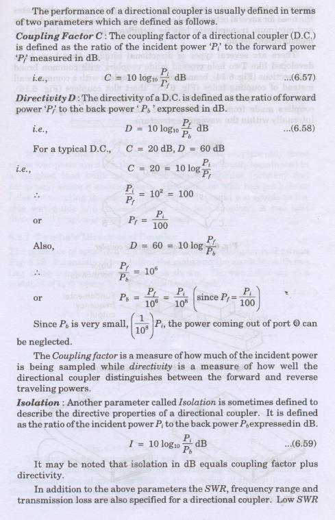
The performance of a directional coupler is usually defined in termsof two parameters which are defined as follows.
Coupling Factor C : The coupling factor of a directional coupler (D.C.)is defined as the ratio of the incident power 'P/ to the forward power'PI measured in dB.
Pi
~.e., C = 10 loglOrr dB ...(6.57)
Directivity D :The directivity of aD. C. is defined as the ratio offorwardpower 'PI to the back power' Pb' expressed in dB.
PD = 1010glO"K dB
For a typical D.C., C = 20 dB, D = 60 dBPi
C = 20 = 101og-Pr
i.e., ...(6.58)
~.e.,
.. Pi = 102= 100Pr
PiPr = 100or
PD = 60 = 10 log---L
Pb
Pr = 106Pb
P p, Pi
(
. P Pi
)or b = ..::::..L-= - sInce r=-
106 108 100
Since Pb is very small, (1~8 )Pi, the power coming out of port tDcanbe neglected.
The Coupling factor is a measure of how much of the incident poweris being sampled while directivity is a measure of how well thedirectional coupler distinguishes between the forward and reversetraveling powers.
Isolation: Another parameter called Isolation is sometimes defined todescribe the directive properties of a directional coupler. It is definedas the ratio ofthe incident power Pi to the back power Pbexpressedin dB.
PiI = 10 10glOPb dB ...(6.59)
It may be noted that isolation in dB equals coupling factor plusdirectivity. .
In addition to the above parameters the SWR, frequency range andtransmission loss are also specified for a directional coupler. Low SWR
Also,
..
~
ensures minimum mismatch errors, wide frequency range eliminatesthe need for several octave band couplers to cover the broad band rangeand minimum transmissiqn loss for significant power availability formeasurement set up.
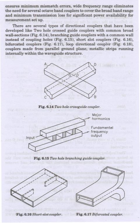
There are several types of directional couplers that have beendeveloped like Two hole crossed guide couplers with common broadwall-sections (Fig. 6.14), branching guide couplers with a common wallinstead of coupling holes (Fig. 6.15), short slot couplers (Fig. 6.16),bifurcated couplers (Fig. 6.17), loop directional coupler (Fig. 6.18),couplers made from parallel ground plane, metallic strips runninginternally within the waveguidestructure. .
Fig. 6.14 Two hole crossguide coupler.
Majorhormonics
Fundamentelfrequencyoutput
Fig. 6.15 Two hole branching guide coupler.
Fig. 6.16 Short-slot coupler. Fig. 6.17 Bifurcated coupler.
~lur[II
~II
w////////////////w///;////////////////////////~
Primary-- coaxial} line
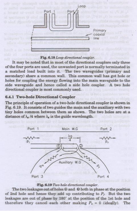
Fig. 6.18 Loopdirectionalcoupler.It may be noted that in most of the directional couplers only three
of the four ports are used, the unwanted port is normally terminated ina matched load built into it. The two waveguides (primary andsecondary) share a common wa~1. This common wall has got hole orholes for coupling the energy flowing into the main waveguide to theside waveguide ~d hence called a side hole coupler. A two holedirectional coupler is most commonly used.
6.4.1 Two-hole Directional Coupler
The principle of operation of a two-hole directional coupler is shown inFig. 6.19. It consists of two guides the main and the auxiliary with twotiny holes common between them as shoWn. The two holes are at adistance of A.g/4 where A.gis the guide wavelength.
Port 1 Main W.G Port 2
-../\IV'--Pi
-¥\/\t'--Pr
Port 3 Port 4
Fig. 6.19 Twoholedirectionalcoupler.The two leakages out of holes ~ and ~ both in phase at the position
of 2nd hole and hence they add up contributing to Pr. But the twoleakages are out of phase by 180. at the position of the 1st hole andtherefore they cancel each other making Pb = 0 (ideQ.lly). The

MJLl<UW A VE AND RADAR ENGINEERING
magnitude of the power coming out of 2 holes depends upon thedimension of the two holes. Since the distance between holes is
'Ag/4, Pb is made '0' (since the incident power will have to travel adistance of ('Ag/4 + Ag/4) when it comes back from hole @ resulting in180. phase shift. compared to incident power leakage through hole (i)entering port @).
The number of holes can be one (as in Bethe crossguide coupler) ormore than two (as in a Multihole coupler). The degree of couplingis determined by size and location of the holes in the waveguide walls.
Although a high degree of directivity can be achieved at a fixedfrequency, it is quite difficult over a band of frequencias. In thisconnection, it should be realized that the frequency determines theseparation of the two holes as a fraction of the wavelength.
6.4.2 Bethe or Single-hole Coupler
A single-hole directional coupler is shown in Fig. 6.20. Here thedirectivity is improved as the Bethe coupler relies on a single hole forcoupling process rather than the separation between two holes. Thepower entering port (i) is coupled to the co-axial probe output and thepower entering port @ in absorbed by the matched load. The auxiliaryguide is placed at such an angle that the magnitude of the magneticallyexcited wave is made equal to that of the electrically excited wave forimproved directivity. In this coupler, the waves in the auxiliary guideare generated through a single hole which includes both electric andmagnetic fields. Because of the phase relationships involved in thecoupling process, the signals generated by the two types of couplingcancel in the forward direction and reinforce in the reverse direction.
Coupling hole
Coaxial probe.output
Matched,load"
Fig. 6.20 Bethe or single-hole coupler.
6.4.3 Scattering Matrix of a Directional Coupler
We us~ the properties of the directional coupler to arrive at the [8]matrix.
1. Directional coupler is a four port network. Hence [8] is a4 x 4 matrix

~u~.. ~ ~l~V I""'V"'1' Cl"Ull"r.r.l'\lf'llL.
From Eqs. 6.69 and 6.72,
..
*P 823 + 823 P = 0P * - 0
[823+ 823] -*"
P'# 0, 823 + 823 = 0
823 = jy
823 = -jy
i.e., 823 must be imaginary.
Let 823 = jq = 814
Therefore,
Since,
...(6.73)
812 = 834 = P (transmission parameter)
and 823 = 814 = jq. Also, p2 + q2 = 1
Substituting these values in Eq. 6.65, [8] matrix of a directionalcoupler is reduced to
[
0 P 0 jq
]
[8] = P ? jq \00 Jq 0 P
jq 0 P 0
6.5 WAVEGUIDE JOINTS
It is not possible to build a waveguide system in one piece and mayrequire several sections connected by joints. These are the waveguidejoints and must be constructed in such a way that a good connectionis made between any two sections of a waveguide without anyirregularities and without affecting the E and H-field patterns.Irregularities in a joint cause reflection effects, create standing wavesand increase the attenuation. A rotating joint could be required as in aradar system where the transmitter/receiver is stationary and theantenna system is revolving.
...(6.74)
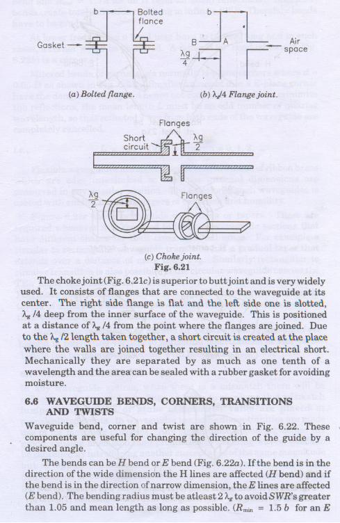
There are several types of waveguide joints. Some of them are shownin Fig. 6.21. The semipermanent butt joints, a bolted flange (Fig. 6.20a)consists of two sections bolted together with a gasket to excludemoisture. For perfect mechanical alignment, it should be ensured thatthere are no bends or discontinuities and the ends of the waveguidesand flanges must have mirror smooth finish to avoid reflection effects.
Figure 6.21b shows a quarter wave length flange joint which usesno mechanical connection and an open circuit at point B creates a shortcircuit at point A due to the standing wave distribution between thesepoints. The field patterns are not disturbed and no discontinuity existsbut there is a possible leakage of energy through the open flange.
~g~
b Boltedfiance
I.-Gasket-
(a) Bolted flange.
Shortcircuit
en A;,
~g-9 ,-,pace(b) A./4 Flange joint.
Flanges
/-g
lH "2
I ;:z
~
(c)Chokejoint.Fig. 6.21
The chokejoint (Fig. 6.21c) is superior to butt joint and is very widelyused. It consists of flanges that are connected to the waveguide at itscenter. The right side flange is flat and the. left side one is slotted,/...g/4 deep from the inner surface of the waveguide. This is positionedat a distance of /...g/4 from the point where the flanges are joined. Dueto the A.g/2 length taken together, a short circuit is created at the placewhere the walls are joined together resulting in an electrical short.Mechanically they are separated by as much as one tenth of awavelength and the areatcan be sealed with a rubber gasket for avoidingmoisture. I
6.6 WAVEGUIDE BENDS, CORNERS, TRANSITIONSAND TWISTS
Waveguide bend, corner and twist are shown in Fig. 6.22. These \
. components are useful for changing the direction of the guide by adesired angle.
The bends can be H bend qr E bend (Fig. 6.22a). Ifthe bend is in thedirection of the wide dimensidn the H lines are affected (H bend) and ifthe bend is in the direction of narrow dimension, the E lines are affected(E bend). The bending rfldius must be atleast 2 Agto avoid SWR's greaterthan 1.05 and mean length as long as possible. (Rmin = 1.5 b for an E

Radius must beat least 2Ag
L=A4~d
H corner
r\l:1E,O
TE11~Circular-Rect
(a)
AgL~
L=4TLJJE corner
(b)
QYE11TE\QRect-Circular
(c)
i (d)
Fig. 6.22 (a) H bend and E bend, (b) H-plane corner and E-plane corner, (c)Circular to rectangular and rectangular to circular transitions (Tapers) (d)
90' twist and 45' twists.
Related Documents