MT800M-AIC 8 th Gen. Intel ® Core™ i7/i5/i3 / Xeon ® E Motherboard with DC_IN 24V Input User’s Manual Version 1.0 (February 2021)

Welcome message from author
This document is posted to help you gain knowledge. Please leave a comment to let me know what you think about it! Share it to your friends and learn new things together.
Transcript
MT800M-AIC
8th Gen. Intel® Core™ i7/i5/i3 / Xeon® E Motherboard with DC_IN 24V Input
User’s Manual
Version 1.0 (February 2021)

ii MT800M-AIC User’s Manual
Copyright
©2021 IBASE Technology, Inc. All rights reserved.
No part of this publication may be reproduced, copied, stored in a retrieval system, translated into any language or transmitted in any form or by any means, electronic, mechanical, photocopying, or otherwise, without the prior written consent of IBASE Technology, Inc. (hereinafter referred to as “IBASE”).
Disclaimer
IBASE reserves the right to make changes and improvements to the products described in this document without prior notice. Every effort has been made to ensure the information in the document is correct; however, IBASE does not guarantee this document is error-free. IBASE assumes no liability for incidental or consequential damages arising from misapplication or inability to use the product or the information contained herein, nor for any infringements of rights of third parties, which may result from its use.
Trademarks
All the trademarks, registrations and brands mentioned herein are used for identification purposes only and may be trademarks and/or registered trademarks of their respective owners.

MT800M-AIC User’s Manual iii
Compliance
In a domestic environment, this product may cause radio interference in which case users may be required to take adequate measures.
This product has been tested and found to comply with the limits for a Class B device, pursuant to Part 15 of the FCC Rules. These limits are designed to provide reasonable protection against harmful interference in a residential installation. This equipment generates, uses and can radiate radio frequency energy and, if not installed and used in accordance with manufacturer’s instructions, may cause harmful interference to radio communications.
WEEE
This product must not be disposed of as normal household waste, in accordance with the EU directive of for waste electrical and electronic equipment (WEEE - 2012/19/EU). Instead, it should be disposed of by returning it to a municipal recycling collection point. Check local regulations for disposal of electronic products.
Green IBASE
This product is compliant with the current RoHS restrictions and prohibits use of the following substances in concentrations exceeding 0.1% by weight (1000 ppm) except for cadmium, limited to 0.01% by weight (100 ppm).
• Lead (Pb) • Mercury (Hg) • Cadmium (Cd) • Hexavalent chromium (Cr6+) • Polybrominated biphenyls (PBB) • Polybrominated diphenyl ether (PBDE)
iv MT800M-AIC User’s Manual
Important Safety Information
Carefully read the precautions before using the board.
Environmental conditions:
• Use this product in environments with ambient temperatures between 0˚C and 60˚C.
• Do not leave this product in an environment where the storage temperature may be below -20°C or above 80°C.
Care for your IBASE products:
• Before cleaning the PCB, unplug all cables and remove the battery. • Clean the PCB with a circuit board cleaner, degreaser, or use cotton
swabs and alcohol.
• Vacuum the dust with a computer vacuum cleaner to prevent the fan from being clogged.
WARNING
Attention during use:
• Do not use this product near water. • Do not spill water or any other liquids on this product.
• Do not place heavy objects on the top of this product.
Anti-static precautions
• Wear an anti-static wrist strap to avoid electrostatic discharge. • Place the PCB on an anti-static kit or mat.
• Hold the edges of PCB when handling. • Touch the edges of non-metallic components of the product instead of
the surface of the PCB. • Ground yourself by touching a grounded conductor or a grounded bit
of metal frequently to discharge any static.
CAUTION
Replace only with the same or equivalent type recommended by the manufacturer. Dispose of used batteries according to the manufacturer’s instructions or recycle them at a local recycling facility or battery collection point.
MT800M-AIC User’s Manual v
Warranty Policy
• IBASE standard products:
24-month (2-year) warranty from the date of shipment. If the date of shipment cannot be ascertained, the product serial numbers can be used to determine the approximate shipping date.
• 3rd-party parts:
12-month (1-year) warranty from delivery for the 3rd-party parts that are not manufactured by IBASE, such as CPU, CPU cooler, memory, storage devices, power adapter, panel and touchscreen.
* PRODUCTS, HOWEVER, THAT FAIL DUE TO MISUSE, ACCIDENT, IMPROPER INSTALLATION OR UNAUTHORIZED REPAIR SHALL BE TREATED AS OUT OF WARRANTY AND CUSTOMERS SHALL BE BILLED FOR REPAIR AND SHIPPING CHARGES.
Technical Support & Services
1. Visit the IBASE website at www.ibase.com.tw to find the latest information about the product.
2. If you need any further assistance from your distributor or sales representative concerning problems that you may have encountered, please prepare the following information:
• Product model name • Product serial number • Detailed description of the problem
• The error messages in text or in screenshots if there is any • The arrangement of the peripherals • Software in use (such as OS and application software, including
the version numbers)
3. If repair service is required, you can download the RMA form athttp://www.ibase.com.tw/english/Supports/RMAService/. Fill out the form and contact your distributor or sales representative.

vi MT800M-AIC User’s Manual
Table of Contents
Chapter 1 General Information ................................ 1
1.1 Introduction ......................................................................................... 2 1.2 Features .............................................................................................. 2 1.3 Packing List ......................................................................................... 3 1.4 Optional Accessories ........................................................................... 3 1.5 Specifications ...................................................................................... 4 1.6 Block Diagram ..................................................................................... 6 1.7 Board View .......................................................................................... 7 1.8 Dimensions ......................................................................................... 9
Chapter 2 Hardware Configuration ......................... 11
2.1 Installations ....................................................................................... 12 2.1.1 Installing the Memory ........................................................... 12
2.2 Setting the Jumpers ........................................................................... 13 2.3 Jumpers& Connectors on MT800M-AIC ............................................ 14 2.4 Jumpers Quick Reference ................................................................. 15
2.4.1 AT/ATX Mode Setting (JP1) ................................................ 15 2.4.2 Clear CMOS Setting (JP2)................................................... 16 2.4.3 Clear ME Setting (JP3) ........................................................ 16 2.4.4 Flash Descriptor Security Override (Factory use) JP4 .......... 17
2.5 Connectors Quick Reference ............................................................. 18 2.5.1 80 Port Debug Tool Connectors (J1) .................................... 19 2.5.2 X16 Slot, Not Standard but for IP-T803 use (PCIE1) ............ 19 2.5.3 USB 3.1 Ports (CN3, CN4) .................................................. 19 2.5.4 Front Panel Settings Connector (J2) .................................... 20 2.5.5 COM3, COM4, COM5, COM6 Ports (J10, J11, J9, J8) ......... 21 2.5.6 COM1& COM2 RS-232/422/485 Ports (CN12) .................... 22 2.5.7 SPI Flash Tool Header (Factory use only) (J12) ................... 23 2.5.8 MXM Power Connector (19V) - (J13) .................................... 23 2.5.9 DC_IN 24V Power Connector (J14) ...................................... 23 2.5.10 Gigabit LAN Header (J15, J16, J17, J18) ............................ 24 2.5.11 Digital I/O Connector (J20) ................................................... 24 2.5.12 SATA HDD Power Conn. (SATAPWR1, SATAPWR2) ......... 25 2.5.13 SIM Card Socket (CN5) ........................................................ 25 2.5.14 Fan Power Connector (CPU_FAN1 & SYS_Fan1) ............... 26

MT800M-AIC User’s Manual vii
Chapter 3 Drivers Installation ............................... 27
3.1 Introduction ........................................................................................28 3.2 Intel® Chipset Software Installation Utility ...........................................28 3.3 HD Graphics Driver Installation ..........................................................29 3.4 HD Audio Driver Installation ...............................................................31 3.5 LAN Driver Installation .......................................................................32 3.6 Intel® Management Engine Drivers Installation ...................................33
Chapter 4 BIOS Setup ........................................... 35
4.1 Introduction ........................................................................................36 4.2 BIOS Setup ........................................................................................36 4.3 Main Settings .....................................................................................37 4.4 Advanced Settings .............................................................................38 4.5 Chipset Settings .................................................................................48 4.6 SecuritySettings .................................................................................51 4.7 Boot Settings .....................................................................................52 4.8 Save & ExitSettings ...........................................................................53
Appendix ..................................................................... 54
A. I/O Port Address Map ........................................................................55 B. Interrupt Request Lines (IRQ) ............................................................57 C. Watchdog Timer Configuration ...........................................................59 D. On-Board Connector Types ...............................................................63


1
Chapter 1 General Information
The information provided in this chapter includes:
• Features
• Packing List
• Specifications
• Block Diagram
• Board View
• Board Dimensions

2 MT800M-AIC User’s Manual
1.1 Introduction
MT800M-AIC is a motherboard based on the Intel® 8th Generation Processor that features DC_IN 24V input two DDR memory sockets and supports up to 32 GB and high-performance graphics processing to create media-rich content and brilliant HD entertainment with DVI-D, VGA and DisplayPort display interface. Other advanced features on board include watchdog timer and Digital I/O.
MT800M-AIC
1.2 Features
• 8th Gen. Intel® Xeon® E / Core™ i7/i5/i3 processor
• 2x DDR4 SO-DIMM, expandable up to 32GB
• Intel® processor integrated graphics device for DVI-D, VGA and DisplayPort
• 4 x GbE LAN, 6x USB 3.1, 6x COM, 2x SATAIII
• 1x MXM3.0, 3x PCIe (x4)in PCIE1 Slot, 1x Mini-PCIe, 1x M.2(M2280)
• Configurable watchdog timer and digital I/O

General Information
MT800M-AIC User’s Manual 3
1
1.3 Packing List
Your MT800M-AIC package should include the items listed below. If any of the items below is missing, contact the distributor or dealer from whom you purchased the product.
• MT800M-AICMotherboard x 1
• Disk x 1 (with chipset drivers)
• This User’s Manual x 1
1.4 Optional Accessories
IBASE provides optional accessories listed below. Please contact us or your dealer if you have any requirements.
• USB 3.0 cable (USB-3K)

4 MT800M-AIC User’s Manual
1.5 Specifications
Product Name MT800M-AIC
System
Operating System
• Windows 10 (64-bit)
• Linux Fedora (64-bit) & Ubuntu (64-bit)
• Windows Server
CPU Socket LGA1151 for 8thGen. Intel® Xeon® E / CoreTM i7/i5/i3 HC/QC/DC processors
Chipset Intel® Q370 PCH
Memory 2x DDR4-2400 SO-DIMM 6GB, Max. 32GB
Storage M.2 M2280 slot supporting NVMe for SSD & Mini-PCIe slot for mSATA
Graphics HD graphics integrated into the processor
Network Controller
1st LAN: Intel® I219LM GbE 2nd ~4th LAN: Intel® I211AT GbE
Super I/O Fintek F81966D-I
Audio Built-in High Definition Audio controller, plus Realtek audio codec ALC662S-VD0-GR
Power Supply DC_IN 24V
H/W Monitor Yes
Watchdog Timer
Yes (256 segments, 0, 1, 2…255 sec / min)
BIOS AMI BIOS
RAID RAID 0/1/5/10
RoHS Yes
Dimensions 200mm x 270mm
Certification CE(EN55032:2012), FCC Class B, LVD

General Information
MT800M-AIC User’s Manual 5
1
I/O Ports
Display
• 1 x DisplayPort1.2 (4096 x 2160 at 60 Hz)
• 1 x DVI-D (1920 x 1600 at 60 Hz)
• 1 x VGA
• 1 x DisplayPort for MXM
LAN 4x RJ45 GbE LAN
USB
• 2x USB3.1 (edge I/O connectors)
• 2x USB3.1 onboard connectors: 4 ports via box-headers,
• 2x USB2.0 (edge I/O connectors)
Serial
6 x COM ports:
• COM1 & COM2: RS-232/422/485 (I/O coastline connectors, jumper-less selection)
• COM3 ~ COM6: RS-232 only (via on-board box-headers)
SATA 2x SATA 3.0
Audio Jack 1 x Line-Out, 1 x Mic-In
Digital IO 4-In & 4-Out
SSD 1slot for M.2 (M2280), 1 slot for mSATA
Expansion Slots
• 1 x MXM3.0
• 3 x PCIe (x4) in PCIE1 slot
• 1 x PCIe (x1) slot
• 1 x full-size Mini-PCIe slot
• 1 x M.2 M2280 slot
Environment
Temperature • Operating: 0~60 °C (32 ~ 140 °F)
• Storage: -20 ~ 80 °C (-4 ~ 176°F)
Relative Humidity
0 ~ 90 %, non-condensing at 60 °C
All specifications are subject to change without prior notice.

6 MT800M-AIC User’s Manual
1.6 Block Diagram

General Information
MT800M-AIC User’s Manual 7
1
1.7 Board View
Top View
Bottom View

8 MT800M-AIC User’s Manual
I/O View
No. Name No. Name
1 VGAPort 6 Mic-In & Line out
2 DVI-D Port 7
LED for EtheNET port *Green for power LED 3 USB 3.1 (Gen1) / USB 2.0
4 DP++ (left) & DP (MXM)
(right) 8
LED for Power/HDD /2x error warning
5 COM1 / COM2 Ports 10 Power Button

General Information
MT800M-AIC User’s Manual 9
1
1.8 Dimensions

10 MT800M-AIC User’s Manual
This page is intentionally left blank.

11
Chapter 2 Hardware Configuration
This section provides information on jumper settings and connectors on the board in order to set up a workable system. The topics covered are:
• Essential installations before you begin: CPU and the memory
• Jumpers and connectors

12 MT800M-AIC User’s Manual
2.1 Installations
2.1.1 Installing the Memory
To install the modules, locate the memory slot on the board and perform the following steps:
1. Press the ejector tabs of the memory slot down and outwards with your fingertips.
2. Hold the meomry module and align the key of the module with that on the memory slot.
3. Gently push the module in an upright position until the ejector tabs of the memory slot close to hold the module in place when the module touches the bottom of the slot.
To remove the module, press the ejector tabs outwards with your fintertips to eject the module.

Hardware Configuration
MT800M-AIC User’s Manual 13
2
2.2 Setting the Jumpers
Set up and configure this board by using jumpers for various settings and features according to your needs and applications. Contact your supplier if you have doubts about the best configuration for your use.
2.2.1 How to Set Jumpers
Jumpers are short-length conductors consisting of several metal pins with a non-conductive base mounted on the circuit board. Jumper caps are used to have the functions and features enabled or disabled. If a jumper has 3 pins, you can connect either PIN1 to PIN2 or PIN2 to PIN3 by shorting.
A 3-pin jumper A jumper cap
Refer to the illustration below to set jumpers.
Pin closed Oblique view Illustration
Open
1-2
2-3
When two pins of a jumper are encased in a jumper cap, this jumper is closed, i.e. turned On.
When a jumper cap is removed from two jumper pins, this jumper is open, i.e. turned Off.
Pin# 1 2 3
1 2 3
1 2 3
1 2 3
14 MT800M-AIC User’s Manual
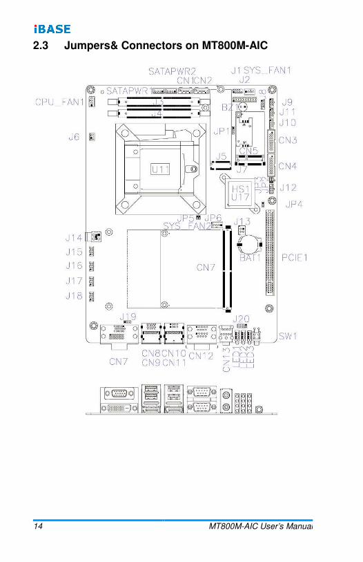
2.3 Jumpers& Connectors on MT800M-AIC

Hardware Configuration
MT800M-AIC User’s Manual 15
2
2.4 Jumpers Quick Reference
Function Jumper Page
AT/ATX Mode Setting JP1 15
Clear CMOS Setting JP3 16
Clear ME Setting JP3 16
Flash Descriptor Security Override (Factory use) JP4 17
2.4.1 AT/ATX Mode Setting (JP1)
Function Pin closed Illustration
AT Mode 1-2
ATX Mode(default) 2-3
1
1
16 MT800M-AIC User’s Manual
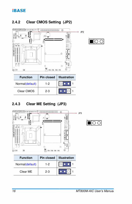
2.4.2 Clear CMOS Setting (JP2)
Function Pin closed Illustration
Normal(default) 1-2
Clear CMOS 2-3
2.4.3 Clear ME Setting (JP3)
Function Pin closed Illustration
Normal(default) 1-2
Clear ME 2-3
1
1
1
1
Hardware Configuration
MT800M-AIC User’s Manual 17
2
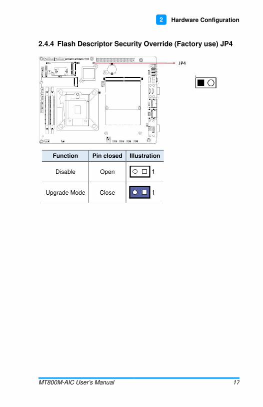
2.4.4 Flash Descriptor Security Override (Factory use) JP4
Function Pin closed Illustration
Disable Open
Upgrade Mode Close
1
1

18 MT800M-AIC User’s Manual
2.5 Connectors Quick Reference
Function Connector Page
80 Port Debug Tool Connectors J1 19
X16 Slot, Not Standard but for IP-T803 use PCIE1 19
USB 3.1 Ports CN3, CN4 19
Front Panel Settings Connector J2 20
COM3, COM4, COM5, COM6 RS-232 Ports
J10, J11, J9, J8 21
COM1 & COM2 RS-232/422/485 Ports CN12 22
SPI Flash Tool Header (Factory use only) J12 23
MXM Power Connector (19V) J13 23
Gigabit LAN Header J15, J16, J17, J18 24
Digital I/O Connector J20 24
SATA HDD Power Connectors SATAPWR1, SATAPWR2
25
SIM Card Socket CN5 25
Fan Power Connector CPU_FAN1 &
SYS_Fan2 26

Hardware Configuration
MT800M-AIC User’s Manual 19
2
2.5.1 80 Port Debug Tool Connectors (J1)
J1 is for factory use only.
2.5.2 X16 Slot, Not Standard but for IP-T803 use (PCIE1)
2.5.3 USB 3.1 Ports (CN3, CN4)
Pin Signal Name Pin Signal Name
1 VCC 11 P2_U2_D+
2 P1_SSRX- 12 P2_U2_D-
3 P1_SSRX+ 13 Ground
4 Ground 14 P2_SSTX+
5 P1_SSTX- 15 P2_SSTX-
6 P1_SSTX+ 16 Ground
7 Ground 17 P2_SSRX+
8 P1_U2_D- 18 P2_SSRX-
9 P1_U2_D+ 19 VCC
10 NC P2_U2_D+

20 MT800M-AIC User’s Manual
2.5.4 Front Panel Settings Connector (J2)
Pin Signal Name Pin Signal Name
1 Power LED+ 2 SPK
3 Ground 4 NC
5 Power LED- 6 Ground
7 NC 8 SPK(VCC)
9 Ground 10 NC
11 Ground 12 NC
13 Power BTN 14 Power BTN
15 NC 16 NC
17 Reset BTN 18 Reset BTN
19 HDD LED+ 20 HDD LED-
J2 is utilized for system indicators to provide light indication of the computer activities and switches to change the computer status. It provides interfaces for the following functions.
• ATX Power ON Switch (Pins 13 and 14)
The 2 pins make an “ATX Power Supply On/Off Switch” for the system that connects to the power switch on the case. When pressed, the power switch will force the system to power on. When pressed again, it will power off the system.
• Hard Disk Drive LED Connector (Pins 19 and 20)
This connector connects to the hard drive activity LED on control panel. This LED will flash when the HDD is being accessed.

Hardware Configuration
MT800M-AIC User’s Manual 21
2
• Reset Switch (Pins 17 and 18)
The reset switch allows you to reset the system without turning the main power switch off and then on again. Orientation is not required when making a connection to this header.
• Power LED (Pins 1 and 5)
This connector connects to the system power LED on control panel. This LED will light when the system turns on.
• Speaker Connector (Pins 2 and 8)
Connect the two pins for setting up the system output speaker.
2.5.5 COM3, COM4, COM5, COM6 RS-232 Ports (J10, J11, J9, J8)
Pin Signal Name Pin Signal Name
1 DCD, Data carrier detect 2 DSR, Data set ready
3 RXD, Receive data 4 RTS, Request to send
5 TXD, Transmit data 6 CTS, Clear to send
7 DTR, Data terminal ready
8 RI, Ring indicator
9 Ground 10 Key
22 MT800M-AIC User’s Manual
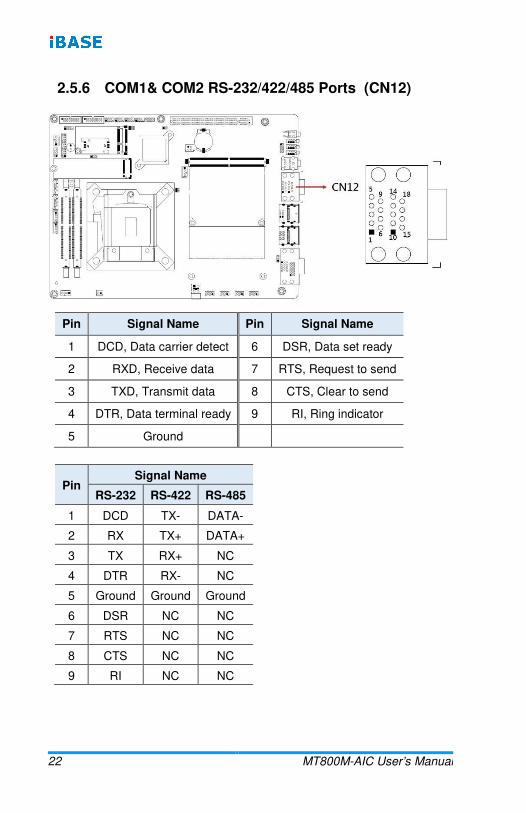
2.5.6 COM1& COM2 RS-232/422/485 Ports (CN12)
Pin Signal Name Pin Signal Name
1 DCD, Data carrier detect 6 DSR, Data set ready
2 RXD, Receive data 7 RTS, Request to send
3 TXD, Transmit data 8 CTS, Clear to send
4 DTR, Data terminal ready 9 RI, Ring indicator
5 Ground
Pin Signal Name
RS-232 RS-422 RS-485
1 DCD TX- DATA-
2 RX TX+ DATA+
3 TX RX+ NC
4 DTR RX- NC
5 Ground Ground Ground
6 DSR NC NC
7 RTS NC NC
8 CTS NC NC
9 RI NC NC
Hardware Configuration
MT800M-AIC User’s Manual 23
2
2.5.7 SPI Flash Tool Header (Factory use only) (J12)
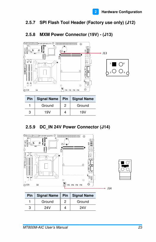
2.5.8 MXM Power Connector (19V) - (J13)
Pin Signal Name Pin Signal Name
1 Ground 2 Ground
3 19V 4 19V
2.5.9 DC_IN 24V Power Connector (J14)
Pin Signal Name Pin Signal Name
1 Ground 2 Ground
3 24V 4 24V

24 MT800M-AIC User’s Manual
2.5.10 Gigabit LAN Header (J15, J16, J17, J18)
Pin Signal Name Pin Signal Name
1 LAN_XMDI0P 2 LAN_XMDI0N
3 LAN_XMDI1P 4 LAN_XMDI1N
5 LAN_XMDI2N 6 LAN_XMDI2P
7 LAN_XMDI3P 8 LAN_XMDI3N
2.5.11 Digital I/O Connector (J20)
Pin Signal Name Pin Signal Name
1 Ground 2 +5V
3 OUT3 4 OUT1
5 OUT2 6 OUT0
7 IN3 8 IN1
9 IN2 10 IN0

Hardware Configuration
MT800M-AIC User’s Manual 25
2
2.5.12 SATA HDD Power Connectors (SATAPWR1, SATAPWR2)*
* (E-CALL 0110-071-040)
Pin Signal Name Pin Signal Name
1 +5V 2 Ground
3 Ground 4 +12V
2.5.13 SIM Card Socket (CN5)
Pin Signal Name Pin Signal Name
4 Ground 1 VCC
5 VPP 2 RESET
6 DATA 3 CLOCK
26 MT800M-AIC User’s Manual
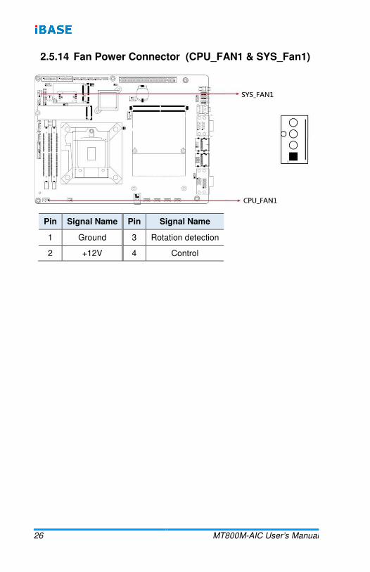
2.5.14 Fan Power Connector (CPU_FAN1 & SYS_Fan1)
Pin Signal Name Pin Signal Name
1 Ground 3 Rotation detection
2 +12V 4 Control

27
Chapter 3 Drivers Installation
This chapter introduces installation of the following drivers:
• Intel® Chipset Software Installation Utility
• HD Graphics Driver
• HD Audio Driver
• LAN Driver
• Intel® Management Engine Drivers Installation
28 MT800M-AIC User’s Manual
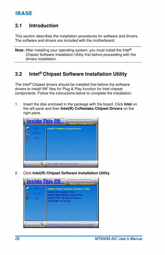
3.1 Introduction
This section describes the installation procedures for software and drivers. The software and drivers are included with the motherboard.
Note: After installing your operating system, you must install the Intel® Chipset Software Installation Utility first before proceeding with the drivers installation.
3.2 Intel® Chipset Software Installation Utility
The Intel® Chipset drivers should be installed first before the software drivers to install INF files for Plug & Play function for Intel chipset components. Follow the instructions below to complete the installation.
1. Insert the disk enclosed in the package with the board. Click Intel on the left pane and then Intel(R) Coffeelake Chipset Drivers on the right pane.
2. Click Intel(R) Chipset Software Installation Utility.

Driver Installation
MT800M-AIC User’s Manual 29
3
3. When the Welcome screen to the Intel® Chipset Device Software appears, click Next to continue.
4. Accept the software license agreement and proceed with the installation process.
5. On the Readme File Information screen, click Install for installation.
6. The driver has been completely installed. Restart the computer for changes to take effect.
3.3 HD Graphics Driver Installation
1. Click Intel on the left pane and then Intel(R) Coffeelake Chipset Drivers on the right pane.
2. Click Intel(R) HD Graphics Driver.

30 MT800M-AIC User’s Manual
3. When the Welcome screen appears, click Next to continue.
4. Accept the license agreement and click Next.
5. On the Readme File Information screen, click Next until the installation starts.
6. When Setup is Complete, restart the computer for changes totake effect.

Driver Installation
MT800M-AIC User’s Manual 31
3
3.4 HD Audio Driver Installation
1. Click Intel on the left pane and then Intel(R) Coffeelake Chipset Drivers on the right pane.
2. Click Realtek High Definition Audio Driver.
3. On the Welcome screen of the InstallShield Wizard, click Next.
4. Click Next until the installation starts.
5. The driver has been completely installed. Restart the computer for changes to take effect.
32 MT800M-AIC User’s Manual
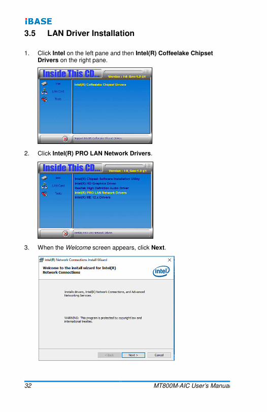
3.5 LAN Driver Installation
1. Click Intel on the left pane and then Intel(R) Coffeelake Chipset Drivers on the right pane.
2. Click Intel(R) PRO LAN Network Drivers.
3. When the Welcome screen appears, click Next.

Driver Installation
MT800M-AIC User’s Manual 33
3
4. Accept the license agreement and click Next.
5. On the Setup Options screen, click the checkbox to select the desired driver(s) for installation. Then click Next to continue.
6. The wizard is ready to begin installation. Click Install.
7. As the installation is complete, click Finish.
3.6 Intel® Management Engine Drivers Installation
1. Click Intel on the left pane and then Intel(R) Coffeelake Chipset Drivers on the right pane.
34 MT800M-AIC User’s Manual
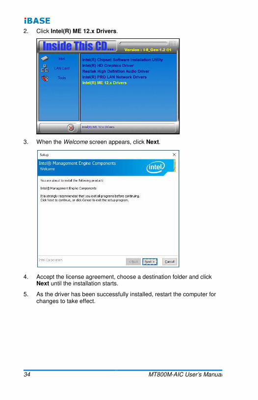
2. Click Intel(R) ME 12.x Drivers.
3. When the Welcome screen appears, click Next.
4. Accept the license agreement, choose a destination folder and click Next until the installation starts.
5. As the driver has been successfully installed, restart the computer for changes to take effect.
35
Chapter 4 BIOS Setup
This chapter describes the different settings available in the AMI BIOS that comes with the board. The topics covered in this chapter are as follows:
• Main Settings
• Advanced Settings
• Chipset Settings
• Boot Settings
• Security Settings
• Save & Exit
36 MT800M-AIC User’s Manual
4.1 Introduction
The BIOS (Basic Input/Output System) installed in the ROM of your computer system supports Intel® processors. The BIOS provides critical low-level support for standard devices such as disk drives, serial ports and parallel ports. It also provides password protection as well as special support for detailed fine-tuning of the chipset controlling the entire system.
4.2 BIOS Setup
The BIOS provides a Setup utility program for specifying the system configurations and settings. The BIOS ROM of the system stores the Setup utility. When you turn on the computer, the BIOS is immediately activated. Press the <Del> key immediately allows you to enter the Setup utility. If you are a little bit late pressing the <Del> key, POST (Power On Self Test) will continue with its test routines, thus preventing you from invoking the Setup.
If you still need to enter Setup, restart the system by pressing the ”Reset” button or simultaneously pressing the <Ctrl>, <Alt> and <Delete> keys.
You can also restart by turning the system Off and back On again.
The following message will appear on the screen:
Press <DEL> to Enter Setup
In general, press the arrow keys to highlight items,<Enter> to select, the <PgUp> and <PgDn> keys to change entries, <F1> for help, and <Esc> to quit.
When you enter the BIOS Setup utility, the Main Menu screen will appear on the screen. The Main Menu allows you to select from various setup functions and exit choices.
Warning: It is strongly recommended that you avoid making any changes to the chipset defaults.
These defaults have been carefully chosen by both AMI and your system manufacturer to provide the absolute maximum performance and reliability. Changing the defaults could make the system unstable and crash in some cases.

BIOS Setup
MT800M-AIC User’s Manual 37
4
4.3 Main Settings
BIOS Setting Description
System Date
Sets the date. Use Tab to switch between the data elements.
Default Ranges: Year: 2005-2099 Months: 1-12 Days: depends on the month
System Time Set the time. Use Tab to switch between the Time elements.
38 MT800M-AIC User’s Manual
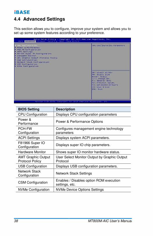
4.4 Advanced Settings
This section allows you to configure, improve your system and allows you to set up some system features according to your preference.
BIOS Setting Description
CPU Configuration Displays CPU configuration parameters
Power & Performance
Power & Performance Options
PCH-FW Configuration
Configures management engine technology parameters
ACPI Settings Displays system ACPI parameters.
F81966 Super IO Configuration
Displays super IO chip parameters.
Hardware Monitor Shows super IO monitor hardware status.
AMT Graphic Output Protocol Policy
User Select Monitor Output by Graphic Output Protocol
USB Configuration Displays USB configuration parameters.
Network Stack Configuration
Network Stack Settings
CSM Configuration Enables / Disables option ROM execution settings, etc.
NVMe Configuration NVMe Device Options Settings

BIOS Setup
MT800M-AIC User’s Manual 39
4
4.4.1 CPU Configuration
BIOS Setting Description
Intel(VMX) Virtualization Technology
When enabled, a VMM can utilize the additional hardware capabilities provided by Vanderpool Technology.
Active Processor Cores
Number of cores to enable in each processor package.
Options: All, 1, 2, 3
AES Enables / Disables AES (Advanced Encryption Standard).

40 MT800M-AIC User’s Manual
4.4.2 Power & Performance
BIOS Setting Description
CPU – Power Management Control
CPU – Power Management Control Options
Intel SpeedStep Allows more than two frequency ranges to be supported
Intel Speed Shift Technology
This can be Enabled or Disabled.
4.4.3 PCH-FW Configuration

BIOS Setup
MT800M-AIC User’s Manual 41
4
4.4.4 ACPI Settings
BIOS Setting Description
Enable Hibernation Enables / Disables the system ability to hibernate (OS/S4 Sleep State). This option may be not effective with some OS.
ACPI Sleep State
Selects an ACPI sleep state where the system will enter when the Suspend button is pressed.
Options: Suspend Disabled, S3 (Suspend to RAM)

42 MT800M-AIC User’s Manual
4.4.5 F81966 Super IO Configuration
BIOS Setting Description
Serial Port Configuration
Setsparameters of Serial Ports.
Enables /Disables the serial port and select an optimal setting for the Super IO device.

BIOS Setup
MT800M-AIC User’s Manual 43
4
4.4.6 Hardware Monitor
BIOS Setting Description
CPU Smart Fan Control
Enables /Disables the CPU smart fan feature.
Options: Disabled / 50 °C / 60 °C / 70 °C / 80 °C
SystemSmart Fan Control
Enables /Disables the system smart fan feature.
Options: Disabled / 50 °C / 60 °C / 70 °C / 80 °C
Temperatures/Voltages
These fields are the parameters of the hardware monitoring function feature of the motherboard. The values are read-only values as monitored by the system and show the PC health status.
CPU Shutdown Temperature
Options: Disabled / 70 °C / 75°C / 80°C / 85 °C / 90 °C / 95 °C
4.4.7 AMI Graphic Output Protocol Policy
BIOS Setting Description
44 MT800M-AIC User’s Manual
Output Select Selects the display output interface
BIOS Setup
MT800M-AIC User’s Manual 45
4
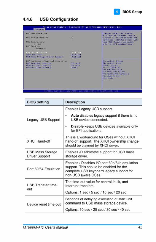
4.4.8 USB Configuration
BIOS Setting Description
Legacy USB Support
Enables Legacy USB support.
• Auto disables legacy support if there is no USB device connected.
• Disable keeps USB devices available only for EFI applications.
XHCI Hand-off This is a workaround for OSes without XHCI hand-off support. The XHCI ownership change should be claimed by XHCI driver.
USB Mass Storage Driver Support
Enables /Disablesthe support for USB mass storage driver.
Port 60/64 Emulation
Enables / Disables I/O port 60h/64h emulation support. This should be enabled for the complete USB keyboard legacy support for non-USB aware OSes.
USB Transfer time-out
The time-out value for control, bulk, and Interrupt transfers.
Options: 1 sec / 5 sec / 10 sec / 20 sec
Device reset time-out
Seconds of delaying execution of start unit command to USB mass storage device.
Options: 10 sec / 20 sec / 30 sec / 40 sec

46 MT800M-AIC User’s Manual
BIOS Setting Description
Device power-up delay
The maximum time the device will take before it properly reports itself to the Host Controller.
Auto uses default value for a Root port it is 100ms. But for a Hub port, the delay is taken from Hub descriptor.
Options: Auto / Manual
Mass Storage Devices
Mass storage device emulation type. ‘Auto’ enumerates devices according to their media format. Optical devices are emulated as ‘CDROM’. Drives with no media will be emulated according to a drive type.

BIOS Setup
MT800M-AIC User’s Manual 47
4
4.4.9 Network Stack Configuration
BIOS Setting Description
Network Stack Enable/Disable UEFI Network Stack.
4.4.10 CSM Configuration
BIOS Setting Description
CSM Support Enables / Disables CSM support.
Network
Controls the execution of UEFI and Legacy PXE OpROM.
Options: Do not launch / Legacy
4.4.11 NVMe Configuration
BIOS Setting Description
NVMe Configuration NVMe controller and drive information.

48 MT800M-AIC User’s Manual
4.5 Chipset Settings
BIOS Setting Description
System Agent (SA) Configuration
System Agent (SA) parameters
PCH-IO Configuration
PCH parameters
4.5.1 System Agent (SA) Configuration
BIOS Setting Description
Graphics Configuration
Configures the graphics settings.
VT-d Checks if VT-d function on MCH is supported.

BIOS Setup
MT800M-AIC User’s Manual 49
4
4.5.1.1. Graphics Configuration
BIOS Setting Description
Grapics Turbo IMON Current
Graphics turbo IMON current values supported (14-31)
Skip Scanning of External Gfx Card
If enabled, it will not scan for external Gfx Card on PEG and PCH PCIE ports.
Primary Display The default setting is Auto.
External Gfx Card Primary Display Configuration
Configures the external Gfx card primary display.
• Primary PEG: Selects the primary PEG (options: Auto / PEG11 / PEG12).
• Primary PCIE: Selects the primary PCIe (options: Auto / PCIE1 ~ PCIE18)
Internal Graphics Keep IGFX enabled based on the setup options.
Options: Auto / Disabled / Enabled
GTT Size Sets the GTT size as 2 MB, 4 MB, or 8 MB.
Aperture Size
Sets the aperture size as 128 MB / 256 MB / 512 MB / 1024 MB / 2048 MB.
Note: Above 4 GB MMIO BIOS assignment is automatically enabled when selecting 2048 MB aperture. To use this feature, disable CSM support.
DVMT Pre-Allocated
Sets DVMT 5.0 pre-allocated (fixed) graphics memory size used by the internal graphics devce.
Options: 0M / 32M / 64M / 4M / 8M / 12M / 16M / 20M / 24M / 28M / 32M/F7 / 36M / 40M / 44M / 48M / 52M / 56M / 60M
DVMT Total Gfx Mem
Selects DVMT 5.0 total graphic memory size used by the internal graphcis device.
Options: 256M / 128M / MAX

50 MT800M-AIC User’s Manual
4.5.2 PCH-IO Configuration
BIOS Setting Description
SATA and RST Configuration
Configures SATA devices.
PCH LAN Controller Enables / Disables the onboard NIC.
Wake on LAN Enable Enables/ Disables the integrated LAN to wake up the system.

BIOS Setup
MT800M-AIC User’s Manual 51
4
4.6 Security Settings
BIOS Setting Description
Administrator Password
Setsan administrator password for the setup utility.
User Password Sets a user password.
Secure Boot
Secure Boot feature is Active if Secure Boot is Enabled. Platform Key(PK) is enrolled and the System is in User mode. The mode change requires platform reset.
Secure Boot Mode
Secure Boot mode options: Standard or Custom. In Custom mode, Secure Boot Policy variables can be configured by a physically present user without full authenticatoin.

52 MT800M-AIC User’s Manual
4.7 Boot Settings
BIOS Setting Description
Setup Prompt Timeout
Number of seconds to wait for setup activation key.65535(0xFFFF) means indefinite waiting.
Bootup NumLock State
Selects the keyboard NumLock state.
Quiet Boot Enables/Disables Quiet Boot option.
Boot mode select Selects a Boot mode, Legacy / UEFI.
Boot Option Priorities Sets the system boot order.

BIOS Setup
MT800M-AIC User’s Manual 53
4
4.8 Save & Exit Settings
BIOS Setting Description
Save Changes and Exit
Exits system setup after saving the changes.
Discard Changes and Exit
Exits system setup without saving any changes.
Save Changes and Reset
Resets the system after saving the changes.
Discard Changes and Reset
Resets system setup without saving any changes.
Save Changes Saveschanges done so far to any of the setup options.
Discard Changes Discards changes done so far to any of the setup options.
Restore Defaults Restores /Loads defaults values for all the setup options.
Save as User Defaults
Saves the changes done so far as User Defaults.
Restore User Defaults
Restores the user defaults to all the setup options.

54 MT800M-AIC User’s Manual
Appendix
This section provides the mapping addresses of peripheral devices, the sample code of watchdog timer configuration, and types of on-board connectors.

Appendix
MT800M-AIC User’s Manual 55
A. I/O Port Address Map
Each peripheral device in the system is assigned a set of I/O port addresses which also becomes the identity of the device. The following table lists the I/O port addresses used.
Address Device Description
0x00000A00-0x00000A0F Motherboard resources
0x00000A10-0x00000A1F Motherboard resources
0x00000A10-0x00000A1F Motherboard resources
0x0000002E-0x0000002F Motherboard resources
0x0000004E-0x0000004F Motherboard resources
0x00000061-0x00000061 Motherboard resources
0x00000063-0x00000063 Motherboard resources
0x00000065-0x00000065 Motherboard resources
0x00000067-0x00000067 Motherboard resources
0x00000070-0x00000070 Motherboard resources
0x00000070-0x00000070 System CMOS/real time clock
0x00000080-0x00000080 Motherboard resources
0x00000092-0x00000092 Motherboard resources
0x000000B2-0x000000B3 Motherboard resources
0x00000680-0x0000069F Motherboard resources
0x0000164E-0x0000164F Motherboard resources
0x00000020-0x00000021 Programmable interrupt controller
0x00000024-0x00000025 Programmable interrupt controller
0x00000028-0x00000029 Programmable interrupt controller
0x0000002C-0x0000002D Programmable interrupt controller
0x00000030-0x00000031 Programmable interrupt controller
0x00000034-0x00000035 Programmable interrupt controller
0x00000038-0x00000039 Programmable interrupt controller
0x0000003C-0x0000003D Programmable interrupt controller
0x000000A0-0x000000A1 Programmable interrupt controller
0x000000A4-0x000000A5 Programmable interrupt controller
0x000000A8-0x000000A9 Programmable interrupt controller
0x000000AC-0x000000AD Programmable interrupt controller
0x000000B0-0x000000B1 Programmable interrupt controller
0x000000B4-0x000000B5 Programmable interrupt controller
0x000000B8-0x000000B9 Programmable interrupt controller

56 MT800M-AIC User’s Manual
Address Device Description
0x000000BC-0x000000BD Programmable interrupt controller
0x000004D0-0x000004D1 Programmable interrupt controller
0x00001854-0x00001857 Motherboard resources
0x000003F8-0x000003FF Communications Port (COM1)
0x000002F8-0x000002FF Communications Port (COM2)
0x000003E8-0x000003EF Communications Port (COM3)
0x000002E8-0x000002EF Communications Port (COM4)
0x000002F0-0x000002F7 Communications Port (COM5)
0x000002E0-0x000002E7 Communications Port (COM6)
0x00001800-0x000018FE Motherboard resources
0x00000000-0x00000CF7 PCI Express Root Complex
0x00000D00-0x0000FFFF PCI Express Root Complex
0x000000F0-0x000000F0 Numeric data processor
0x00003000-0x00003FFF Intel(R) PCI Express Root Port #13 - A334
0x00006090-0x00006097 Standard SATA AHCI Controller
0x00006080-0x00006083 Standard SATA AHCI Controller
0x00006060-0x0000607F Standard SATA AHCI Controller
0x0000FFF8-0x0000FFFF Intel(R) Active Management Technology
- SOL (COM7)
0x00005000-0x00005FFF Intel(R) PCI Express Root Port #10 - A331
0x00002000-0x000020FE Motherboard resources
0x00006000-0x0000603F Intel(R) UHD Graphics 630
0x00000040-0x00000043 System timer
0x00000050-0x00000053 System timer
0x00000060-0x00000060 Standard PS/2 Keyboard
0x00000064-0x00000064 Standard PS/2 Keyboard
0x00004000-0x00004FFF Intel(R) PCI Express Root Port #12 - A333
0x0000EFA0-0x0000EFBF Intel(R) SMBus - A323

Appendix
MT800M-AIC User’s Manual 57
B. Interrupt Request Lines (IRQ)
Peripheral devices use interrupt request lines to notify CPU for the service required. The following table shows the IRQ used by the devices on board.
Level Function
IRQ 8 System CMOS/real time clock
IRQ 4294967291 Intel(R) USB 3.1 eXtensible Host Controller -
1.10 (Microsoft)
IRQ 4 Communications Port (COM1)
IRQ 3 Communications Port (COM2)
IRQ 5 Communications Port (COM3)
IRQ 6 Communications Port (COM4)
IRQ 7 Communications Port (COM5)
IRQ 10 Communications Port (COM6)
IRQ 4294967293 Intel(R) I211 Gigabit Network Connection
IRQ 4294967290 Intel(R) I211 Gigabit Network Connection
IRQ 4294967289 Intel(R) I211 Gigabit Network Connection
IRQ 4294967288 Intel(R) I211 Gigabit Network Connection
IRQ 4294967287 Intel(R) I211 Gigabit Network Connection
IRQ 4294967286 Intel(R) I211 Gigabit Network Connection
IRQ 4294967285 Intel(R) I211 Gigabit Network Connection
IRQ 4294967284 Intel(R) I211 Gigabit Network Connection
IRQ 13 Numeric data processor
IRQ 4294967294 Standard SATA AHCI Controller
IRQ 55 ~ IRQ 204 Microsoft ACPI-Compliant System
IRQ 256 ~ IRQ 511 Microsoft ACPI-Compliant System
IRQ 19 Intel(R) Active Management Technology - SOL
(COM7)
IRQ 4294967266 Intel(R) Management Engine Interface
IRQ 4294967292 Intel(R) UHD Graphics 630
IRQ 11 Intel(R) Thermal Subsystem - A379
IRQ 11 Intel(R) SMBus - A323
IRQ 0 System timer
IRQ 1 Standard PS/2 Keyboard

58 MT800M-AIC User’s Manual
Level Function
IRQ 4294967283 Intel(R) I211 Gigabit Network Connection #2
IRQ 4294967282 Intel(R) I211 Gigabit Network Connection #2
IRQ 4294967281 Intel(R) I211 Gigabit Network Connection #2
IRQ 4294967280 Intel(R) I211 Gigabit Network Connection #2
IRQ 4294967279 Intel(R) I211 Gigabit Network Connection #2
IRQ 4294967278 Intel(R) I211 Gigabit Network Connection #2
IRQ 4294967277 Intel(R) I211 Gigabit Network Connection #2
IRQ 4294967276 Intel(R) I211 Gigabit Network Connection #2
IRQ 4294967275 Intel(R) Ethernet Connection (7) I219-LM
IRQ 12 Microsoft PS/2 Mouse
IRQ 14 Intel(R) Serial IO GPIO Host Controller -
INT3450
IRQ 16 High Definition Audio Controller
IRQ 4294967274 Intel(R) I211 Gigabit Network Connection #3
IRQ 4294967273 Intel(R) I211 Gigabit Network Connection #3
IRQ 4294967272 Intel(R) I211 Gigabit Network Connection #3
IRQ 4294967271 Intel(R) I211 Gigabit Network Connection #3
IRQ 4294967270 Intel(R) I211 Gigabit Network Connection #3
IRQ 4294967269 Intel(R) I211 Gigabit Network Connection #3
IRQ 4294967268 Intel(R) I211 Gigabit Network Connection #3
IRQ 4294967267 Intel(R) I211 Gigabit Network Connection #3

Appendix
MT800M-AIC User’s Manual 59
C. Watchdog Timer Configuration
The Watchdog Timer (WDT) is used to generate a variety of output signals after a user programmable count. The WDT is suitable for use in the prevention of system lock-up, such as when software becomes trapped in a deadlock. Under these sorts of circumstances, the timer will count to zero and the selected outputs will be driven.
Under normal circumstance, you will need to restart the WDT at regular intervals before the timer counts to zero.
Sample Code:
//---------------------------------------------------------------------------
//
// THIS CODE AND INFORMATION IS PROVIDED "AS IS" WITHOUT WARRANTY OFANY
// KIND, EITHER EXPRESSED OR IMPLIED, INCLUDING BUT NOT LIMITED TOTHE
//IMPLIEDWARRANTIESOFMERCHANTABILITYAND/ORFITNESSFORAPARTICULAR
// PURPOSE.
//
//---------------------------------------------------------------------------
#include<dos.h>
#include<conio.h>
#include<stdio.h>
#include<stdlib.h>
#include"F81966.H"
//---------------------------------------------------------------------------
int main (int argc, char*argv[]);
voidEnableWDT(int);
voidDisableWDT(void);
//---------------------------------------------------------------------------
intmain(intargc,char*argv[])
{
unsigned char bBuf;
unsigned charbTime;
char**endptr;
charSIO;
printf("Fintek81966watchdogprogram\n");
SIO =Init_F81966();
if (SIO ==0)
{
printf("CannotdetectFintek81966,programabort.\n");
return(1);
}//if (SIO ==0)
if (argc !=2)
{
printf("Parameterincorrect!!\n");
return(1);
}

60 MT800M-AIC User’s Manual
bTime=strtol(argv[1],endptr,10);
printf("Systemwillresetafter%dseconds\n",bTime);
if(bTime)
{ EnableWDT(bTime);}
else
{ DisableWDT(); }
return0;
}
//---------------------------------------------------------------------------
void EnableWDT(intinterval)
{
unsigned charbBuf;
bBuf =Get_F81966_Reg(0x2B);
bBuf&=(~0x20);
Set_F81966_Reg(0x2B, bBuf); //EnableWDTO
Set_F81966_LD(0x07); //switch to logic device7
Set_F81966_Reg(0x30, 0x01); //enabletimer
bBuf =Get_F81966_Reg(0xF5);
bBuf&=(~0x0F);
bBuf |=0x52;
Set_F81966_Reg(0xF5, bBuf); //count modeissecond
Set_F81966_Reg(0xF6, interval); //settimer
bBuf =Get_F81966_Reg(0xFA);
bBuf |=0x01;
Set_F81966_Reg(0xFA, bBuf); //enable WDTOoutput
bBuf =Get_F81966_Reg(0xF5);
bBuf |=0x20;
Set_F81966_Reg(0xF5, bBuf); //startcounting
}
//---------------------------------------------------------------------------
voidDisableWDT(void)
{
unsigned charbBuf;
Set_F81966_LD(0x07); //switch to logicdevice7
bBuf =Get_F81966_Reg(0xFA);
bBuf&=~0x01;
Set_F81966_Reg(0xFA, bBuf); //disable WDTOoutput
bBuf =Get_F81966_Reg(0xF5);
bBuf&=~0x20;
bBuf |=0x40;
Set_F81966_Reg(0xF5, bBuf); //disableWDT
}
//---------------------------------------------------------------------------
//---------------------------------------------------------------------------
//

Appendix
MT800M-AIC User’s Manual 61
// THIS CODE AND INFORMATION IS PROVIDED "AS IS" WITHOUT WARRANTY OFANY
// KIND, EITHER EXPRESSED OR IMPLIED, INCLUDING BUT NOT LIMITED TOTHE
//IMPLIEDWARRANTIESOFMERCHANTABILITYAND/ORFITNESSFORAPARTICULAR
// PURPOSE.
//
//---------------------------------------------------------------------------
#include"F81966.H"
#include<dos.h>
//---------------------------------------------------------------------------
unsigned intF81966_BASE;
void Unlock_F81966 (void);
void Lock_F81966(void);
//---------------------------------------------------------------------------
unsignedintInit_F81966(void)
{
unsigned int result;
unsigned charucDid;
F81966_BASE =0x4E;
result =F81966_BASE;
ucDid =Get_F81966_Reg(0x20);
if (ucDid==0x07) //Fintek81966
{ gotoInit_Finish; }
F81966_BASE =0x2E;
result =F81966_BASE;
ucDid =Get_F81966_Reg(0x20);
if (ucDid==0x07) //Fintek81966
{ gotoInit_Finish; }
F81966_BASE =0x00;
result =F81966_BASE;
Init_Finish:
return(result);
}
//---------------------------------------------------------------------------
void Unlock_F81966(void)
{
outportb(F81966_INDEX_PORT, F81966_UNLOCK);
outportb(F81966_INDEX_PORT,F81966_UNLOCK);
}
//---------------------------------------------------------------------------
void Lock_F81966(void)
{
outportb(F81966_INDEX_PORT,F81966_LOCK);
}
//---------------------------------------------------------------------------
void Set_F81966_LD( unsigned charLD)
{
Unlock_F81966();
outportb(F81966_INDEX_PORT,F81966_REG_LD);
outportb(F81966_DATA_PORT, LD);
Lock_F81966();
}

62 MT800M-AIC User’s Manual
//---------------------------------------------------------------------------
voidSet_F81966_Reg(unsignedcharREG,unsignedcharDATA)
{
Unlock_F81966();
outportb(F81966_INDEX_PORT, REG);
outportb(F81966_DATA_PORT, DATA);
Lock_F81966();
}
//---------------------------------------------------------------------------
unsignedcharGet_F81966_Reg(unsignedcharREG)
{
unsignedcharResult;
Unlock_F81966();
outportb(F81966_INDEX_PORT, REG);
Result =inportb(F81966_DATA_PORT);
Lock_F81966();
returnResult;
}
//---------------------------------------------------------------------------
//---------------------------------------------------------------------------
//
// THIS CODE AND INFORMATION IS PROVIDED "AS IS" WITHOUT WARRANTY OF ANY
// KIND, EITHER EXPRESSED OR IMPLIED, INCLUDING BUT NOT LIMITED TO THE
// IMPLIED WARRANTIES OF MERCHANTABILITY AND/OR FITNESS FOR A PARTICULAR
// PURPOSE.
//
//---------------------------------------------------------------------------
#ifndef F81966_H
#define F81966_H 1
//---------------------------------------------------------------------------
#define F81966_INDEX_PORT (F81966_BASE)
#define F81966_DATA_PORT (F81966_BASE+1)
//---------------------------------------------------------------------------
#define F81966_REG_LD 0x07
//---------------------------------------------------------------------------
#define F81966_UNLOCK 0x87
#define F81966_LOCK 0xAA
//---------------------------------------------------------------------------
unsigned int Init_F81966(void);
void Set_F81966_LD( unsigned char);
void Set_F81966_Reg( unsigned char,
unsigned char); unsigned char
Get_F81966_Reg( unsigned char);
//---------------------------------------------------------------------------
#endif // F81966_H

Appendix
MT800M-AIC User’s Manual 63
D. On-Board Connector Types
Function Connector Name
Onboard Type Compatible Mating Type for Reference
COM1 & COM2 RS-232/422/485 Ports
CN12 Yimtex 40909AANSABR
D-SUB 9-pin
Digital I/O Connector
J20 E-call 0196-01-200-100
Dupont 2.0mm 2*5-pin
COM3, COM4, COM5, COM6 RS-232 Ports
J8, J9, J10, J11
E-call 0196-01-2001009_FP10
Dupont 2.0mm 2*5-pin
USB 3.1 Ports CN3, CN4 PINREX 52X-40-20GU52
USB 3.0 IDC 19-pin
Front Panel Settings Connector
J2 E-call 0126-01-203-200
Dupont 2.54mm 2*5-pin
24V Power Connector
J14 Haoguo 01-0018-02
ATX 4.2mm 2*4-pin
CPU Fan Power Connector
CPU_FAN1 Techbest W2-03I104132S1WT(A)-L
Molex 47054-1000
System Fan Power Connector
SYS_Fan1 Techbest W2-03I104132S1WT(A)-L
Molex 47054-1000
Related Documents