MSRx Charge Controller Product Manual Issue 14

Welcome message from author
This document is posted to help you gain knowledge. Please leave a comment to let me know what you think about it! Share it to your friends and learn new things together.
Transcript

MSRx Charge Controller
Product Manual Issue 14

Micha Design MSRx Charge Controller 800888-14.doc Product Manual
MF/16th February 2010/Issue 14 Page 2 of 48 © The Micha Design Company Ltd
1. INTRODUCTION 3
2. HEALTH & SAFETY 4
3. MSRX CONTROL UNIT OPERATION 4
4. MSRX LCD DISPLAY AND CONTROL 10
5. MSRX OPTIONAL FEATURES 30
6. INSTALLATION – STEEL ENCLOSURE UNITS 32
7. INSTALLATION – 19” RACK UNITS 37
8. RE-CONFIGURING THE MSRX CHARGE CONTROLLER 42
9. TROUBLESHOOTING GUIDE 46
10. SOFTWARE HISTORY 48

Micha Design MSRx Charge Controller 800888-14.doc Product Manual
MF/16th February 2010/Issue 14 Page 3 of 48 © The Micha Design Company Ltd
1. Introduction
The MSRx series of Charge Controllers are designed to provide the charge regulation and supervisory functions necessary in a solar power system. The controller prevents damage to the battery due to excessive charge or discharge and also provides a convenient place to interconnect the solar arrays, battery bank and load equipment.
The MSRx series of Charge Controllers use fully solid-state switching of charge and load current and combine this with the flexibility and advantages of microprocessor control. The basic function of a charge controller is to control the transfer of energy from the array to the battery and load. The state of charge of the battery is sensed by monitoring the battery voltage.
The MSRx series of Charge Controllers are available in four basic configurations and in four types of enclosure as shown in the following table:
MSRx2 MSRx4 MSRx6 MSRx8 Number of Array Inputs 2 4 6 8
Total Array Current 60A 120A 180A 240A
Load 1 Current 25A 25A 25A 25A
Load 2 Current 25A 25A 25A 25A
Painted Steel Enclosure (h x w) 600 x 400 600 x 400 600 x 600 600 x 600
Stainless Steel Enclosure (h x w) 600 x 400 600 x 400 600 x 600 600 x 600
Glass Reinforced Polyester (GRP) (h x w) 645 x 480 645 x 480 845 x 680 845 x 680
19” Rack Control Unit 4U High 4U High 8U High 8U High
1.1. Features of the MSRx Charge Controller
1.1.1. Voltages: 12V, 24V, 36V and 48V versions / Common Positive and Common Negative versions
1.1.2. Microcontroller (MCU) based control circuit
1.1.3. Solid state switching of up to 8 Array Inputs (8 x 30A max) / 2 Load Outputs (2 x 25A max)
1.1.4. Temperature compensation of the preset levels
1.1.5. LED indication of Regulation Status, Array Connection and Load Connection
1.1.6. LCD 16 x 2 Character Display with Menu, Up, Down and Select switches for user control
1.1.7. High Volts, Low Volts, Load Cut 1, Load Cut 2 Alarm indication and volt-free relay contacts
1.1.8. 40A single-pole Array MCBs / 32A single-pole Load MCBs fitted as standard
1.1.9. Protection against induced voltage transients
1.1.10. Controller Enclosure available in IP66 Painted, Stainless Steel or GPR or as 19” Rack Units
1.1.11. Optional Features – see Section 5
1.2. Quiescent Current of MSRx (Self Consumption)
1.2.1. 12V System (no alarms operating): Iq = 58mA i.e. Pq = 0.7W
1.2.2. 24V System (no alarms operating): Iq = 29mA i.e. Pq = 0.7W
1.2.3. 48V System (no alarms operating): Iq = 23mA i.e. Pq = 1.1W

Micha Design MSRx Charge Controller 800888-14.doc Product Manual
MF/16th February 2010/Issue 14 Page 4 of 48 © The Micha Design Company Ltd
2. Health & Safety
2.1. General
Read this manual thoroughly BEFORE undertaking any work.
Potentially lethal voltages can be present at the terminals within the Unit. Extreme care MUST be taken when performing any of the actions described in this manual. Remove all metallic personal adornments from the hands, wrists and neck before commencing work on a live unit. Ensure all tools are insulated.
2.2. Earthing
The MSRx Charge Controller can be used with either a Positive Earth or Negative Earth solar system.
The MSRx Charge Controller does not have to be connected to earth.
3. MSRx Control Unit Operation
3.1. Test Mode
Some features of the Charge Controller make the demonstration of its functions and/or the testing of it difficult. To facilitate the factory testing of the unit, a Test Mode can be enabled (Menu D Screen 3). For protection, this Test Mode will be disabled when power is lost or 30 minutes after it was enabled. The user can also disable the test mode.
The Test Mode has the following effect:
All arrays are deemed to have sufficient voltage to be ready to charge the battery.
The Array Voltage Sampling Time = 16 seconds (see section 3.2)
The Regulation Connect Delay = 2 seconds (see section 3.4)
The Regulation Disconnect Delay = 2 seconds (see section 3.4)
The Regulation Minimum Off Time = 5 seconds (see section 3.4)
The Equalisation Time = 1 minute (see section 3.4)
3.2. Array Voltages
The only way to measure the open-circuit Array Voltage for each array is to disconnect it from the battery. If a particular array is already disconnected from the battery then the open-circuit voltage can be measured immediately. However, if a particular array is connected to the battery, then in order to maximise the charging current from each array, it will only be disconnected after a period of time known as the Array Voltage Sampling Time. This is a parameter that can be adjusted by the user from 15 seconds to 16 minutes (default is 8 minutes) – see Menu D Screen 5. This feature is useful for non-solid-state array switching devices (i.e. mercury displacement relays or contactors) to minimise the switching of these devices and to maximise the energy transfer. The arrays are sampled in the sequence: Array 1-2-3-4-5-6-7-8-1-2 etc. The time between sampling one array and the next successive array will be 1/8th of the Array Voltage Sampling Time, i.e. if the Array Voltage Sampling Time is set to 8 minutes then each array will be sampled once every 8 minutes with the time delay between one array being sampled and the next array being sampled equal to 1 minute.
3.3. Temperature Sensor
Battery manufacturers state Boost and Float Regulation Voltages for their batteries at one specific temperature. For use at other temperatures, the battery manufacturers state a compensation rate which should be applied to determine the correct regulation voltages at that temperature. To determine the correct regulation voltage at any other temperature is a simple calculation.
In the MSRx Charge Controller, the temperature is sensed by the Temperature Sensor.
In the MSRx Charge Controller, the parameter "Temperature Compensation Null Temperature" should be set to the specific temperature stated by the battery manufacturer at which there is no temperature compensation required (i.e. the "null" temperature). At this temperature the MSRx applies no compensation.

Micha Design MSRx Charge Controller 800888-14.doc Product Manual
MF/16th February 2010/Issue 14 Page 5 of 48 © The Micha Design Company Ltd
In the MSRx Charge Controller, the parameter "Temperature Compensation Rate" should be set to the value stated by the battery manufacturer. The MSRx will then make the correct calculations to ensure that the battery regulation is correctly compensated.
In the MSRx Charge Controller, the parameters may be set and changed by the user, although they are set up by default by selecting the particular type of battery settings.
If the temperature sensor is faulty or disconnected, the regulator will operate as if the battery temperature is equal to the Temperature Compensation Null Temperature (zero compensation applied) and the message “Fault: Temp Sense” will appear in sequence when the display is showing Menu 0.
3.4. Battery Voltage Measurement and Regulation
The only way to accurately measure the Battery Voltage is by using two separate connections (Battery Sense). This is because the power connections carry many amps and cause a voltage difference between the voltage measured at the battery terminals and the voltage measured at the charge controller power terminals. The Battery Sense connections provide true “4-terminal” monitoring and ensure the Battery Voltage is measured correctly and accurately. (See Section 3.15 for details of Battery Sense Fault.)
If the compensated battery voltage is less than the Reset-to-Boost voltage, the unit will enter the Boost Mode. During this time the unit will connect the arrays to the battery if the voltage present on each array is greater than the battery voltage by 2V. If the total array current is greater than the load current, the battery will charge and the battery voltage will increase.
When the compensated battery voltage reaches the Boost voltage, the unit will enter the Equalisation Mode. In this mode, the unit will disconnect and reconnect the arrays to the battery to regulate the battery voltage at the Boost voltage for the Equalisation period. This ensures the battery reaches its optimum state of charge. If the Test Mode has been enabled then the Equalisation period will be 60 seconds.
After the Equalisation period, the unit will enter the Float Mode. In this mode, the unit will disconnect and reconnect the arrays to the battery to regulate the compensated battery voltage at the Float voltage.
If the compensated battery voltage decreases below the Reset-to Boost voltage, the unit will reset to Boost Mode. This would typically happen overnight.
When there is insufficient sunlight to generate current (at night or on a day with poor light conditions), the regulator disconnects the arrays from the battery to avoid the battery discharging back through the array. This is referred to as the Night mode and is shown on the display in Menu 0.
When the unit is regulating at either the Boost voltage or Float voltage, it will disconnect the arrays from the battery when the battery reaches the required voltage. It will re-connect the array to the battery when the compensated battery voltage falls below the required voltage by 0.15V(12V system), 0.3V (24V system) or 0.6V (48V system). This is known as the Regulation Hysteresis and is a variable that the user can change (see Menu D Screen 8).
When the controller wants to connect or disconnect the Array inputs to the Battery, it will do so in such a way that the heat generated by the Array Switches will be distributed on all the available Array Switches and external heatsinks. This is done my connecting or disconnecting the Array Switches in the following order:
Unit Order of Array Switch Connection and Disconnection
MSRx2 1 – 2 – 1 – 2 etc
MSRx4 1 – 3 – 2 – 4 – 1 – 3 – 2 – 4 etc
MSRx6 1 – 5 – 3 – 2 – 6 – 4 – 1 – 5 – 3 – 2 – 6 – 4 etc
MSRx8 1 – 5 – 3 – 7 – 2 – 6 – 4 – 8 – 1 – 5 – 3 – 7 – 2 – 6 – 4 – 8 etc
When a solar system uses mechanical Array Switches, it may be useful to be able to vary certain parameters involved in the charging process. The MSRx Charge Controller allows the user to vary the following parameters:
Regulation Connection Delay: 1-10 seconds (default = 5 seconds) – this is the delay between one Array input being connected to the Battery and the next Array input being connected to the Battery during regulation.

Micha Design MSRx Charge Controller 800888-14.doc Product Manual
MF/16th February 2010/Issue 14 Page 6 of 48 © The Micha Design Company Ltd
Regulation Disconnection Delay: 1-10 seconds (default = 1 seconds) – this is the delay between one Array input being disconnected from the Battery and the next Array input being disconnected from the Battery during regulation.
Regulation Minimum Off Time: 5 seconds to 20 minutes (default 1 minute) – this is the minimum amount of time that any particular Array input will be disconnected from the battery during regulation. This parameter can be used to avoid the mechanical Array Switches from connecting and disconnecting at an unnecessarily high rate (i.e. every few seconds) and causing wear on the contacts.
3.5. Common Alarm / System Normal
The Common Alarm function will be activated if any of the following alarms or faults are active in the system: High Volts Alarm, Low Volts Alarm, Load Cut 1 Alarm, Load Cut 2 Alarm, Array Failure Alarm, Low Charge Alarm, High Volts 2 Alarm, Low Volts 2, Battery Sense Fault, Temperature Sensor Fault.
In a standard MSRx system, if the optional MSRx Alarm Relay PCB Assembly Type 1 is fitted and selected (Setting Menu C) the Common Alarm function will activate Relay 1.
In a standard MSRx system, if the optional MSRx Alarm Relay PCB Assembly Type 2 is fitted and selected (see Setting Menu C) then the user may select the Common Alarm function to activate any of the Relays on the PCB Assembly (see Setting menu C).
In a 19” Rack MSRx system, a dedicated Common Alarm Relay is provided.
The Common Alarm function may be set as a System Normal function (see Setting Menu B). The System Normal function is the opposite of the Common Alarm function, i.e. it is activated when no alarms or faults are present.
3.6. High Volts Alarm
If the compensated battery voltage is higher than the High Volts activation voltage, the array will be immediately disconnected from the battery and the High Volts Alarm Relay and indicator will be activated. If the compensated battery voltage is lower than the High Volts reset voltage, the High Volts Alarm Relay and indicator will be immediately reset. The High Volts Alarm Relay is provided as standard.
The Load Cut on High Volts Alarm function is enabled (Menu D Screen 4) then the Loads will be disconnected when the High Volts Alarm is active.
3.7. Low Volts Alarm
If the battery voltage is lower than the Low Volts activation voltage and remains lower for 5 seconds, the Low Volts Alarm Relay and indicator will be activated. If the battery voltage is higher than the Low Volts reset voltage, the Low Volts Alarm Relay and indicator will be immediately reset. The Low Volts Alarm Relay is provided as standard.
3.8. Load Cut Alarms (1 & 2)
If the battery voltage is lower than a Load Cut activation voltage and remains lower for 5 seconds, the Load Cut Alarm Relay and indicator will be activated. After the Load Cut switch delay period, the Load Cut Switch and indicator will be activated. If the battery voltage is higher than the Load Cut reset voltage, the Load Cut Alarm Relay and indicator and the Load Cut switch and indicator will be immediately reset.
Both Load Cut 1 Alarm Relay and Load Cut 2 Alarm Relays are provided as standard.
3.9. Array Failure Alarm
The Array Failure function is designed to provide a monitoring of each connected array. This can be used to ensure the arrays are connected (i.e. not stolen or disconnected) and working (i.e. not broken). The function must be enabled for each connected array using Setting Menu B. Also, the period of time over which the arrays are monitored can be changed from the default of 48 hours.
The function works by detecting the array voltage as being greater than the battery voltage during the Array Failure time period. During times of darkness there will be no array voltage, but even on a cloudy day each array input will generate enough voltage to detect its presence. The Array Failure time should not be set to less than 24 hours.
In a standard MSRx system, if the optional MSRx Alarm Relay PCB Assembly Type 1 is fitted and selected (Setting Menu C) the Array Failure function will activate Relay 2.

Micha Design MSRx Charge Controller 800888-14.doc Product Manual
MF/16th February 2010/Issue 14 Page 7 of 48 © The Micha Design Company Ltd
In a standard MSRx system, if the optional MSRx Alarm Relay PCB Assembly Type 2 is fitted and selected (see Setting Menu C) then the user may select the Array Failure Alarm function to activate any of the Relays on the PCB Assembly (see Setting menu C).
In a 19” Rack MSRx system, a dedicated Array Failure Alarm Relay is provided.

Micha Design MSRx Charge Controller 800888-14.doc Product Manual
MF/16th February 2010/Issue 14 Page 8 of 48 © The Micha Design Company Ltd
3.10. Low Charge Alarm Function
The Low Charge Alarm function is designed to indicate when the system is in a state of low charge. A low charge day is defined as being a 24 hour period in which the Array ampere hours is less than 90% of the Load ampere hours (i.e. the energy being put into the system is less than that taken out). The controller makes a decision one hour after dusk as to whether the preceding 24 hour period was a low charge day or not. The Low Charge Alarm function can be disabled by setting the Low Charge Days parameter (Setting Menu B) to 0 days (factory default). The Low Charge Alarm function is enabled by setting the Low Charge Days parameter (Setting Menu B) to a number of days between 1 and 15. The Low Charge Alarm will then be activated if the consecutive number of low charge days is equal to or greater than the Low Charge Days parameter as set by the user. The Low Charge Alarm will de-activate when a 24 hour period has elapsed which is not a low charge day.
In a standard MSRx system, if the optional MSRx Alarm Relay PCB Assembly Type 1 is fitted and selected (Setting Menu C) the Low Charge Alarm function will activate Relay 3.
In a standard MSRx system, if the optional MSRx Alarm Relay PCB Assembly Type 2 is fitted and selected (see Setting Menu C) then the user may select the Low Charge Alarm function to activate any of the Relays on the PCB Assembly (see Setting menu C).
3.11. High Volts 2 Alarm
The High Volts 2 Alarm function may be enabled or disabled using Setting Menu C (HV 2 Alm Fn: On / Off). The activation and de-activation set-points may be adjusted by the user using Setting Menu C.
If the High Volts 2 Alarm function is enabled, then if the compensated battery voltage is higher than the High Volts 2 activation voltage, the High Volts 2 Alarm function will be activated. If the compensated battery voltage is lower than the High Volts 2 reset voltage, the High Volts Alarm 2 function will be de-activated.
In a standard MSRx system, if the optional MSRx Alarm Relay PCB Assembly Type 2 is fitted and selected (see Setting Menu C) then the user may select the High Volts 2 Alarm function to activate any of the Relays on the PCB Assembly (see Setting menu C).
3.12. Low Volts 2 Alarm
The Low Volts 2 Alarm function may be enabled or disabled using Setting Menu C (LV 2 Alm Fn: On / Off). The activation and de-activation set-points may be adjusted by the user using Setting Menu C.
If the Low Volts 2 Alarm function is enabled, then if the battery voltage is lower than the Low Volts 2 activation voltage and remains lower for 5 seconds, the Low Volts 2 Alarm function will be activated. If the battery voltage is higher than the Low Volts 2 reset voltage, the Low Volts Alarm function will be de-activated.
In a standard MSRx system, if the optional MSRx Alarm Relay PCB Assembly Type 2 is fitted and selected (see Setting Menu C) then the user may select the Low Volts 2 Alarm function to activate any of the Relays on the PCB Assembly (see Setting menu C).
Generator Set Control Function
The Low Volts 2 Alarm Function can be used as a Generator Set Control Function and Menu D Screen 9 gives the user added flexibility: Low Volts 2 Time (adjustable from 0, 5min, 15min, 30min, 1, 2, 4, 6, 8, 10, 12 hours).
If the Low Volts 2 Time is zero then the Low Volts alarm will work as normal.
If the Low Volts 2 Time is not zero, then when the function trips it will run until the reset level is achieved or the time has expired. By setting the reset level high, when the function is tripped, the Alarm contacts can be used to start the generator and it will run for the time selected (or until it reached the reset level).
3.13. Battery High Temperature Alarm
The Battery High and Low Temperature Alarm functions may be enabled or disabled using Setting Menu C (BTmp Alm Fn: On / Off). The activation set-points may be adjusted by the user using Setting Menu C.
If the Battery High Temperature Alarm function is enabled, then if the battery temperature is higher than Battery High Temperature Alarm set-point, then the Battery High Temperature Alarm function will be activated. If the battery temperature drops below the Battery High Temperature Alarm set-point by 2 degrees then the Battery High Temperature Alarm function will be de-activated.

Micha Design MSRx Charge Controller 800888-14.doc Product Manual
MF/16th February 2010/Issue 14 Page 9 of 48 © The Micha Design Company Ltd
In a standard MSRx system, if the optional MSRx Alarm Relay PCB Assembly Type 2 is fitted and selected (see Setting Menu C) then the user may select the Battery High Temperature Alarm function to activate any of the Relays on the PCB Assembly (see Setting menu C).
3.14. Battery Low Temperature Alarm
The Battery High and Low Temperature Alarm functions may be enabled or disabled using Setting Menu C (BTmp Alm Fn: On / Off). The activation set-points may be adjusted by the user using Setting Menu C.
If the Battery Low Temperature Alarm function is enabled, then if the battery temperature is lower than Battery Low Temperature Alarm set-point, then the Battery Low Temperature Alarm function will be activated. If the battery temperature rises above the Battery Low Temperature Alarm set-point by 2 degrees then the Battery Low Temperature Alarm function will be de-activated.
In a standard MSRx system, if the optional MSRx Alarm Relay PCB Assembly Type 2 is fitted and selected (see Setting Menu C) then the user may select the Battery Low Temperature Alarm function to activate any of the Relays on the PCB Assembly (see Setting menu C).
3.15. Battery Sense Fault
If the Battery Sense connections become disconnected from the battery then the Battery Sense Fault function will be activated. (The Battery Voltage will then be measured as 0V, the Low Volt Alarms will activate and the Loads will be disconnected.)
In a standard MSRx system, if the optional MSRx Alarm Relay PCB Assembly Type 2 is fitted and selected (see Setting Menu C) then the user may select the Battery Sense Fault function to activate any of the Relays on the PCB Assembly (see Setting menu C).
3.16. Temperature Sense Fault
If the Temperature Sense connections become short circuited or disconnected then the Temperature Sense Fault function will be activated.
In a standard MSRx system, if the optional MSRx Alarm Relay PCB Assembly Type 2 is fitted and selected (see Setting Menu C) then the user may select the Temperature Sense Fault function to activate any of the Relays on the PCB Assembly (see Setting menu C).
3.17. Status LED
A status LED is mounted on the MSRx Control PCB Assembly and is used to provide basic unit status to the user as described in the following table:
Mode Status LED Operation
Boost Mode Flash : 0.35 sec on - 0.35 sec off
Equalisation Mode Flash : 1.05 sec on – 0.35 sec off
Float Mode Steady
Night Mode Flash: 0.35 sec on – 2.45 sec off
3.18. Power Up Sequence
Ensure that the jumper link is installed on LK1 in the Disable position on the MSRx PSU/Load PCB Assembly. Apply the battery power. The following screens should appear on the LCD Display:
MSRx Charge Controller
Power-up Screen
This screen appears for 2s when the unit has power first applied to it, or when the RESET switch on the MSRx Control PCB Assembly is pressed.
BATTERY: xx.xV Mode: Boost
Menu 0
Present Regulation Mode = Boost (for example)

Micha Design MSRx Charge Controller 800888-14.doc Product Manual
MF/16th February 2010/Issue 14 Page 10 of 48 © The Micha Design Company Ltd
4. MSRx LCD Display and Control
The MSRx Charge Controller has a built in 2x16 character LCD Display Module, which is used to give information to the user. Four associated switches (Menu, Up, Down, and Select) are used to gain access to the information and in some cases to control the MSRx Charge Controller operation.
The MSRx display has a power down feature, which operates 4 minutes after the last press of any switch. The display is re-activated by pressing any switch.
4.1. MSRx Menu Guide
The MSRx display has multiple menus and information screens as shown below. The function of each screen is explained over the following pages. The Menu switch is used to move from one menu to the next in the sequence 0 – 1 – 2 – 3 – 4 – 5 – 6 – 0. The Up and Down switches are used to navigate through the screens of each menu. The Select switch is used when instructed.
BATTERY: XX.XVMode: Boost
BATTERY: XX.XVMode: Equal
Menu 0 Menu 1 Menu 2 Menu 3 Menu 5 Menu 6
BATTERY: XX.XVMode: Float
BATTERY: XX.XVMode: Night
BATTERY: XX.XVMode: Disabled
BATTERY: XX.XVAlarm: High Volts
BATTERY: XX.XVAlarm: Low Volts
BATTERY: XX.XVAlarm: Load Cut 1
BATTERY: XX.XVAlarm: Load Cut 2
BATTERY: XX.XVAlarm: By Hi Temp
BATTERY: XX.XVArrays: 00000000
BATTERY: XX.XVAlarm: AYX Fail
BATTERY: XX.XVAlarm: By Lo Temp
SYSTEM INFO:12V NEG Earth
SYSTEM INFO:Batt Temp:+XX.XC
SYSTEM INFO:Load V: XX.X
SYSTEM INFO:Load I: XXX
SYSTEM INFO:Batt I: XXX
SYSTEM INFO:Array AHr: XXXXXX
SYSTEM INFO:Load AHr: XXXXXX
SYSTEM INFO:Reset Alms-> SEL
SYSTEM INFO:Reset AHr -> SEL
SYSTEM SETTINGS:Boost V: XX.X
SYSTEM SETTINGS:LC1 Delay: XXsec
SYSTEM SETTINGS:LC2 Delay: XXsec
SYSTEM SETTINGS:MSRx: Standard
SYSTEM SETTINGS:Float V: XX.X
SYSTEM SETTINGS:Rst to Bst: XX.X
SYSTEM SETTINGS:Hi V Set V: XX.X
SYSTEM SETTINGS:Hi V Rst V: XX.X
SYSTEM SETTINGS:Lo V Set V: XX.X
SYSTEM SETTINGS:Lo V Rst V: XX.X
SYSTEM SETTINGS:LC1 Set V: XX.X
SYSTEM SETTINGS:LC1 Rst V: XX.X
SYSTEM SETTINGS:LC2 Set V: XX.X
SYSTEM SETTINGS:LC2 Rst V: XX.X
SYSTEM SETTINGS:Equalisation XXm
TEST HV ALARM:Press + hold SEL
TEST LV ALARM:Press + hold SEL
TEST LC1 ALARM:Press + hold SEL
TEST LC2 ALARM:Press + hold SEL
TEST LOAD 1 Sw:Press + hold SEL
SHOW ARRAY 1 V:Press + hold SEL
SHOW ARRAY 2 V:Press + hold SEL
SHOW ARRAY 3 V:Press + hold SEL
SHOW ARRAY 4 V:Press + hold SEL
SHOW ARRAY 5 V:Press + hold SEL
SHOW ARRAY 6 V:Press + hold SEL
SHOW ARRAY 7 V:Press + hold SEL
SHOW ARRAY 8 V:Press + hold SEL
SHOW ARRAY 1 I:Press + hold SEL
SHOW ARRAY 2 I:Press + hold SEL
SHOW ARRAY 3 I:Press + hold SEL
SHOW ARRAY 4 I:Press + hold SEL
SHOW ARRAY 5 I:Press + hold SEL
SHOW ARRAY 6 I:Press + hold SEL
SHOW ARRAY 7 I:Press + hold SEL
SHOW ARRAY 8 I:Press + hold SEL
SYSTEM INFO:Prog XXXXXX VX.X
Up Down
Up Down
Up Down
Up Down
Up Down
Up Down
Up Down
Up Down
Up Down
Up Down
Up Down
Up Down
Up Down
Up Down
Up Down
Up Down
Up Down
Up Down
Up Down
Up Down
Up Down
Up Down
Up Down
Up Down
Up Down
Up Down
Up Down
Up Down
Up Down
Up Down
Up Down
Up Down
Up Down
Up Down
Up Down
Up Down
Up Down
Up Down
TEST AY FAIL ALMPress + hold SEL
Up Down
Up Down
Up Down
Up Down
Up Down
Up Down
Up Down
Up Down
Up Down
Up Down
MenuMenuMenuMenuMenu Menu
SYSTEM INFO:E/Time Hr: XXXXXX
Up Down
TEST COM ALARM:Press + hold SEL
SYSTEM INFO:Total Hr: XXXXXX
Up Down
BATTERY: XX.XVAlarm: Low Charge
Up Down
TEST LO CHRG ALMPress + hold SEL
Press and hold the Downkey to see theArray Switch Status
SYSTEM SETTINGS:No of Arrays: X
Up Down
SYSTEM INFO:Array I: XXX
Up Down
Press and hold the UPkey to see the BatteryState Of Charge
BATTERY: XX.XVBATT SOC: XXX%
BATTERY: XX.XVFault: Batt Sense
BATTERY: XX.XVFault: Temp Sense
SYSTEM INFO:Aux Volts: XX.XV
Up Down
SYSTEM INFO:Solar Irrd: XXXX
Up Down
Alarms and Faults areindicated automaticallyone after another
TEST ARRAY 1 Sw:Press + hold SEL
TEST ARRAY 2 Sw:Press + hold SEL
TEST ARRAY 3 Sw:Press + hold SEL
TEST ARRAY 4 Sw:Press + hold SEL
TEST ARRAY 5 Sw:Press + hold SEL
TEST ARRAY 6 Sw:Press + hold SEL
TEST ARRAY 7 Sw:Press + hold SEL
TEST ARRAY 8 Sw:Press + hold SEL
Up Down
Up Down
Up Down
Up Down
Up Down
Up Down
Up Down
Menu
Menu 4
TEST LOAD 2 Sw:Press + hold SEL
TEST HI TEMP ALMPress + hold SEL
TEST LO TEMP ALMPress + hold SEL
TEST BY SENS FLTPress + hold SEL
TEST TP SENS FLTPress + hold SEL
BATTERY: XX.XVAlarm: Hi Volts 2
BATTERY: XX.XVAlarm: Lo Volts 2
Up Down
Up Down
TEST HV 2 ALARM:Press + hold SEL
TEST LV 2 ALARM:Press + hold SEL
SYSTEM INFO:Aux Temp: +XX.XC
Up Down

Micha Design MSRx Charge Controller 800888-14.doc Product Manual
MF/16th February 2010/Issue 14 Page 11 of 48 © The Micha Design Company Ltd
4.2. Menu 0 – Status
Menu 0 displays the present Regulation Mode of the MSRx Charge Controller as well as Alarms and Faults. The change of display is automatic for most screens (see next few pages).
The unit will normally show the current Mode of the unit: Boost, Equalise, Float, Night or Disabled (Disabled mode does not apply to the 19” Rack units).
If any Alarms or Faults are active, the display will show each of the active alarms or faults in turn. The current Mode will be displayed for 2 seconds followed by the list of alarms and faults for 1 second each.
Pressing the Up switch while in Menu 0 will show the Battery State of Charge in percentage (Screen xx)
Pressing the Down switch while in Menu 0 will show the Array Switch Status (Screen xx). This screen indicates whether the Array Switch is connected (=0) or disconnected (=1) from the battery. Reading left to right the display indicates Arrays: 12345678 (depending on unit).
4.3. Menu 1 – System Information
Menu 1 is entered from any screen of Menu 0 by pressing the Menu switch (see next few pages).
Menu 1 allows the user to view System Information by pressing the Up and Down switches: System Voltage and System Polarity, Battery Temperature, Ambient Temperature (if fitted), Solar Irradiation (if fitted), Load Voltage (MSRx 19” Rack only), Array Current, Load Current, Battery Current, Array AHrs, Load AHrs, Elapsed Time, Total Controller Run Time and the MCU Program Software filename and version number.
There is provision to Reset any Alarms that are no longer above/below their trip set-point.
There is provision to Reset the Array Current AHr, Load Current AHr and Elapsed Time counters.
If Array Current AHr or Load Current AHr rolls over from 999999 to 000000, the unit will reset the other one and the Elapsed Time counter.
4.4. Menu 2 – System Settings
Menu 2 is entered from any screen of Menu 1 by pressing the Menu switch (see next few pages).
Menu 2 allows the user to view System Settings by pressing the Up and Down switches: Boost Voltage, Float Voltage, Reset to Boost Voltage, High Volts Set Voltage, High Volts Reset Voltage, Low Volts Set Voltage, Low Volts Reset Voltage, Load Cut 1 Set Voltage, Load Cut 1 Reset Voltage, Load Cut 2 Set Voltage, Load Cut 2 Reset Voltage, Load Cut 1 Delay, Load Cut 2 Delay, Equalisation Period, MSRx Unit Type and Number of Arrays.
4.5. Menu 3 - Test
Menu 3 is entered from any screen of Menu 2 by pressing the Menu switch (see next few pages).
Menu 3 allows the user to test the Alarm functions which may then be used to test the Alarm Relays.
Also, the user may change the state of the Load solid-state switches and the Array solid-state switches. The Up and Down switches allow the user to choose the test, and the Select switch changes the present state of the alarm or solid-state switch. Screens 9-16 are only be accessible depending on the Number of Arrays in the system.
CAUTION: When testing the Load Switches, power to the Load will be removed or applied by the test.

Micha Design MSRx Charge Controller 800888-14.doc Product Manual
MF/16th February 2010/Issue 14 Page 12 of 48 © The Micha Design Company Ltd
4.6. Menu 0 – Status
Menu 0 Screen Description BATTERY: xx.xV
Mode: Boost Screen 0 Present Regulation Mode = Boost Mode
(Unit will regulate to Boost Voltage) BATTERY: xx.xV
Mode: Equal Screen 1 Present Regulation Mode = Equalisation Mode
(Unit will regulate to Boost Voltage for Equalisation Period) BATTERY: xx.xV
Mode: Float Screen 2 Present Regulation Mode = Float Mode
(Unit will regulate to Float Voltage) BATTERY: xx.xV
Mode: Night Screen 3 Present Regulation Mode = Night Mode
(No Arrays ready for charging) BATTERY: xx.xV
Mode: Disabled Screen 4 Present Regulation Mode = Disabled
(Arrays and Loads disconnected from the Battery) BATTERY: xx.xV
Alarm:High Volts Screen 5 High Volts Alarm active
BATTERY: xx.xV
Alarm: Low Volts Screen 6 Low Volts Alarm active
BATTERY: xx.xV
Alarm: Load Cut 1 Screen 7 Load Cut 1 Alarm active
(Load 1 Disconnected after delay) BATTERY: xx.xV
Alarm: Load Cut 2 Screen 8 Load Cut 2 Alarm active
(Load 2 Disconnected after delay) BATTERY: xx.xV
Alarm: Low Charge Screen 9 Low Charge Alarm (The total Array AHr over the last 24 hours is less
than or equal to the total Load AHr over the last 24 hours) BATTERY: xx.xV
Fault: Hi Volts 2 Screen 10 High Volts 2 Alarm active
BATTERY: xx.xV
Fault: Lo Volts 2 Screen 11 Low Volts 2 Alarm active
BATTERY: xx.xV
Alarm: By Hi Temp Screen 12 Battery High Temperature Alarm active
BATTERY: xx.xV
Arrays:By Lo Temp Screen 13 Battery Low Temperature Alarm active

Micha Design MSRx Charge Controller 800888-14.doc Product Manual
MF/16th February 2010/Issue 14 Page 13 of 48 © The Micha Design Company Ltd
Menu 0 – Status (continued)
BATTERY: xx.xV
Fault: Batt Sense Screen 14 Battery Sense Fault
(The Battery Sense is disconnected or faulty) BATTERY: xx.xV
Fault: Temp Sense Screen 15 Temperature Sensor Fault
(The Temperature Sensor is disconnected or faulty) BATTERY: xx.xV
Alarm: Ayx Fail Screen 16 Array X Failure
(No Array voltage sufficient for charging for Array Fail Period) BATTERY: xx.xV
Batt SOC: xx% Screen 17 Battery State of Charge
(0-100%) BATTERY: xx.xV
Arrays: 00000000 Screen 18 Press Up or Down switches to see the Array Switch Status
(0 = disconnected 1 = connected)

Micha Design MSRx Charge Controller 800888-14.doc Product Manual
MF/16th February 2010/Issue 14 Page 14 of 48 © The Micha Design Company Ltd
4.7. Menu 1 – System Information
Menu 1 Screen Description
SYSTEM INFO:
12V NEG Earth Screen 0 System Voltage: 12V / 24V / 36V / 48V
System Polarity: POS = Positive Earth / NEG = Negative Earth
SYSTEM INFO:
Batt Temp: +xx.xC Screen 1 Temperature Sensed by Temperature Sensor
(A faulty or disconnected sensor will display “---.-C”)
SYSTEM INFO:
Aux Volts: xx.xV Screen 2 Auxiliary Voltage via Analogue Input DRM if fitted and enabled
See Analogue Input DRM Data Sheet
SYSTEM INFO:
Aux Temp: +xx.xC Screen 3 Auxiliary Temperature via Analogue Input DRM if fitted and enabled
See Analogue Input DRM Data Sheet
SYSTEM INFO:
Solar Irrd: xxxx Screen 4 Solar Irradiation (W/m2) via Analogue Input DRM if fitted and enabled
See Analogue Input DRM Data Sheet
SYSTEM INFO:
Load V: xx.x Screen 5 Load Voltage (measured at the terminals on the MSRx unit for the
Battery – this function only applies to MSRx 19” Rack)
SYSTEM INFO:
Array I: xxx.x Screen 6 Total Array Current
(Measured across Array Shunt)
SYSTEM INFO:
Load I: xx.x Screen 7 Total Load Current
(Measured across Load Shunt)
SYSTEM INFO:
Batt I: xxx.x Screen 8 Total Battery Current
(Calculated from Array-Load Current)
SYSTEM INFO:
Array AHr: xxxxxx Screen 9 Array Current Ampere-Hours
(since last Ampere-Hour reset)
SYSTEM INFO:
Load AHr: xxxxxx Screen 10 Load Current Ampere-Hours
(since last Ampere-Hour reset)
SYSTEM INFO:
E/Time Hr: xxxxxx Screen 11 Elapsed Time
(since last Ampere-Hour reset)
SYSTEM INFO:
Reset AHr -> SEL Screen 12 Reset Ampere-Hours Counters
(Press Select to reset Array Current, Load Current and E/Time Ampere-Hours)
SYSTEM INFO:
Reset Alms -> SEL Screen 13 Reset Alarms
(Press Select to reset alarms: any active alarm will be reset)
SYSTEM INFO:
Total Hr: xxxxxx Screen 14 Total Controller Run Time
(Hours – this counter is non-resetable)
SYSTEM INFO:
Prog xxxxxx Vx.x Screen 15 Program Filename and Version Number

Micha Design MSRx Charge Controller 800888-14.doc Product Manual
MF/16th February 2010/Issue 14 Page 15 of 48 © The Micha Design Company Ltd
4.8. Menu 2 – System Settings
Menu 2 Screen Description
SYSTEM SETTINGS:
Boost V: xx.x Screen 0 Boost Regulation Voltage Set-point
SYSTEM SETTINGS:
Float V: xx.x Screen 1 Float Regulation Voltage Set-point
SYSTEM SETTINGS:
Rst to BstV:xx.x Screen 2 Reset to Boost Voltage
SYSTEM SETTINGS:
Hi V Set V: xx.x Screen 3 High Volts Alarm Trip Voltage Set-point
SYSTEM SETTINGS:
Hi V Rst V: xx.x Screen 4 High Volts Alarm Reset Voltage Set-point
SYSTEM SETTINGS:
Lo V Set V: xx.x Screen 5 Low Volts Alarm Trip Voltage Set-point
SYSTEM SETTINGS:
Lo V Rst V: xx.x Screen 6 Low Volts Alarm Reset Voltage Set-point
SYSTEM SETTINGS:
LC1 Set V: xx.x Screen 7 Load Cut 1 Alarm Trip Voltage Set-point
SYSTEM SETTINGS:
LC1 Rst V: xx.x Screen 8 Load Cut 1 Alarm Reset Voltage Set-point
SYSTEM SETTINGS:
LC1 Set V: xx.x Screen 9 Load Cut 2 Alarm Trip Voltage Set-point
SYSTEM SETTINGS:
LC1 Rst V: xx.x Screen 10 Load Cut 2 Alarm Reset Voltage Set-point
SYSTEM SETTINGS:
LC1 Delay:xx sec Screen 11 Load Cut 1 Delay Period (seconds)
(Time between the alarm being activated and the load being cut)
SYSTEM SETTINGS:
LC2 Delay:xx sec Screen 12 Load Cut 2 Delay Period (seconds)
(Time between the alarm being activated and the load being cut)
SYSTEM SETTINGS:
Equalisation:xxm Screen 13 Equalisation Period (minutes)
SYSTEM SETTINGS:
MSRx: Standard Screen 14 Type of MSRx Unit: Standard = Painted, Stainless, GRP Enclosure
Alternative = 19” Rack Unit
SYSTEM SETTINGS:
No of Arrays: x Screen 15 Number of Arrays in the MSRx unit
(MSRx2 = 2, MSRx4 = 4, MSRx6 = 6, MSRx8 = 8)
Micha Design MSRx Charge Controller 800888-14.doc Product Manual
MF/16th February 2010/Issue 14 Page 16 of 48 © The Micha Design Company Ltd
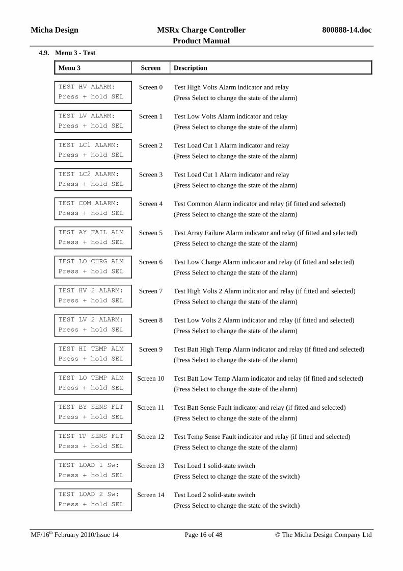
4.9. Menu 3 - Test
Menu 3 Screen Description TEST HV ALARM:
Press + hold SEL Screen 0 Test High Volts Alarm indicator and relay
(Press Select to change the state of the alarm) TEST LV ALARM:
Press + hold SEL Screen 1 Test Low Volts Alarm indicator and relay
(Press Select to change the state of the alarm) TEST LC1 ALARM:
Press + hold SEL Screen 2 Test Load Cut 1 Alarm indicator and relay
(Press Select to change the state of the alarm) TEST LC2 ALARM:
Press + hold SEL Screen 3 Test Load Cut 1 Alarm indicator and relay
(Press Select to change the state of the alarm) TEST COM ALARM:
Press + hold SEL Screen 4 Test Common Alarm indicator and relay (if fitted and selected)
(Press Select to change the state of the alarm) TEST AY FAIL ALM
Press + hold SEL Screen 5 Test Array Failure Alarm indicator and relay (if fitted and selected)
(Press Select to change the state of the alarm) TEST LO CHRG ALM
Press + hold SEL Screen 6 Test Low Charge Alarm indicator and relay (if fitted and selected)
(Press Select to change the state of the alarm) TEST HV 2 ALARM:
Press + hold SEL Screen 7 Test High Volts 2 Alarm indicator and relay (if fitted and selected)
(Press Select to change the state of the alarm) TEST LV 2 ALARM:
Press + hold SEL Screen 8 Test Low Volts 2 Alarm indicator and relay (if fitted and selected)
(Press Select to change the state of the alarm) TEST HI TEMP ALM
Press + hold SEL Screen 9 Test Batt High Temp Alarm indicator and relay (if fitted and selected)
(Press Select to change the state of the alarm) TEST LO TEMP ALM
Press + hold SEL Screen 10 Test Batt Low Temp Alarm indicator and relay (if fitted and selected)
(Press Select to change the state of the alarm) TEST BY SENS FLT
Press + hold SEL Screen 11 Test Batt Sense Fault indicator and relay (if fitted and selected)
(Press Select to change the state of the alarm) TEST TP SENS FLT
Press + hold SEL Screen 12 Test Temp Sense Fault indicator and relay (if fitted and selected)
(Press Select to change the state of the alarm) TEST LOAD 1 Sw:
Press + hold SEL Screen 13 Test Load 1 solid-state switch
(Press Select to change the state of the switch) TEST LOAD 2 Sw:
Press + hold SEL Screen 14 Test Load 2 solid-state switch
(Press Select to change the state of the switch)
Micha Design MSRx Charge Controller 800888-14.doc Product Manual
MF/16th February 2010/Issue 14 Page 17 of 48 © The Micha Design Company Ltd
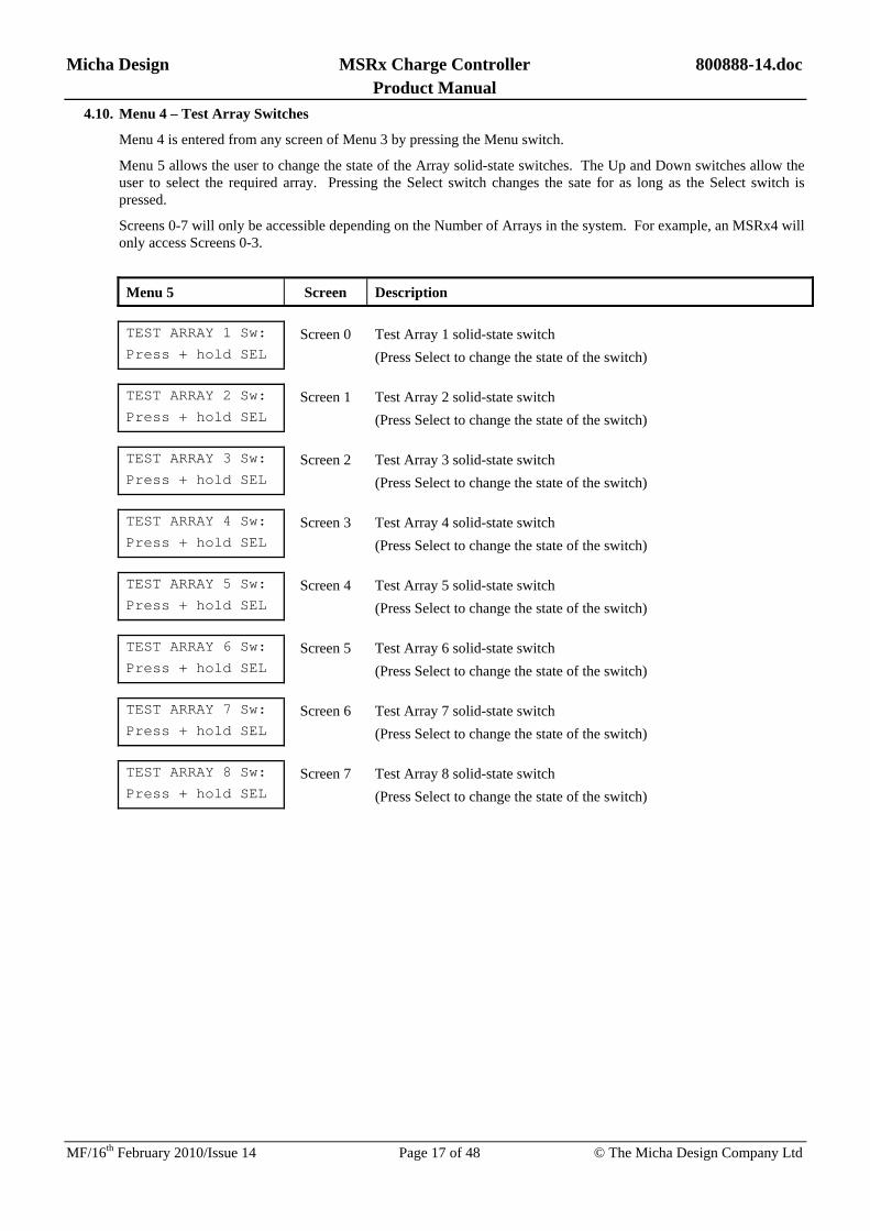
4.10. Menu 4 – Test Array Switches
Menu 4 is entered from any screen of Menu 3 by pressing the Menu switch.
Menu 5 allows the user to change the state of the Array solid-state switches. The Up and Down switches allow the user to select the required array. Pressing the Select switch changes the sate for as long as the Select switch is pressed.
Screens 0-7 will only be accessible depending on the Number of Arrays in the system. For example, an MSRx4 will only access Screens 0-3.
Menu 5 Screen Description TEST ARRAY 1 Sw:
Press + hold SEL Screen 0 Test Array 1 solid-state switch
(Press Select to change the state of the switch) TEST ARRAY 2 Sw:
Press + hold SEL Screen 1 Test Array 2 solid-state switch
(Press Select to change the state of the switch) TEST ARRAY 3 Sw:
Press + hold SEL Screen 2 Test Array 3 solid-state switch
(Press Select to change the state of the switch) TEST ARRAY 4 Sw:
Press + hold SEL Screen 3 Test Array 4 solid-state switch
(Press Select to change the state of the switch) TEST ARRAY 5 Sw:
Press + hold SEL Screen 4 Test Array 5 solid-state switch
(Press Select to change the state of the switch) TEST ARRAY 6 Sw:
Press + hold SEL Screen 5 Test Array 6 solid-state switch
(Press Select to change the state of the switch) TEST ARRAY 7 Sw:
Press + hold SEL Screen 6 Test Array 7 solid-state switch
(Press Select to change the state of the switch) TEST ARRAY 8 Sw:
Press + hold SEL Screen 7 Test Array 8 solid-state switch
(Press Select to change the state of the switch)

Micha Design MSRx Charge Controller 800888-14.doc Product Manual
MF/16th February 2010/Issue 14 Page 18 of 48 © The Micha Design Company Ltd
4.11. Menu 5 – Array Voltages
Menu 5 is entered from any screen of Menu 4 by pressing the Menu switch.
Menu 5 allows the user to view the open circuit array voltages. The Up and Down switches allow the user to select the required array.
NOTE: In order to measure the open-circuit voltage on any Array, the MSRx unit needs to turn off the Array solid-state switch to disconnect it from the battery. When the Select switch is pressed, the Array Switch is turned off and the voltage measured.
Screens 0-7 will only be accessible depending on the Number of Arrays in the system. For example, an MSRx4 will only access Screens 0-3.
NOTE: An array voltage will be measured correctly only when there is an array module connected to the array input, and the array input MCB is turned on.
Menu 5 Screen Description SHOW ARRAY 1 V:
Press + hold SEL Screen 0 Show Array 1 open-circuit array voltage
(Press Select to show the voltage) SHOW ARRAY 2 V:
Press + hold SEL Screen 1 Show Array 2 open-circuit array voltage
(Press Select to show the voltage) SHOW ARRAY 3 V:
Press + hold SEL Screen 2 Show Array 3 open-circuit array voltage
(Press Select to show the voltage) SHOW ARRAY 4 V:
Press + hold SEL Screen 3 Show Array 4 open-circuit array voltage
(Press Select to show the voltage) SHOW ARRAY 5 V:
Press + hold SEL Screen 4 Show Array 5 open-circuit array voltage
(Press Select to show the voltage) SHOW ARRAY 6 V:
Press + hold SEL Screen 5 Show Array 6 open-circuit array voltage
(Press Select to show the voltage) SHOW ARRAY 7 V:
Press + hold SEL Screen 6 Show Array 7 open-circuit array voltage
(Press Select to show the voltage) SHOW ARRAY 8 V:
Press + hold SEL Screen 7 Show Array 8 open-circuit array voltage
(Press Select to show the voltage)

Micha Design MSRx Charge Controller 800888-14.doc Product Manual
MF/16th February 2010/Issue 14 Page 19 of 48 © The Micha Design Company Ltd
4.12. Menu 6 – Array Currents
Menu 6 is entered from any screen of Menu 4 by pressing the Menu switch.
Menu 6 allows the user to view the Array current flowing from each array. The Up and Down switches allow the user to select the required array.
NOTE: In order to measure an individual Array current, the MSRx unit will turn on that individual Array Switch to connect it to the Battery and it will turn off all the other Array Switches, which will disconnect them from the Battery. This will happen for 5 seconds following the pressing of the Select switch. The user will be unable to move up and down the Menu during the 5 second period.
Screens 0-7 will only be accessible depending on the Number of Arrays in the system. For example, an MSRx4 will only access Screens 0-3.
Menu 6 Screen Description SHOW ARRAY 1 I:
Press + hold SEL Screen 0 Show Array 1 current
(Press Select to show the current) SHOW ARRAY 2 I:
Press + hold SEL Screen 1 Show Array 2 current
(Press Select to show the current) SHOW ARRAY 3 I:
Press + hold SEL Screen 2 Show Array 3 current
(Press Select to show the current) SHOW ARRAY 4 I:
Press + hold SEL Screen 3 Show Array 4 current
(Press Select to show the current) SHOW ARRAY 5 I:
Press + hold SEL Screen 4 Show Array 5 current
(Press Select to show the current) SHOW ARRAY 6 I:
Press + hold SEL Screen 5 Show Array 6 current
(Press Select to show the current) SHOW ARRAY 7 I:
Press + hold SEL Screen 6 Show Array 7 current
(Press Select to show the current) SHOW ARRAY 8 I:
Press + hold SEL Screen 7 Show Array 8 current
(Press Select to show the current)

Micha Design MSRx Charge Controller 800888-14.doc Product Manual
MF/16th February 2010/Issue 14 Page 20 of 48 © The Micha Design Company Ltd
4.13. Change Settings Menus
The Change Settings Menus A-D (see next few pages) exist to allow an authorised user to change the settings of the unit in the field. The Change Settings Menus can only be entered by doing the following:
MSRx Steel Enclosure Unit: Insert the jumper link on LK1 (on the MSRx PSU/Load PCB Assembly) in the Disable position, hold the Menu, Up and Down switches pressed and then press the Select switch.
MSRx 19” Rack Unit: Ensure the front panel keyswitch is turned to “Keypad Enable”. Hold the Menu, Up and Down switches pressed and then press the Select switch.
4.13.1. Range of Settings
The Change Settings Menu allows the user to change the settings as shown in the overview diagram on the next page and listed on the following pages.
4.13.2. Changing Settings
The Menu, Up and Down switches are used to select the setting to be changed. The Select switch is pressed and the value will flash. The Up and Down switches are used to vary the value. The Select switch is pressed and the value will stop flashing. The Menu, Up and Down switches can be used again to select a setting to be changed or to navigate to the “Accept?” screen.
4.13.3. Accepting Changes to Settings
In order to remember the new settings, the user must navigate to the “Accept ?” screen and press the Select switch. The unit will not remember any changes to settings unless they are accepted by using this screen.
4.13.4. Default Settings
The Change Settings Menu allows the user to reset most of the settings back to default preset battery settings. Refer to Section 4.19 for the range available.
4.13.5. Exiting the Change Settings Menus
Pressing the Menu switch at one of the Menu D screens, will exit the Change Settings Menus without remembering any changes. The user is taken back to Menu 0.
Pressing the Select switch at the Accept screen (Screen 0) will exit the Change Settings Menus and remember any changes. The user is taken back to Menu 0.
Pressing the Select switch at any of the Default screens will exit the Change Settings Menus and the new default values will be programmed into the unit. The user is taken back to Menu 0.

Micha Design MSRx Charge Controller 800888-14.doc Product Manual
MF/16th February 2010/Issue 14 Page 21 of 48 © The Micha Design Company Ltd
4.13.6. Changing Settings Menus - Diagram
Men
u A
CH
AN
GE
SE
TTIN
GS
:B
oost
V: 2
9.4
CH
AN
GE
SE
TTIN
GS
:LC
1 D
elay
: 60s
ec
CH
AN
GE
SE
TTIN
GS
:LC
2 D
elay
: 60s
ec
CH
AN
GE
SE
TTIN
GS
:M
SR
x: S
tand
ard
CH
AN
GE
SE
TTIN
GS
:Fl
oat V
: 27.
6
CH
AN
GE
SE
TTIN
GS
:R
st to
Bst
: 26.
4
CH
AN
GE
SE
TTIN
GS
:H
i V S
et V
: 30.
0
CH
AN
GE
SE
TTIN
GS
:H
i V R
st V
: 27.
6
CH
AN
GE
SE
TTIN
GS
:Lo
V S
et V
: 23.
4
CH
AN
GE
SE
TTIN
GS
:Lo
V R
st V
: 27.
6
CH
AN
GE
SE
TTIN
GS
:LC
1 S
et V
: 22.
8
CH
AN
GE
SE
TTIN
GS
:LC
1 R
st V
: 25.
8
CH
AN
GE
SE
TTIN
GS
:LC
2 S
et V
: 22.
2
CH
AN
GE
SE
TTIN
GS
:LC
2 R
st V
: 25.
2
CH
AN
GE
SE
TTIN
GS
:E
qual
isat
ion
30m
CH
AN
GE
SE
TTIN
GS
:A
Y4
Fail
= O
ff
CH
AN
GE
SE
TTIN
GS
:A
Y3
Fail
= O
ff
Ente
r Cha
nge
Setti
ngs
Men
uby
inse
rting
the
Dis
able
link
and
pres
sing
the
Sele
ct s
witc
hw
ith M
enu,
Up
and
Dow
nsw
itche
s al
l dep
ress
ed.
Up
Dow
n
Up
Dow
n
Up
Dow
n
Up
Dow
n
Up
Dow
n
Up
Dow
n
Up
Dow
n
Up
Dow
n
Up
Dow
n
Up
Dow
n
Up
Dow
n
Up
Dow
n
Up
Dow
n
Up
Dow
n
Up
Dow
n
Up
Dow
n
Up
Dow
n
Up
Dow
n
CH
AN
GE
SE
TTIN
GS
:A
Y F
ail T
ime
48H
CH
AN
GE
SE
TTIN
GS
:A
Y2
Fail
= O
ff
CH
AN
GE
SE
TTIN
GS
:A
Y5
Fail
= O
ff
CH
AN
GE
SE
TTIN
GS
:A
Y6
Fail
= O
ff
Up
Dow
n
Men
uM
enu
Men
u B
CH
AN
GE
SE
TTIN
GS
:H
V 2
Set
V:
30.0
CH
AN
GE
SE
TTIN
GS
:H
V 2
Alm
Fn:
Off
Up
Dow
n
Up
Dow
n
Up
Dow
n
CH
AN
GE
SE
TTIN
GS
:H
V 2
Rst
V:
27.6
CH
AN
GE
SE
TTIN
GS
:LV
2 A
lm F
n: O
ff
Men
u C
CH
AN
GE
SE
TTIN
GS
:A
Y7
Fail
= O
ff
CH
AN
GE
SE
TTIN
GS
:A
Y8
Fail
= O
ff
Up
Dow
n
Up
Dow
n
CH
AN
GE
SE
TTIN
GS
:Te
mp
Nul
l: 2
0C
CH
AN
GE
SE
TTIN
GS
:Te
mp
Rat
e: -5
.0m
VU
pD
own
CH
AN
GE
SE
TTIN
GS
:LC
1 &
LC
2: D
IFF
Up
Dow
n
CH
AN
GE
SE
TTIN
GS
:A
Y1
Fail
= O
ff
Up
Dow
n
CH
AN
GE
SE
TTIN
GS
:Ld
Shu
nt =
60A
CH
AN
GE
SE
TTIN
GS
:Lo
w C
hrg
Day
s:00
Up
Dow
n
CH
AN
GE
SE
TTIN
GS
:N
o of
Arra
ys: 4
Up
Dow
n
Up
Dow
n
Up
Dow
n
Men
u
CH
AN
GE
SE
TTIN
GS
:R
eg D
is D
ly: 0
1s
CH
AN
GE
SE
TTIN
GS
:R
eg C
on D
ly: 0
5sU
pD
own
Up
Dow
n
Up
Dow
n
CH
AN
GE
SE
TTIN
GS
:R
eg M
in O
T:01
:00
CH
AN
GE
SE
TTIN
GS
:Te
st M
ode:
Off
Men
u D
Men
u
Up
Dow
n
Up
Dow
n
CH
AN
GE
SE
TTIN
GS
:LV
2 S
et V
: 23
.4
Up
Dow
n
Up
Dow
n
Up
Dow
n
CH
AN
GE
SE
TTIN
GS
:LV
2 R
st V
: 27
.6
CH
AN
GE
SE
TTIN
GS
:B
Tmp
Alm
Fn:
Off
Up
Dow
n
Up
Dow
n
Up
Dow
n
Up
Dow
n
Up
Dow
n
Up
Dow
n
CH
AN
GE
SE
TTIN
GS
:S
tdR
1: H
i V A
larm
CH
AN
GE
SE
TTIN
GS
:S
tdR
2: L
o V
Ala
rm
CH
AN
GE
SE
TTIN
GS
:S
tdR
5: C
om A
larm
CH
AN
GE
SE
TTIN
GS
:S
tdR
6: A
y Fa
il A
l
CH
AN
GE
SE
TTIN
GS
:B
att H
i Tem
p: 5
0
CH
AN
GE
SE
TTIN
GS
:B
att L
o Te
mp:
00
4-20
mA
Mod
ule
1O
utpu
t:
X
XU
pD
own
Up
Dow
n
4-20
mA
Mod
1: X
X4m
A =
> xx
xx
4-20
mA
Mod
1: X
X20
mA
=>
xxxx
Up
Dow
n
CH
AN
GE
SE
TTIN
GS
:Ld
Cut
on
HV
: Off
Up
Dow
n
CH
AN
GE
SE
TTIN
GS
:A
yV S
ampl
e:08
:00
Up
Dow
n
CH
AN
GE
SE
TTIN
GS
:A
y S
hunt
1: 1
50A
Up
Dow
n
CH
AN
GE
SE
TTIN
GS
:A
y S
hunt
2:
0A
Rel
ay M
odul
e: 1
Rly
1: N
ot U
sed
Up
Dow
n
Rel
ay M
odul
e: 1
Rly
2: N
ot U
sed
Rel
ay M
odul
e: 1
Rly
3: N
ot U
sed
Rel
ay M
odul
e: 1
Rly
4: N
ot U
sed
Up
Dow
n
Up
Dow
n
Up
Dow
n
RS
232
Mod
ule:
Uni
t No:
1
Dat
a Lo
g M
odul
e:S
elec
t: D
isab
le
Up
Dow
n
Up
Dow
n
Up
Dow
n
Up
Dow
n
Up
Dow
n
Up
Dow
n
Up
Dow
n
Up
Dow
n
Up
Dow
n
Up
Dow
n
Rel
ay M
odul
e: 2
Rly
1: N
ot U
sed
Up
Dow
n
Rel
ay M
odul
e: 2
Rly
2: N
ot U
sed
Rel
ay M
odul
e: 2
Rly
3: N
ot U
sed
Rel
ay M
odul
e: 2
Rly
4: N
ot U
sed
Up
Dow
n
Up
Dow
n
Up
Dow
n
Rel
ay M
odul
e: 3
Rly
1: N
ot U
sed
Up
Dow
n
Rel
ay M
odul
e: 3
Rly
2: N
ot U
sed
Rel
ay M
odul
e: 3
Rly
3: N
ot U
sed
Rel
ay M
odul
e: 3
Rly
4: N
ot U
sed
Up
Dow
n
Up
Dow
n
Up
Dow
n
Rel
ay M
odul
e: 4
Rly
1: N
ot U
sed
Up
Dow
n
Rel
ay M
odul
e: 4
Rly
2: N
ot U
sed
Rel
ay M
odul
e: 4
Rly
3: N
ot U
sed
Rel
ay M
odul
e: 4
Rly
4: N
ot U
sed
Up
Dow
n
Up
Dow
n
Up
Dow
n
Up
Dow
n
CH
AN
GE
SE
TTIN
GS
:R
eg H
yst =
0.3
0V
Up
Dow
n
Up
Dow
n
Up
Dow
n
Men
u E
Men
u
Set
Exp
Mod
ule:
Earth
Lea
kage
>
CH
AN
GE
SE
TTIN
GS
:S
tdR
3: L
C1
Ala
rm
CH
AN
GE
SE
TTIN
GS
:S
tdR
4: L
C2
Ala
rm
Set
Exp
Mod
ule:
4-20
mA
Out
puts
>
Set
Exp
Mod
ule:
Rel
ay O
utpu
ts >
Set
Exp
Mod
ule:
RS2
32 P
ort/L
og >
Earth
Lea
k M
od:
Sel
ect:
Dis
able
Up
Dow
n
Earth
Lea
k M
od:
Alm
Dly
: 60
secs
Aux
An
I/p M
od:1
Sel
ect:
Dis
able
RS
232
Mod
ule:
Sel
ect:
Dis
able
4-20
mA
Mod
ule
2O
utpu
t:
X
X
4-20
mA
Mod
2: X
X4m
A =
> xx
xx
4-20
mA
Mod
2: X
X20
mA
=>
xxxx
4-20
mA
Mod
ule
3O
utpu
t:
X
X
4-20
mA
Mod
3: X
X4m
A =
> xx
xx
4-20
mA
Mod
3: X
X20
mA
=>
xxxx
4-20
mA
Mod
ule
4O
utpu
t:
X
X
4-20
mA
Mod
4: X
X4m
A =
> xx
xx
4-20
mA
Mod
4: X
X20
mA
=>
xxxx
Sele
ct
Sele
ct
Men
u
Sele
ct
Sele
ct
Men
u
Men
u
Men
u
Dat
a Lo
g M
odul
e:Lo
g Pe
r: 30
min
s
Up
Dow
n
Mod
em M
odul
e:S
elec
t: D
isab
le
Up
Dow
n
Dat
a Lo
g M
odul
e:C
lk: H
ours
: 17:
45
Up
Dow
n
Dat
a Lo
g M
odul
e:C
lk: M
ins:
17:
45
Up
Dow
n
Dat
a Lo
g M
odul
e:C
lk: D
ate:
01
Up
Dow
n
Dat
a Lo
g M
odul
e:C
lk: M
onth
: 08
Up
Dow
n
Dat
a Lo
g M
odul
e:C
lk: Y
ear:
2006
Up
Dow
n
Up
Dow
n
Set
Exp
Mod
ule:
Aux
An
Inpu
ts >
CH
AN
GE
SE
TTIN
GS
:1
Fulm
en ->
SE
L
CH
AN
GE
SE
TTIN
GS
:A
ccep
t ? ->
SE
LU
pD
own
Up
Dow
n
CH
AN
GE
SE
TTIN
GS
:2
Ven
ted
-> S
EL
CH
AN
GE
SE
TTIN
GS
:3
VR
LA ->
SE
L
CH
AN
GE
SE
TTIN
GS
:4
Abs
olyt
e >
SE
L
Up
Dow
n
Up
Dow
n
Men
u F
Sub
Men
u L
Men
u
Sele
ct
Sub
Men
u K
Sub
Men
u J
Sub
Men
u I
Sub
Men
u H
Men
u
Men
u
Men
u
Men
u
Men
u
Men
u
Men
u
Men
u
Men
u
Men
u
Men
u
Men
u
Men
u
Men
u
Men
u
Men
u
Men
u
Men
u
Men
u
Men
u
Men
u
Men
u
Men
u
Men
u
Men
u
Men
u
Men
u
Men
u
Men
u
Men
u
Men
u
Men
u
Men
u
Men
u
Men
u
Men
u
Men
u
Men
u
Men
u
Men
u
CH
AN
GE
SE
TTIN
GS
:5
Gel
/OP
zV >
SE
L
Up
Dow
n

Micha Design MSRx Charge Controller 800888-14.doc Product Manual
MF/16th February 2010/Issue 14 Page 22 of 48 © The Micha Design Company Ltd
4.14. Menu A – Change System Settings
Menu A Screen Description
CHANGE SETTINGS:
Boost V: xx.x Screen 0 Boost Regulation Voltage Set-point
CHANGE SETTINGS:
Float V: xx.x Screen 1 Float Regulation Voltage Set-point
CHANGE SETTINGS:
Rst to Bst V:xx.x Screen 2 Reset to Boost Voltage
CHANGE SETTINGS:
Hi V Set V: xx.x Screen 3 High Volts Alarm Trip Voltage Set-point
CHANGE SETTINGS:
Hi V Rst V: xx.x Screen 4 High Volts Alarm Reset Voltage Set-point
CHANGE SETTINGS:
Lo V Set V: xx.x Screen 5 Low Volts Alarm Trip Voltage Set-point
CHANGE SETTINGS:
Lo V Rst V: xx.x Screen 6 Low Volts Alarm Reset Voltage Set-point
CHANGE SETTINGS:
LC1 Set V: xx.x Screen 7 Load Cut 1 Alarm Trip Voltage Set-point
CHANGE SETTINGS:
LC1 Rst V: xx.x Screen 8 Load Cut 1 Alarm Reset Voltage Set-point
CHANGE SETTINGS:
LC1 Set V: xx.x Screen 9 Load Cut 2 Alarm Trip Voltage Set-point
CHANGE SETTINGS:
LC1 Rst V: xx.x Screen 10 Load Cut 2 Alarm Reset Voltage Set-point
CHANGE SETTINGS:
LC1 Delay: xx sec Screen 11 Load Cut 1 Delay Period (5 to 240 seconds)
(Time between the alarm being activated and the load being cut)
CHANGE SETTINGS:
LC2 Delay: xx sec Screen 12 Load Cut 2 Delay Period (5 to 240 seconds)
(Time between the alarm being activated and the load being cut)
CHANGE SETTINGS:
Equalisation:xx m Screen 13 Equalisation Period (1 to 90 minutes)
CHANGE SETTINGS:
MSRx: Standard Screen 14 Type of Unit: Standard Unit or 19” Rack Unit
Standard = Painted, Stainless, GRP Enclosure
CHANGE SETTINGS:
No of Arrays: x Screen 15 Number of Arrays in the MSRx unit
(MSRx2 = 2, MSRx4 = 4, MSRx6 = 6, MSRx8 = 8)

Micha Design MSRx Charge Controller 800888-14.doc Product Manual
MF/16th February 2010/Issue 14 Page 23 of 48 © The Micha Design Company Ltd
4.15. Menu B – Change System Settings
Menu B Screen Description
CHANGE SETTINGS:
Temp Null: xxC Screen 0 Temperature Compensation Null Temperature
CHANGE SETTINGS:
Temp Rate:-x.xmV Screen 1 Temperature Compensation Rate
CHANGE SETTINGS:
Ld Shunt = xxxA Screen 2 Load Shunt value: 60A / 100A / 150A
(This must be set for the shunt value fitted to the unit)
CHANGE SETTINGS:
LC1 & LC2: DIFF Screen 3 Load Cut 1 & Load Cut 2: DIFF (Different) or SAME (Same)
(The two load cuts can be selected to work together – same)
CHANGE SETTINGS:
Low Chrg Days:00 Screen 4 Low Charge Days function: This sets the number of consecutive days
the unit must see low charge before activating the low charge alarm.
CHANGE SETTINGS:
AY Fail Time xxH Screen 5 Array Fail Time: This sets the number of hours the unit will monitor
each selected array input for its ready-to-charge condition
CHANGE SETTINGS:
AY1 Fail = OFF Screen 6 Array 1 Failure select: OFF or ON
To select the array failure on this array – set to ON
CHANGE SETTINGS:
AY2 Fail = OFF Screen 7 Array 2 Failure select: OFF or ON
To select the array failure on this array – set to ON
CHANGE SETTINGS:
AY3 Fail = OFF Screen 8 Array 3 Failure select: OFF or ON
To select the array failure on this array – set to ON
CHANGE SETTINGS:
AY4 Fail = OFF Screen 9 Array 4 Failure select: OFF or ON
To select the array failure on this array – set to ON
CHANGE SETTINGS:
AY5 Fail = OFF Screen 10 Array 5 Failure select: OFF or ON
To select the array failure on this array – set to ON
CHANGE SETTINGS:
AY6 Fail = OFF Screen 11 Array 6 Failure select: OFF or ON
To select the array failure on this array – set to ON
CHANGE SETTINGS:
AY7 Fail = OFF Screen 12 Array 7 Failure select: OFF or ON
To select the array failure on this array – set to ON
CHANGE SETTINGS:
AY8 Fail = OFF Screen 13 Array 8 Failure select: OFF or ON
To select the array failure on this array – set to ON

Micha Design MSRx Charge Controller 800888-14.doc Product Manual
MF/16th February 2010/Issue 14 Page 24 of 48 © The Micha Design Company Ltd
4.16. Menu C – Change System Settings
Menu C Screen Description
CHANGE SETTINGS:
HV 2 Alm Fn: Off Screen 0 High Volts 2 Alarm Function
Select function On or Off
CHANGE SETTINGS:
HV 2 Set V: xx.x Screen 1 High Volts 2 Alarm Trip Voltage Set-point
CHANGE SETTINGS:
HV 2 Rst V: xx.x Screen 2 High Volts 2 Alarm Reset Voltage Set-point
CHANGE SETTINGS:
LV 2 Alm Fn: Off Screen 3 Low Volts 2 Alarm Function
Select function On or Off
CHANGE SETTINGS:
LV 2 Set V: xx.x Screen 4 Low Volts 2 Alarm Trip Voltage Set-point
CHANGE SETTINGS:
LV 2 Rst V: xx.x Screen 5 Low Volts 2 Alarm Reset Voltage Set-point
CHANGE SETTINGS:
BTmp Alm Fn: Off Screen 6 Battery Temperature Alarm Function
Select function On or Off
CHANGE SETTINGS:
Batt Hi Temp: xx Screen 7 Battery High Temperature Alarm Set-point
CHANGE SETTINGS:
Batt Lo Temp: xx Screen 8 Battery Low Temperature Alarm Set-point
CHANGE SETTINGS:
StdR1: Hi V Alarm Screen 9 Standard Relay 1 Alarm select: Assign any Alarm function to MSRx
Standard or 19” Rack MSRx Alarm Relay marked “High Volts Alarm”
CHANGE SETTINGS:
StdR2: Lo V Alarm Screen 10 Standard Relay 2 Alarm select: Assign any Alarm function to MSRx
Standard or 19” Rack MSRx Alarm Relay marked “Low Volts Alarm”
CHANGE SETTINGS:
StdR3: LC1 Alarm Screen 11 Standard Relay 3 Alarm select: Assign any Alarm function to MSRx
Standard or 19” Rack MSRx Alarm Relay marked “Load 1 Alarm”
CHANGE SETTINGS:
StdR4: LC2 Alarm Screen 12 Standard Relay 4 Alarm select: Assign any Alarm function to MSRx
Standard or 19” Rack MSRx Alarm Relay marked “Load 2 Alarm”
CHANGE SETTINGS:
StdR5: Com Alarm Screen 13 Standard Relay 5 Alarm select: Assign any Alarm function to MSRx
19” Rack Alarm Relay marked “System Normal” or “Common Alarm”
CHANGE SETTINGS:
StdR6: Ay Fail Al Screen 14 Standard Relay 6 Alarm select: Assign any Alarm function to MSRx
19” Rack Alarm Relay marked “Array Fail Alarm”

Micha Design MSRx Charge Controller 800888-14.doc Product Manual
MF/16th February 2010/Issue 14 Page 25 of 48 © The Micha Design Company Ltd
4.17. Menu D – Change System Settings
Menu D Screen Description
CHANGE SETTINGS:
Reg Con Dly: 05s Screen 0 Regulation Connection Delay: 1-10 seconds (default = 5 seconds)
The delay between arrays connecting during regulation
CHANGE SETTINGS:
Reg Dis Dly: 05s Screen 1 Regulation Disconnection Delay: 1-10 seconds (default = 1 seconds)
The delay between arrays disconnecting during regulation
CHANGE SETTINGS:
Reg Min OT:01:00 Screen 2 Regulation Minimum Off Time: 5 seconds to 20 minutes (default 1 min)
The minimum time each array must stay off during regulation
CHANGE SETTINGS:
Test Mode: Off Screen 3 Test Mode On/Off
To enable or disable the Test Mode (see section 3.1)
CHANGE SETTINGS:
LdCut on HV: Off Screen 4 Load Cut on High Volts On/Off
To enable or disable Load Cut when High Volts Alarm is active
CHANGE SETTINGS:
AyV Sample:08:00 Screen 5 Array Voltage Sample Time: 15 seconds to 16 minutes (default 8 mins)
The time between successive array voltage measurement on the same array when connected to the battery
CHANGE SETTINGS:
Ay Shunt 1: 150A Screen 6 Array Shunt 1 value select: 0A, 150A, 300A, 400A, 500A, 200A, 250A
Standard (default) value for MSRx2/4/6/8 = 150A Must be set to 0A if not being used (0A = shunt not used)
CHANGE SETTINGS:
Ay Shunt 2: 150A Screen 7 Array Shunt 2 value select: 0A, 150A, 300A, 400A, 500A, 200A, 250A
Standard (default) value for MSRx2/4 = 0A / MSRx6/8 = 150A Must be set to 0A if not being used (0A = shunt not used)
CHANGE SETTINGS:
Reg Hyst = 0.30V Screen 8 Regulation Hysteresis:
Part of the Battery Regulation Control – see section 3.4
CHANGE SETTINGS:
LV2 Time: 00:00 Screen 9 Low Voltage 2 Function Time – see Section 3.12
Adjustable from 0 to 5min, 15min, 30min, 1, 2, 4, 6, 8, 10, 12 hours
CHANGE SETTINGS:
Disab: Ays & Lds Screen 10 Disable Link Function: (determines what is disabled when link inserted)
Default = Arrays & Loads disabled when link inserted User can change this to Arrays only, Loads only or None
Micha Design MSRx Charge Controller 800888-14.doc Product Manual
MF/16th February 2010/Issue 14 Page 26 of 48 © The Micha Design Company Ltd
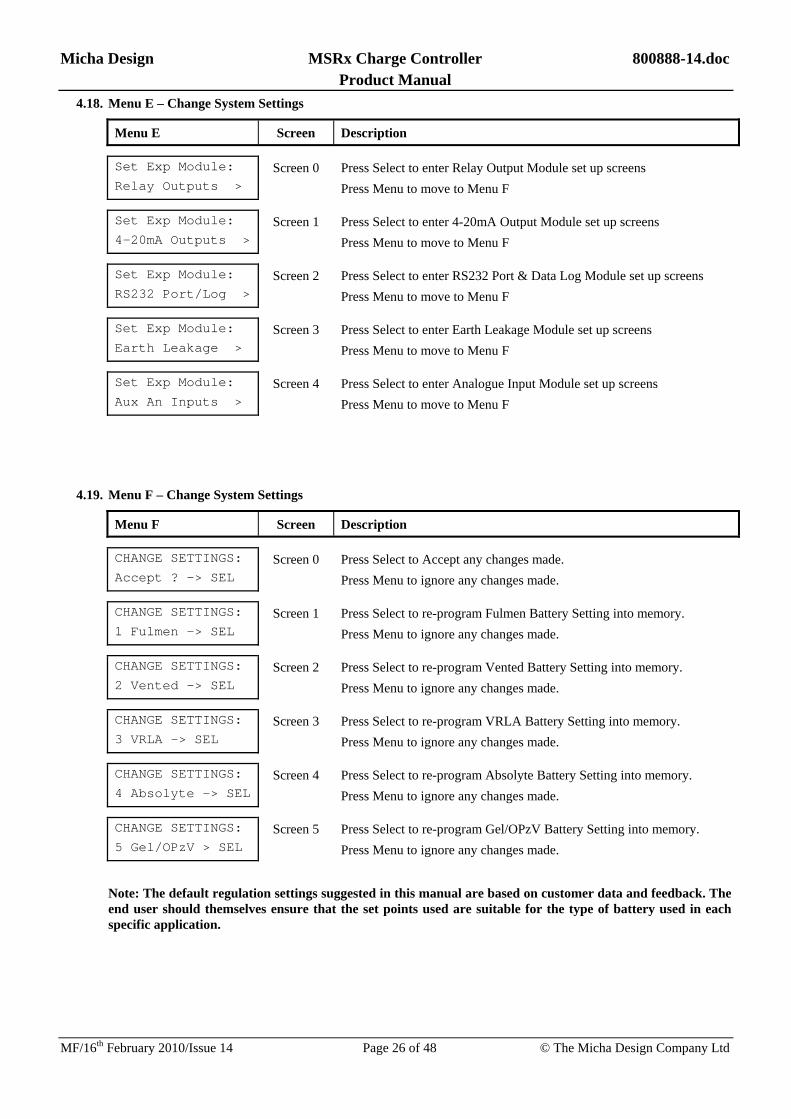
4.18. Menu E – Change System Settings
Menu E Screen Description
Set Exp Module:
Relay Outputs > Screen 0 Press Select to enter Relay Output Module set up screens
Press Menu to move to Menu F
Set Exp Module:
4-20mA Outputs > Screen 1 Press Select to enter 4-20mA Output Module set up screens
Press Menu to move to Menu F
Set Exp Module:
RS232 Port/Log > Screen 2 Press Select to enter RS232 Port & Data Log Module set up screens
Press Menu to move to Menu F
Set Exp Module:
Earth Leakage > Screen 3 Press Select to enter Earth Leakage Module set up screens
Press Menu to move to Menu F
Set Exp Module:
Aux An Inputs > Screen 4 Press Select to enter Analogue Input Module set up screens
Press Menu to move to Menu F
4.19. Menu F – Change System Settings
Menu F Screen Description
CHANGE SETTINGS:
Accept ? -> SEL Screen 0 Press Select to Accept any changes made.
Press Menu to ignore any changes made.
CHANGE SETTINGS:
1 Fulmen -> SEL Screen 1 Press Select to re-program Fulmen Battery Setting into memory.
Press Menu to ignore any changes made.
CHANGE SETTINGS:
2 Vented -> SEL Screen 2 Press Select to re-program Vented Battery Setting into memory.
Press Menu to ignore any changes made.
CHANGE SETTINGS:
3 VRLA -> SEL Screen 3 Press Select to re-program VRLA Battery Setting into memory.
Press Menu to ignore any changes made.
CHANGE SETTINGS:
4 Absolyte -> SEL Screen 4 Press Select to re-program Absolyte Battery Setting into memory.
Press Menu to ignore any changes made.
CHANGE SETTINGS:
5 Gel/OPzV > SEL Screen 5 Press Select to re-program Gel/OPzV Battery Setting into memory.
Press Menu to ignore any changes made.
Note: The default regulation settings suggested in this manual are based on customer data and feedback. The end user should themselves ensure that the set points used are suitable for the type of battery used in each specific application.

Micha Design MSRx Charge Controller 800888-14.doc Product Manual
MF/16th February 2010/Issue 14 Page 27 of 48 © The Micha Design Company Ltd
4.20. MSRx Charge Controller Set-points for FULMEN Batteries (Default Values 1)
Controller Set-points Volts / Cell 12V System 24V System 48V System Boost & Equalise Regulation Voltage 2.45 V 14.70 ± 0.12V 29.40 ± 0.24V 58.80 ± 0.48V
Float Regulation Voltage 2.30 V 13.80 ± 0.12V 27.60 ± 0.24V 55.20 ± 0.48V
Reset to Boost Voltage 2.20 V 13.20 ± 0.12V 26.40 ± 0.24V 52.80 ± 0.48V
High Volts Alarm Trip Voltage 2.50 V 15.00 ± 0.12V 30.00 ± 0.24V 60.00 ± 0.48V
High Volts Alarm Reset Voltage 2.30 V 13.80 ± 0.12V 27.60 ± 0.24V 55.20 ± 0.48V
Low Volts Alarm Trip Voltage 1.95 V 11.70 ± 0.12V 23.40 ± 0.24V 46.80 ± 0.48V
Low Volts Alarm Reset Voltage 2.30 V 13.80 ± 0.12V 27.60 ± 0.24V 55.20 ± 0.48V
Load Cut 1 Alarm Trip Voltage 1.90 V 11.40 ± 0.12V 22.80 ± 0.24V 45.60 ± 0.48V
Load Cut 1 Alarm Reset Voltage 2.15 V 12.90 ± 0.12V 25.80 ± 0.24V 51.60 ± 0.48V
Load Cut 2 Alarm Trip Voltage 1.85 V 11.10 ± 0.12V 22.20 ± 0.24V 44.40 ± 0.48V
Load Cut 2 Alarm Reset Voltage 2.10 V 12.60 ± 0.12V 25.20 ± 0.24V 50.40 ± 0.48V
Load Cut 1 Switch Delay N/A 60 seconds 60 seconds 60 seconds
Load Cut 2 Switch Delay N/A 60 seconds 60 seconds 60 seconds
Equalisation Time N/A 30 minutes 30 minutes 30 minutes
Temp Compensation Null Temp N/A 20 ºC 20 ºC 20 ºC Temp Compensation Rate N/A -5.0mV / cell / ºC -5.0mV / cell / ºC -5.0mV / cell / ºC
4.21. MSRx Charge Controller Set-points for Vented Cell Batteries (Default Values 2)
Controller Set-points Volts / Cell 12V System 24V System 48V System Boost & Equalise Regulation Voltage 2.40 V 14.40 ± 0.12V 28.80 ± 0.24V 57.60 ± 0.48V
Float Regulation Voltage 2.35 V 14.10 ± 0.12V 28.20 ± 0.24V 56.40 ± 0.48V
Reset to Boost Voltage 2.20 V 13.20 ± 0.12V 26.40 ± 0.24V 52.80 ± 0.48V
High Volts Alarm Trip Voltage 2.45 V 14.70 ± 0.12V 29.40 ± 0.24V 58.80 ± 0.48V
High Volts Alarm Reset Voltage 2.40 V 14.40 ± 0.12V 28.80 ± 0.24V 57.60 ± 0.48V
Low Volts Alarm Trip Voltage 1.90 V 11.40 ± 0.12V 22.80 ± 0.24V 45.60 ± 0.48V
Low Volts Alarm Reset Voltage 2.00 V 12.00 ± 0.12V 24.00 ± 0.24V 48.00 ± 0.48V
Load Cut 1 Alarm Trip Voltage 1.85 V 11.10 ± 0.12V 22.20 ± 0.24V 44.40 ± 0.48V
Load Cut 1 Alarm Reset Voltage 2.00 V 12.00 ± 0.12V 24.00 ± 0.24V 48.00 ± 0.48V
Load Cut 2 Alarm Trip Voltage 1.80 V 10.80 ± 0.12V 21.60 ± 0.24V 43.20 ± 0.48V
Load Cut 2 Alarm Reset Voltage 2.00 V 12.00 ± 0.12V 24.00 ± 0.24V 48.00 ± 0.48V
Load Cut 1 Switch Delay N/A 10 seconds 10 seconds 10 seconds
Load Cut 2 Switch Delay N/A 10 seconds 10 seconds 10 seconds
Equalisation Time N/A 30 minutes 30 minutes 30 minutes
Temp Compensation Null Temp N/A 25 ºC 25 ºC 25 ºC
Temp Compensation Rate N/A -5.5mV / cell / ºC -5.5mV / cell / ºC -5.5mV / cell / ºC

Micha Design MSRx Charge Controller 800888-14.doc Product Manual
MF/16th February 2010/Issue 14 Page 28 of 48 © The Micha Design Company Ltd
4.22. MSRx Charge Controller Set-points for VRLA Cell Batteries (Default Values 3)
Controller Set-points Volts / Cell 12V System 24V System 48V System Boost & Equalise Regulation Voltage 2.30 V 13.80 ± 0.12V 27.60 ± 0.24V 55.20 ± 0.48V
Float Regulation Voltage 2.25 V 13.50 ± 0.12V 27.00 ± 0.24V 54.00 ± 0.48V
Reset to Boost Voltage 2.10 V 12.60 ± 0.12V 25.20 ± 0.24V 50.40 ± 0.48V
High Volts Alarm Trip Voltage 2.40 V 14.40 ± 0.12V 28.80 ± 0.24V 57.60 ± 0.48V
High Volts Alarm Reset Voltage 2.35 V 14.10 ± 0.12V 28.20 ± 0.24V 56.40 ± 0.48V
Low Volts Alarm Trip Voltage 1.90 V 11.40 ± 0.12V 22.80 ± 0.24V 45.60 ± 0.48V
Low Volts Alarm Reset Voltage 2.00 V 12.00 ± 0.12V 24.00 ± 0.24V 48.00 ± 0.48V
Load Cut 1 Alarm Trip Voltage 1.85 V 11.10 ± 0.12V 22.20 ± 0.24V 44.40 ± 0.48V
Load Cut 1 Alarm Reset Voltage 2.00 V 12.00 ± 0.12V 24.00 ± 0.24V 48.00 ± 0.48V
Load Cut 2 Alarm Trip Voltage 1.80 V 10.80 ± 0.12V 21.60 ± 0.24V 43.20 ± 0.48V
Load Cut 2 Alarm Reset Voltage 2.00 V 12.00 ± 0.12V 24.00 ± 0.24V 48.00 ± 0.48V
Load Cut 1 Switch Delay N/A 10 seconds 10 seconds 10 seconds
Load Cut 2 Switch Delay N/A 10 seconds 10 seconds 10 seconds
Equalisation Time N/A 30 minutes 30 minutes 30 minutes
Temp Compensation Null Temp N/A 25 ºC 25 ºC 25 ºC
Temp Compensation Rate N/A -3.3mV / cell / ºC -3.3mV / cell / ºC -3.3mV / cell / ºC
4.23. MSRx Charge Controller Set-points for Absolyte Cell Batteries (Default Values 4)
Controller Set-points Volts / Cell 12V System 24V System 48V System Boost & Equalise Regulation Voltage 2.35 V 14.10 ± 0.12V 28.20 ± 0.24V 56.40 ± 0.48V
Float Regulation Voltage 2.25 V 13.50 ± 0.12V 27.00 ± 0.24V 54.00 ± 0.48V
Reset to Boost Voltage 2.10 V 12.60 ± 0.12V 25.20 ± 0.24V 50.40 ± 0.48V
High Volts Alarm Trip Voltage 2.45 V 14.70 ± 0.12V 29.40 ± 0.24V 58.80 ± 0.48V
High Volts Alarm Reset Voltage 2.40 V 14.40 ± 0.12V 28.80 ± 0.24V 57.60 ± 0.48V
Low Volts Alarm Trip Voltage 1.95 V 11.70 ± 0.12V 23.40 ± 0.24V 46.80 ± 0.48V
Low Volts Alarm Reset Voltage 2.30 V 13.80 ± 0.12V 27.60 ± 0.24V 55.20 ± 0.48V
Load Cut 1 Alarm Trip Voltage 1.90 V 11.40 ± 0.12V 22.80 ± 0.24V 45.60 ± 0.48V
Load Cut 1 Alarm Reset Voltage 2.25 V 13.50 ± 0.12V 27.00 ± 0.24V 54.00 ± 0.48V
Load Cut 2 Alarm Trip Voltage 1.85 V 11.10 ± 0.12V 22.20 ± 0.24V 44.40 ± 0.48V
Load Cut 2 Alarm Reset Voltage 2.10 V 12.60 ± 0.12V 25.20 ± 0.24V 50.40 ± 0.48V
Load Cut 1 Switch Delay N/A 10 seconds 10 seconds 10 seconds
Load Cut 2 Switch Delay N/A 10 seconds 10 seconds 10 seconds
Equalisation Time N/A 30 minutes 30 minutes 30 minutes
Temp Compensation Null Temp N/A 25 ºC 25 ºC 25 ºC
Temp Compensation Rate N/A -3.0mV / cell / ºC -3.0mV / cell / ºC -3.0mV / cell / ºC

Micha Design MSRx Charge Controller 800888-14.doc Product Manual
MF/16th February 2010/Issue 14 Page 29 of 48 © The Micha Design Company Ltd
4.24. MSRx Charge Controller Set-points for Gel/OPzV Cell Batteries (Default Values 5)
Controller Set-points Volts / Cell 12V System 24V System 48V System Boost & Equalise Regulation Voltage 2.35 V 14.10 ± 0.12V 28.20 ± 0.24V 56.40 ± 0.48V
Float Regulation Voltage 2.28 V 13.68 ± 0.12V 27.36 ± 0.24V 54.72 ± 0.48V
Reset to Boost Voltage 2.11 V 12.66 ± 0.12V 25.32 ± 0.24V 50.64 ± 0.48V
High Volts Alarm Trip Voltage 2.40 V 14.40 ± 0.12V 28.80 ± 0.24V 57.60 ± 0.48V
High Volts Alarm Reset Voltage 2.15 V 12.90 ± 0.12V 25.80 ± 0.24V 51.60 ± 0.48V
Low Volts Alarm Trip Voltage 1.90 V 11.40 ± 0.12V 22.80 ± 0.24V 45.60 ± 0.48V
Low Volts Alarm Reset Voltage 2.25 V 13.50 ± 0.12V 27.00 ± 0.24V 54.00 ± 0.48V
Load Cut 1 Alarm Trip Voltage 1.85 V 11.10 ± 0.12V 22.20 ± 0.24V 44.40 ± 0.48V
Load Cut 1 Alarm Reset Voltage 2.25 V 13.50 ± 0.12V 27.00 ± 0.24V 54.00 ± 0.48V
Load Cut 2 Alarm Trip Voltage 1.80 V 10.80 ± 0.12V 21.60 ± 0.24V 43.20 ± 0.48V
Load Cut 2 Alarm Reset Voltage 2.05 V 12.30 ± 0.12V 24.60 ± 0.24V 49.20 ± 0.48V
Load Cut 1 Switch Delay N/A 10 seconds 10 seconds 10 seconds
Load Cut 2 Switch Delay N/A 10 seconds 10 seconds 10 seconds
Equalisation Time N/A 30 minutes 30 minutes 30 minutes
Temp Compensation Null Temp N/A 20 ºC 20 ºC 20 ºC
Temp Compensation Rate N/A -5.0mV / cell / ºC -5.0mV / cell / ºC -5.0mV / cell / ºC
Micha Design MSRx Charge Controller 800888-14.doc Product Manual
MF/16th February 2010/Issue 14 Page 30 of 48 © The Micha Design Company Ltd
5. MSRx Optional Features
5.1. 4-Channel Relay Din Rail Module – Micha Part Number: 101589
The 4-Channel Relay Din Rail Module connects to the MSRx Control PCB Assembly Expansion Port to provide four Auxiliary Relay Outputs. See separate datasheet.
5.2. 4-20mA Transducer Type A Din Rail Module – Micha Part Number: 101588
The 4-20mA Transducer Type A Din Rail Module connects to the MSRx Control PCB Assembly Expansion Port to provide one 4-20mA output signal (requires an external power source for the 4-20mA signal). See separate datasheet.
5.3. 4-20mA Transducer Type B Din Rail Module – Micha Part Number: 101597
The 4-20mA Transducer Type B Din Rail Module connects to the MSRx Control PCB Assembly Expansion Port to provide one 4-20mA output signal (an internal dc-dc converter provides power for the 4-20mA signal). See separate datasheet.
5.4. Auxiliary Analogue Input Din Rail Module – Micha Part Number: 101592
The Auxiliary Analogue Input Din Rail Module connects to the MSRx Control PCB Assembly Expansion Port to provide the facility to measure an Auxiliary Voltage (e.g. Load Volts), an Auxiliary Temperature (same sensor as the normal Battery Temperature Sensor) and a Reference Cell (which may be used to measure Solar Irradiation). See separate datasheet.
5.5. RS232 Port Din Rail Module – Micha Part Number: 101595
The RS232 Port Din Rail Module connects to the MSRx Control PCB Assembly Expansion Port to provide the user with an RS232 port which is isolated electrically from the MSRx Charge Controller. A local PC may be plugged into the RS232 port and data may be downloaded from the Controller. Communications protocol can be standard (Micha) or Modbus.
Alternatively, a line or GSM Modem may be connected to this port. See separate datasheet.
5.6. MSRx RS232 Port & Data Log Din Rail Module – Micha Part Number: 101596
The MSRx RS232 Port / Data Log Din Rail Module connects to the MSRx Control PCB Assembly Expansion Port to provide the user with an RS232 port which is isolated electrically from the MSRx Charge Controller. It also provides non-volatile memory which records the operation and status of the charge controller every 15, 30 or 60 minutes. A local PC may be plugged into the RS232 port and data may be downloaded from the Controller and the Data Logger. Communications protocol can be standard (Micha) or Modbus.
Alternatively, a line or GSM Modem may be connected to this port. See separate datasheet.
5.7. Industrial Line or GSM Modems
Industrial line or GSM Modems are available which have been proven to work with the MSRx Charge Controllers. With a modem built into the MSRx Charge Controller, the user may dial up from a remote location using a PC and modem and communicate with the MSRx Charge Controller.
The unit can be set to initialise the modem each time the MSRx Controller powers up.
5.8. MSRx Communications Software
The MSRx Communications Software runs within Microsoft Excel and provides a graphical user interface (GUI) with which to communicate with the MSRx Charge Controller. All the downloaded data from the MSRx Charge Controller is presented to the user and the downloaded data may be saved as a file to the hard disk of the PC.
5.9. MSRx Battery Fuse Assembly – Micha Part Number: 400792
An optional MSRx Battery Fuse Assembly (110 x 30mm) is available for use within the MSRx Charge Controllers. The rating of the fuse will be related to the charging current of the system:
MSRx2 – 80A fuse, MSRx4 – 160A fuse, MSRx6 – 250A fuse, MSRx8 – 325A fuse.

Micha Design MSRx Charge Controller 800888-14.doc Product Manual
MF/16th February 2010/Issue 14 Page 31 of 48 © The Micha Design Company Ltd
5.10. High Current Load Output (>25A)
The MSRx Charge Controller can supply two loads at up to 25A continuous or 50A surge for 2 seconds. It is possible to wire the two load outputs in parallel to increase the current of the resulting one load output to 50A continuous or 80A surge for 2 seconds.
If the two load outputs are wired in parallel, then the Load Cut 1 and Load Cut 2 Alarm levels must be set to the same value. This is done by navigating to the Change Settings Menu B (see section 0) and changing the function from “LC1 & LC2: DIFF” to “LC1 & LC2: SAME” which will force the Load Cut 2 setting to be the same as whatever the Load Cut 1 setting is. By doing this the two load outputs will switch together as one load output.
If a particular application requires a continuous load of greater than 50A or a surge current of greater than 80A then an optional High Current Load Output can be fitted. This consists of a high current MOSFET which is mechanically fixed to the unit mounting plate to provide thermal relief. For each high current MOSFET fitted, the load current can be increased to 30A continuous or 100A surge for 2 seconds. A maximum of two devices can be fitted and wired individually to provide two loads (each 30A continuous, 100A surge) or wired in parallel to provide one load (60A continuous, 200A surge for 2 seconds).
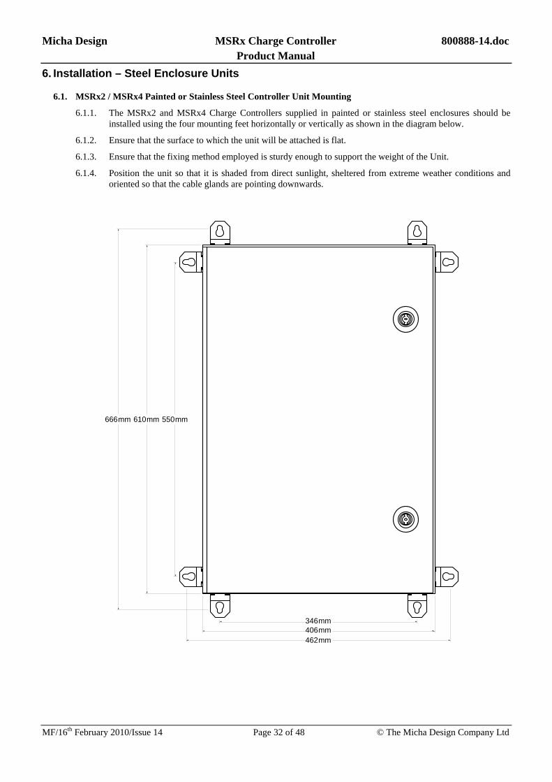
Micha Design MSRx Charge Controller 800888-14.doc Product Manual
MF/16th February 2010/Issue 14 Page 32 of 48 © The Micha Design Company Ltd
6. Installation – Steel Enclosure Units
6.1. MSRx2 / MSRx4 Painted or Stainless Steel Controller Unit Mounting
6.1.1. The MSRx2 and MSRx4 Charge Controllers supplied in painted or stainless steel enclosures should be installed using the four mounting feet horizontally or vertically as shown in the diagram below.
6.1.2. Ensure that the surface to which the unit will be attached is flat.
6.1.3. Ensure that the fixing method employed is sturdy enough to support the weight of the Unit.
6.1.4. Position the unit so that it is shaded from direct sunlight, sheltered from extreme weather conditions and oriented so that the cable glands are pointing downwards.
346mm
550mm
406mm462mm
610mm666mm

Micha Design MSRx Charge Controller 800888-14.doc Product Manual
MF/16th February 2010/Issue 14 Page 33 of 48 © The Micha Design Company Ltd
6.2. MSRx6 / MSRx8 Painted or Stainless Steel Controller Unit Mounting
6.2.1. The MSRx6 and MSRx8 Charge Controllers supplied in painted or stainless steel enclosures should be installed using the four mounting feet horizontally or vertically as shown in the diagram below.
6.2.2. Ensure that the surface to which the unit will be attached is flat.
6.2.3. Ensure that the fixing method employed is sturdy enough to support the weight of the Unit.
6.2.4. Position the unit so that it is shaded from direct sunlight, sheltered from extreme weather conditions and oriented so that the cable glands are pointing downwards.
550mm610mm666mm
550mm610mm666mm

Micha Design MSRx Charge Controller 800888-14.doc Product Manual
MF/16th February 2010/Issue 14 Page 34 of 48 © The Micha Design Company Ltd
6.3. MSRx Painted or Stainless Steel Controller Unit Electrical Connections
COMMON POSITIVE SYSTEM ONLY
CAUTION: SOLAR MODULES AND BATTERIES CAN HAVE POTENTIALLY LETHAL VOLTAGES PRESENT AT THEIR TERMINALS AND PRESENT AN ENERGY HAZARD.
Ensure the Jumper Link LK1 on the MSRx PSU/Load PCB Assembly is fitted in the DISABLE position.
WARNING - RISK OF EXPLOSION:
The battery cable MUST be connected to the MSRx Control Unit BEFORE connecting to the battery
Make the electrical connections in the order shown in the following table:
COMMON POSITIVE SYSTEM ONLY
Connection 1st Location To Connection 2nd Location
BATT COM (+VE) MSRx Control Unit Battery Positive Terminal Battery
BATT LIVE (–VE) MSRx Control Unit Battery Negative Terminal Battery
Battery Sense BS+ MSRx PSU/Load PCB Battery Positive Terminal Battery
Battery Sense BS- MSRx PSU/Load PCB Battery Negative Terminal Battery
ARRAY 1-8 COM MSRx Control Unit Array Positive Terminal Array 1-8 Module
ARRAY 1-8 LIVE MSRx Control Unit Array Negative Terminal Array 1-8 Module
Load Positive Terminal Load 1 LOAD 1 COM MSRx Control Unit
Load Negative Terminal Load 1 LOAD 1 LIVE MSRx Control Unit
Load Positive Terminal Load 2 LOAD 2 COM MSRx Control Unit
Load Negative Terminal Load 2 LOAD 2 LIVE MSRx Control Unit
Red or White wire MSRx Temperature Sensor TEMP SENSE TS+ MSRx PSU/Load PCB
Black or Blue wire MSRx Temperature Sensor TEMP SENSE TS- MSRx PSU/Load PCB
High Volts Alarm Relay MSRx PSU/Load PCB Input Terminals Telemetry System
Low Volts Alarm Relay MSRx PSU/Load PCB Input Terminals Telemetry System
Load Cut 1 Alarm Relay MSRx PSU/Load PCB Input Terminals Telemetry System
Load Cut 2 Alarm Relay MSRx PSU/Load PCB Input Terminals Telemetry System

Micha Design MSRx Charge Controller 800888-14.doc Product Manual
MF/16th February 2010/Issue 14 Page 35 of 48 © The Micha Design Company Ltd
6.4. MSRx Painted or Stainless Steel Controller Unit Electrical Connections
COMMON NEGATIVE SYSTEM ONLY
CAUTION: SOLAR MODULES AND BATTERIES CAN HAVE POTENTIALLY LETHAL VOLTAGES PRESENT AT THEIR TERMINALS AND PRESENT AN ENERGY HAZARD.
Ensure the Jumper Link LK1 on the MSRx PSU/Load PCB Assembly is fitted in the DISABLE position.
WARNING - RISK OF EXPLOSION:
The battery cable MUST be connected to the MSRx Control Unit BEFORE connecting to the battery
Make the electrical connections in the order shown in the following table:
COMMON NEGATIVE SYSTEM ONLY
Connection 1st Location To Connection 2nd Location
BATT COM (-VE) MSRx Control Unit Battery Negative Terminal Battery
BATT LIVE (+VE) MSRx Control Unit Battery Positive Terminal Battery
Battery Sense BS+ MSRx PSU/Load PCB Battery Positive Terminal Battery
Battery Sense BS- MSRx PSU/Load PCB Battery Negative Terminal Battery
ARRAY 1-8 COM MSRx Control Unit Array Negative Terminal Array 1-8 Module
ARRAY 1-8 LIVE MSRx Control Unit Array Positive Terminal Array 1-8 Module
Load Negative Terminal Load 1 LOAD 1 COM MSRx Control Unit
Load Positive Terminal Load 1 LOAD 1 LIVE MSRx Control Unit
Load Negative Terminal Load 2 LOAD 2 COM MSRx Control Unit
Load Positive Terminal Load 2 LOAD 2 LIVE MSRx Control Unit
Red or White wire MSRx Temperature Sensor TEMP SENSE TS+ MSRx PSU/Load PCB
Black or Blue wire MSRx Temperature Sensor TEMP SENSE TS- MSRx PSU/Load PCB
High Volts Alarm Relay MSRx PSU/Load PCB Input Terminals Telemetry System
Low Volts Alarm Relay MSRx PSU/Load PCB Input Terminals Telemetry System
Load Cut 1 Alarm Relay MSRx PSU/Load PCB Input Terminals Telemetry System
Load Cut 2 Alarm Relay MSRx PSU/Load PCB Input Terminals Telemetry System

Micha Design MSRx Charge Controller 800888-14.doc Product Manual
MF/16th February 2010/Issue 14 Page 36 of 48 © The Micha Design Company Ltd
6.5. MSRx Charge Controller Enable
To enable the MSRx Charge Controller, ensure Jumper Link LK1 on the MSRx PSU/Load PCB Assembly is fitted in the ENABLE position.
6.6. MSRx Charge Controller MCBs
Ensure the Array MCBs (if fitted) are set to their ON positions to allow the arrays to charge the battery.
Ensure the Load MCBs (if fitted) are set to their ON positions to allow the battery to supply current to the load.
6.7. Battery Temperature
To ensure the Battery Temperature Compensation is as accurate as possible, proceed with the following instructions after the temperature of the batteries has stabilised:
Using the user switches (Menu, Up, Down and Select), navigate to the Battery Temperature screen (Menu 1, Screen 1). Use a small flat screwdriver to adjust the potentiometer VR1 on the MSRx PSU/Load PCB Assembly so that the temperature shown on display is the same as the actual temperature as measured at the battery with a calibrated temperature meter.

Micha Design MSRx Charge Controller 800888-14.doc Product Manual
MF/16th February 2010/Issue 14 Page 37 of 48 © The Micha Design Company Ltd
7. Installation – 19” Rack Units
7.1. MSRx2 / MSRx4 19” Rack Controller Unit Mounting
7.1.1. The MSRx2 and MSRx4 19” Rack Charge Controllers are designed to be fitted to a 19” Rack Frame and are 4U high (177mm). The units should be fitted such that they are supported by horizontal shelves and not by the front panel fixing holes.
7.1.2. The drawing below is a General Arrangement of an MSRx4 19” Rack Charge Controller.
MENU
UP
DOWN
SELECT
MSRx Charge Controller
101 102 103 104 105 106 107 108 109 110 111 112
AR
RA
Y 1
CO
M
BA
TTER
Y C
OM
GEN
. CO
M
GEN
. LIV
E
BA
TTER
Y LI
VE
AR
RA
Y 1
LIVE
AR
RA
Y 2
CO
M
AR
RA
Y 2
LIVE
AR
RA
Y 3
CO
M
AR
RA
Y 3
LIVE
AR
RA
Y 4
CO
M
AR
RA
Y 4
LIVE
MSR
x4 N
EGAT
IVE
EAR
TH 5
00 X
XX
CONTROLLER INFORMATION
TB4
SK1TB3TB2TB1
J1 J2
+VE
-VE
LOAD
SHUNT
SKT9WAY15 9
18
15WAY SKT
BATTERY
TS+
TS-
TEMP
SENSOR
SCR
BS-
BS+
SENSE
+VE
-VE
REMOTE
DISABLE
ALARMS
1 1
MSRx 19" RACK CONNECTION PCB ASSEMBLY 400 769
RS232
MSRx 19" RACK CONTROLLER
MSRx2 MSRx4
12V 24V
PE NE
SERIAL NO. TESTED
48V
SK2
ARRAYS
1 2 3 4
LOADS
1 2
KEYPADENABLE
KEYPADDISABLE
STATUS
BOOSTEQUAL
FLOATNIGHT
LOA
D 1
LIV
E
LOA
D 1
CO
M
LOA
D 2
LIV
E
LOA
D 2
CO
M
113 114 115 116
EAR
TH

Micha Design MSRx Charge Controller 800888-14.doc Product Manual
MF/16th February 2010/Issue 14 Page 38 of 48 © The Micha Design Company Ltd
7.2. MSRx6 / MSRx8 19” Rack Controller Unit Mounting
7.2.1. The MSRx6 and MSRx8 19” Rack Charge Controllers are designed to be fitted to a 19” Rack Frame and are 8U high (355mm). The units should be fitted such that they are supported by horizontal shelves and not by the front panel fixing holes.
7.2.2. The drawing below is a General Arrangement of an MSRx8 19” Rack Charge Controller.
MENU
UP
DOWN
SELECT
MSRx Charge Controller
CONTROLLER INFORMATIONARRAYS
1 2 3 4
LOADS
1 2
KEYPADENABLE
KEYPADDISABLE
STATUS
BOOST
EQUALFLOAT
NIGHT
ARRAYS
5 6 7 8
202205 206 207 208 209 210 211 212
AR
RA
Y 5
CO
M
AR
RA
Y 5
LIVE
AR
RA
Y 6
CO
M
AR
RA
Y 6
LIVE
AR
RA
Y 7
CO
M
AR
RA
Y 7
LIVE
AR
RA
Y 8
CO
M
AR
RA
Y 8
LIVE
101 102 103 104 105 106 107 108 109 110 111 112
AR
RA
Y 1
CO
M
BA
TTER
Y C
OM
GEN
. CO
M
GEN
. LIV
E
BA
TTER
Y LI
VE
AR
RA
Y 1
LIVE
AR
RA
Y 2
CO
M
AR
RA
Y 2
LIVE
AR
RA
Y 3
CO
M
AR
RA
Y 3
LIVE
AR
RA
Y 4
CO
M
AR
RA
Y 4
LIVE
MSRx
8 NE T
ERMI
NAL L
ABEL
1 50
0 930
TB4
SK1TB3TB2TB1
J1 J2
+VE
-VE
LOAD
SHUNT
SKT9WAY15 9
18
15WAY SKT
BATTERY
TS+
TS-
TEMP
SENSOR
SCR
BS-
BS+
SENSE
+VE
-VE
REMOTE
DISABLE
ALARMS
1 1
MSRx 19" RACK CONNECTION PCB ASSEMBLY 400 769
RS232
MSRx 19" RACK CONTROLLER
MSRx2 MSRx4
12V 24V
PE NE
SERIAL NO. TESTED
48V
SK2
LOA
D 1
LIV
E
LOA
D 1
CO
M
LOA
D 2
LIV
E
LOA
D 2
CO
M
113 114 115 116
EAR
TH
201
BATTERYLIVE
BATTERYCOMM
SR
x8 N
E T
ER
MIN
AL
LA
BE
L 2
50
0 9
31
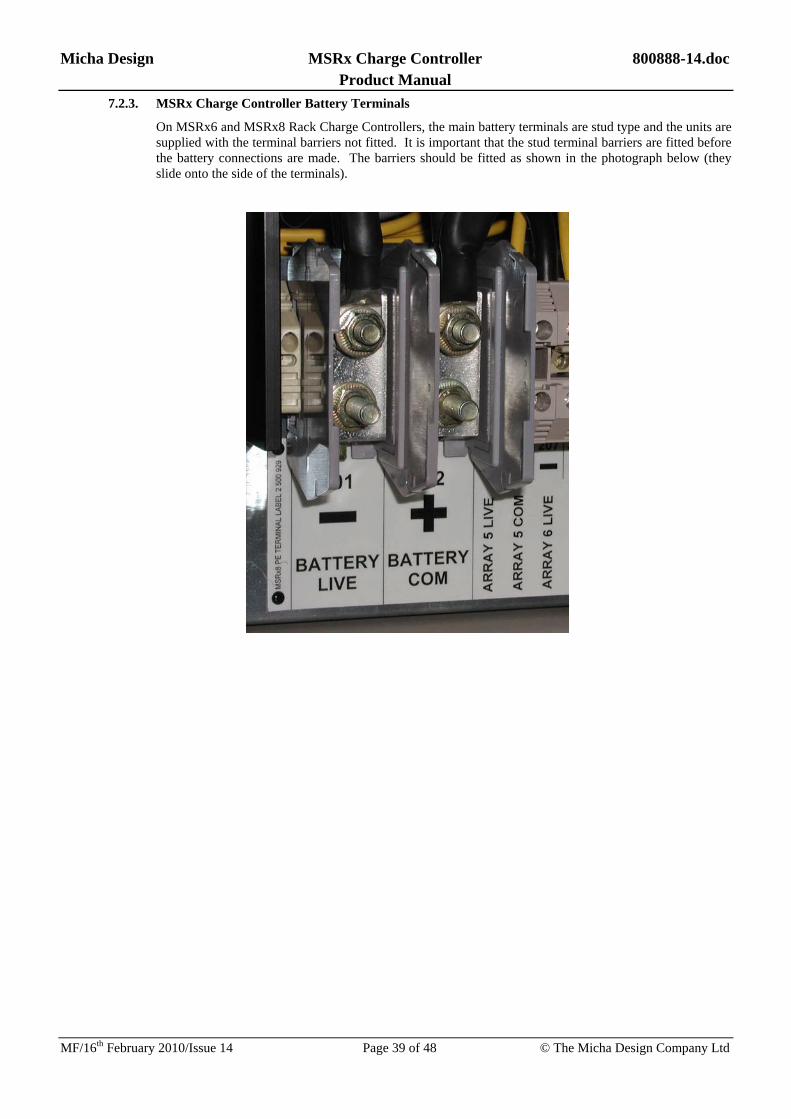
Micha Design MSRx Charge Controller 800888-14.doc Product Manual
MF/16th February 2010/Issue 14 Page 39 of 48 © The Micha Design Company Ltd
7.2.3. MSRx Charge Controller Battery Terminals
On MSRx6 and MSRx8 Rack Charge Controllers, the main battery terminals are stud type and the units are supplied with the terminal barriers not fitted. It is important that the stud terminal barriers are fitted before the battery connections are made. The barriers should be fitted as shown in the photograph below (they slide onto the side of the terminals).

Micha Design MSRx Charge Controller 800888-14.doc Product Manual
MF/16th February 2010/Issue 14 Page 40 of 48 © The Micha Design Company Ltd
7.3. MSRx 19” Rack Controller Unit Electrical Connections
COMMON POSITIVE SYSTEM ONLY
CAUTION: SOLAR MODULES AND BATTERIES CAN HAVE POTENTIALLY LETHAL VOLTAGES PRESENT AT THEIR TERMINALS AND PRESENT AN ENERGY HAZARD.
WARNING - RISK OF EXPLOSION:
The battery cable MUST be connected to the MSRx Control Unit BEFORE connecting to the battery
Make the electrical connections in the order shown in the following table:
COMMON POSITIVE SYSTEM ONLY
Connection 1st Location To Connection 2nd Location
BATT COM (+VE) MSRx Control Unit Battery Positive Terminal Battery
BATT LIVE (–VE) MSRx Control Unit Battery Negative Terminal Battery
Battery Sense BS+ MSRx Control Unit Battery Positive Terminal Battery
Battery Sense BS- MSRx Control Unit Battery Negative Terminal Battery
ARRAY 1-8 COM MSRx Control Unit Array Positive Terminal Array 1-8 Module
ARRAY 1-8 LIVE MSRx Control Unit Array Negative Terminal Array 1-8 Module
Load Positive Terminal Load 1 LOAD 1 COM MSRx Control Unit
Load Negative Terminal Load 1 LOAD 1 LIVE MSRx Control Unit
Load Positive Terminal Load 2 LOAD 2 COM MSRx Control Unit
Load Negative Terminal Load 2 LOAD 2 LIVE MSRx Control Unit
Red or White wire MSRx Temperature Sensor TEMP SENSE TS+ MSRx Control Unit
Black or Blue wire MSRx Temperature Sensor TEMP SENSE TS- MSRx Control Unit
7.3.1. MSRx Charge Controller MCBs
Ensure the Array MCBs are set to their ON positions to allow the arrays to charge the battery.
Ensure the Load MCBs are set to their ON positions to allow the battery to supply current to the load.
7.3.2. Battery Temperature
To ensure the Battery Temperature Compensation is as accurate as possible, proceed with the following instructions after the temperature of the batteries has stabilised:
Using the user switches (Menu, Up, Down and Select), navigate to the Battery Temperature screen (Menu 1, Screen 1). Use a small flat screwdriver to adjust the potentiometer VR1 on the MSRx 19” Rack Control PCB Assembly (inside the rack unit) so that the temperature shown on display is the same as the actual temperature as measured at the battery with a calibrated temperature meter.
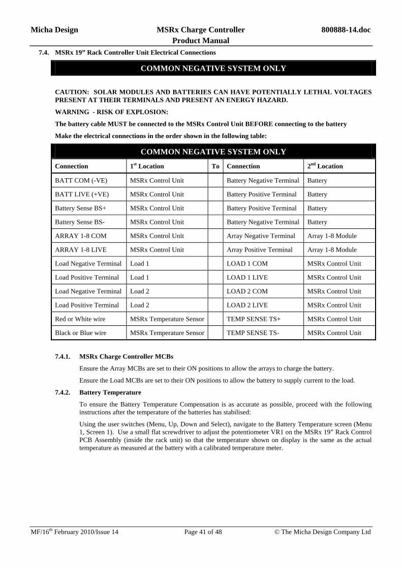
Micha Design MSRx Charge Controller 800888-14.doc Product Manual
MF/16th February 2010/Issue 14 Page 41 of 48 © The Micha Design Company Ltd
7.4. MSRx 19” Rack Controller Unit Electrical Connections
COMMON NEGATIVE SYSTEM ONLY
CAUTION: SOLAR MODULES AND BATTERIES CAN HAVE POTENTIALLY LETHAL VOLTAGES PRESENT AT THEIR TERMINALS AND PRESENT AN ENERGY HAZARD.
WARNING - RISK OF EXPLOSION:
The battery cable MUST be connected to the MSRx Control Unit BEFORE connecting to the battery
Make the electrical connections in the order shown in the following table:
COMMON NEGATIVE SYSTEM ONLY
Connection 1st Location To Connection 2nd Location
BATT COM (-VE) MSRx Control Unit Battery Negative Terminal Battery
BATT LIVE (+VE) MSRx Control Unit Battery Positive Terminal Battery
Battery Sense BS+ MSRx Control Unit Battery Positive Terminal Battery
Battery Sense BS- MSRx Control Unit Battery Negative Terminal Battery
ARRAY 1-8 COM MSRx Control Unit Array Negative Terminal Array 1-8 Module
ARRAY 1-8 LIVE MSRx Control Unit Array Positive Terminal Array 1-8 Module
Load Negative Terminal Load 1 LOAD 1 COM MSRx Control Unit
Load Positive Terminal Load 1 LOAD 1 LIVE MSRx Control Unit
Load Negative Terminal Load 2 LOAD 2 COM MSRx Control Unit
Load Positive Terminal Load 2 LOAD 2 LIVE MSRx Control Unit
Red or White wire MSRx Temperature Sensor TEMP SENSE TS+ MSRx Control Unit
Black or Blue wire MSRx Temperature Sensor TEMP SENSE TS- MSRx Control Unit
7.4.1. MSRx Charge Controller MCBs
Ensure the Array MCBs are set to their ON positions to allow the arrays to charge the battery.
Ensure the Load MCBs are set to their ON positions to allow the battery to supply current to the load.
7.4.2. Battery Temperature
To ensure the Battery Temperature Compensation is as accurate as possible, proceed with the following instructions after the temperature of the batteries has stabilised:
Using the user switches (Menu, Up, Down and Select), navigate to the Battery Temperature screen (Menu 1, Screen 1). Use a small flat screwdriver to adjust the potentiometer VR1 on the MSRx 19” Rack Control PCB Assembly (inside the rack unit) so that the temperature shown on display is the same as the actual temperature as measured at the battery with a calibrated temperature meter.

Micha Design MSRx Charge Controller 800888-14.doc Product Manual
MF/16th February 2010/Issue 14 Page 42 of 48 © The Micha Design Company Ltd
8. Re-Configuring the MSRx Charge Controller
8.1. Microcontroller (EPROM) Replacement
The operation of the MSRx Charge Controller is controller by a Microcontroller (sometimes known as the EPROM) which contains a software program. From time to time the software is upgraded to add features to the MSRx Charge Controller and a list of changes is included in Section 10 of this manual. Occasionally the Microcontroller may need to be replaced in the field. The following instructions detail how this should be done.
8.1.1. Ensure the Charge Controller is powered down, that all MCB’s and MCCB’s are in the OFF position and that the regulator chassis and enclosure are earthed.
8.1.2. Remove the four thumbscrews holding the facia plate in place as shown:
8.1.3. Identify the microcontroller on the circuit board as shown:
8.1.4. Using an IC removal tool or small screwdriver, carefully remove the existing IC.
8.1.5. Remove the replacement IC from its protective tube and carefully insert into the IC socket, ensuring all pins are straight. Note the orientation of the IC - the black dot on the label must be in the bottom left position. Avoid touching any pins or other components. The label on the IC identifies the Software (e.g. 801 197 in the example above), the version (Ver.2.0), a date code (27-10-05) and the black dot indicating orientation.
8.1.6. Replace the facia cover. Power up the controller and check the display shows the normal start-up screen.
8.1.7. Place the original IC into protective packaging and return for reprogramming.
8.1.8. For the MSRx 19” Rack Control PCB Assembly the Microcontroller reference is IC13 (the only 40-pin device on the PCB).
Microcontroller

Micha Design MSRx Charge Controller 800888-14.doc Product Manual
MF/16th February 2010/Issue 14 Page 43 of 48 © The Micha Design Company Ltd
8.2. System Voltage
8.2.1. The MSRx Charge Controller requires a power supply module suitable for the system voltage. The following table lists the appropriate MSRx PSU Module PCB Assemblies for the different system voltages.
System Voltage Description Micha Part Number 12V MSRx 12V PSU Module PCB Assembly 400 501
24V MSRx 24V PSU Module PCB Assembly 400 502
36V MSRx 36V PSU Module PCB Assembly 400 791
48V MSRx 48V PSU Module PCB Assembly 400 503
8.3. Changing the System Voltage
8.3.1. Disconnect Battery Sense connections from the battery
8.3.2. Disconnect Battery Power connections from the battery
8.3.3. Locate the MSRx PSU Module:
On the MSRx Steel Enclosure Units, the MSRx PSU Module is located on the MSRx PSU/Load PCB Assembly.
On the MSRx 19” Rack Units, the MSRx PSU Module is located on the MSRx 19” Rack Control PCB Assembly.
8.3.4. Remove the existing MSRx PSU Module PCB Assembly by removing the two nylon nuts securing the Module in place.
8.3.5. Install the replacement MSRx PSU Module PCB Assembly making sure that the connector mates properly with the header and secure the Module with the two nylon nuts.
8.3.6. The MSRx Charge Controller automatically senses the change of system voltage.

Micha Design MSRx Charge Controller 800888-14.doc Product Manual
MF/16th February 2010/Issue 14 Page 44 of 48 © The Micha Design Company Ltd
8.4. System Polarity
Note: Changing the PE/NE switch on the MSRx PSU PCB Assembly does not reconfigure the external system in any way. The switch is used to provide power to the MSRx Charge Controller and to indicate to the controller which system polarity has been chosen by the customer (or factory set). If the switch is set in the opposite polarity to the system, then the MSRx Charge Controller will not power up (the array inputs will remain disconnected from the battery and the load outputs will remain disconnected from the battery).
8.4.1. The MSRx Charge Controller requires minimal changes to configure the system for Common Positive or Common Negative use. Controllers are supplied with the polarity specified at the time or ordering.
8.4.2. If it becomes necessary to re-configure the unit, proceed with the following instructions:
8.5. Changing System Polarity from Common Positive to Common Negative – MSRx Steel Enclosure Units 8.5.1. The unit MUST be completely disconnected from any external electrical connections. Swap the
connections to J1 and J2, and then the connections to J3 and J4, as follows: 8.5.2. Identify the cable that is connected from LOAD 1 LIVE to the MSRx PSU/Load PCB Assembly – it is
connected via a ring crimp to J1 (also labelled “SHUNT NE”). Disconnect this cable from J1.
8.5.3. On the MSRx PSU/Load PCB Assembly, disconnect the cable from J2 (also labelled “SHUNT PE”) and connect it to J1.
8.5.4. Reconnect the cable from LOAD 1 LIVE to J2 on the MSRx PSU/Load PCB Assembly.
8.5.5. Identify the cable that is connected from LOAD 2 LIVE to the MSRx PSU/Load PCB Assembly – it is connected via a ring crimp to J3 (also labelled “SHUNT NE”). Disconnect this cable from J3.
8.5.6. On the MSRx PSU/Load PCB Assembly, disconnect the cable from J4 (also labelled “SHUNT PE”) and connect it to J3.
8.5.7. Reconnect the cable from LOAD 2 LIVE to J4 on the MSRx PSU/Load PCB Assembly. 8.5.8. Be sure to amend the terminal label to show the new polarity of the unit. 8.5.9. On the MSRx PSU/Load PCB Assembly, change the position of switch SW1 to the NE position. 8.5.10. The unit is now configured for Common Negative use (the MSRx Charge Controller automatically senses
the change of system polarity). 8.6. Changing System Polarity from Common Negative to Common Positive – MSRx Steel Enclosure Units
8.6.1. The unit MUST be completely disconnected from any external electrical connections. Swap the connections to J1 and J2, and then the connections to J3 and J4, as follows:
8.6.2. Identify the cable that is connected from LOAD 1 LIVE to the MSRx PSU/Load PCB Assembly – it is connected via a ring crimp to J2 (also labelled “SHUNT PE”). Disconnect this cable from J2.
8.6.3. On the MSRx PSU/Load PCB Assembly, disconnect the cable from J1 (also labelled “SHUNT NE”) and connect it to J2.
8.6.4. Reconnect the cable from LOAD 1 LIVE to J1 on the MSRx PSU/Load PCB Assembly. 8.6.5. Identify the cable that is connected from LOAD 2 LIVE to the MSRx PSU/Load PCB Assembly – it is
connected via a ring crimp to J4 (also labelled “SHUNT PE”). Disconnect this cable from J4. 8.6.6. On the MSRx PSU/Load PCB Assembly, disconnect the cable from J3 (also labelled “SHUNT NE”) and
connect it to J4. 8.6.7. Reconnect the cable from LOAD 2 LIVE to J3 on the MSRx PSU/Load PCB Assembly. 8.6.8. Be sure to amend the terminal label to show the new polarity of the unit. 8.6.9. On the MSRx PSU/Load PCB Assembly, change the position of switch SW1 to the PE position. 8.6.10. The unit is now configured for Common Positive use (the MSRx Charge Controller automatically senses
the change of system polarity).

Micha Design MSRx Charge Controller 800888-14.doc Product Manual
MF/16th February 2010/Issue 14 Page 45 of 48 © The Micha Design Company Ltd
8.7. Changing System Polarity from Common Positive to Common Negative – MSRx 19” Rack Units
8.7.1. The unit MUST be completely disconnected from any external electrical connections and access to the inside of the unit is required.
8.7.2. Identify the cable that is connected from LOAD 1 MCB to the MSRx 19” Rack Control PCB Assembly – it is connected via a ring crimp to J8 (also labelled “SHUNT NE”). Disconnect this cable from J8.
8.7.3. On the MSRx 19” Rack Control PCB Assembly, disconnect the cable from J9 (also labelled “SHUNT PE”) and connect it to J8.
8.7.4. Reconnect the cable from LOAD 1 MCB to J9 on the MSRx 19” Rack Control PCB Assembly.
8.7.5. Identify the cable that is connected from LOAD 2 MCB to the MSRx 19” Rack Control PCB Assembly – it is connected via a ring crimp to J6 (also labelled “SHUNT NE”). Disconnect this cable from J6.
8.7.6. On the MSRx 19” Rack Control PCB Assembly, disconnect the cable from J1 (also labelled “SHUNT PE”) and connect it to J6.
8.7.7. Reconnect the cable from LOAD 2 MCB to J1 on the MSRx 19” Rack Control PCB Assembly.
8.7.8. On the MSRx 19” Rack Charge Controller rear panel, remove the PE Terminal Label that is mounted below the main terminals (by removing the four 2-part black plastic rivets holding it in place) and replace it with a NE Terminal Label.
8.7.9. On the MSRx PSU Module, change the position of switch SW1 to the NE position.
8.7.10. The unit is now configured for Common Negative use (the MSRx Charge Controller automatically senses the change of system polarity).
8.8. Changing System Polarity from Common Positive to Common Negative – MSRx 19” Rack Units
8.8.1. The unit MUST be completely disconnected from any external electrical connections and access to the inside of the unit is required.
8.8.2. Identify the cable that is connected from LOAD 1 MCB to the MSRx 19” Rack Control PCB Assembly – it is connected via a ring crimp to J9 (also labelled “SHUNT PE”). Disconnect this cable from J9.
8.8.3. On the MSRx 19” Rack Control PCB Assembly, disconnect the cable from J8 (also labelled “SHUNT NE”) and connect it to J9.
8.8.4. Reconnect the cable from LOAD 1 MCB to J8 on the MSRx 19” Rack Control PCB Assembly.
8.8.5. Identify the cable that is connected from LOAD 2 MCB to the MSRx 19” Rack Control PCB Assembly – it is connected via a ring crimp to J1 (also labelled “SHUNT PE”). Disconnect this cable from J1.
8.8.6. On the MSRx 19” Rack Control PCB Assembly, disconnect the cable from J6 (also labelled “SHUNT NE”) and connect it to J1.
8.8.7. Reconnect the cable from LOAD 2 MCB to J6 on the MSRx 19” Rack Control PCB Assembly.
8.8.8. On the MSRx 19” Rack Charge Controller rear panel, remove the NE Terminal Label that is mounted below the main terminals (by removing the four 2-part black plastic rivets holding it in place) and replace it with a PE Terminal Label.
8.8.9. On the MSRx PSU Module, change the position of switch SW1 to the PE position.
8.8.10. The unit is now configured for Common Positive use (the MSRx Charge Controller automatically senses the change of system polarity).

Micha Design MSRx Charge Controller 800888-14.doc Product Manual
MF/16th February 2010/Issue 14 Page 46 of 48 © The Micha Design Company Ltd
9. Troubleshooting Guide
9.1. Common Problems
Situation Possible causes Action
The display is inactive The MSRx display powers down after 4 minutes from the last user switch press
Press any front panel switch to activate the display
The display is inactive The Polarity switch on the MSRx PSU Module may be incorrectly set
Set the Polarity switch correctly
The display is inactive The MSRx PSU Module may not be functioning correctly
Check the PSU Module output voltages (see section 9.2)
The display indicates:
“Fault - BY Sense”
The Battery Sense connections are not made correctly
Check the Battery Sense connections
The display indicates:
“Fault – Temp Sen”
The Temperature Sensor connections are not made correctly
Check the Temperature Sensor connections
Low Volts Alarm / Load Cut Alarm
or Load is Disconnected
Prolonged poor weather has resulted in the battery being discharged
Minimise load until light conditions improve
Low Volts Alarm / Load Cut Alarm
or Load is Disconnected
Extra loads have been added which exceeds the design
Remove the extra loads
Low Volts Alarm / Load Cut Alarm
or Load is Disconnected
The Battery Sense connections are not made correctly
Check the Battery Sense connections
Low Volts Alarm / Load Cut Alarm
or Load is Disconnected
The Load MCB is switched off Switch the Load MCB on
Low Volts Alarm / Load Cut Alarm
or Load is Disconnected
The Array MCBs are switched off Switch the Array MCBs on
Low Volts Alarm / Load Cut Alarm
or Load is Disconnected
The Load Switch is faulty Test the Load Switch using Menu 3
Low Volts Alarm / Load Cut Alarm
or Load is Disconnected
The battery is discharged because the array switches are faulty
Test the Array Switches using Menu 4
High Volts Alarm The arrays are not being disconnected from the battery
Test the Array Switches using Menu 4

Micha Design MSRx Charge Controller 800888-14.doc Product Manual
MF/16th February 2010/Issue 14 Page 47 of 48 © The Micha Design Company Ltd
9.2. Test Procedures
Tests Procedure
Test the load switch using Menu 3
Navigate to Menu 3 and use the Select switch to change the present state of the Load Switch.
Check that the solid-state switch works by using a DVM with a current clamp on the output cable to ensure that current flows when the switch should be closed and no current flows when the switch should be open.
Alternatively, use a DVM to measure the voltage across the Load Output terminals. When the load switch is closed, the voltage should equal the battery voltage (within 0.5V). When the load switch is open, the voltage should be zero.
Test the array switches using Menu 3
Navigate to Menu 3 and use the Select switch to change the present state of the Array Switch.
Check that the solid-state switch works by using a DVM with a current clamp on the output cable to ensure that current flows when the switch should be closed and no current flows when the switch should be open.
Alternatively, use a DVM to measure the voltage across the Array Input terminals. When the array switch is closed, the voltage should equal the battery voltage (within 0.5V). When the array switch is open, the voltage should be the open circuit array voltage (during the day) or close to zero (at night).
Check the PSU Module output voltages
Disconnect the ribbon cable from the MSRx Control PCB Assembly to J11 of the MSRx PSU/Load PCB Assembly. Using a DVM make the following measurements on connector J1 of the MSRx PSU Module (Pin 5 is nearest to SW1):
Connect the negative probe to pin 2 of J1 and the positive probe to pin 5 of J1 and ensure the DVM indicates +12.0 ± 0.5V.
Connect the negative probe to pin 2 of J1 and the positive probe to pin 4 of J1 and ensure the DVM indicates –12.0 ± 0.5V.
If these two measurements are correct then the MSRx PSU Module would appear to be OK.

Micha Design MSRx Charge Controller 800888-14.doc Product Manual
MF/16th February 2010/Issue 14 Page 48 of 48 © The Micha Design Company Ltd
10.Software History
Software Version
Date Released
Comments
801 313 Ver 1.0
6th July 2006 Change to PIC18F4620 Microcontroller – requires:
Standard Unit: Control PCB Assembly 400327 Issue 4 or higher
19” Rack Unit: Control PCB Assembly 400766 Issue 2 or higher
Added Programmable Standard Alarm Relays to Menu C
Removed obsolete Relay Menus from Menu B and C
Added Regulation Hysteresis to Menu D
Default Battery settings now in Menu F - identified by name of battery
Added Absolyte Battery Settings
Added DRM Control Menus to new Menu E and sub menus
801 313 Ver 1.1
31st July 2006 Added DRM RS232 Communications and Data Logging
Test Mode now disabled 30 mins after being enabled
801 313 Ver 1.2
26th Sept 2006 Added Gel/OPzV Battery Settings
Added Analogue Input Module Set up Screen to Menu E
Added Auxiliary Volts Screen to Menu 1 (Screen 2)
4-20mA Transducer Module – Battery Current Settings more flexible
801 313 Ver 1.3
7th Nov 2006 Fixed bug in Load Current sign display
If Aux Temp Enabled but result outside -30C to +60C then display ---.-C
801 313 Ver 1.4
28th Nov 2006 Added RS232 Upload of parameters from PC
Added Array Shunt 1 & 2 Value = 500A
801 313 Ver 1.5
24th July 2007 Fixed bug on 4-20mA setting screens:
Up to Version 1.4 all the transducers output 4mA when looking at Unit 1 4mA setting and
Up to Version 1.4 all the transducers output 20mA when looking at Unit 1 20mA setting
801 313 Ver 1.6
28th Nov 2008 Defaults now only written at first time power up
Added LC1Alm=Off to Relay Alarm Functions (i.e. active state = relay off)
801 313 Ver 1.7
5th May 2009 Added Low Volts 2 Function Run Time on Menu D Screen 9 (See Section 3.12)
801 313 Ver 1.8
29th May 2009 Added 200A Shunt to Array Shunt selections (Menu D) and calculation (Section 4.17)
Added Disable Link Function selection in Menu D Screen 10 (Section 4.17)
801 313 Ver 1.9
13th Aug 2009 Added 250A Shunt to Array Shunt selections (Menu D) and calculation (Section 4.17)
801 313 Ver 2.0
2nd Feb 2010 Added Modbus Communications Protocol to serial communications (Section 5.5, 5.6)
Added Modem Initialisation on power up (Section 5.7)
Related Documents